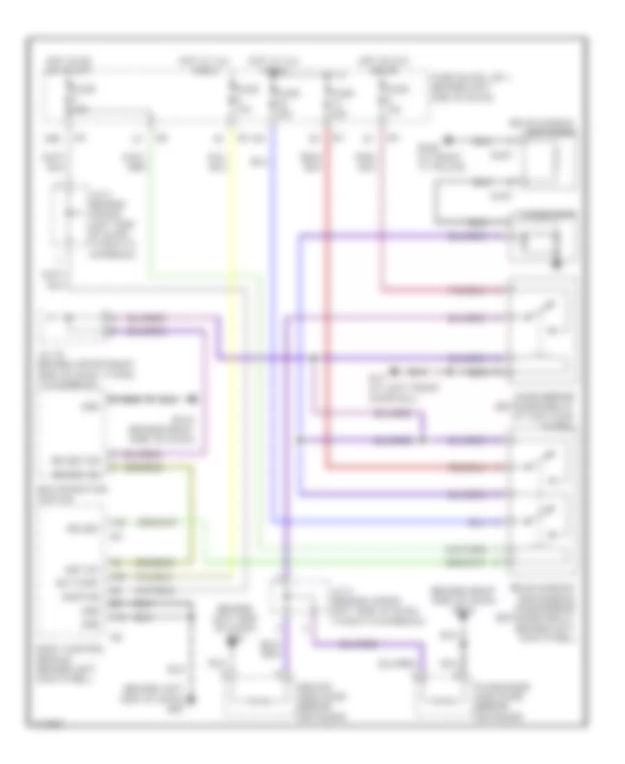
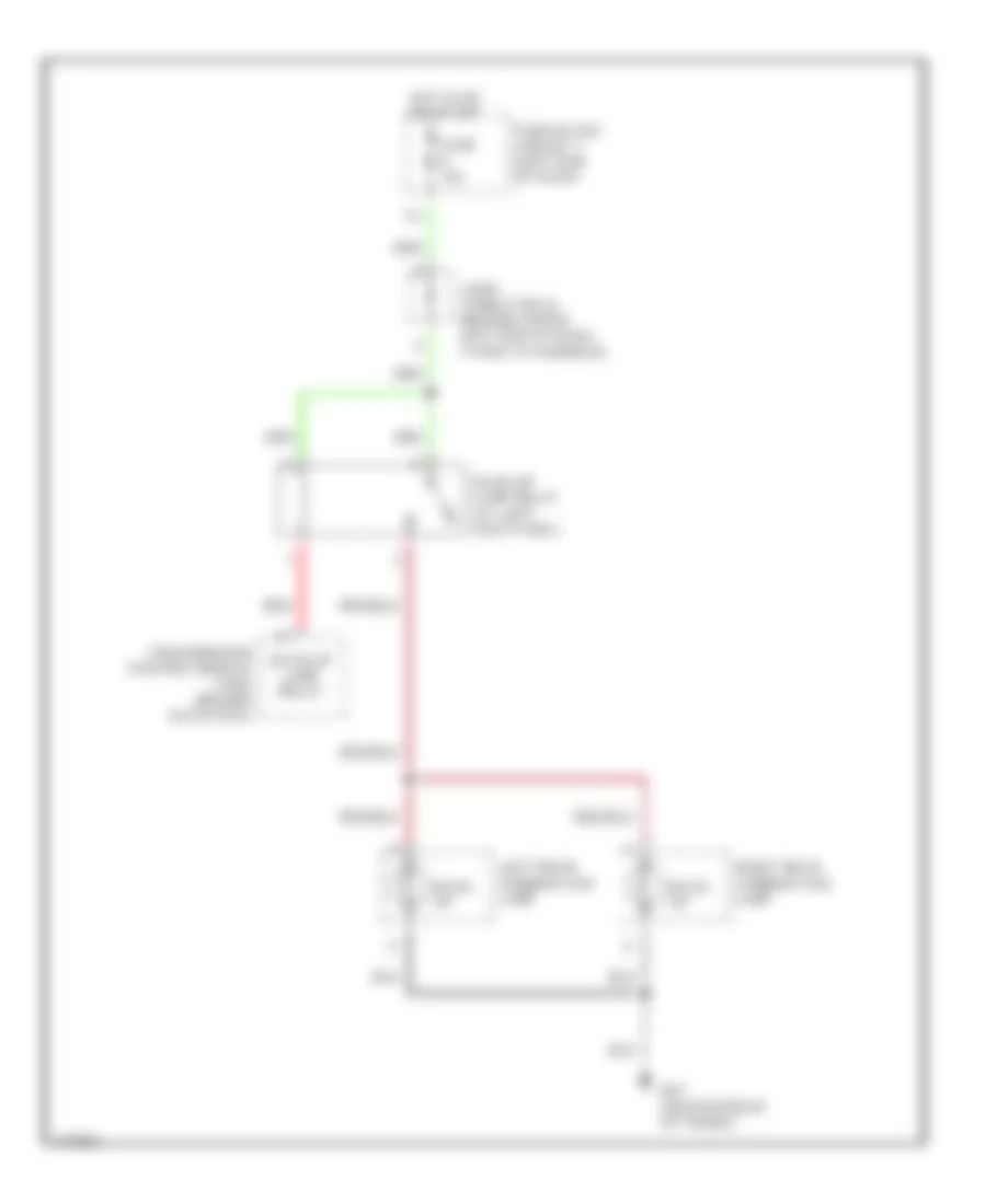
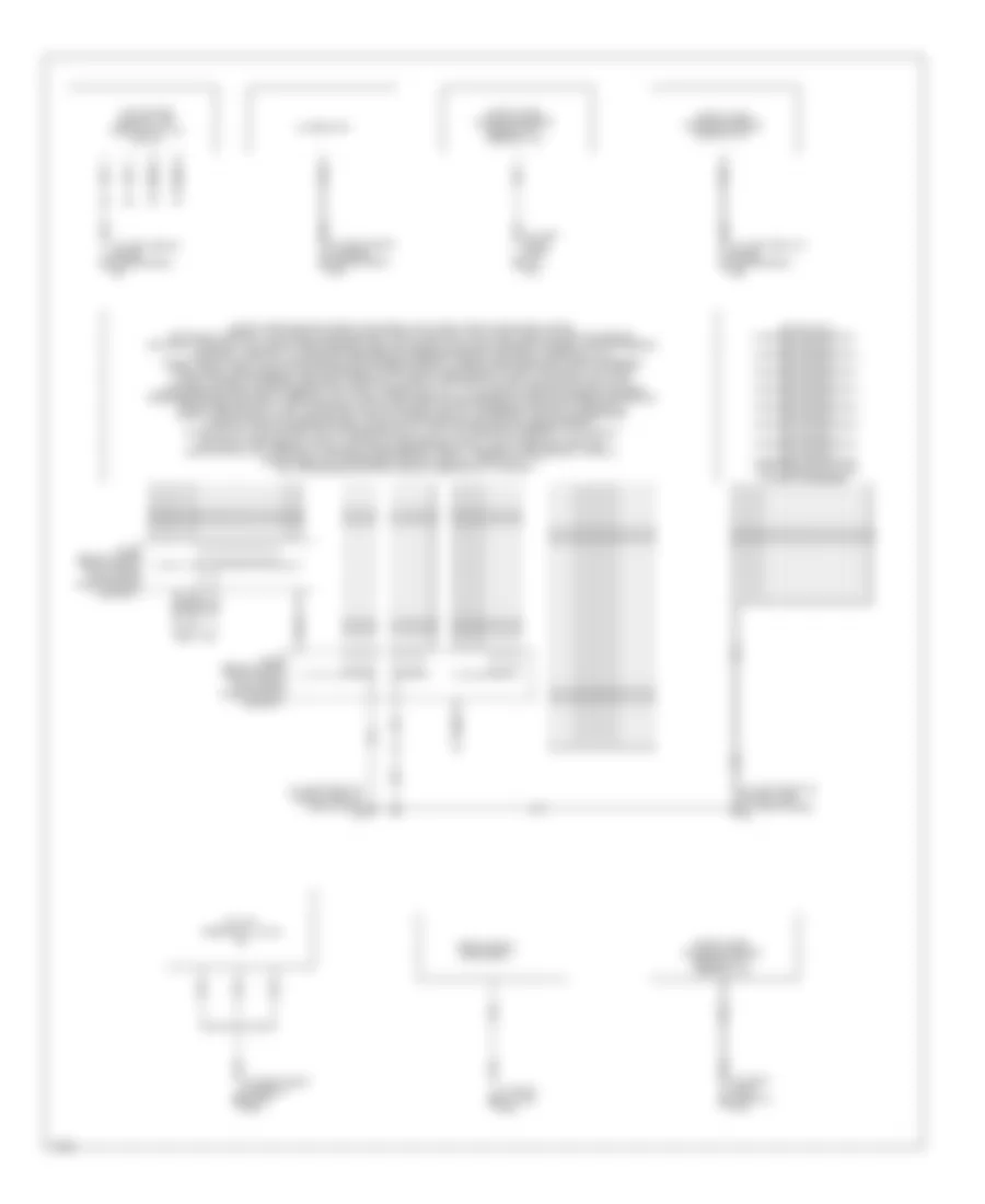
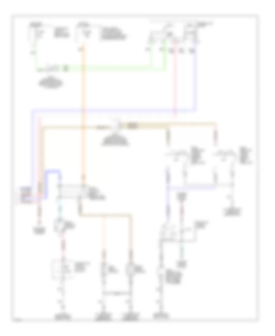
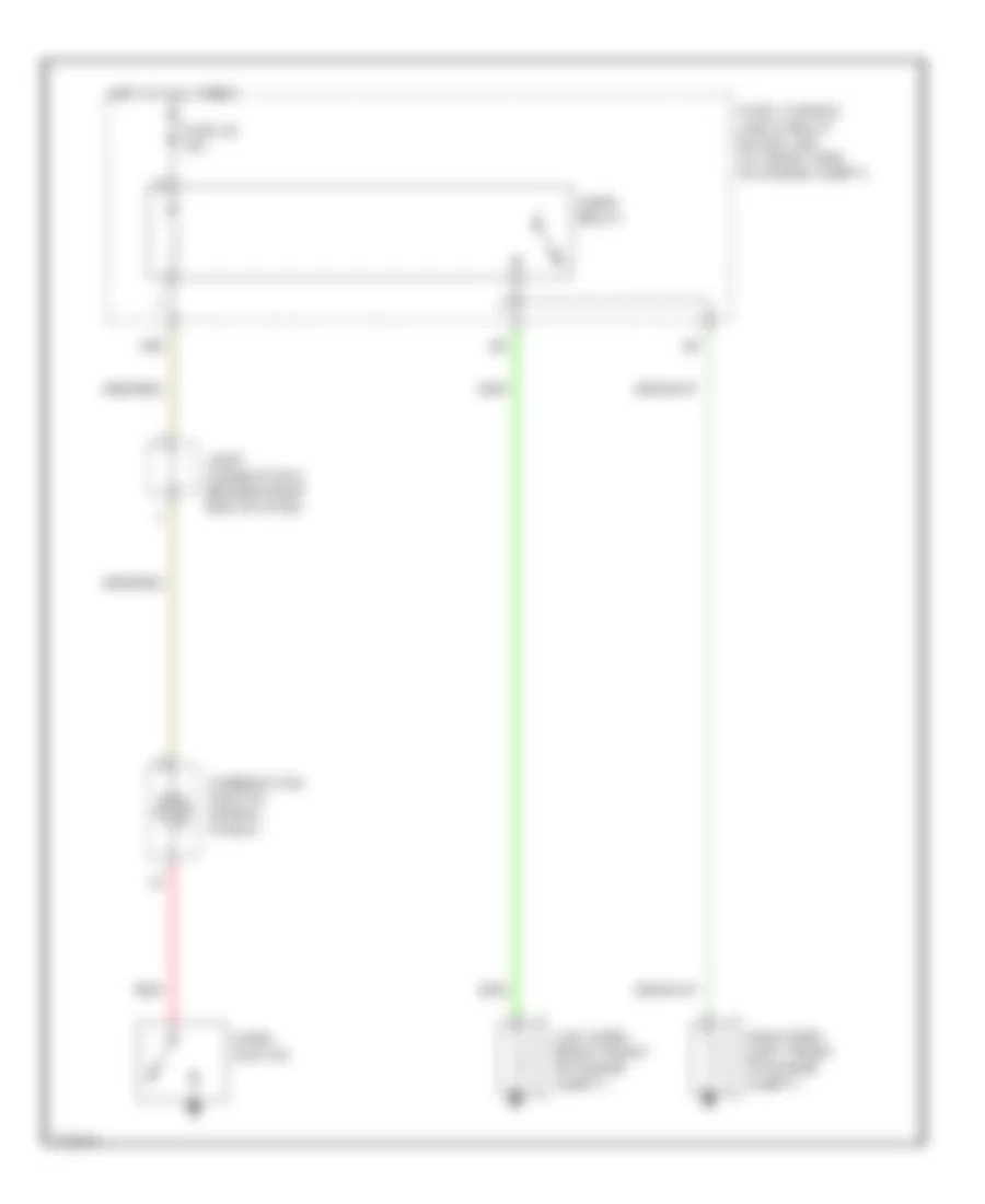
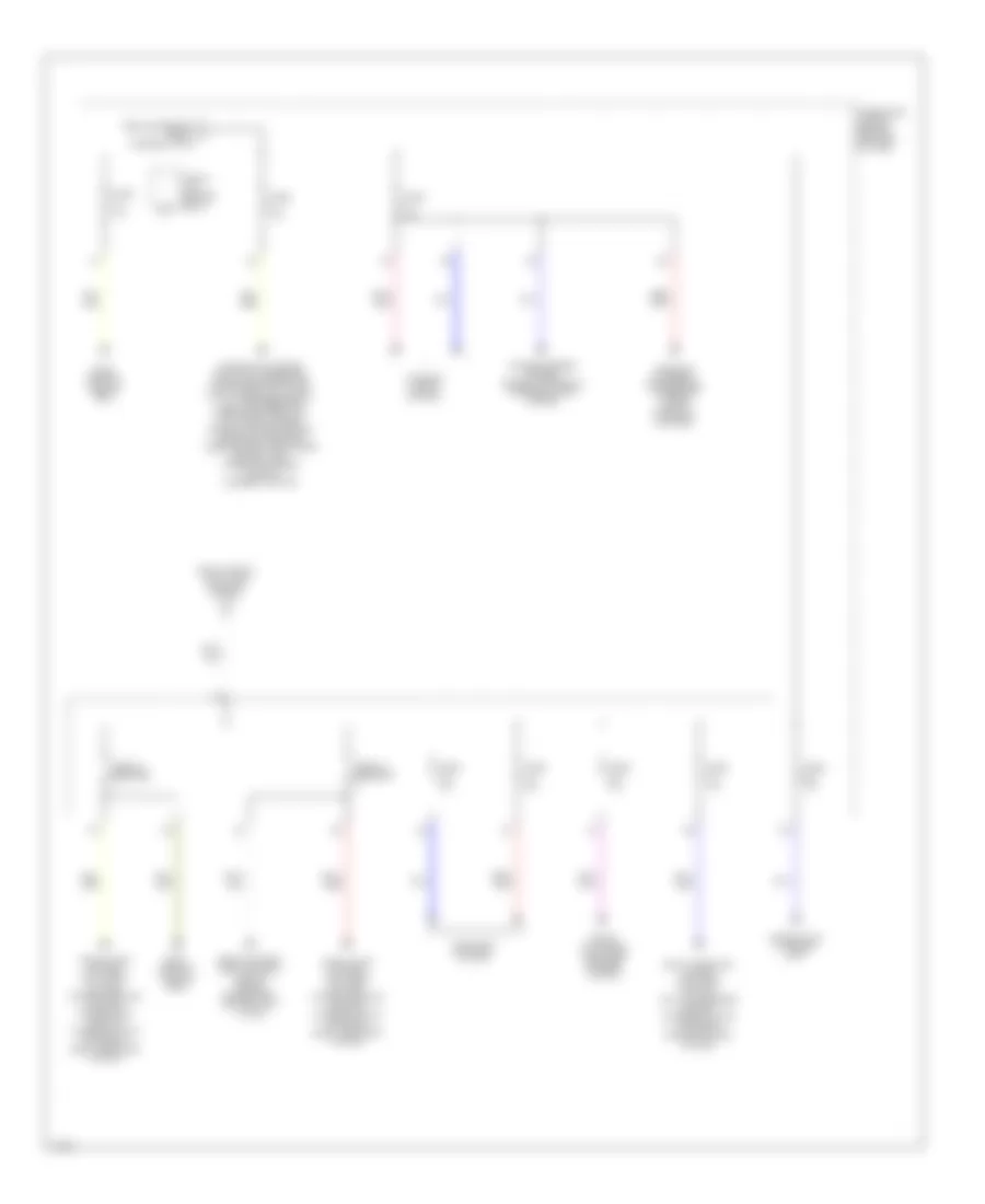
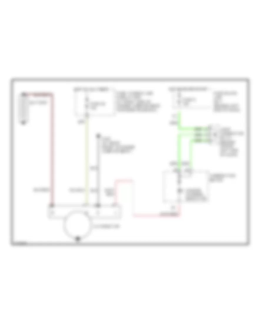
AIR CONDITIONING
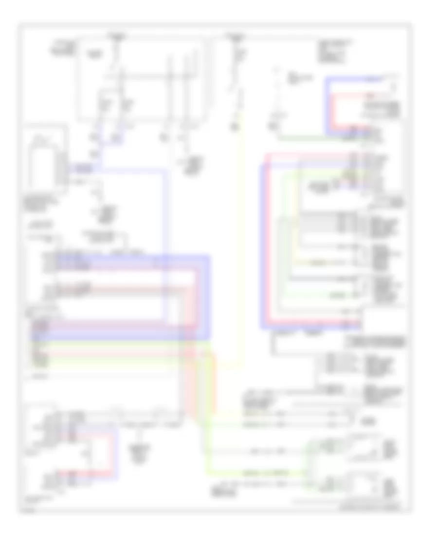
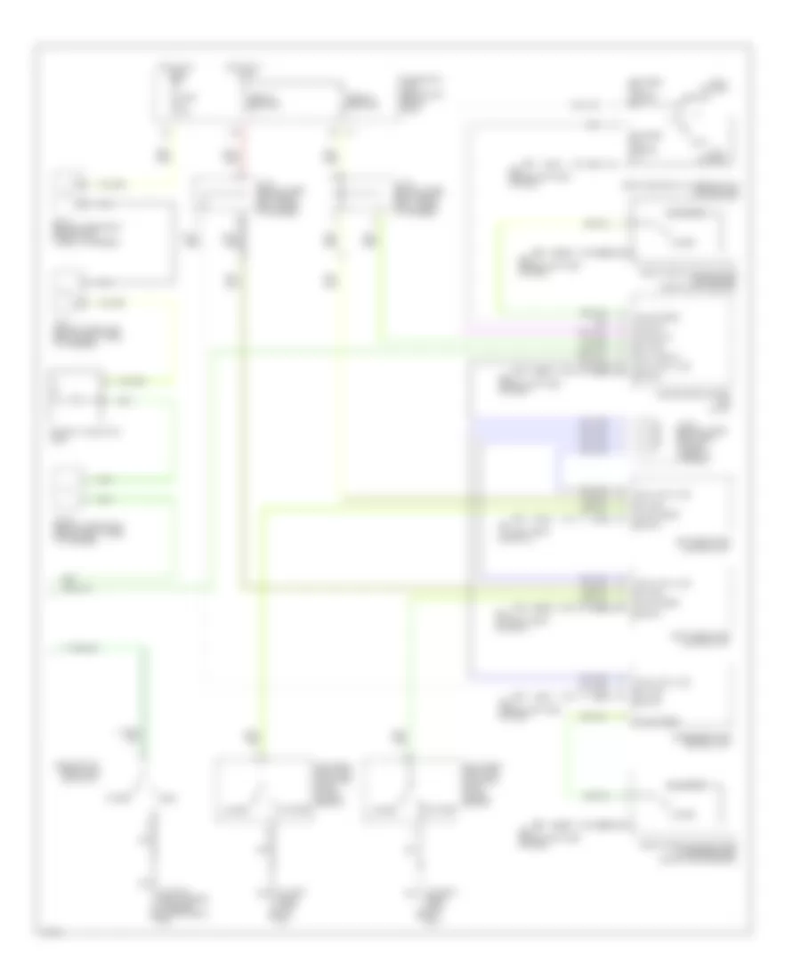
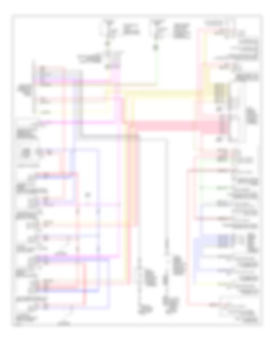
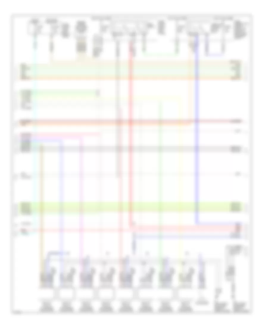
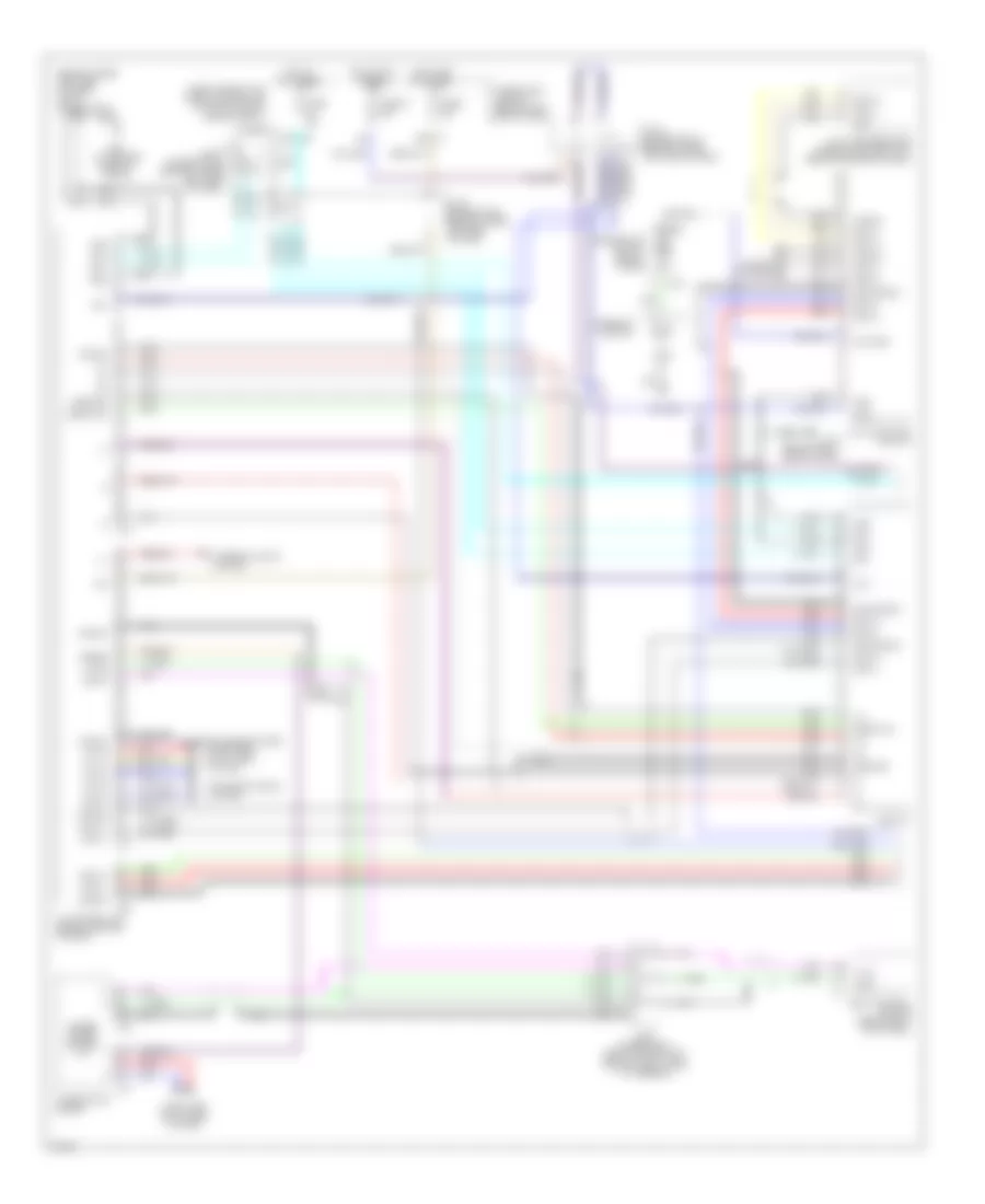
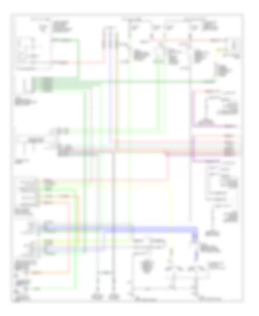
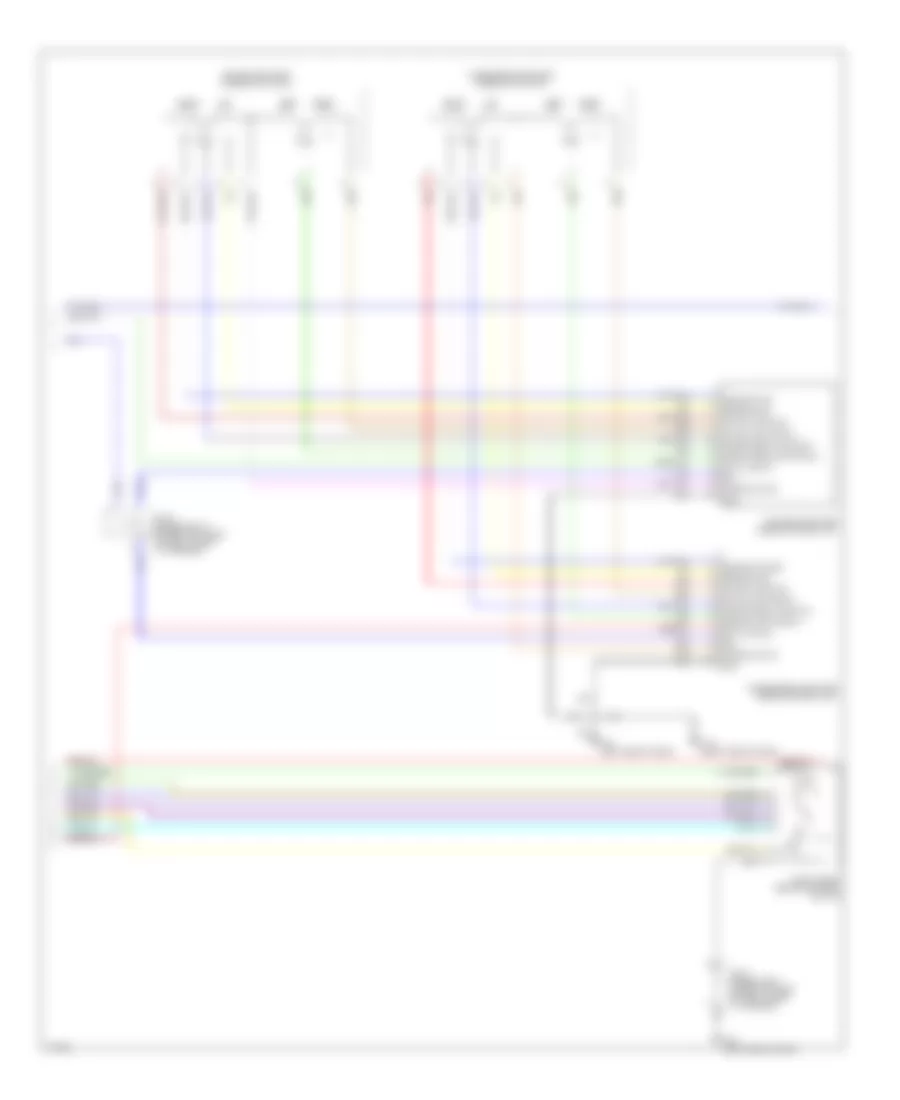
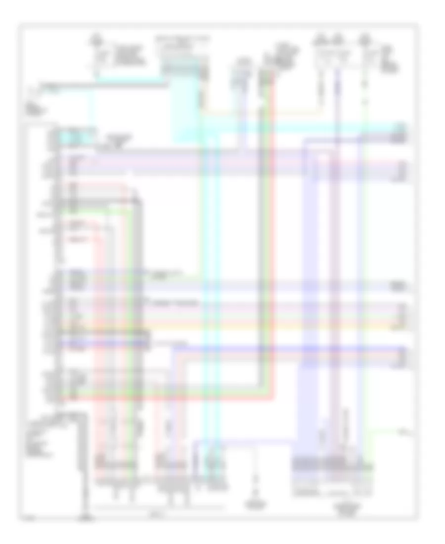
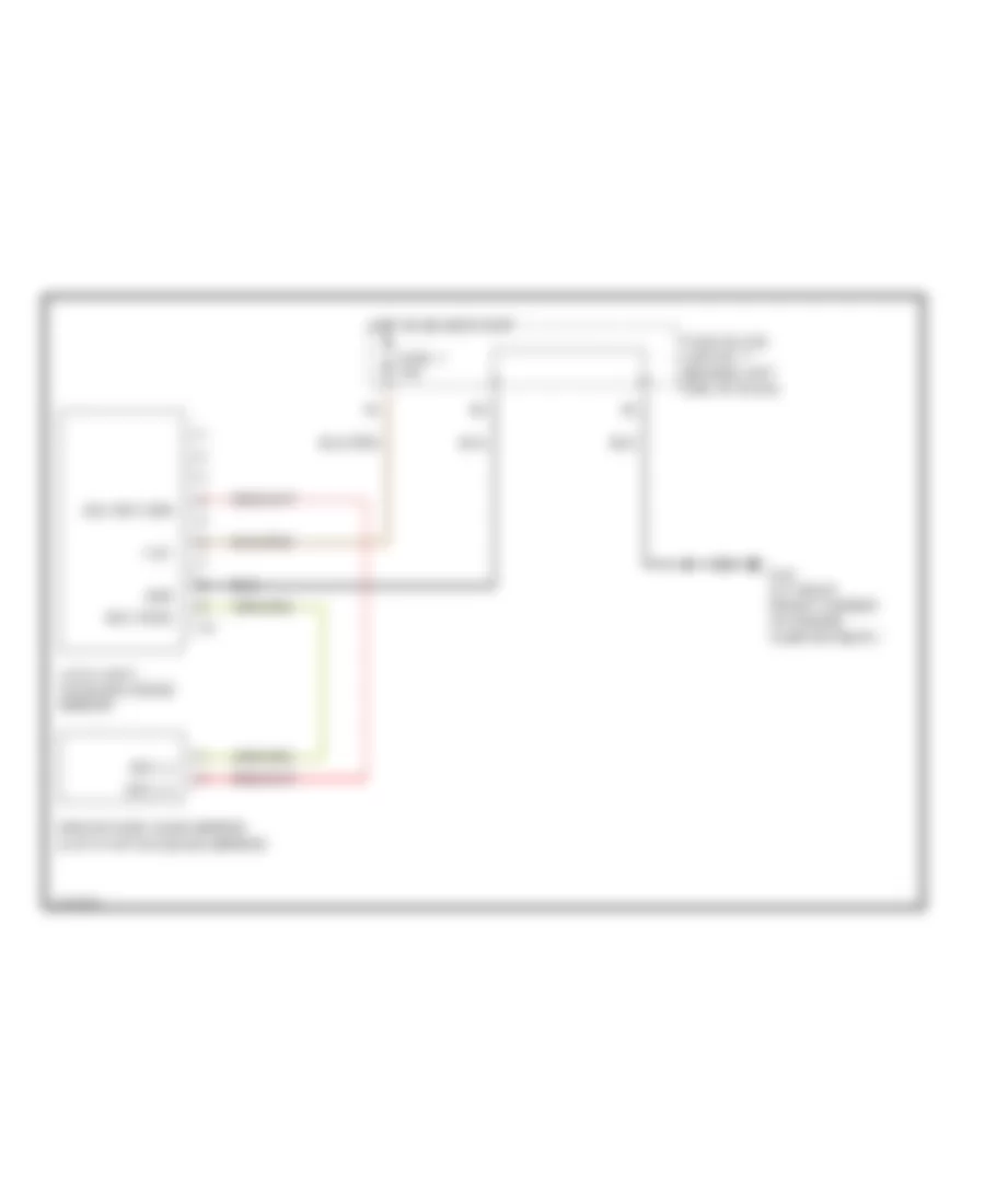
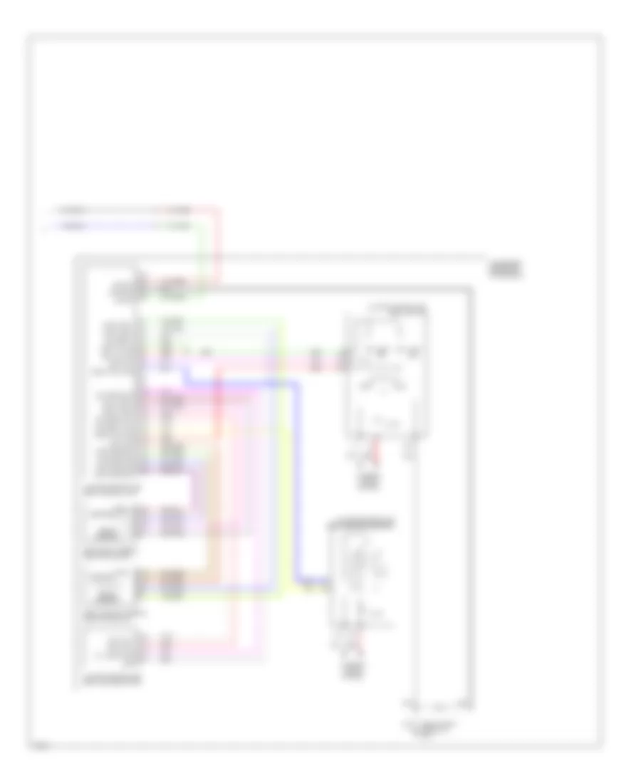
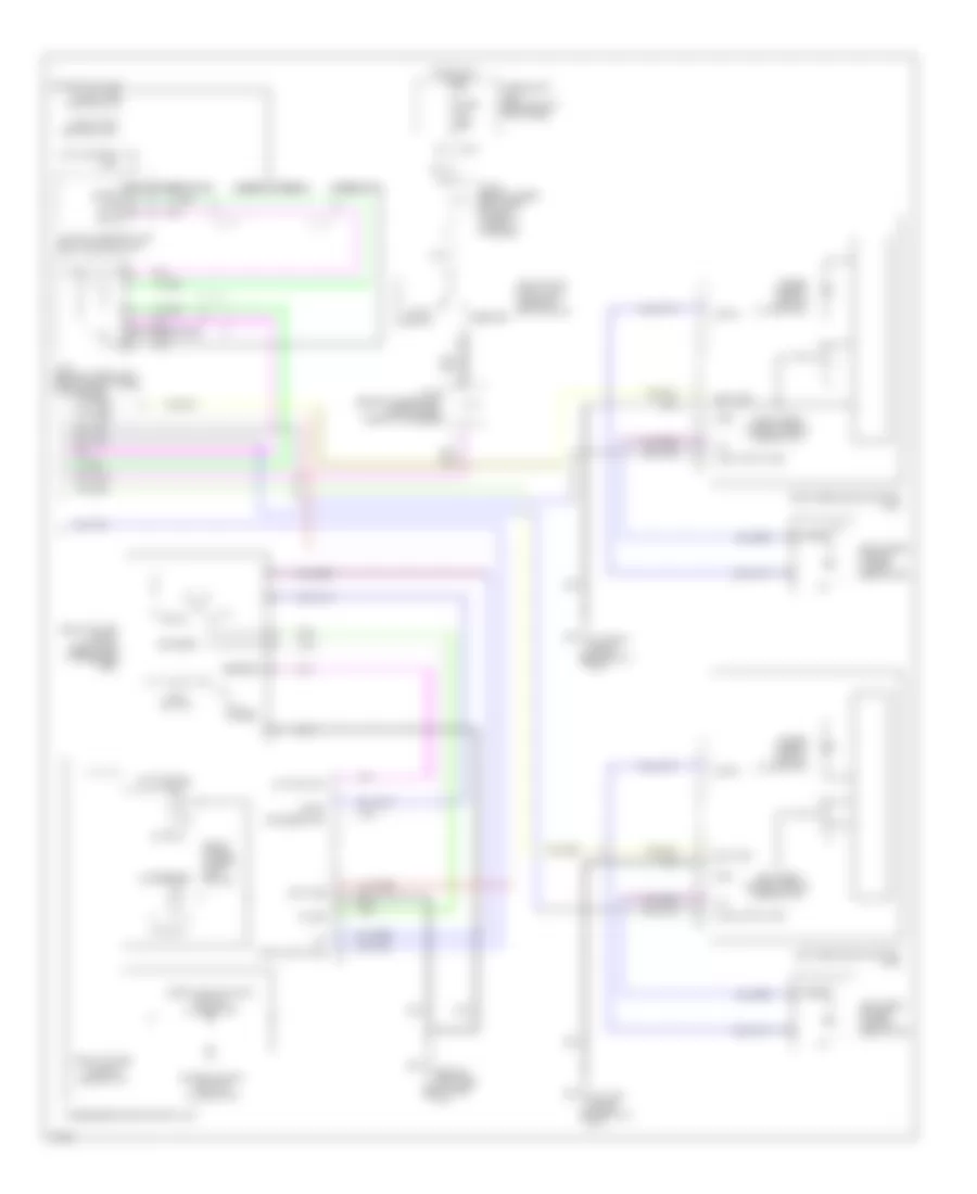
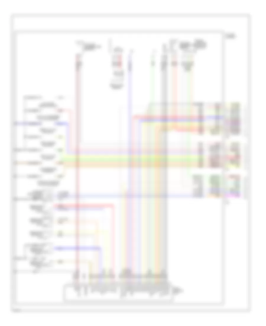
Automatic A/C Wiring Diagram (1 of 2) for Infiniti M45 2003

List of elements for Automatic A/C Wiring Diagram (1 of 2) for Infiniti M45 2003:
- (behind left side of dash) m25
- (behind right side of dash) m114
- (behind right side of dash) m115
- A/c auto amplifier (behind right side of dash, near blower motor)
- A/c-av (fr tx)
- Acc
- Air mix door motor (passenger side) (behind right side of dash, on heater unit)
- Amb sens
- Ambient sensor (behind center of front bumper)
- Av-a/c (fr rx)
- Bat
- Clk (fr)
- Combination meter
- Comp on comp on
- Compressor
- Computer data lines system
- Ecm comp
- Ecv
- Ecv solenoid valve
- F10
- Fan on
- Fan pwm
- Fuse 10a
- Fuse block (j/b) no.1 (behind left end of dash)
- Gnd
- Hot at all times
- Hot in acc or on
- Hot in on or start
- Ign
- In-vehicle sensor (behind lower center of dash)
- Incar sens
- Intake door motor (under right side of dash, on intake unit)
- Intake sens
- J/c 11 (behind upper right side of dash, taped to harness)
- J/c 14 (behind upper right side of dash, taped to harness)
- J/c 16 (behind upper right side of dash, taped to harness)
- J/c 19 (behind upper right side of dash, taped to harness)
- Lan sig
- M119
- M120
- M41
- M42
- Magnetic clutch
- Mode door motor (passenger side) (behind lower right side of dash, on heater unit)
- Pnk
- Red
- Sens gnd
- Speed sens
- Sun load sensor (under top left side of dash)
- Sun sens
- Unified meter control unit
- Vactr
- W/t sens
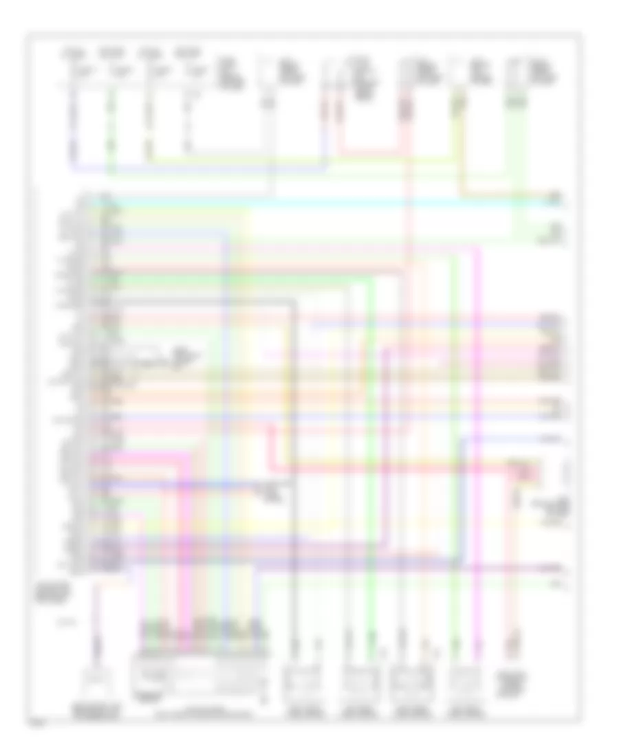
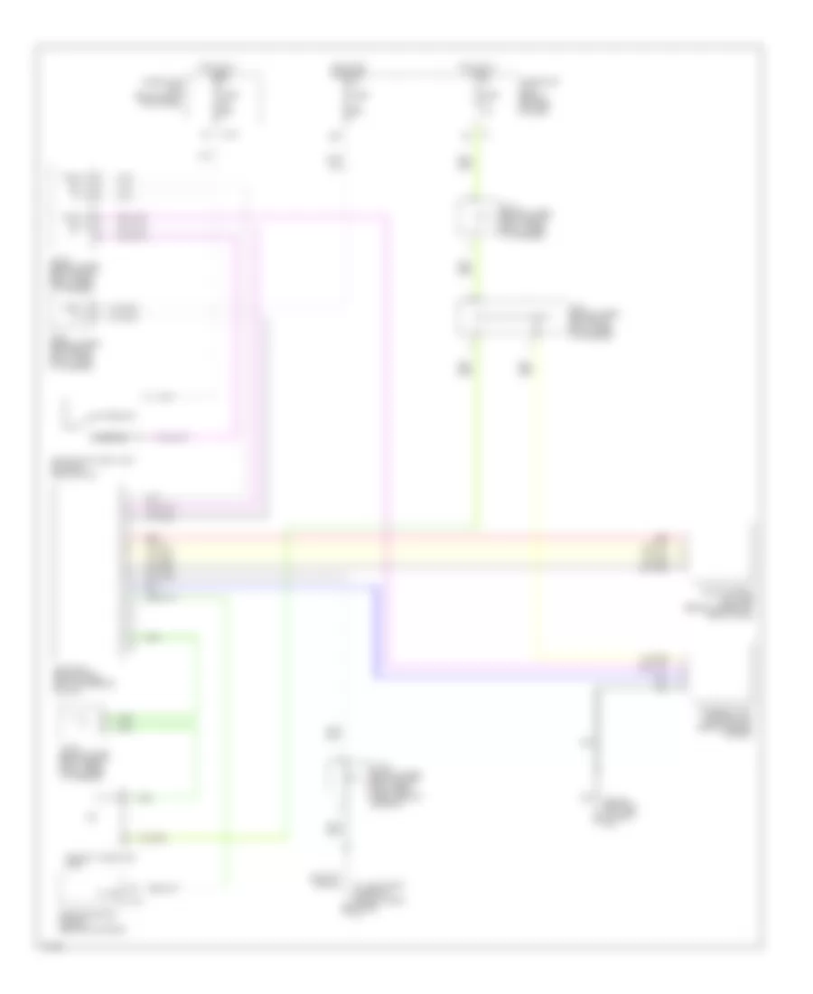
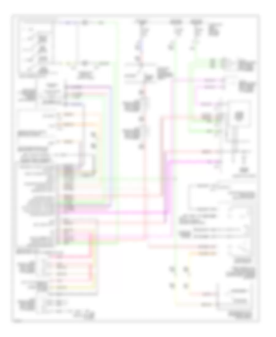
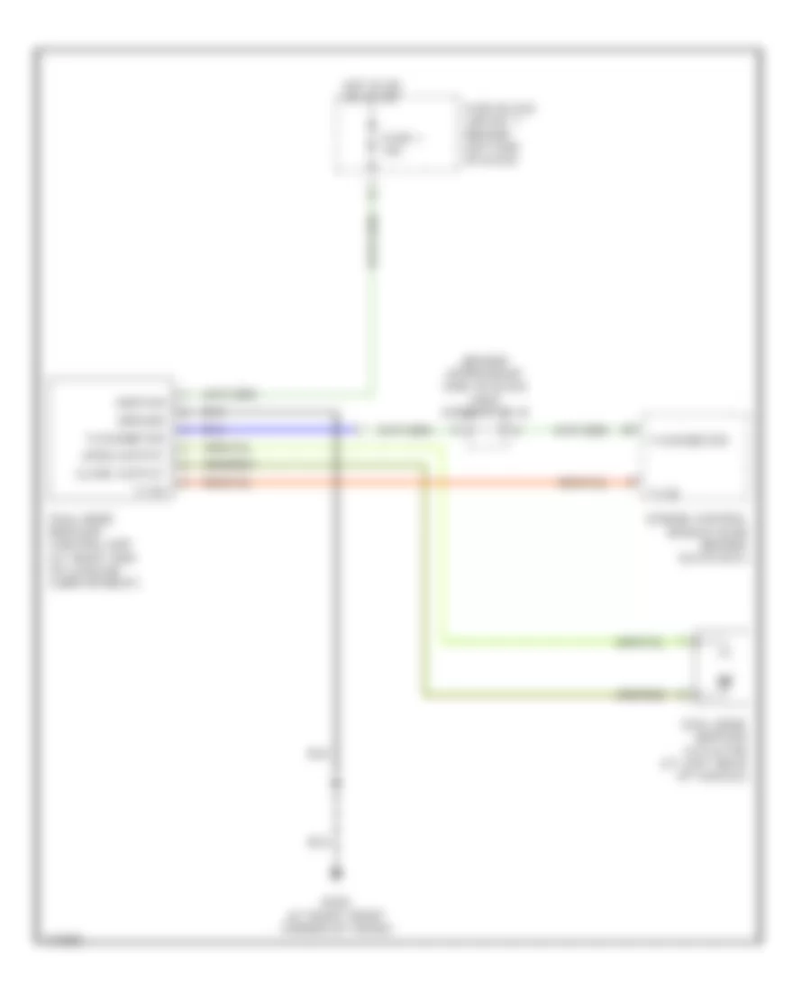
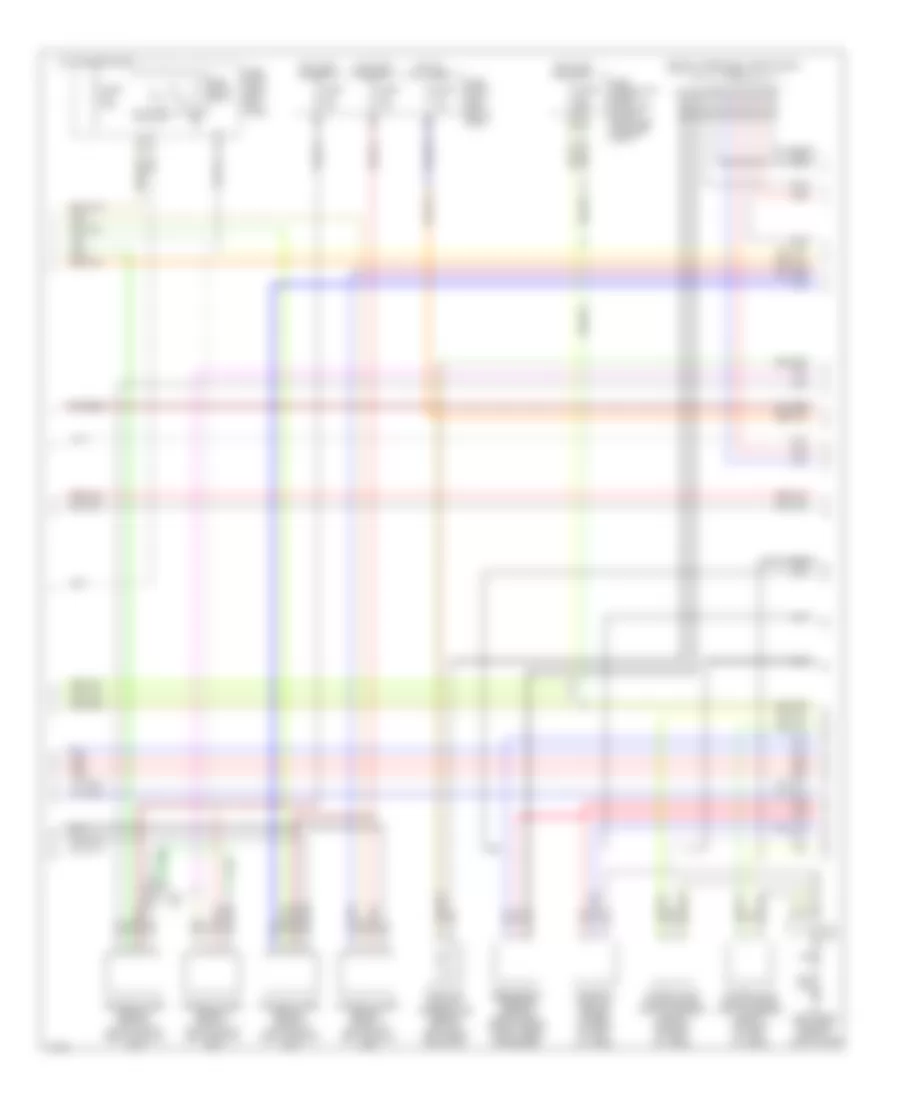
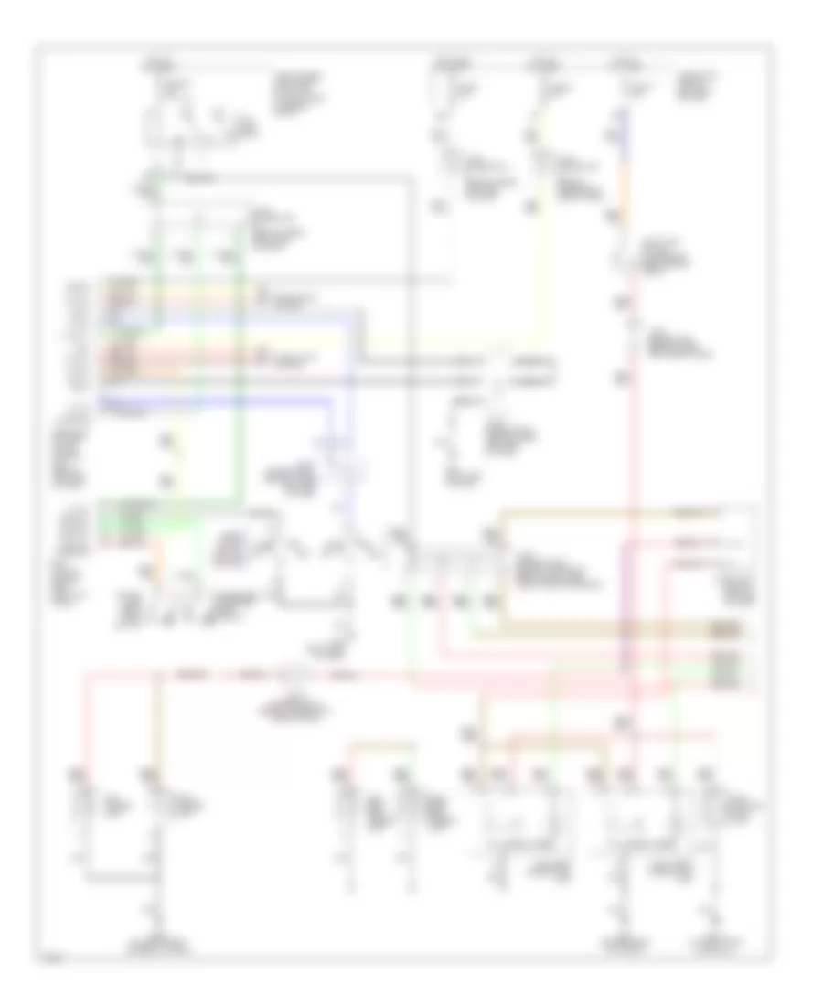
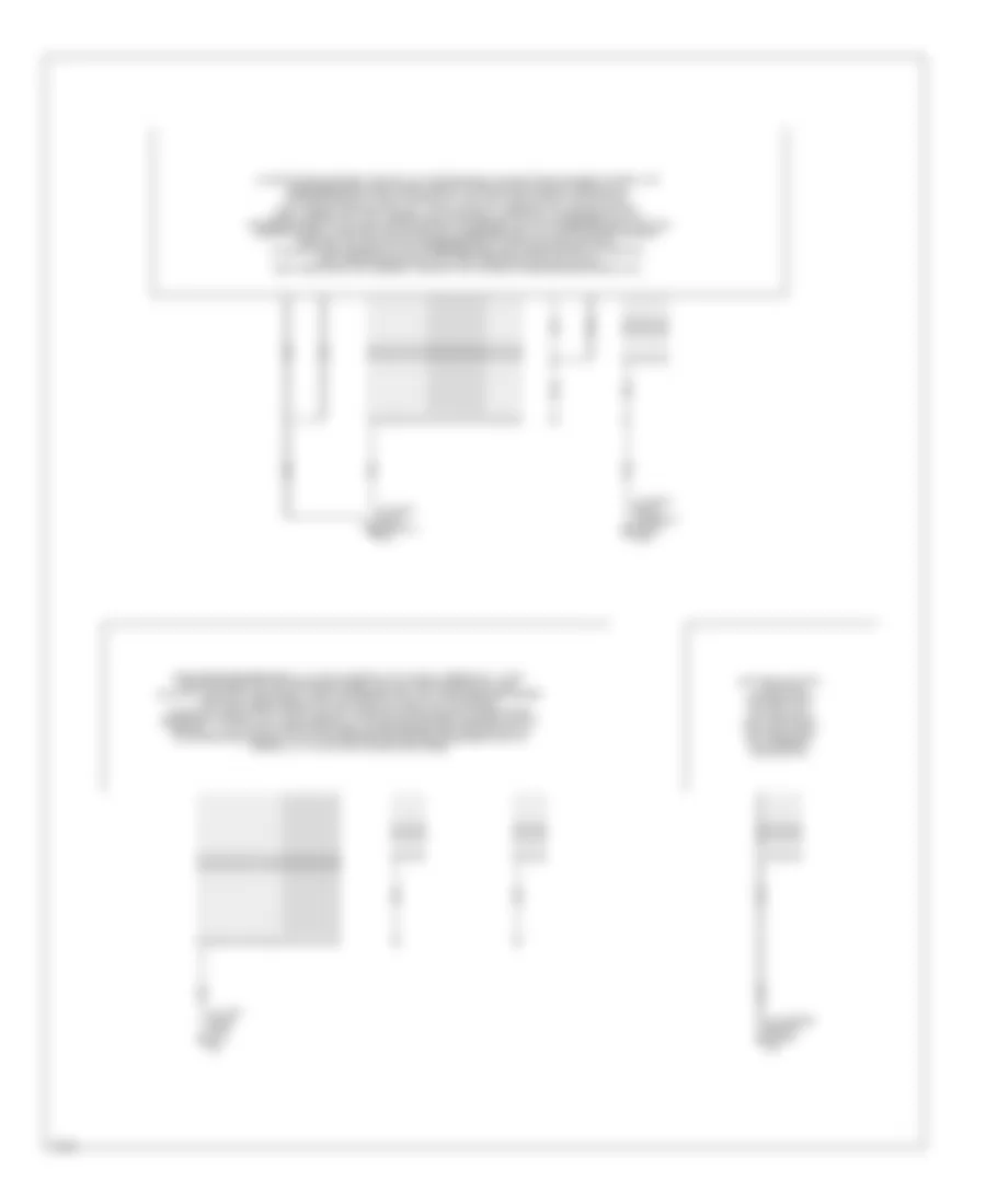
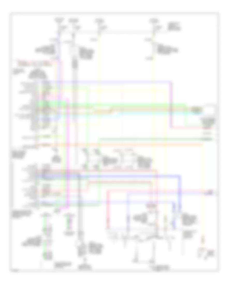
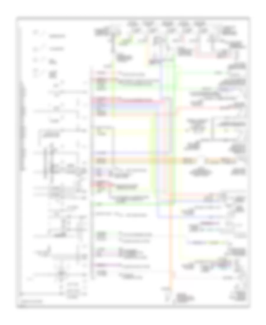
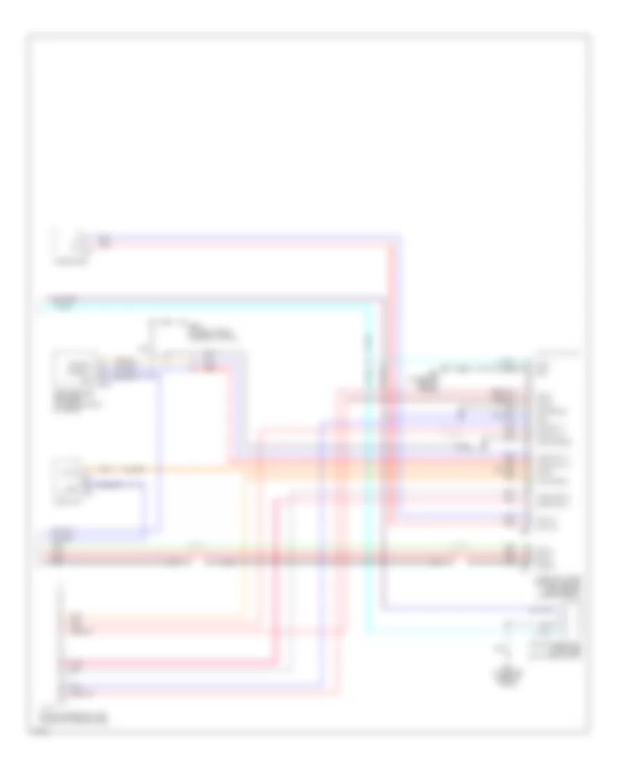
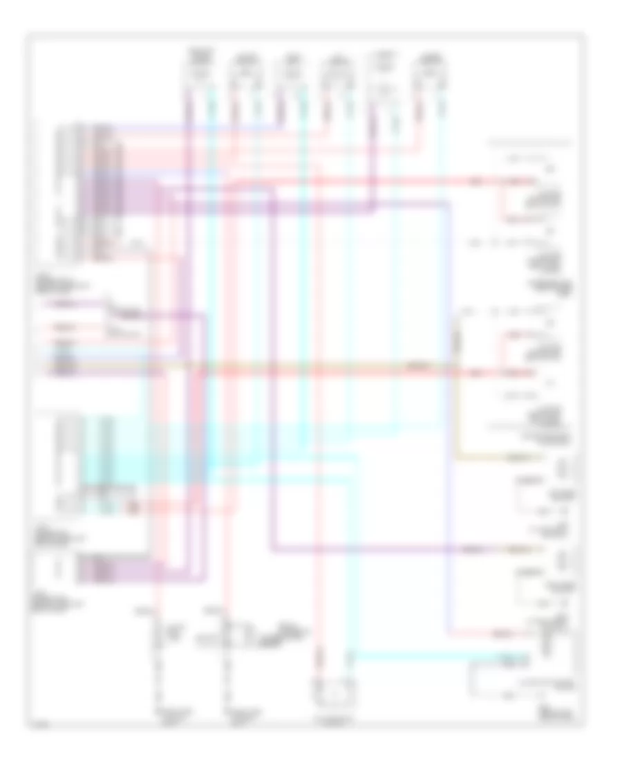
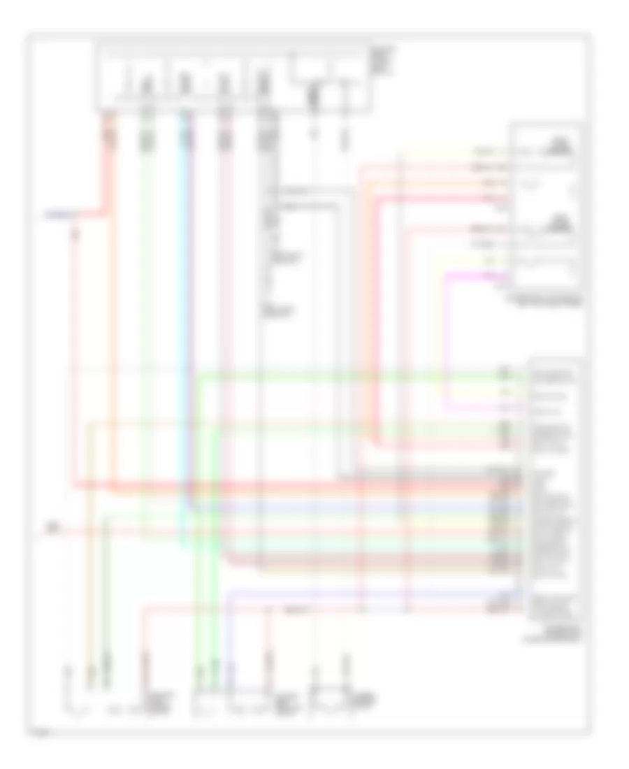
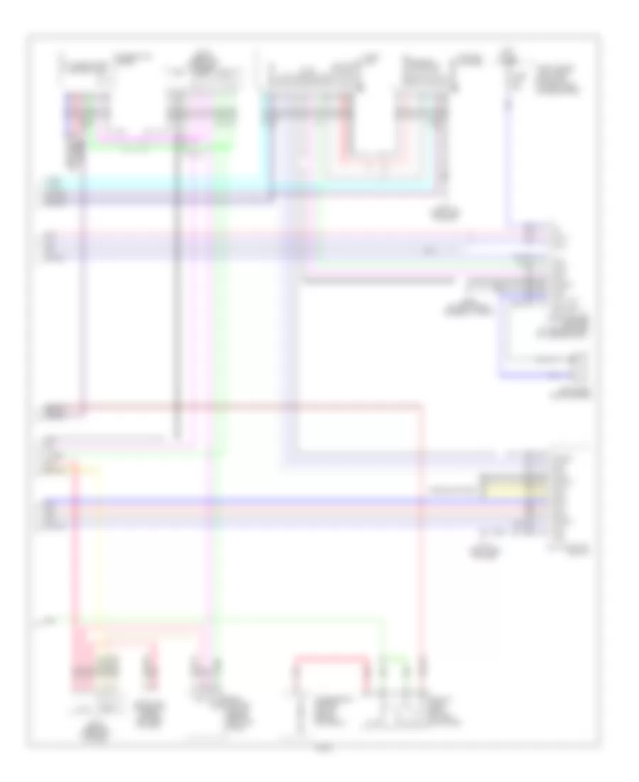
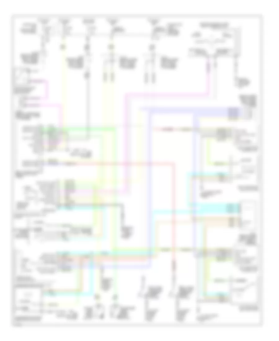
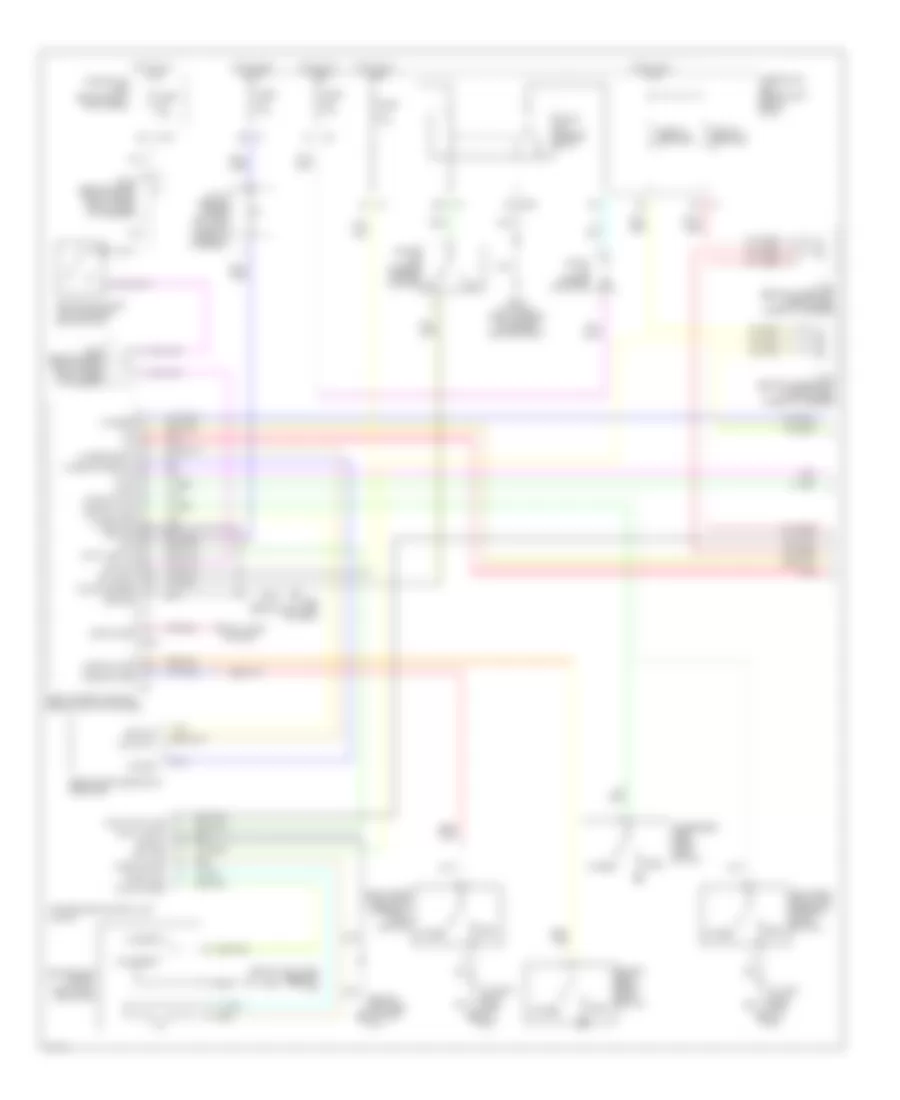
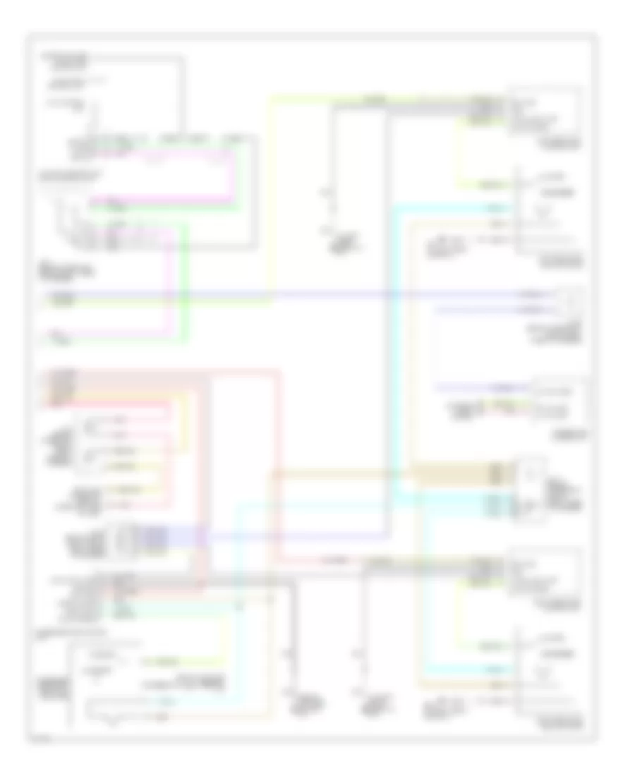
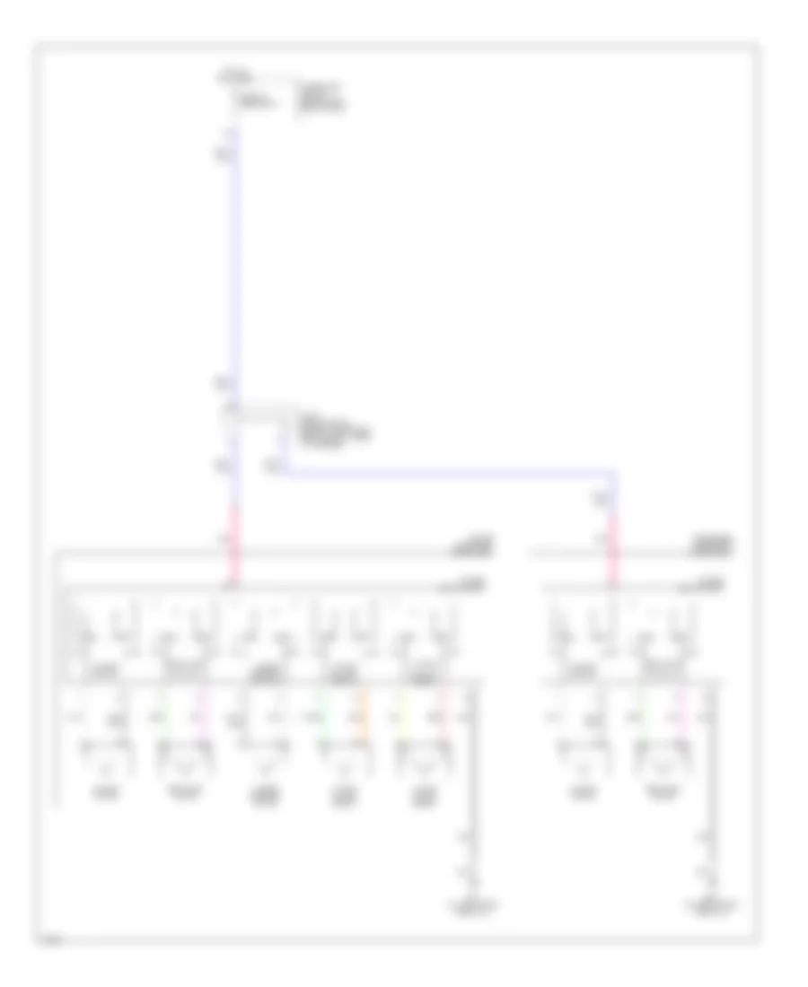
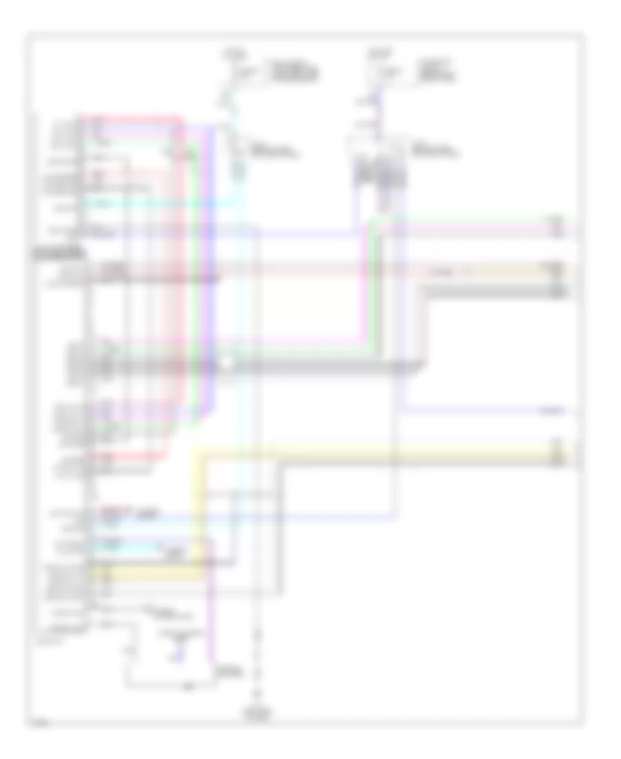
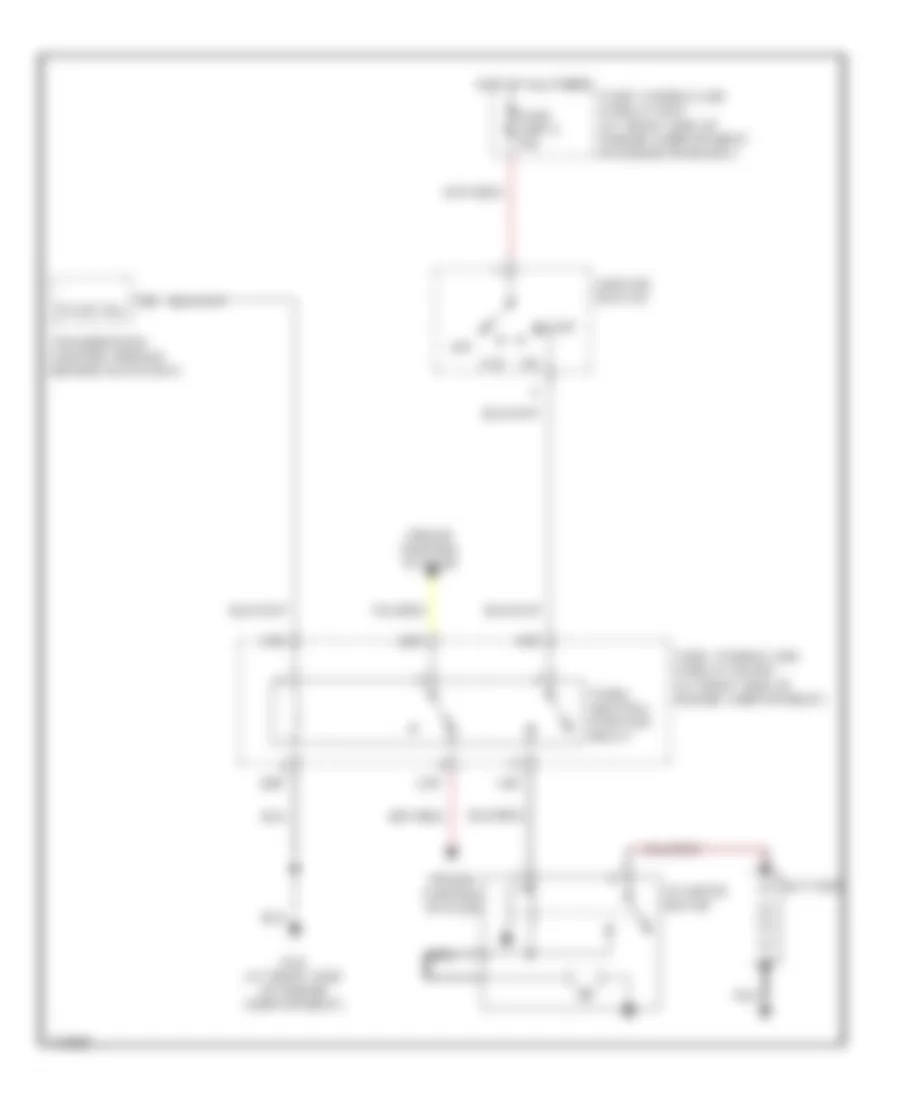
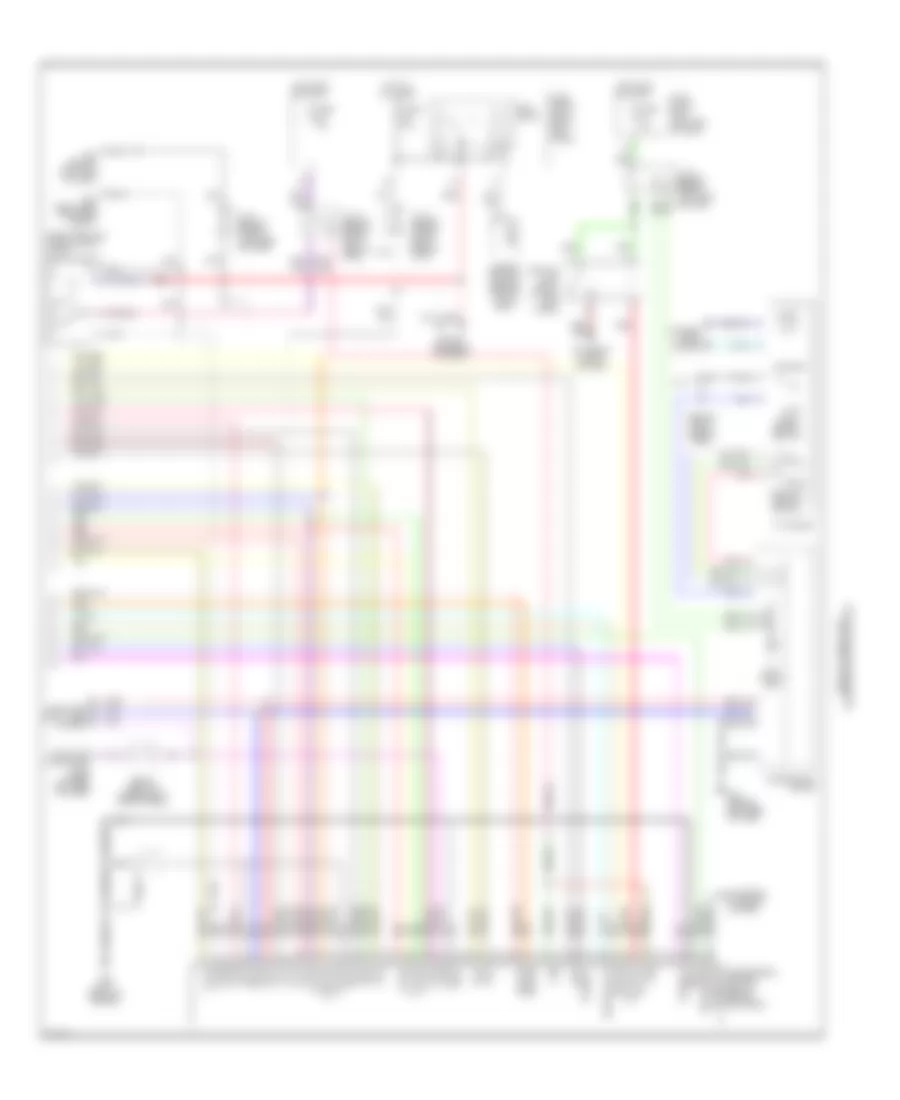
Automatic A/C Wiring Diagram (2 of 2) for Infiniti M45 2003
List of elements for Automatic A/C Wiring Diagram (2 of 2) for Infiniti M45 2003:
- (behind right side of dash) m114
- (behind right side of dash) m115
- 11r
- 18r
- Ac-av
- Acclk
- Acrly
- Air conditioner relay
- Air mix door motor (driver side)
- Av & navi control unit (or av control unit)
- Av-ac
- Avcc
- Blower motor (below right side of dash, on intake unit)
- Blower relay
- Bus +
- Bus -
- Bus shield
- Can-h
- Can-l
- Computer data lines system
- Connector used w/av & navi control unit
- Cooling fan speed control solenoid valve (on front of engine)
- Display
- Engine control module (behind glove box)
- Engine coolant temperature sensor (on top rear of engine)
- F101
- F102
- F8 (at left front of engine, near oil level gauge)
- Fuse 10a
- Fuse 15a
- Fuse block (j/b) 2 (behind right kick panel)
- Fuse, fusible link & relay block (j/b) (at right side of engine compartment)
- Gnd-a
- Heater & cooler unit assembly
- Hot at all times
- Intake sensor
- J/c 28 (behind upper right side of dash, near pass-through grommet)
- J/c 29 (behind upper right side of dash, near pass-through grommet)
- J/c 30 (behind upper right side of dash, near pass-through grommet)
- M115 (behind right side of dash)
- M144
- M145
- M83
- Mode door motor (driver side)
- Multifunction switch
- Nca
- Pdpres
- Pnk
- Prf+
- Prf-
- Radiator coolant temperature sensor (at bottom left side of radiator)
- Red
- Refrigerant pressure sensor (front right side of engine compartment, near condenser)
- Shield
- Twrf
- W/av & navi control unit
- W/av control unit
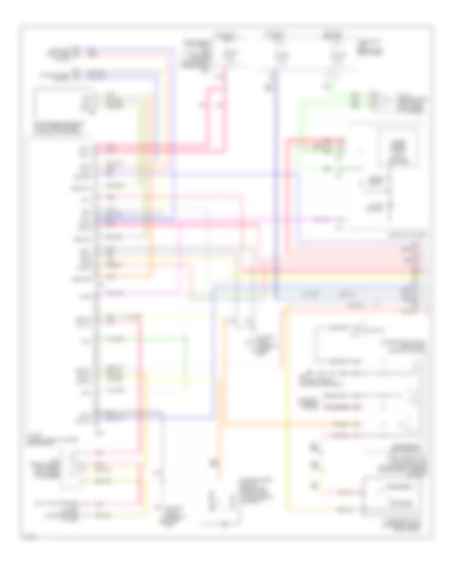
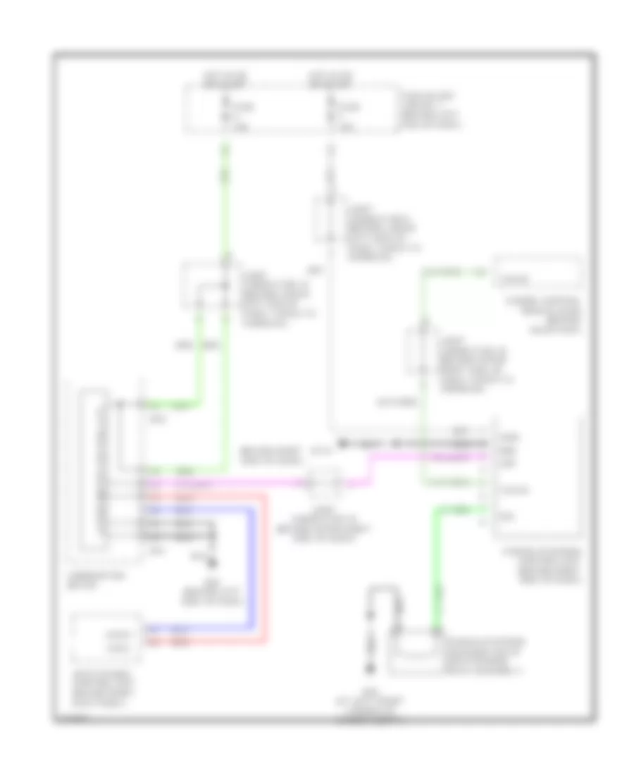
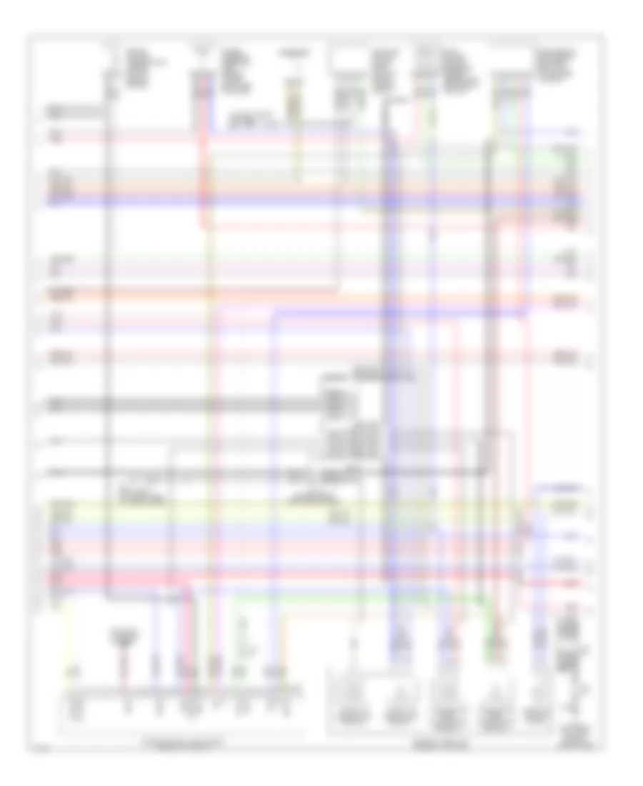
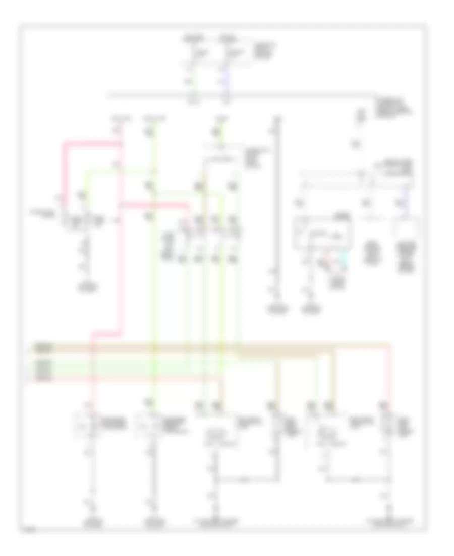
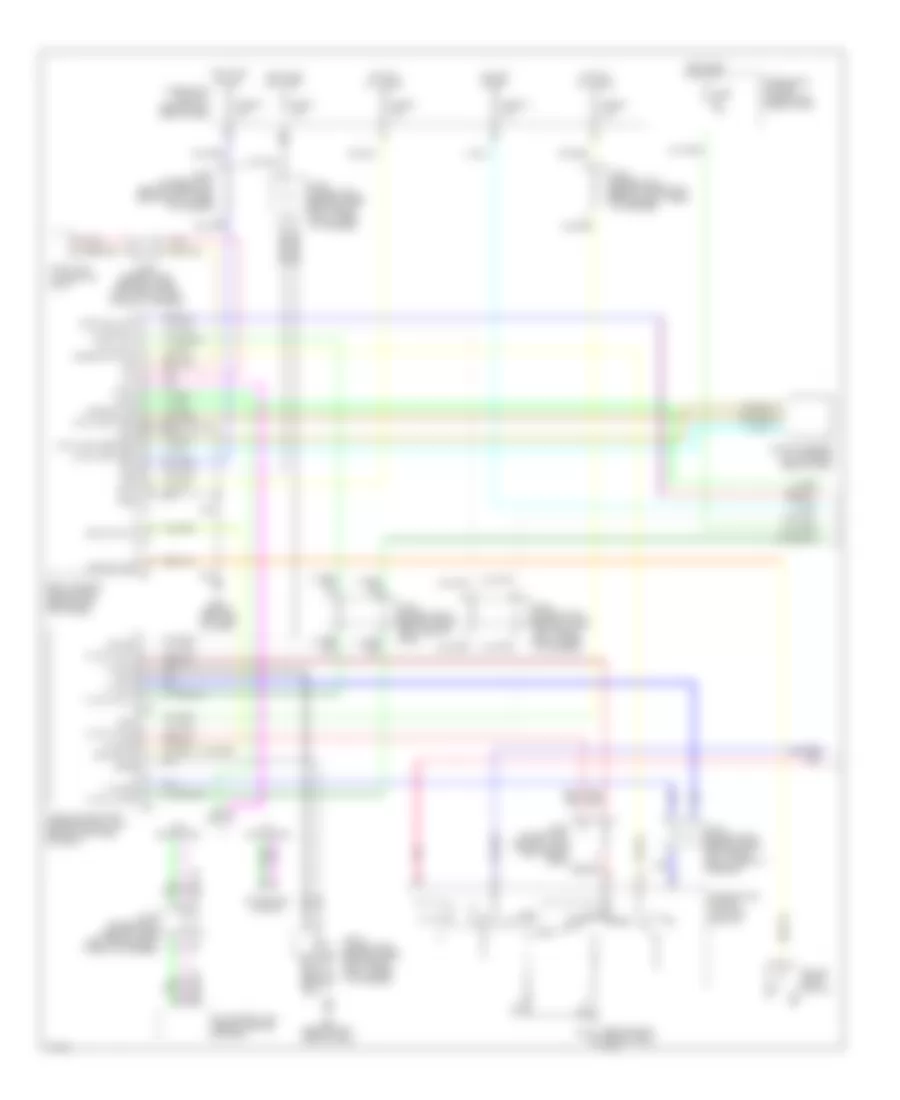
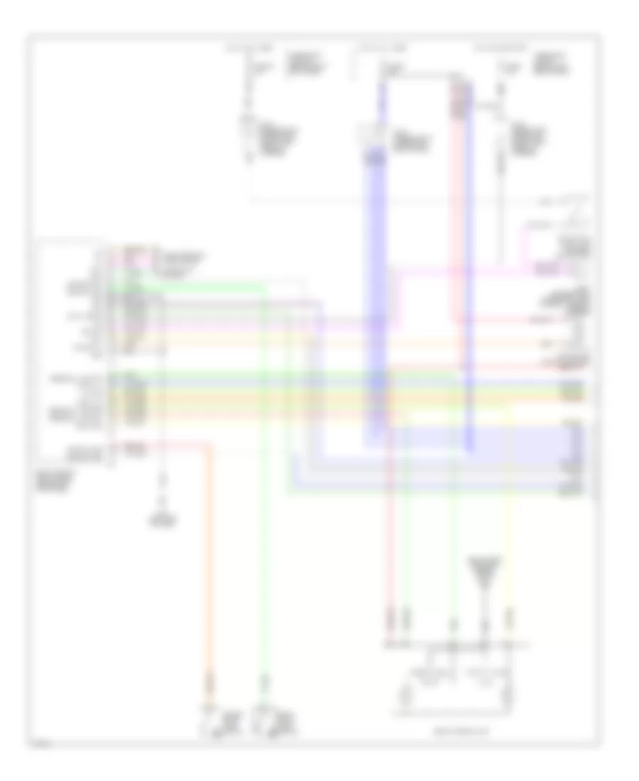
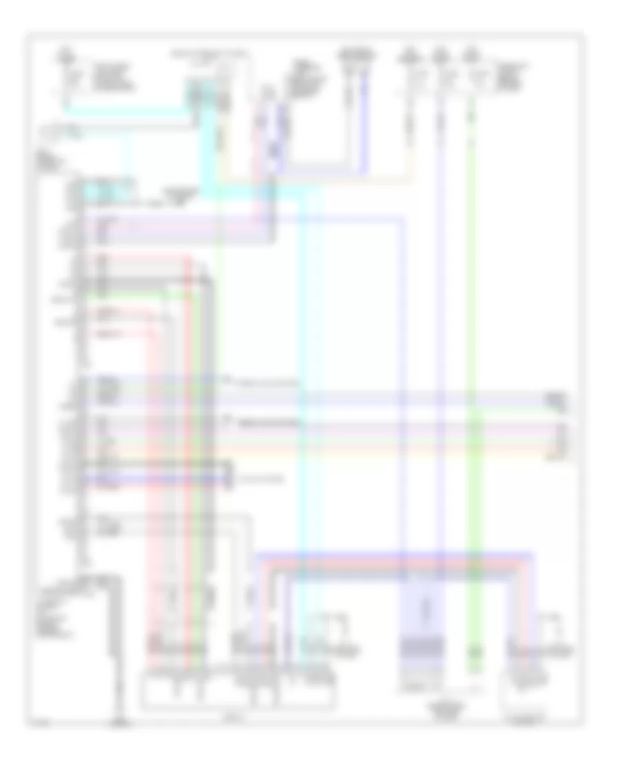
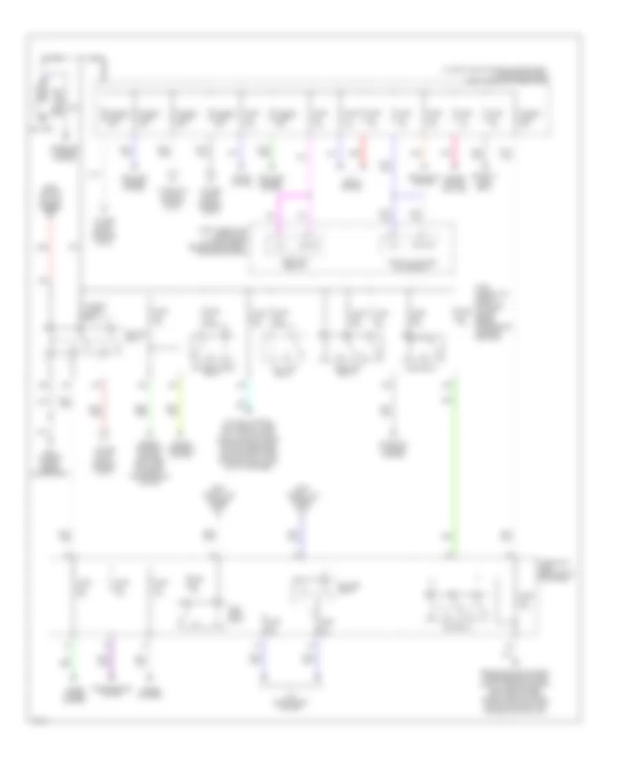
ANTI-LOCK BRAKES
Anti Lock Brake Wiring Diagram (1 of 2) for Infiniti M45 2003
List of elements for Anti Lock Brake Wiring Diagram (1 of 2) for Infiniti M45 2003:
- (near left strut tower) e67
- Abs w/l
- Ascd
- Ascd control unit (behind dash, left of steering col)
- B35
- Bls
- Can-h
- Can-l
- Computer data lines system
- Data link connector (under left side
- Fl mv-av
- Fl mv-ev
- Fl ss
- Fl ss gnd
- Fr mv-av
- Fr mv-ev
- Fr ss
- Fr ss gnd
- Fuse 17 15a
- Fuse 6 10a
- Fuse 7 10a
- Fuse 9 10a
- Fuse block no.1 (behind left end of dash)
- Gnd
- Gnd1
- Gnd2
- Hot at all times
- Hot in on or start
- J/c 10 (behind upper left side of dash)
- J/c 11 (behind top center of dash)
- J/c 7 (behind upper left side of dash)
- J/c 8 (behind upper left side of dash)
- J/c 9 (behind upper left side of dash)
- Left front wheel sensor
- Left rear wheel sensor
- Lis
- Of dash)
- Pkb sw
- Pnk
- Pressure sensor
- Pri usv
- Psm
- Pss
- Psu
- Red
- Right front wheel sensor
- Right rear wheel sensor
- Rl mv-av
- Rl mv-ev
- Rl ss
- Rl ss gnd
- Rr mv-av
- Rr mv-ev
- Rr ss
- Rr ss gnd
- Rxd
- Sec mav
- Sec usv
- Slip lamp
- Stop lamp switch (on bracket, above brake pedal)
- Tcs in
- Txd
- Vcc
- Vdc actuator (right rear of engine compartment)
- Vdc off lamp
- Vdc off sw
- Vdc/tcs/abs control unit (behind right kick panel)
- Vout
- W/o icc
- Yrsm
- Yrsrff
- Yrst
- Yrsu
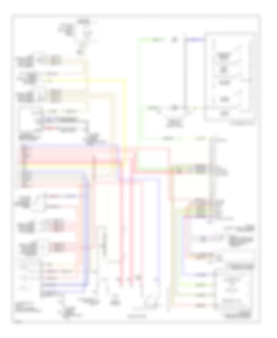
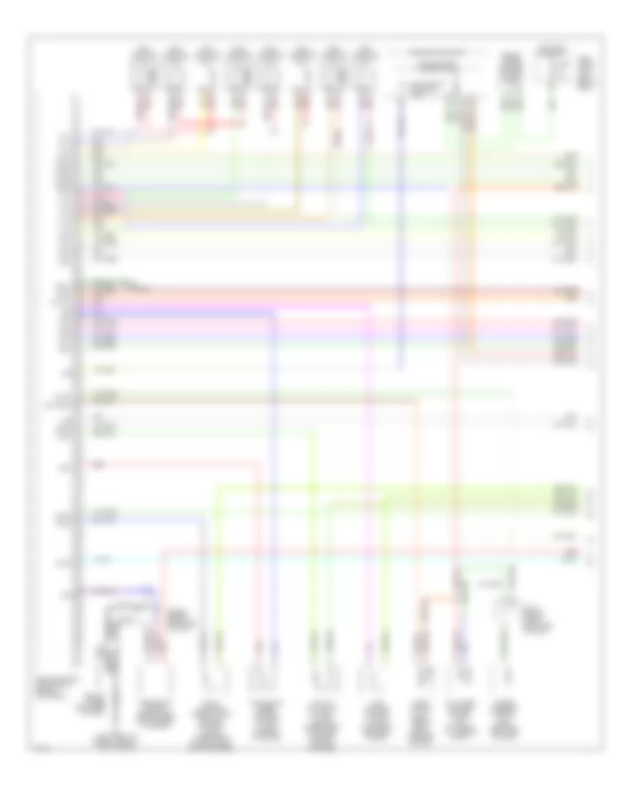
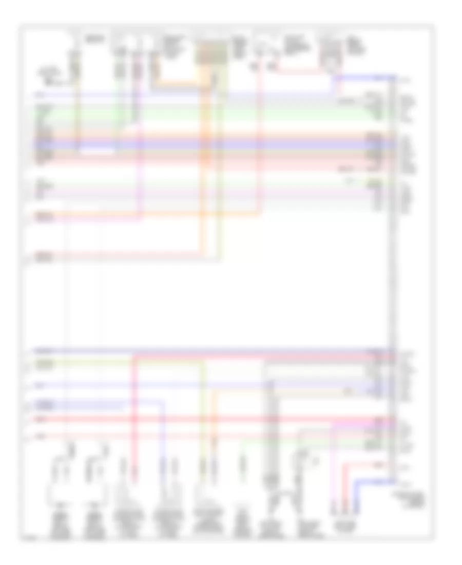
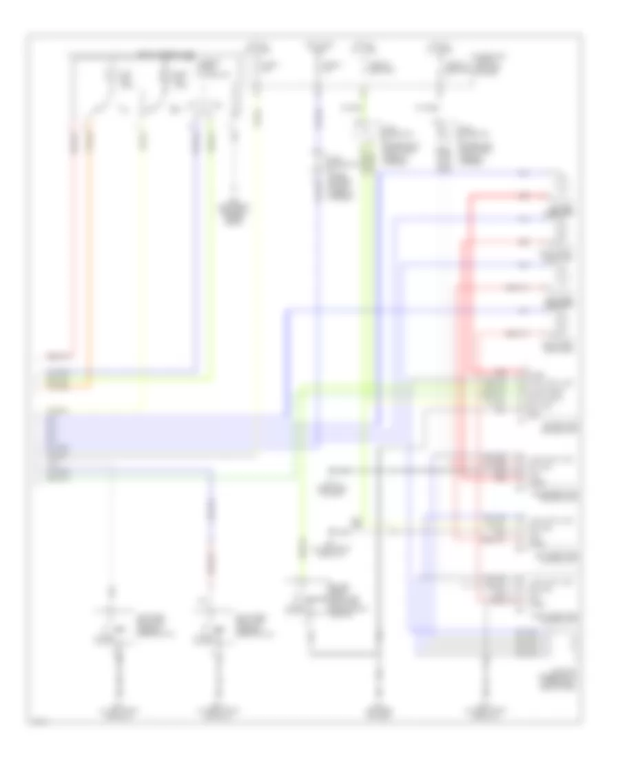
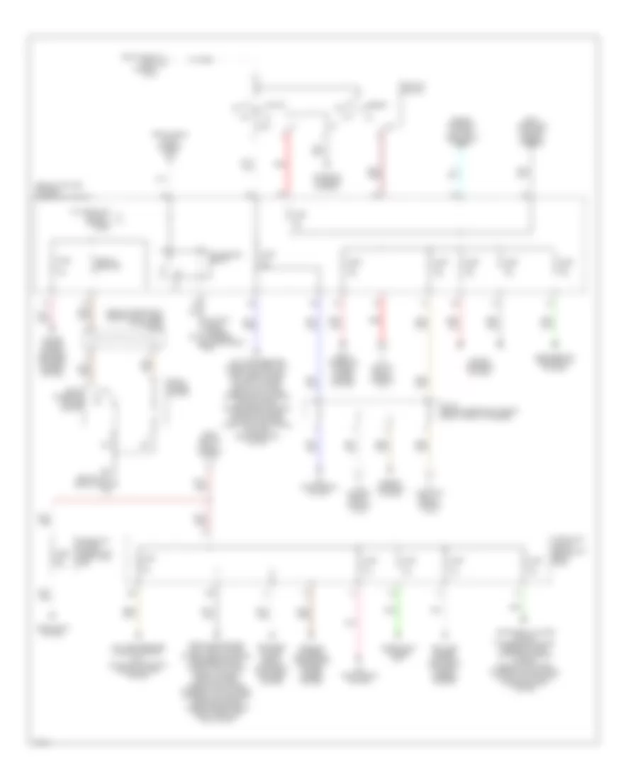
Anti Lock Brake Wiring Diagram (2 of 2) for Infiniti M45 2003
List of elements for Anti Lock Brake Wiring Diagram (2 of 2) for Infiniti M45 2003:
- (at right front corner of eng comp) e42
- (left side of dash) m24
- (left side of dash) m25
- 12v
- Abs
- Bite
- Brake fluid level switch (left rear of engine compt, on brake fluid reservoir)
- Bs out
- Can-h
- Can-l
- Combination meter
- Computer data lines system
- Drs out
- Fuse f 30a
- Fuse k 50a
- Fuse, fusible link & relay block (right front side of engine compt)
- Gnd
- Ground
- Hot at all times
- J/c 25 (behind lower left side of dash)
- J/c 3 (behind left side of dash)
- J/c 5 (behind upper left side of dash)
- Motor relay
- Parking brake switch (behind dash, at park brake assembly)
- Red
- Ref
- Slip
- Solenoid valve relay
- Steering wheel angle sensor
- Unified meter control unit
- Vdc off
- Vdc off switch (under left side of dash)
- Vdc relay box (behind front grille)
- Yaw rate and g sensor (under center console)
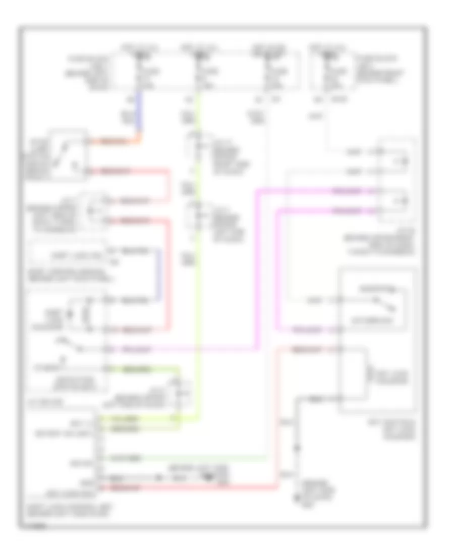
ANTI-THEFT
Anti-theft Wiring Diagram (1 of 2) for Infiniti M45 2003
List of elements for Anti-theft Wiring Diagram (1 of 2) for Infiniti M45 2003:
- (at right front door sill) b217
- (behind left side of dash) m24
- 13r
- 20b
- 25r
- Accessory
- B17 (at left front door sill)
- Battery
- Between full stroke & neutral
- Body control module (behind left kick panel)
- Closed
- Data line a-3
- Data out
- Door sw (as)
- Door sw (dr)
- Door sw (rl)
- Door sw (rr)
- E204
- Front door switch (driver side)
- Front door switch (passenger side)
- Fuse 10a
- Fuse 15a
- Fuse 20a
- Fuse block (j/b) 1 (behind left end of dash)
- Fuse, fusible link & relay block (j/b) (at right side of engine compartment)
- Fuse, fusible link & relay box (at right side of engine compartment, in engine room box)
- Ground
- Head- lamp relay
- Headlamp rly
- Headlights system
- Hood sw
- Horn chirp
- Hot at all times
- Hot in acc or on
- Hot in on or start
- Ignition
- J/c 10 (behind upper left end of dash, taped to harness)
- J/c 5 (behind upper left side of dash, taped to harness)
- J/c 9 (behind lower left side of dash, taped to harness)
- K/less gnd
- K/less power
- K/less signal
- Left rear door lock assembly (door switch)
- M1 4a
- Open
- Pnk
- Power
- Remote keyless entry receiver (at left "c" pillar)
- Right rear door lock assembly (door switch)
- Security horn (at right front engine compartment)
- Security horn relay (at left rear of engine compartment)
- Theft ind
- Trunk lid key cylinder switch (unlock switch)
- Trunk room lamp switch (at center rear of trunk lid)
- Trunk sw
- Trunk unlock sw
Anti-theft Wiring Diagram (2 of 2) for Infiniti M45 2003
List of elements for Anti-theft Wiring Diagram (2 of 2) for Infiniti M45 2003:
- (at left front door sill) b17
- (at right front corner of engine compartment) e42
- (at right front door sill) b217
- B17 (at left front door sill)
- B217 (at right front door sill)
- Bat (c/b)
- Between full stroke & n
- Circuit breaker
- Closed
- Data line a-3
- Driver door control unit (lcu01)
- Front door key cylinder switch (driver side)
- Front door lock actuator (driver side) (door unlock sensor)
- Front door lock actuator (passenger side) (door unlock sensor)
- Full stroke
- Fuse 10a
- Fuse block (j/b) 1 (behind left end of dash)
- Ground
- Hood switch (near hood lock stay)
- Hot at all times
- J/c 11 (behind upper right side of dash, taped to harness)
- J/c 15 (behind upper right side of dash, taped to harness)
- J/c 16 (behind upper right side of dash, taped to harness)
- J/c 21 (behind upper left side of dash, taped to harness)
- J/c 3 (behind upper left end of dash, taped to harness)
- Left rear door control unit
- Left rear door lock actuator (door unlock sensor)
- Local data line
- Lock
- Lock sw
- Locked
- M24 (behind left side of dash)
- Nca
- Open
- Passenger door control unit
- Right rear door control unit
- Right rear door lock actuator (door unlock sensor)
- Security indicator lamp
- Unlock
- Unlock sens
- Unlock sw
- Unlocked
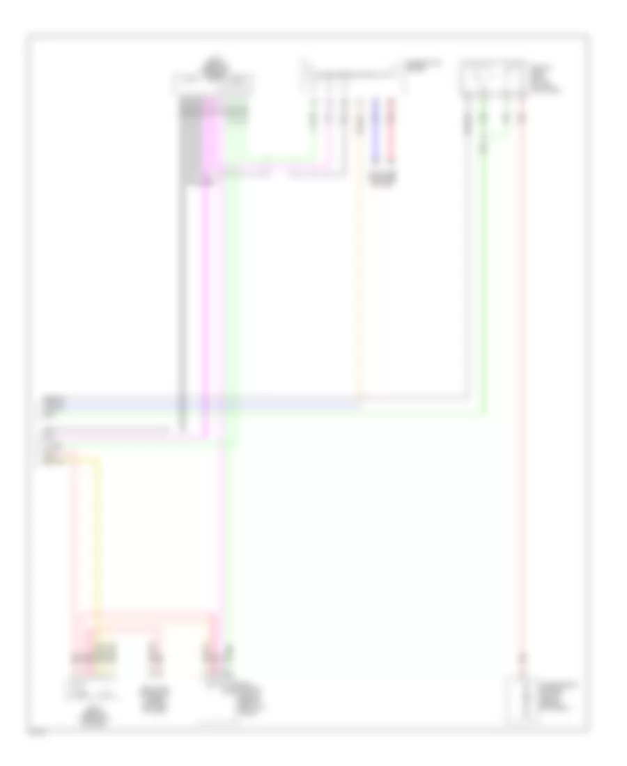
Immobilizer Wiring Diagram for Infiniti M45 2003
List of elements for Immobilizer Wiring Diagram for Infiniti M45 2003:
- (at left front of engine, near oil level gauge) f8
- (behind left side of dash) m25
- 20b
- Engine control module (behind glove box)
- F102
- Fuse 10a
- Fuse block (j/b) 1 (behind left end of dash)
- Fuse block j/b 2 (behind right kick panel)
- Hot at all times
- Hot in on or start
- Im line
- Inserted
- J/c 11 (behind upper right side of dash, taped to harness)
- J/c 16 (behind upper right side of dash, taped to harness)
- J/c 20 (behind upper right side of dash, taped to harness)
- J/c 29 (behind upper right side of dash, near pass-through grommet)
- J/c 3 (behind upper left end of dash, taped to harness)
- J/c 5 (behind upper left side of dash, taped to harness)
- Key switch & key lock solenoid (key switch)
- M145
- Nats antenna amplifier (behind lower left side of dash)
- Nats immu (behind dash, left of steering column)
- Red
- Security indicator lamp
- Steering lock control unit (behind center of dash)
- Withdrawn
BODY CONTROL MODULES
Body Computer Module Wiring Diagram (1 of 2) for Infiniti M45 2003
List of elements for Body Computer Module Wiring Diagram (1 of 2) for Infiniti M45 2003:
- tilt sw (down)
- Acc
- Auto sens
- Auto sens (5v)
- Auto sens (gnd)
- Body control module (bcm) (left kick panel)
- Chime
- Combo sw (auto)
- Data link connector (under left side of dash)
- Defog sw
- Defogger system
- Detent sw (key)
- Door locks system
- Door sw (as)
- Door sw (rl)
- Exterior lights system
- Flasher
- Fuse 14 10a
- Fuse 21 10a
- Fuse block no. 1 (left end of dash)
- Gnd
- Hdlt relay
- Headlights system
- Hot in accy or on
- Hot in start
- Iiurx
- Iiutx
- Ill out
- Instrument cluster system
- Int (vr)
- Interior lights system
- Joint connector 3 (behind upper left side of dash)
- Joint connector 8 (behind lower left side of dash)
- K/less gnd
- K/less pwr (5v)
- K/less sig
- Light sw (1st)
- M24 (left side of dash)
- Memory sw 1
- Memory sw 2
- Memory system
- Memory systems
- Mirror sw down
- Mirror sw left
- Mirror sw right
- Mirror sw up
- Mirrors system
- Navigation system
- Pnk
- Red
- Select sw lh
- Select sw rh
- Set sw
- Shift interlock system
- Shift lock sol
- Speed sig
- Tail relay
- Telesco sw (fr)
- Telesco sw (rr)
- Tilt sens
- Tilt sw (up)
- Tilt tele ss gnd
- Tilt/tele sen pwr
- Warning systems
- Wiper sw (int)
- Wiper sw (wash)
- Wiper/washer system
Body Computer Module Wiring Diagram (2 of 2) for Infiniti M45 2003
List of elements for Body Computer Module Wiring Diagram (2 of 2) for Infiniti M45 2003:
- 20b
- All off
- Anti-theft system
- Batt
- Body control module (bcm) (left kick panel)
- Circuit breaker 1
- Computer data lines system
- Data line a-1
- Data line a2
- Data line a3
- Defogger system
- Door locks system
- Door sw (dr)
- Door sw (rr)
- Door warn lmp
- E204
- Exterior lights system
- Fuse 1 10a
- Fuse 3 10a
- Fuse block no. 1 (behind left kick panel)
- Gnd
- Headlamp battery saver control unit
- Hood sw
- Horn chirp
- Horn system
- Hot at all times
- Hot in on or start
- Ign
- Ign key ill
- Instrument cluster system
- Interior lights system
- Joint connector 3 (behind left side of dash, near fuse block)
- Key switch
- M24 (left side of dash)
- Map/l (lh)
- Map/l (rh)
- Mem ind 2
- Memory ind 1
- Memory systems
- Personal lmp sw
- Pnk
- Rap output
- Rev-lmp sw
- Rl personal lmp (rl)
- Rr def
- Rr personal lmp
- Seat belt sw (dr)
- Tele motor (fr)
- Tele motor (rr)
- Telesco sens
- Theft ind
- Tilt motor (down)
- Tilt motor (up)
- Tilt tele batt
- Tilt tele gnd
- Total ill
- Trunk opener
- Trunk opener sw
- Trunk sw
- Trunk unlock sw
- Trunk, tailgate, fuel doors system
- Warning system
- Wiper amp
- Wiper auto stop
- Wiper/washer system
COMPUTER DATA LINES
Computer Data Lines Wiring Diagram for Infiniti M45 2003
List of elements for Computer Data Lines Wiring Diagram for Infiniti M45 2003:
- (at left front of engine near oil level gauge) f8
- (behind left end of dash)
- (behind left side of dash) m25
- (not used)
- (under left side of dash)
- 33r
- Air bag diagnosis sensor unit (under rear of center console)
- Ascd control unit (behind dash, left of steering column)
- Av control unit (w/o navigation) (1:) av & navi control unit (w/ navigation) (2:) (1: behind center of dash) (2: center of luggage compartment)
- Av-cn
- B143
- B243
- B244
- B29
- Body control module (behind left kick panel)
- Can-h
- Can-l
- Cn-av
- Combination meter
- D38
- D58
- D78
- Data line a1
- Data line a2
- Data line a3
- Data link connector
- Ddl-rx
- Ddl-tx
- Driver door control unit (lcu01)
- Driver seat control unit (lcu02)
- Driver side door mirror control unit (lcu03)
- Engine control module (behind glove box)
- F102
- F103
- Front power seat (driver side)
- Fuse 58 10a
- Fuse 6 10a
- Fuse block (j/b) 1
- Fuse, fusible link & relay block (j/b) (at right side of engine compartment)
- Hot at all times
- Hot in on or start
- Icc sensor (behind center of front bumper)
- Icc unit (on right side of luggage compartment)
- If equipped
- J/c 11 (behind upper right side of dash, taped to harness)
- J/c 15 (behind upper right side of dash, taped to harness)
- J/c 29 (behind upper right side of dash, near pass through grommet)
- J/c 5 (behind upper left side of dash, taped to harness)
- J/c 8 (behind lower left side of dash, taped to harness)
- K-line
- Kline
- Left rear door control unit
- Local data line
- M103
- M35
- M41
- M77
- Non dtc
- Passenger door control unit
- Passenger side door mirror control unit (lcu04)
- Pnk
- Red
- Right rear door control unit
- Rxd
- Rxi
- Steering angle sensor (under left side of dash, right of steering column)
- Transmission control control module (behind glove box)
- Txd
- Txi
- Unified meter control unit
- Vdc/tcs/abs control unit (behind right kick panel)
- W/ navigation
- W/o navigation
CRUISE CONTROL
Cruise Control Wiring Diagram for Infiniti M45 2003
List of elements for Cruise Control Wiring Diagram for Infiniti M45 2003:
- 14r
- 15r
- 21r
- 24r
- 29r
- 31r
- A solenoid monitor input
- Actr output high side
- Air valve
- Air valve output low side
- Ascd
- Ascd brake switch (on bracket, above brake pedal)
- Ascd control unit (behind dash, left of steering column)
- Ascd pump (at right rear corner of engine compartment)
- Ascd steering switch
- Brake nc sw input
- Brake no sw input
- Cancel switch
- Combination meter
- Combination switch (spiral cable)
- Control sw ad input
- Control sw gnd input
- Cruise (green)
- Cruise lamp output
- Data link connector (partial) (under left side
- Depre- ssed
- Depressed
- E24 (at right side of engine compartment)
- Ecm prun input
- Engine control module (behind glove box)
- Etc prun
- F101
- F102
- F104
- F8 (at left front of engine, near oil level gauge)
- Fuse 10a
- Fuse 15a
- Fuse block (j/b) 1 (behind left end of dash)
- Fuse, fusible link & relay block (j/b) (at right side of engine compartment, in engine room box)
- Gnd
- Gnd-c
- Hot at all times
- Hot in on or start
- Ign sw
- J/c 10 (behind upper left end of dash, taped to harness)
- J/c 16 (behind upper right side of dash, taped to harness)
- J/c 5 (behind upper left side of dash, taped to harness)
- J/c 7 (behind upper left side of dash, taped to harness)
- J/c 8 (behind lower left side of dash, taped to harness)
- M25 (behind left side of dash)
- M41
- M42
- M441
- M53
- Main (cruise) switch
- Od cancel signal
- Of dash)
- Off
- Park/neutral position relay
- Pnk
- Release valve
- Release valve out low side
- Released
- Resume/ accel switch
- Rxi
- Set
- Set lamp output
- Set/ coast switch
- Start rly
- Starting/ charging system
- Stoplamp switch (on bracket, above brake pedal)
- Tcs input
- Throttle position input
- Transmission control module (tcm) (behind glove box)
- Tvoo
- Txi
- Unified meter control unit
- Vacuum motor
- Vacuum mtr out low side
- Vdc/tcs/abs control unit (behind right kick panel)
- Vehicle speed input
Intelligent Cruise Control Wiring Diagram (1 of 2) for Infiniti M45 2003
List of elements for Intelligent Cruise Control Wiring Diagram (1 of 2) for Infiniti M45 2003:
- 14r
- 15r
- 21r
- 24r
- 29r
- 31r
- B243
- B244
- Bat-1
- Bat-2
- Bnc-sw
- Bno-sw
- Brake pressure sensor (at left rear corner of engine compartment)
- Buzz
- Can-h
- Can-l
- Combination meter
- Computer data lines system
- Corner of trunk) b257
- Cruise (green)
- Data link connector (dlc) (partial) (under left side of dash)
- Ddl-rx
- Ddl-tx
- Depressed
- E24 (at right side of engine compartment)
- F104
- Fuse 10a
- Fuse 15a
- Fuse block (j/b) 1 (behind left end of dash)
- Fuse, fusible link & relay block (j/b) (at right side of engine compartment, in engine room box)
- Fuse, fusible link & relay box (at right side of engine compartment, in engine room box)
- Gnd
- Gnd-1
- Gnd-2
- Gnd-3
- Hot at all times
- Hot in on or start
- Icc brake switch (on bracket, above brake pedal)
- Icc unit (on right side of luggage compartment)
- Ign-1
- Ign-2
- J/c 10 (behind upper left end of dash, taped to harness)
- J/c 8 (behind lower left side of dash, taped to harness)
- M41
- M42
- Park/neutral position relay
- Parking brake switch (behind left side of dash, at park brake assembly)
- Pkb sw
- Pnk
- Psen-gnd
- Psen-pwr
- Psen-sig
- Red
- Released
- Rls-nc
- Rls-no
- Rls-pwr
- Sol+
- Sol-
- Start rly
- Starting/ charging system
- Stp-lmp
- Transmission control module (tcm) (behind glove box)
- Unified meter control unit (with icc indicator)
- Vout
- Vpwr
- Warn
- Wip-h
- Wip-l
- Wiper/washer system
Intelligent Cruise Control Wiring Diagram (2 of 2) for Infiniti M45 2003
List of elements for Intelligent Cruise Control Wiring Diagram (2 of 2) for Infiniti M45 2003:
- (at right front door sill) b217
- (at right side of engine compartment) e24
- 19b
- Accelerate/ resume switch
- Air valve
- Ascd pump (at right rear corner of engine compartment)
- B245
- Boost solenoid
- Brake booster
- Can-h
- Can-l
- Cancel switch
- Coast/ set switch
- Combination switch (spiral cable)
- Computer data lines system
- Cruise
- Distance switch
- Engine control module (behind glove box)
- F102
- Fuse 10a
- Fuse block (j/b) 1 (behind left end of dash)
- Gnd
- Gnd-a
- Gnd-s
- Hot in on or start
- Icc brake hold relay (at left rear of engine compartment)
- Icc sensor (behind center of front bumper)
- Icc steering switch
- Icc unit (on right side of luggage compartment)
- Icc warning chime (below lower left side of dash)
- Ignition
- J/c 1 (behind upper left end of dash, taped to harness)
- J/c 25 (behind lower left side of dash, near pass-through grommet)
- J/c 3 (behind upper left end of dash, taped to harness)
- J/c 30 (behind upper right side of dash, near pass-through grommet)
- J/c 7 (behind upper left side of dash, taped to harness)
- M441
- M53
- Nca
- Od-cancel
- On/off switch
- Pnk
- Red
- Release valve
- Safty
- Stoplamp switch (on bracket, above brake pedal)
- Strg gnd
- Strg sig
- T-rly
- Tvo
- Tvoo
- Vacuum motor
- Vent
DEFOGGERS
Defoggers Wiring Diagram for Infiniti M45 2003
List of elements for Defoggers Wiring Diagram for Infiniti M45 2003:
- (behind left side of dash) m24
- (behind right side of dash) m114
- 20b
- B17 (at left front door sill)
- B181
- B421
- B422 (at right "c" pillar)
- Battery
- Body control module (behind left kick panel)
- Condenser
- Def sw
- Door mirror defogger relay (at left kick panel)
- Driver side door mirror defogger
- Fuse 10a
- Fuse 20a
- Fuse block j/b 1 (behind left end of dash)
- Gnd
- Hot at all times
- Hot in acc or on
- Hot in on or start
- Ignition
- J/c 19 (behind upper right side of dash, taped to harness)
- J/c 2 (behind upper left side of dash, taped to harness)
- J/c 5 (behind upper left side of dash, taped to harness)
- M114 (behind right side of dash)
- Multifunction switch
- Passenger side door mirror defogger
- Rear window defogger
- Rear window defogger & door mirror defogger relay (behind left kick panel)
- Rr def
- Rr def f/b
- Rr def on
ELECTRONIC MUFFLER
Electronic Muffler Wiring Diagram for Infiniti M45 2003
List of elements for Electronic Muffler Wiring Diagram for Infiniti M45 2003:
- (behind upper right side of dash) joint connector 19
- B256 (at right front corner of trunk)
- Close output
- Dual mode muffler actuator (at left rear of vehicle)
- Dual mode muffler control unit (at right side of luggage compartment)
- Engine control module (ecm) (behind glove box)
- Fuse 1 10a
- Fuse block (j/b) no. 1 (behind left end of dash)
- Ground
- Hot in on or start
- Ignition
- Open output
- Tachometer
- Tvo0
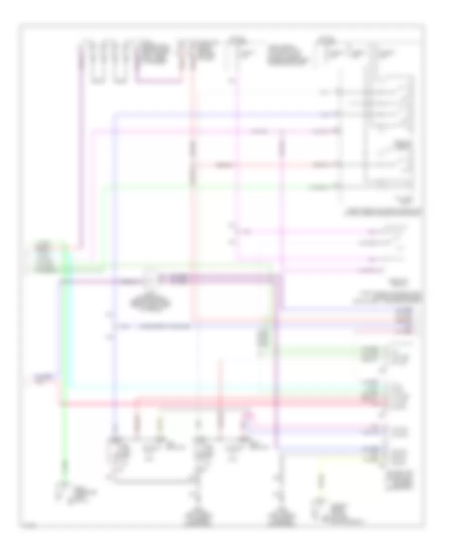
ELECTRONIC POWER STEERING
Electronic Power Steering Wiring Diagram for Infiniti M45 2003
List of elements for Electronic Power Steering Wiring Diagram for Infiniti M45 2003:
- (behind right side of dash)
- Can-h
- Can-l
- Combination meter
- E62 (at left front corner of engine compt)
- Engine control module (ecm) (behind glove box)
- Fuse 10a
- Fuse block (j/b) no. 1 (behind left end of dash)
- Gnd
- Hot in on or start
- Joint connector 10 (behind upper left end of dash, taped to harness)
- Joint connector 16 (behind upper right side of dash)
- Joint connector 19 (behind upper right side of dash, taped to harness)
- Joint connector 9 (behind lower left side of dash, taped to harness)
- M114
- M24 (behind left side of dash)
- M41
- M42
- Power steering control unit (behind right side of dash)
- Power steering solenoid valve (on steering rack assembly)
- Red
- Sol
- Tacho
- Unified meter control unit
- Vdc/tcs/abs control unit (behind right kick panel)
- Vign
- Vsp
ENGINE PERFORMANCE
4.5L
4.5L, Engine Performance Wiring Diagram (1 of 5) for Infiniti M45 2003
List of elements for 4.5L, Engine Performance Wiring Diagram (1 of 5) for Infiniti M45 2003:
- (behind upper left end of dash) j/c 10
- (behind upper right side of dash)
- A/c system
- Acrly
- Ascd control unit (behind dash, left of steering column)
- Combination meter
- Cooling fan speed control solenoid valve (on front of engine)
- Crankshaft position sensor (pos) (bottom rear of engine)
- Crtn
- Cvbv
- Dual mode muffler control unit (at right of luggage compt)
- Engine control module (ecm) (behind glove box)
- Etc prun
- Evap
- Evap canister purge volume control solenoid valve (under rear of vehicle, on evap canister)
- F8 (left front of engine, near oil level gauge)
- Fpcm
- Fpr
- Fuel injector
- Fuse 10a
- Fuse block (j/b) 1 (left end of dash)
- Hot in on or start
- Ign 1
- Ign 2
- Ign 3
- Ign 4
- Ign 5
- Ign 6
- Ign 7
- Ign 8
- Ignsw
- Inj 1
- Inj 2
- Inj 3
- Inj 4
- Inj 5
- Inj 6
- Inj 7
- Inj 8
- J/c
- J/c 19 (behind upper right side of dash)
- J/c 28
- Led
- Malfunction indicator lamp
- Motrly
- Nca
- O2hfl
- O2hfr
- O2hrl
- O2hrr
- Pnk
- Pos
- Power steering control unit (behind right side of dash)
- Prf+
- Prf-
- Prun in
- Red
- Ssoff
- Stsw
- Tacho
- Tp in
- Tvo0
- Unified meter control unit
- Vacuum cut valve bypass valve (under rear of vehicle, forward of evap canister)
- Vias
- Vias control solenoid valve (top front center of engine)
4.5L, Engine Performance Wiring Diagram (2 of 5) for Infiniti M45 2003
List of elements for 4.5L, Engine Performance Wiring Diagram (2 of 5) for Infiniti M45 2003:
- (behind upper right side of dash) j/c 19
- 22r
- Condenser
- Ecm relay
- F8 (left front of engine, near oil level gauge)
- F9 (left front of engine, near oil level gauge)
- Fuse 10a
- Fuse 15a
- Fuse 20a
- Fuse block (j/b) 1 (left end of dash)
- Fuse block (j/b) 2 (right kick panel)
- Fuse, fusible link & relay block (j/b) (in right front side of engine compt)
- Hot at all times
- Hot in on or start
- Hot in start
- Ignition coil 1 (w/ power transistor)
- Ignition coil 2 (w/ power transistor)
- Ignition coil 3 (w/ power transistor)
- Ignition coil 4 (w/ power transistor)
- Ignition coil 5 (w/ power transistor)
- Ignition coil 6 (w/ power transistor)
- Ignition coil 7 (w/ power transistor)
- Ignition coil 8 (w/ power transistor)
- Nca
- Plug spark
- Red
- Spark plug
- Throttle control motor relay
4.5L, Engine Performance Wiring Diagram (3 of 5) for Infiniti M45 2003
List of elements for 4.5L, Engine Performance Wiring Diagram (3 of 5) for Infiniti M45 2003:
- (behind upper right side of dash) j/c 30
- 33r
- 34r
- Camshaft position sensor (phase) (on front of left cyl head)
- F8 (left front of engine, near oil level gauge)
- Fuel pump relay
- Fuse 10a
- Fuse 15a
- Fuse block (j/b) 1 (left end of dash)
- Fuse block (j/b) 2 (right kick panel)
- Fuse, fusible link & relay block (j/b) (in right front side of engine compt)
- Heated oxygen sensor 1 (bank 1) (on inlet of left manifold twc)
- Heated oxygen sensor 1 (bank 2) (on inlet of right manifold twc)
- Heated oxygen sensor 2 (bank 1) (on outlet of left manifold twc)
- Heated oxygen sensor 2 (bank 2) (on outlet of right manifold twc)
- Hot at all times
- Hot in on or start
- Intake valve timing control position sensor (bank 1) (on front of left cyl head)
- Intake valve timing control position sensor (bank 2) (on front of right cyl head)
- J/c
- Nca
- Pnk
- Radiator coolant temperature sensor (bottom left side of radiator)
- Red
- Refrigerant pressure sensor (front right side of engine compt, near condenser)
4.5L, Engine Performance Wiring Diagram (4 of 5) for Infiniti M45 2003
List of elements for 4.5L, Engine Performance Wiring Diagram (4 of 5) for Infiniti M45 2003:
- (at right front door sill) b217
- Accelerator pedal position (app) sensor 1
- Accelerator pedal position (app) sensor 2
- Aps1
- Avcc2
- Batt
- Condenser
- Electric throttle control actuator
- Engine control module (ecm) (behind glove box)
- Engine coolant temperature sensor (on top rear of engine)
- Evap control system pressure sensor (under right rear side of vehicle)
- F8 (left front of engine, near oil level gauge)
- Fuel pump control module (fpcm) (on right side of luggage compt)
- Gnd a
- Gnd a2
- Ivcpusl
- Ivcpusr
- J/c
- J/c 28
- J/c 29 (behind upper right side of dash)
- Mass airflow (maf) sensor (between air duct & air cleaner housing)
- Nca
- Neut
- Pdpres
- Phase
- Pnk
- Power steering pressure (psp) sensor (lower right side of engine)
- Qa+
- Red
- Starting/ charging system
- Throttle control motor
- Throttle position (tp) sensor 1
- Throttle position (tp) sensor 2
- Tps2
4.5L, Engine Performance Wiring Diagram (5 of 5) for Infiniti M45 2003
List of elements for 4.5L, Engine Performance Wiring Diagram (5 of 5) for Infiniti M45 2003:
- (at left front door sill) b17
- Aps2
- Avcc
- Brksw
- Can h
- Can l
- Cdcv
- Computer data lines system
- Dropping resistor
- Engine control module (ecm) (behind glove box)
- Evap canister vent control valve (under rear of vehicle, on evap canister)
- F8 (left front of engine,
- F9 (left front of engine,
- Fgauge+
- Fgauge-
- Fpcmck
- Ftprs
- Fuel level sensor unit & fuel pump (in fuel tank)
- Gnd c
- Gnd e
- Gnd m
- Im lime
- Intake valve timing control solenoid valve (bank 1) (on top front of left cyl head)
- Intake valve timing control solenoid valve (bank 2) (on top front of right cyl head)
- Ivcl
- Ivcr
- J/c
- J/c 15 (behind upper right side of dash)
- J/c 7 (behind upper left side of dash)
- Kline
- Knk1
- Knk2
- Knock sensor (bank 1) (below left side of intake manifold)
- Knock sensor (bank 2) (below right side of intake manifold)
- Motor 1
- Motor 2
- Nats immu (behind dash, left of steering column)
- Nca
- Near oil level gauge)
- O2sfl
- O2sfr
- O2srl
- O2srr
- Pnk
- Pspres
- Qa-
- Red
- Stop lamp switch (on bracket, above brake pedal)
- Tps1
- Tvo0
- Twrf
- Vmot
EXTERIOR LIGHTS
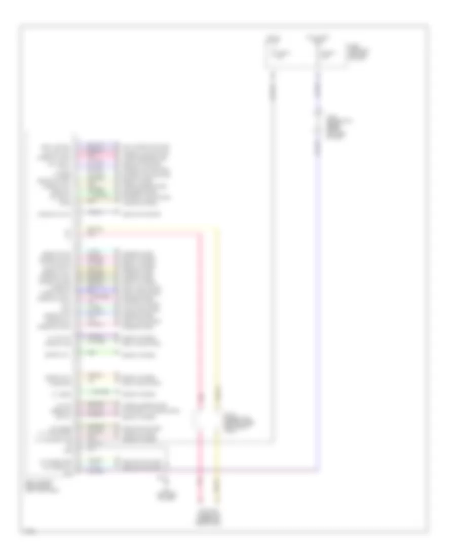
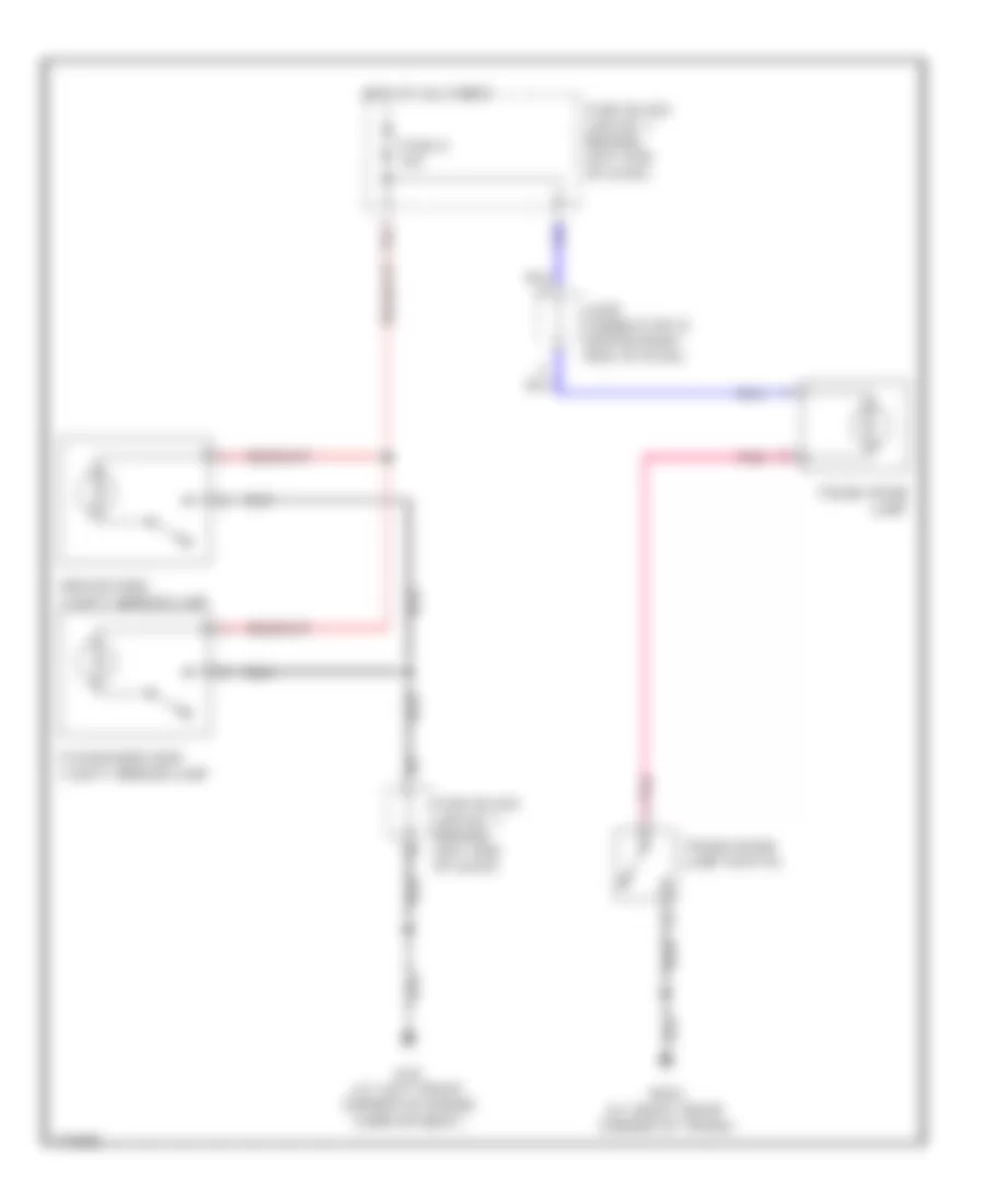
Back-up Lamps Wiring Diagram for Infiniti M45 2003
List of elements for Back-up Lamps Wiring Diagram for Infiniti M45 2003:
- B57 (center rear of trunk)
- Back- up
- Back-up lamp relay
- Back-up lamp relay (at left kick panel)
- Fuse 10a
- Fuse block (j/b) no. 1 (left end of dash)
- Hot in on or start
- Joint conector 10 (behind upper left end of dash, taped to harness)
- Left rear combination lamp
- Red
- Right rear combination lamp
- Transmission control module (tmc) (behind glove box)
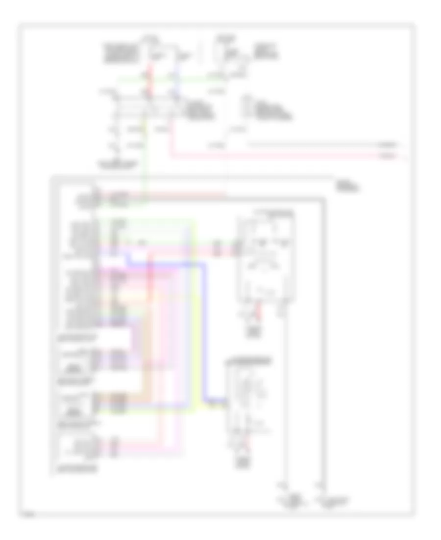
Exterior Lights Wiring Diagram (1 of 2) for Infiniti M45 2003
List of elements for Exterior Lights Wiring Diagram (1 of 2) for Infiniti M45 2003:
- 12r
- 1st
- 20b
- 26r
- 2nd
- Auto
- B217 (at right front door sill)
- B256 (at right front corner of trunk)
- B57 (center rear of trunk)
- Bat
- Body control module (bcm) (left kick panel)
- Comb sw
- Combi- nation switch (lighting switch)
- Door sw
- Driver side front door switch
- Fuse 1 10a
- Fuse 17 15a
- Fuse 54 15a
- Fuse 6 10a
- Fuse block (j/b) no. 1 (left end of dash)
- Fuse, fusible link & relay block (j/b) (at right side of engine compt)
- Gnd 1
- Gnd 2
- H/l rly
- H/l sw
- Headlamp battery saver control unit (behind left side of dash)
- Headlights system
- High- mounted stop lamp
- Hot at all times
- Hot in on or start
- Ign sw
- Joint connector (behind upper left side of dash)
- Joint connector (behind upper right side of dash)
- Joint connector 13 (behind upper right side of dash)
- Joint connector 21 (behind upper left side of dash)
- Joint connector 25 (behind lower left side of dash, near pass through grommet)
- Joint connector 5 (behind upper left side of dash)
- Joint connector 7 (behind upper left side of dash)
- Left license lamp
- Left rear combination lamp
- Left rear side marker lamp
- M115 (right side of dash)
- M25 (left side of dash)
- Nca
- Off
- Passenger side front door switch
- Rap in
- Rap out
- Right license lamp
- Right rear combination lamp
- Right rear side marker lamp
- Stop
- Stop lamp switch (on bracket, above brake pedal)
- T/l rly
- T/l rly 1
- T/l rly 2
- T/l sw
- Tail
- Tail lamp relay
- Turn
Exterior Lights Wiring Diagram (2 of 2) for Infiniti M45 2003
List of elements for Exterior Lights Wiring Diagram (2 of 2) for Infiniti M45 2003:
- (behind upper right side of dash) joint connector 20
- 10b
- 11b
- 17b
- 18b
- Bat
- Body control module (bcm) (left kick panel)
- Combination flasher unit (behind lower front of center console)
- Combination meter
- Combination switch (turn signal switch)
- Driver side door mirror (turn signal)
- E42 (at right front corner of engine compt)
- E62 (at left front corner of engine compt)
- Fuse 22 15a
- Fuse 5 10a
- Fuse block (j/b) no. 1 (left end of dash)
- Gnd
- Haz sw & bcm
- Hazard
- Hazard switch
- Hot at all times
- Hot in on or start
- Ign sw
- Ill
- Interior lights system
- Left front combination lamp
- Left front side marker lamp
- Left turn
- Left turn ind
- Low tire pressure warning control unit (behind center of dash)
- M114 (right side of dash)
- M24 (left side of dash)
- Parking
- Passenger side door mirror (turn signal)
- Pnk
- Right front combination lamp
- Right front side marker lamp
- Right turn
- Right turn ind
- T/s sw
- Turn
GROUND DISTRIBUTION
Ground Distribution Wiring Diagram (1 of 3) for Infiniti M45 2003
List of elements for Ground Distribution Wiring Diagram (1 of 3) for Infiniti M45 2003:
- (at left front corner of engine compartment) e62
- (at right front corner of engine compartment) e42
- (at right side of engine compartment) e24
- (behind left side of dash) m24
- (behind left side of dash) m25
- (behind right side of dash) m114
- (behind right side of dash) m115
- Combination meter (terminals: 20, 33 & 45), bcm (body control module) (terminals: 56, 113 & 114), shift lock control unit, hazard switch, clock, display (terminals: 22 & 24), multi function switch, combination flasher unit, handset (option), a/t device, front power socket, air bag diagnosis sensor unit, mode door motor (passenger side), air mix door motor (passenger side), power steering control unit, cd auto changer, fuse block (j/b) 2 (blower relay), driver side door mirror (turn signal, door mirror defogger), seat memory switch, driver side door mirror control unit (lcuo3), front power window regulator (driver side), driver door control unit (lcu01), trunk lid & fuel lid opener switch, front door lock actuator (driver side), front door key cylinder switch (driver side) & front cigarette lighter socket
- Door mirror (passenger side: turn signal, door mirror defogger), passenger side door mirror control unit (lcu04), front power window regulator (passenger side), passenger door control
- Front door lock actuator (passenger side)
- J/c 5 (behind upper left side of dash, taped to harness)
- Left front fog lamp & left front combination lamp: parking, turn
- Left headlamp aiming motor, daytime light control unit, right headlamp aiming motor, right front side marker lamp, washer level switch, hood switch, left front side marker lamp, brake fluid level switch, front wiper motor, climate controlled seat relay, fuse block (j/b) 1 (terminal 1e: accessory relay, trunk lid opener relay; terminal 1e & terminal 5k connected internally), driver side vanity mirror lamp, front interior lamp: left map lamp, right map lamp & interior lamp illumination switch, sunroof motor assembly, auto anti-dazzling inside mirror, passenger side vanity mirror lamp, rear interior lamp: left personal lamp & right personal lamp, power steering solenoid valve, right front fog lamp & right front combination lamp: parking, turn
- Left headlamp, right headlamp, fuse, fusible link & relay block (j/b) (terminal: 29r, ignition relay, park/neutral position relay), front wiper relay, a/t pv ign relay, icc brake hold relay, icc sensor & shield wire (tcm: transmission control module, terminal: 2 & 3)
- Unit &
- Vdc off switch, headlamp aiming switch, door mirror remote control switch, data link connector (terminal: 4), headlamp battery saver control unit (terminals: 4 & 11), av control unit (terminals: 1 & 4) (w/o navi), shield wire (a/t pv ign relay) (terminal: 5), illumination control switch, ascd control unit (terminal: 17), low tire pressure warning control unit, key switch & key lock solenoid, steering position switch (w/o automatic drive positioner), adp steering switch (w/automatic drive positioner), steering angle sensor, combination switch: front wiper switch (terminals 17 & 20), steering lock control unit, blower motor, glove box lamp, intake door motor, a/c auto amp., mode door motor (driver side), air mix door motor (driver side) & combination switch: lighting switch (terminals: 5 & 8))
Ground Distribution Wiring Diagram (2 of 3) for Infiniti M45 2003
List of elements for Ground Distribution Wiring Diagram (2 of 3) for Infiniti M45 2003:
- (at left front door sill) b16
- (at left front of engine compartment) e69
- (at left front of engine, near oil level gauge) f8
- (at left front of engine, near oil level gauge) f9
- (at left side of engine compartment) e67
- (at right c pillar) b422
- (at right front door sill) b216
- Alternator
- Icc unit (terminals: 19, 20 & 46)
- Ignition coil (w/power transistor) 1, ignition coil (w/power transistor) 2, ignition coil (w/power transistor) 3, ignition coil (w/power transistor) 4, ignition coil (w/power transistor) 5, ignition coil (w/power transistor) 6, ignition coil (w/power transistor) 7, ignition coil (w/power transistor) 8, ecm (terminals 153, 156 & 159) & condenser
- J/c 28 (behind upper right side of dash, near pass-through grommet)
- J/c 29 (behind upper right side of dash, near pass-through grommet)
- Rear window defogger (-)
- Shield wire (air bag diagnosis sensor unit)
- Shield wire (air bag diagnosis sensor unit) (terminal: 40)
- Shield wire (air bag diagnosis sensor unit) (terminal: 44)
- Shield wire (electric throttle control actuator: throttle control motor, for circuit terminal 3 & 6), shield wire (electric throttle control actuator: throttle position sensor, for circuit terminal 4 & 5), shield wire (electric throttle control actuator: accelerator pedal position sensor, for circuit terminal 7), shield wire (refrigerant pressure sensor: for circuit terminals 1 & 2), shield wire (intake valve timing control position sensor (bank 1), shield wire (crankshaft position sensor (pos), shield wire (camshaft position sensor (phase)), shield wire (electric throttle control actuator (throttle position sensor, for circuit terminal 1), shield wire (electric throttle control actuator: accelerator pedal position sensor, for circuit terminals 8, 9, 10, 11 & 12), shield wire (evap control system pressure sensor) (for circuit terminals 2 & 3), shield wire (mass air flow sensor: intake air temperature sensor), shield wire (electric throttle control actuator (throttle position sensor: for circuit terminal 2), shield wire (intake valve timing control position sensor (bank 2)), crankshaft position sensor (pos), camshaft position sensor (phase), intake valve timing control position sensor (bank 1), intake valve timing control position sensor (bank 2), data link connector (terminal: 5), nats immu, heated oxygen sensor 2 (bank 2), heated oxygen sensor 2 (bank 1), ecm (terminals: 165 & 168), ascd control unit (terminal 4), heated oxygen sensor 1 (bank 1), heated oxygen sensor 1 (bank 2), shield wire (tcm (transmission control module: terminals 5, 14), tcm (transmission control module: terminals 5, 14, 24 & 46)
- Vdc/tcs/abs control unit (terminals: 27, 28, 29 & 33)
Ground Distribution Wiring Diagram (3 of 3) for Infiniti M45 2003
List of elements for Ground Distribution Wiring Diagram (3 of 3) for Infiniti M45 2003:
- (at center rear of trunk) b57
- (at left front door sill) b17
- (at right front corner of trunk) b256
- (at right front door sill) b217
- Climate controlled seat control unit (driver side), climate controlled seat control unit (passenger side), shield wire (voice activated control module), terminal: 23), bose speaker amp, high-mounted stop lamp, fuel pump control module (fpcm), dual mode muffler control unit, trunk lid key cylinder switch (unlock switch), right license lamp, left license lamp, trunk room lamp switch, power seat switch (passenger side: w/o climate controlled seat), power seat switch (passenger side: w/climate controlled seat), seat belt buckle switch (passenger side: w/o climate controlled seat), seat belt buckle switch (passenger side: w/climate controlled seat), climate controlled seat switch (passenger side), right rear ashtray illumination, right rear door control unit, right rear door lock actuator, right rear door lock assembly (door switch) & shield wire (brake booster) (w/icc)
- Door mirror defogger relay, av & navi control unit (w/navi) (terminals 1, 4 & 30), dropping resistor, left rear side marker lamp, left rear combination lamp: stop/tail, back-up & turn signal), trunk closure control unit, right rear side marker lamp, right rear combination lamp: stop/tail, back-up & turn signal, voice activated control module, option connector-2 for voice activated system, driver seat control unit (lcu02) (terminal: 14a & 15b), driver side power seat switch (terminal: 14, w/automatic drive positioner), driver side seat belt buckle switch, climate controlled seat switch (driver side) & driver side power seat switch (terminal; 15, w/o automatic drive positioner)
- Left rear ashtray illumination, left rear door control unit, left rear door lock actuator & left rear door lock assembly door switch
HEADLIGHTS
Headlights Wiring Diagram, Canada (1 of 3) for Infiniti M45 2003
List of elements for Headlights Wiring Diagram, Canada (1 of 3) for Infiniti M45 2003:
- (behind right side of dash) m115
- 20b
- Acc
- Auto
- Auto light sen
- Auto light sen gnd
- Av control unit (behind center of dash)
- Bat
- Body control module (bcm) (behind left kick panel)
- Comb sw (auto)
- Combination switch (lighting switch)
- Data link connector (dlc)
- Door sw as
- Door sw dr
- Driver door switch
- Fuse 1 10a
- Fuse 10a
- Fuse 14 10a
- Fuse 21 10a
- Fuse 3 10a
- Fuse 6 10a
- Fuse block (in fuse, fusible link & relay box)
- Fuse block (j/b) no. 1 (behind left end of dash)
- Gnd
- Gnd1
- Gnd2
- H/l rly out1
- H/l rly out2
- H/l sw1
- H/l sw2
- H/lamp rly
- Head
- Headlamp battery saver control unit (behind left side of dash)
- Hot at all times
- Hot in on or acc
- Hot in on or start
- Hot on start
- Ign
- Ign sw
- Iiurx
- Iiutx
- Joint connector 10 (behind upper left end of dash, taped to harness)
- Joint connector 11 (behind upper right side of dash, taped to harness)
- Joint connector 16 (behind upper right side of dash)
- Joint connector 21 (behind upper left side of dash, taped to harness)
- Joint connector 5 (behind upper left side of dash, taped to harness)
- Joint connector 7 (behind upper left side of dash, taped to harness)
- Joint connector 8 (behind lower left side of dash)
- Joint connector 8 (behind lower left side of dash, taped to harness)
- Joint connector 9 (behind lower left side of dash, taped to harness)
- Light sw (1st)
- Low
- M24 (behind left side of dash)
- M25 (behind left side of dash)
- M33
- M34
- Navigation system
- Nca
- Off
- Optical sensor (on top right side of dash)
- Park
- Pass
- Pnk
- Rap input
- Rap output
- T/l rly out 1
- T/l rly out2
- T/l sw1
- T/l sw2
- Tail/l rly
- W/ navigation
- W/o navigation
Headlights Wiring Diagram, Canada (2 of 3) for Infiniti M45 2003
List of elements for Headlights Wiring Diagram, Canada (2 of 3) for Infiniti M45 2003:
- (if equipped w/ foglamps)
- 12r
- 13r
- 25r
- 26r
- Alt-l
- Daytime light control unit (at left front corner of engine compt)
- E10
- E26
- E27
- E28
- E39
- E40
- E42 (at right front corner of engine compartment)
- E62 (at left front corner of engine compartment)
- Front passenger door switch
- Fuse 54 15a
- Fuse 55 20a
- Fuse 57 20a
- Fuse 73 15a
- Fuse block (j/b) no. 1 (behind left end of dash)
- Fuse, fusible link & relay block (j/b) (at right side of engine compartment)
- Fuse, fusible link & relay box (at right side of engine compartment, in engine room box)
- Ground
- Headlamp relay 1
- Headlamp relay 2
- Hid
- High
- Hot at all times
- Ign
- Joint connector 13 (behind upper right side of dash, taped to harness)
- Joint connector 20 (behind upper right side of dash, taped to harness)
- Left headlamp
- Lh lamp
- Lmp fuse
- Lmp main
- Low
- Main sw
- Nca
- Parking brake switch (on park brake assembly)
- Pkb sw
- Pnk
- Rh lamp
- Right headlamp
- Start
- Tail lamp relay
Headlights Wiring Diagram, Canada (3 of 3) for Infiniti M45 2003
List of elements for Headlights Wiring Diagram, Canada (3 of 3) for Infiniti M45 2003:
- Amp
- Charge
- Combination meter
- Combination switch (lighting switch)
- E42 (at right front corner of engine compt)
- E62 (at left front corner of engine compt)
- Front foglamp relay (behind left side of dash)
- Front foglamp switch
- Fuse 10a
- Fuse 15a
- Fuse block (j/b) no. 1 (behind left end of dash)
- Fuse, fusible link & relay box (at right side of engine compartment, in engine room box)
- Headlamp aiming switch
- High beam
- Hot at all times
- Hot in on or start
- Illum
- Interior lights system
- Joint connector 10 (behind upper left end of dash, taped to harness)
- Joint connector 25 (behind lower left side of dash, near pass through grommet)
- Joint connector 5 (behind upper left side of dash, taped to harness)
- Left front foglamp
- Left headlamp aiming motor (behind left headlamp)
- Low
- M115 (behind right side of dash)
- M25 (behind left side of dash)
- M41
- M42
- Pass
- Right front foglamp
- Right headlamp aiming motor (behind right headlamp)
- Starting/ charging system
Headlights Wiring Diagram, USA (1 of 3) for Infiniti M45 2003
List of elements for Headlights Wiring Diagram, USA (1 of 3) for Infiniti M45 2003:
- (behind right side of dash) m115
- 20b
- Acc
- Auto
- Auto light sen
- Auto light sen gnd
- Av control unit (behind center of dash)
- Bat
- Body control module (bcm) (behind left kick panel)
- Comb sw (auto)
- Combination switch (lighting switch)
- Data link connector (dlc)
- Door sw as
- Door sw dr
- Driver door switch
- Fuse 1 10a
- Fuse 21 10a
- Fuse 3 10a
- Fuse 6 10a
- Fuse block (j/b) no. 1 (behind left end of dash)
- Gnd
- Gnd1
- Gnd2
- H/l rly out1
- H/l rly out2
- H/l sw1
- H/l sw2
- H/lamp rly
- Head
- Headlamp battery saver control unit (behind left side of dash)
- Hot at all times
- Hot in on or acc
- Hot in on or start
- Ign
- Ign sw
- Iiurx
- Iiutx
- Joint connector 10 (behind upper left end of dash, taped to harness)
- Joint connector 11 (behind upper right side of dash, taped to harness)
- Joint connector 16 (behind upper right side of dash)
- Joint connector 21 (behind upper left side of dash, taped to harness)
- Joint connector 5 (behind upper left side of dash, taped to harness)
- Joint connector 7 (behind upper left side of dash, taped to harness)
- Joint connector 8 (behind lower left side of dash)
- Joint connector 8 (behind lower left side of dash, taped to harness)
- Joint connector 9 (behind lower left side of dash, taped to harness)
- Light sw (1st)
- Low
- M24 (behind left side of dash)
- M25 (behind left side of dash)
- M33
- M34
- Navigation system
- Nca
- Off
- Optical sensor (on top right side of dash)
- Park
- Pass
- Pnk
- Rap input
- Rap output
- T/l rly out 1
- T/l rly out2
- T/l sw1
- T/l sw2
- Tail/l rly
- W/ navigation
- W/o navigation
Headlights Wiring Diagram, USA (2 of 3) for Infiniti M45 2003
List of elements for Headlights Wiring Diagram, USA (2 of 3) for Infiniti M45 2003:
- (if equipped w/ foglamps)
- 12r
- 13r
- 25r
- 26r
- Combination meter
- E10
- E39
- E40
- E42 (at right front corner of engine compartment)
- Front passenger door switch
- Fuse 54 15a
- Fuse 55 20a
- Fuse 57 20a
- Fuse 73 15a
- Fuse block (j/b) no. 1 (behind left end of dash)
- Fuse, fusible link & relay block (j/b) (at right side of engine compartment)
- Fuse, fusible link & relay box (at right side of engine compartment, in engine room box)
- Headlamp relay 1
- Headlamp relay 2
- Hid
- High
- High beam indicator
- Hot at all times
- Joint connector 13 (behind upper right side of dash, taped to harness)
- Joint connector 20 (behind upper right side of dash, taped to harness)
- Left headlamp
- Low
- Nca
- Pnk
- Right headlamp
- Tail lamp relay
Headlights Wiring Diagram, USA (3 of 3) for Infiniti M45 2003
List of elements for Headlights Wiring Diagram, USA (3 of 3) for Infiniti M45 2003:
- Amp
- Combination switch (lighting switch)
- E42 (at right front corner of engine compt)
- E62 (at left front corner of engine compt)
- Front foglamp relay (behind left side of dash)
- Front foglamp switch
- Fuse 15a
- Fuse, fusible link & relay box (at right side of engine compartment, in engine room box)
- Headlamp aiming switch
- Hot at all times
- Illum
- Interior lights system
- Joint connector 25 (behind lower left side of dash, near pass through grommet)
- Joint connector 5 (behind upper left side of dash, taped to harness)
- Left front foglamp
- Left headlamp aiming motor (behind left headlamp)
- Low
- M115 (behind right side of dash)
- M25 (behind left side of dash)
- Pass
- Right front foglamp
- Right headlamp aiming motor (behind right headlamp)
HORN
Horn Wiring Diagram for Infiniti M45 2003
List of elements for Horn Wiring Diagram for Infiniti M45 2003:
- 19r
- Combination switch (spiral cable)
- Fuse 56 15a
- Fuse, fusible link & relay block (j/b) (at right side of engine compt)
- High horn (left front of engine compt)
- Horn relay
- Horn switch
- Hot at all times
- Joint connector 6 (behind right end of dash)
- Low horn (right front of engine compt)
- Red
INSTRUMENT CLUSTER
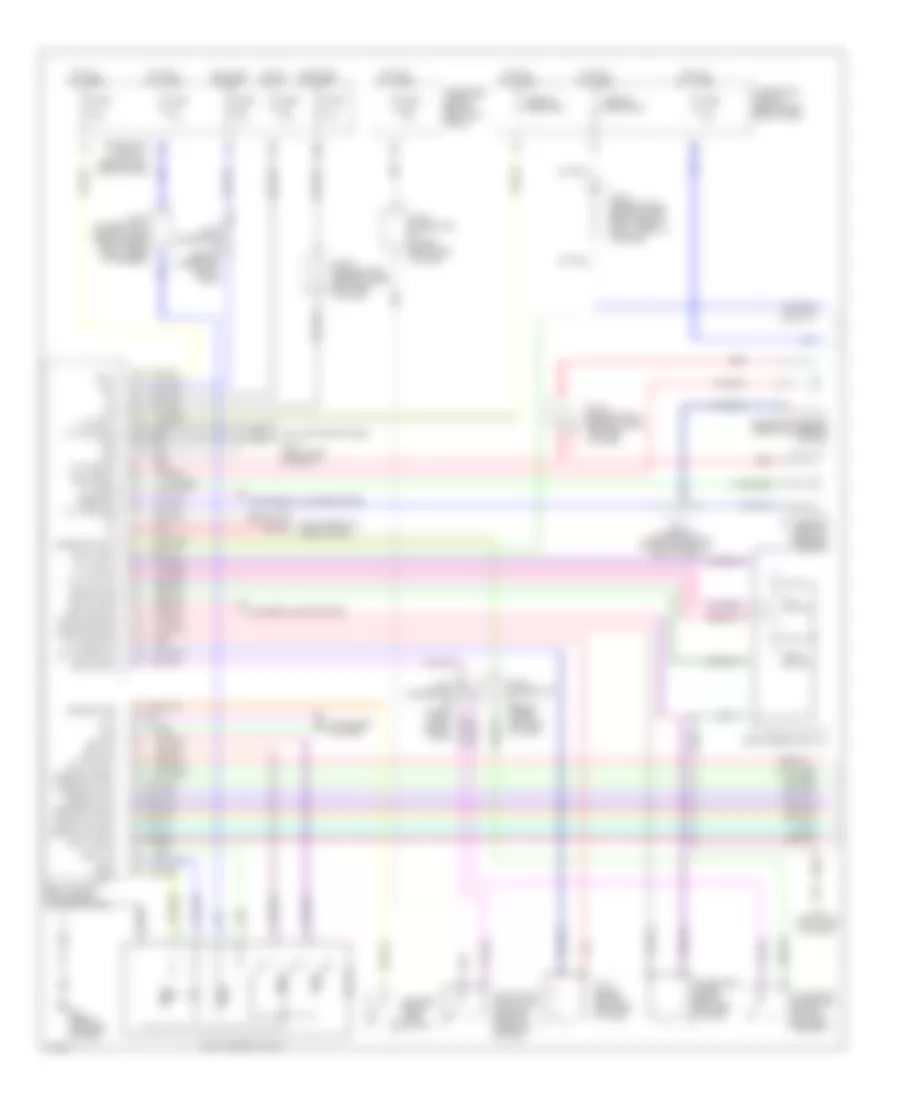
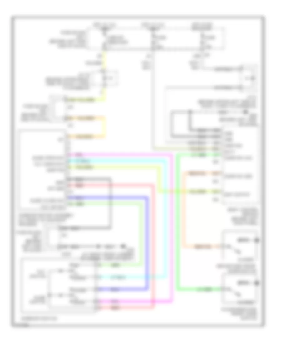
Gauges, Indicators & Clock Wiring Diagram for Infiniti M45 2003
List of elements for Gauges, Indicators & Clock Wiring Diagram for Infiniti M45 2003:
- (behind lower left side of dash) joint connector 25
- (green)
- (left front corner of engine compt)
- (left side of dash)
- (w/ odo, trip meter & a/t indicator)
- +12v
- 10k
- 15a
- A/t check
- A/t device
- Abs
- Air bag
- Anti-lock brakes system
- Auto
- Auto anti- dazzling inside mirror compass
- B17 (left front door sill)
- Bat
- Batt
- Belt
- Brake
- Brake fluid level switch (on brake fluid reservoir)
- Charge
- Clock
- Combination meter
- Computer data line system
- Cruise
- Cruise control system
- Door
- Door locks system
- E62
- E62 (left front corner of engine compt)
- Electronic power steering system
- Engine control module (ecm) (behind glove box)
- Fuel
- Fuel gauge
- Fuel level sensor unit (in fuel tank)
- Fuse 1 10a
- Fuse 21 10a
- Fuse 6 10a
- Fuse 8 10a
- Fuse 9 10a
- Fuse block (j/b) no. 1 (behind left end of dash)
- Gnd
- High beam
- Hot at all times
- Hot in acc or on
- Hot in on or start
- Illum
- Ind out
- Instrument cluster system (w/ vehicle information system)
- Interior lights system
- Joint connector 10 (upper left end of dash)
- Joint connector 11 (upper right side of dash)
- Joint connector 15 (behind upper right side of dash)
- Joint connector 3 side of dash) of dash)
- Led
- Left turn
- Light (+)
- Light (-)
- Low tire pressure warning control unit (behind center of dash)
- M114 (right side of dash)
- M24
- M41
- M42
- Malfunction indicator lamp
- Manual
- Mode select switch
- Nca
- Oil
- Oil pressure switch (front center of engine)
- Parking brake switch (on park brake assembly)
- Pnk
- Position select switch
- Red
- Right turn
- Seat belt buckle switch
- Set
- Slip
- Speedometer
- Starting/ charging system
- Tachometer
- Tire pressure
- Unified meter control unit
- Vdc off
- W/ auto drive positioner
- W/o auto drive positioner
- Washer
- Washer level switch (washer fluid reservoir)
- Water temp gauge
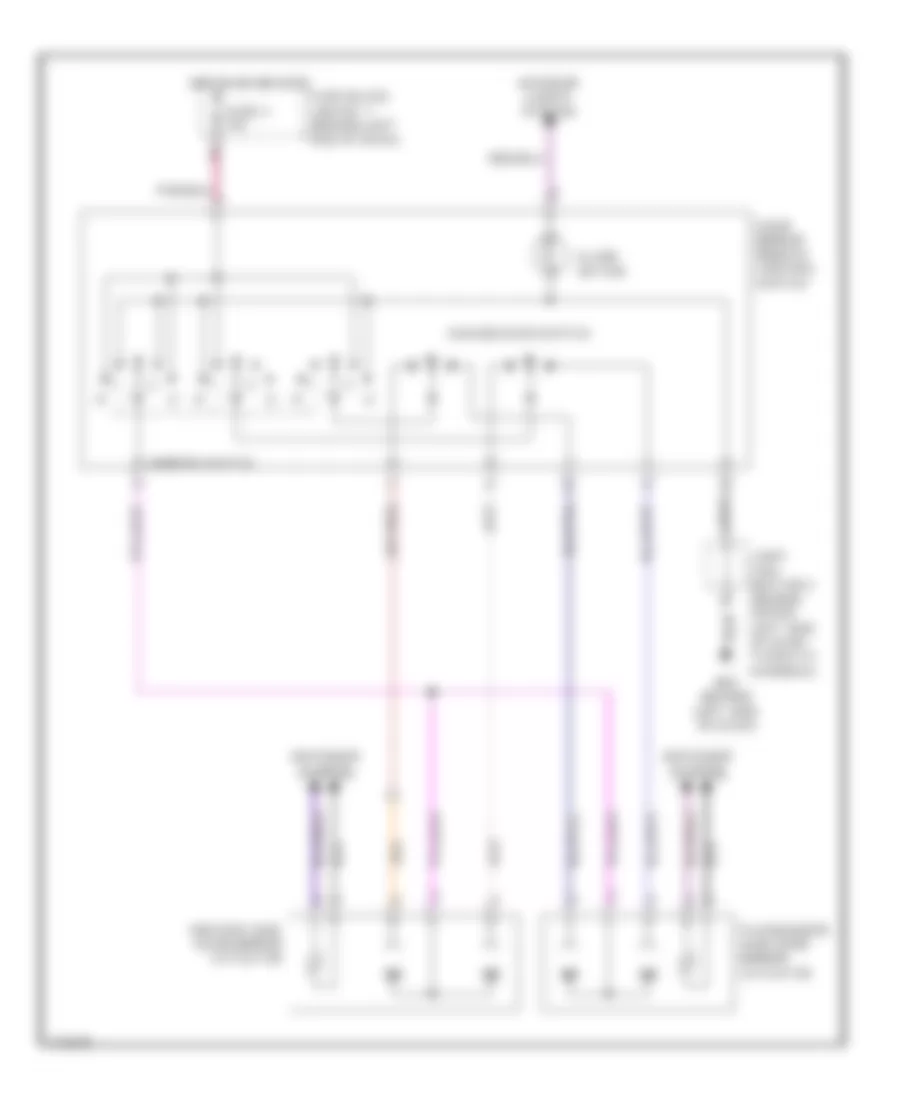
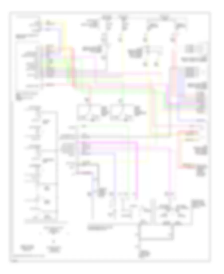
Vehicle Information System Wiring Diagram, with Navigation (1 of 2) for Infiniti M45 2003
List of elements for Vehicle Information System Wiring Diagram, with Navigation (1 of 2) for Infiniti M45 2003:
- 23r e3
- Ac-av
- Acc
- Acclk
- Air conditioning system
- Av & navi control unit (at front center of luggage compt)
- Av-ac
- Av-cn
- Av-me
- B29
- B30
- B57 (at center rear of trunk)
- Bat
- Body control module (behind left kick panel)
- Bus (+)
- Bus (-)
- Bus shield
- Cn-av
- Combination meter
- Combination switch (spiral cable)
- Computer data lines system
- Data out
- Display
- Fuse 1 10a
- Fuse 15a
- Fuse 21 10a
- Fuse block (j/b) no. 1 (behind left end of dash)
- Fuse, fusible link & relay block (j/b) (at right side of engine compt)
- Gnd
- Hot at all times
- Hot in acc or on
- Hot in on or start
- Ign
- Iiurx
- Iiutx
- Ill
- Ill con
- Interior lights system
- Joint connector 10 (behind upper left end of dash)
- Joint connector 3 (behind upper left end of dash)
- Joint connector 7 (behind upper left side of dash, taped to harness)
- Joint connector 9 (behind lower left side of dash)
- Low tire pressure warning control unit (behind center of dash)
- M1 19b
- M114 (behind right side of dash)
- M41
- M42
- M441
- M53
- Me-av
- Multifunction switch
- Nca
- Pnk
- Red
- Rgb gnd
- Rgb sync
- Rx strg
- Shield
- Sound systems
- Speed
- Steering switch
- Unified meter control unit
Vehicle Information System Wiring Diagram, with Navigation (2 of 2) for Infiniti M45 2003
List of elements for Vehicle Information System Wiring Diagram, with Navigation (2 of 2) for Infiniti M45 2003:
- (+)
- (-)
- Acc
- Acp a
- Acp b
- Audio out (+)
- Audio out (-)
- Audio phn (+)
- Audio phn (-)
- Audio shield
- Audio unit
- B234
- B256 (at right front corner of trunk)
- B57 (at center rear of trunk)
- B69
- B71
- Batt
- Bose speaker amplifier (at center front of trunk)
- Bus (+)
- Bus (-)
- Gnd
- M86
- M87
- Mic in (+)
- Mic in (-)
- Microphone
- Mute
- Mute pse in
- Nca
- Option connector 1 for voice activated system
- Option connector 2 for voice activated system
- Phn out (+)
- Phn out (-)
- Phn shield
- Phone (+)
- Phone (-)
- Pnk
- R10
- Red
- Shield
- Voice activated control module (left rear of luggage compt)
Vehicle Information System Wiring Diagram, without Navigation (1 of 2) for Infiniti M45 2003
List of elements for Vehicle Information System Wiring Diagram, without Navigation (1 of 2) for Infiniti M45 2003:
- (behind upper left side of dash) joint connector 5
- 23r e3
- Ac-av
- Acc
- Acclk
- Air conditioning system
- Av control unit (behind center of dash)
- Av-ac
- Av-cn
- Av-me
- B57 (at center rear of trunk)
- Bat
- Body control module (behind left kick panel)
- Bus (+)
- Bus (-)
- Bus shield
- Cn-av
- Combination meter
- Combination switch (spiral cable)
- Computer data lines system
- Data out
- Display
- Fuse 1 10a
- Fuse 15a
- Fuse 21 10a
- Fuse block (j/b) no. 1 (behind left end of dash)
- Fuse, fusible link & relay block (j/b) (at right side of engine compt)
- Gnd
- Hot at all times
- Hot in acc or on
- Hot in on or start
- Ign
- Iiurx
- Iiutx
- Ill
- Interior lights system
- Joint connector 10 (behind upper left end of dash)
- Joint connector 3 (behind upper left end of dash)
- Joint connector 7 (behind upper left side of dash, taped to harness)
- Joint connector 9 (behind lower left side of dash)
- Low tire pressure warning control unit (behind center of dash)
- M1 19b
- M114 (behind right side of dash)
- M41
- M42
- M441
- M50
- M53
- M77
- M78
- Me-av
- Multifunction switch
- Nca
- Pnk
- Red
- Rgb gnd
- Rgb sync
- Rx strg
- Shield
- Sound systems
- Speed
- Steering switch
- Unified meter control unit
Vehicle Information System Wiring Diagram, without Navigation (2 of 2) for Infiniti M45 2003
List of elements for Vehicle Information System Wiring Diagram, without Navigation (2 of 2) for Infiniti M45 2003:
- (+)
- (-)
- Acc
- Acp a
- Acp b
- Audio out (+)
- Audio out (-)
- Audio phn (+)
- Audio phn (-)
- Audio shield
- Audio unit
- B234
- B256 (at right front corner of trunk)
- B57 (at center rear of trunk)
- B69
- B71
- Batt
- Bose speaker amplifier (at center front of trunk)
- Bus (+)
- Bus (-)
- Gnd
- M86
- M87
- Mic in (+)
- Mic in (-)
- Microphone
- Mute
- Mute pse in
- Nca
- Option connector 1 for voice activated system
- Option connector 2 for voice activated system
- Phn out (+)
- Phn out (-)
- Phn shield
- Phone (+)
- Phone (-)
- Pnk
- R10
- Red
- Shield
- Voice activated control module (left rear of luggage compt)
INTERIOR LIGHTS
Courtesy Lamps Wiring Diagram (1 of 2) for Infiniti M45 2003
List of elements for Courtesy Lamps Wiring Diagram (1 of 2) for Infiniti M45 2003:
- (right front corner of engine compt)
- 10k
- 20b
- Acc
- All off
- Auto
- Bat
- Body control module (bcm) (behind left kick panel)
- Computer data lines system
- Data line a3
- Door sw (as)
- Door sw (dr)
- Door sw (rl)
- Door sw (rr)
- Driver front door switch
- E42
- Full
- Fuse 1 10a
- Fuse 32 10a
- Fuse 8 10a
- Fuse block (j/b) no. 1 (behind left end of dash)
- Fuse block (j/b) no. 2 (behind right kick panel)
- Gnd
- Half
- Hot at all times
- Hot in on or start
- Ign
- Ign key ill
- Ignition key hole illumination
- Iiurx
- Iutx
- Joint connector 15 (upper right side of dash)
- Joint connector 20 (upper right side of dash, taped to harness)
- Joint connector 5 (upper left side of dash, taped to harness)
- Key sw
- Key switch & key lock solenoid (key switch)
- M24 (left side of dash)
- Map/l (lh)
- Map/l (rh)
- Navigation system
- Personal lamp (rl)
- Personal lamp (rr)
- Personal lamp sw
- Pnk
- Rear interior lamp
- Right front door switch
- Total ill
Courtesy Lamps Wiring Diagram (2 of 2) for Infiniti M45 2003
List of elements for Courtesy Lamps Wiring Diagram (2 of 2) for Infiniti M45 2003:
- Auto
- B17 (at left front door sill)
- B217 (at right front door sill)
- Bat (c/b)
- Circuit breaker
- Closed
- D38
- D58
- D78
- Data line a3
- Driver door control unit
- Driver front door lcok actuator (door unlock sensor)
- Drivers step lamp
- E62 (left front corner of engine compt)
- Front interior lamp
- Fuse 21 10a
- Fuse 3 10a
- Fuse block (j/b) no. 1 (left end of dash)
- Gnd
- Hot at all times
- Hot in acc or on
- Interior lights illumination
- Joint connector (upper left end of dash, taped to harness)
- Joint connector (uppper left side of dash, taped to harness)
- Joint connector (uppper right side of dash, taped to harness)
- Junction connector 15 (upper right side of dash)
- Left map light
- Left rear door control unit
- Left rear door lock assembly (door switch)
- Left rear step lamp
- Local data line
- Locked
- M114 (right side of dash)
- M24 (left side of dash)
- Off
- Open
- Passenger door control unit
- Red
- Right front step lamp
- Right map light
- Right rear door control unit
- Right rear door lock assembly (door switch)
- Right rear step lamp
- Step/l
- Unlock sens
- Unlocked
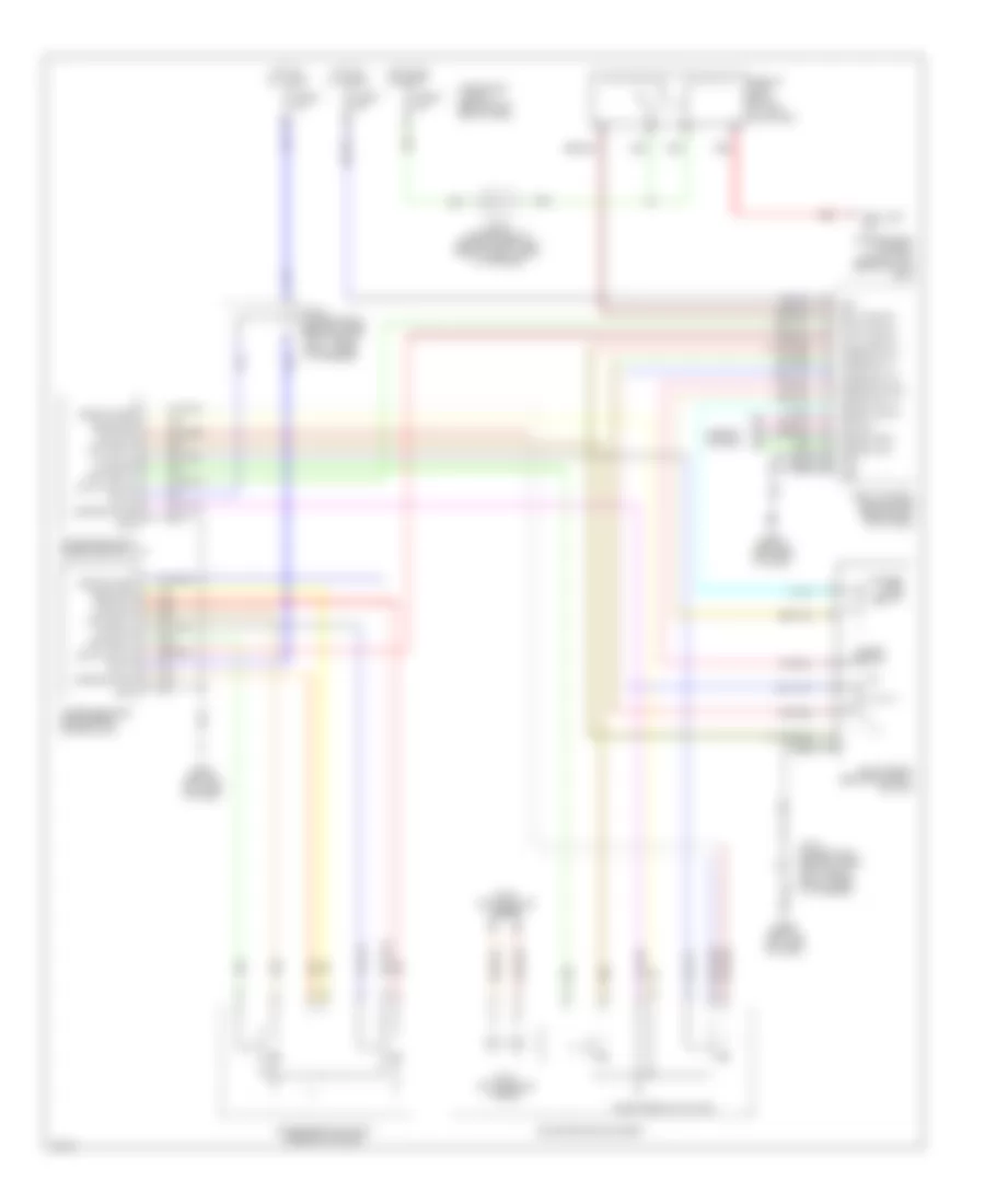
Instrument Illumination Wiring Diagram (1 of 2) for Infiniti M45 2003
List of elements for Instrument Illumination Wiring Diagram (1 of 2) for Infiniti M45 2003:
- 10k
- 12r
- 1st
- 20b
- 26r
- 2nd
- Auto
- Av & navi control unit (w/ navi) (at front center of luggage compt)
- Av control unit (w/o navi) (behind center of dash)
- B57 (at center rear of trunk)
- Bat
- Body control module (bcm) (left kick panel)
- Comb sw (auto)
- Combination meter
- Combination switch (light switch)
- Diode (behind upper left side of dash)
- Door sw (as)
- Door sw (dr)
- Driver front door switch
- Front interior lamp
- Fuse 1 10a
- Fuse 15a
- Fuse 6 10a
- Fuse 8 10a
- Fuse 9 10a
- Fuse block (j/b) no. 1 (behind left end of dash)
- Fuse, fusible link & relay block (j/b) (at right side of engine compt)
- Gnd1
- Gnd2
- Ground
- Headlamp battery saver control unit (behind left side of dash)
- Hot at all times
- Hot in on or start
- Ign sw
- Illumination
- Joint connector (behind upper left end of dash)
- Joint connector 11 (behind upper right side of dash)
- Joint connector 16 (behind upper right side of dash)
- Joint connector 21 (behind uppper left side of dash)
- Joint connector 5 (behind upper left side of dash)
- Light sw (1st)
- M114 (right side of dash)
- M115 (right side of dash)
- M24 (left side of dash)
- M25 (behind left side of dash)
- M25 (left side of dash)
- M33
- M34
- Nca
- Off
- Rap input
- Rap output
- Right front door switch
- T/l rly out 1
- T/l rly out 2
- T/l sw 1
- T/l sw 2
- Taillight relay
- Tal/l rly
- Unified meter control unit
Instrument Illumination Wiring Diagram (2 of 2) for Infiniti M45 2003
List of elements for Instrument Illumination Wiring Diagram (2 of 2) for Infiniti M45 2003:
- (right side of dash) m114
- (right side of dash) m115
- A/t device
- Ashtray
- Audio unit
- B17 (at left front door sill)
- B217 (at right front door sill)
- Climate controlled seat level switch
- Climate controlled seat switch
- Clock
- Driver side front power seat
- Front cigarette lighter
- Glove box lamp
- Hazard switch
- Headlamp aiming switch
- Illumination control switch
- Joint connector 1 (behind upper left end of dash)
- Joint connector 13 (behind upper right side of dash)
- Joint connector 2 (behind upper left end of dash)
- L1a
- L2a
- Left rear ashtray
- Lighter socket
- M25 (behind left side of dash)
- Multifunction switch
- Nca
- Passenger side front power seat
- Red
- Right rear ashtray
- Vdc off switch
- W/ navigation
- W/o navigation
Vanity Mirror & Trunk Lamp Wiring Diagram for Infiniti M45 2003
List of elements for Vanity Mirror & Trunk Lamp Wiring Diagram for Infiniti M45 2003:
- 10k
- B256 (at right front corner of trunk)
- Driver side vanity mirror lamp
- E62 (at left front corner of engine compartment)
- Fuse 8 10a
- Fuse block (j/b) no. 1 (behind left end of dash)
- Hot at all times
- Joint connector 15 (upper right side of dash)
- Passenger side vanity mirror lamp
- Pnk
- Trunk room lamp
- Trunk room lamp switch
MEMORY SYSTEMS
Memory Systems Wiring Diagram (1 of 3) for Infiniti M45 2003
List of elements for Memory Systems Wiring Diagram (1 of 3) for Infiniti M45 2003:
- (left end of dash)
- 20b
- A/t device detention switch (shifter assembly)
- Acc
- Adp steering switch
- Batt
- Body control module (bcm) (left kick panel)
- Circuit breaker 1
- Circuit breaker 2
- Computer data lines system
- Data line 3
- Data line a1
- Data line a2
- Detent switch
- Door sw (dr)
- Drivers front door switch
- Exterior lamps system
- Fuse 10a
- Fuse block (j/b) no. 1 (behind left end of dash)
- Fuse block (j/b) no. 2 (behind right kick panel)
- Gnd
- Hot at all times
- Hot in on or accy
- Hot in on or start
- Hot in start
- Ign
- Instrument cluster
- Instrument cluster system
- Iurx
- Iutx
- Joint connector
- Joint connector (behind upper left end of dash)
- Joint connector (upper right side of dash)
- Joint connector 15 (behind upper right side of dash, taped to harness)
- Joint connector 2 (behind upper left end of dash)
- Joint connector 5 (behind upper left side of dash)
- Key switch
- Key switch & key lock solenoid (right of steering column)
- M114 (right side of dash)
- M115 (right side of dash)
- M24
- M24 (behind left side of dash)
- Mem 1
- Mem 1 sw
- Mem 2
- Mem 2 sw
- Mirror sw down
- Mirror sw left
- Mirror sw right
- Mirror sw up
- Pnk
- Red
- Rev lamp sw
- Seat memory switch
- Select sw left
- Select sw right
- Set sw
- Speed sig
- Tele motor (fr)
- Tele motor (rr)
- Tele signal
- Tele sw (fr)
- Tele sw (rr)
- Tele switch
- Telescope motor (behind left side of dash)
- Telescopic sensor (right of steering column)
- Tilt batt
- Tilt motor (behind left side of dash)
- Tilt motor dwn
- Tilt motor up
- Tilt sens
- Tilt sensor (right of steering column)
- Tilt sw dwn
- Tilt sw up
- Tilt switch
- Tilt tele gnd
- Tilt/tele 5v
Memory Systems Wiring Diagram (2 of 3) for Infiniti M45 2003
List of elements for Memory Systems Wiring Diagram (2 of 3) for Infiniti M45 2003:
- Bat
- Data line a2
- Data line a3
- Door mirror remote control switch
- Down
- Driver side door mirror actuator
- Drivers side door mirror control unit
- Gnd
- Joint connector 15 (upper right side of dash, taped to harness)
- Joint connector 5 (upper left side of dash, taped to harness)
- Left
- M114 (right side of dash)
- M24 (left side of dash)
- M25 (left side of dash)
- Mirror motor
- Mirror sens (left/right)
- Mirror sens (up/down)
- Motor (left/right)
- Motor (up/down)
- Passenger side door mirror actuator
- Passengers side door mirror control unit
- Red
- Right
- Sensor (left/right)
- Sensor gnd
- Sensor power
- Sensor pwr
Memory Systems Wiring Diagram (3 of 3) for Infiniti M45 2003
List of elements for Memory Systems Wiring Diagram (3 of 3) for Infiniti M45 2003:
- 14a
- 15b
- 16a
- 32a
- 32b
- 32c
- B148
- B149
- B17 (left front door sill)
- Batt
- Data line a1
- Driver's seat control unit (under driver's seat)
- Driver's side lifting device (bottom of seat frame)
- Driver's side power seat switch
- Driver's side reclining motor
- Driver's side sliding motor
- Front lifting sensor
- Frt lift dwn
- Frt lift up
- Frt pulse sw
- Frt reclin mtr
- Frt reclin sw
- Frt slide mtr
- Frt slide sw
- Gnd
- Lumbar support motor
- Pnk
- Pulse sw gnd
- Rear lifting sensor
- Reclin puls sw
- Recline switch
- Red
- Rr lft up
- Rr lift dwn
- Rr lift up
- Rr pulse sw
- Rr reclin mtr
- Rr reclin sw
- Rr slide mtr
- Rr slide sw
- Sig gnd
- Slide pulse sw
- Slide switch
- Switch frt lift
- Switch lumbar
- Switch rear lift
NAVIGATION
Navigation Wiring Diagram, Base (1 of 2) for Infiniti M45 2003
List of elements for Navigation Wiring Diagram, Base (1 of 2) for Infiniti M45 2003:
- (behind upper left of dash) j/c 3
- (center rear of trunk) b57
- 19b
- 23r
- Ac-av
- Acc
- Acclk
- Auto a/c system
- Av and navi control unit (at center rear of luggage compartment)
- Av-ac
- Av-cn
- Av-me
- B188
- B29
- B30
- Bat
- Bose speaker amp (at center front of luggage compt)
- Bus shield
- Bus+
- Bus-
- Ch1+ out
- Ch1- out
- Cn-av
- Display
- Fuse 10a
- Fuse 15a
- Fuse block (j/b) no.1 (behind left end of dash)
- Fuse, fusible link & relay block (j/b) (at right side of engine comp)
- Gnd
- Gps ant gnd
- Gps antenna
- Gps sig
- Hot at all times
- Hot in acc or on
- Hot in on or start
- Ign
- Ill
- Ill con
- Interior lights system
- J/c 10 (behind upper left side of dash)
- J/c 9 (behind lower left of dash)
- Left front door speaker
- M114 (right side of dash)
- Me-av
- Multi-function switch
- Navi +
- Navi -
- Nca
- Pnk
- Red
- Rgb gnd
- Rgb sync
- Shield
- Speed
- Voice +
- Voice -
Navigation Wiring Diagram, Base (2 of 2) for Infiniti M45 2003
List of elements for Navigation Wiring Diagram, Base (2 of 2) for Infiniti M45 2003:
- Backup lamp relay (at left kick panel)
- Body control module (behind left kick panel)
- Combination meter
- Data line computer system
- Data link connector (under left side of dash)
- Iiurx
- Iiutx
- J/c 7 (behind upper left of dash)
- J/c 8 (behind lower left of dash)
- Nca
- Pnk
- Red
- Rev lamp rly
- Transmission control module (behind glove box)
- Unified meter control unit
Navigation Wiring Diagram, High Level (1 of 2) for Infiniti M45 2003
List of elements for Navigation Wiring Diagram, High Level (1 of 2) for Infiniti M45 2003:
- (behind upper left of dash) j/c 3
- (center rear of trunk) b57
- 19b
- 23r
- Ac-av
- Acc
- Acclk
- Auto a/c system
- Av and navi control unit (at center rear of luggage compartment)
- Av-ac
- Av-cn
- Av-me
- B188
- B29
- B30
- B69
- B71
- Bat
- Bus shield
- Bus+
- Bus-
- Cn-av
- Display
- Fuse 10a
- Fuse 15a
- Fuse block (j/b) no.1 (behind left end of dash)
- Fuse, fusible link & relay block (j/b) (at right side of engine comp)
- Gnd
- Gps ant gnd
- Gps antenna
- Gps sig
- Hot at all times
- Hot in acc or on
- Hot in on or start
- Ign
- Ill
- Ill con
- Interior lights system
- J/c 10 (behind upper left side of dash)
- J/c 9 (behind lower left of dash)
- M114 (right side of dash)
- Me-av
- Nca
- Pnk
- Red
- Rgb gnd
- Rgb sync
- Shield
- Speed
- Voice +
- Voice -
- Voice activated cntrl mod (at left rear of luggage compt)
- Warning system
Navigation Wiring Diagram, High Level (2 of 2) for Infiniti M45 2003
List of elements for Navigation Wiring Diagram, High Level (2 of 2) for Infiniti M45 2003:
- Acc
- Audio unit
- B256 (at right front corner of trunk)
- Back-up
- Backup lamp relay (at left kick panel)
- Body control module (behind left kick panel)
- Bose speaker amplifier (at center front of luggage compt)
- Bus+
- Bus-
- Case gnd
- Cd auto changer
- Ch1+ out
- Ch1- out
- Chg req
- Combination meter
- Data gnd
- Data link connector (under left side of dash)
- Fuse 20a
- Fuse, fusible link & relay block (j/b) (at right side of engine comp)
- Gnd
- Hot at all times
- Iiurx
- Iiutx
- J/c 7 (behind upper left of dash)
- J/c 8 (behind lower left of dash)
- Left front door speaker
- M114 (right side of dash)
- Multi-function switch
- Navi +
- Navi -
- Nca
- Pnk
- Red
- Req comb
- Rev lamp rly
- Rx (chg)
- Rxd comb
- Shield
- Shield gnd
- System data lines computer
- Transmission control module (behind glove box)
- Tx (chg)
- Txd comb
- Unified meter control unit
- Warning system
POWER DISTRIBUTION
Power Distribution Wiring Diagram (1 of 3) for Infiniti M45 2003
List of elements for Power Distribution Wiring Diagram (1 of 3) for Infiniti M45 2003:
- (at right side of engine compartment, in engine room box) fuse, fusible link & relay box
- 16r
- 20r
- 22r
- 23r
- 27r
- 28r
- 29r
- 33r
- 34r
- Air conditioner relay
- Air conditioning system
- Anti-lock brakes system
- Av & navi control unit, display, voice activated control module, sound system & navigation system, option connector-2 (for voice activated system), audio unit & cd auto changer
- Battery
- Blower relay
- Coil
- Contact
- Cruise control systyem
- E24 (at right side of engine compartment)
- Ecm relay
- Engine controls system
- Engine controls system, computer data lines system & transmissions system
- Engine controls system, transmissions system, shifty interlock system, door locks system, anti-theft system, power windows system, key switch & key lock solenoid (key switch)
- From fuse 13, 15a (diagram 2 of 3)
- From fuse 21, 10a (diagram 2 of 3)
- From ignition switch (diagram 2 of 3)
- Fuel pump relay
- Fuse 10a
- Fuse 15a
- Fuse 20a
- Fuse block (j/b) 2 (behind right kick panel)
- Fuse, fusible link & relay block (j/b) (at right side of engine compartment, in engine room box)
- Fuse, fusible link & relay box (at right side of engine compartment, in engine room box)
- Fusible link b 50a
- Fusible link c 50a
- Fusible link f 30a
- Fusible link g 50a
- Fusible link h 40a
- Fusible link k 50a
- Fusible link l 50a
- Headlamp relay 1
- Headlamp relay-2
- Headlights system
- Horn relay
- Ignition relay
- Nca
- Phone (handset)
- Pnk
- Red
- Seats system
- Security horn relay
- Sound system
- Starting/ charging system
- Tail lamp relay
- Throttle control motor relay
- To fuse block (j/b) no.1 (diagram 2 of 3)
- To fuse block (j/b) no.1 (diagram 3 of 3)
- To ignition switch (diagram 2 of 3)
- Transmissions system
- Wiper/ washer system
Power Distribution Wiring Diagram (2 of 3) for Infiniti M45 2003
List of elements for Power Distribution Wiring Diagram (2 of 3) for Infiniti M45 2003:
- (at right front corner of engine compartment) e42
- (behind left end of dash) fuse block (j/b) no.1
- (behind left side of dash) m24
- (behind upper right side of dash, taped to harness) j/c 15
- (diagram 1 of 3)
- 10a
- 10c
- 19b
- 20b
- Acc
- Accessory relay
- Air conditioning system
- Anti-lock brakes system & electronic power steering system
- Body computer system & memory systems
- Circuit breaker
- Combination flasher unit
- Defogger system, seats system & electronic mufflers system
- Door locks system, anti-theft system, power windows system, defogger system, power tops system, memory systems, seats system, headlights system, exterior lights system, interior lights system, warning systems, wiper/washer system & body computer module (bcm)
- Engine controls system
- Engine controls system, headlights system
- From fusible link c (diagram 1 of 3)
- From fusible link g c
- From ignition relay (diagram 1 of 3)
- Front cigarette lighter socket
- Front power socket
- Fuse 10a
- Fuse 15a
- Fuse block (in fuse, fusible link & relay box (j/b))
- Fuse block (j/b) no.1 (behind left end of dash)
- Headlights system
- Homelink universal transceiver, compass & power mirrors system
- Ign
- Ignition switch
- Instrument cluster system, transmission system, mirrors system, starting/charging system, headlights system, exterior lights system, navigation system & cruise control system
- J/c 19 (behind upper right side of dash, taped to harness)
- Low tire pressure warning control unit, door locks system, anti-theft system, memory systems, headlights system, interior lights system, sound system, power antenna system, combination meter, navigation system, voice activated control module & body computer system
- Low tire pressure warning control unit, navigation system & cruise control system
- Off
- Pnk
- Power mirrors system, defogger system & handset (option)
- Red
- Shift interlock system & cruise control system
- Start
- Starting/ charging system
- To blower relay (diagram 1 of 3)
- To fuel pump relay (diagram 1 of 3)
- To fuse block (j/b) no. 1 (diagram 3 0f 3)
- To ignition relay (diagram 1 of 3)
Power Distribution Wiring Diagram (3 of 3) for Infiniti M45 2003
List of elements for Power Distribution Wiring Diagram (3 of 3) for Infiniti M45 2003:
- (diagram 2 of 3)
- 10k
- 11b
- Body control module (bcm)
- Circuit breaker
- Coil
- Combination flasher unit
- Combination meter, data link connector, transmissions system, shift interlock system, low tire pressure warning control unit, anti-theft system, air conditioning system, headlights system, headlamp battery saver control unit, warning systems, clock & handset (option)
- Defogger system
- Door locks system, anti-theft system, power windows system, interior lights system & body computer system
- Door locks system, anti-theft system, power windows system, power tops system, interior lights system & body computer system
- From accessory relay k
- From fusible link h, 40a (diagram 1 of 3)
- Fuse 10a
- Fuse 15a
- Fuse 20a
- Fuse block (j/b) no.1 (behind left end of dash)
- Homelink universal transceiver, interior lights system & compass
- Interior lights system
- Power mirrors system, memory systems & interior lights system
- Seats system, body control module (bcm) & driver seat control unit (lcu02)
- Shift interlock system, stoplamp switch, anti-lock brakes system, exterior lights system & cruise control system
- Trunk lid opener relay
- Trunk, tailgate & fuel door release system
POWER DOOR LOCKS
Door Lock Wiring Diagram for Infiniti M45 2003
List of elements for Door Lock Wiring Diagram for Infiniti M45 2003:
- (at left front door sill) b17
- (at right front door sill) b217
- (behind left side of dash) m24
- (behind upper right side of dash, taped to harness) j/c 15
- 20b
- Bat
- Bat (c/b)
- Between full stroke & n
- Body control module (behind left kick panel)
- Circuit breaker
- Dash) m24
- Data line a3
- Door lock
- Door lock & unlock switch
- Door sw (as)
- Door sw (dr)
- Door sw (rl)
- Door sw (rr)
- Door unlock
- Driver door control unit (lcu01)
- Driver side front door key cylinder switch
- Driver side front door lock actuator
- Driver side front door switch
- Full stroke
- Fuse 10a
- Fuse block j/b 1 (behind left end of dash)
- Fuse block j/b 2 (behind right kick panel)
- Gnd
- Hot at all times
- Hot in on or start
- Ign
- J/c 11 (behind upper right side of dash, taped to harness)
- J/c 16 (behind upper right side of dash, taped to harness)
- J/c 20 (behind upper right side of dash, taped to harness)
- J/c 21 (behind upper left side of dash, taped to harness)
- J/c 5 (behind upper left side of dash, taped to harness)
- Key sw
- Key switch & key lock solenoid (key switch)
- Left rear door control unit
- Left rear door lock actuator
- Left rear door lock assembly (door switch)
- Local data line
- Lock
- Lock sw
- Locked
- M145
- M24 (behind left side of dash)
- Passenger door control unit
- Passenger side front door lock actuator
- Passenger side front door switch
- Right rear door control unit
- Right rear door lock actuator
- Right rear door lock assembly (door switch)
- Unlock
- Unlock sens
- Unlock sw
- Unlocked
Remote/Keyless Entry Wiring Diagram (1 of 2) for Infiniti M45 2003
List of elements for Remote/Keyless Entry Wiring Diagram (1 of 2) for Infiniti M45 2003:
- (at left front door sill) b17
- (at right front door sill) b217
- (behind left side of dash) m24
- 10d
- 20d
- Acc
- Anti-theft system
- Bat (c/b)
- Battery
- Body control module (behind left kick panel)
- Circuit breaker
- Closed
- Data line a-3
- Data line a3
- Data out
- Door lock
- Door sw (as)
- Door sw (dr)
- Door sw (rl)
- Door sw (rr)
- Door unlock
- Driver door control unit (lcu01)
- Driver side front door lock actuator
- Driver side front door switch
- E201
- E204
- E42 (at right front corner of engine compartment)
- Flasher
- Fuse 10a
- Fuse block j/b 1 (behind left end of dash)
- Fuse block j/b 2 (behind right kick panel)
- Ground
- Horn chirp
- Hot at all times
- Hot in acc or on
- Iiurx
- Iiutx
- J/c 10 (behind upper left end of dash, taped to harness)
- J/c 16 (behind upper right side of dash, taped to harness)
- J/c 20 (behind upper right side of dash, taped to harness)
- J/c 21 (behind upper left side of dash, taped to harness)
- K/less gnd
- K/less power (5v)
- K/less signal
- Key sw
- Key switch & key lock solenoid (key switch)
- Left rear door lock assembly (door switch)
- Local data line
- Locked
- M145
- M24 (behind left side of dash)
- Off
- Open
- Passenger side front door switch
- Pnk
- Power
- Remote keyless entry receiver
- Right rear door lock assembly (door switch)
- Trunk lid opener actuator
- Trunk lid opener cancel switch
- Trunk lid opener relay
- Trunk opener
- Unlock sens
- Unlocked
Remote/Keyless Entry Wiring Diagram (2 of 2) for Infiniti M45 2003
List of elements for Remote/Keyless Entry Wiring Diagram (2 of 2) for Infiniti M45 2003:
- (at left front door sill) b17
- (at right front door sill) b217
- (behind left side of dash) m24
- Av & navi control unit (or av control unit)
- Av-me
- B17 (at left front door sill)
- B217 (at right front door sill)
- Bat (c/b)
- Combination flasher unit
- Connector used w/av & navi control unit
- Data link connector (partial) (under left side of dash)
- Door lock
- Door unlock
- Exterior lights system
- Gnd
- Ground
- H/w sw & bcm
- J/c 11 (behind upper right side of dash, taped to harness)
- J/c 15 (behind upper right side of dash, taped to harness)
- J/c 20 (behind upper right side of dash, taped to harness)
- J/c 7 (behind upper left side of dash, taped to harness)
- J/c 8 (behind lower left side of dash, taped to harness)
- Left rear door control unit
- Left rear door lock actuator
- Lh t/s lamp
- Local data line
- Locked
- Me-av
- Nca
- Passenger door control unit
- Passenger side front door lock actuator
- Pnk
- Rh t/s lamp
- Right rear door control unit
- Right rear door lock actuator
- Shield
- Un-locked
- Unlock sens
- Unlocked
- W/av & navi control unit
- W/av control unit
POWER MIRRORS
Auto Anti-dazzling Inside Mirror Wiring Diagram for Infiniti M45 2003
List of elements for Auto Anti-dazzling Inside Mirror Wiring Diagram for Infiniti M45 2003:
- +12v
- Auto anti- dazzling inside mirror
- Driver side door mirror (auto anti-dazzling mirror)
- E42 (at right front corner of engine compartment)
- Fuse 1 10a
- Fuse block (j/b) no. 1 (behind left end of dash)
- Gnd
- Hot in on or start
- Oec (+)
- Oec (-)
- Oec feed
- Oec return
Power Mirrors Wiring Diagram for Infiniti M45 2003
List of elements for Power Mirrors Wiring Diagram for Infiniti M45 2003:
- Changeover switch
- Defogger system
- Door mirror remote control switch
- Driver's side door mirror actuator
- Fuse 4 10a
- Fuse block (j/b) no. 1 (behind left end of dash)
- Hot in on or accy
- Illumi- nation
- Interior lights system
- Joint con- nector 5 (behind upper left side of dash, taped to harness)
- M25 (behind left side of dash)
- Mirror switch
- Passenger's side door mirror actuator
Reverse Interlock Wiring Diagram for Infiniti M45 2003
List of elements for Reverse Interlock Wiring Diagram for Infiniti M45 2003:
- Auto anti-dazzling mirror
- Back-up lamp relay (at left kick panel)
- Bat
- Batt
- Body control module (bcm) (behind left kick panel)
- Change- over switch
- Data line a-2
- Data line a-3
- Door mirror actuator
- Door mirror remote control switch
- Driver side door mirror
- Driver side door mirror control unit
- Fuse 3 10a
- Fuse 8 10a
- Fuse 9 10a
- Fuse block (j/b) no. 1 (behind left end of dash)
- Gnd
- Hot at all times
- Hot in on or start
- Joint connector 10 (behind upper left end of dash, taped to harness)
- Joint connector 15 (behind upper right side of dash, taped to harness)
- Joint connector 5 (behind upper left side of dash, taped to harness)
- Left/right
- M24 (behind left side of dash)
- M25 (behind left side of dash)
- Memory sw1
- Memory sw2
- Memory system
- Mirror motor
- Mirror sw dwn
- Mirror sw lt
- Mirror sw rt
- Mirror sw up
- Mirror switch
- Oec (+)
- Oec (-)
- Passenger side door mirror actuator
- Passenger side door mirror control unit
- Red
- Rev-lamp sw
- Select sw lt
- Select sw rt
- Sens gnd
- Sens power
- Set sw
- Transmission control module (tcm) (behind glove box)
- Up/down
POWER SEATS
Climate Control Seats Wiring Diagram (1 of 2) for Infiniti M45 2003
List of elements for Climate Control Seats Wiring Diagram (1 of 2) for Infiniti M45 2003:
- (left front door sill) b17
- (right front door sill) b217
- 12v logic pwr
- 20b
- Back sen ret
- Back sen sig
- Back ted 2
- Blower (-)
- Blower ctrl
- Blower elec
- Blower tach
- Climate controlled seat blower motor
- Climate controlled seat control unit
- Climate controlled seat relay (right side of engine compt)
- Climate controlled seat switch
- Climate controlled seat temperature dial
- Cool
- Cool ind
- Cool on ind
- Cool sw
- Cush sen ret
- Cush sen sig
- Cush ted 1
- Cush ted 2
- Driver side front power seat
- E42 (right front corner of engine compt)
- Fuse 71 15a
- Fuse 72 15a
- Fuse block (j/b) no. 1 (behind left end of dash)
- Fuse i 10a
- Fuse, fusible link link & relay box (at right siee of engine compt, in engine room box)
- Gnd
- Heat
- Heat ind
- Heat on ind
- Heat sw
- Hot at all times
- Hot in on or start
- Ign run
- Illum
- Interior lights system
- J10
- J11
- J12
- J13
- J14
- J15
- J16
- J17
- J18
- J19
- J20
- J5 j5
- Jca
- Joint connector 5 (behind upper left side of dash, taped to harness)
- L1a
- L2a
- Pwr gnd
- Pwr in
- Red
- Rpm ctrl
- Seat back thermal electric device
- Seat cushion thermal electric device
- Sensor
- Tach out
- Ted-fin assembly
- Temp ctrl pwr
- Temp ctrl sig
Climate Control Seats Wiring Diagram (2 of 2) for Infiniti M45 2003
List of elements for Climate Control Seats Wiring Diagram (2 of 2) for Infiniti M45 2003:
- (right front door sill) b217
- 12v logic pwr
- Back sen ret
- Back sen sig
- Back ted 2
- Blower (-)
- Blower ctrl
- Blower elec
- Blower tach
- Climate controlled seat blower motor
- Climate controlled seat control unit
- Climate controlled seat switch
- Climate controlled seat temperature dial
- Cool
- Cool ind
- Cool on ind
- Cool sw
- Cush sen ret
- Cush sen sig
- Cush ted 1
- Cush ted 2
- Gnd
- Heat
- Heat ind
- Heat on ind
- Heat sw
- Ign run
- Illum
- Interior lights system
- J10
- J11
- J12
- J13
- J14
- J15
- J16
- J17
- J18
- J19
- J20
- J5 j5
- Jca
- L1a
- L2a
- Passenger side front power seat
- Pwr gnd
- Pwr in
- Red
- Rpm ctrl
- Seat back thermal electric device
- Seat cushion thermal electric device
- Sensor
- Tach out
- Ted-fin assembly
- Temp ctrl pwr
- Temp ctrl sig
Power Seats Wiring Diagram for Infiniti M45 2003
List of elements for Power Seats Wiring Diagram for Infiniti M45 2003:
- B17 (at left front door sill)
- B217 (at right front door sill)
- Circuit breaker 2
- Driver side front power seat
- Fuse block (j/b) no. 1 (behind left end of dash)
- Hot at all times
- Joint connector 15 (behind upper right side of dash, taped to harness)
- Lifting
- Lifting motor (front)
- Lifting motor (rear)
- Lifting switch (front)
- Lumbar support motor
- Lumbar support switch
- Passenger side front power seat
- Pnk
- Power seat switch
- Reclining
- Reclining motor
- Red
- Sliding motor
- Sliding switch
- Switch
- Switch (rear)
POWER TOP/SUNROOF
Power Top/Sunroof Wiring Diagram for Infiniti M45 2003
List of elements for Power Top/Sunroof Wiring Diagram for Infiniti M45 2003:
- 16b
- Batt
- Body control module (behind left kick panel)
- Circuit breaker
- Close
- Closed
- Door sw (as)
- Door sw (dr)
- Driver side front door switch
- E201
- E42 (at right front corner of engine compartment)
- Fuse 10a
- Fuse block j/b 1 (behind left end end of dash)
- Fuse block j/b 1 (behind left end of dash)
- Gnd
- Hot at all times
- Hot in on or start
- Ignition
- J/c 16 (behind upper right side of dash, taped to harness)
- J/c 5 (behind upper left side of dash, taped to harness)
- M1 20b
- M24 (behind left side of dash)
- N down
- N open
- Open
- Passenger side front door switch
- Rap output
- Red
- Slide close sw
- Slide open sw
- Slide switch
- Sunroof motor assembly (at front of sun roof opening)
- Sunroof switch
- Sw gnd
- Tilt down sw
- Tilt switch
- Tilt up sw
POWER WINDOWS
Power Windows Wiring Diagram (1 of 2) for Infiniti M45 2003
List of elements for Power Windows Wiring Diagram (1 of 2) for Infiniti M45 2003:
- (behind left side of dash) m24
- (behind right side of dash) m114
- 20b
- Auto down
- Auto up
- Bat
- Bat (c/b)
- Between full stroke & n
- Body control module (bcm) (behind left kick panel)
- Circuit breaker
- Closed
- Data line a-3
- Data link connector (partial) (under left side of dash)
- Data out
- Door lock & unlock switch illumination
- Door sw (as)
- Door sw (dr)
- Down
- Driver door control unit (lcu01)
- Driver side
- Driver side front door key cylinder switch
- Driver side front power window regulator
- Encoder
- Encoder pwr
- Front door switch (driver side)
- Front door switch (passenger side)
- Front power window main switch
- Full closed
- Full stroke
- Fuse 10a
- Fuse block (j/b) 1 (behind left end of dash)
- Gnd
- Hot at all times
- Hot in on or start
- Ign
- Iiurx
- Iiutx
- J/c 15 (behind upper right side of dash, taped to harness)
- J/c 16 (behind upper right side of dash, taped to harness)
- J/c 21 (behind upper left side of dash, taped to harness)
- J/c 5 (behind upper left side of dash, taped to harness)
- J/c 8 (behind lower left side of dash, taped to harness)
- K/less gnd
- K/less power (5v)
- K/less signal
- Key switch
- Left rear
- Limit switch
- Local data line
- Lock
- Lock switch
- Open
- Other
- Passenger side
- Pnk
- Power
- Power window switch illumination
- Pulse
- Remote keyless entry receiver
- Right rear
- Un-lock
- Unlock switch
Power Windows Wiring Diagram (2 of 2) for Infiniti M45 2003
List of elements for Power Windows Wiring Diagram (2 of 2) for Infiniti M45 2003:
- (at left front door sill) b17
- (at right front door sill) b217
- (behind left side of dash) m24
- Auto down
- Auto up
- Av & navi control unit (or av control unit)
- Av-me
- Bat (c/b)
- Connector used w/av & navi control unit
- Door lock & unlock switch illumination
- Down
- Encoder
- Encoder pwr
- Front power window regulator (passenger side)
- Front power window sub- switch
- Front power window sub-switch
- Full closed
- Fuse 10a
- Fuse block j/b 2 (behind right kick panel)
- Gnd
- Hot at all times
- Inserted
- J/c 20 (behind upper right side of dash, taped to harness)
- J/c 7 (behind upper left side of dash, taped to harness)
- Key switch & key lock solenoid (key switch)
- Left rear door control unit
- Left rear power window regulator
- Left rear power window sub-switch
- Limit switch
- Local data line
- M145
- Me-av
- Nca
- Other
- Passenger door control unit
- Power window switch illumination
- Pulse
- Right rear door control unit
- Right rear power window regulator
- Right rear power window sub-switch
- Shield
- W/av & navi control unit
- W/av control unit
- With- drawn
RADIO
Radio Wiring Diagram (1 of 2) for Infiniti M45 2003
List of elements for Radio Wiring Diagram (1 of 2) for Infiniti M45 2003:
- ant signal illum ctrl
- audio out shld
- chg lh in (-)
- chg req rx chg -h/u
- vnc mic (-)
- 23r
- Acc
- Antenna amp
- Antenna amplifier
- Audio out lh- audio out lh+ audio out rh(-)
- Audio out rh(+)
- Audio unit
- Back-up
- Bus (+) shield
- Bus (-)
- Cd auto changer (right rear corner of luggage compt)
- Cd comb req
- Cd comb rxd
- Cd comb txd
- Chg lh in (+) chg rh in (-) chg rh in (+) chg gnd
- Data gnd
- Fuse 21 10a
- Fuse 52 15a
- Fuse block (j/b) no.1 (behind left side of dash)
- Fuse, fusible
- Gnd (case)
- Hot at all times
- Hot in on or acc
- Interior lights
- J/c 10 (behind upper left end of dash)
- Lh (+) out
- Lh (-) out
- Light switch
- Link & relay box (right front side of engine compt)
- M114 (right side of dash)
- M86
- M87
- M88
- Nca
- Pnk
- Red
- Rh (+) out
- Rh (-) out
- Shield bus (-) bus (+)
- Shield gnd
- Tx h/u -chg
- Vnc mic (+) vnc mic shield
- Window ant
- Window antenna (main)
- Window antenna (sub)
Radio Wiring Diagram (2 of 2) for Infiniti M45 2003
List of elements for Radio Wiring Diagram (2 of 2) for Infiniti M45 2003:
- Acc
- B231
- B232
- B233
- B234
- B256 (right front of trunk)
- Bat
- Bose speaker amplifier (center front of luggage compartment)
- Bus (+)
- Bus (-)
- Bus +
- Bus -
- Bus shield
- Ch1+ output
- Ch1- output
- Ch2+ output
- Ch2- output
- Ch3+ output
- Ch3- output
- Ch4+ output
- Ch4- output
- Ch5+ output
- Ch5- output
- Ch7+ output
- Ch7- output
- Ch8+ output
- Ch8- output
- Combination switch (spiral cable)
- Data
- Display
- Fuse, fusible link and relay block (j/b) (right front side of engine compartment)
- Fusible link j 30a
- Gnd
- Ground
- Horn system
- Hot at all times
- Left front door speaker
- Left instrument speaker
- Left rear door speaker
- Mic +
- Mic -
- Multifunction switch
- Nca
- Radio in lh (+)
- Radio in lh (-)
- Radio in rh (+)
- Radio in rh (-)
- Rd strg
- Red
- Right front door speaker
- Right instrument speaker
- Right rear door speaker
- Shield
- Steering switch
- Woofer
SHIFT INTERLOCK
Shift Interlock Wiring Diagram for Infiniti M45 2003
List of elements for Shift Interlock Wiring Diagram for Infiniti M45 2003:
- (behind left side of dash) m24
- (behind left side of dash) m25
- A/t device
- Bat (+)
- Body control module (behind left kick panel)
- Detection switch (key)
- Detent sw (key)
- Fuse 10a
- Fuse 15a
- Fuse block (j/b) 1 (behind left end of dash)
- Fuse block j/b 2 (behind right kick panel)
- Gnd
- Hot at all times
- Hot in on or start
- Ign sw
- Inserted
- J/c 11 (behind upper right side of dash)
- J/c 2 (behind upper left end of dash)
- J/c 20 (behind upper right side of dash, taped to harness)
- J/c 3 (behind upper left end of dash)
- J/c 7 (behind upper left side of dash, taped to harness)
- Key lock sol
- Key lock solenoid
- Key switch & key lock solenoid
- M145
- Others
- Shift lock control unit (behind left side dash)
- Shift lock sol
- Shift lock solenoid
- Stop lamp switch (above brake pedal)
- Withdrawn
STARTING/CHARGING
Charging Wiring Diagram for Infiniti M45 2003
List of elements for Charging Wiring Diagram for Infiniti M45 2003:
- 20r
- Alternator
- Battery
- Charge warning indicator
- Combination meter
- E307 (at right front of engine compartment)
- Fuse 56 15a
- Fuse 9 10a
- Fuse block (j/b) no 1 (behind left end of dash)
- Fuse, fusible link & relay box (at right side of engine compartment, in engine room box)
- Hot at all times
- Hot in on or start
- Joint connector no 10 (behind upper left end of dash)
Starting Wiring Diagram for Infiniti M45 2003
List of elements for Starting Wiring Diagram for Infiniti M45 2003:
- 14r
- 15r
- 21r
- 24r
- 29r
- 31r
- Acc
- Battery
- Cruise control system
- E24 (at right side of engine compartment)
- Fuse link g 50a
- Fuse, fusible link & relay block (at right side of engine compartment)
- Fuse, fusible link & relay box (at right side of engine compartment, in engine room box)
- Hot at all times
- Ignition switch
- Nca
- Off
- Park/ neutral position relay
- Start
- Start rly
- Starter motor
- Transmission control module (behind glove box)
SUPPLEMENTAL RESTRAINTS
Supplemental Restraints Wiring Diagram (1 of 2) for Infiniti M45 2003
List of elements for Supplemental Restraints Wiring Diagram (1 of 2) for Infiniti M45 2003:
- (at left front door sill) b16
- (at right front door sill) b216
- (behind left side of dash) m24
- (behind right side of dash) m114
- Air bag
- Air bag diagnosis sensor unit (under rear of center console)
- Air bag w/l
- As1 +
- As1 -
- As2 +
- As2 -
- B13
- B213
- C-lh +
- C-lh -
- C-rh +
- C-rh -
- Combination meter
- Data link connector (partial) (under left side of dash)
- Dr1 +
- Dr1 - (dr2 -)
- Dr2 +
- Eczs +
- Eczs -
- Eczs gnd
- Fuse 10a
- Fuse block (j/b) 1 (behind left end of dash)
- Gnd
- Hot in on or start
- Ignition
- J/c 10 (behind upper left end of dash, taped to harness)
- J/c 11 (behind upper right side of dash, taped to harness)
- K-line
- Left front side air bag module
- Left lock input
- Left side air bag (satellite) sensor (at base of left "b" pillar)
- Left side curtain air bag module
- M103
- M41
- M42
- Nca
- P-lh +
- P-lh -
- P-rh +
- P-rh -
- Pnk
- Red
- Right front seat belt pre-tensioner
- Right front side air bag module
- Right lock input
- Right side air bag (satellite) sensor (at base of right "b" pillar)
- Right side curtain air bag module
- S-lh +
- S-lh -
- S-rh +
- S-rh -
- Sat lh +
- Sat lh -
- Sat rh +
- Sat rh -
- Seat belt
- Unified meter control unit
Supplemental Restraints Wiring Diagram (2 of 2) for Infiniti M45 2003
List of elements for Supplemental Restraints Wiring Diagram (2 of 2) for Infiniti M45 2003:
- (at left front door sill) b17
- (at left front of engine compartment) e69
- (at right front door sill) b217
- 14 (or 15a)
- Combination switch (spiral cable)
- Crash zone sensor (at center front of engine compartment)
- Driver air bag module
- Driver side front power seat
- Fastened
- Front passenger air bag module
- Left front seat belt pre- tensioner
- M445
- M446
- M54
- Nca
- Passenger side front power seat
- Seat belt buckle switch
- Unfastened
TRANSMISSION
A/T Wiring Diagram (1 of 2) for Infiniti M45 2003
List of elements for A/T Wiring Diagram (1 of 2) for Infiniti M45 2003:
- A/t fluid temperature sensor 1
- A/t fluid temperature sensor 2
- A/t unit assembly
- Atf1 gnd
- Atf2 gnd
- D/c-1
- D/c-2
- Data bit1
- Direct clutch solenoid
- F26
- F27
- F28
- Fr/b-1
- Front brake solenoid
- Gnd
- High & low reverse clutch solenoid
- Hlr/c-1
- I/c-1
- I/c-2
- Inh gnd
- Inh-sw3
- Input clutch solenoid
- Lc/b-1
- Lc/b-2
- Line pressure solenoid
- Low coast brake solenoid
- Mon
- Nca
- Park/ neutral position switch
- Pnk
- Pressure switch 1 (fr/b)
- Pressure switch 2 (lc/b)
- Pressure switch 3 (i/c)
- Pressure switch 5 (d/c)
- Pressure switch 6 (hlr/c)
- Psb2
- Psc2
- Red
- Revolution sensor
- Sel1
- Sel2
- Sel3
- Sel4
- Shift control unit
- Ss gnd
- Ss vin
- Sw gnd
- Sw3 out
- T1 out
- T2 out
- Torque converter clutch solenoid
- Turbine
- Turbine revolution sensor
- Vcc
- Vign out
- Vin
- Vout
A/T Wiring Diagram (2 of 2) for Infiniti M45 2003
List of elements for A/T Wiring Diagram (2 of 2) for Infiniti M45 2003:
- (behind right side of dash)
- (right front of engine compt) a/t pv ignition relay
- (with a/t indicator)
- A/t check ind
- A/t device
- Atf1
- Atf2
- Auto
- Back-up lamp relay (at left kick panel)
- Batt
- Can-h
- Can-l
- Combination meter
- Computer data lines system
- Connector (dlc) (under left side of dash)
- Data bit1
- Data link
- Dc sol
- Down
- E24 (right side of engine compt)
- Ecm relay
- Engine control module (behind glove box)
- Engine controls system
- Exterior lights system
- F8 (left front of engine)
- Fb sol
- Fuse 10a
- Fuse block (j/b) 1 (left end of dash)
- Fuse block (j/b) 2 (right kick panel)
- Gnd-c
- Gnd-p
- Hot at all times
- Hot in on or start
- Ic sol
- Illum
- Inh-sw1
- Inh-sw2
- Inh-sw3 atcu
- Inh-sw3 mon
- Inh-sw4
- Interior lights system
- J/c 10 (behind upper left side of dash)
- J/c 11 (behind upper right side of dash)
- J/c 19 (behind upper right side of dash)
- J/c 20 (behind upper right side of dash)
- J/c 5 (behind upper left side of dash)
- K-line
- Lcb sol
- M114
- M24 (behind left side of dash)
- M25 (behind left side of dash)
- Manual
- Mode select switch
- Nca
- Pl sol
- Pnk
- Position select switch
- Psb2
- Psc2
- Pvign
- Rc sol
- Red
- Rev rly
- Sel1
- Sel2
- Sel3
- Sel4
- Ssoff
- Start rly
- Starting/ charging system
- Tcc sol
- Transmission control module (behind glove box)
- Turbine 1
- Turbine 2
- Unified meter control unit
- Vign
- Vign out
- Vsp1
TRUNK, TAILGATE, FUEL DOOR
Trunk & Fuel Door Release Wiring Diagram for Infiniti M45 2003
List of elements for Trunk & Fuel Door Release Wiring Diagram for Infiniti M45 2003:
- 10d
- 20d
- Bat
- Body control module (bcm) (left kick panel)
- E42 (at right front corner of engine compt)
- Fuel lid opener actuator (right side of luggage compt)
- Fuel lid opener switch
- Fuse 15 10a
- Fuse 3 10a
- Fuse block (j/b) no. 1 (left end of dash)
- Gnd
- Hot at all times
- M24 (left side of dash)
- Trunk lid & fuel lid opener switch
- Trunk lid opener actuator (center rear of deck lid)
- Trunk lid opener cancel switch
- Trunk lid opener relay
- Trunk lid opener switch
- Trunk opener
- Trunk opener switch
WARNING SYSTEMS
Warning Systems Wiring Diagram for Infiniti M45 2003
List of elements for Warning Systems Wiring Diagram for Infiniti M45 2003:
- (right right side of dash) m115
- (w/ auto drive positioner)
- (w/o auto drive positioner)
- 12r
- 15a
- 1st
- 20b
- 26r
- 2nd
- Auto
- B17 (at left front door sill)
- Bat
- Body control module (bcm) (behind left kick panel)
- Chime
- Comb- ination switch (lighting switch)
- Door sw (dr)
- Driver's seat belt buckle switch (in front power seat)
- Front door switch (driver side)
- Fuse 1 10a
- Fuse 3 10a
- Fuse 32 10a
- Fuse 54 15a
- Fuse 6 10a
- Fuse block (j/b) no. 1 (behind left end of dash)
- Fuse block (j/b) no. 2 (behind right kick panel)
- Fuse, fusible link & relay block (j/b) (at right side of engine compt)
- Gnd
- Gnd1
- Gnd2
- Headlamp battery saver control unit (behind left side of dash)
- Hot at all times
- Hot in on or start
- Ign sw
- Ignition
- J/c 11 (behind upper right side of dash)
- J/c 13 (behind upper right side of dash)
- J/c 16 (behind upper right side of dash)
- J/c 20 (behind upper right side of dash)
- J/c 21 (behind upper left side of dash)
- J/c 5 (behind upper left side of dash)
- Key sw
- Key switch & key lock solenoid (key switch)
- Lt sw (1st)
- M24 (behind left side of dash)
- M25 (behind left side of dash)
- M33
- M34
- Nca
- Off
- Seat blt sw
- T/l rly out1
- T/l rly out2
- T/l sw1
- T/l sw2
- Tail lamp relay
- Warning chime (behind right side of dash)
WIPER/WASHER
Wiper/Washer Wiring Diagram for Infiniti M45 2003
List of elements for Wiper/Washer Wiring Diagram for Infiniti M45 2003:
- (at right side of engine compartment) e24
- (behind left side of dash) m24
- (behind left side of dash) m25
- 20b
- Battery
- Body control module (behind left kick panel)
- Combination meter
- Combination switch (front wiper switch)
- Computer data lines system
- Corner of engine compartment) e62
- E204
- E215
- Front washer motor (in washer fluid reservoir)
- Front wiper motor (on left side of firewall)
- Front wiper relay (in fuse, fusible link & relay block (j/b))
- Fuse 10a
- Fuse 20a
- Fuse block (j/b) 1 (behind left end of dash)
- Fuse block (j/b) 2 (behind right kick panel)
- Ground
- High
- Hot at all times
- Hot in on or start
- Ignition
- Int
- Int (vr)
- J/c 16 (behind upper right side of dash, taped to harness)
- J/c 25 (behind lower left side of dash, near pass through grommet)
- J/c 5 (behind upper left side of dash, taped to harness)
- J/c 9 (behind lower left side of dash, taped to harness)
- Low
- M41
- Mist
- Move
- Off
- Pnk
- Red
- Speed signal
- Stop
- Unified meter control unit
- Variable intermittent wiper volume
- Wash
- Wiper amp
- Wiper auto stop
- Wiper sw (wash)
- Wiper sw int