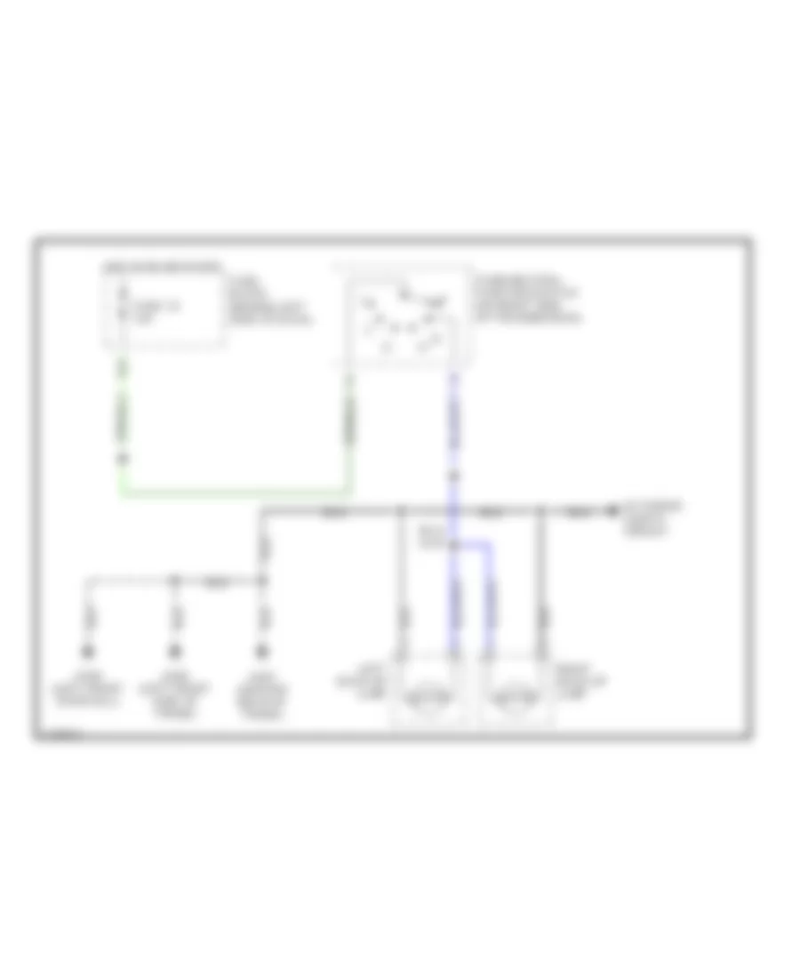
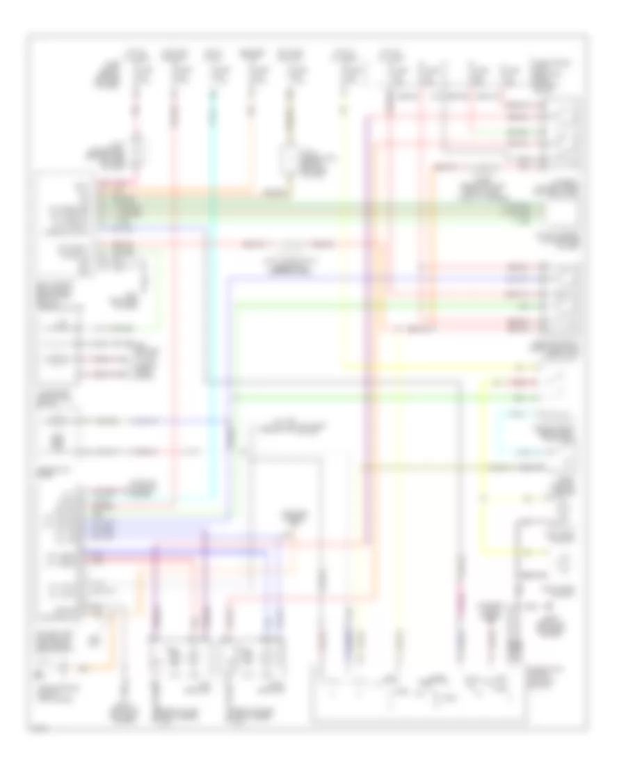
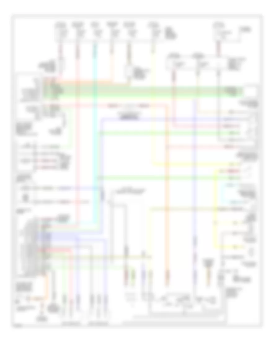
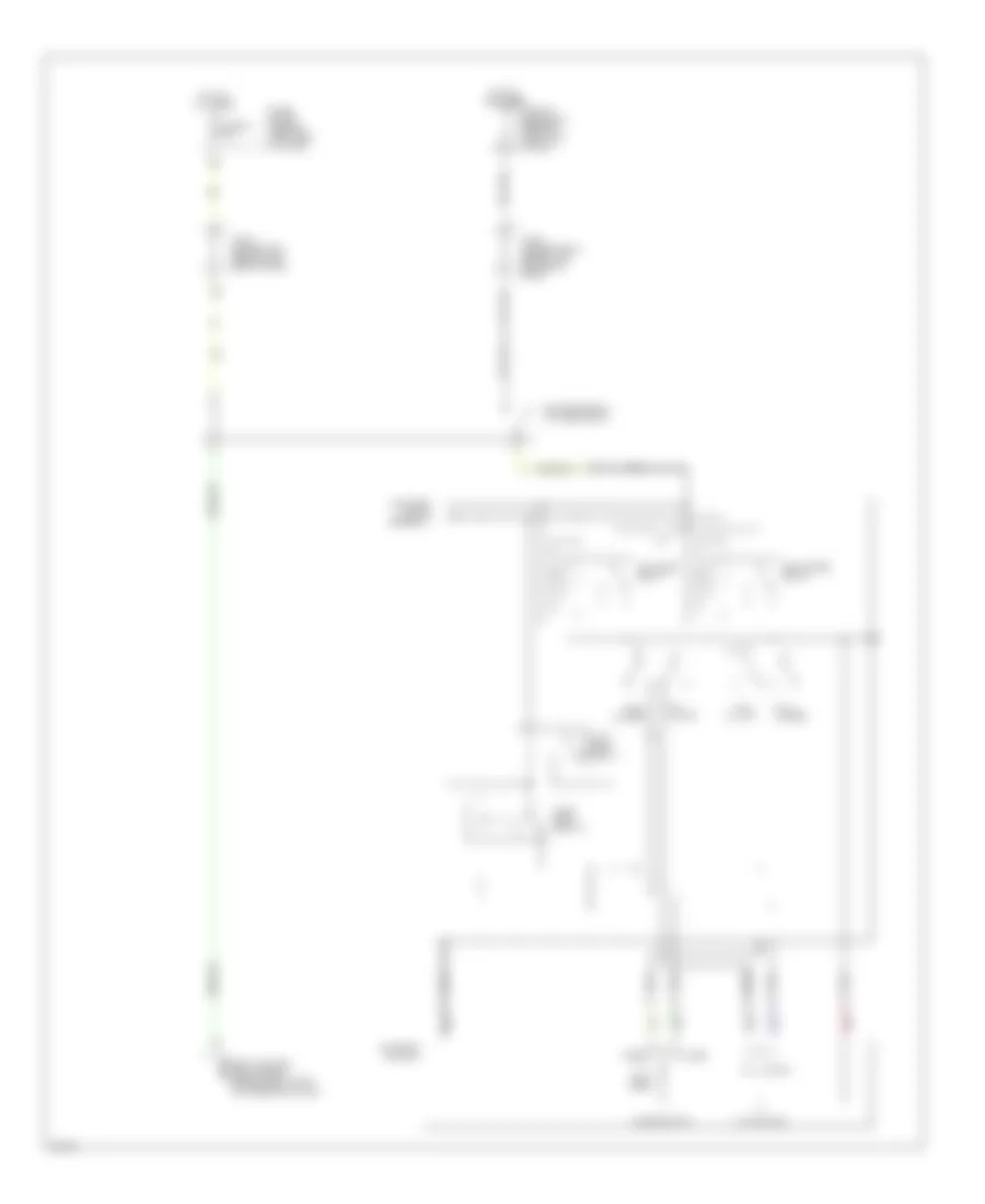
AIR CONDITIONING
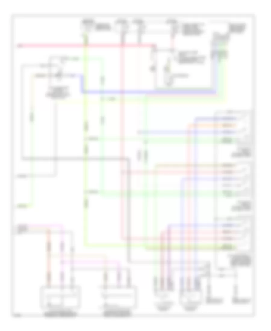
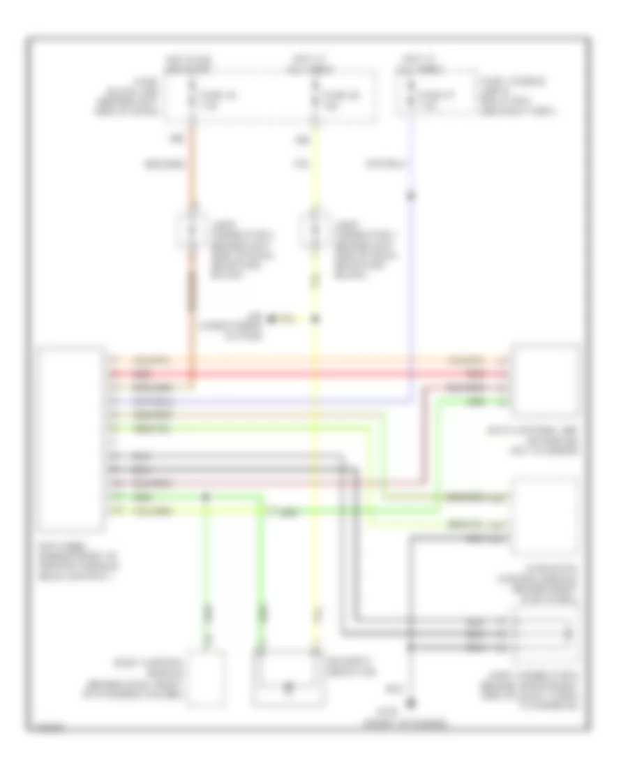
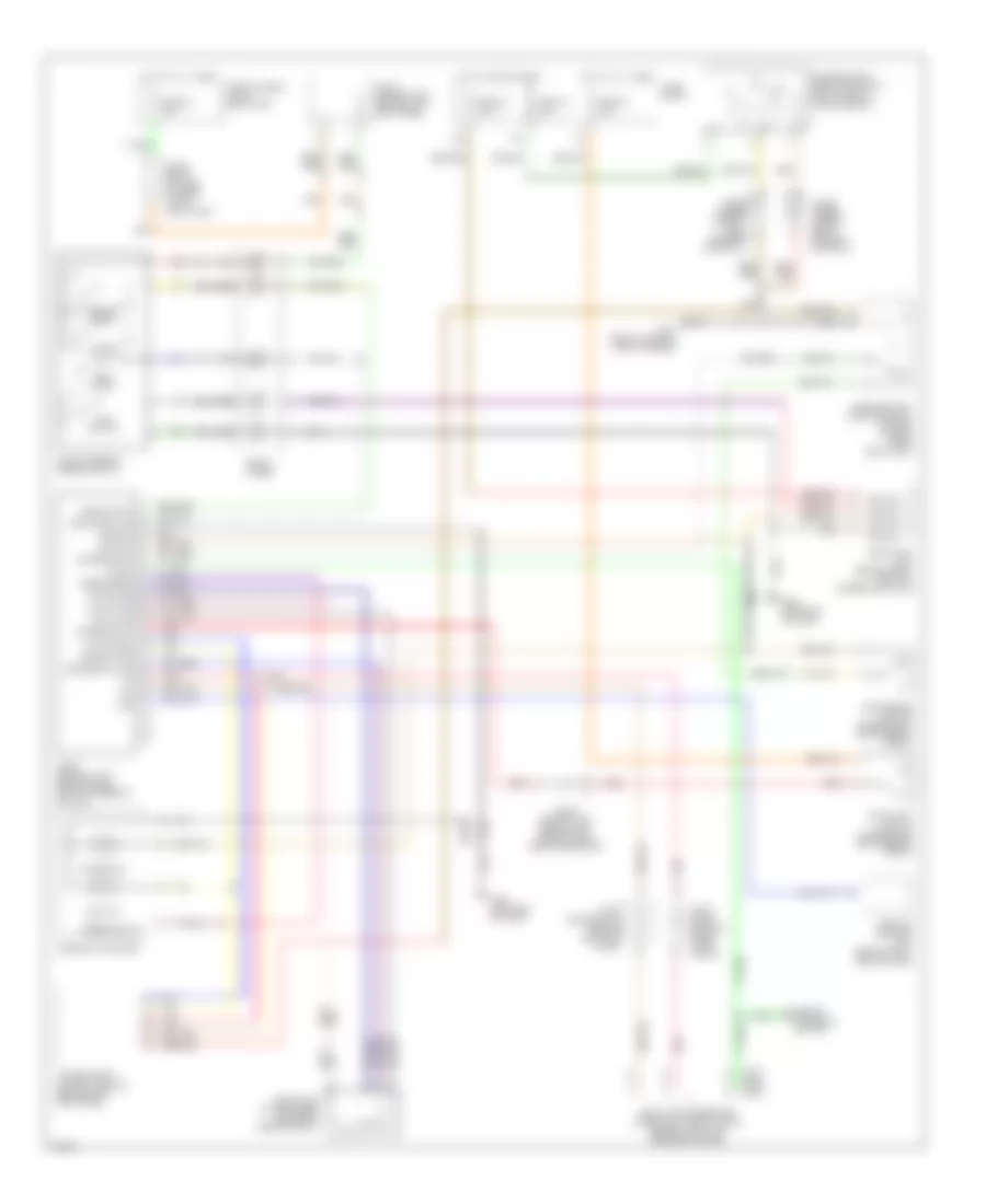
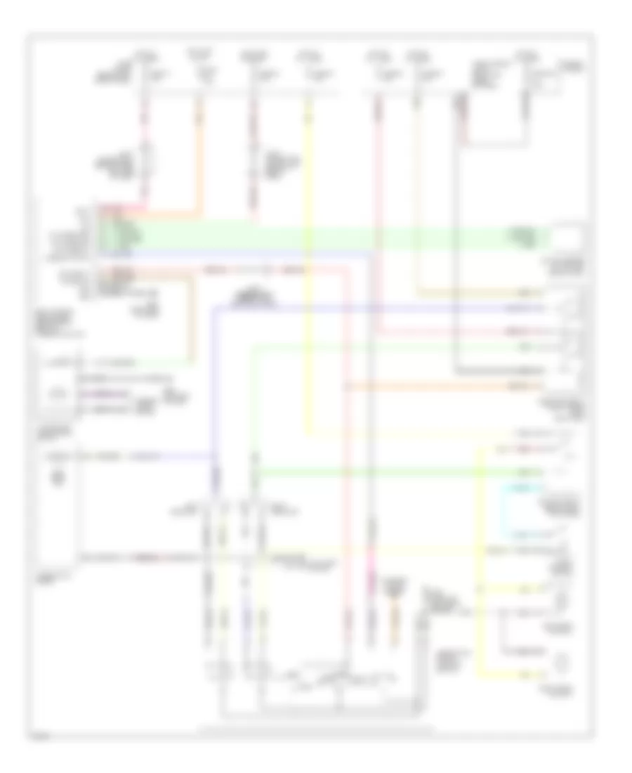
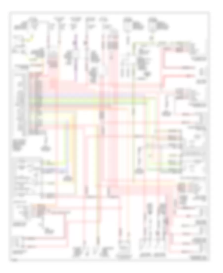
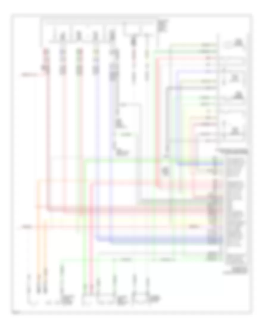
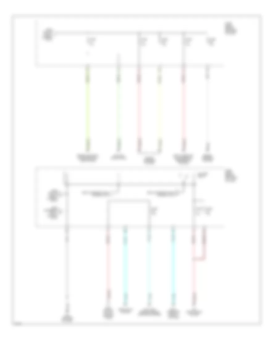
Automatic A/C Wiring Diagram (1 of 2) for Infiniti Q45 2000

List of elements for Automatic A/C Wiring Diagram (1 of 2) for Infiniti Q45 2000:
- 16b
- 20% fre
- 20% fre fre
- A/c auto amplifier (behind dash, on left side of center console)
- A/c control unit (center of dash)
- Acc
- Amb sens
- Ambient sensor (a/c) (front of eng compt, between cooling fans)
- Bat
- Blower motor
- Clk (fr)
- Close
- Combination meter
- Comp on comp on
- Defogger system
- Fan control amplifier (behind right side of dash)
- Fan f/b
- Fan gate
- Ficd
- Fre
- Fre(+) rec(-)
- Fre(-) rec(+)
- Fuse 10a
- Fuse 15a
- Fuse 7.5a
- Fuse block (behind left side of dash)
- G100 (left front of engine compt)
- G101 (right front of engine compt)
- G200 (left kick panel)
- G201 (right side of dash)
- Gnd
- Hot at all times
- Hot in acc or on
- Hot in on or start
- Ign
- Ill
- In-vehicle sensor (at right of steering column)
- Incar sens
- Intake door motor (under right side of dash, on intake unit)
- Intake sens
- Intake sensor (behind right side of dash)
- Interior lights system
- Joint connector 1 (near fuse block)
- Joint connector 11 (behind top center of dash, taped to harness)
- Joint connector 5 (behind upper right side of dash, taped to harness)
- Lan-sig
- Light
- Mode door motor (behind left side of center console, on heater unit)
- Open
- Open/close
- Pnk
- Rear vent door motor (behind left front side of center console)
- Rec
- Rec 20% fre
- Rec fre
- Red
- Rr def
- Rr/def f/b
- Rx (fr)
- Sck
- Sens gnd
- Speed sens
- Speed sig
- Sun sens
- Sunload sensor (on right defroster grille)
- Thermal transmitter (on top front center of engine)
- Tx (fr)
- Vactr
- W/t sens
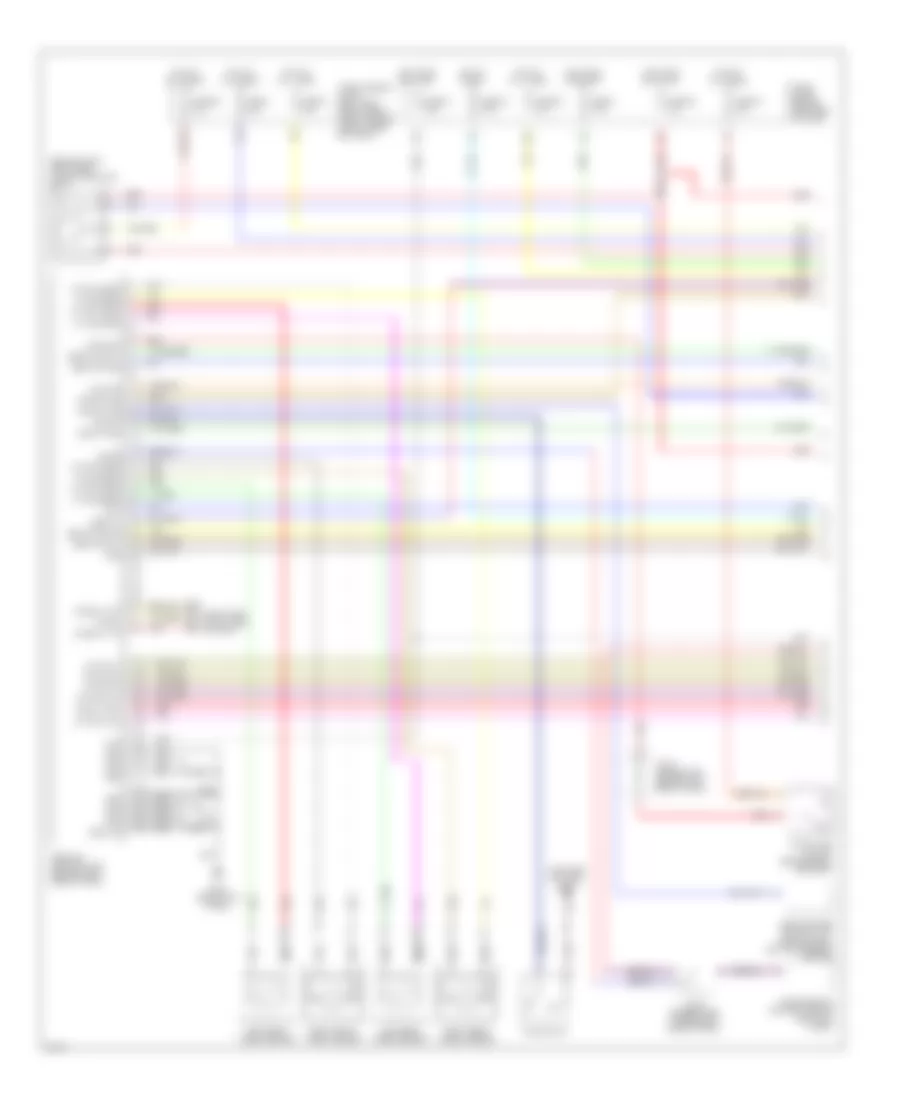
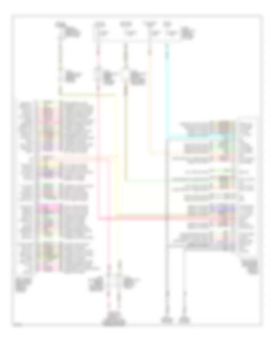
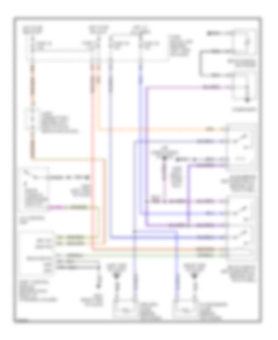
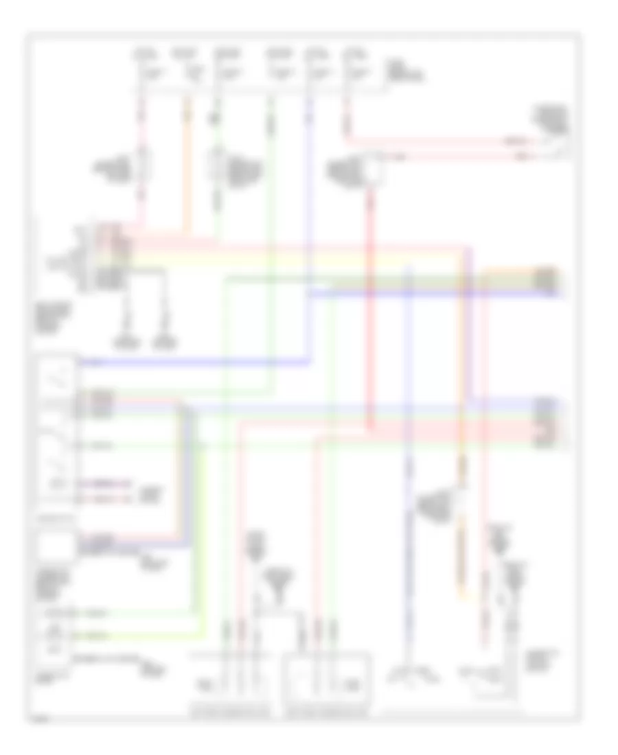
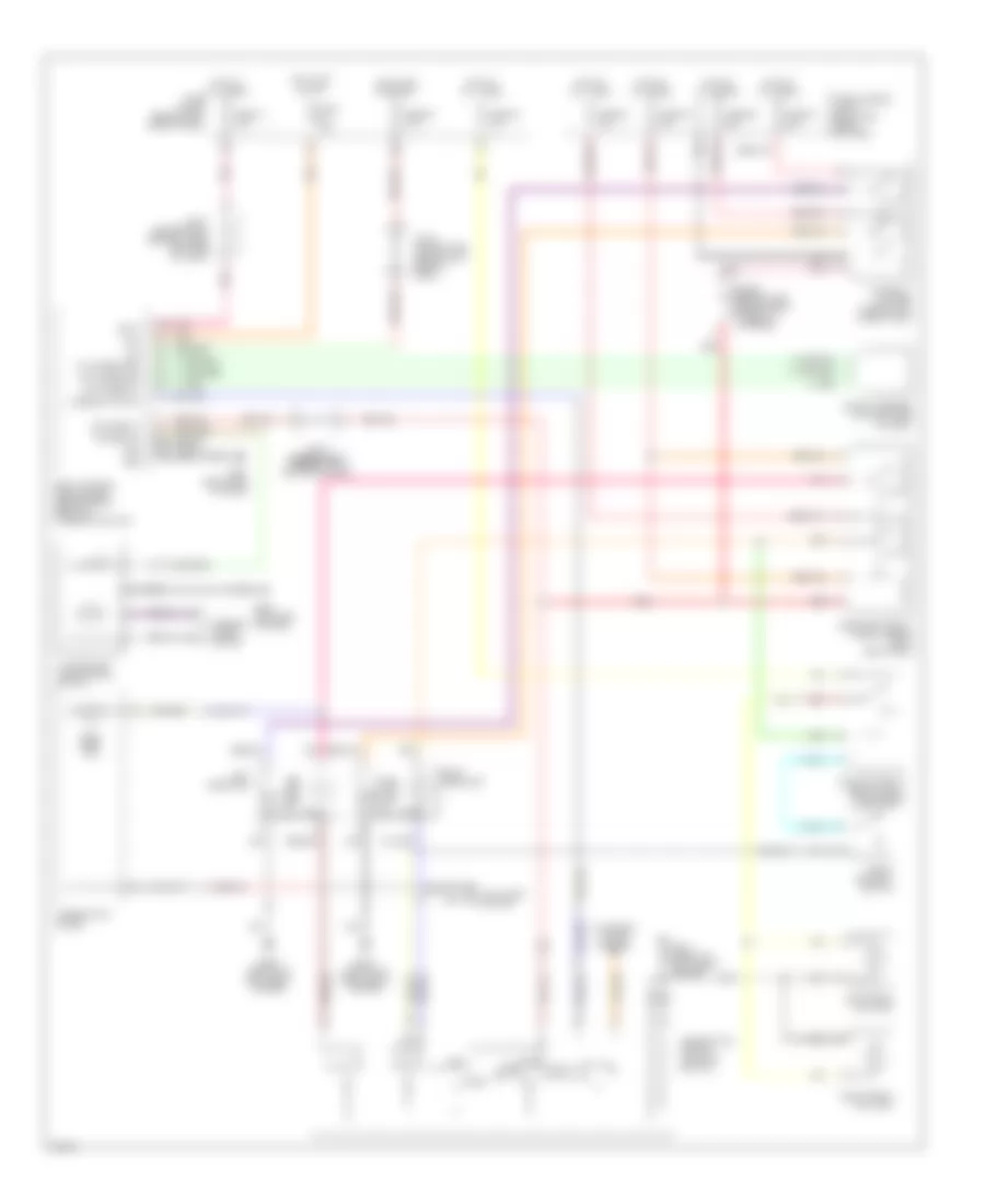
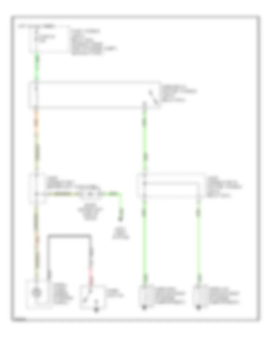
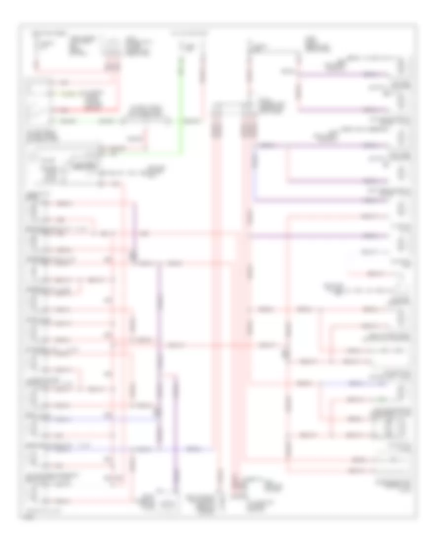
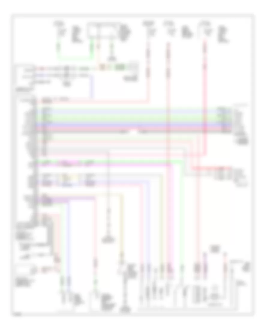
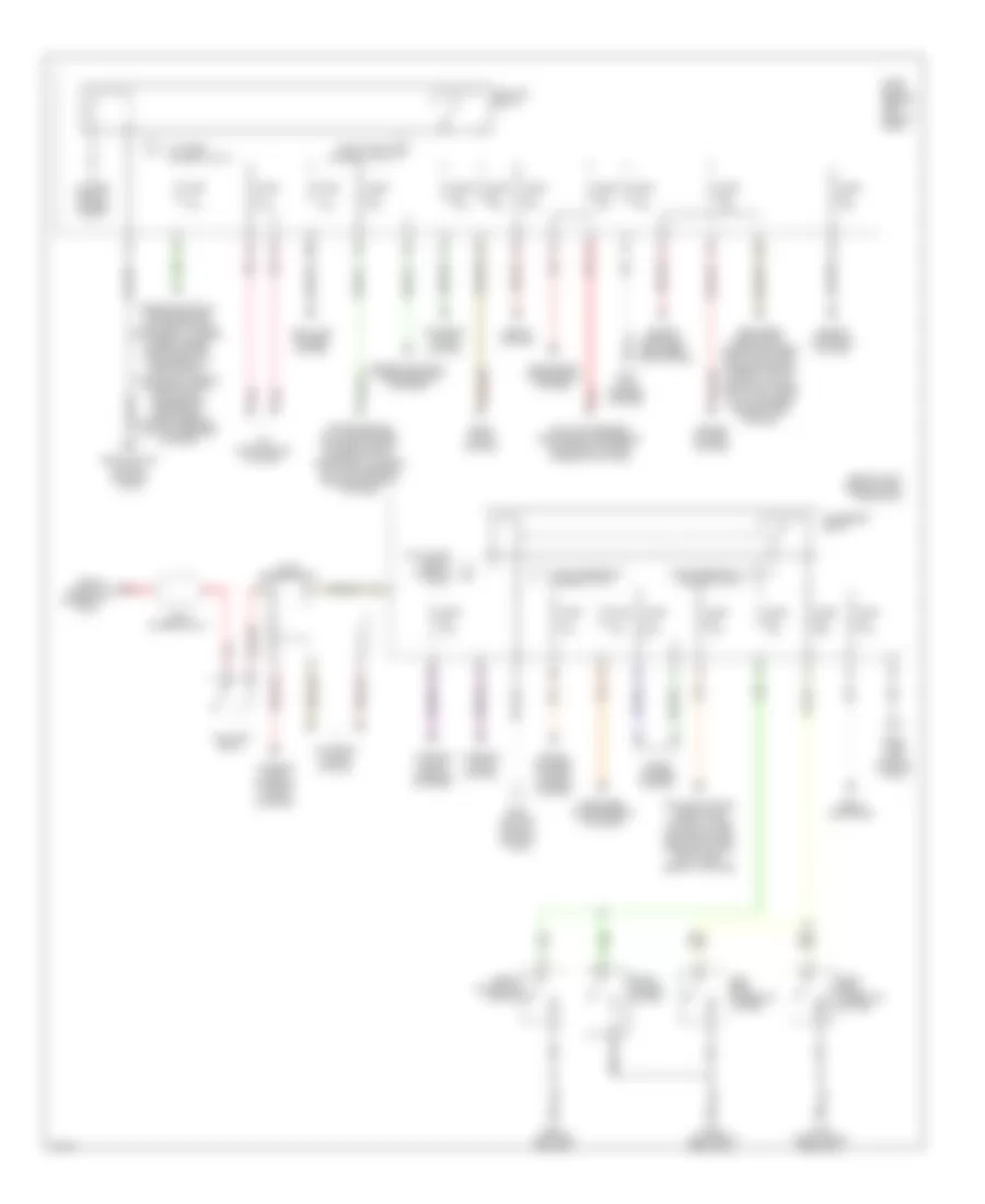
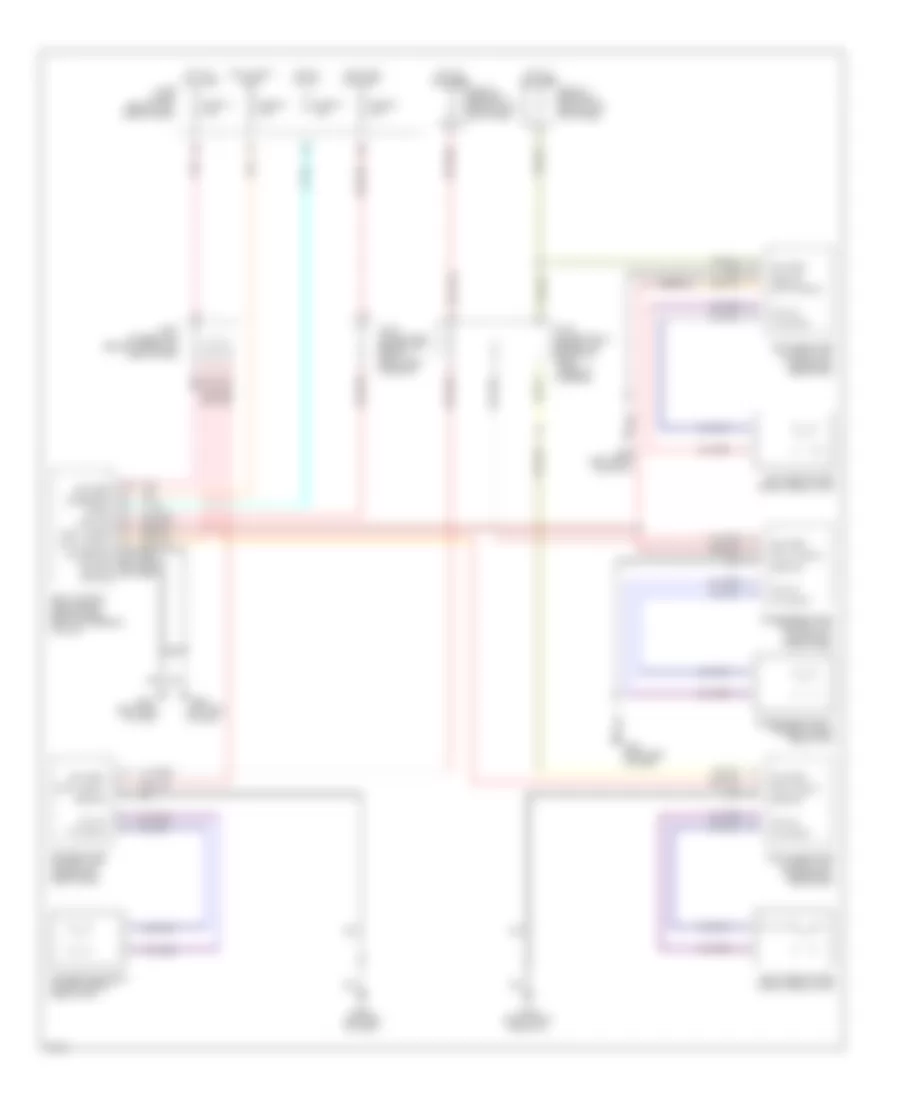
Automatic A/C Wiring Diagram (2 of 2) for Infiniti Q45 2000
List of elements for Automatic A/C Wiring Diagram (2 of 2) for Infiniti Q45 2000:
- A/c rly
- Air conditioner relay (at right rear corner of engine compt, behind strut tower)
- Air mix door motor (behind left side of center console, on heater unit)
- Arcon
- Bi-level door motor (behind right center of dash, on heater unit)
- Compressor
- Cooling fan motor 1
- Cooling fan motor 2
- Cooling fan relay 1 (in fuse, fusible link & relay box)
- Cooling fan relay 2 (in fuse, fusible link & relay box)
- Cooling fan relay 3 (at right front corner of engine compt, near left side of battery)
- Eccs control module (ecm) (behind right kick panel)
- Fuse 10a
- Fuse 7.5a
- Fuse block (behind left side of dash)
- Fuse f 40a
- Fuse i 40a
- Fuse, fusible link & relay box (in right front side of eng compt, near battery)
- G100 (left front of engine compt)
- G101 (right front of engine compt)
- Hot at all times
- Hot in on or start
- Lo hi norm
- Pnk
- Red
- Rfm1
- Rfm2
- Ta sw
- Triple-pressure switch (at left front of engine compt, on a/c liquid tank)
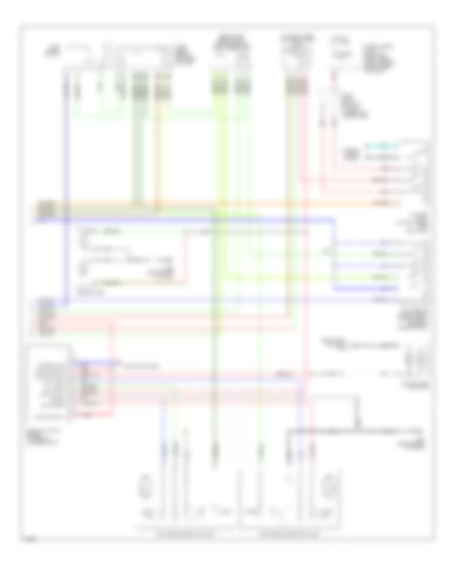
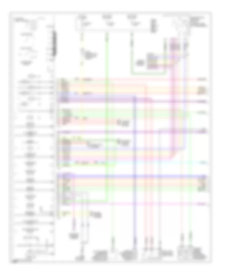
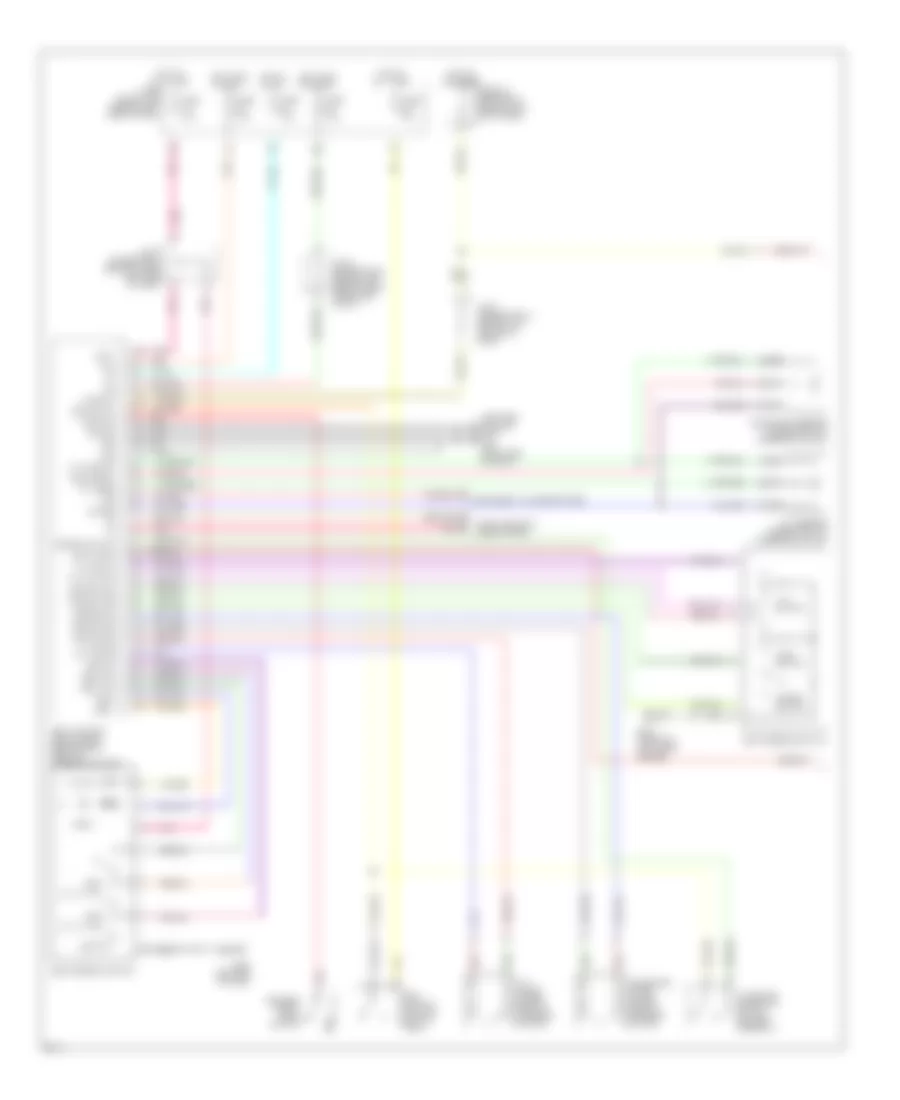
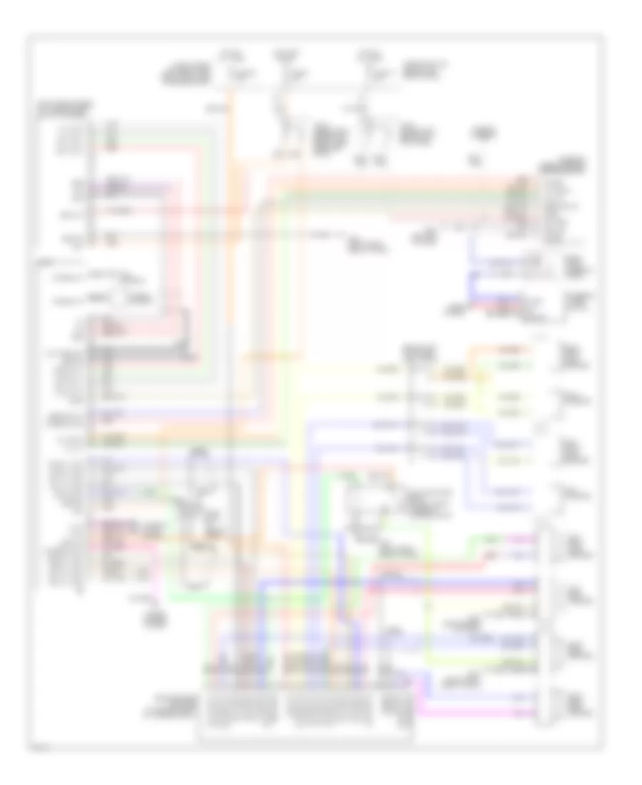
ANTI-LOCK BRAKES
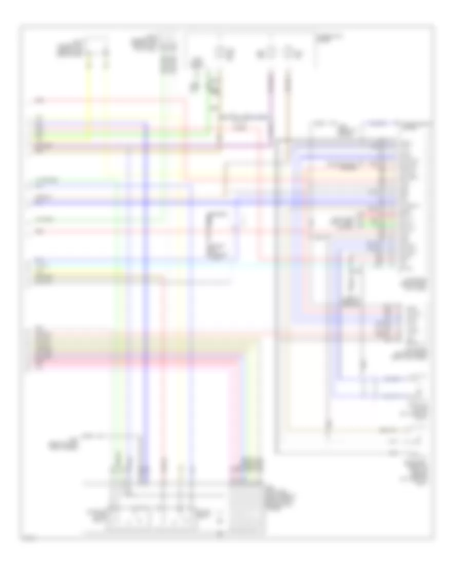
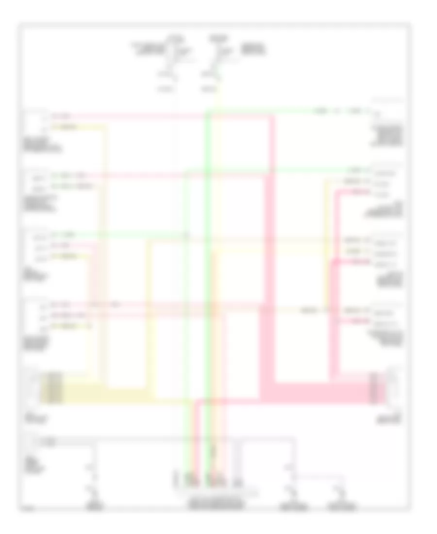
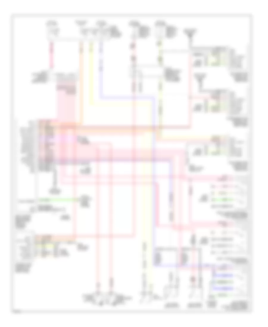
Anti-lock Brake Wiring Diagrams (1 of 2) for Infiniti Q45 2000
List of elements for Anti-lock Brake Wiring Diagrams (1 of 2) for Infiniti Q45 2000:
- (behind right kick panel) throttle motor relay
- (left end of dash) g202
- 16b
- Abs actr mon
- Abs actr rly
- Abs mtr mon
- Abs mtr rly
- Abs w/l
- Abs/tcs control unit (behind right side of dash)
- Ascd (cruise) control unit (behind dash, left of steering column)
- Bus-b
- Computer data lines system
- Consult rx
- Consult tx
- Diag-l
- Dkr
- Dkv
- Eccs tach
- Fuse 28 10a
- Fuse 30 10a
- Fuse 31 7.5a
- Fuse 34 7.5a
- Fuse 37 15a
- Fuse 4 7.5a
- Fuse 56 15a
- Fuse block (behind left side of dash)
- Fuse j 30a
- Fuse k 30a
- Fuse, fusible link & relay box (right front side of engine compt, near battery)
- G203 (right kick panel)
- Grd
- Grd-lan
- Hot at all times
- Hot in on or start
- Hot in start
- Joint connector 1 (behind left side of dash)
- Joint connector 6 (upper right side of dash)
- Left front wheel sensor
- Left rear wheel sensor
- Lft frt in
- Lft frt out
- Lft frt sens
- Lft rr sens
- Nca
- Pnk
- Red
- Right front wheel sensor
- Right rear wheel sensor
- Rr in sol
- Rr out sol
- Rt frt in
- Rt frt out
- Rt frt sens
- Rt rr sens
- Slip ind
- Stop lamp switch (brake pedal bracket)
- Stop sw
- Tcs active
- Tcs off ind
- Tcs sw
- Tcs switch
- Transmission control module (left kick panel)
- Vign
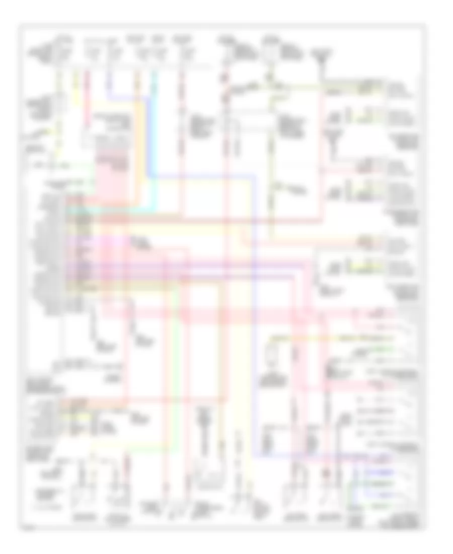
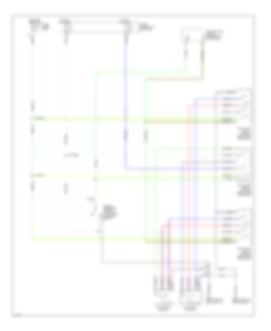
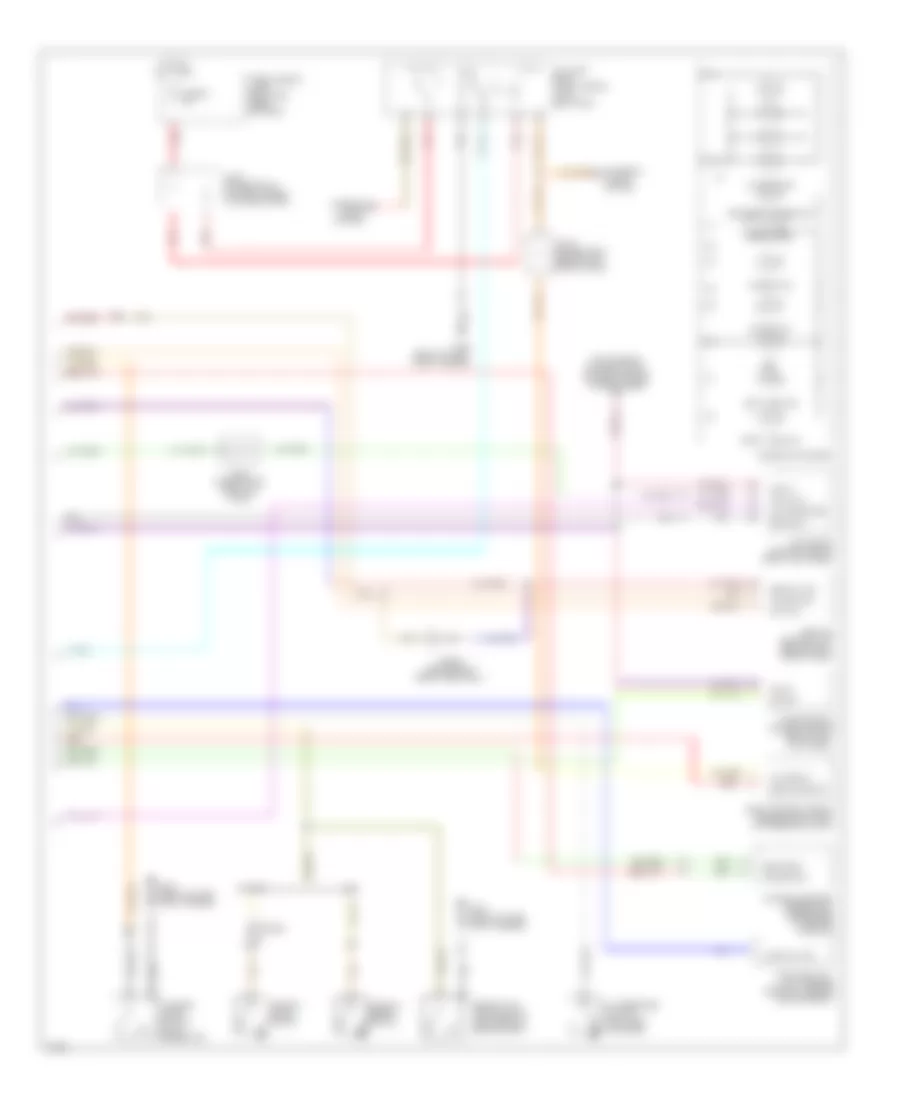
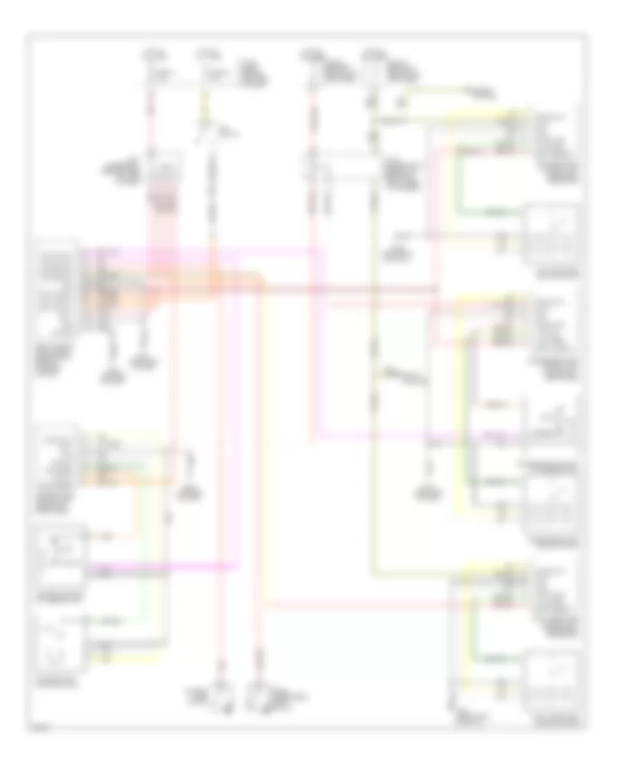
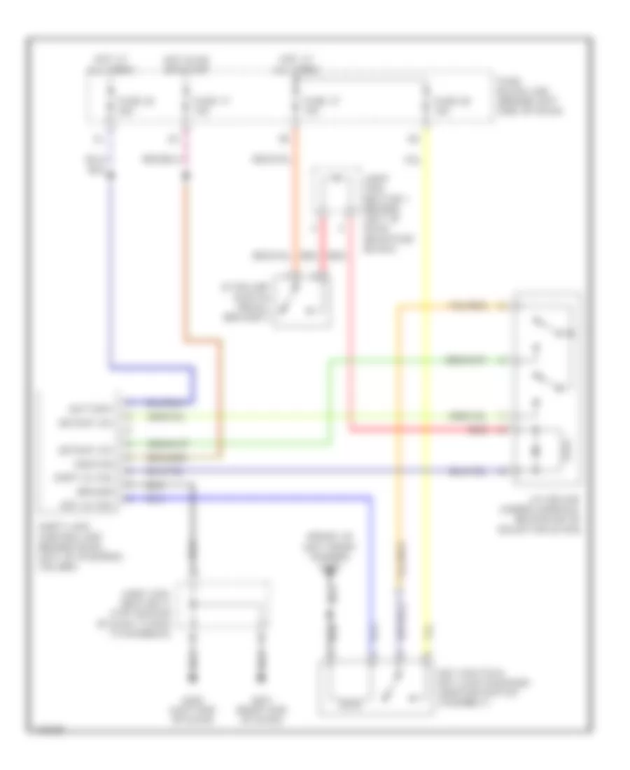
Anti-lock Brake Wiring Diagrams (2 of 2) for Infiniti Q45 2000
List of elements for Anti-lock Brake Wiring Diagrams (2 of 2) for Infiniti Q45 2000:
- (front of engine) g125
- Abs actuator (right rear of engine compt, behind strut tower)
- Abs ind
- Battery
- Combination meter
- Computer data lines system
- Diode
- Dkr
- Dkv
- Ecm (eccs) control module (right kick panel)
- G100 (front of left front fender)
- G125 (front of engine)
- Gnd
- Gnd-a
- Gnd-c
- Gnd-p
- Joint connector 1 (behind left side of dash)
- Joint connector 8 (behind left kick panel)
- Lan
- Motor 1
- Motor 2
- Motor relay
- Nca
- Neutral
- Pnk
- Red
- Sci clk
- Sci rx
- Sci tx
- Secondary throttle position sensor (on throttle body)
- Senp
- Slip ind
- Solenoid valve relay
- St sw
- Stps
- Stps out
- T/m relay
- Tac module (behind right kick panel)
- Tach signal input
- Tacho
- Tcs off ind
- Tcs sw
- Throttle motor (on throttle body)
- Transmissions system
- Tvo0
- Tvo1
- Vign
ANTI-THEFT
Anti-theft Wiring Diagram for Infiniti Q45 2000
List of elements for Anti-theft Wiring Diagram for Infiniti Q45 2000:
- (behind upper left side of dash) joint connector 4
- (front of left front fender) g100
- (left front door sill) g309
- (right end of dash) g201
- 16b
- 18b
- 37k
- 44r
- 63k
- A/d ground
- Accessory
- Ant
- Battery
- Between full stroke & neutral
- Body control module (bcm) (behind dash, right of steering column)
- Circuit breaker 1 (behind left kick panel)
- Circuit breaker 2 (behind left kick panel)
- Data line a1
- Data line a2
- Door lock
- Door locks system
- Door switch
- Door switich
- Door unlock
- Driver's door control unit (inside left front door)
- Driver's door switch
- Exterior lights system
- Front passenger's door switch
- Full stroke
- Fuse 10a
- Fuse 7.5a
- Fuse block (j/b) (behind left side of dash)
- G201 (right end of dash)
- G202 (left end of dash)
- G309 (left front door sill)
- G316 (right front door sill)
- Gnd
- Ground
- Hazard
- Head- lights system
- Hood switch
- Horns system
- Hot at all times
- Hot in on or accy
- Hot in on or start
- Hot in start
- Ignition
- Immobilizer circuit
- Joint connector 1 (behind left side of dash, near fuse box)
- Joint connector 12 (behind top center of dash, taped to harness)
- Joint connector 3 (behind left side of dash, near fuse box)
- Key switch
- Key switch (ignition switch assy)
- Left rear door control unit (inside left rear door)
- Left rear door switch
- Lock switch
- Memory systems
- Multi-remote control relay (right front corner of luggage compt)
- Nca
- Passenger's door control unit (inside right front door)
- Pnk
- Red
- Right rear door control unit (inside right rear door)
- Right rear door switch
- Seats system
- Security indicator
- Start
- Theft ind
- Theft relay
- Theft warning horn (left rear of engine compt)
- Theft warning horn relay (in luggage compt)
- Theft warning lamp relay (in fuse block)
- Trunk lid key cylinder switch
- Trunk room lamp switch
- Trunk switch
- Trunk unlk sw
- Unlock sens
- Unlock switch
- Window antenna
Immobilizer Wiring Diagram (NATS) for Infiniti Q45 2000
List of elements for Immobilizer Wiring Diagram (NATS) for Infiniti Q45 2000:
- (behind dash, right of steering column)
- (front of engine)
- 16b
- 18b
- Air conditioning system
- Body control module
- Ecm (eccs) control module (behind right kick panel)
- Fuse 28 10a
- Fuse 32 7.5a
- Fuse 57 7.5a
- Fuse block (j/b) (behind left side of dash)
- Fuse, fusible link & relay box (near battery)
- G125
- Hot at all times
- Hot in on or start
- Joint connector 1 (behind left side of dash, near fuse block)
- Joint connector 3 (behind left side of dash, near fuse block(
- Joint connector 6 (behind upper right side of dash, taped to harness)
- Nats antenna amp (in ignition key cylinder)
- Nats immu (under front of center console, near ashtray)
- Red
- Security indicator
BODY COMPUTER
Body Computer Wiring Diagrams for Infiniti Q45 2000
List of elements for Body Computer Wiring Diagrams for Infiniti Q45 2000:
- 18b
- A/d batt
- A/d gnd
- A/d grd
- Acc
- Ant
- Anti-theft system
- Auto sens
- Batt
- Belt sw
- Body control module (bcm) (behind dash, right of steering column)
- Cancel sw
- Chime
- Circuit breaker 2 (behind left kick panel)
- Combo sw
- Computer data lines system
- Console lt
- Data line a1
- Data line a2
- Data line a3
- Data link connector (consult) (under left side of dash, near hood release handle)
- Defog rly
- Defog sw
- Defoggers system
- Detent sw
- Door locks system
- Door sw
- Door warn
- Exterior lights system
- Foot light
- Fuse 14 7.5a
- Fuse 23 7.5a
- Fuse 32 7.5a
- Fuse 34 7.5a
- Fuse block (j/b) (behind left side of dash)
- G201 (right end of dash)
- G202 (left end of dash)
- Gnd
- Hazard
- Hdlt relay
- Headlights system
- Hood sw
- Hot at all times
- Hot in accy or on
- Hot in on or start
- Hot in start
- Ign
- Ign key
- Instrument cluster system
- Int (vr)
- Int lights
- Interior lights system
- Joint connector 12 (behind top center of dash)
- Joint connector 2 (behind left side of dash, near fuse block)
- Joint connector 3 (behind left side of dash, near fuse block)
- Joint connector 4 (behind upper left side of dash)
- Joint connector 8 (behind left kick panel)
- Key switch
- Light sw
- Map light
- Mem ind 1
- Mem ind 2
- Mem sw 1
- Mem sw 2
- Memory systems
- Nca
- Pers light
- Pnk
- Power tops system
- Red
- Sec ind
- Set sw
- Sunrf timer
- T/coord
- Tail relay
- Tele motor
- Tele sens
- Tele sw
- Theft
- Tilt motor
- Tilt sens
- Tilt sw
- Tilt/tele
- Trunk open
- Trunk release system
- Trunk sw
- Trunk unlk
- Unlock sw
- Vsp
- Warning systems
- Wash sw
- Wiper amp
- Wiper park
- Wiper/washer system
- Wipr int sw
COMPUTER DATA LINES
Computer Data Lines for Infiniti Q45 2000
List of elements for Computer Data Lines for Infiniti Q45 2000:
- 10k
- Abs/tcs control unit (behind right side of dash)
- Air bag diagnosis sensor unit (under rear of center console)
- Ascd control unit (behind dash, left of steering column)
- Body control module (bcm) (behind dash, right of steering column)
- Clock (hhc)
- Consult rx
- Consult tx
- Csr
- Cst
- Data link connector (dlc) (under left side of dash, near hood lock release handle)
- Diagnostic-l
- Eccs control module (ecm) (behind right kick panel)
- Fuse 2 10a
- Fuse 57 7.5a
- Fuse block (behind left side of dash)
- Fuse, fusible link & relay box (near battery)
- G100 (front of left front fender)
- G101 (front of right front fender)
- G125 (front of engine)
- Gst
- Hot at all times
- Hot in on or start
- J/c 2 (behind left side of dash)
- J/c 6 (behind upper right side of dash)
- J/c 8 (behind left kick panel)
- Pnk
- Power steering control unit (behind dash, right side of center console)
- Red
- Rx (hhc)
- Sci clk
- Sci rx
- Sci tx
- Sol
- Sss in (rx)
- Sss out (tx)
- Sss rx
- Sss tx
- Tac module (behind right kick panel)
- Transmission (tcm) control module (behind left kick panel)
- Tx (hhc)
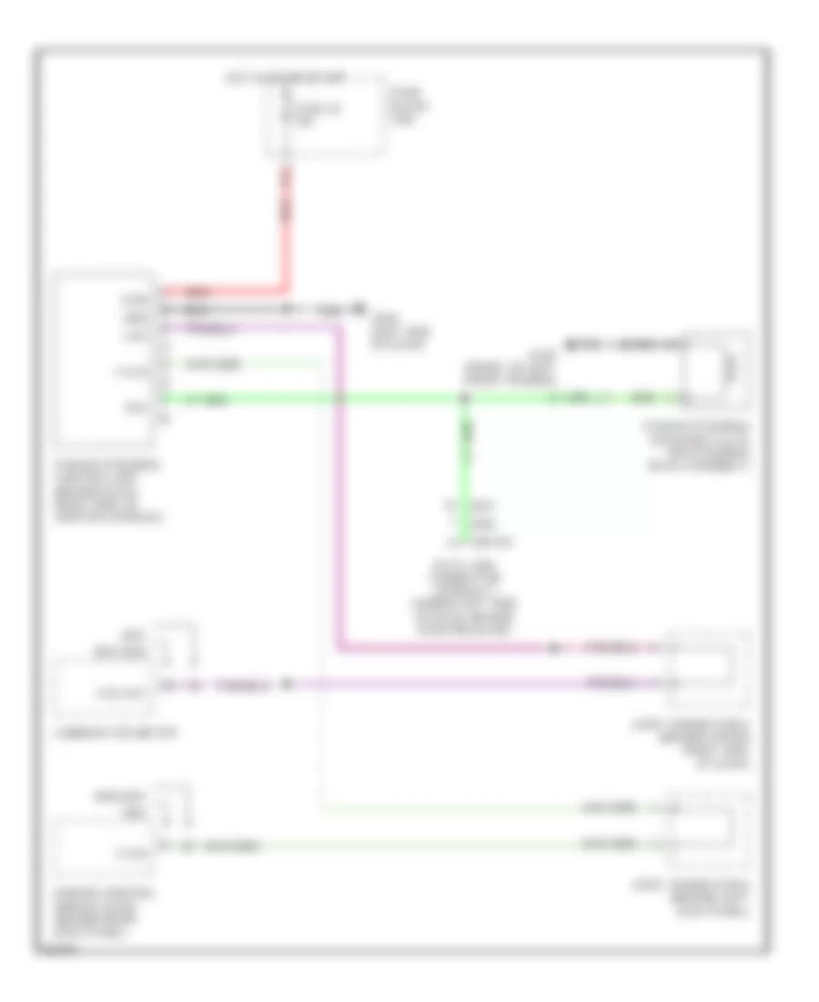
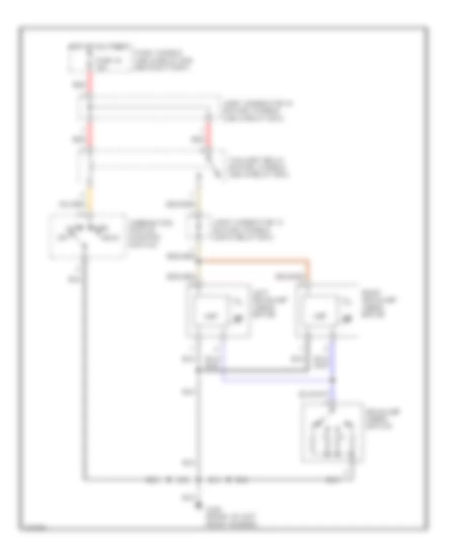
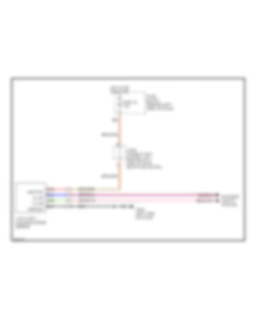
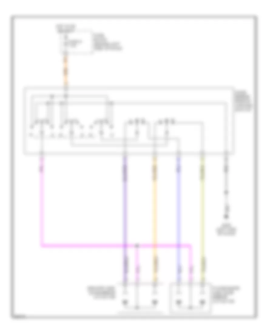
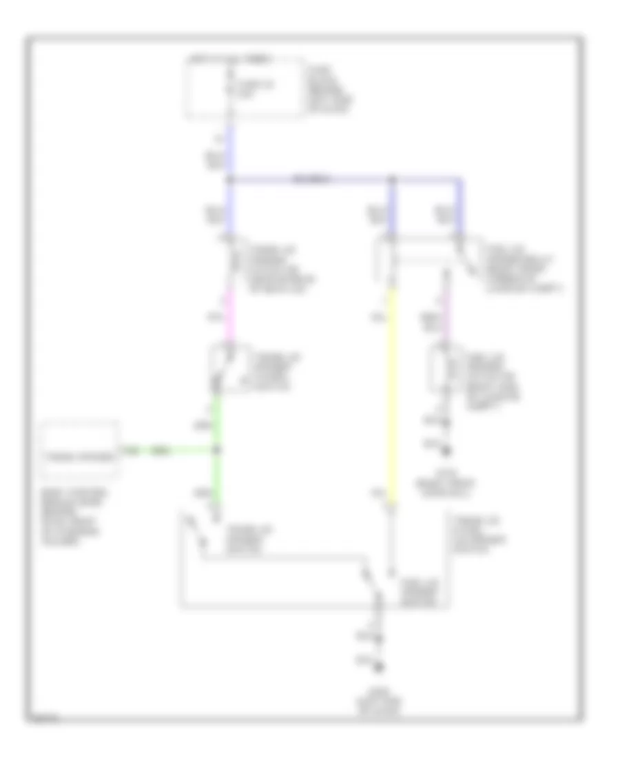
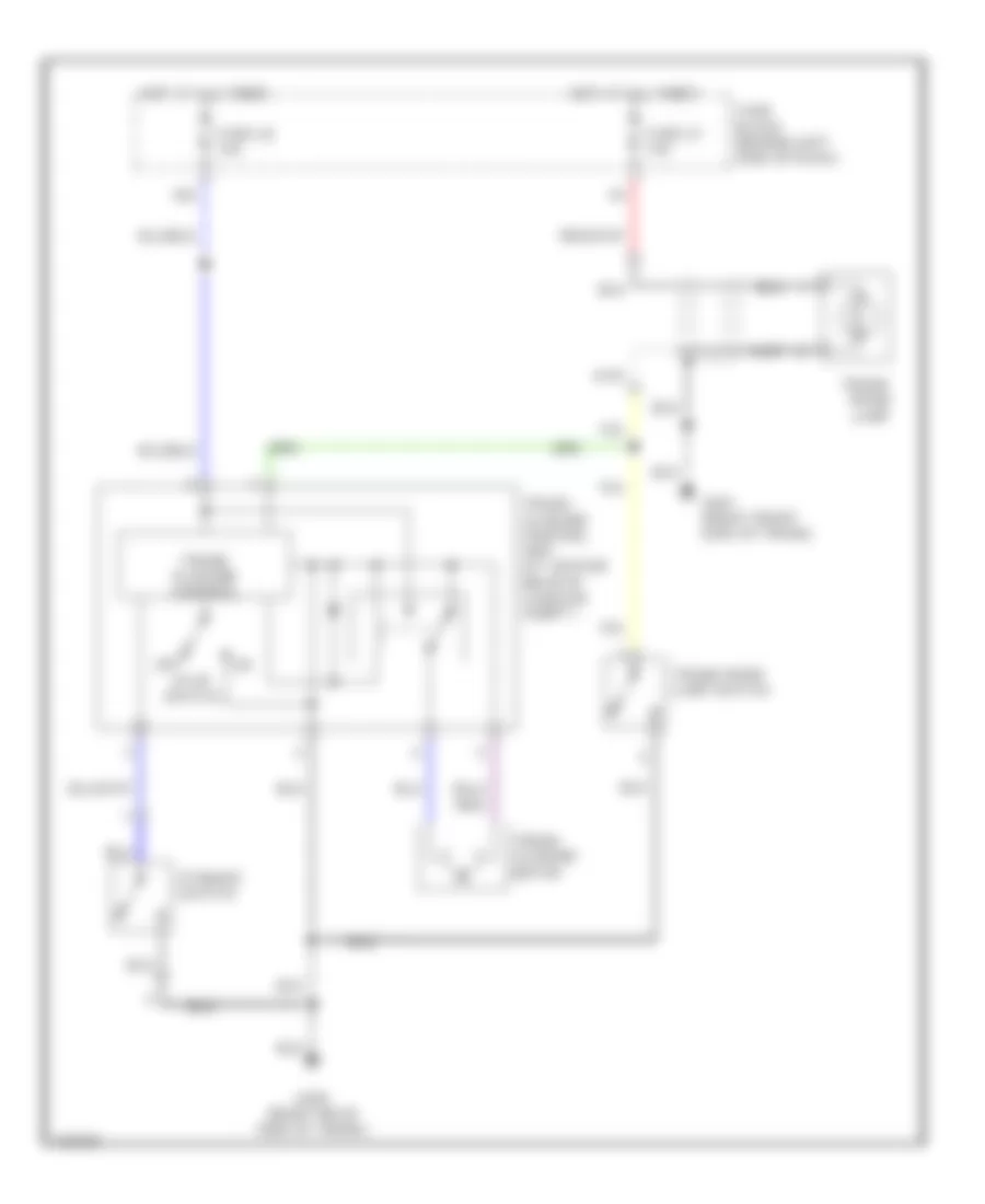
COOLING FAN
Cooling Fan Wiring Diagram for Infiniti Q45 2000
List of elements for Cooling Fan Wiring Diagram for Infiniti Q45 2000:
- Cooling fan motor 1
- Cooling fan motor 2
- Cooling fan relay 1 (in fuse & fusible link relay box)
- Cooling fan relay 2 (in fuse & fusible link relay box)
- Cooling fan relay 3 (in fuse & fusible link relay box)
- Eccs control module (behind right kick panel)
- Fuse & fusible link relay box
- Fuse 10a
- Fuse block (j/b)
- Fuse f 30a
- Fuse i 30a
- G100 (left front of engine compt)
- G101 (right front of engine compt)
- Hot at all times
- Hot in on or start
- Rfrh
- Rfrl
- Triple- pressure switch (left front of engine compt)
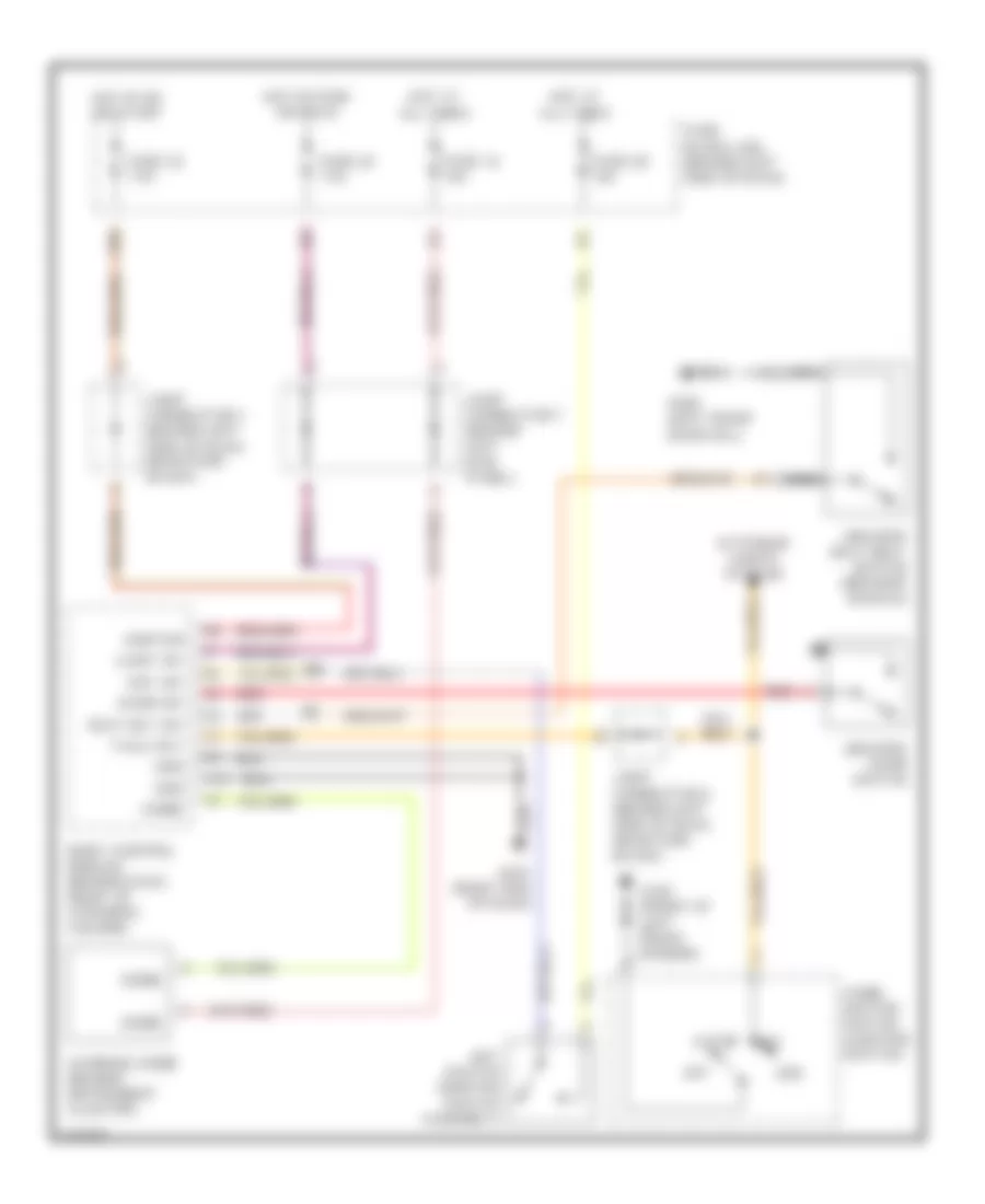
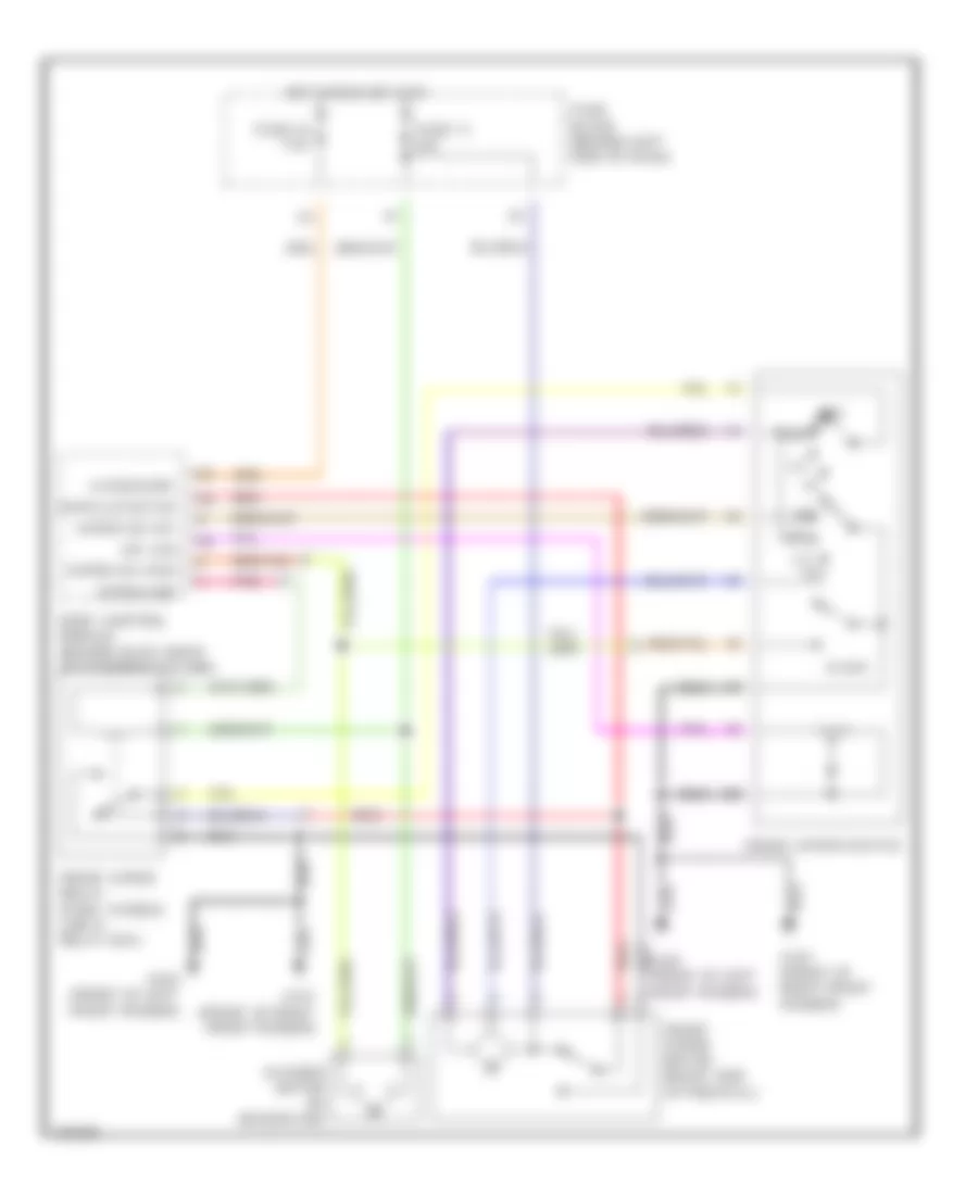
CRUISE CONTROL
Cruise Control Wiring Diagram for Infiniti Q45 2000
List of elements for Cruise Control Wiring Diagram for Infiniti Q45 2000:
- (1999)
- (2000)
- (2001)
- 13h
- 17b
- Abs/tcs control unit (behind right side of dash)
- Air valve
- Ascd brake switch (on bracket, above brake pedal)
- Ascd control unit (behind dash, left of steering column)
- Ascd hold unit (behind dash, right of steering column)
- Ascd pump (at left rear corner of engine compt)
- Ascd steering wheel switch
- Cancel
- Clock
- Combination meter
- Cruise ind
- Cruise lamp
- Data link connector (under left side of dash, beside hood lock release handle)
- Diode (under carpet, near driver's door sill)
- Engine controls system
- Fuse 18 10a
- Fuse 32 7.5a
- Fuse 37 15a
- Fuse 64 15a
- Fuse block
- Fuse, fusible link & relay box
- G101 (front of right front fender)
- G202 (left end of dash)
- Ground
- Horn relay (in fuse, fusible link & relay box)
- Hot at all times
- Hot in on or start
- Ignition
- Joint conn- ector 2 (near fuse block)
- Joint connector 1 (behind left side of dash, near fuse block)
- Joint connector 7 (behind left kick panel)
- Joint connector 8 (behind left kick panel)
- Main out
- Main sw
- Main switch
- Nc brake sw
- Nca
- No brake sw
- O/d cancel
- Park/neutral position relay (in fuse, fusible link & relay box)
- Park/neutral position switch (right side of transmission)
- Pnk
- Pump pwr
- Red
- Release valve
- Res/acc sw
- Resume/ accel
- Set ind
- Set/ coast
- Set/coast sw
- Speed sens
- Speed sig out
- Spiral cable
- Stoplight switch (on bracket above brake pedal)
- Tcs
- Transmission control module (behind left kick panel)
- Vac motor
DEFOGGERS
Defogger Wiring Diagram for Infiniti Q45 2000
List of elements for Defogger Wiring Diagram for Infiniti Q45 2000:
- (left end of dash) g202
- (right end of dash) g201
- 18b
- A/c control unit
- Air conditioning system
- Body control module (behind dash, right of steering column)
- Condenser
- Def sw
- Door mirror defogger relay (behind left kick panel)
- Driver's door mirror defogger
- Fuse 32 7.5a
- Fuse 38 15a
- Fuse 39 15a
- Fuse 9 7.5a
- Fuse block (j/b) (behind left side of dash)
- G201 (right end of dash)
- G202 (left end of dash)
- G309 (left front door sill)
- Grd
- Hot at all times
- Hot in on or start
- Hot in or or accy
- Ignition
- Joint connector 3 (behind left side of dash, near fuse block)
- Passenger's door mirror defogger
- Rear defog
- Rear window defogger
- Rear window defogger relay (behind left kick panel)
- Rear window defogger switch
ELECTRONIC POWER STEERING
Electronic Power Steering Wiring Diagram for Infiniti Q45 2000
List of elements for Electronic Power Steering Wiring Diagram for Infiniti Q45 2000:
- 1997-2000
- 1997-99
- 1998-2001
- Combination meter
- Data link connector (consult) (under left side of dash, beside hood release)
- Engine control module (ecm) (behind right kick panel)
- Fuse 30 10a
- Fuse block (j/b)
- G100 (front of left front fender)
- G202 (left end of dash)
- Grd
- Hot in on or start
- Joint connector 6 (behind upper right side of dash)
- Joint connector 8 (behind left kick panel)
- Power steering control unit (behind dash, right side of center console)
- Power steering solenoid valve (on steering rack assembly)
- Red
- Sol
- Tach
- Vign
- Vsp
- Vss out
ELECTRONIC SUSPENSION
Electronic Suspension Wiring Diagram for Infiniti Q45 2000
List of elements for Electronic Suspension Wiring Diagram for Infiniti Q45 2000:
- (2000 only)
- (left front of trunk) g400
- 16b
- Active damper suspension control unit (under left side of rear package shelf)
- Active damper suspension select switch
- Actr lf b
- B89
- B90
- Bat
- Combination meter
- Data link connector (under left side of dash, near hood lock release handle)
- Eccs control module (behind right kick panel)
- Electronic power steering system
- Eps sol
- Fpc conn
- Fr com actr
- Front vertical g sensor (near driver's side lower instrument panel)
- Fuse 28 10a
- Fuse 30 10a
- Fuse 37 15a
- Fuse 4 7.5a
- Fuse block (behind left side of dash)
- G sens f gnd
- G sens f in
- G sens lr in
- G sens rr in
- G101 (front of right front fender)
- G102 (left front shock tower)
- G103 (right front shock tower)
- G202 (left end of dash)
- G309 (left front door sill)
- G316 (right front door sill)
- Gnd 1
- Gnd 2
- Gnd 3
- Gsens f pwr
- Hot at all times
- Hot in on or start
- Ign 1
- Ign 2
- Ign 3
- Ign 4
- Ind
- Interior lights system
- Joint connector (behind left side of dash)
- Joint connector 8 (left kick panel)
- Left front shock absorber actuator
- Left rear shock absorber actuator
- Left rear vertical g sensor (2000 only) (left front side of luggage compartment)
- Lf actr a
- Lf actr b
- Lr actr a
- Lr actr b
- Pnk
- Power steering solenoid vavle (on steering rack assembly)
- Red
- Rf actr a
- Rf actr b
- Right front shock absorber actuator
- Right rear shock absorber actuator
- Right rear vertical g sensor (right front side of luggage compartment)
- Rr actr a
- Rr actr b
- Rr actr com
- Select
- Solid state
- Speed sens
- Sport ind
- Steering wheel angle sensor (at top of steering column)
- Stop sw
- Stop- light switch (on bracket above brake pedal)
- Strg sen 1
- Strg sen 2
- Strg sen neu
- Tacho
- Transmission control system
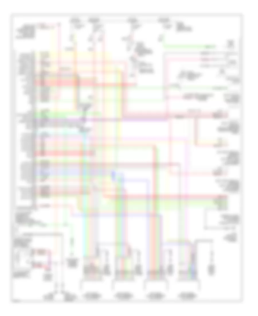
ENGINE PERFORMANCE
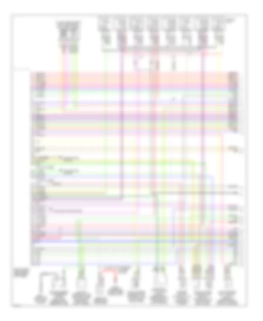
4.1L
4.1L, Engine Performance Wiring Diagrams (1 of 4) for Infiniti Q45 2000
List of elements for 4.1L, Engine Performance Wiring Diagrams (1 of 4) for Infiniti Q45 2000:
- (30-33 not used)
- (37-40 not used)
- (front of right front fender)
- (on left front side of eng, forward of left throttle body) iacv-aac valve
- Air conditioning system
- Check connector (in right rear of eng compt)
- Cooling fans system
- Eccs control module (ecm) (behind right kick panel)
- Evap canister purge control solenoid valve (on top right rear of eng)
- Evap canister purge volume control solenoid valve (on top right rear of eng)
- Evap canister vent control valve (under right rear of vehicle, on evap canister)
- G101
- Iacv-ficd solenoid valve (left front side of eng compt, forward of throttle body)
- Ignition coils
- Instrument cluster system
- Map/baro switch solenoid valve (on top center rear of eng)
- Pnk
- Power steering oil pressure switch (on power steering high pressure tube)
- Red
- Resistor (behind right kick panel)
- Vacuum cut valve bypass valve (under right rear of vehicle, forward of evap canister)
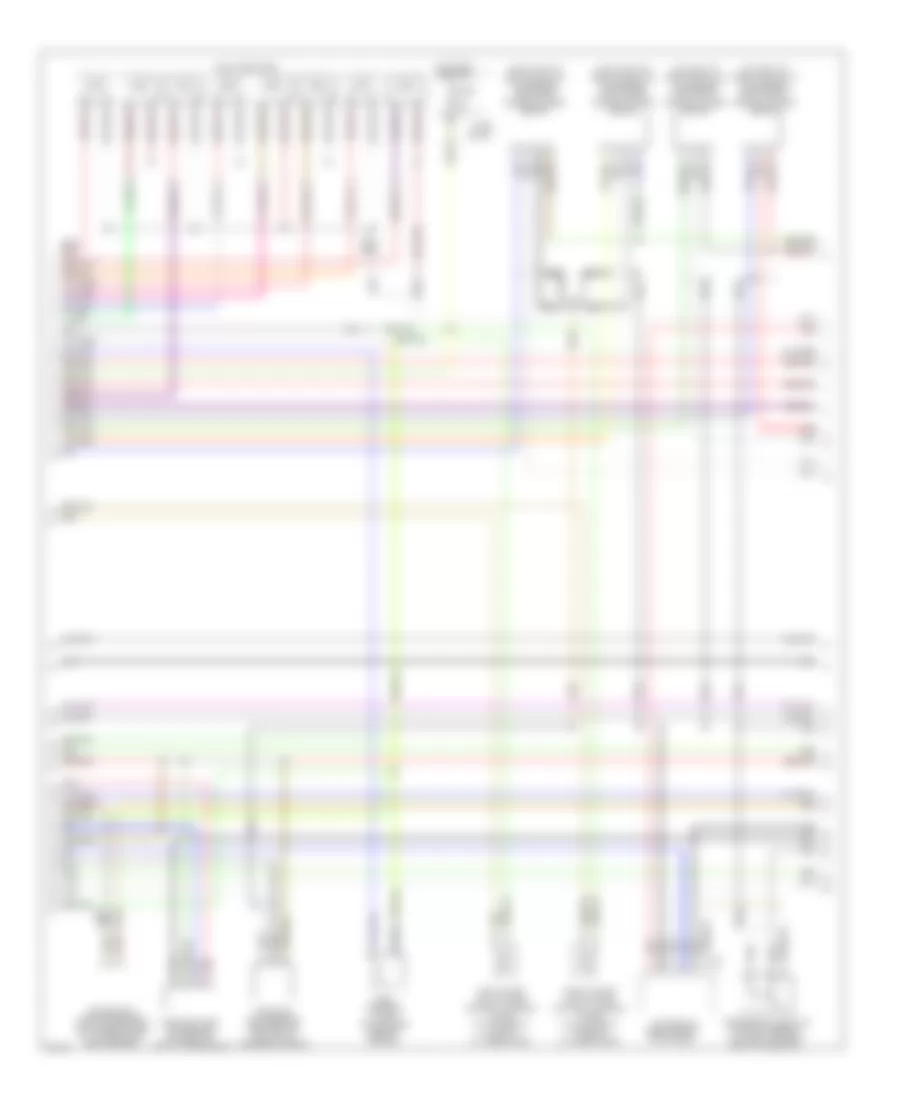
4.1L, Engine Performance Wiring Diagrams (2 of 4) for Infiniti Q45 2000
List of elements for 4.1L, Engine Performance Wiring Diagrams (2 of 4) for Infiniti Q45 2000:
- tac module (behind right kick panel)
- (on inlet of left catalytic converter) left front heated oxygen sensor
- (on inlet of right catalytic converter) right front heated oxygen sensor
- (on outlet of left catalytic converter) left rear heated oxygen sensor
- (on outlet of right catalytic converter) right rear heated oxygen sensor
- Camshaft posi- tion sensor (on front of left cylinder head)
- Crankshaft position sensor (bottom right side of transmission bellhousing)
- Egrc solenoid valve (top center rear of engine)
- F75
- Fuel injectors
- Fuse 10a
- Fuse block
- Hot in on or start
- Left intake valve timing control solenoid valve (on top front of left cylinder head)
- Mass air- flow sensor (between air duct & air cleaner housing)
- Nca
- Pnk
- Red
- Right intake valve timing control solenoid valve (on top front of right cylinder head)
- Secondary throttle position sensor (on throttle body, next to air duct)
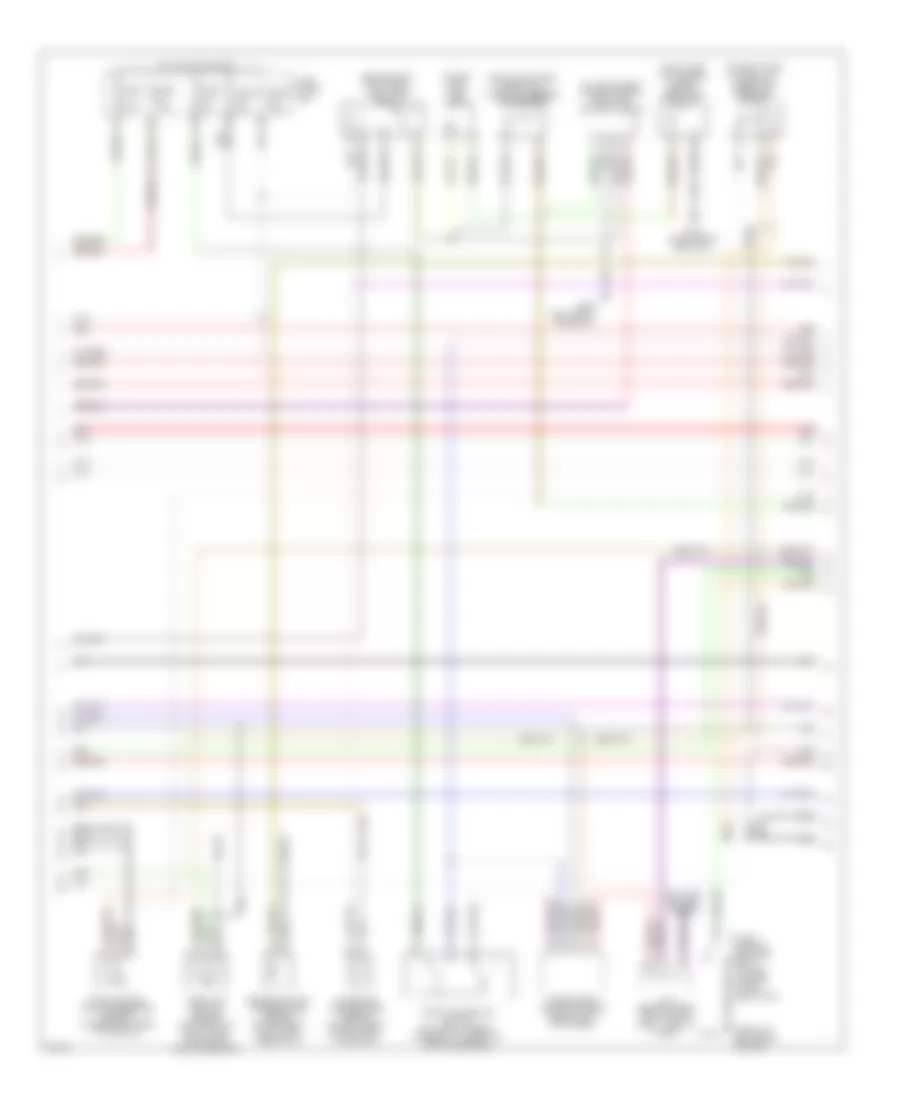
4.1L, Engine Performance Wiring Diagrams (3 of 4) for Infiniti Q45 2000
List of elements for 4.1L, Engine Performance Wiring Diagrams (3 of 4) for Infiniti Q45 2000:
- (above left rear wheelwell, taped to harness) condenser
- (behind right kick panel) fuel pump relay
- (front of left front fender)
- (in fuel tank) fuel pump
- (on left side of luggage compt) fuel pump control module
- (on right side of firewall) absolute pressure sensor
- (right side of luggage compt) dropping resistor
- 12g
- 15b
- Anti-lock brakes system
- Engine coolant temperature sensor (on top right fonr of eng, near inj 2)
- Evap control system pressure sensor (under right rear of vehicle)
- Fuse 10a
- Fuse 15a
- Fuse 7.5a
- Fuse block (j/b)
- G100
- G309 (left front door sill)
- G316 (right front door sill)
- Hot in on or start
- Intake air temperature sensor (on left front of eng compt, in air duct)
- J/c 6 (behind upper right side of dash, tape to harn)
- Nca
- Park/ neutral position relay (in fuse, fusible link & relay box)
- Red
- Throttle position sensor (on throttle body, near intake mani- fold collector)
- Throttle position switch (on throttle body, integral to throttle position sensor)
- Transmission control module (behind left kick panel)
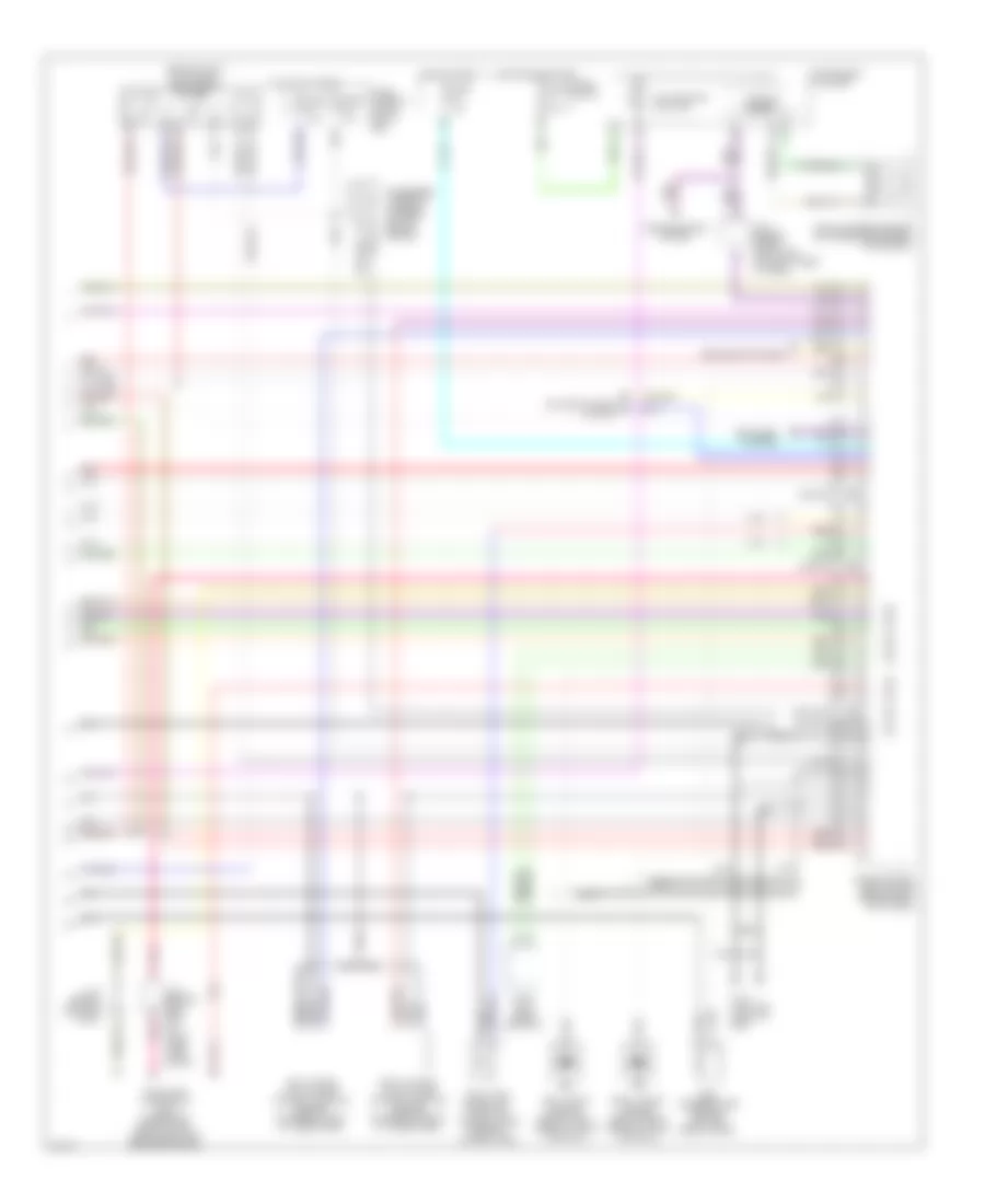
4.1L, Engine Performance Wiring Diagrams (4 of 4) for Infiniti Q45 2000
List of elements for 4.1L, Engine Performance Wiring Diagrams (4 of 4) for Infiniti Q45 2000:
- (104 not used)
- (107 not used)
- (109-120 not used)
- (84-88 not used)
- (94-95 not used)
- (behind right kick panel) eccs relay
- Air conditioning system
- Condenser (taped to harness, on right side of engine)
- Data link connector (dlc) (under left side of dash, near hood lock release handle)
- Defogger system
- Eccs control module (ecm) (behind right kick panel)
- Egr temperature sensor (top left rear of eng)
- Fuel tank gauge unit (tank fuel temperature sensor) (in fuel tank)
- Fuse 10a
- Fuse 7.5a
- Fuse block
- Fuse, fusible link & relay box
- G110 (top left front of eng)
- Headlights system
- Hot at all times
- Hot in on or start
- Hot in start
- Instrument cluster
- J/c 2 (behind left side of dash, near fuse block)
- J/c 6 (behind upper right side of dash, taped to harn)
- J/c 8 (behind left kick panel)
- Left intake valve timing control position sensor (on rear of left cylinder head)
- Left knock sensor (below left side of intake manifold)
- Malfunction ind lamp
- Nats immu (near ashtray)
- Nca
- Pnk
- Red
- Right intake valve timing control position sensor (on rear of right cylinder head)
- Right knock sensor (below right side of intake manifold)
- Speedo- meter
- Transmissions system
- Vehicle speed sensor (on transmission rear extension)
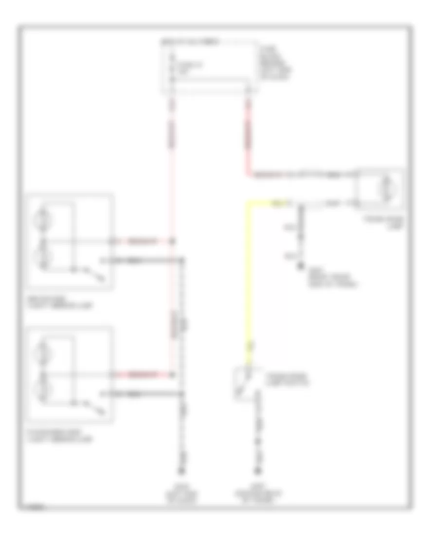
EXTERIOR LIGHTS
Backup Lamps Wiring Diagram for Infiniti Q45 2000
List of elements for Backup Lamps Wiring Diagram for Infiniti Q45 2000:
- 13h
- Exterior lights circuit
- Fuse 18 10a
- Fuse block (behind left side of dash)
- G309 (left front door sill)
- G400 (left front side of trunk)
- G407 (center rear of trunk)
- Hot in on or start
- Left back-up lamp
- Park/neutral position switch (on right side of transmission)
- Right back-up lamp
Exterior Lamps Wiring Diagram (1 of 2) for Infiniti Q45 2000
List of elements for Exterior Lamps Wiring Diagram (1 of 2) for Infiniti Q45 2000:
- (front of left front fender) g100
- (front of right front fender) g101
- (on bracket, above the brake pedal) stoplight switch
- 18b
- A/d gnd
- Acc
- Auto
- Batt
- Body control module (bcm) (behind dash, right of steering column)
- Combination flasher unit (behind dash, right of steering column)
- Combination meter
- Combination switch (lighting switch)
- Fuse 13 10a
- Fuse 14 7.5a
- Fuse 19 7.5a
- Fuse 32 7.5a
- Fuse 37 15a
- Fuse 7.5a
- Fuse block (behind left side of dash)
- G201 (right end of dash)
- G202 (left end of dash)
- Gnd
- Hazard
- Hazard switch
- Head
- Hot at all times
- Hot in on or accy
- Hot in on or start
- Ign
- Interior lights system
- Joint connector 1 (behind left side of dash, near fuse block)
- Joint connector 2 (behind left side of dash, near fuse block)
- Joint connector 3 (behind left side of dash, near fuse block)
- Joint connector 4 (behind upper left side of dash)
- Left
- Left front combination lamp
- Light sw (auto)
- Off
- Park
- Park/ turn
- Pnk
- Red
- Right
- Right front combination lamp
- Taillight relay
Exterior Lamps Wiring Diagram (2 of 2) for Infiniti Q45 2000
List of elements for Exterior Lamps Wiring Diagram (2 of 2) for Infiniti Q45 2000:
- (behind left side of dash, near fuse block) joint connector 3
- (in fuse, fusible link & relay box) joint connector 13
- (right front door sill) g316
- 10b
- 11g
- 12h
- 16h
- Fuse 63 15a
- Fuse block (behind left side of dash)
- Fuse, fusible link & relay box (right front side of engine compt, near battery)
- G407 (center rear of trunk)
- Ground
- H/mtg stop lmp
- High mounted stop lamp
- Hot at all times
- Interior lights system
- Joint conn- ector 15 (in fuse, fusible link & relay box)
- Left rear combination lamp
- License lamps
- Light sw tail
- Multi-remote control relay (in right front corner of luggage compt)
- Nca
- Red
- Right rear combination lamp
- Stop & taillight sensor (in rear of luggage compt)
- Stop lamp a
- Stop/ tail
- Stoplamp sw a
- Stoplamp sw b
- Tail
- Tail lamp c
- Tail lamp d
- Taillight relay (in fuse, fusible link & relay box)
- Turn
- Turn signal switch
- Warning lamp
- Warning systems
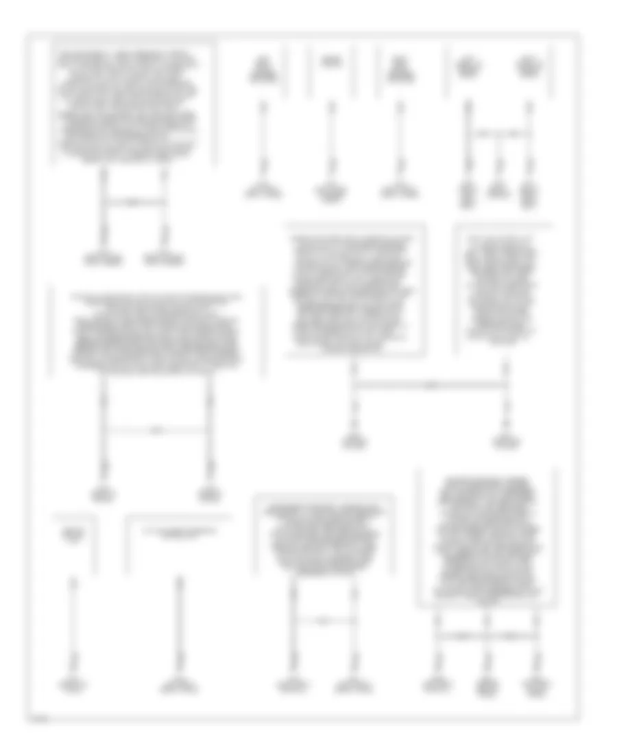
GROUND DISTRIBUTION
Ground Distribution Wiring Diagram for Infiniti Q45 2000
List of elements for Ground Distribution Wiring Diagram for Infiniti Q45 2000:
- (w/ xenon), right headlamp aiming motor, key
- 2, cooling fan motor 1, steering wheel angle
- A/t device, ascd hold
- Abs/tcs control unit
- Active damper suspension control unit
- Air mix door motor, a/c
- Amp, headlamp aiming switch, cooling fan motor
- Ascd control unit, bcm, air bag
- Auto amp
- Combination flasher unit,
- Combination lamp (w/o xenon), left front
- Combination lamp (w/o xenon), triple-pressure
- Combination lamp (w/xenon), left headlamp aiming
- Combination meter, front cigarette lighter,
- Combination switch, front wiper switch, a/c auto
- Condenser, ignition coil/power transistors 1-8, throttle
- Control switch, clock, rear sunshade
- Control switch, steering wheel receiver
- Cooling fan relay 1, right headlamp (w/ xenon), cooling fan relay 3, front wiper relay, taillight
- Defogger, right front
- Diagnosis sensor unit
- Door key cylinder
- Door motor, bi-level
- Door motor, power
- Driver's door control unit, right door
- Driver's power seat harness, front power socket, driver's seat heater switch, passenger's seat heater switch, door mirror defogger relay, left rear ashtray illumination, left rear door control unit, left rear cigarette lighter, left rear door lock actuator, left rear door switch, left rear speaker, ivcs unit, striker switch, handset, receiver, power antenna timer & motor, fuel pump control module, left rear combination lamp, license lamps, left rear shock absorber actuator, right rear combination lamp, trunk lid key cylinder switch, stop & taillamp sensor, trunk room lamp switch, active damper suspension control unit, left & right back-up lamps, left & right shock absorber actuator shields, trunk closure control unit, ivcs unit
- Engine ground
- G100 (front of left front fender)
- G101 (front of right front fender)
- G101 (right front of engine compt)
- G102 (left front strut tower)
- G103 (right front strut tower)
- G125 (front of engine)
- G201 (right end of dash)
- G202 (left end of dash)
- G203 (right kick panel)
- G300 (below left front seat)
- G301 (below right front seat)
- G302 (below console)
- G309 (left front door sill)
- G316 (right front door sill)
- G400 (left front side of trunk)
- G401 (right front side of trunk)
- G407 (center rear of trunk)
- Glove box lamp switch, fan control amp, intake
- Inside mirror, right vanity mirror lamp,
- Integrated homelink transmitter, left rear personal lamp, right rear personal lamp,
- Ivcs switch, left vanity mirror lamp &
- Left front shock absorber actuator
- Left satellite sensor shield
- Light control unit, right front combination lamp
- Link connector, adp steering switch,
- Lock actuator, bcm,
- Mirror defogger, seat memory switch, left front door key cylinder switch, left front door lock actuator, door
- Mirror remote control switch, trunk lid & fuel lid opener switch, left front door outside handle switch, fuse block,
- Mode door motor,
- Motor shield, abs/tcs control unit shield
- Motor, front wiper motor, abs actuator, power
- Passenger's power seat harness, right rear ashtray illumination, right rear door control unit, right rear cigarette lighter, right rear door lock actuator, right rear door switch, high mounted stop lamp, rear sunshade unit, right rear speaker, dropping resistor, audio amplifier relay, theft warning horn relay, fuel lid opener actuator, cd auto changer, trunk room lamp shield, rear sunshade unit shield, right rear shock absorber actuator
- Pressure switch, brake fluid level switch, data
- Relay, park/neutral position relay, washer level
- Right front shock absorber actuator
- Right satellite sensor shield
- Select switch, illumination time control
- Sensor, left headlamp (w/ xenon)
- Shift lock control unit,
- Steering control unit,
- Steering solenoid valve, power steering oil
- Switch & key lock solenoid, left front
- Switch, a/c control unit, illumination
- Switch, interior lamp, auto anti-dazzling
- Switch, left front fog lamp, hood switch, daytime
- Switch, right front door
- Switch, right front fog lamp, right front
- Tac module, secondary throttle position sensor shield, ecm, transmission control module, data link connector, nats immu, right & left intake valve timing control position sensors, right & left front heated oxygen sensor shields, crankshaft position sensor shield, right & left intake valve timing control position sensor shields, left & right knock sensor shields, absolute pressure sensor shield, evap control system pressure sensor shield, left & right rear heated oxygen sensors, left & right rear heated oxygen sensor shields, camshaft position sensor shield, camshaft position sensor, mass airflow sensor shield, throttle position sensor shield,
- Tcs switch, active damper suspension
- Unit, theft warning lamp relay, spiral cable, right front door control unit, right front door mirror
HEADLIGHTS
Headlamp Aiming Wiring Diagram for Infiniti Q45 2000
List of elements for Headlamp Aiming Wiring Diagram for Infiniti Q45 2000:
- Amp
- Auto
- Combination switch (lighting switch)
- Fuse 63 15a
- Fuse, fusible link & relay box (near battery)
- G100 (front of left front fender)
- Head
- Headlamp aiming switch
- Hot at all times
- Joint connector 13 (in fuse, fusible link & relay box)
- Joint connector 15 (in fuse, fusible link & relay box)
- Left headlamp aiming motor
- Off
- Park
- Red
- Right headlamp aiming motor
- Taillight relay (in fuse, fusible link & relay box)
Headlamps & Fog Lamps Wiring Diagram, with DRL, with Xenon Lamps for Infiniti Q45 2000
List of elements for Headlamps & Fog Lamps Wiring Diagram, with DRL, with Xenon Lamps for Infiniti Q45 2000:
- (behind top center of dash)
- (front of left front fender g100
- (front of right front fender g101
- 10d
- 18b
- Acc
- Alt-l
- Anti-theft system
- Auto
- Auto sens 5v
- Auto sens grd
- Auto sens sig
- Batt
- Body control module (bcm) (behind dash, right of steering column)
- Combination meter
- Combination switch (lighting switch)
- Combo sw (auto)
- Daytime light control unit (left side of engine compt)
- Diode (behind top left side of dash, taped to harness)
- Exterior lights system
- Foglight relay (behind right kick panel)
- Front foglight switch
- Fuse 15a
- Fuse 20a
- Fuse 7.5a
- Fuse block (behind left side of dash)
- Fuse, fusible link & relay box (near battery) compt)
- G100 (front of left front fender)
- G201 (right end of dash)
- G202 (left end of dash)
- Gnd
- Ground
- Hdlp relay
- Head
- Headlight relay (fuse, fusible link & relay box)
- Hid
- Hid relay (in fuse, fusible link & relay box)
- High
- High beam ind
- Hot at all times
- Hot in on or acc
- Hot in on or start
- Hot in start
- Ign
- Ignition
- Illumination time control switch
- Interior lights system
- Joint connector 10
- Joint connector 3 (behind left side of dash)
- Joint connector 4 (behind upper left side of dash)
- Left front foglight
- Left headlamp
- Lft hi beam
- Lft lite
- Lft lite fus
- Lft lite hi
- Low
- Nca
- Off
- Only
- Optical sensor (top left side of dash)
- Park
- Park brk sw
- Parking brake switch (park lever)
- Pass
- Pnk
- Red
- Right front foglight
- Right headlamp
- Rt hi beam
- Rt lite
- Rt lite fus
- Rt lite hi
- Start
- Starting/ charging system
- T/coord vr
- Warnings system
Headlamps & Fog Lamps Wiring Diagram, with DRL, without Xenon Lamps for Infiniti Q45 2000
List of elements for Headlamps & Fog Lamps Wiring Diagram, with DRL, without Xenon Lamps for Infiniti Q45 2000:
- (behind top center of dash)
- 10d
- 18b
- Acc
- Alt-l
- Anti-theft system
- Auto
- Auto sens 5v
- Auto sens grd
- Auto sens sig
- Batt
- Body control module (bcm) (behind dash, right of steering column)
- Combination meter
- Combination switch (lighting switch)
- Combo sw (auto)
- Daytime light control unit (left side of engine compt)
- Exterior lights system
- Foglight relay (behind right kick panel)
- Front foglight switch
- Fuse 15a
- Fuse 53 15a
- Fuse 54 15a
- Fuse 7.5a
- Fuse block (behind left side of dash)
- Fuse, fusible link & relay box (near battery)
- Fuselink a 120a
- Fusible link box
- G100 (front of left front fender)
- G201 (right end of dash)
- G202 (left end of dash)
- Gnd
- Ground
- Hdlp relay
- Head
- Headlight relay (fuse, fusible link & relay box)
- High beam ind
- Hot at all times
- Hot in on or acc
- Hot in on or start
- Hot in start
- Ign
- Ignition
- Illumination time control switch
- Interior lights system
- Joint connector 10
- Joint connector 3 (behind left side of dash)
- Joint connector 4 (behind upper left side of dash)
- Left front foglight
- Left headlamp
- Lft hi beam
- Lft lite
- Lft lite fus
- Lft lite hi
- Lft lite lo
- Lft lo beam
- Low
- Nca
- Off
- Optical sensor (top left side of dash)
- Park
- Park brk sw
- Parking brake switch
- Pass
- Pnk
- Red
- Right front foglight
- Right headlamp
- Rt hi beam
- Rt lite
- Rt lite fus
- Rt lite hi
- Rt lite lo
- Rt lo beam
- Start
- Starting/ charging system
- T/coord vr
- Warning systems
Headlamps & Fog Lamps Wiring Diagram, without DRL, with Xenon Lamps for Infiniti Q45 2000
List of elements for Headlamps & Fog Lamps Wiring Diagram, without DRL, with Xenon Lamps for Infiniti Q45 2000:
- 18b
- Acc
- Anti-theft system
- Auto
- Auto sens 5v
- Auto sens grd
- Auto sens sig
- Batt
- Body control module (bcm) (behind dash, right of steering column)
- Combination meter
- Combination switch (lighting switch)
- Combo sw (auto)
- Diode (behind left side of dash, taped to harness)
- Exterior lights system
- Foglight relay (behind right kick panel)
- Front foglight switch
- Fuse 14 7.5a
- Fuse 32 7.5a
- Fuse 40 15a
- Fuse 53 15a
- Fuse 54 15a
- Fuse 59 20a
- Fuse 61 20a
- Fuse 7.5a
- Fuse block (behind left side of dash)
- Fuse, fusible link & relay box (near battery)
- G100 (front of left front fender)
- G101 (front of right front fender)
- G201 (right end of dash)
- G202 (left end of dash)
- Gnd
- Hdlp relay
- Head
- Headlight relay (fuse, fusible link & relay box)
- Hid
- Hid relay (in fuse, fusible link & relay box)
- High
- High beam ind
- Hot at all times
- Hot in on or acc
- Hot in on or start
- Ign
- Illumination time control switch
- Interior lights system
- Joint connector 10 (behind top center of dash)
- Joint connector 3 (behind left side of dash)
- Joint connector 4 (behind upper left side of dash)
- Left front fog lamp
- Left headlamp
- Low
- Nca
- Off
- Optical sensor (top left sdie of dash)
- Park
- Pass
- Pnk
- Red
- Right front fog lamp
- Right headlamp
- T/coord vr
Headlamps & Fog Lamps Wiring Diagram, without DRL, without Xenon Lamps for Infiniti Q45 2000
List of elements for Headlamps & Fog Lamps Wiring Diagram, without DRL, without Xenon Lamps for Infiniti Q45 2000:
- 18b
- Acc
- Anti-theft system
- Auto
- Auto sens 5v
- Auto sens grd
- Auto sens sig
- Batt
- Body control module (bcm) (behind dash, right of steering column)
- Combination meter
- Combination switch (lighting switch)
- Combo sw (auto)
- Exterior lights system
- Foglight relay (behind right kick panel)
- Front foglight switch
- Fuse 14 7.5a
- Fuse 32 7.5a
- Fuse 40 15a
- Fuse 53 15a
- Fuse 54 15a
- Fuse 7.5a
- Fuse block (behind left side of dash)
- Fuse, fusible link & relay box (near battery)
- Fuselink a 120a
- Fusible link box
- G100 (front of left front fender)
- G201 (right end of dash)
- G202 (left end of dash)
- Gnd
- Hdlp relay
- Head
- Headlight relay (fuse, fusible link & relay box)
- High beam ind
- Hot at all times
- Hot in on or acc
- Hot in on or start
- Ign
- Illumination time control switch
- Interior lights system
- Joint connector 10 (behind top center of dash)
- Joint connector 3 (behind left side of dash)
- Joint connector 4 (behind upper left side of dash)
- Left front foglight
- Left headlamp
- Low
- Nca
- Off
- Optical sensor (on top left side of dash)
- Park
- Pass
- Pnk
- Red
- Right front foglight
- Right headlamp
- T/coord vr
HORN
Horn Wiring Diagram for Infiniti Q45 2000
List of elements for Horn Wiring Diagram for Infiniti Q45 2000:
- Anti- theft system
- Diode (upper left side of dash)
- Fuse 64 15a
- Fuse, fusible link & relay box (in right front side of engine compt, near battery)
- Horn high (center front of engine compartment)
- Horn low (center front of engine compartment)
- Horn relay (in fuse, fusible link & relay box)
- Horn switch
- Hot at all times
- Joint connector 15 (in fuse, fusible link & relay box)
- Joint connector 7 (behind left kick panel)
- Nca
- Red
- Spiral cable (under steering wheel)
INSTRUMENT CLUSTER
Instrument Cluster Wiring Diagram (1 of 2) for Infiniti Q45 2000
List of elements for Instrument Cluster Wiring Diagram (1 of 2) for Infiniti Q45 2000:
- 13h
- 16b
- 16n
- 25k
- 73n
- 88n
- Abs ind
- Active damper suspension control unit (under left side of rear shelf)
- Airbag ind
- Brake ind
- Charge ind
- Combination meter
- Cruise control system
- Door ind
- Exterior lights system
- Flexible print circuit
- Fuel gauge
- Fuel ind
- Fuel tank gauge unit (fuel tank)
- Fuse 18 10a
- Fuse 28 10a
- Fuse 4 7.5a
- Fuse block (j/b) (behind left side of dash)
- G202 (left end of dash)
- Headlights system
- Hot at all times
- Hot in on or start
- Ind
- Interior lights system
- Joint connector 1 (near fuse block)
- Malfunction ind
- N12
- N13
- N14
- O/d off ind
- Odometer/trip meter) (with speedometer and
- Oil press ind
- Park/neutral position switch (on right side of transmission)
- Red
- Seat belt ind
- Slip ind
- Sport
- Starting/ charging system
- Tachometer
- Tail & stop ind
- Tcs off ind
- Thermal transmitter (top front center of engine)
- Trans- missions system
- Unified meter control unit
- Vehicle speed sensor (on trans- mission rear extension)
- Washer ind
- Water temp gauge
Instrument Cluster Wiring Diagram (2 of 2) for Infiniti Q45 2000
List of elements for Instrument Cluster Wiring Diagram (2 of 2) for Infiniti Q45 2000:
- 25n
- 34r
- 44k
- Abs fail ind
- Abs/tcs control unit (behind right side of dash)
- Air bag diagnosis sensor unit (under rear of center console)
- Air bag ind
- Body control module (behind dash, right of steering column)
- Brake fluid level switch (left rear of engine compt)
- Canada
- Combination meter
- Cruise ind
- Diode
- Diode (above right rear wheelwell)
- Door ajar ind
- Ecm (eccs) control module (right kick panel)
- Exterior lights system
- Fuse 63 15a
- Fuse, fusible link & relay box (near battery)
- G100 (front of left front fender)
- Ground a
- Hi beam ind
- Hot at all times
- Illumination
- Interior lights system
- Joint connector 15 (in fuse, fusible link & relay box)
- Joint connector 2 (behind left side of dash)
- Joint connector 8 (left kick panel)
- Lamp out ind
- Left turn ind
- Mal ind driver
- O/d off
- Odo/trip illumination
- Oil pressure switch (left side of engine)
- Parking brake switch
- Red
- Right turn ind
- Seat belt
- Set
- Slip ind
- Stop and tail- light sensor (rear of luggage compartment)
- Tach out
- Tail relay
- Taillight relay (fuse, fusible link & relay box)
- Tcs off ind
- Transmission control module (behind left kick panel)
- Transmission, cruise control, air conditioning, wiper/washer
- Usa
- Voltage regulator
- Vsp in
- Washer level switch (fluid reservoir)
INTERIOR LIGHTS
Courtesy Lamps Wiring Diagram for Infiniti Q45 2000
List of elements for Courtesy Lamps Wiring Diagram for Infiniti Q45 2000:
- (left front door sill) g309
- (right front door sill) g316
- 11b
- 12b
- 13b
- 18b
- Acc
- Auto
- Bat
- Batt
- Body control module (bcm) (behind dash, right of steering column)
- Circuit breaker 1 (behind left kick panel)
- Circuit breaker 2 (behind left kick panel)
- Console l
- Console lamp
- Data a-1
- Data a-2
- Data line a-1
- Door locks system
- Door sw
- Driver side front door switch
- Driver's door control unit
- Driver's front step lamp
- Driver's side footwell lamp
- Foot/l
- Full
- Fuse 10a
- Fuse 27 10a
- Fuse 32 7.5a
- Fuse 7.5a
- Fuse block (behind left side of dash)
- G201 (right end of dash)
- G202 (left end of dash)
- G309 (left front door sill)
- Gnd
- Half
- Hot at all times
- Hot in accy or on
- Hot in on or start
- Hot in park or head
- Ign
- Ignition keyhole illumination
- Int/l off
- Int/l on
- Interior lamp
- Joint conn- ector 3 (behind left side of dash)
- Joint conn- ector 4 (behind upper left side of dash)
- Joint conn- ector 7 (behind left kick panel)
- Joint connector 12 (behind top center of dash, taped to harness)
- Joint connector 4 (behind upper left side of dash)
- Key illum
- Key switch
- Left map lamp
- Left rear door control unit
- Left rear door switch
- Left rear personal lamp
- Left rear step lamp
- Lft map l
- Lft rr sw
- Light sw
- Off
- Passenger side front door switch
- Passenger's door control unit
- Passenger's front step lamp
- Passenger's side footwell lamp
- Pers lp sw
- Pnk
- Red
- Right map lamp
- Right rear door control unit
- Right rear door switch
- Right rear personal lamp
- Right rear step lamp
- Rt map l
- Rt pers l
- Rt rr sw
- Seats system
- Step/l
- Transmissions systems
- Unlk sens
Instrument Illumination Wiring Diagram for Infiniti Q45 2000
List of elements for Instrument Illumination Wiring Diagram for Infiniti Q45 2000:
- (illum)
- (in fuse, fusible link & relay box) joint connector 13
- (left end of dash) g202
- (right end of dash) g201
- 4 bulbs
- A/c control unit
- A/t device (illum)
- Active damper suspension select switch
- Auto anti-dazzling (illum)
- Body control module (bcm) (right of steering column)
- Clock
- Combination meter
- Control unit
- Driver's door (illum)
- Exterior lights system (lighting switch)
- Front cigarette lighter (illum)
- Front power window main switch illumination
- Fuse 22 7.5a
- Fuse 4 7.5a
- Fuse 63 15a
- Fuse block (behind left side of dash)
- Fuse, fusible link & relay box (near battery)
- G202 (left end of dash)
- G309 (left front door sill)
- G316 (right front door sill)
- Glove box lamp
- Glove box lamp switch
- Hazard switch
- Headlamp aiming switch
- Hot at all times
- Hot in on or start
- Illumination control switch
- Illumination time control switch
- Inside mirror
- Ivcs switch (illum)
- Joint connector 15 (in fuse, fusible link & relay box)
- Joint connector 7 (behind left kick panel)
- Left rear ashtray illumination
- Left rear cigarette (illum)
- Lighter
- Lt sw 1
- Odo/trip meter illumi- nation
- Passenger's door control unit (illum)
- Radio
- Rear sunshade switch
- Red
- Right rear ashtray illumination
- Right rear cigarette (illum)
- Taillight relay (in fuse, fusible link & relay box)
- Tcs switch
- Telephone switch
- Voltage regulator
VAnity Mirror & Trunk Lamp Wiring Diagram for Infiniti Q45 2000
List of elements for VAnity Mirror & Trunk Lamp Wiring Diagram for Infiniti Q45 2000:
- 11b
- Driver side vanity mirror lamp
- Fuse 27 10a
- Fuse block (behind left side of dash)
- G202 (left end of dash)
- G401 (right front side of trunk)
- G407 (center rear of trunk)
- Hot at all times
- Nca
- Passenger side vanity mirror lamp
- Trunk room lamp
- Trunk room lamp switch
MEMORY SYSTEMS
Memory System Wiring Diagrams (1 of 2) for Infiniti Q45 2000
List of elements for Memory System Wiring Diagrams (1 of 2) for Infiniti Q45 2000:
- (left end of dash) g202
- 18b
- A/d batt
- A/d gnd
- A/d grd
- A/t device detention switch (shifter assembly)
- Acc
- Adp steering switch
- Batt
- Body control module (bcm) (behind dash, right of steering column)
- Cancel sw
- Cancel switch
- Circuit breaker 2 (behind left kick panel)
- Computer data lines system
- Data line 3
- Detent switch
- Door sw
- Driver's front door switch
- Fuse 10a
- Fuse 7.5a
- Fuse block (j/b) (behind left side of dash)
- G100 (front of left front fender)
- G201 (right end of dash)
- G202 (left end of dash)
- Gnd
- Hot at all times
- Hot in on or accy
- Hot in on or start
- Hot in start
- Ign
- Instrument cluster system
- Joint connector 12 (behind top center of dash)
- Joint connector 3 (behind left side of dash, near fuse block)
- Joint connector 4 (behind upper left side of dash)
- Key switch
- Key switch (ignition switch assy)
- Mem 1
- Mem 1 sw
- Mem 2
- Mem 2 sw
- Pnk
- Red
- Seat memory switch
- Set sw
- Tele motor
- Tele signal
- Tele sw (fr)
- Tele sw (rr)
- Tele switch
- Telescope motor (lower part of steering column)
- Telescopic sensor (lower part of steering column)
- Tilt motor
- Tilt motor (upper part of steering column)
- Tilt sens
- Tilt sensor (upper part of steering column)
- Tilt sw dwn
- Tilt sw up
- Tilt switch
- Tilt/tele 5v
- Vsp
Memory System Wiring Diagrams (2 of 2) for Infiniti Q45 2000
List of elements for Memory System Wiring Diagrams (2 of 2) for Infiniti Q45 2000:
- (left front door sill)
- Batt
- Data line 3
- Driver's seat control unit (under driver's seat)
- Driver's side lifting device (bottom of seat frame)
- Driver's side power seat switch
- Driver's side reclining motor
- Driver's side sliding motor
- Front limit switch
- Front slide sensor
- Frt lift dwn
- Frt lift up
- Frt limit dwn
- Frt limit up
- Frt pulse sw
- Frt reclin mtr
- Frt reclin sw
- Frt slide mtr
- Frt slide sw
- G309
- G309 (left front door sill)
- Grd
- Lumbar support motor
- Lumbar switch
- Nca
- Pnk
- Pulse sw grd
- Rear lift switch
- Rear limit switch
- Rear slide sensor
- Reclin puls sw
- Recline switch
- Red
- Rr lft up
- Rr lift dwn
- Rr lift up
- Rr limit dwn
- Rr limit up
- Rr pulse sw
- Rr reclin mtr
- Rr reclin sw
- Rr slide mtr
- Rr slide sw
- Slide pulse sw
- Switch frt lift
- Switch slide
NAVIGATION
Navigation Wiring Diagram for Infiniti Q45 2000
List of elements for Navigation Wiring Diagram for Infiniti Q45 2000:
- +9.5
- 11b
- Air bag
- Air bag diagnosis sensor unit (under rear of center console)
- Alarm on
- Audio unit
- Audio+
- Audio-
- C data
- Cell antenna
- Cellular phone antenna
- Data link connector (dlc) (under left side of dash)
- Data/out
- Driver side door outside handle switch
- Fuse 10a
- Fuse 15a
- Fuse 7.5a
- Fuse block (behind left side of dash)
- Fuse, fusible link & relay box (near battery)
- G202 (left end of dash)
- G309 (left front door sill)
- Gnd
- Gps antenna
- H/s gnd
- Handset (to adapter harness)
- Horn relay (in fuse, fusible link & relay box)
- Horn system
- Horn/ry
- Hot at all times
- Hot in on or start
- Ign
- Information
- Interior lights system
- Ivcs
- Ivcs switch
- Ivcs unit (at left front corner of luggage compt)
- J/c 7 (behind left kick panel)
- Lcu2
- Lcu3
- Led1
- Led2
- Led3
- Led4
- Left rear door control unit
- Mayday
- Mic+
- Mic-
- Microphone
- Mute
- Nca
- No service
- Pnk
- R data
- Red
- Redial
- Rx voice
- Spiral cable
- Steering wheel switch (tel)
- Sw1
- Sw2
- T data
- Tel on sig
- Tel remote
- Tel sig +
- Tel sig -
- Tx voice
- Unlock
- Voice gnd
- Wake up
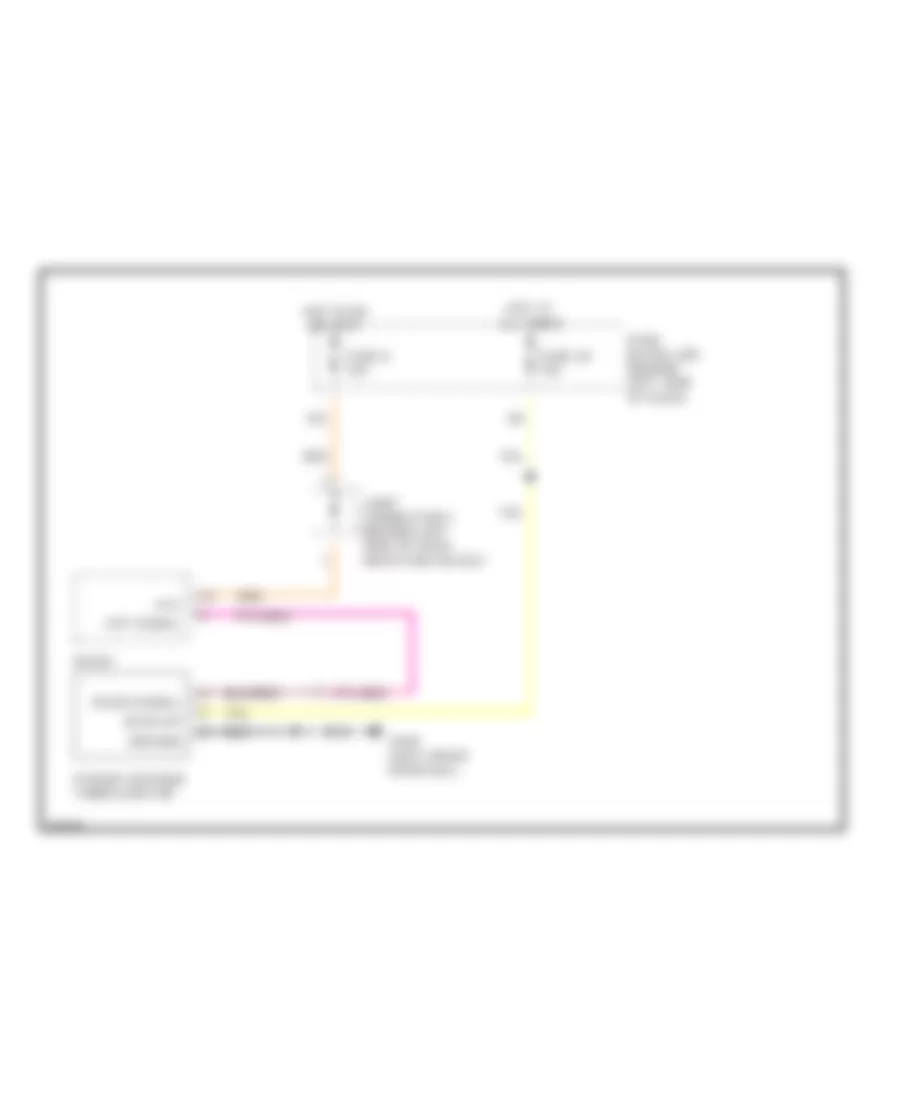
POWER ANTENNA
Power Antenna Wiring Diagram for Infiniti Q45 2000
List of elements for Power Antenna Wiring Diagram for Infiniti Q45 2000:
- 10a
- Aac
- Ant signal
- Back-up
- Fuse 28 10a
- Fuse 8 10a
- Fuse block (j/b) (behind left side of dash)
- G309 (left front door sill)
- Ground
- Hot at all times
- Hot in on or accy
- Joint connector 2 (behind left side of dash, near fuse block)
- Power antenna timer & motor
- Radio
- Radio signal
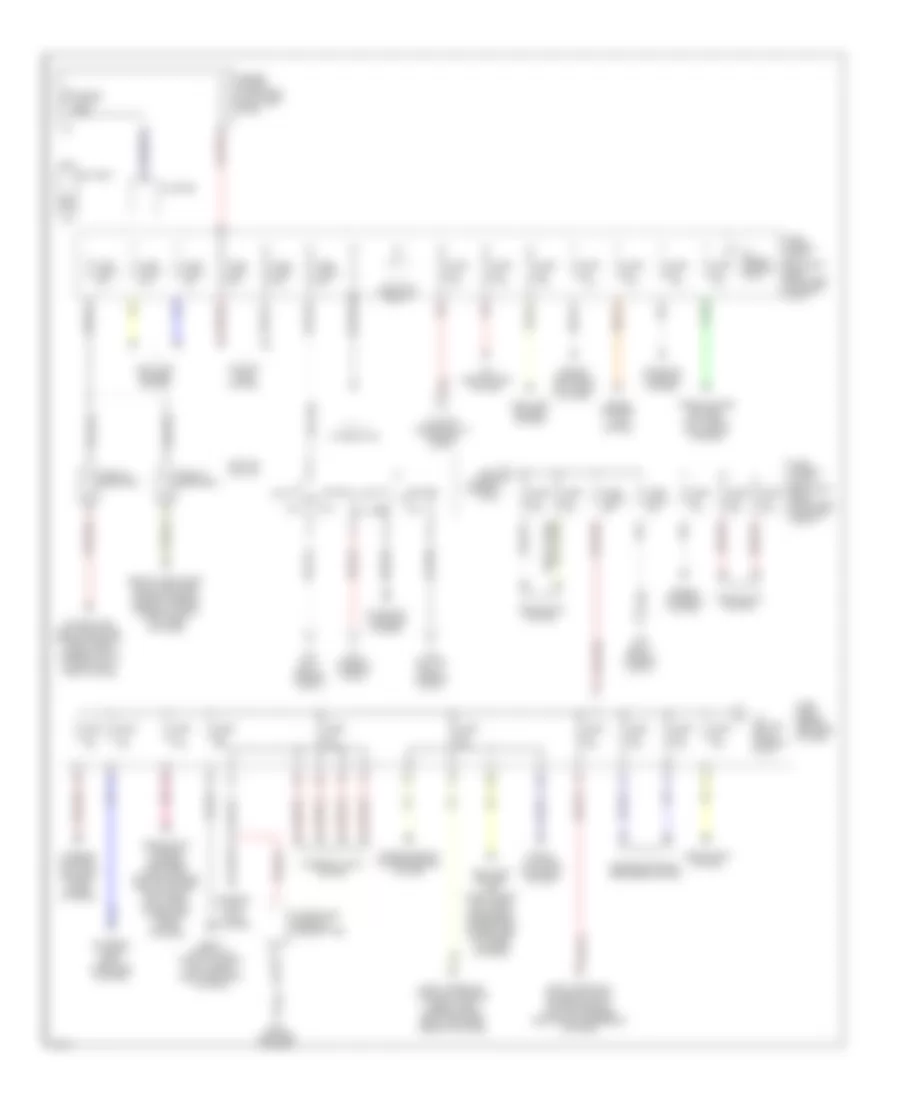
POWER DISTRIBUTION
Power Distribution Wiring Diagram (1 of 3) for Infiniti Q45 2000
List of elements for Power Distribution Wiring Diagram (1 of 3) for Infiniti Q45 2000:
- 10h
- 11b
- 12b
- 13b
- 16b
- Acc
- Air conditioning system
- Alternator
- Anti-lock brakes system
- Anti-lock brakes, air conditioning, anti-theft, electronic suspension, power tops, instrument cluster systems
- Battery
- Circuit breaker 1
- Circuit breaker 2
- Cooling fans system
- Engine controls system
- Engine controls, anti-theft systems
- Engine controls, defogger system
- Exterior lights, body computer systems
- From b fuse 64 (diagram 1 of 3)
- Fuse 10a
- Fuse 15a
- Fuse 20a
- Fuse 7.5a
- Fuse block (behind left side of dash)
- Fuse link b 80a
- Fuse link c 80a
- Fuse link f 40a
- Fuse link g 30a
- Fuse link h 40a
- Fuse link i 40a
- Fuse link j 30a
- Fuse link k 30a
- Fuse, fusible link & relay box (right front side of engine compt)
- Fusible link a 120a
- Fusible link box (at battery, on battery cable)
- G202 (left end of dash)
- Headlamp relay
- Headlights system
- Headlights, warning systems, defogger, power windows, body computer, door locks, anti-theft, power tops, interior lights systems
- Horns, cruise control, anti-theft, ivcs, sound systems
- Ignition switch
- Integrated homelink transmitter
- Interior lights system
- Interior lights, ivcs systems
- Lock
- Pnk
- Power tops, body computer, power windows, door locks, interior lights system, anti- theft system
- Red
- Red a
- Run
- Seats, door locks, body computer, power windows, memory systems, interior lights, anti-theft systems
- Shift interlock, exterior lights, cruise control, anti-lock brakes, electronic suspension systems
- Shift interlock, trunk, tailgate, fuel doors, body computer systems
- Shift interlock, warning systems, door locks, interior lights, body computer, memory systems
- Sound systems, ivcs system
- Start
- Starter
- Starting/ charging system
- To accy relay (diagram 2 of 3)
- To fuse 34 (diagram 3 of 3)
- To fuse 53 (diagram 1 of 3)
- To ignition relay (diagram 2 of 3)
- To joint connector 15 (diagram 2 of 3)
- Transmissions, power antenna system
- Trunk, tailgate, fuel door system
- Warning systems, cellular phones, sound systems
Power Distribution Wiring Diagram (2 of 3) for Infiniti Q45 2000
List of elements for Power Distribution Wiring Diagram (2 of 3) for Infiniti Q45 2000:
- (behind left side of dash) fuse block
- 10a
- 10c
- 13h
- 15b
- 17b
- 18b
- Accessory relay
- Air conditioning headlights system, wiper/ washer system, body computer, interior lights, anti-theft, memory systems
- Air conditioning system
- Anti- lock brakes system
- Anti-lock brakes, electronic suspension, electronic power steering systems
- Cellular phones system
- Cruise control system
- Defogger, headlights, warning systems, body computer, power windows, interior lights, memory systems, anti-theft, door locks, mirrors, power tops system
- Defogger, power mirror systems
- Electronic suspension system
- Engine controls system
- Engine controls, defogger, ivcs systems
- Engine controls, transmissions systems
- Exterior lights system
- From fuse 40 g (diagram 1 of 3)
- From fuse 63 a (diagram 1 of 3)
- From fuse link c (diagram 1 of 3)
- From ignition switch (diagram 1 of 3)
- Front cigarette lighter
- Front power socket
- Fuse 10a
- Fuse 15a
- Fuse 20a
- Fuse 7.5a
- Fuse block (behind left side of dash)
- G202 (left end of dash)
- G309 (left front door sill)
- G316 (right front door sill)
- Head- lights system
- Ignition relay
- Interior lights system
- Interior lights, exterior lights systems
- Interior lights, warning systems
- Joint connector 13
- Joint connector 15
- Left rear cigarette lighter
- Pnk
- Rear sunshade
- Red
- Right rear cigarette lighter
- Seats system
- Sound systems, power antenna system
- Taillight relay
- To blower relay (diagram 3 of 3)
- To fuse 2 (diagram 3 of 3)
- Transmissions, anti-lock brakes, exterior lights, cruise control, instrument cluster, anti-lock brakes, engine controls systems
- Wiper/ washer system
Power Distribution Wiring Diagram (3 of 3) for Infiniti Q45 2000
List of elements for Power Distribution Wiring Diagram (3 of 3) for Infiniti Q45 2000:
- 10d
- 12g
- 14b
- Air conditioning system
- Anti-lock brakes, engine controls systems
- Blower relay
- Body computer, memory systems
- Cooling fans system
- Engine controls system
- Engine controls, computer data lines system
- From accessory relay (diagram 2 of 3)
- From accessory relay l (diagram 2 of 3)
- From accessory relay m (diagram 2 of 3)
- From ignition relay (diagram 2 of 3)
- From ignition switch (diagram 1 of 3)
- Fuse 10a
- Fuse 15a
- Fuse 7.5a
- Fuse block (behind left side of dash)
- G202 (left end of dash)
- Headlights system
POWER DOOR LOCKS
Door Lock Wiring Diagram for Infiniti Q45 2000
List of elements for Door Lock Wiring Diagram for Infiniti Q45 2000:
- 37k
- A/d gnd
- Batt
- Body control module (bcm) (behind dash, right of steering column)
- Circuit breaker 1 (behind left kick panel)
- Circuit breaker 2 (behind left kick panel)
- Data line a1
- Data line a2
- Door lk
- Door lock
- Door unlk
- Dr door sw
- Dr unlk sw
- Driver's door control unit (inside left front door)
- Driver's door key cylinder switch
- Driver's door lock actuator
- Driver's door switch
- Front passenger's door switch
- Fuse 14 7.5a
- Fuse 28 10a
- Fuse block (behind left side of dash)
- G201 (right end of dash)
- G202 (left end of dash)
- G309 (left front door sill)
- G316 (right front door sill)
- Gnd
- Hot at all times
- Joint connector 12 (behind top center of dash, taped to harness)
- Joint connector 4 (behind upper left side of dash)
- Key switch
- Left rear door control unit (inside left rear door)
- Left rear door lock actuator
- Lock
- Lock sw
- Memory systems
- Passenger's door control unit (inside right front door)
- Passenger's door key cylinder switch
- Passenger's door lock actuator
- Pnk
- Ps door sw
- Ps unlk sw
- Red
- Right rear door control unit (inside right rear door)
- Right rear door lock actuator
- Seats systems
- Unlk sens
- Unlock
Keyless Entry Wiring Diagram for Infiniti Q45 2000
List of elements for Keyless Entry Wiring Diagram for Infiniti Q45 2000:
- (left front door sill) g309
- (right end of dash) g201
- 37k
- 44r
- A/d gnd
- Acc
- Ant
- Anti- theft system
- Batt
- Body control module (bcm) (behind dash, right of steering column)
- Circuit breaker 1 (behind left kick panel)
- Circuit breaker 2 (behind left kick panel)
- Data line a1
- Data line a2
- Door lk
- Door lock
- Door locks system
- Door unlk
- Dr door sw
- Driver's door control unit (inside left front door)
- Driver's door switch
- Exterior lights system
- Front passenger's door switch
- Fuse 10a
- Fuse 7.5a
- Fuse block (behind left side of dash)
- G201 (right end of dash)
- G202 (left end of dash)
- G309 (left front door sill)
- G316 (right front door sill)
- Gnd
- Hazard
- Head- lights system
- Hot at all times
- Hot in acc or on
- Joint connector 12 (behind top center of dash, taped to harness)
- Joint connector 4 (behind upper left side of dash)
- Key switch
- Left rear door control unit (inside left rear door)
- Left rear door switch
- Lock sw
- Multi-remote control relay (in right front corner of luggage compt)
- Nca
- Passenger's door control unit (inside right front door)
- Pnk
- Ps door sw
- Red
- Right rear door control unit (inside right rear door)
- Right rear door switch
- Rl door sw
- Rr door sw
- Theft relay
- Theft warning horn relay (in right front corner of luggage compt)
- Theft warning lamp relay (in fuse block)
- Trunk opener
- Trunk, tailgate, & fuel doors system
- Unlk sens
- Unlock sw
- Window antenna
POWER MIRRORS
Auto Anti-dazzling Inside Mirror for Infiniti Q45 2000
List of elements for Auto Anti-dazzling Inside Mirror for Infiniti Q45 2000:
- 18b
- Auto anti- dazzling inside mirror
- Fuse 32 7.5a
- Fuse block (behind left side of dash)
- G202 (left end of dash)
- Ground
- Hot in on or start
- Interior lights system
- Joint connector 3 (behind left side of dash, near fuse block)
- Red
Power Mirrors Wiring Diagram for Infiniti Q45 2000
List of elements for Power Mirrors Wiring Diagram for Infiniti Q45 2000:
- Door mirror remote control switch
- Driver's side door mirror actuator
- Fuse 9 7.5a
- Fuse block (behind left side of dash)
- G202 (left end of dash)
- Hot in on or accy
- Passenger's side door mirror actuator
POWER SEATS
Heated Seats Wiring Diagram for Infiniti Q45 2000
List of elements for Heated Seats Wiring Diagram for Infiniti Q45 2000:
- Driver's
- Driver's heated seat switch
- Driver's seat back heater
- Fuse 21 10a
- Fuse block (behind left side of dash)
- G309 (left front door sill)
- G316 (right front door sill)
- High
- Hot in on or start
- Low
- Passenger's heated seat switch
- Passenger's seat back heater
- Passenger's seat cushion heater
- Red
- Seat cushion heater
Passenger Power Seat Wiring Diagram for Infiniti Q45 2000
List of elements for Passenger Power Seat Wiring Diagram for Infiniti Q45 2000:
- Circuit breaker 2 (behind left kick panel)
- Front lift
- Front limit switch
- G316 (right front door sill)
- Hot at all times
- Joint connector 12 (behind top center of dash)
- Lumbar
- Lumbar support motor
- Nca
- Passenger's side lifting motor (bottom of seat frame)
- Passenger's side power seat switch
- Passenger's side reclining motor
- Passenger's side sliding motor
- Pnk
- Rear lift
- Rear limit switch
- Recline
- Red
- Slide switch
- Switch
POWER TOP/SUNROOF
Power Top/Sunroof Wiring Diagrams for Infiniti Q45 2000
List of elements for Power Top/Sunroof Wiring Diagrams for Infiniti Q45 2000:
- 16b
- Auto open
- Auto open relay 1
- Auto open relay 2
- Body control module (bcm) (behind dash, right of steering column)
- Circuit breaker 1 (behind left kick panel)
- Close
- Down
- Down/open relay
- Full closed
- Full tilt-up
- Fuse 28 10a
- Fuse block (behind left side of dash)
- Hot at all times
- Joint connector 1 (behind left side of dash)
- Joint connector 12 (behind top center of dash)
- Nca
- Open
- Red
- Slide switch
- Sun roof motor assembly
- Sun roof relay (in fuse block)
- Sun roof switch
- Tilt switch
- Timer
- Up/close relay
POWER WINDOWS
Power Window Wiring Diagram for Infiniti Q45 2000
List of elements for Power Window Wiring Diagram for Infiniti Q45 2000:
- (left end of dash)
- 18b
- A/d ground
- Accessory
- Battery
- Body control module (bcm) (behind dash, right of steering column)
- Circuit breaker 1 (behind left kick panel)
- Circuit breaker 2 (behind left kick panel)
- Data line a1
- Data line a2
- Driver's door control unit (inside left front door)
- Driver's side front power window regulator
- Fuse 14 7.5a
- Fuse 23 7.5a
- Fuse 32 7.5a
- Fuse 34 7.5a
- Fuse block (behind left side of dash)
- G201 (right end of dash)
- G202
- G202 (left end of dash)
- G309 (left front door sill)
- G316 (right front door sill)
- Ground
- Hot at all times
- Hot in accy or on
- Hot in on or start
- Hot in start
- Ignition
- Joint connector 12 (behind top center of dash, taped to harness)
- Joint connector 3 (behind left side of dash, near fuse box)
- Joint connector 4 (behind upper left side of dash)
- Left rear door control unit (inside left rear door)
- Left rear power window regulator
- P/w down
- P/w up
- Passenger's door control unit (inside right front door)
- Passenger's front power window regulator
- Pnk
- Right rear door control unit (inside right rear door)
- Right rear power window regulator
- Start
RADIO
Radio Wiring Diagrams for Infiniti Q45 2000
List of elements for Radio Wiring Diagrams for Infiniti Q45 2000:
-
-
-
- ground acc
- (behind left kick panel) joint conn 9
- (right rear corner of luggage compt) cd auto changer
- 10a
- Acc
- Amp on sig
- Antenna ctrl
- Audio amplifier relay (in right front corner of luggage compt)
- Back up
- Bat
- Battery
- Bose speaker amplifier (at center front of luggage compt)
- Cd lh in (+)
- Cd lh in (-)
- Cd rh in (+)
- Cd rh in (-)
- Data ground
- Fr lh (+) amp
- Fr lh (-) amp
- Fr lh in (+)
- Fr lh in (-)
- Fr lh out (+)
- Fr lh out (-)
- Fr rh (+) amp
- Fr rh (-) amp
- Fr rh in (+)
- Fr rh in (-)
- Fr rh out (+)
- Fr rh out (-)
- Fuse 12 10a
- Fuse 58 15a
- Fuse 8 10a
- Fuse block (j/b) (behind left side of dash)
- Fuse, fusible link & relay box (right front side of engine compt)
- G202 (left end of dash)
- G401 (right front side of trunk)
- G407 (center rear of trunk)
- Ground
- Horns system
- Hot at all times
- Hot in on or acc
- Illum
- Interior lights system
- Joint conn (below radio)
- Joint connector 2 (behind left side of dash, near fuse block)
- Joint connector 7 (behind left kick panel)
- Left front door speaker
- Left rear door speaker
- Left rear speaker
- Left tweeter
- Lh (+) out
- Lh (-) out
- Mode
- Nca
- Nca antenna in
- Nca antenna in
- Pnk
- Power
- Power antenna system
- Power on sig
- Pulse
- Radio
- Red
- Req
- Rh (+) out
- Rh (-) out
- Right front door speaker
- Right rear door speaker
- Right rear speaker
- Right tweeter
- Rod antenna
- Rr lh (+) amp
- Rr lh (-) amp
- Rr lh in (+)
- Rr lh in (-)
- Rr lh out (+)
- Rr lh out (-)
- Rr rh (+) amp
- Rr rh (-) amp
- Rr rh in (-)
- Rr rh out (+)
- Rr rh out (-)
- Rxd
- Seek/aps up
- Spiral cable (steering wheel)
- Steering wheel receiver control switch
- Steering wheel switch
- Txd
- Vol down
- Vol up
- Warning systems
- Window antenna
SHIFT INTERLOCKS
Shift Interlock Wiring Diagram for Infiniti Q45 2000
List of elements for Shift Interlock Wiring Diagram for Infiniti Q45 2000:
- (front of left front fender) g100
- A/t device (under console, near base of selector lever)
- Battery
- Detent sw
- Fuse 17 10a
- Fuse 26 20a
- Fuse 28 10a
- Fuse 37 15a
- Fuse block (j/b) (behind left side of dash)
- G201 (right end of dash)
- G202 (left end of dash)
- Ground
- Hot at all times
- Hot in on or start
- Ignition
- Joint con- nector 1 (behind left of dash, near fuse block)
- Joint con- nector 11 (top center of dash, taped to harness)
- Key lk sol
- Key switch & key lock solenoid (ignition switch assembly)
- Red
- Shift lk sol
- Shift lock control unit (behind dash, left of steering column)
- Stoplamp switch (pedal bracket)
STARTING/CHARGING
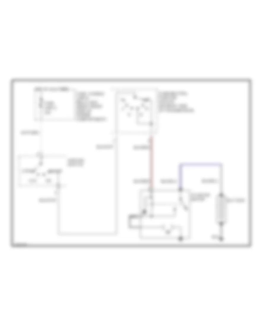
Charging Wiring Diagram for Infiniti Q45 2000
List of elements for Charging Wiring Diagram for Infiniti Q45 2000:
- 120a
- 68n
- Alternator
- Charge warning indicator
- Combination meter
- Fuse 4 7.5a
- Fuse 62 7.5a
- Fuse block (j/b) (behind left side of dash)
- Fuse link a
- Fuse, fusible link & relay box (right front of engine compartment)
- G118 (right front frame rail)
- Hot at all times
- Hot in on or start
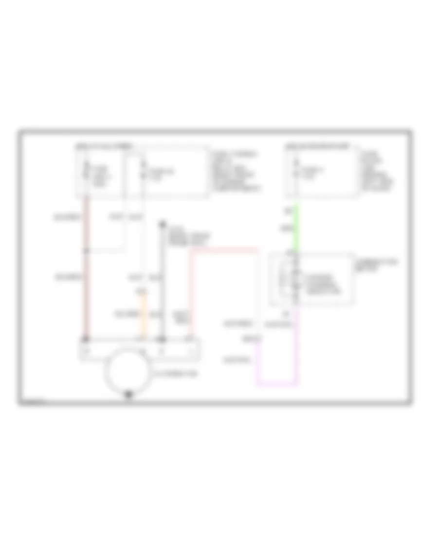
Starting Wiring Diagram for Infiniti Q45 2000
List of elements for Starting Wiring Diagram for Infiniti Q45 2000:
- 30a
- Acc
- Battery
- Fuse link g
- Fuse, fusible link & relay box (right front side of engine compartment)
- Hot at all times
- Ignition switch
- Lock
- Nca
- Park/neutral position switch (on right side of transmission)
- Start
- Starter motor
SUPPLEMENTAL RESTRAINTS
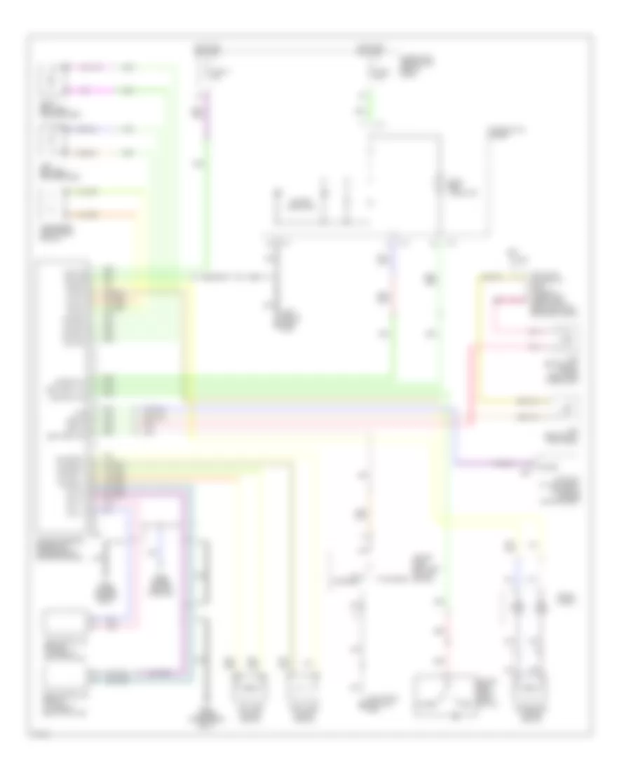
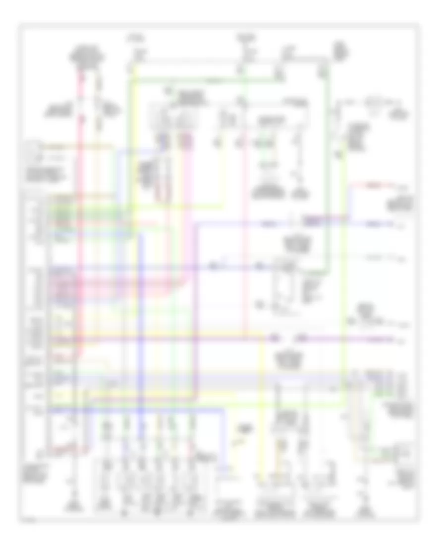
Supplemental Restraint Wiring Diagram for Infiniti Q45 2000
List of elements for Supplemental Restraint Wiring Diagram for Infiniti Q45 2000:
- (left front door sill) g309
- (left side of dash) g202
- Air bag
- Air bag diagnosis sensor unit (under rear of center console)
- Air bag indicator
- Air bag w/l
- B55
- B68
- Closed
- Combination meter
- Data link connector (dlc) (partial) (under left side of dash, near hood lock release handle)
- Door switch
- Driver side air bag module
- Driver side front door switch
- Driver side seat belt buckle switch
- Fastened
- Fuse 17 10a
- Fuse 4 7.5a
- Fuse block (behind left side of dash)
- G300 (under driver's seat)
- G301 (under passenger's seat)
- G302 (under center console)
- Ground
- Hot in on or start
- Ignition
- Ivcs
- Ivcs unit (at left front corner of luggage compartment)
- J/c 2 (behind left side of dash, near fuse block)
- J/c 8 (behind left kick panel)
- Left satellite sensor (at base of left "b" pillar)
- Left seat belt pretensioner
- Left side air bag module
- N13
- N14
- Nca
- Open
- Passenger side air bag module
- Pnk
- Red
- Right satellite sensor (at base of right "b" pillar)
- Right seat belt pretensioner
- Right side air bag module
- Sat l +
- Sat l -
- Sat r +
- Sat r -
- Seat belt indicator
- Seat belt sw
- Seat belt w/l
- Spiral cable
- Sq as +
- Sq as -
- Sq dr +
- Sq dr -
- Sq pas +
- Sq pas -
- Sq pdr +
- Sq pdr -
- Sq side l +
- Sq side l -
- Sq side r +
- Sq side r -
- Sss rx
- Sss tx
- Un- fastened
TRANSMISSION
A/T Wiring Diagram for Infiniti Q45 2000
List of elements for A/T Wiring Diagram for Infiniti Q45 2000:
- (behind left kick panel) j/c 16
- (behind left kick panel) j/c 8
- (right side of trnsmission) park/neutral position switch
- (under left side of dash, beside hood lock release handle) data link connector
- 1-sw
- 13h
- 15b
- 2-sw
- A/t device (overdrive control switch) (below center console)
- A/t fluid temp sensor
- Abs/tcs control unit (behind right side of dash)
- All times
- Ascd
- Ascd control unit (behind dash, left of steering column)
- At1
- At2
- Automatic transaxle at3
- Avcc
- Bus-b
- Closed throttle
- Combination meter
- Cruise control
- D-sw
- Diodes (under carpet, near driver's door sill)
- Dropping resistor (at right side of eng compt, forward of strut tower)
- Engine control module (ecm) (behind right kick panel)
- Full sw
- Fuse 10a
- Fuse 7.5a
- Fuse block (behind side of dash)
- G125 (front of engine)
- G201 (right end of dash)
- G202 (left end of dash)
- Grd
- Grd-a
- Grd-c
- Hot at
- Hot in on or start
- Idle
- Idle sw
- J/c 11
- J/c 2 (behind left side of dash, near fuse box)
- J/c 6
- J/c 6 (behind upper right side of dash, taped to harness)
- J/c 8 (behind left kick panel)
- Lan
- Line press sol valve
- Mem bu
- N-sw
- Nca
- O/d cntl
- O/d ind
- O/d off ind
- O/t sens
- Over- run clutch sol
- Ovr/c s
- Pl dty s
- Pnk
- R-sw
- Red
- Revolution sensor (left rear side of transmission)
- Sens bat
- Sens grd
- Shift sol valve a
- Shift sol valve b
- Sp sens
- Ssa
- Ssb
- Sss in
- Sss out
- Tacho
- Tcc sol
- Tcc sol valve
- Throttle position sensor (on throttle body)
- Throttle position switch (on throttle body)
- Transmission control module (tcm) (behind left kick panel)
- Ts in
- Turbine
- Turbine revolution sensor (top of transmission, behind bellhousing)
- Tv01
- Tvoo
- Unified meter control unit
- V ign
- Vehicle speed sensor (on transmission rear extension)
- Vsp
- Wot
TRUNK, TAILGATE, FUEL DOOR
Trunk & Fuel Door Release Wiring Diagram for Infiniti Q45 2000
List of elements for Trunk & Fuel Door Release Wiring Diagram for Infiniti Q45 2000:
- Body control module (bcm) (behind dash, right of steering column)
- Fuel lid opener actuator (right side of luggage compt)
- Fuel lid opener relay (right front corner of luggage compt)
- Fuel lid opener switch
- Fuse 26 20a
- Fuse block (behind left side of dash)
- G202 (left end of dash)
- G316 (right front door sill)
- Hot at all times
- Trunk lid & fuel lid opener switch
- Trunk lid opener actuator (center rear of deck lid)
- Trunk lid opener cancel switch
- Trunk lid opener switch
- Trunk opener
Trunk Pull-Down Wiring Diagram for Infiniti Q45 2000
List of elements for Trunk Pull-Down Wiring Diagram for Infiniti Q45 2000:
- 10h
- Fuse 27 10a
- Fuse 28 10a
- Fuse block (behind left side of dash)
- G401 (right front side of trunk)
- G405 (right rear side of trunk)
- Hot at all times
- Off
- Stop switch
- Striker switch
- Trunk closure control
- Trunk closure control unit (at center rear of luggage compt)
- Trunk closure motor
- Trunk room lamp
- Trunk room lamp switch
WARNING SYSTEMS
Warning System Wiring Diagrams for Infiniti Q45 2000
List of elements for Warning System Wiring Diagrams for Infiniti Q45 2000:
- 18b
- 1st
- 2nd
- 37k
- Auto
- Body control module (behind dash, right of steering column)
- Chime
- Comb- ination switch (lighting switch)
- Door sw
- Driver's door switch
- Driver's seat belt switch (driver's buckle)
- Exterior lights system
- Fuse 12 10a
- Fuse 22 7.5a
- Fuse 28 10a
- Fuse 32 7.5a
- Fuse block (j/b) (behind left side of dash)
- G100 (front of left front fender)
- G201 (right end of dash)
- G309 (left front door sill)
- Gnd
- Hot at all times
- Hot in on or start
- Hot in park or head
- Ignition
- Joint connector 2 (behind left side of dash, near fuse block)
- Joint connector 3 (behind left side of dash, near fuse block)
- Joint connector 7 (behind left kick panel)
- Key sw
- Key switch (ignition switch assembly)
- Light sw
- Nca
- Off
- Red
- Seat blt sw
- Tail/l rly
- Warning chime (behind instrument cluster)
WIPER/WASHER
Wiper/Washer Wiring Diagram for Infiniti Q45 2000
List of elements for Wiper/Washer Wiring Diagram for Infiniti Q45 2000:
- Accessory
- Body control module (behind dash, right of steering column)
- Front fender)
- Front wiper motor (right side of firewall)
- Front wiper relay (fuse, fusible link & relay box)
- Front wiper switch
- Fuse 11 20a
- Fuse 23 7.5a
- Fuse block (behind left side of dash)
- G101 (front of right front fender)
- Hot in run or accy
- Int
- Int (vr)
- Lo hi
- Off
- Pnk
- Red
- Wash
- Washer motor (in reservoir)
- Wiper amp
- Wiper sw int
- Wiper sw wsh
- Wipr autostop