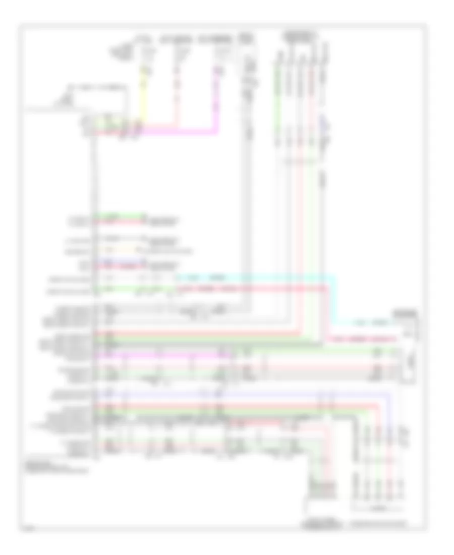
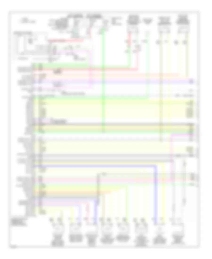
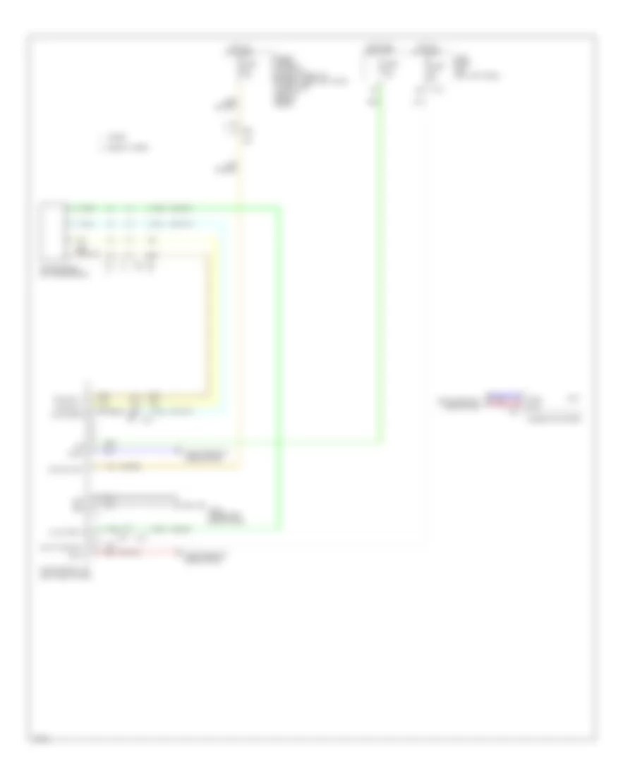
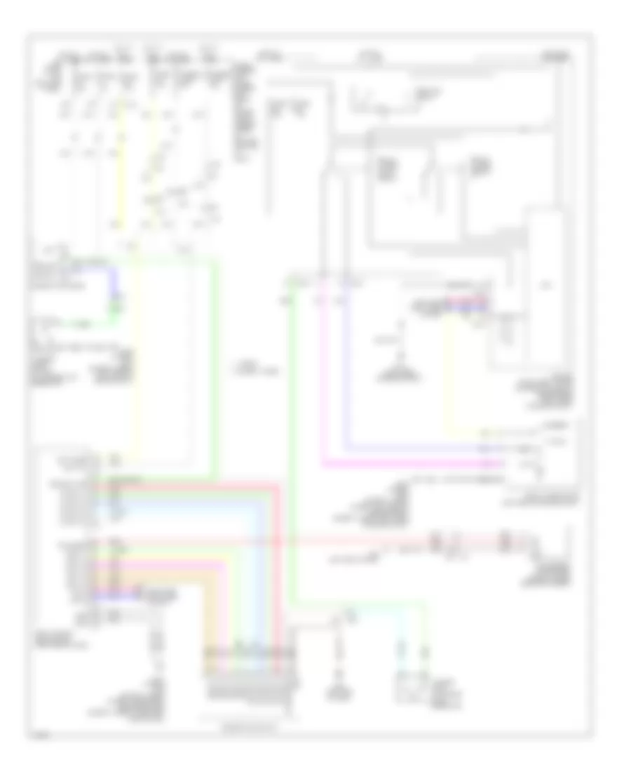
AIR CONDITIONING
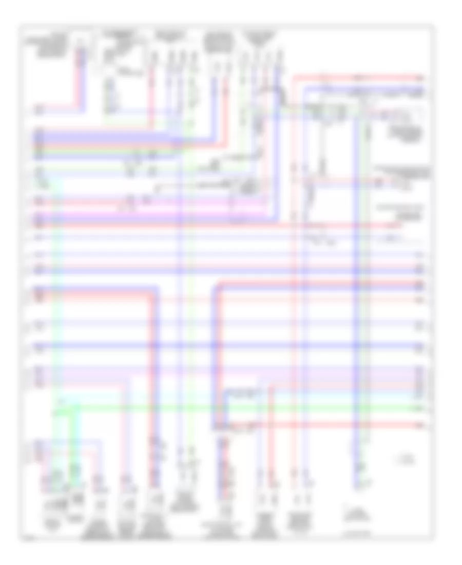
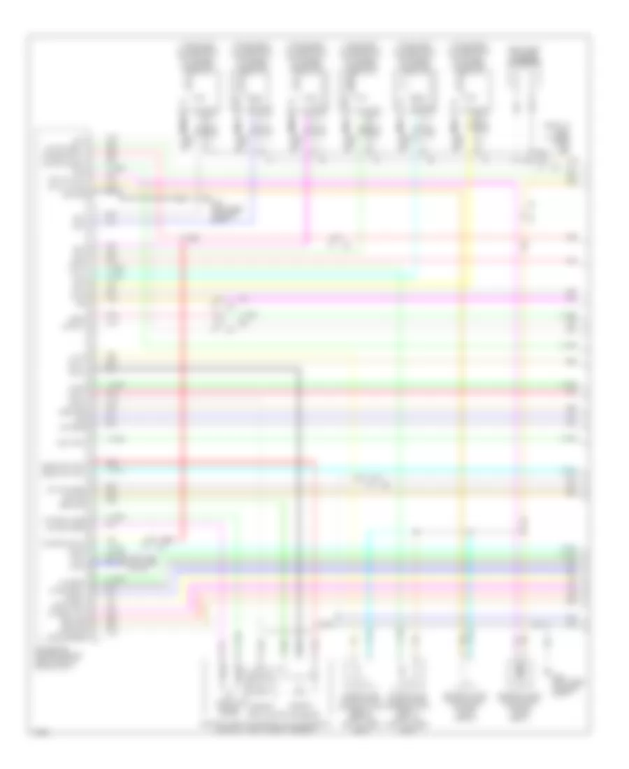
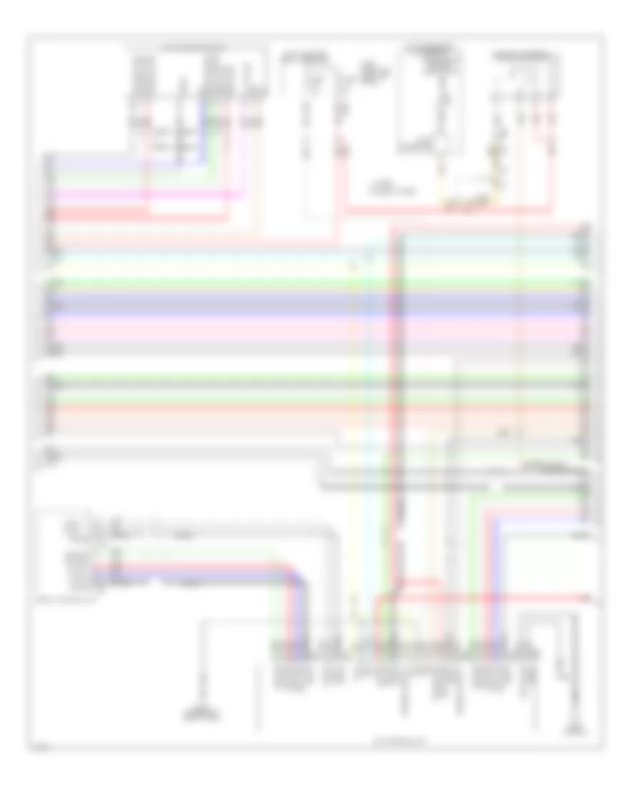
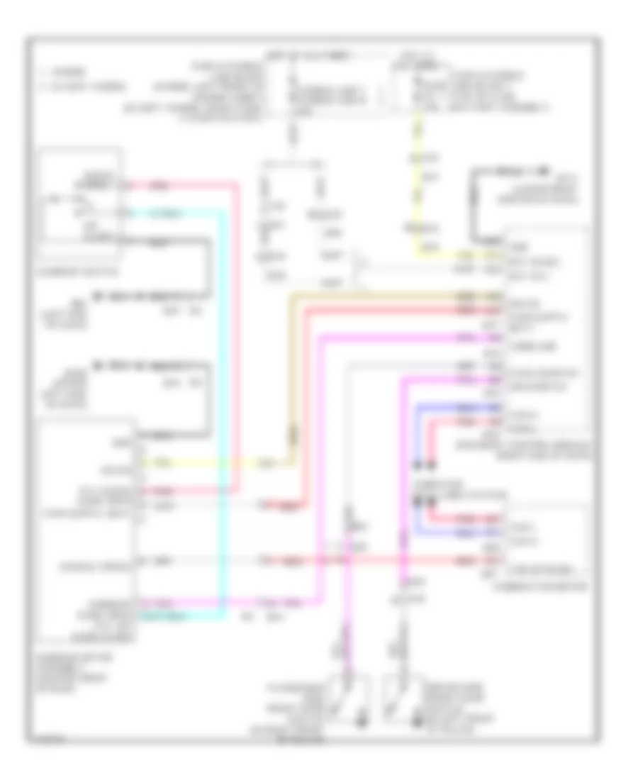
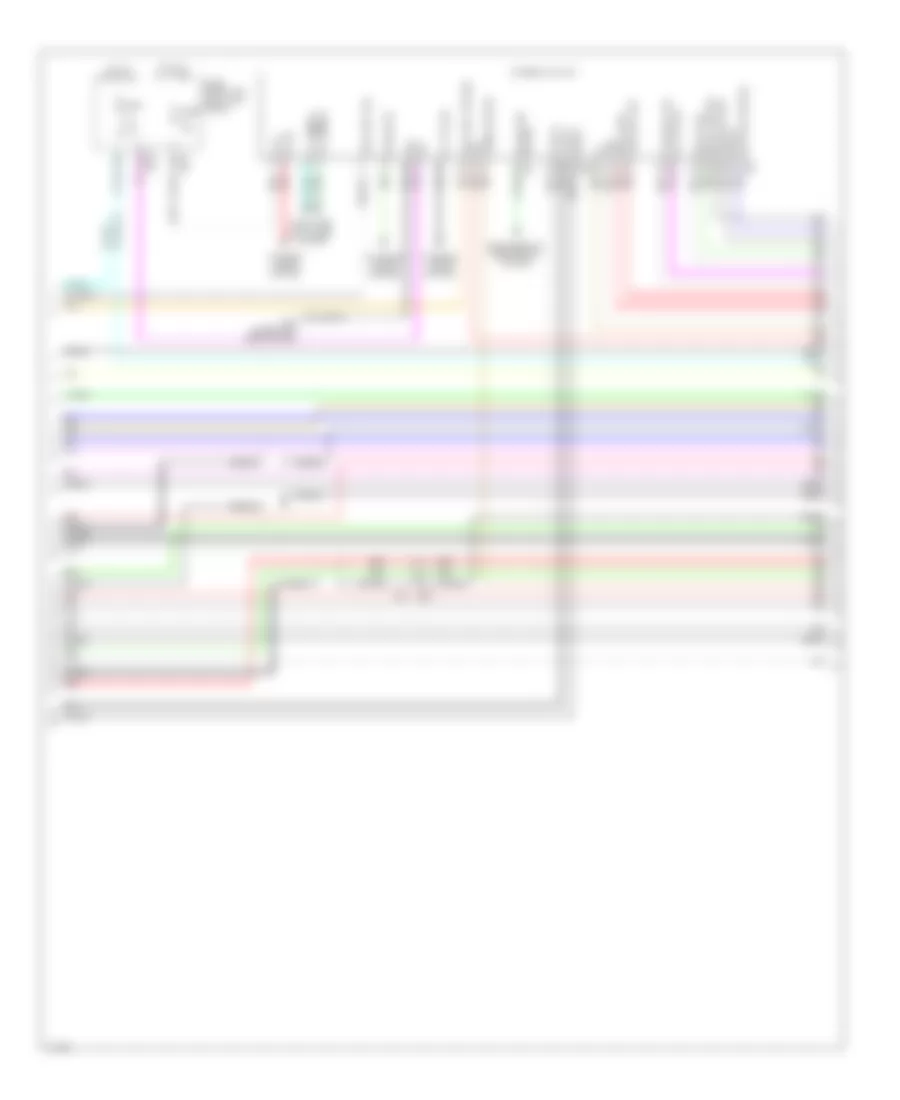
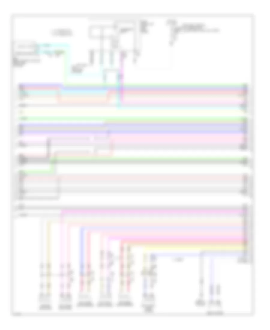
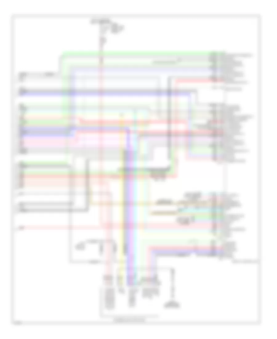
Automatic A/C Wiring Diagram (1 of 3) for Infiniti Q50 Hybrid Sport 2014

List of elements for Automatic A/C Wiring Diagram (1 of 3) for Infiniti Q50 Hybrid Sport 2014:
- (right end of dash) bcm (body control module)
- (upper left side of dash) m108
- 20c m133
- 30c
- 31c
- 33c
- 39c
- 7e e64
- A/c auto amplifier (behind integral switch)
- Ambient sens
- Ambient sensor (behind center of front grille)
- Bat
- Blower
- Blower motor cont
- Blower relay
- Can-h
- Can-l
- Computer data lines system
- Door motor pwr sply
- E14
- E25
- E25 m40
- E47 m39
- E65 11f
- E76
- E76 e14
- Ecv cont
- Except hybrid
- Exh gas/out odor dtct sens
- Fuse 10a
- Fuse 15a
- Fuse 5a
- Fuse block (j/b) (left kick panel)
- Gnd
- Heat strg whl rly cont
- Heater pump cont
- Hot at all times
- Hot w/ accessory relay energized
- Hot w/ ignition relay energized
- Hybrid
- Ign sw acc
- Ign sw on
- In-vehicle sens
- In-vehicle sensor (lower left center of dash)
- Intake sens
- Intake sensor (on hvac evaporator assembly)
- Ionizer cont
- Lin
- M108 (except hybrid) (upper left side of dash)
- M111 (hybrid) (lower right center of dash)
- M131 2a
- M133 19c
- M14
- M40
- M88
- M89
- M90
- M93 (left end of dash)
- Pnk
- Red
- Rly cont
- Seat htr sens gnd1
- Seat htr sens gnd2
- Seat htr sens1
- Seat htr sens2
- Seat htr1
- Seat htr2
- Seats system
- Sens gnd
- Sunload sens
- Sunload sensor (top left side of dash)
- Tan
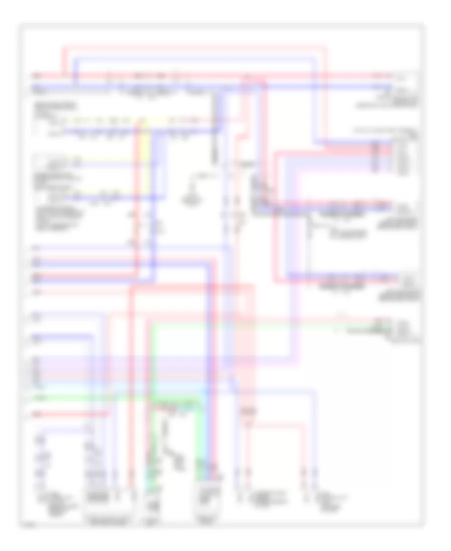
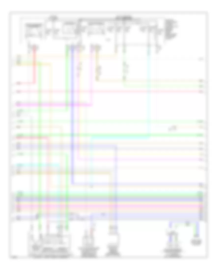
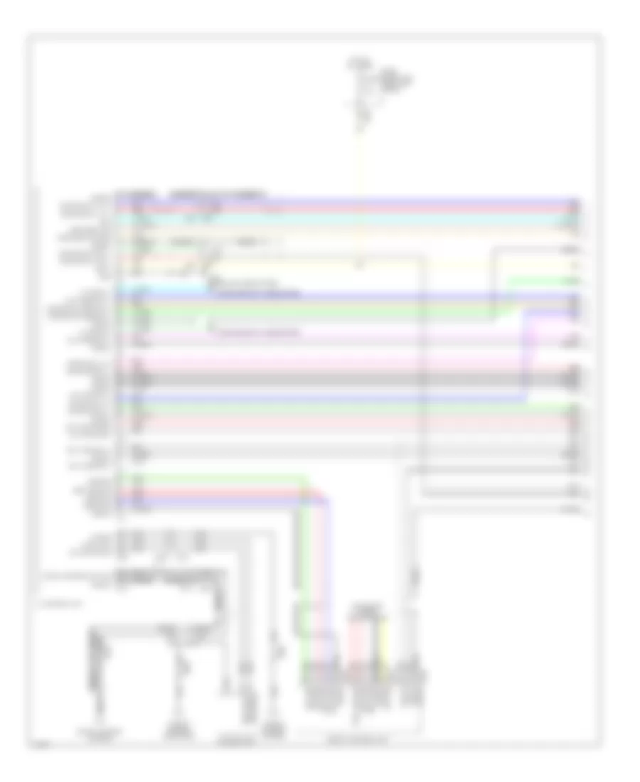
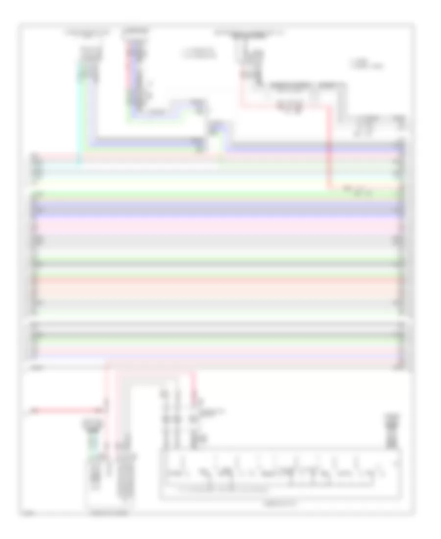
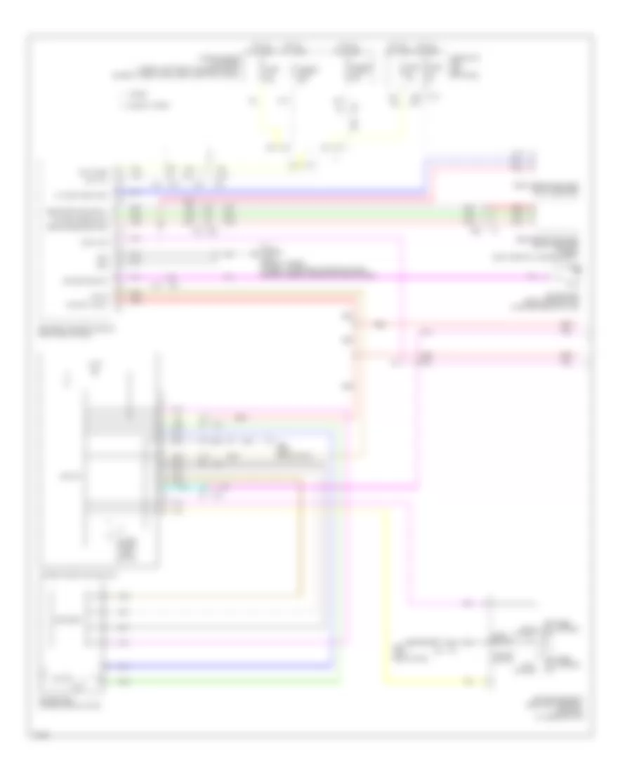
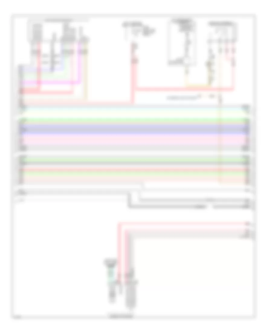
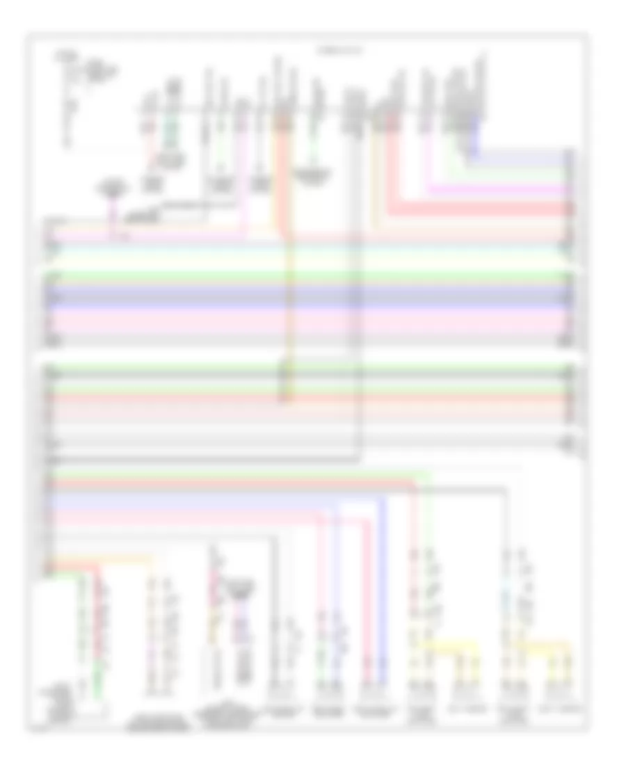
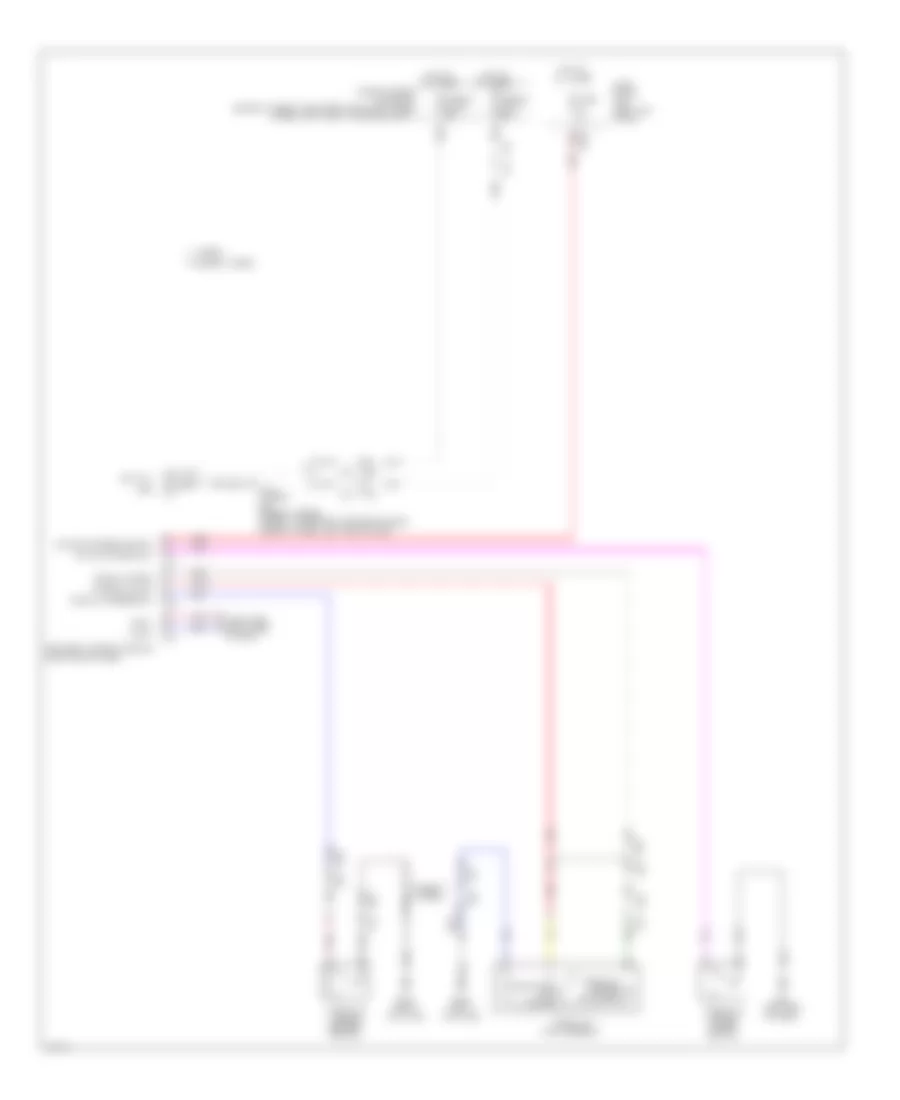
Automatic A/C Wiring Diagram (2 of 3) for Infiniti Q50 Hybrid Sport 2014
List of elements for Automatic A/C Wiring Diagram (2 of 3) for Infiniti Q50 Hybrid Sport 2014:
- (bottom center front of engine compt) (hybrid) heater pump
- Amp
- Amplifier
- Aqs power
- Aqs s gnd
- Aqs s output
- Blower motor (under right side of dash)
- E138 (left rear of engine compt)
- E76 e14
- Electric compressor (hybrid) (left front of engine compt)
- Except hybrid
- Exhaust gas/outside odor detecting sensor (w/ accs) (behind center of front grille)
- F11
- F61
- Gnd
- Hybrid
- Ign
- Intake door motor (upper right side of hvac unit)
- Ion on off
- Ionizer (w/ accs) (upper center of dash)
- Left air mix door motor (left side of hvac unit)
- Li-ion battery controller (hybrid) (left side of li-ion battery assembly)
- M128
- M93 (hybrid) m108 (except hybrid) (hybrid: left end of dash) (except hybrid: upper left side of dash)
- M93 (left end of dash)
- Mode door motor (upper right side of hvac blower housing)
- Nca
- Pnk
- Red
- Right air mix door motor (right side of hvac unit)
- Tan
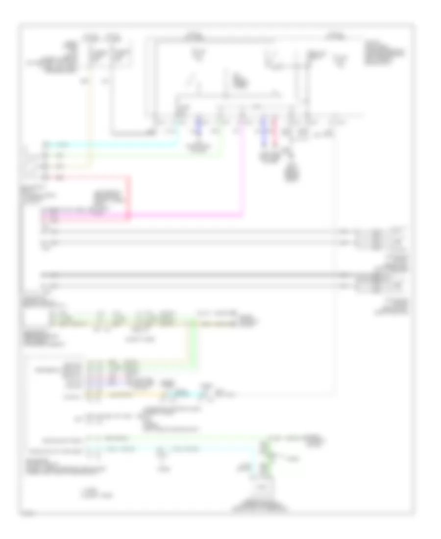
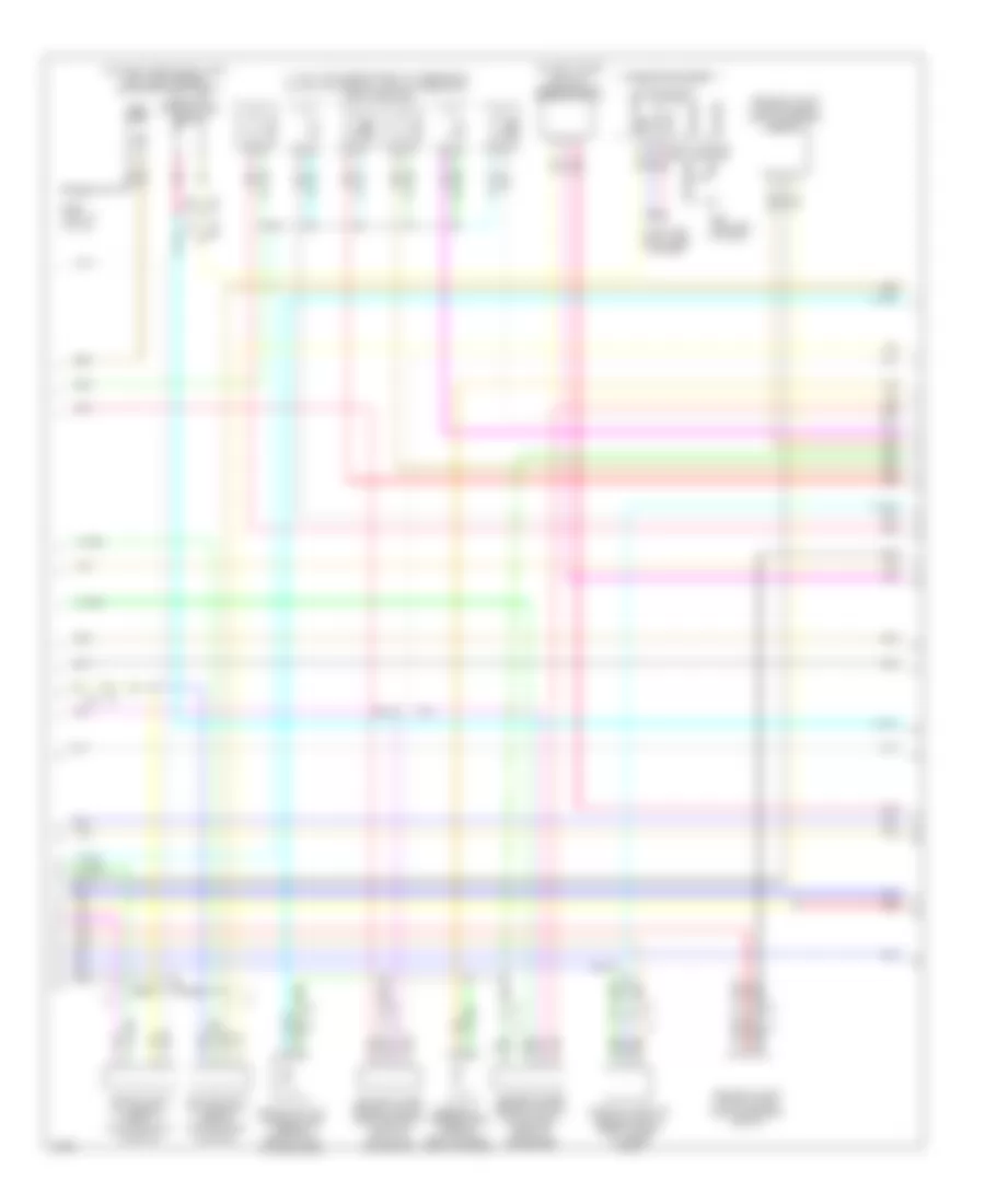
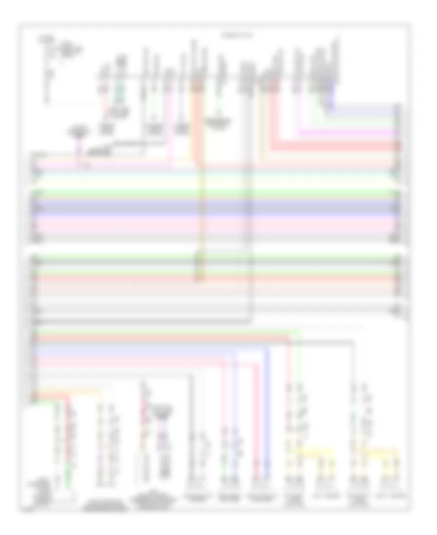
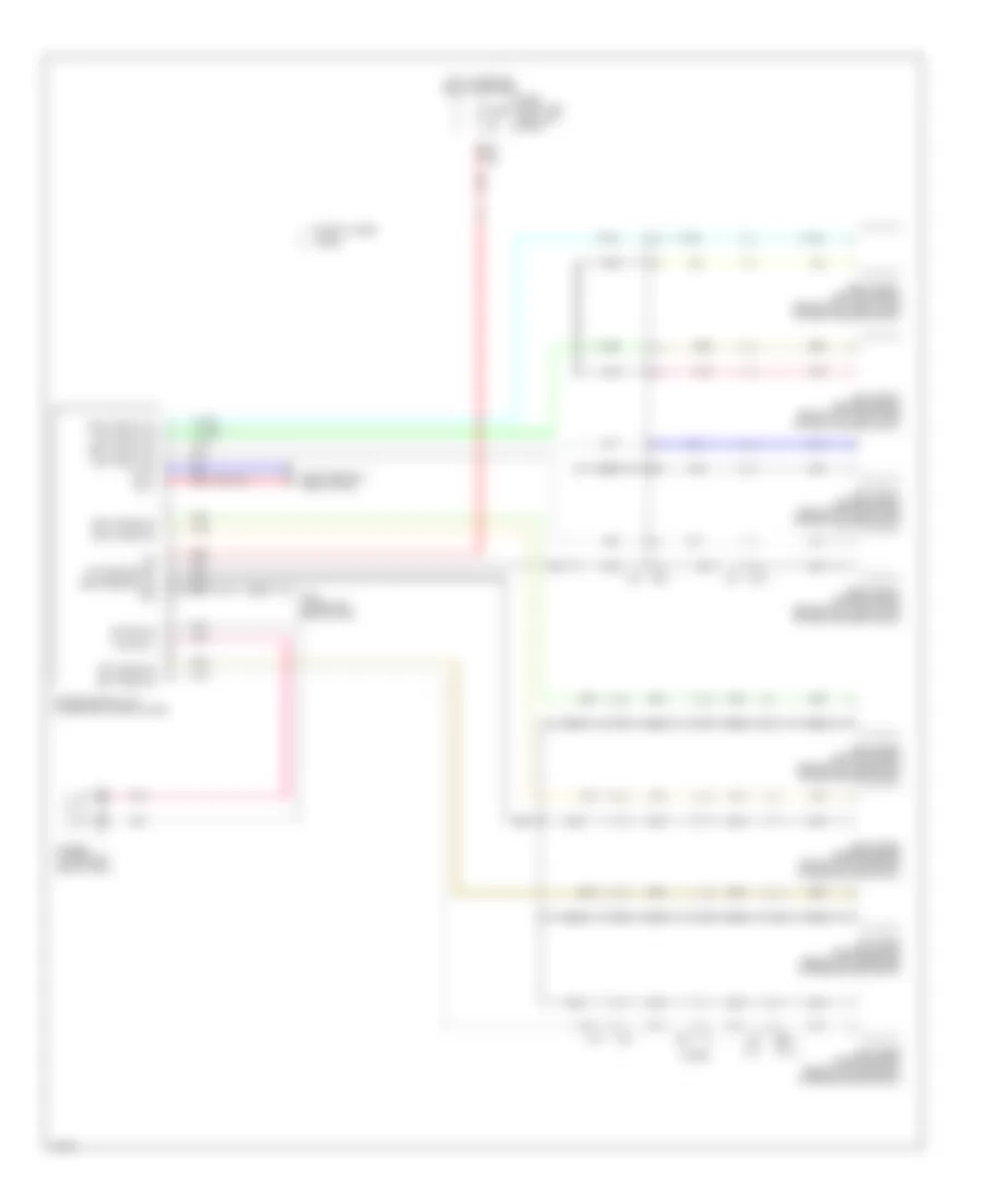
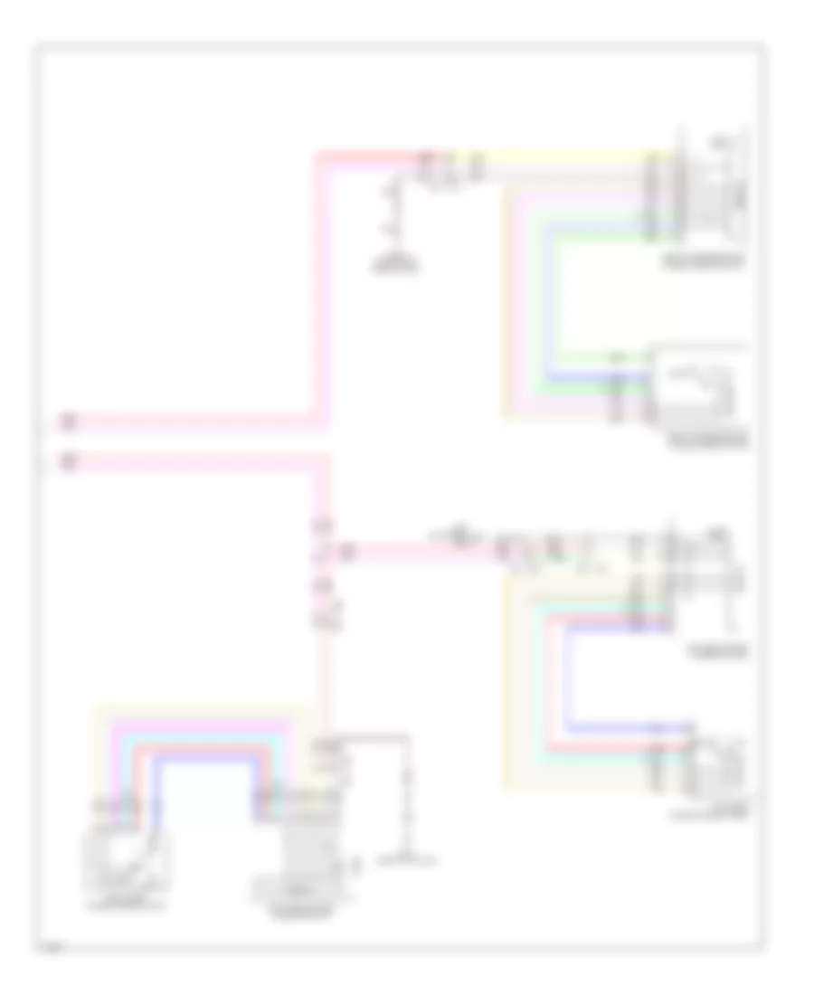
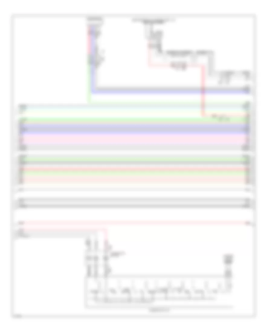
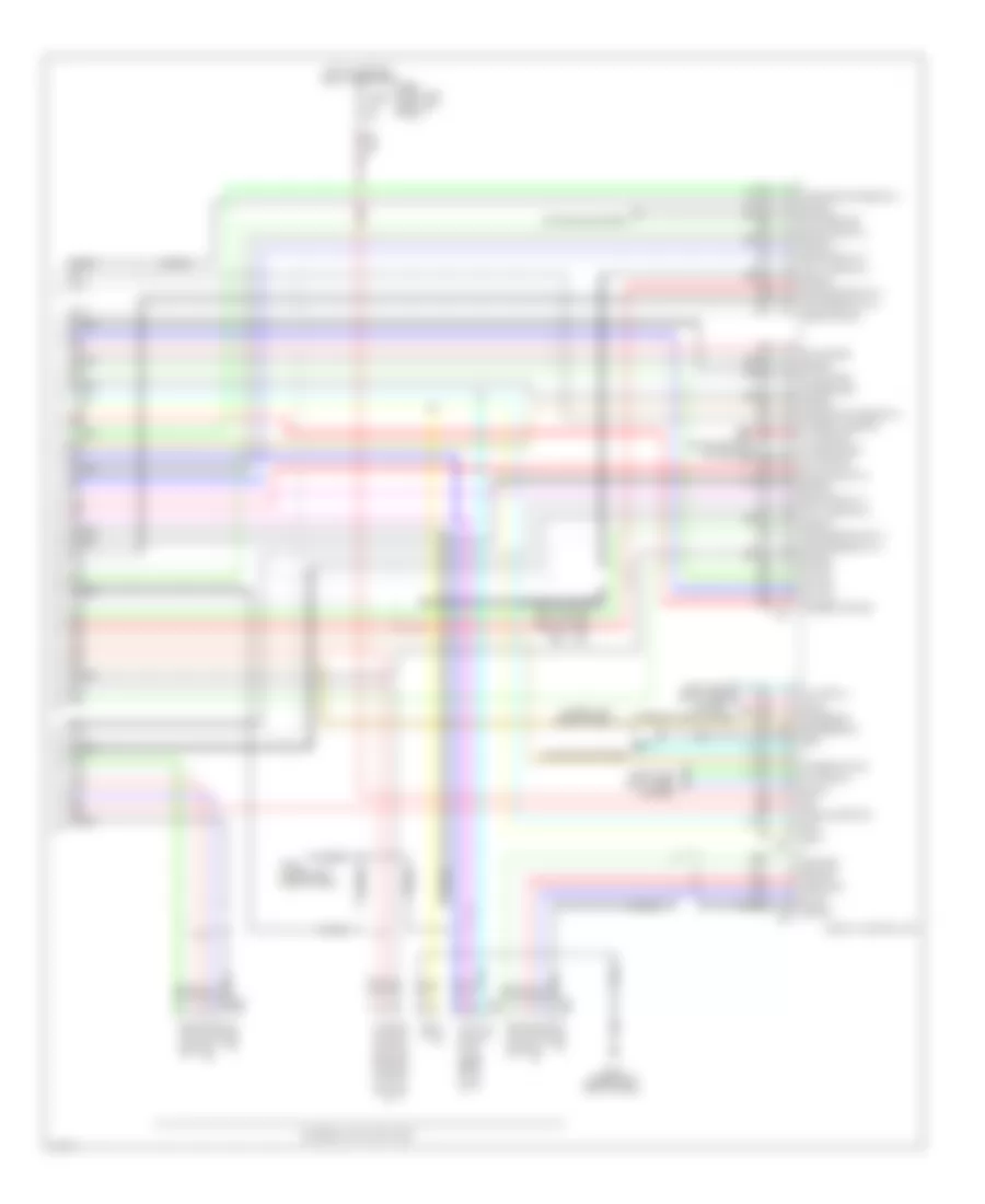
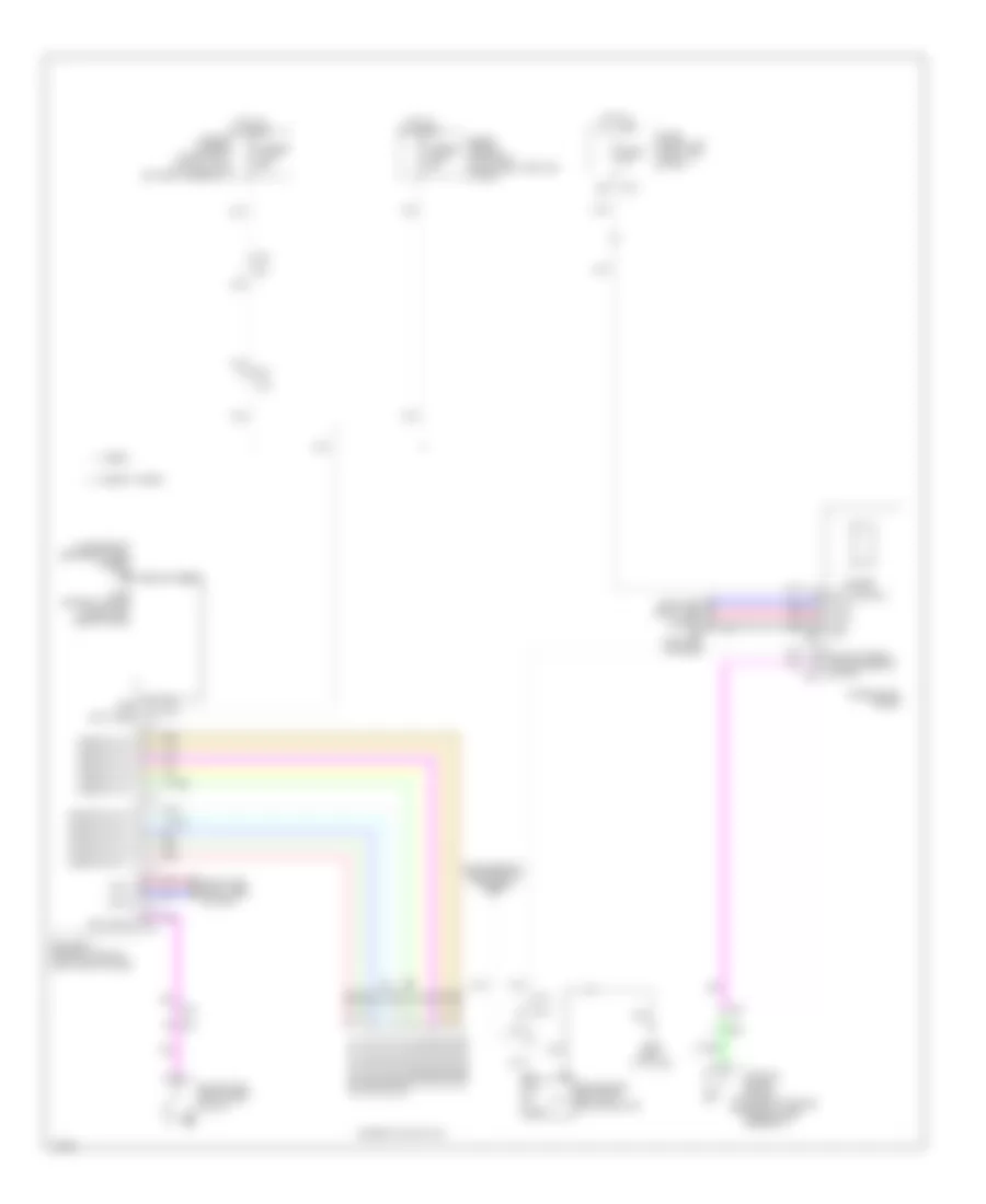
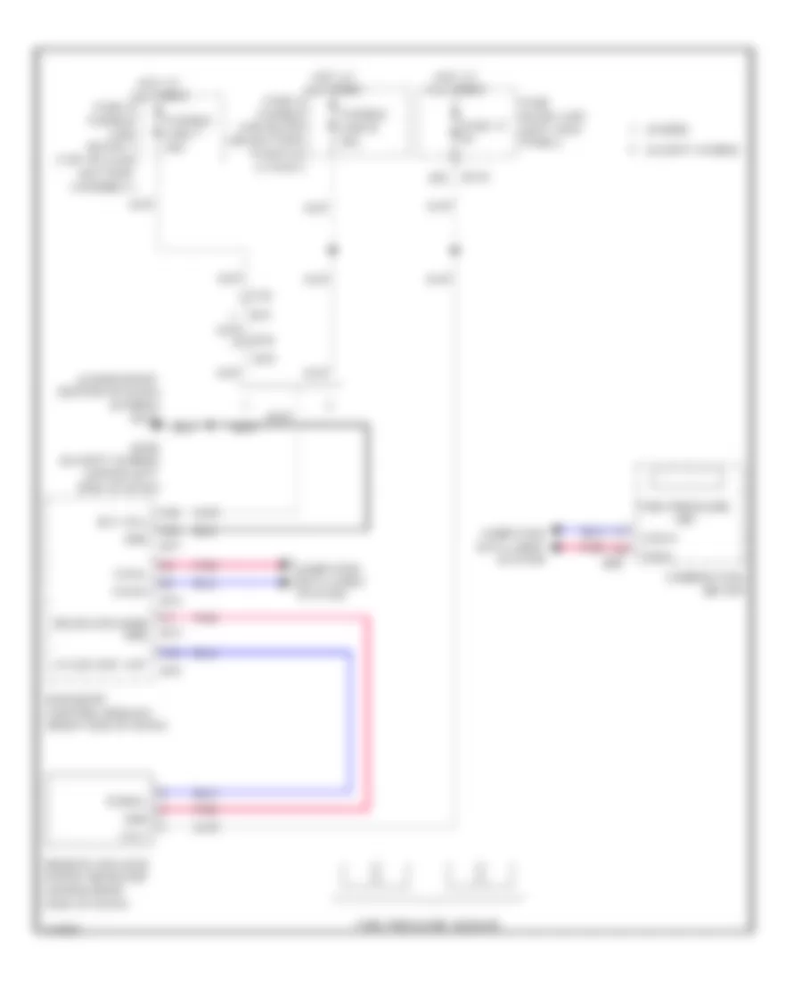
Automatic A/C Wiring Diagram (3 of 3) for Infiniti Q50 Hybrid Sport 2014
List of elements for Automatic A/C Wiring Diagram (3 of 3) for Infiniti Q50 Hybrid Sport 2014:
- (except hybrid: lower right center of dash) (hybrid: right rear of engine compt) (except hybrid) m111 (hybrid) e134
- (left rear of engine compt) (except hybrid) e137 (hybrid) e138
- (or pnk)
- A/c relay (except hybrid)
- Can-high
- Can-low
- Compressor (except hybrid) (left front of engine)
- Computer data lines system
- Cooling fan control module (rear of cooling fan 1)
- Cooling fan motor 1 (behind left side of radiator)
- Cooling fan motor 2 (behind right side of radiator)
- Cooling fan relay 1 (in fuse & fusible link block)
- Cpu
- E10
- E11
- E118
- E120
- E121
- E123
- E126
- E134 (right rear of engine compt)
- E25 m40
- E301
- E302
- E33
- E76 e14
- Ecm (engine control module) (except hybrid: under right end of dash) (hybrid: right front of engine compt)
- Ecv
- Engine controls system
- Engine coolant temp sens
- Engine coolant temperature sensor (rear of left cylinder bank)
- Except hybrid
- F10
- F11
- F12
- F20
- F4 f3
- F51 (front of right cylinder bank)
- F64
- Fuse & fusible link block (except hybrid: on battery positive (+) post) (hybrid: left front of engine compt)
- Fuse 10a
- Fusible link i 80a
- Fusible link o 50a
- Gnd
- Hot at all times
- Hybrid
- Ignition relay
- Ipdm e/r (intelligent power distribution module engine room) (right rear of engine compt)
- M36
- M37
- Magnet clutch
- Nca
- Pnk
- Pwr sply
- Red
- Refrigerant press sens
- Refrigerant pressure sensor (left side of condenser assembly)
- Sens gnd
- Sens gnd(ect sens)
- Sens sply
- Tan
- Tan (or pnk)
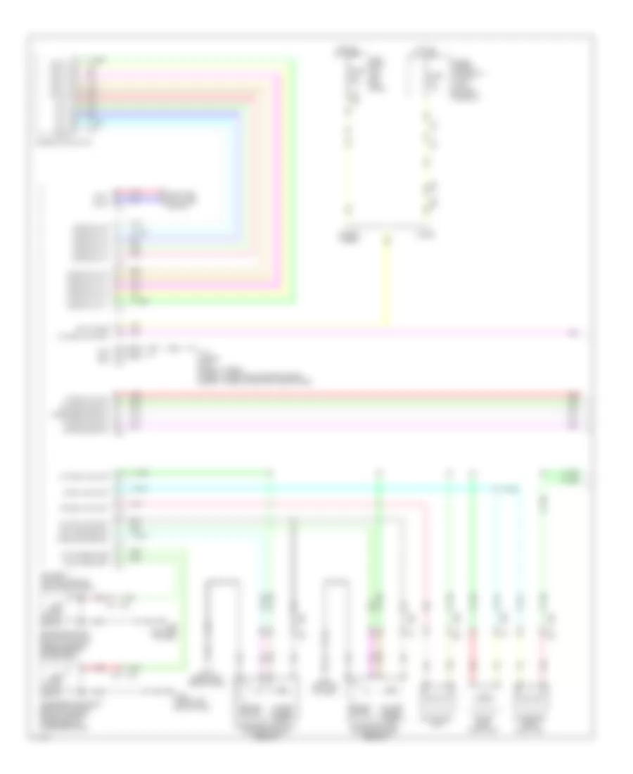
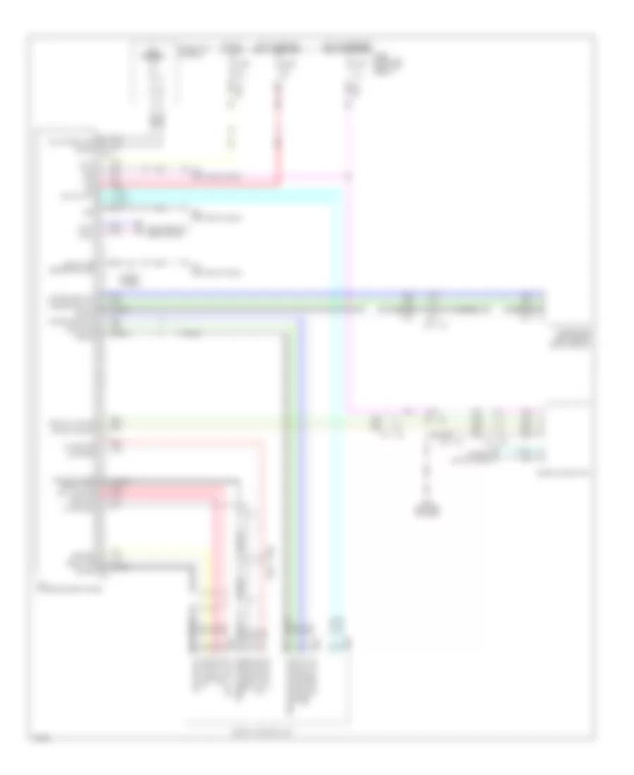
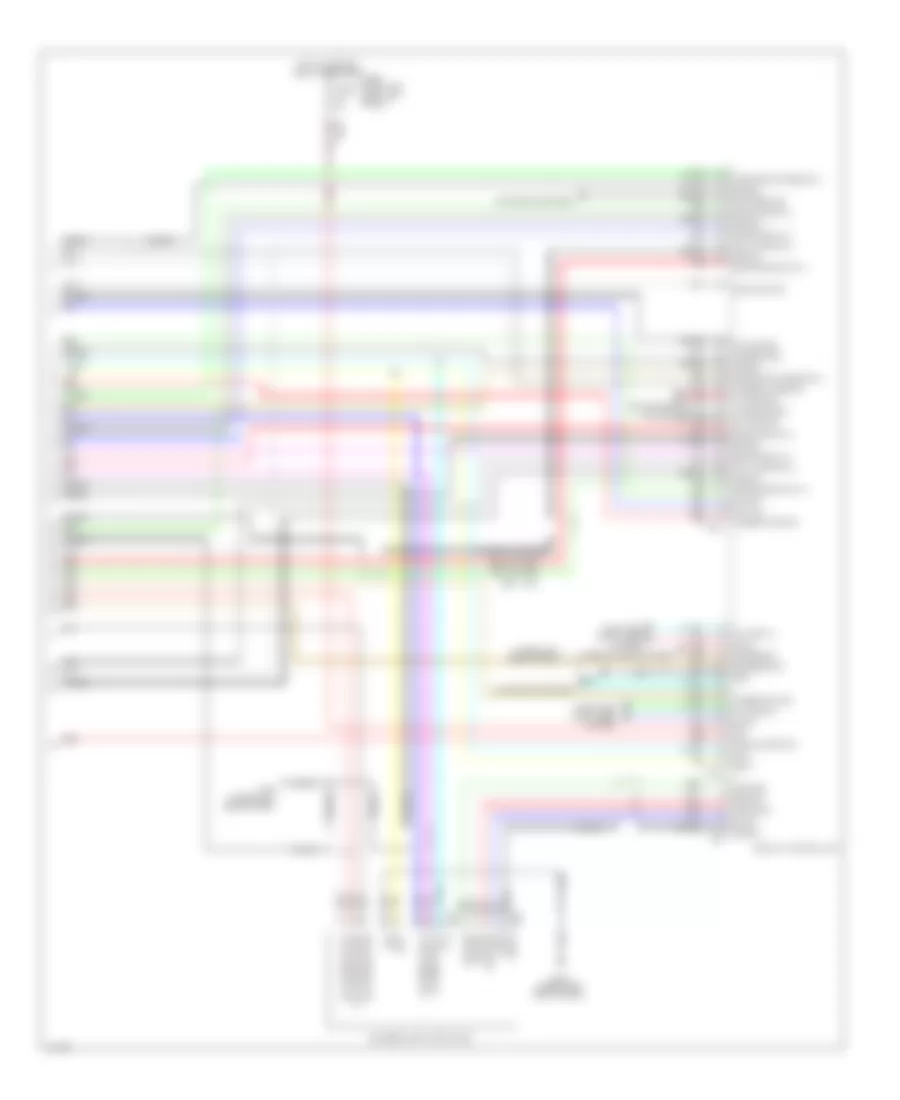
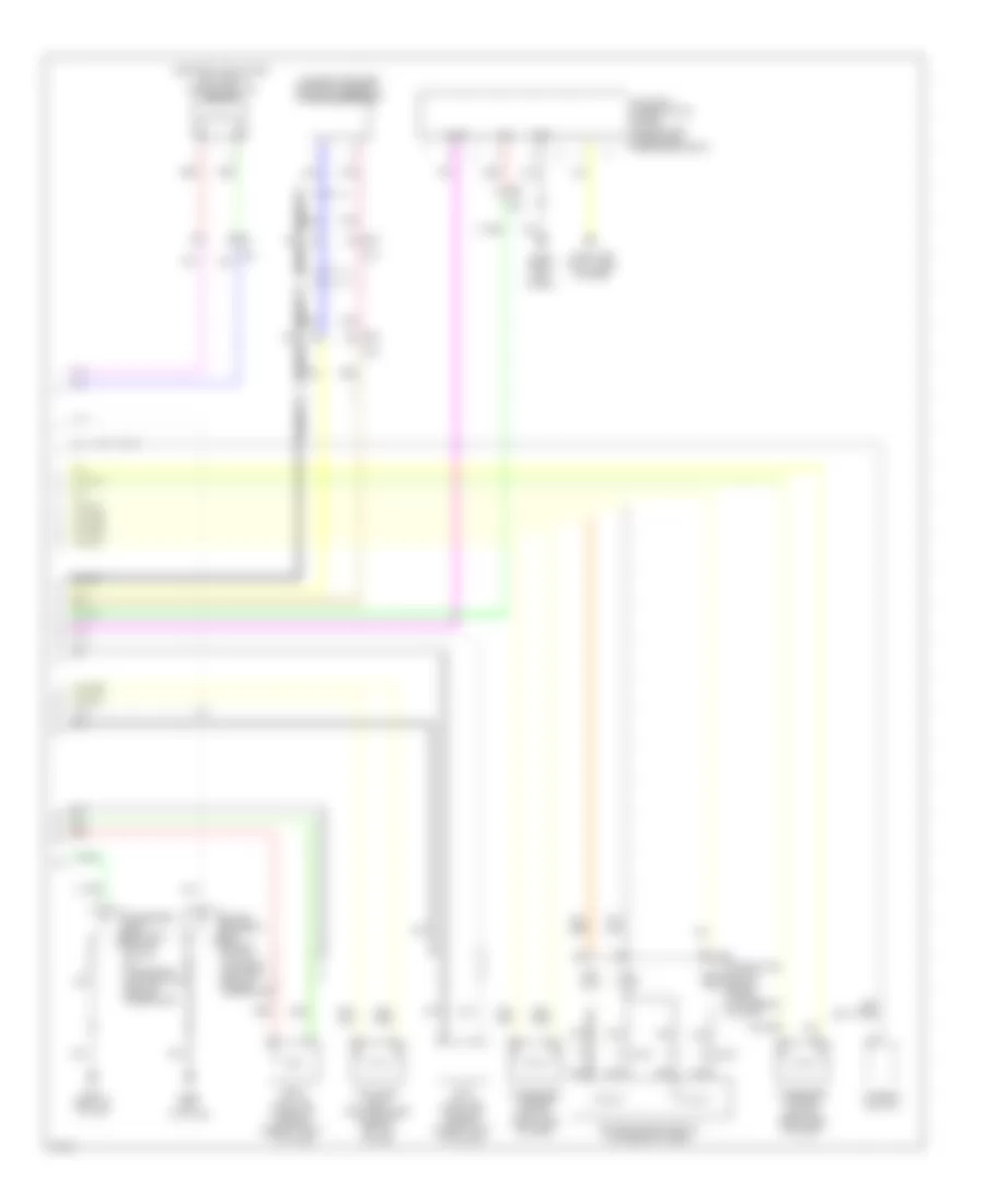
ANTI-LOCK BRAKES
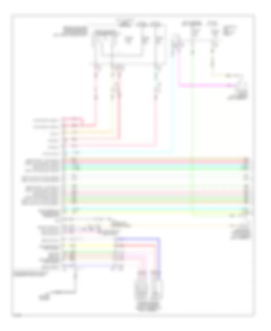
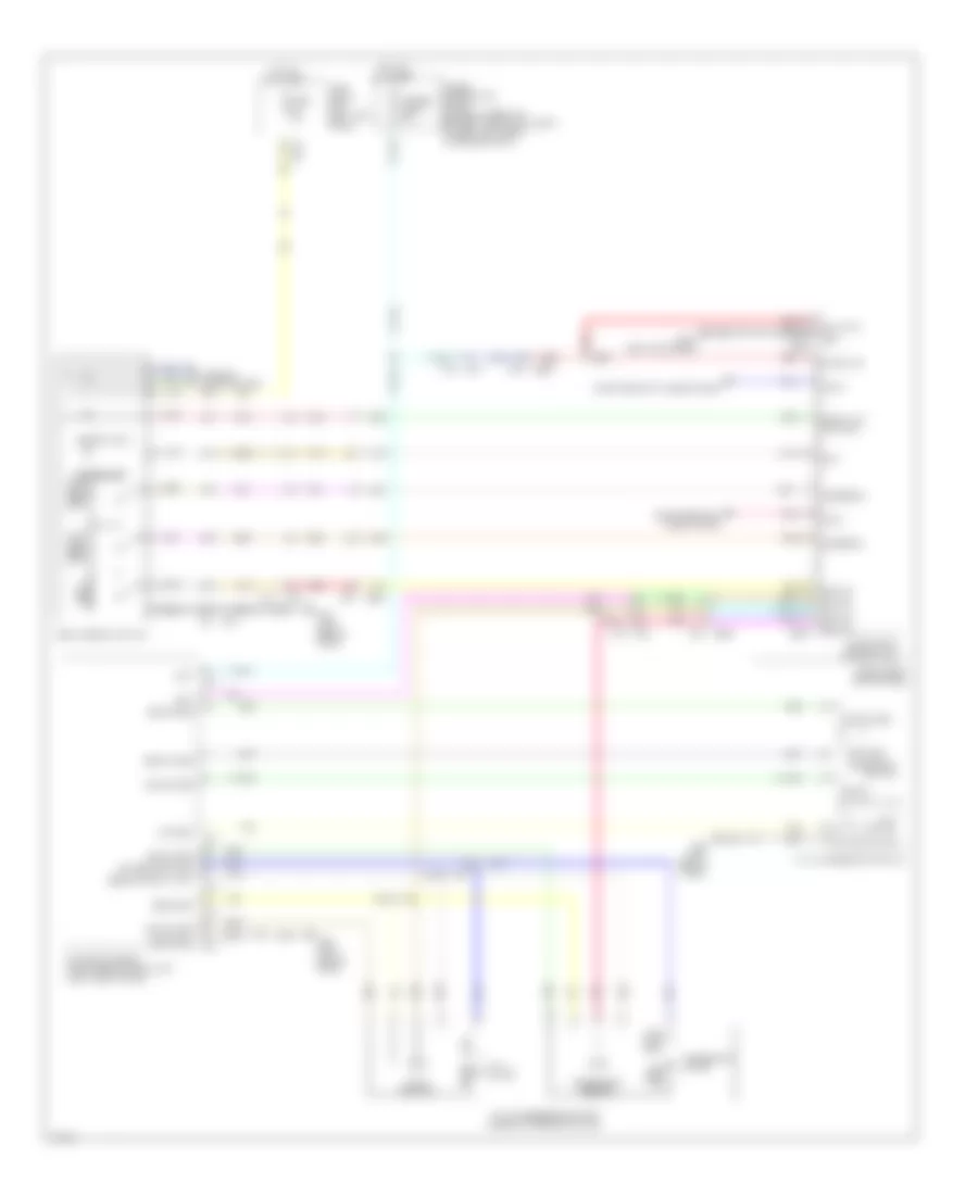
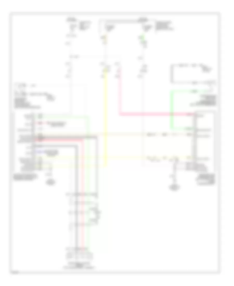
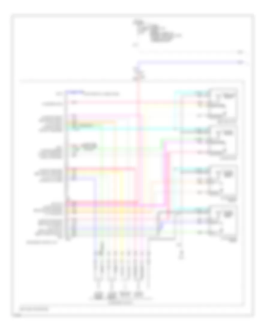
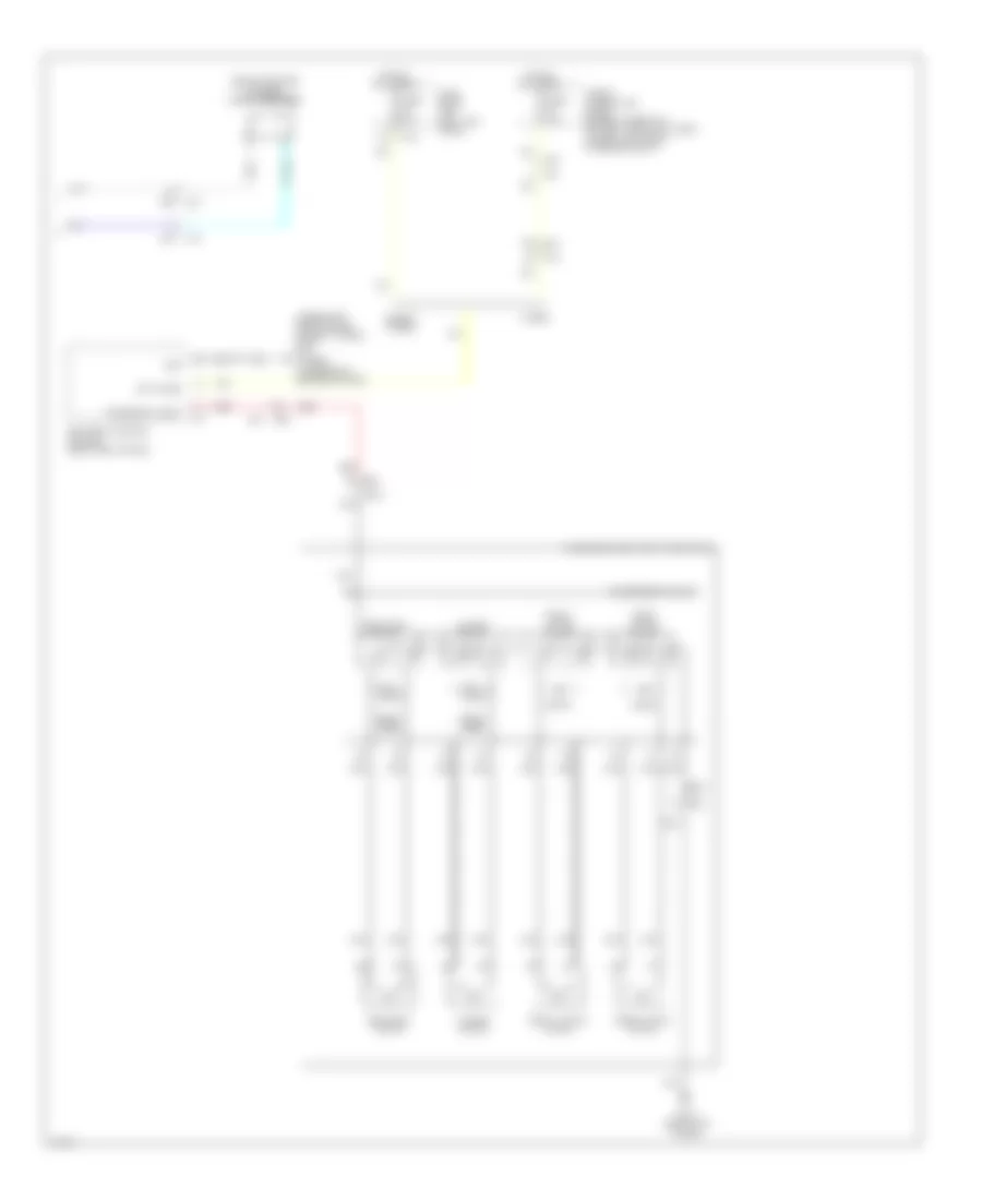
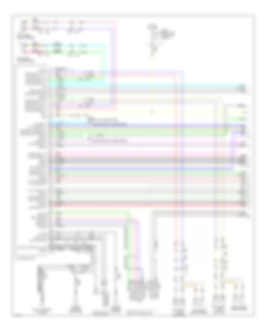
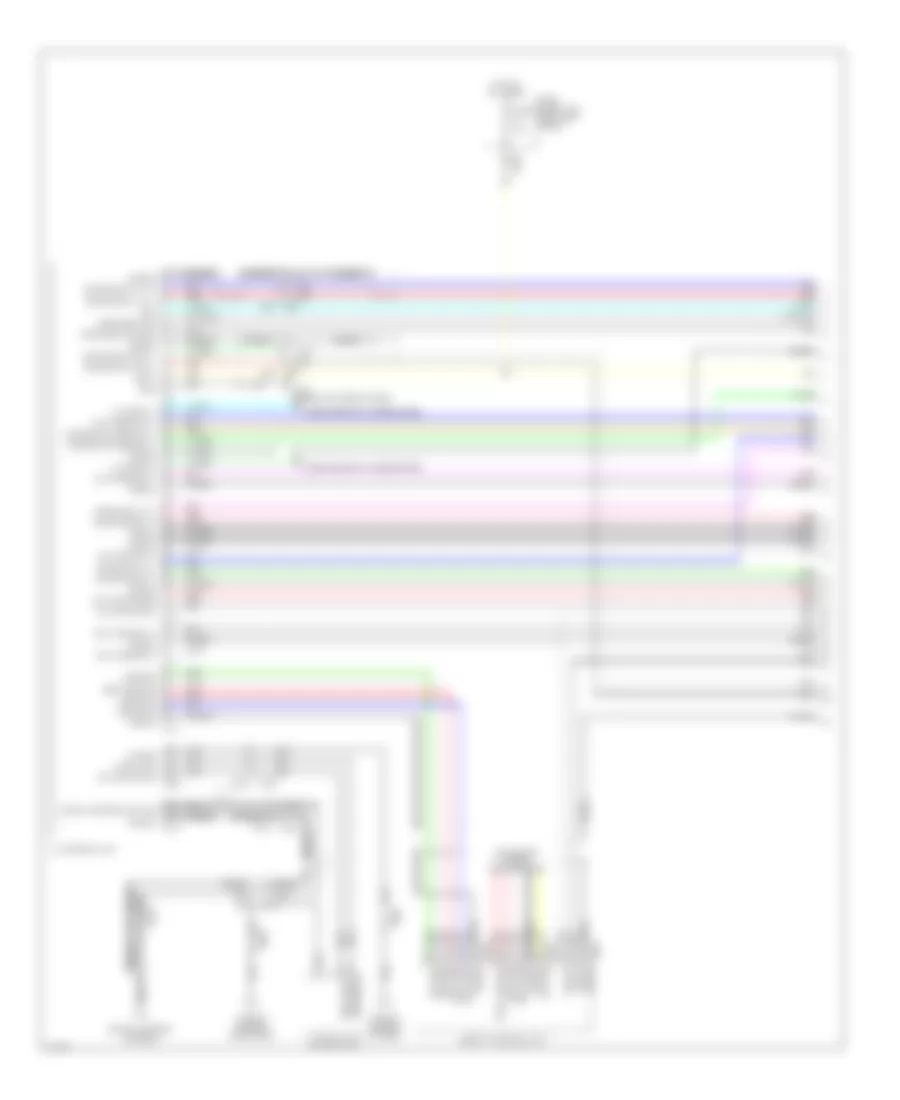
Anti-lock Brakes Wiring Diagram, Except Hybrid (1 of 2) for Infiniti Q50 Hybrid Sport 2014
List of elements for Anti-lock Brakes Wiring Diagram, Except Hybrid (1 of 2) for Infiniti Q50 Hybrid Sport 2014:
- (left end of dash) chassis control module
- (left end of dash) m93
- (left rear of engine compt) e140
- (or red)
- Abs actuator & electric unit (control unit) (left rear of engine compt)
- B6 c1
- Can-h
- Can-l
- Chas comm h
- Chas comm l
- Computer data lines
- Computer data lines system
- E121
- E137 (left rear of engine compt)
- E25
- E3 b10
- E47
- Fr-lh sen pwr
- Fr-lh sen sig
- Fr-rh sen pwr
- Fr-rh sen sig
- Fuse & fusible link block (on battery positive (+) post)
- Fuse 54 10a
- Fusible link l 30a
- Fusible link n 50a
- Gnd
- Hot at all times
- Hot w/ ignition relay energized
- Ign
- Ipdm e/r (intelligent power distribution module engine room) (right rear of engine compt)
- Left rear wheel sensor (on left rear wheel hub assembly)
- M39
- M40
- M93 (left end of dash)
- Mtr batt
- Pnk
- Red
- Right rear wheel sensor (on right rear wheel hub assembly)
- Rr-lh sen pwr
- Rr-lh sen sig
- Rr-rh sen pwr
- Rr-rh sen sig
- Sel sw (dn)
- Sel sw (up)
- Shield
- Steering angle sensor (upper steering column)
- Stp lp sw sig
- System
- Tan
- Transmissions system
- Triple switch
- Vac sen gnd
- Vac sen pwr
- Vac sen sig
- Vacuum sensor (on brake vacuum booster)
- Vdc off sw sig
- Vdc off switch
- Vlv batt
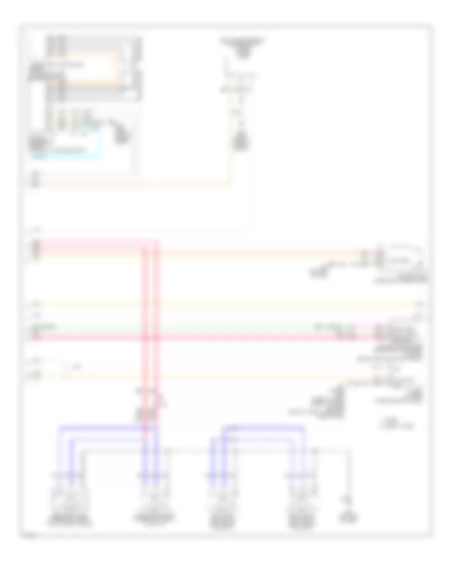
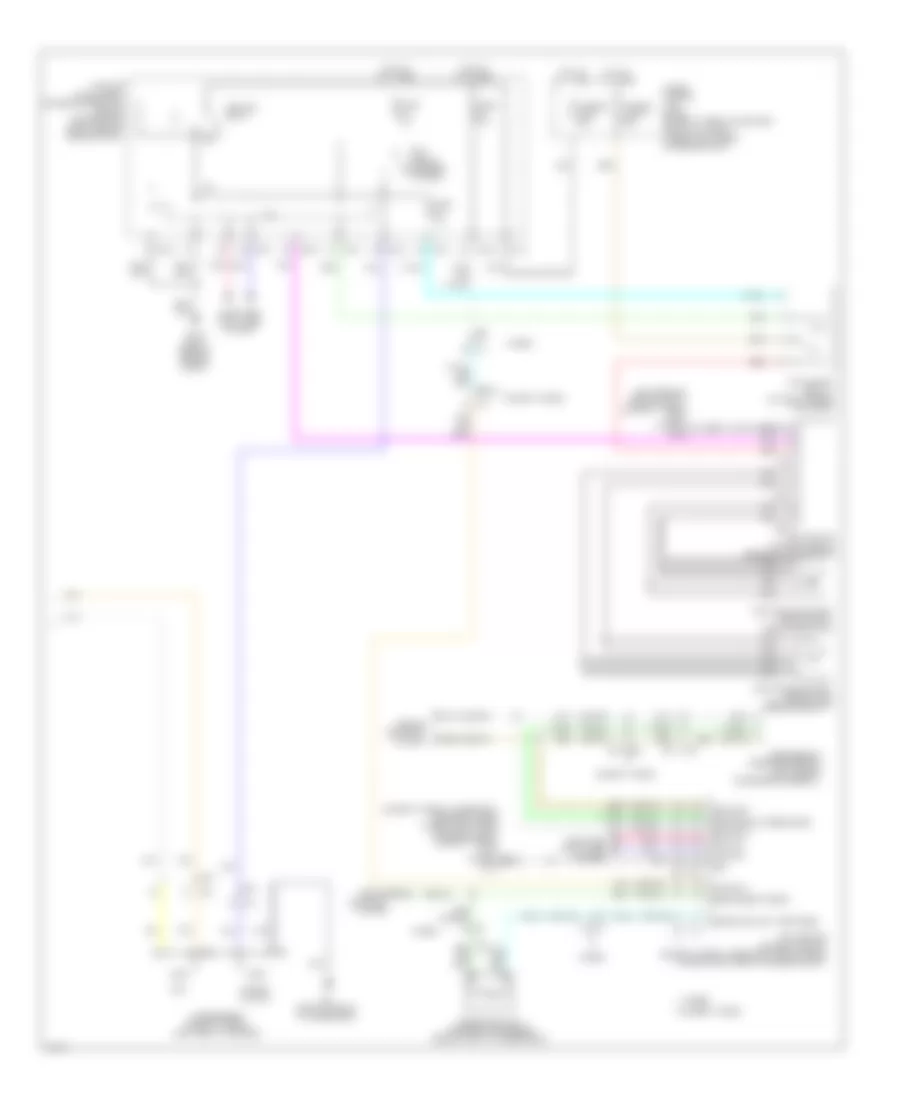
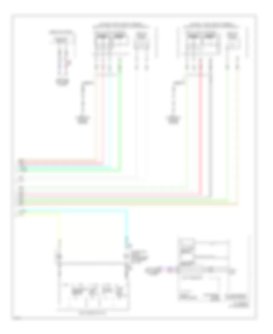
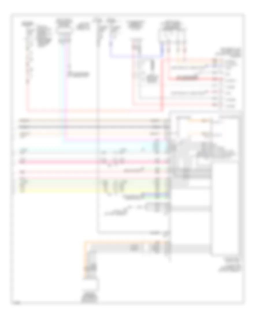
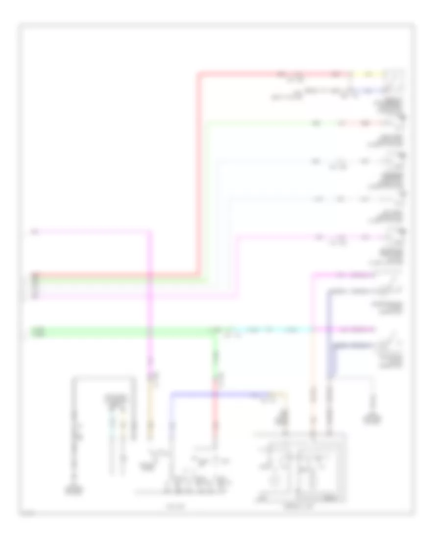
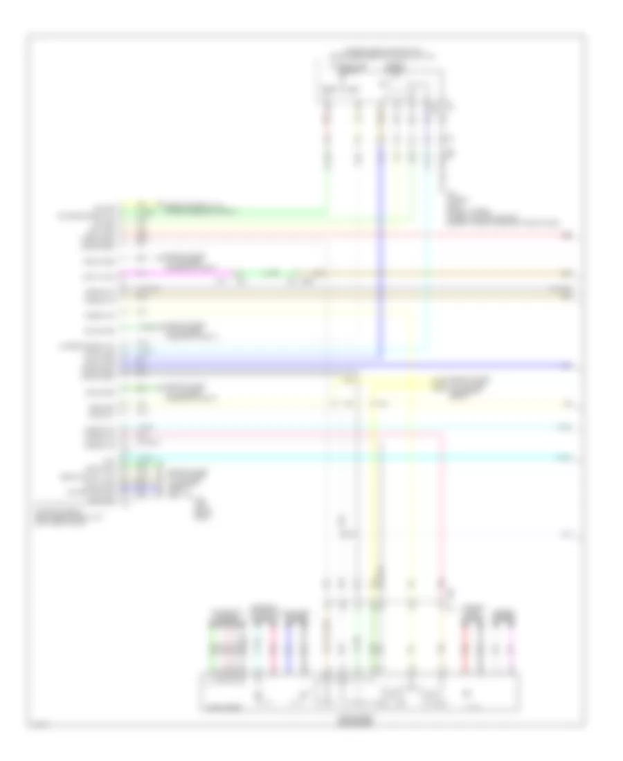
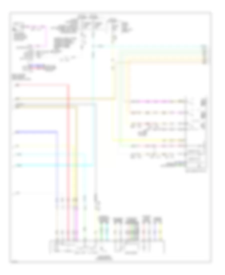
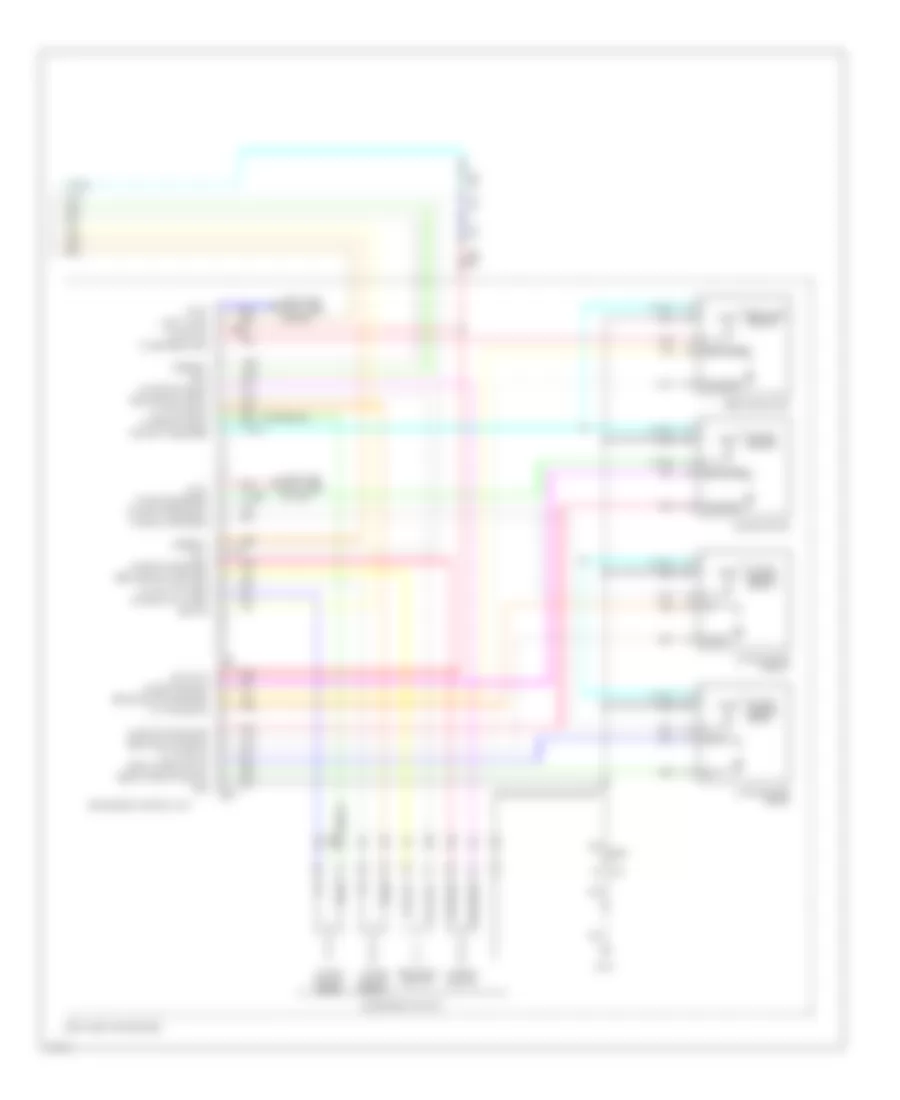
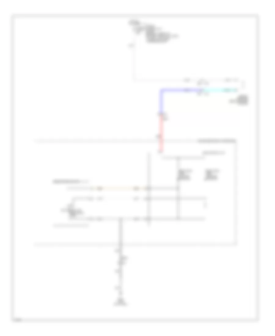
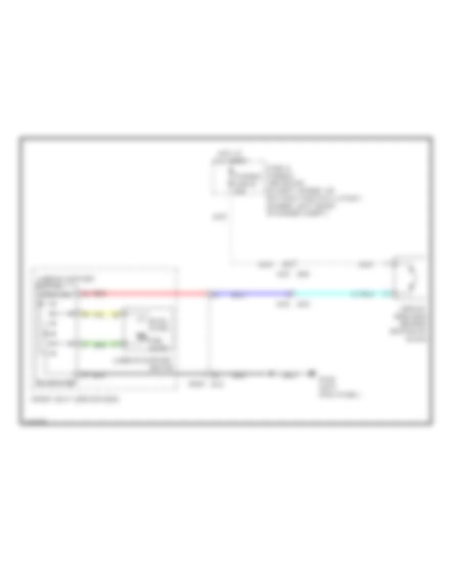
Anti-lock Brakes Wiring Diagram, Except Hybrid (2 of 2) for Infiniti Q50 Hybrid Sport 2014
List of elements for Anti-lock Brakes Wiring Diagram, Except Hybrid (2 of 2) for Infiniti Q50 Hybrid Sport 2014:
- 11f
- 28c
- 32c
- B39
- Batt pwr sply
- Brake fluid level switch (in brake fluid reservoir)
- Brk fluid lvl sw sig
- Can-h
- Can-l
- Combination meter
- Computer data lines system
- E137 (left rear of engine compt)
- E25
- E25 m40
- E64
- E65
- Exterior lights system
- Fuse 11 5a
- Fuse 12 10a
- Fuse 19 10a
- Fuse 6 10a
- Fuse block (j/b) (left kick panel)
- Gnd
- Hot at all times
- Hot w/ ignition relay energized
- Icc brake hold relay (w/ icc) (right rear of engine compt)
- Ign sig
- Left front wheel sensor (on left front wheel hub assembly)
- M133
- M40
- M57
- M58
- M93 (left end of dash)
- Parking brake switch (base of parking brake lever assembly)
- Pnk
- Prk brk sw sig
- Red
- Resistor (w/ icc) (right end of dash)
- Right front wheel sensor (on right front wheel hub assembly)
- Shift interlock system
- Stop lamp switch (top of brake pedal assembly)
- Tan
- Vdc ind, vdc off ind, abs ind & brake ind
- W/ icc
- W/o icc
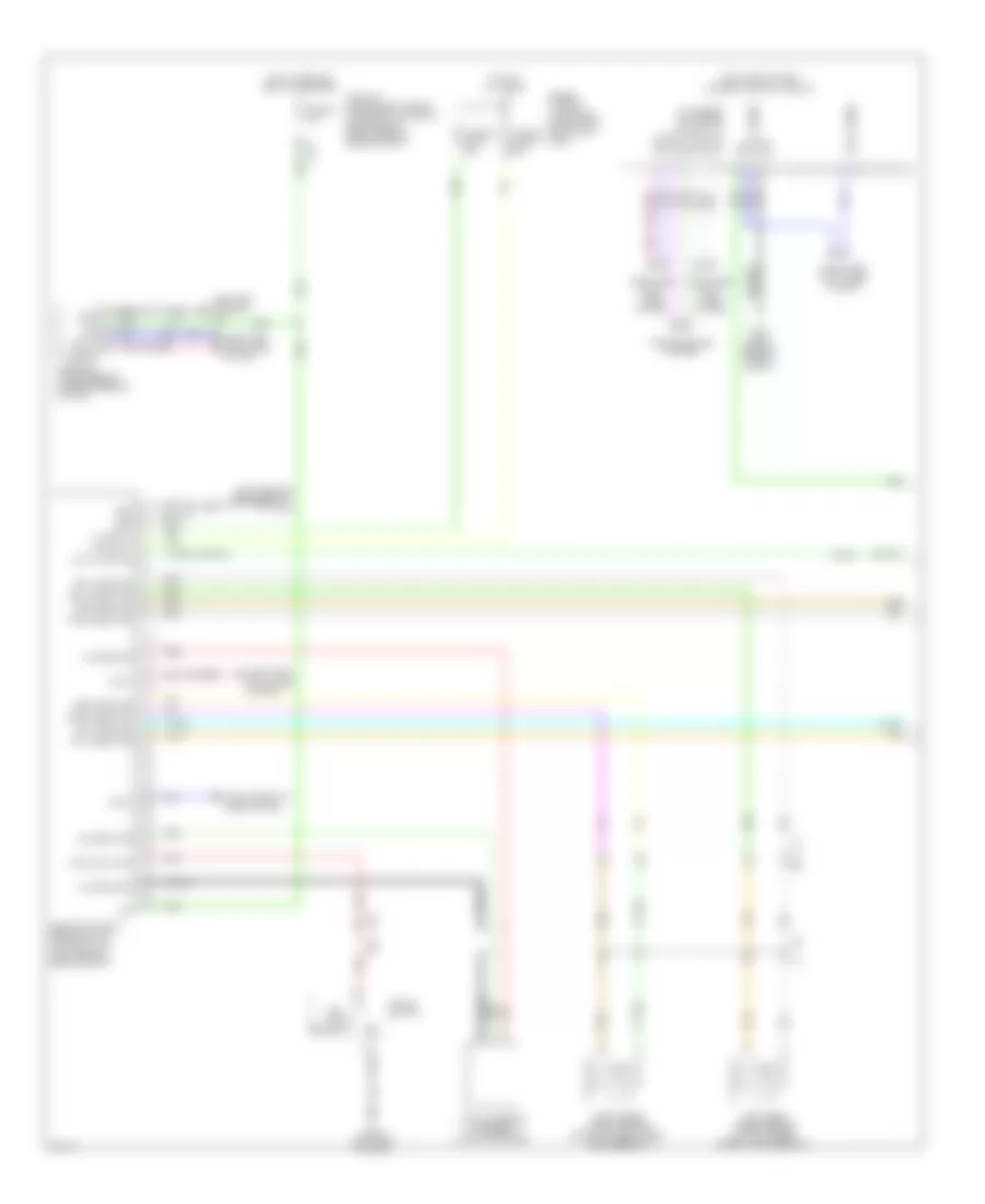
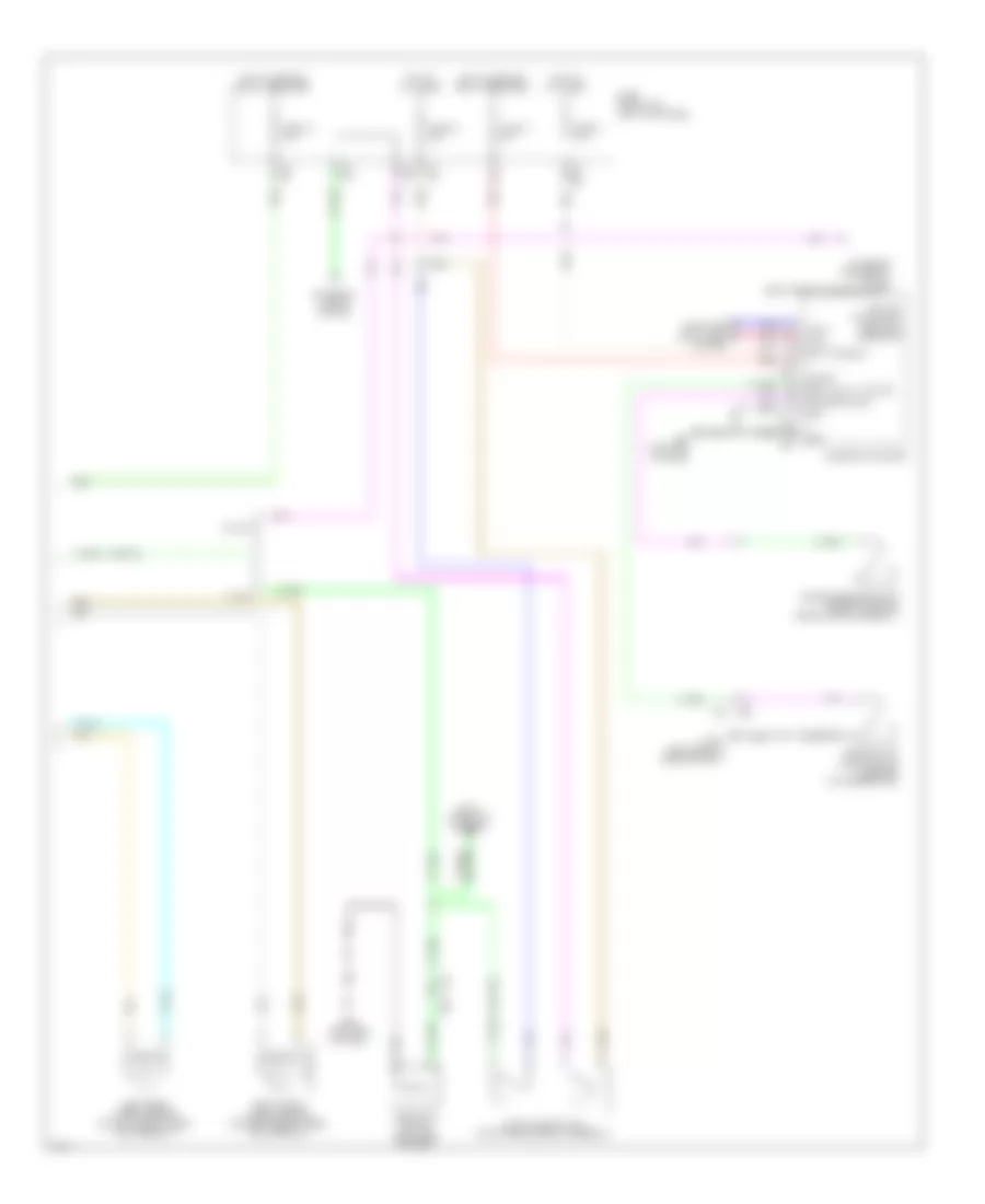
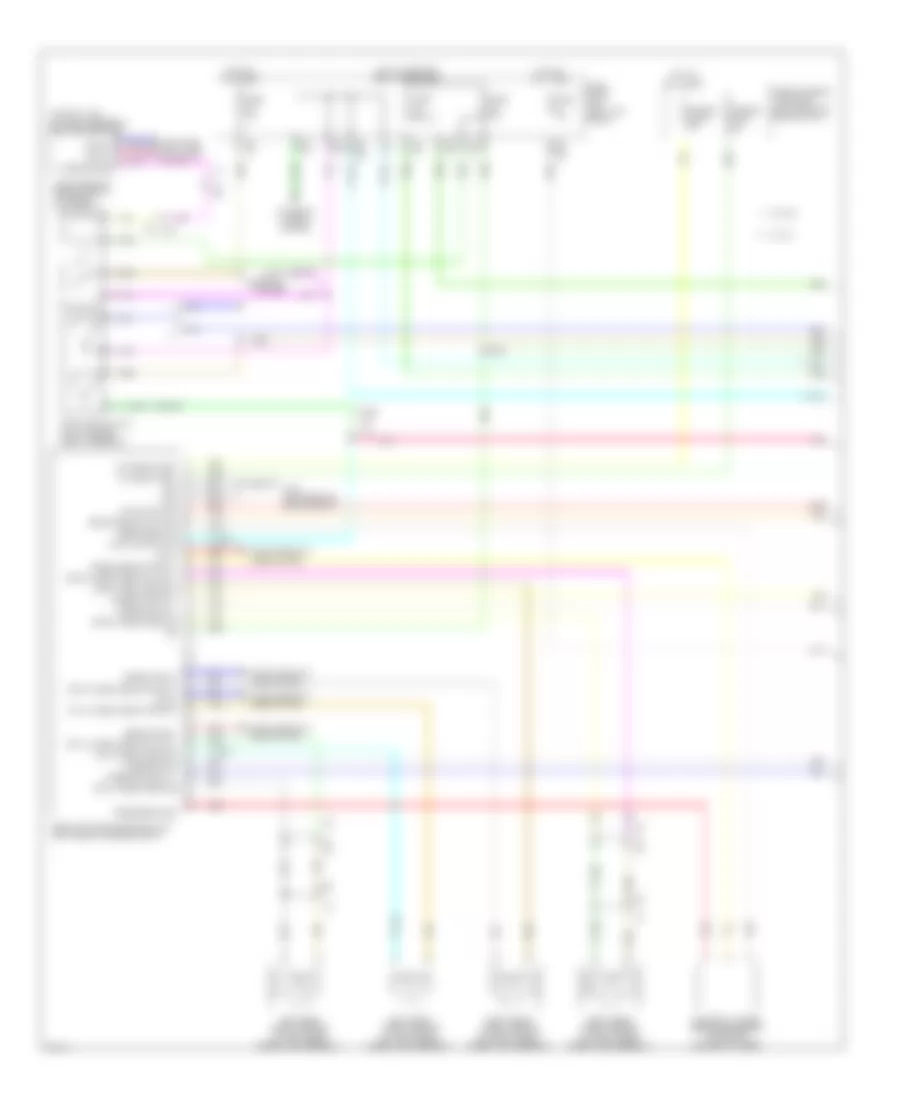
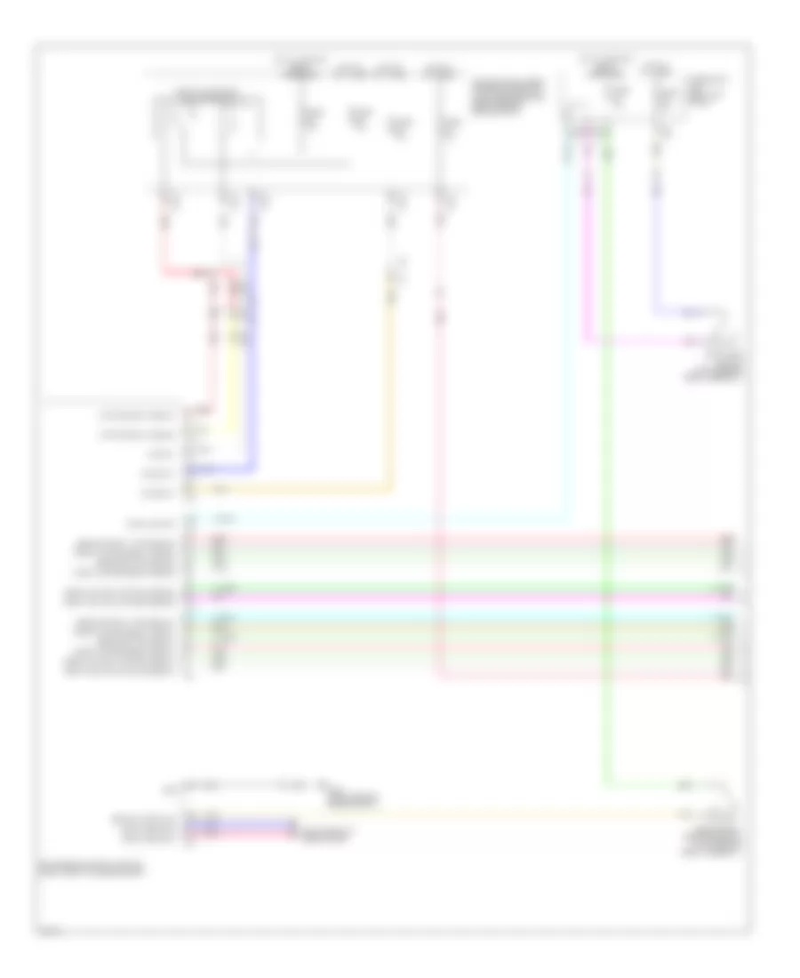
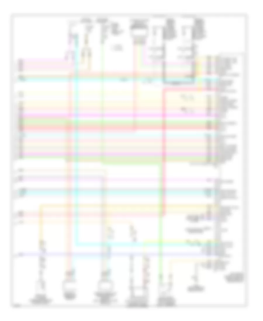
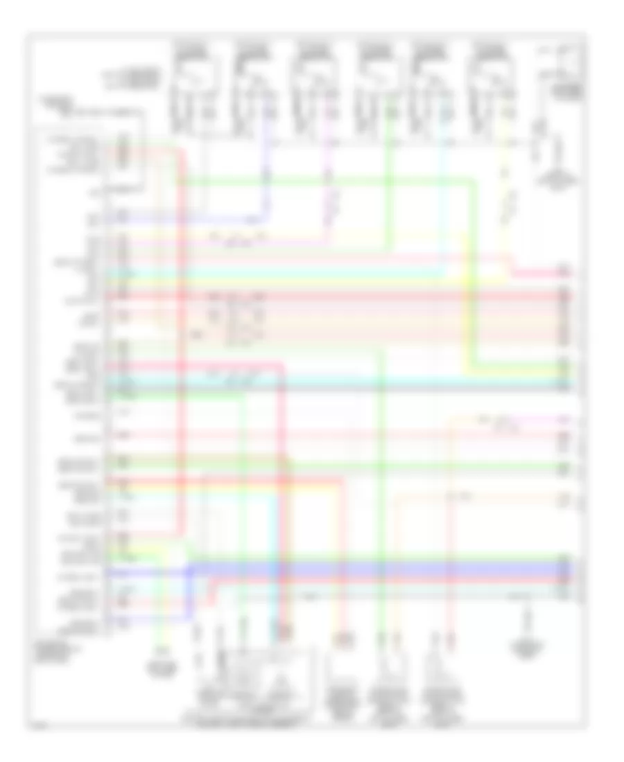
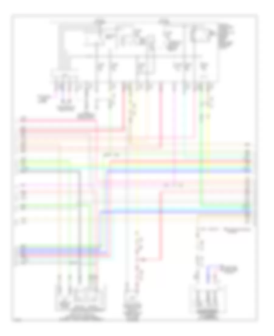
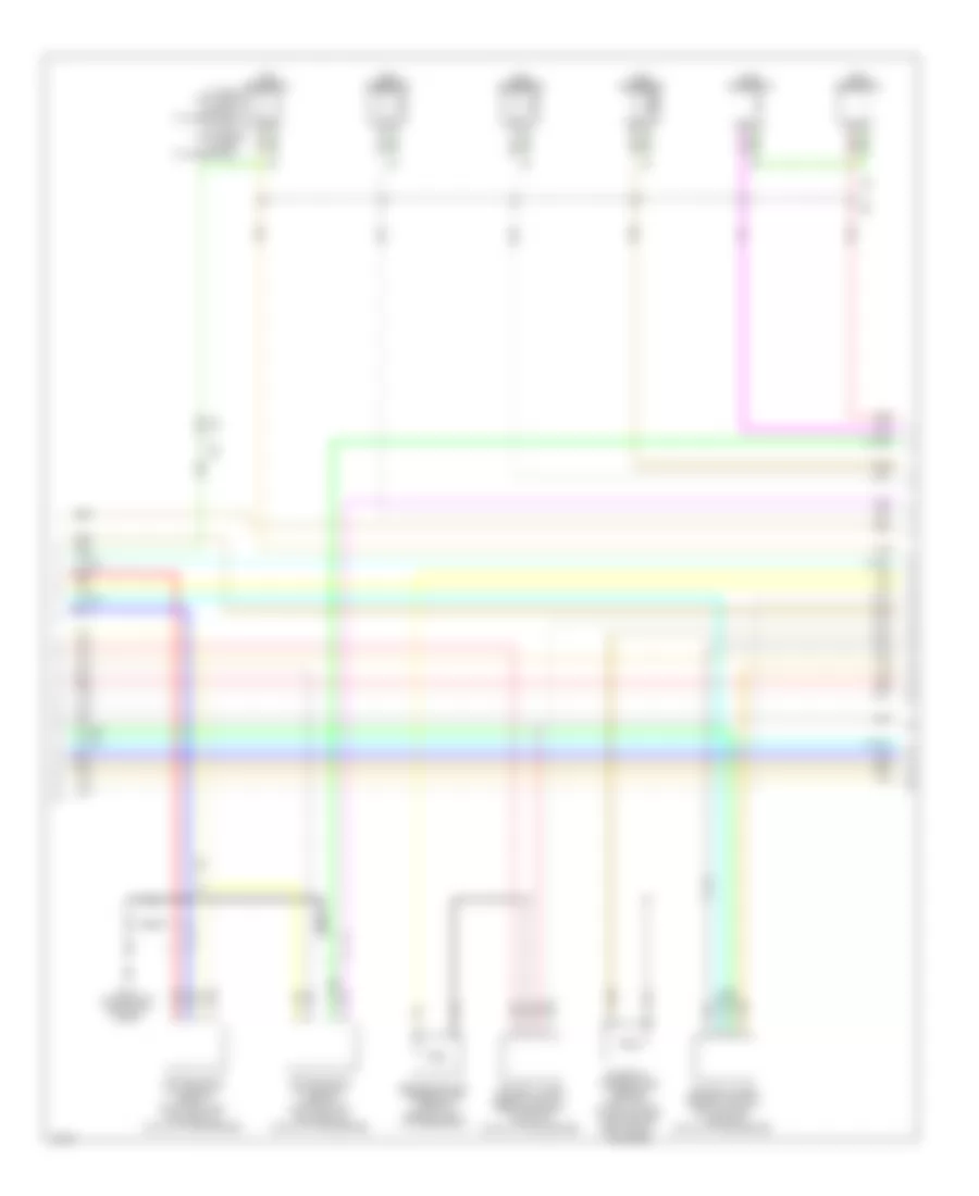
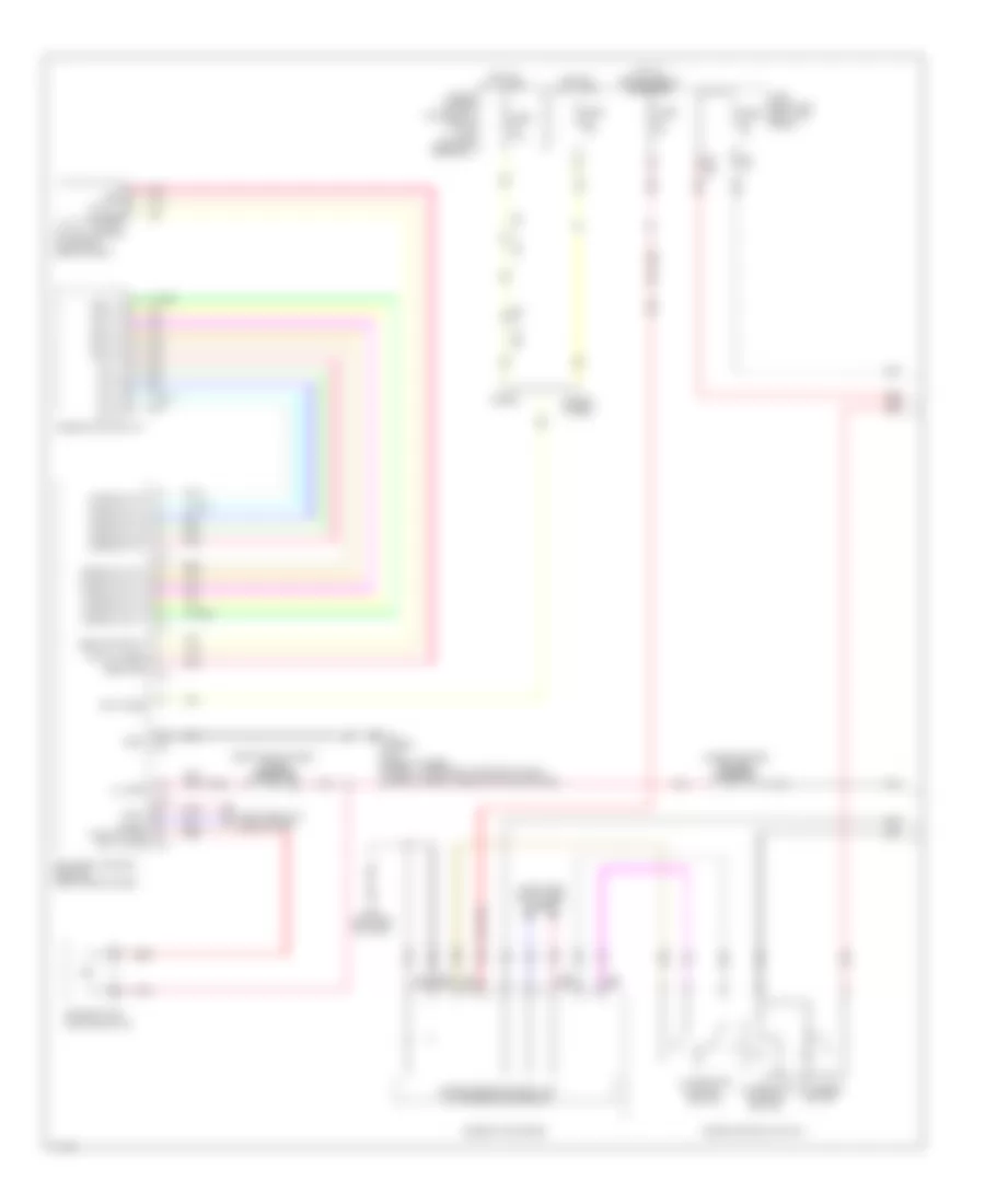
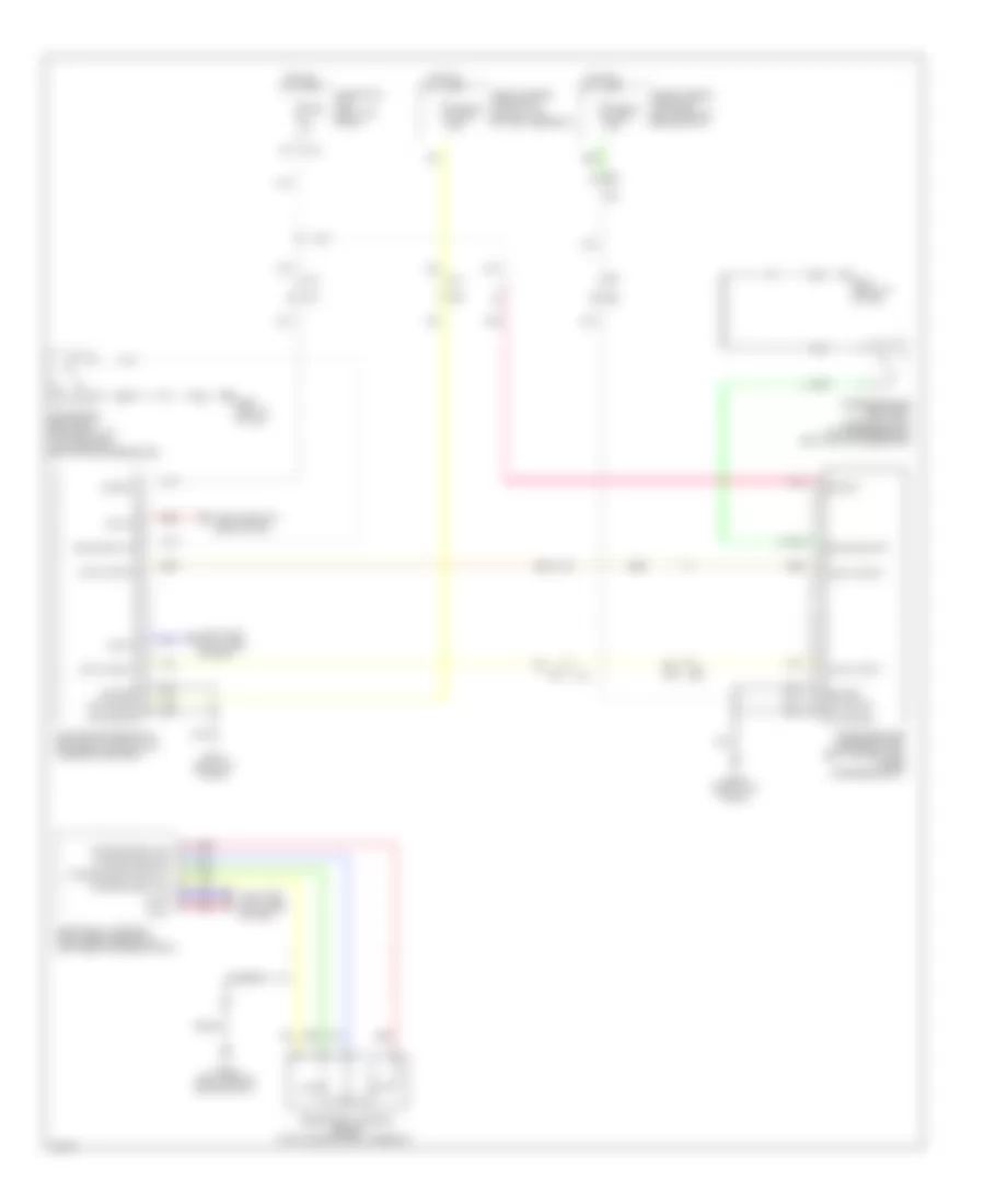
Anti-lock Brakes Wiring Diagram, Hybrid (1 of 3) for Infiniti Q50 Hybrid Sport 2014
List of elements for Anti-lock Brakes Wiring Diagram, Hybrid (1 of 3) for Infiniti Q50 Hybrid Sport 2014:
- (right rear of engine compt) icc brake hold relay
- (top of li-ion battery assembly) adas control unit
- 10f
- 11f
- 26c
- 28c
- Abs actuator & electric unit (left rear of engine compt)
- B10
- B29
- B39
- B5 c2
- Brake comm-h
- Brake comm-l
- Brake posi switch sig
- Can-h
- Can-l
- Comm-h
- Comm-l
- Computer data lines system
- E140 (left rear of engine compt)
- E3 b10
- E64
- E65
- Exterior lights system
- Fr lh wheel sens pwr sply
- Fr lh wheel sens sig
- Fr rh wheel sens pwr sply
- Fr rh wheel sens sig
- Fuse & fusible link block (left front of engine compt)
- Fuse 10a
- Fuse block (j/b) (left kick panel)
- Fusible link l 30a
- Fusible link n 50a
- G sens pwr sply
- G sensor gnd
- G sensor sig (+)
- G sensor signal (-)
- Gnd
- Hold rly sig
- Hot at all times
- Hot w/ ignition relay energized
- Ign
- Left front wheel sensor (on left front wheel hub assembly)
- Left rear wheel sensor (on left rear wheel hub assembly)
- M133
- Master cylinder pressure sensor (on brake master cylinder)
- Motor battery
- Pnk
- Press sens gnd
- Press sens pwr sply
- Press sens sig
- Red
- Right front wheel sensor (on right front wheel hub assembly)
- Right rear wheel sensor (on right rear wheel hub assembly)
- Rr lh wheel sens pow sply
- Rr lh wheel sens sig
- Rr rh wheel sens pow sply
- Rr rh wheel sens sig
- Shift interlock system
- Stop lamp sw sig
- Stop lamp switch (top of brake pedal assembly)
- Tan
- Valve battery
- Vdc off sw sig
- W/ icc
- W/o icc
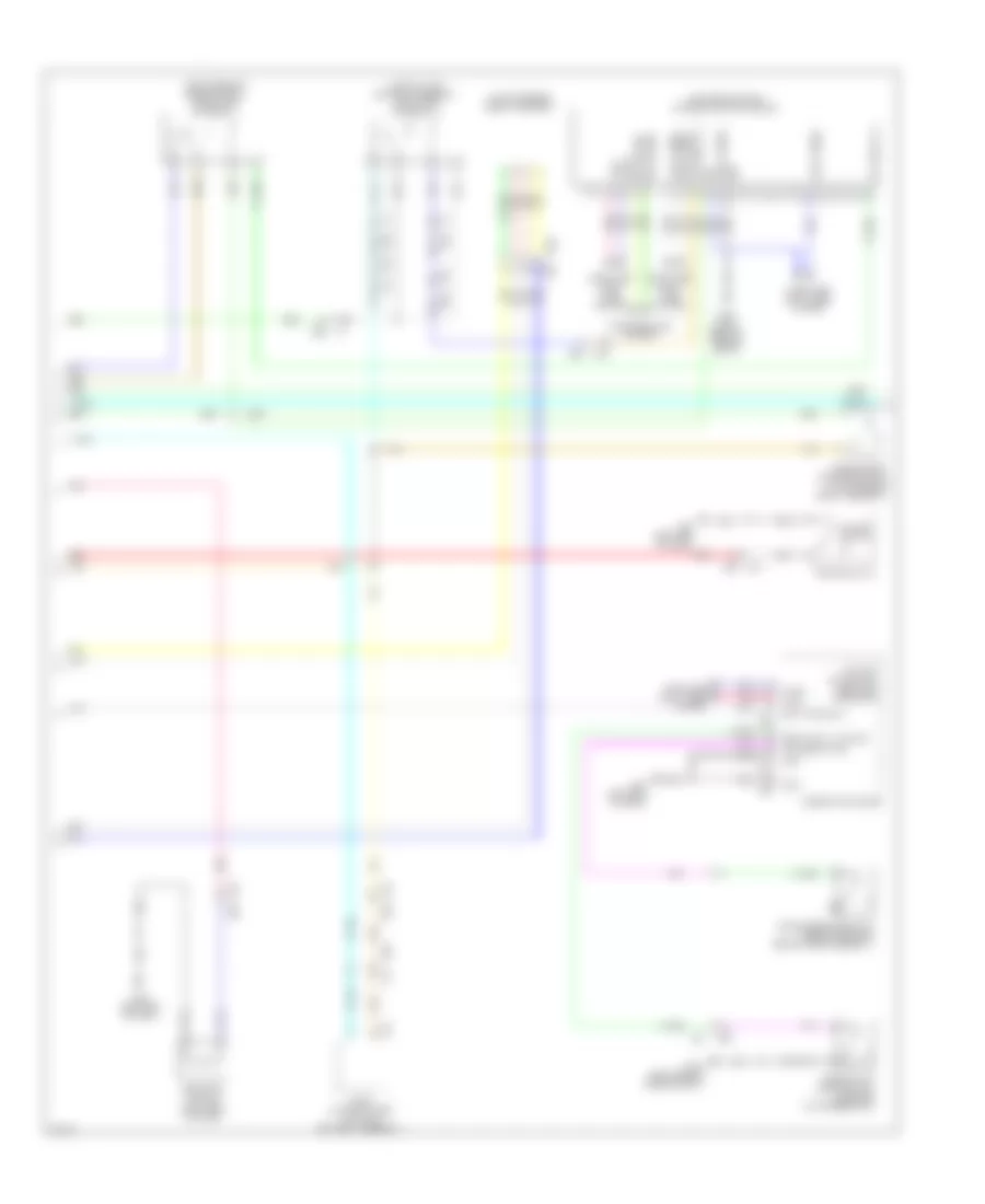
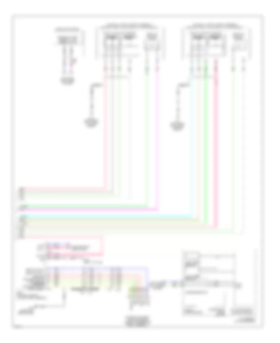
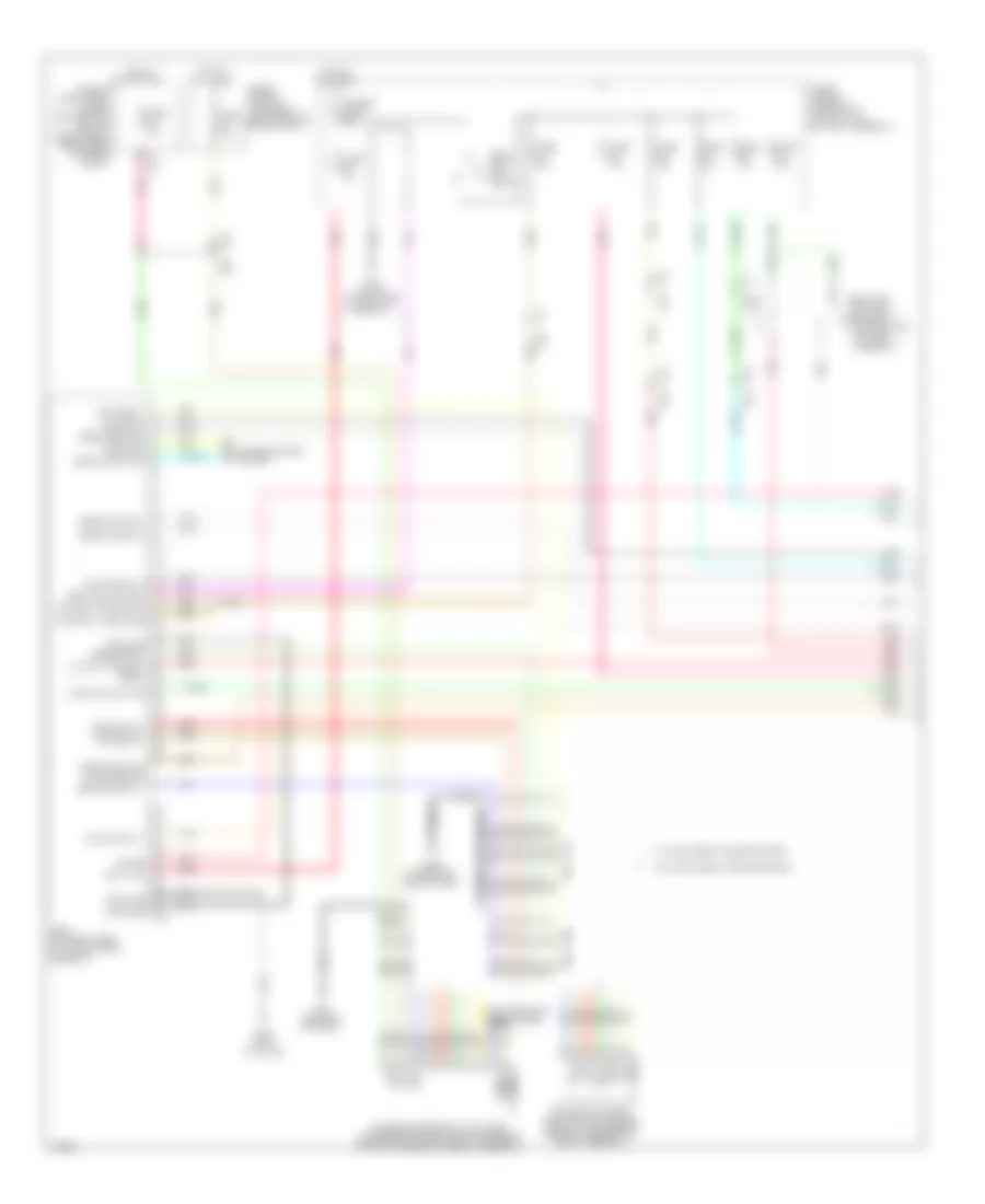
Anti-lock Brakes Wiring Diagram, Hybrid (2 of 3) for Infiniti Q50 Hybrid Sport 2014
List of elements for Anti-lock Brakes Wiring Diagram, Hybrid (2 of 3) for Infiniti Q50 Hybrid Sport 2014:
- (left end of dash) chassis control module
- (right rear of engine compt) stop lamp off relay 1
- (top of li-ion battery assembly) stop lamp off relay 2
- B10
- B15
- B17
- B18
- B29
- B30
- Batt pwr sply
- Brake fluid level switch (in brake fluid reservoir)
- Brake pedal position switch (top of brake pedal assembly)
- Brk fluid lvl sw sig
- Can-h
- Can-l
- Chas comm h
- Chas comm l
- Combination meter
- Computer data lines system
- E137 (left rear of engine compt)
- E25
- E25 m40
- E47
- Gnd
- Hpcm (top right side of li-ion battery assembly)
- Ign
- M18
- M19
- M39
- M40
- M57
- M58
- M93 (left end of dash)
- Parking brake switch (base of parking brake lever assembly)
- Pnk
- Prk brk sw sig
- Red
- Resistor (w/ icc) (right end of dash)
- Sel sw (dn)
- Sel sw (up)
- Stp lmp rly 1
- Stp lmp rly 2
- Tan
- Transmissions system
- Triple switch
- Vdc ind, vdc off ind, abs ind & brake ind
- Vdc off switch
- Yaw rate/side/ decel g sensor
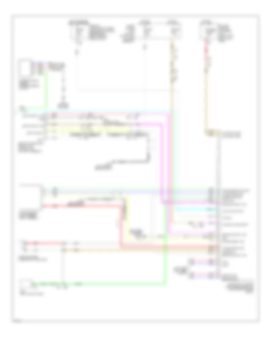
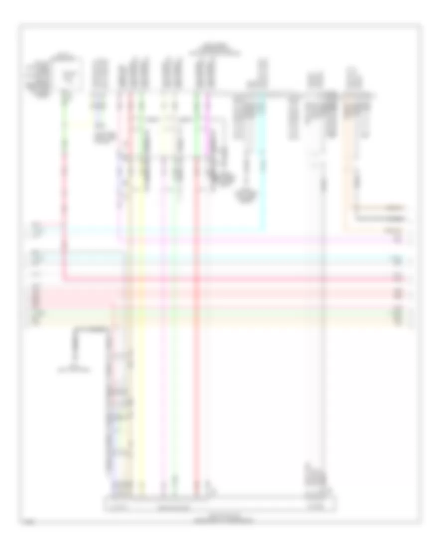
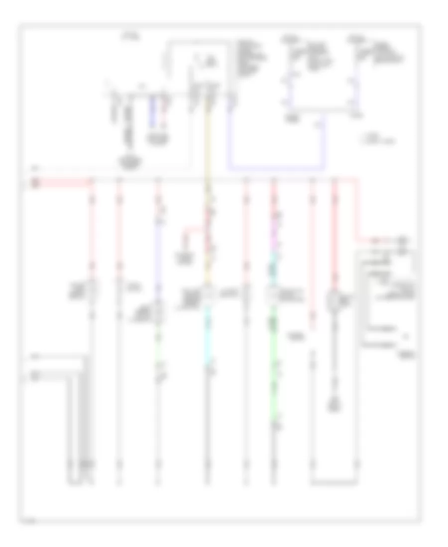
Anti-lock Brakes Wiring Diagram, Hybrid (3 of 3) for Infiniti Q50 Hybrid Sport 2014
List of elements for Anti-lock Brakes Wiring Diagram, Hybrid (3 of 3) for Infiniti Q50 Hybrid Sport 2014:
- (left rear of engine compt) e137
- B10
- B18
- B29
- B30
- B33
- B35
- Batt
- Battery terminal w/ fusible link (on battery positive (+) post)
- Bcm (right end of dash)
- Brake c0mm-h
- Brake c0mm-l
- Brake pwr sply sig
- Brk pwr sply
- Brk pwr sply sig
- Buzzer pwr sply
- Buzzer sig
- Can-h
- Can-l
- Computer data lines system
- Control module batt
- Dr sw sig
- E121
- E137 (left rear of engine compt)
- E138 (left rear of engine compt)
- E25
- E50
- E53
- Electrically-driven intelligent brake unit (left rear of engine compt)
- Fuse & fusible link block 1 (top of li-ion battery assembly)
- Fuse 10a
- Fusible link d 50a
- Gnd
- H12
- Hot at all times
- Hot w/ ignition relay energized
- Ipdm e/r (intelligent power distribution module engine room) (right rear of engine compt)
- M15
- M19
- M40
- M93 (left end of dash)
- Motor battery
- Pnk
- Pwr sw
- Red
- Shield
- Steering angle sensor (upper steering column)
- Stop lamp sw sig
- Stroke sens 1 sig
- Stroke sens 2 sig
- Stroke sens gnd
- Stroke sens pwr sply
- Stroke sensor (top of brake pedal assembly)
- T22 (top of li-ion battery assembly)
- T27
- Warning buzzer (under right headlamp)
ANTI-THEFT
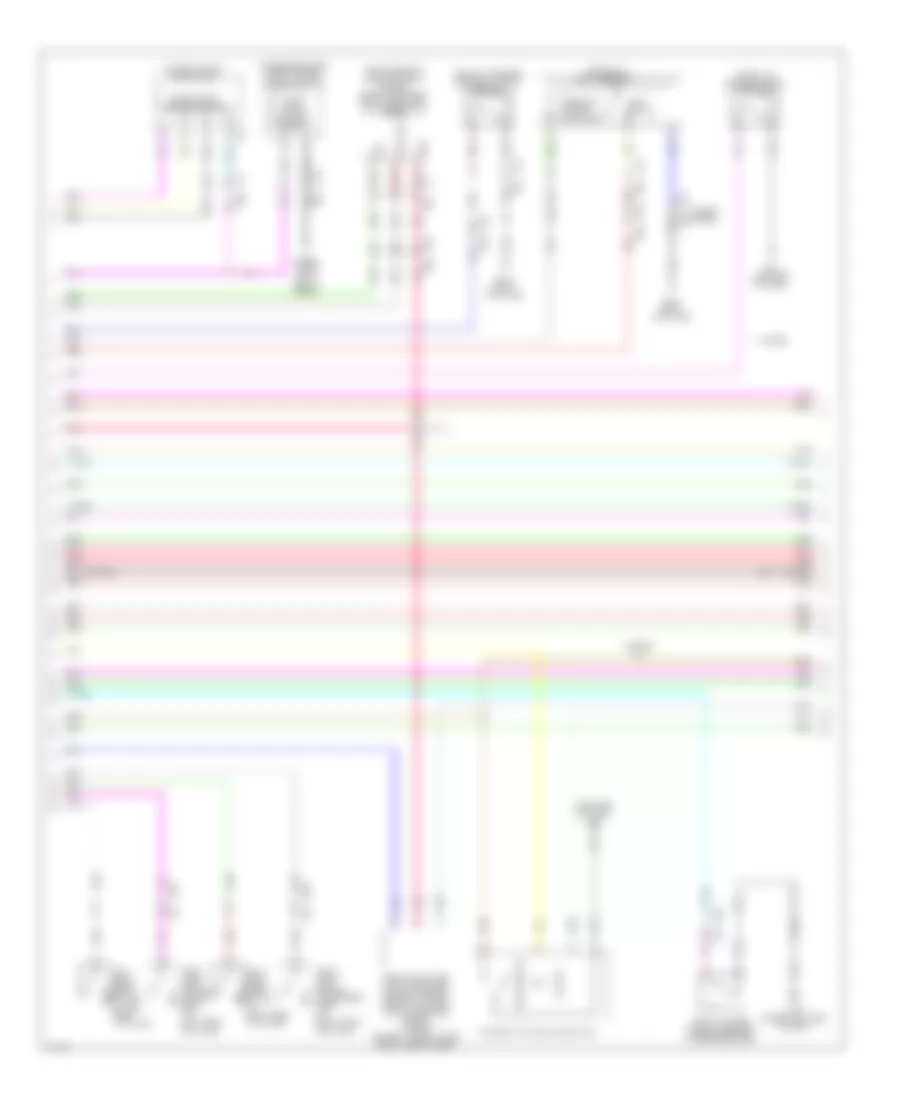
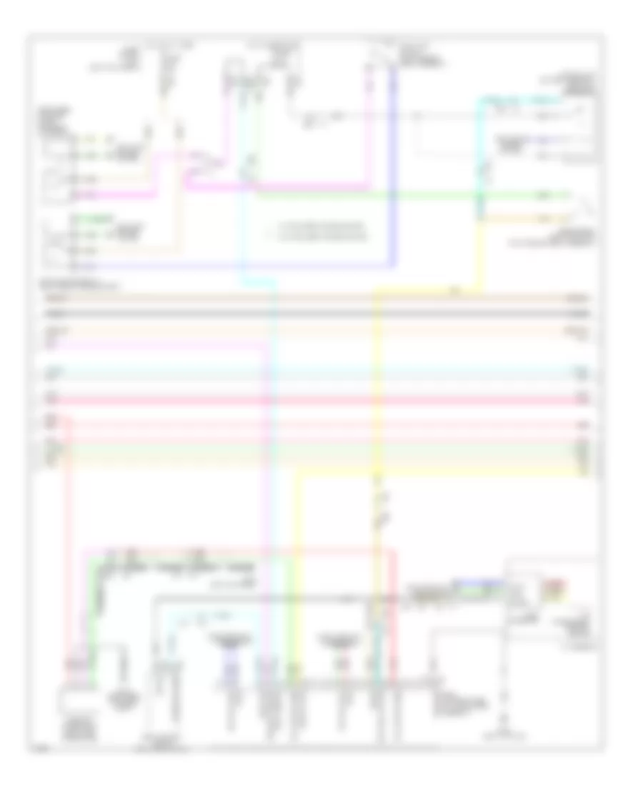
Forced Entry Wiring Diagram (1 of 5) for Infiniti Q50 Hybrid Sport 2014
List of elements for Forced Entry Wiring Diagram (1 of 5) for Infiniti Q50 Hybrid Sport 2014:
- (hybrid: lower right center of dash) (except hybrid: left end of dash)
- (right end of dash) bcm (body control module)
- (right side of luggage compt) fuel filler lid lock actuator
- A/t shift select pwr sply strt rly ctrl
- Acc/on ind
- B18
- B35
- B62
- B62 m22
- B86
- Bat (f/l)
- Between full stroke & n
- Can-h
- Can-l
- Comm line
- Computer data lines system
- D18 m34
- D4 m33
- Detent sw
- Dongle link
- Door lock actuator
- Dr door req sw
- Dr door unlck sens
- Drv door ant+
- Drv door ant-
- Drv door sw
- E25
- Except hybrid
- Exterior lights system
- Fl lid lk o/p
- Fl lid unlck o/p
- Front door lock assembly (driver side)
- Front door lock assembly (passenger side)
- Full stroke
- Fuse & fusible link block (except hybrid: on battery positive (+) post) (hybrid: left front of engine compt)
- Fusible link m 40a
- Fusible link t 40a
- Gnd
- Hot at all times
- Hybrid
- I-key warn buzzer
- Inside key ant (instrument lower)- inside key ant (instrument lower)+ inside key ant (console)- inside key ant (console)+
- Inside key ant(trunk)+
- Inside key ant(trunk)-
- Inside key antenna (console) (under rear of center console)
- Inside key antenna (instrument lower) (lower right center of dash)
- Inside key antenna (trunk room) (under center of rear shelf)
- Interior lights system
- Key cylinder switch
- Kyls ent receiv comm
- Kyls ent receiver rear (comm) receiver (rear) pwr sply
- Lh rear door sw
- Lh turn sig
- Lock
- M111 (hybrid) m93 (except hybrid)
- M13
- M14
- M15
- M155
- M16
- M17
- M19
- M22
- M40
- M93 (hybrid) m108 (except hybrid) (hybrid: left end of dash) (except hybrid: upper left side of dash)
- M93 (left end of dash)
- M95
- One touch unlk sens (dr)
- One touch unlk sens (pass)
- Outside key antenna (rear bumper) (behind center of rear bumper fascia)
- P/n position
- Pass door ant+
- Pass door ant-
- Pass door req sw
- Pass door sw
- Pass door unlck out
- Pnk
- Push sw
- Rear bmpr ant+
- Rear bmpr ant-
- Receiver/sensor gnd
- Red
- Rh rear door sw
- Rh turn sig
- Room lamp pwr sply
- Room lamp timer ctrl
- Rr, rl door lk o/p
- Rr, rl door unlk o/p
- Security ind
- Stop lmp sw
- Stop lmp sw 2
- T25 b41
- T27
- T54
- Tan
- Tr lid op cancel sw
- Tr lid opnr sw
- Tr room lmp sw
- Triple switch
- Trunk lid open
- Trunk lid opener sw
- Unlock
- Unlock sensor
Forced Entry Wiring Diagram (2 of 5) for Infiniti Q50 Hybrid Sport 2014
List of elements for Forced Entry Wiring Diagram (2 of 5) for Infiniti Q50 Hybrid Sport 2014:
- (left end of dash) m93
- (passenger side) front power window switch
- (right rear of luggage compt) (hybrid) remote keyless entry receiver (rear)
- Acc/on
- B107 (right "b" pillar)
- B18
- B62
- B62 m22
- Canada
- D18 m34
- D4 m33
- Door lock & unlock switch
- Except hybrid
- Front door switch (driver side) (in left front "b" pillar)
- Front door switch (passenger side) (in right front "b" pillar)
- Front outside handle assembly (passenger side)
- Gnd
- Hybrid
- Lamp switch
- Left rear door switch (in left rear "c" pillar)
- M108 (upper left side of dash)
- M19
- M22
- M34 d18
- M93 (left end of dash)
- Pnk
- Power window main switch
- Push switch
- Push-button ignition switch
- Pwr sply
- Red
- Remote keyless entry receiver (except hybrid) remote keyless entry receiver (front) (hybrid) (except hybrid: upper right side of dash)
- Right rear door switch (in right rear "c" pillar)
- Sig
- T48 b66
- T5 b65
- Tan
- Trunk lid lock assembly
- Trunk lid opener actuator
- Trunk lid opener cancel switch
- Trunk lid opener request switch assembly
Forced Entry Wiring Diagram (3 of 5) for Infiniti Q50 Hybrid Sport 2014
List of elements for Forced Entry Wiring Diagram (3 of 5) for Infiniti Q50 Hybrid Sport 2014:
- (upper rear of driver side door) front one touch unlock sensor assembly (driver side)
- (upper rear of passenger side door) front one touch unlock sensor assembly (passenger side)
- A/t assembly (on transmission)
- B18 m19
- B62 m22
- Can-h
- Can-l
- Canada
- Computer data lines system
- D18 m34
- D31 b9
- D4 m33
- D40 b57
- Dat+5v sply
- Dongle unit (canada) (upper center of dash)
- Door lock actuator
- Door switch
- E10 f12
- E9 f11
- Except hybrid
- Front outside handle assembly (driver side)
- Gnd
- Hpcm (top right side of li-ion battery assembly)
- Hybrid
- Joint connector
- Left rear door lock assembly
- M108 (upper left side of dash)
- M18 b17
- M33 d4
- M39 e47
- M93 (left end of dash)
- Nca can-h
- Nca can-l
- Nca p/n sig
- One touch unlock sensor
- Outside key antenna
- P/n sig
- Pnk
- Red
- Right rear door lock assembly
- Tan
- Transmission control module (tcm)
Forced Entry Wiring Diagram (4 of 5) for Infiniti Q50 Hybrid Sport 2014
List of elements for Forced Entry Wiring Diagram (4 of 5) for Infiniti Q50 Hybrid Sport 2014:
- 12f
- 15c
- 27c
- 28c
- 29c
- 32c
- Canada
- E121
- E25
- E25 m40
- E64
- E65
- Except hybrid
- Fuse 10a
- Fuse 5a
- Fuse block (j/b) (left kick panel)
- Hot at all times
- Hot in on or start
- Hybrid
- Intelligent key warning buzzer (under right headlamp)
- Ipdm e/r (intelligent power distribution module engine room) (right rear of engine compt)
- M133
- M40
- Pnk
- Red
- Stop lamp off relay 1 (right rear of engine compt)
- Stop lamp switch (top of brake pedal assembly)
- Tan
Forced Entry Wiring Diagram (5 of 5) for Infiniti Q50 Hybrid Sport 2014
List of elements for Forced Entry Wiring Diagram (5 of 5) for Infiniti Q50 Hybrid Sport 2014:
- (left front corner of engine compt) hood switch
- A/t shift selector (detention switch)
- Buzzer
- Can-h
- Can-l
- Canada
- Combination meter
- Computer data lines system
- Cpu
- E119
- E120
- E121
- E122
- E126
- E134 (right rear of engine compt)
- E137 (left rear of engine compt)
- E14
- E25
- E76
- Headlamp high relay
- Headlamp low relay
- Headlights system
- Horns system
- Hot at all times
- Ipdm e/r (intelligent power distribution module engine room) (right rear of engine compt)
- M40
- M57
- M58
- M93 (left end of dash)
- Pnk
- Red
- Security ind
- Starter control relay (except hybrid)
- Starter relay (except hybrid)
- Starting/ charging system
- Tan
- Unified meter control unit
Immobilizer Wiring Diagram for Infiniti Q50 Hybrid Sport 2014
List of elements for Immobilizer Wiring Diagram for Infiniti Q50 Hybrid Sport 2014:
- 28c
- 32c
- B18
- Bat (f/l)
- Body control module (bcm) (right end of dash)
- Can-h
- Can-l
- Combination meter
- Computer data lines system
- E121
- E25
- E25 m40
- Except hybrid
- Fuse & fusible link block (except hybrid: on battery positive (+) post) (hybrid: left front of engine compt)
- Fuse 10a
- Fuse 5a
- Fuse block (j/b) (left kick panel)
- Fusible link m 40a
- Fusible link t 40a
- Gnd
- Hot at all times
- Hot in on or start
- Hybrid
- Ipdm e/r (intelligent power distribution module engine room) (right rear of engine compt)
- M111 (hybrid) m93 (except hybrid) (hybrid: lower right center of dash) (except hybrid: left end of dash)
- M13
- M133
- M14
- M16
- M17
- M19
- M40
- M57
- M58
- M93 (left end of dash)
- Nats ant amp
- Nats antenna amp (left center of dash)
- Pnk
- Red
- Security ind
- T25 b41
- Unified meter control unit
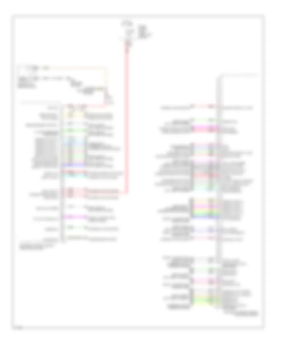
BODY CONTROL MODULES
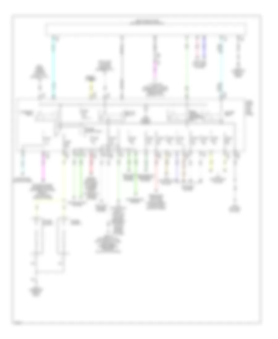
Body Control Modules Wiring Diagram (1 of 2) for Infiniti Q50 Hybrid Sport 2014
List of elements for Body Control Modules Wiring Diagram (1 of 2) for Infiniti Q50 Hybrid Sport 2014:
- 36c
- A/t shift selct pwr sply
- Air conditioning system
- Bcm (body control module) (right end of dash)
- Blwr fan rly cont
- Can-h
- Can-l
- Combi sw input 1
- Combi sw input 2
- Combi sw input 3
- Combi sw input 4
- Combi sw input 5
- Combi sw output 1
- Combi sw output 2
- Combi sw output 3
- Combi sw output 4
- Combi sw output 5
- Comm line
- Computer data lines system
- Defogger system
- Detent sw
- Dimmer
- Dongle link
- Door locks & anti-theft systems
- Drv dr req sw
- Drv dr sw
- Drv dr unlk sens
- Extend strge fuse sw
- Exterior lights & mirrors systems
- Exterior lights system
- Fuse 5a
- Fuse block (j/b) (left kick panel)
- Hazard sw
- Headlights system
- Headlights, exterior lights & interior lights systems
- Hot at all times
- I-key warn buzzer
- Ign rly (f/b) cont
- Ign rly (ipdm e/r) cont
- Inside key ant (trunk) +
- Inside key ant (trunk) -
- Interior lights system
- Kyls ent receiver rear (comm)
- M13
- M133
- M14
- M15
- M155
- M93 (left end of dash)
- M95
- One touch unlk dr
- One touch unlk pass
- Optical sens
- Outs hd lp cont
- P/n position
- Pass dr req sw
- Pass dr sw
- Pnk
- Power distribution system
- Power windows system
- Push btn ign sw ill pwr
- Push sw
- Push switch
- Push-button ignition switch
- Rain sensor
- Receiver (rear) pwr sply
- Receiver/sens gnd
- Red
- Red red
- Rr bmpr ant +
- Rr bmpr ant -
- Rr lh dr sw
- Rr rh dr sw
- Rr window def rly cont
- Security ind lp cont
- Sens pwr sply
- Starting/charging system
- Step lp cont
- Stop lp sw
- Stop lp sw 2
- Strt rly cont
- Tan
- Tr lid op cancel sw
- Tr lid opn req sw
- Tr lid opnr sw
- Tr room lp cont
- Tr room lp sw
- Transmissions system
- Trunk lid opn
- Trunk, tailgate, fuel doors system
- Turn sig lh output (side, rear)
- Turn sig rh output (side, rear)
- Wiper/washer system
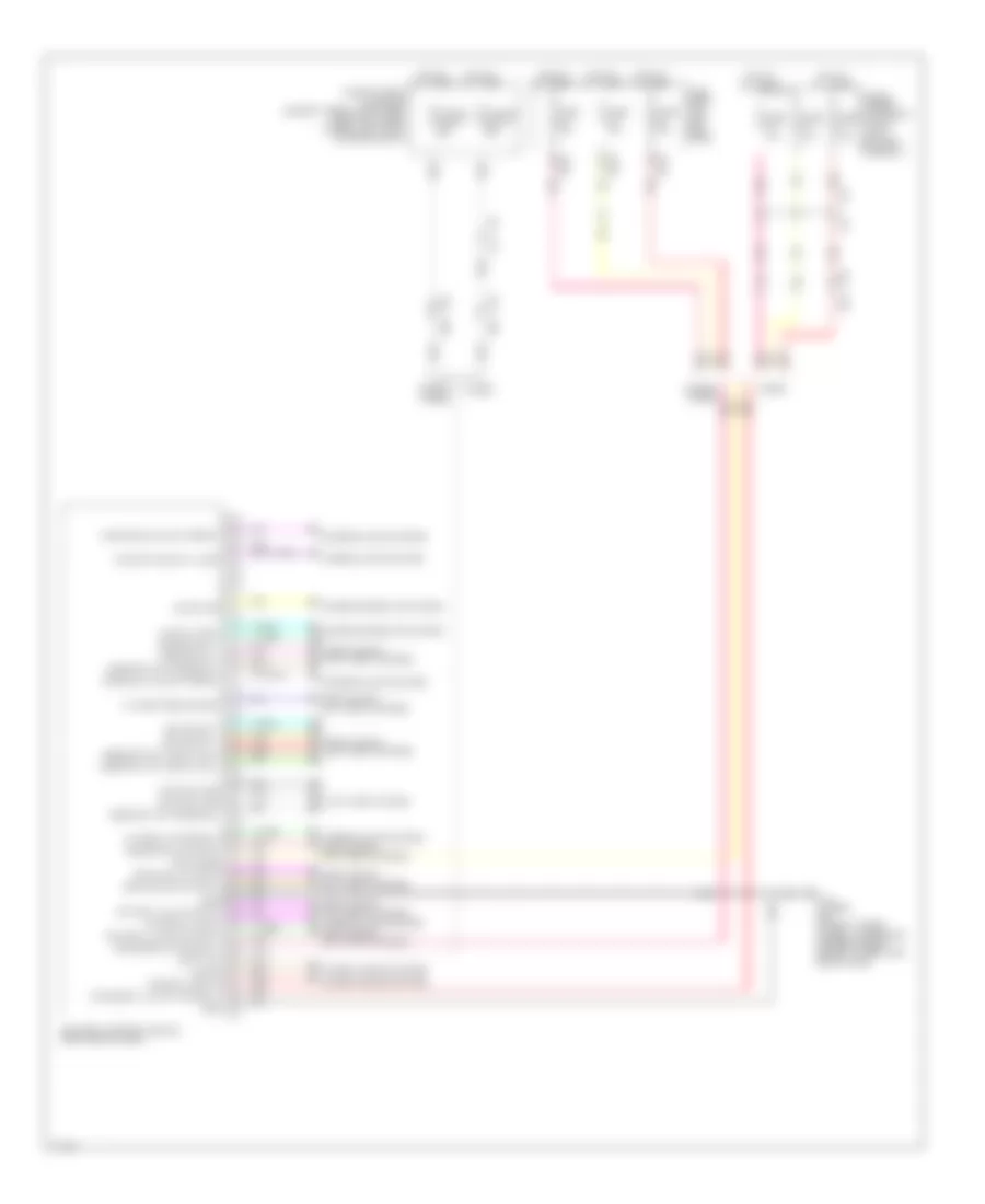
Body Control Modules Wiring Diagram (2 of 2) for Infiniti Q50 Hybrid Sport 2014
List of elements for Body Control Modules Wiring Diagram (2 of 2) for Infiniti Q50 Hybrid Sport 2014:
- 13b
- 14c
- Acc rly cont
- Acc/on ind
- Anti-theft system
- B18
- B41
- Bat (fuse)
- Batt (f/l)
- Bcm (body control module) (right end of dash)
- Door locks & anti-theft systems
- Door locks & anti-theft systems interior lights system door locks & anti-theft systems
- Drv dr ant +
- Drv dr ant -
- E25
- Except hybrid
- Exterior lights system
- Fr doors fl lid act pwr sply
- Frt dr fl lid lk output
- Frt dr fl lid unlk output
- Fuse & fusible link block (except hybrid: on battery positive (+) post) (hybrid: left front of engine compt)
- Fuse & fusible link block 1 (top of li-ion battery assembly)
- Fuse 10a
- Fuse 15a
- Fuse block (j/b) (left kick panel)
- Fusible link m 40a
- Fusible link t 40a
- Gnd
- Hot at all times
- Hybrid
- Ign on
- Insde key ant (console) +
- Insde key ant (console) -
- Insde key ant (instr lwr) +
- Insde key ant (instr lwr) -
- Int room lp cont
- Int room lp pwr sply
- Interior lights system
- Interior lights system door locks & anti-theft systems
- Kyls ent recive comm
- M111 (hybrid) m93 (except hybrid) (hybrid: lower right center of dash) (except hybrid: left end of dash)
- M132
- M133
- M16
- M17
- M19
- M40
- Nats ant amp
- Pass dr ant +
- Pass dr ant -
- Pass dr unlk output
- Pnk
- Power distribution system
- Power windows system
- Push btn ign sw ill gnd
- Pwr sply (batt)
- Red
- Rr doors act pwr sply
- Rr rl dr lk output
- Rr rl dr unlk output
- T25
- T25 b41
- Tan
- Turn sig lh output (front)
- Turn sig rh output (front)
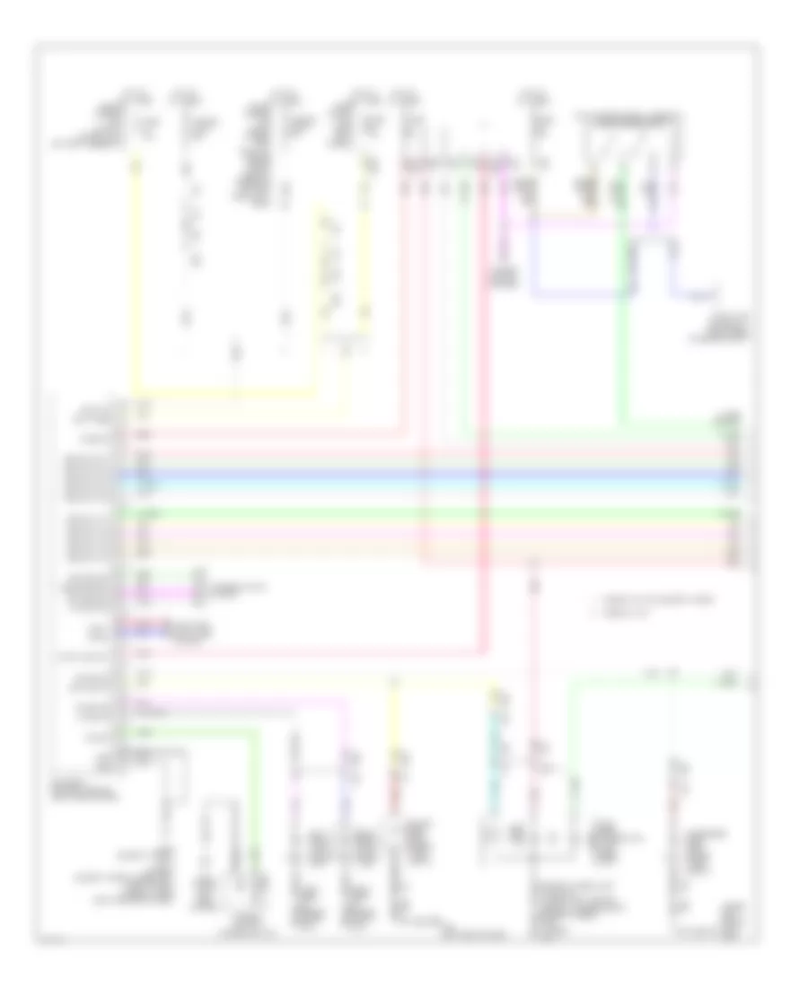
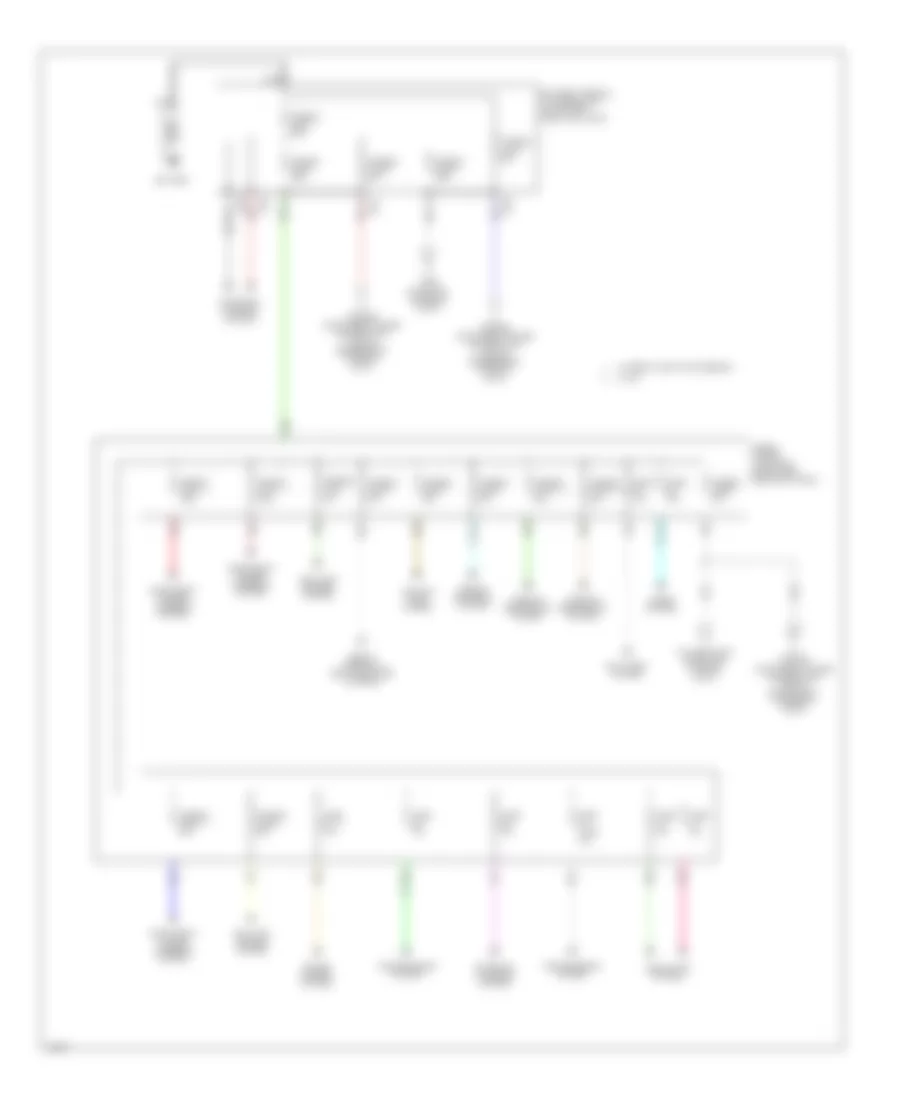
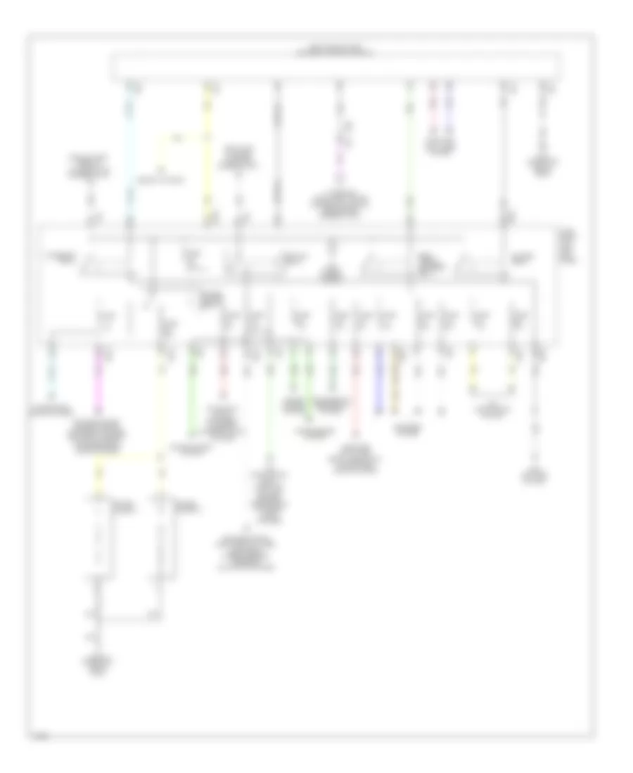
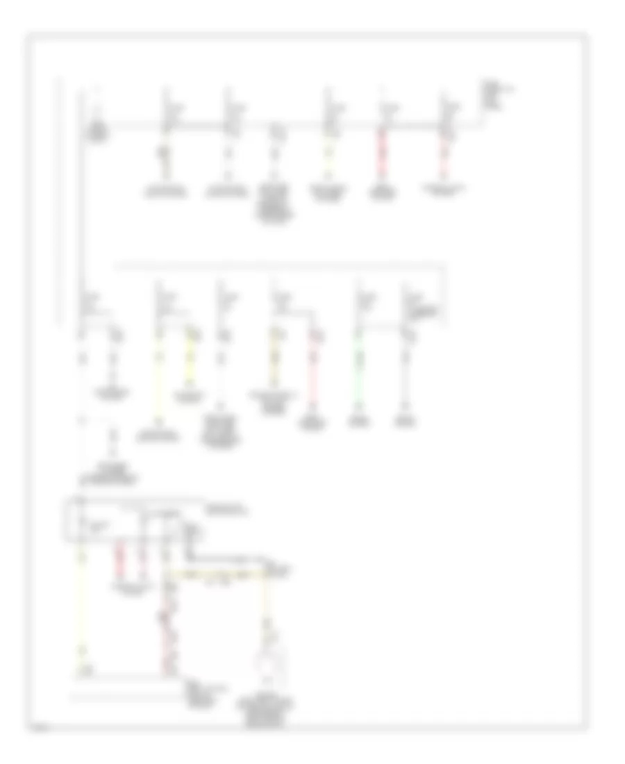
COMPUTER DATA LINES
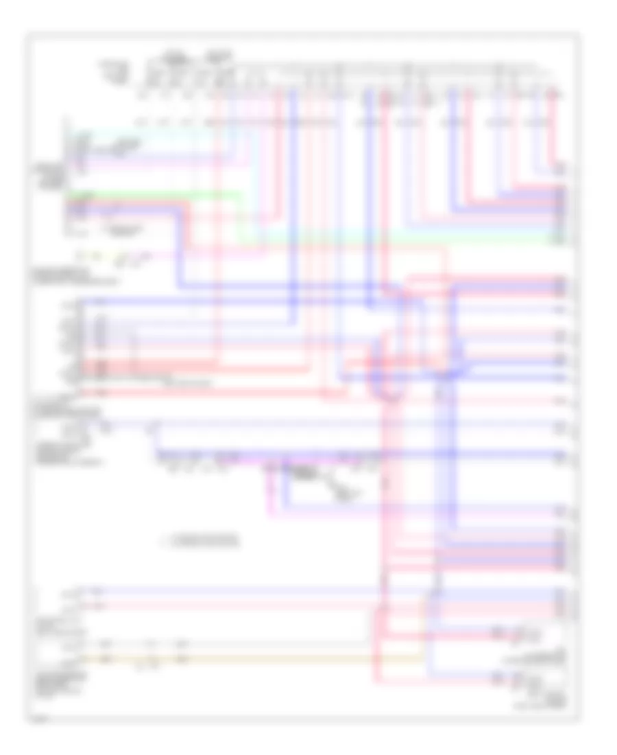
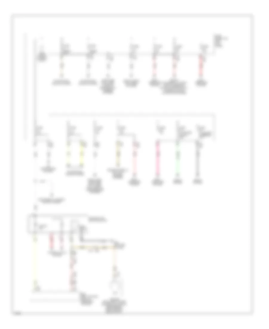
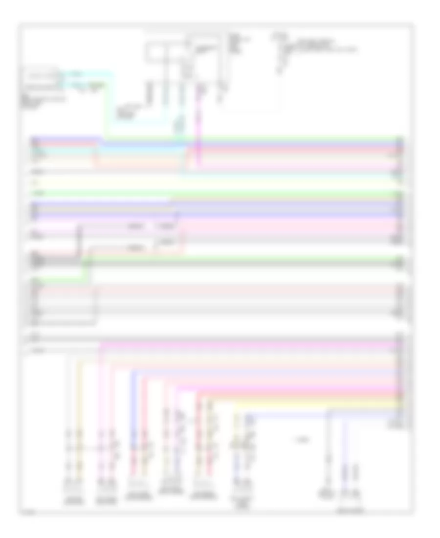
Computer Data Lines Wiring Diagram, Except Hybrid (1 of 3) for Infiniti Q50 Hybrid Sport 2014
List of elements for Computer Data Lines Wiring Diagram, Except Hybrid (1 of 3) for Infiniti Q50 Hybrid Sport 2014:
- (left end of dash) m93
- 10c
- 13c
- 20c
- 21c
- 22c m133
- 23c
- 29c
- 30c
- 37c
- 3c m133
- 3f e65
- 4h b39
- 7f e65
- 8h b39
- Afs control unit (w/ icc) (right end of dash)
- Auto anti-dazzling inside mirror (high beam assist control module) (w/ icc)
- B104 (left kick panel)
- B18
- B62
- Batt
- Body control module (right end of dash)
- Can gateway (w/ around view monitor) (lower left end of dash)
- Can-h
- Can-l
- Can2-h
- Can2-l
- Can3-h
- Can3-l
- Data link connector (lower left side of dash)
- E25
- E26
- E64
- E65
- Fuse 10a
- Fuse 5a
- Fuse block (j/b) (left kick panel)
- Gnd
- Hot at all times
- Hot in on or start
- Ign
- M14
- M19
- M22
- M40
- M74
- M81
- M93 (left end of dash)
- Occupant detection system control unit (under front passenger's seat)
- Pnk
- Red
- Shield
- Steering angle main control module (left end of steering rack assembly)
- Tcu (w/ telematics) (lower center of dash)
- W/ around view monitor
- W/o around view monitor
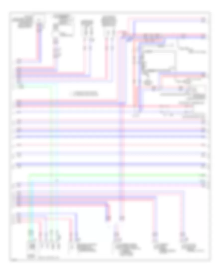
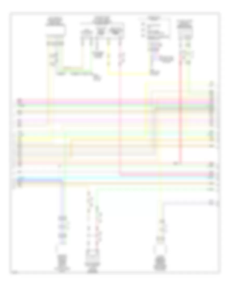
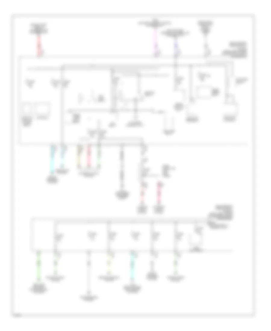
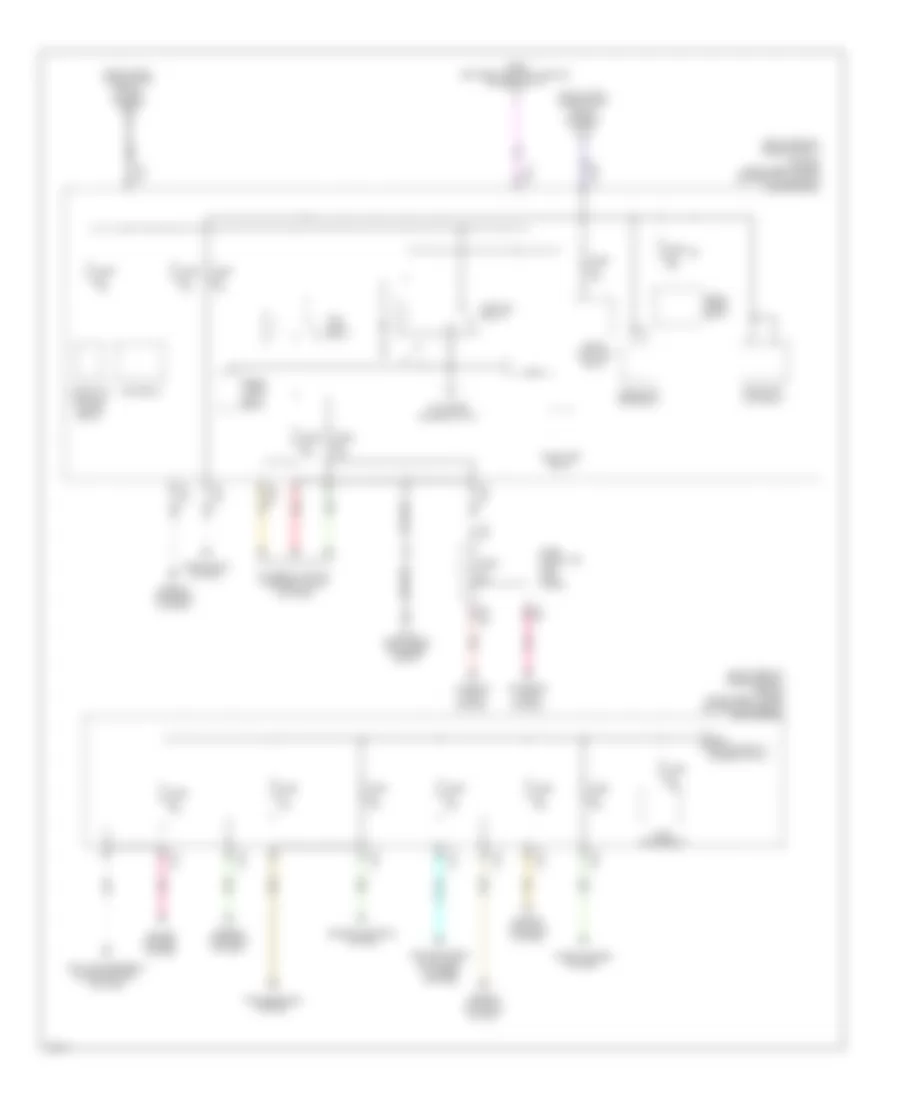
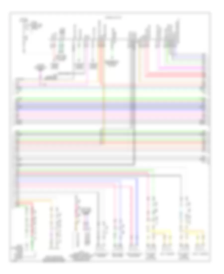
Computer Data Lines Wiring Diagram, Except Hybrid (2 of 3) for Infiniti Q50 Hybrid Sport 2014
List of elements for Computer Data Lines Wiring Diagram, Except Hybrid (2 of 3) for Infiniti Q50 Hybrid Sport 2014:
- (left "c" pillar) w/ icc b105
- (left rear of engine compt) abs actuator & electric unit (control unit)
- (on transmission) a/t assembly
- (under right end of dash) ecm
- A/c auto amplifier (behind integral switch)
- Air bag diagnosis sensor unit (under rear of center console)
- B104 (left kick panel)
- B106 (right kick panel)
- B12
- B19
- B37
- B600
- B62
- B72
- Can-h
- Can-l
- Comm h
- Comm l
- Comm line
- Cpu
- Display control unit
- Driver seat control unit
- Driver side front seat
- Driver side pre-cash seat belt control unit (awd models) (under driver seat)
- E10
- E121
- F12
- Integral switch
- Ipdm e/r (intelligent power distribution module engine room) (right rear of engine compt)
- Joint connector
- M100
- M22
- M37
- M71
- M88
- Nca
- Pnk
- Red
- Shield
- Steering angle sensor (upper steering column)
- Steering force control module (w/ direct adaptive steering) (lower right end of dash)
- Transmission control module (tcm)
- W/ around view monitor
- W/ icc
- W/o around view monitor
- W/o icc
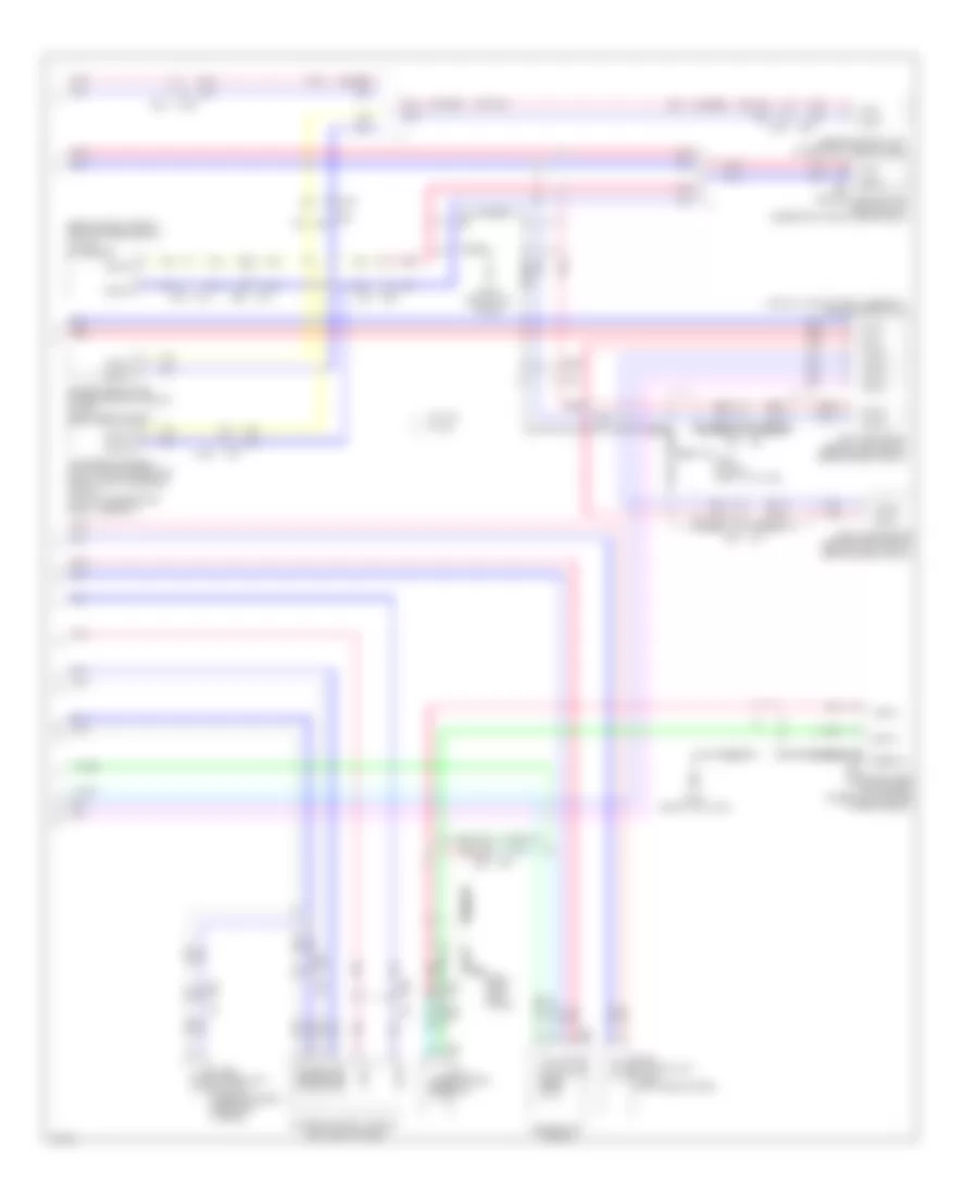
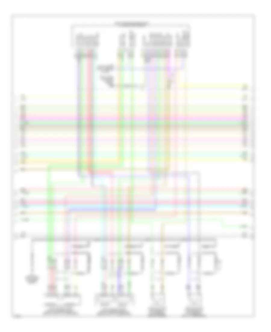
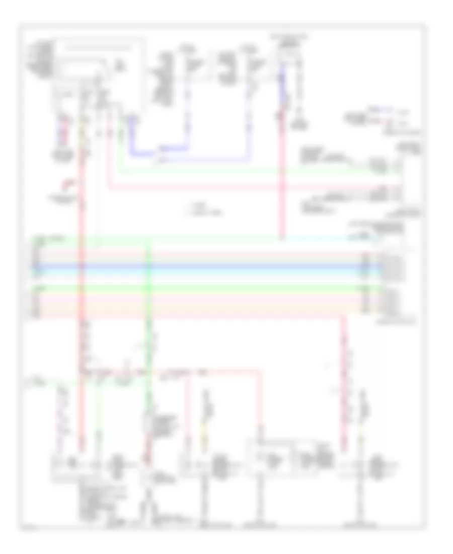
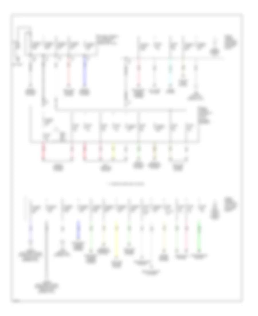
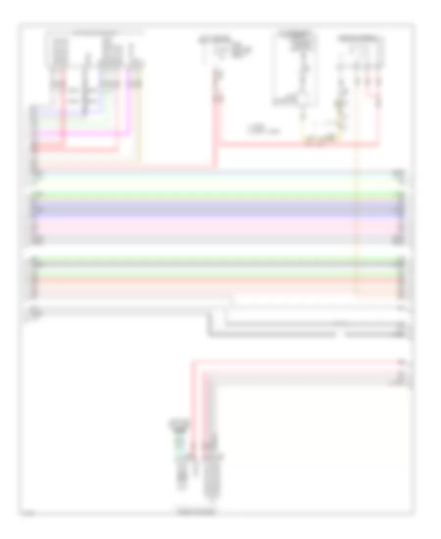
Computer Data Lines Wiring Diagram, Except Hybrid (3 of 3) for Infiniti Q50 Hybrid Sport 2014
List of elements for Computer Data Lines Wiring Diagram, Except Hybrid (3 of 3) for Infiniti Q50 Hybrid Sport 2014:
- (behind right side of front bumper fascia) (w/ icc) icc sensor
- (or red)
- (top of li-ion battery assembly) adas control unit
- Accelerator pedal actuator/accelerator pedal position sensor (w/ icc) (top of accelerator pedal assembly)
- Around view monitor control unit (under right end of rear shelf)
- Av control unit
- Awd control unit (awd) (left side of dash)
- B105 (w/ icc) (left "c" pillar)
- B106 (right kick panel)
- B107 (right "b" pillar)
- B50
- B52
- B55
- B62
- B62 m22
- B87
- Bose amplifier (if equipped) (under left center of rear shelf)
- Can-h
- Can-l
- Chassis control module (left end of dash)
- Combination meter
- Comm h
- Comm l
- Comm sig h
- Comm sig l
- Comm-h
- Comm-l
- Driver assistance buzzer control module (w/ icc) (right side of dash)
- E14
- E25
- E47
- E76
- Lane camera unit (w/o icc) (base of inside rearview mirror)
- Left side radar (behind left end of rear bumper fascia)
- M125
- M155
- M22
- M39
- M40
- M58
- M67
- M75
- M95
- Pnk
- Red
- Right side radar (behind right end of rear bumper fascia)
- Shield
- Sonar control unit (lower right side of dash)
- W/ icc
- W/o icc
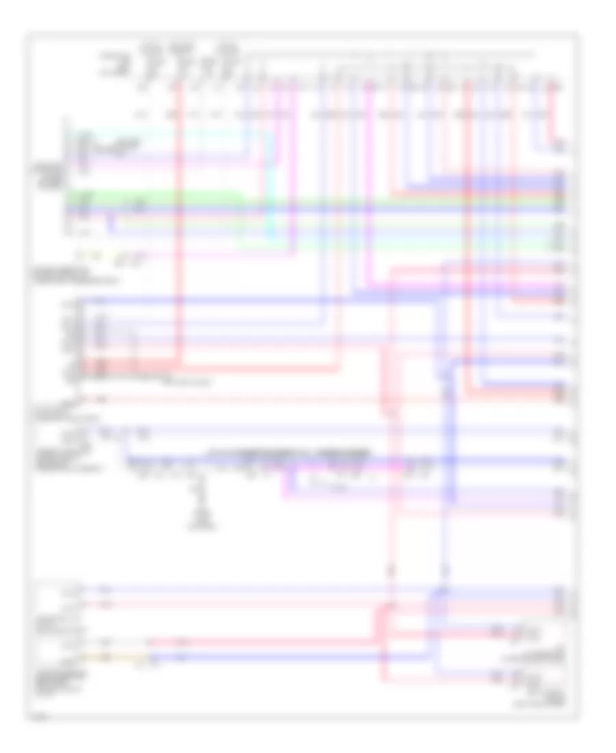
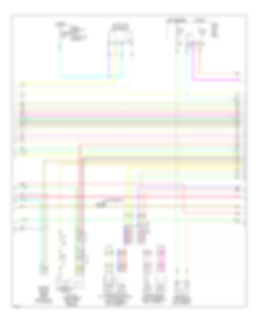
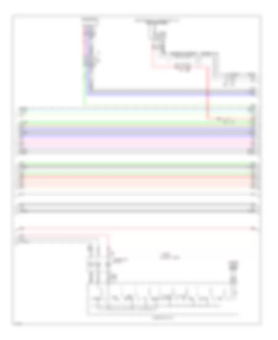
Computer Data Lines Wiring Diagram, Hybrid (1 of 3) for Infiniti Q50 Hybrid Sport 2014
List of elements for Computer Data Lines Wiring Diagram, Hybrid (1 of 3) for Infiniti Q50 Hybrid Sport 2014:
- (left end of dash) m93
- (lower left side of dash)
- 10c
- 12c
- 13c
- 20c
- 23c
- 29c
- 2e e64
- 30c
- 37c
- 6f e65
- 8h b39
- Afs control unit (w/ icc) (right end of dash)
- Auto anti-dazzling inside mirror (high beam assist control module) (w/ icc)
- B104 (w/ icc) (left kick panel)
- B18
- B30
- B35
- B62
- Batt
- Body control module (right end of dash)
- Can gateway (lower left end of dash)
- Can-h
- Can-l
- Data link connector
- E25
- E26
- E65 5f
- Fuse 10a
- Fuse 5a
- Fuse block (j/b) (left kick panel)
- Gnd
- Hot at all times
- Hot in on or start
- Ign
- M133
- M133 2c
- M14
- M19
- M22
- M40
- M74
- M81
- M93 (left end of dash)
- Occupant detection system control unit (under front passenger's seat)
- Pnk
- Red
- Shield
- Steering angle main control module (left end of steering rack assembly)
- T27
- Tcu (w/ telematics) (lower center of dash)
- W/ icc
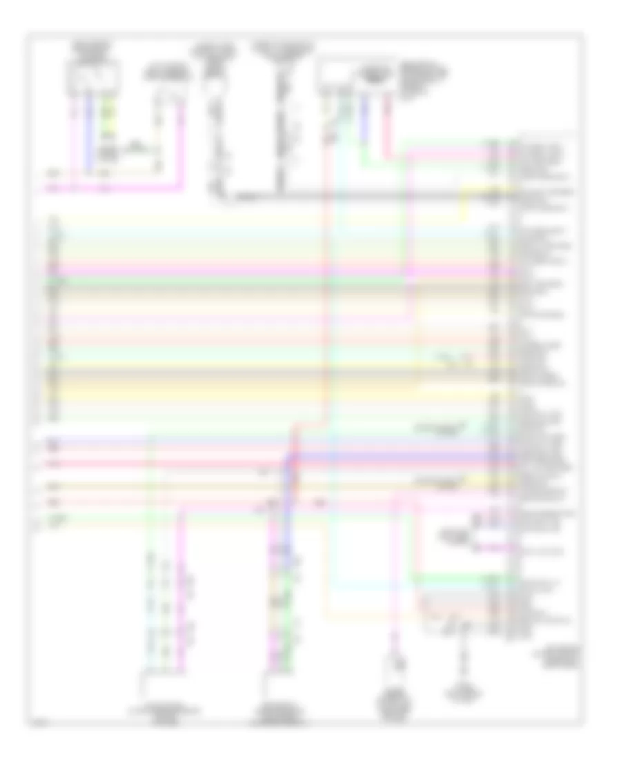
Computer Data Lines Wiring Diagram, Hybrid (2 of 3) for Infiniti Q50 Hybrid Sport 2014
List of elements for Computer Data Lines Wiring Diagram, Hybrid (2 of 3) for Infiniti Q50 Hybrid Sport 2014:
- (left rear of engine compt) abs actuator & electric unit (control unit)
- (on transmission) a/t assembly
- (right front of engine compt) ecm
- (top right side of li-ion battery assembly) hpcm
- A/c auto amplifier (behind integral switch)
- Air bag diagnosis sensor unit (under rear of center console)
- Approaching vehicle sound for pedestrians (vsp) control unit
- B104 (left kick panel)
- B12
- B15
- B18
- B19
- B29
- B600
- Can-h
- Can-l
- Comm h
- Comm l
- Cpu
- Display control unit
- Driver seat control unit
- Driver side front seat
- Driver side pre-cash seat belt control unit (w/ icc)
- E11
- E121
- E25
- Electrically- driven intelligent brake unit (under rear of center console)
- F10
- F11
- Integral switch
- Ipdm e/r (intelligent power distribution module engine room) (right rear of engine compt)
- Joint connector
- Li-ion battery
- Li-ion battery controller
- M100
- M155
- M155 m95
- M19
- M40
- M71
- M76
- M88
- M95
- Nca
- Pnk
- Red
- Shield
- Sonar control unit (w/ around view motor) (left side of dash)
- Steering force control module (lower right end of dash)
- Sub electric oil pump inverter (on transmission assembly)
- T28
- Traction motor inverter (right rear of engine compt)
- Transmission control module (tcm)
- W/ icc
- W/o icc
Computer Data Lines Wiring Diagram, Hybrid (3 of 3) for Infiniti Q50 Hybrid Sport 2014
List of elements for Computer Data Lines Wiring Diagram, Hybrid (3 of 3) for Infiniti Q50 Hybrid Sport 2014:
- (behind right side of front bumper fascia) (w/ icc) icc sensor
- (top of li-ion battery assembly) adas control unit
- Accelerator pedal actuator/accelerator pedal position sensor (w/ icc) (top of accelerator pedal assembly)
- Around view monitor control unit (under right end of rear shelf)
- Av control unit
- Awd control unit (awd) (left side of dash)
- B106 (right kick panel)
- B50
- B55
- B62
- B65 pnk
- B75
- Bose amplifier
- Can-h
- Can-l
- Chassis control module (left end of dash)
- Combination meter
- Comm h
- Comm l
- Comm sig h
- Comm sig l
- Comm-h
- Comm-l
- Driver assistance buzzer control module (w/ icc) (right side of dash)
- E14
- E25
- E76
- Lane camera unit (w/o icc) (base of inside rearview mirror)
- Left side radar (behind left end of rear bumper fascia)
- M125
- M155
- M19
- M22
- M22 b62
- M34 e47
- M40
- M58
- M67
- M75
- M95
- Pnk
- Red
- Right side radar (behind right end of rear bumper fascia)
- Shield
- Steering angle sensor (upper steering column)
- T21
- T43 (left center rear of luggage compt)
- T5 pnk
- T55
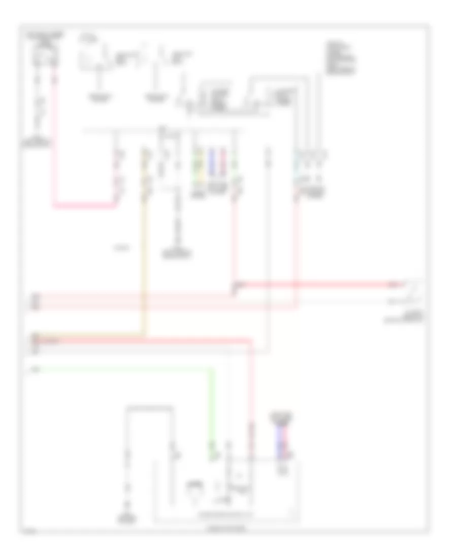
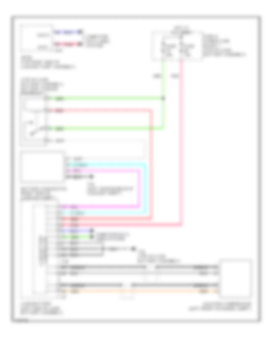
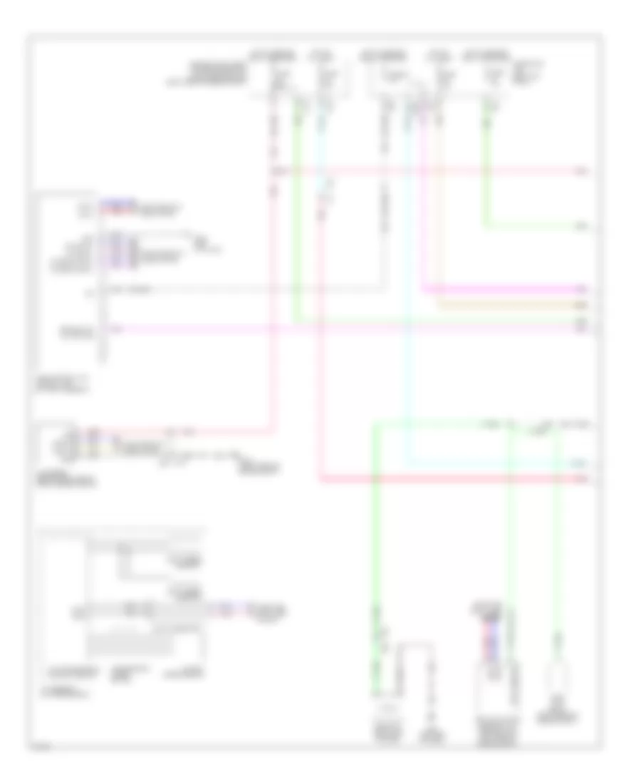
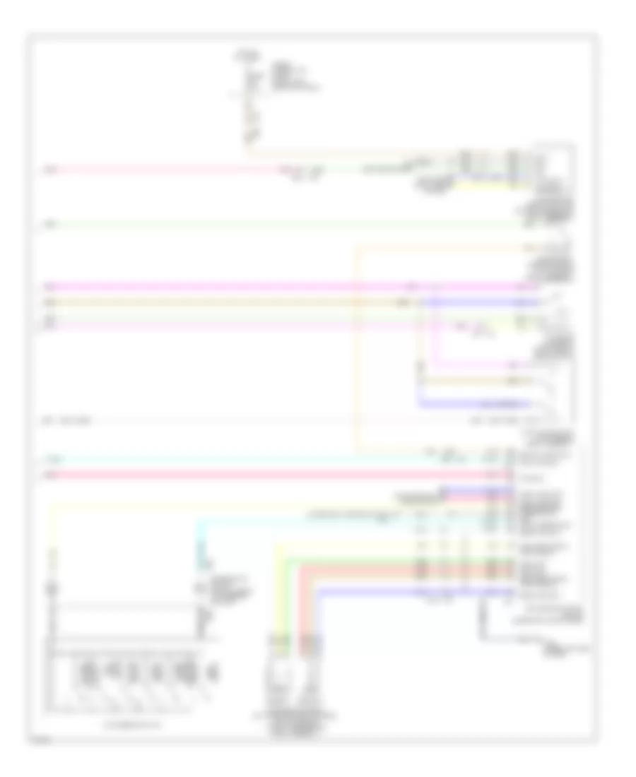
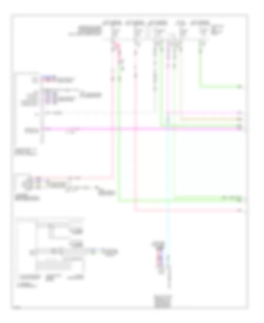
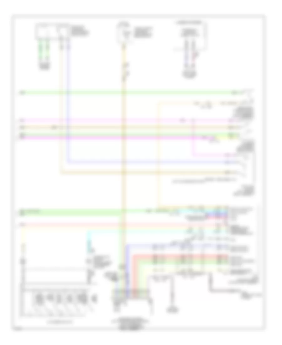
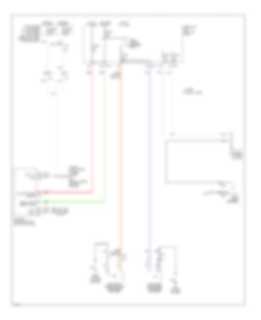
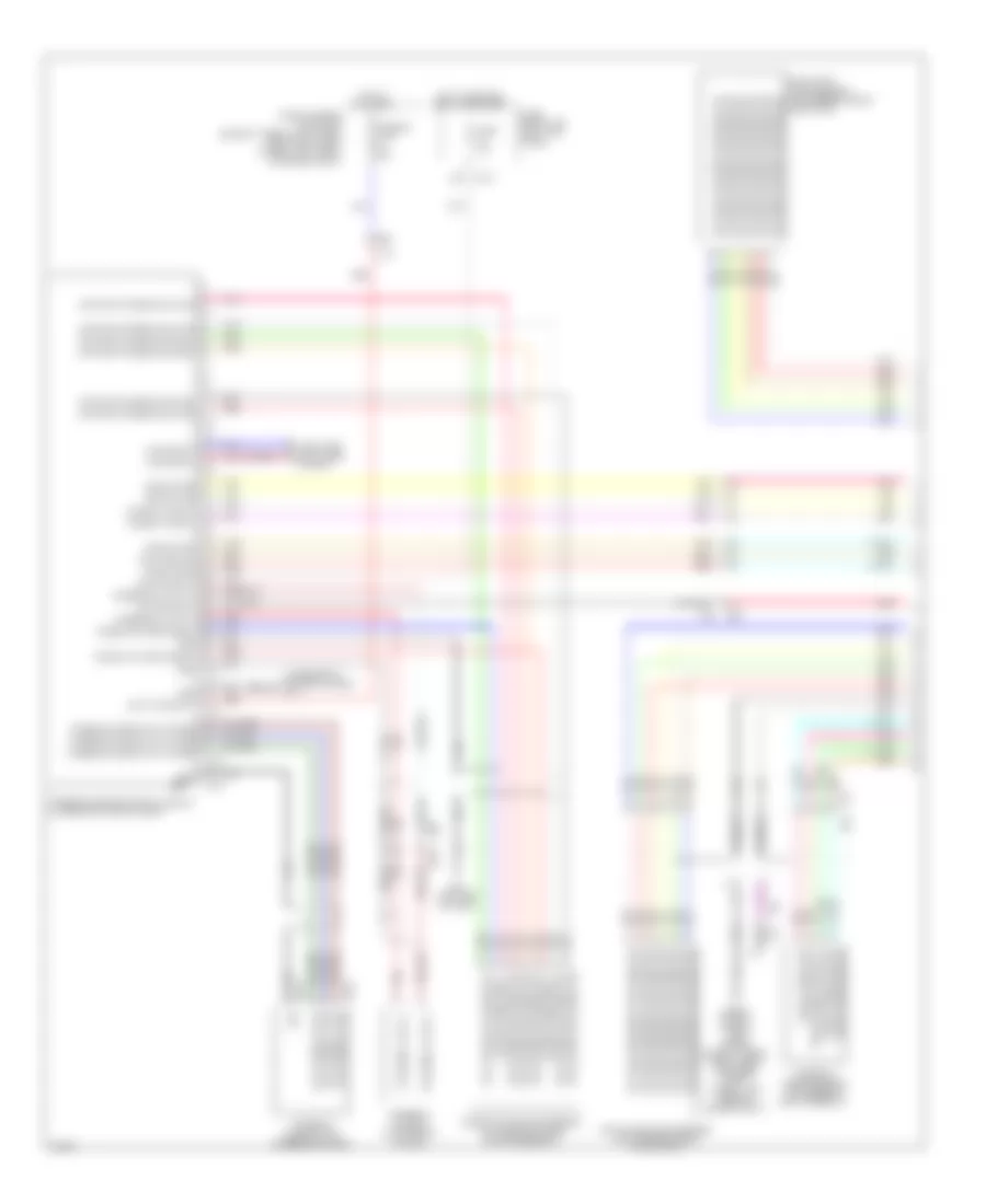
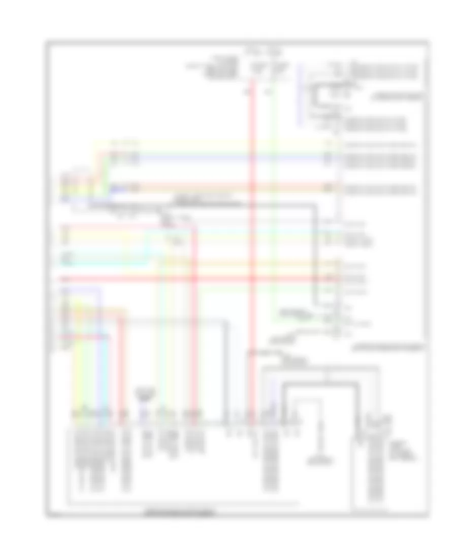
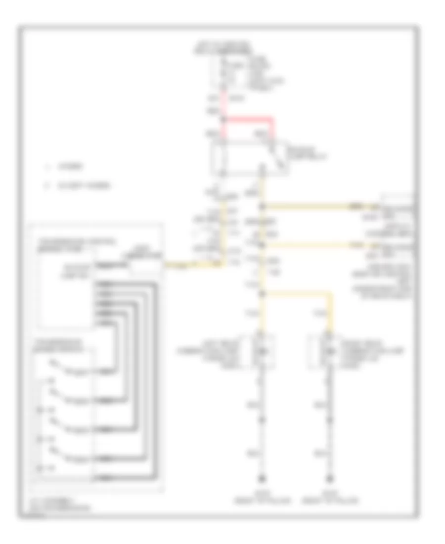
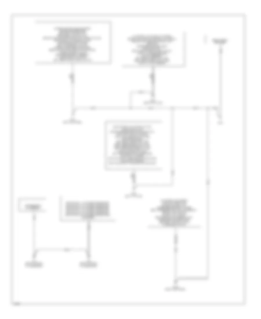
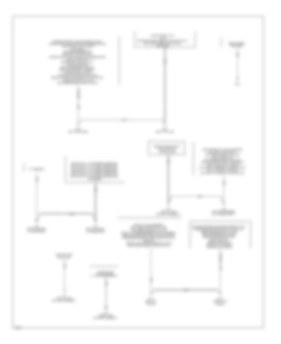
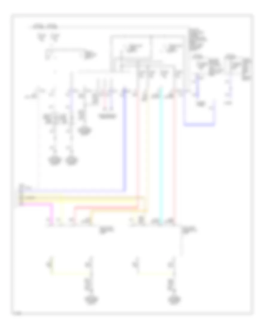
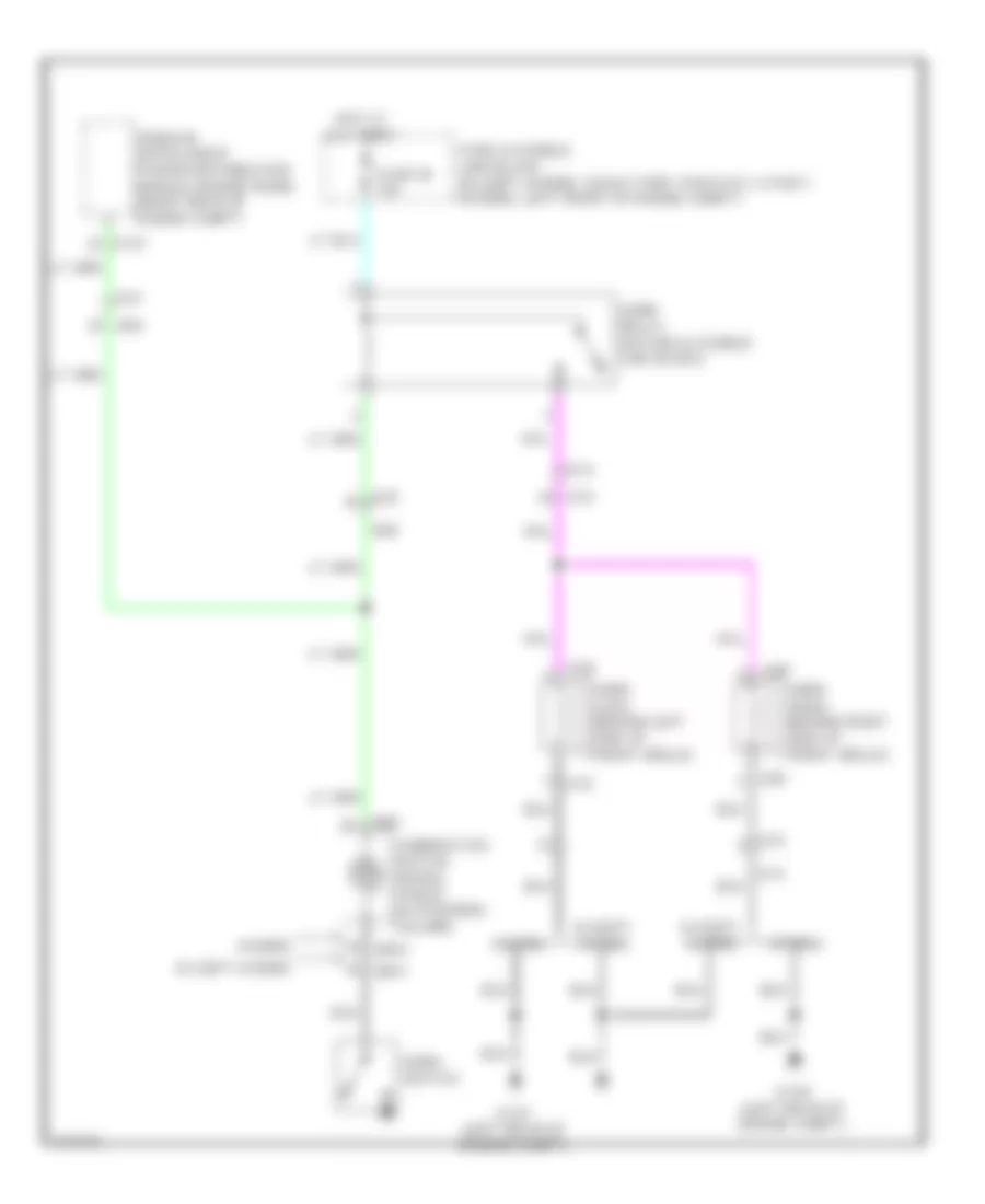
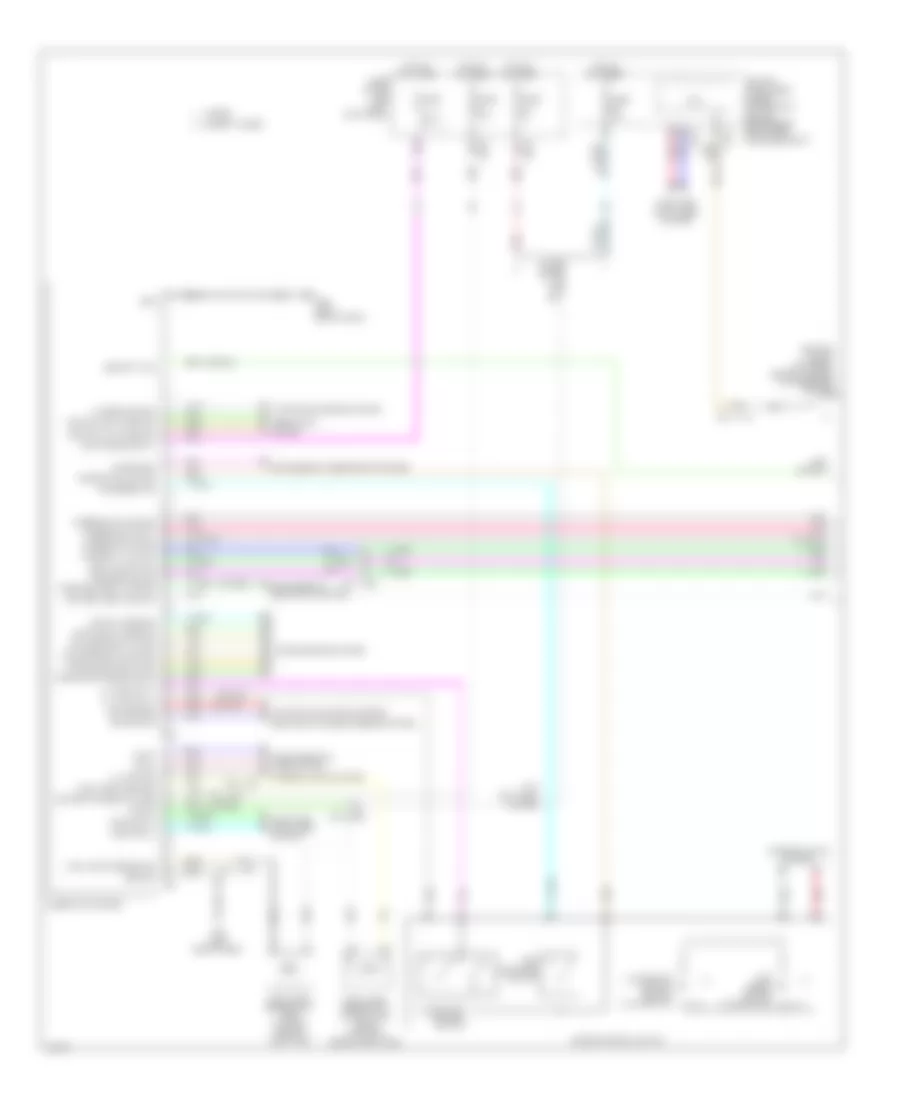
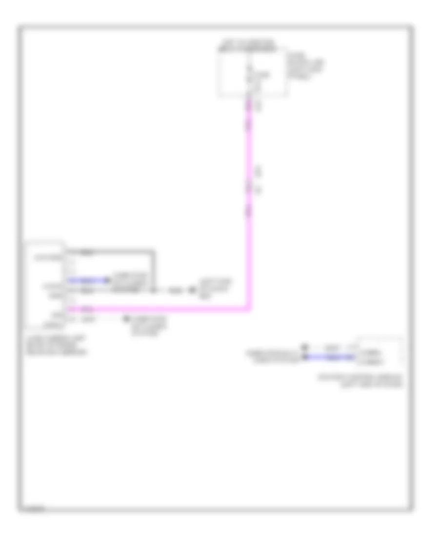
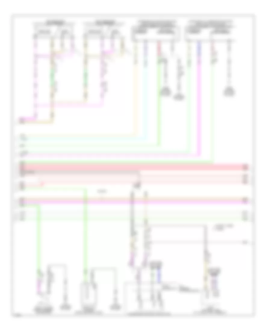
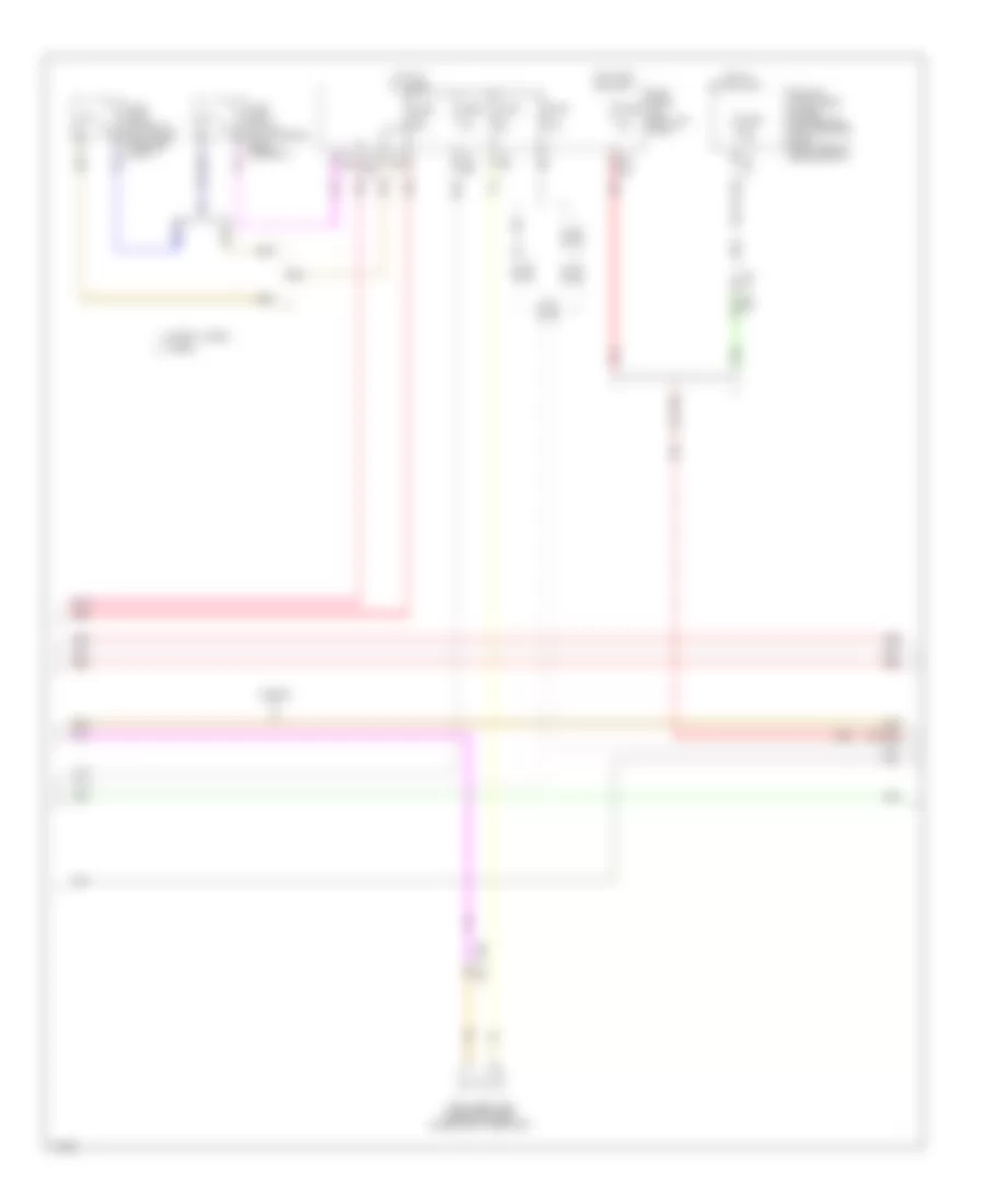
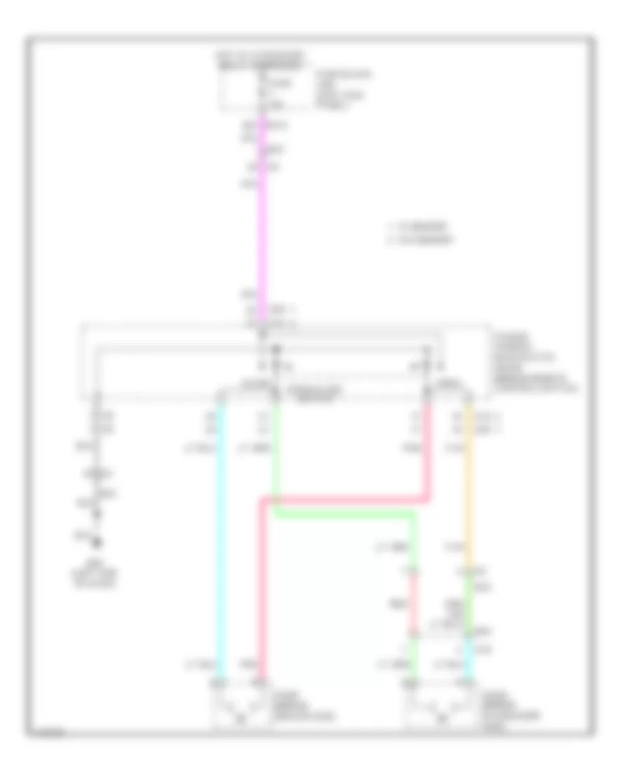
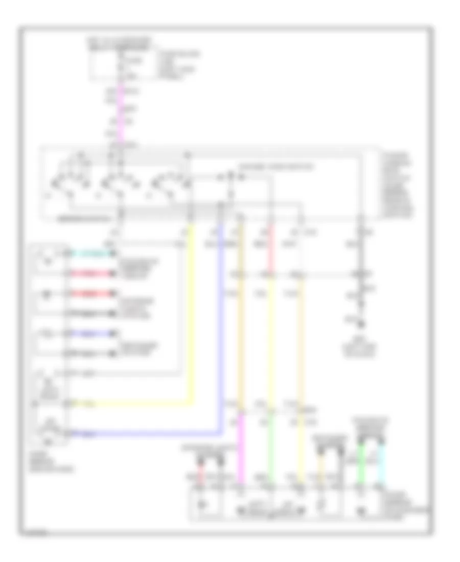
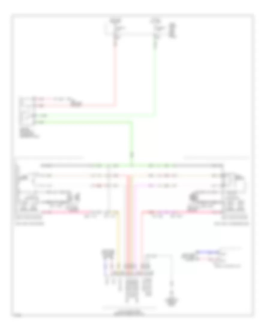
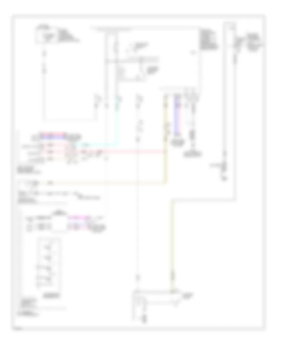
COOLING FAN
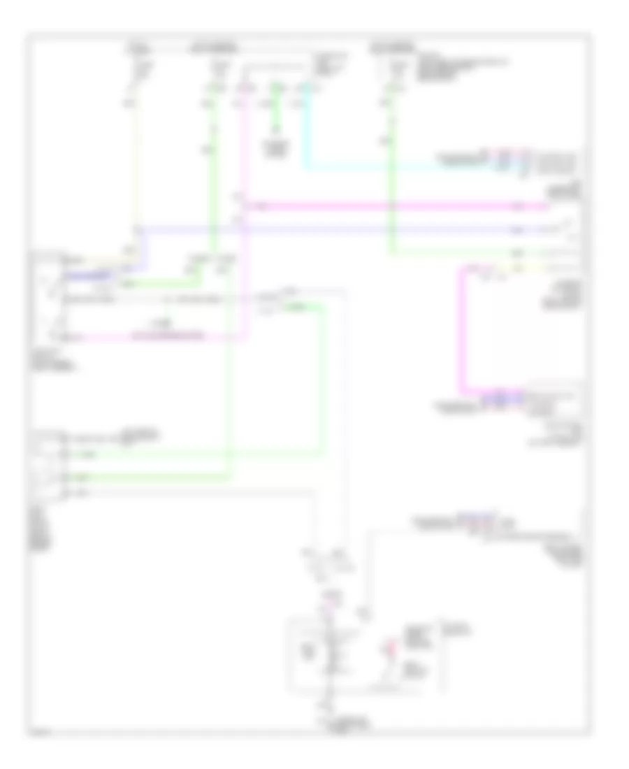
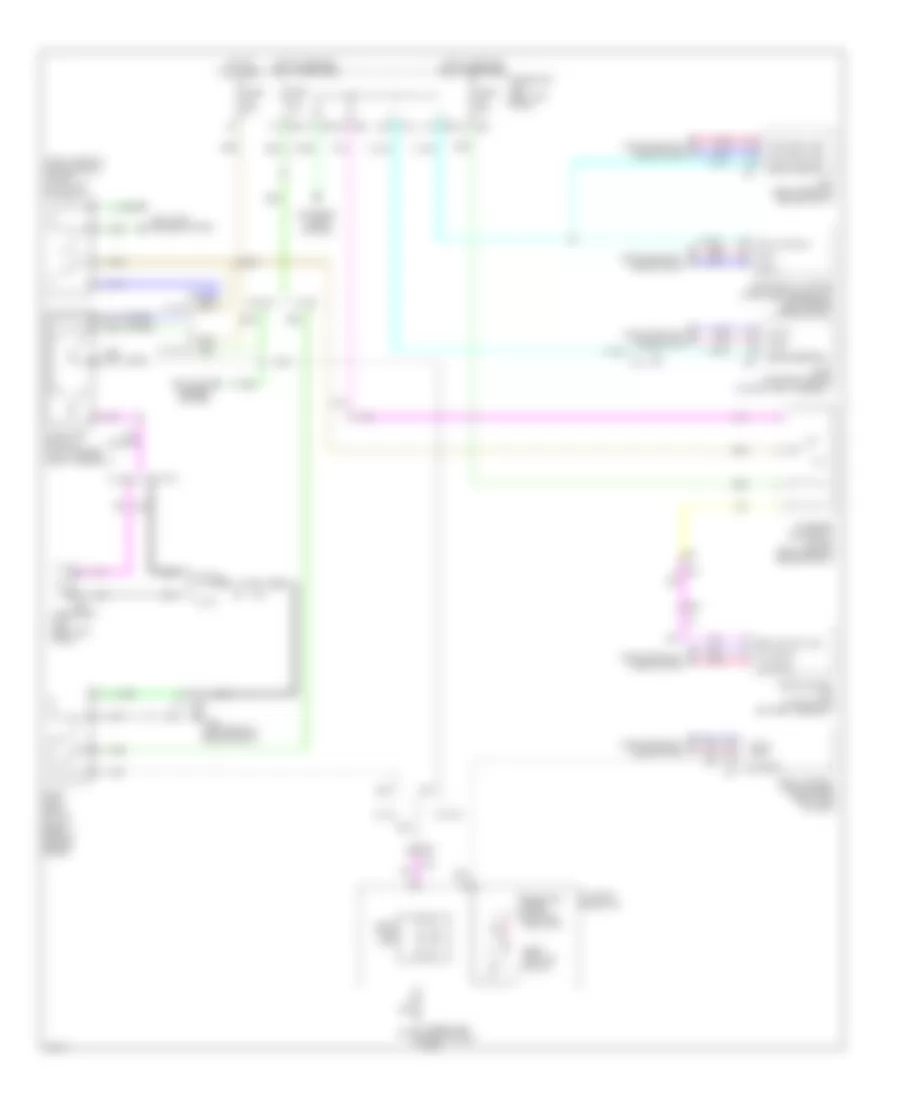
Cooling Fan Wiring Diagram for Infiniti Q50 Hybrid Sport 2014
List of elements for Cooling Fan Wiring Diagram for Infiniti Q50 Hybrid Sport 2014:
- (left rear of engine compt) (except hybrid) e137 (hybrid) e138
- (lower right center of dash) (except hybrid) m111 e134 (hybrid) (right rear of engine compt)
- (or pnk)
- A/c relay (except hybrid)
- Air conditioning system
- Can-high
- Can-low
- Computer data lines system
- Cooling fan control module (rear of cooling fan 1)
- Cooling fan motor 1 (behind left side of radiator)
- Cooling fan motor 2 (behind right side of radiator)
- Cooling fan relay 1 (in fuse & fusible link block)
- Cpu
- E10
- E11
- E118
- E120
- E121
- E123
- E126
- E134 (right rear of engine compt)
- E14
- E25
- E301
- E302
- E33
- E76
- E9 f11
- Ecm (engine control module) (except hybrid: under right end of dash) (hybrid: right front of engine compt)
- Engine controls system
- Engine coolant temp sens
- Engine coolant temperature sensor (rear of left cylinder bank)
- Except hybrid
- F10
- F12
- F3 f4
- Fuse & fusible link block (except hybrid: on battery positive (+) post) (hybrid: left front of engine compt)
- Fuse 10a
- Fusible link i 80a
- Fusible link o 50a
- Gnd
- Hot at all times
- Hybrid
- Ignition relay
- Ipdm e/r (intelligent power distribution module engine room) (right rear of engine compt)
- M37
- M40
- Nca
- Pnk
- Pwr sply
- Red
- Refrigerant press sns
- Refrigerant pressure sensor (left side of condenser assembly)
- Sens gnd
- Sens gnd (ect sens)
- Sens sply
- Tan
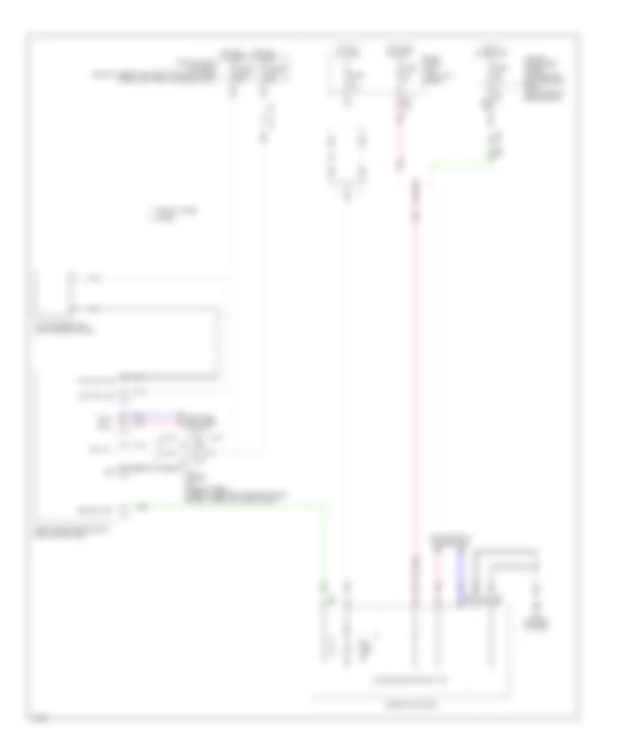
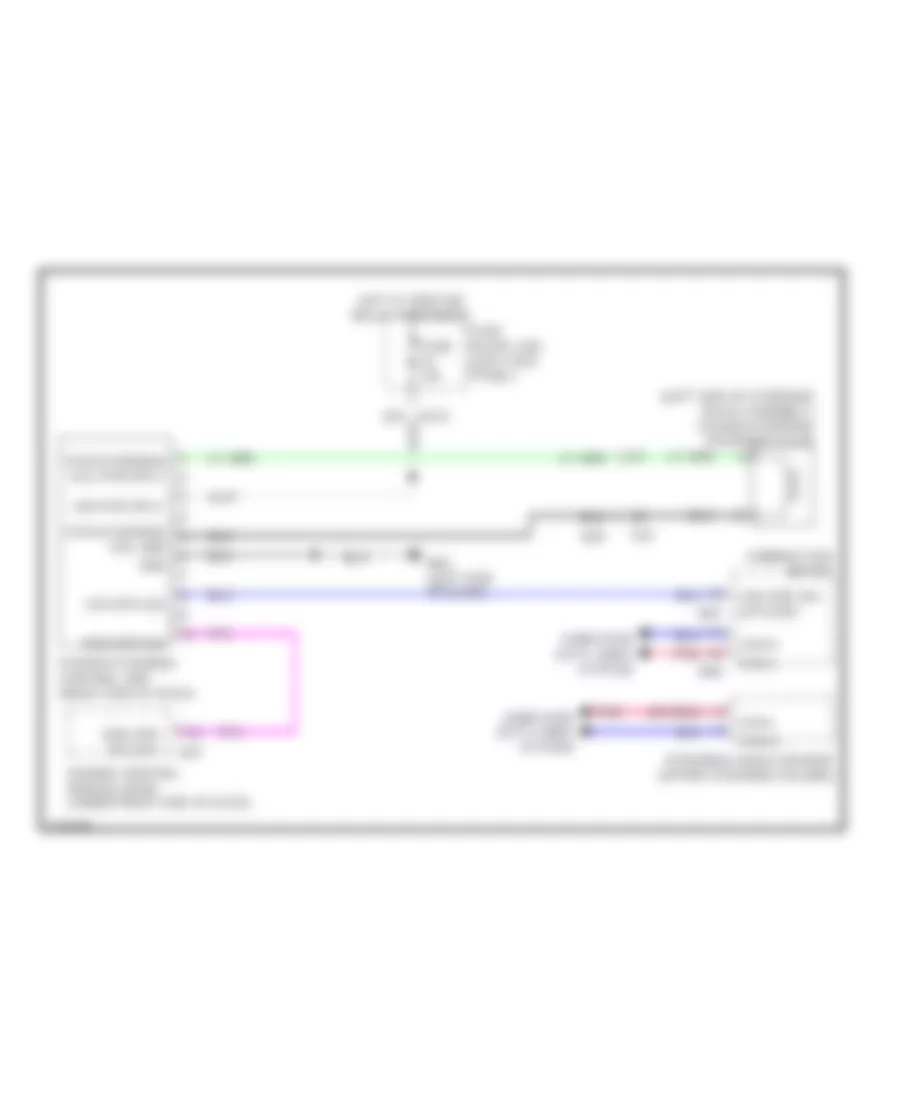
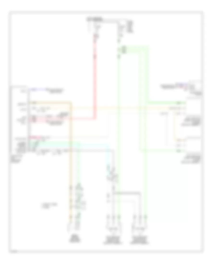
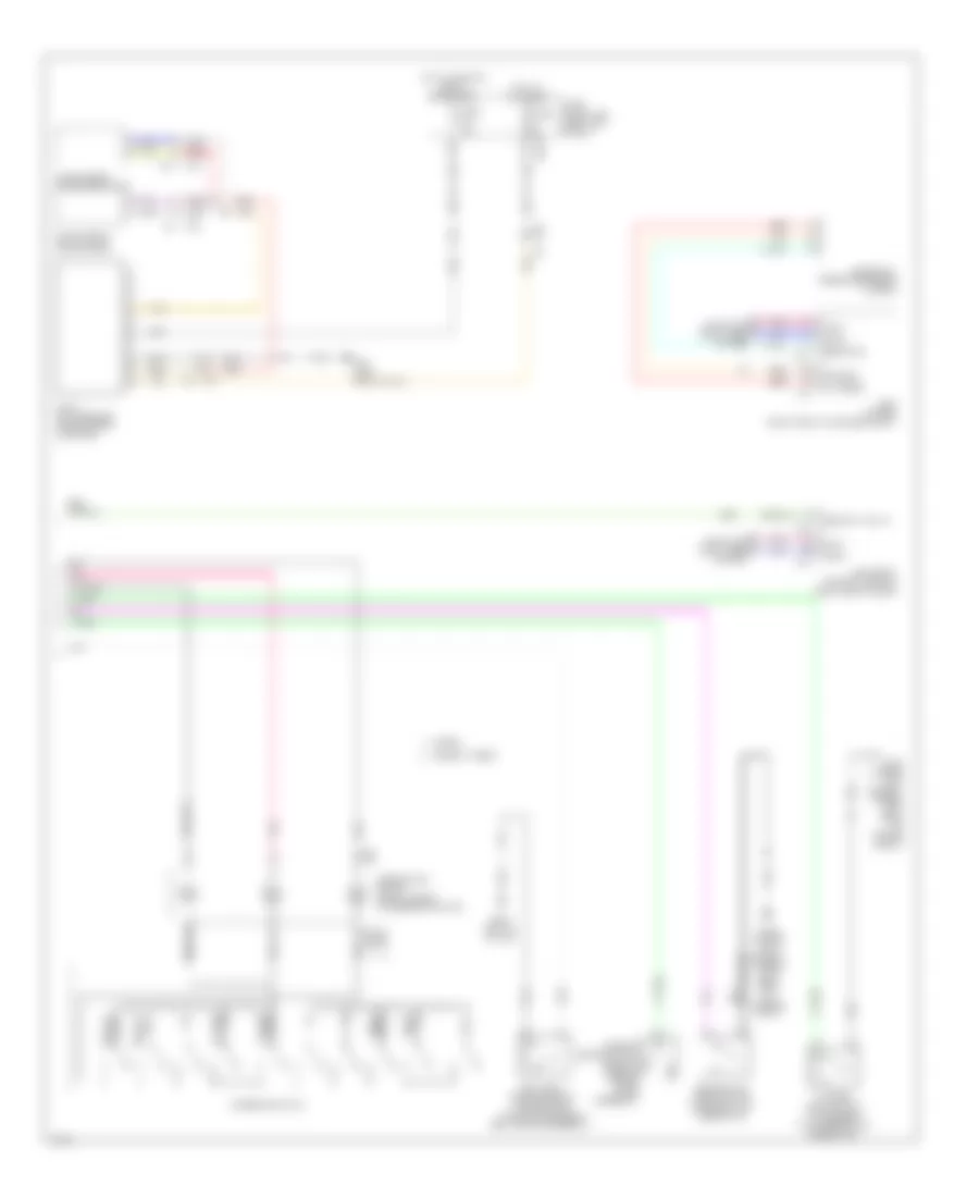
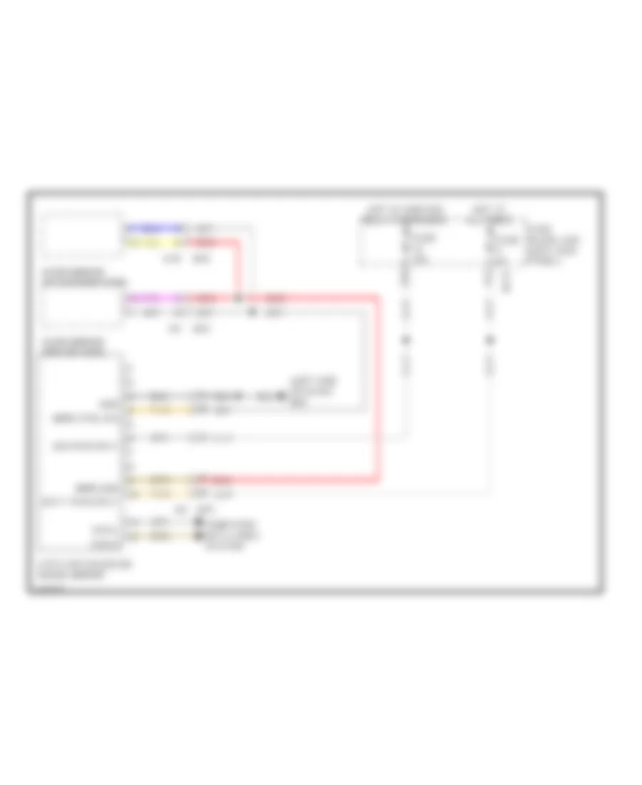
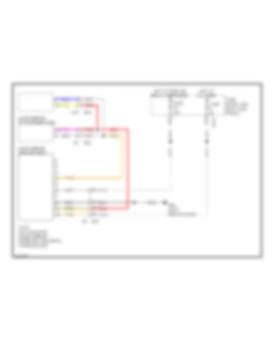
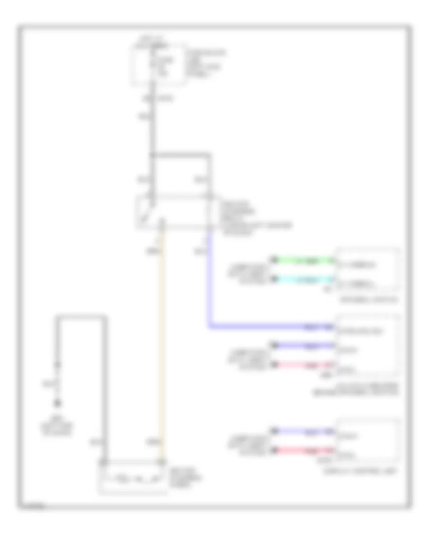
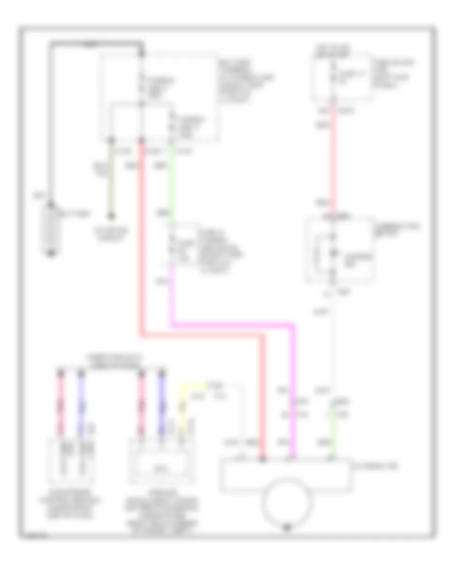
Hybrid Cooling Fan Wiring Diagram for Infiniti Q50 Hybrid Sport 2014
List of elements for Hybrid Cooling Fan Wiring Diagram for Infiniti Q50 Hybrid Sport 2014:
- (top of li-ion battery assembly) battery cooling fan relay
- B15
- Battery cooling fan (right side of luggage compt)
- Can h
- Can l
- Computer data lines system
- Electric compressor (left front of engine compt)
- Fuse & fusible link block 1 (top of li-ion battery assembly)
- Fuse 10a
- Fuse 20a
- Hot at all times
- Hpcm (top right side of li-ion battery assembly)
- Li-ion battery (left side of li-ion battery assembly)
- Li-ion battery controller
- Pnk
- Red
- Shield
- T22 (top of li-ion battery assembly)
- T28
- T43 (left center rear of luggage compt)
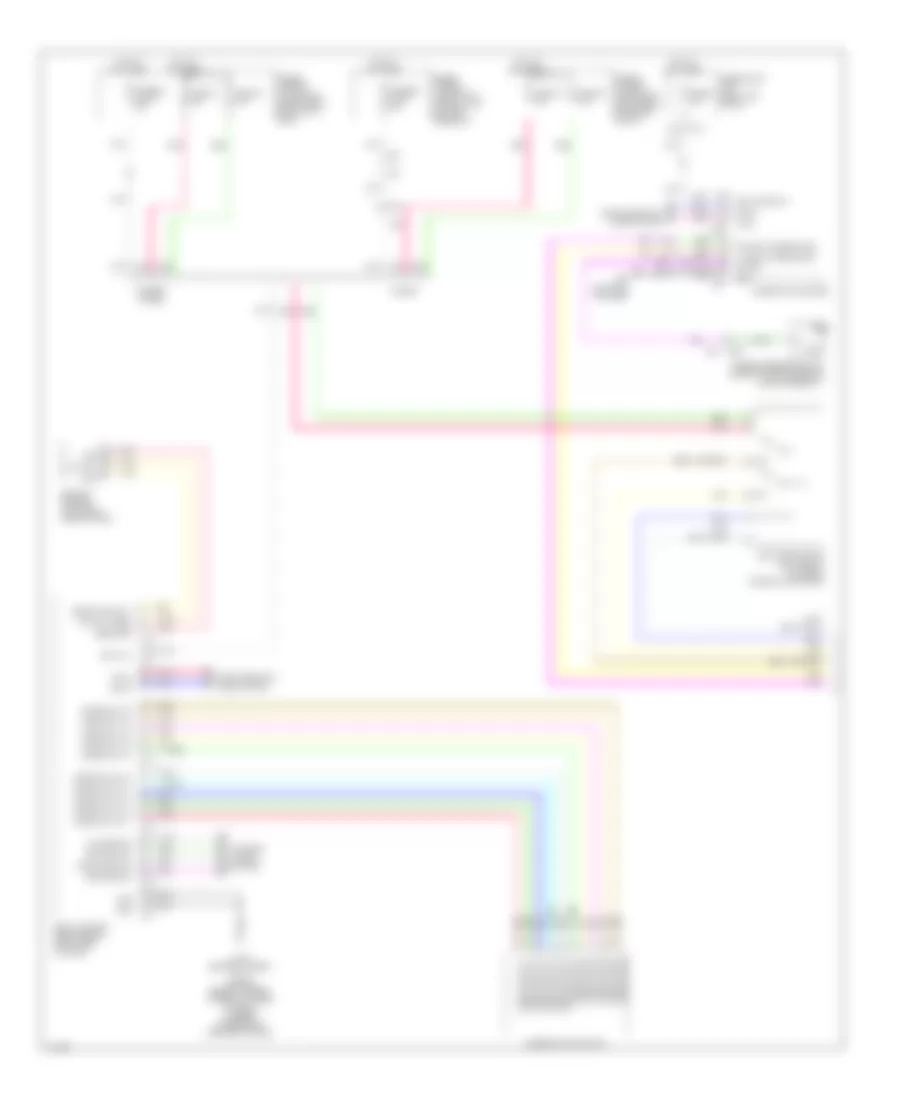
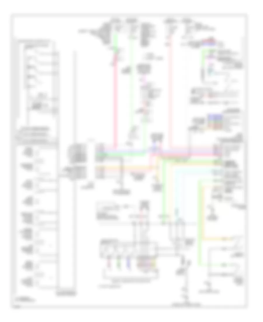
CRUISE CONTROL
Cruise Control Wiring Diagram, Except Hybrid (1 of 2) for Infiniti Q50 Hybrid Sport 2014
List of elements for Cruise Control Wiring Diagram, Except Hybrid (1 of 2) for Infiniti Q50 Hybrid Sport 2014:
- 11f
- 26c
- Accelerator pedal position sensor (behind accelerator pedal assembly)
- Acellerator pdl postn sens 1
- Acellerator pdl postn sens 2
- Ascd steering sw
- Brake pedal position switch (top of brake pedal assembly)
- Brk pdl postn sw
- Comm line can-h
- Comm line can-l
- Computer data lines system
- E10
- E120
- E123
- E124
- E25
- E64
- E65
- Ecm (engine control module) (under right end of dash)
- F12
- Fuse 10a
- Fuse 15a
- Fuse block (j/b) (left kick panel)
- Gnd
- Hot at all times
- Hot w/ ignition relay energized
- Ipdm e/r (intelligent power distribution module engine room) (right rear of engine compt)
- M111 (lower right center of dash)
- M125
- M133
- M37
- M40
- M67
- M93 (left end of dash)
- Mtr pwr sply (bank 1)
- Mtr pwr sply (bank 2)
- Mtr rly
- Nca
- Pnk
- Pwr sply
- Red
- Sens gnd
- Sens gnd (tps) (bank1)
- Sens gnd (tps) (bank2)
- Sens gnd(ascd steering sw)
- Sens pwr sply
- Sens pwr sply (tps (bank1))
- Sens pwr sply (tps (bank2))
- Sensor 1
- Sensor 2
- Stop lamp sw
- Stop lamp switch (top of brake pedal assembly)
- Tan
- Throttle control motor relay
- Throttle ctrl mtr (cls) (bank1)
- Throttle ctrl mtr (cls) (bank2)
- Throttle ctrl mtr (opn) (bank1)
- Throttle ctrl mtr (opn) (bank2)
- Throttle posi sens 1 (bank1)
- Throttle posi sens 1 (bank2)
- Throttle posi sens 2 (bank1)
- Throttle posi sens 2 (bank2)
Cruise Control Wiring Diagram, Except Hybrid (2 of 2) for Infiniti Q50 Hybrid Sport 2014
List of elements for Cruise Control Wiring Diagram, Except Hybrid (2 of 2) for Infiniti Q50 Hybrid Sport 2014:
- (on bank 1 throttle body assembly) electric throttle control actuator (bank 1)
- (on bank 2 throttle body assembly) electric throttle control actuator (bank 2)
- A/t assembly (on transmission)
- Accelerate/ resume switch
- Ascd steering switch
- Can-h
- Can-l
- Cancel switch
- Coast/ set switch
- Combination meter
- Combination switch (spiral cable) (in steering column)
- Computer data lines system
- Cruise ind & set ind
- Input speed sensor 1
- Input speed sensor 2
- Joint connector
- M111 (lower right center of dash)
- M301
- M58
- M87
- Main (on/ off) switch
- Nca
- Output speed sensor
- Pnk
- Red
- Sensor 1
- Sensor 2
- Tcm (transmission control module)
- Throttle control motor
- Throttle position sensor
- Transmission range switch
Cruise Control Wiring Diagram, Hybrid (1 of 2) for Infiniti Q50 Hybrid Sport 2014
List of elements for Cruise Control Wiring Diagram, Hybrid (1 of 2) for Infiniti Q50 Hybrid Sport 2014:
- 10f
- 11f
- Brake pedal position switch (top of brake pedal assembly)
- Brk pdl postn sw
- Comm line can-h
- Comm line can-l
- Computer data lines system
- E11
- E120
- E123
- E124
- E134 (right rear of engine compt)
- E64
- E65
- Ecm (engine control module) (right front of engine compt)
- F10
- F11
- Fuse 10a
- Fuse 15a
- Fuse block (j/b) (left kick panel)
- Gnd
- Hot at all times
- Hot w/ ignition relay energized
- Ipdm e/r (intelligent power distribution module engine room) (right rear of engine compt)
- Mtr pwr sply (bank1)
- Mtr pwr sply (bank2)
- Mtr rly
- Pnk
- Pwr sply
- Red
- Sens gnd (tps) (bank1)
- Sens gnd (tps) (bank2)
- Sens pwr sply (tps (bank1))
- Sens pwr sply (tps (bank2))
- Stop lamp sw
- Stop lamp switch (top of brake pedal assembly)
- Tan
- Throttle control motor relay
- Throttle ctrl mtr (cls) (bank1)
- Throttle ctrl mtr (cls) (bank2)
- Throttle ctrl mtr (opn) (bank1)
- Throttle ctrl mtr (opn) (bank2)
- Throttle posi sens 1 (bank1)
- Throttle posi sens 1 (bank2)
- Throttle posi sens 2 (bank1)
- Throttle posi sens 2 (bank2)
Cruise Control Wiring Diagram, Hybrid (2 of 2) for Infiniti Q50 Hybrid Sport 2014
List of elements for Cruise Control Wiring Diagram, Hybrid (2 of 2) for Infiniti Q50 Hybrid Sport 2014:
- (on bank 1 throttle body assembly) electric throttle control actuator (bank 1)
- (on bank 2 throttle body assembly) electric throttle control actuator (bank 2)
- A/t assembly (on transmission)
- Accelerator pedal position sensor (behind accelerator pedal assembly)
- Aps2
- Avcc
- Avcc2
- B105 (left "c" pillar)
- B14
- B15
- B18
- Can-h
- Can-l
- Combination meter
- Computer data
- Computer data lines system
- Cruise (lcd), set, cruise (y), ldp, speed limit ind
- E134 (right rear of engine compt)
- Gnd
- Gnd-a
- Gnd-a2
- Hpcm (top right side of li-ion battery assembly)
- Ign sig
- Input speed sensor 1
- Input speed sensor 2
- Joint connector
- Lines system
- M108 (upper left side of dash)
- M125
- M19
- M58
- M67
- Nca
- Output speed sensor
- Pnk
- Pwr sply
- Red
- Sens gnd acellerator pdl postn sens 2 sens gnd acellerator pdl postn sens 1
- Sens pwr sply
- Sensor 1
- Sensor 2
- Shield
- Tcm (transmission control module)
- Throttle control motor
- Throttle position sensor
- Transmission range switch
Intelligent Cruise Control Wiring Diagram, Except Hybrid (1 of 2) for Infiniti Q50 Hybrid Sport 2014
List of elements for Intelligent Cruise Control Wiring Diagram, Except Hybrid (1 of 2) for Infiniti Q50 Hybrid Sport 2014:
- 11f
- 26c
- A/t assembly (on transmission)
- Abs actuator & electric unit (control unit) (left rear of engine compt)
- Adas control unit (top of li-ion battery assembly)
- B105 (left "c" pillar)
- B38
- Brake hold rly drv sig
- Can-h
- Can-l
- Chassis comm-h
- Chassis comm-l
- Comm-h
- Comm-l
- Computer data lines system
- E10
- E121
- E123
- E134 (right rear of engine compt)
- E14
- E25 m40
- E64
- E65
- E76
- F12
- Fuse 10a
- Fuse 22 10a
- Fuse block (j/b) (left kick panel)
- Gnd
- Hot at all times
- Hot w/ ignition relay energized
- Icc sensor (behind right side of front bumper fascia)
- Ign
- Input speed sensor 1
- Input speed sensor 2
- Ipdm e/r (intelligent power distribution module engine room) (right rear of engine compt)
- Its comm-h
- Its comm-l
- Joint connector
- M133
- M93 (left end of dash)
- Nca
- Output speed sensor
- Pnk
- Red
- Resistor (right end of dash)
- Shift lock relay (right rear of engine compt)
- Stop lamp sw
- Tcm (transmission control module)
- Transmission range switch
Intelligent Cruise Control Wiring Diagram, Except Hybrid (2 of 2) for Infiniti Q50 Hybrid Sport 2014
List of elements for Intelligent Cruise Control Wiring Diagram, Except Hybrid (2 of 2) for Infiniti Q50 Hybrid Sport 2014:
- (lower right center of dash) m111
- (on/off) main
- Accelerator pedal actuator (top of accelerator pedal assembly)
- Accelerator pedal actuator/accelerator pedal position sensor (top of accelerator pedal assembly)
- Acellerator pdl postn sens 1
- Acellerator pdl postn sens 2
- Ascd steering sw
- B10 e3
- Batt
- Brake pedal position switch (top of brake pedal assembly)
- Brk pdl postn sw
- Combination switch (spiral cable) (in steering column)
- Comm line can-h
- Comm line can-l sens gnd(ascd steering sw)
- Computer data lines system
- E25
- E25 m40
- Ecm (engine control module) (under right end of dash)
- Fuse & fusible link block (on battery positive (+) post)
- Fuse 10a
- Gnd
- Hot at all times
- Icc brake hold relay (right rear of engine compt)
- Icc steering switch
- Ign
- Its comm-h
- Its comm-l
- M108 (upper left side of dash)
- M301
- M37
- M40
- M67 m125
- M87
- M93 (left end of dash)
- Nca
- Pnk
- Pwr sply
- Red
- Sens gnd
- Sens pwr sply
- Sensor 1
- Sensor 2
- Stop lamp sw
- Stop lamp switch (top of brake pedal assembly)
- Switch accelerate resume/
- Switch assistance driver dynamic
- Switch cancel
- Switch coast set/
- Switch distance
- Tan
Intelligent Cruise Control Wiring Diagram, Hybrid (1 of 2) for Infiniti Q50 Hybrid Sport 2014
List of elements for Intelligent Cruise Control Wiring Diagram, Hybrid (1 of 2) for Infiniti Q50 Hybrid Sport 2014:
- 11f
- A/t assembly (on transmission)
- Abs actuator & electric unit (control unit) (left rear of engine compt)
- Adas control unit (top of li-ion battery assembly)
- B29 t4
- B38
- Brake hold rly drv sig
- Can-h
- Can-l
- Chassis comm-h
- Chassis comm-l
- Comm-h
- Comm-l
- Computer data lines system
- E121
- E124
- E134 (right rear of engine compt)
- E14
- E25
- E64
- E65
- E76
- Fuse 10a
- Fuse 22 10a
- Fuse block (j/b) (left kick panel)
- Gnd
- Hot at all times
- Hot w/ ignition relay energized
- Icc sensor (behind right side of front bumper fascia)
- Ign
- Input speed sensor 1
- Input speed sensor 2
- Ipdm e/r (intelligent power distribution module engine room) (right rear of engine compt)
- Its comm-h
- Its comm-l
- Joint connector
- M133
- M40
- Nca
- Output speed sensor
- Pnk
- Red
- Stop lamp sw sig
- T43 (left center rear of luggage compt)
- Tcm (transmission control module)
- Transmission range switch
Intelligent Cruise Control Wiring Diagram, Hybrid (2 of 2) for Infiniti Q50 Hybrid Sport 2014
List of elements for Intelligent Cruise Control Wiring Diagram, Hybrid (2 of 2) for Infiniti Q50 Hybrid Sport 2014:
- (on/off) main
- Accelerator pedal actuator/accelerator pedal position sensor (top of accelerator pedal assembly)
- Acel pdl pos sens 2
- Acellerator pdl postn sens 1
- Anti-lock brakes system
- B10 e3
- B105 (left "c" pillar)
- B14
- B15
- B17
- B18
- Batt
- Brake pedal position switch (top of brake pedal assembly)
- Brk pdl postn sw
- Can-h
- Can-l
- Combination meter
- Combination switch (spiral cable) (in steering column)
- Computer data lines system
- Cruise ind (y), ldp ind & speed limit ind
- E25
- Fuse & fusible link block (left front of engine compt)
- Fuse 10a
- Gnd
- Hot at all times
- Hpcm (top right side of li-ion battery assembly)
- Icc brake hold relay (right rear of engine compt)
- Icc steering switch
- Ign
- Ign sig sens gnd(ascd
- Its comm-h
- Its comm-l
- M108 (upper left side of dash)
- M18
- M19
- M19 b18
- M303
- M40
- M40 e25
- M58
- M67 m125
- M87
- M93 (left end of dash)
- Nca
- Pnk
- Red
- Sens gnd
- Sens pwr sply
- Shield
- Steering sw) ascd steering sw
- Stop lamp off relay 1 (right rear of engine compt)
- Stop lamp sw
- Stop lamp switch (top of brake pedal assembly)
- Switch accelerate resume/
- Switch assistance driver dynamic
- Switch cancel
- Switch coast set/
- Switch distance
- Tan
DEFOGGERS
Defoggers Wiring Diagram for Infiniti Q50 Hybrid Sport 2014
List of elements for Defoggers Wiring Diagram for Infiniti Q50 Hybrid Sport 2014:
- (lower right center of dash) (hybrid) m111 m93 (except hybrid) (left end of dash)
- 18c
- 38c
- B18
- B38 2g
- B41
- B471
- B472
- B473
- Bat (f/l)
- Bcm (body control module) (right end of dash)
- Can-h
- Can-l
- Computer data lines system
- Condenser (in left "c" pillar)
- D18
- Door mirror (driver side) (door mirror defogger)
- Door mirror (passenger side) (door mirror defogger)
- E25
- Except hybrid
- Extnd storage fuse sw
- Fuse & fusible link block (except hybrid: on battery positive (+) post) (hybrid: left front of engine compt)
- Fuse 10a
- Fuse 20a
- Fuse 5a
- Fuse block (j/b) (left kick panel)
- Fusible link m 40a
- Fusible link t 40a
- Gnd
- Hot at all times
- Hot in on or start
- Hybrid
- M108 (upper left side of dash)
- M13
- M133 17c
- M133 40c
- M14
- M17
- M19
- M33
- M40
- M93 (left end of dash)
- Nca
- Pnk
- Rear window def rly cont
- Rear window defogger
- Rear window defogger relay
- Red
- T25
- Tan
ELECTRONIC POWER STEERING
Direct Adaptive Steering Wiring Diagram (1 of 2) for Infiniti Q50 Hybrid Sport 2014
List of elements for Direct Adaptive Steering Wiring Diagram (1 of 2) for Infiniti Q50 Hybrid Sport 2014:
- (lower right center of dash) m111
- (or red)
- 20c m133
- Backup sig
- Batt pwr sply
- Can wake up
- Can-comm-h
- Can-comm-l
- Computer data lines system
- E12
- E13
- E134 (except hybrid) e138 (hybrid) (except hybrid: right rear of engine compt) (hybrid: left rear of engine compt)
- E25
- E66
- E87
- E96
- Flexray comm-h
- Flexray comm-l
- For mtr temp snsr +
- For mtr temp snsr -
- Force motor angle sensor (on steering force motor assembly)
- Force mtr temp snsr +
- Force mtr temp snsr -
- Fuse & fusible link block (except hybrid: on battery positive (+) post) (hybrid: left front of engine compt)
- Fuse 10a
- Fuse block (j/b) (left kick panel)
- Fusible link g 60a
- Gnd
- Hot at all times
- Hot w/ ignition relay energized
- Ign pwr sply
- M117
- M151
- M152
- M153
- M154
- M155
- M40
- M71
- M72
- M93 (left end of dash)
- M95
- Main motor angle sensor (on steering angle main motor)
- Pnk
- Red
- Shield
- Ste angle main mtr res sig(r1-r2)
- Ste angle main mtr res sig(s1-s3)
- Ste angle main mtr res sig(s2-s4)
- Ste angle sub mtr res sig(r1-r2)
- Ste angle sub mtr res sig(s1-s3)
- Ste angle sub mtr res sig(s2-s4)
- Ste for mtr res sig (r1-r2)
- Ste for mtr res sig (s1-s3)
- Ste for mtr res sig (s2-s4)
- Ste for mtr res sig(r1-r2)
- Ste for mtr res sig(s1-s3)
- Ste for mtr res sig(s2-s4)
- Ste for mtr u-phz
- Ste for mtr v-phz
- Ste for mtr w-phz
- Steering clutch (in steering column)
- Steering clutch +
- Steering clutch -
- Steering force control module (lower right end of dash)
- Steering force motor (steering column)
- Steering force mtr u-phaze
- Steering force mtr v-phaze
- Steering force mtr w-phaze
- Steering torque sensor (on steering rack assembly)
- Sub motor angle sensor (on steering angle sub motor)
- Tan
- Torque snsr gnd
- Torque snsr main sig
- Torque snsr pwr sply
- Torque snsr sub sig
Direct Adaptive Steering Wiring Diagram (2 of 2) for Infiniti Q50 Hybrid Sport 2014
List of elements for Direct Adaptive Steering Wiring Diagram (2 of 2) for Infiniti Q50 Hybrid Sport 2014:
- (2wd)
- (awd)
- (except hybrid: right rear of engine compt) (hybrid: left rear of engine compt)
- (right rear of engine compt) e136
- Backup sig
- Batt pwr sply
- Can wake up
- Chassis comm-h
- Chassis comm-l
- Computer data lines system
- E100
- E105
- E12
- E134 (except hybrid) e138 (hybrid)
- E135 (left rear of engine compt)
- E137 (left rear of engine compt)
- E26
- E27
- E28
- E29
- E30
- E31
- E87
- E88
- E89
- E90
- E91
- E92
- E97
- E98
- E99
- Flexray comm-h
- Flexray comm-l
- Fuse & fusible link block (except hybrid: on battery positive (+) post) (hybrid: left front of engine compt)
- Fusible link h 100a
- Fusible link j 100a
- Gnd
- Hot at all times
- Ign pwr sply
- Pnk
- Red
- Shield
- Ste angle main mtr res sig(r1-r2)
- Ste angle main mtr res sig(s1-s3)
- Ste angle main mtr res sig(s2-s4)
- Steering angle main control module (left end of steering rack assembly)
- Steering angle main motor (on steering rack assembly)
- Steering angle main mtr u-phaze
- Steering angle main mtr v-phaze
- Steering angle main mtr w-phaze
- Steering angle sub control module (right end of steering rack assembly)
- Steering angle sub motor (on steering rack assembly)
- Steering angle sub mtr res sig(r1-r2)
- Steering angle sub mtr res sig(s1-s3)
- Steering angle sub mtr res sig(s2-s4)
- Steering angle sub mtr u-phaze
- Steering angle sub mtr v-phaze
- Steering angle sub mtr w-phaze
- Tan
- Torque snsr gnd
- Torque snsr main sig
- Torque snsr pwr sply
- Torque snsr sub sig
Standard Power Steering Wiring Diagram for Infiniti Q50 Hybrid Sport 2014
List of elements for Standard Power Steering Wiring Diagram for Infiniti Q50 Hybrid Sport 2014:
- (left end of steering rack assembly) power steering solenoid valve
- (or red)
- Can-h
- Can-l
- Combination meter
- Computer data lines system
- Eng spd sig
- Eng spd sig out
- Engine control module (ecm) (under right end of dash)
- F20
- Fuse 10a
- Fuse block (j/b) (left kick panel)
- Gnd
- Hot w/ ignition relay energized
- Ign pwr sply
- M36
- M37
- M57
- M58
- M93 (left end of dash)
- Pnk
- Power steering control unit (right end of dash)
- Pwr steering
- Pwr steering sol pwr sply
- Sol gnd
- Steering angle sensor (upper steering column)
- Veh spd sig
- Veh spd sig (2-pulse)
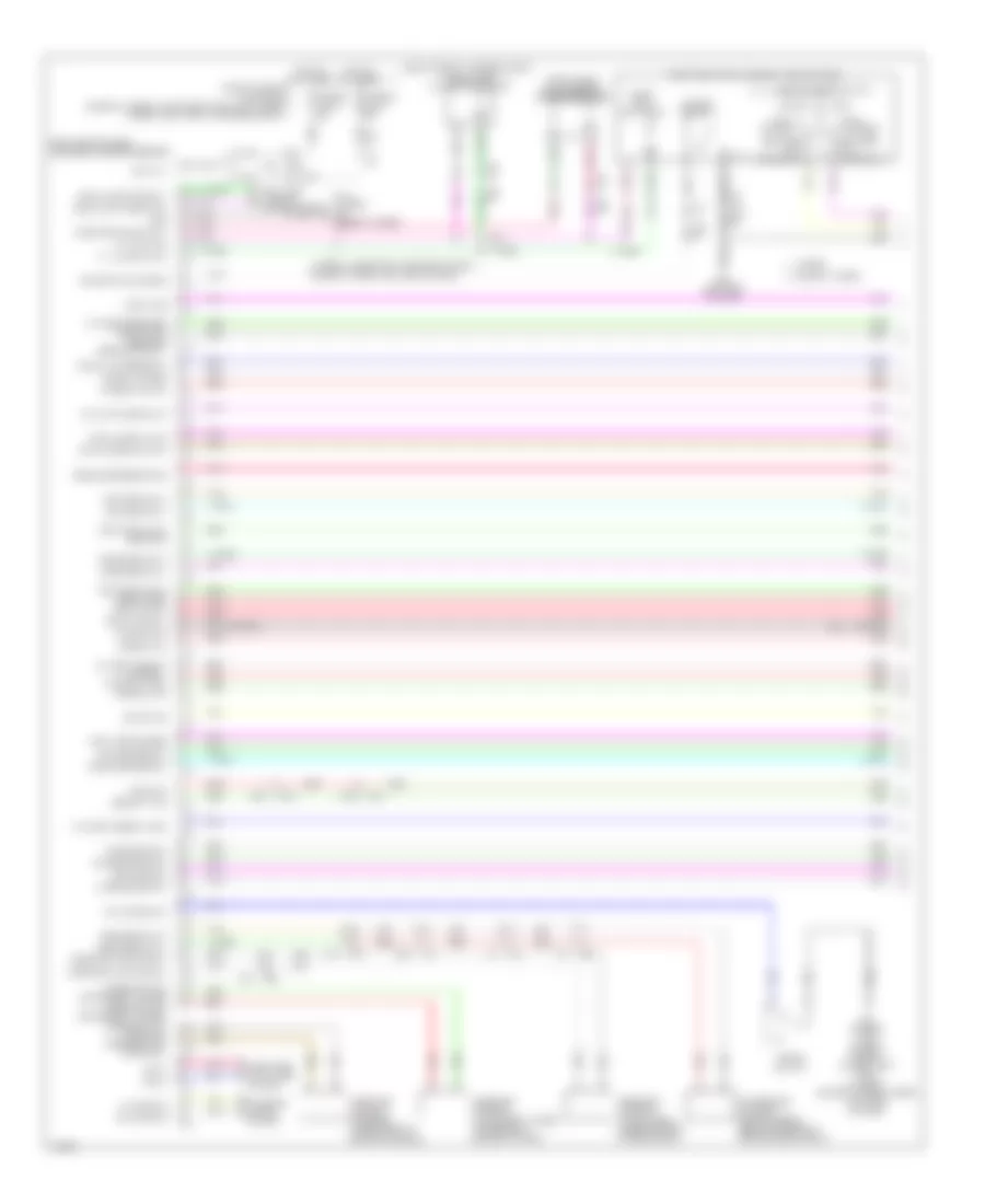
ENGINE PERFORMANCE
3.5L HYBRID
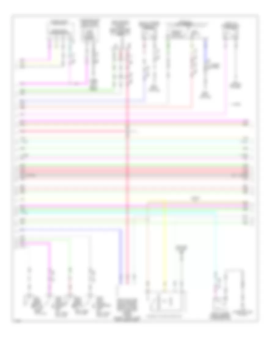
3.5L Hybrid, Engine Controls Wiring Diagram (1 of 5) for Infiniti Q50 Hybrid Sport 2014
List of elements for 3.5L Hybrid, Engine Controls Wiring Diagram (1 of 5) for Infiniti Q50 Hybrid Sport 2014:
- (front of right cylinder bank)
- (front of right cylinder bank) f52
- (right rear of engine) condenser
- (top of left cylinder bank) ignition coil 2 (w/ power transistor)
- (top of left cylinder bank) ignition coil 4 (w/ power transistor)
- (top of left cylinder bank) ignition coil 6 (w/ power transistor)
- (top of right cylinder bank) ignition coil 1 (w/ power transistor)
- (top of right cylinder bank) ignition coil 3 (w/ power transistor)
- (top of right cylinder bank) ignition coil 5 (w/ power transistor)
- A/f sens 1 (b1)
- A/f sens1
- Afh1
- Afh2
- Avcc phase 2
- Can-h
- Can-l
- Close
- Computer data lines system
- E pos sens 1
- E134 (right rear of engine compt)
- Ecm (engine control module) (right front of
- Ecm gnd
- Electric throttle control actuator (bank 2) (on bank 2 throttle body assembly)
- Engine compt)
- Evap
- Evtc valve 1
- Evtc valve 2
- Exhaust valve timing control solenoid valve (bank 1)
- Exhaust valve timing control solenoid valve (bank 2)
- F10
- F11
- Fpr
- Gnd (tps1)
- Gnd pos
- Ign 1
- Ign 2
- Ign 3
- Ign 4
- Ign 5
- Ign 6
- Ignsw
- Intake valve timing control solenoid valve (bank 1)
- Intake valve timing control solenoid valve (bank 2) (front of left cylinder bank)
- Ivtc 1
- Ivtc 2
- Map sens
- Motor (close) 1
- Motor (open) 1
- Motor2 (close)
- Motor2 (open)
- Motrly1
- Nca
- O2hr1
- O2hr2
- Open
- Phase 1
- Plug spark
- Pnk
- Pos
- Pow sup sen2
- Pss phase 1
- Red
- Sens (b2)
- Sens gnd
- Sens pwr tps 1
- Sens pwr tps 2
- Sensor 1
- Sensor 2
- Spark plug
- Ssoff
- Tan
- Throttle control motor
- Throttle position sensor
- Tps1 1
- Tps1 2
- Tps2 1
- Tps2 2
3.5L Hybrid, Engine Controls Wiring Diagram (2 of 5) for Infiniti Q50 Hybrid Sport 2014
List of elements for 3.5L Hybrid, Engine Controls Wiring Diagram (2 of 5) for Infiniti Q50 Hybrid Sport 2014:
- A/t assembly (on transmission)
- B33
- Can h
- Can l
- Close
- Computer data lines system
- Crankshaft position sensor (lower right rear of engine)
- E120
- E123
- E124
- E50
- Ecm relay
- Electric throttle control actuator (bank 1) (on bank 1 throttle body assembly)
- Evap canister purge volume control solenoid valve (right rear of intake manifold)
- F11
- Fuel pump relay
- Fuse 10a
- Fuse 15a
- Hot at all times
- Hot w/ ignition relay energized
- Ipdm e/r (intelligent power distribution module engine room) (right rear of engine compt)
- Joint connector
- Nca
- Open
- Pnk
- Red
- Sensor 1
- Sensor 2
- Tan
- Tcm (transmission control module)
- Throttle control motor
- Throttle control motor relay
- Throttle position sensor
3.5L Hybrid, Engine Controls Wiring Diagram (3 of 5) for Infiniti Q50 Hybrid Sport 2014
List of elements for 3.5L Hybrid, Engine Controls Wiring Diagram (3 of 5) for Infiniti Q50 Hybrid Sport 2014:
- (1, 3 & 5: top inside of right cylinder bank) (2, 4 & 6: top inside of left cylinder bank) fuel injectors
- (on left intake air duct) mass air flow sensor (bank 2)
- (top right side of fuel tank) fuel level sensor unit & fuel pump (main)
- Air fuel ratio (a/f) sensor 1 (bank 1) (right exhaust manifold)
- Air fuel ratio (a/f) sensor 1 (bank 2) (left exhaust manifold)
- B10
- B105 (left "c" pillar)
- B18
- Camshaft position sensor (bank 2) (front of left cylinder bank)
- Can-h
- Can-l
- Combination meter
- Computer data lines system
- Engine coolant temperature sensor (rear of left cylinder bank)
- Engine oil temperature sensor (bottom right front of engine)
- Exhaust valve timing control position sensor (bank 1)
- Exhaust valve timing control position sensor (bank 2)
- F11 e9
- F3 f4
- Fuel pump
- Fuel tank temperature sensor
- Gnd fuel sens
- Ground
- Heated oxygen sensor 2 (bank 2) (left exhaust, middle of catalytic converter)
- Heated oxygen sensor 2 (bank1) (right exhaust, middle of catalytic converter)
- M19
- M57
- M58
- M93 (left end of dash)
- Malfunction ind lamp
- Nca
- Pnk
- Red
- Tan
3.5L Hybrid, Engine Controls Wiring Diagram (4 of 5) for Infiniti Q50 Hybrid Sport 2014
List of elements for 3.5L Hybrid, Engine Controls Wiring Diagram (4 of 5) for Infiniti Q50 Hybrid Sport 2014:
- (right rear of engine compt) icc brake hold relay
- (right rear of engine compt) stop lamp off relay 1
- (top of brake pedal assembly) stop lamp switch
- Atmospheric pressure sensor
- B10
- B18
- B29
- B68
- B83
- Camshaft position sensor (bank 1) (front of right cylinder bank)
- E14
- E47 m39
- E76
- Evap control system pressure sensor (on evap canister)
- F11
- M19
- M22 b62
- Pnk
- Red
- Refrigerant pressure sensor (left side of condenser assembly)
- Tan
3.5L Hybrid, Engine Controls Wiring Diagram (5 of 5) for Infiniti Q50 Hybrid Sport 2014
List of elements for 3.5L Hybrid, Engine Controls Wiring Diagram (5 of 5) for Infiniti Q50 Hybrid Sport 2014:
- (97 to 101 pins not used)
- (on right intake air duct) mass air flow sensor (bank 1)
- 10f
- 11f
- A/f sens 1 (b2)
- B62
- B68
- B83
- Batt cur sen
- Bose amp (w/ bose) (under left center of rear shelf)
- Brake pedal position switch (top of brake pedal assembly)
- Brk sw
- Can-h
- Can-l
- Computer data lines system
- E11
- E134 (right rear of engine compt)
- E25
- E47
- E64
- E65
- Ecm (engine control module) (right front of engine compt)
- Egn spd o/p sig
- Eng oil pr sens
- Engine oil pressure sensor
- Evap canister vent control valve (on evap canister)
- Evap ctrl
- Evap sens
- F10
- F11
- F55
- F67
- Fuel tnk ts
- Fuse 10a
- Fuse block (j/b) (left kick panel)
- Gnd
- Gnd (pha sen)
- Gnd o2 sens 2
- Gnd pos sen2
- Hot at all times
- Hot in on or start
- Iat sens
- Inj 1
- Inj 2
- Inj 3
- Inj 4
- Inj 5
- Inj 6
- Kline
- Knk1
- Knk2
- Knock sensor (bank 1) (under intake manifold, in right cylinder bank)
- Knock sensor (bank 2) (under intake manifold, in left cylinder bank)
- M22
- M39
- M40
- Manifold absolute pressure (map) sensor (left rear of intake manifold)
- Map sen
- Mass af sens1
- Mass af sens2
- O2sr2
- Pnk
- Pwr sply
- Red
- Ref pre sens
- Sens gnd
- Sens gnd2
- Shield
- Snsr pwr sply
- Sps (maf san)
- Stp lp sw
- Tacho
- Tan
- Temp sens
- W/ icc
- W/o icc
3.5L Hybrid, Hybrid System Wiring Diagram (1 of 4) for Infiniti Q50 Hybrid Sport 2014
List of elements for 3.5L Hybrid, Hybrid System Wiring Diagram (1 of 4) for Infiniti Q50 Hybrid Sport 2014:
- Accelerator pedal actuator/ accelerator pedal position sensor (top of accelerator pedal assembly)
- Accelerator pedal position (app) sensor (behind accelerator pedal assembly)
- App sens 1
- App sens 2
- Aps2
- Ascd/icc str sw
- Avcc
- Avcc2
- B105 (left "c" pillar)
- B14
- B18 m19
- B30
- B33
- B35
- Bat
- Batt vol
- Battery cooling fan relay (top of li-ion battery assembly)
- Clutch 1 stroke sens
- Comm-h
- Comm-l
- Computer data lines system
- Cruise control system
- Dc/dc con act sig
- Dc/dc con volt
- E121
- E25
- E50
- Fuse & fusible link block (left front of engine compt)
- Fuse & fusible link block 1 (top of li-ion battery assembly)
- Fuse 10a
- Fuse 20a
- Fusible link x 50a
- Gnd
- Gnd-a
- Gnd-a2
- Hot at all times
- Hot in on or start
- Hpcm (top right side of li-ion battery assembly)
- Hpcm gnd
- Ign
- Ign sig
- Ipdm e/r (intelligent power distribution module engine room) (right rear of engine compt)
- M108 (upper left side of dash)
- M40
- M67 m125
- M93 (left end of dash)
- Nca
- Pnk
- Precharge sig
- Pwr sply from hpcm
- Red
- Self shut off relay
- Self shut off rly
- Sens gnd
- Sens pwr sply
- Sensor gnd
- Shield
- Sply
- Stabilizer sig
- Sys main rly 1
- Sys main rly 2
- T22 (top of li-ion battery assembly)
- T27
- Tan
- W/ intelligent cruise control
- W/o intelligent cruise control
3.5L Hybrid, Hybrid System Wiring Diagram (2 of 4) for Infiniti Q50 Hybrid Sport 2014
List of elements for 3.5L Hybrid, Hybrid System Wiring Diagram (2 of 4) for Infiniti Q50 Hybrid Sport 2014:
- (10 to 16 pins not used)
- (18 to 27 pins not used)
- (36 to 40 pins not used)
- (45 to 49 pins not used)
- (right rear of engine compt) traction motor inverter
- 3-phase
- B104 (left kick panel)
- B17
- Clutch 1
- Computer data lines system
- Detection connection
- E124
- E134 (right rear of engine compt)
- E138 (left rear of engine compt)
- E47
- F11
- F66
- Fuse 10a
- Gnd
- H21
- H22
- Hev sytm can-h
- Hev sytm can-l
- High vol (+)
- High vol (-)
- Hot in on or start
- Ipdm e/r (intelligent power distribution module engine room (right rear of engine compt)
- M18
- M39
- Nca
- Phase-u
- Phase-v
- Phase-w
- Pnk
- Pwr sply (bat)
- Red
- Resolver sig r1 traction mtr
- Resolver sig r2 traction mtr
- Resolver sig s1 traction mtr
- Resolver sig s2 traction mtr
- Resolver sig s3 traction mtr
- Resolver sig s4 traction mtr
- Shield
- Tan
- Traction motor
- Traction motor (inside front of transmission)
3.5L Hybrid, Hybrid System Wiring Diagram (3 of 4) for Infiniti Q50 Hybrid Sport 2014
List of elements for 3.5L Hybrid, Hybrid System Wiring Diagram (3 of 4) for Infiniti Q50 Hybrid Sport 2014:
- (or tan)
- (right rear of engine compt) icc brake hold relay
- (top of li-ion battery assembly) stop lamp off relay 2
- 11f
- 26c
- A/t assembly
- Anti-lock brakes system
- B10
- B104 (left kick panel)
- B105 (left "c" pillar)
- B15
- B16
- B17
- B29
- B30 t3
- B39
- Body control module (right end of dash)
- Brake pedal position switch (top of brake pedal assembly)
- Brk pedal pos sw
- Can-h
- Can-l
- Computer data lines system
- E134 (right rear of engine compt)
- E25
- E47
- E64
- E65
- Electric water pump (right side of radiator)
- Eltc water pump
- F11
- Fuse 10a
- Fuse block (j/b) (left kick panel)
- Hev sys can-h
- Hev sys can-l
- Hot at all times
- Hot in on or start
- Hpcm (top right side of li-ion battery assembly)
- Hpcm gnd
- Interlock sw sig
- Joint connector
- M13
- M133
- M14
- M18
- M34
- M40
- P/n pos
- P/n sig
- Pnk
- Ready sig
- Red
- Service plug
- Shield
- Start rly cont
- Stop lamp off relay 1 (right rear of engine compt)
- Stop lamp sw
- Stop lamp switch (top of brake pedal assembly)
- Tan
- Tcm (transmission control module)
- W/ intelligent cruise control
- W/o intelligent cruise control
3.5L Hybrid, Hybrid System Wiring Diagram (4 of 4) for Infiniti Q50 Hybrid Sport 2014
List of elements for 3.5L Hybrid, Hybrid System Wiring Diagram (4 of 4) for Infiniti Q50 Hybrid Sport 2014:
- (left side of li-ion battery compt) sub electric oil pump inverter
- (on transmission assembly) sub electric oil pump
- (right side of luggage compt) battery cooling fan
- (top of li-ion battery assembly) sub electric oil pump relay
- Active sig
- Air con seat rly
- B10
- B29
- B30
- Battery terminal w/ fusible link
- C21
- Can-h
- Can-l
- Colling mode req sig
- Computer data lines system
- Dc/dc converter
- E124
- Electric compressor (left front of engine compt)
- Fuse 10a
- Fusible link a 250a
- Fusible link f 50a
- Gnd
- H13 (near li-ion battery assembly)
- H17
- Hi volt (+)
- Hi volt (-)
- Hot at all times
- Hot in on or start
- Ipdm e/r (intelligent power distribution module engine room) (right rear of engine compt)
- Junction box
- Li-ion battery (left side of li-ion battery assembly)
- Li-ion battery controller
- Nca
- Oil pmp rly
- Pnk
- Pwr sply
- Red
- Seats system
- Shield
- Sply
- T101
- T102
- T22 (top of li-ion battery assembly)
- T28
- T304
- T305
- T43 (left center rear of luggage compt)
- T46
- Tan
- U-phase
- V-phase
- Volt stability sig
- W-phase
3.7L
3.7L, Engine Performance Wiring Diagram (1 of 7) for Infiniti Q50 Hybrid Sport 2014
List of elements for 3.7L, Engine Performance Wiring Diagram (1 of 7) for Infiniti Q50 Hybrid Sport 2014:
- (1, 3 & 5: top of right cylinder bank) (2, 4 & 6: top of left cylinder bank)
- (lower right center of dash) m111
- A/f sens 1 bnk 1
- A/f sens1 htr bnk 1
- A/f sens1 htr bnk 2
- Abort sig
- Bnk 1 close
- Bnk 1 open
- Bnk 2 close
- Bnk 2 open
- Close
- Computer data lines system
- Condenser (right rear of engine)
- Crankshaft position sensor (pos) (lower right rear of engine)
- E10
- Ecm (engine control module) (under right end of dash)
- Electric throttle control actuator (bank 2) (on bank 2 throttle body assembly)
- Eng comm line
- Evap
- F12
- F20
- F52 (front of right cylinder bank)
- F57
- F58
- F58 f57
- Fpcm
- Fuel pmp rly
- Gnd
- Ign 1
- Ign 2
- Ign 3
- Ign 4
- Ign 5
- Ign 6
- Ignition coil 1 (w/ power transistor)
- Ignition coil 2 (w/ power transistor)
- Ignition coil 3 (w/ power transistor)
- Ignition coil 4 (w/ power transistor)
- Ignition coil 5 (w/ power transistor)
- Ignition coil 6 (w/ power transistor)
- Ignsw
- Intake valve timing control solenoid valve (bank 1) (front of right cylinder bank)
- Intake valve timing control solenoid valve (bank 2) (front of left cylinder bank)
- M111 (lower right center of dash)
- M36
- Mtr rly
- Nca
- Open
- Pnk
- Pos sens
- Pwr sply bnk 1
- Pwr sply bnk 2
- Red
- Sens 1 bnk 1
- Sens 1 bnk 2
- Sens 2 bnk 1
- Sens 2 bnk 2
- Sens 2 htr bnk 1
- Sens 2 htr bnk 2
- Sens bnk 1
- Sens bnk 2
- Sens gnd
- Sens pwr sply
- Sensor 1
- Sensor 2
- Spark plug
- Ssoff
- Tan
- Throttle control motor
- Throttle position sensor
- Vlv bnk 1
- Vlv bnk 2
3.7L, Engine Performance Wiring Diagram (2 of 7) for Infiniti Q50 Hybrid Sport 2014
List of elements for 3.7L, Engine Performance Wiring Diagram (2 of 7) for Infiniti Q50 Hybrid Sport 2014:
- -h can
- -l can
- A/t assembly a/t assembly (on transmission)
- B33
- Close
- Computer data lines system
- Cooling fans system
- Cpu
- E10
- E120
- E121
- E123
- E124
- E126
- E134 (right rear of engine compt)
- E25
- E50
- Ecm relay
- Electric throttle control actuator (bank 1) (on bank 1 throttle body assembly)
- Evap canister purge volume control solenoid valve (right rear of intake manifold)
- F12
- F20
- Fuel pump relay
- Fuse 10a
- Fuse 15a
- Hot at all times
- Ignition relay
- Ipdm e/r (intelligent power distribution module engine room) (right rear of engine compt)
- J/c
- M36
- M39 e47
- M40
- Nca
- Open
- Pnk
- Red
- Rly str
- Sensor 1
- Sensor 2
- Starting/charging system
- Tan
- Tcm (transmission control module) control module)
- Throttle control motor
- Throttle control motor relay
- Throttle position sensor
3.7L, Engine Performance Wiring Diagram (3 of 7) for Infiniti Q50 Hybrid Sport 2014
List of elements for 3.7L, Engine Performance Wiring Diagram (3 of 7) for Infiniti Q50 Hybrid Sport 2014:
- (1, 3 & 5: top inside of right cylinder bank) (2, 4 & 6: top inside of left cylinder bank)
- Air fuel ratio (a/f) sensor 1 (bank 1) (right exhaust, upstream of catalytic converter)
- Air fuel ratio (a/f) sensor 1 (bank 2) (left exhaust, upstream of catalytic converter)
- Engine coolant temperature sensor (rear of left cylinder bank)
- Engine oil temperature sensor (awd: on oil filter housing) (2wd: bottom right front of engine)
- F39
- F70
- Fuel injector 1
- Fuel injector 2
- Fuel injector 3
- Fuel injector 4
- Fuel injector 5
- Fuel injector 6
- Heated oxygen sensor 2 (bank 1) (right exhaust, middle of catalytic converter)
- Heated oxygen sensor 2 (bank 2) (left exhaust, middle of catalytic converter)
- M111 (lower right center of dash)
- Nca
- Pnk
- Red
- Tan
3.7L, Engine Performance Wiring Diagram (4 of 7) for Infiniti Q50 Hybrid Sport 2014
List of elements for 3.7L, Engine Performance Wiring Diagram (4 of 7) for Infiniti Q50 Hybrid Sport 2014:
- (left rear of luggage compt) fuel pump control module
- (on left intake air duct) mass airflow sensor (bank2)
- (top right side of fuel tank) fuel level sensor & fuel pump
- B105 (left "c" pillar)
- B18 m19
- B62
- B68
- B83
- Camshaft position sensor (phase) (bank 2) (left of right cylinder bank)
- Combination meter
- Computer data lines system
- Engine oil pressure warning ind
- Evap canister vent control valve (on evap canister)
- F20
- F20 m36
- F5 f6
- Fuel filler cap warning ind
- Fuel pump motor
- Fuel tank level
- Fuel tank temperature sensor
- Instrument cluster system
- M22
- M36
- M58
- M93 (left end of dash)
- Malfunction ind
- Pnk
- Power steering pressure sensor (if equipped) (right front of engine)
- Red
- Sensor
- Tan
3.7L, Engine Performance Wiring Diagram (5 of 7) for Infiniti Q50 Hybrid Sport 2014
List of elements for 3.7L, Engine Performance Wiring Diagram (5 of 7) for Infiniti Q50 Hybrid Sport 2014:
- (right rear of engine compt) e134
- (right rear of engine compt) vvel control module
- Abort sig
- Computer data lines system
- E10
- E134 (right rear of engine compt)
- Eng comm line
- F12
- Gnd
- Hi lift bnk 2
- Lo lift bnk 1
- Lo lift bnk 2
- Mtr rly
- Nca
- Pnk
- Red
- Sens 1 bnk 1
- Sens 1 bnk 2
- Sens 2 bnk 1
- Sens 2 bnk 2
- Sens gnd
- Sensor 1
- Sensor 2
- Shield
- Sng comm line
- Tan
- Vvel actuator motor (bank 1) (top center rear of engine)
- Vvel actuator motor (bank 2) (top rear of left cylinder bank)
- Vvel bnk 1
- Vvel bnk 2
- Vvel control shaft position sensor (bank 1) (rear of right cylinder bank)
- Vvel control shaft position sensor (bank 2) (rear of left cylinder bank)
- Vvel ctrl
3.7L, Engine Performance Wiring Diagram (6 of 7) for Infiniti Q50 Hybrid Sport 2014
List of elements for 3.7L, Engine Performance Wiring Diagram (6 of 7) for Infiniti Q50 Hybrid Sport 2014:
- (in relay box) vvel actuator motor relay
- (or red)
- 11f
- 26c
- Accelerator pedal actuator/accelerator pedal position sensor (top of accelerator pedal assembly)
- Accelerator pedal position sensor (behind accelerator pedal assembly)
- Battery temperature sensor
- Brake pedal position switch (top of brake pedal assembly)
- Camshaft position sensor (phase) (bank 1) (front of right cylinder bank)
- E10
- E47
- E64
- E65
- F12
- F20
- Fuse & fusible link block 1 (top of liion battery assembly)
- Fuse 10a
- Fuse block (j/b) (left kick panel)
- Fusible link p 50a
- Hot at all times
- Hot w/ ignition relay energized
- M133
- M36
- M39
- M67 m125
- M93 (left end of dash)
- Nca
- Pnk
- Red
- Sensor 1
- Sensor 2
- Tan
- W/ icc
- W/o icc
3.7L, Engine Performance Wiring Diagram (7 of 7) for Infiniti Q50 Hybrid Sport 2014
List of elements for 3.7L, Engine Performance Wiring Diagram (7 of 7) for Infiniti Q50 Hybrid Sport 2014:
- (right rear of engine compt) icc brake hold relay
- (top of brake pedal assembly) stop lamp switch
- (under intake manifold, in left cylinder bank) knock sensor (bank 2)
- (under intake manifold, in right cylinder bank) knock sensor (bank 1)
- A/f sens 1 bnk 1
- A/f sens 1 bnk 2
- Air temp sens
- Aps1
- Aps2
- B68 b83
- Bat temp sens
- Brk pdl postn sw
- Can comm line
- Computer data lines system
- Coolent tempsens
- Cruise control system
- Current sens
- Data link conn
- E10
- E14
- E25
- E76
- Ecm (engine control module) (under right end of dash)
- Eng oil temp sens
- Eng spd sig out
- Evap control system pressure sensor (on evap canister)
- Evap ctrl sens
- Evap ctrl vlv
- F12
- F20 m36
- F55
- F67
- F67 f55
- Ful tnk temp sens
- Gnd
- Gnda cursen
- Gnda phase1/ps
- Gnda-pdpres/ftprs
- Htd sens 2 bnk 1
- Htd sens 2 bnk 2
- Inj 1
- Inj 2
- Inj 3
- Inj 4
- Inj 5
- Inj 6
- Intake air temperature sensor
- Knock sens bnk 1
- Knock sens bnk 2
- M111 (lower right center of dash)
- M22 b62
- M37
- M40
- Mafs bnk 1
- Mafs bnk 2
- Mass airflow sensor w/intake air temperature sensor (bank 1) (on right intake air duct)
- Pnk
- Power steering control unit (if equipped) (right end of dash)
- Pwr sply
- Pwr sply aps1
- Pwr sply aps2
- Pwr strg sens
- Red
- Ref press sens
- Refrigerant pressure sensor (left side of condenser assembly)
- Sens gnd
- Sens gnd aps1
- Sens gnd aps2
- Sens pwr sply
- Shield
- Shield shield
- Sig spd
- Stop lp sw
- Strg sw
- Tan
- Trans range sw
EXTERIOR LIGHTS
Backup Lamps Wiring Diagram for Infiniti Q50 Hybrid Sport 2014
List of elements for Backup Lamps Wiring Diagram for Infiniti Q50 Hybrid Sport 2014:
- 32c
- A/t assembly (on transmission)
- Around view monitor control unit (under right end of rear shelf)
- B107 (right "b" pillar)
- B62
- B66
- Backup
- Backup lamp relay
- Display control unit
- E10
- Except hybrid
- F11
- F12
- Fuse 5a
- Fuse block (j/b) (left kick panel)
- Hot w/ ignition relay energized
- Hybrid
- Joint connector
- Lamp rly
- Left rear combination lamp (trunk lid side)
- M133
- M39
- Nca
- Red
- Reverse sig b50
- Reverse sig m100
- Right rear combination lamp (trunk lid side)
- Sw1
- Sw2
- Sw3
- Sw4
- T48
- Tan
- Transmission control module (tcm)
- Transmission range switch
Exterior Lamps Wiring Diagram (1 of 2) for Infiniti Q50 Hybrid Sport 2014
List of elements for Exterior Lamps Wiring Diagram (1 of 2) for Infiniti Q50 Hybrid Sport 2014:
- (except hybrid: left "c" pillar) (hybrid: left center rear of luggage compt) (except hybrid) b105 (hybrid) t43
- (top of brake pedal assembly) stop lamp switch
- (upper left side of dash) m108
- 10h
- 14c
- 27c
- 36c
- B18
- B35
- B39
- B41
- Bat (f/l)
- Bat (fuse)
- Bcm (body control module) (right end of dash)
- Can-h
- Can-l
- Cbim sw i/p 1
- Cbim sw i/p 2
- Cbim sw i/p 3
- Cbim sw i/p 4
- Cbim sw i/p 5
- Cbim sw o/p 1
- Cbim sw o/p 2
- Cbim sw o/p 3
- Cbim sw o/p 4
- Cbim sw o/p 5
- Computer data lines system
- Cruise control system
- D18
- D18 m34
- Dri door sw
- Driver side door mirror (turn signal)
- E25
- E64
- E65
- Fuse & fusible link block (hybrid: left front of engine compt) (except hybrid: on battery positive (+) post)
- Fuse & fusible link block 1 (top of li-ion battery assembly)
- Fuse 10a
- Fuse 5a
- Fuse block (j/b) (left kick panel)
- Fuse sw
- Fusible link m 40a
- Fusible link t 40a
- Gnd
- Haz sw
- Hazard
- Hot at all times
- Hybrid w/ icc
- Hybrid w/o icc & except hybrid
- Integral switch (hazard switch)
- Interior lights system
- Left front turn signal lamp
- Left rear combination lamp (body side)
- Left sig o/p
- Lf sig o/p
- Lr door sw
- M108 (except hybrid) m111 (hybrid) (except hybrid: upper left side of dash) (hybrid: lower right center of dash)
- M108 (upper left side of dash)
- M13
- M133
- M14
- M15
- M16
- M17
- M19
- M33
- M34
- M40
- M93 (left end of dash)
- Pass door sw
- Passenger side door mirror (turn signal)
- Pnk
- Red
- Rf sig o/p
- Rh sig o/p
- Right front turn signal lamp
- Rr door sw
- Sig
- Stop
- Stop lamp off relay 1 (right rear of engine compt)
- Stop lamp sw
- T25
- T27
- Tail
- Tan
- Turn signal
Exterior Lamps Wiring Diagram (2 of 2) for Infiniti Q50 Hybrid Sport 2014
List of elements for Exterior Lamps Wiring Diagram (2 of 2) for Infiniti Q50 Hybrid Sport 2014:
- (except hybrid: left "c" pillar) (hybrid: left center rear of luggage compt) (except hybrid) b105 (hybrid) t43
- (left "c" pillar) b105
- (left rear of engine compt) abs actuator & electric unit
- (right end of dash) (w/ icc) resistor
- (right rear of engine compt) e134
- B107 (right "b" pillar)
- B18
- B35
- B37
- B37 b72
- B66
- B72
- B75
- Backup
- Backup lamps circuit
- Battery terminal w/ fusible link (on battery positive (+) post)
- Can-h
- Can-l
- Combination meter
- Combination switch
- Computer data lines system
- Condenser (hybrid) (top of li-ion battery assembly) t33
- Cpu
- E118
- E120
- E121
- E126
- E128
- E137 (left rear of engine compt)
- E47
- Except hybrid
- Fuse & fusible link block (hybrid: left front of engine compt) (except hybrid: on battery positive (+) post)
- Fuse 10a
- Fusible link f 60a
- Fusible link p 60a
- High mounted stop lamp
- Hot at all times
- Hybrid
- Input 1
- Input 2
- Input 3
- Input 4
- Input 5
- Interior lights system
- Ipdm e/r (intelligent power distribution module engine room) (right rear of engine compt)
- Left front combination lamp
- Left license plate lamp
- Left rear combination lamp (trunk lid side)
- M19
- M39
- M40 e25
- M58
- M93 (left end of dash)
- Out put 1
- Out put 2
- Out put 3
- Out put 4
- Out put 5
- Pnk
- Red
- Right front combination lamp
- Right license plate lamp
- Right rear combination lamp (body side)
- Right rear combination lamp (trunk lid side)
- Stop
- T21
- T27
- T32
- T48
- T48 b66
- Tail
- Tail lamp relay
- Tan
- Trunk lid opener request switch assembly
- Turn signal
GROUND DISTRIBUTION
Ground Distribution Wiring Diagram, Except Hybrid (1 of 2) for Infiniti Q50 Hybrid Sport 2014
List of elements for Ground Distribution Wiring Diagram, Except Hybrid (1 of 2) for Infiniti Q50 Hybrid Sport 2014:
- Abs actuator & electric unit (control unit)
- Brake fluid level switch, left front fog lamp, steering angle main control module (w/ direct adaptive steering), steering angle sub control module (w/ direct adaptive steering), washer level switch, cooling fan control module, shift lock relay, right front combination lamp, hood switch, horn low, horn high, left front turn signal lamp & chassis control module
- Combination switch, afs control module, blower motor, can gateway, data link connector, dongle unit (canada), driver mode select switch, push button ignition switch, automatic drive positioner control unit, glove box lamp, heated seat relay, heated steering wheel, power steering control unit (if equipped), driver assistance buzzer control module, combination meter, paddle shifter (down), paddle shifter (up), steering angle sensor, triple switch, tcu, trunk lid opener cancel switch, resistor, tilt & telescopic switch (w/ memory), accelerator pedal actuator/ accelerator pedal position sensor shield (w/ icc), accelerator pedal position sensor shield (w/o icc), force motor angle sensor shield (w/ direct adaptive steering), fuse block (j/b), left air mix door motor, mode door motor, intake door motor, right air mix door motor, front door lock assembly (driver side), driver side door mirror, front outside handle assembly (driver side), power window main switch, seat memory switch, front one touch unlock sensor assembly (driver side), map lamp, rain sensor, auto anti-dazzling inside mirror, sunroof switch, lane camera unit, personal lamp, telematics switch, passenger side vanity mirror lamp & driver side vanity mirror lamp
- E134 (right rear of engine compt)
- E135 (left rear of engine compt)
- E136 (right rear of engine compt)
- E137 (left rear of engine compt)
- E140 (left rear of engine compt)
- Electric throttle control actuator (bank 2) shield, electric throttle control actuator (bank 1) shield, air fuel ratio (a/f) sensor 1 (bank 1) shield, air fuel ratio (a/f) sensor 1 (bank 2) shield, manifold absolute pressure (map) sensor shield, bcm (body control module), ecm (engine control module) & steering force control module (w/ direct adaptive steering)
- Integral switch, air bag diagnosis sensor unit, a/t shift selector, av control unit, bcm (body control module), external data input box, external data input box shield, awd control unit, ionizer (w/ accs), navi control unit (w/ navigation), power socket 1, power socket 2, sonar control unit, triple switch, a/c auto amp, display control unit, passenger side door mirror, passenger side front power window switch, front one touch unlock sensor assembly (passenger side), front outside handle assembly (passenger side) & sunroof motor assembly
- Ipdm e/r (intelligent power distribution module engine room), icc sensor, vehicle security horn, left front combination lamp, vvel control module, vvel control shaft position sensor (bank 1) shield, vvel control shaft position sensor (bank 2) shield, vvel actuator motor (bank 1) shield, vvel actuator motor (bank 2) shield, main motor angle sensor shield (w/ direct adaptive steering), steering torque sensor (w/ direct adaptive steering), sub motor angle sensor shield (w/ direct adaptive steering), front wiper motor, right front turn signal lamp & right front fog lamp
- M108 (upper left side of dash)
- M111 (lower right center of dash)
- M93 (left end of dash)
- Steering angle main control module (w/ direct adaptive steering)
- Steering angle sub control module (w/ direct adaptive steering)
Ground Distribution Wiring Diagram, Except Hybrid (2 of 2) for Infiniti Q50 Hybrid Sport 2014
List of elements for Ground Distribution Wiring Diagram, Except Hybrid (2 of 2) for Infiniti Q50 Hybrid Sport 2014:
- (or nca)
- Adas control unit shield (w/ icc), adas control unit, driver side seat belt buckle switch, fuel pump control module, fuel level sensor unit & fuel pump (main) shield, left rear combination lamp, right rear combination lamp, right side radar shield (w/ icc), left side radar shield (w/ icc), high mounted stop lamp, left side radar, right side radar, blind spot warning/ left blind spot intervention indicator & blind spot warning/ right blind spot intervention indicator
- Av control unit shield (w/o base), around view monitor control unit shield, around view monitor control unit, bose amp, passenger side seat belt buckle switch, right rear power window switch, trunk lid opener request switch assembly, left rear combination lamp, right rear combination lamp & trunk lid lock assembly
- Av control unit shield, occupant detection system control unit, passenger side front power seat (power seat switch) (w/o memory), around view monitor control unit shield, ads control unit shield (w/ icc), passenger side pre-crash seat belt control unit & power seat switch
- B104 (left kick panel)
- B105 (left "c" pillar)
- B106 (right kick panel)
- B107 (right "b" pillar)
- B473
- Chassis control module shield, driver side pre-crash seat belt control unit, driver seat control unit, around view monitor control unit shield (w/o icc), ads control unit shield (w/ icc), driver side front power seat (power seat switch), sliding motor, reclining motor, rear lifting motor, front lifting motor, lumbar support switch, back side support assembly, side support switch & left rear power window switch
- Compressor & a/t assembly
- F51 (front of right cylinder bank)
- F52 (front of right cylinder bank)
- Ignition coil 1 (w/ power transistor), ignition coil 2 (w/ power transistor), ignition coil 3 (w/ power transistor), ignition coil 4 (w/ power transistor), ignition coil 5 (w/ power transistor), ignition coil 6 (w/ power transistor) & condenser
- Nca
- Rear window defogger
Ground Distribution Wiring Diagram, Hybrid (1 of 2) for Infiniti Q50 Hybrid Sport 2014
List of elements for Ground Distribution Wiring Diagram, Hybrid (1 of 2) for Infiniti Q50 Hybrid Sport 2014:
- Abs actuator & electric unit (control unit)
- Afs control module, blower motor, can gateway, data link connector, combination switch, dongle unit (canada), driver mode select switch, push button ignition switch, automatic drive positioner control unit, glove box lamp, ionizer (w/ accs), heated steering wheel, force motor angle sensor shield, driver assistance buzzer control module, combination meter, paddle shifter (down), paddle shifter (up), steering angle sensor, triple switch, tcu, trunk lid opener cancel switch, resistor, tilt & telescopic switch (w/ memory), accelerator pedal actuator/ accelerator pedal position sensor shield (w/ icc), accelerator pedal position sensor shield (w/o icc), accelerator pedal actuator/ fuse block (j/b), left air mix door motor, mode door motor, intake door motor, right air mix door motor, front door lock assembly (driver side), driver side door mirror, front outside handle assembly (driver side), power window main switch, seat memory switch, front one touch unlock sensor assembly (driver side), map lamp, rain sensor, auto anti-dazzling inside mirror, sunroof switch, lane camera unit, personal lamp, telematics switch, passenger side vanity mirror lamp & driver side vanity mirror lamp
- Bcm (body control unit), a/c auto amp & steering force control module
- Bose amp, integral switch, air bag diagnosis sensor unit, a/t shift selector, av control unit, bcm (body control module), external data input box, external data input box shield, awd control unit, navi control unit (w/ navigation), power socket 1, power socket 2, sonar control unit, a/c auto amp, display control unit, passenger side door mirror, passenger side front power window switch, front one touch unlock sensor assembly (passenger side), front outside handle assembly (passenger side) & sunroof motor assembly
- Brake pedal stroke sensor shield, brake fluid level switch, front wiper motor, heater pump, cooling fan control module, shift lock relay, electrically driven intelligent brake unit, washer level switch, horn high & electric compressor, main motor angle sensor shield, steering torque sensor shield & sub motor angle sensor shield
- E134 (right rear of engine compt)
- E135 (left rear of engine compt)
- E136 (right rear of engine compt)
- E137 (left rear of engine compt)
- E138 (left rear of engine compt)
- E140 (left rear of engine compt)
- Electrically driven intelligent brake unit
- M108 (upper left side of dash)
- M111 (lower right center of dash)
- M93 (left end of dash)
- Steering angle main control module
- Steering angle sub control module
- Traction motor inverter, right front fog lamp, right front turn signal lamp, electric water pump, left front combination lamp, vehicle security horn, icc sensor, electric throttle control actuator (bank 2) shield, electric throttle control actuator (bank 1) shield, air fuel ratio (a/f) sensor 1 (bank 1) shield, air fuel ratio (a/f) sensor 1 (bank 2) shield, ecm (engine control module) & ipdm e/r (intelligent power distribution module engine room)
Ground Distribution Wiring Diagram, Hybrid (2 of 2) for Infiniti Q50 Hybrid Sport 2014
List of elements for Ground Distribution Wiring Diagram, Hybrid (2 of 2) for Infiniti Q50 Hybrid Sport 2014:
- (or nca)
- A/t assembly
- Adas control unit, hpcm, driver side seat belt buckle switch & fuel level sensor unit & fuel pump (main)
- B104 (left kick panel)
- B105 (left "c" pillar)
- B106 (right kick panel)
- B107 (right "b" pillar)
- B473
- Chassis control module shield (w/ icc), approaching vehicle sound for pedestrains (vsp) control unit shield, hpcm shield, driver side pre-crash seat belt control unit, approaching vehicle sound for pedestrains (vsp) control unit, driver seat control unit, driver side front seat (power seat switch), back side support assembly, side support switch) sliding motor, reclining motor, rear lifting motor & front lifting motor, lumbar support switch & left rear power window switch
- F51 (front of right cylinder bank)
- F52 (front of right cylinder bank)
- H13 (near li-ion battery assembly)
- High-mounted stop lamp
- Ignition coil 1 (w/ power transistor), ignition coil 2 (w/ power transistor), ignition coil 3 (w/ power transistor), ignition coil 4 (w/ power transistor), ignition coil 5 (w/ power transistor), ignition coil 6 (w/ power transistor) & condenser
- Nca
- Occupant detection system control unit, passenger side pre-crash control unit, passenger side front power seat (power seat switch), passenger side seat belt buckle switch, bose amp shield & around view monitor control unit shield
- Rear window defogger
- Sub electric oil pump inverter, battery cooling fan, left rear combination lamp, adas control unit, right rear combination lamp, left side radar, right side radar, right blind spot warning/ blind spot intervention indicator & left blind spot warning/ blind spot intervention indicator
- Sub electric oil pump shield
- T22 (top of li-ion battery assembly)
- T43 (left center rear of luggage compt)
- T6 (top of li-ion battery assembly)
- Trunk lid lock assembly, right rear combination lamp, left rear combination lamp, trunk lid opener request switch assembly, right sliding door power window switch, passenger side seat belt buckle switch, bose amp, around view monitor control unit & right rear power window switch
HEADLIGHTS
Adaptive Front Lighting Wiring Diagram for Infiniti Q50 Hybrid Sport 2014
List of elements for Adaptive Front Lighting Wiring Diagram for Infiniti Q50 Hybrid Sport 2014:
- (left end of dash) m93
- 11f
- 30c
- Afs control unit (right end of dash)
- Aiming gnd
- Amplifier
- B18
- Can-h
- Can-l
- Combination meter
- Computer data lines system
- E14
- E25
- E65
- E76
- E76 e14
- Except hybrid
- Fuse 10a
- Fuse 5a
- Fuse block (j/b) (left kick panel)
- Gnd
- Height sensor (left rear wheelwell)
- Hot w/ ignition relay energized
- Ht sens gnd
- Ht sens pwr sply drv sig
- Hybrid
- Left headlamp swivel actuator (in left headlamp assembly)
- Left headlight aiming motor (rear of left headlamp assembly)
- Lin sig
- M133
- M19
- M40
- M58
- Pnk
- Pwr sply
- Red
- Right headlamp swivel actuator (in right headlamp assembly)
- Right headlight aiming motor (rear of right headlamp assembly)
- Sens sig
- Swivel gnd
- Tan
Headlamps Wiring Diagram (1 of 2) for Infiniti Q50 Hybrid Sport 2014
List of elements for Headlamps Wiring Diagram (1 of 2) for Infiniti Q50 Hybrid Sport 2014:
- (left end of dash)
- B18
- B41
- Bat (f/l)
- Bat pwr sply
- Body control module (bcm) (right end of dash)
- Can-h
- Can-l
- Comb sw in 1
- Comb sw in 2
- Comb sw in 3
- Comb sw in 4
- Comb sw in 5
- Comb sw out 1
- Comb sw out 2
- Comb sw out 3
- Comb sw out 4
- Comb sw out 5
- Combi sw in 1
- Combi sw in 2
- Combi sw in 3
- Combi sw in 4
- Combi sw in 5
- Combi sw out 1
- Combi sw out 2
- Combi sw out 3
- Combi sw out 4
- Combi sw out 5
- Combination meter
- Combination switch
- Computer data lines system
- Daytime running light relay (in fuse & fusible link block)
- Dr door sw
- E25
- Except hybrid
- Fuse & fusible link block (left front of engine compt)
- Fuse & fusible link block (on battery positive (+) post)
- Fuse & fusible link block 1 (top of li-ion battery assembly)
- Fuse 6 10a
- Fuse 72 10a
- Fuse 73 10a
- Fuse block (j/b) (left kick panel)
- Fusible link m 40a
- Fusible link t 40a
- Gnd
- Hot at all times
- Hybrid
- Interior lights system
- Lh hdlp warning sig
- M108 (except hybrid) m111 (hybrid) (except hybrid: upper left side of dash) (hybrid: lower right center of dash)
- M13
- M133 28c
- M14
- M15
- M17
- M19
- M40
- M57
- M58
- M93
- Optical sens
- Optical sensor (top right side of dash)
- Output
- Parking brake switch (base of parking brake lever assembly)
- Pass door sw
- Pnk
- Pwr
- Rh hdlp warning sig
- Rl door sw
- Rr door sw
- Sens gnd
- Sens pwr sply
- Sw sig
- T25
- Tan
Headlamps Wiring Diagram (2 of 2) for Infiniti Q50 Hybrid Sport 2014
List of elements for Headlamps Wiring Diagram (2 of 2) for Infiniti Q50 Hybrid Sport 2014:
- Battery terminal w/ fusible link (on battery positive (+) post)
- Computer data lines system
- E118
- E120
- E121
- E125
- E126
- E128
- E134 (left rear of engine compt)
- E134 (right rear of engine compt)
- E137 (left rear of engine compt)
- E137 (right rear of engine compt)
- Except hybrid
- Front fog lamp relay
- Fuse & fusible link block (left front of engine compt)
- Fuse 10a
- Fuse 15a
- Fusible link f 60a
- Fusible link p 60a
- Headlamp high relay
- Headlamp low relay
- Hot at all times
- Hybrid
- Ipdm e/r (intelligent power distribution module engine room) (right rear of engine compt)
- Left front combination lamp
- Left front fog lamp
- Pnk
- Red
- Red (or pnk)
- Right front combination lamp
- Right front fog lamp
HORN
Horn Wiring Diagram for Infiniti Q50 Hybrid Sport 2014
List of elements for Horn Wiring Diagram for Infiniti Q50 Hybrid Sport 2014:
- Combination switch (spiral cable) (in steering column)
- E121
- E137 (left rear of engine compt)
- E138 (left rear of engine compt)
- E14
- E25
- E47
- E76
- E78
- E79
- E85
- E86
- Except hybrid
- Fuse & fusible link block (except hybrid: on battery positive (+) post) (hybrid: left front of engine compt)
- Fuse 66 15a
- Horn (high) (behind right side of front grille)
- Horn (low) (behind left side of front grille)
- Horn relay (in fuse & fusible link block)
- Horn switch
- Hot at all times
- Hybrid
- Ipdm e/m (intelligent power distribution module engine room) (right rear of engine compt)
- M301
- M303
- M39
- M40
- M86
- Nca
INSTRUMENT CLUSTER
Instrument Cluster Wiring Diagram (1 of 2) for Infiniti Q50 Hybrid Sport 2014
List of elements for Instrument Cluster Wiring Diagram (1 of 2) for Infiniti Q50 Hybrid Sport 2014:
- (bottom front of engine) (except hybrid) oil pressure switch
- (or red)
- 28c
- 32c
- 39c
- Air bag sig
- Alternator sig
- B18
- Battery power voltage
- Brk fluid sw sig
- Can-h
- Can-l
- Combination meter
- Comm sig (h)
- Comm sig (l)
- Computer data lines system
- Cpu
- Drv seat belt bck sw
- E10 f12
- E121
- E124
- E25
- E25 m40
- Electronic power steering system
- Except hybrid
- Fuel level sen gnd
- Fuel level sensor sig
- Fuel level sensor unit & fuel pump (main) (top right side of fuel tank)
- Fuel level sensor unit (sub) (top left side of fuel tank)
- Fuse 10a
- Fuse 10a 5a
- Fuse 5a
- Fuse block (j/b) (left kick panel)
- Gnd
- Ground
- Headlights system
- Hot at all times
- Hybrid
- Ign sig
- Ill ctrl sig
- Ill ctrl sw (+)
- Ill ctrl sw (-)
- Illumination control switch
- Illumination control switch (illumination)
- Interior lights system
- Ipdm e/r (intelligent power distribution module engine room) (right rear of engine compt)
- Led hdlp (lh) warn sig
- Led hdlp (rh) warn sig
- M133
- M19
- M40
- M57
- M58
- M93 (left end of dash)
- Man mode shift dwn sig
- Man mode shift up sig
- Manual mode sig
- Meter control switch
- Meter ctrl sw gnd
- Navigation & sound systems
- Non manual mode sig
- Paddle shifter down sig
- Paddle shifter up sig
- Park brk sw sig
- Pass seat belt war sig
- Pnk
- Red
- Security sig
- Starting/charging system
- Steering sw sig a
- Steering sw sig b
- Steering sw sig gnd
- Tan
- Transmissions system
- Trip computer switch
- Trip reset switch (illumination)
- Trip/reset sig
- Veh spd sen
- Veh spd sig
- Washer lvl sw sig
Instrument Cluster Wiring Diagram (2 of 2) for Infiniti Q50 Hybrid Sport 2014
List of elements for Instrument Cluster Wiring Diagram (2 of 2) for Infiniti Q50 Hybrid Sport 2014:
- 20c
- 37c
- Auto anti-dazzling inside mirror (compass)
- B105 (left "c" pillar)
- Back
- Bcm (body control module) (right end of dash)
- Brake fluid level switch (in brake fluid reservoir)
- Can-h
- Can-l
- Combination switch (spiral cable) (in steering column)
- Computer data lines system
- D18
- Display back
- Display next
- Door mirror (driver side)
- Door mirror (passenger side)
- Down menu
- Down volume
- E11
- E138 (hybrid) e137 (except hybrid) (left rear of engine compt)
- Ecm (hybrid) (right front of engine compt)
- Engine oil pressure sensor (hybrid)
- Except hybrid
- F10
- Fuse 10a
- Fuse 5a
- Fuse block (j/b) (left kick panel)
- Hot at all times
- Hot w/ ignition relay energized
- Hybrid
- M13
- M133
- M14
- M301
- M303
- M33
- M34
- M75
- M87
- M93 (left end of dash)
- Nca
- Oil press
- Parking brake switch (base of parking brake lever assembly)
- Pnk
- Red
- Seat belt buckle switch (driver side) (in driver side seat belt buckle assembly)
- Security ind lp
- Sens pwr
- Sns gnd
- Steering switch
- Tan
- Tel
- Up menu
- Up volume
- Washer level switch (in washer fluid reservoir) reservoir)
INTERIOR LIGHTS
Courtesy Lamps Wiring Diagram (1 of 2) for Infiniti Q50 Hybrid Sport 2014
List of elements for Courtesy Lamps Wiring Diagram (1 of 2) for Infiniti Q50 Hybrid Sport 2014:
- 14c
- B18
- B41
- B62
- Batt (fuse)
- Bcm (body control module) (right end of dash)
- Can-h
- Can-l
- Combi sw in 1
- Combi sw in 2
- Combi sw in 3
- Combi sw in 4
- Combi sw in 5
- Combi sw out 1
- Combi sw out 2
- Combi sw out 3
- Combi sw out 4
- Combi sw out 5
- Combination switch
- Computer data lines system
- D18
- Driver door sw
- Driver side front one touch unlock sensor assembly (upper rear of driver door)
- Driver side front outside handle assembly
- Driver side step lamp
- Drv door req sw
- Except hybrid
- Fuse & fusible link block 1 (top of li-ion battery assembly)
- Fuse 10a
- Fuse block (j/b) (left kick panel)
- Gnd
- Hot at all times
- Hybrid
- Input 1
- Input 2
- Input 3
- Input 4
- Input 5
- Int room lmp cont
- Int room lmp pwr
- Lh rear door sw
- M108 (upper left side of dash)
- M111 (hybrid) m108 (except hybrid) (hybrid: lower right center of dash) (except hydrib: upper left side of dash)
- M13
- M133
- M14
- M15
- M17
- M19
- M22
- M33
- M33 d4
- M34
- M34 d18
- M93 (left end of dash)
- One touch unlock sensor
- Out 1
- Out 2
- Out 3
- Out 4
- Out 5
- Outs hd lmp cont
- Outside handle lamp
- Pass door req sw
- Passenger door sw
- Passenger side front one touch unlock sensor assembly (upper rear of passenger door)
- Passenger side front outside handle assembly
- Passenger side step lamp
- Pnk
- Red
- Request switch
- Rh rear door sw
- Step lamp cont
- T25
- Tan
- Tr room lmp cont
- Tr room lmp sw
- Trunk room lamp
- Unlck sens drv
- Unlck sens pass
Courtesy Lamps Wiring Diagram (2 of 2) for Infiniti Q50 Hybrid Sport 2014
List of elements for Courtesy Lamps Wiring Diagram (2 of 2) for Infiniti Q50 Hybrid Sport 2014:
- (or nca)
- B107 (right "a" pillar)
- B66 t48
- Door
- Driver side front door switch (in left "b" pillar)
- Driver side vanity mirror lamp
- Instrument illumination circuit
- Left
- Left rear door switch (in left "c" pillar)
- Left switch
- M19 b18
- M22 b62
- M74 r2
- M75
- M75 r3
- M93 (left end of dash)
- Map lamp
- Off
- Passenger side front door switch (in right "b" pillar)
- Passenger side vanity mirror lamp
- Personal lamp
- R6 r14
- Red
- Right
- Right rear door switch (in right "c" pillar)
- Right switch
- Switch (all)
- Switch (door)
- Tan
- Trunk lid lock assembly (trunk room lamp switch)
Instrument Illumination Wiring Diagram (1 of 2) for Infiniti Q50 Hybrid Sport 2014
List of elements for Instrument Illumination Wiring Diagram (1 of 2) for Infiniti Q50 Hybrid Sport 2014:
- (right end of dash) (hybrid) diode m161
- (upper center of dash) diode m50
- 14c
- 16c
- 32c
- B18
- B41
- Bat (fuse)
- Bcm (body control module) (right end of dash)
- Can-h push btn ign sw ill pwr
- Can-l
- Comb sw out 1
- Comb sw out 2
- Comb sw out 3
- Combi sw in 1
- Combi sw in 2
- Combi sw in 3
- Combi sw in 4
- Combi sw in 5
- Combi sw out 4
- Combi sw out 5
- Combination meter
- Combination switch
- Computer data lines system
- E64
- Except hybrid
- Fuse & fusible link block 1 (top of li-ion battery assembly)
- Fuse 10a
- Fuse 5a
- Fuse block (j/b) (left kick panel)
- Gnd
- Gnd1
- Hot at all times
- Hot w/ ignition relay energized
- Hybrid
- Illu gnd
- Illumination control switch
- Input 1
- Input 2
- Input 3
- Input 4
- Input 5
- M111 (hybrid) m108 (except hybrid) (hybrid: lower right center of dash) (except hydrib: upper left side of dash)
- M13
- M133
- M14
- M16
- M17
- M19
- M57
- M58
- M93 (left end of dash)
- Meter control switch
- Optical sens
- Optical sensor (top right side of dash)
- Out 1
- Out 2
- Out 3
- Out 4
- Out 5
- Output
- Pnk
- Power
- Push-button ignition switch
- Red
- Sens gnd
- Sens pwr sply
- T25
- Tan
- Trip reset switch
- Unified meter control unit (w/ information display)
Instrument Illumination Wiring Diagram (2 of 2) for Infiniti Q50 Hybrid Sport 2014
List of elements for Instrument Illumination Wiring Diagram (2 of 2) for Infiniti Q50 Hybrid Sport 2014:
- (left front of engine compt)
- A/t shift selector
- Battery terminal w/fusible link (on battery positive (+) post)
- Combination switch (spiral cable) (in steering column)
- Computer data lines system
- Cpu
- Driver mode select switch
- E118
- E120
- E126
- E128
- E134 (right rear of engine compt)
- E47
- Except hybrid
- Exterior lights system
- Fuse & fusible link block
- Fuse 10a
- Fusible link f 60a
- Fusible link p 60a
- Glove box lamp
- Hot at all times
- Hybrid
- Integral switch
- Ipdm e/r (intelligent power distribution module engine room) (left rear of engine compt)
- M301 m303
- M33
- M39
- M74
- M75
- M86
- M93 (left end of dash)
- Map lamp (center console indirect illumination)
- Nca
- Pnk
- R14
- Red
- Seat memory switch (w/ memory)
- Steering switch
- Tail lamp relay
- Tan
- Telematics switch (if equipped)
- Triple switch
MEMORY SYSTEMS
Memory Power Tilt & Power Telescopic Wiring Diagram for Infiniti Q50 Hybrid Sport 2014
List of elements for Memory Power Tilt & Power Telescopic Wiring Diagram for Infiniti Q50 Hybrid Sport 2014:
- 14c
- Address 1
- Address 2
- Automatic drive positioner control unit (left side of dash)
- B104 (left kick panel)
- B12
- B18
- B600
- B601
- B602
- Backward
- Bat
- Bat (ptc)
- Can-h
- Can-l
- Computer data lines system
- Down
- Downward
- Driver seat control unit
- Forward
- Front lift sw (dwn)
- Front seat (driver side)
- Frontward
- Fuse & fusible link block (except hybrid: on battery positive (+) post) (hybrid: left front of engine compt)
- Fuse 10a
- Fuse block (j/b) (left kick panel)
- Fusible link m 40a
- Gnd
- Gnd (pwr)
- Hot at all times
- Ind 1
- Interior lights system
- M133
- M19
- M33
- M43
- M44
- M93 (left end of dash)
- Memory ind 1
- Memory ind 2
- Memory switch
- Pnk
- Red
- Seat memory switch
- Sens gnd
- Sens pwr sply (16v)
- Set sw
- Start sw
- Switch set
- Tan
- Telescopic motor
- Telescopic sensor
- Telescopic switch
- Tilt & telescopic motor (base of steering column)
- Tilt & telescopic switch
- Tilt motor
- Tilt sensor
- Tilt switch
- Upward
- Upward/forward
- Ward back-
- Ward for-
Memory Seat & Mirrors Wiring Diagram (1 of 3) for Infiniti Q50 Hybrid Sport 2014
List of elements for Memory Seat & Mirrors Wiring Diagram (1 of 3) for Infiniti Q50 Hybrid Sport 2014:
- Automatic drive positioner control unit (left side of dash)
- B12 b600
- B18
- Backward
- Bat
- Change over switch
- D55
- Defogger system
- Door mirror (driver side)
- Down up
- Downward
- Frontward
- Gnd (pwr)
- Interior lights system
- Left
- Left right
- Leftward
- Lh mirror select sw
- M19
- M33
- M43
- M44
- M93 (hybrid) m108 (except hybrid) (hybrid: left end of dash) (except hybrid: upper left side of dash)
- M93 (left end of dash)
- Memory power tilt & power telescopic circuit
- Mirror mtr
- Mirror sens
- Mirror switch
- Mirrors & navigation systems
- Mirrors system
- Navigation system
- Pnk
- Power window main switch (door mirror remote control switch)
- Pwr sply
- Red
- Rh mirror select sw
- Right
- Rightward
- Sens gnd
- Sens pwr sply (16v)
- Shield
- Side camera
- Tan
- U l
- Uart (tx/rx)
- Upward
- Upward/forward
Memory Seat & Mirrors Wiring Diagram (2 of 3) for Infiniti Q50 Hybrid Sport 2014
List of elements for Memory Seat & Mirrors Wiring Diagram (2 of 3) for Infiniti Q50 Hybrid Sport 2014:
- (except hybrid: upper left side of dash) (hybrid: lower right center of dash) (except hybrid) m108 (hybrid) m111
- 14c
- B12
- B18
- B41
- B600
- Bat (f/l)
- Body control module (bcm) (right end of dash)
- Can-h
- Can-l
- Computer data lines system
- D18
- Defogger system
- Door mirror (passenger side)
- Down up
- Dr door sw
- Fuse & fusible link block (except hybrid: on battery positive (+) post) (hybrid: left front of engine compt)
- Fuse 10a
- Fuse block (j/b) (left kick panel)
- Fusible link m 40a
- Fusible link t 40a
- Gnd
- Hot at all times
- Interior lights system
- Left front door switch (in left front "b" pillar)
- Left right
- M133
- M14
- M15
- M17
- M19
- M33
- M34
- M93 (left end of dash)
- Memory ind 1
- Memory ind 2
- Memory switch
- Mirrors & navigation systems
- Mirrors system
- Navigation system
- Pnk
- Red
- Seat memory switch
- Shield
- Side camera
- Switch memory
- Switch set
- T25
- Tan
Memory Seat & Mirrors Wiring Diagram (3 of 3) for Infiniti Q50 Hybrid Sport 2014
List of elements for Memory Seat & Mirrors Wiring Diagram (3 of 3) for Infiniti Q50 Hybrid Sport 2014:
- Adress 1
- Adress 2
- B104
- B12
- B18
- B600
- B601
- B602
- Backward
- Bat (ptc)
- Can-h
- Can-l
- Computer data lines system
- Down
- Driver seat control unit
- Forward
- Front seat (driver side)
- Gnd
- Ind 1
- Ind 2
- Lifter sw (down)
- Lifter sw (up ward)
- Lifting motor (front)
- Lifting motor (rear)
- Lifting sensor (front)
- Lifting sensor (rear)
- Lifting switch (front)
- Lifting switch (rear)
- M19
- Pnk
- Power seat switch
- Pulse (lifter front)
- Pulse (lifter rear)
- Pulse (reclining)
- Pulse (slide sens)
- Pwr sply (encoder)
- Rear lifter mtr (down)
- Rear lifter mtr (up)
- Reclining motor
- Reclining mtr (back)
- Reclining mtr (forward)
- Reclining sensor
- Reclining sw (back)
- Reclining sw (forward)
- Reclining switch
- Red
- Set sw
- Slide mtr (back)
- Slide mtr (forward)
- Slide sw (forward)
- Sliding motor
- Sliding sensor
- Sliding sw (back)
- Sliding switch
- Start sw
- Tilt mtr (down)
- Tilt mtr (up)
- Tilt sw (down)
- Tilt sw (up ward)
- Uart (tx/rx)
NAVIGATION
Around Vision Camera Wiring Diagram for Infiniti Q50 Hybrid Sport 2014
List of elements for Around Vision Camera Wiring Diagram for Infiniti Q50 Hybrid Sport 2014:
- (center rear of luggage compt lid) rear camera
- (or red)
- 15b
- 30c
- 39c
- Acc
- Around view monitor control unit (under right end of rear shelf)
- Av comm (h)
- Av comm (l)
- Av comm gnd
- B107 (right "b" pillar)
- B50
- B51
- B60
- B61
- B61 m21
- B62
- B66
- Batt
- Camera
- Camera image gnd
- Camera image sig
- Can-h
- Can-l
- Close
- Comm
- Communication sig
- Computer data lines system
- D18
- Display control unit
- Driver side door mirror
- Driver side gnd
- E108
- E25
- Exterior lights system
- Front camera (behind right center of front grille)
- Ft camera communication sig
- Ft camera gnd
- Ft camera pwr sply
- Fuse 10a
- Fuse 15a
- Fuse 5a
- Fuse block (j/b) (left kick panel)
- Gnd
- Hot at all times
- Hot w/ ignition relay energized
- Hot w/accessory relay energized
- Ign
- Image gnd
- Image sig
- Image sig (+)
- Image sig (-)
- M101
- M132
- M133
- M20
- M21
- M22
- M33
- M34
- M40
- Open
- Operation sig (close)
- Operation sig (open)
- Pass side gnd
- Pass side image sig (+)
- Pass side image sig (-)
- Pass side pwr sply
- Passenger side door mirror
- Pnk
- Power sply
- Pwr sply
- Rear camera commu sig
- Rear camera gnd
- Rear camera image sig (+)
- Rear camera pwr sply
- Red
- Reverse sig
- Shield
- T48
- Tan
Lane Departure Warning Wiring Diagram for Infiniti Q50 Hybrid Sport 2014
List of elements for Lane Departure Warning Wiring Diagram for Infiniti Q50 Hybrid Sport 2014:
- (left end of dash) m93
- 30c
- Can gnd
- Can-h
- Can-l
- Chassis control module (left end of dash)
- Comm-h
- Comm-l
- Computer data lines system
- Computer datalines system
- E65
- Fuse 5a
- Fuse block (j/b) (left kick panel)
- Gnd
- Hot w/ ignition relay energized
- Ign
- Lane camera unit (base of inside rearview mirror)
- M75
Navigation Wiring Diagram (1 of 7) for Infiniti Q50 Hybrid Sport 2014
List of elements for Navigation Wiring Diagram (1 of 7) for Infiniti Q50 Hybrid Sport 2014:
- 16b
- Acc
- Am-fm main
- Amp on sig
- Ant amp on sig
- Antenna amp
- Aux aud sig gnd
- Aux aud sig lh
- Aux aud sig rh
- Aux image sig (+)
- Aux image sig (-)
- Av comm (h)
- Av comm (l)
- Av control unit
- B62
- Batt
- Composite image sig (+)
- Composite image sig (-)
- Computer data lines system
- Disk eject sig
- Disk eject sig gnd
- Display control unit
- Fm sub
- Fuse 15a
- Fuse block (j/b) (left kick panel)
- Gnd
- Hot at all times
- Lvds (+)
- Lvds (-)
- M10
- M103
- M104
- M105
- M108 (upper left side of dash)
- M11
- M12
- M132
- M22
- M375
- M376
- M389
- M390
- M394
- M414
- M415
- M416
- M417
- M418
- M419
- Navigation system
- Nca
- Pnk
- Red
- Satellite radio ant sig
- Satellite radio antenna
- Shield
- Sound sig ft lh (+)
- Sound sig ft lh (-)
- Sound sig ft rh (+)
- Sound sig ft rh (-)
- Sound sig lh (+)
- Sound sig lh (-)
- Sound sig rh (+)
- Sound sig rh (-)
- Tan
- Tel voice sig (+)
- Tel voice sig (-)
- Usb d+sig
- Usb d-sig
- Usb gnd
- Usb v bus sig
- Window antenna (am/fm main)
- Window antenna (fm sub)
Navigation Wiring Diagram (2 of 7) for Infiniti Q50 Hybrid Sport 2014
List of elements for Navigation Wiring Diagram (2 of 7) for Infiniti Q50 Hybrid Sport 2014:
- 19c
- 35c
- 38c
- 39c
- Acc rly ctrl
- Accessory relay
- B107 (right "b" pillar)
- B57 d40
- B59
- B62
- B9 d31
- Battery terminal w/ fusible link (on battery positive (+) post)
- Bcm (body control module) (right end of dash)
- Center squawker
- D18
- E128
- E63
- Fuse 10a
- Fuse block (j/b) (left kick panel)
- Fusible link e 100a
- Hot at all times
- Hybrid
- Left front door woofer
- Left front squawker
- Left rear door speaker
- M13
- M133
- M16
- M22
- M33
- M34
- M92
- M93 (left end of dash)
- Pnk
- Rear woofer
- Red
- Right front door woofer
- Right rear door speaker
- Shield
- Step lmp cont
- T27 b35
- Tan
- W/ telematics
- W/o telematics
Navigation Wiring Diagram (3 of 7) for Infiniti Q50 Hybrid Sport 2014
List of elements for Navigation Wiring Diagram (3 of 7) for Infiniti Q50 Hybrid Sport 2014:
- (upper left side of dash)
- Acc
- Av comm (h)
- Av comm (l)
- B18
- B38
- B52
- B53
- B54
- B55
- B59
- B62
- B65
- Battery
- Battery woofer rh (-) sound sig ft door
- Bose amplifier (under left center of rear shelf)
- Computer data lines system
- Engine spd sig
- Except hybrid
- Ft mic gnd
- Ft mic sig
- Fuse 15a
- Fuse block (j/b) (left kick panel)
- Gnd sound sig ft
- Gnd sound sig ft door
- Gnd speaker lh (-) sound sig rr door
- Guidance sig (+)
- Guidance sig (-)
- Hot at all times
- Hybrid
- M108
- M19
- M22
- M22 b62
- M92
- Pnk
- Red
- Rr mic sig
- Rr mic sig (-)
- Rr woofer (+)
- Rr woofer (-) sound sig
- Shield
- Sound sig
- Sound sig ft lh (+) speaker rh (+) sound sig satellite
- Sound sig ft lh (-)
- Sound sig ft rh (+) squawker (-) sound sig center
- Sound sig ft rh (-) squawker rh (+) sound sig ft
- Sound sig lh (+)
- Sound sig lh (-)
- Sound sig rh (+)
- Sound sig rh (-)
- Speaker lh (+) sound sig rr door
- Speaker lh (+) sound sig satellite
- Speaker lh (-) sound sig satellite
- Speaker rh (-) sound sig satellite
- Squawker (+) sound sig center
- Squawker lh (+) sound sig ft
- Squawker lh (-)
- Squawker rh (-) sound sig ft
- Step lmp sig
- Tan
- Woofer (+) sound sig rf door
- Woofer (-) sound sig rf door
- Woofer lh (+)
- Woofer lh (-) sound sig ft door
- Woofer rh (+) sound sig ft door
Navigation Wiring Diagram (4 of 7) for Infiniti Q50 Hybrid Sport 2014
List of elements for Navigation Wiring Diagram (4 of 7) for Infiniti Q50 Hybrid Sport 2014:
- 28c
- Acc
- Air bag ind off sig m1
- Av comm (h)
- Av comm (l)
- B59
- B62
- B65
- Batt
- Camera sw sig
- Comm line (hi)
- Comm line (lo)
- Computer data lines system
- D18
- Disk eject sig
- Disk eject sig gnd
- E11
- E47
- Ecm (except hybrid: under right end of dash) (hybrid: right front of engine compt)
- Encd-a sig
- Encd-b sig
- Engine spd sig
- Exterior lights system
- Front microphone (active noise control) (in roof console)
- Fuse 10a
- Fuse block (j/b) (left kick panel)
- Gnd
- Hazard sig
- Hot at all times
- Ign
- Ill
- Ill ctrl sig
- Ill sig
- Integral switch
- Interior lights system
- L/r detection sig
- Left front door squawker
- Left satellite speaker
- Left tweeter
- Lvds (+)
- Lvds (-)
- M108 (upper left side of dash)
- M133
- M22
- M33 d4
- M34
- M39
- M75
- M92
- Pnk
- Power distribution system
- Push sw a sig
- Push sw b sig
- Push sw c sig
- R14
- Rear microphone (active noise control) (center rear of roof)
- Red
- Right front door squawker
- Right front squawker
- Right satellite squawker
- Right tweeter
- Select sw sig
- Shield
- Tan
Navigation Wiring Diagram (5 of 7) for Infiniti Q50 Hybrid Sport 2014
List of elements for Navigation Wiring Diagram (5 of 7) for Infiniti Q50 Hybrid Sport 2014:
- (on transmission) a/t assembly
- 20c
- 32c
- Acc
- Backup lamp relay
- Bat
- Batt
- Bus sig
- D+ sig
- D- sig
- Detection sig l/r
- Display control unit
- E10
- E47
- Encd-a sig
- Encd-b sig
- Except hybrid
- Exterior lights system
- F11
- F12
- Fuse 10a
- Fuse 5a
- Fuse block (j/b) (left kick panel)
- Gnd
- Gps ant sig
- Gps antenna
- Guidance sig o/p +
- Guidance sig o/p -
- Hot w/ ignition relay energized
- Hybrid
- Ign
- Ill
- Ill ctrl sig
- Joint connector
- Lvds (+)
- Lvds (-)
- M102
- M108 (upper left side of dash)
- M133
- M39
- M395
- M60
- M61
- M62
- M63
- M99
- Mic sig
- Mic sig gnd
- Multi-function switch
- Navi control unit
- Nca
- Push sw a sig
- Push sw b sig
- Push sw c sig
- Red
- Rev lamp
- Reverse sig
- Rly
- Select sw sig
- Shield
- Spd sig
- Tan
- Transmission control module (tcm)
- Usb d+sig
- Usb d-sig
- Usb gnd
- V bus sig
Navigation Wiring Diagram (6 of 7) for Infiniti Q50 Hybrid Sport 2014
List of elements for Navigation Wiring Diagram (6 of 7) for Infiniti Q50 Hybrid Sport 2014:
- (center rear of luggage compt lid) rear view camera
- (lower center of dash) tcu
- Acc o/p
- Av comm sig (h)
- Av comm sig (l)
- B60 m20
- Back
- Camera on
- Combination meter
- Combination switch
- Comp+
- Comp-
- Computer data lines system
- Enter
- Except hybrid
- Gnd
- Hybrid
- Interior lights system
- M20 b60
- M301
- M303
- M57
- M58
- M75
- M87
- Menu down
- Menu up
- Mic sig
- Mic vcc
- Microphone
- Nca
- Next
- Pnk
- Red
- Shield
- Source
- Spd sig
- Steering sw sig a
- Steering sw sig b
- Steering sw sig gnd
- Steering switch
- T48 b66
- Tel
- Volume down
- Volume up
- W/ telematics
- W/o telematics
Navigation Wiring Diagram (7 of 7) for Infiniti Q50 Hybrid Sport 2014
List of elements for Navigation Wiring Diagram (7 of 7) for Infiniti Q50 Hybrid Sport 2014:
- (upper left side of dash)
- 30c
- Acc
- Aux image sig (+)
- Aux image sig (-)
- Aux sound sig gnd
- Aux sound sig lh
- Aux sound sig rh
- Av comm (h)
- Av comm (l)
- B62 m22
- Batt
- Bus sig
- Camera gnd
- Camera image sig
- Camera pwr sig
- Camera sw sig
- Can-h
- Can-l
- Composite image sig (+)
- Composite image sig (-)
- Computer data lines system
- D+sig
- D-voice sig
- Dimmer sig
- Display control unit
- External data input box
- Fuse 5a
- Fuse block (j/b) (left kick panel)
- Gnd
- Guidance sig i/p (+)
- Guidance sig i/p (-)
- Guidance sig o/p (+)
- Guidance sig o/p (-)
- Hot w/ ignition relay energized
- Ign
- Interior lights system
- M100
- M101
- M108
- M108 (upper left side of dash)
- M133
- M29
- M30
- M31
- M98
- Man spec sig
- Mic sig
- Mic sig gnd
- Mic vcc
- Navigation system
- Ns/on off sig
- Pnk
- Red
- Reverse sig
- Shield
- Sound sig lh (-)
- Sound sig rh (+)
- Sound sig rh (-)
- Tel voice sig (+)
- Tel voice sig (-)
- U-voice sig
- Usb d-sig
- Usb gnd
- Vehicle spd sig
- Voice sig gnd
Rear Sonar Wiring Diagram for Infiniti Q50 Hybrid Sport 2014
List of elements for Rear Sonar Wiring Diagram for Infiniti Q50 Hybrid Sport 2014:
- (or pnk)
- 30c
- B18
- B30
- B7 b7
- B86 b86
- Buzzer (lower left end of dash)
- Can-h
- Can-l
- Computer data lines system
- Driver sig
- E107
- E25
- Except hybrid
- Frt sensor gnd
- Fuse 5a
- Fuse block (j/b) (left kick panel)
- Gnd
- Hot w/ ignition relay energized
- Hybrid
- Ign
- Left front center sensor (behind left front side of front bumper fascia)
- Left front corner sensor (behind left front side of front bumper fascia)
- Left front sig
- Left rear center sensor (behind left rear side of rear bumper fascia)
- Left rear corner sensor (behind left rear end of rear bumper fascia)
- Left rear sig
- M108 (upper left side of dash)
- M133
- M19
- M40
- Pnk
- Pwr sply
- Rear sensor gnd
- Red
- Right front center sensor (behind right front side of front bumper fascia)
- Right front corner sensor (behind right front side of front bumper fascia)
- Right front sig
- Right rear center sensor (behind right rear side of rear bumper fascia)
- Right rear corner sensor (behind right rear end of rear bumper fascia)
- Right rear sig
- Sonar control unit (lower right side of dash)
- T54
- Tan
Telematics Wiring Diagram for Infiniti Q50 Hybrid Sport 2014
List of elements for Telematics Wiring Diagram for Infiniti Q50 Hybrid Sport 2014:
- 16b
- 30c
- 39c
- Acc
- Acc output
- Audio type recognition sig
- Batt
- Can-h
- Can-l
- Computer data lines system
- D voice sig
- D-voice sig
- Display control unit
- Except hybrid
- Fuse 10a
- Fuse 15a
- Fuse 5a
- Fuse block (j/b) (left kick panel)
- Gnd
- Hot at all times
- Hot w/ ignition relay energized
- Hot w/accessory relay energized
- Ign
- Interior lights system
- M100
- M101
- M104
- M129
- M130
- M132
- M133
- M408
- M74
- M75
- M75 r3
- M81
- M82
- M93 (left end of dash)
- Manufacturer
- Microphone (left side of roof console)
- Microphone sig
- Microphone sig gnd
- Microphone vcc
- Nca
- Ns on/off sig
- Pnk
- R14
- R3 m75
- Red
- Shield
- Sos call sw sig
- Sos sw led sig
- Sound sig
- Specific sig
- Specific sig manufacturer
- Tcu (lower center of dash)
- Tel antenna
- Tel antenna sig
- Telematics antenna
- Telematics switch
- U- voice sig
- U-voice sig
- Usb d+ sig
- Usb d- sig
- Usb d-sig
- Usb gnd
- Usb shieeld
- Usb v bus sig
- Usv v bus sig
- Voice gnd
- Voice sig gnd
PASSIVE RESTRAINTS
Passive Restraints Wiring Diagram, Except Hybrid for Infiniti Q50 Hybrid Sport 2014
List of elements for Passive Restraints Wiring Diagram, Except Hybrid for Infiniti Q50 Hybrid Sport 2014:
- 37c m133
- B10
- B104 (left kick panel)
- B105 (left "c" pillar)
- B106 (right kick panel)
- B107 (right "b" pillar)
- B18
- B18 m19
- B60
- B62
- Brake pedal stroke sensor (top of brake pedal assembly)
- Buckle sw lh
- Buckle sw rh
- Can hi
- Can lo
- Computer data lines system
- Driver side pre-crash seat belt control unit (under driver seat)
- Driver side seat belt buckle switch (in driver seat belt buckle assemblies)
- E25
- Fuse & fusible link block (on battery positive (+) post)
- Fuse 5a
- Fuse block (j/b) (left kick panel)
- Fusible link q 30a
- Fusible link s 30a
- Gnd
- Hot at all times
- Local comm 1
- Local comm 2
- M19
- M20
- M22
- M40
- Motor bat
- Motor gnd
- Out
- Out 1
- Out 2
- Passenger side pre-crash seat belt control unit (under passenger seat)
- Passenger side seat belt buckle switch (in passenger seat belt buckle assemblies)
- Pnk
- Red
- Sens gnd 1
- Sens power 1
- Shield
- Shield gnd
- Sig bat
- Sig gnd
- Vcc
Passive Restraints Wiring Diagram, Hybrid for Infiniti Q50 Hybrid Sport 2014
List of elements for Passive Restraints Wiring Diagram, Hybrid for Infiniti Q50 Hybrid Sport 2014:
- 37c m133
- B104 (left kick panel)
- B105 (left "c" pillar)
- B106 (right kick panel)
- B107 (right "b" pillar)
- B18
- B18 m19
- B35
- B60
- B62
- Brake pedal stroke sensor (top of brake pedal assembly)
- Buckle sw lh
- Buckle sw rh
- Can hi
- Can lo
- Can-h
- Can-l
- Computer data lines system
- Driver side pre-crash seat belt control unit (under driver seat)
- Driver side seat belt buckle switch (in driver seat belt buckle assemblies)
- E138 (left rear of engine compt)
- E25
- Electrically-driven intelligent brake unit (left rear of engine compt)
- Fuse & fusible link block (left front of engine compt)
- Fuse & fusible link block 1 (top of li-ion battery assembly)
- Fuse 5a
- Fuse block (j/b) (left kick panel)
- Fusible link q 30a
- Fusible link w 30a
- Hot at all times
- Local comm 1
- Local comm 2
- M19
- M20
- M22
- M40
- Motor bat
- Motor gnd
- Passenger side pre-crash seat belt control unit (under passenger seat)
- Passenger side seat belt buckle switch (in passenger seat belt buckle assemblies)
- Pnk
- Red
- Shield
- Sig bat
- Sig gnd
- Stroke snsr 1 sig
- Stroke snsr 2 sig
- Stroke snsr gnd
- Stroke snsr pwr sply
- T27
POWER DISTRIBUTION
Power Distribution Wiring Diagram, Except Hybrid (1 of 4) for Infiniti Q50 Hybrid Sport 2014
List of elements for Power Distribution Wiring Diagram, Except Hybrid (1 of 4) for Infiniti Q50 Hybrid Sport 2014:
- Anti-lock brakes system
- Anti-theft system
- Battery
- Battery terminal w/ fusible link (on battery positive (+) post)
- Cooling fans system
- Cruise control system
- E127
- E128
- E129
- E130
- Electronic power steering system
- Engine controls system
- Fuse & fusible link block (on battery positive (+) post)
- Fuse (awd) 10a
- Fuse 10a
- Fuse 15a
- Fusible link a 250a
- Fusible link c 100a
- Fusible link d 80a
- Fusible link e 100a
- Fusible link f 60a
- Fusible link g 60a
- Fusible link h 100a
- Fusible link j 100a
- Fusible link l 30a
- Fusible link m 40a
- Fusible link n 50a
- Fusible link o 50a
- Fusible link p 50a
- Fusible link q 30a
- Fusible link r 30a
- Fusible link s 30a
- Headlights system
- Horns system
- Nca
- Passive restraints system
- Pnk
- Red
- Seats, memory & body computer systems
- Starting/ charging system
- Tan
- To fuse block (j/b) (diagram 2 of 4)
- To fuse block block (j/b) diagram (2 of 4)
- To ipdm e/r (intelligent power distribution module engine room) (diagram 4 of 4)
- Transmissions system
- W/ direct adaptive steering
- W/ icc
Power Distribution Wiring Diagram, Except Hybrid (2 of 4) for Infiniti Q50 Hybrid Sport 2014
List of elements for Power Distribution Wiring Diagram, Except Hybrid (2 of 4) for Infiniti Q50 Hybrid Sport 2014:
- (or pnk)
- (right end of dash) bcm (body control module)
- 11f
- 14c
- 17c
- 18c
- 19c
- 20c
- 25c
- 30c
- 32c
- 33c
- 34c
- 35c
- 38c
- 39c
- 40c
- Accessory relay
- Air conditioning
- Air conditioning, computer data lines, electronic power steering, mirrors & navigation systems
- Air conditioning, power windows, instrument cluster, navigation, memory, transmissions & sound systems
- Air conditioning, shift interlock, anti-lock brakes, headlights & exterior lights systems
- B38
- Blower relay
- Computer data lines system
- Computer data lines, seats, headlights, navigation & sound systems
- Cruise control system
- Defogger system
- E25
- E63
- E65
- From battery terminal w/ fusible link (diagram 1 of 4)
- From fuse & fusible link block (diagram 1 of 4)
- Fuse 10a
- Fuse 15a
- Fuse 20a
- Fuse 5a
- Fuse block (j/b) (left kick panel)
- Ignition relay
- M108 (upper left side of dash)
- M131
- M132
- M133
- M14
- M16
- M17
- M40
- M93 (left end of dash)
- Memory systems
- Navigation & sound systems
- Navigation, sound, instrument cluster & exterior lights systems
- Pnk
- Power socket 1
- Power socket 2
- Power socket relay
- Rear window defogger relay
- Red
- System
- Tan
- To fuse 5 (diagram 3 of 4)
- To ipdm e/r (intelligent power distribution module engine room) (diagram 4 of 4)
- Transmissions system
Power Distribution Wiring Diagram, Except Hybrid (3 of 4) for Infiniti Q50 Hybrid Sport 2014
List of elements for Power Distribution Wiring Diagram, Except Hybrid (3 of 4) for Infiniti Q50 Hybrid Sport 2014:
- 11b
- 12f
- 13b
- 15b
- 15c
- 16b
- 16c
- 28c
- 29c
- 31c
- 36c
- 37c
- Acc/on ind
- Air conditioning system
- B38
- Bcm (body control module) (right end of dash)
- Body computer system
- Computer data lines, passive restraints & mirrors systems
- Cpu
- Cruise control & anti-lock brakes systems
- Door locks & anti-theft systems
- Door locks, computer data lines, anti-theft & transmissions systems
- E121
- E25
- E65
- From fuse 20 (diagram 2 of 4)
- Fuse (bose) 15a
- Fuse (w heated seats) 15a
- Fuse (w heated steering) 10a
- Fuse 10a
- Fuse 15a
- Fuse 5a
- Fuse block (j/b) (left kick panel)
- Instrument cluster & sound systems
- Interior lights system
- Ipdm e/r (intelligent power distribution module engine room) (right rear of engine compt)
- M13
- M132
- M133
- M155
- M16
- M40
- M93 (left end of dash)
- M95
- Memory, instrument cluster, shift interlock, sound, cruise control, interior lights & navigation systems
- Navigation & sound systems
- Pnk
- Push button ignition switch
- Push switch
- Red
- Seats system
Power Distribution Wiring Diagram, Except Hybrid (4 of 4) for Infiniti Q50 Hybrid Sport 2014
List of elements for Power Distribution Wiring Diagram, Except Hybrid (4 of 4) for Infiniti Q50 Hybrid Sport 2014:
- (right rear of engine compt)
- (right rear of engine compt) ipdm e/r (intelligent power distribution module engine room)
- 10h
- 16c
- A/c relay
- Air conditioning & cooling fans systems
- Anti-lock brakes & cruise control systems
- B39
- Cpu
- Cruise control system
- E118
- E120
- E121
- E123
- E125
- E126
- E134 (right rear of engine compt)
- E64
- Ecm relay
- Engine controls system
- Exterior lights system
- From battery terminal w/ fusible link (diagram 1 of 4)
- From bcm (body control module) (diagram 2 of 4)
- From fuse & fusible link block (diagram 1 of 4)
- From g ignition relay 1 (diagram 4 of 4)
- Front fog lamp relay
- Front wiper hi/lo relay
- Front wiper relay
- Fuel pump relay
- Fuse 10a
- Fuse 15a
- Fuse 30a
- Fuse 5a
- Fuse block (j/b) (left kick panel)
- Headlamp high relay
- Headlamp low relay
- Headlights system
- Ignition relay 1
- Interior lights system
- Ipdm e/r (intelligent power distribution module engine room)
- M133
- Pnk
- Red
- Starter relay
- Tail lamp relay
- Throttle control motor relay
- To fuse 52 (diagram 4 of 4)
- Transmissions system
- Wiper/washer system
Power Distribution Wiring Diagram, Hybrid (1 of 4) for Infiniti Q50 Hybrid Sport 2014
List of elements for Power Distribution Wiring Diagram, Hybrid (1 of 4) for Infiniti Q50 Hybrid Sport 2014:
- (left front of engine compt)
- Anti-lock brakes system
- Anti-theft system
- Battery
- Battery terminal w/ fusible link (on battery positive (+) post)
- Body computer system
- Cooling fans system
- Cruise control system
- Electronic power steering system
- Engine controls system
- From fusible link r (diagram 1 of 4)
- Fuse & fusible link block
- Fuse & fusible link block (left front of engine compt)
- Fuse & fusible link block 1 (top of li-ion battery assembly)
- Fuse (awd) 10a
- Fuse (w/ icc) 10a
- Fuse 10a
- Fuse 15a
- Fuse 20a
- Fusible link a 250a
- Fusible link b 250a
- Fusible link d 50a
- Fusible link e 50a
- Fusible link f 50a
- Fusible link g 60a
- Fusible link h 100a
- Fusible link i 80a
- Fusible link j 100a
- Fusible link k 100a
- Fusible link l 30a
- Fusible link m 40a
- Fusible link n 50a
- Fusible link o 50a
- Fusible link p 60a
- Fusible link q 30a
- Fusible link r 30a
- Fusible link t
- Fusible link w 30a
- Fusible link x 50a
- H10
- H11
- H12
- H14
- H15
- Headlights system
- Horns system
- Nca
- Passive restraints system
- Pnk
- Red
- Seats & memory systems
- Self shut off relay
- T305
- T46
- Tan
- To fuse 68 (diagram 1 of 4)
- To fuse block (j/b) (diagram 2 of 4)
- To ipdm e/r (intelligent power distribution module engine room) (diagram 4 of 4)
- Transmissions system
- W/ pre-cash seat belt system
Power Distribution Wiring Diagram, Hybrid (2 of 4) for Infiniti Q50 Hybrid Sport 2014
List of elements for Power Distribution Wiring Diagram, Hybrid (2 of 4) for Infiniti Q50 Hybrid Sport 2014:
- (diagram 1 of 4)
- (or pnk)
- (right end of dash) bcm (body control module)
- 11f
- 14c
- 17c
- 18c
- 19c
- 20c
- 25c
- 30c
- 32c
- 33c
- 34c
- 35c
- 38c
- 39c
- 40c
- Accessory relay
- Air conditioning
- Air conditioning, power windows, instrument cluster, memory, navigation & sound systems
- Air conditioning, shift interlock, anti-lock brakes, headlights, exterior lights & cruise control systems
- Anti-lock brakes system
- B38
- B39
- Blower relay
- Computer data lines system
- Cruise control system
- Defogger system
- E25
- E63
- E64
- E65
- Engine controls, instrument cluster, exterior lights, navigation & sound systems
- From fuse & fusible link block
- From fuse & fusible link block (diagram 1 of 4)
- Fuse 10a
- Fuse 15a
- Fuse 20a
- Fuse 5a
- Fuse block (j/b) (left kick panel)
- Headlights, computer data lines, air conditioning, navigation & sound systems
- Ignition relay 2
- M108 (upper left side of dash)
- M131
- M132
- M133
- M14
- M16
- M17
- M40
- M93 (left end of dash)
- Memory systems
- Navigation & sound systems
- Pnk
- Power socket 1
- Power socket 2
- Power socket relay
- Rear window defogger relay
- Red
- Seats, air conditioning, computer data lines, electronic power steering, mirrors & navigation systems
- System
- To fuse 5 (diagram 3 of 4)
- To ipdm e/r (intelligent power distribution module engine room) (diagram 4 of 4)
- Transmissions system
Power Distribution Wiring Diagram, Hybrid (3 of 4) for Infiniti Q50 Hybrid Sport 2014
List of elements for Power Distribution Wiring Diagram, Hybrid (3 of 4) for Infiniti Q50 Hybrid Sport 2014:
- 11b
- 12f
- 15b
- 15c
- 16b
- 16c
- 28c
- 29c
- 31c
- 36c
- 37c
- Acc/on ind
- Air conditioning system
- B38
- Bcm (body control module) (right end of dash)
- Body computer system
- Computer data lines, passive restraints, mirrors & wiper/washer systems
- Cpu
- Cruise control & anti-lock brakes systems
- Door locks & anti-theft systems
- Door locks, computer data lines, anti-theft & transmissions systems
- E121
- E25
- E65
- From fuse 20 (diagram 2 of 4)
- Fuse (w heated steering) 10a
- Fuse 10a
- Fuse 15a
- Fuse 5a
- Fuse block (j/b) (left kick panel)
- Illumination
- Instrument cluster, engine controls & sound systems
- Interior lights system
- Ipdm e/r (intelligent power distribution module engine room) (right rear of engine compt)
- M13
- M132
- M133
- M155
- M16
- M40
- M93 (left end of dash)
- M95
- Navigation & sound systems
- Navigation system
- Pnk
- Push button ignition switch
- Push switch
- Red
- Seats system
Power Distribution Wiring Diagram, Hybrid (4 of 4) for Infiniti Q50 Hybrid Sport 2014
List of elements for Power Distribution Wiring Diagram, Hybrid (4 of 4) for Infiniti Q50 Hybrid Sport 2014:
- (right rear of engine compt)
- (right rear of engine compt) ipdm e/r (intelligent power distribution module engine room)
- 10h
- 16c
- Anti-lock brakes & cruise control systems
- B39
- Cooling fans & instrument cluster systems
- Cpu
- Cruise control system
- E118
- E120
- E121
- E123
- E124
- E125
- E126
- E134 (right rear of engine compt)
- E64
- Ecm relay
- Engine controls system
- Exterior lights & interior lights systems
- Exterior lights system
- From bcm (body control module) (diagram 2 of 4)
- From fuse & fusible link block (diagram 1 of 4)
- From g ignition relay 1 (diagram 4 of 4)
- Front fog lamp relay
- Front wiper hi/lo relay
- Front wiper relay
- Fuel pump relay
- Fuse 10a
- Fuse 15a
- Fuse 30a
- Fuse 5a
- Fuse block (j/b) (left kick panel)
- Headlamp high relay
- Headlamp low relay
- Headlights system
- Ignition relay 1
- Interior lights system
- Ipdm e/r (intelligent power distribution module engine room)
- M133
- Pnk
- Red
- Tail lamp relay
- Tan
- Throttle control motor relay
- To fuse 52 (diagram 4 of 4)
- Transmissions system
- Wiper/washer system
POWER DOOR LOCKS
Power Door Locks Wiring Diagram (1 of 5) for Infiniti Q50 Hybrid Sport 2014
List of elements for Power Door Locks Wiring Diagram (1 of 5) for Infiniti Q50 Hybrid Sport 2014:
- (hybrid: lower right center of dash) (except hybrid: left end of dash)
- (right end of dash) bcm (body control module)
- (right side of luggage compt) fuel filler lid lock actuator
- A/t shift select pwr sply strt rly ctrl
- Acc/on ind
- B18
- B35
- B62
- B62 m22
- B86
- Bat (f/l)
- Between full stroke & n
- Can-h
- Can-l
- Comm line
- Computer data lines system
- D18 m34
- D4 m33
- Detent sw
- Dongle link
- Door lock actuator
- Dr door req sw
- Dr door unlck sens
- Drv door ant+
- Drv door ant-
- Drv door sw
- E25
- Except hybrid
- Exterior lights system
- Fl lid lk o/p
- Fl lid unlck o/p
- Front door lock assembly (driver side)
- Front door lock assembly (passenger side)
- Full stroke
- Fuse & fusible link block (except hybrid: on battery positive (+) post) (hybrid: left front of engine compt)
- Fusible link m 40a
- Fusible link t 40a
- Gnd
- Hot at all times
- Hybrid
- I-key warn buzzer
- Inside key ant (instrument lower)- inside key ant (instrument lower)+ inside key ant (console)- inside key ant (console)+
- Inside key ant(trunk)+
- Inside key ant(trunk)-
- Inside key antenna (console) (under rear of center console)
- Inside key antenna (instrument lower) (lower right center of dash)
- Inside key antenna (trunk room) (under center of rear shelf)
- Interior lights system
- Key cylinder switch
- Kyls ent receiv comm
- Kyls ent receiver rear (comm) receiver (rear) pwr sply
- Lh rear door sw
- Lh turn sig
- Lock
- M111 (hybrid) m93 (except hybrid)
- M13
- M14
- M15
- M155
- M16
- M17
- M19
- M22
- M40
- M93 (hybrid) m108 (except hybrid) (hybrid: left end of dash) (except hybrid: upper left side of dash)
- M93 (left end of dash)
- M95
- One touch unlk sens (dr)
- One touch unlk sens (pass)
- Outside key antenna (rear bumper) (behind center of rear bumper fascia)
- P/n position
- Pass door ant+
- Pass door ant-
- Pass door req sw
- Pass door sw
- Pass door unlck out
- Pnk
- Push sw
- Rear bmpr ant+
- Rear bmpr ant-
- Receiver/sensor gnd
- Red
- Rh rear door sw
- Rh turn sig
- Room lamp pwr sply
- Room lamp timer ctrl
- Rr, rl door lk o/p
- Rr, rl door unlk o/p
- Security ind
- Stop lmp sw
- Stop lmp sw 2
- T25 b41
- T27
- T54
- Tan
- Tr lid op cancel sw
- Tr lid opnr sw
- Tr room lmp sw
- Triple switch
- Trunk lid open
- Trunk lid opener sw
- Unlock
- Unlock sensor
Power Door Locks Wiring Diagram (2 of 5) for Infiniti Q50 Hybrid Sport 2014
List of elements for Power Door Locks Wiring Diagram (2 of 5) for Infiniti Q50 Hybrid Sport 2014:
- (left end of dash) m93
- (passenger side) front power window switch
- (right rear of luggage compt) (hybrid) remote keyless entry receiver (rear)
- Acc/on
- B107 (right "b" pillar)
- B18
- B62
- B62 m22
- Canada
- D18 m34
- D4 m33
- Door lock & unlock switch
- Except hybrid
- Front door switch (driver side) (in left front "b" pillar)
- Front door switch (passenger side) (in right front "b" pillar)
- Front outside handle assembly (passenger side)
- Gnd
- Hybrid
- Lamp switch
- Left rear door switch (in left rear "c" pillar)
- M108 (upper left side of dash)
- M19
- M22
- M34 d18
- M93 (left end of dash)
- Pnk
- Power window main switch
- Push switch
- Push-button ignition switch
- Pwr sply
- Red
- Remote keyless entry receiver (except hybrid) remote keyless entry receiver (front) (hybrid) (except hybrid: upper right side of dash)
- Right rear door switch (in right rear "c" pillar)
- Sig
- T48 b66
- T5 b65
- Tan
- Trunk lid lock assembly
- Trunk lid opener actuator
- Trunk lid opener cancel switch
- Trunk lid opener request switch assembly
Power Door Locks Wiring Diagram (3 of 5) for Infiniti Q50 Hybrid Sport 2014
List of elements for Power Door Locks Wiring Diagram (3 of 5) for Infiniti Q50 Hybrid Sport 2014:
- (upper rear of driver side door) front one touch unlock sensor assembly (driver side)
- (upper rear of passenger side door) front one touch unlock sensor assembly (passenger side)
- A/t assembly (on transmission)
- B18 m19
- B62 m22
- Can-h
- Can-l
- Canada
- Computer data lines system
- D18 m34
- D31 b9
- D4 m33
- D40 b57
- Dat+5v sply
- Dongle unit (canada) (upper center of dash)
- Door lock actuator
- Door switch
- E10 f12
- E9 f11
- Except hybrid
- Front outside handle assembly (driver side)
- Gnd
- Hpcm (top right side of li-ion battery assembly)
- Hybrid
- Joint connector
- Left rear door lock assembly
- M108 (upper left side of dash)
- M18 b17
- M33 d4
- M39 e47
- M93 (left end of dash)
- Nca can-h
- Nca can-l
- Nca p/n sig
- One touch unlock sensor
- Outside key antenna
- P/n sig
- Pnk
- Red
- Right rear door lock assembly
- Tan
- Transmission control module (tcm)
Power Door Locks Wiring Diagram (4 of 5) for Infiniti Q50 Hybrid Sport 2014
List of elements for Power Door Locks Wiring Diagram (4 of 5) for Infiniti Q50 Hybrid Sport 2014:
- 12f
- 15c
- 27c
- 28c
- 29c
- 32c
- Canada
- E121
- E25
- E25 m40
- E64
- E65
- Except hybrid
- Fuse 10a
- Fuse 5a
- Fuse block (j/b) (left kick panel)
- Hot at all times
- Hot in on or start
- Hybrid
- Intelligent key warning buzzer (under right headlamp)
- Ipdm e/r (intelligent power distribution module engine room) (right rear of engine compt)
- M133
- M40
- Pnk
- Red
- Stop lamp off relay 1 (right rear of engine compt)
- Stop lamp switch (top of brake pedal assembly)
- Tan
Power Door Locks Wiring Diagram (5 of 5) for Infiniti Q50 Hybrid Sport 2014
List of elements for Power Door Locks Wiring Diagram (5 of 5) for Infiniti Q50 Hybrid Sport 2014:
- (left front corner of engine compt) hood switch
- A/t shift selector (detention switch)
- Buzzer
- Can-h
- Can-l
- Canada
- Combination meter
- Computer data lines system
- Cpu
- E119
- E120
- E121
- E122
- E126
- E134 (right rear of engine compt)
- E137 (left rear of engine compt)
- E14
- E25
- E76
- Headlamp high relay
- Headlamp low relay
- Headlights system
- Horns system
- Hot at all times
- Ipdm e/r (intelligent power distribution module engine room) (right rear of engine compt)
- M40
- M57
- M58
- M93 (left end of dash)
- Pnk
- Red
- Security ind
- Starter control relay (except hybrid)
- Starter relay (except hybrid)
- Starting/ charging system
- Tan
- Unified meter control unit
POWER MIRRORS
Auto Anti-dazzling Inside Mirror Wiring Diagram, with Memory for Infiniti Q50 Hybrid Sport 2014
List of elements for Auto Anti-dazzling Inside Mirror Wiring Diagram, with Memory for Infiniti Q50 Hybrid Sport 2014:
- (left end of dash) m93
- 20c
- 37c
- Auto anti-dazzling inside mirror
- Batt pwr sply
- Can-h
- Can-l
- Computer data lines system
- D18
- Door mirror (driver side)
- Door mirror (passenger side)
- Fuse 10a
- Fuse 5a
- Fuse block (j/b) (left kick panel)
- Gnd
- Hot at all times
- Hot w/ ignition relay energized
- Ign pwr sply
- M133
- M33
- M34
- Mirr ctrl sig
- Mirr gnd
- R3 m75
- Red
- Tan
Auto Anti-dazzling Inside Mirror Wiring Diagram, without Memory for Infiniti Q50 Hybrid Sport 2014
List of elements for Auto Anti-dazzling Inside Mirror Wiring Diagram, without Memory for Infiniti Q50 Hybrid Sport 2014:
- 20c
- 37c
- Auto anti-dazzling inside mirror (homelink universal transceiver)
- D18
- Door mirror (driver side)
- Door mirror (passenger side)
- Fuse 10a
- Fuse 5a
- Fuse block (j/b) (left kick panel)
- Hot at all times
- Hot w/ ignition relay energized
- M133
- M33
- M34
- M93 (left end of dash)
- R3 m75
- Red
- Tan
Fold-back Mirrors Wiring Diagram for Infiniti Q50 Hybrid Sport 2014
List of elements for Fold-back Mirrors Wiring Diagram for Infiniti Q50 Hybrid Sport 2014:
- Close
- D12
- D18
- D55
- Door mirror (driver side)
- Door mirror (passenger side)
- Fuse 10a
- Fuse block (j/b) (left kick panel)
- Hot w/ accessory relay energized
- M133 39c
- M33
- M34
- M93 (left end of dash)
- Open
- Open/close switch
- Pnk
- Power window main switch (door mirror remote control switch)
- Red
- Tan
- W/ memory
- W/o memory
Power Mirrors Wiring Diagram for Infiniti Q50 Hybrid Sport 2014
List of elements for Power Mirrors Wiring Diagram for Infiniti Q50 Hybrid Sport 2014:
- 39c m133
- Change over switch
- D12
- D18
- Defogger system
- Door mirror (driver side)
- Door mirror (passenger side)
- Fold-back mirrors circuit
- Fuse 10a
- Fuse block (j/b) (left kick panel)
- Hot w/ accessory relay energized
- Interior lights system
- Left/ right
- M33
- M34
- M93 (left end of dash)
- Mirror switch
- Pnk
- Power window main switch (door mirror remote control switch)
- Red
- Tan
- Up/ down
POWER SEATS
Heated Seats Wiring Diagram for Infiniti Q50 Hybrid Sport 2014
List of elements for Heated Seats Wiring Diagram for Infiniti Q50 Hybrid Sport 2014:
- 11b
- 30c
- A/c auto amplifier (behind integral switch)
- B12 b600
- B441 b442
- B464 b465
- B613 b58
- B62 m22
- Can h
- Can l
- Computer data lines system
- Display control unit
- Front seat (driver side)
- Front seat (passenger side)
- Fuse 14 5a
- Fuse 32 15a
- Fuse block (j/b) (left kick panel)
- Heat sensor
- Heated seat relay (lower left center of dash)
- Heater main
- Hot at all times
- Hot in on or start
- M100
- M108 (upper left side of dash)
- M19 b18
- M88
- M89
- M90
- M93 (left end of dash)
- Main heater
- Nca
- Pnk
- Red
- Seat back heater
- Seat cushion heater
- Seat htr 1
- Seat htr 1 gnd
- Seat htr 2
- Seat htr 2 gnd
- Seat htr sens 1
- Seat htr sens 2
- Seat htr sens gnd 1
- Seat htr sens gnd 2
- Sub- heater
- Sub-heater
- Tan
Heated Steering Wheel Wiring Diagram for Infiniti Q50 Hybrid Sport 2014
List of elements for Heated Steering Wheel Wiring Diagram for Infiniti Q50 Hybrid Sport 2014:
- A/c auto amplifier (behind integral switch)
- Av comm (h)
- Av comm (l)
- Can h
- Can l
- Computer data lines system
- Display control unit
- Fuse 10a
- Fuse block (j/b) (left kick panel)
- Heated steering relay (lower left center of dash)
- Heated steering wheel
- Hot at all times
- Integral switch
- M100
- M132
- M88
- M93 (left end of dash)
- Pnk
- Strg whl rly
Lumbar Wiring Diagram, with Side Support for Infiniti Q50 Hybrid Sport 2014
List of elements for Lumbar Wiring Diagram, with Side Support for Infiniti Q50 Hybrid Sport 2014:
- B104 (left kick panel)
- B12
- B18
- B600
- Circuit breaker (behind center of dash)
- Deflate seat back side
- Driver side front power seat
- E25
- Fuse & fusible link block (except hybrid: on battery positive (+) post) (hybrid: left front of engine compt)
- Fusible link m 40a
- Hot at all times
- Inflate
- M19
- M40
- Red
- Seat back side deflate solenoid
- Seat back side inflate solenoid
- Side support switch
- Side support unit
Lumbar Wiring Diagram, without Side Support for Infiniti Q50 Hybrid Sport 2014
List of elements for Lumbar Wiring Diagram, without Side Support for Infiniti Q50 Hybrid Sport 2014:
- B104 (left kick panel)
- B600 b12
- Back- ward
- Backward
- Circuit breaker (behind center of dash)
- For- ward
- Forward
- Front seat (driver side)
- Fuse & fusible link block (except hybrid: on battery positive (+) post) (hybrid: left front of engine compt)
- Fusible link m 40a
- Hot at all times
- Lumbar support motor
- Lumbar support switch
- M19 b18
- M40 e25
- Red
Power Seats Wiring Diagram (1 of 2) for Infiniti Q50 Hybrid Sport 2014
List of elements for Power Seats Wiring Diagram (1 of 2) for Infiniti Q50 Hybrid Sport 2014:
- B104
- B12
- B600
- B601
- B602
- Backward
- Bat (ptc)
- Can-h
- Can-l
- Computer data lines system
- Down
- Driver seat control unit
- Forward
- Front seat (driver side)
- Fuse & fusible link block (except hybrid: on battery positive (+) post) (hybrid: left front of engine compt)
- Fusible link m 40a
- Gnd
- Hot at all times
- Lifter sw (down)
- Lifter sw (up ward)
- Lifting motor (front)
- Lifting motor (rear)
- Lifting sensor (front)
- Lifting sensor (rear)
- Lifting switch (front)
- Lifting switch (rear)
- Pluse (lifter front)
- Pluse (lifter rear)
- Pluse (reclining)
- Pluse (slide sens)
- Pnk
- Power seat switch
- Pwr sply (encoder)
- Rear lifter mtr (down)
- Rear lifter mtr (up)
- Reclining motor
- Reclining mtr (back)
- Reclining mtr (forward)
- Reclining sensor
- Reclining sw (back)
- Reclining sw (forward)
- Reclining switch
- Red
- Slide mtr (back)
- Slide mtr (forward)
- Slide sw (forward)
- Sliding motor
- Sliding sensor
- Sliding sw (back)
- Sliding switch
- Tilt mtr (down)
- Tilt mtr (up)
- Tilt sw (down)
- Tilt sw (up ward)
Power Seats Wiring Diagram (2 of 2) for Infiniti Q50 Hybrid Sport 2014
List of elements for Power Seats Wiring Diagram (2 of 2) for Infiniti Q50 Hybrid Sport 2014:
- (behind center of dash) circuit breaker
- (upper left side of dash) (except hybrid) m108 m111 (hybrid) (lower right center of dash)
- 14c
- B106 (right kick panel)
- B18
- B41
- B58
- B613
- B62
- Back- ward
- Bat (fuse)
- Bcm (body control module) (right end of dash)
- Down
- E25
- Except hybrid
- For- ward
- Front lifting motor
- Front lifting switch
- Fuse & fusible link block (except hybrid: on battery positive (+) post) (hybrid: left front of engine compt)
- Fuse 10a
- Fuse block (j/b) (left kick panel)
- Gnd
- Hot at all times
- Hybrid
- M133
- M17
- M19
- M22
- M40
- Nca
- Passenger side front power seat
- Power seat switch
- Power sply (bat)
- Rear lifting motor
- Rear lifting switch
- Reclining motor
- Reclining switch
- Red
- Sliding motor
- Sliding switch
- T25
POWER TOP/SUNROOF
Power Top/Sunroof Wiring Diagram for Infiniti Q50 Hybrid Sport 2014
List of elements for Power Top/Sunroof Wiring Diagram for Infiniti Q50 Hybrid Sport 2014:
- B18
- B41
- B62
- Bat (f/l)
- Bat (fuse)
- Bcm (body control module) (right end of dash)
- Can h
- Can l
- Can-h
- Can-l
- Combination meter
- Comm line
- Computer data lines system
- Down/ open
- Dr door sw
- Driver side front door switch (in left front "b" pillar)
- E25
- Except hybrid
- Fuse & fusible link block (hybrid: left front of engine compt) (except hybrid: on battery (+) positive post)
- Fuse & fusible link block 1 (top of li-ion battery assembly)
- Fuse 10a
- Fusible link t fusible link m 40a
- Gnd
- Hot at all times
- Hybrid
- Ign on
- Ing on
- M108 (upper left side of dash)
- M111 (lower right center of dash)
- M14
- M15
- M17
- M19
- M40
- M57
- M58
- M74
- M93 (left end of dash)
- Pass door sw
- Passenger side front door switch (in right front "b" pillar)
- Pnk
- R2 m74
- R3 m75
- Red
- Slide open
- Sunroof motor assembly (center front of roof)
- Sunroof slide open
- Sunroof switch
- T25
- Tilt down/
- Tilt up/ slide close
- Up/ close
- Vehicle speed
- Vss (8 pulse)
POWER WINDOWS
Power Windows Wiring Diagram (1 of 2) for Infiniti Q50 Hybrid Sport 2014
List of elements for Power Windows Wiring Diagram (1 of 2) for Infiniti Q50 Hybrid Sport 2014:
- 14c
- 29c
- B18
- B41
- B62
- B65
- Bat (f/l)
- Bat (fuse)
- Bcm (body control module) (right end of dash)
- Between full stroke & n
- Comm line
- Down
- Driver door sw
- Driver side front door lock assembly (door key cylinder switch)
- Driver side front door switch (in driver side "b" pillar)
- Driver side power window motor
- E25
- Encoder
- Except hybrid
- Front remote keyless entry receiver
- Full stroke
- Fuse & fusible link block (hybrid: left front of engine compt) (except hybrid: on battery positive (+) post)
- Fuse 10a
- Fuse 5a
- Fuse block (j/b) (left kick panel)
- Fusible link m 40a
- Fusible link t 40a
- Gnd
- Hot at all times
- Hybrid
- Ign on
- Illum
- Kyls ent rec comm
- Kyls ent rece comm
- Lock switch
- M111 (hybrid) m108 (except hybrid) (hybrid: lower right center of dash) (except hybrid: upper left side of dash)
- M13
- M133
- M14
- M15
- M16
- M17
- M19
- M22
- M33
- M40
- M93 (left end of dash)
- Module
- Pnk
- Power window lock switch
- Power window main switch
- Pwr sply (bat)
- Rear remote keyless entry receiver (hybrid) (right rear of luggage compt)
- Receiver/sensor gnd
- Red
- T25
- Unlock switch
Power Windows Wiring Diagram (2 of 2) for Infiniti Q50 Hybrid Sport 2014
List of elements for Power Windows Wiring Diagram (2 of 2) for Infiniti Q50 Hybrid Sport 2014:
- (left kick panel) b104
- B107 (right "b" pillar)
- B18
- B57
- B62
- D18 m34
- D31
- D40
- Down
- Encoder
- Front passenger side power window motor
- Front passenger side power window switch
- Illum
- Left rear power window motor
- Left rear power window switch
- M108 (upper left side of dash)
- M19
- M22
- Module
- Red
- Right rear power window motor
- Right rear power window switch
- Tan
RADIO
Radio Wiring Diagram, Base (1 of 5) for Infiniti Q50 Hybrid Sport 2014
List of elements for Radio Wiring Diagram, Base (1 of 5) for Infiniti Q50 Hybrid Sport 2014:
- 16b
- Acc
- Am-fm main
- Amp on sig
- Ant amp on sig
- Antenna amp
- Aux aud sig gnd
- Aux aud sig lh
- Aux aud sig rh
- Aux image sig (+)
- Aux image sig (-)
- Av comm (h)
- Av comm (l)
- Av control unit
- B18
- B57
- B62
- Batt
- Composite image sig (+)
- Composite image sig (-)
- Computer data lines system
- D18
- D31
- D40
- Disk eject sig
- Disk eject sig gnd
- Display control unit
- Fm sub
- Fuse 15a
- Fuse block (j/b) (left kick panel)
- Gnd
- Guidance sig (+)
- Guidance sig (-)
- Hot at all times
- Left front door speaker
- Left front door squawker
- Left rear door speaker
- Lvds (+)
- Lvds (-)
- M10
- M103
- M105
- M108 (upper left side of dash)
- M11
- M12
- M132
- M19
- M22
- M33 d4
- M34
- M375
- M376
- M389
- M390
- M394
- M414
- M415
- M416
- M417
- M418
- M419
- Nca
- Pnk
- Pnk (or red)
- Red
- Right front door speaker
- Right front door squawker
- Right rear door speaker
- Satellite radio ant sig
- Satellite radio antenna
- Shield
- Sound sig ft lh (+)
- Sound sig ft lh (-)
- Sound sig ft rh (+)
- Sound sig lh (+)
- Sound sig lh (-)
- Sound sig rh (+)
- Sound sig rh (-)
- Sound sig rr lh (+)
- Sound sig rr lh (-)
- Sound sig rr rh (+)
- Sound sig rr rh (-)
- Tan
- Tel voice sig (+)
- Tel voice sig (-)
- Usb d+sig
- Usb d-sig
- Usb gnd
- Usb v bus sig
- Window antenna (am/fm main)
- Window antenna (fm sub)
Radio Wiring Diagram, Base (2 of 5) for Infiniti Q50 Hybrid Sport 2014
List of elements for Radio Wiring Diagram, Base (2 of 5) for Infiniti Q50 Hybrid Sport 2014:
- 28c
- 38c
- 39c
- Acc
- Air bag ind off sig m1
- Av comm (h)
- Av comm (l)
- B62
- Batt
- Camera sw sig
- Computer data lines system
- Disk eject sig
- Disk eject sig gnd
- Encd-a sig
- Encd-b sig
- Exterior lights system
- Fuse 10a
- Fuse block (j/b) (left kick panel)
- Gnd
- Hazerd sig
- Hot at all times
- Hot in on or acc
- Ign
- Ill
- Ill ctrl sig
- Ill sig
- Integral switch
- Interior lights system
- L/r detection sig
- Lvds (+)
- Lvds (-)
- M108 (upper left side of dash)
- M133
- M22
- Push sw a sig
- Push sw b sig
- Push sw c sig
- Red
- Select sw sig
- Shield
- Tan
Radio Wiring Diagram, Base (3 of 5) for Infiniti Q50 Hybrid Sport 2014
List of elements for Radio Wiring Diagram, Base (3 of 5) for Infiniti Q50 Hybrid Sport 2014:
- (on transmission) a/t assembly
- 32c
- Av comm sig (h)
- Av comm sig (l)
- Backup lamp relay
- Combination meter
- Computer data lines system
- Detection sig l/r
- E10
- E47
- Encd-a sig
- Encd-b sig
- Exterior lights system
- F12
- Fuse 5a
- Fuse block (j/b) (left kick panel)
- Gnd
- Hot w/ ignition relay energized
- Ill
- Ill ctrl sig
- Joint connector
- M133
- M39
- M57
- M58
- Multi-function switch
- Nca
- Pnk
- Push sw a sig
- Push sw b sig
- Push sw c sig
- Red
- Rev lamp
- Rly
- Select sw sig
- Shield
- Spd sig
- Steering sw sig a
- Steering sw sig b
- Steering sw sig gnd
- Tan
- Transmission control module (tcm)
Radio Wiring Diagram, Base (4 of 5) for Infiniti Q50 Hybrid Sport 2014
List of elements for Radio Wiring Diagram, Base (4 of 5) for Infiniti Q50 Hybrid Sport 2014:
- (center rear of luggage compt lid) rear view camera
- B60 m20
- Back
- Camera on
- Combination switch
- Comp+
- Comp-
- Enter
- Gnd
- Interior lights system
- M20 b60
- M301
- M75
- M87
- Menu down
- Menu up
- Microphone
- Nca
- Next
- Pnk
- Red
- Shield
- Source
- Steering switch
- T48 b66
- Tel
- Volume down
- Volume up
Radio Wiring Diagram, Base (5 of 5) for Infiniti Q50 Hybrid Sport 2014
List of elements for Radio Wiring Diagram, Base (5 of 5) for Infiniti Q50 Hybrid Sport 2014:
- (upper left side of dash)
- 30c
- Acc
- Aux image sig (+)
- Aux image sig (-)
- Aux sound sig gnd
- Aux sound sig lh
- Aux sound sig rh
- Av comm (h)
- Av comm (l)
- B62 m22
- Batt
- Bus sig
- Camera gnd
- Camera image sig
- Camera pwr sig
- Camera sw sig
- Can-h
- Can-l
- Composite image sig (+)
- Composite image sig (-)
- Computer data lines system
- D+sig
- D-voice sig
- Dimmer sig
- Display control unit
- External data input box
- Fuse 5a
- Fuse block (j/b) (left kick panel)
- Gnd
- Guidance sig o/p (+)
- Guidance sig o/p (-)
- Hot w/ ignition relay energized
- Ign
- Interior lights system
- M100
- M101
- M108
- M108 (upper left side of dash)
- M133
- M29
- M31
- M98
- Man spec sig
- Mic sig
- Mic sig gnd
- Mic vcc
- Navigation system
- Ns/on off sig
- Pnk
- Red
- Reverse sig
- Shield
- Sound sig lh (-)
- Sound sig rh (+)
- Sound sig rh (-)
- Tel voice sig (+)
- Tel voice sig (-)
- U-voice sig
- Usb d-sig
- Usb gnd
- Vehicle spd sig
- Voice sig gnd
Radio Wiring Diagram, Bose with Navigation (1 of 7) for Infiniti Q50 Hybrid Sport 2014
List of elements for Radio Wiring Diagram, Bose with Navigation (1 of 7) for Infiniti Q50 Hybrid Sport 2014:
- 16b
- Acc
- Am-fm main
- Amp on sig
- Ant amp on sig
- Antenna amp
- Aux aud sig gnd
- Aux aud sig lh
- Aux aud sig rh
- Aux image sig (+)
- Aux image sig (-)
- Av comm (h)
- Av comm (l)
- Av control unit
- B62
- Batt
- Composite image sig (+)
- Composite image sig (-)
- Computer data lines system
- Disk eject sig
- Disk eject sig gnd
- Display control unit
- Fm sub
- Fuse 15a
- Fuse block (j/b) (left kick panel)
- Gnd
- Hot at all times
- Lvds (+)
- Lvds (-)
- M10
- M103
- M104
- M105
- M108 (upper left side of dash)
- M11
- M12
- M132
- M22
- M375
- M376
- M389
- M390
- M394
- M414
- M415
- M416
- M417
- M418
- M419
- Navigation system
- Nca
- Pnk
- Red
- Satellite radio ant sig
- Satellite radio antenna
- Shield
- Sound sig ft lh (+)
- Sound sig ft lh (-)
- Sound sig ft rh (+)
- Sound sig ft rh (-)
- Sound sig lh (+)
- Sound sig lh (-)
- Sound sig rh (+)
- Sound sig rh (-)
- Tan
- Tel voice sig (+)
- Tel voice sig (-)
- Usb d+sig
- Usb d-sig
- Usb gnd
- Usb v bus sig
- Window antenna (am/fm main)
- Window antenna (fm sub)
Radio Wiring Diagram, Bose with Navigation (2 of 7) for Infiniti Q50 Hybrid Sport 2014
List of elements for Radio Wiring Diagram, Bose with Navigation (2 of 7) for Infiniti Q50 Hybrid Sport 2014:
- 19c
- 35c
- 38c
- 39c
- Acc rly ctrl
- Accessory relay
- B107 (right "b" pillar)
- B57 d40
- B59
- B62
- B9 d31
- Battery terminal w/ fusible link (on battery positive (+) post)
- Bcm (body control module) (right end of dash)
- Center squawker
- D18
- E128
- E63
- Fuse 10a
- Fuse block (j/b) (left kick panel)
- Fusible link e 100a
- Hot at all times
- Hybrid
- Left front door woofer
- Left front squawker
- Left rear door speaker
- M13
- M133
- M16
- M22
- M33
- M34
- M92
- M93 (left end of dash)
- Pnk
- Rear woofer
- Red
- Right front door woofer
- Right rear door speaker
- Shield
- Step lmp cont
- T27 b35
- Tan
- W/ telematics
- W/o telematics
Radio Wiring Diagram, Bose with Navigation (3 of 7) for Infiniti Q50 Hybrid Sport 2014
List of elements for Radio Wiring Diagram, Bose with Navigation (3 of 7) for Infiniti Q50 Hybrid Sport 2014:
- (upper left side of dash)
- Acc
- Av comm (h)
- Av comm (l)
- B18
- B38
- B52
- B53
- B54
- B55
- B59
- B62
- B65
- Battery
- Battery woofer rh (-) sound sig ft door
- Bose amplifier (under left center of rear shelf)
- Computer data lines system
- Engine spd sig
- Except hybrid
- Ft mic gnd
- Ft mic sig
- Fuse 15a
- Fuse block (j/b) (left kick panel)
- Gnd sound sig ft
- Gnd sound sig ft door
- Gnd speaker lh (-) sound sig rr door
- Guidance sig (+)
- Guidance sig (-)
- Hot at all times
- Hybrid
- M108
- M19
- M22
- M22 b62
- M92
- Pnk
- Red
- Rr mic sig
- Rr mic sig (-)
- Rr woofer (+)
- Rr woofer (-) sound sig
- Shield
- Sound sig
- Sound sig ft lh (+) speaker rh (+) sound sig satellite
- Sound sig ft lh (-)
- Sound sig ft rh (+) squawker (-) sound sig center
- Sound sig ft rh (-) squawker rh (+) sound sig ft
- Sound sig lh (+)
- Sound sig lh (-)
- Sound sig rh (+)
- Sound sig rh (-)
- Speaker lh (+) sound sig rr door
- Speaker lh (+) sound sig satellite
- Speaker lh (-) sound sig satellite
- Speaker rh (-) sound sig satellite
- Squawker (+) sound sig center
- Squawker lh (+) sound sig ft
- Squawker lh (-)
- Squawker rh (-) sound sig ft
- Step lmp sig
- Tan
- Woofer (+) sound sig rf door
- Woofer (-) sound sig rf door
- Woofer lh (+)
- Woofer lh (-) sound sig ft door
- Woofer rh (+) sound sig ft door
Radio Wiring Diagram, Bose with Navigation (4 of 7) for Infiniti Q50 Hybrid Sport 2014
List of elements for Radio Wiring Diagram, Bose with Navigation (4 of 7) for Infiniti Q50 Hybrid Sport 2014:
- 28c
- Acc
- Air bag ind off sig m1
- Av comm (h)
- Av comm (l)
- B59
- B62
- B65
- Batt
- Camera sw sig
- Comm line (hi)
- Comm line (lo)
- Computer data lines system
- D18
- Disk eject sig
- Disk eject sig gnd
- E11
- E47
- Ecm (except hybrid: under right end of dash) (hybrid: right front of engine compt)
- Encd-a sig
- Encd-b sig
- Engine spd sig
- Exterior lights system
- Front microphone (active noise control) (in roof console)
- Fuse 10a
- Fuse block (j/b) (left kick panel)
- Gnd
- Hazerd sig
- Hot at all times
- Ign
- Ill
- Ill ctrl sig
- Ill sig
- Integral switch
- Interior lights system
- L/r detection sig
- Left front door squawker
- Left satellite speaker
- Left tweeter
- Lvds (+)
- Lvds (-)
- M108 (upper left side of dash)
- M133
- M22
- M33 d4
- M34
- M39
- M75
- M92
- Pnk
- Power distribution system
- Push sw a sig
- Push sw b sig
- Push sw c sig
- R14
- Rear microphone (active noise control) (center rear of roof)
- Red
- Right front door squawker
- Right front squawker
- Right satellite squawker
- Right tweeter
- Select sw sig
- Shield
- Tan
Radio Wiring Diagram, Bose with Navigation (5 of 7) for Infiniti Q50 Hybrid Sport 2014
List of elements for Radio Wiring Diagram, Bose with Navigation (5 of 7) for Infiniti Q50 Hybrid Sport 2014:
- (on transmission) a/t assembly
- 20c
- 32c
- Acc
- Backup lamp relay
- Bat
- Batt
- Bus sig
- D+ sig
- D- sig
- Detection sig l/r
- Display control unit
- E10
- E47
- Encd-a sig
- Encd-b sig
- Except hybrid
- Exterior lights system
- F11
- F12
- Fuse 10a
- Fuse 5a
- Fuse block (j/b) (left kick panel)
- Gnd
- Gps ant sig
- Gps antenna
- Guidance sig o/p +
- Guidance sig o/p -
- Hot w/ ignition relay energized
- Hybrid
- Ign
- Ill
- Ill ctrl sig
- Joint connector
- Lvds (+)
- Lvds (-)
- M102
- M108 (upper left side of dash)
- M133
- M39
- M395
- M60
- M61
- M62
- M63
- M99
- Mic sig
- Mic sig gnd
- Multi-function switch
- Navi control unit
- Nca
- Push sw a sig
- Push sw b sig
- Push sw c sig
- Red
- Rev lamp
- Reverse sig
- Rly
- Select sw sig
- Shield
- Spd sig
- Tan
- Transmission control module (tcm)
- Usb d+sig
- Usb d-sig
- Usb gnd
- V bus sig
Radio Wiring Diagram, Bose with Navigation (6 of 7) for Infiniti Q50 Hybrid Sport 2014
List of elements for Radio Wiring Diagram, Bose with Navigation (6 of 7) for Infiniti Q50 Hybrid Sport 2014:
- (center rear of luggage compt lid) rear view camera
- (lower center of dash) tcu
- Acc o/p
- Av comm sig (h)
- Av comm sig (l)
- B60 m20
- Back
- Camera on
- Combination meter
- Combination switch
- Comp+
- Comp-
- Computer data lines system
- Enter
- Except hybrid
- Gnd
- Hybrid
- Interior lights system
- M20 b60
- M301
- M303
- M57
- M58
- M75
- M87
- Menu down
- Menu up
- Mic sig
- Mic vcc
- Microphone
- Nca
- Next
- Pnk
- Red
- Shield
- Source
- Spd sig
- Steering sw sig a
- Steering sw sig b
- Steering sw sig gnd
- Steering switch
- T48 b66
- Tel
- Volume down
- Volume up
- W/ telematics
- W/o telematics
Radio Wiring Diagram, Bose with Navigation (7 of 7) for Infiniti Q50 Hybrid Sport 2014
List of elements for Radio Wiring Diagram, Bose with Navigation (7 of 7) for Infiniti Q50 Hybrid Sport 2014:
- (upper left side of dash)
- 30c
- Acc
- Aux image sig (+)
- Aux image sig (-)
- Aux sound sig gnd
- Aux sound sig lh
- Aux sound sig rh
- Av comm (h)
- Av comm (l)
- B62 m22
- Batt
- Bus sig
- Camera gnd
- Camera image sig
- Camera pwr sig
- Camera sw sig
- Can-h
- Can-l
- Composite image sig (+)
- Composite image sig (-)
- Computer data lines system
- D+sig
- D-voice sig
- Dimmer sig
- Display control unit
- External data input box
- Fuse 5a
- Fuse block (j/b) (left kick panel)
- Gnd
- Guidance sig i/p (+)
- Guidance sig i/p (-)
- Guidance sig o/p (+)
- Guidance sig o/p (-)
- Hot w/ ignition relay energized
- Ign
- Interior lights system
- M100
- M101
- M108
- M108 (upper left side of dash)
- M133
- M29
- M30
- M31
- M98
- Man spec sig
- Mic sig
- Mic sig gnd
- Mic vcc
- Navigation system
- Ns/on off sig
- Pnk
- Red
- Reverse sig
- Shield
- Sound sig lh (-)
- Sound sig rh (+)
- Sound sig rh (-)
- Tel voice sig (+)
- Tel voice sig (-)
- U-voice sig
- Usb d-sig
- Usb gnd
- Vehicle spd sig
- Voice sig gnd
Radio Wiring Diagram, Bose without Navigation (1 of 7) for Infiniti Q50 Hybrid Sport 2014
List of elements for Radio Wiring Diagram, Bose without Navigation (1 of 7) for Infiniti Q50 Hybrid Sport 2014:
- 16b
- Acc
- Am-fm main
- Amp on sig
- Ant amp on sig
- Antenna amp
- Aux aud sig gnd
- Aux aud sig lh
- Aux aud sig rh
- Aux image sig (+)
- Aux image sig (-)
- Av comm (h)
- Av comm (l)
- Av control unit
- B62
- Batt
- Composite image sig (+)
- Composite image sig (-)
- Computer data lines system
- Disk eject sig
- Disk eject sig gnd
- Display control unit
- Fm sub
- Fuse 15a
- Fuse block (j/b) (left kick panel)
- Gnd
- Hot at all times
- Lvds (+)
- Lvds (-)
- M10
- M103
- M104
- M105
- M108 (upper left side of dash)
- M11
- M12
- M132
- M22
- M375
- M376
- M389
- M390
- M394
- M414
- M415
- M416
- M417
- M418
- M419
- Navigation system
- Nca
- Pnk
- Red
- Satellite radio ant sig
- Satellite radio antenna
- Shield
- Sound sig ft lh (+)
- Sound sig ft lh (-)
- Sound sig ft rh (+)
- Sound sig ft rh (-)
- Sound sig lh (+)
- Sound sig lh (-)
- Sound sig rh (+)
- Sound sig rh (-)
- Tan
- Tel voice sig (+)
- Tel voice sig (-)
- Usb d+sig
- Usb d-sig
- Usb gnd
- Usb v bus sig
- Window antenna (am/fm main)
- Window antenna (fm sub)
Radio Wiring Diagram, Bose without Navigation (2 of 7) for Infiniti Q50 Hybrid Sport 2014
List of elements for Radio Wiring Diagram, Bose without Navigation (2 of 7) for Infiniti Q50 Hybrid Sport 2014:
- 19c
- 35c
- 38c
- 39c
- Acc rly ctrl
- Accessory relay
- B107 (right "b" pillar)
- B57 d40
- B59
- B59 b59
- B62
- B9 d31
- Battery terminal w/ fusible link (on battery positive (+) post)
- Bcm (body control module) (right end of dash)
- Center squawker
- D18
- E128
- E63
- Fuse 10a
- Fuse block (j/b) (left kick panel)
- Fusible link e 100a
- Hot at all times
- Hybrid
- Left front door woofer
- Left front squawker
- Left rear door speaker
- M13
- M133
- M16
- M22
- M33
- M34
- M92
- M93 (left end of dash)
- Pnk
- Rear woofer
- Red
- Right front door woofer
- Right rear door speaker
- Shield
- Step lmp cont
- T27 b35
- Tan
Radio Wiring Diagram, Bose without Navigation (3 of 7) for Infiniti Q50 Hybrid Sport 2014
List of elements for Radio Wiring Diagram, Bose without Navigation (3 of 7) for Infiniti Q50 Hybrid Sport 2014:
- (upper left side of dash)
- Acc
- Av comm (h)
- Av comm (l)
- B18
- B38
- B52
- B53
- B54
- B55
- B59
- B62
- B65
- Battery
- Battery woofer rh (-) sound sig ft door
- Bose amplifier (under left center of rear shelf)
- Computer data lines system
- Engine spd sig
- Except hybrid
- Ft mic gnd
- Ft mic sig
- Fuse 15a
- Fuse block (j/b) (left kick panel)
- Gnd sound sig ft
- Gnd sound sig ft door
- Gnd speaker lh (-) sound sig rr door
- Guidance sig (+)
- Guidance sig (-)
- Hot at all times
- Hybrid
- M108
- M19
- M22
- M22 b62
- M92
- Pnk
- Red
- Rr mic sig
- Rr mic sig (-)
- Rr woofer (+)
- Rr woofer (-) sound sig
- Shield
- Sound sig
- Sound sig ft lh (+) speaker rh (+) sound sig satellite
- Sound sig ft lh (-)
- Sound sig ft rh (+) squawker (-) sound sig center
- Sound sig ft rh (-) squawker rh (+) sound sig ft
- Sound sig lh (+)
- Sound sig lh (-)
- Sound sig rh (+)
- Sound sig rh (-)
- Speaker lh (+) sound sig rr door
- Speaker lh (+) sound sig satellite
- Speaker lh (-) sound sig satellite
- Speaker rh (-) sound sig satellite
- Squawker (+) sound sig center
- Squawker lh (+) sound sig ft
- Squawker lh (-)
- Squawker rh (-) sound sig ft
- Step lmp sig
- Tan
- Woofer (+) sound sig rf door
- Woofer (-) sound sig rf door
- Woofer lh (+)
- Woofer lh (-) sound sig ft door
- Woofer rh (+) sound sig ft door
Radio Wiring Diagram, Bose without Navigation (4 of 7) for Infiniti Q50 Hybrid Sport 2014
List of elements for Radio Wiring Diagram, Bose without Navigation (4 of 7) for Infiniti Q50 Hybrid Sport 2014:
- 28c
- Acc
- Air bag ind off sig m1
- Av comm (h)
- Av comm (l)
- B59
- B62
- B65
- Batt
- Camera sw sig
- Comm line (hi)
- Comm line (lo)
- Computer data lines system
- D18
- Disk eject sig
- Disk eject sig gnd
- E11
- E47
- Ecm (except hybrid: under right end of dash) (hybrid: right front of engine compt)
- Encd-a sig
- Encd-b sig
- Engine spd sig
- Exterior lights system
- Front microphone (active noise control) (in roof console)
- Fuse 10a
- Fuse block (j/b) (left kick panel)
- Gnd
- Hazed sig
- Hot at all times
- Ign
- Ill
- Ill ctrl sig
- Ill sig
- Integral switch
- Interior lights system
- L/r detection sig
- Left front door squawker
- Left satellite speaker
- Left tweeter
- Lvds (+)
- Lvds (-)
- M108 (upper left side of dash)
- M133
- M22
- M33 d4
- M34
- M39
- M75
- M92
- Pnk
- Power distribution system
- Push sw a sig
- Push sw b sig
- Push sw c sig
- R14
- Rear microphone (active noise control) (center rear of roof)
- Red
- Right front door squawker
- Right front squawker
- Right satellite squawker
- Right tweeter
- Select sw sig
- Shield
- Tan
Radio Wiring Diagram, Bose without Navigation (5 of 7) for Infiniti Q50 Hybrid Sport 2014
List of elements for Radio Wiring Diagram, Bose without Navigation (5 of 7) for Infiniti Q50 Hybrid Sport 2014:
- (on transmission) a/t assembly
- 32c
- Av comm sig (h)
- Av comm sig (l)
- Backup lamp relay
- Combination meter
- Computer data lines system
- Detection sig l/r
- E10
- E47
- Encd-a sig
- Encd-b sig
- Except hybrid
- F11
- F12
- Fuse 15a
- Fuse block (j/b) (left kick panel)
- Gnd
- Hot w/ ignition relay energized
- Hybrid
- Ill
- Ill ctrl sig
- Joint connector
- M133
- M39
- M57
- M58
- Multi-function switch
- Nca
- Pnk
- Push sw a sig
- Push sw b sig
- Push sw c sig
- Red
- Rev lamp
- Rly
- Select sw sig
- Shield
- Spd sig
- Steering sw sig a
- Steering sw sig b
- Steering sw sig gnd
- Tan
- Transmission control module (tcm)
Radio Wiring Diagram, Bose without Navigation (6 of 7) for Infiniti Q50 Hybrid Sport 2014
List of elements for Radio Wiring Diagram, Bose without Navigation (6 of 7) for Infiniti Q50 Hybrid Sport 2014:
- (center rear of luggage compt lid) rear view camera
- B60 m20
- Back
- Camera on
- Combination switch
- Comp+
- Comp-
- Enter
- Except hybrid
- Gnd
- Hybrid
- Interior lights system
- M20 b60
- M301
- M303
- M75
- M87
- Menu down
- Menu up
- Microphone
- Nca
- Next
- Pnk
- Red
- Shield
- Source
- Steering switch
- T48 b66
- Tel
- Volume down
- Volume up
Radio Wiring Diagram, Bose without Navigation (7 of 7) for Infiniti Q50 Hybrid Sport 2014
List of elements for Radio Wiring Diagram, Bose without Navigation (7 of 7) for Infiniti Q50 Hybrid Sport 2014:
- (upper left side of dash)
- 30c
- Acc
- Aux image sig (+)
- Aux image sig (-)
- Aux sound sig gnd
- Aux sound sig lh
- Aux sound sig rh
- Av comm (h)
- Av comm (l)
- B62 m22
- Batt
- Bus sig
- Camera gnd
- Camera image sig
- Camera pwr sig
- Camera sw sig
- Can-h
- Can-l
- Composite image sig (+)
- Composite image sig (-)
- Computer data lines system
- D+sig
- D-voice sig
- Dimmer sig
- Display control unit
- External data input box
- Fuse 5a
- Fuse block (j/b) (left kick panel)
- Gnd
- Guidance sig o/p (+)
- Guidance sig o/p (-)
- Hot w/ ignition relay energized
- Ign
- Interior lights system
- M100
- M101
- M108
- M108 (left "c" pillar)
- M108 (upper left side of dash)
- M133
- M29
- M31
- M98
- Man spec sig
- Mic sig
- Mic sig gnd
- Mic vcc
- Navigation system
- Ns/on off sig
- Pnk
- Red
- Reverse sig
- Shield
- Sound sig lh (-)
- Sound sig rh (+)
- Sound sig rh (-)
- Tel voice sig (+)
- Tel voice sig (-)
- U-voice sig
- Usb d-sig
- Usb gnd
- Vehicle spd sig
- Voice sig gnd
SHIFT INTERLOCK
Shift Interlock Wiring Diagram, Except Hybrid for Infiniti Q50 Hybrid Sport 2014
List of elements for Shift Interlock Wiring Diagram, Except Hybrid for Infiniti Q50 Hybrid Sport 2014:
- (left rear of engine compt) e137
- (upper left side of dash) m108
- A/t shift select pwr sply
- A/t shift selector
- Adas control unit (top of li-ion battery assembly)
- Anti-lock brakes system
- B10
- B39 7h
- Body control module (bcm) (right end of dash)
- Brk hold rly sig
- Can comm line
- Can-h can-l
- Computer data lines system
- E121
- E25
- E64 3e
- E65 11f
- Ecm (under right end of dash)
- Exterior lights system
- Fuse 10a
- Fuse block (j/b) (left kick panel)
- Hot at all times
- Hot w/ ignition relay energized
- Icc brake hold relay (w/ icc) (right rear of engine compt)
- Ipdm e/r (intelligent power distribution module engine room) (right rear of engine compt)
- Its comm-h
- Its comm-l
- M133 26c
- M14
- M37
- M40
- Pnk
- Selector lever position indicator
- Shift lock relay (w/ icc) (right rear of engine compt)
- Shift lock unit
- Shift position switch
- Stop lamp sw
- Stop lamp switch (top of brake pedal assembly)
- W/ icc
- W/o icc
Shift Interlock Wiring Diagram, Hybrid for Infiniti Q50 Hybrid Sport 2014
List of elements for Shift Interlock Wiring Diagram, Hybrid for Infiniti Q50 Hybrid Sport 2014:
- (right rear of engine compt) (w/ icc) stop lamp off relay 1
- (upper left side of dash) m108
- A/t shift
- A/t shift selector
- Adas control unit (top of li-ion battery assembly)
- Anti-lock brakes system
- B10
- B15
- B17 m18
- B29
- B39 7h
- Body control module (bcm) (right end of dash)
- Brk hold rly sig
- Can comm line
- Can-h
- Can-h can-l
- Can-l
- Computer data lines system
- E11
- E138 (left rear of engine compt)
- E25
- E64
- E64 1e
- E64 3e
- E65 10f
- E65 11f
- Ecm (right front of engine compt)
- Electrically driven intelligent brake unit (left rear of engine compt)
- Exterior lights system
- Fuse 10a
- Fuse block (j/b) (left kick panel)
- Hot at all times
- Hot w/ ignition relay energized
- Hpcm (top right side of li-ion battery assembly)
- Icc brake hold relay (w/ icc) (right rear of engine compt)
- Its comm-h
- Its comm-l
- M133 26c
- M14
- M40
- Nca
- Pnk
- Red
- Selector lever position indicator
- Shift lock relay (w/ icc) (right rear of engine compt)
- Shift lock unit
- Shift position switch
- Stop lamp sw
- Stop lamp switch (top of brake pedal assembly)
- W/ icc
- W/o icc
STARTING/CHARGING
Charging Wiring Diagram for Infiniti Q50 Hybrid Sport 2014
List of elements for Charging Wiring Diagram for Infiniti Q50 Hybrid Sport 2014:
- 32c
- Alternator
- Battery
- Battery terminal w/ fusible link (on battery positive (+) post)
- Charge ind
- Combination meter
- Computer data lines system
- Cpu
- E10
- E121
- E124
- E127
- E129
- E130
- Ecm (engine control module) (under right end of dash)
- F12
- F20
- Fuse & fusible link block (on battery positive (+) post)
- Fuse 10a
- Fuse 11 5a
- Fuse block (j/b) (left kick panel)
- Fusible link a 250a
- Fusible link c 100a
- Hot in on or start
- Ipdm e/r (intelligent power distribution module engine room) (right rear corner of engine compt)
- Link can comm
- M133
- M36
- M37
- M57
- M58
- Nca
- Pnk
- Red
- Starting circuit
Starting Wiring Diagram for Infiniti Q50 Hybrid Sport 2014
List of elements for Starting Wiring Diagram for Infiniti Q50 Hybrid Sport 2014:
- A/t assembly (on transmission)
- Battery
- Battery terminal w/ fusible link (on battery positive (+) post)
- Body control module (bcm) (right end of dash)
- Can h
- Can l
- Computer data lines system
- Cpu
- E10
- E119
- E120
- E121
- E122
- E130
- E134 (right rear of engine compt)
- E25
- E47
- F12
- Fuse & fusible link block (on battery positive (+) post)
- Fusible link a 250a
- Fusible link r 30a
- Hot at all times
- Ipdm e/r (intelligent power distribution module engine room) (right rear of engine compt)
- Joint connector
- M13
- M14
- M155
- M39
- M40
- M93 (left end of dash)
- M95
- Nca
- P/n posi
- Pnk
- Push button ignition switch
- Push sw
- Push switch
- Red
- Start rly
- Starter control relay
- Starter motor
- Starter relay
- Str rly ctrl
- Sw1
- Sw2
- Sw3
- Sw4
- Transmission control module (tcm)
- Transmission range switch
SUPPLEMENTAL RESTRAINTS
Supplemental Restraints Wiring Diagram (1 of 2) for Infiniti Q50 Hybrid Sport 2014
List of elements for Supplemental Restraints Wiring Diagram (1 of 2) for Infiniti Q50 Hybrid Sport 2014:
- (base of left "b" pillar) left lap pre-tensioner
- (center of right door) right front door satellite sensor
- (right end of dash) bcm
- (right side of dash) passenger air bag module (active vent)
- 25c m133
- 32c
- A/b off ind
- Act vent+
- Act vent-
- Air bag diagnosis sensor unit (under rear of center console)
- Air bag ind
- Air bag w/l
- As1(+)
- As1(-)
- As2(+)
- As2(-)
- B18
- B48
- Can-h
- Can-l
- Clh (+)
- Clh (-)
- Combination meter
- Computer data lines system
- Crh (+)
- Crh (-)
- D18
- Dr1(+)
- Dr1(-)
- Dr2(+)
- E121
- E25
- Eczs +
- Eczs -
- Elr lh2+
- Elr lh2-
- Elr rh2+
- Elr rh2-
- Except hybrid
- Fuse 10a
- Fuse 5a
- Fuse block (j/b) (left kick panel)
- Gnd
- Hot w/ ignition relay energized
- Hybrid
- Ignition
- Ipdm e/r (intelligent power distribution module engine room) (right rear of engine compt)
- Ivcs
- Left b pillar satellite sensor (base of left "b" pillar)
- Left curtain air bag module (left outer edge of roof)
- Left side air bag module (left outer side of front seat backs)
- Lh buckle sw in
- Lh satellite (+)
- Lh satellite (-)
- M108 (upper left side of dash)
- M19
- M34
- M57
- M58
- M93 (left end of dash)
- Ods input
- Plh (+)
- Plh (-)
- Pnk
- Prh (+)
- Prh (-)
- Red
- Rh buckle sw in
- Right b pillar satellite sensor (base of right "b" pillar)
- Right curtain air bag module (right outer edge of roof)
- Right lap pre-tensioner (base of right "b" pillar)
- Right seat belt pre-tensioner (base of right "b" pillar)
- Right side air bag module (right outer side of front seat backs)
- Satellite lh +
- Satellite lh -
- Satellite rh (+)
- Satellite rh (-)
- Seat belt ind
- Shield
- Side sens lh2+
- Side sens lh2-
- Side sens rh+
- Side sens rh-
- Side sens rh2+
- Side sens rh2-
- Slh (+)
- Slh (-)
- Srh (+)
- Srh (-)
Supplemental Restraints Wiring Diagram (2 of 2) for Infiniti Q50 Hybrid Sport 2014
List of elements for Supplemental Restraints Wiring Diagram (2 of 2) for Infiniti Q50 Hybrid Sport 2014:
- (center of left door) left front door satellite sensor
- (on radiator core support assembly) crash zone sensor
- B105 (left "c" pillar)
- B106 (right kick panel)
- B107 (right "b" pillar)
- B62
- Combination switch (spiral cable) (in steering column)
- Comm
- Computer data lines system
- Driver air bag module (in steering wheel)
- Driver side seat belt buckle switch (in driver seat belt buckle assemblies)
- E14
- E25
- E76
- Gnd
- Ign
- Integral switch
- Left c pillar satellite sensor (base of left "c" pillar)
- Left seat belt pre-tensioner (base of left "b" pillar)
- M22
- M319
- M320
- M40
- M86
- Nca
- Occupant classification system control unit (under front passenger's seat)
- Passenger air bag module 1 (right side of dash)
- Passenger air bag module 2 (right side of dash)
- Passenger side seat belt buckle switch (in passenger seat belt buckle assemblies)
- Pnk
- Red
- Right c pillar satellite sensor (base of right "c" pillar)
- Shield
TRANSMISSION
A/T Wiring Diagram for Infiniti Q50 Hybrid Sport 2014
List of elements for A/T Wiring Diagram for Infiniti Q50 Hybrid Sport 2014:
- (left end of dash)
- (lower left side of dash) data link connector
- 2346 brake solenoid valve
- 32c
- A/t assembly (on transmission)
- A/t fluid temperature sensor
- A/t shift selector
- Anti- interlock solenoid valve
- Auto
- B17
- Backup lamp relay can-l
- Batt
- Batt pwr sply
- Bcm (body control module) (right end of dash)
- Can-h
- Can-l
- Chassis control module (left end of dash)
- Combination meter
- Computer data lines system
- Direct clutch solenoid valve
- Drive mode
- Drive mode select switch
- E10
- E123
- E47
- E65
- Except hybrid
- Exterior lights system
- F11
- F12
- F51 (front of right cylinder bank)
- Front brake solenoid valve
- Fuse & fusible link block (except hybrid: on battery positive (+) post) (hybrid: left front of engine compt)
- Fuse 10a
- Fuse 5a
- Fuse block (j/b) (left kick panel)
- Gnd
- Ground
- Hav sys can-h
- Hav sys can-l
- High & low reverse clutch solenoid valve
- Hot at all times
- Hot in on or start
- Hpcm (hybrid) (top right side of li-ion battery assembly)
- Hybrid
- Ignittion sig
- Ill
- Input clutch solenoid valve
- Input speed sensor 1
- Input speed sensor 2
- Interior lights system
- Ipdm e/r (intelligent power distribution module engine room) (right rear of engine compt)
- Joint connector
- K-line
- Line pressure solenoid valve
- Low brake solenoid valve
- M108 (upper left side of dash)
- M133
- M133 28c
- M135
- M14
- M18
- M39
- M57
- M58
- M93
- M93 (left end of dash)
- Manual
- Manul mode shift down sig
- Manul mode sig
- Mode select switch
- Nca
- Non-manul mode sig manul mode shift up sig
- Output speed sensor
- P/n sig
- Paddle shifter down
- Paddle shifter down sig
- Paddle shifter up
- Paddle shifter up sig ground
- Pnk
- Position select switch
- Pwr sply
- Red
- Red (or pnk)
- Red e10
- Select lever position indicator
- Select sw (down)
- Shift position switch
- Starter rly
- Starting/ charging system
- Sw 1
- Sw 2
- Sw 3
- Sw 4
- Tan
- Tcm (transmission control module)
- Torque converter clutch solenoid valve
- Transmission range switch
- Vign
AWD Wiring Diagram for Infiniti Q50 Hybrid Sport 2014
List of elements for AWD Wiring Diagram for Infiniti Q50 Hybrid Sport 2014:
- (or pnk)
- 29c
- Awd
- Awd control unit (left side of dash)
- Awd sol (+)
- Awd sol (-)
- Awd sol bat
- Awd solenoid (on transmission)
- Batt pwr sply
- Can-h
- Can-l
- Combination meter
- Computer data lines system
- E10
- E25
- E47
- Except hybrid
- F11
- F12
- Fluid temp (+)
- Fluid temp (-)
- Fuse & fusible link block (except hybrid: on battery positive (+) post) (hybrid: left front of engine compt)
- Fuse 10a
- Fuse 5a
- Fuse block (j/b) (left kick panel)
- Gnd
- Hot at all times
- Hot in on or start
- Hybrid
- Ign
- M108 (upper left side of dash)
- M133
- M39
- M40
- M58
- Pnk
- Red
- Tan
TRUNK, TAILGATE, FUEL DOOR
Trunk Release Wiring Diagram for Infiniti Q50 Hybrid Sport 2014
List of elements for Trunk Release Wiring Diagram for Infiniti Q50 Hybrid Sport 2014:
- 36c
- B107 (right "b" pillar)
- B18
- B62
- B66
- Bat (f/l)
- Bcm (body control module) (right end of dash)
- Can-h
- Can-l
- Computer data lines system
- E25
- Except hybrid
- Extnd storage fuse sw
- Fuse & fusible link block (except hybrid: on battery positive (+) post) (hybrid: left front of engine compt)
- Fuse 5a
- Fuse block (j/b) (left kick panel)
- Fusible link m 40a
- Fusible link t 40a
- Gnd
- Hot at all times
- Hybrid
- M111 (hybrid) m93 (except hybrid) (hybrid: lower right center of dash) (except hybrid: left end of dash)
- M13
- M133
- M14
- M15
- M17
- M19
- M22
- M40
- M93 (left end of dash)
- Pnk
- Red
- T25 b41
- T48
- Tr lid op cancel sw
- Tr room lmp sw
- Trunk lid lock assembly
- Trunk lid open
- Trunk lid opener actuator
- Trunk lid opener cancel switch
- Trunk lid opener request switch
- Trunk lid opener sw
- Trunk room lamp switch
WARNING SYSTEMS
Chime Wiring Diagram for Infiniti Q50 Hybrid Sport 2014
List of elements for Chime Wiring Diagram for Infiniti Q50 Hybrid Sport 2014:
- (lower right center of dash) (hybrid) m111
- 28c m133
- B105 (left "c" pillar)
- B18
- B41
- Bat (fuse)
- Bat pwr sply
- Bcm (body control module) (right end of dash)
- Buzzer
- Can-h
- Can-l
- Comb sw in 1
- Comb sw in 2
- Comb sw in 3
- Comb sw in 4
- Comb sw in 5
- Comb sw out 1
- Comb sw out 2
- Comb sw out 3
- Comb sw out 4
- Comb sw out 5
- Combi sw in 1
- Combi sw in 2
- Combi sw in 3
- Combi sw in 4
- Combi sw in 5
- Combi sw out 1
- Combi sw out 2
- Combi sw out 3
- Combi sw out 4
- Combi sw out 5
- Combination meter
- Combination switch
- Computer data lines system
- Computer data lines system m93 (left end of dash)
- Driver side front door switch
- Driver side seat belt buckle switch
- Drv dr sw
- E25
- Except hybrid
- Fuse & fusible link block (on battery positive (+) post)
- Fuse & fusible link block 1 (top of li-ion battery assembly)
- Fuse 6 10a
- Fuse block (j/b) (left kick panel)
- Fusible link m 40a
- Fusible link t 40a
- Gnd
- Hot at all times
- Hybrid
- M108 (except hybrid) (upper left side of dash)
- M13
- M14
- M15
- M17
- M19
- M40
- M57
- M58
- Parking brake switch (base of parking brake lever assembly)
- Pnk
- Switch signal parking brake sw sig
- T25
- Tan
Tire Pressure Monitoring Wiring Diagram for Infiniti Q50 Hybrid Sport 2014
List of elements for Tire Pressure Monitoring Wiring Diagram for Infiniti Q50 Hybrid Sport 2014:
- (lower right center of dash) (hybrid) m111
- +12 v
- B18
- B41
- Bat (f/l)
- Bcm (body control module) (right end of dash)
- Can-h
- Can-l
- Combination meter
- Computer data lines system
- Except hybrid
- Fuse & fusible link block (on battery positive (+) post)
- Fuse & fusible link block 1 (top of li-ion battery assembly)
- Fuse 17 5a
- Fuse block (j/b) (left kick panel)
- Fusible link m 40a
- Fusible link t 40a
- Gnd
- Hot at all times
- Hybrid
- Kyles ent ant
- M108 (except hybrid) (upper left side of dash)
- M13
- M133 29c
- M14
- M16
- M17
- M19
- M58
- Pnk
- Receiver snsr gnd
- Remote keyless entry receiver (upper right side of dash)
- Signal
- T25
- Tire pressure ind
- Tire pressure sensor
WIPER/WASHER
Wiper/Washer Wiring Diagram for Infiniti Q50 Hybrid Sport 2014
List of elements for Wiper/Washer Wiring Diagram for Infiniti Q50 Hybrid Sport 2014:
- 14c m133
- 28c
- 37c
- B18
- B41
- Bat
- Bat (f/l)
- Bat (fuse)
- Body control module (bcm) (right end of dash)
- Can-h
- Can-l
- Combination meter
- Combination switch
- Computer data lines system
- Cpu
- E120
- E121
- E125
- E134 (right rear of engine compt)
- E138 (hybrid) e134 (except hybrid) (hybrid: left rear of engine compt) (except hybrid: right rear of engine compt)
- E138 (hybrid) e137 (except hybrid) (left rear of engine compt)
- E25
- Except hybrid
- Fr wash mtr
- Front wiper hi/lo relay
- Front wiper motor (left rear of engine compt)
- Front wiper relay
- Fuse & fusible link block (hybrid: left front of engine compt) (except hybrid: on battery positive (+) post)
- Fuse 10a
- Fuse 30a
- Fuse 5a
- Fuse block (j/b) (left kick panel)
- Fusible link m 40a
- Fusible link t 40a
- Gnd
- High
- Hot at all times
- Hot in on or start
- Hybrid
- Ignition relay
- Input 1
- Input 2
- Input 3
- Input 4
- Input 5
- Ipdm e/r (intelligent power distribution module engine room) (right rear of engine compt)
- Lev sw
- Low
- M111 (hybrid) m108 (except hybrid) (hybrid: lower right center of dash) (except hybrid: upper left side of dash)
- M13
- M14
- M17
- M19
- M40
- M57
- M58
- M75
- M93 (left end of dash)
- Move
- Output 1
- Output 2
- Output 3
- Output 4
- Output 5
- Pnk
- Rain sens
- Rain sensor (if equipped) (base of inside rearview mirror)
- Red
- Sec sig
- Security ind
- Sig
- Stop
- T25
- Tan
- Washer level switch (in washer fluid reservoir)
- Washer pump (in washer fluid reservoir)