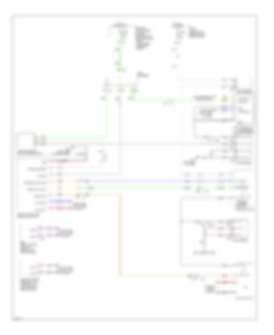
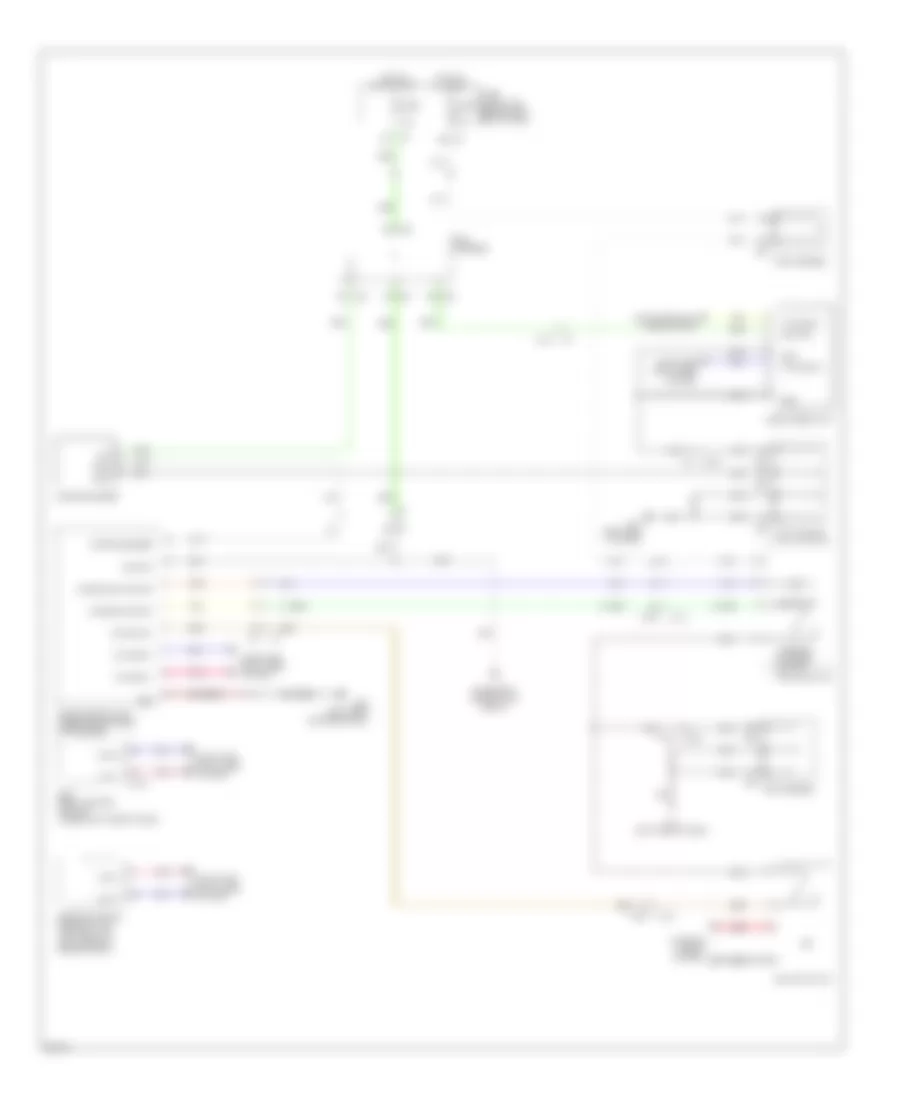
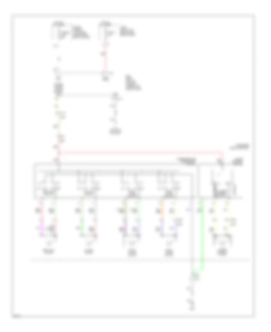
AIR CONDITIONING
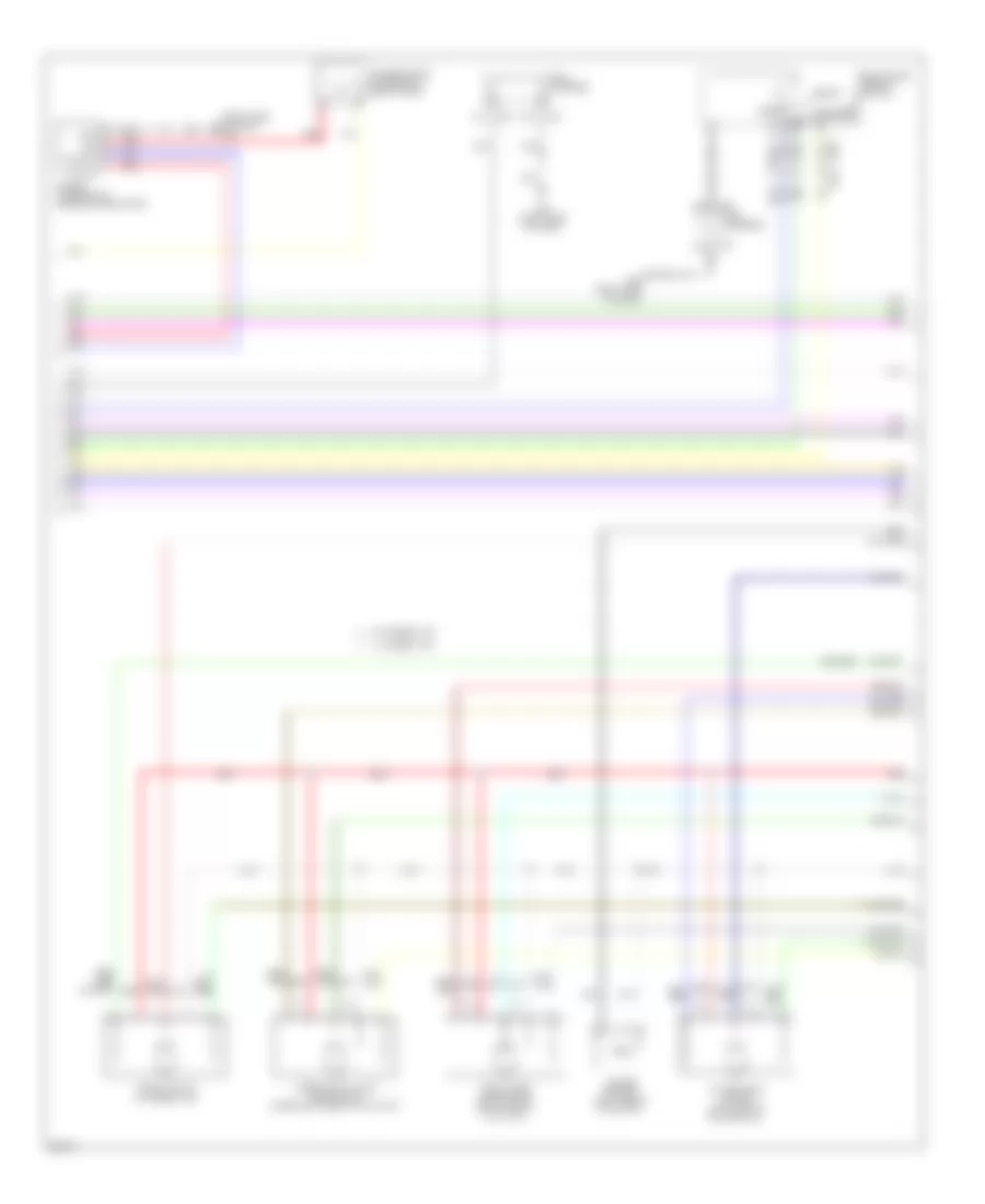
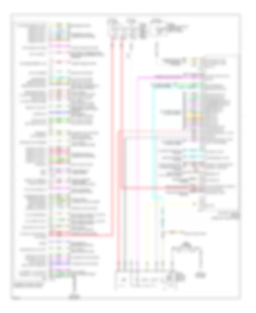
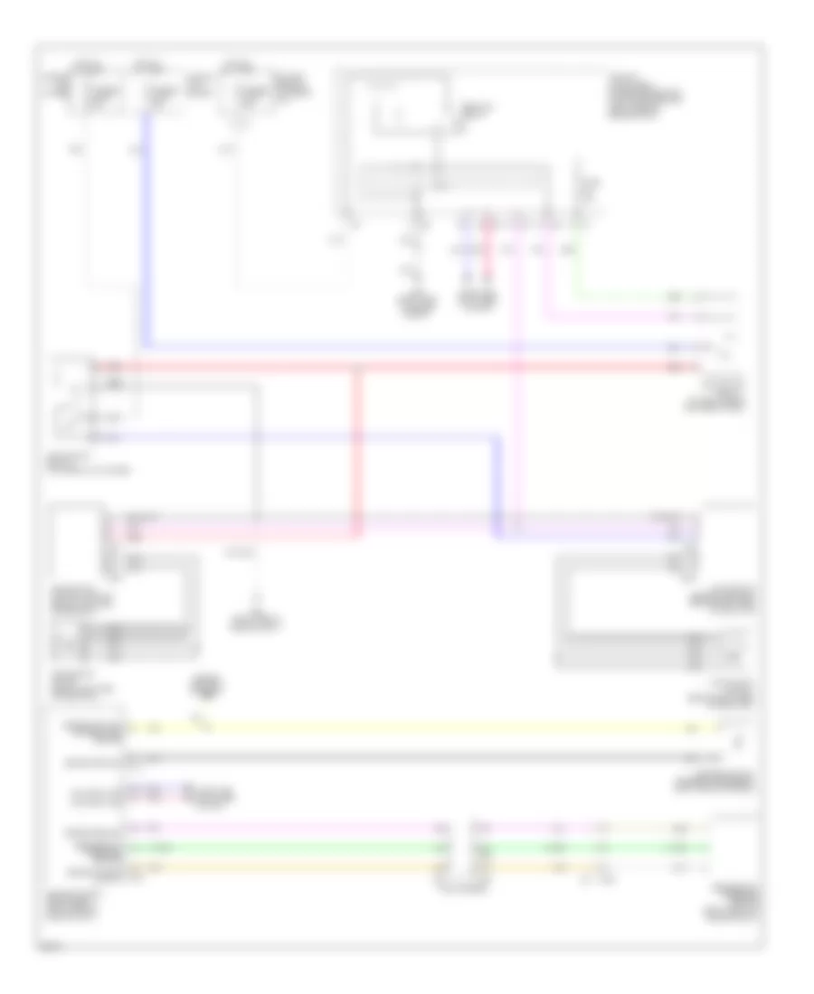
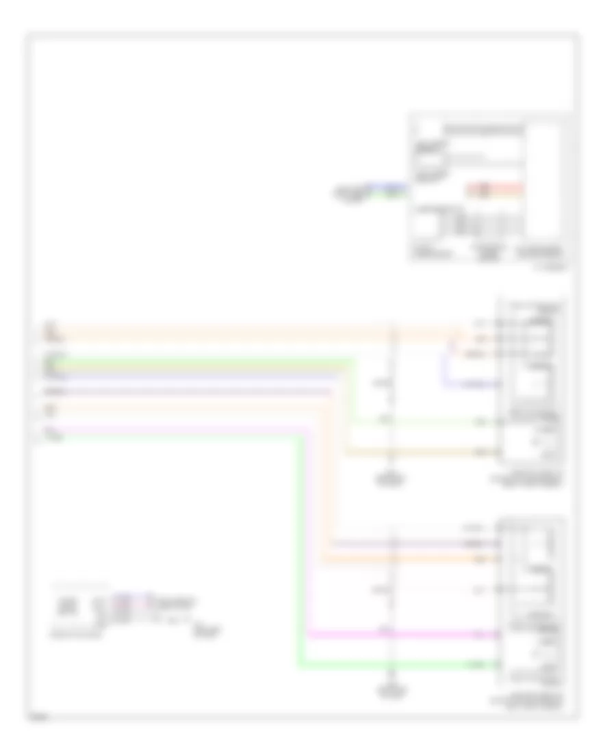
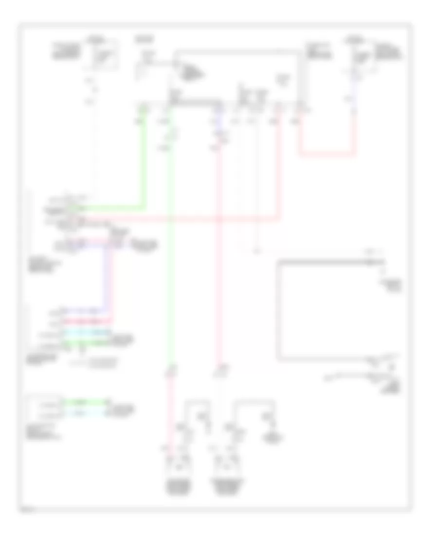
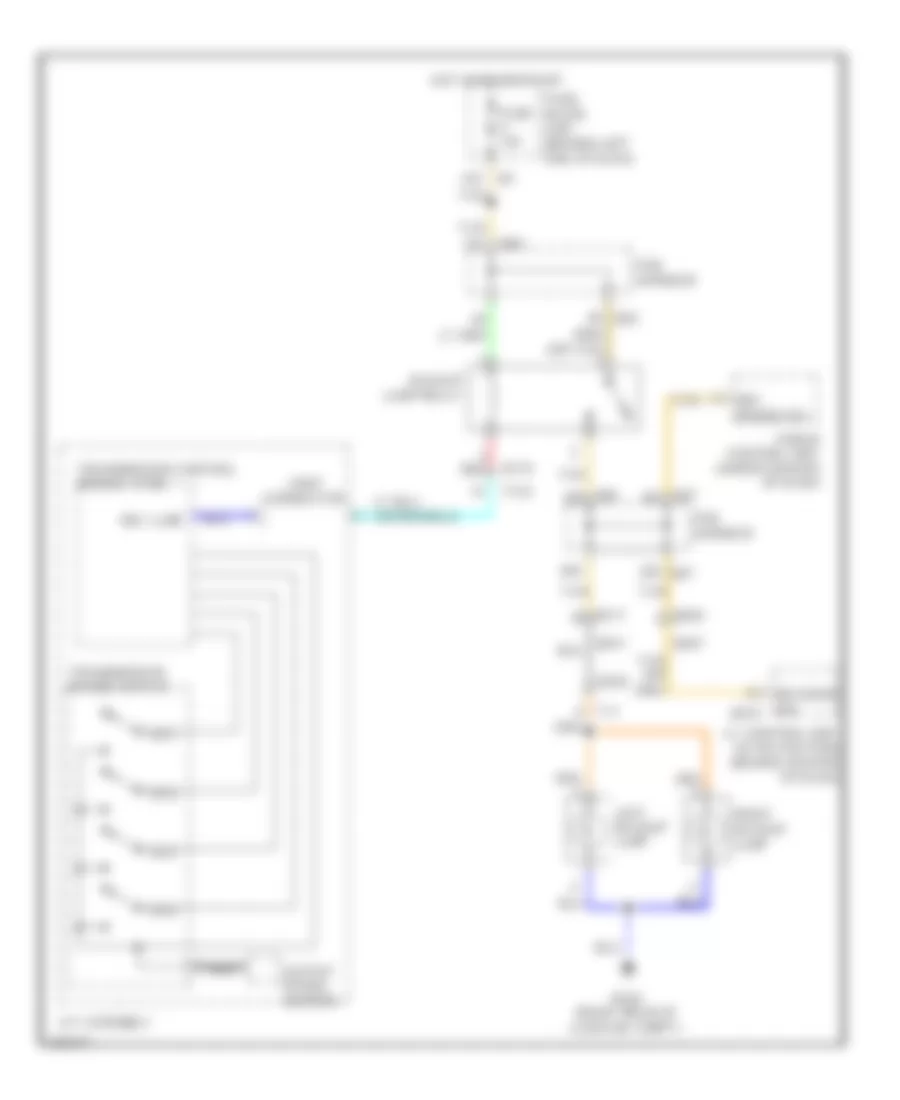
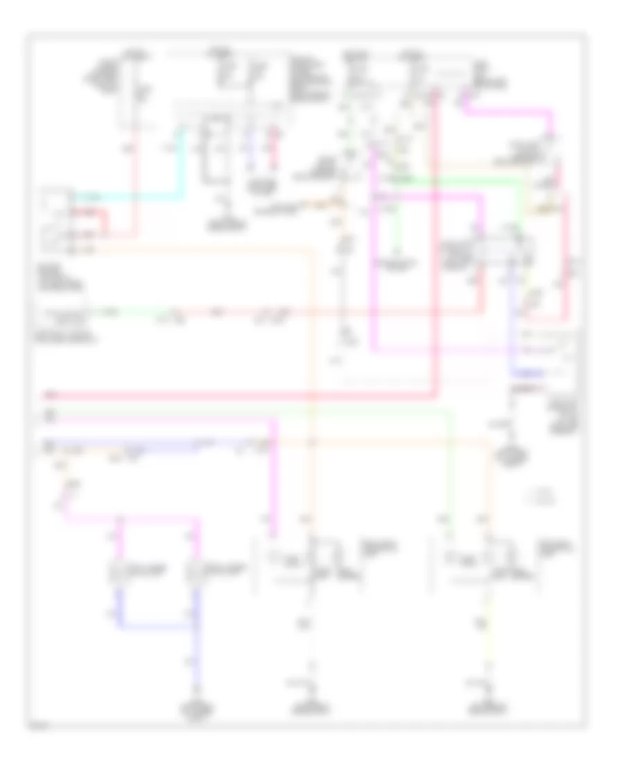
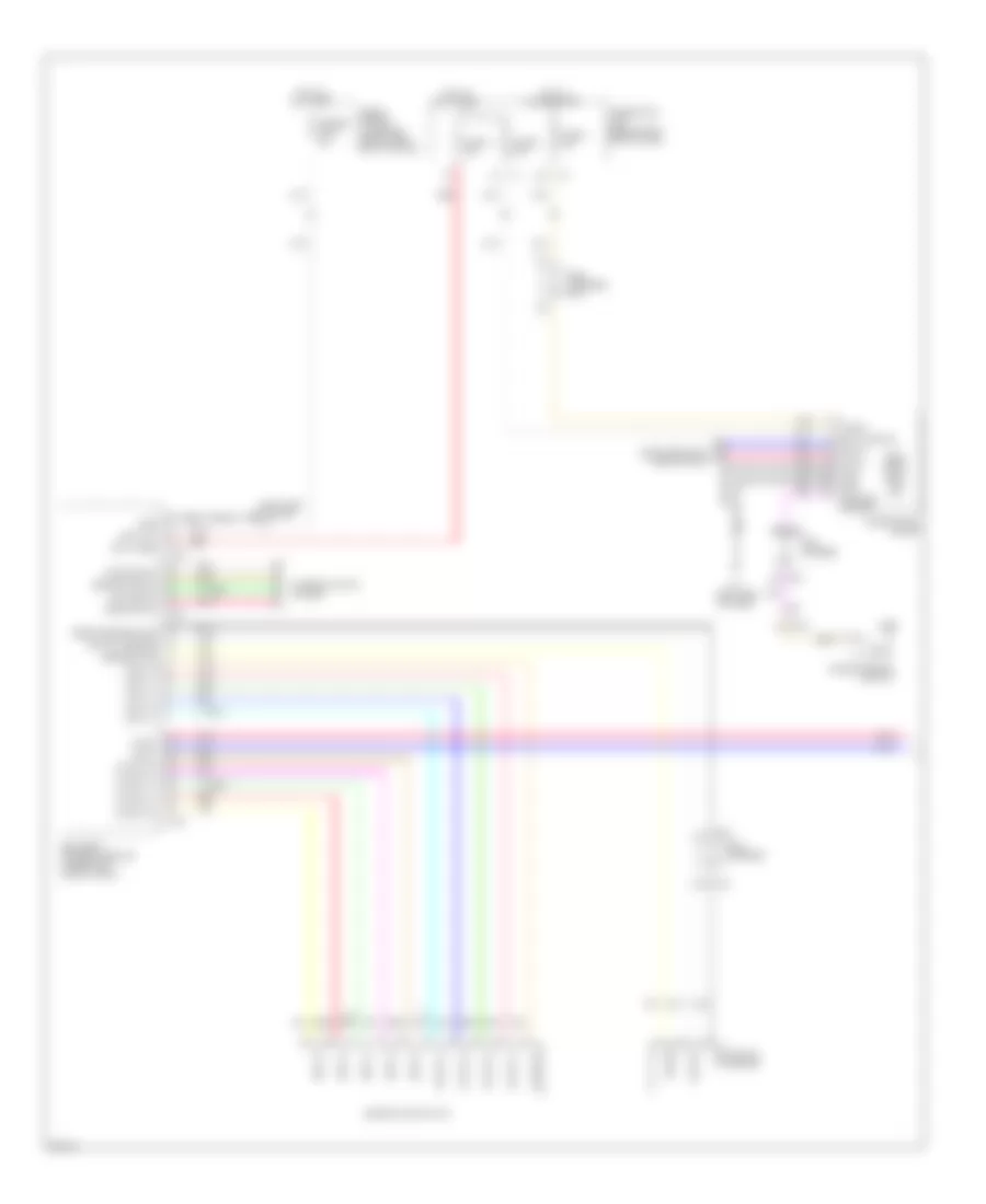
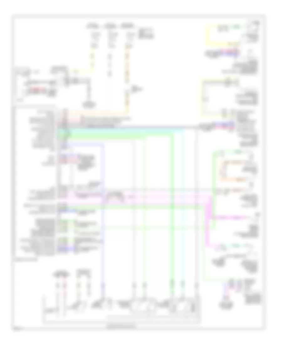
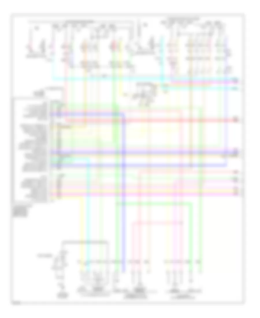
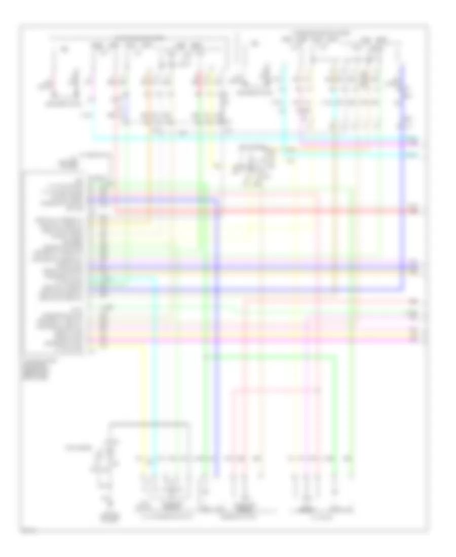
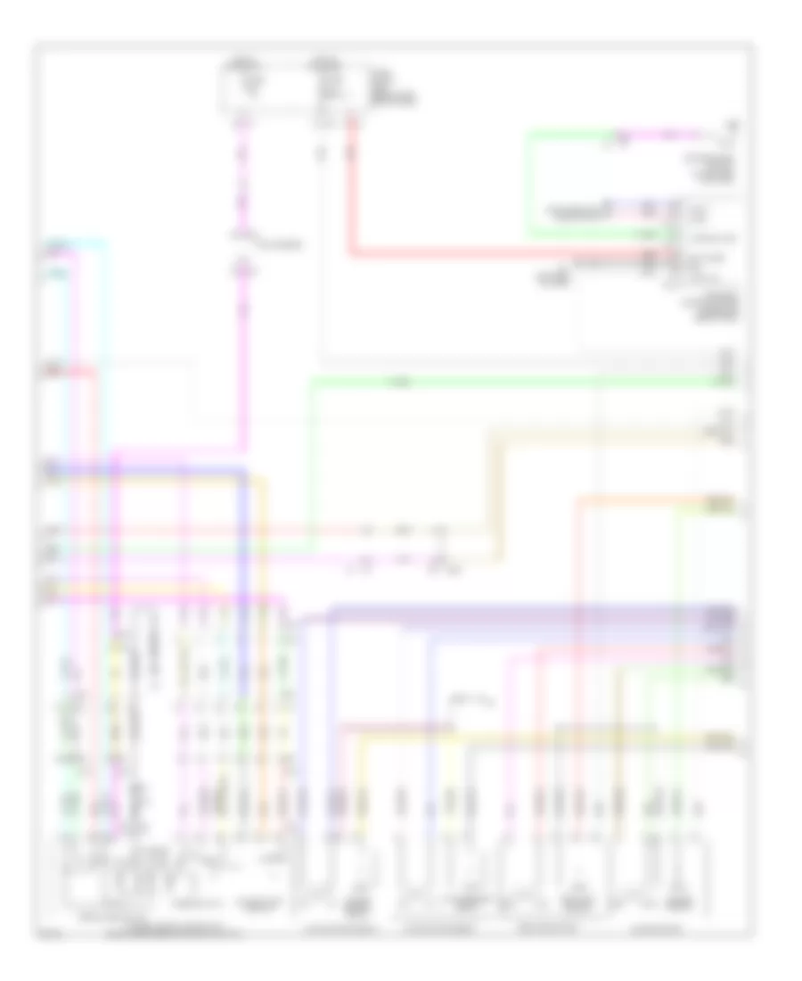
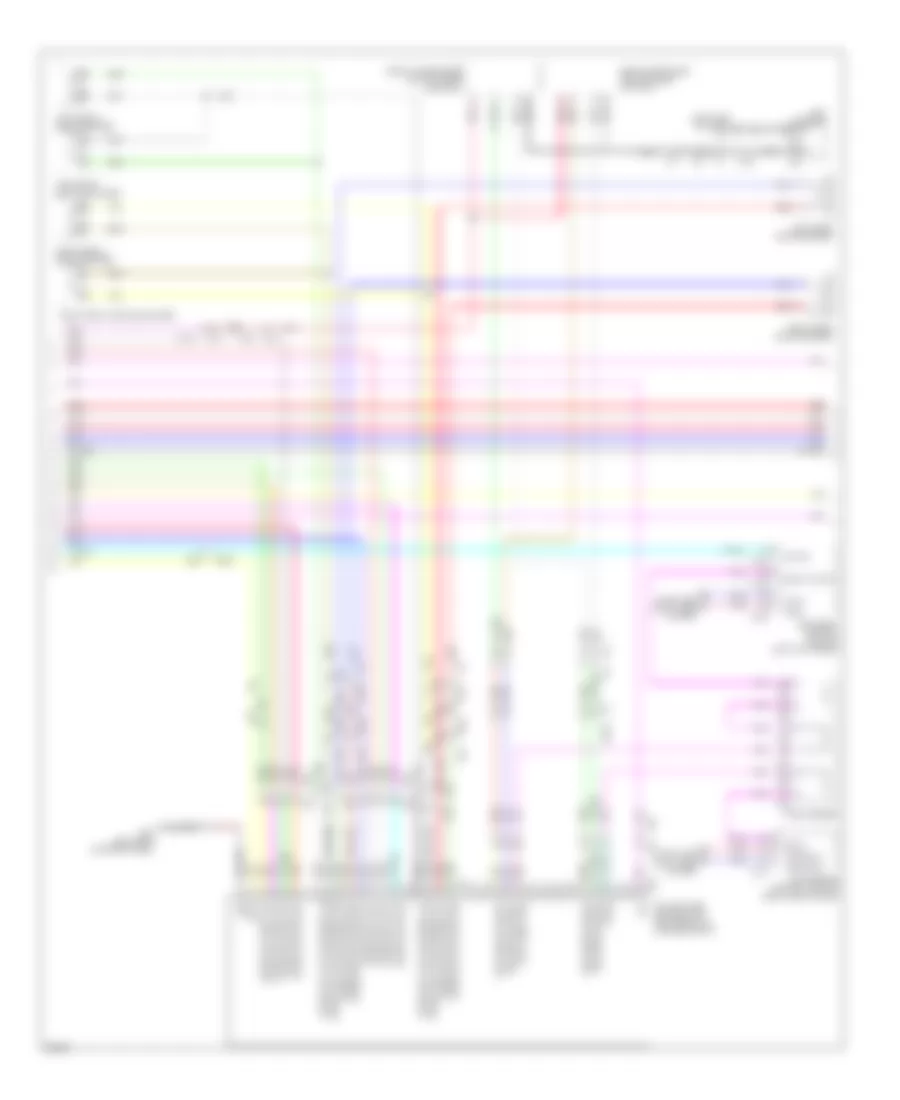
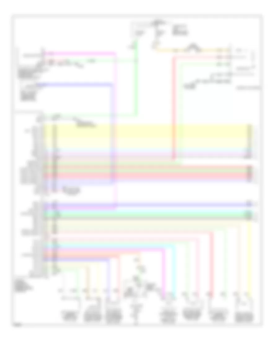
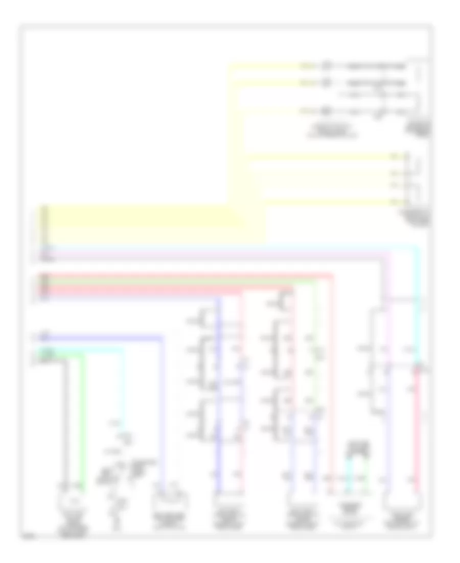
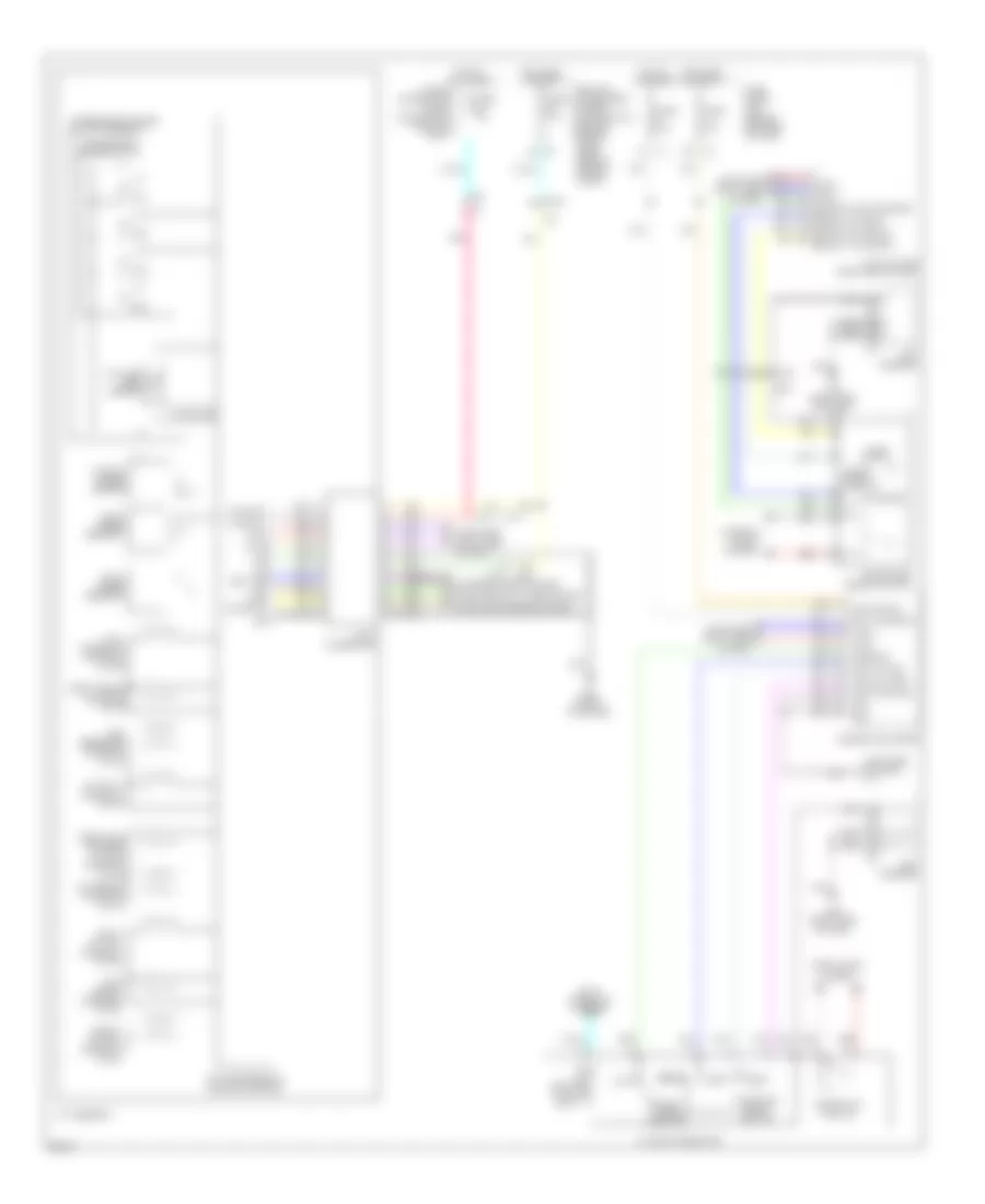
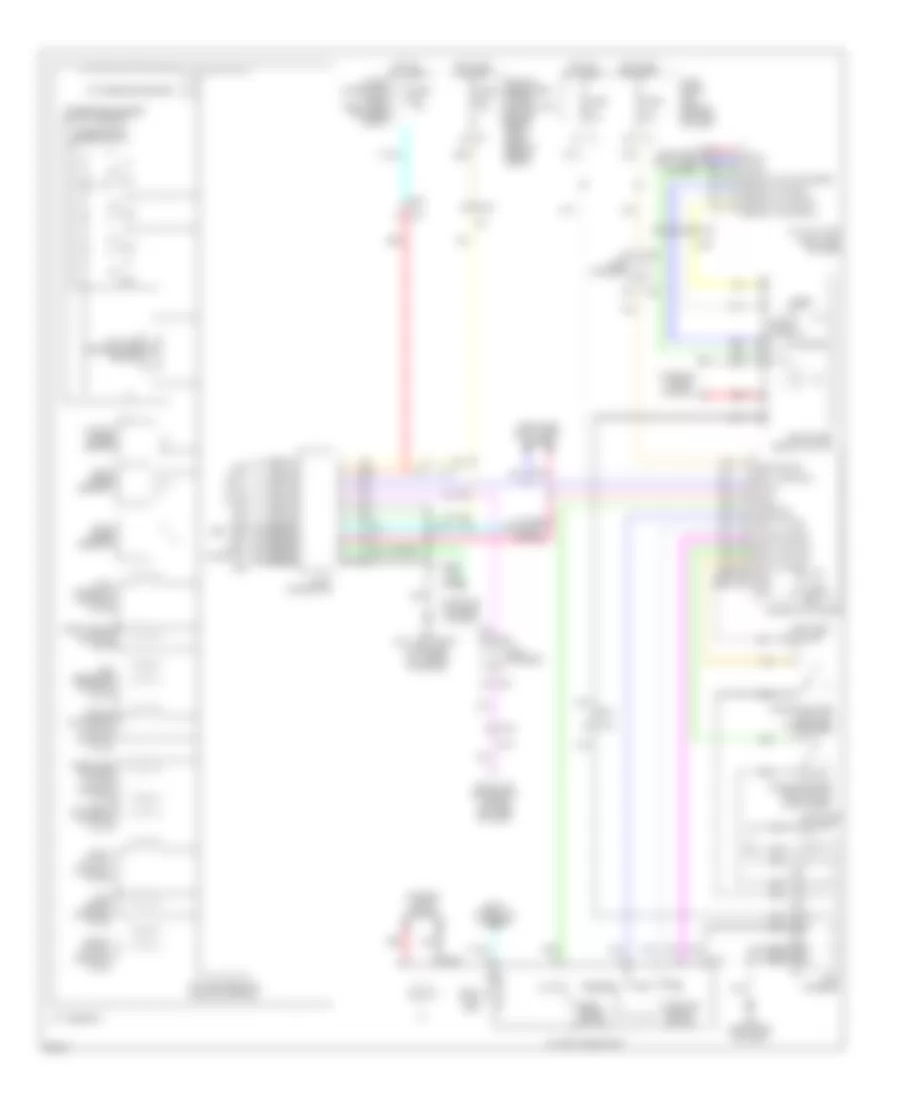
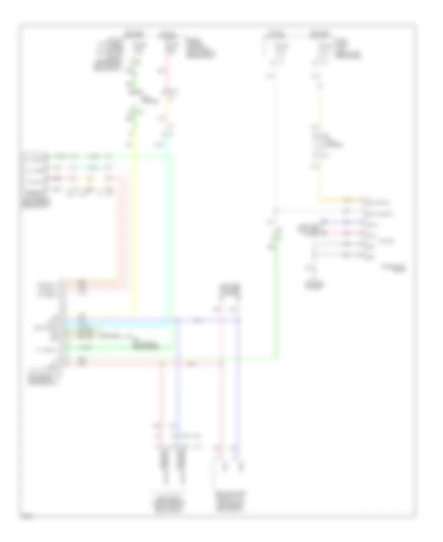
3.5L HYBRID
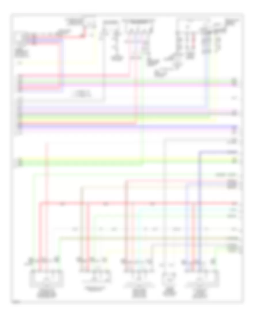
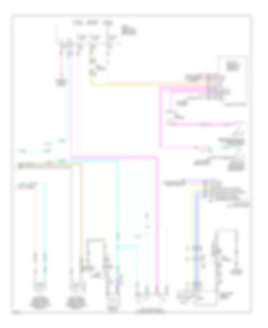
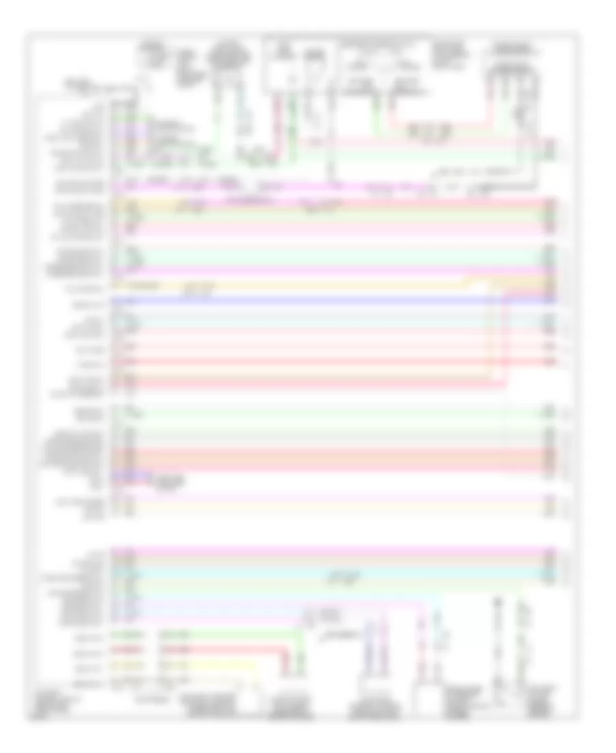
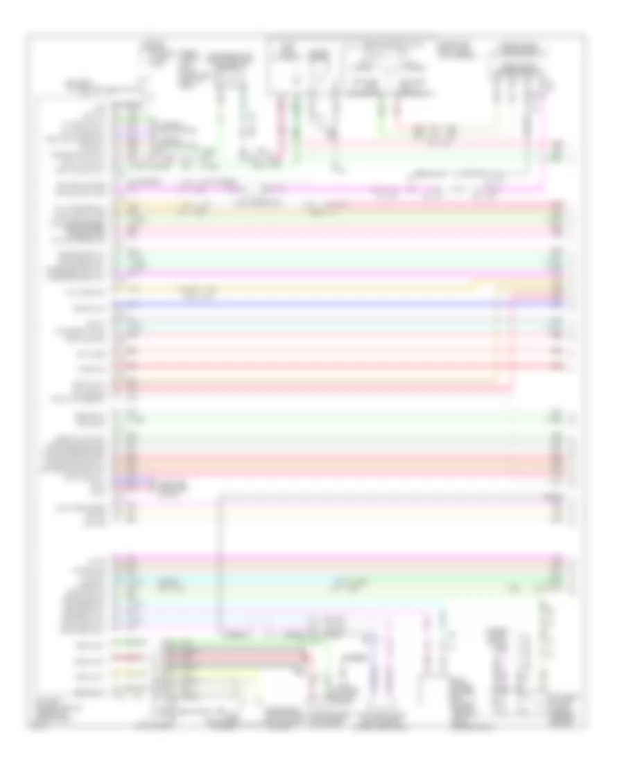
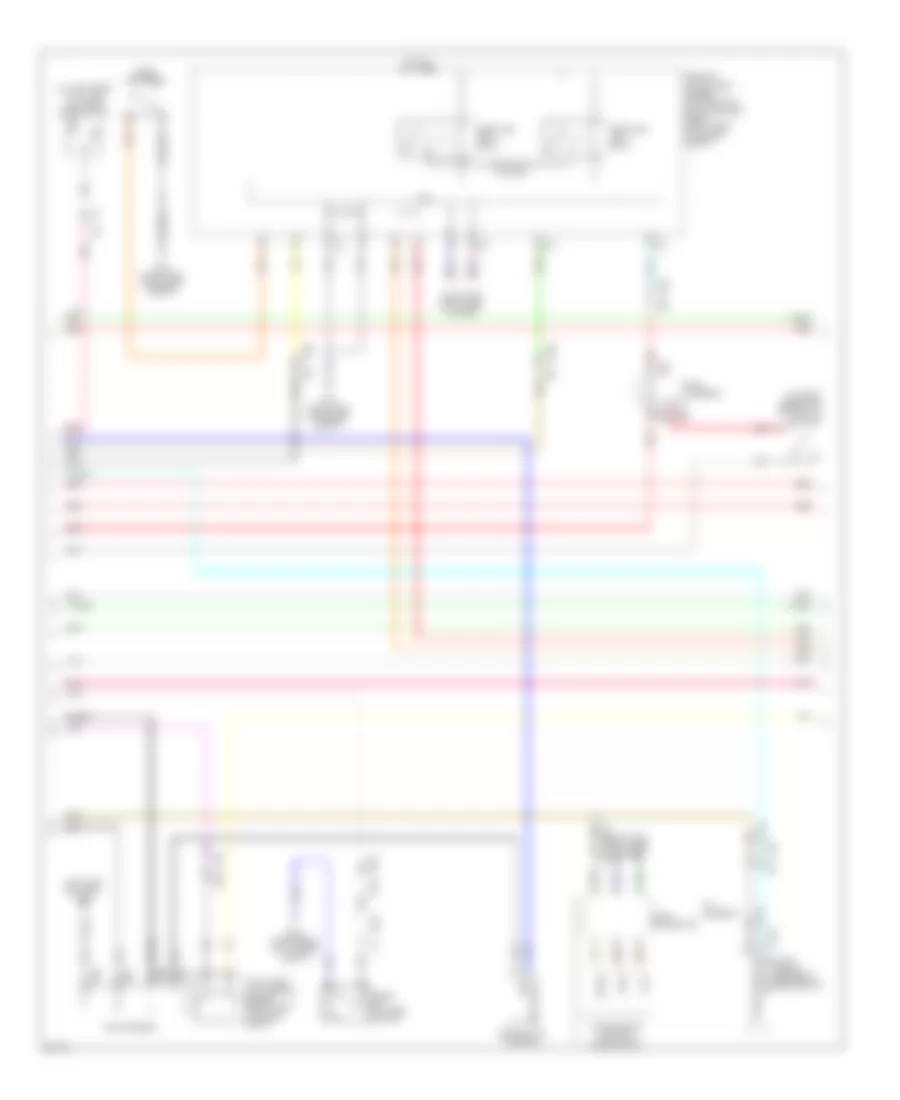
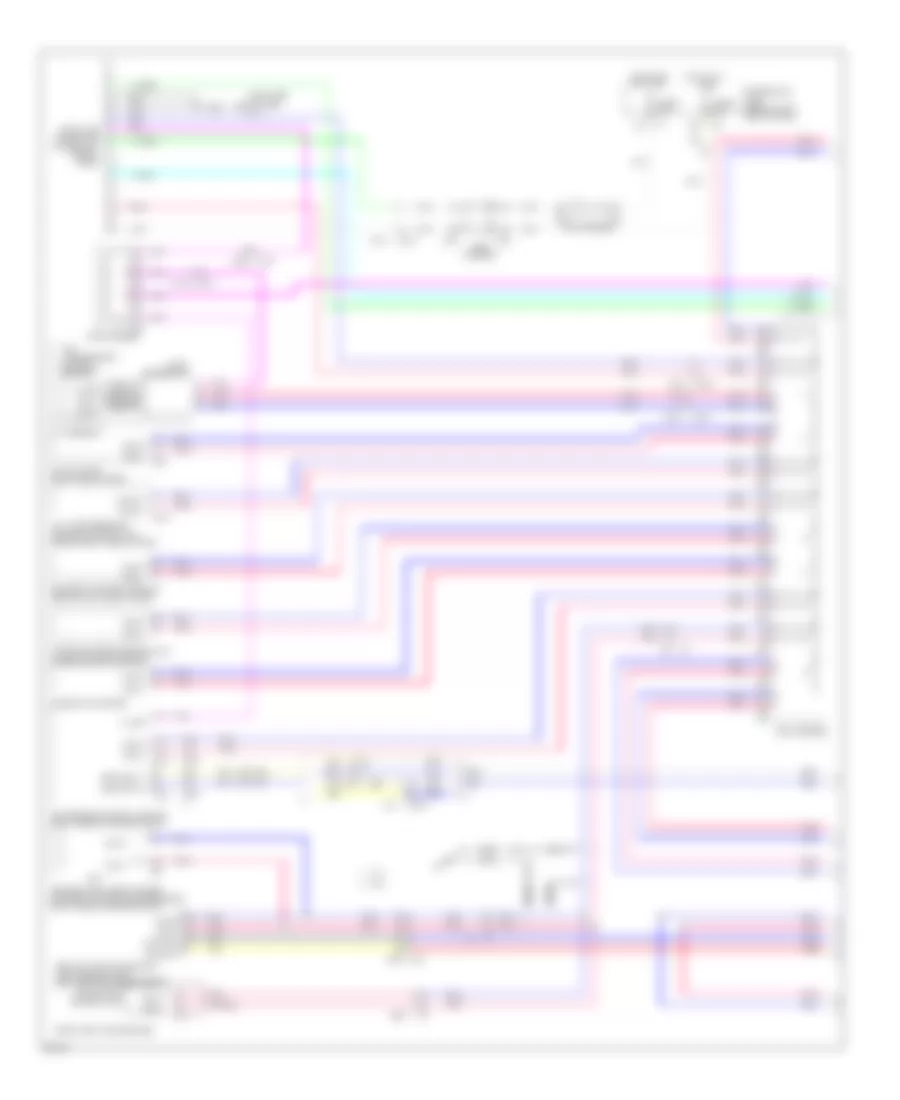
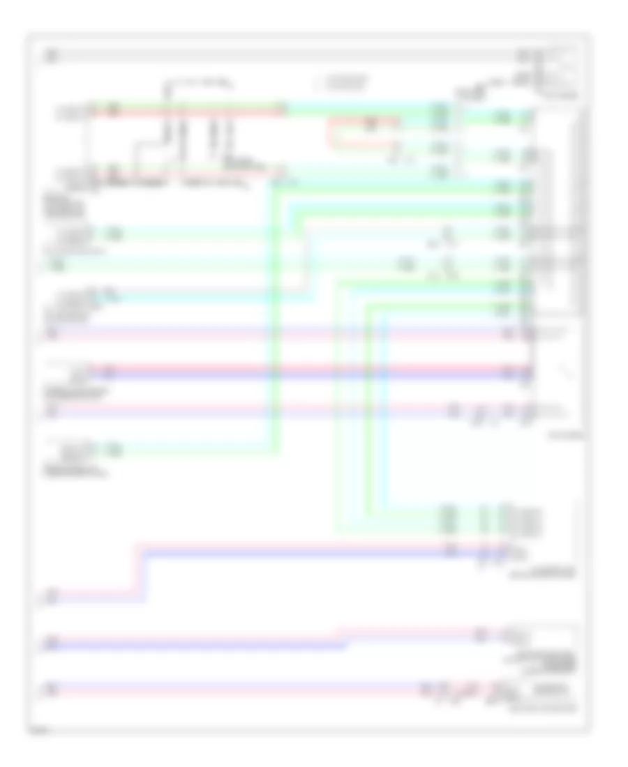
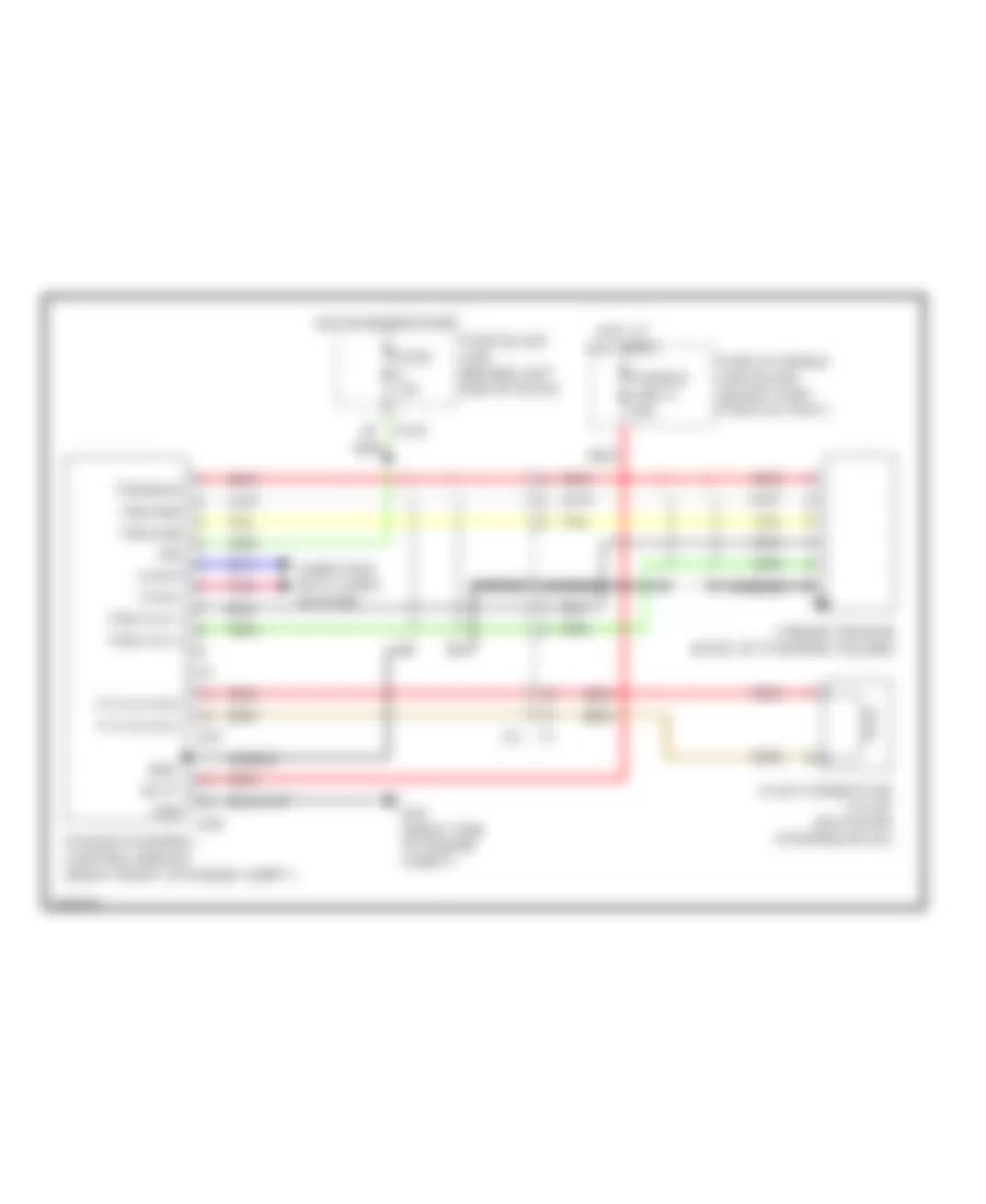
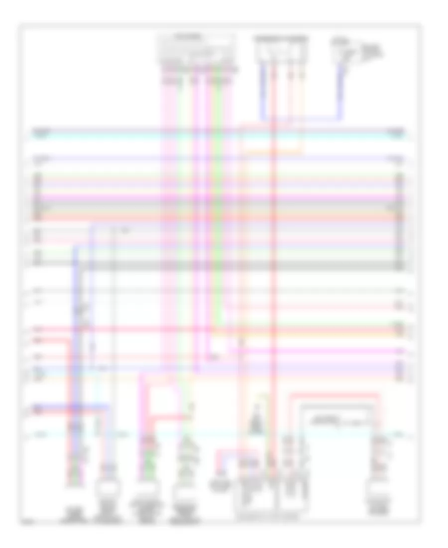
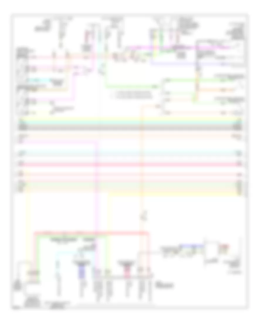
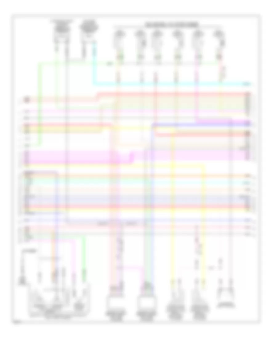
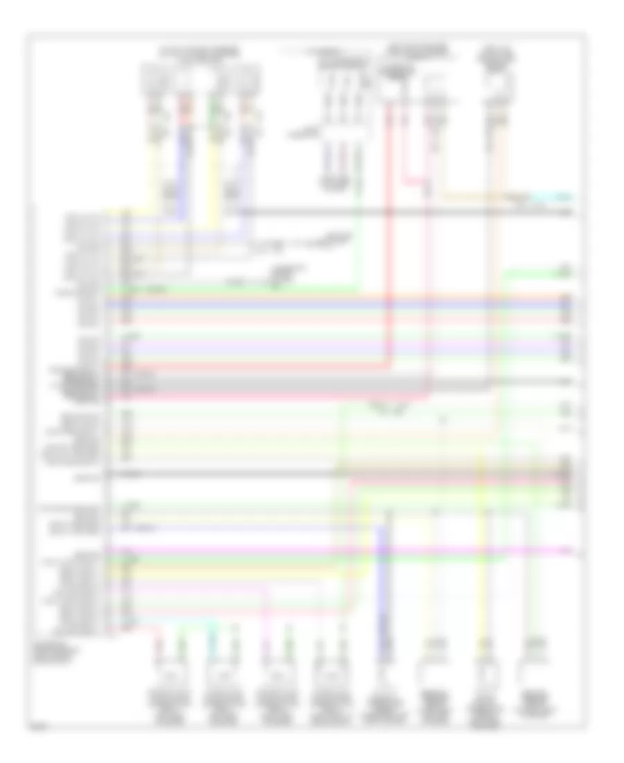
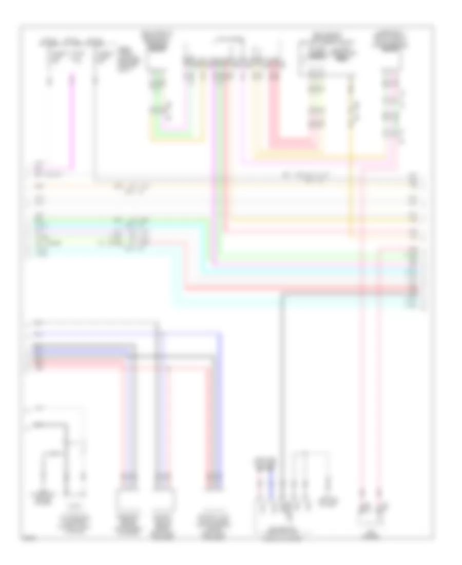
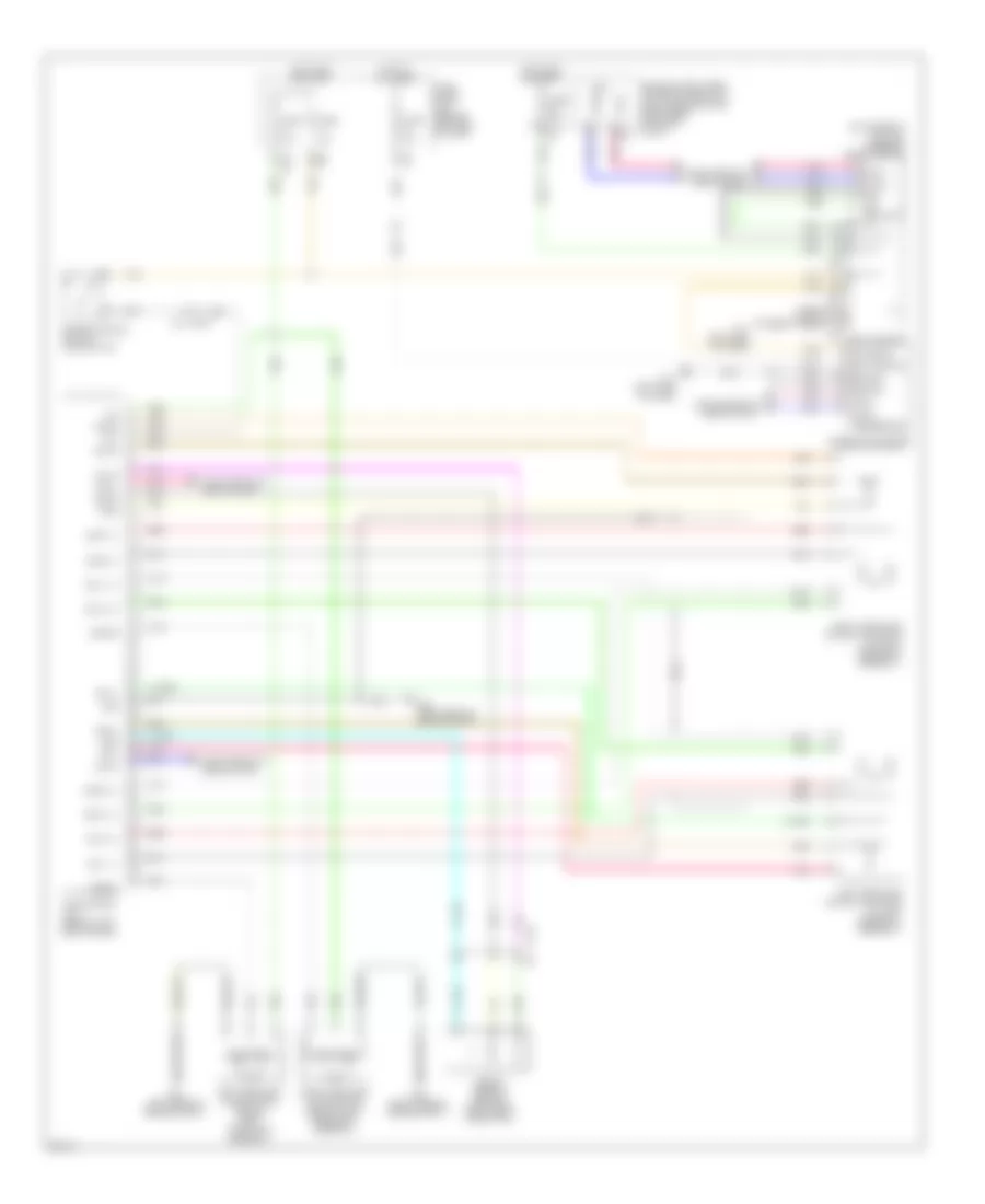
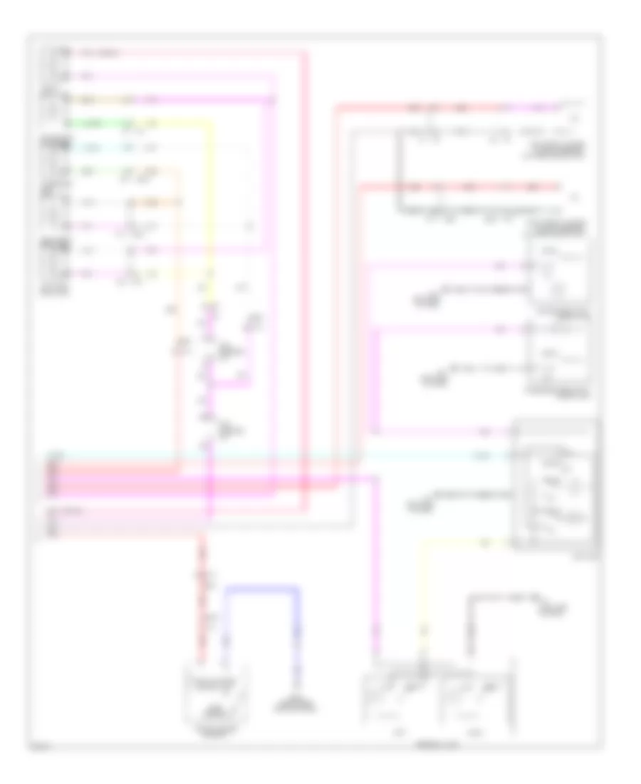
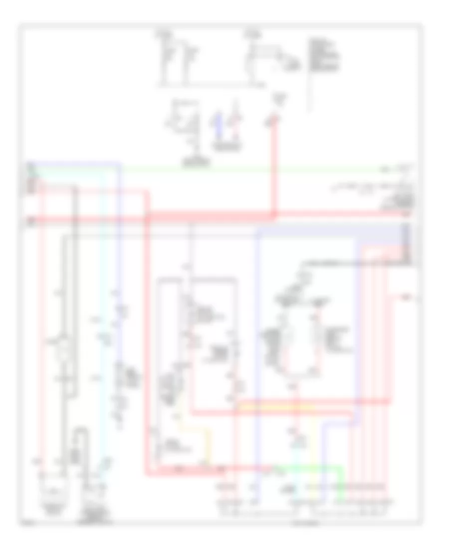
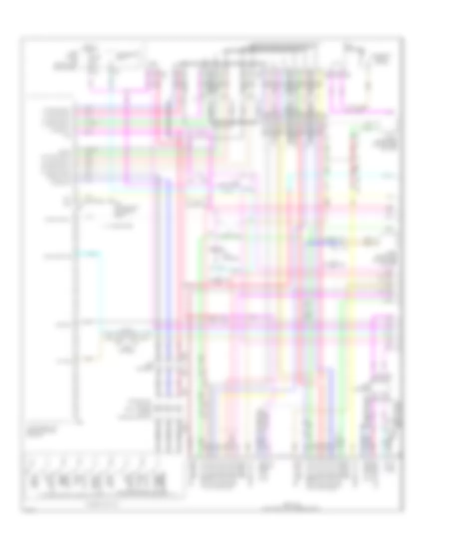
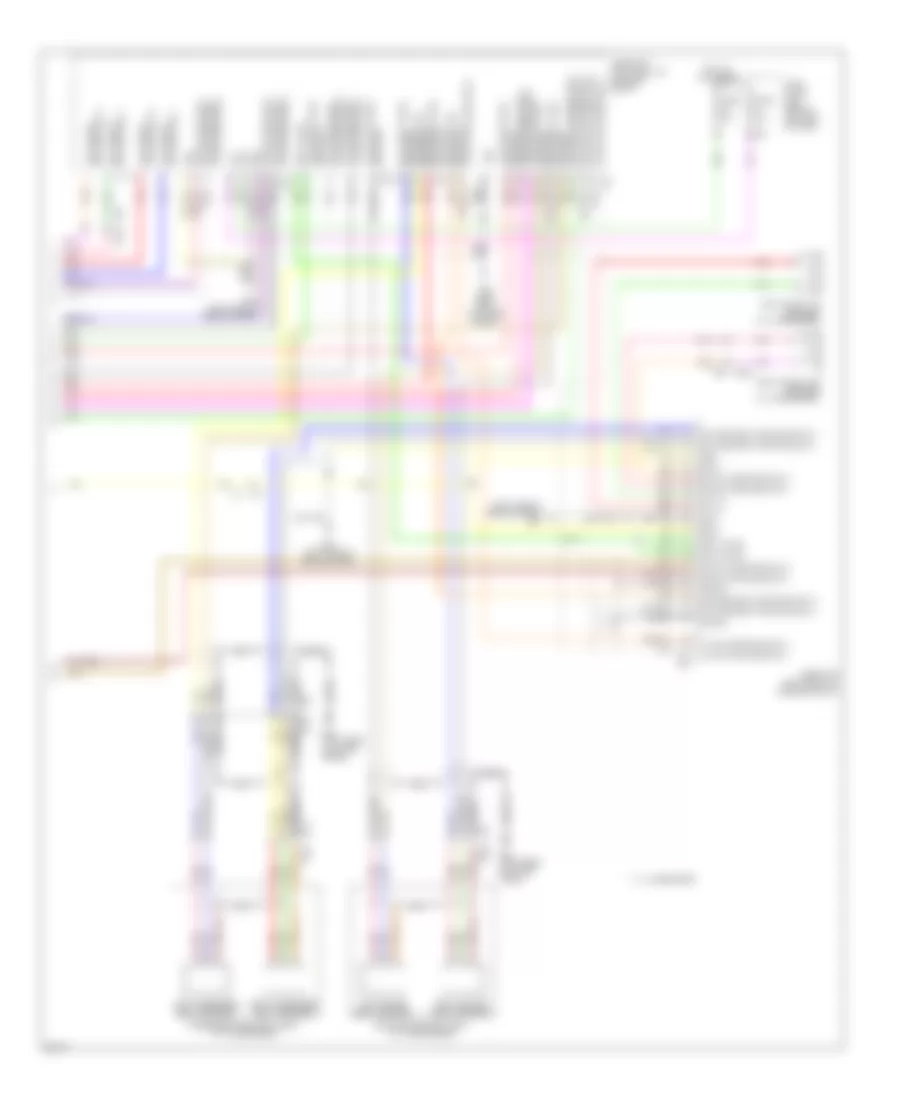
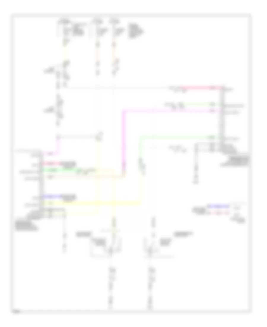
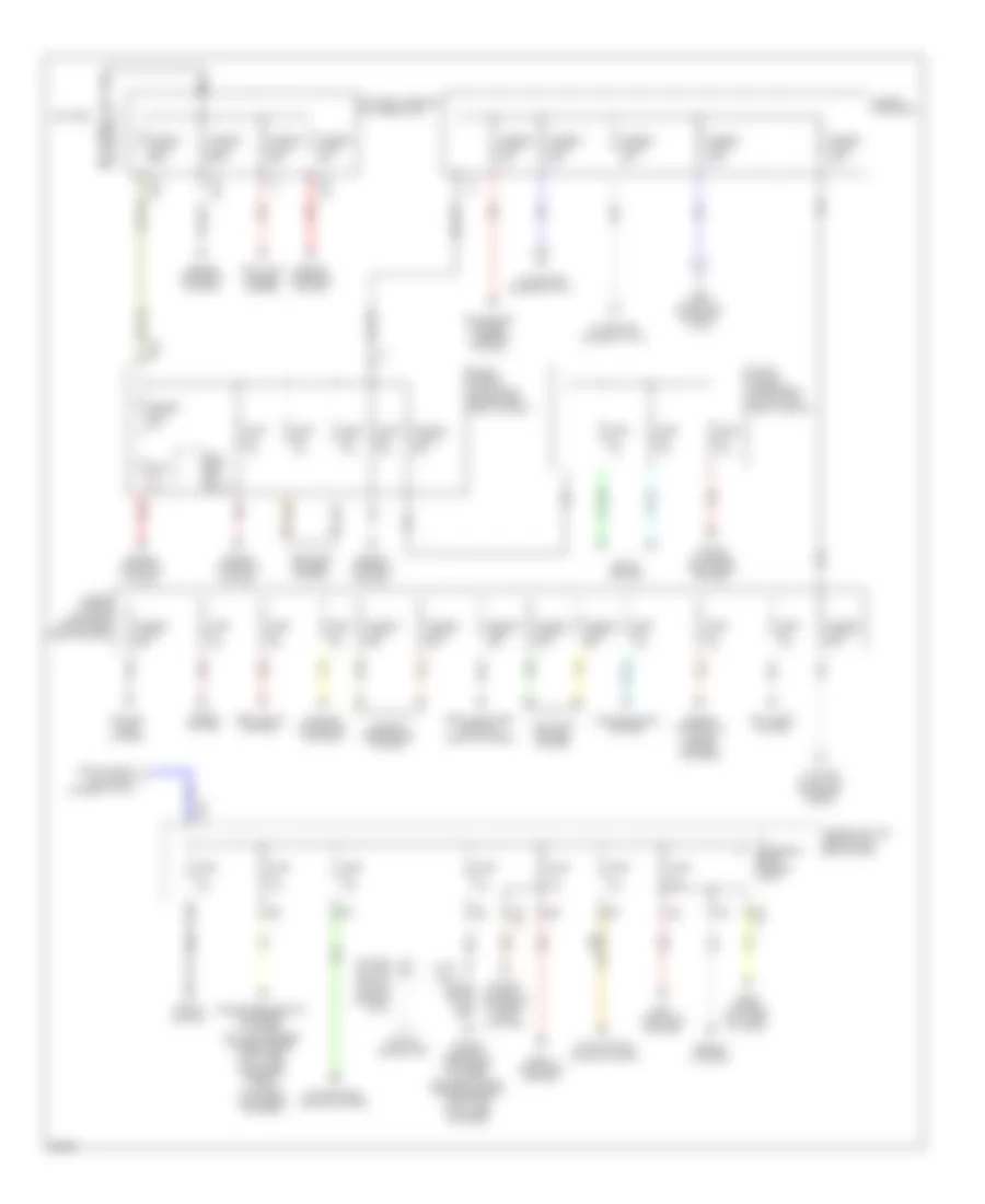
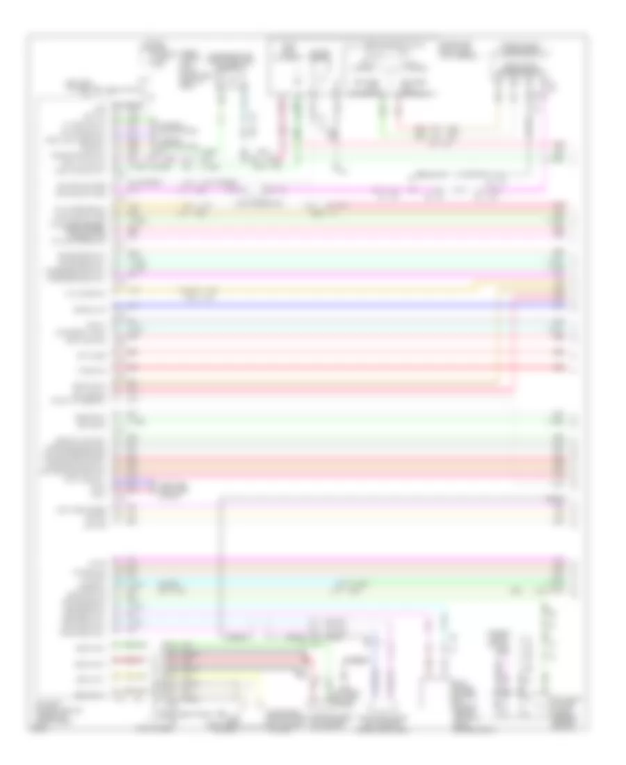
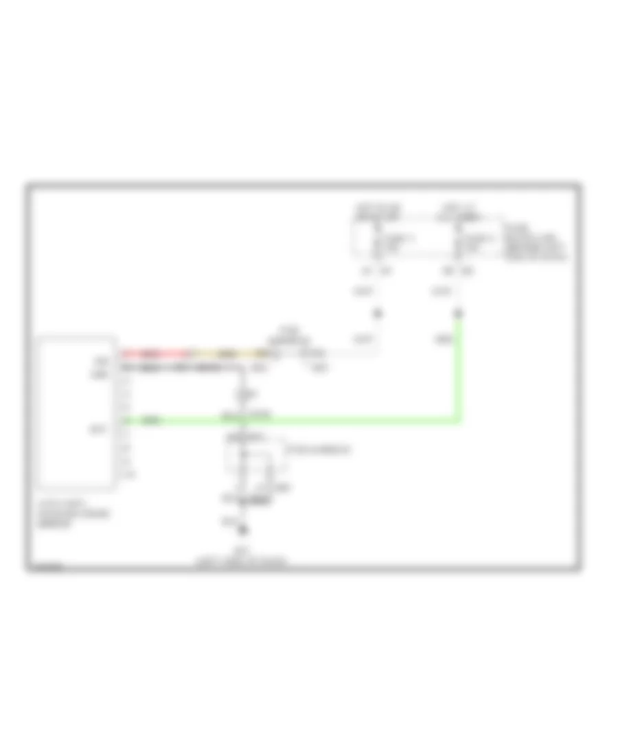
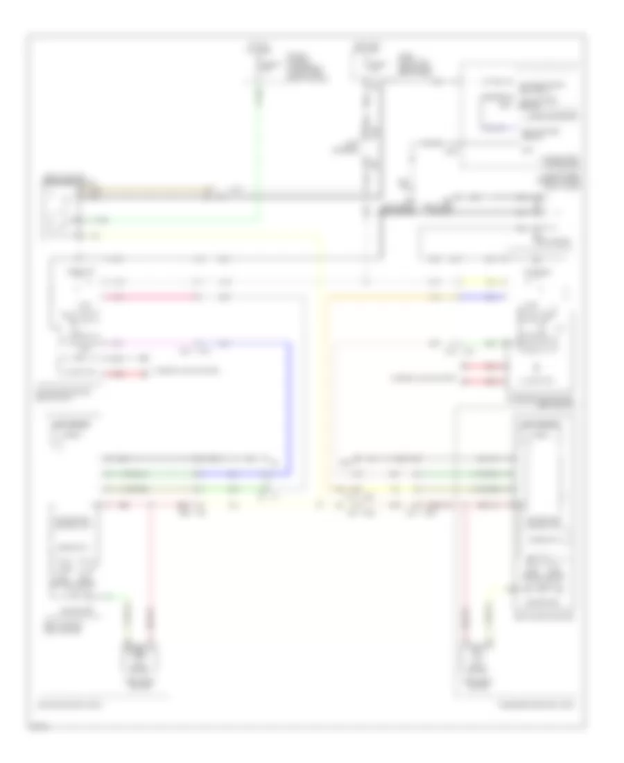
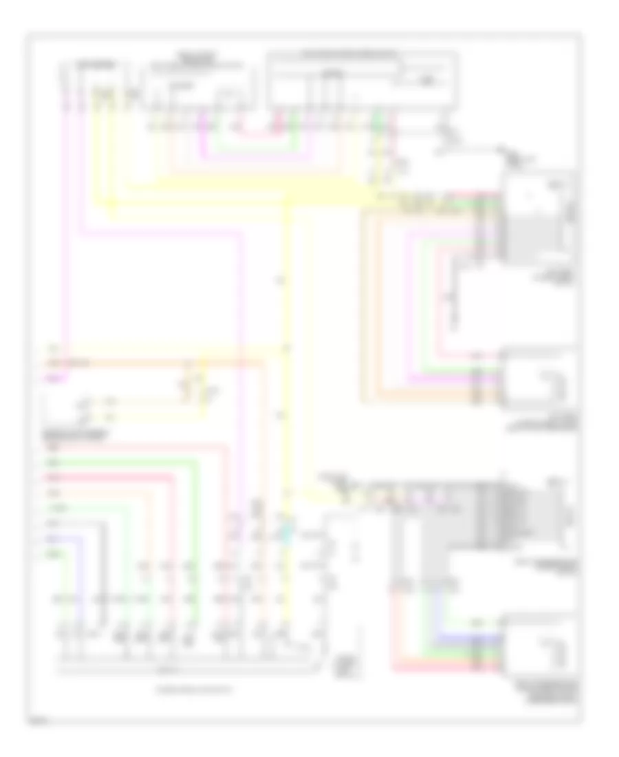
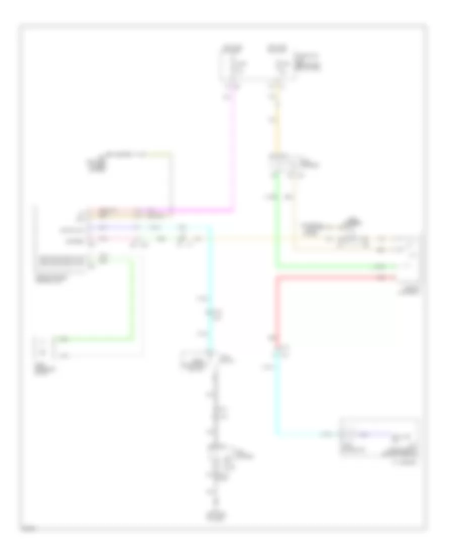
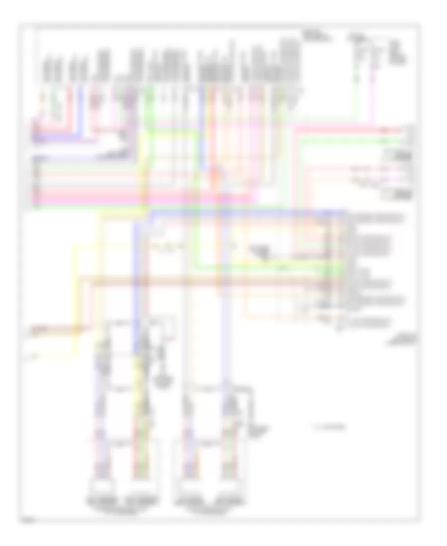
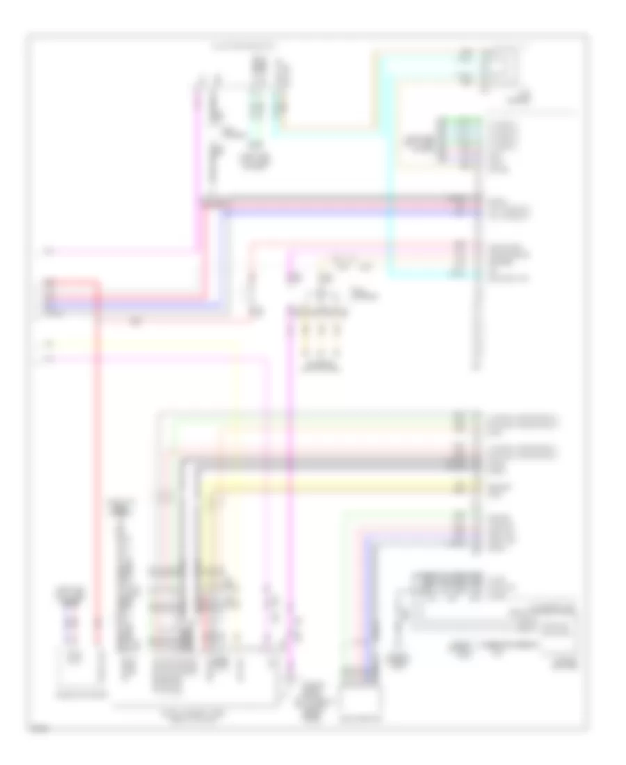
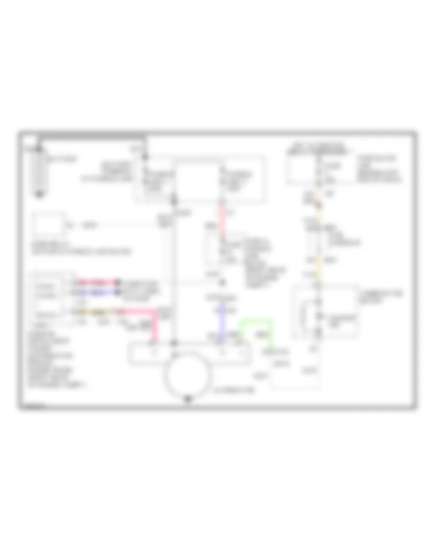
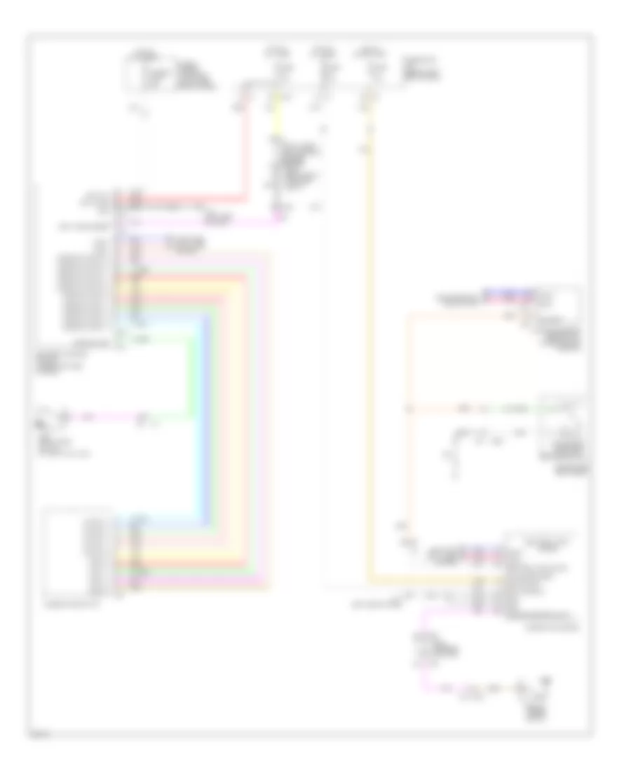
3.5L Hybrid, Automatic A/C Wiring Diagram (1 of 4) for Infiniti Q70 5.6 2014

List of elements for 3.5L Hybrid, Automatic A/C Wiring Diagram (1 of 4) for Infiniti Q70 5.6 2014:
- (left side of dash) m11
- (under left side of dash) bcm (body control module)
- 10f
- A/c auto amp (right end of dash)
- Acc pwr sply
- Ambie sens sig
- Ambient sensor (front center of engine compt)
- Bat pwr sply
- Blower relay
- Blwr mtr f/b sig
- Blwr rly cont
- Can-h
- Can-l
- Combination meter
- Computer data lines system
- Detecting sens sig
- Drv mode select sw (eco)
- Drv mode select sw (snow)
- Drv mode select sw (sport)
- Drv mode select sw (standard)
- E101 1d
- E103 6f
- E106
- E33
- Exh gas/outside odor
- Fuse 10a
- Fuse 15a
- Fuse block (j/b) (behind left end of dash)
- Fusible link block
- Fusible link r 100a
- Gnd
- H/p cont sig
- Heated str whl rl ctrl sig
- Heated str whl sw sig
- Hot at all times
- Hot in acc or on
- Hot in on or start
- Humidity sens (data) sig
- Humidity sens (sck) sig
- Humidity sens gnd
- Humidity sens sig
- Humidity sensor (w/ forest air) (top center of windshield)
- Ign pwr sply
- In-vehicle sens sig
- In-vehicle sensor (lower left side of dash)
- Inside odor detecting sens sig
- Ionizer ctrl sig
- M1 2a
- M1 3a
- M110
- M120
- M123
- M20
- M22
- M23
- M24
- M3 7c
- M30
- M66
- M67
- Pcb harness
- Pnk
- Pwr transistor ctrl sig
- Red
- Seats system
- Sens pwr sply
- Sunload sens (pass) sig
- Sunload sensor (dr) sig
- Sunload sensor (top right side of dash)
- Tan
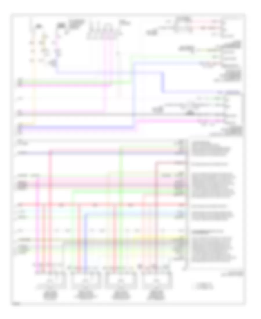
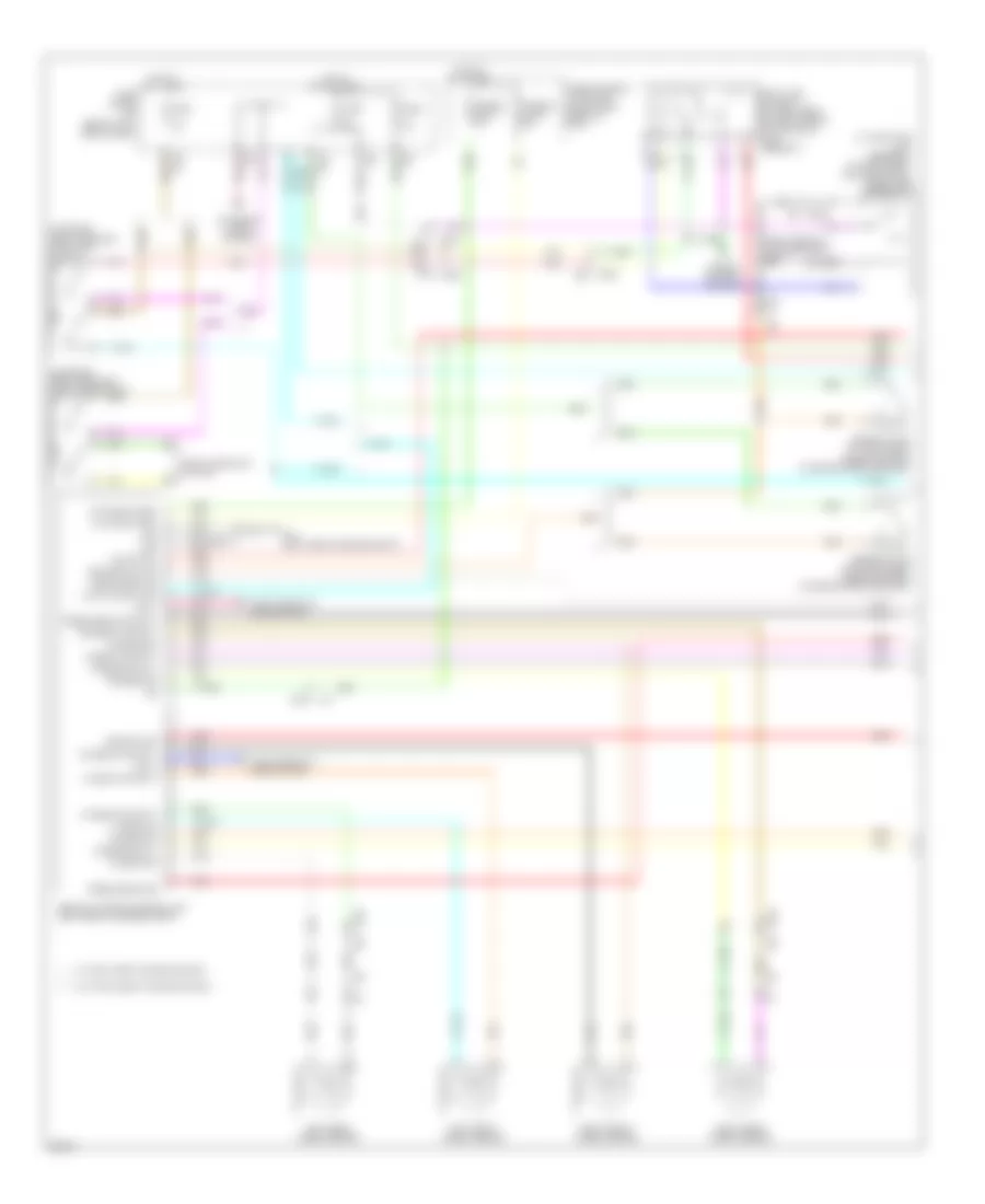
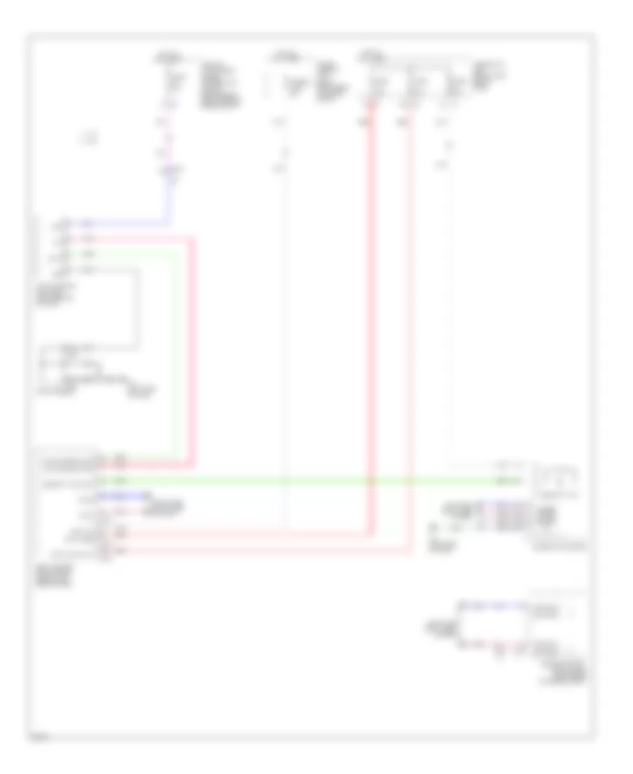
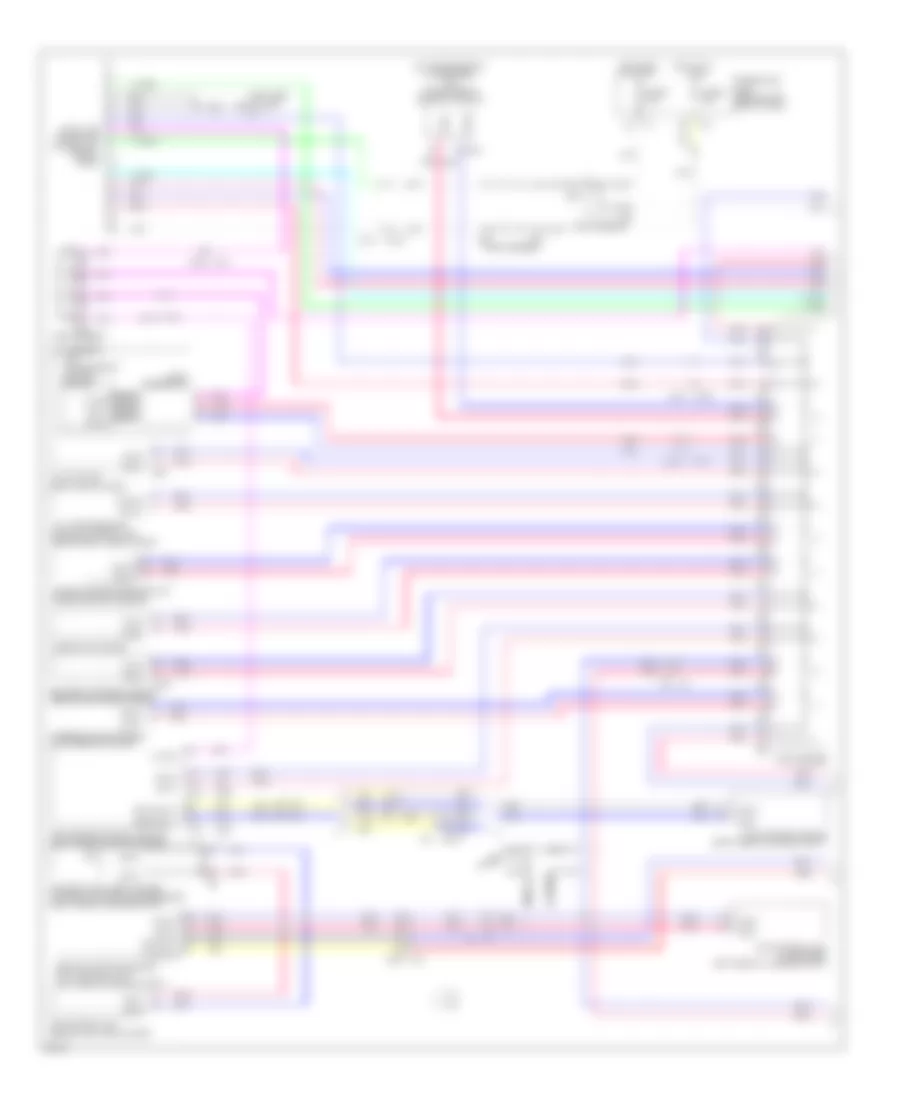
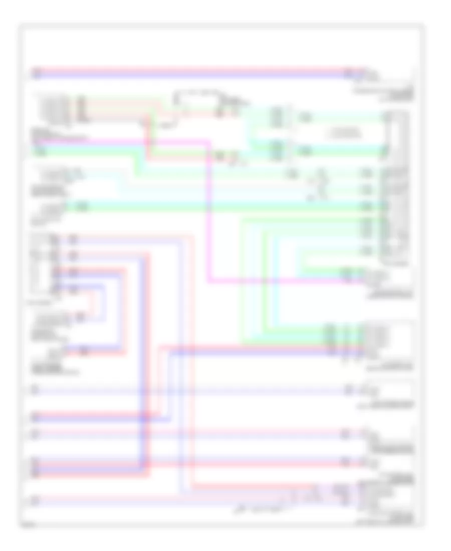
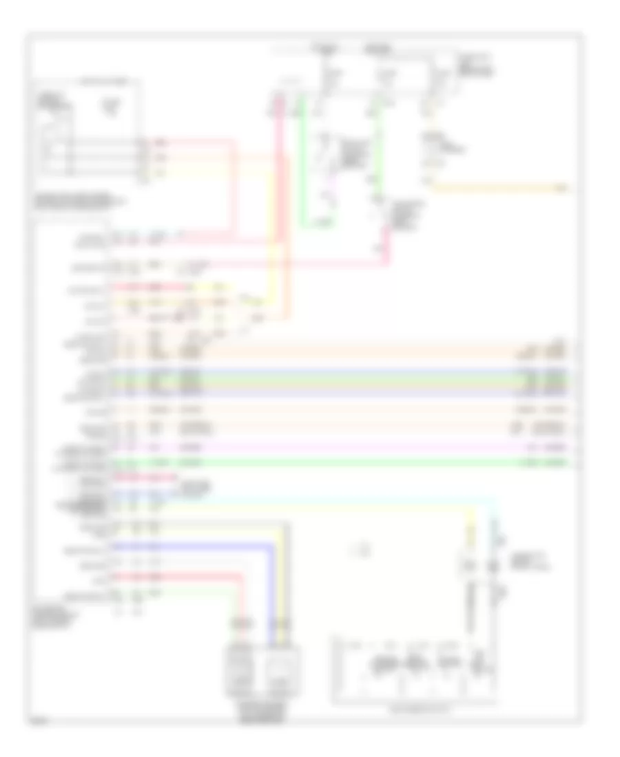
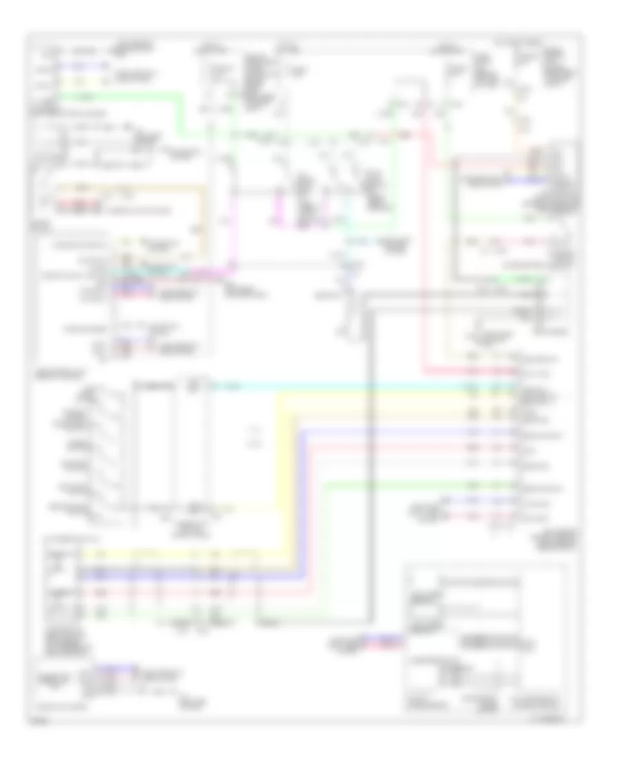
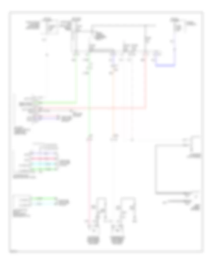
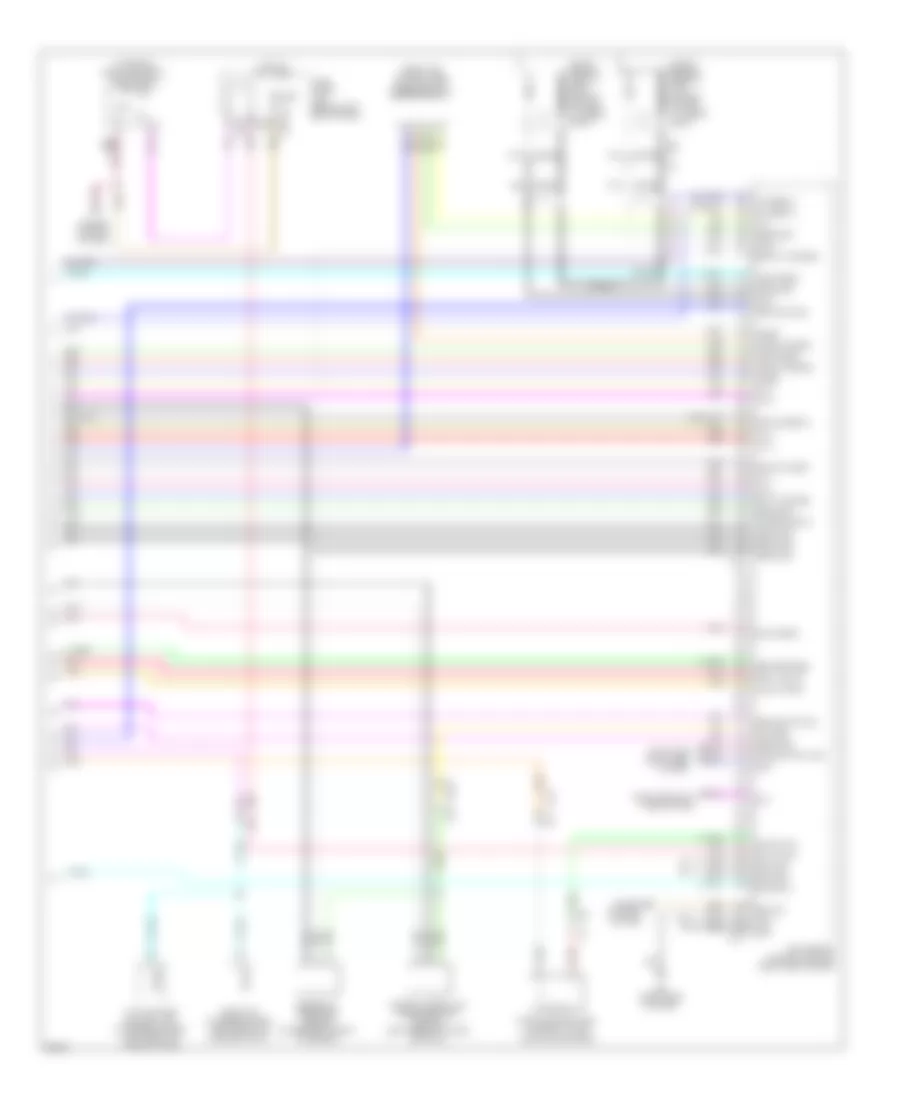
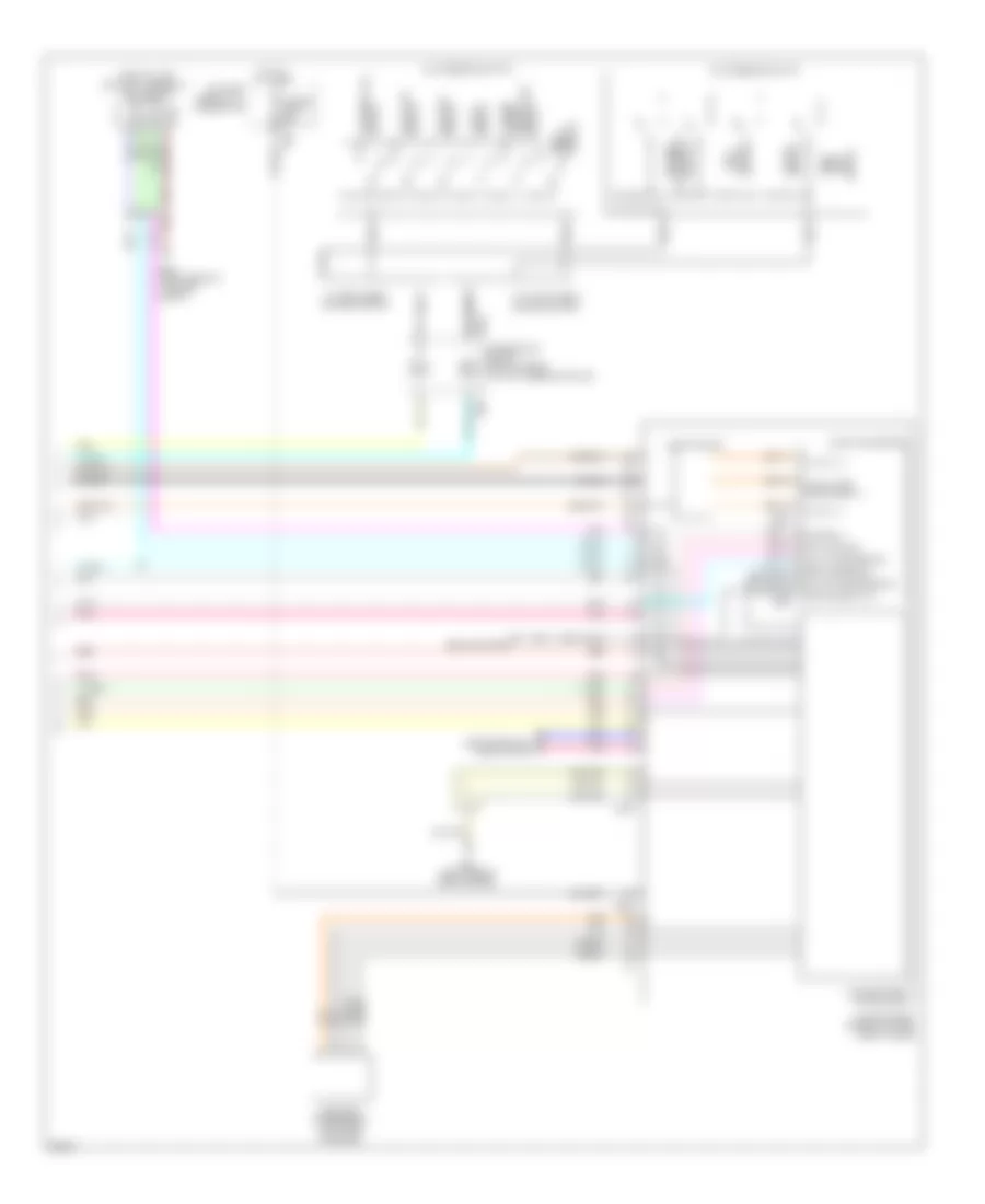
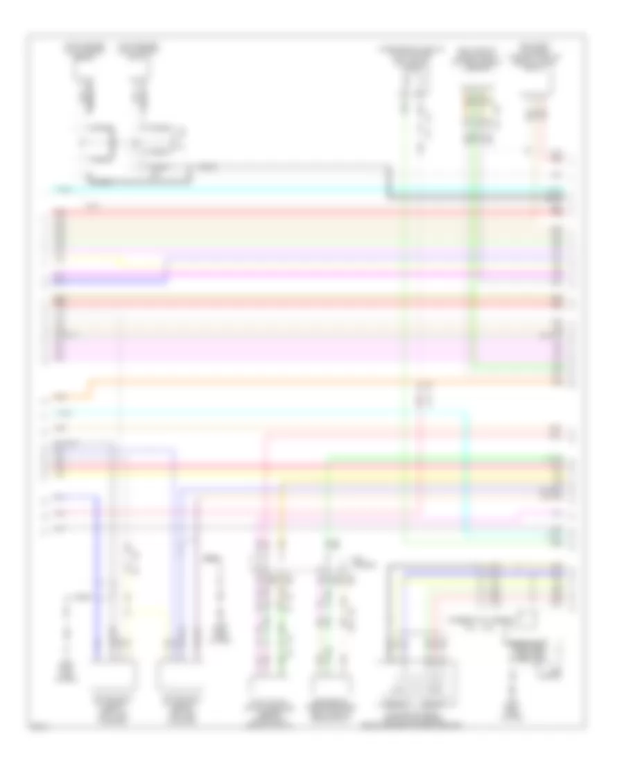
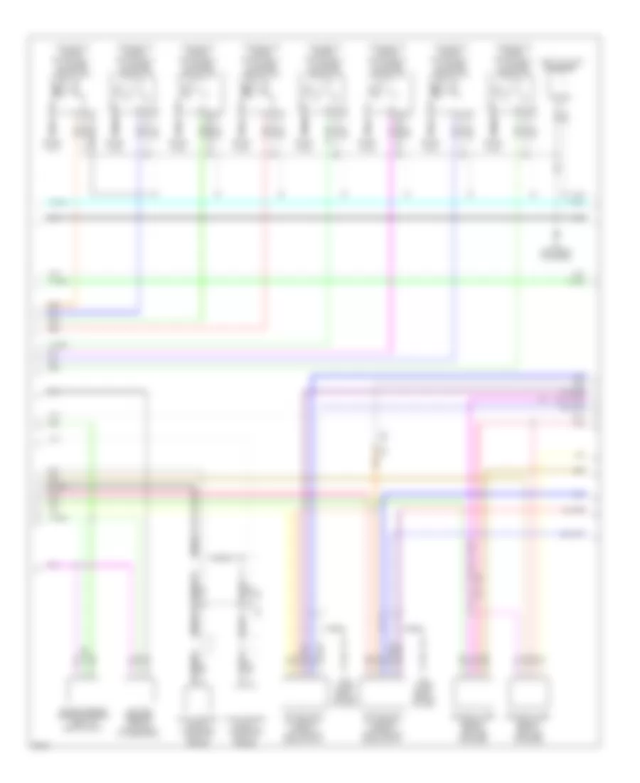
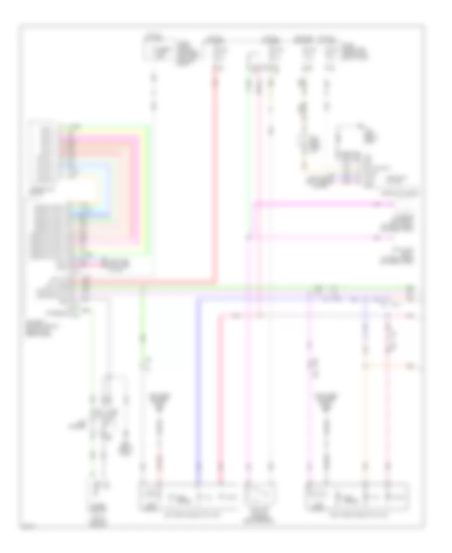
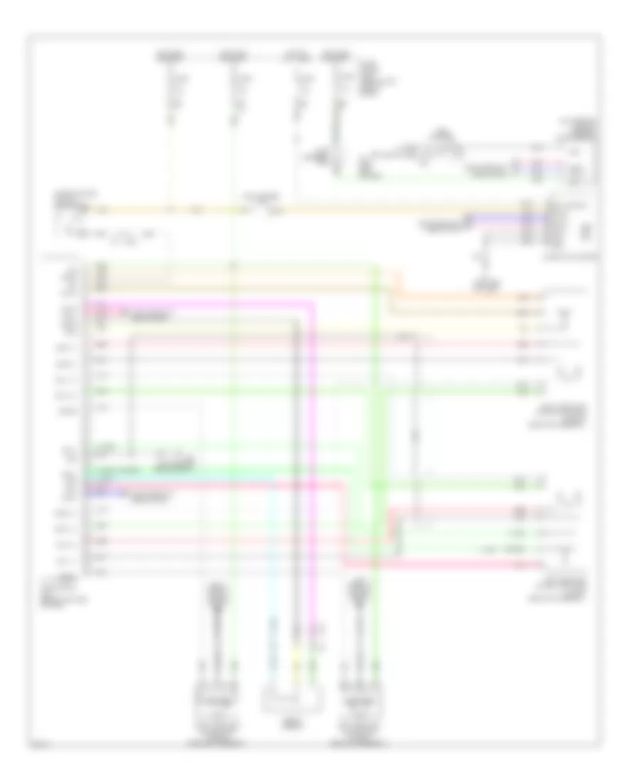
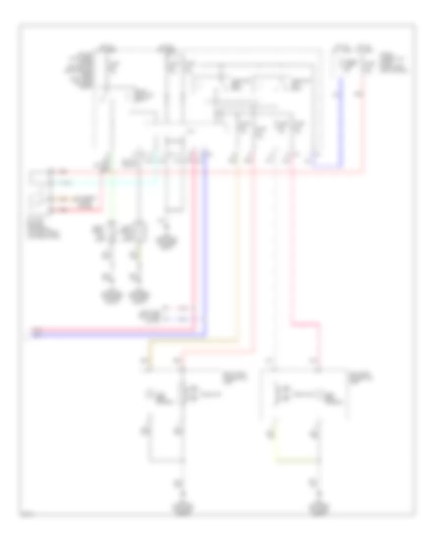
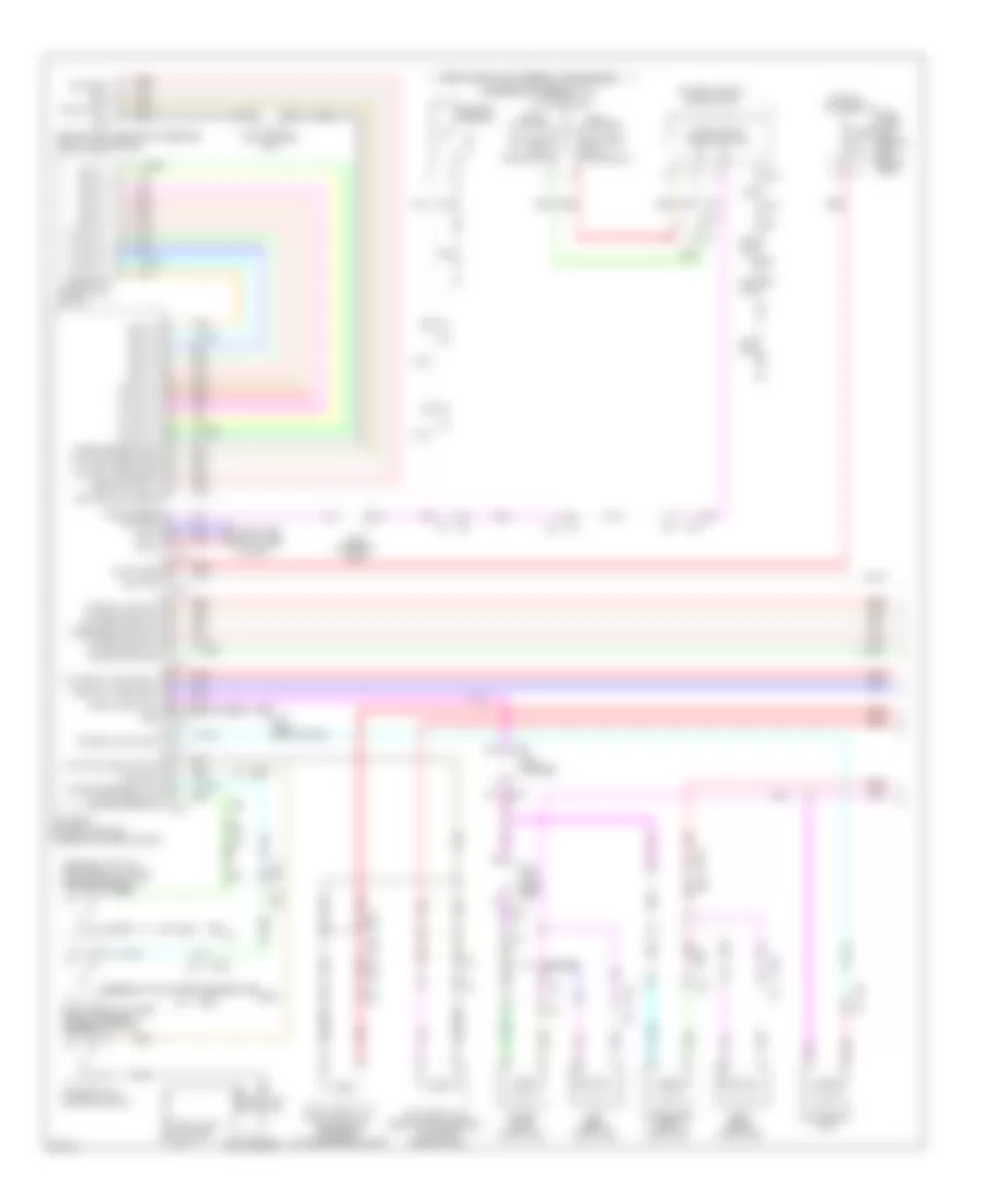
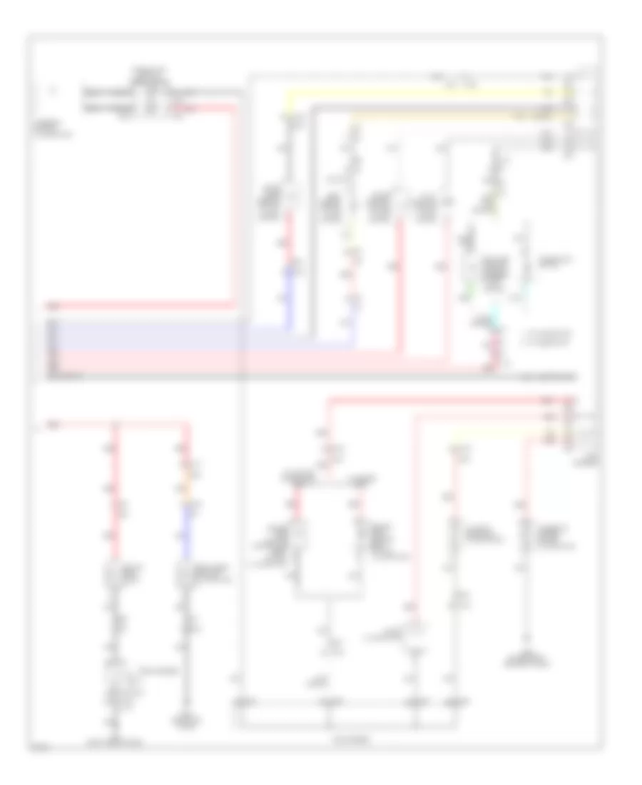
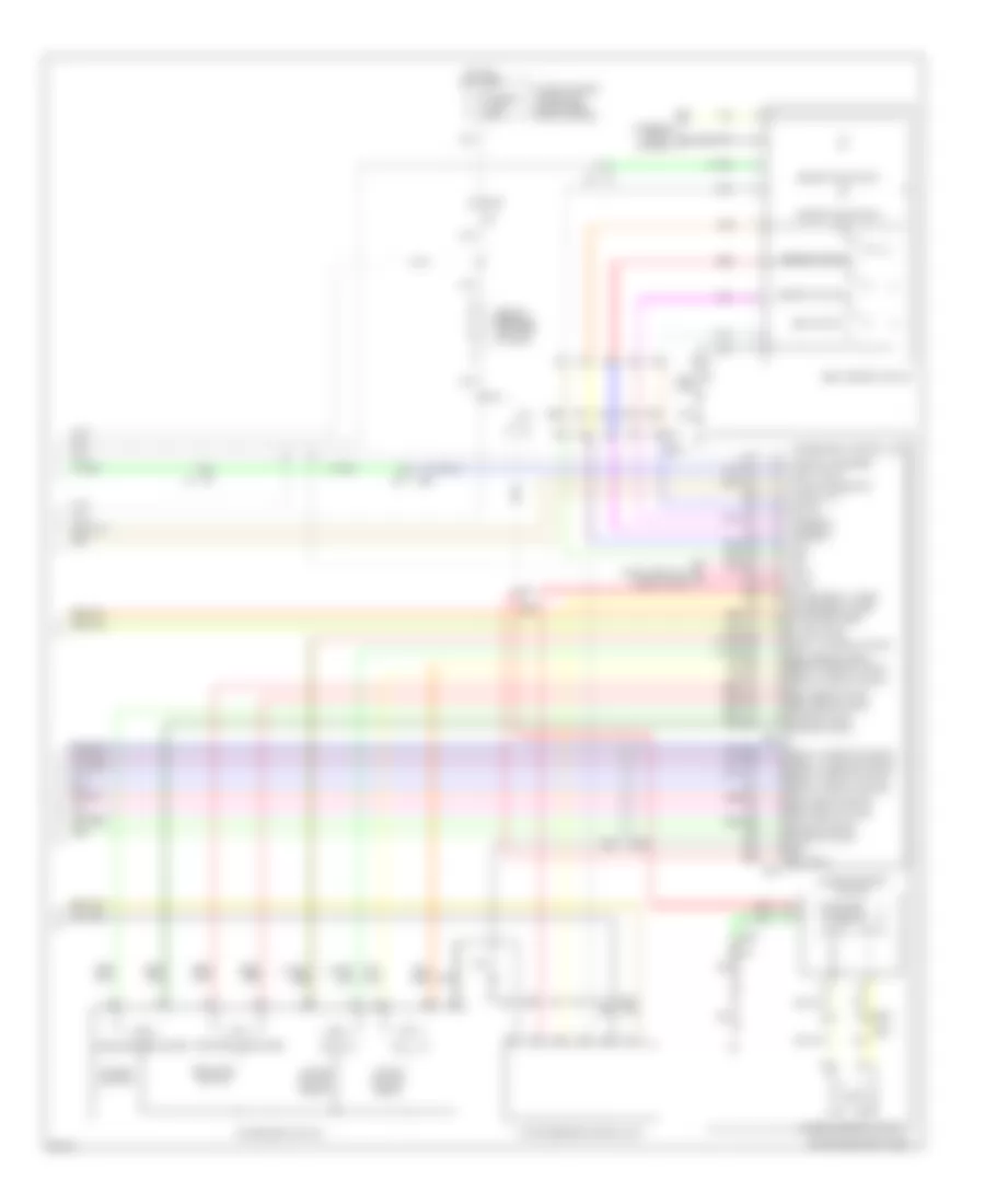
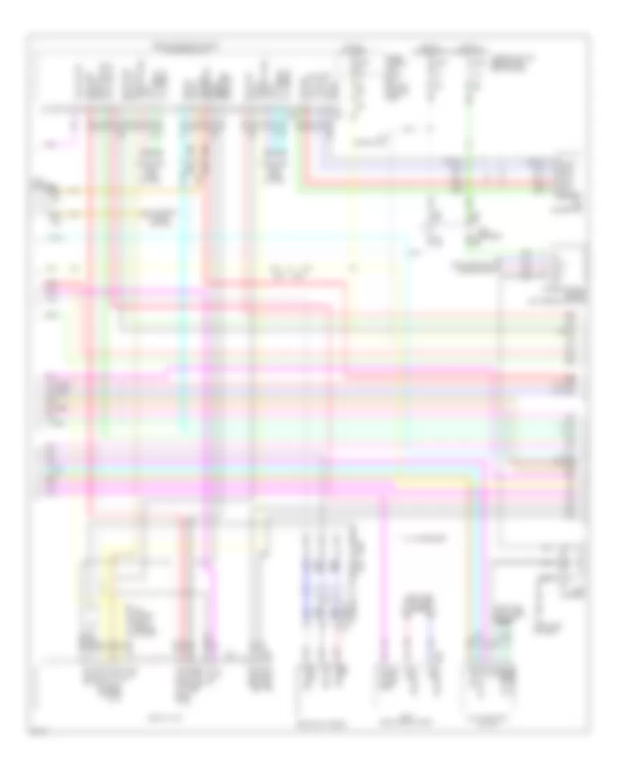
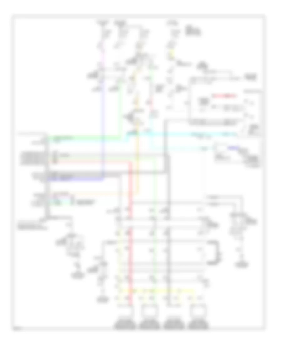
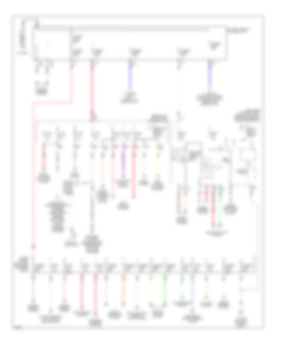
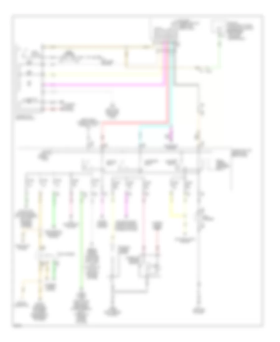
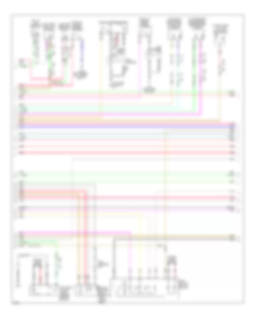
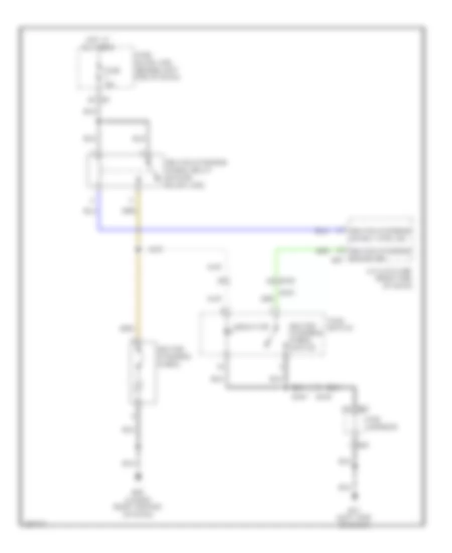
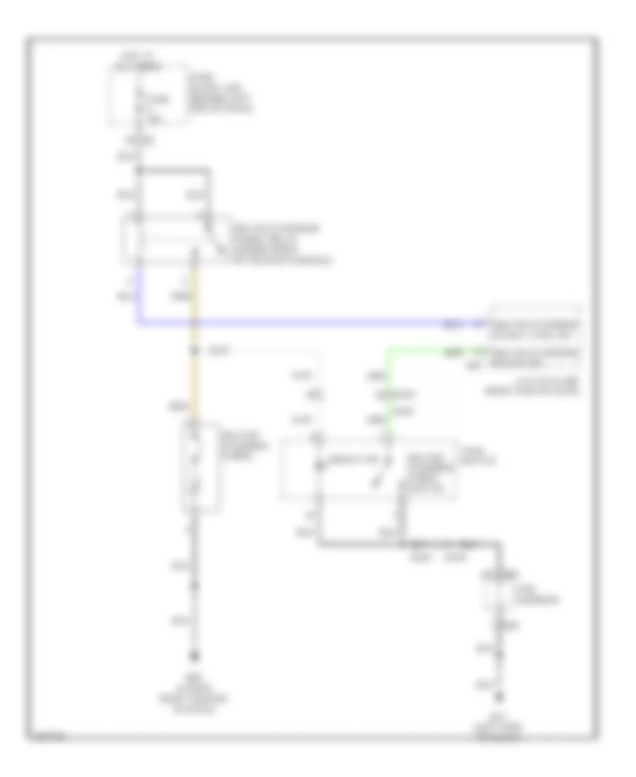
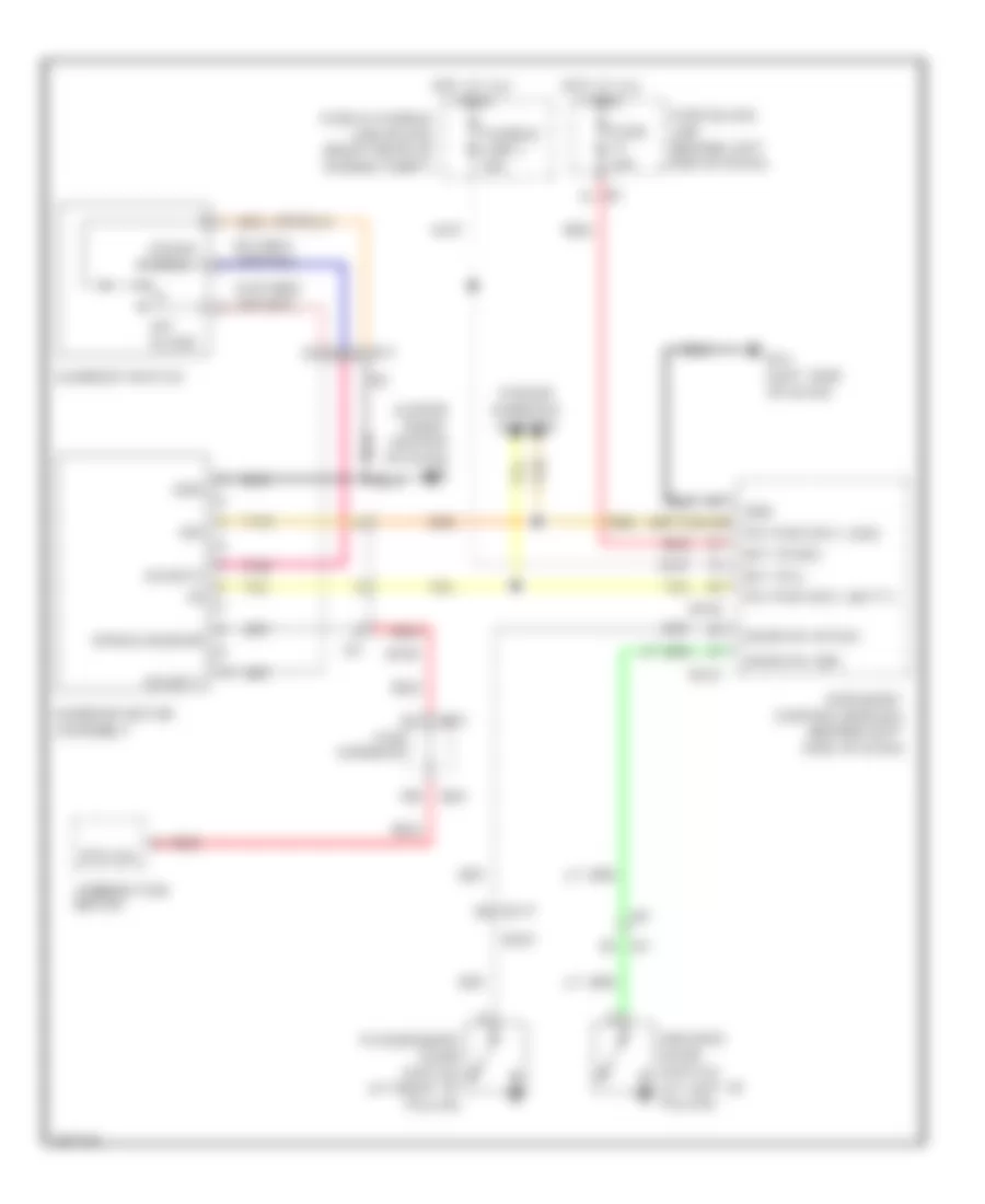
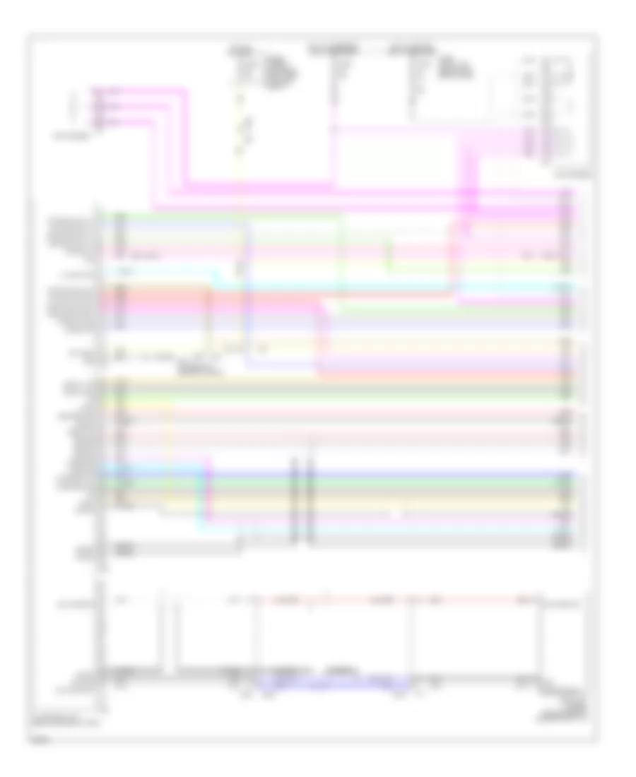
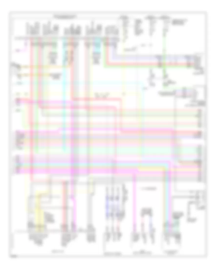
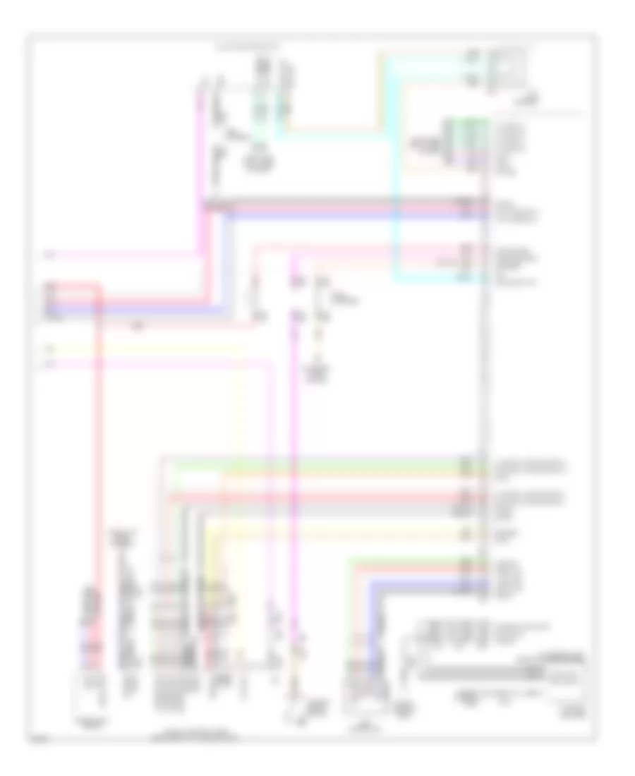
3.5L Hybrid, Automatic A/C Wiring Diagram (2 of 4) for Infiniti Q70 5.6 2014
List of elements for 3.5L Hybrid, Automatic A/C Wiring Diagram (2 of 4) for Infiniti Q70 5.6 2014:
- (right front of engine compt) heater pump
- (right side of dash) m95
- Aroma motor (w/ forest air) (lower left rear of blower unit)
- Blower motor (bottom of blower unit)
- Ctrl
- Drive mode select switch
- E106
- E46 (right side of engine compt)
- Eco
- F/b
- Fan f/b
- Fanout
- Gnd
- Ign
- Intake door motor (left side of blower unit)
- Intake sensor (left side of hvac unit)
- Interior lights system
- M135
- M201
- M26
- M28
- M30
- M95 (right side of dash)
- Pcb harness
- Pnk
- Power transistor (bottom of blower unit)
- Red
- Right mode door motor (right side of hvac unit)
- Sig
- Snow
- Sport
- Standard
- Upper ventilator door motor
- W/ forest air
- W/o forest air
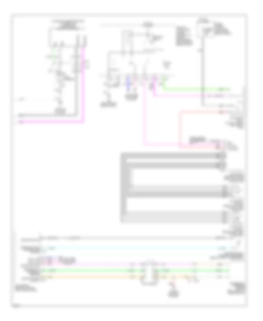
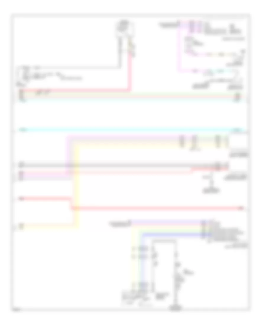
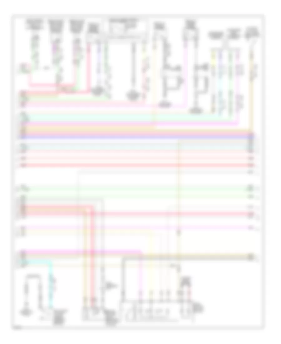
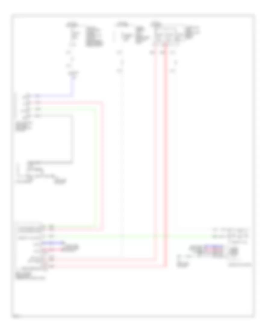
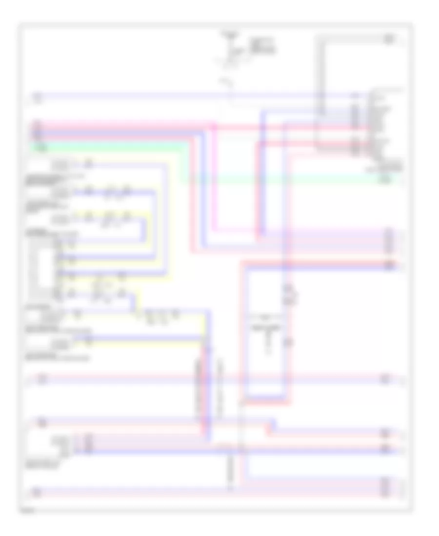
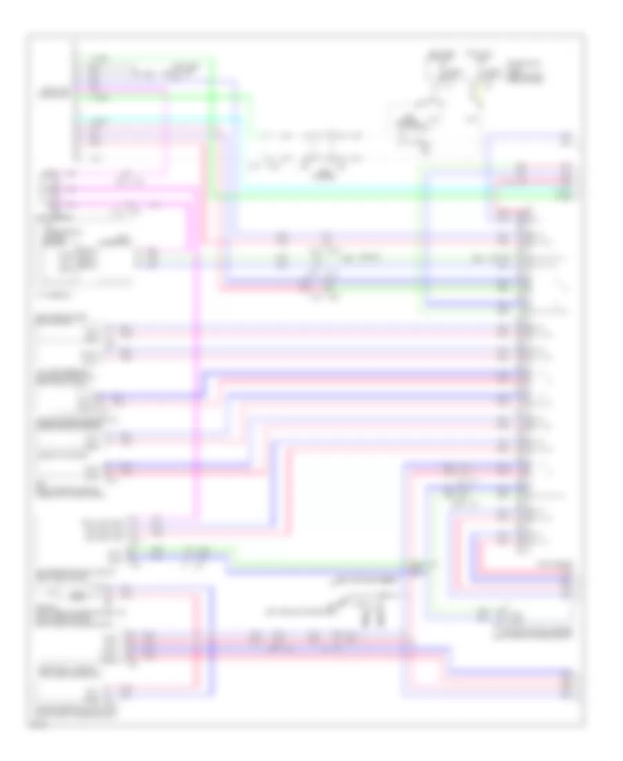
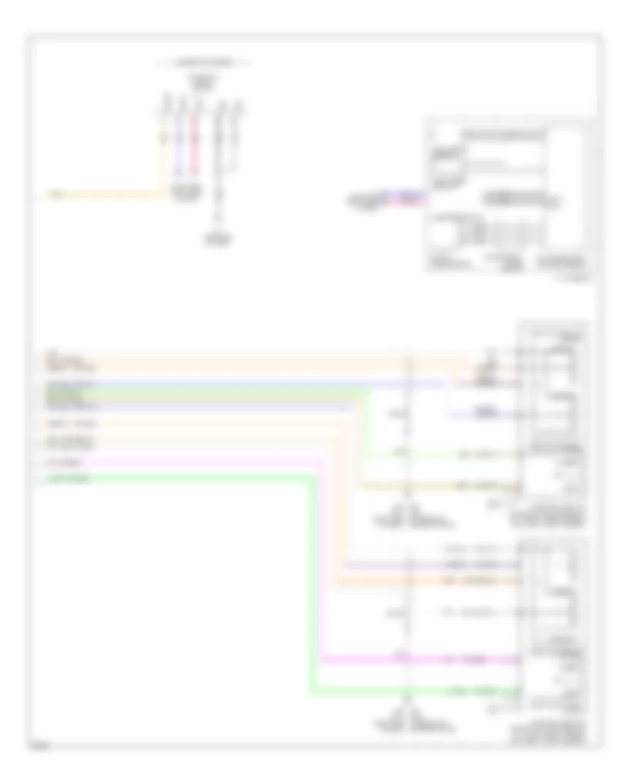
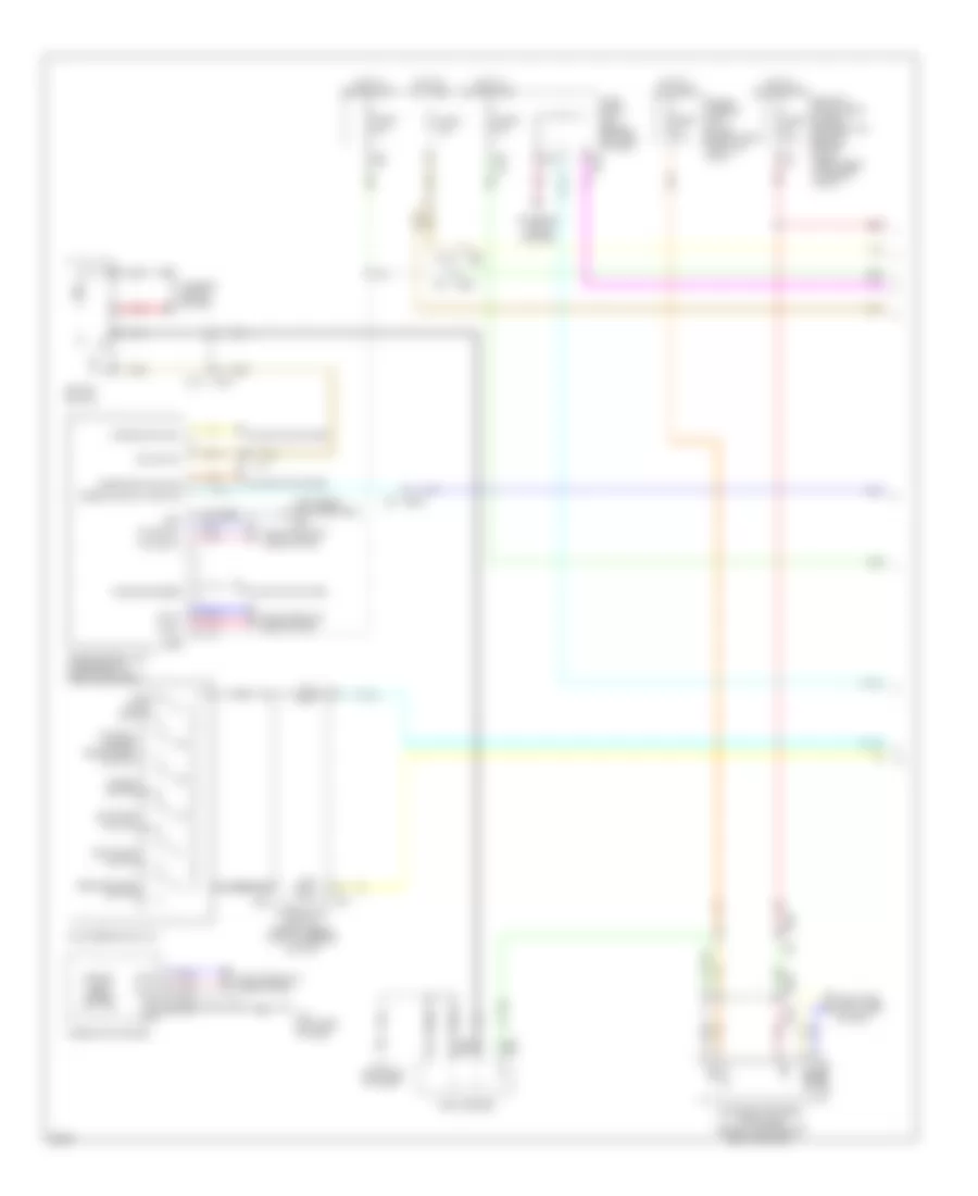
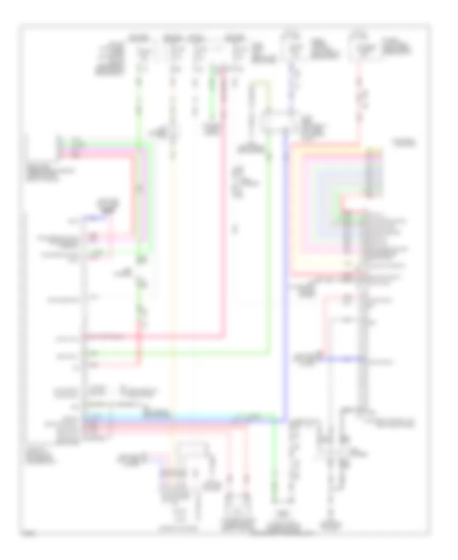
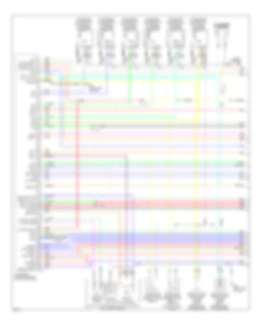
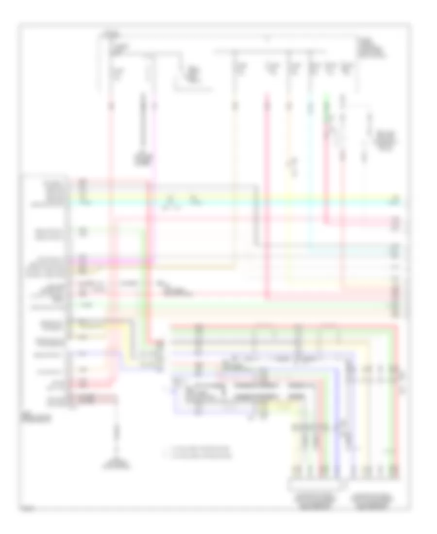
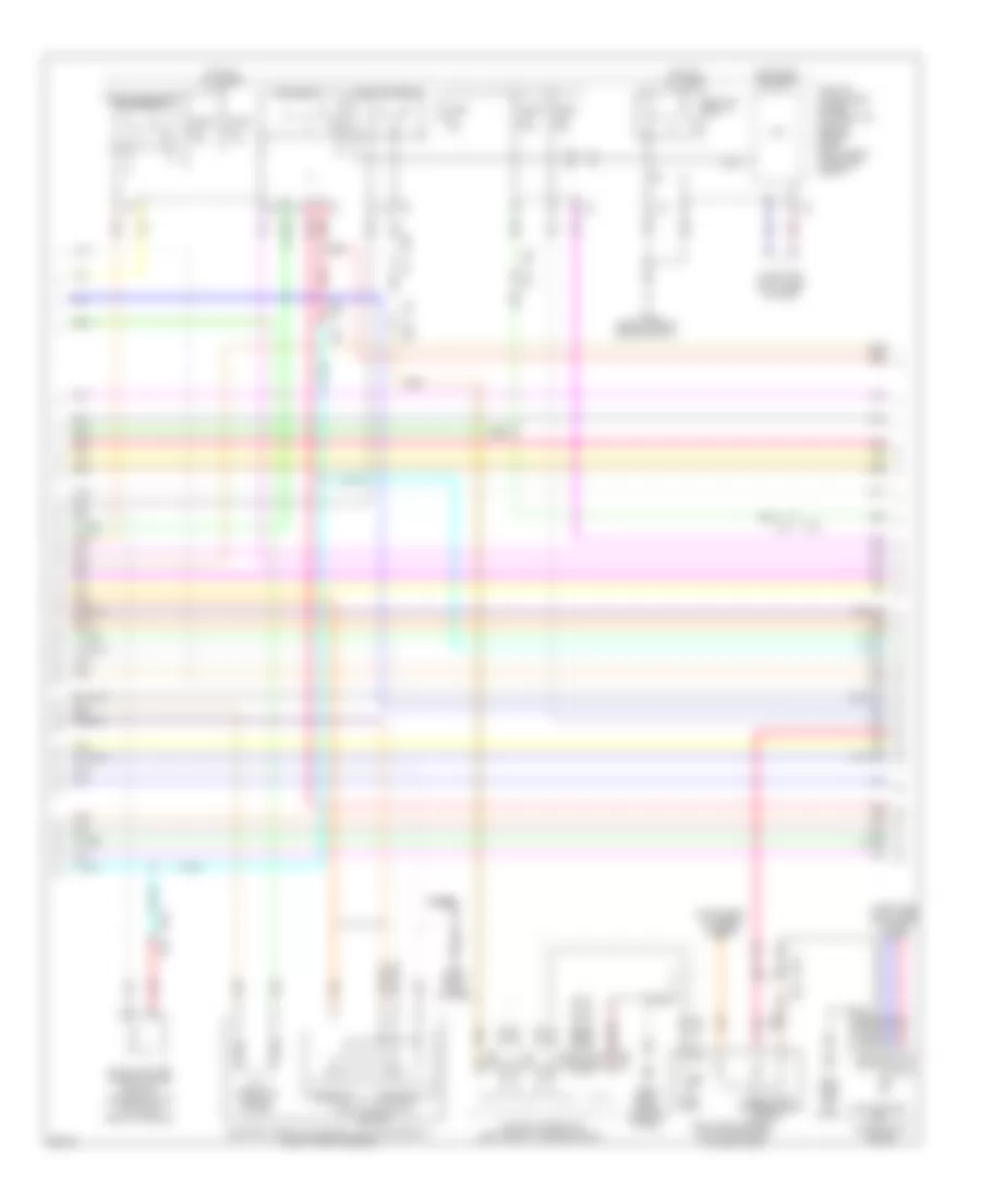
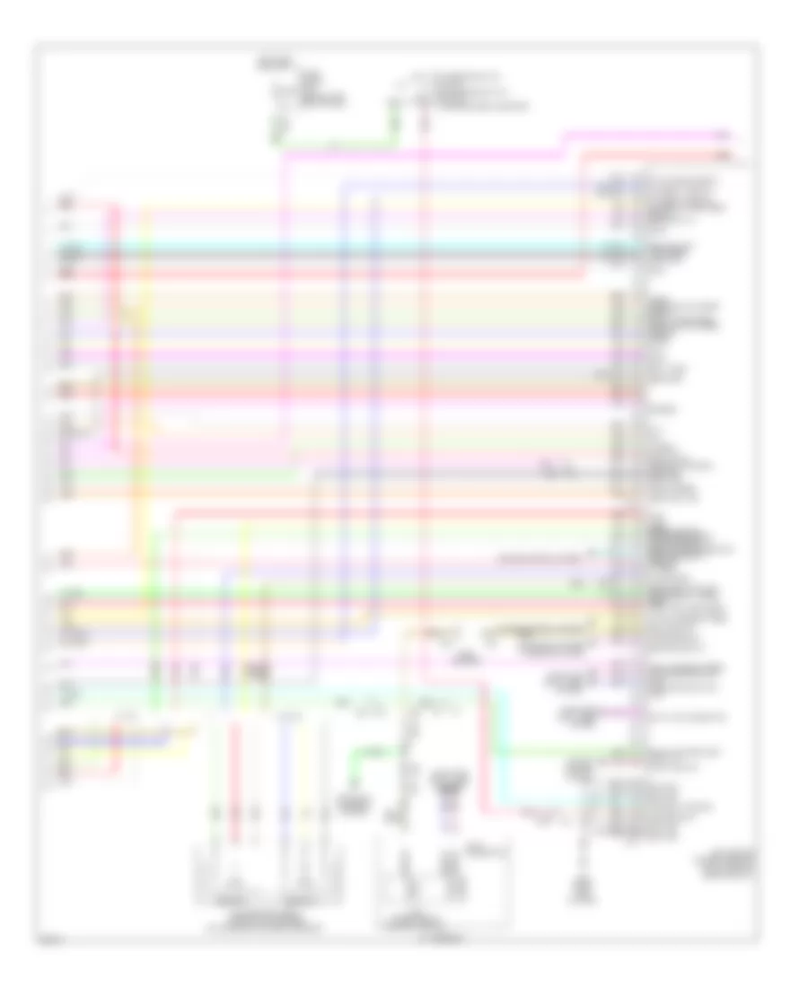
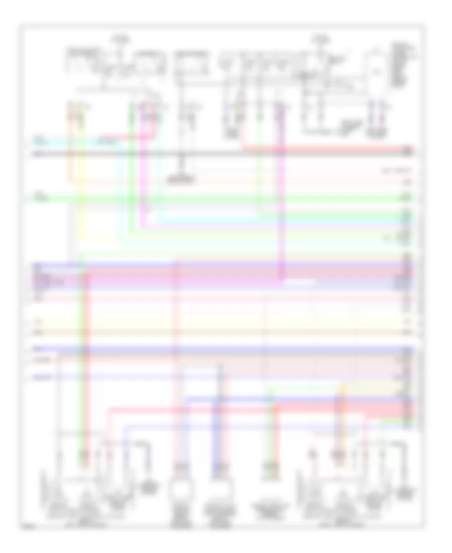
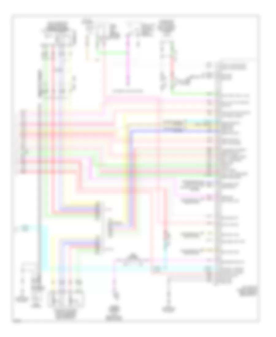
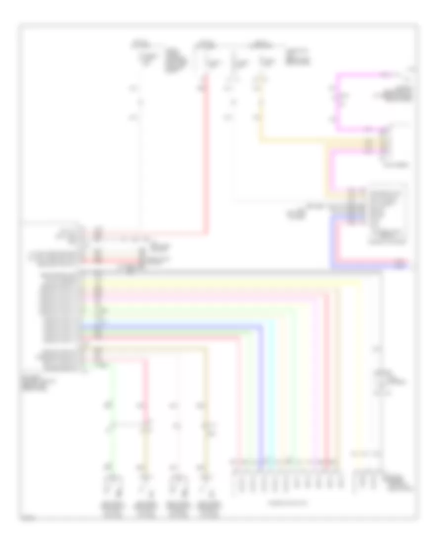
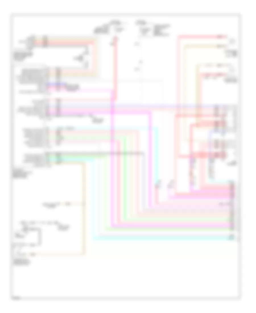
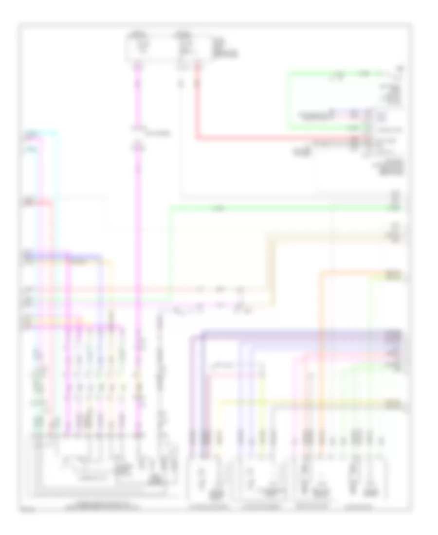
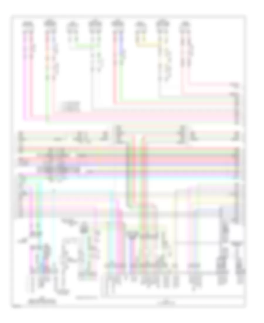
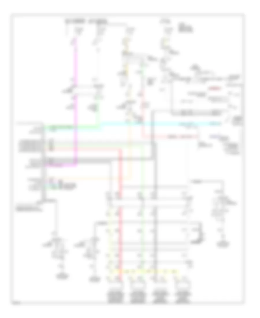
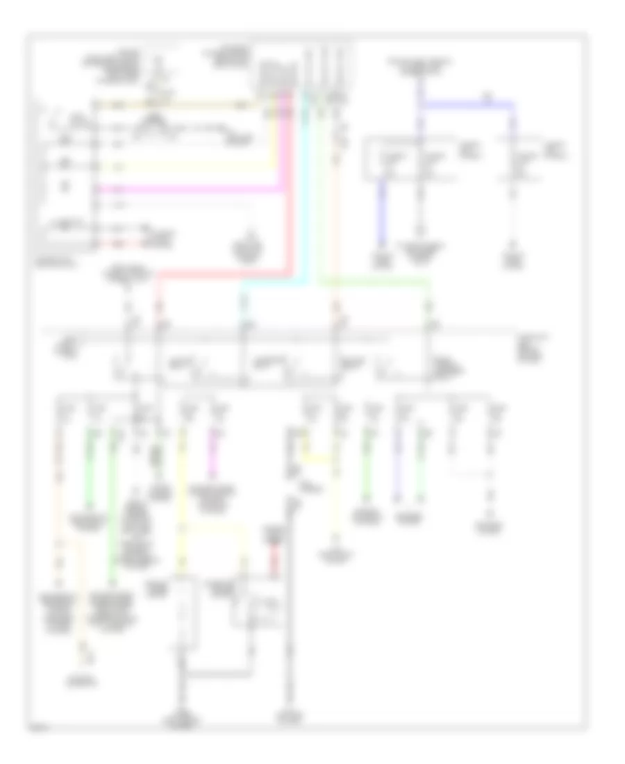
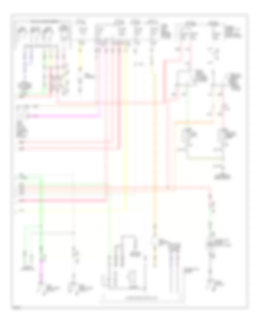
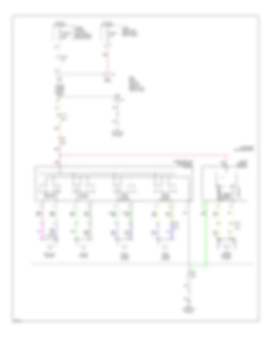
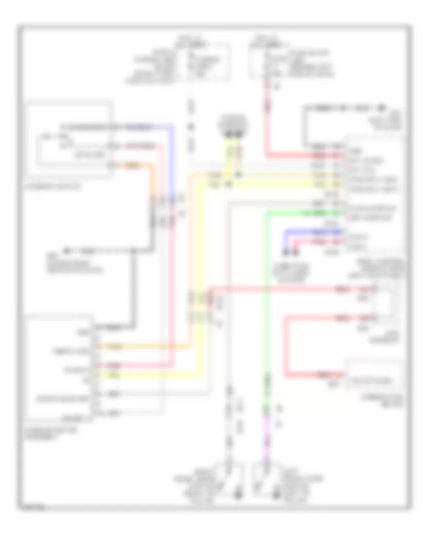
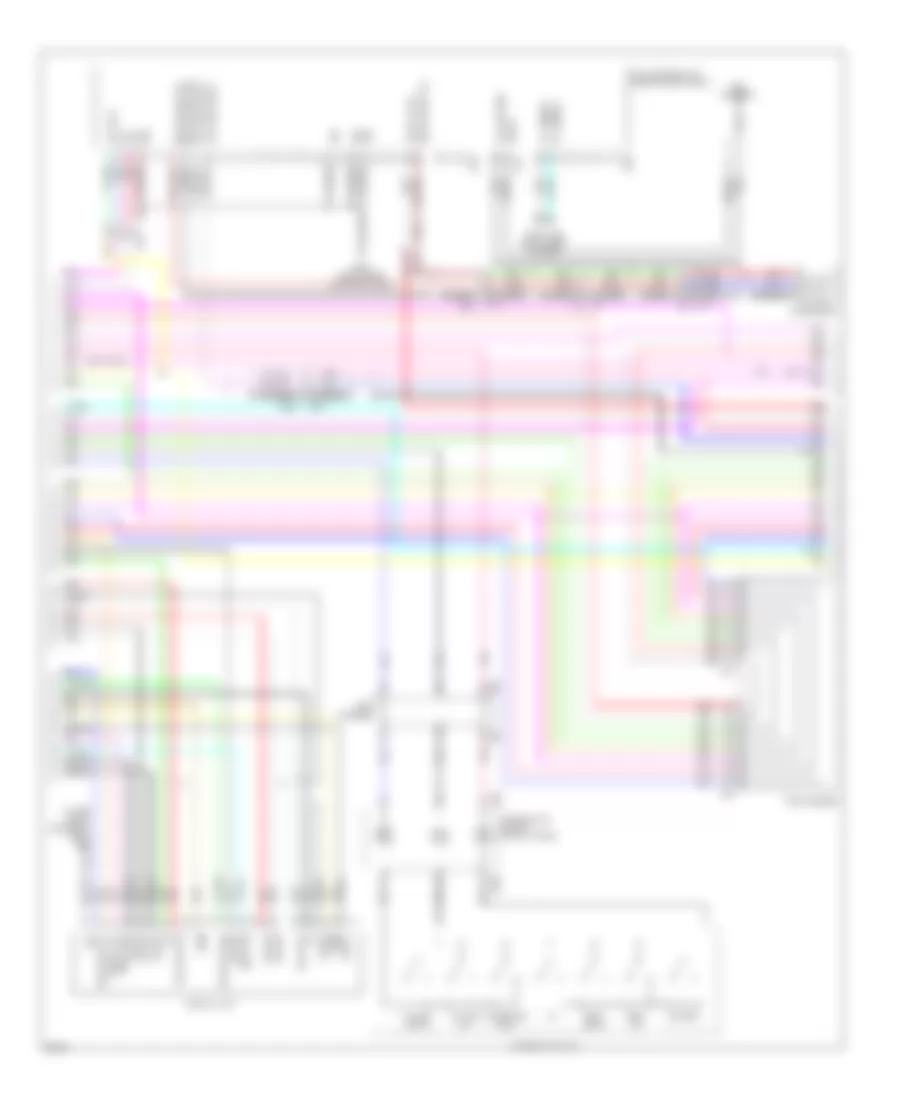
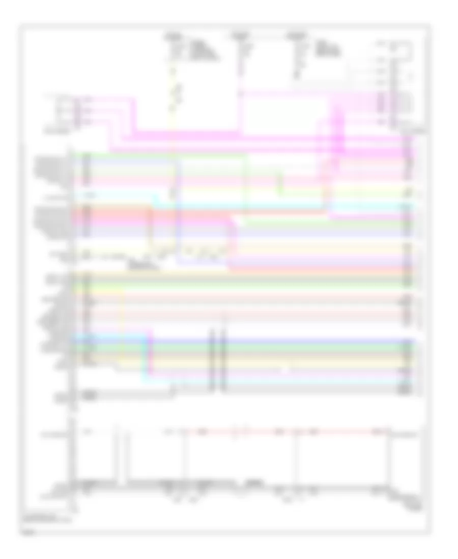
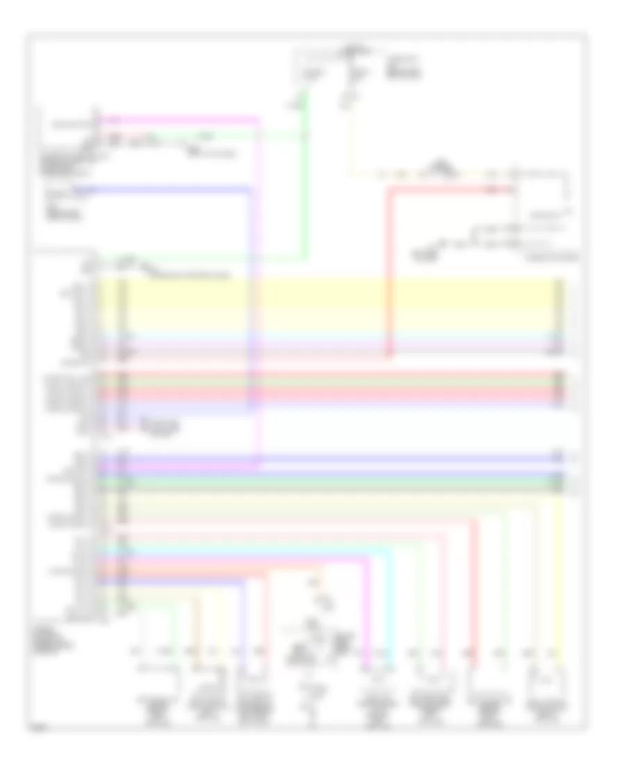
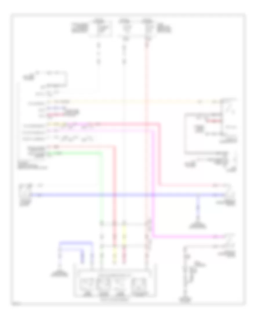
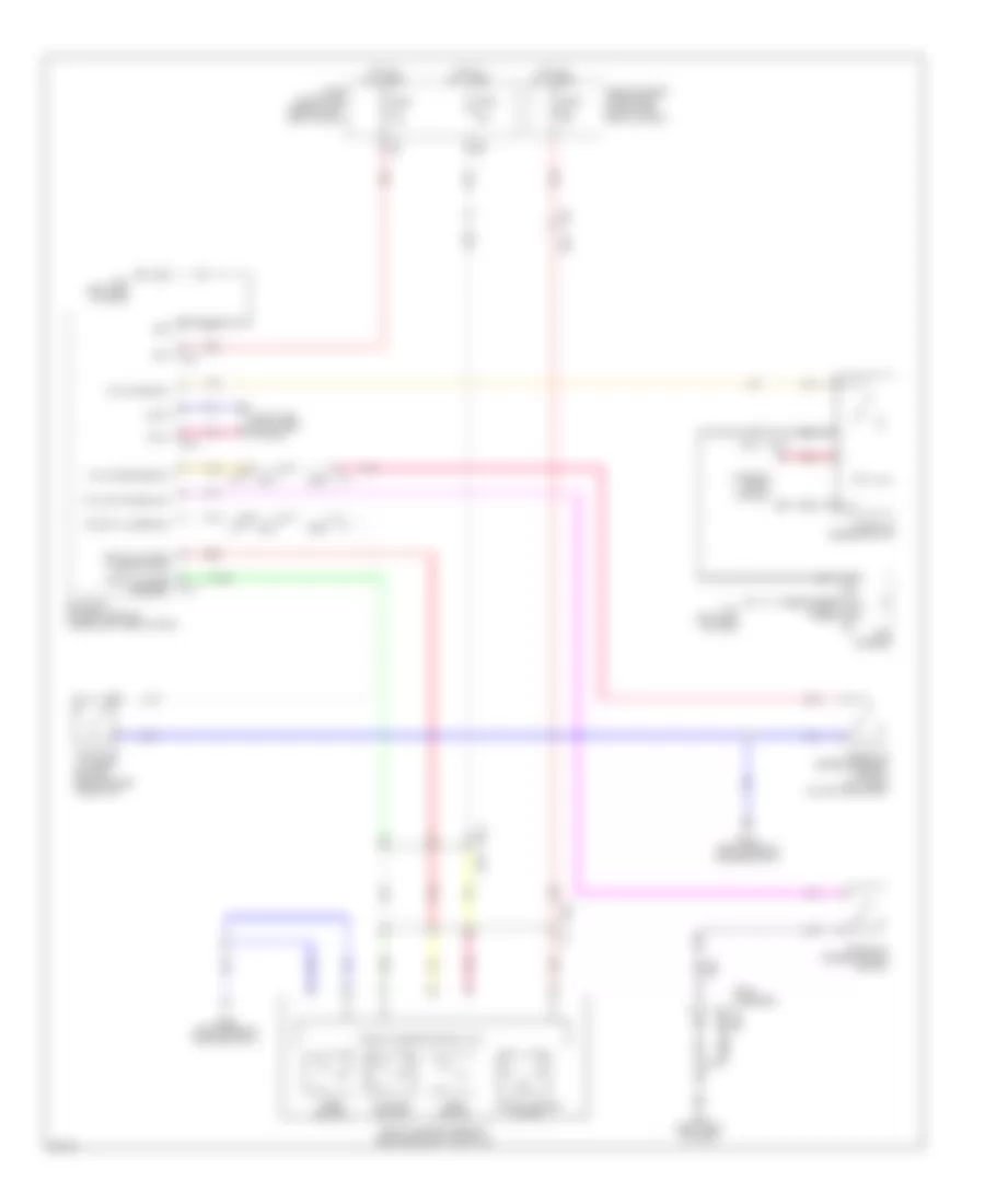
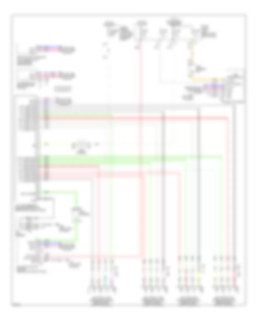
3.5L Hybrid, Automatic A/C Wiring Diagram (3 of 4) for Infiniti Q70 5.6 2014
List of elements for 3.5L Hybrid, Automatic A/C Wiring Diagram (3 of 4) for Infiniti Q70 5.6 2014:
- (left rear of engine compt) e22
- (left side of engine) electric compressor
- A/c auto amp (right end of dash)
- Air mix door motor (dr) cool drv sig
- Air mix door motor (dr) hot drv sig
- Air mix door motor (dr) pbr f/b sig
- Air mix door motor (pass) cool drv sig
- Air mix door motor (pass) hot drv sig
- Air mix door motor (pass) pbr f/b sig
- Aqs power
- Aqs s gnd
- Aqs s output
- Aroma motor (fragrant wood) drv sig
- Aroma motor (leaf scent) drv sig
- Aroma motor pbr f/b sig
- E106 m6
- Each door motor pbr pwr sply
- Exhaust gas/ outside odor detecting sensor (w/ forest air) (front of engine compt)
- F103
- Gnd
- Ign
- Intake door motor fre drv sig
- Intake door motor pbr f/b sig
- Intake door motor rec drv sig
- Intake sens gnd/each door motor pbr gnd
- Intake sens sig
- Ion on/off
- Ionizer (w/ forest air) (on driver's hvac duct)
- Left air mix door motor (left side of hvac unit)
- Left mode door motor (left side of hvac unit)
- M11 (left side of dash)
- M20
- M23
- M28
- M30
- M304
- M95 (right side of dash)
- Mode door motor (dr) def drv sig
- Mode door motor (dr) pbr f/b sig
- Mode door motor (dr) vent drv sig
- Mode door motor (pass) def drv sig
- Mode door motor (pass) pbr f/b sig
- Mode door motor (pass) vent drv sig
- Pcb harness
- Pnk
- Rear mode door motor (lower left side of hvac unit)
- Red
- Right air mix door motor (right side of hvac unit)
- Rr mode door motor foot drv sig
- Rr mode door motor pbr f/b sig
- Rr mode door motor vent drv sig
- Up vent door motor (dr) cls drv sig
- Up vent door motor open drv sig
- Up vent door motor pbr f/b sig
- W/ forest air
- W/o forest air
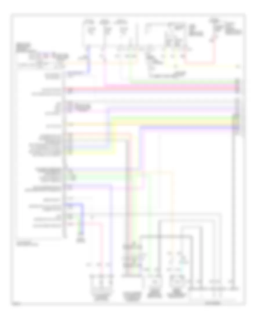
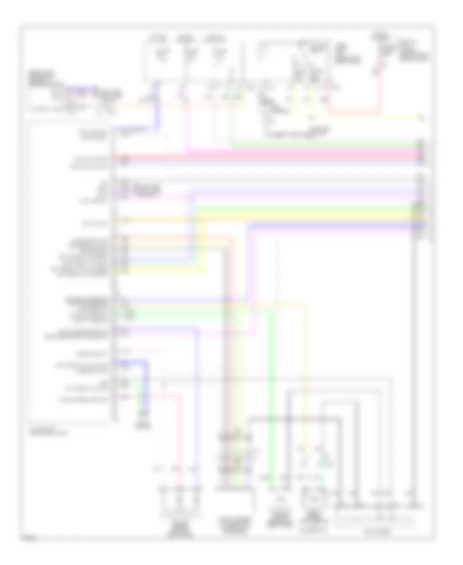
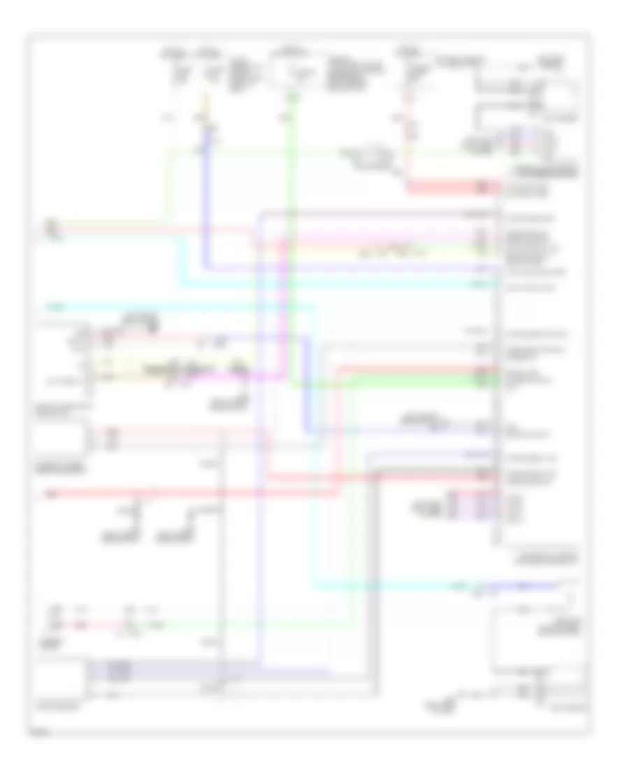
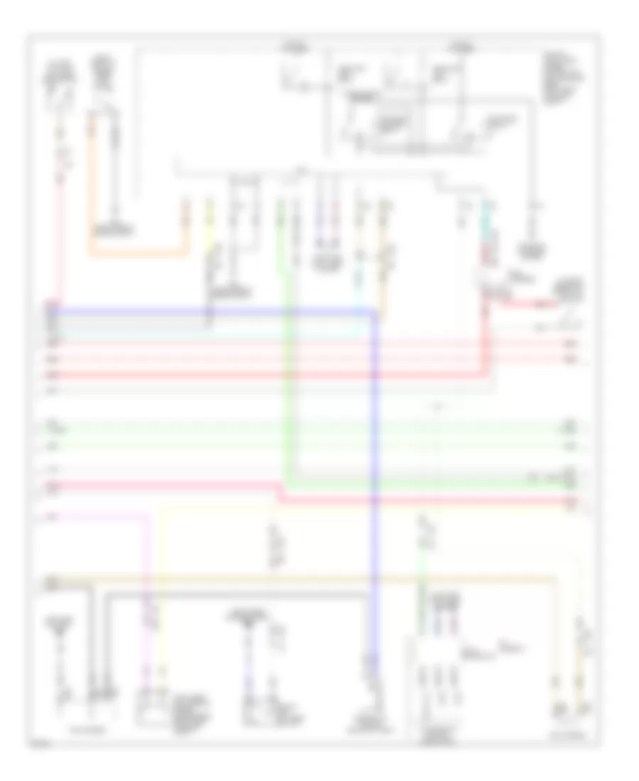
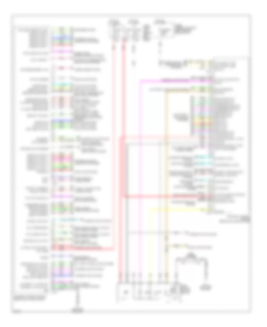
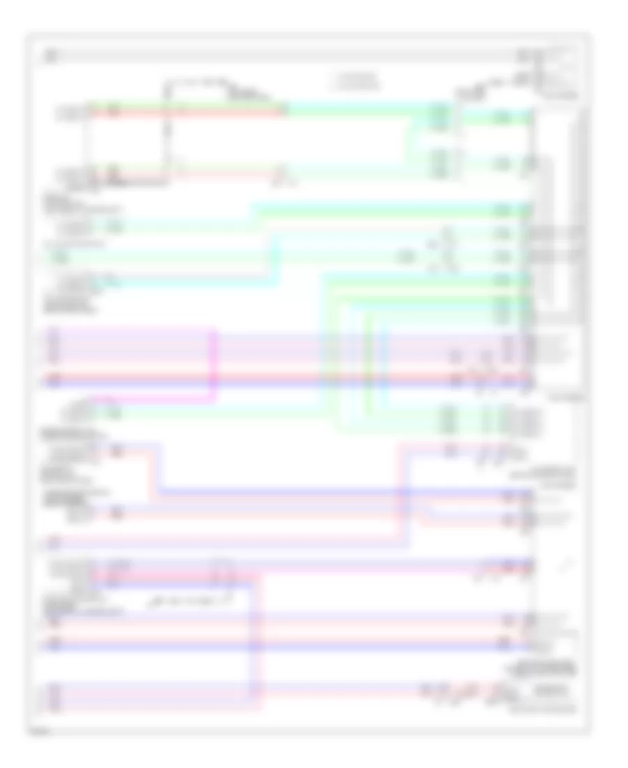
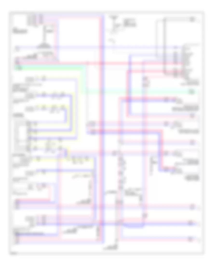
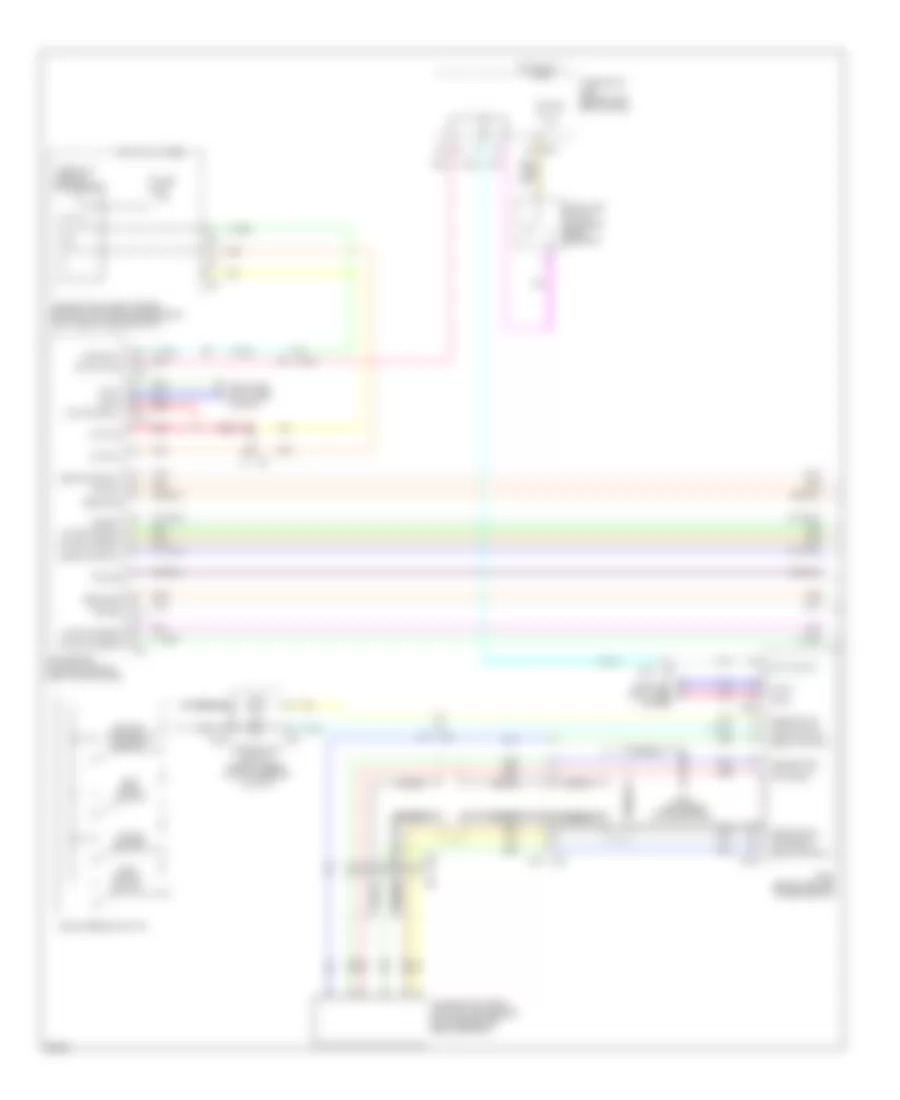
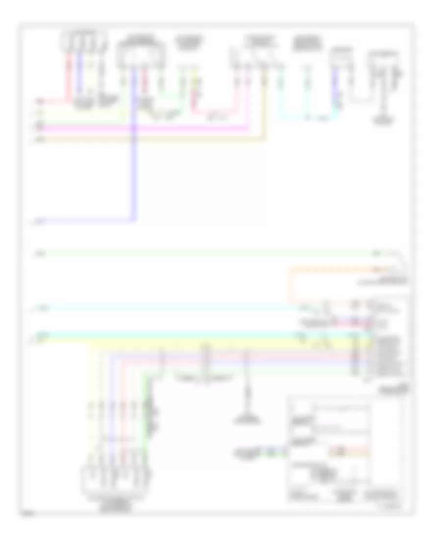
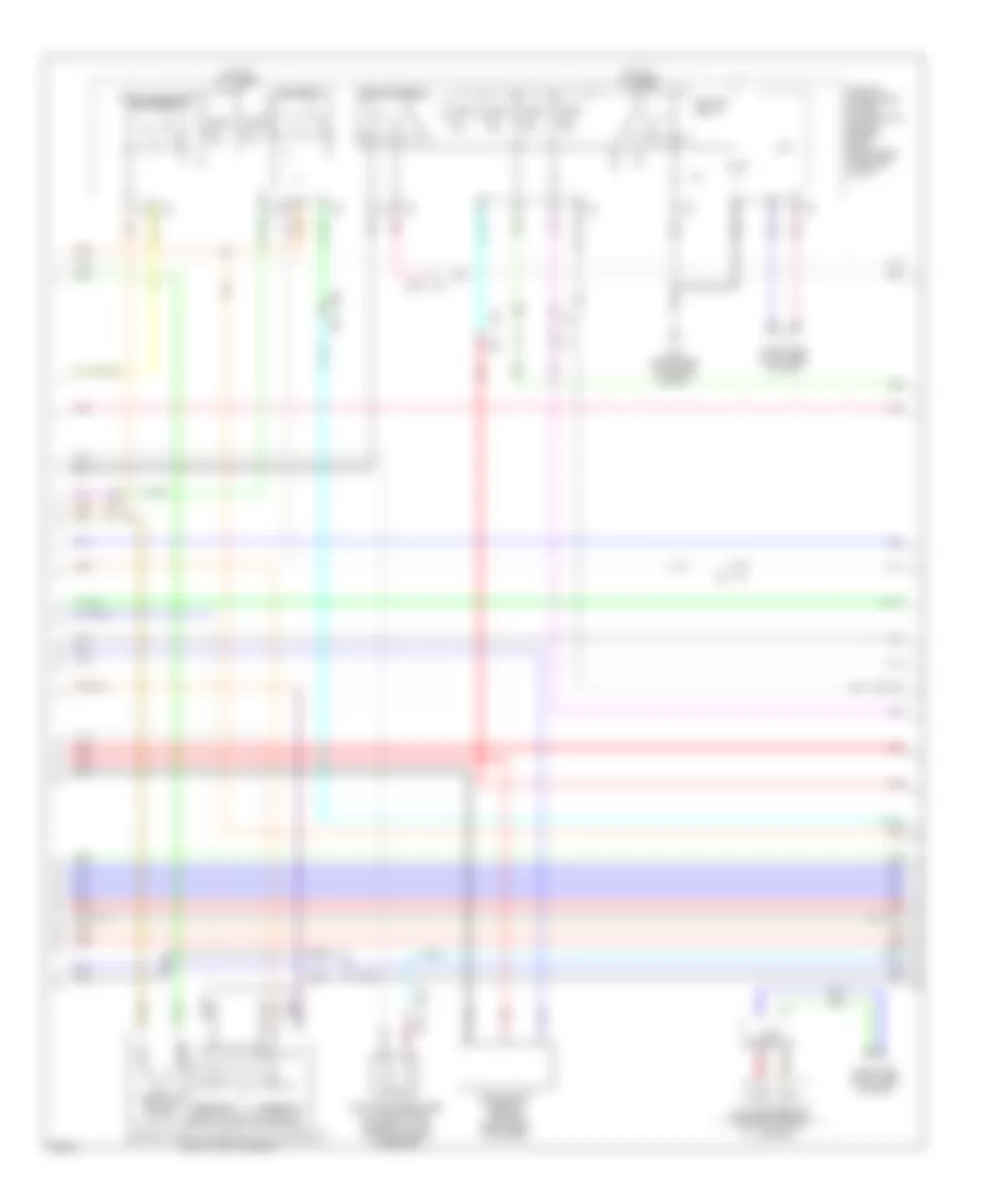
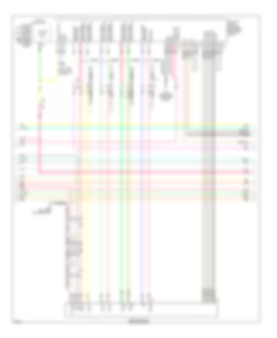
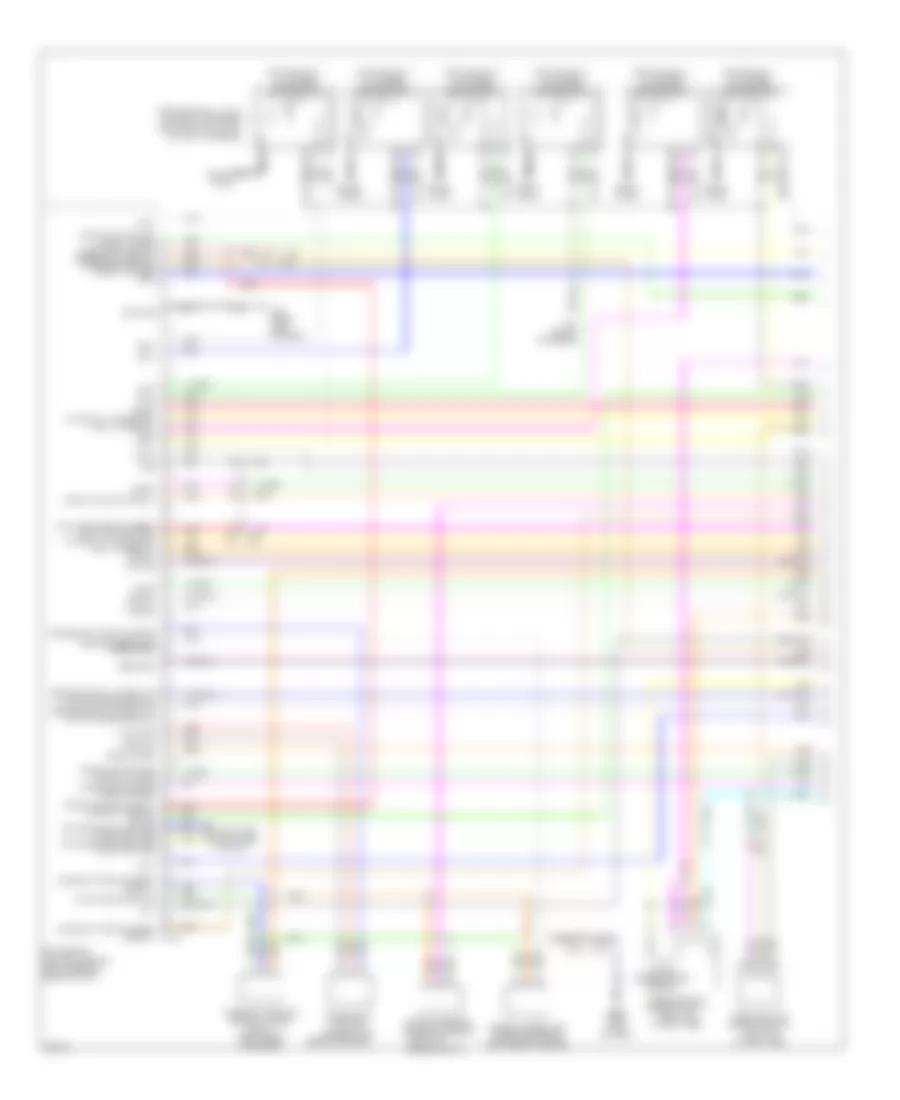
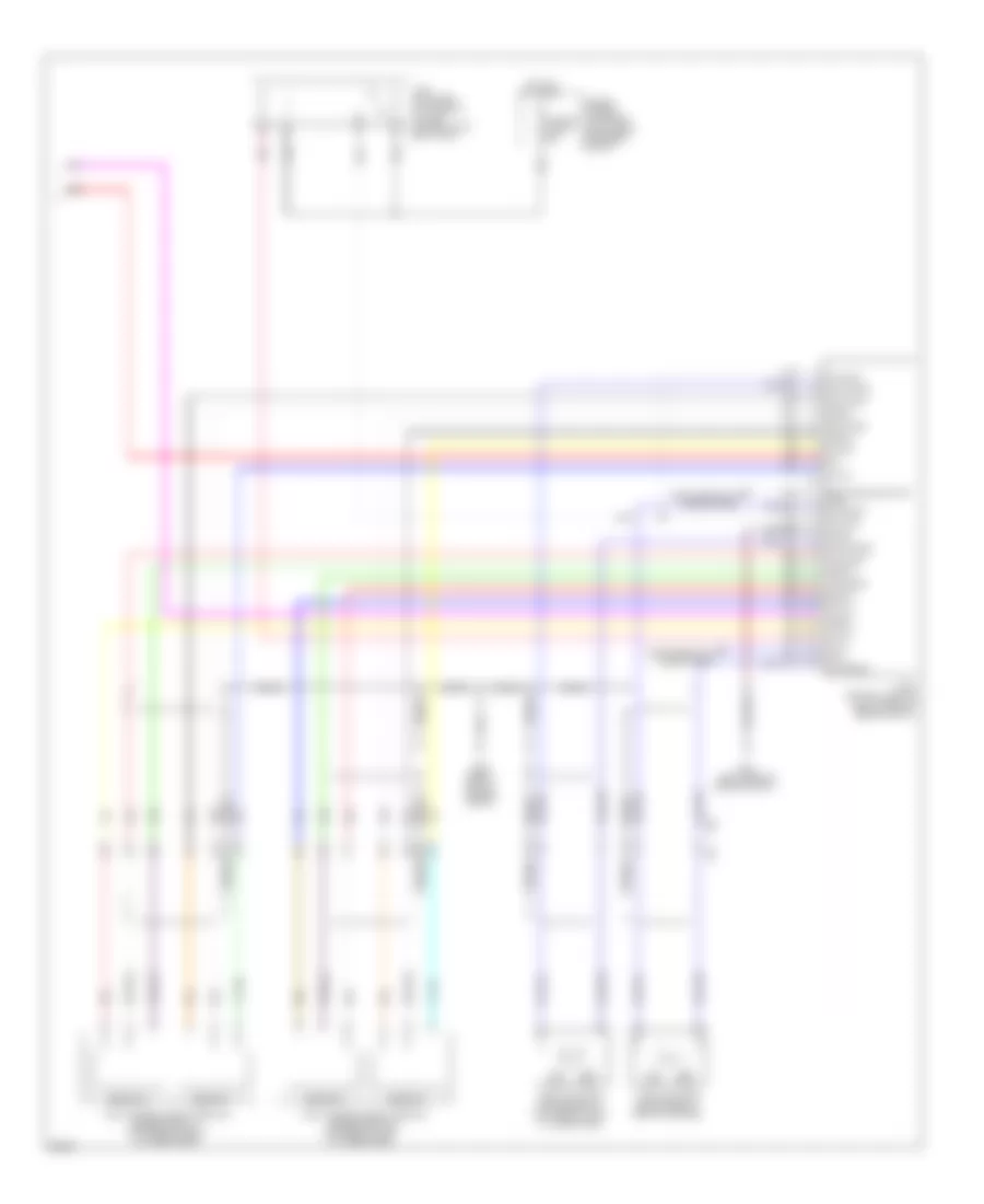
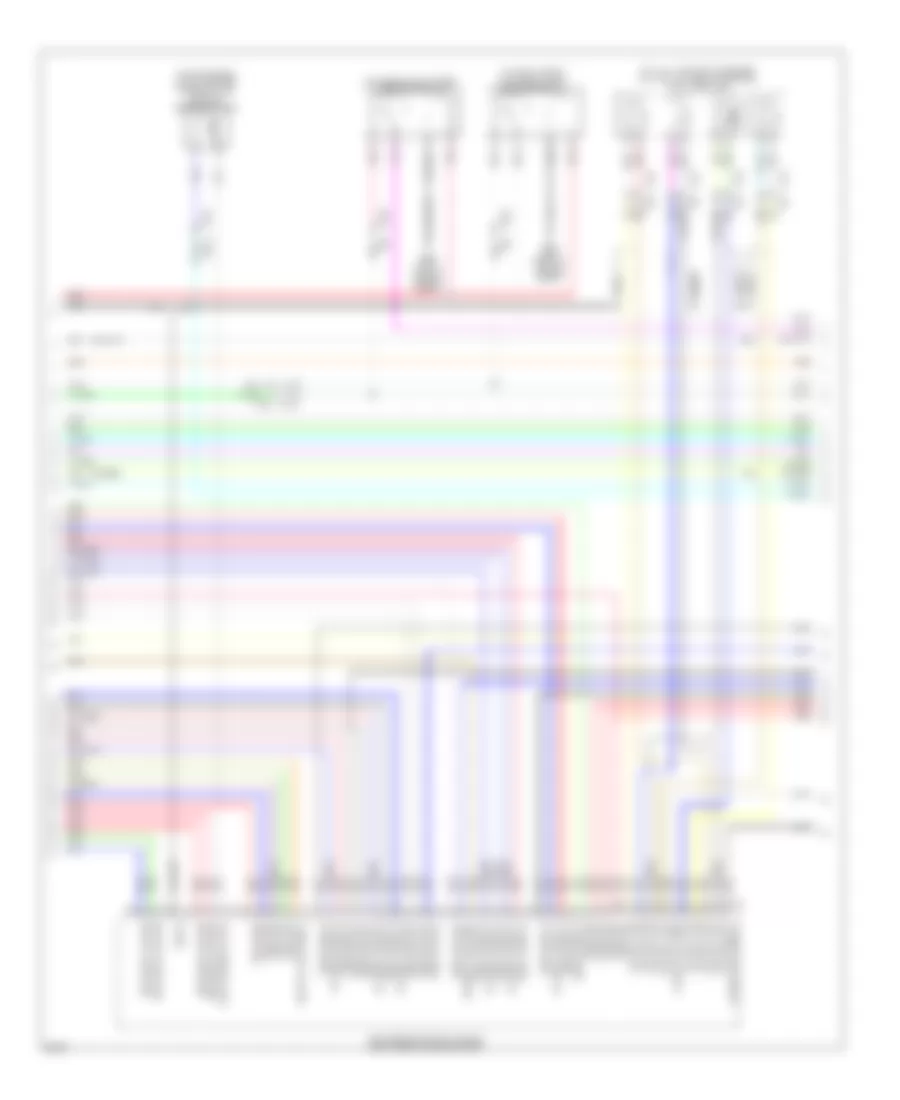
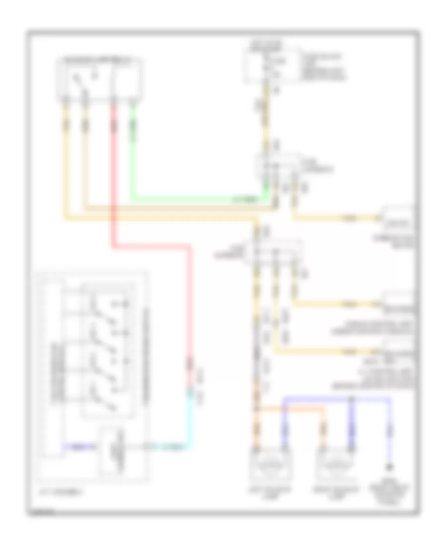
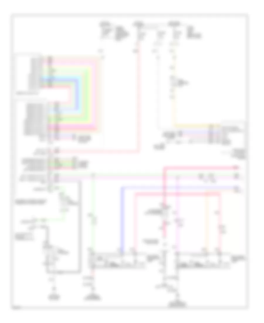
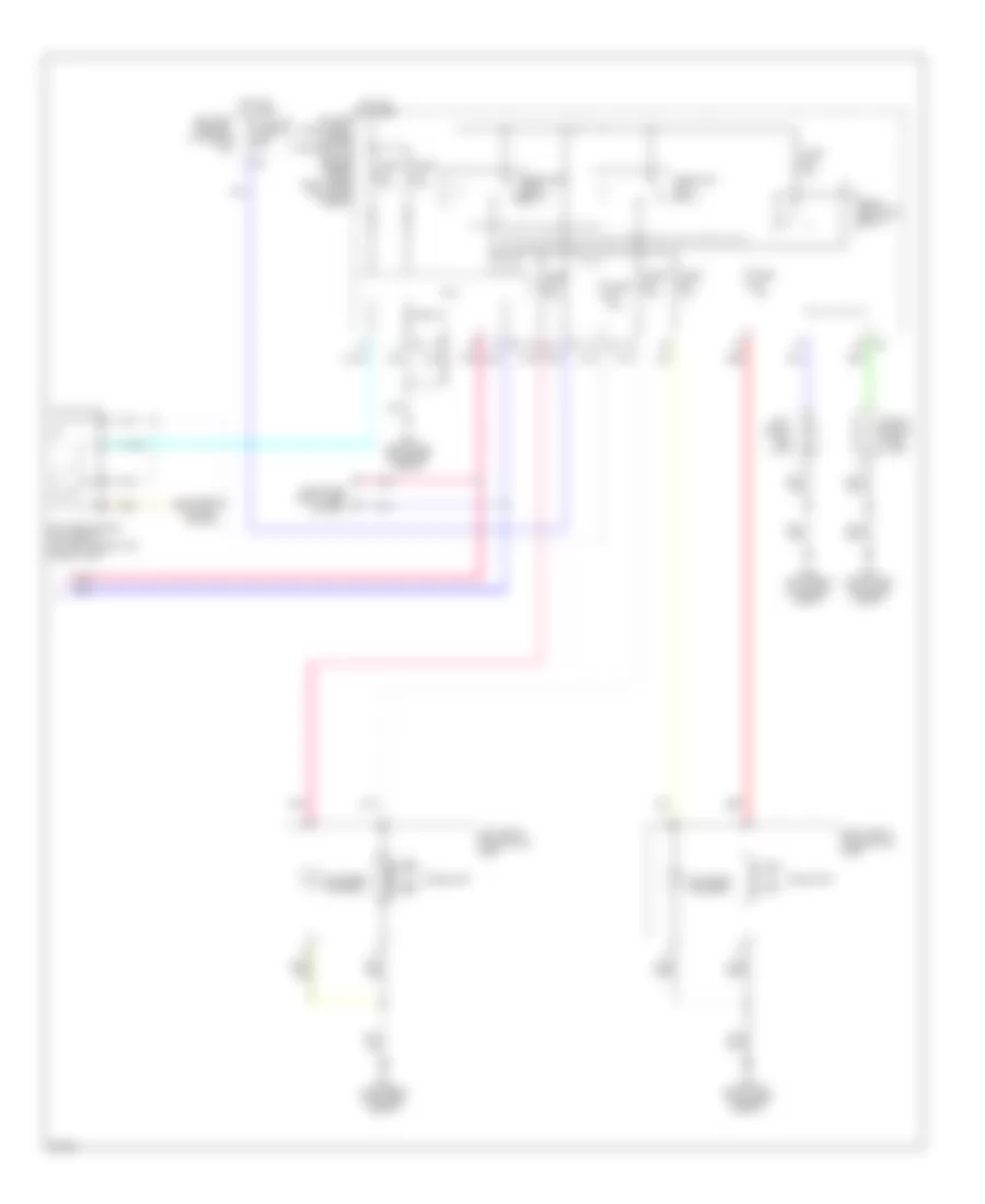
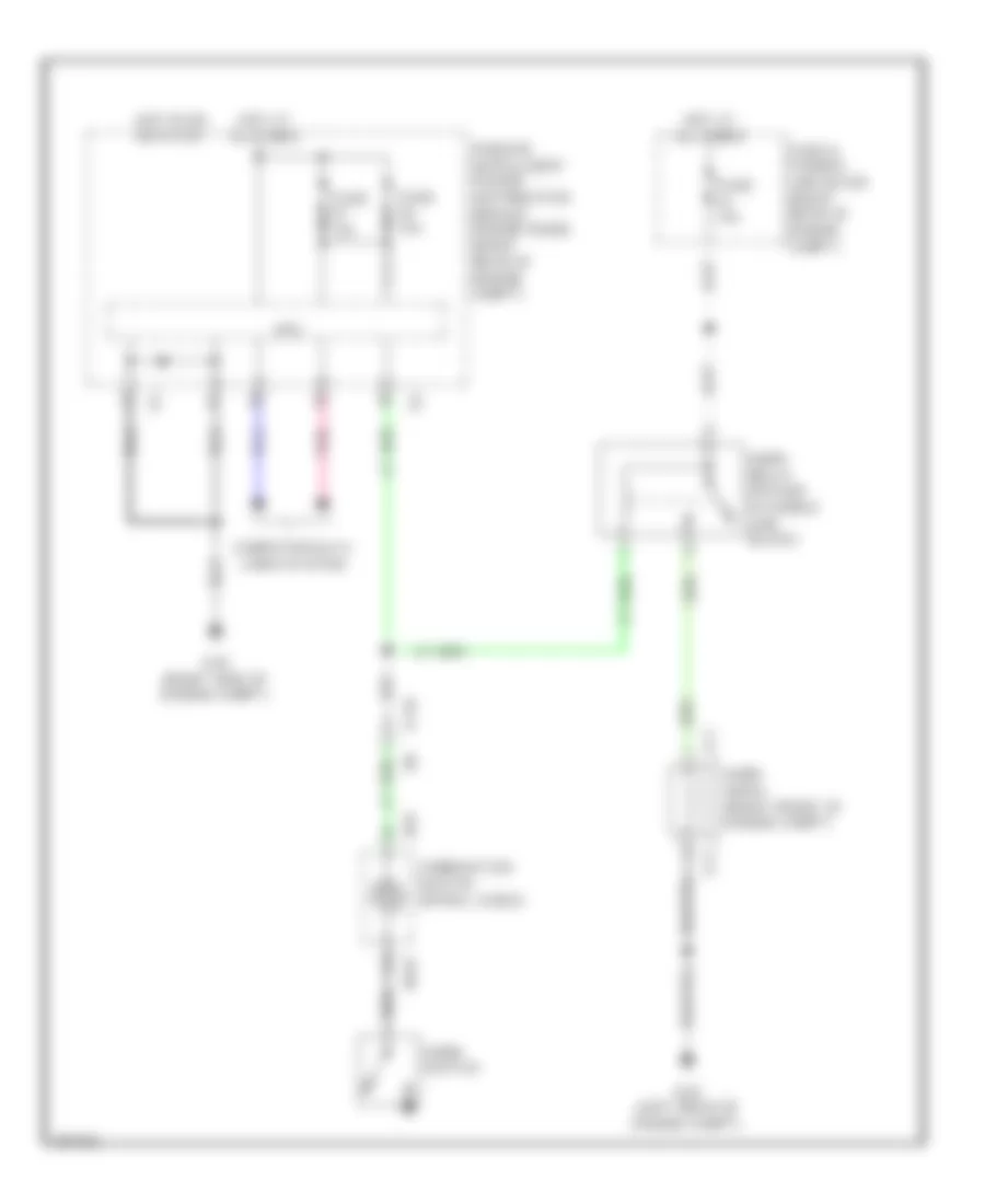
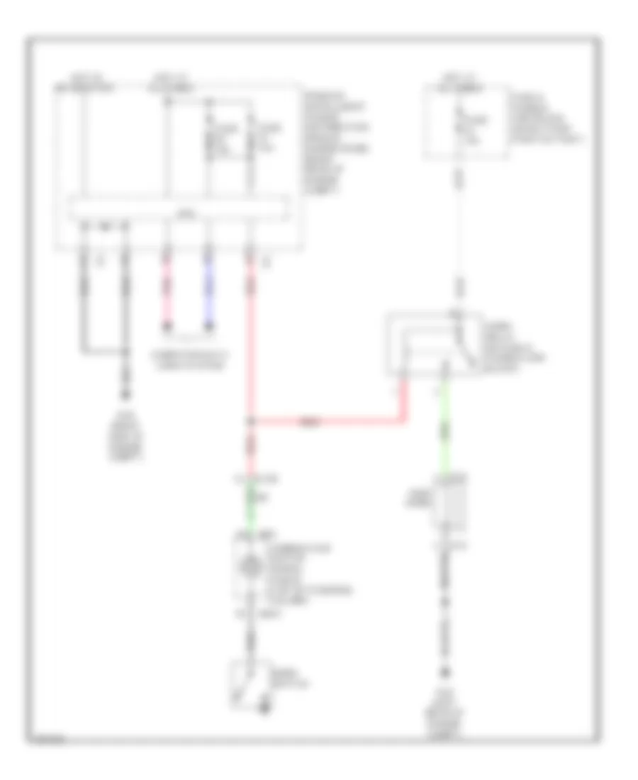
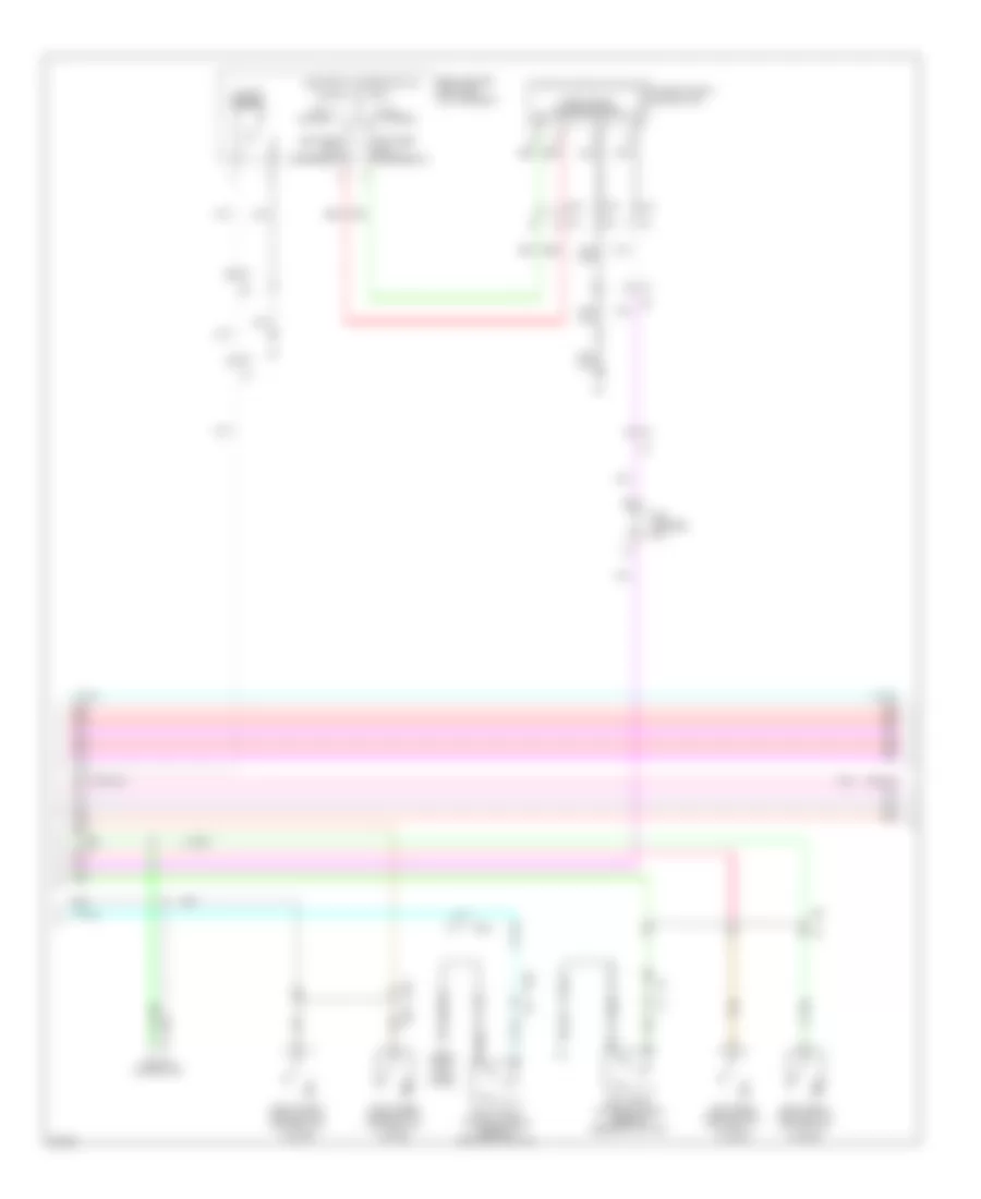
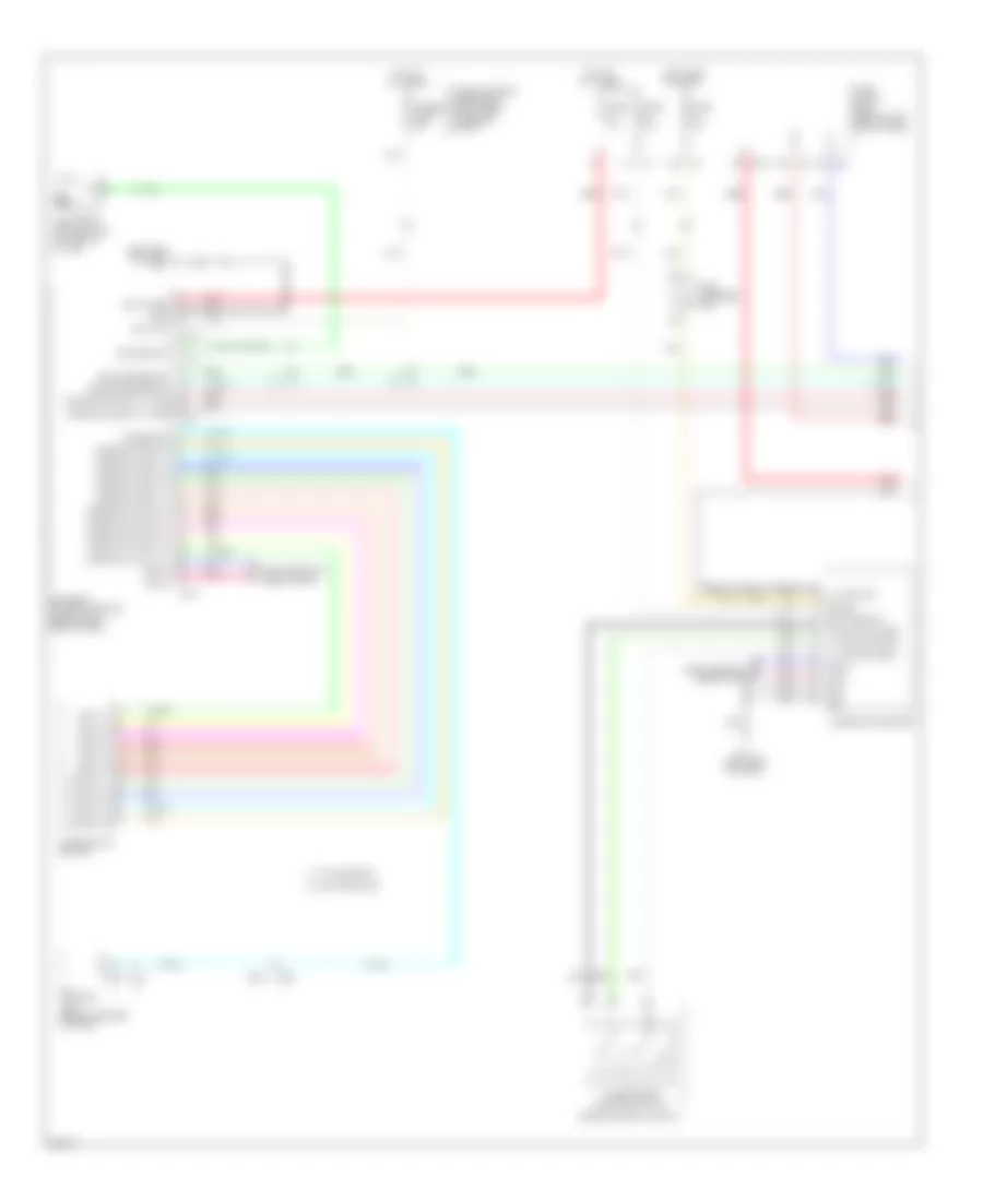
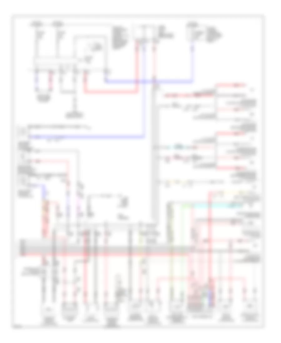
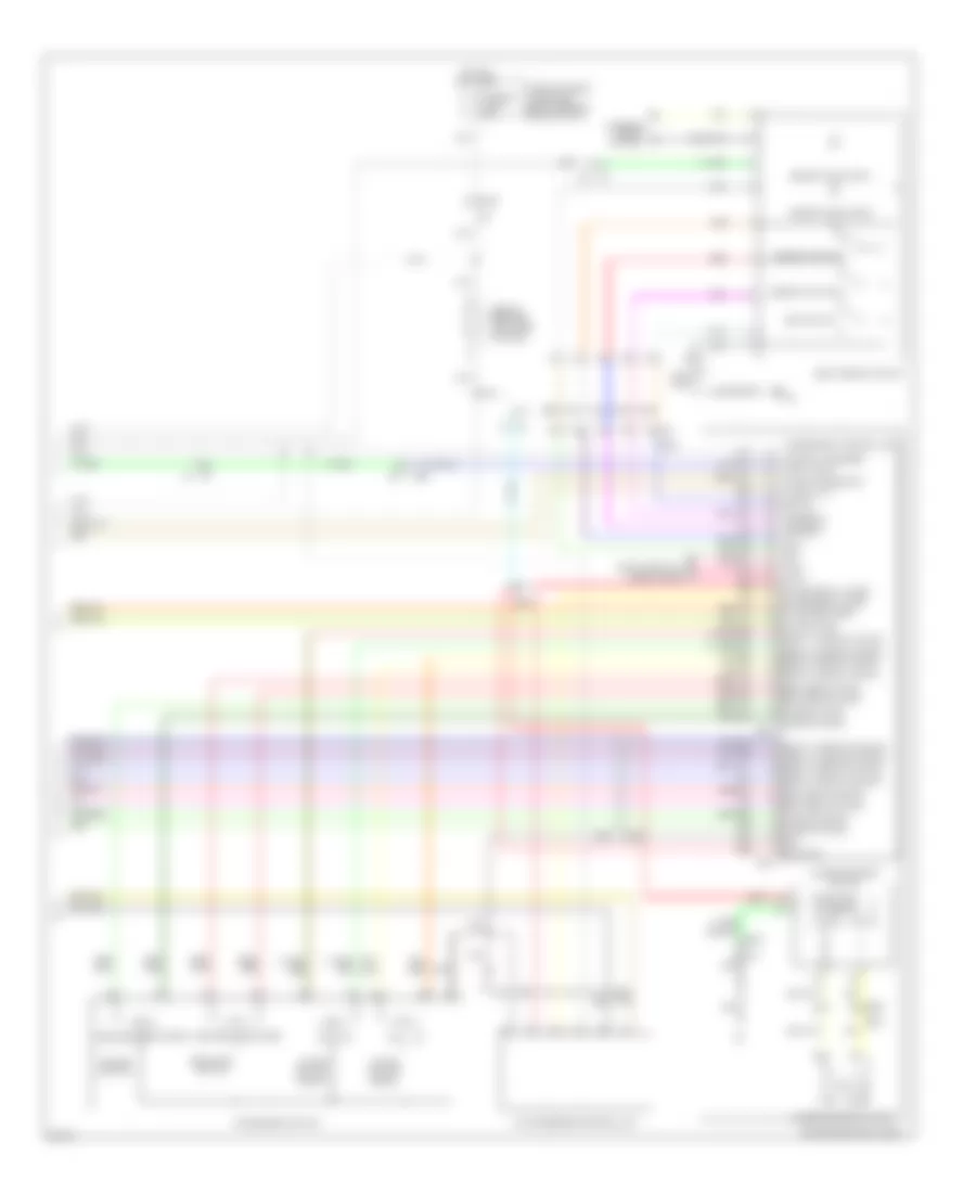
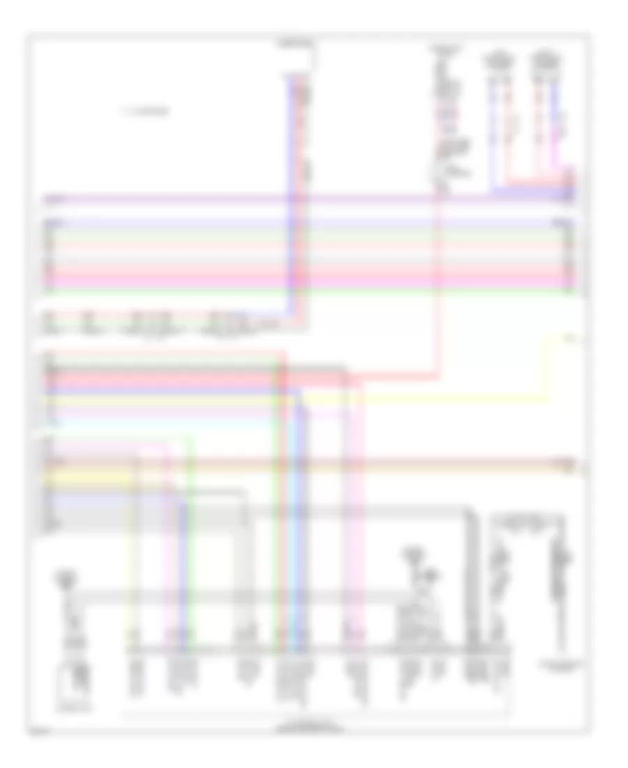
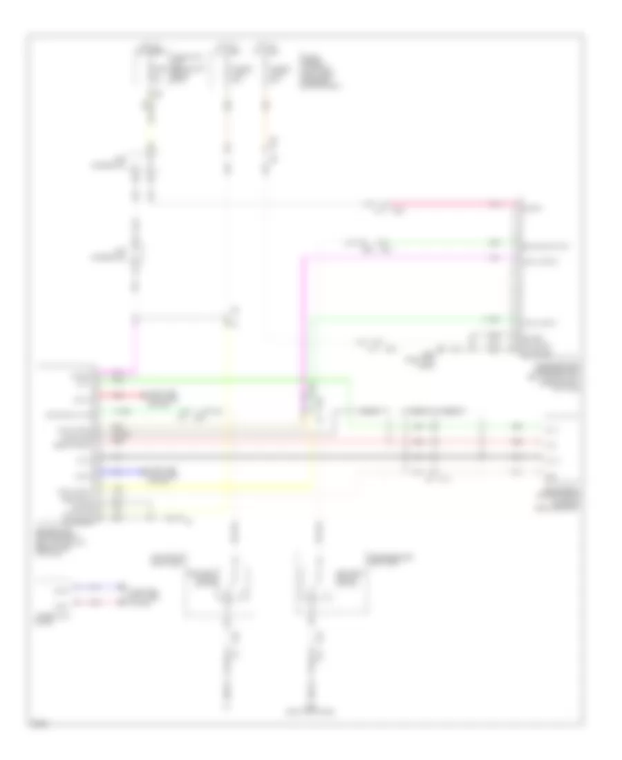
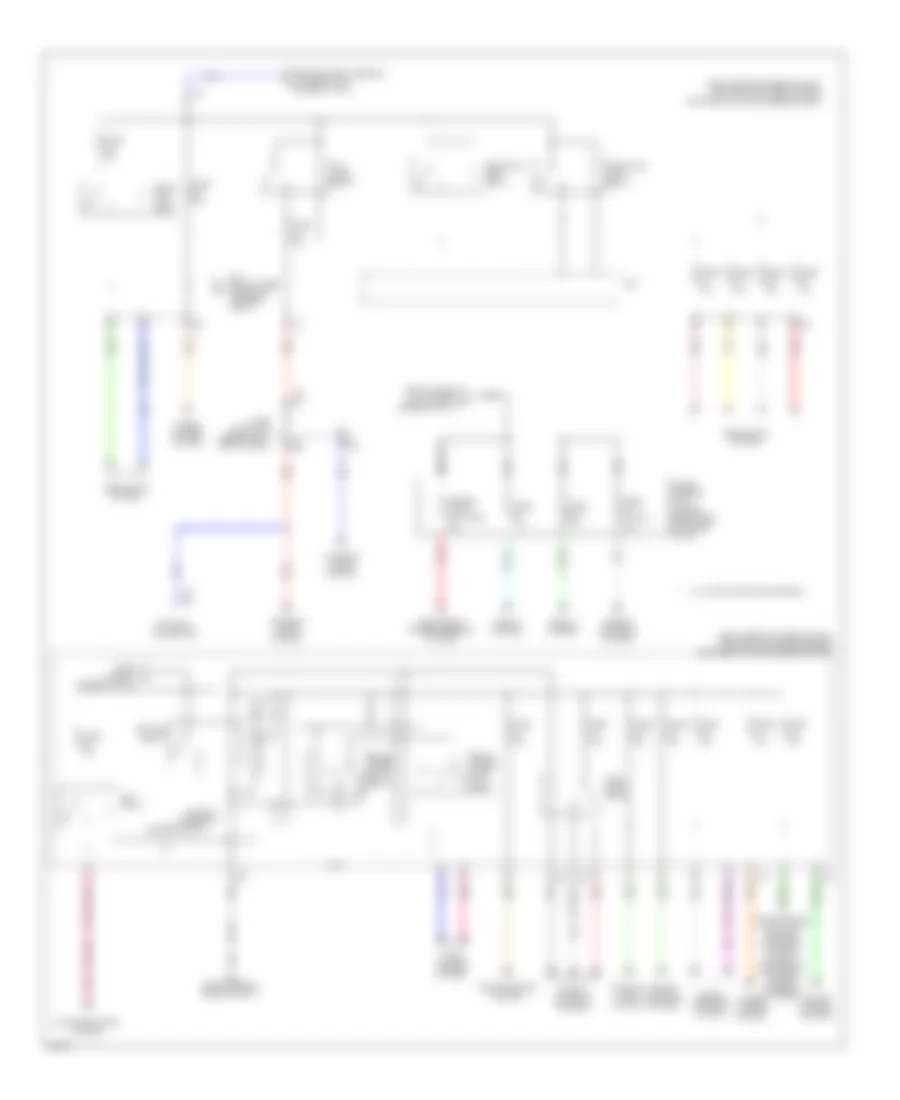
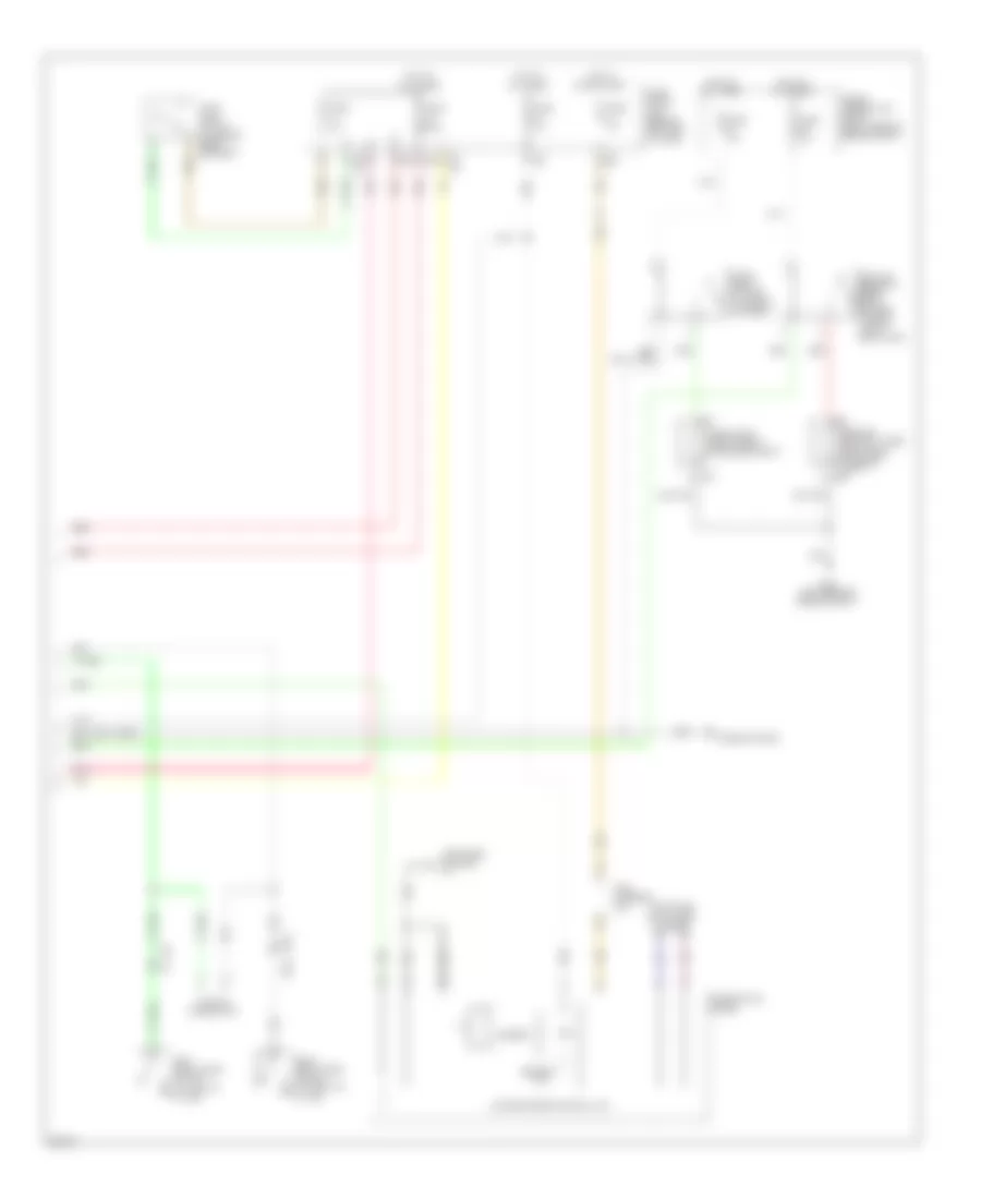
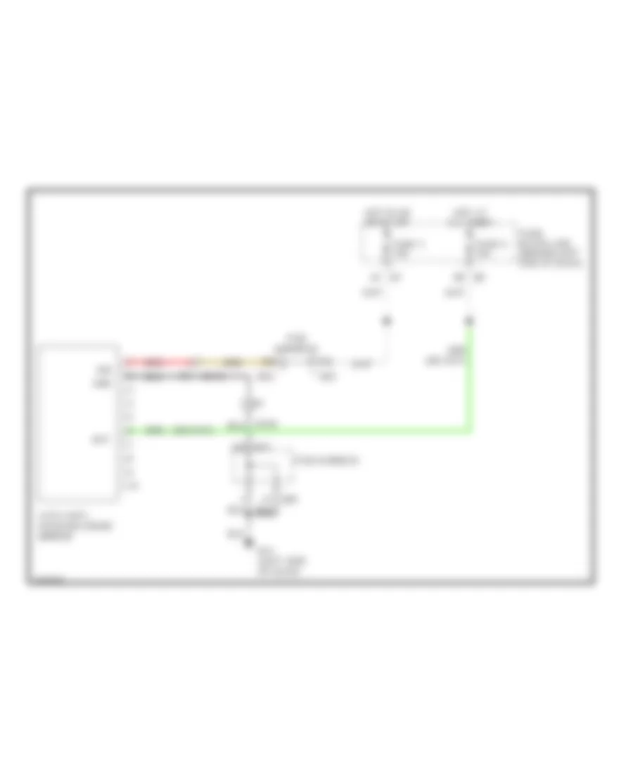
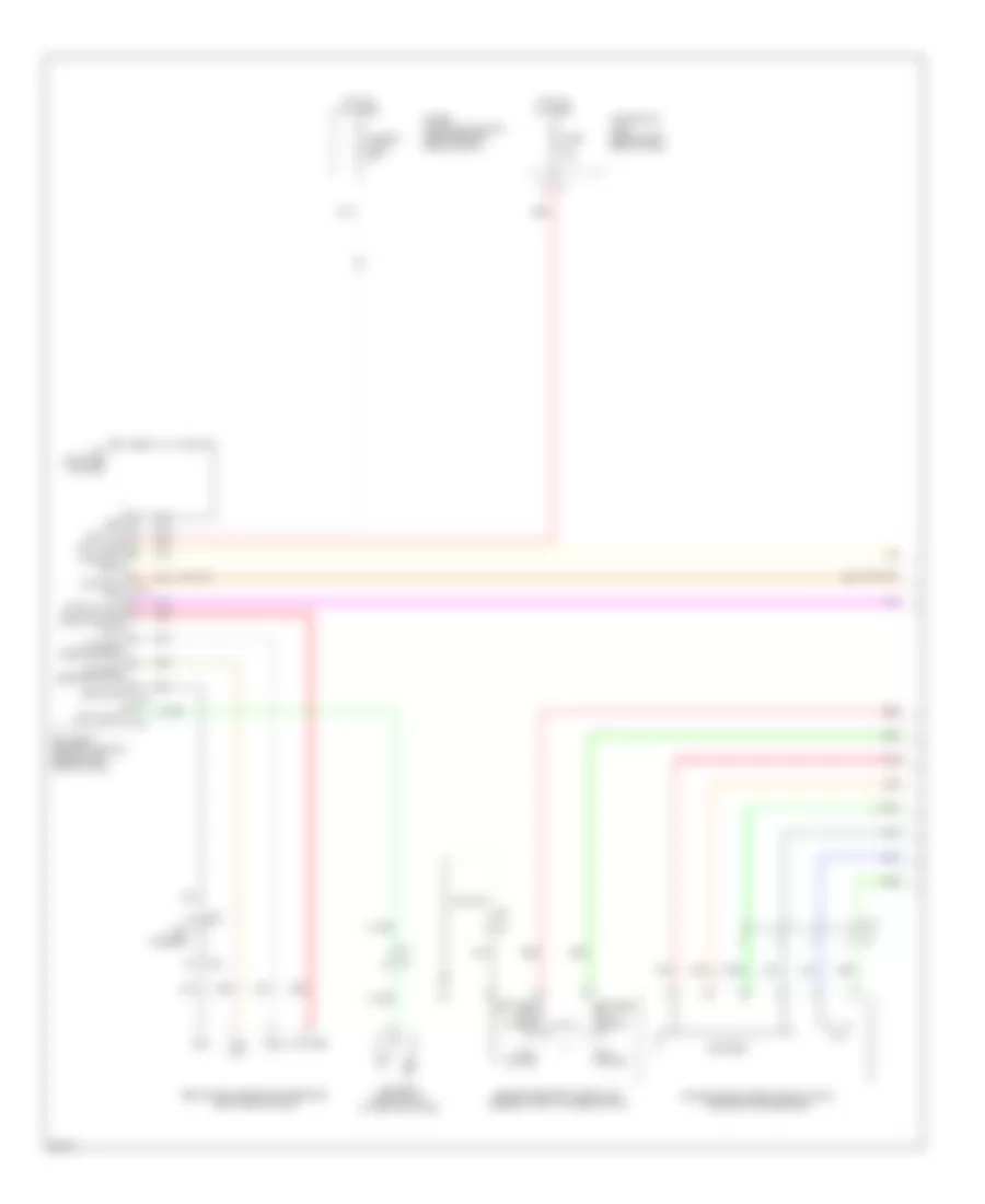
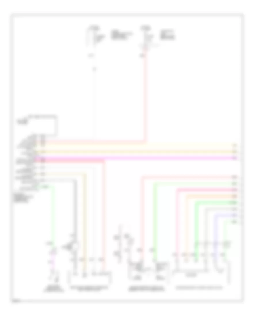
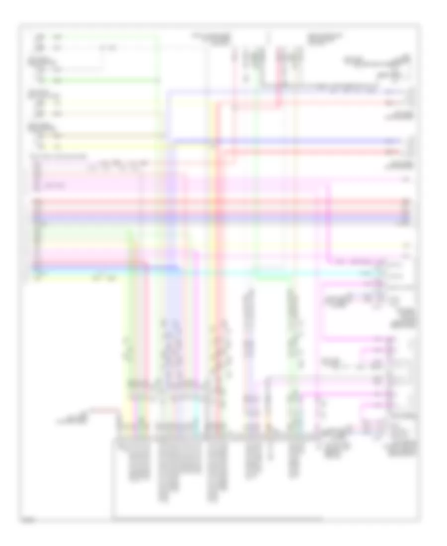
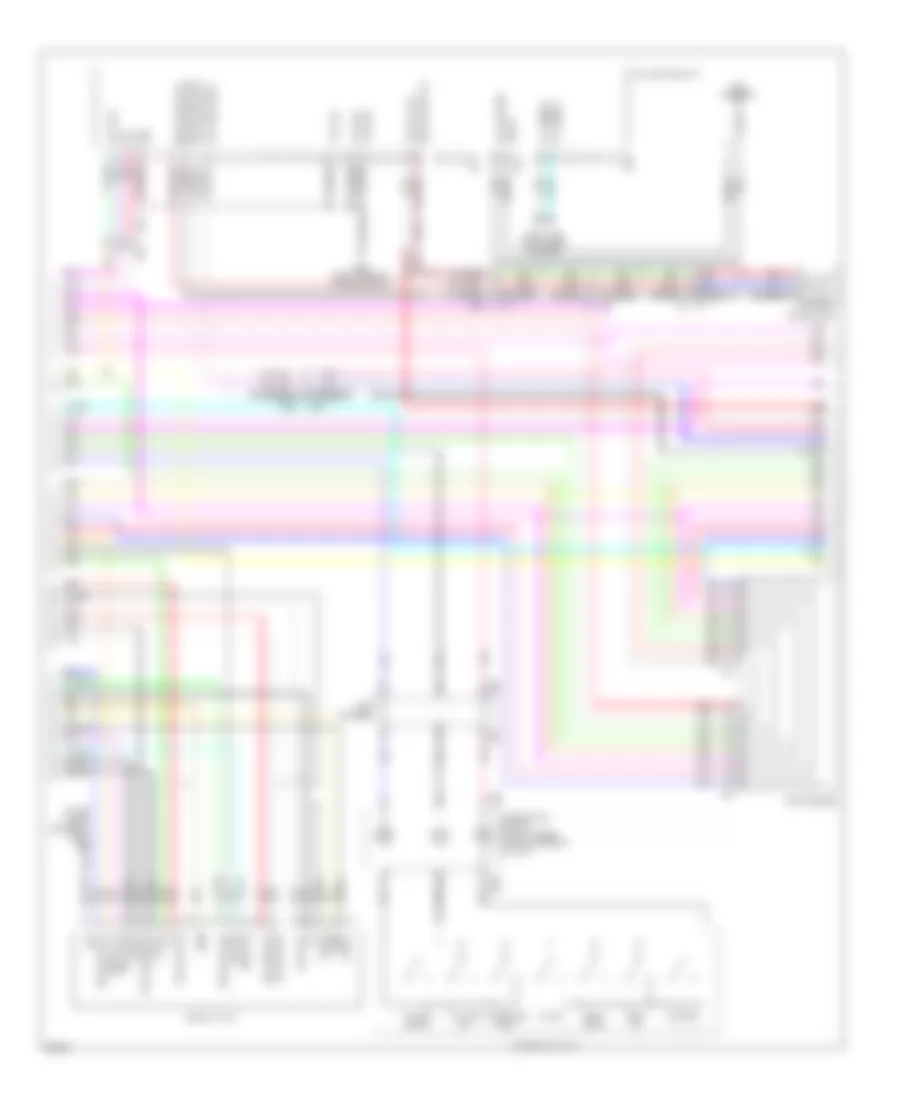
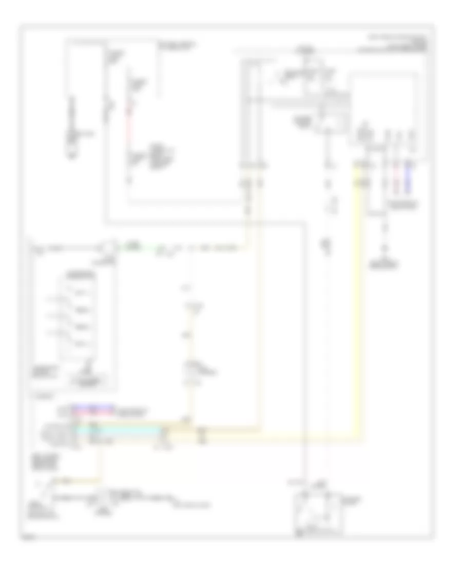
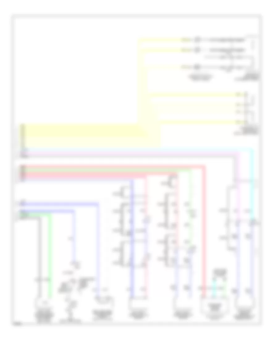
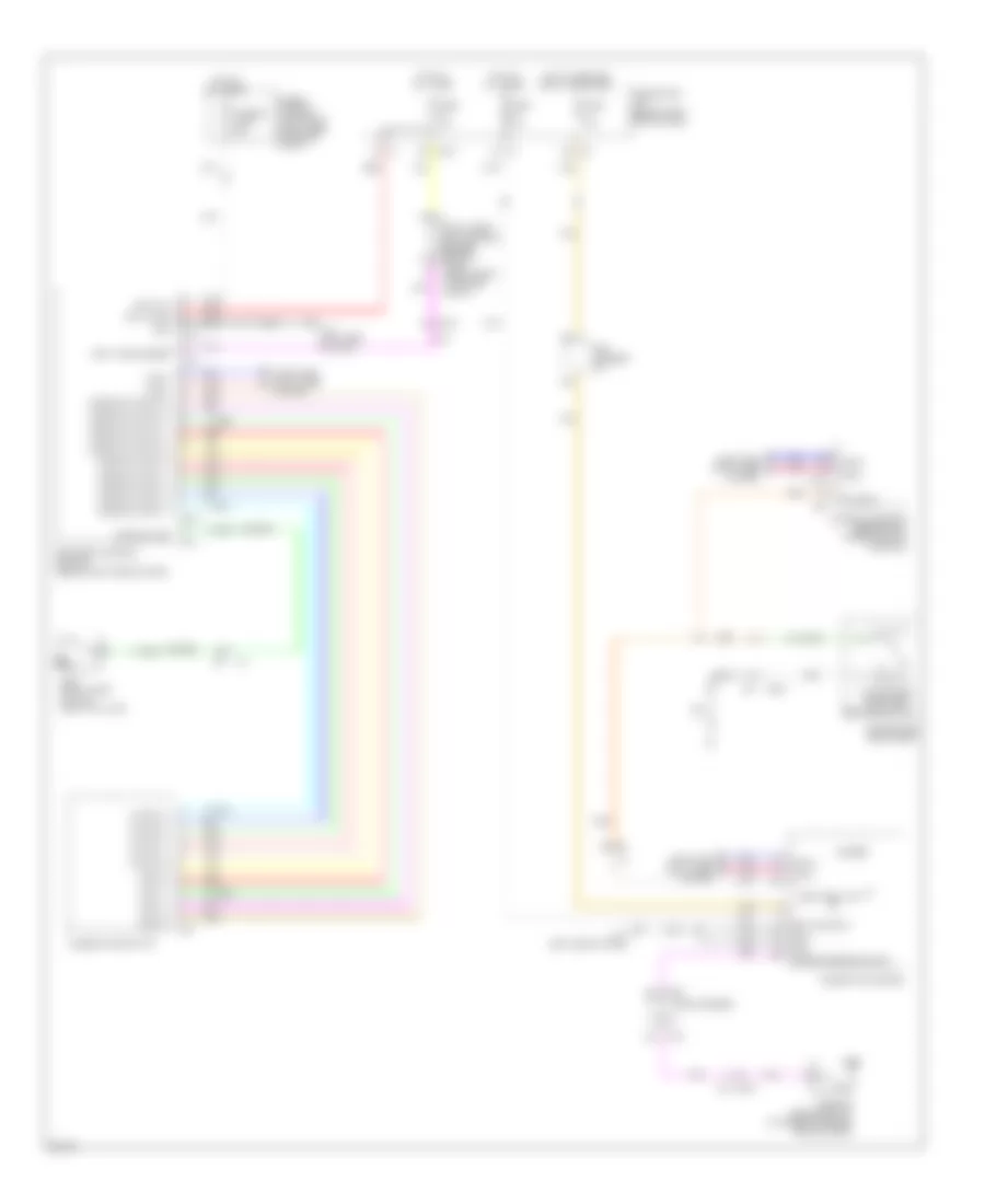
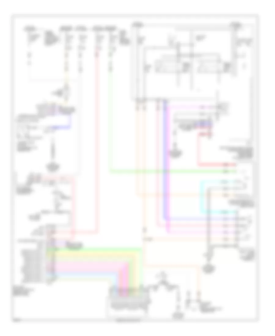
3.5L Hybrid, Automatic A/C Wiring Diagram (4 of 4) for Infiniti Q70 5.6 2014
List of elements for 3.5L Hybrid, Automatic A/C Wiring Diagram (4 of 4) for Infiniti Q70 5.6 2014:
- (lower left center of dash) (w/ forest air) inside odor detecting sensor
- (right side of engine compt) e46
- Comm line
- Computer data lines system
- Cooling fan control module (behind left side of radiator)
- Cooling fan motor 1 (behind right side of radiator)
- Cooling fan motor 2 (behind left side of radiator)
- Cooling fan relay (in fuse, fusible link & relay box)
- Cpu
- E106
- E301
- E302
- E37
- E46 (right side of engine compt)
- Ecm (engine control module) (right end of dash)
- Engine controls system
- Engine coolant
- Engine coolant temperature sensor (rear of left cylinder bank)
- F102
- Fuse & fusible link block (on battery positive post)
- Fuse 10a
- Fusible link g 50a
- Gnd
- Hot at all times
- Ign
- Ignition relay
- Ipdm e/r (intelligent power distribution module engine room) (right rear of engine compt)
- M105
- M107
- M11 (left side of dash)
- M181
- M20
- M23
- M28
- M29
- M30
- Nca
- Pcb harness
- Pnk
- Pwm-pwr
- Pwm-sig
- Red
- Refrigerant pressure sensor
- Refrigerant pressure sensor (right front of engine compt)
- Sens grd
- Sens sig
- Sensor ground
- Tan
- Temperature sensor
3.7L
3.7L, Automatic A/C Wiring Diagram (1 of 4) for Infiniti Q70 5.6 2014
List of elements for 3.7L, Automatic A/C Wiring Diagram (1 of 4) for Infiniti Q70 5.6 2014:
- (behind left side of dash) bcm (body control module)
- (left side of dash) m11
- A/c auto amp (right end of dash)
- Acc pwr sply
- Ambie sens sig
- Ambient sensor (front center of engine compt)
- Bat pwr sply
- Blower relay
- Blwr mtr f/b sig
- Blwr rly cont
- Can-h
- Can-l
- Computer data lines system
- Detecting sens sig
- Drv mode select sw (eco)
- Drv mode select sw (snow)
- Drv mode slt sw (sport)
- Drv mode slt sw (standard)
- E101
- E103
- E106
- Ecv ctrl sig
- Exh gas/outside odor
- Fuse 10a
- Fuse 15a
- Fuse block (j/b) (behind left end of dash)
- Fusible link e 100a
- Fusible link holder (right side of engine compt)
- Gnd
- Heated str whl rl ctrl sig
- Heated str whl sw sig
- Hmd sens (data) sig
- Hmd sens (sck) sig
- Hmd sens gnd
- Hot at all times
- Hot in acc or on
- Hot in on or start
- Humidity sens sig
- Humidity sensor (w/ forest air) (top center of windshield)
- Ign pwr sply
- In-vehicle sens sig
- In-vehicle sensor (behind left side of dash)
- Inside odor detecting sens sig
- Ionizer ctrl sig
- M110
- M120
- M123
- M20
- M22
- M23
- M24
- M30
- M66
- M67
- Pcb harness
- Pnk
- Pwr transistor ctrl sig
- Red
- Seats system
- Sens pwr sply
- Sunload sens (pass) sig
- Sunload sensor (dr) sig
- Sunload sensor (top right side of dash)
- Tan
3.7L, Automatic A/C Wiring Diagram (2 of 4) for Infiniti Q70 5.6 2014
List of elements for 3.7L, Automatic A/C Wiring Diagram (2 of 4) for Infiniti Q70 5.6 2014:
- (right side of dash) m95
- Aroma motor (w/ forest air)
- Blower motor (lower right side of dash)
- Drive mode select switch
- Eco
- Fan f/b
- Fanout
- Gnd
- Intake door motor (left side of blower unit)
- Intake sensor (left side of hvac unit)
- M135
- M201
- M26
- M28
- M30
- M95 (right side of dash)
- Pcb harness
- Power transistor (near blower motor)
- Red
- Right mode door motor (right side of hvac unit)
- Sig
- Snow
- Sport
- Standard
- Tan
- Upper ventilation door motor (upper left side of hvac unit)
- W/ forest air
- W/o forest air
3.7L, Automatic A/C Wiring Diagram (3 of 4) for Infiniti Q70 5.6 2014
List of elements for 3.7L, Automatic A/C Wiring Diagram (3 of 4) for Infiniti Q70 5.6 2014:
- (left rear of engine compt) e22
- A/c auto amp (right end of dash)
- Air mix door motor (dr) cooldrv sig
- Air mix door motor (dr) hot drv sig
- Air mix door motor (dr) pbr f/b sig
- Air mix door motor (pass) cool drv sig
- Air mix door motor (pass) hot drv sig
- Air mix door motor (pass) pbr f/b sig
- Aqs power
- Aqs s gnd
- Aqs s output
- Aroma motor (fragrant wood) drv sig
- Aroma motor (leaf scent) drv sig
- Aroma motor pbr f/r sig
- Compressor (lower left front of engine)
- E20
- Each door motor pbr pwr sply
- Ecv
- Exhaust gas outside odor detecting sensor (w/ forest air) (front of engine compt)
- F103
- F40
- F43
- F44
- Gnd
- Ign
- Inside odor detecting sensor (w/ forest air) (lower left center of dash)
- Intake door motor fre drv sig
- Intake door motor pbr f/b sig
- Intake door motor rec drv sig
- Intake sens gnd/each door motor pbr gnd
- Intake sens sig
- Ion on/off
- Ionizer (w/ forest air) (top left end of dash)
- Left air mix door motor (lower left side of hvac unit)
- Left mode door motor (left side of hvac unit)
- M105
- M11 (left side of dash)
- M116
- M181
- M20
- M23
- M28
- M304
- M6 e106
- Magnet clutch
- Mode door motor (dr) def drv sig
- Mode door motor (dr) pbr f/b sig
- Mode door motor (dr) vent drv sig
- Mode door motor (pass) def drv sig
- Mode door motor (pass) pbr f/b sig
- Mode door motor (pass) vent drv sig
- Pcb harness
- Pnk
- Rear mode door motor (on rear hvac duct assembly)
- Red
- Right air mix door motor (lower right side of hvac unit)
- Rr mode door motor foot drv sig
- Rr mode door motor pbr f/b sig
- Rr mode door motor vent drv sig
- Sens grd
- Sens sig
- Tan
- Up vent door motor (dr) cls drv sig
- Up vent door motor open drv sig
- Up vent door motor pbr f/b sig
- W/ forest air
- W/o forest air
3.7L, Automatic A/C Wiring Diagram (4 of 4) for Infiniti Q70 5.6 2014
List of elements for 3.7L, Automatic A/C Wiring Diagram (4 of 4) for Infiniti Q70 5.6 2014:
- (right side of engine compt) e46
- A/c relay
- Avcc2 pdpres ftpres
- Battery terminal w/ fusible link
- Computer data lines system
- Cooling fan control module (behind radiator)
- Cooling fan motor 1 (behind left side of radiator)
- Cooling fan motor 2 (behind right side of radiator)
- Cooling fan relay 1 (in fuse, fusible link & relay box)
- Cpu
- E106
- E301
- E302
- E37
- E46 (right side of engine compt)
- Ecm (engine control module) (right rear of engine compt)
- Engine controls system
- Engine coolant temperature sensor (left rear of engine)
- F102
- Fuse 10a
- Fusible link d 80a
- Fusible link holder 1
- Fusible link o 50a
- Gnda-o2s-tw -to
- Gnda-pdpres ftpres
- Hot at all times
- Ignition relay
- Ipdm e/r (intelligent power distribution module engine room) (right rear of engine compt)
- M107
- M28
- M29
- M30
- Nca
- Pcb harness
- Pdpres
- Pnk
- Red
- Refrigerant pressure sensor (right front of engine compt)
- Tan
- Veh can-h1
- Veh can-l1
5.6L
5.6L, Automatic A/C Wiring Diagram (1 of 4) for Infiniti Q70 5.6 2014
List of elements for 5.6L, Automatic A/C Wiring Diagram (1 of 4) for Infiniti Q70 5.6 2014:
- (behind left side of dash) bcm (body control module)
- (left side of dash) m11
- A/c auto amp (right end of dash)
- Acc pwr sply
- Ambie sens sig
- Ambient sensor (front center of engine compt)
- Bat pwr sply
- Blower relay
- Blwr mtr f/b sig
- Blwr rly cont
- Can-h
- Can-l
- Computer data lines system
- Detecting sens sig
- Drv mode slt sw (eco)
- Drv mode slt sw (snow)
- Drv mode slt sw (sport)
- Drv mode slt sw (standard)
- E101
- E103
- E106
- Ecv ctrl sig
- Exh gs/outside odor
- Fuse 10a
- Fuse 15a
- Fuse block (j/b) (behind left end of dash)
- Fusible link e 100a
- Fusible link holder (right side of engine compt)
- Gnd
- Het ster whl rl ctrl sig
- Het ster whl sw sig
- Hmd sens (data) sig
- Hmd sens (sck) sig
- Hmd sens gnd
- Hot at all times
- Hot in acc or on
- Hot in on or start
- Humidity sens sig
- Humidity sensor (w/ forest air) (top center of windshield)
- Ign pwr sply
- In-vehicle sens sig
- In-vehicle sensor (behind left side of dash)
- Inside odor detecting sens sig
- Ionizer ctrl sig
- M1 2a
- M110
- M120
- M123
- M20
- M22
- M23
- M24
- M30
- M66
- M67
- Pcb harness
- Pnk
- Pwr tran ctrl sig
- Red
- Seats system
- Sens pwr sply
- Sunload sens (pass) sig
- Sunload sensor (dr) sig
- Sunload sensor (top right side of dash)
- Tan
5.6L, Automatic A/C Wiring Diagram (2 of 4) for Infiniti Q70 5.6 2014
List of elements for 5.6L, Automatic A/C Wiring Diagram (2 of 4) for Infiniti Q70 5.6 2014:
- (right side of dash) m95
- Aroma motor (w/ forest air)
- Blower motor (lower right side of dash)
- Drive mode select switch
- Eco
- Fan f/b
- Fanout
- Gnd
- Intake door motor (left side of blower unit)
- Intake sensor (left side of hvac unit)
- M135
- M201
- M26
- M28
- M30
- M95 (right side of dash)
- Pcb harness
- Power transistor (near blower motor)
- Red
- Right mode door motor (right side of hvac unit)
- Sig
- Snow
- Sport
- Standard
- Tan
- Upper ventilation door motor (upper left side of hvac unit)
- W/ forest air
- W/o forest air
5.6L, Automatic A/C Wiring Diagram (3 of 4) for Infiniti Q70 5.6 2014
List of elements for 5.6L, Automatic A/C Wiring Diagram (3 of 4) for Infiniti Q70 5.6 2014:
- (left rear of engine compt) e22
- A/c auto amp (right end of dash)
- Air mix door motor (dr) cooldrv sig
- Air mix door motor (dr) hot drv sig
- Air mix door motor (dr) pbr f/b sig
- Air mix door motor (pass) cool drv sig
- Air mix door motor (pass) hot drv sig
- Air mix door motor (pass) pbr f/b sig
- Aqs power
- Aqs s gnd
- Aqs s output
- Aroma motor (fragrant wood) drv sig
- Aroma motor (leaf scent) drv sig
- Aroma motor pbr f/r sig
- Compressor (lower left front of engine)
- E106 m6
- E20
- Each door motor pbr pwr sply
- Ecv
- Exhaust gas outside odor detecting sensor (w/ forest air) (front of engine compt)
- F103
- F40
- F43
- F44
- Gnd
- Ign
- Inside odor detecting sensor (w/ forest air) (lower left center of dash)
- Intake door motor fre drv sig
- Intake door motor pbr f/b sig
- Intake door motor rec drv sig
- Intake sens gnd/each door motor pbr gnd
- Intake sens sig
- Ion on/off
- Ionizer (w/ forest air) (top left end of dash)
- Left air mix door motor (lower left side of hvac unit)
- Left mode door motor (lower left side of hvac unit)
- M105
- M11 (left side of dash)
- M116
- M181
- M20
- M23
- M28
- M304
- Magnet clutch
- Mode door motor (dr) def drv sig
- Mode door motor (dr) pbr f/b sig
- Mode door motor (dr) vent drv sig
- Mode door motor (pass) def drv sig
- Mode door motor (pass) pbr f/b sig
- Mode door motor (pass) vent drv sig
- Pcb harness
- Pnk
- Rear mode door motor (on rear hvac duct assembly)
- Red
- Right air mix door motor (lower right side of hvac unit)
- Rr mode door motor foot drv sig
- Rr mode door motor pbr f/b sig
- Rr mode door motor vent drv sig
- Sens grd
- Sens sig
- Tan
- Up vent door motor (dr) cls drv sig
- Up vent door motor open drv sig
- Up vent door motor pbr f/b sig
- W/ forest air
- W/o forest air
5.6L, Automatic A/C Wiring Diagram (4 of 4) for Infiniti Q70 5.6 2014
List of elements for 5.6L, Automatic A/C Wiring Diagram (4 of 4) for Infiniti Q70 5.6 2014:
- A/c relay
- Battery terminal w/ fusible link
- Comm line
- Computer data lines system
- Cooling fan control module 1 (behind left side of radiator)
- Cooling fan control module 2 (behind right side of radiator)
- Cooling fan motor 1 (behind left side of radiator)
- Cooling fan motor 2 (behind right side of radiator)
- Cooling fan relay 1 (in fuse, fusible link & relay box)
- Cooling fan relay 2 (in fusible link holder)
- Cpu
- E106
- E301
- E303
- E37
- E39
- E46 (right side of engine compt)
- Ecm (engine control module) (right rear of engine compt)
- Engine controls system
- Engine coolant
- Engine coolant temperature sensor (right rear of engine)
- F110
- Fuse 10a
- Fusible link d 80a
- Fusible link holder 1
- Fusible link holder 2
- Fusible link o 50a
- Fusible link r 50a
- Hot at all times
- Ignition relay
- Ipdm e/r (intelligent power distribution module engine room) (right rear of engine compt)
- M160
- M28
- M29
- M30
- Nca
- Pcb harness
- Pnk
- Red
- Refrigerant pressure sensor
- Refrigerant pressure sensor (right front of engine compt)
- Sensor ground
- Tan
- Temperature sensor
ANTI-LOCK BRAKES
Anti-lock Brakes Wiring Diagram, Except Hybrid (1 of 2) for Infiniti Q70 5.6 2014
List of elements for Anti-lock Brakes Wiring Diagram, Except Hybrid (1 of 2) for Infiniti Q70 5.6 2014:
- (0r pnk)
- (left side of engine compt) e43
- (or pnk)
- (or red)
- 12v
- Abs actuator & electric unit (control unit) (left rear of engine compt)
- Adas control unit (w/ icc) (rear of vehicle)
- B29
- B30
- Bus-h
- Bus-l
- Can-h
- Can-l
- Canm2(+)
- Canm2(-)
- Computer data lines system
- E106
- Ecu(gnd)
- Fr-lh sen(pwr)
- Fr-lh sen(sig)
- Fr-rh sen(pwr)
- Fr-rh sen(sig)
- Fuse & fusible link block (right rear of engine compt)
- Fuse 46 10a
- Fusible link m 30a
- Fusible link n 50a
- Gnd
- Hot at all times
- Hot in on or start
- Ign
- Ign(pwr)
- Ipdm e/r (intelligent power distribution module engine room) (right rear of engine compt)
- Left rear wheel sensor (on left rear wheel hub assembly)
- M105
- M11 (left side of dash)
- M135
- M181
- M20
- M201 red (0r pnk)
- M22
- M23
- M26
- M28
- M30
- M6 red (0r pnk)
- M7 b1
- M95 (right side of dash)
- Motor(gnd)
- Mtr(pwr)
- Out sig
- Pcb harness
- Pnk
- Red
- Right rear wheel sensor (on right rear wheel hub assembly)
- Rr-lh sen(pwr)
- Rr-lh sen(sig)
- Rr-rh sen(pwr)
- Rr-rh sen(sig)
- Shield
- Sol(pwr)
- Steering angle sensor (on steering column)
- Stp sw
- Triple switch
- Vac sen(gnd)
- Vac sen(pwr)
- Vac sen(sig)
- Vacuum sensor (below brake master cylinder)
- Vcc (+5v)
- Vdc off sw
- Vdc off switch
- W/ 4was
- W/ icc & 4was
- W/o 4was
- W/o icc & 4was
- Yaw rate/ side/decel g sensor (under center console)
Anti-lock Brakes Wiring Diagram, Except Hybrid (2 of 2) for Infiniti Q70 5.6 2014
List of elements for Anti-lock Brakes Wiring Diagram, Except Hybrid (2 of 2) for Infiniti Q70 5.6 2014:
- (or red)
- 12c
- A/c auto amp (right end of dash)
- Brake fluid level switch (left rear of engine compt)
- Brake sw
- Can-h
- Can-l
- Combination meter
- Computer data lines system
- Dr mod sel sw(eco)
- Dr mod sel sw(snow)
- Dr mod sel sw(sport)
- Dr mod sel sw(standard)
- Drive mode select switch
- E103
- E106
- E106 m6
- E22 (left rear of engine compt)
- Eco
- Exterior lights system
- Fuse 4 10a
- Fuse 7 10a
- Fuse 9 10a
- Fuse block (j/b) (behind left end of dash)
- Gnd
- Hot at all times
- Hot in on or start
- Ign
- Left front wheel sensor (on left front steering knuckle assembly)
- Level sw
- M11 (left side of dash)
- M135
- M135 m201
- M201
- M22
- M24
- M26
- M27
- M30
- M66
- M95 (right side of dash)
- Parking brake switch (at base of parking brake lever)
- Pcb harness
- Pnk
- Resistor (w/ icc)
- Right front wheel sensor (on right front steering knuckle assembly)
- Snow
- Sport
- Standard
- Stop lamp switch (on brake pedal bracket)
- Tan
- Vdc ind, vdc off ind, abs ind & brake ind
- W/ icc
- W/o icc
Anti-lock Brakes Wiring Diagram, Hybrid (1 of 3) for Infiniti Q70 5.6 2014
List of elements for Anti-lock Brakes Wiring Diagram, Hybrid (1 of 3) for Infiniti Q70 5.6 2014:
- (at high stop lamp assembly) (w/ intelligent cruise control) stop lamp off relay 2
- (behind left end of dash)
- (on brake pedal bracket) stop lamp switch
- (right rear of luggage compt) b224
- Abs actuator & electric unit (left rear of engine compt)
- Ascd brk sw sig
- B201
- B228
- B28
- B37 e19
- B5 b222
- Brake comm
- Brake switch (w/ intelligent cruise control) (on brake pedal bracket)
- Brake switch (w/o intelligent cruise control) (on brake pedal bracket)
- Can h
- Can l
- Computer data lines system
- Cruise control system
- E103
- E106
- E106 m6
- E119 b69
- E43 (left side of engine compt)
- Exterior lights system
- Fuse & fusible link block (on battery positive post)
- Fuse 10a
- Fuse block (j/b)
- Fusible link m 30a
- Fusible link n 50a
- G sens pwr sply
- G sensor sig (+)
- G sensor sig (-)
- G snsr gnd
- Gnd
- Hot at all times
- Hot in on or start
- Ign
- Left front wheel sensor
- Left rear wheel sensor
- Lf sens pwr sply
- Lf sens sig
- Lr sens pwr sply
- Lr sens sig
- M117
- Motor battery
- Pnk
- Press sens gnd
- Press sens pwr sply
- Press sens sig
- Red
- Rf sens pwr sply
- Rf sens sig
- Right front wheel sensor
- Right rear wheel sensor
- Rr sens pwr sply
- Rr sens sig
- Shift interlock system
- Stop lamp off relay 1 (w/ intelligent cruise control) (at high stop lamp assembly)
- Stop lamp sw sig
- Valve battery
- Vdc off sw
- W/ intelligent cruise control
- W/o intelligent cruise control
Anti-lock Brakes Wiring Diagram, Hybrid (2 of 3) for Infiniti Q70 5.6 2014
List of elements for Anti-lock Brakes Wiring Diagram, Hybrid (2 of 3) for Infiniti Q70 5.6 2014:
- (left side of dash)
- A/c auto amp (right end of dash)
- Abs, vdc, vdc off & brake ind
- Brake fluid level switch
- Brake fluid sw sig
- Can-h
- Can-l
- Combination meter
- Computer data lines system
- Dr mod sel sw(eco)
- Dr mod sel sw(snow)
- Dr mod sel sw(sport)
- Dr mod sel sw(standard)
- Drive mode select switch
- E106
- E22 (left rear of engine compt)
- E46 (right side of engine compt)
- Eco
- M11
- M135
- M181 m105
- M20
- M201
- M22
- M23
- M24
- M26
- M30
- M6 e106
- M66
- M95 (right side of dash)
- Master cylinder pressure sensor 2
- Parking brake switch
- Parking brk sw sig
- Pcb harness
- Pnk
- Red
- Shield
- Snow
- Sport
- Standard
- Tan
- Triple switch
- Vdc off switch
- Yaw rate/side/ decel g sensor
Anti-lock Brakes Wiring Diagram, Hybrid (3 of 3) for Infiniti Q70 5.6 2014
List of elements for Anti-lock Brakes Wiring Diagram, Hybrid (3 of 3) for Infiniti Q70 5.6 2014:
- (left rear of engine compt) e22
- (left side of dash) m11
- (left side of rear bumper) b61
- 10a
- B-in
- B-out
- B245
- B33
- B69
- Battery terminal w/ fusible link
- Brake comm
- Brake pwr sply
- Brake pwr sply backup comm
- Buzzer pwr sply
- Buzzer sig
- C10
- Can-h
- Can-l
- Can1-h
- Can1-l
- Can2-h
- Can2-l
- Computer data lines system
- Ctrl module battery
- Dlc-wake-up
- E105
- E106
- E119
- E19 b37
- E46 (right side of engine compt)
- E63
- Electrically-driven intelligent brake unit
- Fuse & fusible link block 3 (on battery positive post)
- Fuse 10a
- Fuse 15a
- Fuse 46
- Fusible link d 50a
- Gnd
- Hot at all times
- Hot in on or start
- Ign
- Ipdm e/r (intelligent power distribution module engine room) (right rear of engine compt)
- Lin
- M20
- M22
- M27
- M30
- M95 (right side of dash)
- Master cylinder pressure sensor 1
- Motor battery
- Pcb harness
- Pnk
- Press sens gnd
- Press sens pwr sply
- Press sens sig
- Red
- Resistor (w/ intelligent cruise control)
- Shield
- Steering angle sensor (on steering column)
- Stop lamp sw sig
- Stp lmp off rly sig
- Stroke sens 1 sig
- Stroke sens 2 sig
- Stroke sens gnd
- Stroke sens pwr sply
- Stroke sensor
- Warning buzzer
ANTI-THEFT
Forced Entry Wiring Diagram, Except Hybrid (1 of 4) for Infiniti Q70 5.6 2014
List of elements for Forced Entry Wiring Diagram, Except Hybrid (1 of 4) for Infiniti Q70 5.6 2014:
- (in right front door)
- (left side of dash) m11
- A/t shift
- Acc ind
- B1 m7
- B201
- B40 b240
- Bat (f/l)
- Bat (fuse)
- Bcm (body control module) (behind left side of dash)
- Between full stroke & n
- Can-h
- Can-l
- Computer data lines system
- Console inside key antenna (under rear of center console)
- D1 b4
- D18
- D19 d9
- D31 b204
- D8 d18
- Dongle link
- Door key cylinder switch
- Door lock & unlock switch
- Door lock actuator
- Dr door request sw
- Dr sw (rr lh)
- Dr sw (rr rh)
- Dr unlock out (rr)
- Driver door ant+
- Driver door ant-
- Driver side front door lock assembly (in left front door)
- Drv dr sw
- Drv dr unlck sen
- Exterior lights system
- Fuel lid lck out
- Fuel lid unlck out
- Full stroke
- Fuse & fusible link block (right rear of engine compt)
- Fusible link l 40a
- Gnd
- Hot at all times
- I-key warn buzzer
- Ign rly
- Instrument center inside key antenna (under front of center console)
- Interior lights system
- Keyless receiver comm
- Keyless receiver rssi
- Left front outside handle assembly (request switch)
- Lh turn sig out
- Lock
- Lock ind
- M117
- M120
- M121
- M122
- M123
- M181 m105
- M21
- M26
- M7 b1
- Nca
- On ind
- P position
- P/n position
- Pass door request sw
- Pass dr sw
- Pass dr unlock out
- Passenger door ant+
- Passenger door ant-
- Passenger side front door lock assembly
- Pcb harness
- Pcb harness m22
- Pnk
- Power window main switch
- Push sw
- Pwr sply
- Pwr wdw sw comm
- Rear bmpr ant+
- Rear bmpr ant-
- Rear bumper outside key antenna (behind center of rear bumper)
- Reciever/sensor gnd
- Red
- Rh turn sig out
- Room ant1+
- Room ant1-
- Room ant2+
- Room ant2-
- Room lamp timer cont
- Security ind cont
- Shield
- St rly cont
- Stop lamp sw1
- Stop lamp sw2
- T13 b276
- Tan
- Tr key cylinder sw
- Tr lid op cancel sw
- Tr lid open out
- Tr lid open req sw
- Tr lid opnr sw
- Tr room lamp sw
- Trunk room ant+
- Trunk room ant-
- Trunk room inside key antenna (under center of rear parcel shelf)
- Unlock
- Unlock sensor
Forced Entry Wiring Diagram, Except Hybrid (2 of 4) for Infiniti Q70 5.6 2014
List of elements for Forced Entry Wiring Diagram, Except Hybrid (2 of 4) for Infiniti Q70 5.6 2014:
- (at right "c" pillar) right rear door switch
- (rear of left rear door) left rear door lock assembly
- (rear of right rear door) right rear door lock assembly
- (right rear quarter panel)
- (right side of luggage compt) fuel lid lock actuator
- Acc
- B1 m7
- B201
- B201 m117
- B202 (right kick panel)
- B204
- B224
- B240
- B276
- B40
- Batt
- Closer switch
- D1 b4
- D31
- D31 b204
- D51 b18
- D71 b218
- Driver side outside key antenna
- Gnd remote keyless entry receiver (right end of dash)
- Ill
- Interior lights system
- Lock
- M11 (left side of dash)
- M117
- M181 m105
- M20
- M23
- M95 (right side of dash)
- Passenger side outside key antenna
- Pcb harness
- Pcb harness m30
- Pnk
- Push switch
- Push- button ignition switch
- Red
- Right front outside handle assembly (request switch)
- Rssi
- Sig out
- Switch
- T13
- T13 b276
- Tan
- Trunk closer assembly
- Trunk closer control unit
- Trunk lid opener cancel switch
- Trunk lid opener request
- Trunk lid opener switch
Forced Entry Wiring Diagram, Except Hybrid (3 of 4) for Infiniti Q70 5.6 2014
List of elements for Forced Entry Wiring Diagram, Except Hybrid (3 of 4) for Infiniti Q70 5.6 2014:
- (at left "c" pillar) left rear door switch
- (left side of dash) m11
- (right front of engine compt) hood switch
- (right rear quarter panel) b224
- A/t assembly
- A/t shift selector (detention
- B1 m7
- B276 t13
- Can-h
- Can-l
- Computer data lines system
- Cpu
- Dongle unit (canada) (center of dash)
- E106
- E106 m6
- E20
- E46 (right side of engine compt)
- F40
- Gnd
- Head lights system
- Headlamp high relay
- Headlamp low relay
- Hot at all times
- Intelligent key warning buzzer (engine room) (right front of engine compt)
- Interface
- Ipdm e/r (intelligent power distribution module engine room) (right rear of engine compt)
- Joint connector
- M117 b201
- M20
- M22
- M24
- M26
- Nca
- Pcb harness
- Pnk
- Red
- Start rly
- Starter control relay
- Starter relay
- Starting/ charging system
- Switch)
- Transmission control module (tcm)
- Trunk key cylinder switch
Forced Entry Wiring Diagram, Except Hybrid (4 of 4) for Infiniti Q70 5.6 2014
List of elements for Forced Entry Wiring Diagram, Except Hybrid (4 of 4) for Infiniti Q70 5.6 2014:
- (left side of dash) m11
- 12c
- 12f
- Buzzer
- Combination meter
- Computer data lines system
- E103
- E22 (left rear of engine compt)
- E61
- E62
- E71
- E72
- Fuse & fusible link block (right rear of engine compt)
- Fuse 10a
- Fuse 15a
- Fuse block (j/b) (behind left end of dash)
- Horn (high) (right front of engine compt)
- Horn relay (in fuse & fusible link box)
- Horns system
- Hot at all times
- Hot in on or start
- Left front door switch (at left "b" pillar)
- M117 b201
- M7 b1
- Option connector
- Pcb harness m24
- Pnk
- Red
- Right front door switch (at right "b" pillar)
- Security ind
- Stop lamp switch (on brake pedal bracket)
- Tan
- Unified meter control unit
- Vehicle security horn (left front of engine compt)
- Vehicle security horn relay (in fuse, fusible link & relay box)
Forced Entry Wiring Diagram, Hybrid (1 of 4) for Infiniti Q70 5.6 2014
List of elements for Forced Entry Wiring Diagram, Hybrid (1 of 4) for Infiniti Q70 5.6 2014:
- (left side of dash) m11
- (or red)
- A/t shift
- Acc ind
- As req sw
- B1 m7
- B201
- B24 (left rear quarter panel)
- B40 b240
- Bat (f/l)
- Bat (fuse)
- Bcm (body control module) (under left side of dash)
- Between full stroke & n
- Can-h
- Can-l
- Computer data lines system
- Console inside key antenna (in console)
- D1 b4
- D18
- D19 d9
- D22
- D31 b204
- D8 d18
- Dongle link
- Door lock & unlock switch
- Door lock actuator
- Dr door req sw
- Dr unlock out (rr)
- Driver door ant+
- Driver door ant-
- Driver side front door lock assembly
- Drv dr sw
- Drv dr unlck sen
- Eng start sw
- Exterior lights system
- Fuel lid lck out
- Fuel lid unlck out
- Full stroke
- Fuse & fusible link block (on battery positive post)
- Fusible link l 40a
- Gnd
- Hot at all times
- I-key warn buzzer
- Ign rly
- Instrument center inside key antenna (in dash)
- Interior lights system
- Key cylinder switch
- Keyless receiver comm
- Keyless receiver rssi
- Left front outside handle assembly (request switch)
- Lh turn sig out
- Lock
- Lock ind
- M117
- M120
- M121
- M122
- M123
- M181 m105
- M21
- M26
- M30
- M7 b1
- M95 (right side of dash)
- Nca
- On ind
- P position
- P/n position
- Pass dr sw
- Pass dr unlock out
- Passenger door ant+
- Passenger door ant-
- Passenger side front door lock assembly
- Pcb harness
- Pcb harness m22
- Pnk
- Power window main switch
- Pwr sply
- Pwr wdw sw comm
- Rear bmpr ant+
- Rear bmpr ant-
- Rear bumper outside key antenna (behind center of rear bumper fascia)
- Reciever/sensor gnd
- Red
- Rh turn sig out
- Room ant1+
- Room ant1-
- Room ant2+
- Room ant2-
- Room lamp timer cont
- Rr lh dr sw
- Rr rh dr sw
- Security ind cont
- Shield
- Starter rly cont
- Stop lamp sw1
- Stop lamp sw2
- T11 b262
- Tan
- Tr key cylinder sw
- Tr lid open req sw
- Tr lid open request trunk lid open/ close status tr lid op cancel sw
- Tr lid opnr sw
- Trunk room ant+
- Trunk room ant-
- Trunk room inside key antenna (inside cargo area)
- Unlock
- Unlock sensor
Forced Entry Wiring Diagram, Hybrid (2 of 4) for Infiniti Q70 5.6 2014
List of elements for Forced Entry Wiring Diagram, Hybrid (2 of 4) for Infiniti Q70 5.6 2014:
- (at right rear "c" pillar) right rear door switch
- (in driver's door handle) driver side outside key antenna
- (in passenger's door handle) passenger side outside key antenna
- (left side of dash) m11
- (right rear of luggage compt)
- Acc
- Ant+
- Ant-
- B201 m117
- B202
- B204
- B224
- B228 b28
- Batt
- D1 b4
- D31
- D31 b204
- D51 b18
- D71 b218
- Fuel lid lock actuator
- Gnd
- Ill
- Interior lights system
- Left rear door lock assembly
- Lock
- M181 m105
- M20
- M23
- M95 (right side of dash)
- Pcb harness
- Pcb harness m30
- Pnk
- Push switch
- Push- button ignition switch
- Red
- Remote keyless entry receiver (right side of dash)
- Right front outside handle assembly (request switch)
- Right rear door lock assembly
- Rssi
- Shield
- Sig out
- Switch
- Tan
- Trunk lid opener cancel switch
- Trunk lid opener request
- Trunk lid opener switch
Forced Entry Wiring Diagram, Hybrid (3 of 4) for Infiniti Q70 5.6 2014
List of elements for Forced Entry Wiring Diagram, Hybrid (3 of 4) for Infiniti Q70 5.6 2014:
- (at left rear "c" pillar) left rear door switch
- (left side of dash) m11
- A/t assembly
- A/t shift selector (detention
- B1 m7
- B159
- B224 (right rear of luggage compt)
- B262 t11
- Can-h
- Can-l
- Computer data lines system
- Cpu
- Dongle unit (canada)
- E106
- E106 m6
- E46 (right side of engine compt)
- Gnd
- Headlamp high relay
- Headlamp low relay
- Headlights system
- Hood switch
- Hot at all times
- Hpcm (behind center of rear seats)
- Intelligent key warning buzzer (right front of engine compt)
- Interface
- Ipdm e/r (intelligent power distribution module engine room) (right rear of engine compt)
- Joint connector
- M116 f103
- M117 b201
- M20
- M22
- M24
- M26
- M77 b44
- Pcb harness
- Pin sig
- Pnk
- Ready sig
- Red
- Shield
- Switch)
- Trans range sw
- Transmission control module (tcm)
- Trunk key cylinder switch
Forced Entry Wiring Diagram, Hybrid (4 of 4) for Infiniti Q70 5.6 2014
List of elements for Forced Entry Wiring Diagram, Hybrid (4 of 4) for Infiniti Q70 5.6 2014:
- (option connector)
- 12c
- 12f
- B201
- B201 m117
- B224 (right rear of luggage compt)
- B228
- B28
- Buzzer
- Combination meter
- Combination switch (spiral cable)
- Computer data lines system
- E103
- E106
- E22 (left rear of engine compt)
- E61
- E62
- E71
- E72
- Fuse & fusible link block (on battery positive post)
- Fuse 10a
- Fuse 15a
- Fuse block (j/b) (behind left end of dash)
- Gear switch
- Horn (high)
- Horn relay (in fuse & fusible link box)
- Horn switch
- Hot at all times
- Hot in on or start
- Left front door switch
- M11 (left side of dash)
- M117
- M303
- M36
- M7 b1
- Nca
- Open switch
- Pcb harness
- Pcb harness m24
- Pnk
- Ratchet switch
- Red
- Right front door switch
- Security ind
- Stop lamp switch (w/o icc) (on brake pedal bracket)
- T11 b262
- Tan
- Trunk closure assembly
- Trunk closure control unit
- Tunk closure switch
- Unified meter control unit
- Vehicle security horn
- Vehicle security horn relay (right center of dash)
Immobilizer Wiring Diagram, Except Hybrid for Infiniti Q70 5.6 2014
List of elements for Immobilizer Wiring Diagram, Except Hybrid for Infiniti Q70 5.6 2014:
- 1a m1
- 3.7l
- 4a m1
- 5.6l
- 9b m2
- Bat
- Bat (f/l)
- Bat (fuse)
- Body control module (bcm) (behind left side of dash)
- Can comm
- Can-h
- Can-l
- Clk
- Combination meter
- Computer data lines system
- Data
- E106
- Engine control module (ecm) (right rear of engine compt)
- Fuse & fusible link block (right rear of engine compt)
- Fuse 10a
- Fuse 15a
- Fuse block (j/b) (behind left end of dash)
- Fusible link l 40a
- Gnd
- Hot at all times
- Ipdm e/r (intelligent power distribution module engine room) (right rear of engine compt)
- M107
- M11 (left side of dash)
- M120
- M122
- M123
- M160
- M20
- M22
- Nats antenna amp
- Nats antenna amplifier (left center of dash)
- Pcb harness
- Pnk
- Red
- Security ind
- Security ind cont
- Stop lamp sw 2
- Unified meter control unit
- Vehcan-h1
- Vehcan-l1
Immobilizer Wiring Diagram, Hybrid for Infiniti Q70 5.6 2014
List of elements for Immobilizer Wiring Diagram, Hybrid for Infiniti Q70 5.6 2014:
- 1a m1
- 4a m1
- 9b m2
- Bat
- Bat (f/l)
- Bat (fuse)
- Body control module (bcm) (under left side of dash)
- Can-h
- Can-l
- Clk
- Combination meter
- Computer data lines system
- Data
- E106
- Fuse & fusible link block (on battery positive post)
- Fuse 10a
- Fuse 15a
- Fuse block (j/b) (behind left end of dash)
- Fusible link l 40a
- Gnd
- Hot at all times
- Ipdm e/r (intelligent power distribution module engine room) (right rear of engine compt)
- M11 (left side of dash)
- M120
- M122
- M123
- M20
- M22
- Nats antenna amp
- Nats antenna amplifier (left center of dash)
- Pcb harness
- Pnk
- Red
- Security ind
- Security ind cont
- Stop lamp sw 2
- Unified meter control unit
BODY CONTROL MODULES
Body Control Modules Wiring Diagram, Except Hybrid for Infiniti Q70 5.6 2014
List of elements for Body Control Modules Wiring Diagram, Except Hybrid for Infiniti Q70 5.6 2014:
- (or tan)
- A/t shift select pwr sply
- Acc
- Acc ind
- Acc relay cont
- Air bag
- All door, fl lid lock out
- Anti-theft & door locks systems
- Anti-theft system
- Anti-theft, cruise control & door locks systems
- Anti-theft, headlights & door locks systems
- Bat (f/l)
- Bat (fuse)
- Bcm (body control module) (behind left side of dash)
- Blwr relay cont
- Can-h
- Can-l
- Combi sw input 1
- Combi sw input 2
- Combi sw input 3
- Combi sw input 4
- Combi sw input 5
- Combi sw output 1
- Combi sw output 2
- Combi sw output 3
- Combi sw output 4
- Combi sw output 5
- Computer data lines system
- Defogger system
- Dimmer signal
- Dongle link
- Door locks & anti-theft systems
- Door locks & headlights systems
- Door locks & trunk, tailgate, fuel doors systems
- Door locks system
- Dr door req sw
- Dr door unlock sensor
- Dr door, fl lid unlk out
- Driver door ant+
- Driver door ant-
- Driver door sw
- Exterior lights & headlights systems
- Exterior lights system
- Fuse & fusible link block (right rear of engine compt)
- Fuse 10a
- Fuse block (j/b) (behind left end of dash)
- Fusible link l 40a
- Gnd
- Hazard sw
- Headlights system
- Hot at all times
- I-key identification
- I-key warn buzzer
- Ign relay (f/b) cont
- Ign relay (ipdm e/r) cont
- Ill
- Instrument cluster, door locks & anti-theft systems
- Int room lamp pwr sply
- Interior lights system
- Kyls ent receiver comm
- Kyls ent receiver rssi
- Lock
- Lock ind
- M11 (left side of dash)
- M120
- M121
- M122
- M123
- M20
- M22
- Nats ant amp
- Navigation system
- On ind
- Optical sensor
- Outs hd lamp output
- P position
- P/n position
- Pass door unlk output
- Pass dr req sw
- Passenger door ant+
- Passenger door ant-
- Passenger door sw
- Pcb harness
- Pnk
- Power distribution system
- Power tops & power windows systems
- Power windows & power tops systems
- Push sw
- Push- button ignition switch
- Push-btn ign sw ill gnd
- Push-btn ign sw ill pwr
- Pw pwr sply (bat)
- Pw pwr sply (ign)
- Pwr window sw comm
- Rain sensor serial link
- Rear bmpr ant+
- Rear bmpr ant-
- Rear lh door sw
- Rear rh door sw
- Receiver pwr sply
- Receiver/ sensor gnd
- Red
- Room ant1+
- Room ant1-
- Room ant2+
- Room ant2-
- Room lamp timer cont
- Rr door unlk output
- Rr window defg rly cont
- Security ind cont
- Sensor pwr sply
- Starter relay cont
- Starting/charging system
- Step lamp cont
- Stop lamp sw 1
- Stop lamp sw 2
- Switch push
- Tan
- Tr key cylinder sw
- Tr lid op cancel sw
- Tr lid open output
- Tr lid open req sw
- Tr lid opnr sw
- Tr room lamp cont
- Tr room lamp sw
- Trunk room ant+
- Trunk room ant-
- Trunk, tailgate, fuel doors system
- Turn sig lh output
- Turn sig rh output
- Wiper/washer system
Body Control Modules Wiring Diagram, Hybrid for Infiniti Q70 5.6 2014
List of elements for Body Control Modules Wiring Diagram, Hybrid for Infiniti Q70 5.6 2014:
- A/t shift select pwr sply
- Acc
- Acc ind
- Acc relay cont
- Air bag
- All door, fl lid lock out
- Anti-theft & door locks systems
- Anti-theft system
- Anti-theft, cruise control, door locks & exterior lights systems
- Anti-theft, headlights & door locks systems
- Bat (f/l)
- Bat (fuse)
- Bcm (body control module) (under left side of dash)
- Blwr relay cont
- Can-h
- Can-l
- Combi sw input 1
- Combi sw input 2
- Combi sw input 3
- Combi sw input 4
- Combi sw input 5
- Combi sw output 1
- Combi sw output 2
- Combi sw output 3
- Combi sw output 4
- Combi sw output 5
- Computer data lines system
- Defogger system
- Dimmer signal
- Dongle link
- Door locks & anti-theft systems
- Door locks & interior lights systems
- Door locks & trunk, tailgate, fuel doors systems
- Door locks system
- Dr door req sw
- Dr door unlock sensor
- Dr door, fl lid unlk out
- Driver door ant+
- Driver door ant-
- Driver door sw
- Eng start switch
- Engine controls system
- Exterior lights & headlights systems
- Exterior lights system
- Fuse & fusible link block (on battery positive post)
- Fuse 10a
- Fuse block (j/b) (behind left end of dash)
- Fusible link l 40a
- Gnd
- Hazard sw
- Headlights system
- Hot at all times
- I-key identification
- I-key warn buzzer
- Ign relay (f/b) cont
- Ign relay (ipdm e/r) cont
- Ill
- Instrument cluster, door locks & anti-theft systems
- Int room lamp pwr sply
- Interior lights system
- Kyls ent receiver comm
- Kyls ent receiver rssi
- Lock
- Lock ind
- M11 (left side of dash)
- M120
- M121
- M122
- M123
- M20
- M22
- Nats ant amp
- Navigation system
- On ind
- Optical sensor
- Outs hd lamp output
- P position
- P/n position
- Pass door unlk output
- Passenger door ant+
- Passenger door ant-
- Passenger door sw
- Pcb harness
- Pnk
- Power distribution system
- Power windows & power tops systems
- Power windows system
- Push- button ignition switch
- Push-btn ign sw ill gnd
- Push-btn ign sw ill pwr
- Pw pwr sply (bat)
- Pw pwr sply (ign)
- Pwr window sw comm
- Rain sensor serial link
- Rear bmpr ant+
- Rear bmpr ant-
- Rear lh door sw
- Rear rh door sw
- Receiver pwr sply
- Receiver/ sensor gnd
- Red
- Request sw
- Room ant1+
- Room ant1-
- Room ant2+
- Room ant2-
- Room lamp timer cont
- Rr door unlk output
- Rr window defg rly cont
- Security ind cont
- Sensor pwr sply
- Starter relay cont
- Step lamp cont
- Stop lamp sw 1
- Stop lamp sw 2
- Switch push
- Tan
- Tr key cylinder sw
- Tr lid op cancel sw
- Tr lid open output
- Tr lid open req sw
- Tr lid opnr sw
- Tr room lamp cont
- Tr room lamp sw
- Transmissions system
- Trunk room ant+
- Trunk room ant-
- Trunk, tailgate, fuel doors & door locks systems
- Trunk, tailgate, fuel doors system
- Turn sig lh output
- Turn sig rh output
- Wiper/washer system
COMPUTER DATA LINES
Computer Data Lines Wiring Diagram, Except Hybrid with ICC (1 of 3) for Infiniti Q70 5.6 2014
List of elements for Computer Data Lines Wiring Diagram, Except Hybrid with ICC (1 of 3) for Infiniti Q70 5.6 2014:
- (left side of dash) m11
- (on transmission) (if equipped) tcm (transmission control module)
- (or tan)
- 3.7l
- 5.6l
- A/c auto amp (right end of dash)
- A/t assembly
- Abs actuator & electric unit (control unit) (left rear of engine compt)
- Afs control unit (behind left end of dash)
- Air bag diagnosis sensor unit (under center console)
- Awd control unit (if equipped) (left side of luggage compt)
- B1 m7
- Bcm (body control module) (behind left side of dash)
- Can h
- Can l
- Can m2(+)
- Can m2(-)
- Can+(h)
- Can-(l)
- Can-h
- Can-l
- Combination meter
- Cpu
- Data link connector (lower left side of dash)
- E106
- E20
- Ecm (engine control module) (right rear of engine compt)
- Eng can-h1
- Eng can-l1
- F102
- F103
- F103 m116
- F40
- Fuse 3 10a
- Fuse 6 10a
- Fuse block (j/b) (behind left end of dash)
- Hot at all times
- Hot in on or start
- Ipdm e/r (intelligent power distribution module engine room) (right rear of engine compt)
- Joint connector
- K-line
- Low tire pressure warning control unit (behind right side of dash)
- M105
- M105 m181
- M107
- M116
- M120
- M160
- M181
- M20
- M216
- M22
- M23
- M24
- M25
- M26
- M27
- M28
- M29
- M30
- M66
- Nca
- Pcb harness
- Pnk
- Red
- Steering angle sensor (on steering column)
- Tan
- Tcm (transmission control module)
- Vvel control module (right rear of engine compt)
Computer Data Lines Wiring Diagram, Except Hybrid with ICC (2 of 3) for Infiniti Q70 5.6 2014
List of elements for Computer Data Lines Wiring Diagram, Except Hybrid with ICC (2 of 3) for Infiniti Q70 5.6 2014:
- Accelerator pedal actuator (above accelerator pedal bracket)
- Adas control unit (rear of vehicle)
- B201
- B245
- B33
- Battery
- Can gateway (right side of dash)
- Can-h
- Can-l
- E106
- Fuse 9 10a
- Fuse block (j/b) (behind left end of dash)
- Gnd
- Hot at all times
- Icc sensor (left side of front bumper)
- Ignition
- Its comm-h
- Its comm-l
- Lane camera unit (mounted on rearview mirror)
- Left side radar (behind left end of rear bumper)
- M110
- M117
- M150
- M151
- M20
- M23
- M24
- M28
- M7 b1
- Nca
- Pcb harness
- Pnk
- Red
- Right side radar (behind right end of rear bumper)
Computer Data Lines Wiring Diagram, Except Hybrid with ICC (3 of 3) for Infiniti Q70 5.6 2014
List of elements for Computer Data Lines Wiring Diagram, Except Hybrid with ICC (3 of 3) for Infiniti Q70 5.6 2014:
- (under center console) yaw rate/side/ decel g sensor
- 4was comm(h)
- 4was comm(l)
- 4was front control unit (right end of dash)
- 4was main control unit (if equipped) (left rear of luggage compt)
- Av com(h)
- Av com(l)
- Av comm (h)
- Av comm (l)
- Av comm(h)
- Av comm(l)
- Av control unit (behind center of dash)
- B11 b501
- B14
- B201
- B238
- B24 (left rear quarter panel)
- B43
- B44
- B514
- B54
- Bose amp (w/ navigation) (left side of luggage compt)
- Bus (h)
- Bus (l)
- Can hi
- Can lo
- Can-h
- Can-l
- Driver seat control unit
- Front seat (driver side)
- K-line
- M105
- M117
- M12
- M181
- M20
- M21
- M210
- M23
- M24
- M25
- M26
- M27
- M28
- M29
- M30
- M42
- M77
- M84
- M95 (right side of dash)
- Multi-function switch
- Nca
- Pcb harness
- Pnk
- Pre-crash seat belt control unit (driver side) (base of left "b" pillar)
- Red
- Shield
- Sonar control unit (under center console)
- Tel adapter unit (w/o navigation) (rear parcel shelf)
- W/ navigation
- W/o navigation
Computer Data Lines Wiring Diagram, Except Hybrid without ICC (1 of 2) for Infiniti Q70 5.6 2014
List of elements for Computer Data Lines Wiring Diagram, Except Hybrid without ICC (1 of 2) for Infiniti Q70 5.6 2014:
- (left side of dash) m11
- (or tan)
- 3.7l
- 5.6l
- A/c auto amp (right end of dash)
- A/t assembly
- Abs actuator & electric unit (control unit) (left rear of engine compt)
- Air bag diagnosis sensor unit (under center console)
- B11
- B501
- B514
- Bcm (body control module) (behind left side of dash)
- Can m2(+)
- Can m2(-)
- Can+(h)
- Can-(l)
- Can-h
- Can-l
- Combination meter
- Cpu
- Data link connector (lower left side of dash)
- Driver seat control unit
- E106
- E20
- Ecm (engine control module) (right rear of engine compt)
- Eng can-l1
- Eng can-l2
- F102
- F103
- F40
- Front seat (driver side)
- Fuse 3 10a
- Fuse 6 10a
- Fuse block (j/b) (behind left end of dash)
- Hot at all times
- Hot in on or start
- Ipdm e/r (intelligent power distribution module engine room) (right rear of engine compt)
- Joint connector
- K-line
- Low tire pressure warning control unit (behind right side of dash)
- M105
- M105 m181
- M107
- M116
- M116 f103
- M120
- M160
- M181
- M20
- M22
- M23
- M24
- M25
- M26
- M27
- M28
- M29
- M30
- M66
- Nca
- Pcb harness
- Pnk
- Red
- Tan
- Tcm (transmission control module)
Computer Data Lines Wiring Diagram, Except Hybrid without ICC (2 of 2) for Infiniti Q70 5.6 2014
List of elements for Computer Data Lines Wiring Diagram, Except Hybrid without ICC (2 of 2) for Infiniti Q70 5.6 2014:
- 4was comm(h)
- 4was comm(l)
- 4was front control unit (right end of dash)
- 4was main control unit (if equipped) (left rear of luggage compt)
- Av comm (h)
- Av comm (l)
- Av comm(h)
- Av comm(l)
- Av control unit (behind center of dash)
- Awd control unit (if equipped) (left side of luggage compt)
- B14 m12
- B201
- B238
- B24 (left rear quarter panel)
- B43
- B44
- B54
- Bose amp (w/ navigation) (left side of luggage compt)
- Bus (h)
- Bus (l)
- Can-h
- Can-l
- K-line
- M105
- M117
- M181
- M20
- M21
- M210
- M216
- M23
- M24
- M25
- M26
- M27
- M29
- M30
- M42
- M77
- M84
- Multi-function switch
- Nca
- Pcb harness
- Pnk
- Red
- Shield
- Sonar control unit (under center console)
- Steering angle sensor (on steering column)
- Tcm (transmission control module) (if equipped) (on transmission)
- Tel adapter unit (w/o navigation) (rear parcel shelf)
- Vvel control module (right rear of engine compt)
- W/ navigation
- W/o navigation
- Yaw rate/side/ decel g sensor (under center console)
Computer Data Lines Wiring Diagram, Hybrid (1 of 3) for Infiniti Q70 5.6 2014
List of elements for Computer Data Lines Wiring Diagram, Hybrid (1 of 3) for Infiniti Q70 5.6 2014:
- (left side of dash) m11
- (or pnk)
- (right end of dash) a/c auto amp
- A/t assembly
- Air bag diagnosis sensor unit (under center console)
- B1 m7
- B24 (left rear quarterpanel)
- Bcm (body control module) (under left side of dash)
- Can comm line
- Can+(h)
- Can-(l)
- Can-h
- Can-h can-l
- Can-l
- Can2-h
- Can2-l
- Combination meter
- Cpu
- Data link conn
- Data link connector
- E106
- E106 m6
- E78
- E87
- E97
- Ecm (engine control module) (right end of dash)
- Electrically driven intelligent brake unit
- F102
- F103
- F103 m116
- Fuse 3 10a
- Fuse 6 10a
- Fuse block (j/b) (behind left end of dash)
- Hot at all times
- Hot in on or start
- Ipdm e/r (intelligent power distribution module engine room) (right rear of engine compt)
- Joint connector
- K-line
- Low tire pressure warning control unit (right end of dash)
- M105
- M105 m181
- M107
- M116
- M120
- M147
- M181
- M181 m105
- M20
- M22
- M23
- M24
- M25
- M26
- M28
- M29
- M30
- M66
- Nca
- Pcb harness
- Pnk
- Power steering control unit (right front of engine compt)
- Tcm (transmission control module)
- Traction motor inverter (right rear of engine compt)
Computer Data Lines Wiring Diagram, Hybrid (2 of 3) for Infiniti Q70 5.6 2014
List of elements for Computer Data Lines Wiring Diagram, Hybrid (2 of 3) for Infiniti Q70 5.6 2014:
- Abs actuator & electric unit (control unit) (left rear of engine compt)
- Accelerator pedal actuator (w/ icc) (on accelerator pedal linkage)
- Adas control unit (w/ icc) (underside of rear cargo shelf)
- Afs control unit (if equipped) (behind left end of dash)
- B151
- B159
- B160
- B201
- B24 (left rear quarterpanel)
- B245
- B33
- Battery
- Can gateway (right side of dash)
- Can-h
- Can-l
- E106
- Fuse 9 10a
- Fuse block (j/b) (behind left end of dash)
- Gnd
- Hot at all times
- Hpcm (behind center of rear seats)
- Icc sensor (if equipped)
- Ignition
- Its comm-h
- Its comm-l
- Lane camera unit (w/ icc)
- Left side radar (w/ icc)
- Li-ion battery (under luggage compt floor)
- M110
- M117
- M150
- M151
- M20
- M216
- M23
- M24
- M28
- M7 b1
- Nca
- Pcb harness
- Pnk
- Right side radar (w/ icc)
- Sub electric oil pump (left rear of engine)
- Tcu (w/ telematics)
Computer Data Lines Wiring Diagram, Hybrid (3 of 3) for Infiniti Q70 5.6 2014
List of elements for Computer Data Lines Wiring Diagram, Hybrid (3 of 3) for Infiniti Q70 5.6 2014:
- (w/o navigation)
- Av comm (h)
- Av comm (l)
- Av comm(h)
- Av comm(l)
- Av control unit (behind center of dash)
- B11 b501
- B201
- B238
- B24 (left rear quarter panel)
- B43
- B44
- B514
- Bose amp (w/ navigation) (left front of luggage compt)
- Can hi
- Can lo
- Can-h
- Can-l
- Driver seat control unit
- E106
- Front seat (driver side)
- M105
- M117
- M181
- M20
- M21
- M210
- M23
- M24
- M25
- M28
- M30
- M77
- M84
- M95 (right side of dash)
- Multi-function switch
- Nca
- Pcb harness
- Pnk
- Pre-crash seat belt control unit (driver side) (if equipped) (under driver seat)
- Red
- Shield
- Signal(h)
- Signal(l)
- Sonar control unit (under center of dash)
- Steering angle sensor (on steering column)
- Tel adapter unit
- W/ navigation
- W/o navigation
COOLING FAN
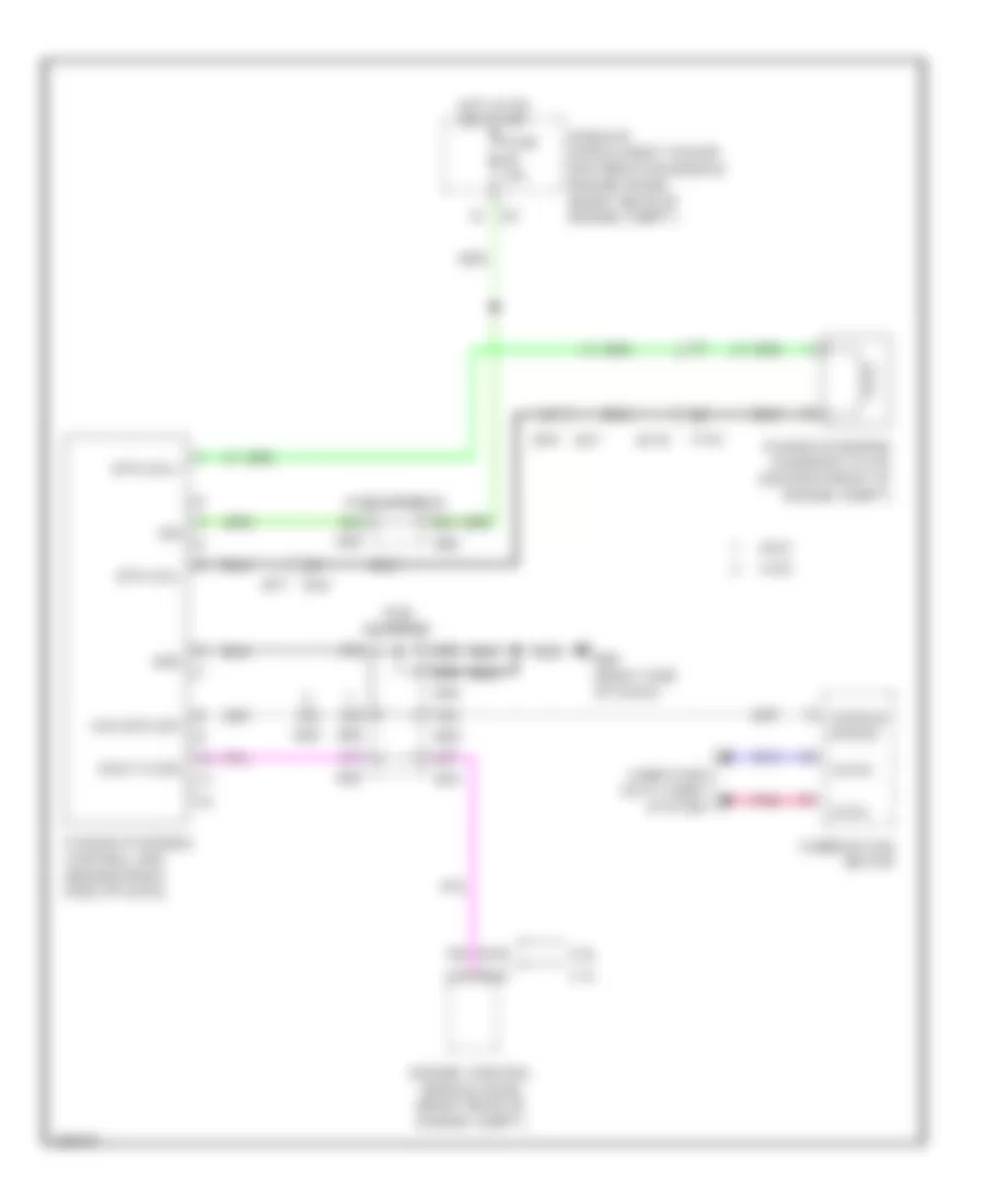
3.5L HYBRID
3.5L Hybrid, Cooling Fan Wiring Diagram for Infiniti Q70 5.6 2014
List of elements for 3.5L Hybrid, Cooling Fan Wiring Diagram for Infiniti Q70 5.6 2014:
- (right side of engine compt) e46
- Comm line
- Computer data lines system
- Cooling fan control module 1 (behind left side of radiator)
- Cooling fan motor 1 (behind right side of radiator)
- Cooling fan motor 2 (behind left side of radiator)
- Cooling fan relay (in fuse, fusible link & relay box)
- Cpu
- E106
- E301
- E302
- E37
- E46 (right side of engine compt)
- Engine control module (ecm) (right end of dash)
- Engine controls system
- Engine coolant
- Engine coolant temperature sensor (rear of left cylinder bank)
- F102
- Fuse & fusible link block (on battery positive post)
- Fuse 10a
- Fusible link g 50a
- Gnd
- Hot at all times
- Ignition relay
- Ipdm e/r (intelligent power distribution module engine room) (right rear of engine compt)
- M107
- M28
- M29
- M30
- Nca
- Pcb harness
- Pnk
- Pwm-pwr
- Pwm-sig
- Red
- Refrigerant pressure sensor
- Refrigerant pressure sensor (right front of engine compt)
- Sensor ground
- Tan
- Temperature sensor
3.5L Hybrid, Hybrid Cooling Fan Wiring Diagram for Infiniti Q70 5.6 2014
List of elements for 3.5L Hybrid, Hybrid Cooling Fan Wiring Diagram for Infiniti Q70 5.6 2014:
- (left "c" pillar) battery cooling fan relay
- B159
- B160
- B224 (right rear of luggage compt)
- B245
- B33
- B64 (left side of rear bumper)
- Battery cooling fan (top of li-ion battery assembly)
- Can h
- Can l
- Computer data lines system
- Electric compressor (left side of engine)
- Fuse & fusible link block 3 (on battery positive post)
- Fuse 10a
- Gnd
- Hot at all times
- Hpcm (behind center of rear seats)
- Ign
- Li-ion battery (under luggage compt floor)
- Li-ion battery controller
- Pnk
- Red
- Shield
3.7L
3.7L, Cooling Fan Wiring Diagram for Infiniti Q70 5.6 2014
List of elements for 3.7L, Cooling Fan Wiring Diagram for Infiniti Q70 5.6 2014:
- (right side of engine compt) e46
- Avcc2 pdpres ftpres
- Battery terminal w/ fusible link
- Can-h1
- Can-l1
- Computer data lines system
- Cooling fan control module (behind radiator)
- Cooling fan motor 1 (behind left side of radiator)
- Cooling fan motor 2 (behind right side of radiator)
- Cooling fan relay 1 (in fuse, fusible link & relay box)
- Cpu
- E106
- E301
- E302
- E37
- E46 (right side of engine compt)
- Ecm (engine control module) (right rear of engine compartment)
- Engine controls system
- Engine coolant temperature sensor (left rear of engine)
- F102
- Fuse 10a
- Fusible link d 80a
- Fusible link holder (righ side of engine compt)
- Fusible link o 50a
- Gnda-o2s-tw -to
- Gnda-pdpres ftpres
- Hot at all times
- Ignition relay
- Ipdm e/r (intelligent power distribution module engine room) (right rear of engine compt)
- M107
- M28
- M29
- M30
- Nca
- Pcb harness
- Pdpres
- Pnk
- Red
- Refrigerant pressure sensor (right front of engine compartment)
- Tan
5.6L
5.6L, Cooling Fan Wiring Diagram for Infiniti Q70 5.6 2014
List of elements for 5.6L, Cooling Fan Wiring Diagram for Infiniti Q70 5.6 2014:
- Battery terminal w/ fusible link
- Can comm line
- Computer data lines system
- Cooling fan control module 1 (behind left side of radiator)
- Cooling fan control module 2 (behind right side of radiator)
- Cooling fan motor 1 (behind left side of radiator)
- Cooling fan motor 2 (behind right side of radiator)
- Cooling fan relay 1 (in fuse, fusible link & relay box)
- Cooling fan relay 2 (in fusible link holder)
- Cpu
- E106
- E301
- E303
- E37
- E39
- E46 (right side of engine compt)
- Engine control module (ecm) (right rear of engine compt)
- Engine controls system
- Engine coolant
- Engine coolant temperature sensor (right rear of engine)
- F110
- Fuse 10a
- Fusible link d 80a
- Fusible link holder
- Fusible link o 50a
- Fusible link r 50a
- Hot at all times
- Ignition relay
- Ipdm e/r (intelligent power distribution module engine room) (right rear of engine compt)
- M160
- M28
- M29
- M30
- Nca
- Pcb harness
- Pnk
- Red
- Refrigerant pressure sensor
- Refrigerant pressure sensor (right front of engine compt)
- Sensor ground
- Tan
- Temperature sensor
CRUISE CONTROL
Cruise Control Wiring Diagram, Except Hybrid (1 of 2) for Infiniti Q70 5.6 2014
List of elements for Cruise Control Wiring Diagram, Except Hybrid (1 of 2) for Infiniti Q70 5.6 2014:
- (or pnk)
- (or red)
- 12c
- 3.7l
- 5.6l
- Accelerator pedal position sensor (on accelerator pedal bracket)
- Aps1
- Aps2
- Ascd brake switch (on brake pedal bracket)
- Ascd brk sw
- Ascd steering switch
- Cancel switch
- Combination switch (spiral cable)
- Computer data lines system
- E103
- E106 m6
- E20
- Ecm (engine control module) (right rear of engine compt)
- F101
- F102
- F111
- F40
- Fuse 10a
- Fuse 15a
- Fuse block (j/b) (behind left end of dash)
- Hot at all times
- Hot in on or start
- Ipdm e/r (intelligent power distribution module engine room) (right rear of engine compt)
- M107
- M160
- M2 3b
- M24
- M303
- M36
- M6 e106
- Main (on/ off) switch
- Motor1-b1
- Motor2-b1
- Motrlyi-b1
- Mtr pwr sply
- Mtr rly
- Nca
- Pcb harness
- Pnk
- Pwr sply
- Red
- Resume/ accelerate switch
- Sens gnd
- Sens pwr sply
- Sensor 1
- Sensor 2
- Set/ coast switch
- Stop lamp switch (on brake pedal bracket)
- Stop lp sw
- Tan
- Throttle control motor relay
- Throttle ctrl- mtr (bank 2) (close)
- Throttle ctrl- mtr (bank 2) (open)
- Tps1-b1
- Tps1-b2
- Tps2-b1
- Tps2-b2
- Vehcan-h1 can comm ascd steering sw gnda-ascdsw sens gnd
- Vehcan-l1 can comm
- Vmot-b1
Cruise Control Wiring Diagram, Except Hybrid (2 of 2) for Infiniti Q70 5.6 2014
List of elements for Cruise Control Wiring Diagram, Except Hybrid (2 of 2) for Infiniti Q70 5.6 2014:
- (3.7l) (right side of dash)
- (or pnk)
- (or red)
- 3.7l
- 5.6l
- A/t assembly
- Can-h
- Can-l
- Close
- Combination meter
- Computer data lines system
- Cruise ind (lcd) & set ind
- Electric throttle control actuator (bank 1) (3.7l: right throttle body) (5.6l: left throttle body)
- Electric throttle control actuator (bank 2) (3.7l: left throttle body) (5.6l: right throttle body)
- Gnd
- Ign sig
- Input speed sensor 1
- Input speed sensor 2
- Joint connector
- M11 (left side of dash)
- M95 m55 (5.6l) (lower right center of dash)
- Nca
- Open
- Output speed sensor
- Pnk
- Sensor 1
- Sensor 2
- Shield
- Tan
- Tcm (transmission control module)
- Throttle control motor
- Throttle position sensor
- Transmission range switch
Cruise Control Wiring Diagram, Hybrid (1 of 2) for Infiniti Q70 5.6 2014
List of elements for Cruise Control Wiring Diagram, Hybrid (1 of 2) for Infiniti Q70 5.6 2014:
- Accelerator pedal position (app) sensor (on accelerator pedal bracket)
- App sens 1
- App sens 2
- Ascd steering switch
- Ascd str sw
- B158
- B159
- B24 (left rear quarterpanel)
- B37
- B44
- Can-h
- Can-l
- Cancel switch
- Combination switch (spiral cable) (top of steering column)
- Computer data lines system
- E103 8f
- E106
- E106 m6
- E19
- Ecm (engine control module) (right end of dash)
- F101
- F102
- Fuse 10a
- Fuse 15a
- Fuse block (j/b) (behind left end of dash)
- Hot at all times
- Hpcm (behind center of rear seats)
- Ipdm e/r (intelligent power distribution module engine room) (right rear of engine compt)
- M107
- M2 3b
- M303
- M36
- M77
- Main (on/off) switch
- Motor close-b1
- Motor close-b2
- Motor open-b1
- Motor open-b2
- Motrly
- Mtr pwr sply
- Nca
- Pnk
- Pwr sply
- Red
- Resume/ accelerate switch
- Sens gnd
- Sens pwr sply
- Sensor gnd
- Set/ coast switch
- Shield
- Stop lamp switch (on brake pedal bracket)
- Stop lp sw
- Stp lmp sw
- Throttle control motor relay
- Tps1-b1
- Tps1-b2
- Tps2-b1
- Tps2-b2
- Vmot-b1
Cruise Control Wiring Diagram, Hybrid (2 of 2) for Infiniti Q70 5.6 2014
List of elements for Cruise Control Wiring Diagram, Hybrid (2 of 2) for Infiniti Q70 5.6 2014:
- A/t assembly
- Can-h
- Can-l
- Close
- Combination meter
- Computer data lines system
- Cruise (lcd) & set ind
- Electric throttle control actuator (bank 1) (right throttle body)
- Electric throttle control actuator (bank 2) (left throttle body)
- Gnd
- Input speed sensor 1
- Input speed sensor 2
- Joint connector
- M11 (left side of dash)
- M95 (right side of dash)
- Nca
- Open
- Output speed sensor
- Pnk
- Red
- Sensor 1
- Sensor 2
- Shield
- Tcm (transmission control module)
- Throttle control motor
- Throttle position sensor
- Transmission range switch
Intelligent Cruise Control Wiring Diagram, Except Hybrid for Infiniti Q70 5.6 2014
List of elements for Intelligent Cruise Control Wiring Diagram, Except Hybrid for Infiniti Q70 5.6 2014:
- (left rear of engine compt) e22
- (right side of dash) m95
- 10a
- 3.7l
- 5.6l
- A/t assembly
- Accelerator pedal actuator (above accelerator pedal bracket)
- Accelerator pedal position (app) sensor (on accelerator pedal bracket)
- Adas control unit (rear of vehicle)
- Anti-lock brakes system
- Aps1
- Aps2
- Ascd brk sw
- Ascd sw
- B24 (left rear quarter panel)
- Bat
- Brake hold rly drv sig
- Can comm
- Can-h
- Can-l
- Cancel switch
- Combination meter
- Combination switch (spiral cable)
- Comm-h
- Comm-l
- Computer
- Computer data lines system
- Cruise ind & speed limit ind
- Data lines
- Distance switch
- Dynamic driver assistance switch
- E103
- E106
- Ecm (engine control module) (right rear of engine compt)
- Fuse & fusible link holder (right rear of engine compt)
- Fuse 3 10a
- Fuse 46
- Fuse 63
- Fuse 7 10a
- Fuse block j/b (behind left end of dash)
- Gnd
- Gnd ascd sw sens gnd
- Hot at all times
- Hot in on or start
- Iba off sw
- Iba off switch
- Icc brake hold relay (in fuse, fusible link & relay box)
- Icc brake switch (on brake pedal bracket)
- Icc sensor (left side of front bumper)
- Icc steering switch
- Ign
- Input speed sensor 1
- Input speed sensor 2
- Interior lights system
- Ipdm e/r (intelligent power distribution module engine room) (right rear of engine compt)
- Its comm-h
- Its comm-l
- Joint connector
- M105
- M107
- M11 (left side of dash)
- M150
- M150 m151
- M151
- M160
- M181
- M20
- M23
- M27
- M30
- M303
- M36
- Main on/off switch
- Navigation system
- Nca
- On ind
- Output speed sensor
- Pcb harness
- Pnk
- Red
- Resistor
- Resume/accel switch
- Sens gnd
- Sens pwr sply
- Sensor 1
- Sensor 2
- Set/coast switch
- Shield
- Stop lamp switch (on brake pedal bracket)
- Stp lp sw
- System
- Tan
- Tcm (transmission control module)
- Transmission range switch
- Warning buzzer
- Warning system sw
Intelligent Cruise Control Wiring Diagram, Hybrid (1 of 2) for Infiniti Q70 5.6 2014
List of elements for Intelligent Cruise Control Wiring Diagram, Hybrid (1 of 2) for Infiniti Q70 5.6 2014:
- (left rear quarterpanel) b24
- 10a
- Accelerator pedal actuator (above accelerator pedal bracket)
- Adas control unit (underside of rear cargo self)
- B222
- B69
- Batt
- Brake hold rly drv sig
- Can-h
- Can-l
- Cancel switch
- Combination meter
- Combination switch (spiral cable) (top of steering column)
- Comm-h
- Comm-l
- Computer data lines system
- Cruise, ldp & speed limit ind
- Distance switch
- Dynamic driver assistance switch
- E103
- E106
- E119
- Exterior lights system
- Fuse & fusible link block (on battery positive post)
- Fuse 1
- Fuse 10a
- Fuse 3
- Fuse 7 10a
- Fuse block (j/b) (behind left end of dash)
- Gnd
- Hot at all times
- Hot in on or start
- Iba off sw
- Iba off switch
- Icc steering switch
- Ign
- Interior lights system
- Ipdm e/r (intelligent power distribution module engine room) (right rear of engine compt)
- Its comm-h
- Its comm-l
- M11 (left side of dash)
- M150
- M151
- M181 m105
- M20
- M23
- M303
- M36
- Main on/off switch
- Navigation system
- Nca
- Pcb harness
- Pnk
- Red
- Resume/accel switch
- Set/coast switch
- Tan
- Warning buzzer
- Warning sys on ind
- Warning sys sw
Intelligent Cruise Control Wiring Diagram, Hybrid (2 of 2) for Infiniti Q70 5.6 2014
List of elements for Intelligent Cruise Control Wiring Diagram, Hybrid (2 of 2) for Infiniti Q70 5.6 2014:
- (at high stop lamp assembly) icc brake hold relay
- (at high stop lamp assembly) stop lamp off relay 1
- (left rear of engine compt) abs actuator & electric unit
- (on brake pedal bracket) stop lamp switch
- A/t assembly
- Acc str sw
- Accelerator pedal position (app) sensor (on accelerator pedal bracket)
- App sens 1
- App sens 2
- Aps 1
- Aps 2
- B158
- B159
- B228
- B24 (left rear quarterpanel)
- B28
- B37
- B44
- B69
- Brake switch (on brake pedal bracket)
- Brk sw
- Can-h
- Can-l
- Comm-h
- Comm-l
- Computer data lines system
- E106
- E119
- E19
- E22 (left rear of engine compt)
- Exterior lights system
- Gnd
- Hpcm (behind center of rear seats)
- Icc sensor
- Ignition
- Input speed sensor 1
- Input speed sensor 2
- Joint connector
- M150
- M151
- M27
- M30
- M77
- M95 (right side of dash)
- Nca
- Output speed sensor
- Pcb harness
- Pnk
- Red
- Resistor
- Sens gnd
- Sens pwr sply
- Sensor gnd
- Shield
- Stp lmp sw
- Tcm (transmission control module)
- Transmission range switch
DEFOGGERS
Defoggers Wiring Diagram, Except Hybrid for Infiniti Q70 5.6 2014
List of elements for Defoggers Wiring Diagram, Except Hybrid for Infiniti Q70 5.6 2014:
- 10c
- 11g
- Av comm (h)
- Av comm (l)
- Av control unit (behind center of dash)
- B201
- B202 (right kick panel)
- B204
- B471
- B472
- B473
- B6 10g
- Bat (f/l)
- Bat (fuse)
- Bcm (body control module) (behind left side of dash)
- Can-h
- Can-l
- Computer data lines system
- Condenser (left "c" pillar)
- D31
- Driver side door mirror (door mirror defogger)
- E101
- Fuse & fusible link block (right rear of engine compt)
- Fuse 10a
- Fuse 20a
- Fuse block (j/b) (behind left end of dash)
- Fusible link e 100a
- Fusible link holder (righ side of engine compt)
- Fusible link l 40a
- Gnd
- Hot at all times
- Hot in on or start
- M11 (left side of dash)
- M117
- M120
- M122
- M2 4b
- M210
- M3 9c
- M84
- Multi-function switch (rear window defogger switch)
- Nca
- Passenger's side door mirror (door dirror defogger)
- Pnk
- Rear window defogger
- Rear window defogger relay
- Red
- Rr window defg rly m120
- W/ navigation
- W/o navigation
Defoggers Wiring Diagram, Hybrid for Infiniti Q70 5.6 2014
List of elements for Defoggers Wiring Diagram, Hybrid for Infiniti Q70 5.6 2014:
- 10c
- 11g
- Av comm (h)
- Av comm (l)
- Av control unit (behind center of dash)
- B201
- B202
- B204
- B471
- B472
- B473
- B6 10g
- Bat (f/l)
- Bat (fuse)
- Bcm (body control module) (under left side of dash)
- Can-h
- Can-l
- Computer data lines system
- Condenser (top of engine)
- D31
- Driver side door mirror (door mirror defogger)
- E101
- Fuse & fusible link block (on battery positive post)
- Fuse 10a
- Fuse 20a
- Fuse block (j/b) (behind left end of dash)
- Fuse link r 100a
- Fusible link block
- Fusible link l 40a
- Gnd
- Hot at all times
- Hot in on or start
- M11 (left side of dash)
- M117
- M120
- M122
- M2 4b
- M210
- M3 9c
- M84
- Multi-function switch (rear window defogger switch)
- Nca
- Passenger side door mirror (door mirror defogger)
- Pnk
- Rear window def rly cont m120
- Rear window defogger
- Rear window defogger relay
- Red
- W/ navigation
- W/o navigation
ELECTRONIC POWER STEERING
Electronic Power Steering Wiring Diagram, Except Hybrid with 4WAS for Infiniti Q70 5.6 2014
List of elements for Electronic Power Steering Wiring Diagram, Except Hybrid with 4WAS for Infiniti Q70 5.6 2014:
- 12c
- 4was
- 4was comm-h
- 4was comm-l
- 4was front actuator
- 4was front control unit (right end of dash)
- 4was main control unit (left rear of luggage compt)
- 4was rear motor (under center rear of vehicle)
- 4was rear motor relay (left side of luggage compt)
- B14
- B44
- B61 (left side of rear bumper)
- Bat pwr sply
- Can-h
- Can-l
- Combination meter
- Computer data lines system
- E103
- E105
- E106
- Eps sol
- Exterior lights system
- F-mtr (v)
- F103
- Fr-ang sen sig (cos)
- Fr-ang sen sig (excitation)
- Fr-ang sen sig (sin)
- Fr-angl sen gnd
- Fr-mtr (u)
- Fr-mtr (w)
- Fr-mtr gnd
- Fr-mtr pwr sply
- Fuse & fusible link block (right rear of engine compt)
- Fuse 10a
- Fuse 20a
- Fuse block (j/b) (behind left end of dash)
- Fusible link holder (right side of engine compt)
- Fusible link q 40a
- Gnd
- Hot at all times
- Hot in on or start
- Ign
- Ign sig
- Ipdm e/r (intelligent power distribution module engine room) (right rear of engine compt)
- Lock sol gnd
- Lock sol pwr sply
- M11 (left side of dash)
- M116
- M12
- M28
- M29
- M30
- M300
- M41
- M42
- M55 (lower right center of dash)
- M77
- M95 (right side of dash)
- Pcb harness
- Pcb harness m24
- Pnk
- Power steering solenoid valve (center front of engine compt)
- R-ang sen sig (sub)
- Rear wheel steering angle sensor (under center rear of vehicle)
- Red
- Rr-ang sen gnd
- Rr-ang sen sig (main) rr-ang sen sig pwr sply
- Rr-mtr (lh)
- Rr-mtr (rh)
- Rr-mtr gnd
- Rr-mtr pwr sply
- Rr-mtr rly
- Stop lp sw
- Tan
Electronic Power Steering Wiring Diagram, Except Hybrid without 4WAS for Infiniti Q70 5.6 2014
List of elements for Electronic Power Steering Wiring Diagram, Except Hybrid without 4WAS for Infiniti Q70 5.6 2014:
- 2wd
- 3.7l
- 5.6l
- Awd
- B44 m77
- Can-h
- Can-l
- Combination meter
- Computer data lines system
- Eng tacho
- Engine control module (ecm) (right rear of engine compt)
- Eps sol+
- Eps sol-
- F103
- Fuse 10a
- Gnd
- Hot in on or start
- Ign
- Ipdm e/r (intelligent power distribution module engine room) (right rear of engine compt)
- M107
- M116
- M160
- M28
- M29
- M30
- M77 b44
- M95 (right side of dash)
- Pcb harness
- Pnk
- Power steering control unit (behind right side of dash)
- Power steering solenoid valve (center front of engine compt)
- Veh spd (2p)
- Vehicle speed
Electronic Power Steering Wiring Diagram, Hybrid for Infiniti Q70 5.6 2014
List of elements for Electronic Power Steering Wiring Diagram, Hybrid for Infiniti Q70 5.6 2014:
- 4f e103
- Batt
- Can-h
- Can-l
- Computer data lines system
- E93 (right side of engine compt)
- E97
- E98
- F-c-valve-h
- F-c-valve-l
- Flow connection valve (on power steering rack)
- Fuse & fusible link block (on battery positive post)
- Fuse 10a
- Fuse block (j/b) (behind left end of dash)
- Fusible link o 80a
- Gnd
- Hot at all times
- Hot in on or start
- Ign
- Pnk
- Power steering control module (right front of engine compt)
- Red
- Shield
- Torque sensor (base of steering column)
- Trq-gnd
- Trq-main
- Trq-sub
- Trq-vcc 1
- Trq-vcc 2
ENGINE PERFORMANCE
3.5L HYBRID
3.5L Hybrid, Engine Controls Wiring Diagram (1 of 5) for Infiniti Q70 5.6 2014
List of elements for 3.5L Hybrid, Engine Controls Wiring Diagram (1 of 5) for Infiniti Q70 5.6 2014:
- (front of engine) f34
- (front of right cylinder bank)
- (or red)
- (top of engine) condenser
- (top of left cylinder bank) ignition coil 2 (w/ power transistor)
- (top of left cylinder bank) ignition coil 4 (w/ power transistor)
- (top of left cylinder bank) ignition coil 6 (w/ power transistor)
- (top of right cylinder bank) ignition coil 1 (w/ power transistor)
- (top of right cylinder bank) ignition coil 3 (w/ power transistor)
- (top of right cylinder bank) ignition coil 5 (w/ power transistor)
- A/f sens1
- A/f-1
- Afh1
- Afh2
- Can-h
- Can-l
- Close
- Computer data lines system
- E phase 2
- E pos sens 1
- Ecm (engine control module) (right end of dash)
- Ecm gnd
- Electric throttle control actuator (bank 2) (left throttle body)
- Evap
- Evtc valve 1
- Evtc valve 2
- Exhaust valve timing control solenoid valve (bank 1) (front of right cylinder bank)
- Exhaust valve timing control solenoid valve (bank 2) (front of left cylinder bank)
- F101
- F102
- F103
- Fpr
- Gnd pos
- Ign 1
- Ign 2
- Ign 3
- Ign 4
- Ign 5
- Ign 6
- Ignsw
- Intake valve timing control solenoid valve (bank 1)
- Intake valve timing control solenoid valve (bank 2)
- Ivtc 1
- Ivtc 2
- M116
- M95 (right side of dash)
- Map sens
- Motor (close) 1
- Motor (open) 1
- Motor2 (close)
- Motor2 (open)
- Motrly
- Nca
- O2hr1
- O2hr2
- Open
- Phase 1
- Phase 2
- Plug spark
- Pnk
- Pos
- Pow sup sen2
- Pss phase 1
- Red
- Sens gnd
- Sens pwr bcs
- Sens pwr sply
- Sens pwr tps 1
- Sens pwr tps 2
- Sensor 1
- Sensor 2
- Snsr gnd
- Spark plug
- Ssoff
- Throttle control motor
- Throttle position sensor
- Tps1 1
- Tps1 2
- Tps2 1
- Tps2 2
3.5L Hybrid, Engine Controls Wiring Diagram (2 of 5) for Infiniti Q70 5.6 2014
List of elements for 3.5L Hybrid, Engine Controls Wiring Diagram (2 of 5) for Infiniti Q70 5.6 2014:
- (or red)
- A/t assembly
- B37
- Can h
- Can l
- Close
- Computer data lines system
- Cpu
- Crankshaft position sensor (right rear of engine)
- E105
- E106
- E19
- E3 f1
- E46 (right side of engine compt)
- Ecm relay
- Electric throttle control actuator (bank 1) (right throttle body)
- Evap canister purge volume control solenoid valve (top right rear of engine)
- F103
- Fuel pump relay
- Fuse 10a
- Fuse 15a
- Hot at all times
- Ignition relay
- Ipdm e/r (intelligent power distribution module engine room) (right rear of engine compt)
- Joint connector
- M116
- Nca
- Open
- Pnk
- Red
- Sensor 1
- Sensor 2
- Tcm (transmission control module)
- Throttle control motor
- Throttle control motor relay
- Throttle position sensor
3.5L Hybrid, Engine Controls Wiring Diagram (3 of 5) for Infiniti Q70 5.6 2014
List of elements for 3.5L Hybrid, Engine Controls Wiring Diagram (3 of 5) for Infiniti Q70 5.6 2014:
- (1, 3 & 5: top of right cylinder bank) (2, 4 & 6: top left cylinder bank) fuel injectors
- (in fuel tank) fuel level sensor unit & fuel pump (main)
- (left air intake tube) mass air flow sensor (bank 2)
- (rear of right cylinder bank) exhaust valve timing control position sensor (bank 1)
- Air fuel ratio (a/f) sensor 1 (bank 1) (right exhaust manifold)
- Air fuel ratio (a/f) sensor 1 (bank 2) (left exhaust manifold)
- B201
- B224 (right rear of luggage compt)
- B230
- B51
- Camshaft position sensor (bank 2) (rear of left cylinder bank)
- Can-h
- Can-l
- Cluster system
- Combination meter
- Computer data lines system
- Engine coolant temperature sensor (rear of left cylinder bank)
- Engine oil temperature sensor (lower right front of engine)
- Exhaust valve timing control position sensor (bank 2) (rear of left cylinder bank)
- F1 e3
- Fuel pump
- Fuel tank temperature sensor
- Gnd fuel sens
- Ground
- Heated oxygen sensor 2 (bank 1) (on right three way catalyst)
- Heated oxygen sensor 2 (bank 2) (on left three way catalyst)
- Instrument
- M11 (left side of dash)
- M117
- Malfunction ind lamp
- Nca
- Pnk
- Red
3.5L Hybrid, Engine Controls Wiring Diagram (4 of 5) for Infiniti Q70 5.6 2014
List of elements for 3.5L Hybrid, Engine Controls Wiring Diagram (4 of 5) for Infiniti Q70 5.6 2014:
- (left rear of luggage compt) c4
- (or red)
- B151
- B152
- B153
- B154
- B163
- B27
- B64 (left side of rear bumper)
- Battery current sensor (near battery)
- Battery terminal w/ fusible link
- C21
- Camshaft position sensor (bank 1) (rear of right cylinder bank)
- Can-h
- Can-l
- Computer data lines system
- E106
- Evap control system pressure sensor (under center rear of vehicle)
- F103
- Fusible link f 50a
- Gnd
- Hot at all times
- M116
- M12 b14
- M28
- M29
- M30
- Nca
- Pcb harness
- Pnk
- Pow sup (bat)
- Pow sup (ign)
- Pump relay
- Red
- Refrigerant pressure sensor (right front of engine compt)
- Sub electric oil pump (left rear of engine)
- Sub electric oil pump inverter
- Sub electric oil pump relay
- Tan
- U-phase
- V-phase
- W-phase
3.5L Hybrid, Engine Controls Wiring Diagram (5 of 5) for Infiniti Q70 5.6 2014
List of elements for 3.5L Hybrid, Engine Controls Wiring Diagram (5 of 5) for Infiniti Q70 5.6 2014:
- (on brake pedal bracket) stop lamp switch
- (right air intake tube) mass air flow sensor (bank 1)
- A/f sens 2
- Active noise control unit (w/o bose system) (left front of luggage compt)
- Avcc ftprs
- B44
- Batt cur sen
- Bose amp (w/ bose system) (left front of luggage compt)
- Brk sw
- Can
- Communition line
- Computer data lines system
- Cruise control system
- Dlc
- E103
- E115
- Ecm (engine control module) (right end of dash)
- Ecm gnd
- Egn spd o/p sig
- Eng oil pr sens
- Engine oil pressure sensor (lower right front of engine)
- Evap canister vent control valve (on evap canister)
- Evap ctrl
- Evap sens
- F102
- F103
- F201 f9
- Fuel tnk ts
- Fuse 10a
- Fuse block (j/b) (behind left end of dash)
- Gnd
- Gnd (pha sen)
- Gnd o2 sens 2
- Hot at all times
- Inj 1
- Inj 2
- Inj 3
- Inj 4
- Inj 5
- Inj 6
- Knk1
- Knk2
- Knock sensor (bank 1) (top center of right cylinder bank)
- Knock sensor (bank 2) (top center of left cylinder bank)
- M107
- M116
- M77
- M95 (right side of dash)
- Manifold absolute pressure (map) sensor (left rear of intake manifold)
- Map sen
- Mass af sens1
- Mass af sens2
- O2sr2
- Pnk
- Pwr sply
- Red
- Ref pre sens
- Sens gnd
- Shield
- Sps (maf san)
- Stp lp sw
- Ta1
- Tacho
- Tan
- Temp sens
3.5L Hybrid, Hybrid System Wiring Diagram (1 of 4) for Infiniti Q70 5.6 2014
List of elements for 3.5L Hybrid, Hybrid System Wiring Diagram (1 of 4) for Infiniti Q70 5.6 2014:
- Accelerator pedal position (app) sensor (on accelerator pedal bracket)
- App sens 1
- App sens 2
- Ascd/acc str sw
- B158
- B24 (left rear quarterpanel)
- B37
- B44
- B61 (left side of rear bumper)
- B69
- Batt vol
- Battery cooling fan relay (left "c" pillar)
- Clutch 1 stroke sens
- Dc/dc con act sig
- Dc/dc con volt
- Dc/dc sig
- E106 m6
- E119
- E19
- Fuse & fusible link block 3 (on battery positive post)
- Fuse 10a
- Fuse 20a
- Fusible link y 50a
- Hot at all times
- Hpcm (behind center of rear seats)
- Hpcm gnd
- Ign sig
- M150
- M151
- M77
- Nca
- Pnk
- Pwr sply from hpcm
- Red
- Self shut off relay
- Self shut off rly
- Sens gnd
- Sens gng
- Sens pwr sply
- Sensor gnd
- Shield
- Stabilizer sig
- Sys main rly 1
- Sys main rly 2
- W/ intelligent cruise control
- W/o intelligent cruise control
3.5L Hybrid, Hybrid System Wiring Diagram (2 of 4) for Infiniti Q70 5.6 2014
List of elements for 3.5L Hybrid, Hybrid System Wiring Diagram (2 of 4) for Infiniti Q70 5.6 2014:
- (+)
- (-)
- B24 (left rear quarterpanel)
- B37
- B44 m77
- Batt
- C16
- C17
- Can-h
- Can-l
- Cl1 strk
- Computer data lines system
- Detection connection
- E106
- E19
- E46 (right side of engine compt)
- E78
- F77
- Fuse 10a
- Gnd
- Gnd a
- Hot in on or start
- Ipdm e/r (intelligent power distribution module engine room (right rear of engine compt)
- Nca
- Pnk
- Power sply
- R2 rez (+)
- Red
- Resolver sig r1 traction mtr
- Resolver sig r2 traction mtr
- Resolver sig s1 traction mtr
- Resolver sig s2 traction mtr
- Resolver sig s3 traction mtr
- Resolver sig s4 traction mtr
- Rez (+)
- Rez s1
- Rez s2
- Rez s3
- Rez s4
- Sens gnd
- Shield
- Temp snsr traction mtr
- Tm gnd
- Traction motor (rear of engine)
- Traction motor inverter (right rear of engine compt)
- U-phase
- V-phase
- W-phase
3.5L Hybrid, Hybrid System Wiring Diagram (3 of 4) for Infiniti Q70 5.6 2014
List of elements for 3.5L Hybrid, Hybrid System Wiring Diagram (3 of 4) for Infiniti Q70 5.6 2014:
- (at high stop lamp assembly) (w/ intelligent cruise control) stop lamp off relay 2
- (on brake pedal bracket) brake switch
- (on brake pedal bracket) stop lamp switch
- (right rear of luggage compt) b224
- A/t assembly
- Anti-lock brakes system
- B159
- B201
- B228
- B24 (left rear quarterpanel)
- B28
- B37
- B44
- B5 b222
- Body control module (under left side of dash)
- Brake sw
- Can-h
- Can-l
- Computer data lines system
- Cruise control system
- E103
- E119 b69
- E19
- E19 b37
- E46 (right side of engine compt)
- Electric water pump (left front of engine compt)
- Eltc water pump
- Exterior lights system
- F103
- Fuse 10a
- Fuse block (j/b) (behind left end of dash)
- Hev sys can-h
- Hev sys can-l
- Hot at all times
- Hot in on or start
- Hpcm (behind center of rear seats)
- Inter lock sw sig
- Joint connector
- M116
- M117
- M77
- Pnk
- Ready sig
- Red
- Service plug
- Shield
- Shift interlock system
- Start rly cont
- Stop lamp off relay 1 (w/ intelligent cruise control) (at high stop lamp assembly)
- Stop lamp sw
- Tcm (transmission module) control
- Trans range sw
- W/ intelligent cruise control
- W/o intelligent cruise control
3.5L Hybrid, Hybrid System Wiring Diagram (4 of 4) for Infiniti Q70 5.6 2014
List of elements for 3.5L Hybrid, Hybrid System Wiring Diagram (4 of 4) for Infiniti Q70 5.6 2014:
- (top of li-ion battery assembly) cooling fan battery
- Activate sig
- Air con seat rly
- Assistance switch
- B160
- B224 (right rear of luggage compt)
- B245
- B301
- B304
- B33
- B460
- B461
- B64 (left side of rear bumper)
- Battery terminal w/ fusible link
- C13
- Cancel switch
- Coast switch
- Colling mode req sig
- Combination switch (spiral cable) (top of steering column)
- Computer data lines system
- Dc/dc converter
- Distance switch
- Dynamic driver
- Electric compressor (left side of engine)
- Fusible link a 250a
- Gnd
- Hi volt (+)
- Hi volt (-)
- Hi volt for precharge (+)
- Hot at all times
- Icc steering switch
- Ign
- Junction box
- Li-ion battery (under luggage compt floor)
- Li-ion battery controller
- M303
- M36
- Main
- Nca
- On/off switch
- Pnk
- Pre charge sig
- Pwr sply
- Red
- Resume/ accelerate switch
- Resume/accel switch
- Seats system
- Set/
- Shield
- Switch off) (on/
- Switch set/coast
- Volt stablizer sig
- W/ intelligent cruise control
- W/o intelligent cruise control
3.7L
3.7L, Engine Performance Wiring Diagram (1 of 6) for Infiniti Q70 5.6 2014
List of elements for 3.7L, Engine Performance Wiring Diagram (1 of 6) for Infiniti Q70 5.6 2014:
- (bank 2) (close)
- (front of engine compt)
- (ignition coils 1, 3 & 5: top right of engine) (ignition coils 2, 4 & 6: top left of engine)
- (rear of engine)
- Af+1
- Af-1
- Afh1
- Afh2
- Avcc phs1-e phs1/ps
- Avcc pos
- Camshaft position sens (bank 1)
- Camshaft position sens (bank 2)
- Camshaft position sensor (phase) (bank 1) (right front of engine)
- Computer data lines system
- Crankshaft position sens
- Crankshaft position sensor (pos)
- E20
- Ecm (engine control module) (right rear of engine compt)
- Ecm gnd
- Evap
- F101
- F102
- F103
- F34 (front of engine)
- F40
- Fpr
- Gnd pos
- Gnda-tps-b2
- Ign 1
- Ign 2
- Ign 3
- Ign 4
- Ign 5
- Ign 6
- Ignition coil 1 (w/ power transistor)
- Ignition coil 2 (w/ power transistor)
- Ignition coil 3 (w/ power transistor)
- Ignition coil 4 (w/ power transistor)
- Ignition coil 5 (w/ power transistor)
- Ignition coil 6 (w/ power transistor)
- Intake temperature sensor
- M116
- M116 f103
- M95 (right side of dash)
- Manifold absolute press sens
- Manifold absolute pressure sensor (left rear of engine)
- Mass air flow sensor (bank 1) (right air intake tube)
- Mass air flow sensor (bank 2) (left air intake tube)
- Nca
- O2hr1 intake vlv timing ctrl sol vlv (bank 1)
- O2hr2
- Pnk
- Position sens (bank 2)] sens pwr sply [(throttle position sens (bank 2)]
- Power steering pressure sensor
- Red
- Sens gnd
- Sens pwr sply [(throttle
- Sig (vvel ctrl mod) intake vlv timing ctrl sol vlv (bank 1)
- Spark plug
- Ssoff
- Throttle ctrl mtr
- Throttle ctrl mtr (bank 1) (open) throttle ctrl mtr power sply (bank 1) throttle ctrl mtr (bank 1) (close)
- Throttle ctrl mtr (bank 2) (open)
- Throttle ctrl mtr rly
- Throttle ctrl mtr rly pwr sply (bank 2) ign sw can communication line (vvel ctrl mod) can communication line (vvel ctrl mod)
- Tps1-b1
- Tps1-b2
- Tps2 b2
- Tps2-b1
- Vvel actr mtr rly abort
3.7L, Engine Performance Wiring Diagram (2 of 6) for Infiniti Q70 5.6 2014
List of elements for 3.7L, Engine Performance Wiring Diagram (2 of 6) for Infiniti Q70 5.6 2014:
- B206
- B207
- B224 (right rear quarter panel)
- B51 b230
- Can-h
- Can-l
- Close
- Combination meter
- Computer data lines system
- Cpu
- E105
- E106
- E20
- E46 (right side of engine compt)
- Ecm relay
- Electric throttle control actuator (bank 1) (right throttle body)
- Evap canister purge volume control solenoid valve (top right rear of engine)
- F103
- F120
- F30
- F40
- Fuel level sensor unit & fuel pump (in fuel tank)
- Fuel pump
- Fuel pump relay
- Fuel tank temperature sensor
- Fuse 10a
- Fuse 15a
- Gnd
- Hot at all times
- Hot in on or start
- Ignition relay
- Instrument cluster system
- Ipdm e/r (intelligent power distribution module engine room) (right rear of engine compt)
- Jumping connector (left side of luggage compt)
- M11 (left side of dash)
- M116
- M117 b201
- M95 (right side of dash)
- Malfunction ind
- Nca
- Open
- Pnk
- Red
- Sens gnd
- Sensor 1
- Sensor 2
- Throttle control motor
- Throttle control motor relay
- Throttle position sensor
3.7L, Engine Performance Wiring Diagram (3 of 6) for Infiniti Q70 5.6 2014
List of elements for 3.7L, Engine Performance Wiring Diagram (3 of 6) for Infiniti Q70 5.6 2014:
- (fuel injectors 1, 3 & 5: top right of engine) (fuel injectors 2, 4 & 6: top left of engine)
- (left rear of engine) engine coolant temperature sensor
- (lower right front of engine)
- Close
- Condenser (left "c" pillar)
- E20
- Electric throttle control actuator (bank 2) (left throttle body)
- Engine oil temperature sensor
- F120 f30
- F40
- Fuel injector
- Heated oxygen sensor 2 (bank 1) (left side of engine)
- Heated oxygen sensor 2 (bank 2) (left front of engine)
- Intake valve timing control solenoid valve (bank 1) (right front of engine)
- Intake valve timing control solenoid valve (bank 2) (left front of engine)
- M95 (right side of dash)
- Nca
- Open
- Pnk
- Red
- Sensor 1
- Sensor 2
- Throttle control motor
- Throttle position sensor
3.7L, Engine Performance Wiring Diagram (4 of 6) for Infiniti Q70 5.6 2014
List of elements for 3.7L, Engine Performance Wiring Diagram (4 of 6) for Infiniti Q70 5.6 2014:
- (left front of engine) camshaft position sensor (phase) (bank 2)
- (right rear of engine compt) battery current sensor
- (top of engine) knock sensor (bank 1)
- (top of engine) knock sensor (bank 2)
- (under rear of vehicle) evap canister vent control valve
- Accelerator pedal position (app) sensor (above accelerator pedal bracket)
- Air fuel ratio (a/f) sensor 1 (bank 1) (right side of engine)
- Air fuel ratio (a/f) sensor 1 (bank 2) (left side of engine)
- B71
- B71 b72
- B72
- B8 e115
- E106
- E20
- Evap control system pressure sensor (under right rear of vehicle)
- F201
- F40
- M150 m151
- M23
- M28
- M29
- M30
- M95 (right side of dash)
- Nca
- Pcb harness
- Pnk
- Red
- Refrigerant pressure sensor (right front of engine compt)
- Sensor 1
- Sensor 2
- Shield
- Tan
3.7L, Engine Performance Wiring Diagram (5 of 6) for Infiniti Q70 5.6 2014
List of elements for 3.7L, Engine Performance Wiring Diagram (5 of 6) for Infiniti Q70 5.6 2014:
- A/f sens 1 (bank 2)
- A/f sens 1 (bank 2) intake air temp sens (bank 1) gnda qa1/ta1
- A/t assembly
- Accelerator pedal position (app) sensor (on accelerator pedal bracket)
- Aps1
- Aps2 sens pwr sply (accelerator pdl position sens 1) sens gnd(accelerator position sens 1) ascd sw ftpres
- Ascd brk sw
- Avcc phs2-e phs2/cu
- Avcc2 pdpres/ftpres
- Avcc2-aps2
- B71 b72
- Batt temp
- Can-h
- Can-l
- Computer data lines system
- Cruise control system
- Cursen
- Data link connector
- E103
- E106
- E20 f40
- Ecm (engine control module) (right rear of engine compt)
- Ecm gnd
- Electronic power steering system
- Eng coolant temp sens gnda-knk
- Eng spd sig out
- Evap canister vent ctrl vlv
- F102
- F40 e20
- Fuse 10a
- Fuse block (j/b) (behind left end of dash)
- Gnd ascd sw
- Gnda cursen
- Gnda pdpres/ftpres can communication line can communication line
- Gnda phs 1/ps
- Gnda, phs 2 pwr sply for ecm (back-up) gnda qa2
- Hot in on or start
- Icc brake switch (w/ icc) ascd brake switch (w/o icc) (on brake pedal bracket)
- Ing 6
- Inj 1
- Inj 3
- Inj 4
- Joint connector
- Knk1
- Knk2
- M107
- M20
- M30
- M6 e106
- M95 (right side of dash)
- Nca
- O2sr1 mass air flow sens (bank 1) eng oil temp sens mass air flow sens (bank 2) o2sr2
- Pcb harness
- Pnk
- Pspres
- Pwr sply for ecm
- Red
- Sens gnd
- Sens gnd (with icc) refrigerant press sens fuel tank temp sens
- Sensor 1
- Sensor 2
- Shield
- Start rly
- Starting/ charging system
- Stop lamp sw
- Tan
- Tcm (transmission control module)
- Trans rng sw
- W/ icc
- W/o icc
3.7L, Engine Performance Wiring Diagram (6 of 6) for Infiniti Q70 5.6 2014
List of elements for 3.7L, Engine Performance Wiring Diagram (6 of 6) for Infiniti Q70 5.6 2014:
- (top rear of left cylinder head)
- Abort
- Agnd 1
- Agnd 2
- Agnd 3
- Agnd 4
- Avcc1
- Avcc2
- Avcc3
- Avcc4
- Can l
- Computer data lines system
- E20
- E22 (left rear of engine compt)
- E46 (right side of engine compt)
- Eng communication line
- F40
- Fuse & fusible link block (right rear of engine compt)
- Fusible link g 50a
- High lift
- Hot at all times
- Low lift
- M-rly
- Motor 2-b2
- Motor-b1
- Motor1-b2
- Motor2-b1
- P-gnd
- Pnk
- Red
- Sensor 1
- Sensor 2
- Shield
- Vel/s1-b1
- Vel/s1-b2
- Vel/s2-b1
- Vel/s2-b2
- Vmot-b1
- Vmot-b2
- Vvel actuator motor (bank 1) (rear of engine)
- Vvel actuator motor (bank 2) (top rear of left cylinder head)
- Vvel actuator motor relay (in fuse, fusible link & relay box)
- Vvel control module (right rear of engine compt)
- Vvel control shaft position sensor (bank 1) (top rear of right cylinder head)
- Vvel control shaft position sensor (bank 2)
5.6L
5.6L, Engine Performance Wiring Diagram (1 of 7) for Infiniti Q70 5.6 2014
List of elements for 5.6L, Engine Performance Wiring Diagram (1 of 7) for Infiniti Q70 5.6 2014:
- (inj 3 & 5: top left of engine) (inj 2 & 8: top right of engine) fuel injectors
- (left air intake tube) mass air flow sensor (bank 1)
- (left side of dash) m11
- (lower right center of dash) m55
- (right air intake tube) mass air flow sensor (bank 2)
- A/t assembly
- Can-h
- Can-l
- Computer data lines system
- E20
- Ecm (engine control module) (right rear of engine compt)
- Ecm gnd
- Eng colnt temp sens
- Eng oil pres sens
- Eng oil temp sens
- Engine coolant temperature sensor (right rear of engine)
- Engine oil pressure sensor (lower front left side of engine)
- Engine oil temperature sensor (lower front left side of engine)
- Exhaust (bank 1)
- Exhaust (bank 2)
- Exhaust valve timing control solenoid valve (bank 1) (left front of engine)
- Exhaust valve timing control solenoid valve (bank 2) (right front of engine)
- F103 m116
- F110
- F130
- F139
- F40
- F60
- F69
- Fuel inj 2 (hi)
- Fuel inj 2 (lo)
- Fuel inj 3 (hi)
- Fuel inj 3 (lo)
- Fuel inj 5 (hi)
- Fuel inj 5 (lo)
- Fuel inj 8 (hi)
- Fuel inj 8 (lo)
- Fuel inj dr pwr sply
- Fuel rail pres sens
- Fuel rail pressure sensor (top right rear of engine)
- Ign sig 1
- Ign sig 2
- Ign sig 3
- Ign sig 4
- Ign sig 5
- Ign sig 6
- Ign sig 7
- Ign sig 8
- Intake (bank 1)
- Intake (bank 2)
- Intake air temperature sensor
- Intake valve timing control solenoid valve (bank 1) (left front of engine)
- Intake valve timing control solenoid valve (bank 2) (right front of engine compt)
- Joint connector
- Knock sens (bank 1)
- Knock sens (bank 2)
- Lo fuel pres sens mass air flow sens (bank 2)
- Nca
- Pnk
- Pwr strng pres sens
- Red
- Sens 1 (bank 1)
- Sens 1 (bank 2)
- Sens 2 (bank 1)
- Sens 2 (bank 2)
- Sens gnd
- Sens pwr sup
- Shield
- Start rly
- Tcm (transmission control module)
- Temp sens (bank 1) mass air flow sens (bank 1)
- Trans range sw
5.6L, Engine Performance Wiring Diagram (2 of 7) for Infiniti Q70 5.6 2014
List of elements for 5.6L, Engine Performance Wiring Diagram (2 of 7) for Infiniti Q70 5.6 2014:
- (left "c" pillar) condenser
- (top left of engine) ignition coil 1 (w/ power transistor)
- (top left of engine) ignition coil 3 (w/ power transistor)
- (top left of engine) ignition coil 5 (w/ power transistor)
- (top left of engine) ignition coil 7 (w/ power transistor)
- (top right of engine) ignition coil 2 (w/ power transistor)
- (top right of engine) ignition coil 4 (w/ power transistor)
- (top right of engine) ignition coil 6 (w/ power transistor)
- (top right of engine) ignition coil 8 (w/ power transistor)
- Air fuel ratio (a/f) sensor 1 (bank 1) (left rear of engine compt)
- Air fuel ratio (a/f) sensor 1 (bank 2) (right rear of engine compt)
- E20
- F211
- F34 (left front of engine)
- F40
- F68
- Heated oxygen sensor 2 (bank 1) (left side of engine)
- Heated oxygen sensor 2 (bank 2) (left side of engine)
- Knock sensor (bank 1) (top center front of engine)
- Knock sensor (bank 2) (top center front of engine)
- Low fuel pressure sensor (top of right cylinder bank)
- M55 (lower right center of dash)
- Nca
- Pnk
- Power steering pressure sensor (front of engine compt)
- Red
- Shield
- Spark plug
5.6L, Engine Performance Wiring Diagram (3 of 7) for Infiniti Q70 5.6 2014
List of elements for 5.6L, Engine Performance Wiring Diagram (3 of 7) for Infiniti Q70 5.6 2014:
- (or red)
- (right side of engine compt) e46
- Camshaft position sensor (bank 1) (left front of engine)
- Close open
- Computer data lines system
- Cooling fans system
- Cpu
- E20
- E46 (right side of engine compt)
- Ecm relay
- Electric throttle control actuator (bank 1) (left throttle body)
- Electric throttle control actuator (bank 2) (right throttle body)
- Exhaust valve timing control position sensor (bank 1) (left front of engine)
- F40
- Fuel pump relay
- Fuse 10a
- Fuse 15a
- Hot at all times
- Ignition relay
- Ipdm e/r (intelligent power distribution module engine room) (right rear of engine compt)
- M55 (lower right center of dash)
- Manifold absolute pressure (map) sensor (top of engine)
- Nca
- Open close
- Pnk
- Red
- Sensor 1
- Sensor 2
- Throttle control motor
- Throttle control motor relay
- Throttle position sensor
5.6L, Engine Performance Wiring Diagram (4 of 7) for Infiniti Q70 5.6 2014
List of elements for 5.6L, Engine Performance Wiring Diagram (4 of 7) for Infiniti Q70 5.6 2014:
- (in fuse, fusible link & relay box) injector relay 1
- (in fusible link holder) injector relay 2
- (inj 1 & 7: top left of engine) (inj 4 & 6: top right of engine) fuel injectors
- (or red)
- (top of engine) evap canister purge volume control solenoid valve
- A/f sens 1 (bank 1)
- A/f sens 1 (bank 2)
- A/f sens 1(bank 2)
- Crnkshft pos sens
- E106
- E22 (left rear of engine compt)
- E46 (right side of engine compt)
- Ecm (engine control module) (right rear of engine compt)
- Evap solenoid valve
- F103
- F111
- F130
- F139
- F60
- F69
- Fuel inj 1 (hi)
- Fuel inj 1 (lo)
- Fuel inj 4 (hi)
- Fuel inj 4 (lo)
- Fuel inj 6 (hi)
- Fuel inj 6 (lo)
- Fuel inj 7 (hi)
- Fuel inj 7 (lo)
- Hi pres fuel pump
- Hi pres fuel pump lo
- M116
- Mtr (bank 1) (close)
- Mtr (bank 1) (open)
- Mtr (bank 2) (close)
- Mtr (bank 2) (open)
- Nca
- Pnk
- Pres sens
- Red
- Sens (bank 1)
- Sens (bank 2)
- Sens 1 (bank 1)
- Sens 2 (bank 1)
- Sens 2 (bank 2)
- Sens gnd
- Sens pwr sup
- Shield
- Throttle pos sens 2
5.6L, Engine Performance Wiring Diagram (5 of 7) for Infiniti Q70 5.6 2014
List of elements for 5.6L, Engine Performance Wiring Diagram (5 of 7) for Infiniti Q70 5.6 2014:
- (or red)
- (right front of engine compt) refrigerant pressure sensor
- (right rear of engine compt) battery current sensor
- (under right rear of vehicle) evap control system pressure sensor
- B71
- B72
- Battery current sensor
- Battery temperature sensor
- Camshaft position sensor (bank 2) (right front of engine)
- Can-h
- Can-l
- Combination meter
- Computer data lines system
- Crankshaft position sensor (bottom rear of engine)
- E105
- E106
- Exhaust valve timing control position sensor (bank 2) (right front of engine)
- Fuse & fusible link block (right rear of engine compt)
- Fuse 15a
- Fusible link g 50a
- Fusible link i 30a
- Gnd
- High pressure fuel pump (top right front of engine)
- Hot at all times
- M11 (left side of dash)
- M23
- M28
- M29
- M30
- M55 (lower right center of dash)
- Malfunction indicator lamp
- Nca
- Pcb harness
- Pnk
- Red
- Sens gnd level fuel
- Tan
5.6L, Engine Performance Wiring Diagram (6 of 7) for Infiniti Q70 5.6 2014
List of elements for 5.6L, Engine Performance Wiring Diagram (6 of 7) for Infiniti Q70 5.6 2014:
- (in fuel tank) fuel level sensor unit & fuel pump
- (in fuse, fusible link & relay box) vvel actuator motor relay
- (right rear of engine compt) vvel control module
- (right side of luggage compt) fuel pump control module
- Abort
- Agnd2
- Agnd4
- Avcc1
- Avcc2
- Avcc3
- Avcc4
- B201
- B224 (right rear quarter panel)
- B230
- B51
- Can h
- Can l
- Cluster system
- Computer data lines system
- E106
- E20
- E22 (left rear of engine compt)
- E46 (right side of engine compt)
- F40
- Fuel tank temperature sensor
- High lift
- Instrument
- Low lift
- Low pressure fuel pump
- M-rly
- M117
- Motor-b 1
- Motor1-b2
- Motor2-b1
- Motor2-b2
- Nca
- P-gnd
- Pnk
- Red
- Sens gnd
- Sensor 1
- Sensor 2
- Shield
- Tan
- V pwr sply
- Vel/s1-b1
- Vel/s1-b2
- Vel/s2-b1
- Vel/s2-b2
- Vmot-b1
- Vmot-b2
- Vvel actuator motor (bank 1) (left rear of engine)
- Vvel actuator motor (bank 2) (top right rear of engine)
- Vvel control shaft position sensor (bank 1) (left rear of engine)
- Vvel control shaft position sensor (bank 2) (right rear of engine)
5.6L, Engine Performance Wiring Diagram (7 of 7) for Infiniti Q70 5.6 2014
List of elements for 5.6L, Engine Performance Wiring Diagram (7 of 7) for Infiniti Q70 5.6 2014:
- (on accelerator pedal bracket) accelerator pedal position sensor
- (under rear of vehicle) evap canister vent control valve
- Acc pedal sens 2
- Accelerator pedal position sensor (on accelerator pedal bracket)
- Accelerator sens 1
- Ascd br sw
- Ascd strng sw
- B71
- B72
- Batt current sens
- Batt temp sens
- Can comm line
- Computer data lines system
- Cruise control system
- E103
- E106
- E115
- Ecm (back-up)
- Ecm (engine control module) (right rear of engine compt)
- Ecm (self shut-off)
- Ecm comm line
- Ecm gnd
- Engine spd sig out
- Evap vent ctrl valve
- Exterior lights system
- Fpcm check
- Fuel inj dr pwr sply
- Fuel pump ctrl module
- Fuel tank pres sens
- Fuel temp sens
- Fuse 10a
- Fuse block (j/b) (behind left end of dash)
- Hot at all times
- Ign sw
- M150
- M151
- M160
- M29
- M30
- M95 (right side of dash)
- Mtr pwr sply
- Mtr rly
- Pcb harness
- Pnk
- Power steering control unit (behind right side of dash)
- Pwr sply for ecm
- Red
- Refr pres sens
- Sens gnd
- Sens pwr sply
- Sensor 1
- Sensor 2
- Shield
- Sig (vvel ctrl module)
- Stop lamp sw
- Stop lamp switch (on brake pedal bracket)
- Tacho eng
- Tan
- W/ icc
- W/o icc
EXTERIOR LIGHTS
Backup Lamps Wiring Diagram, Except Hybrid for Infiniti Q70 5.6 2014
List of elements for Backup Lamps Wiring Diagram, Except Hybrid for Infiniti Q70 5.6 2014:
- 12c
- A/t assembly
- Av control unit (w/ navigation) (behind center of dash)
- B224 (right rear quarter panel)
- B276
- Backup lamp relay
- Combination meter
- Connector joint
- Control module) tcm (transmission
- F103
- Fuse 10a
- Fuse block (j/b) (behind left end of dash)
- Hot in on or start
- Ign sig
- Left backup lamp
- M116
- M117 b201
- M207 m206
- M22
- M24
- M26
- M27
- Pcb harness
- Red
- Reverse
- Reverse sig m210
- Right backup lamp
- Sonar control unit (under center console)
- Sw 1
- Sw 2
- Sw 3
- Sw 4
- T13
- Tan
- Transmission range switch
Backup Lamps Wiring Diagram, Hybrid for Infiniti Q70 5.6 2014
List of elements for Backup Lamps Wiring Diagram, Hybrid for Infiniti Q70 5.6 2014:
- 12c
- A/t assembly
- Av control unit (w/ navigation) (behind center of dash)
- B224 (right rear of luggage compt)
- B262
- Backup lamp relay
- F103
- Fuse 10a
- Fuse block (j/b) (behind left end of dash)
- Hot in on or start
- Joint connector
- Left backup lamp
- M116
- M117
- M206
- M207
- M22
- M24
- M26
- M27
- Nca
- Output speed sensor
- Pcb harness
- Red
- Rev lamp
- Rev range sig
- Reverse sig m210
- Right backup lamp
- Sonar control unit (under center of dash)
- Sw1
- Sw2
- Sw3
- Sw4
- T11
- Tan
- Tan (or
- Transmission control module (tcm)
- Transmission range switch
Exterior Lamps Wiring Diagram, Except Hybrid (1 of 2) for Infiniti Q70 5.6 2014
List of elements for Exterior Lamps Wiring Diagram, Except Hybrid (1 of 2) for Infiniti Q70 5.6 2014:
- (left rear quarter panel) b24
- (right rear quarter panel) b224
- 12c
- B33 b245
- Bat (f/l)
- Bat (fuse)
- Bat pwr sply
- Bcm (body control module) (behind left side of dash)
- Can-h
- Can-l
- Combi sw input 1
- Combi sw input 2
- Combi sw input 3
- Combi sw input 4
- Combi sw input 5
- Combi sw output 1
- Combi sw output 2
- Combi sw output 3
- Combi sw output 4
- Combi sw output 5
- Combination meter
- Combination switch
- Computer data lines system
- E103
- E106
- E115
- Fuse & fusible link block (right rear of engine compt)
- Fuse 10a
- Fuse block (j/b) (behind left end of dash)
- Fusible link l 40a
- Gnd
- Hazard sw
- Hazard switch
- Hot at all times
- Hot in on or start
- Icc brake hold relay (in fuse, fusible link & relay box)
- Ign sig
- Input 1
- Input 2
- Input 3
- Input 4
- Input 5
- Left rear combination lamp
- M11 (left side of dash)
- M117 b201
- M120
- M122
- M20
- M22
- M24
- Multi- function switch
- On hazard
- Output 1
- Output 2
- Output 3
- Output 4
- Output 5
- Pcb har- ness m24
- Pcb harness
- Pnk
- Red
- Right rear combination lamp
- Shift lock relay (in fuse, fusible link & relay box)
- Side marker
- Stop
- Stop lamp switch (on brake pedal bracket)
- Tail
- Tan
- Turn ind & tail ind
- Turn sig lh out
- Turn sig rh out
- Turn signal
Exterior Lamps Wiring Diagram, Except Hybrid (2 of 2) for Infiniti Q70 5.6 2014
List of elements for Exterior Lamps Wiring Diagram, Except Hybrid (2 of 2) for Infiniti Q70 5.6 2014:
- (in fuse, fusible link & relay box) daytime running light relay
- (left rear of engine compt) e22
- (left rear quarter panel) b24
- (or pnk)
- (right rear quarter panel) b224
- (right side of engine compt) e46
- B276 t13
- Clea- rance
- Computer data lines system
- Cpu
- E46 (right side of engine compt)
- Fuse 10a
- Fuse 15a
- High-mounted stop lamp
- Hot at all times
- Ipdm e/r (intelligent power distribution module engine room) (right rear of engine compt)
- Left front combination lamp
- Left license plate lamp
- Pnk
- Right front combination lamp
- Right license plate lamp
- Side marker
- Turn signal
Exterior Lamps Wiring Diagram, Hybrid (1 of 2) for Infiniti Q70 5.6 2014
List of elements for Exterior Lamps Wiring Diagram, Hybrid (1 of 2) for Infiniti Q70 5.6 2014:
- 12c
- B156
- B157
- B166 (left "c" pillar)
- B201
- B224 (right rear of luggage compt)
- B24 (left rear quarterpanel)
- B245
- B33
- Bat (f/l)
- Bat (fuse)
- Batt power suply
- Bcm (body control module) (under left side of dash)
- Can-h
- Can-l
- Combi sw input 1
- Combi sw input 2
- Combi sw input 3
- Combi sw input 4
- Combi sw input 5
- Combi sw output 1
- Combi sw output 2
- Combi sw output 3
- Combi sw output 4
- Combi sw output 5 can-h
- Combination meter
- Combination switch
- Computer data lines system
- Condenser (top of engine)
- Driver door sw
- E106
- Fuse & fusible link block (on battery positive post)
- Fuse 10a
- Fuse block (j/b) (behind left end of dash)
- Fusible link l 40a
- Gnd
- Ground
- Hazard on
- Hazard sw
- High-mounted stop lamp
- Hot at all times
- Hot in on or start
- Ignition signal
- Input 1
- Input 2
- Input 3
- Input 4
- Input 5
- Interior lights system
- Left rear combination lamp
- Left rear door sw
- Left turn sig output
- M11 (left side of dash)
- M117
- M120
- M121
- M122
- M20
- M22
- M24
- Multi-function switch (hazard switch)
- Output 1
- Output 2
- Output 3
- Output 4
- Output 5
- Passenger door sw
- Pcb harness
- Pcb harness m24
- Pnk
- Red
- Right rear combination lamp
- Right rear door sw
- Right turn sig output
- Side marker
- Stop
- Tail
- Tan
- Turn ind & tail ind
- Turn signal
Exterior Lamps Wiring Diagram, Hybrid (2 of 2) for Infiniti Q70 5.6 2014
List of elements for Exterior Lamps Wiring Diagram, Hybrid (2 of 2) for Infiniti Q70 5.6 2014:
- Anti-lock brakes system
- B201
- B222
- B224 (right rear of luggage compt)
- B228
- B245
- B262
- B28
- B33
- B37
- B69
- Brake switch (on brake pedal bracket)
- Clear- ance
- Computer data lines system
- Cpu
- Cruise control system
- Daytime running light relay (in fuse, fusible link & relay box)
- E103
- E115
- E119
- E19
- E22 (left rear of engine compt)
- E46 (righ side of engine compt)
- E46 (right side of engine compt)
- Electrically-driven intelligent brake unit
- Fuse & fusible link block (on battery positive post)
- Fuse 10a
- Fuse 15a
- Fuse block (j/b) (behind left end of dash)
- Hot at all times
- Hot in on or start
- Ipdm e/r (intelligent power distribution module engine room) (right rear of engine compt)
- Left front combination lamp
- Left license plate lamp
- M117
- Pnk
- Red
- Relay sig
- Right front combination lamp
- Right license plate lamp
- Side marker
- Stop lamp off
- Stop lamp off relay 1 (at high stop lamp assembly)
- Stop lamp off relay 2 (w/ icc) (at high stop lamp assembly)
- Stop lamp switch (on brake pedal bracket)
- T11
- Turn signal
- W/ icc
- W/o icc
GROUND DISTRIBUTION
Ground Distribution Wiring Diagram, Except Hybrid for Infiniti Q70 5.6 2014
List of elements for Ground Distribution Wiring Diagram, Except Hybrid for Infiniti Q70 5.6 2014:
- 4 was main control unit shield, can gateway shield, sliding motor, inside key antenna (trunk room) shield, power window main switch, power seat switch driver side front door lock assembly, front lifting motor, rear lifting motor, left rear ashtray illumination, 4was main control unit shield, data link connector shield, adas control unit shield, left side radar shield, awd control unit shield, driver side door mirror, left rear power window switch, left front outside handle assembly, lifting sensor control unit, driver seat control unit, reclining motor, driver side climate controlled seat control unit, driver side pre-crash seat belt control unit, driver side front seat, seat memory switch, driver side lumbar support switch & driver side seat cushion heater
- A/t assembly
- A/t shift selector,
- Abs actuator & electric unit (control unit)
- Active noise control unit, telematics switch, sonar control unit shieled, iba off switch, accelerator pedal actuator, combination switch, warning buzzer, lane camera unit, driver side vanity mirror lamp, map lamp, rain sensor, personal lamp, passenger side vanity mirror lamp, auto anti-dazzling inside mirror, multi-function switch, trunk lid opener switch, dongle unit (canada), nats antenna amp, automatic drive positioner control unit, push button ignition switch, tilt & telescopic switch, fuse block j/b, ionizer (w/ forest air), inside odor detecting sensor (w/ forest air), bose amp (5.6l), paddle shifter (shift-up), paddle shifter (shift-down), combination meter, bcm (body control module), triple switch, data link connector, ecm (5.6l), steering angle sensor, twin switch, front micro phone, rear micro phone, option connector & rear sunshade switch
- B202 (right kick panel)
- B224 (right rear quarter panel)
- B24 (left rear quarter panel)
- B473
- B61 (left side of rear bumper)
- B95
- Console power socket, cigarette lighter socket, display unit, 4was front control unit, sunroof motor assembly, air fuel ratio (a/f) sensor 1 (bank 2) shield(5.6l), air fuel ratio (a/f) sensor 1 (bank 1) shield(5.6l), high pressure fuel pump shield(5.6l), heated steering wheel, electronic throttle control actuator (bank 2) shield(5.6l), electronic throttle control actuator (bank 1) shield(5.6l), air bag diagnosis sensor unit, av control unit, ecm(5.6l) & sunroof switch
- E22 (left rear of engine compt)
- E43 (left side of engine compt)
- E46 (right side of engine compt)
- Electric throttle actuator (bank 1) shield (3.7l), sonar control unit, electric throttle control actuator (bank 2) shield (3.7l), clock, trunk lid opener cancel switch, glove box lamp, passenger side heated seat switch, driver side heated seat switch, heated seat relay, passenger side climate controlled seat switch, driver side climate controlled seat switch, power transistor, climate controlled seat relay, 4was front control unit, power steering solenoid valve, yaw rate/side/decel g sensor, power steering control unit,
- F33 (3.7l: front of engine) (5.6l: left front of engine)
- F34 (3.7l: front of engine) (5.6l: left front of engine)
- Fuel level sensor unit, fuel pump (3.7l), right bsw/bsi indicator, right rear combination lamp, right side radar, trunk lid opener request switch, tel adapter unit, left backup lamp, right backup lamp, fuel level sensor unit & fuel pump shield, trunk closure assembly, trunk key cylinder switch, left license plate lamp & right license plate lamp
- Ignition coil 2 (w/ power transistor), ignition coil 4 (w/ power transistor), ignition coil 6 (w/ power transistor), condenser, ignition coil 1 (w/ power transistor), ignition coil 3 (w/ power transistor), ignition coil 5 (w/ power transistor), ignition coil 7 (5.6l w/ power transistor) & ignition coil 8 (5.6l w/ power transistor)
- Left bsw/bsi indicator, adas control unit, bose amp shield, bose amp, active noise control unit, high mounted stop lamp, left rear combination lamp & rear sunshade control unit
- Left side radar, awd control unit, 4was main control unit & 4was rear motor relay
- Low tire pressure warning control unit,drive mode select switch, accelerator pedal position sensor shield (w/ icc), manifold absolute pressure (map) sensor shield (3.7l), resistor, air fuel ratio (a/f) sensor 1 (bank 2) shield (3.7l), air fuel ratio (a/f) sensor 1 (bank 1) shield (3.7l), ecm, sonar control unit shield, a/c auto amp & can gateway
- M11 (left side of dash)
- M55 (lower right center of dash)
- M95 (right side of dash)
- Passenger side door mirror, right rear ashtray illumination, passenger side front power window switch, right rear power window switch, right front outside handle assembly, passenger side climate controlled seat control unit, passenger side pre-crash seat belt control unit, passenger side front seat, occupant classification system control unit, passenger side lumbar support switch & passenger side seat cushion heater
- Rear window defogger
- Right headlamp swivel actuator shield, front wiper motor, wiper reverse relay, left headlamp swivel actuator shield, left headlamp aiming motor, afs control unit, left front combination lamp, left front fog lamp, high horn, vehicle security horn, icc sensor, brake fluid level switch, shift lock relay, exhaust gas/outside odor detecting sensor(w/ forest air), injector relay 1 (5.6l) & vvel control module
- Tcu
- Washer level switch, right front fog lamp, right headlamp aiming motor, injector relay 2 (5.6l), hood switch, right front combination lamp, cooling fan control module 1, cooling fan control module 2 (5.6l), vvel actuator motor (bank 1), vvel actuator motor (bank 2), vvel control shaft position sensor (bank 2) shield, vvel control shaft position sensor (bank 1) shield, ipdm e/r (intelligent power distribution module engine room) & cooling fan relay 2 (5.6l)
Ground Distribution Wiring Diagram, Hybrid (1 of 2) for Infiniti Q70 5.6 2014
List of elements for Ground Distribution Wiring Diagram, Hybrid (1 of 2) for Infiniti Q70 5.6 2014:
- Abs actuator & electric unit (control unit)
- B202
- B24 (left rear quarter panel)
- B61 (left side of rear bumper)
- Can gateway shield, hpcm shield, sliding motor, bose amplifier shield, power window main switch (door mirror remote control switch), power seat switch, li-ion battery shield, front lifting motor, rear lifting motor, driver side front door lock assembly, data link connector shield, adas control unit shield, left rear ashtray illumination, left side radar shield, pcb harness shield, driver side door mirror, left rear power window switch, left front outside handle assembly (request switch), lifting sensor control unit, driver seat control unit, reclining motor, climate controlled seat control unit, driver side pre-crash seat belt control unit, driver side front seat & seat memory switch
- E22 (left rear of engine compt)
- E43 (left side of engine compt)
- E46 (right side of engine compt)
- E93 (right side of engine compt)
- F34 (front of engine)
- Ignition coil 2 (w/ power transistor), ignition coil 4 (w/ power transistor), ignition coil 6 (w/ power transistor), condenser, ignition coil 1 (w/ power transistor), ignition coil 3 (w/ power transistor) & ignition coil 5 (w/ power transistor)
- Left bsw/bsi indicator, left rear combination lamp, active noise control unit, hpcm, adas control unit, inside key antenna (trunk room) shield, hpcm shield, accelerator pedal position sensor shield, can gateway shield, adas control unit shield, left side radar shield, pcb harness shield, electric water pump shield, bose amplifier shield & bose amplifier
- Left headlamp swivel actuator shield, electrically-driven intelligent brake unit, right headlamp swivel actuator shield, left front combination lamp, left front fog lamp, left headlamp aiming motor, afs control unit, high horn, vehicle security horn, icc sensor, brake fluid level switch, shift lock relay (w/ icc), exhaust gas/outside door detecting sensor (w/ forest air), wiper reverse relay & front wiper motor
- Power steering control module
- Self shut off relay, climate controlled seat control unit, occupant classification system control unit, passenger side door mirror, right rear ashtray illumination, passenger side front power window switch, right rear power window switch, right front outside handle assembly (request switch), passenger side pre-crash seat belt control unit & passenger side front seat
Ground Distribution Wiring Diagram, Hybrid (2 of 2) for Infiniti Q70 5.6 2014
List of elements for Ground Distribution Wiring Diagram, Hybrid (2 of 2) for Infiniti Q70 5.6 2014:
- A/t assembly
- Air fuel ratio (a/f) sensor 1 (bank 1) shield, air fuel ratio (a/f) sensor 1 (bank 2) shield, electric throttle control actuator (bank 1) shield, electric throttle control actuator (bank 2) shield, inside key antenna (instrument center) shield, approaching vehicle sound for pedestrians (vsp) control unit, passenger side climate controlled seat switch, can gateway, a/t shift selector, clock, resistor, electric compressor, passenger side heated seat switch, trunk lid opener cancel switch, glove box lamp, low tire pressure warning control unit, a/c auto amplifier, driver side climate controlled seat switch, power transistor, driver side heated seat switch, low tire pressure warning control unit shield, ecm, sonar control unit shield, sonar control unit, tcu, drive mode select switch, acceleration pedal position sensor shield & inside key antenna (console) shield
- B166 (left "c" pillar)
- B224 (right rear of luggage compt)
- B473
- B64 (left side of rear bumper)
- C4 (left rear of luggage compt)
- Console power socket, cigarette lighter socket, display unit, sunroof motor assembly, high pressure fuel pump shield, heated steering wheel, air bag diagnosis sensor unit, av control unit, data link connector, ecm & sunroof switch
- F58 (front of engine)
- High-mounted stop lamp
- Li-ion battery & sub electric oil pump inverter
- M11 (left side of dash)
- M55 (lower right center of dash)
- M95 (right side of dash)
- Nca
- Rear window defogger
- Right bsw/bsi indicator, battery cooling fan, right rear combination lamp, right side radar, trunk lid opener request switch, tel adapter unit, stop lamp off relay 2 (w/ icc), left backup lamp, right backup lamp, trunk key cylinder switch, left license plate lamp, right license plate lamp, trunk closure assembly, fuel level sensor unit & fuel pump (main)
- Sub electric oil pump inverter shield
- Telematics switch (if equipped), iba off switch, accelerator pedal actuator, combination switch, warning buzzer, lane camera unit, driver side vanity mirror lamp, map lamp, rain sensor, personal lamp, passenger side vanity mirror lamp, front microphone, rear microphone, option connector, nats antenna amplifier, inside key antenna (trunk room) shield, trunk lid opener switch, dongle unit (canada), combination meter, automatic drive positioner control unit, tilt & telescopic switch, push-button ignition switch, sonar control unit shield, multi-function switch (hazard switch), bcm (body control module), triple switch, auto anti-dazzling inside mirror, fuse block (j/b), ionizer (w/ forest air), inside odor detecting sensor (w/ forest air), data link connector, ecm, steering angle sensor & twin switch
HEADLIGHTS
Adaptive Front Lighting Wiring Diagram, Except Hybrid for Infiniti Q70 5.6 2014
List of elements for Adaptive Front Lighting Wiring Diagram, Except Hybrid for Infiniti Q70 5.6 2014:
- (on steering column) steering angle sensor
- 12c
- Afs control unit (behind left end of dash)
- Afs off ind
- Amds-l
- Amds-r
- Amplifier
- Bat pwr sup
- Can-h
- Can-l
- Combination meter
- Computer data lines system
- Cpu
- E103
- E106 m6
- E115
- E22 (left rear of engine compt)
- E46 (right side of engine compt)
- Fuse 10a
- Fuse 15a
- Fuse block (j/b) (behind left end of dash)
- Gnd
- Ground
- Height sensor (rear of right rear wheelwell)
- Hot at all times
- Hot in on or start
- Hs-r
- Hsg-r
- Hsv-r
- Ign
- Ign signal
- Ipdm e/r (intelligent power distribution module engine room) (right rear of engine compt)
- Left headlamp aiming motor (behind left headlight assembly)
- Left headlamp swivel actuator (on left headlight assembly)
- M11 (left side of dash)
- M20
- M22
- M24
- Meter control switch (afs switch)
- Nca
- Pcb harness
- Pnk
- Ps-l
- Ps-r
- Psg-l
- Psg-r
- Psv-l
- Psv-r
- Red
- Right headlamp aiming motor (behind right headlight assembly)
- Right headlamp swivel actuator (on right headlight assembly)
- Sml-1 (+)
- Sml-1 (-)
- Sml-2 (+)
- Sml-2 (-)
- Smr-1 (+)
- Smr-1 (-)
- Smr-2 (+)
- Smr-2 (-)
- Tan
Adaptive Front Lighting Wiring Diagram, Hybrid for Infiniti Q70 5.6 2014
List of elements for Adaptive Front Lighting Wiring Diagram, Hybrid for Infiniti Q70 5.6 2014:
- (left rear of engine compt) e22
- (on steering column) steering angle sensor
- (right side of engine compt) e46
- 12c
- Afs control unit (behind left end of dash)
- Afs off ind
- Amds-l
- Amds-r
- Amplifier
- Bat pwr spl
- Can-h
- Can-l
- Combination meter
- Computer data lines system
- E103
- E106
- E115
- E22 (left rear of engine compt)
- Fuse 10a
- Fuse block (j/b) (behind left end of dash)
- Gnd
- Height sensor
- Hot at all times
- Hot in on or start
- Hs-r
- Hsg-r
- Hsv-r
- Ig sig
- Ign
- Left headlamp aiming motor (in left headlamp assembly)
- Left headlamp swivel actuator (in left headlamp assembly)
- M11 (left side of dash)
- M20
- M22
- Meter control switch (afs switch)
- Nca
- Pcb harness
- Pcb harness m22
- Pcb harness m24
- Pnk
- Ps-l
- Ps-r
- Psg-l
- Psg-r
- Psv-l
- Psv-r
- Red
- Right headlamp aiming motor (in right headlamp assembly)
- Right headlamp swivel actuator (in right headlamp assembly)
- Sml-1 (+)
- Sml-1 (-)
- Sml-2 (+)
- Sml-2 (-)
- Smr-1 (+)
- Smr-1 (-)
- Smr-2 (+)
- Smr-2 (-)
- Tan
Headlamps Wiring Diagram, Except Hybrid (1 of 2) for Infiniti Q70 5.6 2014
List of elements for Headlamps Wiring Diagram, Except Hybrid (1 of 2) for Infiniti Q70 5.6 2014:
- 12c
- 4a m1
- B201
- Bat (f/l)
- Bat (fuse)
- Bat pwr sply
- Bcm (body control module) (behind left side of dash)
- Can-h
- Can-l
- Combi sw input 1
- Combi sw input 2
- Combi sw input 3
- Combi sw input 4
- Combi sw input 5
- Combi sw output 1
- Combi sw output 2
- Combi sw output 3
- Combi sw output 4
- Combi sw output 5
- Combination meter
- Combination switch
- Door locks system
- Driver door sw
- E106
- Fuse & fusible link block (right rear of engine compt)
- Fuse 11 10a
- Fuse 4 10a
- Fuse 9 10a
- Fuse block (j/b) (behind left end of dash)
- Fusible link l 40a
- Gnd
- Ground
- High beam ind & fog ind
- Hot at all times
- Hot in on or start
- Ignition signal
- Input 1
- Input 2
- Input 3
- Input 4
- Input 5
- Kyls ent receiver comm
- Kyls ent receiver rssi
- Left front door switch (at left "b" pillar)
- Left rear door switch (at left "c" pillar)
- M11 (left side of dash)
- M117
- M120
- M121
- M122
- M22
- M24
- M27
- M30
- Optical sensor
- Optical sensor (top right side of dash)
- Output
- Output 1
- Output 2
- Output 3
- Output 4
- Output 5
- Park brk sw sig
- Parking brake switch (at base of parking brake lever)
- Passenger door sw
- Pcb harness
- Pnk
- Power
- Rear lh door sw
- Rear rh door sw
- Receiver pwr sply
- Receiver/sen gnd
- Red
- Right front door switch (at right "b" pillar)
- Right rear door switch (at right "c" pillar)
- Sensor pwr sply
- Tan
Headlamps Wiring Diagram, Except Hybrid (2 of 2) for Infiniti Q70 5.6 2014
List of elements for Headlamps Wiring Diagram, Except Hybrid (2 of 2) for Infiniti Q70 5.6 2014:
- Battery terminal w/ fusible link
- Computer data lines system
- Cpu
- Daytime running light relay (in fuse, fusible link & relay box)
- E22 (left rear of engine compt)
- E46 (right side of engine compt)
- Exterior lights system
- Front fog lamp relay
- Fuse 10a
- Fuse 15a
- Fusible link f 60a
- Headlamp
- Headlamp high relay
- Headlamp low relay
- Hid cont
- High beam solenoid
- Hot at all times
- Ipdm e/r (intelligent power distribution module engine room) (right rear of engine compt)
- Left front combination lamp
- Left front fog lamp
- Pnk
- Red
- Right front combination lamp
- Right front fog lamp
Headlamps Wiring Diagram, Hybrid (1 of 2) for Infiniti Q70 5.6 2014
List of elements for Headlamps Wiring Diagram, Hybrid (1 of 2) for Infiniti Q70 5.6 2014:
- (left side of dash) m11
- 12c
- Bat (f/l)
- Bat (fuse)
- Bat pwr spl
- Bcm (body control module) (under left side of dash)
- Can-h
- Can-l
- Combination meter
- Combination switch
- Computer data lines system
- Drv dr sw
- E106
- Fuse & fusible link block (on battery positive post)
- Fuse 11 10a
- Fuse 4 10a
- Fuse 9 10a
- Fuse block (j/b) (behind left end of dash)
- Fusible link l 40a
- Gnd
- High beam ind & fog ind
- Hot at all times
- Hot in on or start
- Ig sig
- Input 1
- Input 2
- Input 3
- Input 4
- Input 5
- Interior lights system
- M11 (left side of dash)
- M120
- M121
- M122
- M22
- M24
- M27
- M30
- Optical sensor
- Output
- Output 1
- Output 2
- Output 3
- Output 4
- Output 5
- Parking brake switch
- Pass dr sw
- Pcb harness
- Pcb harness m24
- Pnk
- Power
- Prk brk sw sig
- Rear dr sw
- Rear rh dr sw
- Receiver/sens gnd
- Red
- Sensor pwr
- Tan
Headlamps Wiring Diagram, Hybrid (2 of 2) for Infiniti Q70 5.6 2014
List of elements for Headlamps Wiring Diagram, Hybrid (2 of 2) for Infiniti Q70 5.6 2014:
- Computer data lines system
- Cpu
- Daytime running light relay (in fuse, fusible link & relay box)
- E22 (left rear of engine compt)
- E46 (right side of engine compt)
- Exterior lights system
- Front fog lamp relay
- Fuse & fusible link block (on battery positive post)
- Fuse 10a
- Fuse 15a
- Fusible link p 60a
- Headlamp
- Headlamp high relay
- Headlamp low relay
- Hid cont
- High beam solenoid
- Hot at all times
- Ipdm e/r (intelligent power distribution module engine room) (right rear of engine compt)
- Left front combination lamp
- Left front fog lamp
- Pnk
- Red
- Right front combination lamp
- Right front fog lamp
HORN
Horn Wiring Diagram, Except Hybrid for Infiniti Q70 5.6 2014
List of elements for Horn Wiring Diagram, Except Hybrid for Infiniti Q70 5.6 2014:
- Combination switch (spiral cable)
- Computer data lines system
- Cpu
- E106
- E22 (left rear of engine compt)
- E46 (right side of engine compt)
- E71
- E72
- Fuse & fusible link block (right rear of engine compt)
- Fuse 15a
- Horn (high) (right front of engine compt)
- Horn relay (in fuse & fusible link block)
- Horn switch
- Hot at all times
- Hot in on or start
- Ipdm e/r (intelligent power distribution module engine room) (right rear of engine compt)
- M303
- M36
- Nca
- Pnk
Horn Wiring Diagram, Hybrid for Infiniti Q70 5.6 2014
List of elements for Horn Wiring Diagram, Hybrid for Infiniti Q70 5.6 2014:
- Combination switch (spiral cable) (top of steering column)
- Computer data lines system
- Cpu
- E106
- E22 (left rear of engine compt)
- E46 (right side of engine compt)
- E71
- E72
- Fuse & fusible link block (on battery positive post)
- Fuse 15a
- High horn
- Horn relay (in fuse & fusible link block)
- Horn switch
- Hot at all times
- Hot in on or start
- Ipdm e/r (intelligent power distribution module engine room) (right rear of engine compt)
- M303
- M36
- Nca
- Pnk
- Red
INSTRUMENT CLUSTER
Instrument Cluster Wiring Diagram, Except Hybrid for Infiniti Q70 5.6 2014
List of elements for Instrument Cluster Wiring Diagram, Except Hybrid for Infiniti Q70 5.6 2014:
- (left side of dash) m11
- 12c
- Afs switch
- Air bag sig
- Alternator sig
- B201
- B245
- B33
- Bat pwr sply
- Body control module (bcm) (behind left side of dash)
- Brake fluid level sw sig
- Brake fluid level switch (left rear of engine compt)
- Can comm line
- Can-h
- Can-l
- Clock
- Combination meter
- Computer data lines system
- Cpu
- E106
- E22 (left rear of engine compt)
- Electronic power steering system
- Engine control module (ecm) (5.6l) (right rear of engine compt)
- Engine oil pressure sens
- Engine oil pressure sensor (5.6l) (lower front left side of engine)
- Enter
- Enter sw sig
- F110
- F40 e20
- Fuel level sens gnd
- Fuel level sensor unit & fuel pump (main) (in fuel tank)
- Fuel level sensor unit (sub)
- Fuse 10a
- Fuse block (j/b) (behind left end of dash)
- Gnd
- Headlights system
- Hot at all times
- Hot in on or start
- Ign sig
- Ill (+)
- Ill (-)
- Illu ctrl sig
- Illu ctrl sw sig (+)
- Illu ctrl sw sig (-)
- Illumi- nation
- Illumination control switch
- Interior lights system
- Ipdm e/r (intelligent power distribution module engine room) (right rear of engine compt)
- M117
- M120
- M160
- M22
- M24
- M27
- M30
- M95 (right side of dash)
- Manual mode shift down sig
- Manual mode shift up sig
- Manual mode sig
- Meter control switch
- Meter ctrl sw gnd
- Navigation & sound systems
- Non-manual mode sig
- Oil pressure switch (3.7l)
- Paddle shifter shift down sig paddle shifter shift up sig fuel level sens sig
- Parking brake sw sig
- Parking brake switch (at base of parking brake lever)
- Pass seat belt warning sig
- Pcb harness
- Pcb harness m24
- Pnk
- Red
- Seat belt buckle sw sig (driver side)
- Security ind cont
- Security sig
- Select
- Select sw sig
- Sens gnd
- Sens pwr sply
- Starting/charging system
- Tan
- Transmissions system
- Trip computer switch
- Trip reset sw sig
- Trip reset switch
- Veh spd sig (2-pulse)
- Veh spd sig (8-pulse)
- Warning systems
- Washer level sw sig
- Wiper/washer system
Instrument Cluster Wiring Diagram, Hybrid for Infiniti Q70 5.6 2014
List of elements for Instrument Cluster Wiring Diagram, Hybrid for Infiniti Q70 5.6 2014:
- (left side of dash) m11
- 12c
- Afs switch
- Air bag sig
- B201
- B245
- B33
- Bat pwr sply
- Body control module (bcm) (under left side of dash)
- Brake fluid level sw sig
- Brake fluid level switch
- Can comm line
- Can-h
- Can-l
- Clock
- Combination meter
- Comm sig(mtr-vsp)
- Comm sig(vsp-mtr)
- Computer data lines system
- E106
- E22 (left rear of engine compt)
- Engine control module (ecm) (right end of dash)
- Engine controls system
- Engine oil pressure sens
- Engine oil pressure sensor (lower right front of engine)
- Enter
- Enter sw sig
- F102
- Fuel level sens gnd
- Fuel level sens sig
- Fuel level sensor unit
- Fuel level sensor unit & fuel pump (in fuel tank)
- Fuse 10a
- Fuse block (j/b) (behind left end of dash)
- Gnd
- Headlights system
- Hot at all times
- Hot in on or start
- Ign sig
- Ill (+)
- Ill (-)
- Illu ctrl sig
- Illu ctrl sw sig (+)
- Illu ctrl sw sig (-)
- Illumi- nation
- Illumination control switch
- Interior lights system
- M107
- M117
- M120
- M22
- M24
- M27
- M30
- M95 (right side of dash)
- Manual mode shift down sig
- Manual mode shift up sig
- Manual mode sig
- Meter control switch
- Meter ctrl sw gnd
- Navigation & sound systems
- Non-manual mode sig
- Parking brake sw sig
- Parking brake switch
- Pass seat belt warning sig
- Pcb harness m22 & m24
- Pcb harness m27 & m30
- Pnk
- Red
- Seat belt buckle sw sig (driver side)
- Security ind cont
- Security sig
- Select
- Select sw sig
- Sens gnd
- Sens pwr sply
- Tan
- Transmissions system
- Trip computer switch
- Trip reset sw sig
- Trip reset switch
- Veh spd sig (8-pulse)
- Warning systems
- Washer level sw sig
- Wiper/washer system
INTERIOR LIGHTS
Courtesy Lamps Wiring Diagram, Except Hybrid (1 of 3) for Infiniti Q70 5.6 2014
List of elements for Courtesy Lamps Wiring Diagram, Except Hybrid (1 of 3) for Infiniti Q70 5.6 2014:
- 1a m1
- Bat (f/l)
- Bat (fuse)
- Batt
- Bcm (body control module) (behind left side of dash)
- Can-h
- Can-l
- Computer data lines system
- Door locks system
- Dr door req sw
- Dr door unlock sens
- Driver side foot lamp
- Drv door sw
- Fuse & fusible link block (right rear of engine compt)
- Fuse 11 10a
- Fuse block (j/b) (behind left end of dash)
- Fusible link l 40a
- Gnd
- Hot at all times
- Int room lamp pwr sply
- Kyls ent receiver comm
- Kyls ent receiver rssi
- M105
- M106
- M11 (left side of dash)
- M120
- M121
- M122
- M123
- M181
- M20
- M22
- M23
- M29
- M30
- M7 b1
- Outs hd lamp out
- Pass door req sw
- Pass door sw
- Passenger side foot lamp
- Pcb harness
- Pcb harness m30
- Pnk
- Push button ignition switch (push switch)
- Push sw
- Pwr window sw comm
- R11
- R2 r11
- Rear lh door sw
- Rear rh door sw
- Receiver pwr sply
- Receiver/sens gnd
- Red
- Remote keyless entry receiver (right end of dash)
- Room lamp timer cont
- Rssi
- Sig output
- Step lamp cont
- Tr room lamp cont
- Tr room lamp sw
Courtesy Lamps Wiring Diagram, Except Hybrid (2 of 3) for Infiniti Q70 5.6 2014
List of elements for Courtesy Lamps Wiring Diagram, Except Hybrid (2 of 3) for Infiniti Q70 5.6 2014:
- B201
- B202 (right kick panel)
- B204 d31
- B4 d1
- Between full stroke & n
- D18
- D19
- Door key cylinder switch
- Door lock & unlock switch
- Front driver side door lock assembly
- Full stroke
- Left front door switch (at left "b" pillar)
- Left front outside handle assembly (request switch)
- Left rear door switch (at left "c" pillar)
- Lock
- M117
- M117 b201
- M7 b1
- Nca
- Option connector
- Pcb harness m22
- Pnk
- Power window main switch
- Red
- Right front door switch (at right "b" pillar)
- Right front outside handle assembly (request switch)
- Right rear door switch (at right "c" pillar)
- Unlock
- Unlock sensor
Courtesy Lamps Wiring Diagram, Except Hybrid (3 of 3) for Infiniti Q70 5.6 2014
List of elements for Courtesy Lamps Wiring Diagram, Except Hybrid (3 of 3) for Infiniti Q70 5.6 2014:
- B18 d51
- B201
- B204
- B224 (right rear quarter panel)
- B276
- D31
- D71 b218
- Door
- Driver side step lamp
- Driver side vanity mirror lamp
- Left
- Left front outside handle assembly (outside handle lamp)
- Left rear step lamp
- M11 (left side of dash)
- M117
- Map lamp
- Off
- Open switch
- Passenger side step lamp
- Passenger side vanity mirror lamp
- Pcb harness m20
- Personal lamp
- Pnk
- Red
- Right
- Right front outside handle assembly (outside handle lamp)
- Right rear step lamp
- T13
- Trunk closure assembly
- Trunk closure control unit
- Trunk room lamp
Courtesy Lamps Wiring Diagram, Hybrid (1 of 2) for Infiniti Q70 5.6 2014
List of elements for Courtesy Lamps Wiring Diagram, Hybrid (1 of 2) for Infiniti Q70 5.6 2014:
- (left side of dash) m11
- (request switch) left front out side handle assembly
- B18
- B201
- B202
- B204
- B204 d31
- B218 d71
- Bat (f/l)
- Bat (fuse)
- Battery
- Bcm (body control module) (under left side of dash)
- Between full stroke & n
- Can-h
- Can-l
- Combination switch
- Computer data lines system
- D18
- D19
- D22
- D31
- D51
- Door key cylinder switch
- Door lock & unlock switch
- Dr door req sw
- Driver door sw
- Driver side step lamp
- Drv dr unlck sens
- Front door lock assembly (driver side)
- Full stroke
- Fuse 10a
- Fuse block (j/b) (behind left end of dash)
- Gnd
- Hot at all times
- Input 1
- Input 2
- Input 3
- Input 4
- Input 5
- Int room lp pwr sply
- Kyls ent rece comm
- Kyls ent rece rssi
- Left front out side handle assembly (outside handle lamp)
- Left rear step lamp
- Lh rear door sw
- Lock unlock
- M11 (left side of dash)
- M117
- M117 b201
- M120
- M121
- M122
- M123
- M20
- M22
- M29
- M30
- M7 b1
- Output 1
- Output 2
- Output 3
- Output 4
- Output 5
- Outs hd lmps output
- Pass dr request sw
- Passenger door sw
- Passenger side step lamp
- Pcb har- ness m20
- Pcb harness
- Pcb harness m22
- Pcb harness m30
- Pnk
- Power window main switch
- Push sw
- Push-button ignition switch
- Pwr window sw comm
- Rece pwr sply
- Receiver/sens gnd
- Red
- Remote keyless entry receiver (right side of dash)
- Rh rear door sw
- Right front out side handle assembly (outside handle lamp)
- Right front out side handle assembly (request switch)
- Right rear step lamp
- Room lp timer cont
- Rssi
- Sig output
- Step lamp cont
- Tan
- Tr room lamp cont
- Tr room lamp sw
- Trunk room lamp
- Unlock sensor
Courtesy Lamps Wiring Diagram, Hybrid (2 of 2) for Infiniti Q70 5.6 2014
List of elements for Courtesy Lamps Wiring Diagram, Hybrid (2 of 2) for Infiniti Q70 5.6 2014:
- (rear center of trunk lid) trunk closure assembly
- B201
- B224 (right rear of luggage compt)
- Contol unit trunk closure
- Door
- Foot lamp (driver side)
- Foot lamp (passenger side)
- Fuse & fusible link block (on battery positive post)
- Fusible link l 40a
- Hot at all times
- Ill
- Instrument illumination circuit
- Left
- Left front door switch (at left front "b" pillar)
- Left rear door switch (at left rear "c" pillar)
- M105
- M106
- M11 (left side of dash)
- M117
- M181
- M20
- M23
- M29
- M30
- Map lamp
- Off
- Open switch
- Option connector
- Pcb harness
- Personal lamp
- Pnk
- R11
- Red
- Right
- Right front door switch (at right front "c" pillar)
- Right rear door switch (at right rear "c" pillar)
- T11 b262
- Vanity mirror lamp (driver side)
- Vanity mirror lamp (passenger side)
Instrument Illumination Wiring Diagram, Except Hybrid (1 of 3) for Infiniti Q70 5.6 2014
List of elements for Instrument Illumination Wiring Diagram, Except Hybrid (1 of 3) for Infiniti Q70 5.6 2014:
- (left side of dash) m11
- 12c
- Av control unit (behind center of dash)
- B1 m7
- Bat (f/l)
- Bat (fuse)
- Bat pwr sply
- Bcm (body control module) (behind left side of dash)
- Can-h
- Can-l
- Combi sw input 1
- Combi sw input 2
- Combi sw input 3
- Combi sw input 4
- Combi sw input 5
- Combi sw output 1
- Combi sw output 2
- Combi sw output 3
- Combi sw output 4
- Combi sw output 5
- Combination meter
- Combination switch
- Computer data lines system
- D1 b4
- Dimmer sig
- Dr door req sw
- Dr door sw
- E103
- Fuse & fusible link block (right rear of engine compt)
- Fuse 10a
- Fuse block (j/b) (behind left end of dash)
- Fusible link l 40a
- Gnd
- Hot at all times
- Hot in on or start
- Ign sig
- Ill ctrl sig
- Ill ctrl sw sig(+)
- Ill ctrl sw sig(-)
- Illumination control switch
- Input 1
- Input 2
- Input 3
- Input 4
- Input 5
- Left front door switch (at left "b" pillar)
- M105
- M11 (left side of dash)
- M120
- M121
- M122
- M123
- M181
- M206
- M207
- M210
- M81
- Meter control switch
- Mtr ctrl sw gnd
- Output 1
- Output 2
- Output 3
- Output 4
- Output 5
- Pass door req sw
- Pcb harness m24
- Pnk
- Push-btn ign sw ill gnd
- Push-btn ign sw ill pwr
- Red
- Tan
- W/ navigation
- W/o navigation
Instrument Illumination Wiring Diagram, Except Hybrid (2 of 3) for Infiniti Q70 5.6 2014
List of elements for Instrument Illumination Wiring Diagram, Except Hybrid (2 of 3) for Infiniti Q70 5.6 2014:
- (or pnk)
- B18
- B201
- B202 (right kick panel)
- B204
- Computer data lines system
- Cpu
- D31
- D51
- Diode
- E46 (right side of engine compt)
- Fuse 10a
- Fuse 15a
- Hot at all times
- Iba off switch (illumination) (w/ icc)
- Ipdm e/r (intelligent power distribution module engine room) (right rear of engine compt)
- Left front outside handle assembly (request switch)
- Left rear ashtray illumi- nation
- M105
- M117
- M135
- M181
- M201
- M24
- M26
- M27
- Passe- nger side climate contr- olled seat switch (illumi- nation)
- Passenger side heated seat switch (illumination)
- Pcb harness
- Pnk
- Push-button ignition switch
- Red
- Right front outside handle assembly (request switch)
- Tail lamp relay
- Tan
- Triple switch (illumination)
- Trunk lid opener switch (illumination)
- Twin switch (illumi- nation) (w/ heated stee- ring)
- W/ climate controlled seat
- W/ heated seat
Instrument Illumination Wiring Diagram, Except Hybrid (3 of 3) for Infiniti Q70 5.6 2014
List of elements for Instrument Illumination Wiring Diagram, Except Hybrid (3 of 3) for Infiniti Q70 5.6 2014:
- (or pnk)
- A/t shift selector (illumination)
- B201
- B202 (rigth kick panel)
- B218
- Cigarette lighter socket (illumination)
- Clock (illumination)
- Combination switch (spiral cable)
- D71
- Drive mode select switch (illumi- nation)
- Driver side climate controlled seat switch (illumination)
- Driver side heated seat switch (illumination)
- Glove box lamp
- Ill
- Ill (+)
- Ill (-)
- Ill cont
- M105
- M110
- M117
- M135
- M181
- M201
- M22
- M23
- M24
- M26
- M27
- M30
- M303
- M35
- M36
- M55 (lower right center of dash)
- M91
- M92
- M95 (right side of dash)
- Map lamp (center console indirect illumi- nation)
- Meter control switch (illumi-
- Multi function switch (illumi- nation)
- Nation)
- Nca
- Pcb harness
- R11
- R2 pnk
- Red
- Right rear ashtray illumination
- Seat memory switch (illumi- nation)
- Steering switch (illumination)
- Tan
- Telematics switch
- W/ climate controlled seat
- W/ heated seat
- W/ telematics
- W/o telematics
Instrument Illumination Wiring Diagram, Hybrid (1 of 2) for Infiniti Q70 5.6 2014
List of elements for Instrument Illumination Wiring Diagram, Hybrid (1 of 2) for Infiniti Q70 5.6 2014:
- (left side of dash) m11
- 12c
- Av control unit (behind center of dash)
- Bat (f/l)
- Bat (fuse)
- Batt power suppy
- Bcm (body control module) (under left side of dash)
- Can-h
- Can-l
- Combination meter (illumination)
- Combination switch
- Computer data lines system
- Dimmer sig
- Diode
- Drv door sw
- Fuse & fusible link block (on battery positive post)
- Fuse 10a
- Fuse block (j/b) (behind left end of dash)
- Fusible link l 40a
- Gnd
- Ground
- Hot at all times
- Hot in on or start
- Ign sig
- Ign sw ill gnd
- Ign sw ill pwr
- Illm sw sig (+)
- Illm sw sig (-)
- Illumination control switch
- Input 1
- Input 2
- Input 3
- Input 4
- Input 5
- Left front door switch (at left "b" pillar)
- M105
- M11 (left side of dash)
- M120
- M121
- M122
- M123
- M181
- M206
- M207
- M210
- M27
- M30
- M81
- Meter control switch
- Meter ctrl sw gnd
- Optical sens
- Optical sensor
- Output
- Output 1
- Output 2
- Output 3
- Output 4
- Output 5
- Pcb harn- ess
- Pcb harness m24
- Pnk
- Power
- Push button ignition switch (illumination)
- Receiver/sens gnd
- Red
- Sens pwr sply
- Tan
- Trunk lid opener switch (illumination)
- W/ navigation
- W/o navigation
Instrument Illumination Wiring Diagram, Hybrid (2 of 2) for Infiniti Q70 5.6 2014
List of elements for Instrument Illumination Wiring Diagram, Hybrid (2 of 2) for Infiniti Q70 5.6 2014:
- A/t shift selector (illumination)
- B18
- B201
- B202
- B218
- Cigarette lighter socket (illumination)
- Clock (illumination)
- Combination switch (spiral cable)
- Computer data lines system
- Cpu
- D51
- D71
- Drive mode select switch (illumination)
- Driver side climate control switch (illumination)
- Driver side heated seat switch (illumination)
- E103
- E46 (right side of engine compt)
- Fuse & fusible link block (on battery positive post)
- Fuse 10a
- Fuse 15a
- Fuse block (j/b) (behind left end of dash)
- Fusible link p 60a
- Glove box lamp
- Hot at all times
- Iba off switch (illumination) (w/ icc)
- Ill
- Ill (+)
- Ill (-)
- Ill cont
- Ipdm e/r (intelligent power distribution module engine room) (right rear of engine compt)
- Left rear ashtray illumination
- M105
- M110
- M117
- M135
- M181
- M201
- M22
- M23
- M24
- M26
- M27
- M30
- M303
- M35
- M36
- M55 (lower right center of dash)
- M91
- M92
- M95 (right side of dash)
- Map lamp (center console indirect illumination)
- Meter control switch (illumination)
- Multi- function switch (illumination)
- Nca
- Passenger side climate control switch (illumination)
- Passenger side heated seat switch (illumination)
- Pcb harness
- Pcb harness m24
- Pnk
- R11 r2
- R7 m110
- Red
- Right rear ashtray illumination
- Seat memory switch (illumination)
- Steering switch (illumination)
- Tail lamp relay
- Tan
- Telematics switch (if equipped)
- Triple switch (illumination)
- Twin switch (illumination) (w/ heated steering)
- W/ climate controlled seat
- W/o climate controlled seat
MEMORY SYSTEMS
Memory Systems Wiring Diagram, Except Hybrid (1 of 3) for Infiniti Q70 5.6 2014
List of elements for Memory Systems Wiring Diagram, Except Hybrid (1 of 3) for Infiniti Q70 5.6 2014:
- Automatic drive positioner control unit (behind left end of dash)
- B14
- B201
- B204
- B222
- Bat (c/b)
- Bwd
- Close
- D18 red
- D31
- Defogger system
- Dnwd
- Down
- Driver side door mirror
- Fwd
- Gnd
- Gnd (sens)
- Lhwd
- M11 (left side of dash)
- M117
- M12
- M20
- M22
- M29
- M51
- M52
- Mirr mtr (lh common)
- Mirr mtr (lh horizontal)
- Mirr mtr (lh vertical)
- Mirr mtr (rh common)
- Mirr mtr (rh horiztal)
- Mirr mtr (rh vertical)
- Mirr select sw (lh)
- Mirr select sw (rh)
- Mirr sens (lh horizontal)
- Mirr sens (lh vertical)
- Mirr sens (rh horizontal)
- Mirr sens (rh vertical)
- Mirr sw (downward)
- Mirr sw (lhwd)
- Mirr sw (rhw)
- Mirr sw (upwd)
- Open
- Passenger side door mirror
- Pcb harness
- Pnk
- Pwr sply (sens)
- Red
- Rhwd
- Rx/tx
- Tan
- Telescopic motor (on steering column)
- Telescopic mtr (bwd)
- Telescopic sensor
- Telescopic sw (bwd)
- Telescopic sw (fwd)
- Telescopic switch
- Tilt & telescopic switch
- Tilt motor (on steering column)
- Tilt mtr (downward)
- Tilt mtr (upward)
- Tilt sensor
- Tilt sw (down)
- Tilt sw (upwd)
- Tilt switch
- Upwd
Memory Systems Wiring Diagram, Except Hybrid (2 of 3) for Infiniti Q70 5.6 2014
List of elements for Memory Systems Wiring Diagram, Except Hybrid (2 of 3) for Infiniti Q70 5.6 2014:
- B14
- B501 b11
- B6 1g
- Bat (f/l)
- Bat (fuse)
- Bcm (body control module) (behind left side of dash)
- Bwd
- Can-h
- Can-l
- Change over switch
- Close
- Computer data lines system
- D18
- D19
- D22
- D23
- Door sw (dr)
- Fuse 10a
- Fuse block (j/b) (behind left end of dash)
- Fwd
- Gnd
- Hot at all times
- Hot in on or acc
- Left front door switch (at left "b" pillar)
- Lifting motor (front)
- Lifting motor (rear)
- Lifting sensor (front)
- Lifting sensor (rear)
- M1 1a
- M1 5a
- M11 (left side of dash)
- M12
- M120
- M121
- M122
- M27
- M28
- Mirror switch
- Open
- Open/ close switch
- Pcb harness
- Pnk
- Power window main switch (door mirror remote control switch)
- Reclining motor
- Reclining sensor
- Red
- Sliding motor
- Sliding sensor
- Tan
Memory Systems Wiring Diagram, Except Hybrid (3 of 3) for Infiniti Q70 5.6 2014
List of elements for Memory Systems Wiring Diagram, Except Hybrid (3 of 3) for Infiniti Q70 5.6 2014:
- (left side of dash)
- Address 1
- Address 2
- B1 m7
- B11
- B501
- B513
- B514
- B520
- B521
- Backward
- Bat (ptc)
- Bwd
- Can-h
- Can-l
- Circuit breaker
- Computer data lines system
- D1 b4
- Driver seat control unit
- Driver side front seat
- E106
- Forward
- Front lifter mtr (dnwd)
- Front lifter mtr (upwd)
- Front lifter sw (dnwd)
- Front lifter sw (upwd)
- Fuse & fusible link block (right rear of engine compt)
- Fusible link l 40a
- Fwd
- Gnd
- Hot at all times
- Ind 1
- Ind 2
- Interior lights system
- Lifting sensor control unit
- Lifting switch (front)
- Lifting switch (rear)
- Lumbar support motor
- Lumbar support switch
- Memory indicator-1
- Memory indicator-2
- Memory switch 1
- Memory switch 2
- Pnk
- Power seat switch
- Pulse (front lifter)
- Pulse (rear lifter)
- Pulse (recliner)
- Pulse (slide)
- Pulse (telescopic)
- Pulse (tilt)
- Pwr sply encoder
- Rear lifter mtr (dnwd)
- Rear lifter mtr (upwd)
- Rear lifter sw (dnwd)
- Rear lifter sw (upwd)
- Recliner mtr (bwd)
- Recliner mtr (fwd)
- Recliner sw (bwd)
- Recliner sw (fwd)
- Reclining switch
- Red
- Seat memory switch
- Set sw
- Set switch
- Slide mtr (bwd)
- Slide mtr (fwd)
- Slide sw (bwd)
- Slide sw (fwd)
- Sliding switch
- Uart (tx/rx)
Memory Systems Wiring Diagram, Hybrid (1 of 3) for Infiniti Q70 5.6 2014
List of elements for Memory Systems Wiring Diagram, Hybrid (1 of 3) for Infiniti Q70 5.6 2014:
- Automatic drive positioner control unit (behind left end of dash)
- B14
- B201
- B204
- B222
- Bat (c/b)
- Bwd
- Close
- D18
- D31
- Defogger system
- Dnwd
- Down
- Driver side door mirror
- Fwd
- Gnd
- Gnd (sens)
- Lhwd
- M11 (left side of dash)
- M117
- M12
- M20
- M22
- M29
- M51
- M52
- Mirr mtr (lh common)
- Mirr mtr (lh horizontal)
- Mirr mtr (lh vertical)
- Mirr mtr (rh common)
- Mirr mtr (rh horiztal)
- Mirr mtr (rh vertical)
- Mirr select sw (lh)
- Mirr select sw (rh)
- Mirr sens (lh horizontal)
- Mirr sens (lh vertical)
- Mirr sens (rh horizontal)
- Mirr sens (rh vertical)
- Mirr sw (downward)
- Mirr sw (lhwd)
- Mirr sw (rhw)
- Mirr sw (upwd)
- Open
- Passenger side door mirror
- Pcb harness
- Pnk
- Pwr sply (sens)
- Red
- Rhwd
- Rx/tx
- Tan
- Telescopic motor
- Telescopic mtr (bwd)
- Telescopic sensor
- Telescopic sw (bwd)
- Telescopic sw (fwd)
- Telescopic switch
- Tilt & telescopic switch
- Tilt motor
- Tilt mtr (downward)
- Tilt mtr (upward)
- Tilt sensor
- Tilt sw (down)
- Tilt sw (upwd)
- Tilt switch
- Upwd
Memory Systems Wiring Diagram, Hybrid (2 of 3) for Infiniti Q70 5.6 2014
List of elements for Memory Systems Wiring Diagram, Hybrid (2 of 3) for Infiniti Q70 5.6 2014:
- B14
- B501 b11
- B6 1g
- Bat (f/l)
- Bat (fuse)
- Bcm (body control module) (under left side of dash)
- Bwd
- Can-h
- Can-l
- Change over switch
- Close
- Computer data lines system
- D18
- D19
- D22
- D23
- Door sw (dr)
- Driver's door switch (at driver's "b" pillar)
- Fuse 10a
- Fuse block (j/b) (behind left end of dash)
- Fwd
- Gnd
- Hot at all times
- Hot in on or acc
- Lifting motor (front)
- Lifting motor (rear)
- Lifting sensor (front)
- Lifting sensor (rear)
- M1 1a
- M1 5a
- M11 (left side of dash)
- M12
- M120
- M121
- M122
- M27
- M28
- Mirror switch
- N r
- Open
- Open/close switch
- Pcb harness
- Pnk
- Power window main switch (door mirror remote control switch)
- Reclining motor
- Reclining sensor
- Red
- Sliding motor
- Sliding sensor
- Tan
Memory Systems Wiring Diagram, Hybrid (3 of 3) for Infiniti Q70 5.6 2014
List of elements for Memory Systems Wiring Diagram, Hybrid (3 of 3) for Infiniti Q70 5.6 2014:
- Address 1
- Address 2
- B1 m7
- B11
- B4 d1
- B501
- B513
- B514
- B520
- B521
- Backward
- Bat (ptc)
- Bwd
- Can-h
- Can-l
- Circuit breaker (left end of dash)
- Computer data lines system
- Driver seat control unit
- Driver side front seat
- E106
- Forward
- Front lifter mtr (dnwd)
- Front lifter mtr (upwd)
- Front lifter sw (upwd)
- Fuse & fusible link block (on battery positive post)
- Fusible link l 40a
- Fwd
- Gnd
- Hot at all times
- Ind 1
- Ind 2
- Interior lights system
- Lifting sensor control unit
- Lifting switch (front)
- Lifting switch (rear)
- Lumbar support motor
- Lumbar support switch
- Memory indicator-1
- Memory indicator-2
- Memory switch 1
- Memory switch 2
- Pnk
- Power seat switch
- Pulse (front lifter)
- Pulse (rear lifter)
- Pulse (recliner)
- Pulse (slide)
- Pulse (telescopic)
- Pulse (tilt)
- Pwr sply encoder
- Rear lifter mtr (dnwd)
- Rear lifter mtr (upwd)
- Rear lifter sw (dnwd)
- Rear lifter sw (upwd)
- Recliner mtr (bwd)
- Recliner mtr (fwd)
- Recliner sw (bwd)
- Recliner sw (fwd)
- Reclining switch
- Red
- Seat memory switch
- Set sw
- Set switch
- Slide mtr (bwd)
- Slide mtr (fwd)
- Slide sw (bwd)
- Slide sw (fwd)
- Sliding switch
- Uart (tx/rx)
NAVIGATION
Blind Spot Information System Wiring Diagram, Except Hybrid for Infiniti Q70 5.6 2014
List of elements for Blind Spot Information System Wiring Diagram, Except Hybrid for Infiniti Q70 5.6 2014:
- A/t assembly
- Abs actuator & electric unit (left rear of engine compt)
- Adas control unit (rear of vehicle)
- B204 d31
- B224 (right rear quaterpanel)
- B24 (left rear quaterpanel)
- B33 b245
- B4 d1
- B61 (left side of rear bumper)
- Bcm (body computer module) (behind left side of dash)
- Bsw/ bsi ind
- Can-h
- Can-l
- Computer data lines system
- Fuse 10a
- Fuse block (j/b) (behind left end of dash)
- Gnd
- Hot at all times
- Hot in on or start
- Iba off sw
- Iba off switch
- Ign
- Ignition
- Indicator
- Interior lights system
- Ipdm e/r (intelligent power distribution module engine room) (right rear of engine compt)
- Its comm-h
- Its comm-l
- Joint connector
- Left bsw/bsi indicator
- Left side radar unit (behind left end of rear bumper)
- M105
- M105 m181
- M11 (left side of dash)
- M120
- M181
- M181 m105
- M20
- M22
- M23
- M24
- M7 b1
- Nca
- Pcb harness
- Pnk
- Red
- Rh/ lh sw sig
- Right bsw/bsi indicator
- Right side radar unit (behind right end of rear bumper)
- Tcm (transmission control module)
- Triple switch
- Warning buzzer
- Warning buzzer (left center of dash)
- Warning sys on ind
- Warning sys sw
- Warning systems switch
Blind Spot Information System Wiring Diagram, Hybrid for Infiniti Q70 5.6 2014
List of elements for Blind Spot Information System Wiring Diagram, Hybrid for Infiniti Q70 5.6 2014:
- A/t assembly
- Abs actuator & electric unit (control unit) (left rear of engine compt)
- Adas control unit (underside of rear cargo shelf)
- B204 d31
- B224 (right rear of luggage compt)
- B24 (left rear quaterpanel)
- B28 b228
- B4 d1
- B61 (left side of rear bumper)
- Bcm (body computer module) (under left side of dash)
- Bsw/bsi ind
- Buz
- Can-h
- Can-l
- Computer data lines system
- Cruise control system
- Fuse 10a
- Fuse block j/b (behind left end of dash)
- Gnd
- Hot at all times
- Hot in on or start
- Iba off sw
- Iba off switch
- Ign
- Ignition
- Indicator
- Interior lights system
- Its comm-h
- Its comm-l
- Joint connector
- Left bsw/bsi indicator
- Left side radar
- M105
- M105 m181
- M11 (left side of dash)
- M120
- M181
- M181 m105
- M20
- M22
- M23
- M24
- M7 b1
- Pcb harness
- Pnk
- Red
- Rh/lh sw sig
- Right bsw/bsi indicator
- Right side radar
- Tcm (transmission control module)
- Triple switch
- Warning buzzer
- Warning sys on ind
- Warning sys sw
- Warning systems switch
Lane Departure Warning Wiring Diagram, Except Hybrid for Infiniti Q70 5.6 2014
List of elements for Lane Departure Warning Wiring Diagram, Except Hybrid for Infiniti Q70 5.6 2014:
- 6b m2
- Abs actuator & electric unit (control unit) (left rear of engine compt)
- Adas control unit (rear of vehicle)
- B24 (left rear quarter panel)
- Bcm (body control module) (behind left side of dash)
- Can-h
- Can-l
- Computer data lines system
- Fuse 10a
- Fuse block (j/b) (behind left end of dash)
- Gnd
- Hot at all times
- Hot in on or start
- Iba off sw
- Iba off switch
- Ignition
- Indicator
- Interior lights system
- Ipdm e/r (intelligent power distribution module engine room) (right rear of engine compt)
- Its comm-h
- Its comm-l
- Lane camera unit (mounted on rearview mirror)
- M105
- M105 m181
- M106
- M11 (left side of dash)
- M110
- M120
- M181
- M20
- M22
- M23
- M24
- Pcb harness
- Pnk
- Red
- Triple switch
- Warning buzzer
- Warning buzzer (left center of dash)
- Warning sys on ind
- Warning sys sw
- Warning systems switch
Lane Departure Warning Wiring Diagram, Hybrid for Infiniti Q70 5.6 2014
List of elements for Lane Departure Warning Wiring Diagram, Hybrid for Infiniti Q70 5.6 2014:
- 6b m2
- Abs actuator & electric unit (control unit) (left rear of engine compt)
- Adas control unit (under side of rear cargo shelf)
- B24 (left rear quarterpanel)
- Bcm (body control module) (under left side of dash)
- Blind spot information circuit
- Buz
- Can-h
- Can-l
- Computer data lines system
- Fuse 10a
- Fuse block (j/b) (behind left end of dash)
- Gnd
- Hot at all times
- Hot in on or start
- Iba off sw
- Iba off switch
- Ign
- Ignition
- Indicator
- Interior lights system
- Its comm-h
- Its comm-l
- Lane camera unit
- M105
- M105 m181
- M106
- M11 (left side of dash)
- M110
- M120
- M181
- M20
- M22
- M23
- M24
- Pcb harness
- Pnk
- Red
- Triple switch
- Warning buzzer
- Warning sys on ind
- Warning sys sw
- Warning systems switch
Navigation Wiring Diagram, Except Hybrid (1 of 5) for Infiniti Q70 5.6 2014
List of elements for Navigation Wiring Diagram, Except Hybrid (1 of 5) for Infiniti Q70 5.6 2014:
- (or red)
- 5.6l
- Acc
- Av comm (h)
- Av comm (l)
- Av control unit (behind center of dash)
- B43
- B44
- Back switch
- Bat
- Bose amp (left side of luggage compt)
- Cen snd sig (+) rr wofr snd sig (+)
- Cen snd sig (-)
- Cmr gnd
- Cmr pwr sply
- Combination switch (spiral cable)
- Disk eject sig
- E106 m6
- Eng type
- Enter switch
- Fr micph sig (+)
- Fr micph sig (-)
- Front microphone (active noise control) (center front of roof)
- Fuse 10a
- Fuse block (j/b) (behind left end of dash)
- Gnd
- Hot in acc or on
- Lh fr snd sig (+)
- Lh fr snd sig (-)
- Lh rr snd sig (+)
- Lh rr snd sig (-)
- Lines system computer data
- M110
- M20
- M208
- M209
- M21
- M22
- M24
- M25
- M29
- M30
- M303
- M36
- M55 (lower right center of dash)
- M77
- M77 b44
- Menu down switch
- Nca
- Parking brake switch (at base of parking brake lever)
- Pcb harn- ess
- Pcb harness
- Pnk
- R11
- R7 m110
- Rear microphone (active noise control) (center rear of roof)
- Red
- Rh fr snd sig (+)
- Rh fr snd sig (-)
- Rh rr snd sig (+)
- Rh rr snd sig (-)
- Rh stlt spkr
- Rr micph sig (+)
- Rr micph sig (-)
- Rr wofr snd sig (-)
- Shield
- Snd sig (+)
- Snd sig (-) rh stlt spkr
- Steering switch
- Step lam cont
- Strg sw a
- Strg sw b
- Strg sw gnd
- Sw gnd
- Switch
- Switch source
- Switch tel
- Switch vr
- System lines data computer
- Tacho
- Up menu
- Up volume
- Vic gudnc sig (+)
- Vic gudnc sig (-)
- Volume down switch
- W/ 16 speakers
Navigation Wiring Diagram, Except Hybrid (2 of 5) for Infiniti Q70 5.6 2014
List of elements for Navigation Wiring Diagram, Except Hybrid (2 of 5) for Infiniti Q70 5.6 2014:
- (behind center of dash) av control unit
- 3.7l
- 5.6l
- Acc
- Av comm (h)
- Av comm (l)
- Av comm(h)
- Av comm(l)
- B200
- B226
- Batt
- Can-h
- Can-l
- Can/ vehcan-l1
- Cmpst img gnd
- Cmpst img shield (8-pls)
- Cmpst img sig
- Cmpst img snc sig
- Cmr gnd
- Cmr img
- Cmr img sig
- Cmr pwr
- Com (cnt-dsp)
- Com (cont-disp)
- Com (disp-cont)
- Com (dsp-cnt)
- Computer data lines system
- Data lines computer
- Disc ejct sig
- Display unit
- Dmr sig
- E106
- Ecm (engine control module) (right rear of engine compt)
- Eng spd sig out/ tacho
- Exterior lights system
- Fuse & fusible link block (right rear of engine compt)
- Fuse 10a
- Fuse 15a
- Fuse block (j/b) (behind left end of dash)
- Gnd
- Gnd sig cmpst img
- Hot at all times
- Hot in on or start
- I-key sig
- Ign
- Ign sig
- Img sig (+) rgb dig
- Ipdm e/r (intelligent power distrimbution module engine room) (right rear of engine compt)
- M107
- M11 (left side of dash)
- M160 vehcan-h1 can/
- M20
- M200
- M206
- M207
- M21
- M210
- M212
- M215
- M22
- M23
- M24
- M25
- M26
- M27
- M397 img sig (-)
- M55 (lower right center of dash)
- Mcrph shld
- Mcrph sig
- Mcrph vcc
- Multi-function switch
- Nca
- Pcb harness
- Pcb harness m22
- Pnk
- Prking brk sig
- Rearview camera (center rear of luggage compt lid)
- Red
- Rgb dig
- Shield
- Sig
- Sply
- Steering angle sensor (on steering column)
- Sw gnd
- Sync sig
- System
- Tan
- Usb connector
- Usb d+ sig
- Usb d- sig
- Usb gnd
- V bus sig
- Vhc spd sig rvrs sig
- W/ 16 speakers
Navigation Wiring Diagram, Except Hybrid (3 of 5) for Infiniti Q70 5.6 2014
List of elements for Navigation Wiring Diagram, Except Hybrid (3 of 5) for Infiniti Q70 5.6 2014:
- (11-17 not used pins)
- (24-33 not used pins)
- (36-40 not used)
- (50-54 not used pines) d-voice sig
- (or red)
- Acc rly cont
- Ant sig
- B100
- B240 b40
- B245 b33
- Bcm (body control module) (behind left side of dash)
- Can-h
- Can-l
- Center speaker
- Computer data lines system
- D1 b4
- D31 b204
- D51 b18
- D71 b218
- Dimmer sig identification i-key idtct
- Gnd
- Ign sig
- Interior lights system
- Led sw sig
- Left front door squawker
- Left rear door speaker
- Left tweeter
- M100
- M100 b100
- M106
- M11 (left side of dash)
- M110
- M120
- M122
- M123
- M20
- M207 m206
- M216
- M217 shield
- M23
- M25
- M26
- M29
- M30
- M408 ant sh
- M7 b1
- M95 (right side of dash)
- Mic shield
- Mic sig
- Mic vcc
- Nca
- Pcb harness
- Pnk
- R11
- Rear woofer
- Red
- Right front door squawker
- Right rear door speaker
- Right tweeter
- Shield
- Specific sig
- Step lmp cont
- Tcu (w/ telematics)
- Telematics antenna
- Telematics switch
- U-voice sig
- Usb d+ sig
- Usb d-sig
- Usb gnd
- Usb v bus sig
- Voice gnd
- W/ 16 speakers
- W/ telematics
- W/o telematics
Navigation Wiring Diagram, Except Hybrid (4 of 5) for Infiniti Q70 5.6 2014
List of elements for Navigation Wiring Diagram, Except Hybrid (4 of 5) for Infiniti Q70 5.6 2014:
- (center front of roof) microphone
- (or red)
- Am-fm main
- Ant amp.
- Ant amp. on sig
- Antenna amp
- Av control unit (behind center of dash)
- Can-h
- Can-l
- Cen spkr snd sig+
- Cen spkr snd sig-
- Combination meter
- Computer data lines system
- D voice sig
- D1 b4
- D31 b204
- Fm sub
- Gps ant
- Gps antenna
- Img sig (+) rgb dig
- Left front door woofer
- M213
- M214 shield
- M24
- M25
- M394
- M395 shield
- M396 img sig (-) rgb dig
- M400
- M401
- M406
- M407
- M414 shield
- M415
- M416
- M417
- M418
- M419
- Nca
- On sig
- Pnk
- R11
- Red
- Right front door woofer
- Rr wfr snd sig +
- Sat rdo ant
- Satellite radio antenna
- Shield
- Specific sig
- U-voice signal
- Usb d+ sig
- Usb d- sig
- Usb gnd
- Usb v bus sig
- Vhcl speed sig (8-pulse)
- Vic gudnc sig (+)
- Vic gudnc sig (-)
- Voice ground
- W/ 16 speakers
- Wfr snd sig -
- Window antenna (main)
- Window antenna (sub)
Navigation Wiring Diagram, Except Hybrid (5 of 5) for Infiniti Q70 5.6 2014
List of elements for Navigation Wiring Diagram, Except Hybrid (5 of 5) for Infiniti Q70 5.6 2014:
- & twtr snd sig (+) lh fr door sqkr
- & twtr snd sig (+) rh fr door sqkr
- & twtr snd sig (-) lh fr door sqkr
- (left rear quarter panel) b24
- (w/ 16 speakers)
- 12g
- Amp. on sig
- B211 b551
- B24 (left rear quarter panel)
- B31 b503
- B33 b245
- B40 b240
- B41
- B42
- B46
- Bat
- Batt
- Bose amp (left side of luggage compt)
- Cen spkr snd sig (+)
- Cen spkr snd sig (-)
- Driver side front seat (w/ 16 speakers)
- Fuse 15a
- Fuse block (j/b) (behind left end of dash)
- Gnd
- Hot at all times
- Left driver seat speaker
- Left passenger seat speaker
- Left satellite speaker
- Lh dr seat spkr snd sig (+)
- Lh pas st spr
- Lh rr door spkr snd sig (+)
- Lh sat spkr snd sig (+)
- Lh sat spkr snd sig (-)
- Nca
- Passenger side front seat (w/ 16 speakers)
- Pnk
- Red
- Rh dr seat spkr snd sig(-) lh pas st sprsnd sig (-)
- Rh fr door sqkr & twtr snd sig (-)
- Rh fr door wfr snd sig (+)
- Rh pas st sprsnd sig (-)
- Rh pass seat spkr snd sig (+)
- Rh pass seat spkr snd sig (-)
- Rh rr dr spr snd sig (-)
- Rh sat spkr snd sig (+)
- Rh sat spkr snd sig (-)
- Right driver seat speaker
- Right passenger seat speaker
- Right satellite speaker
- Rr wfr snd sig (+)
- Rr wfr snd sig (-)
- Shield
- Snd sig (+) rh pas st spr
- Snd sig (+) rh rr door spkr snd sig (+)
- Snd sig (-) lh dr seat spkr
- Snd sig (-) lh rr door spkr
- Snd sig(+) rh dr seat spkr
- W/ 16 speakers
- Wfr snd sig (+) lh fr door
- Wfr snd sig (-) lh fr door
- Wfr snd sig (-) rh fr door
Navigation Wiring Diagram, Hybrid (1 of 5) for Infiniti Q70 5.6 2014
List of elements for Navigation Wiring Diagram, Hybrid (1 of 5) for Infiniti Q70 5.6 2014:
- Acc
- Accessory relay
- Av comm (h)
- Av comm (l)
- Av control unit (behind center of dash)
- B43
- B44
- Back switch
- Bat
- Bose amp (left front of luggage compt)
- Cen snd sig (+) rr wofr snd sig (+)
- Cen snd sig (-)
- Cmr gnd
- Cmr pwr sply
- Combination switch (spiral cable) (top of steering column)
- Disk eject sig
- E106 m6
- Enter switch
- Fr micph sig (+)
- Fr micph sig (-)
- Front microphone (active noise control)
- Fuse 10a
- Fuse block (j/b) (behind left end of dash)
- Gnd
- Hot in acc or on
- Lh fr snd sig (+)
- Lh fr snd sig (-)
- Lh rr snd sig (+)
- Lh rr snd sig (-)
- Lines system computer data
- M110
- M20
- M206
- M207
- M208
- M209
- M21
- M22
- M24
- M25
- M29
- M30
- M303
- M36
- M55 (lower right center of dash)
- M77
- M77 b44
- Menu down switch
- Nca
- Parking brake switch
- Pcb harness
- Pnk
- R11
- R7 m110
- Rear microphone (active noise control)
- Red
- Rh fr snd sig (+)
- Rh fr snd sig (-)
- Rh rr snd sig (+)
- Rh rr snd sig (-)
- Rh stlt spkr
- Rr micph sig (+)
- Rr micph sig (-)
- Rr wofr snd sig (-)
- Shield
- Snd sig (+)
- Snd sig (-) rh stlt spkr
- Steering switch
- Step lam cont
- Strg sw a
- Strg sw b
- Strg sw gnd
- Sw gnd
- Switch
- Switch source
- Switch tel
- Switch vr
- System data lines computer
- Tacho
- Up menu
- Up volume
- Vic gudnc sig (+)
- Vic gudnc sig (-)
- Volume down switch
- W/ 16 speakers
- W/ telematics
- W/o telematics
Navigation Wiring Diagram, Hybrid (2 of 5) for Infiniti Q70 5.6 2014
List of elements for Navigation Wiring Diagram, Hybrid (2 of 5) for Infiniti Q70 5.6 2014:
- (behind center of dash) av control unit
- Acc
- Av comm (h)
- Av comm (l)
- Av comm(h)
- Av comm(l)
- B200
- B262 t11
- Batt
- Can-h
- Can-l
- Can/ vehcan-l1
- Cmpst img gnd
- Cmpst img shield (8-pls)
- Cmpst img sig
- Cmpst img snc sig
- Cmr img sig
- Com(cnt-dsp)
- Com(cont-disp)
- Com(disp-cont)
- Com(dsp-cnt)
- Computer data lines system
- Display unit
- Dk ejct sig
- Dmr sig
- E106
- Ecm (right end of dash)
- Eng spd sig out/ tacho
- Exterior lights system
- Fuse & fusible link block (on battery positive post)
- Fuse 10a
- Fuse 15a
- Fuse block (j/b) (behind left end of dash)
- Gnd
- Gnd sig cmpst img
- Hot at all times
- Hot in on or start
- I-key link out
- Ign
- Ign sig
- Img sig (+) rgb dig
- M107 vehcan-h1 can/
- M11 (left side of dash)
- M20
- M200
- M206
- M207
- M207 m206
- M210
- M212
- M215
- M22
- M23
- M24
- M25
- M26
- M27
- M397 img sig (-)
- M55 (lower right center of dash)
- Mcrph shld
- Mcrph sig
- Mcrph vcc
- Multi-function switch
- Nca
- Pcb harness
- Pcb harness m22
- Pnk
- Prkg brk sig
- Rearview camera
- Red
- Red cmr img
- Rgb dig
- Shield
- Sig
- Sply
- Steering angle sensor (on steering column)
- Sw gnd
- Sync sig
- Tan
- Usb connector
- Usb d
- Usb d+ sig
- Usb d- sig
- Usb gnd
- Usbd+
- V bus sig
- V-bus
- Vhc spd sig rvrs sig
- W/ 16 speakers
- W/ telematics
Navigation Wiring Diagram, Hybrid (3 of 5) for Infiniti Q70 5.6 2014
List of elements for Navigation Wiring Diagram, Hybrid (3 of 5) for Infiniti Q70 5.6 2014:
- (11-17 not used)
- (23-33 not used) mic shield
- (or red)
- (right side of dash) m95
- Acc out
- Acc pwr suply
- Acc rly cont
- Ant sig
- B100
- B240 b40
- B245 b33
- Bcm (body control module) (under left side of dash)
- Can-h
- Can-l
- Center speaker
- Computer data lines system
- D-voice sig
- D1 b4
- D31 b204
- D51 b18
- D71 b218
- Dimmer sig
- Gnd
- I-key idtct
- Ign sig
- Interior lights system
- Led sw sig
- Left front door squawker
- Left rear door speaker
- Left tweeter
- M100
- M100 b100
- M106
- M11 (left side of dash)
- M110
- M120
- M122
- M123
- M20
- M206
- M207
- M216 led sw sig
- M217 shield
- M23
- M25
- M26
- M29
- M30
- M408 ant sh
- M7 b1
- Mic shield
- Mic sig
- Mic vcc
- Ms sig
- Nca
- Pcb harness
- Pnk
- R11
- Rear woofer
- Red
- Right front door squawker
- Right rear door speaker
- Right tweeter
- Shield
- Step lmp cont
- Tcu (w/ telematics)
- Telematics antenna
- Telematics switch
- U-voice sig
- Usb d-sig
- Usb gnd
- Usb v bus sig
- Voice gnd
- W/ 16 speakers
- W/ telematics
- W/o telematics
Navigation Wiring Diagram, Hybrid (4 of 5) for Infiniti Q70 5.6 2014
List of elements for Navigation Wiring Diagram, Hybrid (4 of 5) for Infiniti Q70 5.6 2014:
- Am-fm main
- Am-fm main on sig
- Ant amp.
- Ant amp. on sig
- Antenna amp
- Av control unit (behind center of dash)
- Can-h
- Can-l
- Cen spkr snd sig+
- Cen spkr snd sig-
- Combination meter
- Computer data lines system
- D voice sig
- D1 b4
- D31 b204
- Fm sub
- Gps ant
- Gps antenna
- Img sig (+) rgb dig
- Left front door woofer
- M213
- M214
- M24
- M25
- M394
- M395 shield
- M396 img sig (-) rgb dig
- M400
- M401
- M406
- M407
- M414 shield
- M415
- M416
- M417
- M418
- M419
- Microphone
- Nca
- Pcb harness
- Pnk
- R11 r2
- Red
- Right front door woofer
- Sat rdo ant
- Satellite radio antenna
- Shield
- Specific sig
- U-voice signal
- Usb d+ sig
- Usb gnd
- Usb v bus sig
- Usb-d sig
- Vhcl speed sig (8-pulse)
- Vic gudnc sig (+)
- Vic gudnc sig (-)
- Voice ground
- W/ 16 speakers
- Window antenna (main)
- Window antenna (sub)
- Wofr snd sig +
- Wofr snd sig -
Navigation Wiring Diagram, Hybrid (5 of 5) for Infiniti Q70 5.6 2014
List of elements for Navigation Wiring Diagram, Hybrid (5 of 5) for Infiniti Q70 5.6 2014:
- & twtr snd sig (+) lh fr door sqkr
- & twtr snd sig (+) rh fr door sqkr
- & twtr snd sig (-) lh fr door sqkr
- (left front of luggage compt)
- (left side of rear bumper) b61
- (w/ 16 speakers)
- 12g
- Amp. on sig
- B211 b551
- B24 (left rear quarter panel)
- B31 b503
- B33 b245
- B40 b240
- B41
- B42
- B46
- B61 (left side of rear bumper)
- Bat
- Batt
- Bose amp
- Bose amp (left front of luggage compt)
- Cen spkr snd sig (-) snd sig (-) lh rr door spkr
- Driver side front seat (w/ 16 speakers)
- Fuse 15a
- Fuse block (j/b) (behind left end of dash)
- Gnd
- Hot at all times
- Left driver seat speaker
- Left passenger seat speaker
- Left satellite speaker
- Lh dr seat spkr snd sig (+)
- Lh pas st spr
- Lh pas st sprsnd sig (-) rh rr dr spr snd sig (-)
- Lh rr door spkr snd sig (+)
- Lh sat spkr snd sig (+)
- Lh sat spkr snd sig (-)
- Nca
- Out 2+
- Out 2-
- Passenger side front seat (w/ 16 speakers)
- Pnk
- Red
- Rh dr seat spkr snd sig(-)
- Rh fr door sqkr & twtr snd sig (-)
- Rh fr door wfr snd sig (+)
- Rh pas st sprsnd sig (-)
- Rh pass seat spkr snd sig (+)
- Rh pass seat spkr snd sig (-)
- Rh sat spkr snd sig (+)
- Rh sat spkr snd sig (-)
- Right driver seat speaker
- Right passenger seat speaker
- Right satellite speaker
- Rr wfr snd sig (+)
- Rr wfr snd sig (-)
- Shield
- Snd sig (+) rh pas st spr
- Snd sig (+) rh rr door spkr snd sig (+)
- Snd sig (-) lh dr seat spkr cen spkr snd sig (+)
- Snd sig(+) rh dr seat spkr
- W/ 16 speakers
- Wfr snd sig (+) lh fr door
- Wfr snd sig (-) lh fr door
- Wfr snd sig (-) rh fr door
Rear Sonar Wiring Diagram, Except Hybrid for Infiniti Q70 5.6 2014
List of elements for Rear Sonar Wiring Diagram, Except Hybrid for Infiniti Q70 5.6 2014:
- (left side of dash) m11
- (under center console)
- 12c
- A/t assembly
- Acc
- Av comm (h)
- Av comm (l)
- B271
- B44
- B68
- Backup
- Backup lamp relay
- Computer data lines system
- F103
- Fuse 10a
- Fuse block (j/b) (behind left end of dash)
- Gnd
- Hot at all times
- Hot in acc or on
- Hot in on or start
- Ign
- Ind
- Interior lights system
- Joint connector
- K-line
- Lamp rly
- Left rear center sensor (behind left side of rear bumper)
- Left rear corner sensor (behind left end of rear bumper)
- Lr center sens sig
- Lr corner sens sig
- M105
- M11 (left side of dash)
- M116
- M181
- M20
- M21
- M22
- M23
- M24
- M26
- M27
- M28
- M30
- M77
- M95 (right side of dash)
- Off sw ind
- Off sw sig
- Pcb harness m20 & m21
- Pcb harness m20 & m23
- Pcb harness m21 & m24
- Pcb harness m21 & m27
- Pcb harness m23
- Pcb harness m26 & m27
- Pcb harness m27
- Pcb harness m27 & m28
- Pcb harness m27 & m30
- Red
- Reverse
- Right rear center sensor (behind right side of rear bumper)
- Right rear corner sensor (behind right end of rear bumper)
- Rr center sens sig
- Rr corner sens sig
- Sens gnd
- Shield
- Sonar control unit
- Sonar system off switch
- Tan
- Transmission control module (tcm)
- Triple switch
Rear Sonar Wiring Diagram, Hybrid for Infiniti Q70 5.6 2014
List of elements for Rear Sonar Wiring Diagram, Hybrid for Infiniti Q70 5.6 2014:
- (in left side of center of rear fascia)
- (in right corner of rear fascia)
- (left side of dash) m11
- 12c
- A/t assembly
- Acc pwr sply
- Av comm (h)
- Av comm (l)
- B271
- B44
- B68
- Back up lamp relay
- Backup
- Computer data lines system
- F103
- Fuse 10a
- Fuse block (j/b) (behind left end of dash)
- Gnd
- Hot at all times
- Hot w/ accessory relay energized
- Hot w/ ignition relay energized
- Ign sig
- Illum
- Ind
- Interior lights system
- Joint connector
- K line
- Lamp rly
- Left rear center sensor
- Left rear corner sensor (in left corner of rear fascia)
- Lr center sens sig
- Lr corner sens sig
- M105
- M11 (left side of dash)
- M116
- M181
- M20
- M21
- M23
- M24
- M26
- M27
- M28
- M29
- M30
- M77
- M95 (right side of dash)
- Off sw ind
- Off sw sig
- Pcb harness
- R range sig
- Red
- Right rear center sensor (in right side of center of rear fascia)
- Right rear corner sensor
- Rr center sens sig
- Rr corner sens sig
- Sens gnd
- Shield
- Sonar control unit (under center of dash)
- Sonar system off switch
- Tan
- Transmission control module (tcm)
- Triple switch
PASSIVE RESTRAINTS
Passive Restraints Wiring Diagram, Except Hybrid for Infiniti Q70 5.6 2014
List of elements for Passive Restraints Wiring Diagram, Except Hybrid for Infiniti Q70 5.6 2014:
- (on brake pedal bracket)
- B11
- B201
- B202 (right kick panel)
- B211
- B222
- B501
- B551
- Brake pedal stroke sensor
- Buckle sw lh no
- Buckle sw rh no
- Can hi
- Can lo
- Can-h
- Can-l
- Combination meter
- Computer data lines system
- Driver side front seat
- Driver's side pre-crash seat belt control unit (base of left "b" pillar)
- E106
- E113
- Fuse & fusible link block (right rear of engine compartment)
- Fuse 10a
- Fuse block (j/b) (behind left end of dash)
- Fusible link j 30a
- Fusible link k 30a
- Gnd
- Hot at all times
- Local comm 1
- Local comm 2
- M117
- Motor bat
- Motor gnd
- Out 1
- Out 2
- Passenger side front seat
- Passenger side pre-crash seat belt control unit (base of right "b" pillar)
- Pcb harness m23
- Pcb harness m27
- Pnk
- Red
- Seat belt buckle switch
- Sens gnd 1
- Sens power 1
- Shield
- Shield gnd
- Sig bat
- Sig gnd
- Vcc
Passive Restraints Wiring Diagram, Hybrid for Infiniti Q70 5.6 2014
List of elements for Passive Restraints Wiring Diagram, Hybrid for Infiniti Q70 5.6 2014:
- B11
- B201
- B202
- B211
- B222
- B501
- B551
- Buckle sw lh no
- Buckle sw rh no
- Can hi
- Can lo
- Can-h
- Can-l
- Combination meter
- Computer data lines system
- Driver side front seat
- Driver's side pre-crash seat belt control unit (under driver seat)
- E106
- Fuse & fusible link block (on battery positive post)
- Fuse 10a
- Fuse block (j/b) (behind left end of dash)
- Fusible link j 30a
- Fusible link k 30a
- Hot at all times
- Local comm 1
- Local comm 2
- M117
- M23
- M27
- Motor bat
- Motor gnd
- Passenger side front seat
- Passenger's side pre-crash seat belt control unit (under passenger seat)
- Pcb harness
- Pnk
- Seat belt buckle switch
- Sig bat
- Sig gnd
POWER DISTRIBUTION
Power Distribution Wiring Diagram, Except Hybrid (1 of 3) for Infiniti Q70 5.6 2014
List of elements for Power Distribution Wiring Diagram, Except Hybrid (1 of 3) for Infiniti Q70 5.6 2014:
- (behind left end of dash) fuse block (j/b)
- (diagram 2 of 3)
- (right rear of engine compt) ipdm e/r (intelligent power distribution module engine room)
- 12f
- 12g
- Anti-lock brakes system
- Anti-theft system
- Battery
- Battery terminal w/ fusible link
- Body computer system
- Body computer, memory & seats systems
- Cpu
- Cruise control & exterior lights system
- Door locks & anti-theft systems
- E101
- E103
- E14
- E202
- E205
- Ecm relay
- Electronic power steering system
- Engine controls & anti-theft system
- Engine controls system
- Fuse & fusible link block (right rear of engine compt)
- Fuse (5.6l) 15a
- Fuse 10a
- Fuse 15a
- Fuse 20a
- Fusible link a 250a
- Fusible link b 100a
- Fusible link c 100a
- Fusible link d 80a
- Fusible link e 100a
- Fusible link f 60a
- Fusible link g 50a
- Fusible link h 30a
- Fusible link i (5.6l) 30a
- Fusible link j 30a
- Fusible link k 30a
- Fusible link l 40a
- Fusible link m 30a
- Fusible link n 50a
- Instrument cluster, air conditioning, transmissions & computer data lines systems
- M134
- Memory system
- Navigation & sound systems
- Navigation, passive restraints, instrument cluster, wiper/washer, mirrors, computer data lines & trunk, tailgate, fueldoors systems
- Nca
- Optional connector
- Passive restraints system
- Pnk
- Red
- Seats system
- Sounds & navigation systems
- Starter relay
- Starting/ charging system
- Starting/charging, anti-theft & horns systems
- Throttle control motor relay
- To accessory relay (diagram 2 of 3)
- To fuse block (j/b) (diagram 2 of 3)
- To fusible link holder 1 & 2
- To ignition relay (diagram 3 of 3)
- To ipdm e/r (intelligent power distribution module engine room) (diagram 3 of 3)
- To push button ignition switch (diagram 2 of 3)
- Transmissions system
- Trunk, tailgate, fuel doors system
Power Distribution Wiring Diagram, Except Hybrid (2 of 3) for Infiniti Q70 5.6 2014
List of elements for Power Distribution Wiring Diagram, Except Hybrid (2 of 3) for Infiniti Q70 5.6 2014:
- (or tan)
- 10c
- 10g
- 11c
- 11g
- 12c
- 5.6l
- Acc
- Acc led
- Acc rly cont
- Accessory relay
- Air conditioning
- Air conditioning, cruise control, wiper/washer, headlights, exterior lights & shift interlock systems
- Air conditioning, power windows, sound & navigation systems
- Bcm (body control module) (behind left side of dash)
- Blower relay
- Bwr rly cont
- Cigarette lighter socket
- Console power socket
- Cooling fans system
- Cpu
- Defg rly cont
- Defogger system
- E102
- E103
- E106
- From battery terminal w/ fusible link (diagram 1 of 3)
- From f fuse 11 (diagram 1 of 3)
- From fuse & fusible link block (diagram 1 of 3)
- From fuse block (j/b) (diagram 1 of 3)
- Fuse 10a
- Fuse 15a
- Fuse 20a
- Fuse block (j/b) (behind left end of dash)
- Fusible link holder 1
- Fusible link holder 2
- Fusible link o 50a
- Fusible link p 50a
- Fusible link r 50a
- Ign cont
- Ignition relay
- Illum
- Illumination
- Interior lights system
- Ipdm e/r (intelligent power distribution module engine room) (right rear of engine comp)
- Lock
- Lock led
- M11 (left side of dash)
- M120
- M123
- M134
- M20
- M22
- M55 (lower right center of dash)
- Nca
- On led
- Optional connector
- Pcb harness
- Power windows system
- Push sw
- Push switch
- Push-button ignition switch
- Rear window defogger relay
- Red
- Seats, mirrors, warning, navigation, computer data lines, air conditioning, sound & electronic power steering systems
- Sound & navigation systems
- System
- Tan
- To fuse & fusible link holder (diagram 3 of 3)
Power Distribution Wiring Diagram, Except Hybrid (3 of 3) for Infiniti Q70 5.6 2014
List of elements for Power Distribution Wiring Diagram, Except Hybrid (3 of 3) for Infiniti Q70 5.6 2014:
- (diagram 1 of 3)
- (right rear of engine compt) ipdm e/r (intelligent power distribution module engine room)
- A/c relay
- Air conditioning system
- Cooling fans system
- Cpu
- Cruise control system
- Cruise controls system
- E103
- E46 (right side of engine compt)
- Electronic power steering system
- Engine controls system
- From battery terminal w/ fusible link (diagram 1 of 3)
- From d fuse 60 (diagram 3 of 3)
- From fuse 51 h
- From fusible link holder 1 g (diagram 2 of 3)
- Front fog lamp relay
- Front wiper high/ low relay
- Front wiper main relay
- Fuel pump relay
- Fuse & fusible link holder (right side of engine compt)
- Fuse (w/ icc) 10a
- Fuse 10a
- Fuse 15a
- Fuse 30a
- Fuse block j/b (behind left end of dash)
- Fusible link q (w/ 4 was) 40a
- Headlamp high relay
- Headlamp low relay
- Headlights system
- Ignition relay
- Interior lights system
- M134
- Nca
- Optional connector
- Pnk
- Red
- Seats system
- Tail lamp relay
- To front wiper main relay (diagram 3 of 3)
- Transmissions system
- Transmissions, anti-lock brakes, navigation, cruise control & electronic power steering systems
- W/ climate controlled seat
- Wiper/ washer system
Power Distribution Wiring Diagram, Hybrid (1 of 3) for Infiniti Q70 5.6 2014
List of elements for Power Distribution Wiring Diagram, Hybrid (1 of 3) for Infiniti Q70 5.6 2014:
- (option connector)
- 12f
- 12g
- Anti-lock brakes system
- Anti-theft system
- B163
- B301
- B302
- B303
- Battery
- Battery terminal w/ fusible link
- Body computer system
- Body computer, memory & seats systems
- C11
- Cooling fans system
- Cruise control & exterior lights systems
- Door locks & anti-theft systems
- E101
- E103
- Electronic power steering system
- Engine controls & cruise control systems
- Engine controls system
- Engine controls, instrument cluster, air conditioning, transmissions & computer data lines systems
- From fusible a link block (diagram 1 of 3)
- Fuse & fusible link block (on battery positive post)
- Fuse & fusible link block 2 (on battery positive post)
- Fuse & fusible link block 3 (on battery positive post)
- Fuse 10a
- Fuse 15a
- Fuse 20a
- Fuse block (j/b) (behind left end of dash)
- Fusible link a 250a
- Fusible link b 250a
- Fusible link block
- Fusible link d 50a
- Fusible link f 50a
- Fusible link g 50a
- Fusible link h 30a
- Fusible link j 30a
- Fusible link k 30a
- Fusible link l 40a
- Fusible link m 30a
- Fusible link n 50a
- Fusible link o 80a
- Fusible link p 60a
- Fusible link q 80a
- Fusible link r 100a
- Fusible link s 100a
- Fusible link x 50a
- Fusible link y 50a
- Headlights system
- Horns system
- Memory systems
- Navigation & sound systems
- Nca
- Passive restraints system
- Passive restraints, instrument cluster, anti-lock brakes, wiper/washer, computer data lines, mirrors & trunk, tailgate, fuel doors systems
- Pnk
- Red
- Seats system
- Self shut off relay
- Sound & navigation systems
- To accessory relay (diagram 2 of 3)
- To fuse block (j/b) (diagram 1 of 3)
- To fuse block (j/b) (diagram 2 of 3)
- To ipdm e/r (diagram 3 of 3)
- To push button ignition switch (diagram 2 of 3)
- Transmissions system
- Trunk, tailgate, fuel doors system
Power Distribution Wiring Diagram, Hybrid (2 of 3) for Infiniti Q70 5.6 2014
List of elements for Power Distribution Wiring Diagram, Hybrid (2 of 3) for Infiniti Q70 5.6 2014:
- (option connector)
- 10f
- 11c
- 12c
- Acc
- Acc led
- Acc rly cont
- Accessory relay
- Air conditioning system
- Air conditioning, power windows, sound, navigation & mirror systems
- Bcm (body control module) (under left side of dash)
- Blower relay
- Blwr rly cont
- Cigarette lighter socket
- Console power socket
- Cpu
- E102
- E103
- E106
- Exterior lights system
- From f fuse 11 (diagram 1 of 3)
- From fuse & fusible link block (diagram 1 of 3)
- From fuse block (j/b) (diagram 1 of 3)
- Fuse 10a
- Fuse 15a
- Fuse 20a
- Fuse block (j/b) (behind left end of dash)
- Headlights system
- Ign cont
- Ignition relay
- Illum
- Illumination
- Interior lights system
- Ipdm e/r (intelligent power distribution module engine room) (right rear of engine compartment)
- Lock
- Lock led
- M11 (left side of dash)
- M123
- M20
- M22
- M24
- M55 (lower right center of dash)
- Navigation system
- Navigation, cruise control, anti-lock brakes, anti-lock brakes & warning systems
- On led
- Pcb harness
- Pnk
- Power windows system
- Push sw
- Push switch
- Push-button ignition switch
- Rear window defogger relay
- Red
- Seats, mirrors, warning, navigation, computer data lines, air conditioning, sound & anti-lock brakes systems
- Tan
- Wiper/ washer, air conditioning, headlights, electronic power steering, shift interlock & cruise control systems
Power Distribution Wiring Diagram, Hybrid (3 of 3) for Infiniti Q70 5.6 2014
List of elements for Power Distribution Wiring Diagram, Hybrid (3 of 3) for Infiniti Q70 5.6 2014:
- (diagram 3 of 3)
- (right rear of engine compt) ipdm e/r (intelligent power distribution module engine room)
- Anti-lock brakes & cruise control systems
- Cooling fans system
- Cpu
- Cruise control system
- Ecm relay
- Engine controls system
- From fuse 51 g
- From fusible link block (diagram 1 of 3)
- Front fog lamp relay
- Front wiper high/ low relay
- Front wiper main relay
- Fuel pump relay
- Fuse 10a
- Fuse 15a
- Fuse 30a
- Headlamp high relay
- Headlamp low relay
- Ignition relay
- Red
- Tail lamp relay
- Throttle control motor relay
- To ignition relay (diagram 3 of 3)
- Transmissions system
- Wiper/ washer system
POWER DOOR LOCKS
Power Door Locks Wiring Diagram, Except Hybrid (1 of 4) for Infiniti Q70 5.6 2014
List of elements for Power Door Locks Wiring Diagram, Except Hybrid (1 of 4) for Infiniti Q70 5.6 2014:
- (in right front door)
- (left side of dash) m11
- A/t shift
- Acc ind
- B1 m7
- B201
- B40 b240
- Bat (f/l)
- Bat (fuse)
- Bcm (body control module) (behind left side of dash)
- Between full stroke & n
- Can-h
- Can-l
- Computer data lines system
- Console inside key antenna (under rear of center console)
- D1 b4
- D18
- D19 d9
- D31 b204
- D8 d18
- Dongle link
- Door key cylinder switch
- Door lock & unlock switch
- Door lock actuator
- Dr door request sw
- Dr sw (rr lh)
- Dr sw (rr rh)
- Dr unlock out (rr)
- Driver door ant+
- Driver door ant-
- Driver side front door lock assembly (in left front door)
- Drv dr sw
- Drv dr unlck sen
- Exterior lights system
- Fuel lid lck out
- Fuel lid unlck out
- Full stroke
- Fuse & fusible link block (right rear of engine compt)
- Fusible link l 40a
- Gnd
- Hot at all times
- I-key warn buzzer
- Ign rly
- Instrument center inside key antenna (under front of center console)
- Interior lights system
- Keyless receiver comm
- Keyless receiver rssi
- Left front outside handle assembly (request switch)
- Lh turn sig out
- Lock
- Lock ind
- M117
- M120
- M121
- M122
- M123
- M181 m105
- M21
- M26
- M7 b1
- Nca
- On ind
- P position
- P/n position
- Pass door request sw
- Pass dr sw
- Pass dr unlock out
- Passenger door ant+
- Passenger door ant-
- Passenger side front door lock assembly
- Pcb harness
- Pcb harness m22
- Pnk
- Power window main switch
- Push sw
- Pwr sply
- Pwr wdw sw comm
- Rear bmpr ant+
- Rear bmpr ant-
- Rear bumper outside key antenna (behind center of rear bumper)
- Reciever/sensor gnd
- Red
- Rh turn sig out
- Room ant1+
- Room ant1-
- Room ant2+
- Room ant2-
- Room lamp timer cont
- Security ind cont
- Shield
- St rly cont
- Stop lamp sw1
- Stop lamp sw2
- T13 b276
- Tan
- Tr key cylinder sw
- Tr lid op cancel sw
- Tr lid open out
- Tr lid open req sw
- Tr lid opnr sw
- Tr room lamp sw
- Trunk room ant+
- Trunk room ant-
- Trunk room inside key antenna (under center of rear parcel shelf)
- Unlock
- Unlock sensor
Power Door Locks Wiring Diagram, Except Hybrid (2 of 4) for Infiniti Q70 5.6 2014
List of elements for Power Door Locks Wiring Diagram, Except Hybrid (2 of 4) for Infiniti Q70 5.6 2014:
- (at right "c" pillar) right rear door switch
- (rear of left rear door) left rear door lock assembly
- (rear of right rear door) right rear door lock assembly
- (right rear quarter panel)
- (right side of luggage compt) fuel lid lock actuator
- Acc
- B1 m7
- B201
- B201 m117
- B202 (right kick panel)
- B204
- B224
- B240
- B276
- B40
- Batt
- Closer switch
- D1 b4
- D31
- D31 b204
- D51 b18
- D71 b218
- Driver side outside key antenna
- Gnd remote keyless entry receiver (right end of dash)
- Ill
- Interior lights system
- Lock
- M11 (left side of dash)
- M117
- M181 m105
- M20
- M23
- M95 (right side of dash)
- Passenger side outside key antenna
- Pcb harness
- Pcb harness m30
- Pnk
- Push switch
- Push- button ignition switch
- Red
- Right front outside handle assembly (request switch)
- Rssi
- Sig out
- Switch
- T13
- T13 b276
- Tan
- Trunk closer assembly
- Trunk closer control unit
- Trunk lid opener cancel switch
- Trunk lid opener request
- Trunk lid opener switch
Power Door Locks Wiring Diagram, Except Hybrid (3 of 4) for Infiniti Q70 5.6 2014
List of elements for Power Door Locks Wiring Diagram, Except Hybrid (3 of 4) for Infiniti Q70 5.6 2014:
- (at left "c" pillar) left rear door switch
- (left side of dash) m11
- (right front of engine compt) hood switch
- (right rear quarter panel) b224
- A/t assembly
- A/t shift selector (detention
- B1 m7
- B276 t13
- Can-h
- Can-l
- Computer data lines system
- Cpu
- Dongle unit (canada) (center of dash)
- E106
- E106 m6
- E20
- E46 (right side of engine compt)
- F40
- Gnd
- Head lights system
- Headlamp high relay
- Headlamp low relay
- Hot at all times
- Intelligent key warning buzzer (engine room) (right front of engine compt)
- Interface
- Ipdm e/r (intelligent power distribution module engine room) (right rear of engine compt)
- Joint connector
- M117 b201
- M20
- M22
- M24
- M26
- Nca
- Pcb harness
- Pnk
- Red
- Start rly
- Starter control relay
- Starter relay
- Starting/ charging system
- Switch)
- Transmission control module (tcm)
- Trunk key cylinder switch
Power Door Locks Wiring Diagram, Except Hybrid (4 of 4) for Infiniti Q70 5.6 2014
List of elements for Power Door Locks Wiring Diagram, Except Hybrid (4 of 4) for Infiniti Q70 5.6 2014:
- (left side of dash) m11
- 12c
- 12f
- Buzzer
- Combination meter
- Computer data lines system
- E103
- E22 (left rear of engine compt)
- E61
- E62
- E71
- E72
- Fuse & fusible link block (right rear of engine compt)
- Fuse 10a
- Fuse 15a
- Fuse block (j/b) (behind left end of dash)
- Horn (high) (right front of engine compt)
- Horn relay (in fuse & fusible link box)
- Horns system
- Hot at all times
- Hot in on or start
- Left front door switch (at left "b" pillar)
- M117 b201
- M7 b1
- Option connector
- Pcb harness m24
- Pnk
- Red
- Right front door switch (at right "b" pillar)
- Security ind
- Stop lamp switch (on brake pedal bracket)
- Tan
- Unified meter control unit
- Vehicle security horn (left front of engine compt)
- Vehicle security horn relay (in fuse, fusible link & relay box)
Power Door Locks Wiring Diagram, Hybrid (1 of 4) for Infiniti Q70 5.6 2014
List of elements for Power Door Locks Wiring Diagram, Hybrid (1 of 4) for Infiniti Q70 5.6 2014:
- (left side of dash) m11
- (or red)
- A/t shift
- Acc ind
- As req sw
- B1 m7
- B201
- B24 (left rear quarter panel)
- B40 b240
- Bat (f/l)
- Bat (fuse)
- Bcm (body control module) (under left side of dash)
- Between full stroke & n
- Can-h
- Can-l
- Computer data lines system
- Console inside key antenna (in console)
- D1 b4
- D18
- D19 d9
- D22
- D31 b204
- D8 d18
- Dongle link
- Door lock & unlock switch
- Door lock actuator
- Dr door req sw
- Dr unlock out (rr)
- Driver door ant+
- Driver door ant-
- Driver side front door lock assembly
- Drv dr sw
- Drv dr unlck sen
- Eng start sw
- Exterior lights system
- Fuel lid lck out
- Fuel lid unlck out
- Full stroke
- Fuse & fusible link block (on battery positive post)
- Fusible link l 40a
- Gnd
- Hot at all times
- I-key warn buzzer
- Ign rly
- Instrument center inside key antenna (in dash)
- Interior lights system
- Key cylinder switch
- Keyless receiver comm
- Keyless receiver rssi
- Left front outside handle assembly (request switch)
- Lh turn sig out
- Lock
- Lock ind
- M117
- M120
- M121
- M122
- M123
- M181 m105
- M21
- M26
- M30
- M7 b1
- M95 (right side of dash)
- Nca
- On ind
- P position
- P/n position
- Pass dr sw
- Pass dr unlock out
- Passenger door ant+
- Passenger door ant-
- Passenger side front door lock assembly
- Pcb harness
- Pcb harness m22
- Pnk
- Power window main switch
- Pwr sply
- Pwr wdw sw comm
- Rear bmpr ant+
- Rear bmpr ant-
- Rear bumper outside key antenna (behind center of rear bumper fascia)
- Reciever/sensor gnd
- Red
- Rh turn sig out
- Room ant1+
- Room ant1-
- Room ant2+
- Room ant2-
- Room lamp timer cont
- Rr lh dr sw
- Rr rh dr sw
- Security ind cont
- Shield
- Starter rly cont
- Stop lamp sw1
- Stop lamp sw2
- T11 b262
- Tan
- Tr key cylinder sw
- Tr lid open req sw
- Tr lid open request trunk lid open/ close status tr lid op cancel sw
- Tr lid opnr sw
- Trunk room ant+
- Trunk room ant-
- Trunk room inside key antenna (inside cargo area)
- Unlock
- Unlock sensor
Power Door Locks Wiring Diagram, Hybrid (2 of 4) for Infiniti Q70 5.6 2014
List of elements for Power Door Locks Wiring Diagram, Hybrid (2 of 4) for Infiniti Q70 5.6 2014:
- (at right rear "c" pillar) right rear door switch
- (in driver's door handle) driver side outside key antenna
- (in passenger's door handle) passenger side outside key antenna
- (left side of dash) m11
- (right rear of luggage compt)
- Acc
- Ant+
- Ant-
- B201 m117
- B202
- B204
- B224
- B228 b28
- Batt
- D1 b4
- D31
- D31 b204
- D51 b18
- D71 b218
- Fuel lid lock actuator
- Gnd
- Ill
- Interior lights system
- Left rear door lock assembly
- Lock
- M181 m105
- M20
- M23
- M95 (right side of dash)
- Pcb harness
- Pcb harness m30
- Pnk
- Push switch
- Push- button ignition switch
- Red
- Remote keyless entry receiver (right side of dash)
- Right front outside handle assembly (request switch)
- Right rear door lock assembly
- Rssi
- Shield
- Sig out
- Switch
- Tan
- Trunk lid opener cancel switch
- Trunk lid opener request
- Trunk lid opener switch
Power Door Locks Wiring Diagram, Hybrid (3 of 4) for Infiniti Q70 5.6 2014
List of elements for Power Door Locks Wiring Diagram, Hybrid (3 of 4) for Infiniti Q70 5.6 2014:
- (at left rear "c" pillar) left rear door switch
- (left side of dash) m11
- A/t assembly
- A/t shift selector (detention
- B1 m7
- B159
- B224 (right rear of luggage compt)
- B262 t11
- Can-h
- Can-l
- Computer data lines system
- Cpu
- Dongle unit (canada)
- E106
- E106 m6
- E46 (right side of engine compt)
- Gnd
- Headlamp high relay
- Headlamp low relay
- Headlights system
- Hood switch
- Hot at all times
- Hpcm (behind center of rear seats)
- Intelligent key warning buzzer (right front of engine compt)
- Interface
- Ipdm e/r (intelligent power distribution module engine room) (right rear of engine compt)
- Joint connector
- M116 f103
- M117 b201
- M20
- M22
- M24
- M26
- M77 b44
- Pcb harness
- Pin sig
- Pnk
- Ready sig
- Red
- Shield
- Switch)
- Trans range sw
- Transmission control module (tcm)
- Trunk key cylinder switch
Power Door Locks Wiring Diagram, Hybrid (4 of 4) for Infiniti Q70 5.6 2014
List of elements for Power Door Locks Wiring Diagram, Hybrid (4 of 4) for Infiniti Q70 5.6 2014:
- (option connector)
- 12c
- 12f
- B201
- B201 m117
- B224 (right rear of luggage compt)
- B228
- B28
- Buzzer
- Combination meter
- Combination switch (spiral cable)
- Computer data lines system
- E103
- E106
- E22 (left rear of engine compt)
- E61
- E62
- E71
- E72
- Fuse & fusible link block (on battery positive post)
- Fuse 10a
- Fuse 15a
- Fuse block (j/b) (behind left end of dash)
- Gear switch
- Horn (high)
- Horn relay (in fuse & fusible link box)
- Horn switch
- Hot at all times
- Hot in on or start
- Left front door switch
- M11 (left side of dash)
- M117
- M303
- M36
- M7 b1
- Nca
- Open switch
- Pcb harness
- Pcb harness m24
- Pnk
- Ratchet switch
- Red
- Right front door switch
- Security ind
- Stop lamp switch (w/o icc) (on brake pedal bracket)
- T11 b262
- Tan
- Trunk closure assembly
- Trunk closure control unit
- Tunk closure switch
- Unified meter control unit
- Vehicle security horn
- Vehicle security horn relay (right center of dash)
POWER MIRRORS
Power Mirrors Wiring Diagram, Except Hybrid for Infiniti Q70 5.6 2014
List of elements for Power Mirrors Wiring Diagram, Except Hybrid for Infiniti Q70 5.6 2014:
- 2a m1
- 6b m2
- Auto anti- dazzling inside mirror
- Bat
- Fuse 3 10a
- Fuse 6 10a
- Fuse block (j/b) (behind left end of dash)
- Gnd
- Hot at all times
- Hot in on or start
- Ign
- M106
- M11 (left side of dash)
- M110
- M20
- M23
- M24
- Pcb harness
- Red
Power Mirrors Wiring Diagram, Hybrid for Infiniti Q70 5.6 2014
List of elements for Power Mirrors Wiring Diagram, Hybrid for Infiniti Q70 5.6 2014:
- 2a m1
- 6b m2
- Auto anti- dazzling inside mirror
- Bat
- Fuse 3 10a
- Fuse 6 10a
- Fuse block (j/b) (behind left end of dash)
- Gnd
- Hot at all times
- Hot in on or start
- Ign
- M106
- M11 (left side of dash)
- M110
- M20
- M23
- M24
- Pcb harness
- Red
POWER SEATS
Climate Control Seats Wiring Diagram, Except Hybrid for Infiniti Q70 5.6 2014
List of elements for Climate Control Seats Wiring Diagram, Except Hybrid for Infiniti Q70 5.6 2014:
- 2a m1
- B201
- B202 (right kick panel)
- B211
- B31
- B503
- B528
- B529
- B530
- B551
- B558
- B559
- B560
- Blower -
- Climate controlled seat relay (behind lower center of dash)
- Cool
- Cool ind
- Cool indicator
- Cool sw
- Cool sw in
- Driver side climate controlled seat blower motor
- Driver side climate controlled seat control unit
- Driver side climate controlled seat switch
- Driver side front seat
- Driver side seat back thermal electric unit
- Driver side seat cushion thermal electric unit
- E106
- Fuse & fusible link holder (right side of engine compt)
- Fuse 10a
- Fuse 15a
- Fuse block (j/b) (behind left end of dash)
- Gnd
- Heat
- Heat +
- Heat -
- Heat ind
- Heat indicator
- Heat sw i/p
- Heat sw input
- Heat/ cool sw resistor pwr
- Heater ind
- Hot at all times
- Hot in on or start
- Ign run
- Illumination
- Interior lights system
- M117
- M135
- M201
- M26
- M27
- M28
- M30
- M95 (right side of dash)
- Mid
- Off
- Passenger side climate controlled seat blower motor
- Passenger side climate controlled seat control unit
- Passenger side climate controlled seat switch
- Passenger side front seat
- Passenger side seat back thermal electric unit
- Passenger side seat cushion thermal electric unit
- Pcb harness
- Pnk
- Pwr
- Red
- Snsr
- Snsr rtn
- Tan
- Teu
- V batt
- Vm 1
- Vsp 1
Climate Control Seats Wiring Diagram, Hybrid for Infiniti Q70 5.6 2014
List of elements for Climate Control Seats Wiring Diagram, Hybrid for Infiniti Q70 5.6 2014:
- (on battery positive post)
- + heat
- - heat
- 2a m1
- Air conditioning seat relay
- B160
- B201
- B202
- B211
- B245
- B31
- B460
- B503
- B528
- B529
- B530
- B551
- B558
- B559
- B560
- B64 (left side of rear bumper)
- Blower -
- Climate controlled seat relay (left "c" pillar)
- Cool
- Cool ind
- Cool indicator
- Cool sw
- Cool sw input
- Cooling mode req sig
- Dc/dc converter
- Driver side climate controlled seat blower motor
- Driver side climate controlled seat control unit
- Driver side climate controlled seat switch
- Driver side front seat
- Driver side seat back thermal electric unit
- Driver side seat cushion thermal electric unit
- Fuse & fusible link block 2
- Fuse 10a
- Fuse 15a
- Fuse block (j/b) (behind left end of dash)
- Gnd
- Heat
- Heat ind
- Heat indicator
- Heat sw input
- Heat/ cool sw resistor pwr
- Heater ind
- Hot at all times
- Hot in on or start
- Ign run
- Illumination
- Interior lights system
- Li-ion battery (under luggage compt floor)
- Li-ion battery controller
- M117
- M135
- M135 m201
- M201
- M26
- M27 m7
- M30
- M95 (right side of dash)
- Mid
- Off
- Passenger side climate controlled seat blower motor
- Passenger side climate controlled seat control unit
- Passenger side climate controlled seat switch
- Passenger side front seat
- Passenger side seat back thermal electric unit
- Passenger side seat cushion thermal electric unit
- Pcb harness
- Pnk
- Pwr
- Red
- Sens rtn
- Sens sig
- Sw ind
- Tan
- Teu
- V batt
- Vm1
- Vsp 1
- Vsp1
Heated Seats Wiring Diagram, Except Hybrid for Infiniti Q70 5.6 2014
List of elements for Heated Seats Wiring Diagram, Except Hybrid for Infiniti Q70 5.6 2014:
- (behind lower center of dash) heated seat relay
- (right kick panel) b202
- B31
- B503
- B551 b211
- Driver side front seat
- Driver side heated seat switch
- E106
- Fuse & fusible link holder (right side of engine compt)
- Fuse 3 10a
- Fuse 61 15a
- Fuse block (j/b) (behind left end of dash)
- Heat sensor
- Heated seat control unit
- Hot at all times
- Hot in on or start
- Illumination
- Indicator
- Interior lights system
- M117 b201
- M135
- M201
- M26
- M27
- M28
- M30
- M95 (right side of dash)
- Main heater
- Passenger side front seat
- Passenger side heated seat switch
- Pcb harness
- Pnk
- Red
- Seat back heater
- Seat cushion heater
- Sub- heater
- Sub-heater
- Tan
- Thermostat
Heated Seats Wiring Diagram, Hybrid for Infiniti Q70 5.6 2014
List of elements for Heated Seats Wiring Diagram, Hybrid for Infiniti Q70 5.6 2014:
- (left "c" pillar) heated seat relay
- Air conditioning seat relay
- B160
- B202
- B31
- B33 b245
- B460
- B503
- B551 b211
- B64 (left side of rear bumper)
- Cooling mode req sig
- Dc/dc converter
- Driver side front seat
- Driver side heated seat switch
- Fuse & fusible link block 2 (on battery positive post)
- Fuse 3 10a
- Fuse 61 15a
- Fuse block (j/b) (behind left end of dash)
- Gnd
- Heat sensor
- Heated seat control unit
- Hot at all times
- Hot in on or start
- Illumination
- Indicator
- Interior lights system
- Li-ion battery (under luggage compt floor)
- Li-ion battery controller
- M117 b201
- M135
- M201
- M26
- M27
- M28
- M30
- M95 (right side of dash)
- Main heater
- Passenger side front seat
- Passenger side heated seat switch
- Pcb harness
- Pnk
- Red
- Seat back heater
- Seat cushion back heater
- Seat cushion heater
- Sub- heater
- Sub-heater
- Tan
- Thermostat
Heated Steering Wheel Wiring Diagram, Except Hybrid for Infiniti Q70 5.6 2014
List of elements for Heated Steering Wheel Wiring Diagram, Except Hybrid for Infiniti Q70 5.6 2014:
- 8c m3
- A/c auto amp (right end of dash)
- Fuse 15a
- Fuse block (j/b) (behind left end of dash)
- Heated steering wh rly ctrl sig
- Heated steering wh sw sig m67
- Heated steering wheel
- Heated steering wheel relay (in fuse block (j/b))
- Heated steering wheel switch
- Hot at all times
- Indicator
- M105
- M11 (left side of dash)
- M181
- M20
- M23
- M55 (lower right center of dash)
- Pcb harness
- Twin switch
Heated Steering Wheel Wiring Diagram, Hybrid for Infiniti Q70 5.6 2014
List of elements for Heated Steering Wheel Wiring Diagram, Hybrid for Infiniti Q70 5.6 2014:
- 1b m2
- A/c auto amp (right end of dash)
- Fuse 15a
- Fuse block (j/b) (behind left end of dash)
- Heated steering wh rly ctrl sig
- Heated steering wh sw sig m67
- Heated steering wheel
- Heated steering wheel relay (under front of center console)
- Heated steering wheel switch
- Hot at all times
- Indicator
- M105
- M11 (left side of dash)
- M181
- M20
- M23
- M55 (lower right center of dash)
- Pcb harness
- Twin switch
Passenger Power Seat Wiring Diagram, Except Hybrid for Infiniti Q70 5.6 2014
List of elements for Passenger Power Seat Wiring Diagram, Except Hybrid for Infiniti Q70 5.6 2014:
- (or pnk)
- B201
- B202 (right kick panel)
- B211
- B551
- B572
- B573
- Backward
- Bat (f/l)
- Bat (fuse)
- Bcm (body control module) (behind left side of dash)
- E106
- Forward
- Front lifting motor
- Front lifting switch
- Fuse & fusible link block (right rear of engine compt)
- Fuse 11 10a
- Fuse block (j/b) (behind left end of dash)
- Fusible link l 40a
- Gnd
- Hot at all times
- Lumbar support motor
- Lumbar support switch
- M11 (left side of dash)
- M117
- M122
- Passenger side front seat
- Passenger side power seat switch
- Rear lifting motor
- Rear lifting switch
- Reclining motor
- Reclining switch
- Red
- Sliding motor
- Sliding switch
Passenger Power Seat Wiring Diagram, Hybrid for Infiniti Q70 5.6 2014
List of elements for Passenger Power Seat Wiring Diagram, Hybrid for Infiniti Q70 5.6 2014:
- B201
- B202
- B211
- B551
- B572
- B573
- Backward
- Bat (f/l)
- Bat (fuse)
- Bcm (body control module) (under left side of dash)
- Forward
- Front lifting motor
- Front lifting switch
- Fuse & fusible link block (on battery positive post)
- Fuse 11 10a
- Fuse block (j/b) (behind left end of dash)
- Fusible link l 40a
- Gnd
- Hot at all times
- Lumbar support motor
- Lumbar support switch
- M11 (left side of dash)
- M117
- M122
- Passenger side front seat
- Passenger side power seat switch
- Rear lifting motor
- Rear lifting switch
- Reclining motor
- Reclining switch
- Red
- Sliding motor
- Sliding switch
POWER TOP/SUNROOF
Power Top/Sunroof Wiring Diagram, Except Hybrid for Infiniti Q70 5.6 2014
List of elements for Power Top/Sunroof Wiring Diagram, Except Hybrid for Infiniti Q70 5.6 2014:
- (lower right center of dash) m55
- (or tan)
- B201
- Bat (f/l)
- Bat (fuse)
- Bcm (body control module) (behind left side of dash)
- Combination meter
- Door sw (dr)
- Door sw (pass)
- Down/ open
- Driver's door switch (at left "b" pillar)
- Fuse & fusible link block (right rear of engine compt)
- Fuse 10a
- Fuse block (j/b) (behind left end of dash)
- Fusible link l 40a
- Gnd
- Hot at all times
- Ign
- M1 1a
- M106
- M11 (left side of dash)
- M117
- M121
- M122
- M23
- M24
- Passenger's door switch (at right "b" pillar)
- Pcb harness
- Pnk
- Power windows system
- Pw pwr sply (batt)
- Pw pwr sply (ign)
- R11
- Red
- Spd sig
- Speed sensor
- Sunroof motor assembly
- Sunroof switch
- Sw-bit0
- Sw-bit1
- Tan
- Up/ close
Power Top/Sunroof Wiring Diagram, Hybrid for Infiniti Q70 5.6 2014
List of elements for Power Top/Sunroof Wiring Diagram, Hybrid for Infiniti Q70 5.6 2014:
- Bat (f/l)
- Bat (fuse)
- Body control module (bcm) (left kick panel)
- Can h
- Can l
- Combination meter
- Computer data lines system
- Down/open
- Drv door sw
- Fuse & fusible link block (on battery positive post)
- Fuse 10a
- Fuse block (j/b) (behind left end of dash)
- Fusible link l 40a
- Gnd
- Hot at all times
- Left front door switch (left "b" pillar)
- M106
- M11 (left side of dash)
- M117 b201
- M120
- M121
- M122
- M23
- M24
- M53
- M55 (lower right center of dash)
- M7 b1
- Pass door sw
- Pcb harness
- Pnk
- Power windows system
- Pwr sply (bat)
- Pwr sply (ign)
- R11 r2
- Red
- Right front door switch (right "b" pillar)
- Speed sens (8p)
- Sunroof motor assembly
- Sunroof switch
- Sw-bit 1
- Sw-bit0
- Tan
- Timer (+ign)
- Up/close
- Vss (8 pulse)
POWER WINDOWS
Power Windows Wiring Diagram, Except Hybrid (1 of 2) for Infiniti Q70 5.6 2014
List of elements for Power Windows Wiring Diagram, Except Hybrid (1 of 2) for Infiniti Q70 5.6 2014:
- (or tan)
- Bat (f/l)
- Bat (fuse)
- Battery
- Bcm (body control module) (behind left side of dash)
- Between full stroke & n
- D19
- Driver door power window motor (center of driver door)
- Driver side front door lock assembly (key cylinder switch)
- Driver's door switch (at left "b" pillar)
- Drv dr sw
- Encoder
- Full stroke
- Fuse & fusible link block (right rear of engine compt)
- Fuse 10a
- Fuse block (j/b) (behind left end of dash)
- Fusible link l 40a
- Gnd
- Hot at all times
- Kyls ent receiver comm
- Kyls ent receiver rssi
- M11 (left side of dash)
- M120
- M121
- M122
- M30
- Pcb harness
- Pnk
- Pwr sply (bat)
- Pwr sply (ign)
- Pwr sw comm
- Receiver pwr sply
- Red
- Remote keyless entry receiver (right end of dash)
- Rssi
- Sens gnd
- Sig out
Power Windows Wiring Diagram, Except Hybrid (2 of 2) for Infiniti Q70 5.6 2014
List of elements for Power Windows Wiring Diagram, Except Hybrid (2 of 2) for Infiniti Q70 5.6 2014:
- (front of right rear door) right rear power window motor
- (or
- (or tan)
- B18
- B201
- B202 (right kick panel)
- B204
- B218
- Batt
- Com
- Comm
- D18
- D19
- D31
- D38
- D38 d48
- D39
- D48
- D49
- D51
- D71
- Down
- Enc +
- Enc gnd
- Enc sig 1
- Enc sig 2
- Encoder
- Encoder +
- Front passenger side power window motor (center of front passenger's door)
- Front passenger side power window switch
- Gnd
- Ign
- Illum
- Left rear power window motor (front of left rear door)
- Left rear power window switch
- Lock sw
- M106
- M117
- M117 b201
- M22
- M30
- Module
- Nca
- Pcb harness
- Pnk
- Power window lock switch
- Power window main switch
- Red
- Right rear power window switch
- Sig1
- Sig2
- Sunroof motor assembly (center front of roof)
- Tan
- Tan)
- Un lock sw
Power Windows Wiring Diagram, Hybrid (1 of 2) for Infiniti Q70 5.6 2014
List of elements for Power Windows Wiring Diagram, Hybrid (1 of 2) for Infiniti Q70 5.6 2014:
- Bat (f/l)
- Bat (fuse)
- Battery
- Bcm (body control module) (under left side of dash)
- Between full stroke & n
- D19
- Driver side front door lock assembly (key cylinder switch)
- Driver side front power window motor
- Drv dr sw
- Encoder
- Full stroke
- Fuse & fusible link block (on battery positive post)
- Fuse 10a
- Fuse block (j/b) (behind left end of dash)
- Fusible link l 40a
- Gnd
- Hot at all times
- Kyls ent receiver comm
- Kyls ent receiver rssi
- Left front door switch (at left "b" pillar)
- M11 (left side of dash)
- M120
- M121
- M122
- Pcb harness m30
- Pnk
- Pw pwr sply (bat)
- Pwr sply (ign)
- Pwr sw comm
- Receiver pwr sply
- Red
- Remote keyless entry receiver (right side of dash)
- Rssi
- Sens gnd
- Sig out
- Tan
Power Windows Wiring Diagram, Hybrid (2 of 2) for Infiniti Q70 5.6 2014
List of elements for Power Windows Wiring Diagram, Hybrid (2 of 2) for Infiniti Q70 5.6 2014:
- B18
- B201
- B202
- B204
- B218
- Batt
- Com
- Comm
- D18
- D19
- D22
- D31
- D38
- D38 d48
- D39
- D48
- D49
- D51
- D71
- Down
- Enc +
- Enc gnd
- Enc sig 1
- Enc sig 2
- Encoder
- Encoder +
- Front passenger side power window motor
- Front passenger side power window switch
- Gnd
- Ign
- Illum
- Left rear power window motor
- Left rear power window switch
- Lock sw
- M106
- M117
- M117 b201
- M22
- M30
- Module
- Pcb harness
- Pnk
- Power window lock switch
- Power window main switch
- Red
- Right rear power window motor
- Right rear power window switch
- Sig 2
- Sig1
- Sunroof motor assembly
- Tan
- Timer(+ign)
- Un lock sw
Rear Window Sun Shade Wiring Diagram, Except Hybrid for Infiniti Q70 5.6 2014
List of elements for Rear Window Sun Shade Wiring Diagram, Except Hybrid for Infiniti Q70 5.6 2014:
- +ig
- 12c
- A/t assembly
- B24 (left rear quarter panel)
- B80
- B81
- B82
- B83
- Backup lamp relay
- F103
- Fuse 10a
- Fuse block (j/b) (behind left end of dash)
- Gnd
- Hot in on or start
- Joint connector
- M105
- M11 (left side of dash)
- M116
- M181
- M20
- M22
- M23
- M24
- M26
- M27
- Pcb harness
- Pnk
- Rear sunshade close
- Rear sunshade control unit
- Rear sunshade motor
- Rear sunshade open
- Rear sunshade switch
- Red
- Rev lamp rly
- Reverse
- Tan
- Tcm (transmission control module)
- Twin switch
- Up/down sw
Rear Window Sun Shade Wiring Diagram, Hybrid for Infiniti Q70 5.6 2014
List of elements for Rear Window Sun Shade Wiring Diagram, Hybrid for Infiniti Q70 5.6 2014:
- +ig
- 12c
- A/t assembly
- B61 (left side of rear bumper)
- B80
- B81
- B82
- B83
- Backup lamp relay
- Exterior lights system
- F103
- Fuse 10a
- Fuse block (j/b) (behind left end of dash)
- Gnd
- Hot in on or start
- Joint connector
- M105
- M11 (left side of dash)
- M116
- M181
- M20
- M22
- M23
- M24
- M26
- M27
- Pcb harness
- Pnk
- Rear sunshade control unit
- Rear sunshade motor
- Rear sunshade switch
- Red
- Rev lamp rly
- Reverse
- Tan
- Tcm (transmission control module)
- Twin switch
- Up/down sw
RADIO
Radio Wiring Diagram, Except Hybrid with Navigation (1 of 9) for Infiniti Q70 5.6 2014
List of elements for Radio Wiring Diagram, Except Hybrid with Navigation (1 of 9) for Infiniti Q70 5.6 2014:
- (or red)
- 5.6l
- Acc
- Av comm (h)
- Av comm (l)
- Av control unit (behind center of dash)
- B43
- B44
- Back switch
- Bat
- Bose amp (left side of luggage compt)
- Cen snd sig (+) rr wofr snd sig (+)
- Cen snd sig (-)
- Cmr gnd
- Cmr pwr sply
- Combination switch (spiral cable)
- Disk eject sig
- E106 m6
- Eng type
- Enter switch
- Fr micph sig (+)
- Fr micph sig (-)
- Front microphone (active noise control) (center front of roof)
- Fuse 10a
- Fuse block (j/b) (behind left end of dash)
- Gnd
- Hot in acc or on
- Lh fr snd sig (+)
- Lh fr snd sig (-)
- Lh rr snd sig (+)
- Lh rr snd sig (-)
- Lines system computer data
- M110
- M20
- M208
- M209
- M21
- M22
- M24
- M25
- M29
- M30
- M303
- M36
- M55 (lower right center of dash)
- M77
- M77 b44
- Menu down switch
- Nca
- Parking brake switch (at base of parking brake lever)
- Pcb harn- ess
- Pcb harness
- Pnk
- R11
- R7 m110
- Rear microphone (active noise control) (center rear of roof)
- Red
- Rh fr snd sig (+)
- Rh fr snd sig (-)
- Rh rr snd sig (+)
- Rh rr snd sig (-)
- Rh stlt spkr
- Rr micph sig (+)
- Rr micph sig (-)
- Rr wofr snd sig (-)
- Shield
- Snd sig (+)
- Snd sig (-) rh stlt spkr
- Steering switch
- Step lam cont
- Strg sw a
- Strg sw b
- Strg sw gnd
- Sw gnd
- Switch
- Switch source
- Switch tel
- Switch vr
- System lines data computer
- Tacho
- Up menu
- Up volume
- Vic gudnc sig (+)
- Vic gudnc sig (-)
- Volume down switch
- W/ 16 speakers
Radio Wiring Diagram, Except Hybrid with Navigation (2 of 9) for Infiniti Q70 5.6 2014
List of elements for Radio Wiring Diagram, Except Hybrid with Navigation (2 of 9) for Infiniti Q70 5.6 2014:
- (behind center of dash) av control unit
- 3.7l
- 5.6l
- Acc
- Av comm (h)
- Av comm (l)
- Av comm(h)
- Av comm(l)
- B200
- B226
- Batt
- Can-h
- Can-l
- Can/ vehcan-l1
- Cmpst img gnd
- Cmpst img shield (8-pls)
- Cmpst img sig
- Cmpst img snc sig
- Cmr gnd
- Cmr img
- Cmr img sig
- Cmr pwr
- Com (cnt-dsp)
- Com (cont-disp)
- Com (disp-cont)
- Com (dsp-cnt)
- Computer data lines system
- Data lines computer
- Disc ejct sig
- Display unit
- Dmr sig
- E106
- Ecm (engine control module) (right rear of engine compt)
- Eng spd sig out/ tacho
- Exterior lights system
- Fuse & fusible link block (right rear of engine compt)
- Fuse 10a
- Fuse 15a
- Fuse block (j/b) (behind left end of dash)
- Gnd
- Gnd sig cmpst img
- Hot at all times
- Hot in on or start
- I-key sig
- Ign
- Ign sig
- Img sig (+) rgb dig
- Ipdm e/r (intelligent power distrimbution module engine room) (right rear of engine compt)
- M107
- M11 (left side of dash)
- M160 vehcan-h1 can/
- M20
- M200
- M206
- M207
- M21
- M210
- M212
- M215
- M22
- M23
- M24
- M25
- M26
- M27
- M397 img sig (-)
- M55 (lower right center of dash)
- Mcrph shld
- Mcrph sig
- Mcrph vcc
- Multi-function switch
- Nca
- Pcb harness
- Pcb harness m22
- Pnk
- Prking brk sig
- Rearview camera (center rear of luggage compt lid)
- Red
- Rgb dig
- Shield
- Sig
- Sply
- Steering angle sensor (on steering column)
- Sw gnd
- Sync sig
- System
- Tan
- Usb connector
- Usb d+ sig
- Usb d- sig
- Usb gnd
- V bus sig
- Vhc spd sig rvrs sig
- W/ 16 speakers
Radio Wiring Diagram, Except Hybrid with Navigation (3 of 9) for Infiniti Q70 5.6 2014
List of elements for Radio Wiring Diagram, Except Hybrid with Navigation (3 of 9) for Infiniti Q70 5.6 2014:
- (11-17 not used pins)
- (24-33 not used pins)
- (36-40 not used)
- (50-54 not used pines) d-voice sig
- (or red)
- Acc rly cont
- Ant sig
- B100
- B240 b40
- B245 b33
- Bcm (body control module) (behind left side of dash)
- Can-h
- Can-l
- Center speaker
- Computer data lines system
- D1 b4
- D31 b204
- D51 b18
- D71 b218
- Dimmer sig identification i-key idtct
- Gnd
- Ign sig
- Interior lights system
- Led sw sig
- Left front door squawker
- Left rear door speaker
- Left tweeter
- M100
- M100 b100
- M106
- M11 (left side of dash)
- M110
- M120
- M122
- M123
- M20
- M207 m206
- M216
- M217 shield
- M23
- M25
- M26
- M29
- M30
- M408 ant sh
- M7 b1
- M95 (right side of dash)
- Mic shield
- Mic sig
- Mic vcc
- Nca
- Pcb harness
- Pnk
- R11
- Rear woofer
- Red
- Right front door squawker
- Right rear door speaker
- Right tweeter
- Shield
- Specific sig
- Step lmp cont
- Tcu (w/ telematics)
- Telematics antenna
- Telematics switch
- U-voice sig
- Usb d+ sig
- Usb d-sig
- Usb gnd
- Usb v bus sig
- Voice gnd
- W/ 16 speakers
- W/ telematics
- W/o telematics
Radio Wiring Diagram, Except Hybrid with Navigation (4 of 9) for Infiniti Q70 5.6 2014
List of elements for Radio Wiring Diagram, Except Hybrid with Navigation (4 of 9) for Infiniti Q70 5.6 2014:
- (center front of roof) microphone
- (or red)
- Am-fm main
- Ant amp.
- Ant amp. on sig
- Antenna amp
- Av control unit (behind center of dash)
- Can-h
- Can-l
- Cen spkr snd sig+
- Cen spkr snd sig-
- Combination meter
- Computer data lines system
- D voice sig
- D1 b4
- D31 b204
- Fm sub
- Gps ant
- Gps antenna
- Img sig (+) rgb dig
- Left front door woofer
- M213
- M214 shield
- M24
- M25
- M394
- M395 shield
- M396 img sig (-) rgb dig
- M400
- M401
- M406
- M407
- M414 shield
- M415
- M416
- M417
- M418
- M419
- Nca
- On sig
- Pnk
- R11
- Red
- Right front door woofer
- Rr wfr snd sig +
- Sat rdo ant
- Satellite radio antenna
- Shield
- Specific sig
- U-voice signal
- Usb d+ sig
- Usb d- sig
- Usb gnd
- Usb v bus sig
- Vhcl speed sig (8-pulse)
- Vic gudnc sig (+)
- Vic gudnc sig (-)
- Voice ground
- W/ 16 speakers
- Wfr snd sig -
- Window antenna (main)
- Window antenna (sub)
Radio Wiring Diagram, Except Hybrid with Navigation (5 of 9) for Infiniti Q70 5.6 2014
List of elements for Radio Wiring Diagram, Except Hybrid with Navigation (5 of 9) for Infiniti Q70 5.6 2014:
- & twtr snd sig (+) lh fr door sqkr
- & twtr snd sig (+) rh fr door sqkr
- & twtr snd sig (-) lh fr door sqkr
- (left rear quarter panel) b24
- (w/ 16 speakers)
- 12g
- Amp. on sig
- B211 b551
- B24 (left rear quarter panel)
- B31 b503
- B33 b245
- B40 b240
- B41
- B42
- B46
- Bat
- Batt
- Bose amp (left side of luggage compt)
- Cen spkr snd sig (+)
- Cen spkr snd sig (-)
- Driver side front seat (w/ 16 speakers)
- Fuse 15a
- Fuse block (j/b) (behind left end of dash)
- Gnd
- Hot at all times
- Left driver seat speaker
- Left passenger seat speaker
- Left satellite speaker
- Lh dr seat spkr snd sig (+)
- Lh pas st spr
- Lh rr door spkr snd sig (+)
- Lh sat spkr snd sig (+)
- Lh sat spkr snd sig (-)
- Nca
- Passenger side front seat (w/ 16 speakers)
- Pnk
- Red
- Rh dr seat spkr snd sig(-) lh pas st sprsnd sig (-)
- Rh fr door sqkr & twtr snd sig (-)
- Rh fr door wfr snd sig (+)
- Rh pas st sprsnd sig (-)
- Rh pass seat spkr snd sig (+)
- Rh pass seat spkr snd sig (-)
- Rh rr dr spr snd sig (-)
- Rh sat spkr snd sig (+)
- Rh sat spkr snd sig (-)
- Right driver seat speaker
- Right passenger seat speaker
- Right satellite speaker
- Rr wfr snd sig (+)
- Rr wfr snd sig (-)
- Shield
- Snd sig (+) rh pas st spr
- Snd sig (+) rh rr door spkr snd sig (+)
- Snd sig (-) lh dr seat spkr
- Snd sig (-) lh rr door spkr
- Snd sig(+) rh dr seat spkr
- W/ 16 speakers
- Wfr snd sig (+) lh fr door
- Wfr snd sig (-) lh fr door
- Wfr snd sig (-) rh fr door
Radio Wiring Diagram, Except Hybrid with Navigation (6 of 9) for Infiniti Q70 5.6 2014
List of elements for Radio Wiring Diagram, Except Hybrid with Navigation (6 of 9) for Infiniti Q70 5.6 2014:
- Acc
- Av control unit (behind center of dash)
- B200
- B276
- Battery
- Cam gnd
- Cam image sig
- Cam pwr sply
- Comm
- E106
- Fr sound sig lh+
- Fr sound sig lh-
- Fr sound sig rh+
- Fr sound sig rh-
- Fuse & fusible link block (right rear of engine compt)
- Fuse 10a
- Fuse 15a
- Fuse block (j/b) (behind left end of dash)
- Gnd
- Hot at all times
- Hot w/ accessory relay energized
- Hot w/ ignition relay energized
- Illumination
- Image gnd
- Image sig
- Inverter gnd
- Inverter vcc
- M200
- M207 m206
- M23
- M24
- M25
- M27
- M28
- M29
- M55 (lower right center of dash)
- M81
- M82
- M83
- Pcb harness
- Pnk
- Rearview camera (center rear of luggage compt lid)
- Red
- Rgb area sig
- Rgb sig
- Rgb sync
- Rr sound sig lh+
- Rr sound sig lh-
- Rr sound sig rh+
- Rr sound sig rh-
- Shield
- Signal gnd
- Signal vcc
- Strg sw a
- Strg sw b
- Strg sw gnd
- T13
- Tan
Radio Wiring Diagram, Except Hybrid with Navigation (7 of 9) for Infiniti Q70 5.6 2014
List of elements for Radio Wiring Diagram, Except Hybrid with Navigation (7 of 9) for Infiniti Q70 5.6 2014:
- (lower right center of dash) m55
- (or red)
- Acc
- Av comm (h)
- Av comm (l)
- B200
- B201
- B224 (right rear quarter panel)
- B237
- B238
- B474
- Battery
- Combination switch (spiral cable)
- Comm
- Computer data lines system
- Display unit
- Gnd
- Ign
- Image gnd
- Image sig
- Inverter gnd
- Inverter vcc
- M117
- M200
- M21
- M22
- M25
- M303
- M36
- Menu down
- Menu up
- Mic gnd
- Mic sig
- Mic vcc
- Microphone
- Microphone gnd
- Microphone sig
- Microphone vcc
- Nca
- Pcb harness
- Pnk
- R2 r11
- Red
- Rgb area sig
- Rgb sig
- Rgb sync
- Shield
- Sig gnd
- Signal vcc
- Source
- Steering switch
- Tan
- Tel adapter unit (rear parcel shelf)
- Tel antenna
- Tel voice sig (+)
- Tel voice sig (-)
- Telephone end
- Vehicle spd
- Volume down
- Volume up
Radio Wiring Diagram, Except Hybrid with Navigation (8 of 9) for Infiniti Q70 5.6 2014
List of elements for Radio Wiring Diagram, Except Hybrid with Navigation (8 of 9) for Infiniti Q70 5.6 2014:
- (left side of dash) m11
- (or red)
- 5.6l
- Acc
- Acc rly
- Active noise control unit (rear of vehicle)
- B18
- B204
- B204 b240
- B218
- B24 (left rear quarter panel)
- B240
- B40
- B44
- B57
- B58
- Batt
- Bcm (body control module) (behind left side of dash)
- Can-h
- Can-l
- Computer data lines system
- D31
- D51
- D71
- Dim sig
- Ecm (engine control module) (right rear of engine compt)
- Eng type
- Front microphone (active noise control)
- Front microphone+
- Front microphone-
- Gnd
- Left front door speaker
- Left front door squawker
- Left rear door speaker
- M106
- M107
- M110
- M120
- M122
- M123
- M20
- M206
- M207
- M21
- M23
- M29
- M30
- M77
- Pcb harness
- Pnk
- R11
- Rear microphone (active noise control)
- Rear microphone+
- Rear microphone-
- Red
- Right front door speaker
- Right front door squawker
- Right rear door speaker
- Shield
- Sound sig fr dr spkr & squ lh+
- Sound sig fr dr spkr & squ lh-
- Sound sig fr dr spkr & squ rh+
- Sound sig fr dr spkr & squ rh-
- Sound sig fr lh-
- Sound sig fr rh-
- Sound sig front lh+
- Sound sig front rh+
- Sound sig rear lh+
- Sound sig rear rh+
- Sound sig rr dr spkr lh+
- Sound sig rr dr spkr rh+
- Sound sig rr dr spkr rh- sound sig rr dr spkr lh-
- Sound sig rr lh-
- Sound sig rr rh-
- Step lamp cont
- Step lp cont
- Tacho
- Vehcan-h1
- Vehcan-l1
Radio Wiring Diagram, Except Hybrid with Navigation (9 of 9) for Infiniti Q70 5.6 2014
List of elements for Radio Wiring Diagram, Except Hybrid with Navigation (9 of 9) for Infiniti Q70 5.6 2014:
- Acc
- Altgr
- Am-fm main
- Amp on sig
- Antenna
- Antenna amplifier
- Av comm (h)
- Av comm (l)
- Av control unit (behind center of dash)
- B200
- B201
- B236
- B482
- B483
- Battery
- Can-h
- Can-l
- Combination meter
- Comm
- Computer data lines system
- Disk eject sig
- E106
- Eject sig
- Exterior lights system
- Gnd
- Ign
- L sound sig (+)
- L sound sig (-)
- Lh satellite sound sig (+)
- Lh satellite sound sig (-)
- M11 (left side of dash)
- M117
- M20
- M200
- M206
- M207
- M22
- M24
- M25
- M26
- M27
- M393
- M400
- M401
- M406
- M407
- M84
- M85
- M86
- Multi-function switch
- Nca
- Parking brake
- Parking brake switch (at base of parking brake lever)
- Pcb harness
- Pnk
- R sound sig (+)
- R sound sig (-)
- Red
- Request
- Reverse
- Rh satellite sound sig (+)
- Rh satellite sound sig (-)
- Satellite radio antenna
- Satellite radio tuner (right "c" pillar)
- Shield
- Sw gnd
- Tan
- Tel voice sig (+)
- Tel voice sig (-)
- Usb connector
- Usb d+ sig
- Usb d- sig
- Usb gnd
- V bus sig
- Vehicle spd
- Window antenna (main)
- Window antenna (sub)
Radio Wiring Diagram, Hybrid with Navigation (1 of 5) for Infiniti Q70 5.6 2014
List of elements for Radio Wiring Diagram, Hybrid with Navigation (1 of 5) for Infiniti Q70 5.6 2014:
- Acc
- Accessory relay
- Av comm (h)
- Av comm (l)
- Av control unit (behind center of dash)
- B43
- B44
- Back switch
- Bat
- Bose amp (left front of luggage compt)
- Cen snd sig (+) rr wofr snd sig (+)
- Cen snd sig (-)
- Cmr gnd
- Cmr pwr sply
- Combination switch (spiral cable) (top of steering column)
- Disk eject sig
- E106 m6
- Enter switch
- Fr micph sig (+)
- Fr micph sig (-)
- Front microphone (active noise control)
- Fuse 10a
- Fuse block (j/b) (behind left end of dash)
- Gnd
- Hot in acc or on
- Lh fr snd sig (+)
- Lh fr snd sig (-)
- Lh rr snd sig (+)
- Lh rr snd sig (-)
- Lines system computer data
- M110
- M20
- M206
- M207
- M208
- M209
- M21
- M22
- M24
- M25
- M29
- M30
- M303
- M36
- M55 (lower right center of dash)
- M77
- M77 b44
- Menu down switch
- Nca
- Parking brake switch
- Pcb harness
- Pnk
- R11
- R7 m110
- Rear microphone (active noise control)
- Red
- Rh fr snd sig (+)
- Rh fr snd sig (-)
- Rh rr snd sig (+)
- Rh rr snd sig (-)
- Rh stlt spkr
- Rr micph sig (+)
- Rr micph sig (-)
- Rr wofr snd sig (-)
- Shield
- Snd sig (+)
- Snd sig (-) rh stlt spkr
- Steering switch
- Step lam cont
- Strg sw a
- Strg sw b
- Strg sw gnd
- Sw gnd
- Switch
- Switch source
- Switch tel
- Switch vr
- System data lines computer
- Tacho
- Up menu
- Up volume
- Vic gudnc sig (+)
- Vic gudnc sig (-)
- Volume down switch
- W/ 16 speakers
- W/ telematics
- W/o telematics
Radio Wiring Diagram, Hybrid with Navigation (2 of 5) for Infiniti Q70 5.6 2014
List of elements for Radio Wiring Diagram, Hybrid with Navigation (2 of 5) for Infiniti Q70 5.6 2014:
- (behind center of dash) av control unit
- Acc
- Av comm (h)
- Av comm (l)
- Av comm(h)
- Av comm(l)
- B200
- B262 t11
- Batt
- Can-h
- Can-l
- Can/ vehcan-l1
- Cmpst img gnd
- Cmpst img shield (8-pls)
- Cmpst img sig
- Cmpst img snc sig
- Cmr img sig
- Com(cnt-dsp)
- Com(cont-disp)
- Com(disp-cont)
- Com(dsp-cnt)
- Computer data lines system
- Display unit
- Dk ejct sig
- Dmr sig
- E106
- Ecm (right end of dash)
- Eng spd sig out/ tacho
- Exterior lights system
- Fuse & fusible link block (on battery positive post)
- Fuse 10a
- Fuse 15a
- Fuse block (j/b) (behind left end of dash)
- Gnd
- Gnd sig cmpst img
- Hot at all times
- Hot in on or start
- I-key link out
- Ign
- Ign sig
- Img sig (+) rgb dig
- M107 vehcan-h1 can/
- M11 (left side of dash)
- M20
- M200
- M206
- M207
- M207 m206
- M210
- M212
- M215
- M22
- M23
- M24
- M25
- M26
- M27
- M397 img sig (-)
- M55 (lower right center of dash)
- Mcrph shld
- Mcrph sig
- Mcrph vcc
- Multi-function switch
- Nca
- Pcb harness
- Pcb harness m22
- Pnk
- Prkg brk sig
- Rearview camera
- Red
- Red cmr img
- Rgb dig
- Shield
- Sig
- Sply
- Steering angle sensor (on steering column)
- Sw gnd
- Sync sig
- Tan
- Usb connector
- Usb d
- Usb d+ sig
- Usb d- sig
- Usb gnd
- Usbd+
- V bus sig
- V-bus
- Vhc spd sig rvrs sig
- W/ 16 speakers
- W/ telematics
Radio Wiring Diagram, Hybrid with Navigation (3 of 5) for Infiniti Q70 5.6 2014
List of elements for Radio Wiring Diagram, Hybrid with Navigation (3 of 5) for Infiniti Q70 5.6 2014:
- (11-17 not used)
- (23-33 not used) mic shield
- (or red)
- (right side of dash) m95
- Acc out
- Acc pwr suply
- Acc rly cont
- Ant sig
- B100
- B240 b40
- B245 b33
- Bcm (body control module) (under left side of dash)
- Can-h
- Can-l
- Center speaker
- Computer data lines system
- D-voice sig
- D1 b4
- D31 b204
- D51 b18
- D71 b218
- Dimmer sig
- Gnd
- I-key idtct
- Ign sig
- Interior lights system
- Led sw sig
- Left front door squawker
- Left rear door speaker
- Left tweeter
- M100
- M100 b100
- M106
- M11 (left side of dash)
- M110
- M120
- M122
- M123
- M20
- M206
- M207
- M216 led sw sig
- M217 shield
- M23
- M25
- M26
- M29
- M30
- M408 ant sh
- M7 b1
- Mic shield
- Mic sig
- Mic vcc
- Ms sig
- Nca
- Pcb harness
- Pnk
- R11
- Rear woofer
- Red
- Right front door squawker
- Right rear door speaker
- Right tweeter
- Shield
- Step lmp cont
- Tcu (w/ telematics)
- Telematics antenna
- Telematics switch
- U-voice sig
- Usb d-sig
- Usb gnd
- Usb v bus sig
- Voice gnd
- W/ 16 speakers
- W/ telematics
- W/o telematics
Radio Wiring Diagram, Hybrid with Navigation (4 of 5) for Infiniti Q70 5.6 2014
List of elements for Radio Wiring Diagram, Hybrid with Navigation (4 of 5) for Infiniti Q70 5.6 2014:
- Am-fm main
- Am-fm main on sig
- Ant amp.
- Ant amp. on sig
- Antenna amp
- Av control unit (behind center of dash)
- Can-h
- Can-l
- Cen spkr snd sig+
- Cen spkr snd sig-
- Combination meter
- Computer data lines system
- D voice sig
- D1 b4
- D31 b204
- Fm sub
- Gps ant
- Gps antenna
- Img sig (+) rgb dig
- Left front door woofer
- M213
- M214
- M24
- M25
- M394
- M395 shield
- M396 img sig (-) rgb dig
- M400
- M401
- M406
- M407
- M414 shield
- M415
- M416
- M417
- M418
- M419
- Microphone
- Nca
- Pcb harness
- Pnk
- R11 r2
- Red
- Right front door woofer
- Sat rdo ant
- Satellite radio antenna
- Shield
- Specific sig
- U-voice signal
- Usb d+ sig
- Usb gnd
- Usb v bus sig
- Usb-d sig
- Vhcl speed sig (8-pulse)
- Vic gudnc sig (+)
- Vic gudnc sig (-)
- Voice ground
- W/ 16 speakers
- Window antenna (main)
- Window antenna (sub)
- Wofr snd sig +
- Wofr snd sig -
Radio Wiring Diagram, Hybrid with Navigation (5 of 5) for Infiniti Q70 5.6 2014
List of elements for Radio Wiring Diagram, Hybrid with Navigation (5 of 5) for Infiniti Q70 5.6 2014:
- & twtr snd sig (+) lh fr door sqkr
- & twtr snd sig (+) rh fr door sqkr
- & twtr snd sig (-) lh fr door sqkr
- (left front of luggage compt)
- (left side of rear bumper) b61
- (w/ 16 speakers)
- 12g
- Amp. on sig
- B211 b551
- B24 (left rear quarter panel)
- B31 b503
- B33 b245
- B40 b240
- B41
- B42
- B46
- B61 (left side of rear bumper)
- Bat
- Batt
- Bose amp
- Bose amp (left front of luggage compt)
- Cen spkr snd sig (-) snd sig (-) lh rr door spkr
- Driver side front seat (w/ 16 speakers)
- Fuse 15a
- Fuse block (j/b) (behind left end of dash)
- Gnd
- Hot at all times
- Left driver seat speaker
- Left passenger seat speaker
- Left satellite speaker
- Lh dr seat spkr snd sig (+)
- Lh pas st spr
- Lh pas st sprsnd sig (-) rh rr dr spr snd sig (-)
- Lh rr door spkr snd sig (+)
- Lh sat spkr snd sig (+)
- Lh sat spkr snd sig (-)
- Nca
- Out 2+
- Out 2-
- Passenger side front seat (w/ 16 speakers)
- Pnk
- Red
- Rh dr seat spkr snd sig(-)
- Rh fr door sqkr & twtr snd sig (-)
- Rh fr door wfr snd sig (+)
- Rh pas st sprsnd sig (-)
- Rh pass seat spkr snd sig (+)
- Rh pass seat spkr snd sig (-)
- Rh sat spkr snd sig (+)
- Rh sat spkr snd sig (-)
- Right driver seat speaker
- Right passenger seat speaker
- Right satellite speaker
- Rr wfr snd sig (+)
- Rr wfr snd sig (-)
- Shield
- Snd sig (+) rh pas st spr
- Snd sig (+) rh rr door spkr snd sig (+)
- Snd sig (-) lh dr seat spkr cen spkr snd sig (+)
- Snd sig(+) rh dr seat spkr
- W/ 16 speakers
- Wfr snd sig (+) lh fr door
- Wfr snd sig (-) lh fr door
- Wfr snd sig (-) rh fr door
Radio Wiring Diagram, Hybrid without Navigation (1 of 4) for Infiniti Q70 5.6 2014
List of elements for Radio Wiring Diagram, Hybrid without Navigation (1 of 4) for Infiniti Q70 5.6 2014:
- Acc
- Av control unit (behind center of dash)
- B200
- B201
- B262
- Battery
- Cam gnd
- Cam image sig
- Cam pwr sply
- Comm
- E106
- Fr sound sig lh+
- Fr sound sig lh-
- Fr sound sig rh+
- Fr sound sig rh-
- Fuse & fusible link block (on battery positive post)
- Fuse 10a
- Fuse 15a
- Fuse block (j/b) (behind left end of dash)
- Gnd
- Hot at all times
- Hot in on or acc
- Hot in on or start
- Illumination
- Image gnd
- Image sig
- Inverter gnd
- Inverter vcc
- M117
- M200
- M206
- M207
- M23
- M24
- M25
- M27
- M28
- M29
- M55 (lower right center of dash)
- M81
- M82
- M83
- Pcb harness
- Pnk
- Rearview camera
- Red
- Rgb (green) sig
- Rgb (red) sig
- Rgb area sig
- Rgb sync
- Rr sound sig lh+
- Rr sound sig lh-
- Rr sound sig rh+
- Rr sound sig rh-
- Shield
- Signal gnd
- Signal vcc
- Strg sw a
- Strg sw b
- Strg sw gnd
- T11
- Tan
Radio Wiring Diagram, Hybrid without Navigation (2 of 4) for Infiniti Q70 5.6 2014
List of elements for Radio Wiring Diagram, Hybrid without Navigation (2 of 4) for Infiniti Q70 5.6 2014:
- (lower right center of dash) m55
- Acc
- Av comm (h)
- Av comm (l)
- B200
- B201
- B224 (right rear of luggage compt)
- B237
- B238
- B474
- Battery
- Combination switch (spiral cable) (top of steering column)
- Comm
- Computer data lines system
- Ctrl sig
- Display unit
- Gnd
- Ign
- Image gnd
- Image sig
- Inverter gnd
- Inverter vcc
- M117
- M200
- M21
- M22
- M25
- M303
- M36
- Menu down
- Menu up
- Mic gnd
- Mic sig
- Mic vcc
- Microphone
- Microphone gnd
- Microphone sig
- Microphone vcc
- Nca
- Pcb harness
- Pnk
- R2 r11
- Red
- Rgb (green) sig
- Rgb (red) sig
- Rgb area sig
- Rgb sync
- Shield
- Sig gnd
- Signal vcc
- Source
- Steering switch
- Tan
- Tel adapter unit
- Tel antenna
- Tel voice sig (+)
- Tel voice sig (-)
- Telephone end
- Vehicle spd
- Volume down
- Volume up
- Vr/tel
Radio Wiring Diagram, Hybrid without Navigation (3 of 4) for Infiniti Q70 5.6 2014
List of elements for Radio Wiring Diagram, Hybrid without Navigation (3 of 4) for Infiniti Q70 5.6 2014:
- (left side of dash) m11
- Acc
- Active noise control unit (left front of luggage compt)
- B18
- B204
- B204 b240
- B218
- B24 (left rear quarter panel)
- B240
- B40
- B44
- B57
- B58
- Batt
- Bcm (body control module) (left kick panel)
- Can-h
- Can-l
- Computer data lines system
- D31
- D51
- D71
- Dim sig
- Ecm (engine control module) (right end of dash)
- Front microphone (active noise control)
- Front microphone+
- Front microphone-
- Gnd
- Left front door speaker
- Left front door squawker
- Left rear door speaker
- M106
- M107
- M110
- M120
- M122
- M20
- M206
- M207
- M21
- M23
- M29
- M30
- M77
- Pcb harness
- Pnk
- R11
- Rear microphone (active noise control)
- Rear microphone+
- Rear microphone-
- Red
- Right front door speaker
- Right front door squawker
- Right rear door speaker
- Shield
- Sound sig fr dr spkr□ lh+
- Sound sig fr dr spkr□ lh-
- Sound sig fr dr spkr□ rh+
- Sound sig fr dr spkr□ rh-
- Sound sig fr lh-
- Sound sig fr rh-
- Sound sig front lh+
- Sound sig front rh+
- Sound sig rear lh+
- Sound sig rear rh+
- Sound sig rr dr spkr lh+
- Sound sig rr dr spkr lh-
- Sound sig rr dr spkr rh+
- Sound sig rr dr spkr rh-
- Sound sig rr lh-
- Sound sig rr rh-
- Step lamp cont
- Step lp cont
- Tacho
- Vehcan-h1
- Vehcan-l1
Radio Wiring Diagram, Hybrid without Navigation (4 of 4) for Infiniti Q70 5.6 2014
List of elements for Radio Wiring Diagram, Hybrid without Navigation (4 of 4) for Infiniti Q70 5.6 2014:
- (or tan)
- Acc
- Am-fm main
- Amp on sig
- Antenna
- Antenna amp on sig
- Antenna amplifier
- Av comm (h)
- Av comm (l)
- Av control unit (behind center of dash)
- B200
- B201
- B236
- B482
- B483
- Battery
- Can-h
- Can-l
- Combination meter
- Comm
- Computer
- Computer data lines system
- Data lines system
- Disk eject sig
- E106
- Eject sig
- Exterior lights system
- Fm sub
- Gnd
- Ign
- L sound sig (+)
- L sound sig (-)
- Lh satellite sound sig (+)
- Lh satellite sound sig (-)
- M11 (left side of dash)
- M117
- M20
- M200
- M22
- M24
- M25
- M26
- M27
- M393
- M400
- M401
- M406
- M407
- M84
- M85
- M86
- Multi-function switch
- Nca
- Parking brake
- Parking brake switch
- Pcb harness
- Pnk
- R sound sig (+)
- R sound sig (-)
- Red
- Request
- Reverse
- Rh satellite sound sig (+)
- Rh satellite sound sig (-)
- Satellite radio antenna
- Satellite radio tuner (right front of luggage compt)
- Shield
- Sw gnd
- Tan
- Tel voice sig (+)
- Tel voice sig (-)
- Usb connector
- Usb d+
- Usb d+ sig
- Usb d-
- Usb d- sig
- Usb gnd
- V bus sig
- V-bus
- Vehicle spd
- Window antenna (main)
- Window antenna (sub)
SHIFT INTERLOCK
Shift Interlock Wiring Diagram, Except Hybrid for Infiniti Q70 5.6 2014
List of elements for Shift Interlock Wiring Diagram, Except Hybrid for Infiniti Q70 5.6 2014:
- A/t shift selector
- Comm-h
- Comm-l
- Computer data lines system
- Cruise control system
- E103 4f
- E106
- E22 (left rear of engine compt)
- Fuse 10a
- Fuse block (j/b) (behind left end of dash)
- Gnd
- Hot at all times
- Hot in on or start
- Icc brake hold relay (w/ icc) (in fuse, fusible link & relay box)
- Icc sensor (left side of front bumper)
- Ign
- Ipdm e/r (intelligent power distribution module engine room) (right rear of engine compt)
- M26
- M30
- M95 (right side of dash)
- Pcb harness
- Shift lock relay (w/ icc) (in fuse, fusible link & relay box)
- Shift lock unit
- Stop lamp switch (on brake pedal bracket)
- W/ icc
- W/o icc
Shift Interlock Wiring Diagram, Hybrid for Infiniti Q70 5.6 2014
List of elements for Shift Interlock Wiring Diagram, Hybrid for Infiniti Q70 5.6 2014:
- (on brake pedal bracket)
- (right side of dash) m95
- (w/ icc)
- A/t shift selector
- Anti- lock brakes system
- B228
- B28
- B69
- Cruise control system
- E103 4f
- E106
- E119
- E22 (left rear of engine compt)
- Fuse 10a
- Fuse block (j/b) (behind left end of dash)
- Hot at all times
- Hot in on or start
- M26
- Pcb harness
- Pnk
- Red
- Shift lock relay (w/ icc)
- Shift lock unit
- Stop lamp off relay 1 (w/ icc) (at high stop lamp assembly)
- Stop lamp switch
- Stop lamp switch (w/o icc) (on brake pedal bracket)
- W/ icc
- W/o icc
STARTING/CHARGING
3.7L
3.7L, Charging Wiring Diagram for Infiniti Q70 5.6 2014
List of elements for 3.7L, Charging Wiring Diagram for Infiniti Q70 5.6 2014:
- Alt-c
- Alternator
- Battery
- Battery terminal w/ fusible link
- Can-h
- Can-l
- Charge ind
- Combination meter
- Computer data lines system
- Cpu
- E20
- F103
- F40
- Fuse & fusible link block (right rear of engine compt)
- Fuse 10a
- Fuse 15a
- Fuse block (j/b) (behind left end of dash)
- Fusible link a 250a
- Fusible link c 100a
- Horn relay (in fuse & fusible link block)
- Hot w/ ignition relay energized
- Ipdm e/r (intelligent power distribution module engine room) (right rear of engine compt)
- M116
- M24
- Nca
- Pcb harness
- Pnk
- Red
- Tan
3.7L, Starting Wiring Diagram for Infiniti Q70 5.6 2014
List of elements for 3.7L, Starting Wiring Diagram for Infiniti Q70 5.6 2014:
- (right rear of engine compt) ipdm e/r (intelligent power distribution module engine room)
- A/t assembly
- Battery
- Battery terminal w/ fusible link
- Body control module (bcm) (behind left side of dash)
- Can-h
- Can-l
- Computer data lines system
- Cpu
- E106
- E20
- E20 f40
- E205
- E46 (right side of engine compt)
- F40
- Fuse & fusible link block (right rear of engine compt)
- Fuse 15a
- Fusible link a 250a
- Fusible link c 100a
- Fusible link h 30a
- Hot at all times
- Ign rly cont
- Ign-sig
- Joint connector
- M11 (left side of dash)
- M120
- M123
- M20
- M22
- Nca
- Output speed
- P-gnd
- P/n position
- Pcb harness
- Pnk
- Push button ignition switch
- Push sw
- Push switch
- Red
- S-gnd
- Sensor
- Start rly
- Start sw
- Starter control relay
- Starter motor
- Starter relay
- Str rly cont
- Sw1
- Sw2
- Sw3
- Sw4
- Transmission control module (tcm)
- Transmission range switch
5.6L
5.6L, Charging Wiring Diagram for Infiniti Q70 5.6 2014
List of elements for 5.6L, Charging Wiring Diagram for Infiniti Q70 5.6 2014:
- Alt-c
- Alternator
- Battery
- Battery terminal w/ fusible link
- Can-h
- Can-l
- Charge ind
- Combination meter
- Computer data lines system
- Cpu
- E20
- F103
- F40
- Fuse & fusible link block (right rear of engine compt)
- Fuse 10a
- Fuse 15a
- Fuse block (j/b) (behind left end of dash)
- Fusible link a 250a
- Fusible link c 100a
- Horn relay (in fuse & fusible link block)
- Hot w/ ignition relay energized
- Ipdm e/r (intelligent power distribution module engine room) (right rear of engine compt)
- M116
- M24
- Nca
- Pcb harness
- Pnk
- Red
- Tan
5.6L, Starting Wiring Diagram for Infiniti Q70 5.6 2014
List of elements for 5.6L, Starting Wiring Diagram for Infiniti Q70 5.6 2014:
- (right rear of engine compt) ipdm e/r (intelligent power distribution module engine room)
- A/t assembly
- Battery
- Battery terminal w/ fusible link
- Body control module (bcm) (behind left side of dash)
- Can-h
- Can-l
- Computer data lines system
- Cpu
- E106
- E20
- E20 f40
- E205
- E46 (right side of engine compt)
- F40
- Fuse & fusible link block (right rear of engine compt)
- Fuse 15a
- Fusible link a 250a
- Fusible link c 100a
- Fusible link h 30a
- Hot at all times
- Ign rly cont
- Ign-sig
- Joint connector
- M11 (left side of dash)
- M120
- M123
- M20
- M22
- Nca
- Output speed
- P-gnd
- P/n position
- Pcb harness
- Pnk
- Push button ignition switch
- Push sw
- Push switch
- Red
- S-gnd
- Sensor
- Start rly
- Start sw
- Starter control relay
- Starter motor
- Starter relay
- Str rly cont
- Sw1
- Sw2
- Sw3
- Sw4
- Transmission control module (tcm)
- Transmission range switch
SUPPLEMENTAL RESTRAINTS
Supplemental Restraints Wiring Diagram, Except Hybrid (1 of 2) for Infiniti Q70 5.6 2014
List of elements for Supplemental Restraints Wiring Diagram, Except Hybrid (1 of 2) for Infiniti Q70 5.6 2014:
- 11c
- 12c m3
- Air bag
- Air bag diagnosis sensor unit (under center console)
- Air bag ind
- Air bag w/l
- As1 (+)
- As1 (-)
- As2 (+)
- As2 (-)
- B11
- B15
- B202 (right kick panel)
- B215
- B501
- Bcm (behind left side of dash)
- Can-h
- Can-l
- Clh (+)
- Clh (-)
- Combination meter
- Communication
- Computer data lines system
- Crh (+)
- Crh (-)
- Cutoff tell tale
- Dr 1 (+)
- Dr 2 (+)
- Dr(1) dr 2 (-)
- Driver side front seat
- Eczs (+)
- Eczs (-)
- Fuse 2 10a
- Fuse 4 10a
- Fuse block j/b (behind left end of dash)
- Gnd
- Hot in on or start
- Ign
- Ivcs
- Left curtain air bag module (left "b"pillar)
- Left lap pre-tensioner (w/ icc) (base of left "b"pillar)
- Left satellite sensor (base of left "b"pillar)
- Left seat belt pre-tensioner (base of left "b"pillar)
- Left side air bag module (outer edge of left front seat back)
- Lh buckle sw in
- M11 (left side of dash)
- M117 b201
- M122
- M147
- M55 (lower right center of dash)
- Occupant classification system control unit (under front passenger's seat)
- Ods input
- Pcb harness
- Plh (+)
- Plh (-)
- Plh2 (+)
- Plh2 (-)
- Pnk
- Prh (+)
- Prh (-)
- Red
- Rh buckle sw in
- Right curtain air bag module (right "b"pillar)
- Right satellite sensor (base of right "b"pillar)
- Sat lh (+)
- Sat lh (-)
- Satellite rh (+)
- Satellite rh (-)
- Satellite rh2 (+)
- Satellite rh2 (-)
- Seat belt buckle switch
- Shield
- Slh (+)
- Slh (-)
- Srh (+)
- Srh (-)
- Tan
Supplemental Restraints Wiring Diagram, Except Hybrid (2 of 2) for Infiniti Q70 5.6 2014
List of elements for Supplemental Restraints Wiring Diagram, Except Hybrid (2 of 2) for Infiniti Q70 5.6 2014:
- B201
- B202 (right kick panel)
- B204
- B211
- B551
- Combination switch (spiral cable)
- Computer data lines system
- Crash zone sensor (center front of engine compt)
- D31
- Driver air bag module (in steering wheel)
- E106
- Left front door satellite sensor
- M117
- M319
- M320
- Multifunction switch
- Nca
- Passenger air bag module (right side of dash)
- Passenger air bag off ind
- Passenger side front seat
- Pnk
- Red
- Right front door satellite sensor
- Right seat belt pre-tensioner (base of right "b" pillar)
- Right side air bag module (outer edge of right front seat back)
- Seat belt buckle switch
- Shield
Supplemental Restraints Wiring Diagram, Hybrid (1 of 2) for Infiniti Q70 5.6 2014
List of elements for Supplemental Restraints Wiring Diagram, Hybrid (1 of 2) for Infiniti Q70 5.6 2014:
- (behind left end of dash)
- 11c
- 12c m3
- Air bag
- Air bag diagnosis sensor unit (under center console)
- Air bag ind
- Air bag w/l
- As1 (+)
- As1 (-)
- As2 (+)
- As2 (-)
- B11
- B15
- B202
- B215
- B501
- Body control module (bcm) (under left side of dash)
- Can-h
- Can-l
- Clh (+)
- Clh (-)
- Combination meter
- Communication
- Computer data lines system
- Crh (+)
- Crh (-)
- Cutoff telltale
- Dr 1 (+)
- Dr 1 (-) dr 2 (-)
- Dr 2 (+)
- Driver side front seat
- Eczs (+)
- Eczs (-)
- Fuse 2 10a
- Fuse 4 10a
- Fuse block (j/b)
- Gnd
- Hot in on or start
- Ign
- Ivcs
- Left curtain air bag module (in left outer edge of roof)
- Left lap pre-tensioner (w/ icc) (base of left "b" pillar)
- Left satellite sensor (base of left "b" pillar)
- Left seat belt pre-tensioner (base of left "b" pillar)
- Left side air bag module (in outer edge of left front seat back)
- Lh buckle sw in
- M11 (left side of dash)
- M117 b201
- M122
- M147
- M55 (lower right center of dash)
- Occupant classification system control unit (under front passenger's seat)
- Ods input
- Pcb harness
- Plh (+)
- Plh (-)
- Plh2 (+)
- Plh2 (-)
- Pnk
- Prh (+)
- Prh (-)
- Red
- Rh buckle sw in
- Right curtain air bag module (in right outer edge of roof)
- Right satellite sensor (base of right "b" pillar)
- Sat lh (+)
- Sat lh (-)
- Satellite rh (+)
- Satellite rh (-)
- Satellite rh2 (+)
- Satellite rh2 (-)
- Seat belt
- Seat belt buckle switch
- Shield
- Slh (+)
- Slh (-)
- Srh (+)
- Srh (-)
- Tan
Supplemental Restraints Wiring Diagram, Hybrid (2 of 2) for Infiniti Q70 5.6 2014
List of elements for Supplemental Restraints Wiring Diagram, Hybrid (2 of 2) for Infiniti Q70 5.6 2014:
- B201
- B202
- B204
- B211
- B551
- Combination switch (spiral cable) (top of steering column)
- Computer data lines system
- Crash zone sensor (center front of engine compt)
- D31
- Driver air bag module (in steering wheel)
- E106
- Left front door satellite sensor (center of left front door)
- M117
- M319
- M320
- Multifunction switch
- Nca
- Passenger air bag module (right side of dash)
- Passenger air bag off ind
- Passenger side front seat
- Pnk
- Red
- Right front door satellite sensor (center of right front door)
- Right seat belt pre-tensioner (base of right "b" pillar)
- Right side air bag module (in outer edge of right front seat back)
- Seat belt buckle switch
- Shield
TRANSMISSION
3.5L HYBRID
3.5L Hybrid, Transmission Wiring Diagram for Infiniti Q70 5.6 2014
List of elements for 3.5L Hybrid, Transmission Wiring Diagram for Infiniti Q70 5.6 2014:
- (left side of dash) m11
- 12c
- A/c auto amp (right end of dash)
- A/t assembly
- A/t fluid temp sensor
- A/t shift selector
- Anti- interlock solenoid valve
- Auto
- Batt pwr sply
- Brake solenoid valve
- Can-h
- Can-l
- Canh
- Clutch 1 solenoid valve
- Combination meter
- Computer data lines system
- Detention switch
- Direct clutch solenoid valve
- Door locks
- Drive mode select switch
- E106
- Eco
- Exterior lights system
- F103
- F58 (front of engine)
- Front brake solenoid valve
- Fuse & fusible link block (on battery positive post)
- Fuse 10a
- Fuse block (j/b) (behind left end of dash)
- Gnd
- High & low reverse clutch solenoid
- Hot at all times
- Hot in on or start
- Ignition sig
- Ill
- Input clutch solenoid valve
- Input speed sensor 1
- Input speed sensor 2
- Interior lights system
- Ipdm e/r (intelligent power distribution module engine room) (right rear of engine compt)
- Joint connector
- K-line
- Line pressure solenoid valve
- Low brake solenoid valve
- M116
- M135
- M201
- M26
- M30
- M95 (right side of dash)
- Manual
- Manual mode
- Mode select switch
- Mode sig
- Output speed sensor
- Pcb harness
- Pnk
- Position select switch
- Pwr sply
- Red
- Select sw (eco)
- Select sw (snow)
- Select sw (sport)
- Select sw (standard)
- Shift dwn sig
- Shift interlock system
- Shift lock unit
- Shift up sig
- Snow
- Sport
- Standard
- Starting/charging system
- Sw1
- Sw2
- Sw3
- Sw4
- System
- Tan
- Tcm (transmission control module)
- Transmission range switch
- Transmission range switch assembly
- Valve
- Vign rev lamp rly can-l start rly
3.7L
3.7L, A/T Wiring Diagram for Infiniti Q70 5.6 2014
List of elements for 3.7L, A/T Wiring Diagram for Infiniti Q70 5.6 2014:
- (left side of dash) m11
- (right end of dash)
- 12c
- A/c auto amp
- A/t assembly
- A/t check ind
- A/t fluid temperature sensor
- A/t shift selector
- Anti- interlock solenoid valve
- Atf pressure sensor
- Auto
- Batt
- Batt pwr sply
- Brake solenoid valve
- Can-h
- Can-l
- Canh
- Combination meter
- Computer data lines system
- Data link connector (lower left side of dash)
- Direct clutch solenoid valve
- Drive mode select switch
- E106
- E20
- Eco
- Exterior lights system
- F103
- F103 m116
- F33 (5.6l: left front of engine) (3.7l: front of engine)
- F40
- Front brake solenoid valve
- Fuse & fusible link block (right rear of engine compt)
- Fuse 10a
- Fuse block (j/b) (behind left end of dash)
- Gnd
- High & low reverse clutch solenoid
- Hot at all times
- Hot in on or start
- Ignition sig
- Ill
- Input clutch solenoid valve
- Input speed sensor 1
- Input speed sensor 2
- Interior lights system
- Ipdm e/r (intelligent power distribution module engine room) (right rear of engine compt)
- Joint connector
- K-line
- Line pressure solenoid valve
- Low brake solenoid valve
- M105
- M116
- M135
- M137
- M181
- M20
- M201
- M202
- M22
- M23
- M24
- M26
- M28
- M30
- M95 (right side of dash)
- Manual
- Manual mode
- Mode select switch
- Mode sig
- Nca
- Output speed sensor
- Paddle shifter (shift-down) (if equipped)
- Paddle shifter (shift-up) (if equipped)
- Pcb harness
- Pnk
- Position select switch
- Red
- Select sw (eco)
- Select sw (snow)
- Select sw (sport)
- Select sw (standard)
- Shift dwn sig
- Shift interlock system
- Shift lock unit
- Shift up sig
- Snow
- Sport
- Standard
- Starting/ charging system
- Sw1
- Sw2
- Sw3
- Sw4
- Tan
- Tcm (transmission control module)
- Torque converter clutch solenoid valve
- Transmission range switch
- Transmission range switch assembly
- Valve
- Vign
- Vign rev lamp rly can-l start rly
3.7L, AWD Wiring Diagram for Infiniti Q70 5.6 2014
List of elements for 3.7L, AWD Wiring Diagram for Infiniti Q70 5.6 2014:
- (3.7l)
- (5.6l)
- (or can comm line)
- 12c
- Abs actuator & electric unit (control unit) (left rear of engine compt)
- Awd control unit (left side of luggage compt)
- Awd ind
- Awd sol (+)
- Awd sol (-)
- Awd sol bat
- Awd solenoid (right rear of engine compt)
- B61 (left side of rear bumper)
- Bat pwr sply
- Can-h
- Can-l
- Combination meter
- Computer data lines system
- E106
- Ecm (engine control module) (right rear of engine compt)
- Ets sol+
- Ets sol-
- F103
- Fuse & fusible link block (right rear of engine compt)
- Fuse 10a
- Fuse block (j/b) (behind left end of dash)
- Gnd
- Hot at all times
- Hot in on or start
- Ign
- Ignition sig
- Ipdm e/r (intelligent power distribution module engine room) (right rear of engine compt)
- M107 (or can comm line)
- M11 (left side of dash)
- M116
- M160
- M22
- M24
- Oil temp (+)
- Oil temp (-)
- Oil temp+
- Oil temp-
- Pcb harness
- Pnk
- Red
- Tan
- Veh can-h1
- Veh can-l1
5.6L
5.6L, A/T Wiring Diagram for Infiniti Q70 5.6 2014
List of elements for 5.6L, A/T Wiring Diagram for Infiniti Q70 5.6 2014:
- (left side of dash) m11
- (right end of dash)
- 12c
- A/c auto amp
- A/t assembly
- A/t check ind
- A/t fluid temperature sensor
- A/t shift selector
- Anti- interlock solenoid valve
- Atf pressure sensor
- Auto
- Batt
- Batt pwr sply
- Brake solenoid valve
- Can-h
- Can-l
- Canh
- Combination meter
- Computer data lines system
- Data link connector (lower left side of dash)
- Direct clutch solenoid valve
- Drive mode select switch
- E106
- E20
- Eco
- Exterior lights system
- F103
- F103 m116
- F33 (5.6l: left front of engine) (3.7l: front of engine)
- F40
- Front brake solenoid valve
- Fuse & fusible link block (right rear of engine compt)
- Fuse 10a
- Fuse block (j/b) (behind left end of dash)
- Gnd
- High & low reverse clutch solenoid
- Hot at all times
- Hot in on or start
- Ignition sig
- Ill
- Input clutch solenoid valve
- Input speed sensor 1
- Input speed sensor 2
- Interior lights system
- Ipdm e/r (intelligent power distribution module engine room) (right rear of engine compt)
- Joint connector
- K-line
- Line pressure solenoid valve
- Low brake solenoid valve
- M105
- M116
- M135
- M137
- M181
- M20
- M201
- M202
- M22
- M23
- M24
- M26
- M28
- M30
- M95 (right side of dash)
- Manual
- Manual mode
- Mode select switch
- Mode sig
- Nca
- Output speed sensor
- Paddle shifter (shift-down) (if equipped)
- Paddle shifter (shift-up) (if equipped)
- Pcb harness
- Pnk
- Position select switch
- Red
- Select sw (eco)
- Select sw (snow)
- Select sw (sport)
- Select sw (standard)
- Shift dwn sig
- Shift interlock system
- Shift lock unit
- Shift up sig
- Snow
- Sport
- Standard
- Starting/ charging system
- Sw1
- Sw2
- Sw3
- Sw4
- Tan
- Tcm (transmission control module)
- Torque converter clutch solenoid valve
- Transmission range switch
- Transmission range switch assembly
- Valve
- Vign
- Vign rev lamp rly can-l start rly
5.6L, AWD Wiring Diagram for Infiniti Q70 5.6 2014
List of elements for 5.6L, AWD Wiring Diagram for Infiniti Q70 5.6 2014:
- (3.7l)
- (5.6l)
- (or can comm line)
- 12c
- Abs actuator & electric unit (control unit) (left rear of engine compt)
- Awd control unit (left side of luggage compt)
- Awd ind
- Awd sol (+)
- Awd sol (-)
- Awd sol bat
- Awd solenoid (right rear of engine compt)
- B61 (left side of rear bumper)
- Bat pwr sply
- Can-h
- Can-l
- Combination meter
- Computer data lines system
- E106
- Ecm (engine control module) (right rear of engine compt)
- Ets sol+
- Ets sol-
- F103
- Fuse & fusible link block (right rear of engine compt)
- Fuse 10a
- Fuse block (j/b) (behind left end of dash)
- Gnd
- Hot at all times
- Hot in on or start
- Ign
- Ignition sig
- Ipdm e/r (intelligent power distribution module engine room) (right rear of engine compt)
- M107 (or can comm line)
- M11 (left side of dash)
- M116
- M160
- M22
- M24
- Oil temp (+)
- Oil temp (-)
- Oil temp+
- Oil temp-
- Pcb harness
- Pnk
- Red
- Tan
- Veh can-h1
- Veh can-l1
TRUNK, TAILGATE, FUEL DOOR
Trunk Release Wiring Diagram, Except Hybrid for Infiniti Q70 5.6 2014
List of elements for Trunk Release Wiring Diagram, Except Hybrid for Infiniti Q70 5.6 2014:
- B201
- B224 (right rear quarter panel)
- B276
- B276 t13
- Bat (f/l)
- Bcm (body control module) (behind left side of dash)
- Can-h
- Can-l
- Close switch
- Computer data lines system
- Fuse & fusible link block (right rear of engine compt)
- Fuse 10a
- Fuse 15a
- Fuse block (j/b) (behind left end of dash)
- Fusible link l 40a
- Gnd
- Hot at all times
- Illum
- Interior lights system
- M11 (left side of dash)
- M117
- M120
- M121
- M122
- M181 m105
- M20
- M23
- M30
- M95 (right side of dash)
- Open switch
- Pcb harness
- Pnk
- Ratchet switch
- Red
- T13
- T13 b276
- Tan
- Tr key cylinder sw
- Tr lid op cancel sw
- Tr lid open req sw
- Tr lid opnr sw
- Trunk closure assembly
- Trunk closure control unit
- Trunk closure motor
- Trunk key cylinder switch
- Trunk lid open request
- Trunk lid open/ close status
- Trunk lid opener cancel switch
- Trunk lid opener request switch
- Trunk lid opener switch
Trunk Release Wiring Diagram, Hybrid for Infiniti Q70 5.6 2014
List of elements for Trunk Release Wiring Diagram, Hybrid for Infiniti Q70 5.6 2014:
- B201
- B224 (right rear of luggage compt)
- B228
- B262
- B262 t11
- B28
- Bat
- Bcm (body control module) (under left side of dash)
- Can-h
- Can-l
- Computer data lines system
- Fuse & fusible link block 2 (on battery positive post)
- Fuse 10a
- Fuse 15a
- Fuse block (j/b) (behind left end of dash)
- Gear switch
- Gnd
- Hot at all times
- Illum
- Interior lights system
- M11 (left side of dash)
- M117
- M120
- M121
- M122
- M181 m105
- M20
- M23
- M30
- M95 (right side of dash)
- Open switch
- Pcb harness
- Pnk
- Ratchet switch
- Red
- T11
- T11 b262
- Tan
- Tr key cylinder sw
- Tr lid op cancel sw
- Tr lid open req sw
- Tr lid opnr sw
- Trunk closure assembly (rear center of trunk lid)
- Trunk closure control unit
- Trunk closure motor
- Trunk key cylinder switch (center rear trunk lid)
- Trunk lid open request
- Trunk lid open/ close status
- Trunk lid opener cancel switch
- Trunk lid opener request switch (at trunk unlock mechanism)
- Trunk lid opener switch
WARNING SYSTEMS
Chime Wiring Diagram, Except Hybrid for Infiniti Q70 5.6 2014
List of elements for Chime Wiring Diagram, Except Hybrid for Infiniti Q70 5.6 2014:
- 1a m1
- 4a m1
- Air bag diagnosis sensor unit (under center console)
- B11
- B15
- B501
- Bat (f/l)
- Bat (fuse)
- Bat pwr sply
- Bcm (body control module) (behind left side of dash)
- Buzzer
- Can-h
- Can-l
- Combi sw input 1
- Combi sw input 2
- Combi sw input 3
- Combi sw input 4
- Combi sw input 5
- Combi sw output 1
- Combi sw output 2
- Combi sw output 3
- Combi sw output 4
- Combi sw output 5
- Combination meter
- Combination switch
- Computer data lines system
- Door sw (dr)
- Driver side front seat
- Driver side seat belt buckle switch
- E103 12f
- E106
- E106 m6
- Fuse & fusible link block (right rear of engine compt)
- Fuse 10a
- Fuse block j/b (behind left end of dash)
- Fusible link l 40a
- Gnd
- Hot at all times
- Hot w/ ignition relay energized
- I-key warn buzzer
- Input 1
- Input 2
- Input 3
- Input 4
- Input 5
- Intelligent key warning buzzer (engine room) (right front of engine compt)
- Left front door switch (left "b" pillar)
- M11 (left side of dash)
- M120
- M121
- M122
- M123
- M147
- M22
- M24
- M3 12c
- M33
- Output 1
- Output 2
- Output 3
- Output 4
- Output 5
- Parking brake sw sig
- Parking brake switch (at base of parking brake lever)
- Pcb harness
- Pcb harness m24
- Pnk
- Red
- Seat relt ind
- Sw input
- Tan
Chime Wiring Diagram, Hybrid for Infiniti Q70 5.6 2014
List of elements for Chime Wiring Diagram, Hybrid for Infiniti Q70 5.6 2014:
- 1a m1
- 4a m1
- Air bag diagnosis sensor unit (under center console)
- B11
- B15
- B501
- Bat (f/l)
- Bat (fuse)
- Bat pwr sply
- Bcm (body control module) (under left side of dash)
- Can-h
- Can-l
- Combi sw input 1
- Combi sw input 2
- Combi sw input 3
- Combi sw input 4
- Combi sw input 5
- Combi sw output 1
- Combi sw output 2
- Combi sw output 3
- Combi sw output 4
- Combi sw output 5
- Combination meter
- Combination switch
- Computer data lines system
- Door sw (dr)
- Driver side front seat
- Driver side seat belt buckle switch
- E103 12f
- E106
- E106 m6
- Fuse & fusible link block (on battery positive post)
- Fuse 10a
- Fuse block j/b (behind left end of dash)
- Fusible link l 40a
- Gnd
- Hot at all times
- Hot in on or start
- I-key warn buzzer
- Ignition sig
- Input 1
- Input 2
- Input 3
- Input 4
- Input 5
- Intelligent key warning buzzer (engine room) (right front of engine compt)
- Left front door switch (at left "b" pillar)
- M11 (left side of dash)
- M120
- M121
- M122
- M123
- M141
- M22
- M24
- M3 12c
- M33
- Output 1
- Output 2
- Output 3
- Output 4
- Output 5
- Parking brake sw sig
- Parking brake switch
- Pcb harness m24 & m22
- Pnk
- Red
- Seat belt buckle sw
- Seat belt ind & buzzer
- Sig (driver side)
- Sw input
- Tan
Tire Pressure Monitoring Wiring Diagram, Except Hybrid for Infiniti Q70 5.6 2014
List of elements for Tire Pressure Monitoring Wiring Diagram, Except Hybrid for Infiniti Q70 5.6 2014:
- Abs actuator & electric unit (control unit) (left rear of engine compt)
- Av control unit (behind center of dash)
- Bat (f/l)
- Bat (fuse)
- Bat pwr sply
- Bcm (body control module) (behind left side of dash)
- Bcm flasher
- Can-h
- Can-l
- Combination meter
- Computer data lines system
- Fl tuner (gnd)
- Fl tuner (rssi)
- Fl tuner (sig)
- Fl tuner (vcc)
- Fr tuner (gnd)
- Fr tuner (rssi)
- Fr tuner (sig)
- Fr tuner (vcc)
- Fuse & fusible link block (right rear of engine compt)
- Fuse 10a
- Fuse block (j/b) (behind left end of dash)
- Fusible link l 40a
- Gnd
- Hot at all times
- Hot w/ ignition relay energized
- Hzd sw
- Ign
- Ign sig
- Left front tire pressure receiver (rear of left front wheelwell)
- Left rear tire pressure receiver (rear of left rear wheelwell)
- Low tire pressure warning control unit (behind right side of dash)
- M1 2a
- M11 (left side of dash)
- M117 b201
- M120
- M122
- M210
- M22
- M28
- M29
- M3 12c
- M30
- M4 e108
- M53
- M84
- M95 (right side of dash)
- Pcb harness
- Pcb harness m24
- Pnk
- Red
- Right front tire pressure receiver (rear of right front wheelwell)
- Right rear tire pressure receiver (rear of right rear wheelwell)
- Rl tuner (gnd)
- Rl tuner (rssi)
- Rl tuner (sig)
- Rl tuner (vcc)
- Rr tuner (gnd)
- Rr tuner (rssi)
- Rr tuner (sig)
- Rr tuner (vcc)
- Rssi
- Sig
- Tan
- Tire pressure ind
- Vcc
- W/ navigation
- W/o navigation
Tire Pressure Monitoring Wiring Diagram, Hybrid for Infiniti Q70 5.6 2014
List of elements for Tire Pressure Monitoring Wiring Diagram, Hybrid for Infiniti Q70 5.6 2014:
- Abs actuator & electric unit (control unit) (left rear of engine compt)
- Av control unit (behind center of dash)
- Bat (f/l)
- Bat (fuse)
- Bat pwr sply
- Bcm (body control module) (under left side of dash)
- Bcm flasher
- Can+h
- Can-h
- Can-l
- Combination meter
- Computer data lines system
- Fl tuner (gnd)
- Fl tuner (rssi)
- Fl tuner (sig)
- Fl tuner (vcc)
- Fr tuner (gnd)
- Fr tuner (rssi)
- Fr tuner (sig)
- Fr tuner (vcc)
- Fuse & fusible link block (on battery positive post)
- Fuse 10a
- Fuse block (j/b) (behind left end of dash)
- Fusible link l 40a
- Gnd
- Hazard sw
- Hot at all times
- Hot w/ ignition relay energized
- Ign
- Ign sig
- Left front tire pressure receiver (rear of left front wheelwell)
- Left rear tire pressure receiver (rear of left front wheelwell)
- Low tire pressure warning control unit (right end of dash)
- M1 2a
- M11 (left side of dash)
- M117 b201
- M120
- M122
- M21
- M210
- M22
- M28
- M29
- M29 pcb harness m20,m21 & m29 m20
- M3 12c
- M30
- M4 e108
- M84
- M95 (right side of dash)
- Pcb harness m21 & m29
- Pcb harness m29 & m28
- Pcb harness m29 & m30
- Pcb harness m30
- Pnk
- Red
- Right front tire pressure receiver (rear of right front wheelwell)
- Right rear tire pressure receiver (rear of right rear wheelwell)
- Rl tuner (gnd)
- Rl tuner (rssi)
- Rl tuner (sig)
- Rl tuner (vcc)
- Rr tuner (gnd)
- Rr tuner (rssi)
- Rr tuner (sig)
- Rr tuner (vcc)
- Rssi
- Shield
- Sig
- Tan
- Tire pressure ind
- Vcc
- W/ navigation
- W/o navigation
WIPER/WASHER
Wiper/Washer Wiring Diagram, Except Hybrid for Infiniti Q70 5.6 2014
List of elements for Wiper/Washer Wiring Diagram, Except Hybrid for Infiniti Q70 5.6 2014:
- 12c
- Bat (f/l)
- Bat (fuse)
- Bcm (body control module) (behind left side of dash)
- Can-h
- Can-l
- Combi sw input 1
- Combi sw input 2
- Combi sw input 3
- Combi sw input 4
- Combi sw input 5
- Combi sw output 1
- Combi sw output 2
- Combi sw output 3
- Combi sw output 4
- Combi sw output 5
- Combination meter
- Combination switch
- Computer data lines system
- Cpu
- E103
- E106
- E22 (left rear of engine compt)
- E46 (right side of engine compt)
- Fr washer(-)
- Front wiper hi/lo relay
- Front wiper main relay
- Front wiper motor (left side of firewall)
- Fuse & fusible link block (right rear of engine compt)
- Fuse 10a
- Fuse 15a
- Fuse 30a
- Fuse block (j/b) (behind left end of dash)
- Fusible link l 40a
- Gnd
- High
- Hot at all times
- Hot in on or start
- Ign sig
- Ignition relay
- Input 2
- Input 3
- Input 5
- Intput 1
- Intput 4
- Ipdm e/r (intelligent power distribution module engine room) (right rear of engine compt)
- Low
- M11 (left side of dash)
- M110 r7
- M120
- M122
- M20
- M22
- M23
- M6 e106
- Output 1
- Output 2
- Output 3
- Output 4
- Output 5
- Pcb harness
- Pcb harness m24
- Pnk
- R1 m106
- Rain sens serial link
- Rain sensor (top center of windshield)
- Red
- Sig
- Tan
- Washer level sw sig
- Washer level switch (in washer fluid reservoir)
- Washer pump (on washer fluid reservoir)
- Wiper reverse relay (in fuse, fusible link & relay box)
Wiper/Washer Wiring Diagram, Hybrid for Infiniti Q70 5.6 2014
List of elements for Wiper/Washer Wiring Diagram, Hybrid for Infiniti Q70 5.6 2014:
- 12c
- Bat (f/l)
- Bat (fuse)
- Bcm (body control module) (under left side of dash)
- Can-h
- Can-l
- Combi sw input 1
- Combi sw input 2
- Combi sw input 3
- Combi sw input 4
- Combi sw input 5
- Combi sw output 1
- Combi sw output 2
- Combi sw output 3
- Combi sw output 4
- Combi sw output 5
- Combination meter
- Combination switch
- Computer data lines system
- Cpu
- E103
- E106
- E22 (left rear of engine compt)
- E46 (right side of engine compt)
- Fr washer(-)
- Front wiper hi/lo relay
- Front wiper main relay
- Front wiper motor
- Fuse & fusible link block (on battery positive post)
- Fuse 10a
- Fuse 15a
- Fuse 30a
- Fuse block (j/b) (behind left end of dash)
- Fusible link l 40a
- Gnd
- High
- Hot at all times
- Hot in on or start
- Ign sig
- Ignition relay
- Input 1
- Input 2
- Input 3
- Input 4
- Input 5
- Ipdm e/r (intelligent power distribution module engine room) (right rear of engine compt)
- Low
- M11 (left side of dash)
- M110 r7
- M120
- M122
- M20
- M22
- M23
- M6 e106
- Output 1
- Output 2
- Output 3
- Output 4
- Output 5
- Pcb harness
- Pnk
- R1 m106
- Rain sens serial link
- Rain sensor (near center of front headliner)
- Red
- Sig
- Tan
- Washer level sw sig
- Washer level switch
- Washer pump
- Wiper reverse relay