Diagram sections — 18 (33 total)
AIR CONDITIONING ANTI-LOCK BRAKES COMPUTER DATA LINES DEFOGGERS ENGINE PERFORMANCE EXTERIOR LIGHTS GROUND DISTRIBUTION HEADLIGHTS HORN INSTRUMENT CLUSTER INTERIOR LIGHTS POWER DISTRIBUTION POWER MIRRORS RADIO STARTING/CHARGING TRANSMISSION WARNING SYSTEMS WIPER/WASHER
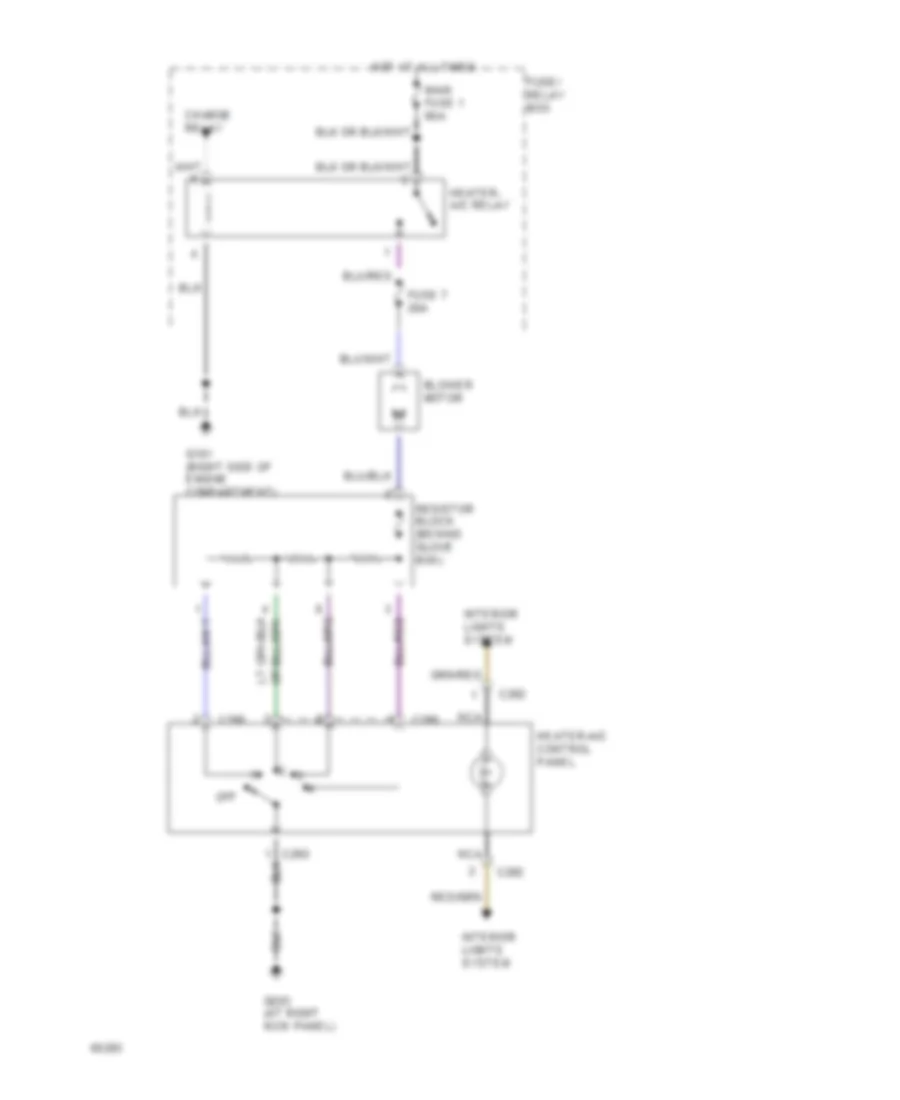
AIR CONDITIONING A/C Wiring Diagram for Isuzu Pickup S 1995 List of elements for A/C Wiring Diagram for Isuzu Pickup S 1995: 38 (2.3l) (2.3l: in fuse/relay box) (2.6l) 2.3l 2.6l A/c compressor clutch A/c dual pressure switch (behind left side of radiator grille) A/c switch A/c thermostat relay (2.6l: behind right side of i/p, at kick panel) Blower motor C 1995 vftc C210 C214 C282 C289 C290 Charge relay Electronic thermostat (behind glove box) Engine control module (at left kick panel) Evaporator temperature sensor Fast idle solenoid valve (right rear of engine) Fast idle solenoid valve (right side of engine compartment on inner fender panel) Fuse 7 20a Fuse 8 10a Fuse/ relay box G101 (right side of engine compartment) G119 (right front of engine, on intake manifold) G202 (below left side of i/p, behind ecm) G203 (at right kick panel) Heater- a/c relay Heater-a/c control panel Hot at all times Interior lights system Main fuse 1 60a Nca Off Resistor block (behind glove box) Solid state Heater Wiring Diagram for Isuzu Pickup S 1995 List of elements for Heater Wiring Diagram for Isuzu Pickup S 1995: 17 Blower motor C282 C289 C290 Charge relay Fuse 7 20a Fuse/ relay box G101 (right side of engine compartment) G203 (at right kick panel) Heater- a/c relay Heater-a/c control panel Hot at all times Interior lights system Main fuse 1 60a Nca Off Resistor block (behind glove box)
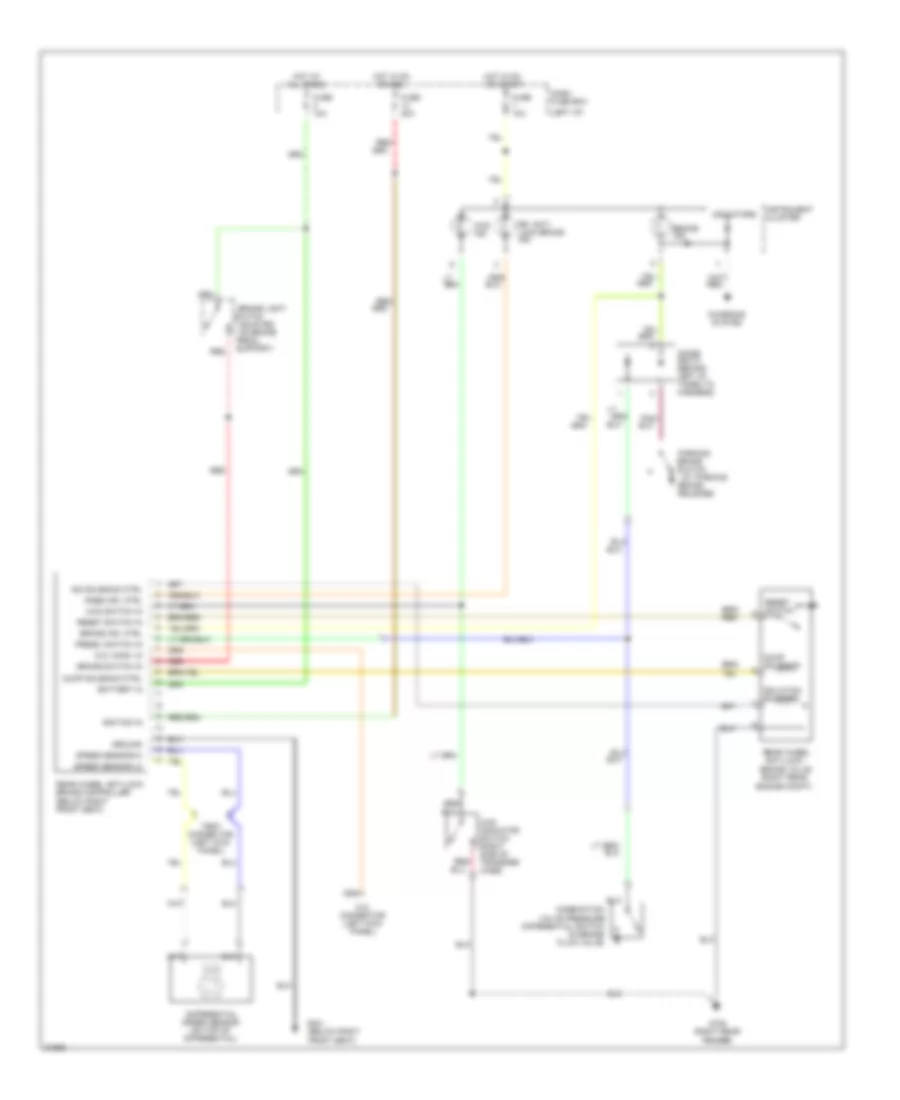
ANTI-LOCK BRAKES Anti-lock Brake Wiring Diagrams for Isuzu Pickup S 1995 List of elements for Anti-lock Brake Wiring Diagrams for Isuzu Pickup S 1995: 57 (at parking (below right front seat) (left i/p) (mounted on brake 4wd ind. 4wd indicator switch (right side of transfer case) 4wd switch in Battery in Brake Brake ind. Brake ind. ctrl Brake light Brake switch Brake switch in Brake valve (right rear Charging system Combination valve pressure differential switch (in brake fluid valve) D.g. conn. in D.g. connector (left kick panel) Dash fuse box Differential speed sensor (on top of differential) Diode box d (behind left i/p, taped to harness) Dump solenoid Dump solenoid ctrl Engine compt) Fuse 10a Fuse 20a G105 (right rear fender) G301 Ground Hot at all times Hot in on Hot in on or start Ignition in Indicators Instrument cluster Iso solenoid ctrl Isolation solenoid Or acc Parking Pedal Pnk/ Press. switch in Rabs ind. ctrl Rear wheel anti-lock Rear wheel anti-lock brake controller (below right front seat) Red Red/ Release) Reset switch Reset switch in Rr. anti- lock brake ind. Speed sensor-hi Speed sensor-lo Support) Switch Test connector (left kick panel)
COMPUTER DATA LINES
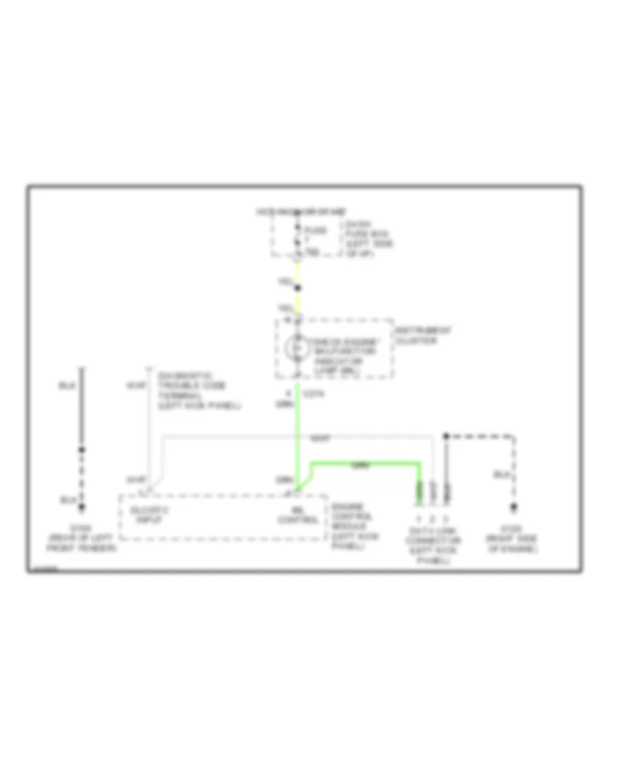
2.3L 2.3L, Computer Data Lines for Isuzu Pickup S 1995 List of elements for 2.3L, Computer Data Lines for Isuzu Pickup S 1995: 15 "check engine" malfunction indicator lamp (mil) (rear of left front fender) (right side of engine) C274 Dash fuse box (left side of i/p) Data link connector (left kick panel) Diagnostic trouble code terminal (left kick panel) Dlc/dtc input Engine control module (left kick panel) Fuse 10a G104 G120 Hot in on or start Instrument cluster Mil control
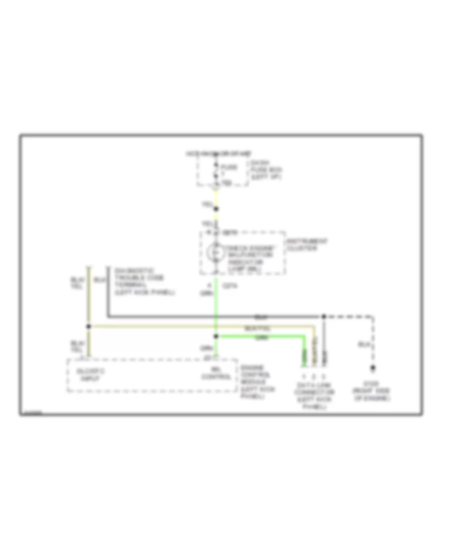
2.6L 2.6L, Computer Data Lines for Isuzu Pickup S 1995 List of elements for 2.6L, Computer Data Lines for Isuzu Pickup S 1995: 14 "check engine" malfunction indicator lamp (mil) (right side of engine) C274 C275 Dash fuse box (left i/p) Data link connector (left kick panel) Diagnostic trouble code terminal (left kick panel) Dlc/dtc input Engine control module (left kick panel) Fuse 10a G120 Hot in on or start Instrument cluster Mil control
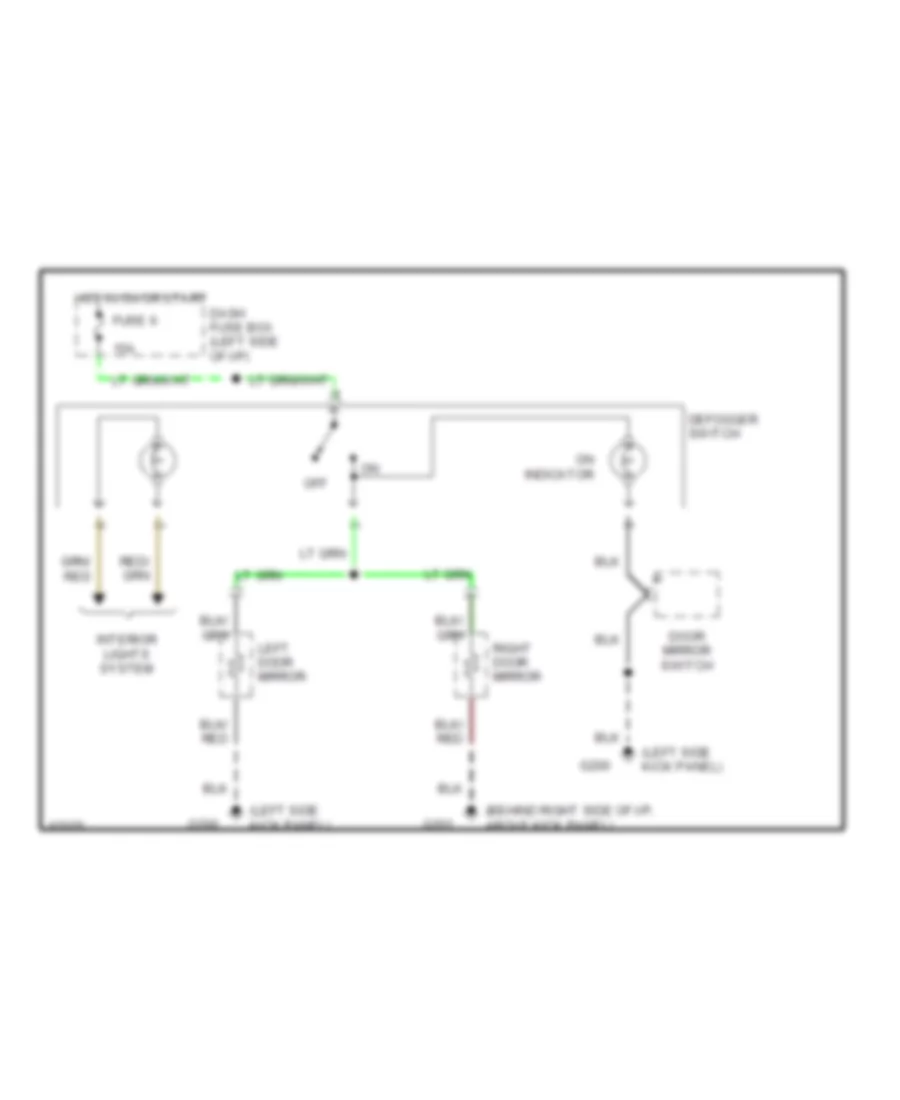
DEFOGGERS Heated Mirrors Wiring Diagram for Isuzu Pickup S 1995 List of elements for Heated Mirrors Wiring Diagram for Isuzu Pickup S 1995: 15 (behind right side of i/p, above kick panel) (left side kick panel) 15a Dash fuse box (left side of i/p) Defogger switch Door mirror switch Fuse 6 G200 G201 Hot in on or start Interior lights system Left door mirror Off On indicator Right door mirror
ENGINE PERFORMANCE
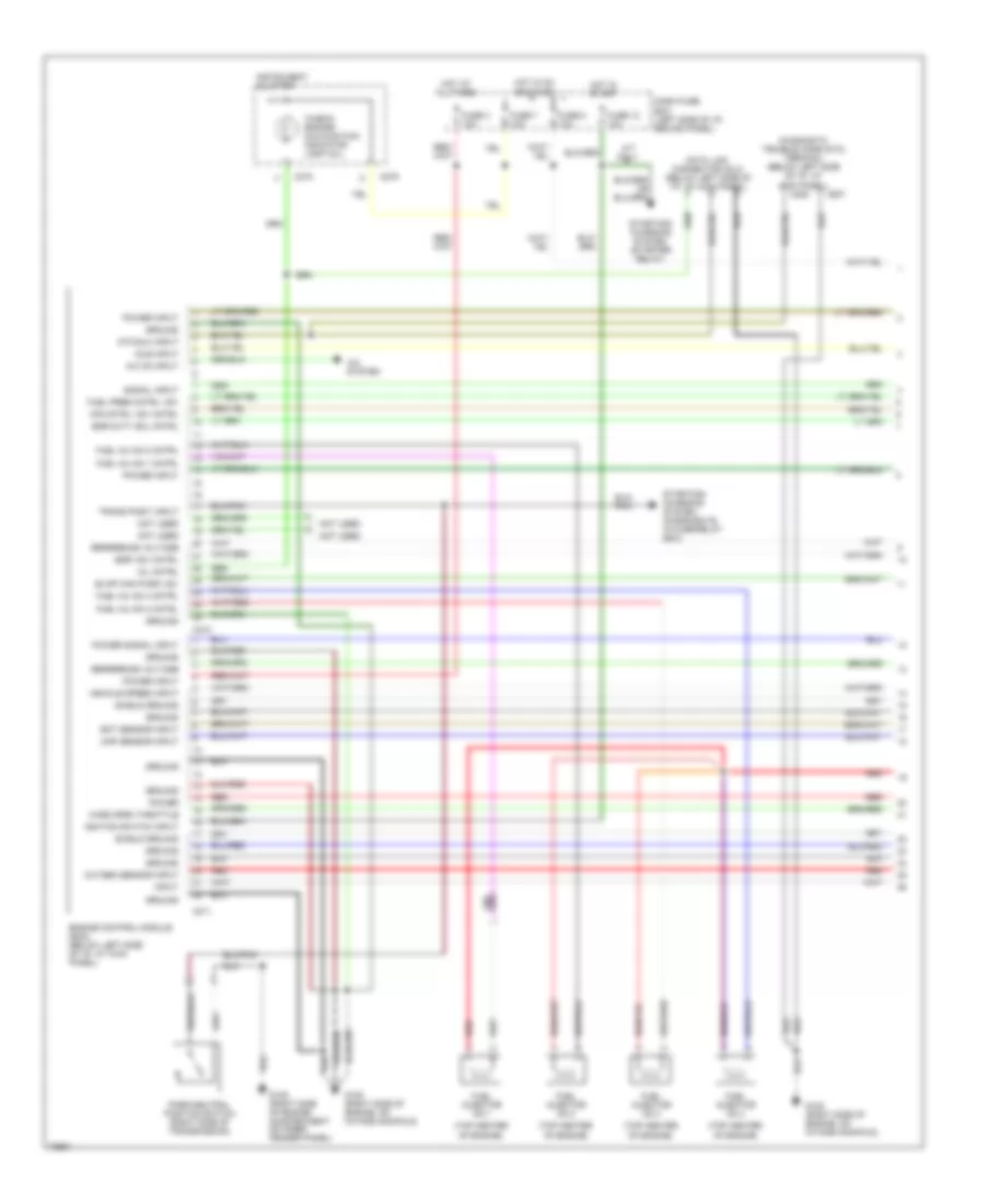
2.3L 2.3L, Engine Performance Wiring Diagrams (1 of 2) for Isuzu Pickup S 1995 List of elements for 2.3L, Engine Performance Wiring Diagrams (1 of 2) for Isuzu Pickup S 1995: 56 "check engine" malfunction indicator lamp (mil) (left side of engine compartment, on inner fender panel) (right side of engine compartment, on inner fender panel) (top center of engine, on rear of carburetor) A/c on input Air conditioning system Air inj react vsv cont Air management valve (amv) C213 C214 C221 C222 C274 C275 Dash fuse box (left side of i/p, behind panel) Data link connector (dlc) (below left side of i/p, at kick panel) Diagnostic trouble code (dtc) terminal (below left side of i/p, at kick panel) Dlc/dtc input Duty sol control Duty solenoid (top center of engine, in front of carburetor) Dwell lead (right side of engine compartment, taped to harness) Ect sensor input Efe heater relay cont Egr vsv control Engine control module (ecm) (below left side of i/p, at kick panel) Engine control module (ecm) relay Engine rpm input Evap cnstr purge vsv Evaporative emission canister purge vacuum switching valve (right side of engine compartment, on inner fender panel) Exhaust gas recirculation (egr) vacuum switching valve (calif only) Exhaust gas temp sen Fuse 1 10a Fuse 3 10a Fuse 7 10a Fuse 8 10a Fuse/relay box (right side of engine compartment, on inner fender panel) G101 (right side of engine compartment, on inner fender panel) G104 (left rear corner of engine compartment, on inner fender panel) G131 (right side of engine, on intake manifold) Ground Hot at all times Hot in on or start Idle vacuum switch in Ignition input Instrument cluster Manifold absolute pressure (map) vacuum switching valve Map sensor input Map vsv control Mil control Oxygen sensor (lower left side of engine, in exhaust manifold) Oxygen sensor input Power input Ref voltage Slow cut sol control Slow cut solenoid Vss input 2.3L, Engine Performance Wiring Diagrams (2 of 2) for Isuzu Pickup S 1995 List of elements for 2.3L, Engine Performance Wiring Diagrams (2 of 2) for Isuzu Pickup S 1995: 45 (right side of engine, in intake manifold) Accelerator switch (below left side of i/p, on top of accelerator pedal) C274 Charge relay Charging system Choke heater Dash fuse box (left side of i/p, behind panel) Distributor assembly (right rear corner of engine) Distributor cap Efe heater (right side of engine, below caburetor) Efe heater relay Engine coolant temperature (ect) sensor Exhaust gas temperature sensor (calif. only) (lower right side of engine compartment, below intake manifold) Fuse 2 10a Fuse 6 10a Fuse 9 15a Fuse/relay box (right side of engine compartment, on inner fender panel) Fuse/relay box (right side of engine compartment, on inner fender panel) G105 (right side of engine compartment, on inner fender panel) Generator (lower left of engine) Ground Heater Hot at all times Hot in on or start Idle vacuum switch (right side of engine compartment, on inner fender panel) Ignition coil (right rear corner of engine) Ignition control module solid- state: do not check resistance Ignition vacuum switching valve (right side of engine compartment on inner fender panel) Indicator control Instrument cluster Main fuse 1 60a Manifold absolute pressure (map) sensor (right side of of engine compartment, on inner fender panel) Nca Noise condenser (right side of engine, on intake manifold) Pick- up coil Pick-up coil control Power Primary Primary output control Secondary Spark plugs Timer core Vehicle speed sensor Voltage regulator Wire coil
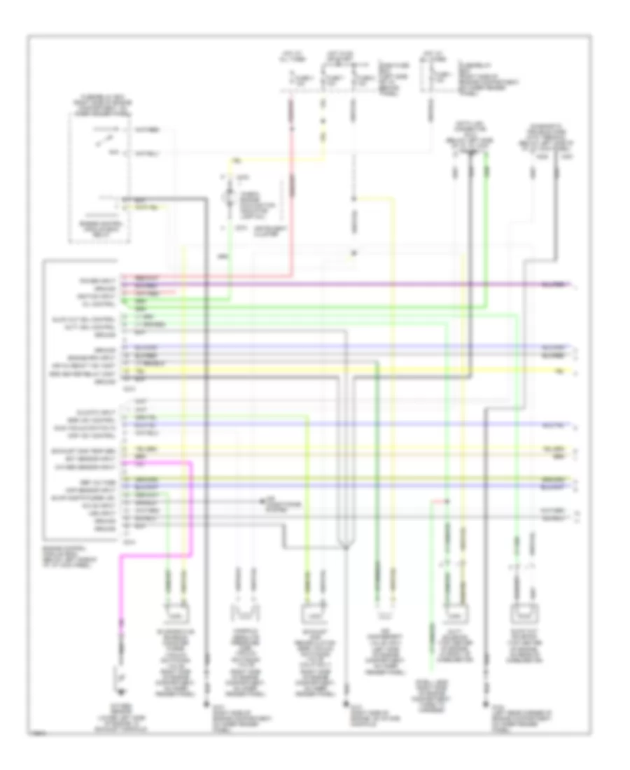
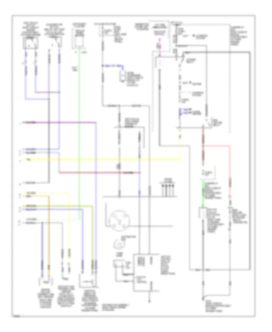
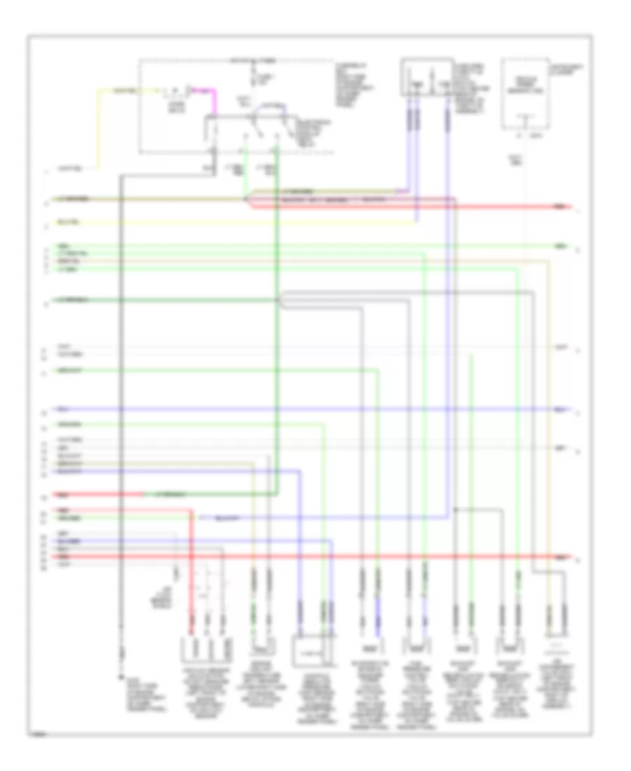
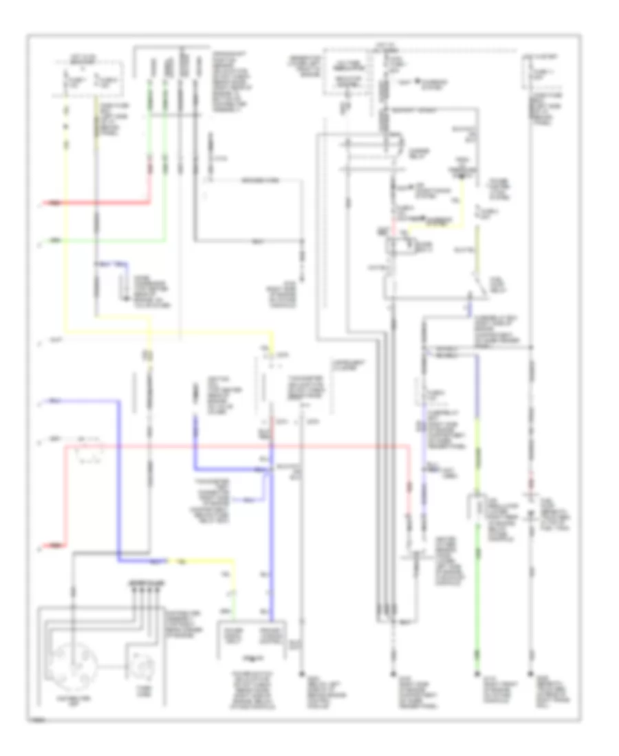
2.6L 2.6L, Engine Performance Wiring Diagrams (1 of 3) for Isuzu Pickup S 1995 List of elements for 2.6L, Engine Performance Wiring Diagrams (1 of 3) for Isuzu Pickup S 1995: 61 "check engine" malfunction indicator lamp (mil) (top center of engine) A/c on input A/c system A/t only Air cntrl vsv cntrl C207 C208 C210 C211 C274 C275 Dash fuse box (left side of i/p, behind panel) Data link connector (dlc) (below left side of i/p, at kick panel) Diagnostic trouble code (dtc) terminal (below left side of i/p, at kick panel) Dtc/dlc input Ect sensor input Egr duty sol cntrl Egr vsv cntrl Engine control module (ecm) (below left side of i/p, at kick panel) Evap can purg vsv Fuel inj no.1 cntrl Fuel inj no.2 cntrl Fuel inj no.3 cntrl Fuel inj no.4 cntrl Fuel injector no.1 Fuel injector no.2 Fuel injector no.3 Fuel injector no.4 Fuel pres cntrl vsv Fuse 12 10a Fuse 3 10a Fuse 7 10a Fuse 8 10a G105 (right side of engine compartment on inner fender panel) G120 (right side of engine, on intake manifold) Ground Hot at all times Hot in on or start Hot in start Idle input Ignition switch input Input Instrument cluster Map sensor input Mil cntrl Not used Oxygen sensor input Park/neutral position switch (right side of transmission) Power Power input Power signal input Red Reference voltage Shield ground Signal input Starting/ charging system (diode box b, in fuse/relay box) Starting/ charging system (starter relay) Trans posit input Vehicle speed input Wide open throttle 2.6L, Engine Performance Wiring Diagrams (2 of 3) for Isuzu Pickup S 1995 List of elements for 2.6L, Engine Performance Wiring Diagrams (2 of 3) for Isuzu Pickup S 1995: 30 (lower right side of engine, below intake manifold) (right side of engine compartment, on inner fender panel) (top center rear of engine on valve cover) (top center rear of engine, on valve cover) Air flow sensor (solid state: do not measure resistance) (left front of engine compartment, on air flow sensor) Air flow sensor shield Air management valve (amv) (left front of engine compartment, right of airflow assembly) C274 Cluster Diode box b Electronic control module (ecm) relay Engine coolant temperature (ect) sensor Evaporative emission canister purge vacuum switching valve Exhaust gas recirculation (egr) duty solenoid (calif. only) Exhaust gas recirculation (egr) vacuum switching valve (calif. only) Fuel pressure control valve vacuum switching valve Fuse 1 15a Fuse/relay box (right side of engine compartment, on inner fender panel) G105 (right side of engine compartment, on inner fender panel) Ground Hot at all times Idle Instrument Manifold absolute pressure (map) sensor (right side of engine compartment, on inner fender panel) Output Power Red Vehicle speed sensor (vss) Wide open throttle (wot) switch (top center rear of engine, on throttle assembly) Wot 2.6L, Engine Performance Wiring Diagrams (3 of 3) for Isuzu Pickup S 1995 List of elements for 2.6L, Engine Performance Wiring Diagrams (3 of 3) for Isuzu Pickup S 1995: 57 (not used) Air conditioning system Air regulator (lower right rear of engine, below intake manifold) Braided wire C134 C274 C275 Charge relay Charging system Coil wire Crankshaft position sensor (solid state: do not check resistance) (right rear of engine, in bottom of distributer assembly) Dash fuse box (left side of i/p, behind panel) Diode box a Distributer assembly (top right rear corner of engine) Distributer cap From oil pressure switch Fuel pump (beneath truck bed, in top of fuel tank) Fuel pump relay Fuse 11 20a Fuse 2 20a Fuse 6 10a Fuse 7 10a Fuse 9 15a Fuse/relay box (right side of engine compartment, on inner fender panel) Fuse/relay box (right side of engine compartment, on inner fender panel) G105 (right side of engine compartment, on inner fender panel) G119 (right front of engine, on intake manifold) G120 (right side of engine on intake manifold) G202 (below left side of i/p behind engine control module) G409 (beneath truck bed on rear of right frame rail) Generator (lower left front of engine) Ground Heated oxygen sensor (ho2s) (lower left side of engine, in exhaust manifold) Hot at all times Hot in on or start Hot in start Ignition coil (top center rear of engine, on valve cover) Indicator control Instrument cluster Main fuse 1 60a Nca Noise condensor (top center rear of engine, on valve cover) Power Power distrib- ution system Power signal input Power switch (solid state: do not check resistance) (right side of engine, below intake manifold) Primary Primary winding control Red Reference voltage Secondary Signal output Spark plugs Tachometer (solid-state: do not check resistance) Tachometer test connector (right side of engine compartment, behind fuse/ relay box) Timer core Voltage regulator
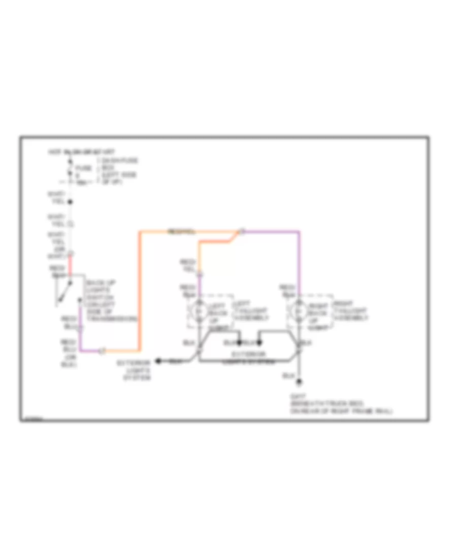
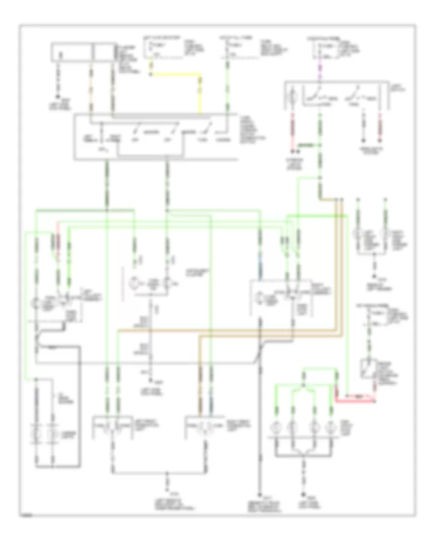
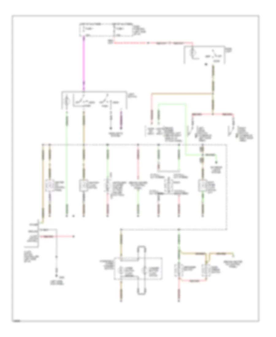
EXTERIOR LIGHTS Back-up Lamps Wiring Diagram for Isuzu Pickup S 1995 List of elements for Back-up Lamps Wiring Diagram for Isuzu Pickup S 1995: 10 Back up lights switch (on left side of transmission) Dash fuse box (left side of i/p) Exterior lights system Fuse 10a G417 (beneath truck bed, on rear of right frame rail) Hot in on or start Left back up light Left taillight assembly Right back up light Right taillight assembly Exterior Lamps Wiring Diagram for Isuzu Pickup S 1995 List of elements for Exterior Lamps Wiring Diagram for Isuzu Pickup S 1995: 50 (beneath truck bed, on rear of right frame rail) (left rear of eng compt, on inner fender panel) (left side kick panel) (rear of left fender) 10a 15a Brake light switch (on brake pedal support) C274 C275 Dash fuse box (left side of i/p) Flasher unit (behind left side of i/p, above kick panel) Fuse 1 Fuse 2 Fuse 3 Fuse 7 Fuse/ relay box (right side of eng compt) G104 G200 G417 Gnd Hazard Head Headlights system High mount stop lamp Hot at all times Hot in on or start Instrument cluster Interior lights system Left front combination light Left front side marker light Left taillight assembly Left turn License lights Light switch Off Output Park Park/ stop light Power Red Right front combination light Right front side marker light Right taillight assembly Right turn Stop Turn Turn signal ind. Turn signal light Turn signal/ hazard warning switch (combination switch) W/ rear bumper
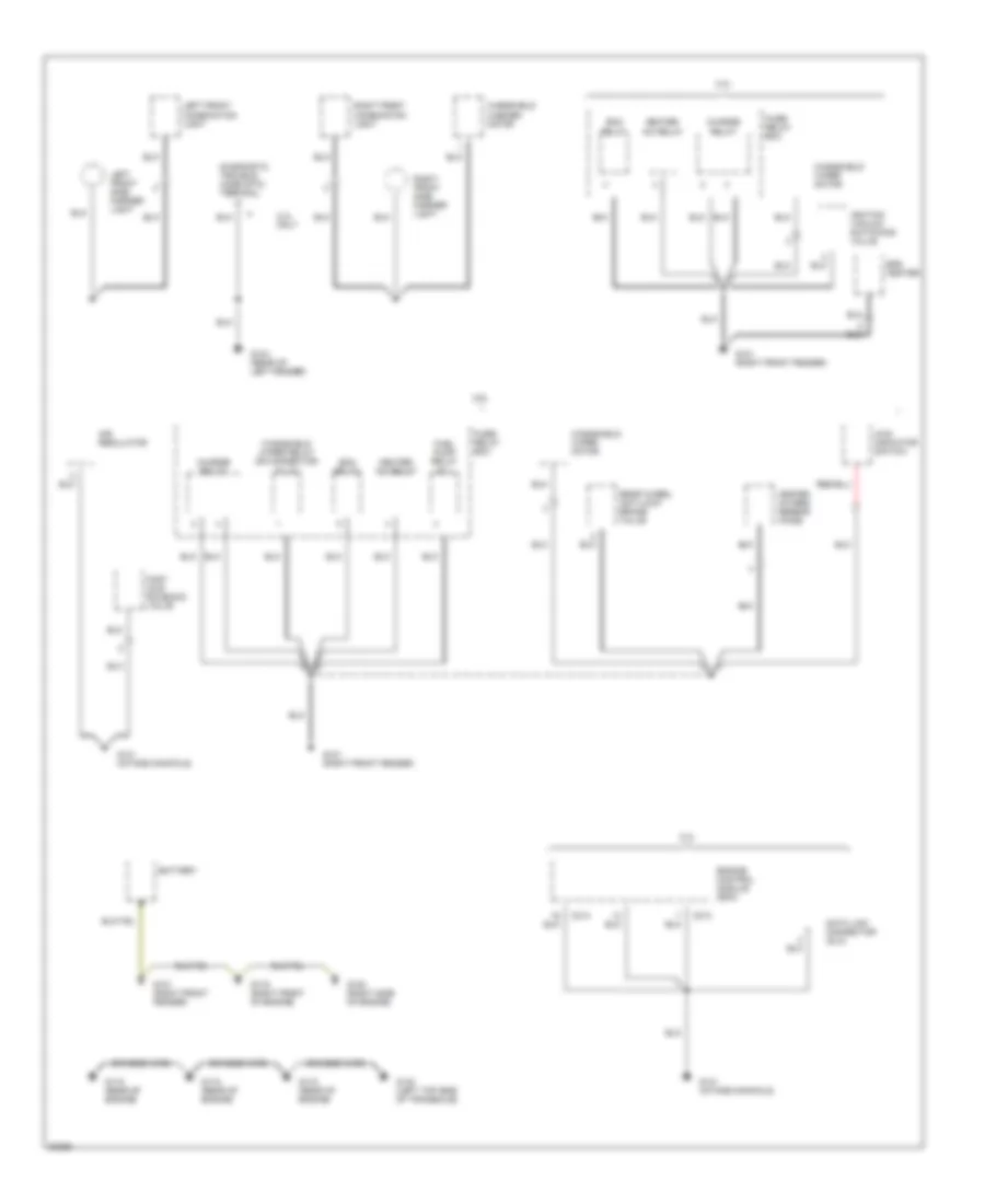
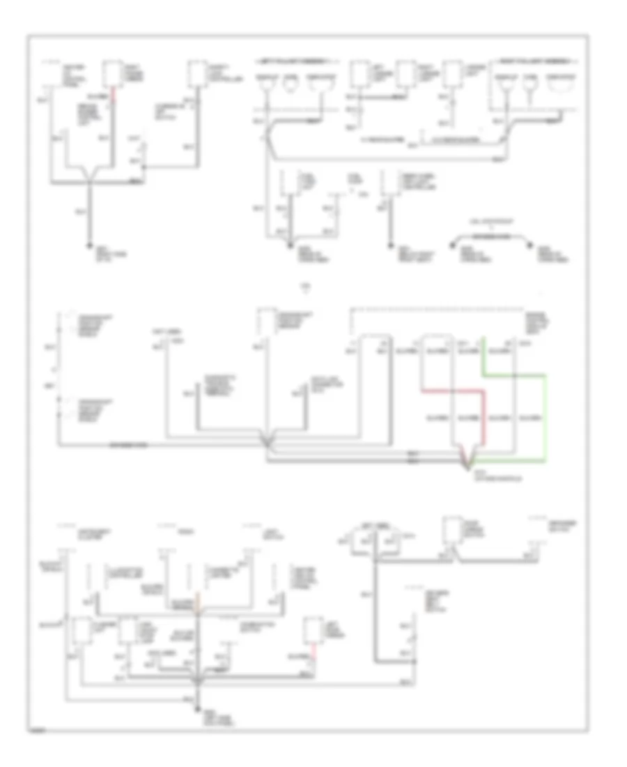
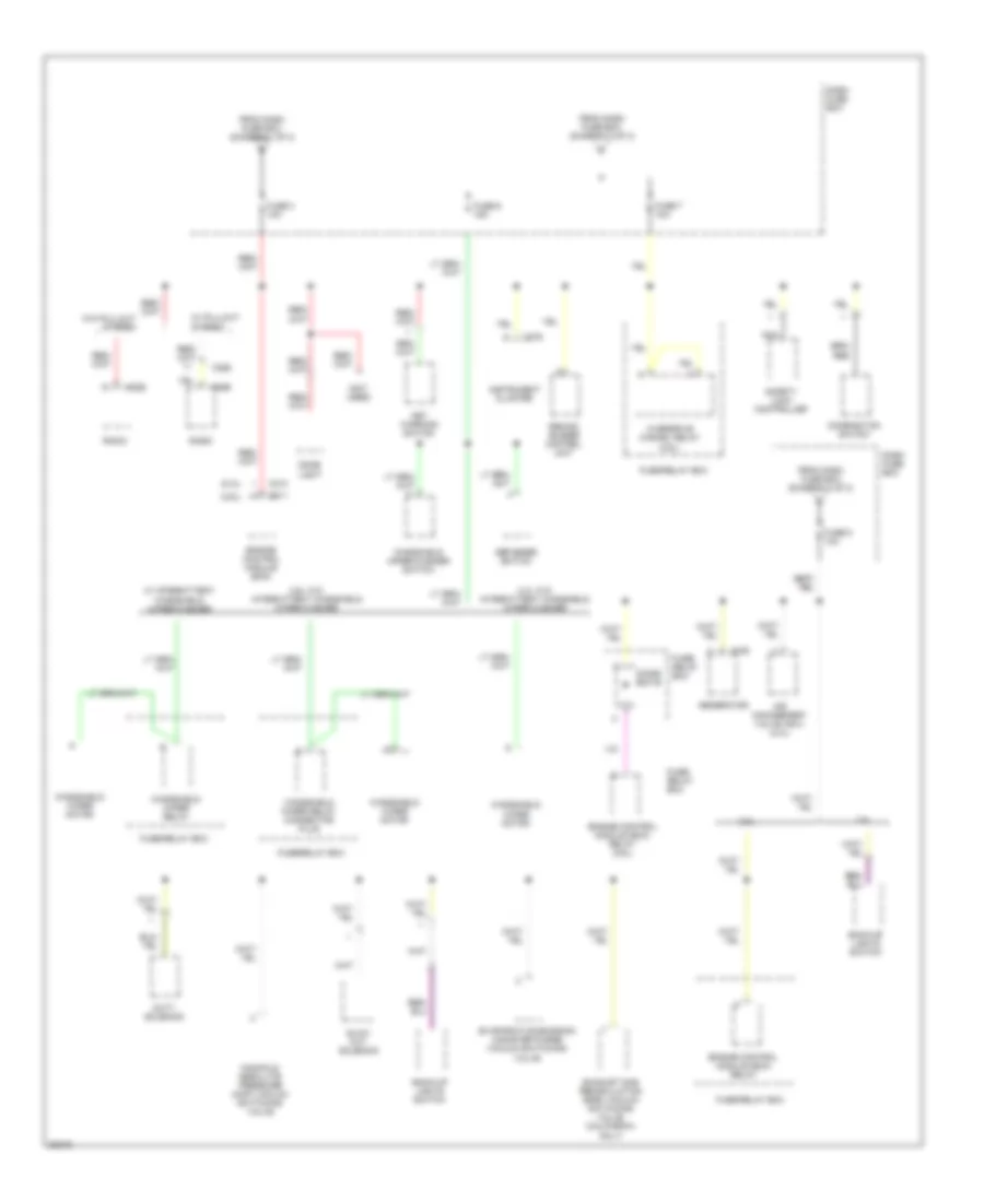
GROUND DISTRIBUTION Ground Distribution Wiring Diagram (1 of 2) for Isuzu Pickup S 1995 List of elements for Ground Distribution Wiring Diagram (1 of 2) for Isuzu Pickup S 1995: 36 2.3l 2.3l only 2.6l 4wd indicator switch Air regulator Battery Braided wire C213 C214 Charge relay Data link connector (dlc) Diagnostic trouble code (dtc) terminal Ecm relay Efe heater Engine control module (ecm) Fast idle solenoid valve Fuel pump relay no.1 Fuse/ relay box G101 (right front fender) G104 (rear of left fender) G115 (rear of engine) G119 (right front of engine) G120 (right side of engine) G130 (left top side of transaxle) G131 (intake manifold) Heated oxygen sensor (ho2s) Heater- a/c relay Ignition vacuum switching valve Left front combination light Left front side marker light Rear wheel anti-lock brake valve Right front combination light Right front side marker light Windshield washer motor Windshield wiper motor Windshield wiper relay or connector plug Ground Distribution Wiring Diagram (2 of 2) for Isuzu Pickup S 1995 List of elements for Ground Distribution Wiring Diagram (2 of 2) for Isuzu Pickup S 1995: 49 (not used) 2.6l 2.6l 4wd pickup Back up Braided wire C210 C211 C224 C314 Cigarette lighter Combination switch Crankshaft position sensor Crankshaft position sensor shield Data link connector (dlc) Defogger switch Diagnostic trouble code (dtc) terminal Door mirror switch Driver's seat belt switch Engine control module (ecm) Flasher unit Fuel pump Fuel tank unit G131 (intake manifold) G200 (left side kick panel) G201 (right side of i/p) G301 (below right front seat) G409 (rear of cargo bed) Heater and a/c control panel Heater- a/c control panel High mount stop lamp Illumination controller Instrument cluster Left door mirror Left license light Left taillight assembly License light Light switch Overdrive off switch Park/stop Radio Rear wheel anti-lock controller Remind buzzer control unit Right license light Right power mirror Right taillight assembly Safety lock controller Turn W/ rear bumper W/o rear bumper
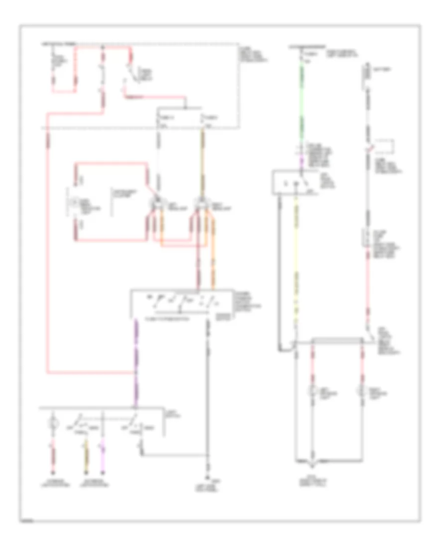
HEADLIGHTS Headlight Wiring Diagram for Isuzu Pickup S 1995 List of elements for Headlight Wiring Diagram for Isuzu Pickup S 1995: 37 (left side kick panel) (right side of safety wall) 10a 15a Battery C274 Dash fuse box (left side of i/p) Dimmer/ passing switch (combination switch) Dimming switch Exterior lights system Flash to pass switch Fuse 10 Fuse 6 Fuse 9 Fuse/ relay box (right side of eng compt) G123 G200 Head Head- light relay High beam indicator light Hot at all times Hot in on or start In-line fuse 15a (right side of eng compt, near fuse/ relay box) Instrument cluster Interior lights system Left headlamp Left off-road light Light switch Main fuse 2 30a Off Off- road lights relay (right rear of eng compt) Off- road lights switch Park Red Right headlamp Right off-road light Splice connector (behind left side of i/p, near fuse relay box)
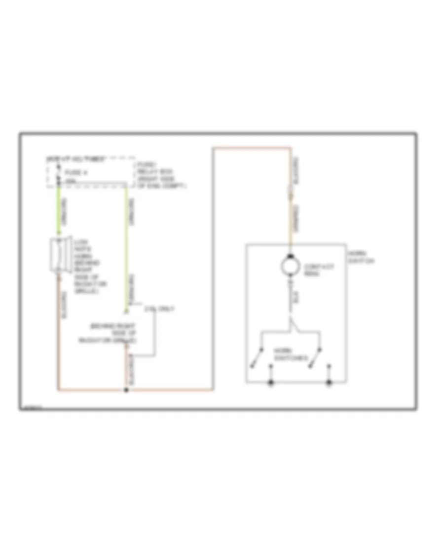
HORN Horn Wiring Diagram for Isuzu Pickup S 1995 List of elements for Horn Wiring Diagram for Isuzu Pickup S 1995: 10 (behind right side of radiator grille) 10a 2.6l only Contact ring Fuse 4 Fuse/ relay box (right side of eng compt) Horn switch Horn switches Hot at all times Low note horn (behind right side of radiator grille)
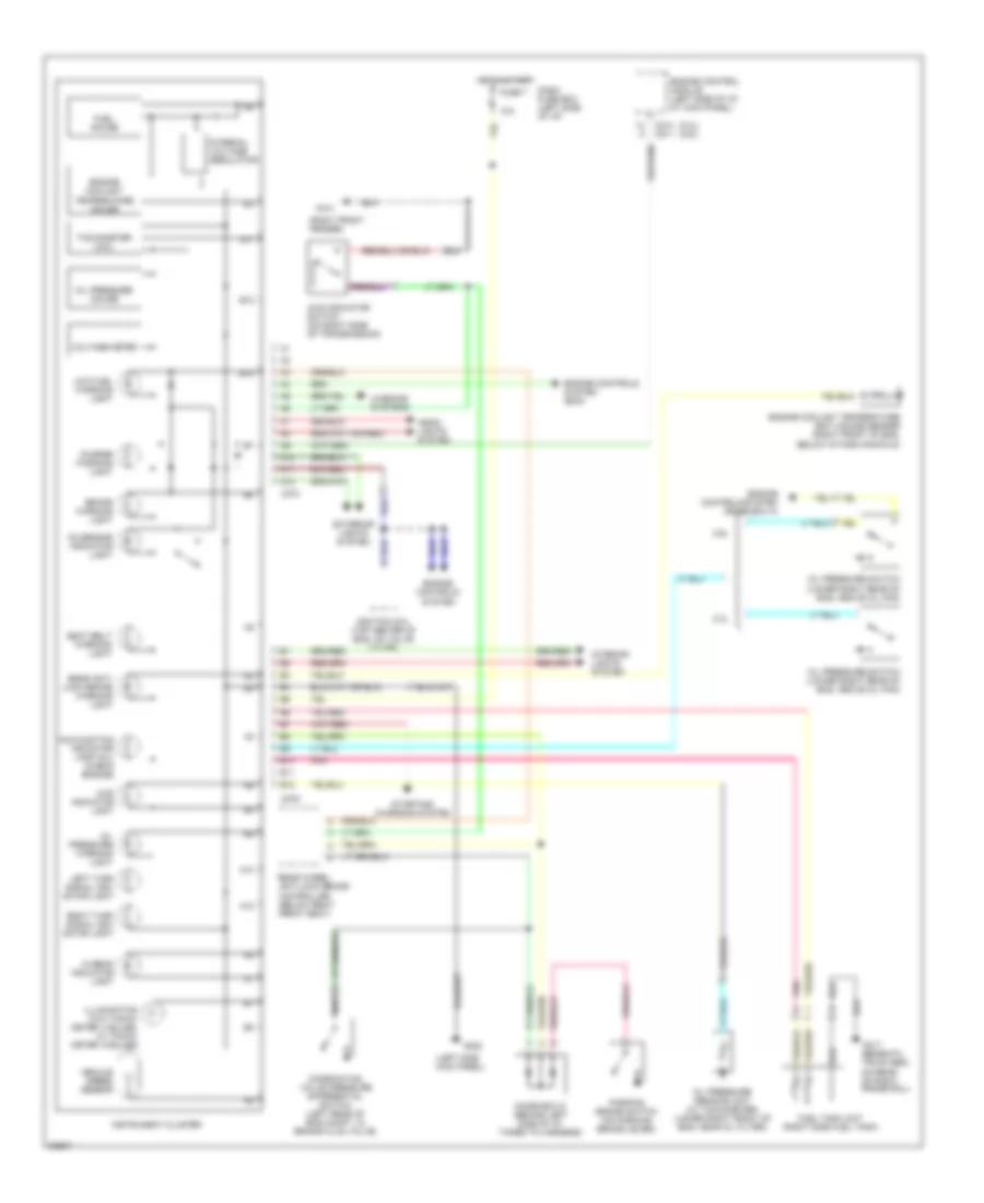
INSTRUMENT CLUSTER Instrument Cluster Wiring Diagram for Isuzu Pickup S 1995 List of elements for Instrument Cluster Wiring Diagram for Isuzu Pickup S 1995: 62 (2.3l) (2.6l) (left side kick panel) (right front fender) 10a 2.3l 2.6l 4wd indicator light 4wd indicator switch (on right side of transmission) A10 A11 A12 B10 B11 B12 Brake warning light C214 c211 C274 C275 Charge warning light Combination valve pressure differential switch (left rear of eng compt, in brake fluid valve) Dash fuse box (left side of i/p) Diode box d (behind left side of i/p, taped to harness) Engine control module (left side of i/p, at kick panel) Engine controls system Engine controls system (diode box a) Engine controls system (ecm) Engine coolant temperature (ect) gauge sender (right front of eng, below intake manifold) Engine coolant temperature gauge Exterior lights system Fuel gauge Fuel tank unit (right side fuel tank) Fuse 7 G101 G200 G417 (beneath truck bed, on rear of right frame rail) Head- lights system Hi beam indicator light Hot in start Ignition coil (top center of eng, on valve cover) Illumination (w/o tacho- meter: 2 bulbs, w/ tacho- meter: 9 bulbs) Instrument cluster Interior lights system Internal voltage regulator Left turn signal indi- cator light Low fuel warning light Malfunction indicator lamp (mil) (check engine) O2 sensor indicator light Oil pressure gauge Oil pressure sending unit (w/ tachometer) (lower right front of eng, near oil filter) Oil pressure switch (lower right rear of eng, above oil pan) Oil pressure warning light Parking brake switch (on parking brake lever) Pnk Rear anti- lock brake warning light Rear wheel anti-lock brake controller (below right front seat) Right turn signal indi- cator light Seat belt warning light Starting/ charging system Tachometer (2.6l) Vehicle speed sensor Voltage meter Warning systems
INTERIOR LIGHTS Interior Light Wiring Diagram for Isuzu Pickup S 1995 List of elements for Interior Light Wiring Diagram for Isuzu Pickup S 1995: 39 (behind heater a/c control panel) (left side kick panel) 10a Ashtray illumi- nation C275 Dash fuse box (left side of i/p) Defogger switch Dome light Door Door mirror switch Door sw input Exterior lights system Fuse 1 Fuse 3 G200 Ground Head Headlights system Heater a/c control panel Hot at all times Illumi- nation control Illumi- nation controller (left side of i/p) Instrument cluster (2 bulbs w/ tach, 9 bulbs w/o tach) Left door switch (in rear of left door area) Light switch Lights on input Off Park Power Radio Red Remind buzzer control unit (behind right side of i/p, at kick panel) Right door switch (in rear of right door area) Shift lever illumi- nation (a/t) W/ pull- out stereo W/o pull- out stereo Washer button illumi- nation Windshield wiper/ washer switch Wiper switch illumi- nation
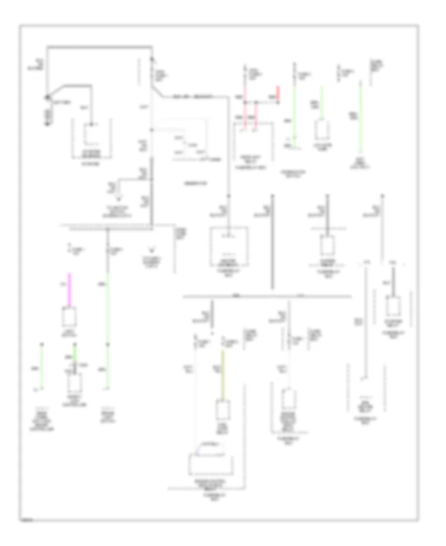
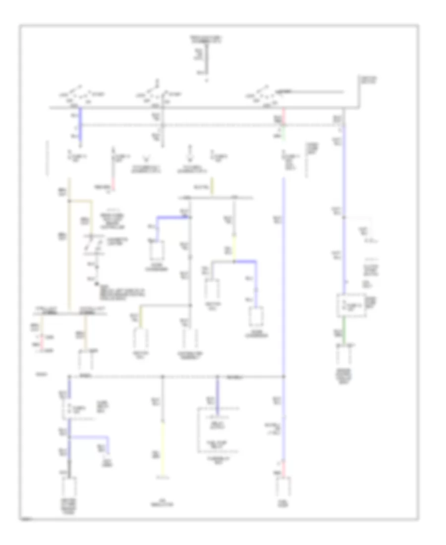
POWER DISTRIBUTION Power Distribution Wiring Diagram (1 of 3) for Isuzu Pickup S 1995 List of elements for Power Distribution Wiring Diagram (1 of 3) for Isuzu Pickup S 1995: 38 (not used) (2.6l only) 2.3l 2.6l Battery Brake light switch C105 C106 C325 Charge relay Combination switch Dash fuse box Efe heater relay Engine control module (ecm) relay Fuel pump relay Fuse 1 10a Fuse 1 15a Fuse 2 10a Fuse 2 20a Fuse 3 15a Fuse 4 10a Fuse/ relay box Fuse/relay box Generator Headlight relay Heater a/c relay Light switch Low note horn Main fuse 1 60a Main fuse 2 30a Nca Rear wheel anti-lock brake controller Red Safety lock controller Starter Starter relay Starter solenoid To fuse 3 (diagram 3 of 3) To ignition switch (diagram 2 0f 3) Power Distribution Wiring Diagram (2 of 3) for Isuzu Pickup S 1995 List of elements for Power Distribution Wiring Diagram (2 of 3) for Isuzu Pickup S 1995: 44 (not used) 2.3l 2.6l 2.6l only Acc Air regulator C211 C286 C295 Cigarette lighter Clutch start switch Dash fuse box Distributer assembly Engine control module (ecm) From main fuse 1 (diagram 1 of 3) Fuel pump Fuel pump relay Fuse 11 20a (2.6l only) Fuse 12 10a Fuse 13 15a Fuse 14 20a Fuse 6 10a Fuse 9 15a Fuse/ relay box Fuse/relay box G200 (below left side of i/p, behind engine control module (ecm)) Heated oxygen sensor (ho2s) Ignition coil Ignition switch Lock Nca Noise condenser Noise condensor Off On acc Radio Rear wheel anti-lock brake controller Red Relay output Start To fuse 8 (diagram 3 of 3) To fuses 6 & 7 (diagram 3 of 3) W/o pull-out stereo W/pull-out stereo Power Distribution Wiring Diagram (3 of 3) for Isuzu Pickup S 1995 List of elements for Power Distribution Wiring Diagram (3 of 3) for Isuzu Pickup S 1995: 51 (2.3l) (2.6l) (not used) 2.3l 2.3l w/o intermittent windshield wiper/washer 2.6l 2.6l w/o intermittent windshield wiper/washer Air management valve (amv) (2.3l) Back-up lights switch C106 C211 C213 C275 C286 C295 Combination switch Dash fuse box Defogger switch Diode box b Dome light Duty solenoid Engine control module (ecm) Engine control module (ecm) relay Engine control module (ecm) relay (2.6l) Evaporative emission canister purge vacuum switching valve Exhaust gas recirculation (egr) vacuum switching valve (california only) From dash fuse box (diagram 1 of 3) From dash fuse box (diagram 2 of 3) Fuse 3 10a Fuse 6 15a Fuse 7 10a Fuse 8 10a Fuse/ relay box Fuse/relay box Generator Instrument cluster Key warning switch Manifold absolute pressure (map) vacuum switching valve Nca Overdrive cancel relay Radio Remind buzzer control unit Safety lock controller Slow cut solenoid W/ intermittent windshield wiper/washer W/ pullout stereo W/o pullout stereo Windshield wiper motor Windshield wiper relay Windshield wiper relay connector plug Windshield wiper/washer switch
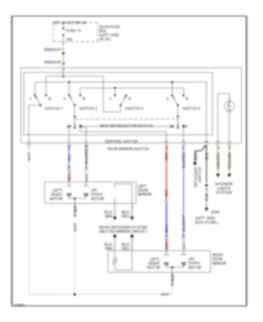
POWER MIRRORS Power Mirror Wiring Diagram for Isuzu Pickup S 1995 List of elements for Power Mirror Wiring Diagram for Isuzu Pickup S 1995: 21 (left side kick panel) 15a Control switch Dash fuse box (left side of i/p) Defogger switch Door mirror switch Fuse 13 G200 Hot in acc or on Interior lights system Left door mirror Left/ right motor Master selector switch Rear defogger system (heated mirror circuit) Red Right door mirror Switch 1 Switch 2 Switch 3 Switch 4 Up/ down motor
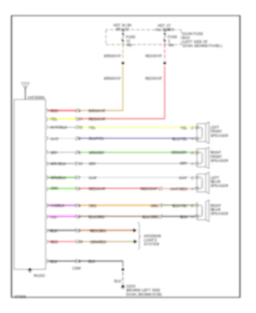
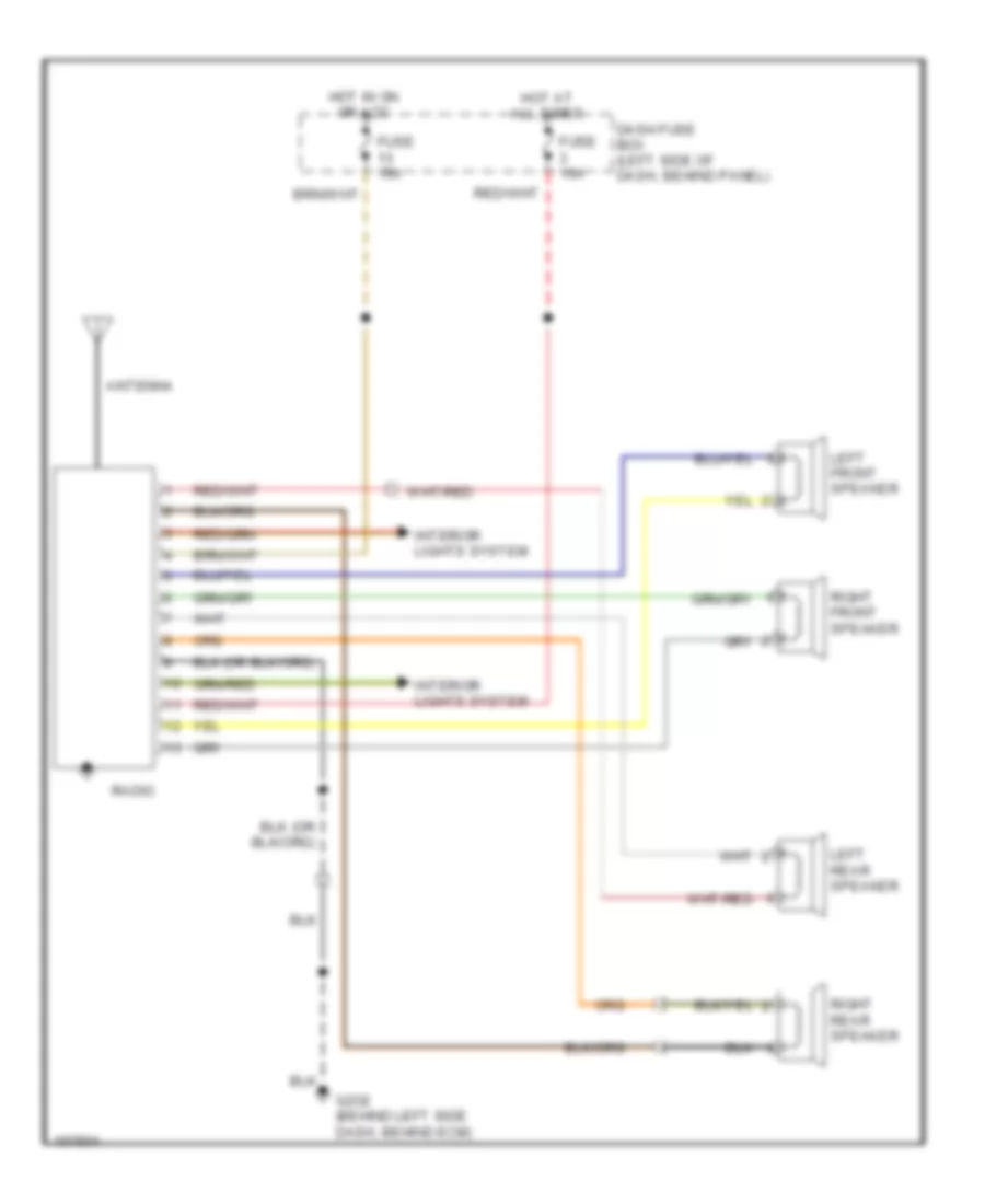
RADIO Radio Wiring Diagrams, with Pull-Out Stereo for Isuzu Pickup S 1995 List of elements for Radio Wiring Diagrams, with Pull-Out Stereo for Isuzu Pickup S 1995: 15 Antenna C296 Dash fuse box (left side of dash, behind panel) Fuse 10a Fuse 15a G2o2 (behind left side dash, behind ecm) Hot at all times Hot in on or acc Interior lights system Left front speaker Left rear speaker Radio Red Right front speaker Right rear speaker Radio Wiring Diagrams, without Pull-Out Stereo for Isuzu Pickup S 1995 List of elements for Radio Wiring Diagrams, without Pull-Out Stereo for Isuzu Pickup S 1995: 13 Antenna Dash fuse box (left side of dash, behind panel) Fuse 10a Fuse 15a G2o2 (behind left side dash, behind ecm) Hot at all times Hot in on or acc Interior lights system Left front speaker Left rear speaker Radio Right front speaker Right rear speaker
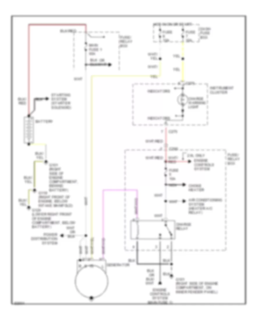
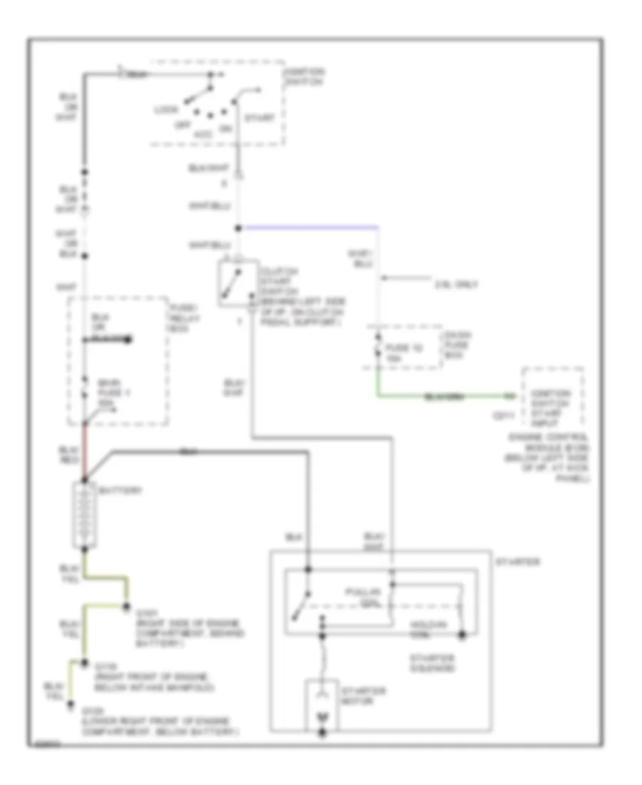
STARTING/CHARGING Charging Wiring Diagram for Isuzu Pickup S 1995 List of elements for Charging Wiring Diagram for Isuzu Pickup S 1995: 25 2.6l only Air conditioning system (heater a/c relay) Battery C200 C275 Charge relay Charge warning light Choke heater Dash fuse box Engine controls system Engine controls system (main fuse 1) Fuse 10a Fuse/ relay box G101 (right side of engine compartment, behind battery) G101 (right side of engine compartment, on inner fender panel) G119 (right front of engine, below intake manifold) G120 (lower right front of engine compartment, below battery) Generator Hot in on or start Indicators Instrument cluster Main fuse 1 60a Nca Power distribution system Starting system (starter solenoid) Starting Wiring Diagram for Isuzu Pickup S 1995 List of elements for Starting Wiring Diagram for Isuzu Pickup S 1995: 22 2.6l only Battery C211 Clutch start switch (behind left side of i/p, on clutch pedal support) Dash fuse box Engine control module (ecm) (below left side of i/p, at kick panel) Fuse 12 10a Fuse/ relay box G101 (right side of engine compartment, behind battery) G119 (right front of engine, below intake manifold) G120 (lower right front of engine compartment, below battery) Hold-in coil Ignition switch Ignition switch start input Lock Main fuse 1 60a Off acc Pull-in coil Start Starter Starter motor Starter solenoid
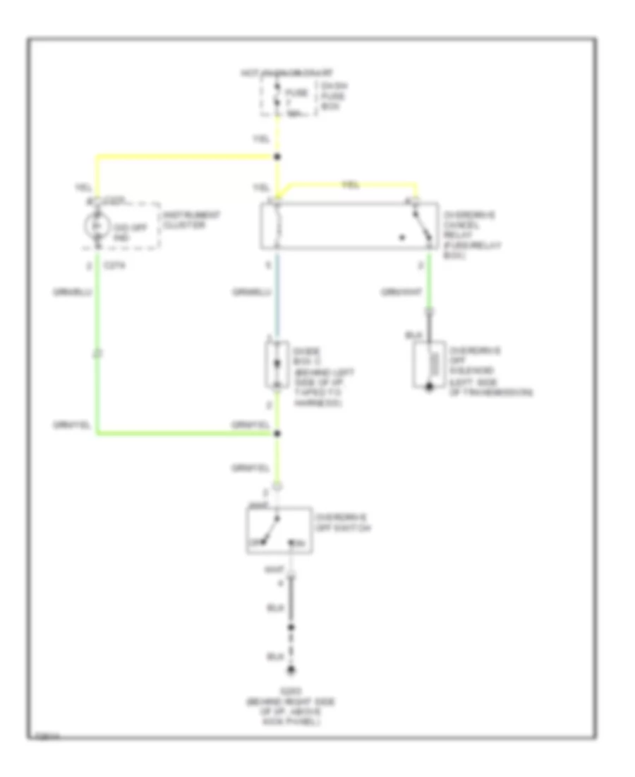
TRANSMISSION Transmission Wiring Diagram for Isuzu Pickup S 1995 List of elements for Transmission Wiring Diagram for Isuzu Pickup S 1995: 14 (left side of transmission) C274 C275 Dash fuse box Diode box c (behind left side of i/p, taped to harness) Fuse 10a G203 (behind right side of i/p, above kick panel) Hot in on or start Instrument cluster O/d off ind Off Overdrive cancel relay (fuse/relay box) Overdrive off solenoid Overdrive off switch
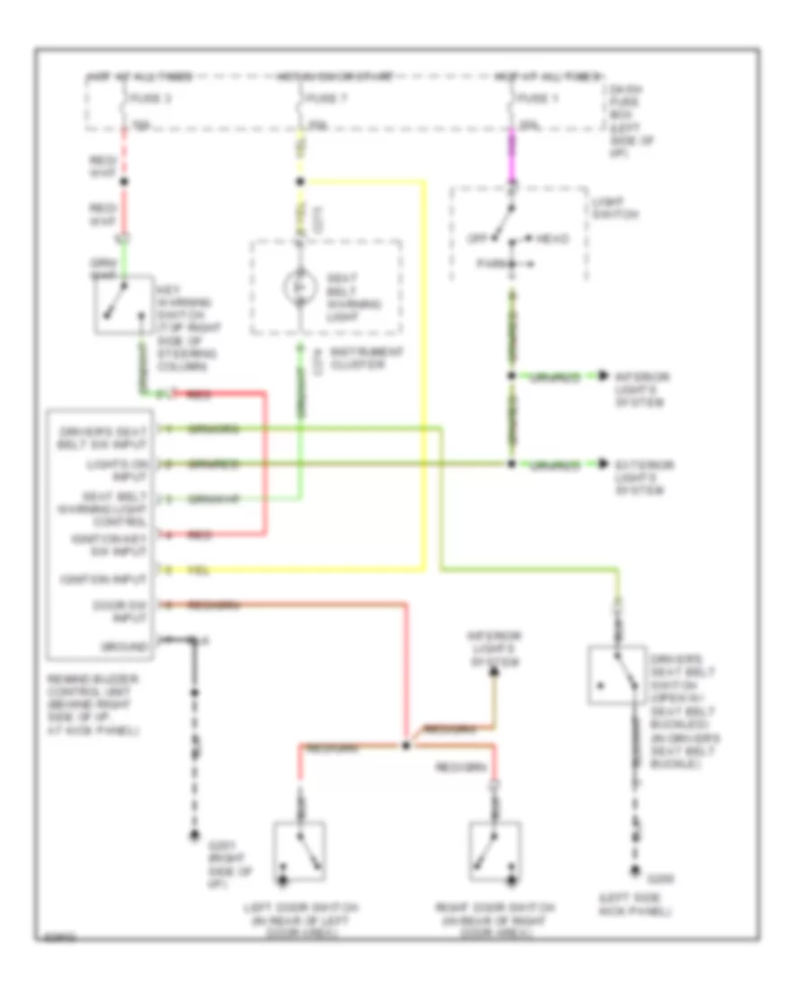
WARNING SYSTEMS Warning System Wiring Diagrams for Isuzu Pickup S 1995 List of elements for Warning System Wiring Diagrams for Isuzu Pickup S 1995: 34 (in driver's seat belt buckle) (left side kick panel) 10a C274 C275 Dash fuse box (left side of i/p) Door sw input Driver's seat belt sw input Driver's seat belt switch (open w/ seat belt buckled) Exterior lights system Fuse 1 Fuse 3 Fuse 7 G200 G201 (right side of i/p) Ground Head Hot at all times Hot in on or start Ignition input Ignition key sw input Instrument cluster Interior lights system Key warning switch (top right side of steering column) Left door switch (in rear of left door area) Light switch Lights-on input Off Park Red Remind buzzer control unit (behind right side of i/p, at kick panel) Right door switch (in rear of right door area) Seat belt warning light Seat belt warning light control
WIPER/WASHER
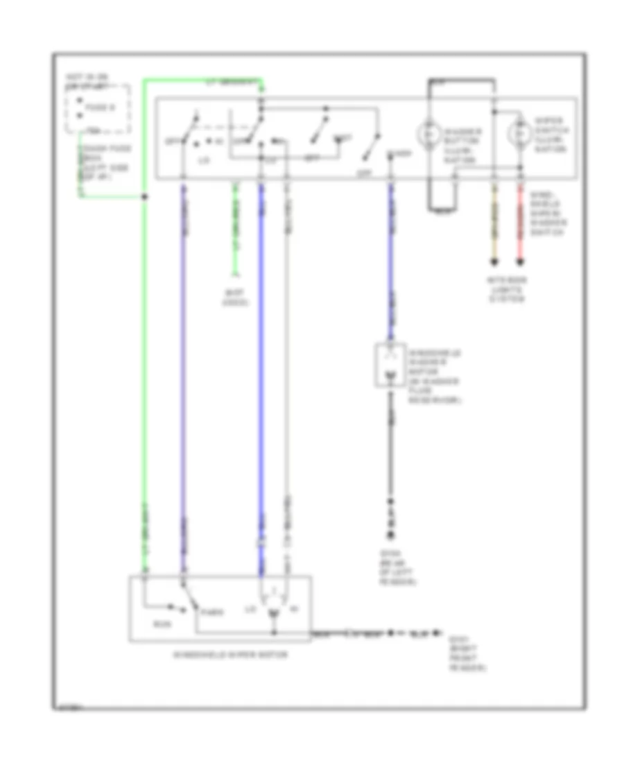
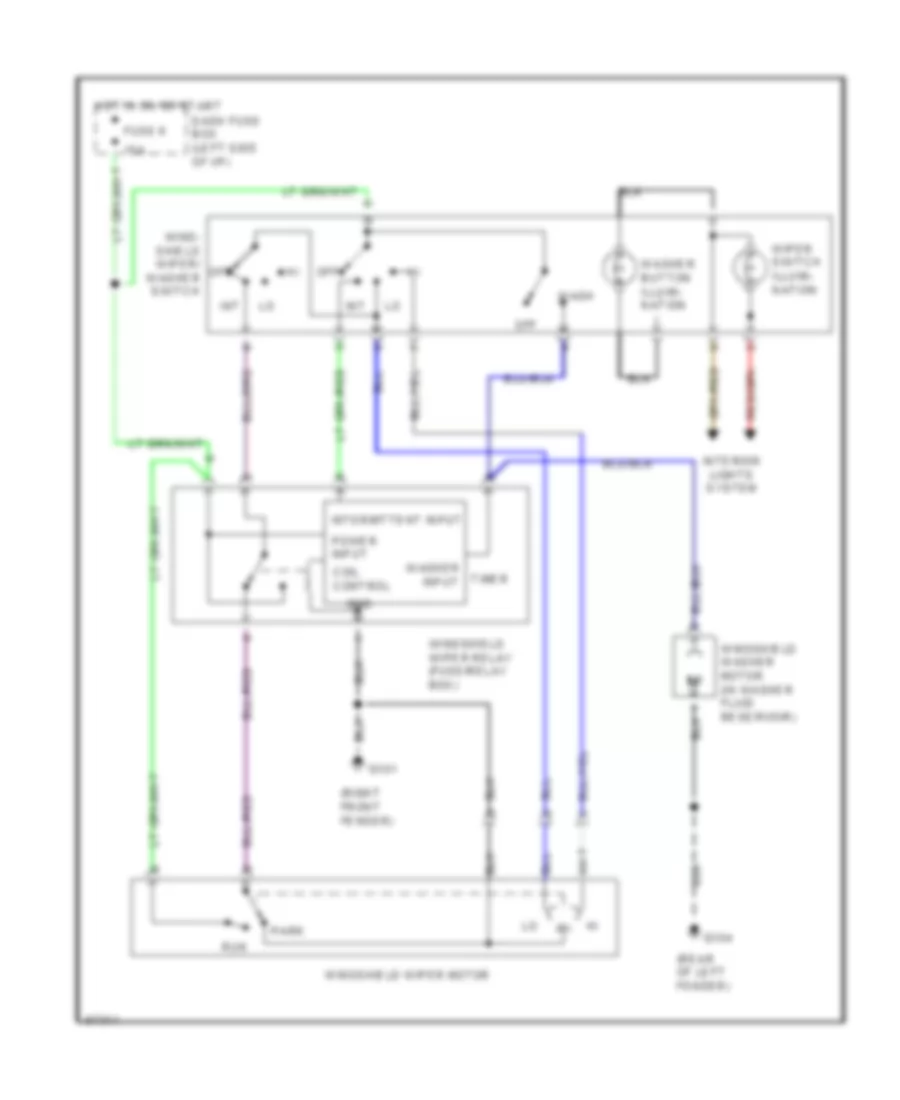
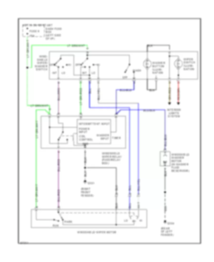
2.3L 2.3L, 2-Speed Wiper/Washer Wiring Diagram for Isuzu Pickup S 1995 List of elements for 2.3L, 2-Speed Wiper/Washer Wiring Diagram for Isuzu Pickup S 1995: 17 (not used) 15a Fuse 6 G101 (right front fender) G104 (rear of left fender) Hot in on or start Interior lights system Mist Off Park Run Wash Washer button illumi- nation Wind- shield wiper/ washer switch Windshield washer motor (in washer fluid reservoir) Windshield wiper motor Wiper switch illumi- nation Interval Wiper/Washer Wiring Diagram for Isuzu Pickup S 1995 List of elements for Interval Wiper/Washer Wiring Diagram for Isuzu Pickup S 1995: 26 (rear of left fender) (right front fender) 15a Coil control Dash fuse box (left side of i/p) Fuse 6 G101 G104 Gnd Hot in on or start Int Interior lights system Intermittent input Off Park Power input Run Timer Wash Washer button illumi- nation Washer input Wind- shield wiper/ washer switch Windshield washer motor (in washer fluid reservoir) Windshield wiper motor Windshield wiper relay (fuse/relay box) Wiper switch illumi- nation
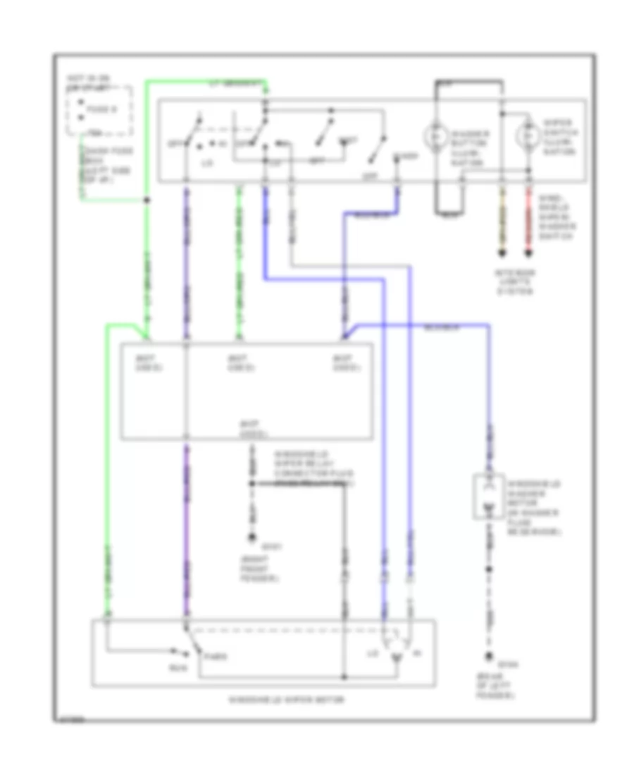
2.6L 2.6L, 2-Speed Wiper/Washer Wiring Diagram for Isuzu Pickup S 1995 List of elements for 2.6L, 2-Speed Wiper/Washer Wiring Diagram for Isuzu Pickup S 1995: 20 (not used) (rear of left fender) (right front fender) 15a Fuse 6 G101 G104 Hot in on or start Interior lights system Mist Off Park Run Wash Washer button illumi- nation Wind- shield wiper/ washer switch Windshield washer motor (in washer fluid reservoir) Windshield wiper motor Windshield wiper relay connector plug (fuse/relay box) Wiper switch illumi- nation Interval Wiper/Washer Wiring Diagram for Isuzu Pickup S 1995 List of elements for Interval Wiper/Washer Wiring Diagram for Isuzu Pickup S 1995: 26 (rear of left fender) (right front fender) 15a Coil control Dash fuse box (left side of i/p) Fuse 6 G101 G104 Gnd Hot in on or start Int Interior lights system Intermittent input Off Park Power input Run Timer Wash Washer button illumi- nation Washer input Wind- shield wiper/ washer switch Windshield washer motor (in washer fluid reservoir) Windshield wiper motor Windshield wiper relay (fuse/relay box) Wiper switch illumi- nation