Diagram sections — 28 (60 total)
AIR CONDITIONING ANTI-LOCK BRAKES ANTI-THEFT COMPUTER DATA LINES COOLING FAN CRUISE CONTROL DEFOGGERS ELECTRONIC POWER STEERING ENGINE PERFORMANCE EXTERIOR LIGHTS GROUND DISTRIBUTION HEADLIGHTS HORN INSTRUMENT CLUSTER INTERIOR LIGHTS MEMORY SYSTEMS NAVIGATION POWER DISTRIBUTION POWER SEATS POWER TOP/SUNROOF POWER WINDOWS RADIO SHIFT INTERLOCK STARTING/CHARGING SUPPLEMENTAL RESTRAINTS TRANSMISSION WARNING SYSTEMS WIPER/WASHER
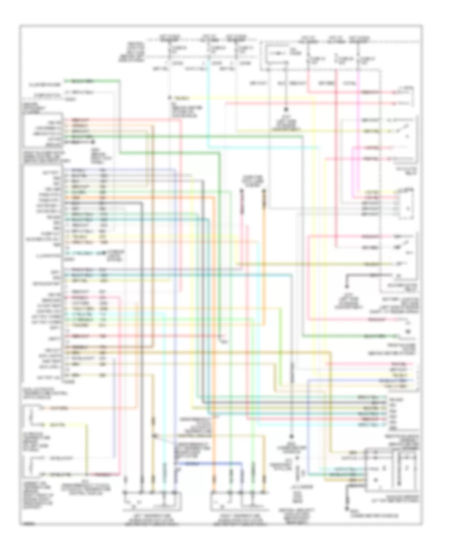
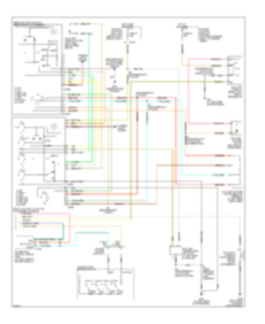
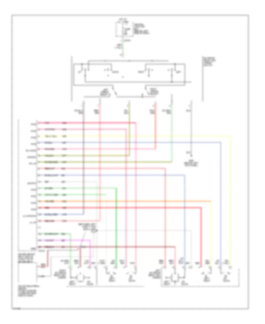
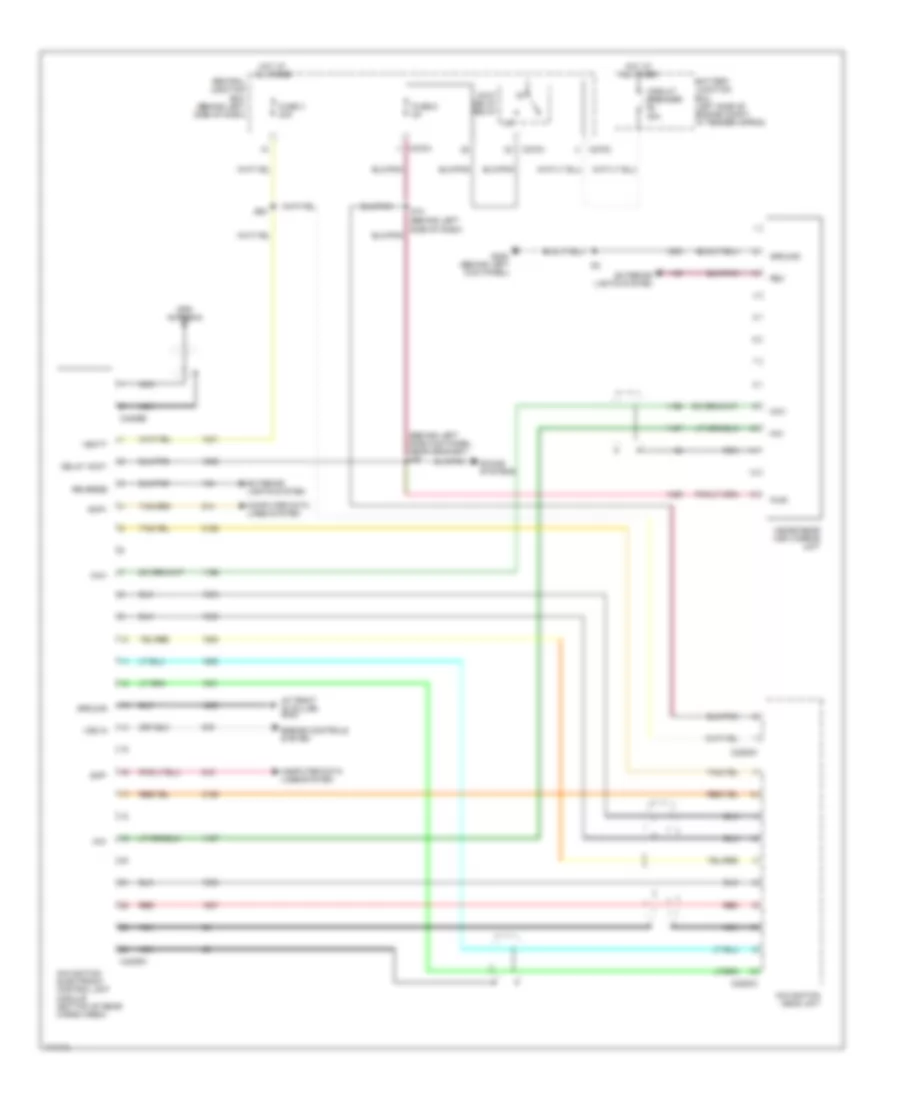
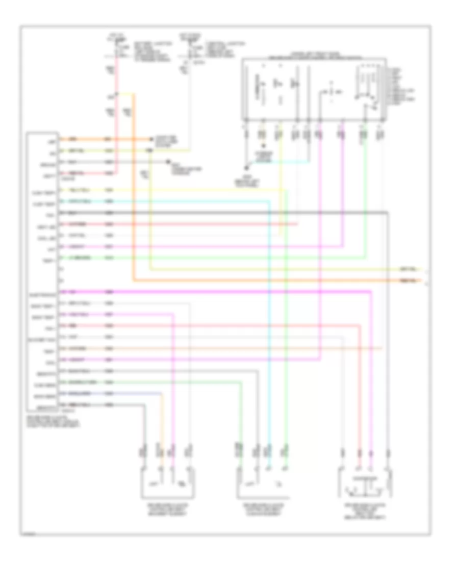
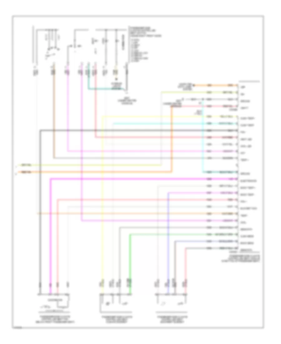
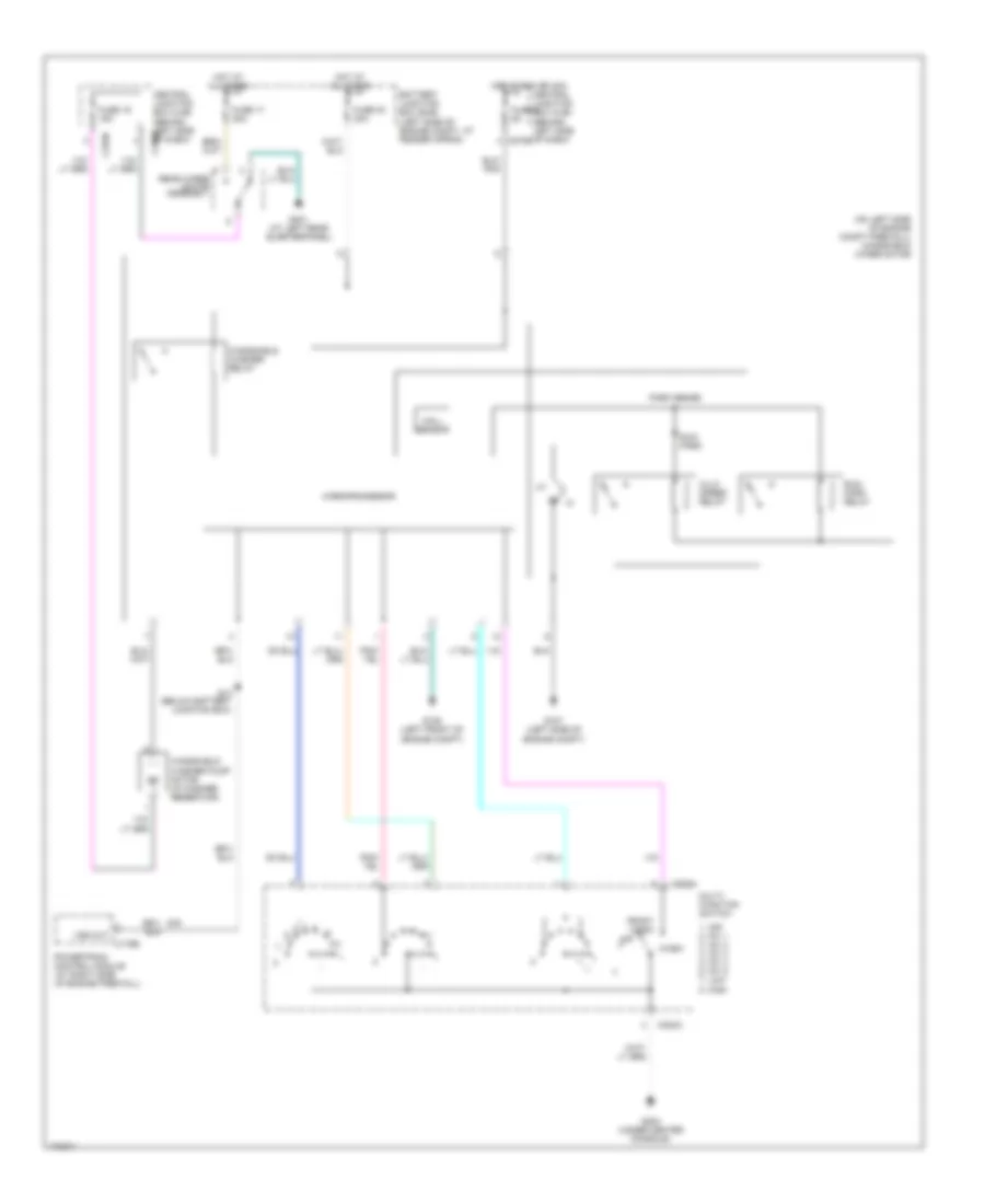
AIR CONDITIONING Automatic A/C Wiring Diagram (1 of 2) for Lincoln Aviator 2003 List of elements for Automatic A/C Wiring Diagram (1 of 2) for Lincoln Aviator 2003: 82 (near breakout to dual automatic temperature control module) (near breakout to temperature blend door actuator) A/c clutch relay A/c diode Act pot +5v Act pot - Act pot wiper Amb temp Ambient air temperature sensor (right front of engine compt, near radiator support) Battery junction box (bjb) (left side of engine compt, at fender apron) Blower ctrl rly Blower motor relay C220a C228a C228b C270b C270d C270f C3008e Central junction box (cjb) (behind left side of dash) Central security module (csm) (behind right rear seat) Cluster power Computer data lines system Control sw Dual automatic temperature control (datc) module Front blower motor (behind center of dash) Front blower motor speed controller (behind center of dash) Fuse 10 10a Fuse 15 10a Fuse 23 5a Fuse 30 5a Fuse 36 40a Fuse 37 15a G107 (left side of engine compartment) G200 (behind right kick panel) G203 (under center console) Gnd Ground Hbr switch in Hot at all times Hot in run or start Ign run/start Illumination In car temp In-vehicle temperature sensor (on left side of dash) Inboard instrument cluster Interior lights system J/c 1 J/c 2 Left temperature blend door actuator (behind right side of dash) Microprocessor Motor Motor drv 1 Motor drv 2 Pass mtr 1 Pass mtr 2 R def out R def switch Remote solenoid assembly (behind center of dash) Right temperature blend door actuator (behind right side of dash) Rs gnd Rs1 Rs2 Rs3 Rs4 Rs5 S13 (near right "d" pillar) S14 (near breakout to dual automatic temperature control module) S24 S4 (behind center of dash on main bundle) Scp + Scp - Sens gnd Sun load l Sun load r Sun load sens Sunload sensor (at top center of dash) Var speed in Vbatt Vbc fb Vbc hbr Vbc out Automatic A/C Wiring Diagram (2 of 2) for Lincoln Aviator 2003 List of elements for Automatic A/C Wiring Diagram (2 of 2) for Lincoln Aviator 2003: 49 (near breakout to auxiliary mode actuator) s3 (near breakout to c3049) s4 (near breakout to four-wheel drive control module) s2 0) off 1) low 2) med low 3) med high 4) high 5) ceiling 6) floor 0) off 1) rear 2) low 3) med low 4) med high 5) ceiling 6) floor A/c clu rly A/c clutch solenoid (right side of engine, on a/c Air bag sliding contact Audio/climate control switch Auxiliary a/c relay (behind left side of rear seats) Auxiliary blower motor (left side of cargo area) Auxiliary blower motor resistor assembly (in left rear cargo area) Auxiliary mode actuator (left side, behind rear seats) Auxiliary temperature actuator (at left rear of vehicle) Battery junction box (bjb) (left side of engine compt, at fender apron) C175b C270f C3198a C3198b C938a C938b Central junction box (cjb) (behind left side of dash) Climate Compressor) Cool Fan dn Fan up Front auxiliary a/c switch (in overhead console) Fuse 10 10a Fuse 33 30a G108 (right rear of engine compartment) G207 (under center console) G401 (at left rear quarterpanel) Gnd Hot at all times Hot in run or start Interior lights system Led Nca Powertrain control module (pcm) (at right side of engine firewall) Rear auxiliary function selector switch assembly S1 (near breakout to c3047) S3 (near breakout to auxiliary mode actuator) S3 (near breakout to c3047) S7 (near breakout to cargo lamp assembly) Sccs Temp dn Temp up Warm
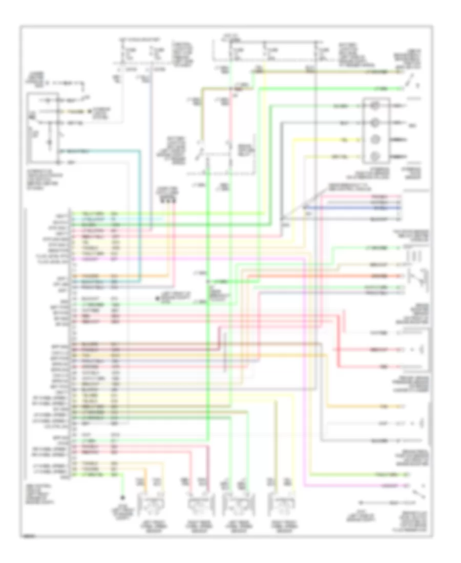
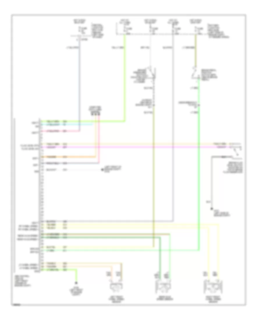
ANTI-LOCK BRAKES Anti-lock Brakes Wiring Diagram, with IVD for Lincoln Aviator 2003 List of elements for Anti-lock Brakes Wiring Diagram, with IVD for Lincoln Aviator 2003: 76 (above brake pedal) brake pedal position (bpp) switch (left front of engine compt) g105 (near breakout to abs control module) (under center console) g203 Abs control module (left front corner of engine compt) Battery junction box (bjb) (left side of engine compt, at fender apron) Bp gnd Bp pwr Bp sig Bpfs nc Bpfs no Bpfs sig Bpp gnd Bpp pwr Bpp sig Brake booster sensor (on front of brake booster) Brake fluid level switch (mounted on top of brake fluid reservoir) Brake pedal position sensor (on front of brake booster) Bst pwm Bst pwr C270b C270d Can 2 hi Can 2 lo Central junction box (cjb) (behind left side of dash) Computer data lines system Fluid level rtn Fluid level sw Fuse 10a Fuse 15a Fuse 30a Fuse 40a G105 (left front of engine compt) G107 (left side of engine compt) Gnd Hot at all times Hot in run or start Interactive vehicle dynamics (ivd) switch (behind center of dash) Interior lights system Iso 9141 Ivd ctrl sw Ivd off Ivd on Left front wheel speed sensor Left rear wheel speed sensor Lf wheel speed + Lf wheel speed - Lr wheel speed + Lr wheel speed - Nca Off led Primary brake pressure sensor (on brake master cylinder) Red Red/ pnk Red/pnk Rf wheel speed + Rf wheel speed - Right front wheel speed sensor Right rear wheel speed sensor Rr wheel speed + Rr wheel speed - S31 S32 Scp + Scp - Sens pwr Steering position sensor (on steering column) Steering rate sensor Str ang 1 Str ang 3 Str ang gnd Sw gnd Tan Vbatt Vpwr Yaw rate sensor (below center console) Anti-lock Brakes Wiring Diagram, without IVD for Lincoln Aviator 2003 List of elements for Anti-lock Brakes Wiring Diagram, without IVD for Lincoln Aviator 2003: 38 (in front center of engine compt) s11 (left front of engine compt) g105 (near breakout to g107) s7 Abs control module (left front corner of engine compt) Battery junction box (bjb) (left side of engine compt, at fender apron) Bpp sw Bps sig Brake fluid level switch (mounted on top of brake fluid reservoir) Brake pedal position switch (bpp) (above brake pedal) Brake pressure switch (mounted on master cylinder) C270b Central junction box (cjb) (behind left side of dash) Computer data lines system Fluid level rtn Fluid level sw Fuse 10a Fuse 15a Fuse 2a Fuse 30a Fuse 40a G105 (left front of engine compt) G107 (left side of engine compt) Gnd Hot at all times Hot in run or start Iso Left front wheel speed sensor Lf wheel speed + Lf wheel speed - Rear axle speed + Rear axle speed - Rear axle speed sensor Rf wheel speed + Rf wheel speed - Right front wheel speed sensor Scp + Scp - Vbatt
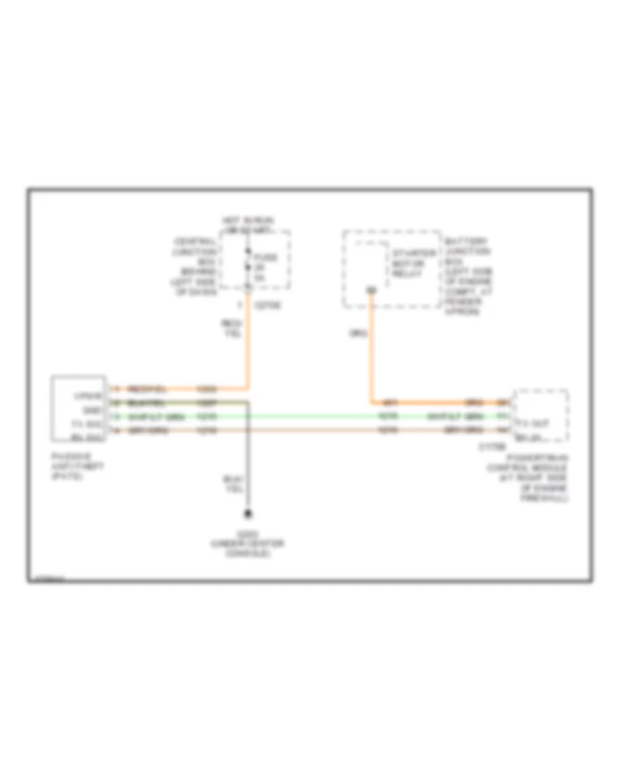
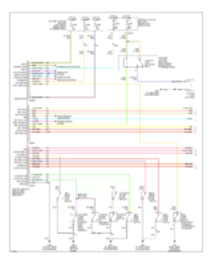
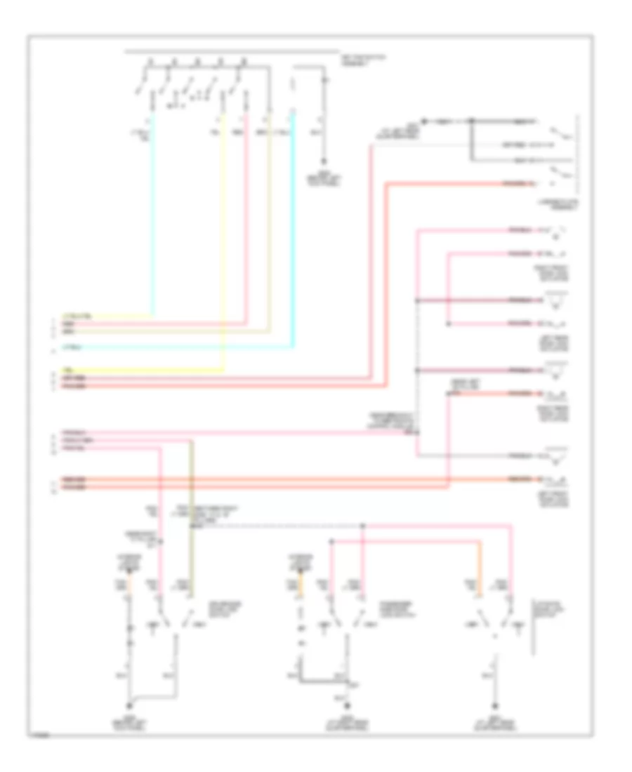
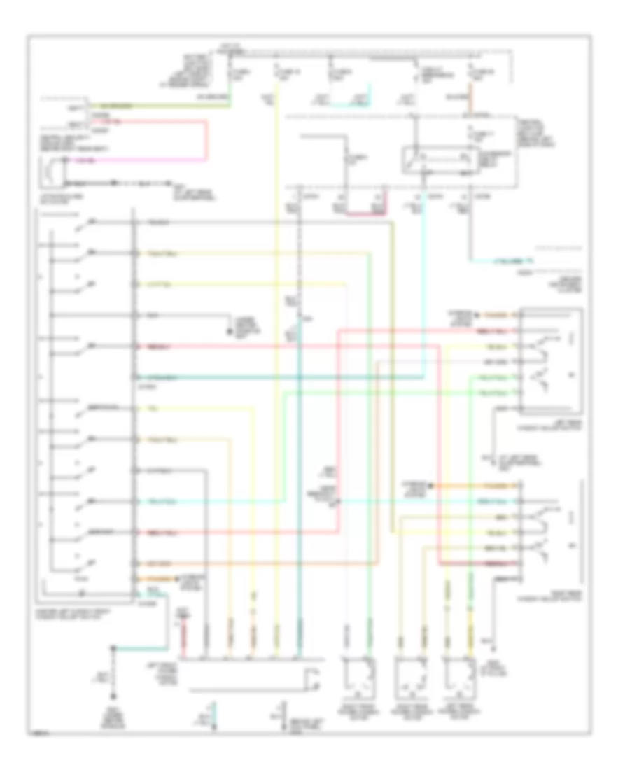
ANTI-THEFT Passive Anti-theft Wiring Diagram for Lincoln Aviator 2003 List of elements for Passive Anti-theft Wiring Diagram for Lincoln Aviator 2003: 16 Battery junction box (left side of engine compt, at fender apron) C175b C270e Central junction box (behind left side of dash) Fuse 5a G203 (under center console) Gnd Hot in run or start Passive anti-theft (pats) Powertrain control module (at right side of engine firewall) Rx in Rx sig Starter motor relay Tx out Tx sig Vpwr Power Door Locks Wiring Diagram (1 of 2) for Lincoln Aviator 2003 List of elements for Power Door Locks Wiring Diagram (1 of 2) for Lincoln Aviator 2003: 69 (near left ``b" pillar) s8 Anti- theft hood switch (right front of engine compartment, on fender) Anti-theft alarm inhibit switch (in driver door, near latch assembly) Anti-theft sw Auxiliary junction box (ajb) (right side of engine compt, at fender apron) Battery junction box (bjb) (left side of engine compt, at fender apron) C270a C3008d C3008e C3008f Central junction box (cjb) (behind left side of dash) Central security module (csm) (behind right rear seat) Computer data lines system Deck rel sw Deck solenoid Dimmer sw Disarm sw Door ajar sw Drv dis sw Exterior lights system Fuse 10a Fuse 15a Fuse 20a Fuse 30a G108 (right rear of engine compartment) G205 (behind left kick panel) G401 (at left rear quarterpanel) G402 (at right rear Gnd Ground Headlamp sw Headlights system Horn sw feed Horns system Hot at all times Key pad a Key pad b Key pad c Key pad illum Key pad rtn Left front door ajar switch Left rear door ajar switch Lf door ajar Liftgate ajar Liftgate ajar switch Liftgate disarm switch (in center of tailgate) Liftgate glass ajar switch Liftgate lock actuator Liftgate lock actuator relay Liftgate sw Lock relay Lr door ajar Marker lamps Power windows system Quarterpanel) Red Rel solenoid Rf door ajar Right front door ajar switch Right rear door ajar switch Rr door ajar S27 S29 Sunload sens Taillamp sw Tan Ubp Unlock relay Vbatt Power Door Locks Wiring Diagram (2 of 2) for Lincoln Aviator 2003 List of elements for Power Door Locks Wiring Diagram (2 of 2) for Lincoln Aviator 2003: 27 (near breakout to restraints control module) s22 (near left ``b" pillar) s15 (near right ``c" pillar) 1/2 3/4 5/6 7/8 9/0 Driver side door lock switch G205 (behind left kick panel) G401 (at left rear quarterpanel) G402 (at right rear quarterpanel) Interior lights system Key pad switch assembly Left front door lock actuator Left rear door lock actuator License plate assembly Liftgate door lock switch Lock Passenger side door lock switch Pnk/ (between right side ``a" & ``b" pillars) s18 Red Right front door lock actuator Right rear door lock actuator S11 S27 Unlk
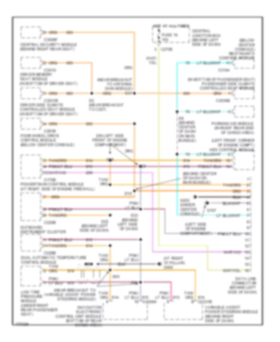
COMPUTER DATA LINES Computer Data Lines Wiring Diagram for Lincoln Aviator 2003 List of elements for Computer Data Lines Wiring Diagram for Lincoln Aviator 2003: 46 (at right "d" pillar) g402 (behind center of dash on main bundle) (below center console) restraints control module (in bottom of passenger seat) passenger side climate controlled seat module (left front corner of engine compt) abs control module (left side of engine compartment) (near breakout to antenna gain module) s31 (near breakout to variable assist power steering module) (on left side front of engine compartment) C175b C220b C228b C270e C281b C3008f C3031b C3036b C310a C341g Central junction box (behind left side of dash) Central security module (behind right rear seat) Data link connector (behind left side of dash) Driver memory seat module (in bottom of driver seat) Driver side climate controlled seat module (in bottom of driver seat) Dual automatic temperature control module Four-wheel drive control module (below center console) Fuse 16 15a G107 G203 (under center console) Hot at all times Low tire pressure module (under right rear passenger seat) Navigation electronic control unit module (bottom of rear cargo area) Nca Outboard instrument cluster Parking aid module (in right rear end of cargo area) Powertrain control module (at right side of engine firewall) S19 S2 (near breakout to c327) S22 (behind left side of dash) S23 (behind left side of dash) S28 S29 S60 S61 S9 (behind center of dash on main bundle) Variable assist power steering module (behind right side of dash)
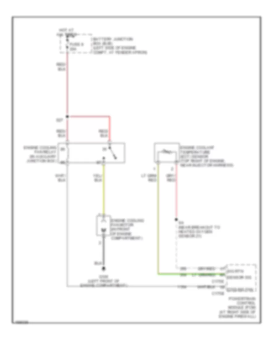
COOLING FAN Cooling Fan Wiring Diagram for Lincoln Aviator 2003 List of elements for Cooling Fan Wiring Diagram for Lincoln Aviator 2003: 15 Battery junction box (bjb) (left side of engine compt, at fender apron) C175b C175e Cooling fan Engine coolant temperature (ect) sensor (top right of engine, near injector harness) Engine cooling fan motor (in front of engine compartment) Engine cooling fan relay (in auxiliary junction box) Fuse 8 20a G105 (left front of engine compartment) Hot at all times Powertrain control module (pcm) (at right side of engine firewall) S27 S4 (near breakout to heated oxygen sensor 21) Sensor sig Sig rtn
CRUISE CONTROL Cruise Control Wiring Diagram for Lincoln Aviator 2003 List of elements for Cruise Control Wiring Diagram for Lincoln Aviator 2003: 39 Air bag sliding contact Battery junction box (bjb) (left side of engine compartment, at fender apron) Bps Bps in Brake pressure switch (mounted on master cylinder) C175b C218a C220b Cancel Computer data lines system Fuse 15a Fuse 2a Hot at all times Hot in run or start J/c 2 (in battery junction box) Nca Off Outboard instrument cluster Powertrain control module (pcm) (at right side of engine firewall) Redundant pedal switch (under left side dash panel) Res S11 (in front center of engine compartment) Scc Sccs Scm a Scm b Scm c Scp bus+ Scp bus- Scp+ Scp- Set+ Set- Speed control actuator (right side of engine compartment, on fender) Speed control switch Speed ctrl sw gnd Vbatt W/ ivd W/o ivd
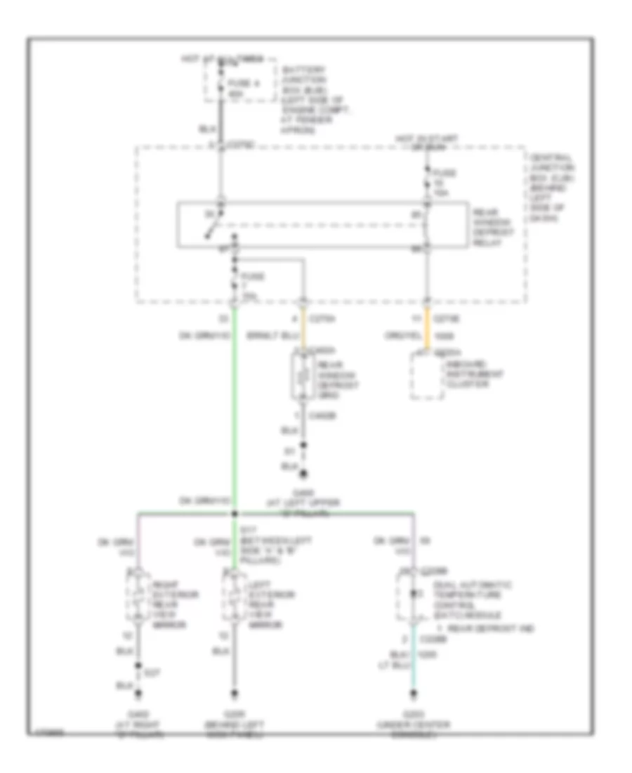
DEFOGGERS Defoggers Wiring Diagram for Lincoln Aviator 2003 List of elements for Defoggers Wiring Diagram for Lincoln Aviator 2003: 27 Battery junction box (bjb) (left side of engine compt, at fender apron) C220a C228b C270a C270c C270e C402a C402b Central junction box (cjb) (behind left side of dash) Dual automatic temperature control (datc) module Fuse 10a Fuse 15a Fuse 4 40a G203 (under center console) G205 (behind left kick panel) G400 (at left upper ``d" pillar) G402 (at right ``d" pillar) Hot at all times Hot in start or run Inboard instrument cluster Left exterior rear view mirror Rear defrost ind Rear window defrost grid Rear window defrost relay Right exterior rear view mirror S27 Side "a" & "b" pillars)
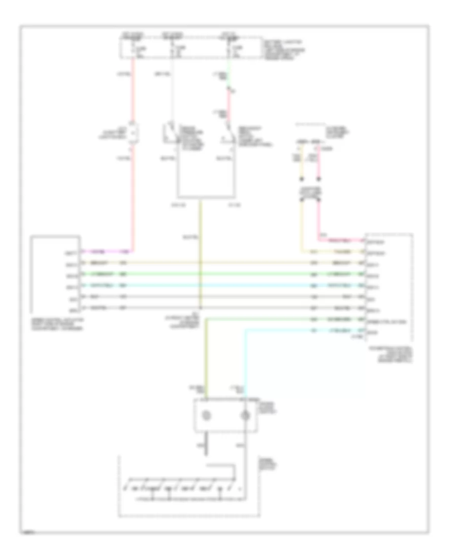
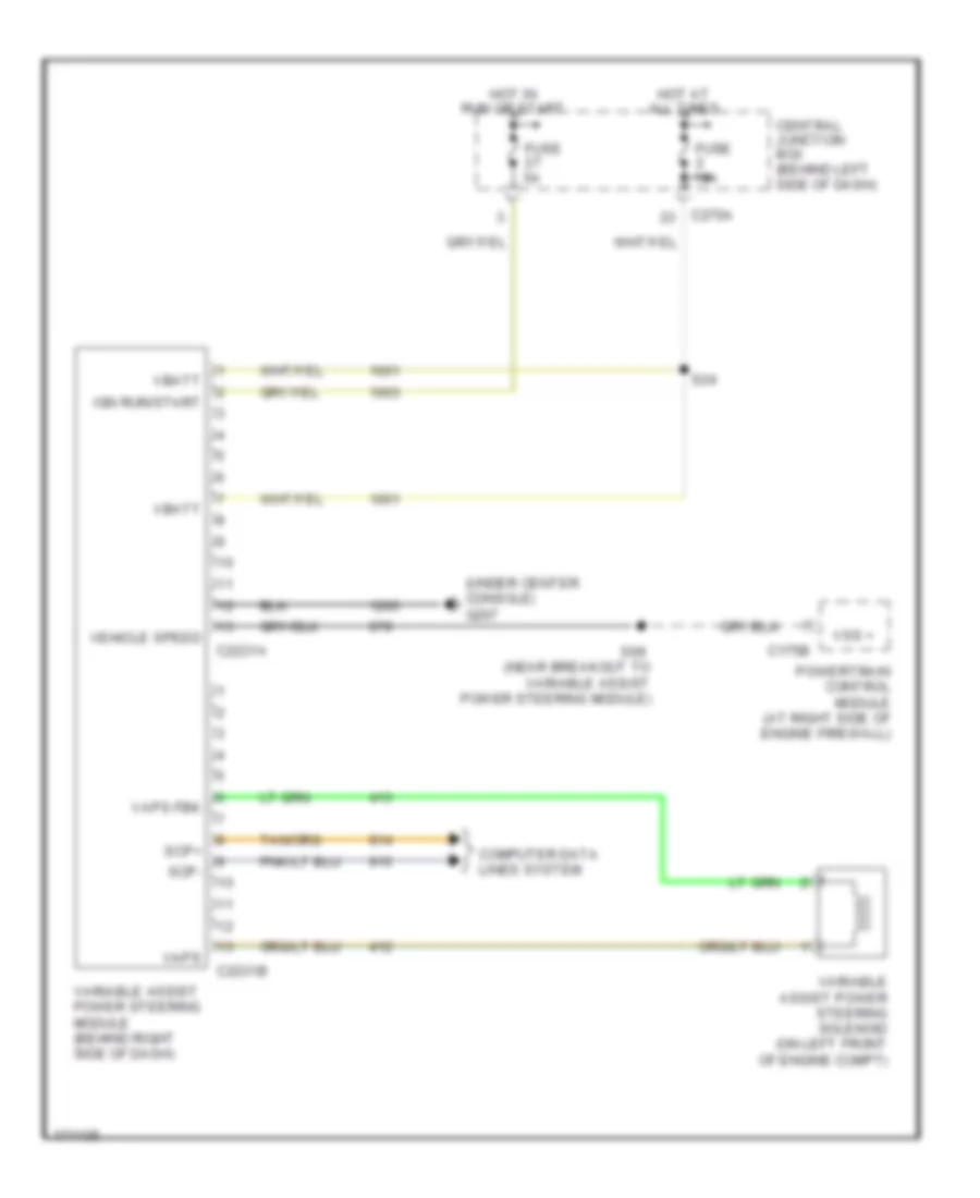
ELECTRONIC POWER STEERING Electronic Power Steering Wiring Diagram for Lincoln Aviator 2003 List of elements for Electronic Power Steering Wiring Diagram for Lincoln Aviator 2003: 24 (under center console) g207 C175b C2231a C2231b C270a Central junction box (behind left side of dash) Computer data lines system Fuse 10a Fuse 5a Hot at all times Hot in run or start Ign run/start Powertrain control module (at right side of engine firewall) S24 S69 (near breakout to variable assist power steering module) Scp+ Scp- Vaps Vaps fbk Variable assist power steering module (behind right side of dash) Variable assist power steering solenoid (on left front of engine compt) Vbatt Vehicle speed Vss +
ENGINE PERFORMANCE
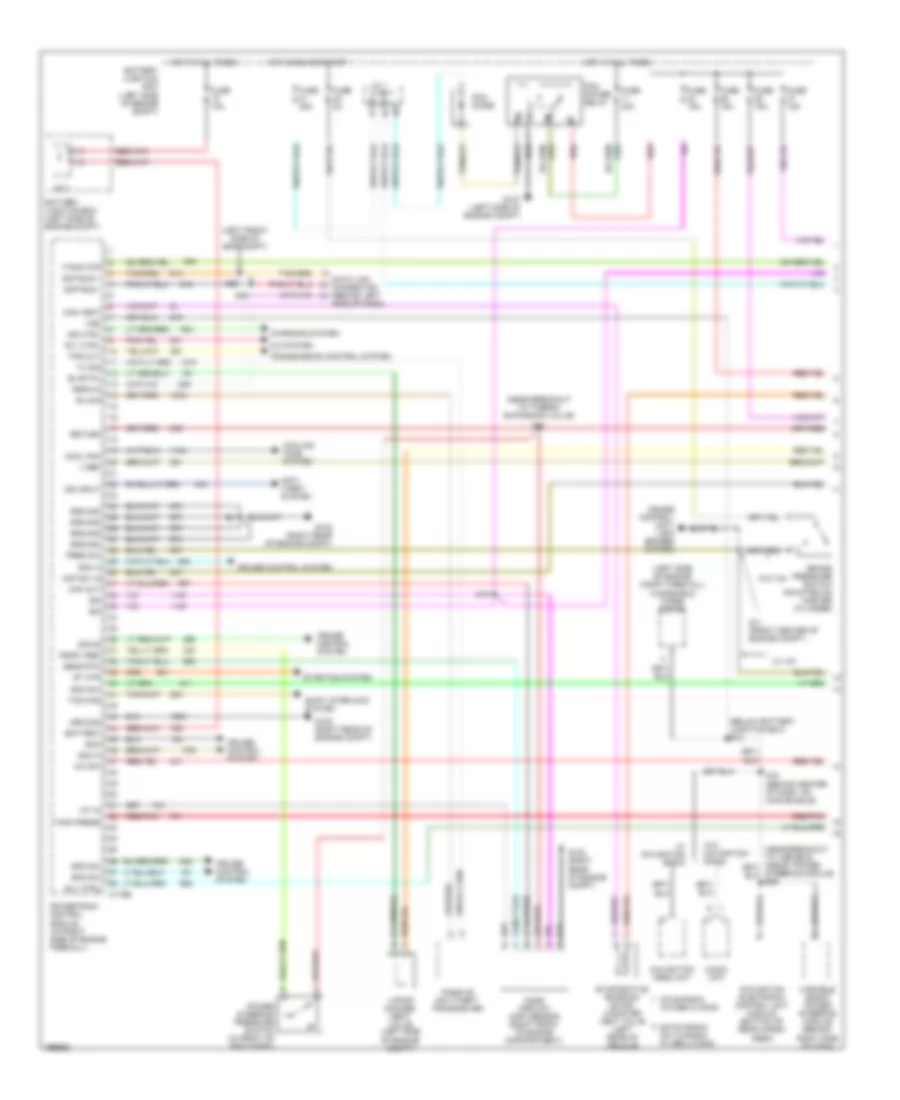
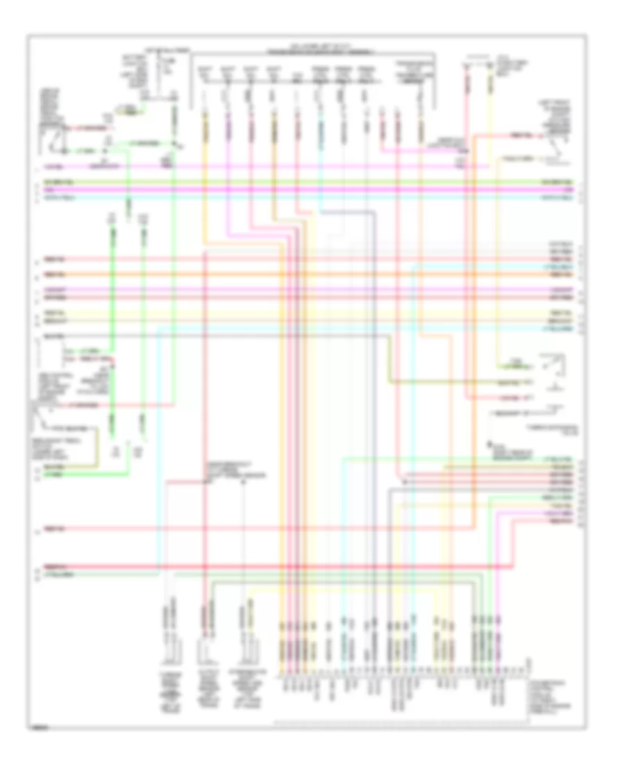
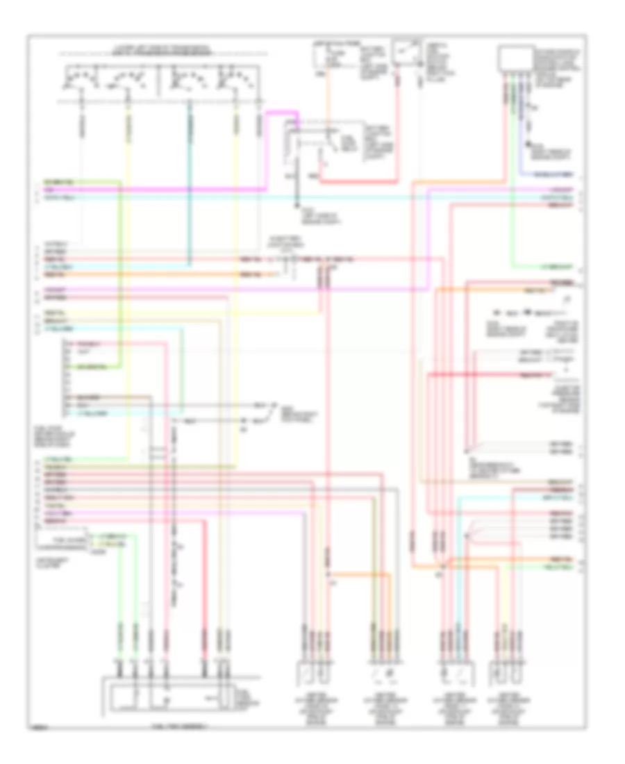
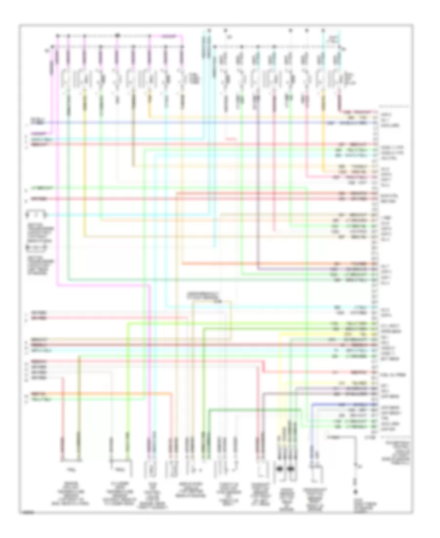
4.6L 4.6L, Engine Performance Wiring Diagram (1 of 4) for Lincoln Aviator 2003 List of elements for 4.6L, Engine Performance Wiring Diagram (1 of 4) for Lincoln Aviator 2003: 89 (below battery junction box) s12 (left front side of eng compt) (left side of engine compt firewall) windshield wiper motor (near breakout to thermo expansion valve) A/c sw A/c system Acp sw in Anti- theft system Audio unit Battery Battery junction box (left side of engine compt) Boo sw Brake pressure switch (mounted on master cylinder) C175b Can vent Cd x6 radio w/o gen 2 conn Charging system Cool fan Cooling fans system Cruise control system Cruise control/ anti- lock brakes system Data link connector (behind left Dm100 radio/ cd x 6 radio w/ gen 2 conn Evap pu Evaporative emission (evap) canister vent valve (left rear of vehicle) F pmp mtr Feps in Fuse 10a Fuse 15a Fuse 25a Fuse 2a Fuse 40a G107 (left side of engine compt) G108 (right rear of engine compt) Ground Hot at all times Hot in run or start Iat in Ign Ind ctrl Ind input J/c 1 Maf out Mass airflow (maf) sensor (right front of engine compartment) Navigation electronic control unit module (bottom of rear cargo area) Navigation head unit Passive anti-theft transceiver Pcm diode Pcm power relay Power steering pressure switch (in front of eng compt) Powertrain control module (at right side of engine firewall) Pres sw Psps vref Red Red/pnk Return Rly ctrl Rx sig S10 S11 (front center of engine compt) S18 (behind center of dash, on main bundle) S19 S28 S29 Scc Scm a Scm b Scm c Scp bus + Scp bus - Sens rtn Shift interlock system Side of dash) Spd sw St mtr Starting system Tank press Tcs ocs Tps out Transmission control system Tx sig V ref Vapor manage- ment valve (left side of engine compt) Variable assist power steering module (behind right side of dash) Vss W/ ivd W/ navigation radio W/o ivd W/o navigation radio 4.6L, Engine Performance Wiring Diagram (2 of 4) for Lincoln Aviator 2003 List of elements for 4.6L, Engine Performance Wiring Diagram (2 of 4) for Lincoln Aviator 2003: 52 (above brake pedal) brake pedal position switch (left front of engine compt) a/c high pressure switch (near aux junction box) s4 (near breakout to turbine shaft speed sensor) s2 (on lower left of a/t) transmission solenoid body assembly Abs control module (left front of engine compt) Battery junction box (left side of eng compt) C175t Epc sol Fuse 15a G108 (right rear of engine compt) H2os 12 htr H2os 12 in H2os 22 htr H2os 22 in Hot at all times Intermediate shaft speed (iss) sensor (top left side of trans) Iss J/c 2 (in battery junction box) Oss Output shaft speed sensor (left rear of trans) Pcs b Pcs c Powertrain control module (at right side of engine firewall) Press ctrl sol a Press ctrl sol b Press ctrl sol c Red/pnk Redundant pedal switch (under left side of dash) S21 (near breakout to low pitch horn) S7 (near g107) Shift sol a Shift sol b Shift sol c Shift sol d Sig rtn Ss a Ss b Ss c Ss d Tcc sol Tft Thermo expansion valve Tr1 Tr2 Tr3a Tr4 Transmission fluid temperature sensor Tss Turbine shaft speed (tss) sensor (top left of trans) W/ ivd W/o ivd 4.6L, Engine Performance Wiring Diagram (3 of 4) for Lincoln Aviator 2003 List of elements for 4.6L, Engine Performance Wiring Diagram (3 of 4) for Lincoln Aviator 2003: 29 (in battery junction box) j/c 2 (lower left side of transmission) digital transmission range sensor Battery junction box (left side of engine compt) C220b Fuel guage Fuel pump driver module (behind right side of dash) Fuel pump relay Fuel tank assembly Fuel tank sending unit Fuse 20a G107 (left side of engine compt) G108 (right rear of engine compt) G202 (behind right kick panel) Heated oxygen sensor (ho2s) 11 (on exhaust pipe of engine) Heated oxygen sensor (ho2s) 12 (on exhaust pipe of engine) Heated oxygen sensor (ho2s) 21 (on exhaust pipe of engine) Heated oxygen sensor (ho2s) 22 (on exhaust pipe of engine) Hot at all times Inertia fuel shutoff switch (behind right kick pillar) Injector pressure sensor (top right side of engine) Instrument cluster Intake manifold communication control-long runner control module (on top rear of engine) Microprocessor N r Nca Positive crankcase ventilation heater Red Red/pnk S4 (near breakout to heated oxygen sensor 21) 4.6L, Engine Performance Wiring Diagram (4 of 4) for Lincoln Aviator 2003 List of elements for 4.6L, Engine Performance Wiring Diagram (4 of 4) for Lincoln Aviator 2003: 56 (near breakout to kock sensor) s1 C175e Camshaft position sensor (top front of left cyl head) Ckp sens + Ckp sens - Cmp sens Coil on plug Cop 1 Cop 2 Cop 3 Cop 4 Cop 5 Cop 6 Cop 7 Cop 8 Crankshaft position sensor (right front of engine) Cyl input Cylinder head temperature sensor (on right rear of cylinder head) Dfpe sens Ect sens Egr system module (top center rear of engine) Engine coolant temperature sensor (top right of eng, near inj harn) Evr ctrl Fuel inj pres Fuel injec- tors G108 (right rear of engine compt) Ho2s 11 Ho2s 11 htr Ho2s 21 Ho2s 21 htr Iac ctrl Idle air control valve (top of engine, near throttle body) Ignition transformer capacitor 1 (left rear of engine) Ignition transformer capacitor 2 (top right rear of eng) Imcc-lsrc Inj 1 Inj 2 Inj 3 Inj 4 Inj 5 Inj 6 Inj 7 Inj 8 Knock sensor (on top rear of engine) Ks 1 Ks 2 Map sig Nca Powertrain control module (at right side of engine firewall) Red/pnk Return Tan Tan/red Throttle position (tps) sensor (on throttle body) Tps V ref
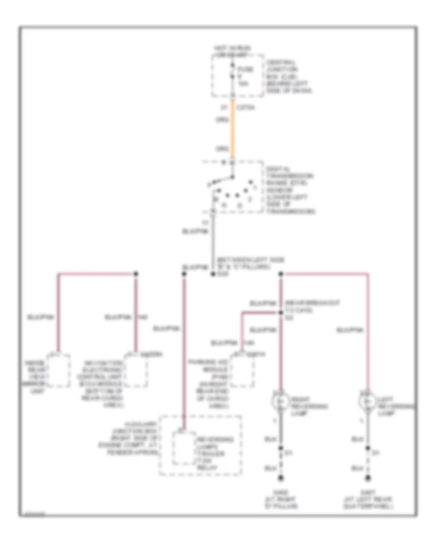
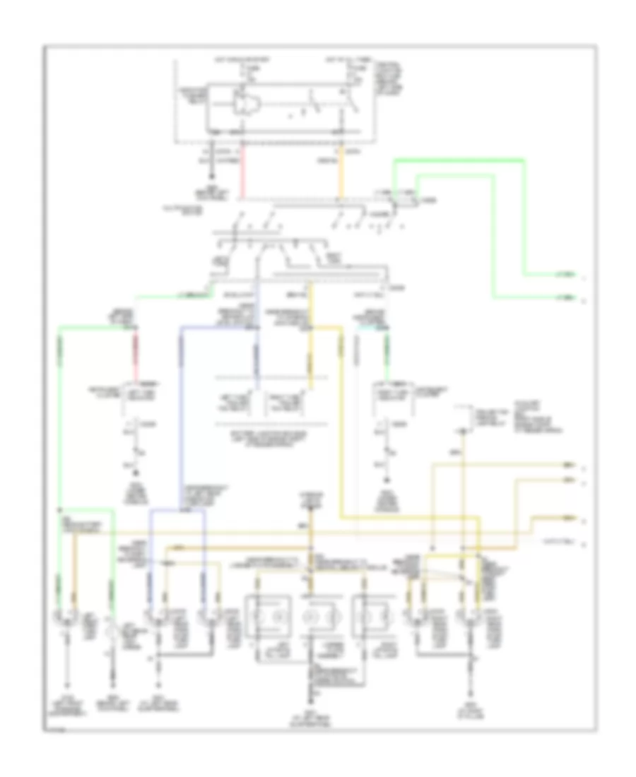
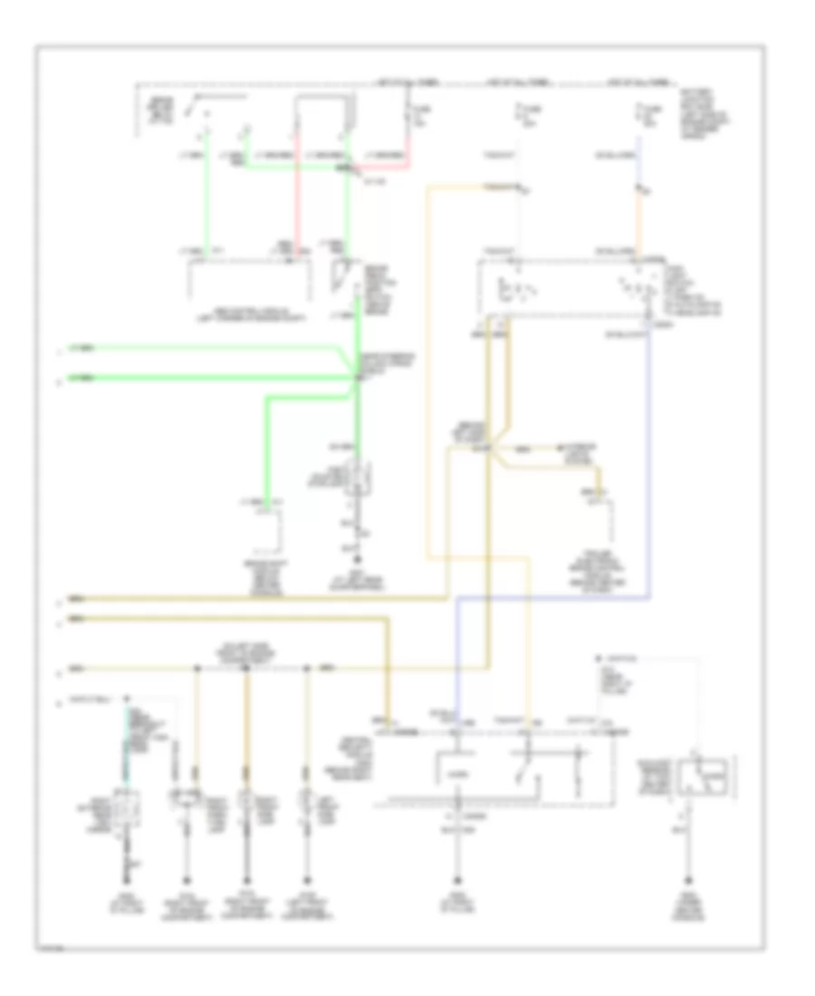
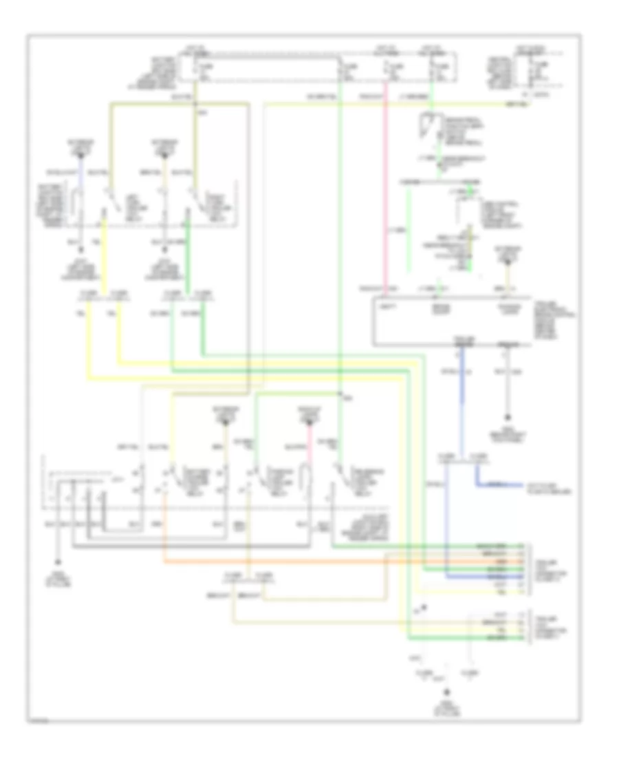
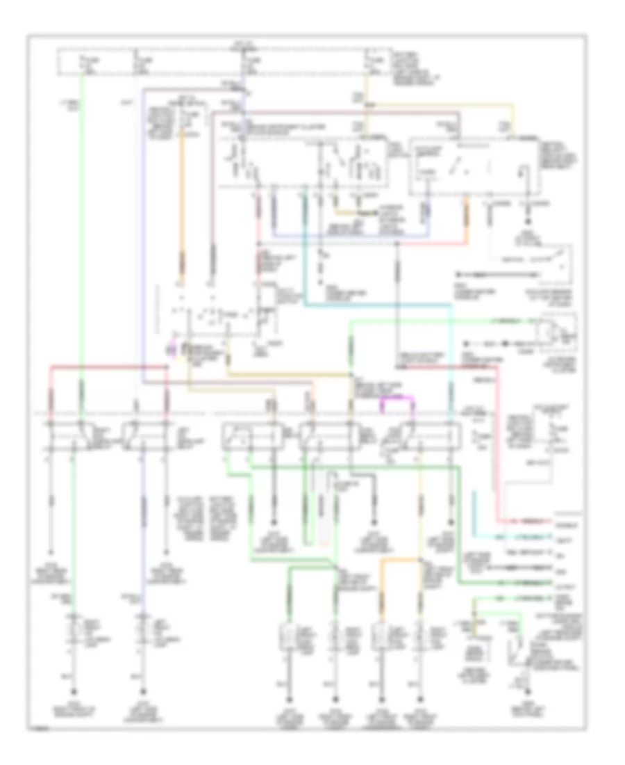
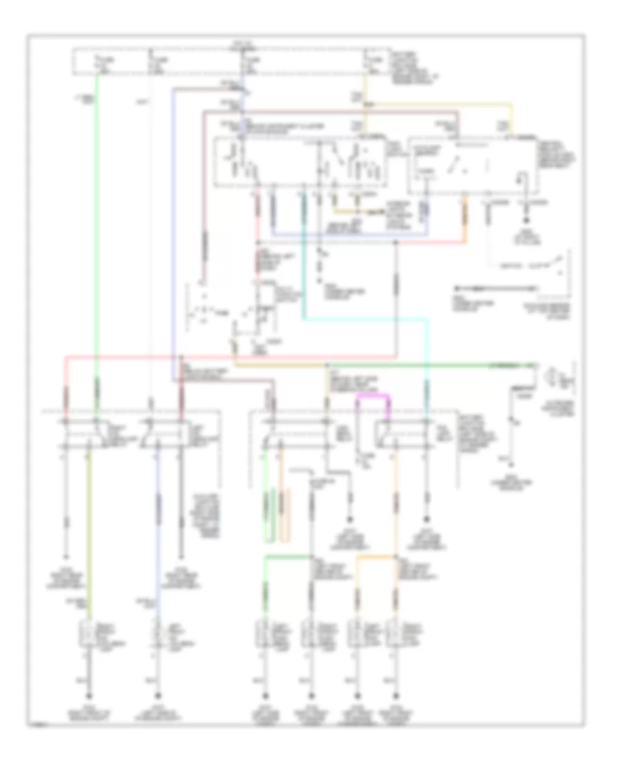
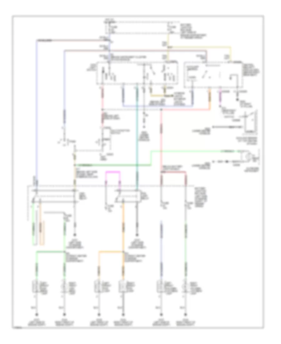
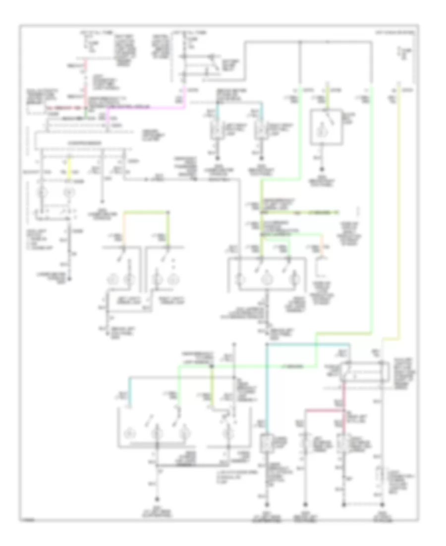
EXTERIOR LIGHTS Back-up Lamps Wiring Diagram for Lincoln Aviator 2003 List of elements for Back-up Lamps Wiring Diagram for Lincoln Aviator 2003: 18 (near breakout to c410) s2 Auxiliary junction box (right side of engine compt, at fender apron) C270a C4014 C4209a Central junction box (cjb) (behind left side of dash) Digital transmission range (dtr) sensor (lower left side of transmission) Fuse 10a G401 (at left rear quaterpanel) G402 (at right "d" pillar) Hot in run or start Inside rear view mirror unit Left reversing lamp Navigation electronic control unit (ecu) module (bottom of rear cargo area) Parking aid module (pam) (in right rear end of cargo area) Reversing lamps trailer tow relay Right reversing lamp S20 Exterior Lamps Wiring Diagram (1 of 2) for Lincoln Aviator 2003 List of elements for Exterior Lamps Wiring Diagram (1 of 2) for Lincoln Aviator 2003: 51 (behind instrument cluster) s16 (behind left side of dash) s10 (near breakout to antenna gain module) s30 (near breakout to brake fluid level switch) s34 (near breakout to left rear park/stop/ turn lamp) s2 (near breakout to license plate assembly) (near breakout to right reversing lamp) 87a Auxiliary junction box (right side of engine compt, at fender apron) Battery junction box (bjb) (left side of engine compt, at fender apron) C202b C220a C220b C270a C270h C4032 C4034 C4035 C4036 Central junction box (cjb) (behind left side of dash) Fuse 10a Fuse 15a G105 (left front of engine compartment) G203 (under center console) G205 (behind left kick panel) G401 (at left rear quarterpanel) G402 (at right "d" pillar) Hazard Hot at all times Hot in run or start Indicator flasher relay Instrument cluster Interior lights system Left exterior rear view mirror Left front park/ turn lamp Left liftgate tail lamp Left rear park/ stop/ turn lamp Left turn Left turn indicator Left turn trailer tow relay License plate assembly Multifunction switch Right liftgate tail lamp Right rear park/ stop/ turn lamp Right turn Right turn indicator Right turn trailer tow relay S24 (near battery junction box) S4 (near breakout to right rear park/ stop/ turn lamp) To liftgate disarm switch) Trailer tow parking lamp relay Exterior Lamps Wiring Diagram (2 of 2) for Lincoln Aviator 2003 List of elements for Exterior Lamps Wiring Diagram (2 of 2) for Lincoln Aviator 2003: 33 (behind left side of dash) (near steering column wiring shield) s11 (on left side front of engine compartment) s9 Abs control module (left corner of engine compt) Battery junction box (bjb) (left side of engine compt, at fender apron) Brake pedal position (bpp) switch (above brake Brake shift module (below center console) C205a C3008d C3008e Central security module (csm) (behind right rear seat) Fuse 15a Fuse 20a G104 (right front of engine compartment) G105 (left front of engine compartment) G203 (under center console) G401 (at left rear quarterpanel) G402 (at right "d" pillar) High mounted stoplamp Hot at all times Interior lights system Left front side lamp Main light switch 0) off 1) park on 5) autolamp on 7) headlamp on Micro Right exterior rear view mirror Right front park/ turn lamp Right front side lamp S12 S13 (near right "d" pillar) S23 (near breakout to left front high beam lamp) Sunload sensor (at top center of dash) Trailer electronic brake control module (behind center of dash) W/ ivd Trailer Tow Wiring Diagram for Lincoln Aviator 2003 List of elements for Trailer Tow Wiring Diagram for Lincoln Aviator 2003: 40 (cut flush plastic sealed) (near breakout to low pitch horn) s21 Abs control module (left front corner of engine compt) Auxiliary junction box (right side of engine compt, at fender apron) Back-up lamps circuit Battery charge trailer tow relay Battery junction box (bjb) (left side of engine compt, at fender apron) Brake on/off Brake pedal position (bpp) switch (above brake pedal) C270a Central junction box (cjb) (behind left side of dash) Class ii Class iii Exterior lights circuit Fuse 15a Fuse 20a Fuse 30a Fuse 40a Fuse 5a G107 (left side of engine compartment) G202 (behind right kick panel) G402 (at right "d" pillar) Ground Hot at all times Hot in run or start J/c 4 Left turn trailer tow relay Parking lamp trailer tow relay Reversing lamps trailer tow relay Right turn trailer tow relay Running lamps S32 S44 Trailer brake Trailer electronic brake control module (behind center of dash) Trailer tow connector (class ii) Trailer tow connector (class iii) Vbatt W/ ivd W/o ivd
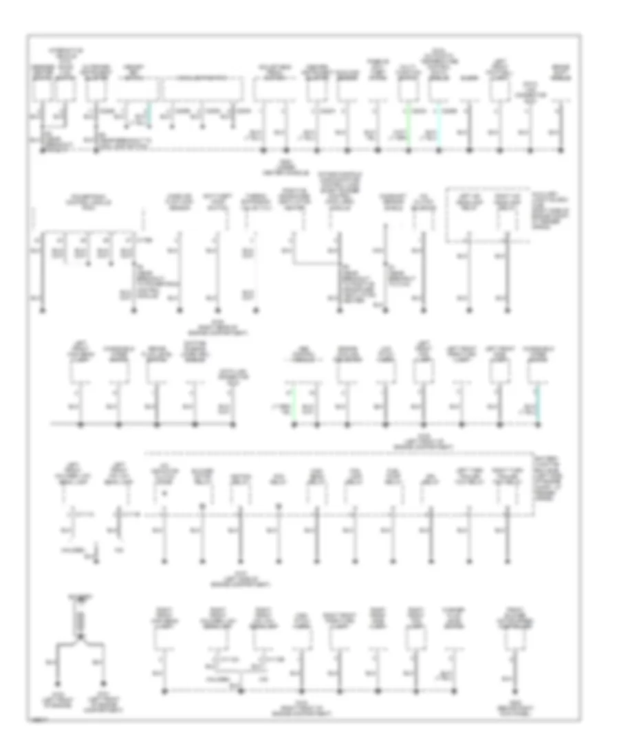
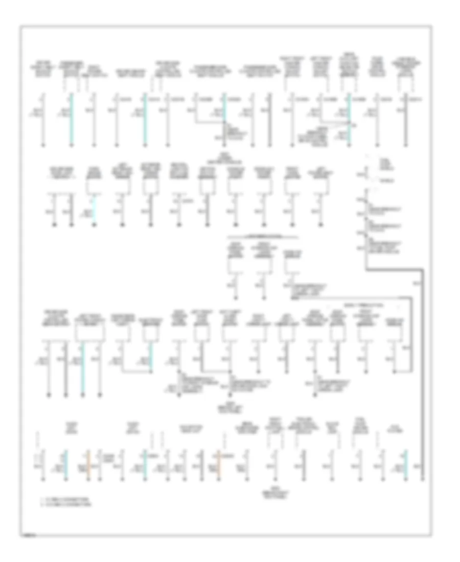
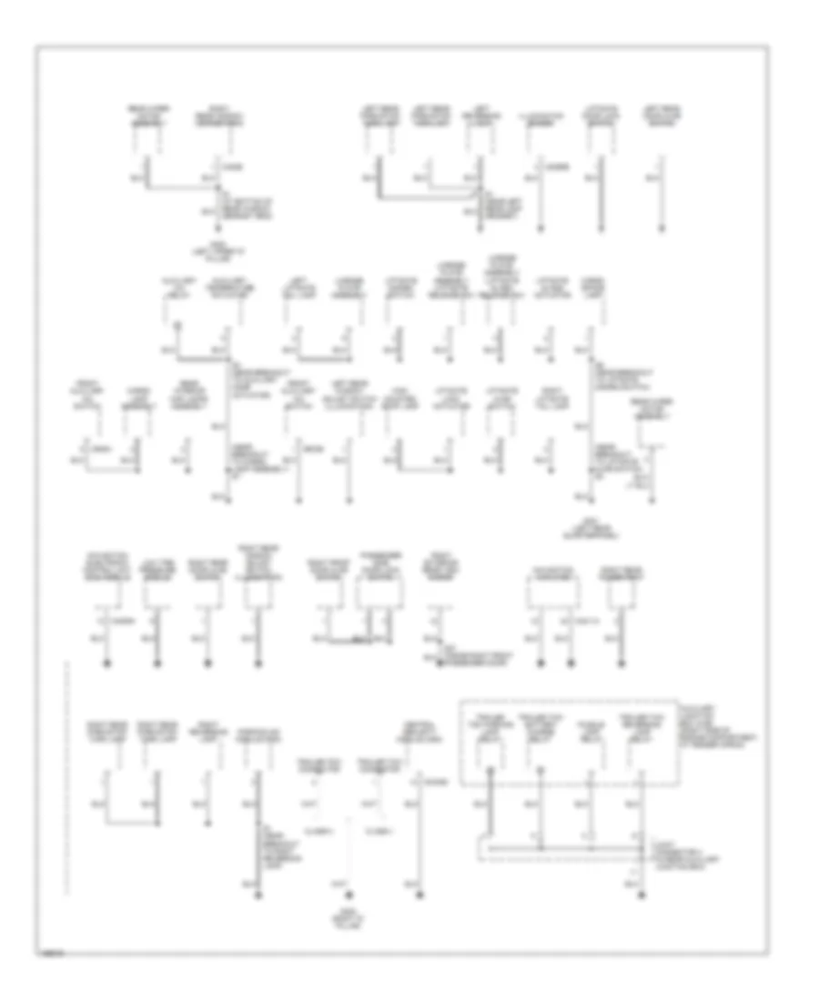
GROUND DISTRIBUTION Ground Distribution Wiring Diagram (1 of 3) for Lincoln Aviator 2003 List of elements for Ground Distribution Wiring Diagram (1 of 3) for Lincoln Aviator 2003: 86 A/c clutch solenoid A/c indicator clutch diode Abs control module Adjustable pedal switch Anti-theft hood switch Auxiliary junction box (ajb) (right side of engine compt, at fender apron) Battery Battery junction box (bjb) (left side of engine compt, at fender apron) Blower motor relay Brake fluid level switch Brake shift module Breakout to c211) C1111a C1111b C1112a C1112b C175b C202a C205a C205b C205c C220a C220b C228b Camshaft sensor shield Clock Data link connector (dlc) Daytime running lamps (drl) module Drl relay Dual automatic temperature control (datc) module Engine cooling fan motor Fog lamp relay Front blower motor speed controller Fuel pump relay G100 (left front of engine) G101 (left front of engine compartment) G104 (right front of engine compartment) G105 (left front of engine compartment) G107 (left side of engine compartment) G108 (right rear of engine compartment) G200 (behind right kick panel) G203 (under center console) Halogen Hid High beam relay High pitch horn Ignition relay Inboard instrument cluster Intake manifold communication control-long short runner control (imcc-lsrc) module Interactive vehicle dyn- amics (ivd) switch Left front fog lamp Left front footwell lamp Left front halogen low beam lamp Left front hid low beam lamp Left front high beam lamp Left front park/turn lamp Left front side lamp Left hid headlamp relay Left turn trailer tow relay Low pitch horn Main light switch Mass air flow (maf) sensor Memory set switch Message center switch Module) Multi- function switch Nca Outboard instrument cluster Passive anti- theft (pats) Pcm relay Positive crankcase ventilation heater Powertrain control module (pcm) Right front fog lamp Right front halogen low beam lamp Right front hid low beam lamp Right front high beam lamp Right front park/turn lamp Right front side lamp Right hid headlamp relay Right turn trailer tow relay S5 (near breakout to main lamp switch) S7 (near breakout to c144) Sunload sensor Thermo expansion valve (txv) Washer fluid level switch Windshield wiper motor Ground Distribution Wiring Diagram (2 of 3) for Lincoln Aviator 2003 List of elements for Ground Distribution Wiring Diagram (2 of 3) for Lincoln Aviator 2003: 73 (early production) (late production) (near breakout to four wheel drive control module) Actuator) Anti-theft alarm inhibit switch Audio unit (cdx6) Audio unit (dm100) C2231a C2253c C240b c290a C270a C281b C290a C3031b C3036a C3036b C3193a C3198b C341e C341g Central junction box (cjb) (flasher) Console 2 power point Console power point Driver memory seat module Driver module) Driver safety belt buckle switch Driver side climate controlled seat module Driver side climate controlled seat switch Driver side door lock switch Dvd player Electronic compass Exterior rear view mirror switch Four- wheel drive control module Front cigar lighter Front interior map lamps assembly Fuel pump driver module Fuel pump shield G202 (behind right kick panel) G205 (behind left kick panel) G207 (under center console) Glove box lamp Homelink module Inside rear view mirror unit Keypad switch assembly Left exterior rear view mirror Left front door ajar switch Left front master window adjust switch Left front power window motor Left power seat switch Left vanity mirror lamp Navigation head unit Nca Park brake switch Passenger safety belt buckle switch Passenger side climate controlled seat module Passenger side climate controlled seat switch Rear auxiliary function selector switch assembly Rear subwoofer amplifier Right front footwell lamp Right front master window adjust switch Right power seat switch Right vanity mirror lamp Roof opening panel motor assembly Roof opening panel switch S1 (near breakout to c315) S1 (near breakout to left vanity mirror lamp) S2 (near breakout to c313) S3 (near breakout to front interior map lamps assembly) Shield Trailer electronic brake control module Variable assist power steering (vaps) module W/ gen 2 connectors W/o gen 2 connectors Ground Distribution Wiring Diagram (3 of 3) for Lincoln Aviator 2003 List of elements for Ground Distribution Wiring Diagram (3 of 3) for Lincoln Aviator 2003: 64 (near breakout to cargo lamp assembly) s7 (near breakout to liftgate ajar switch) s3 Auxiliary a/c relay Auxiliary junction box (ajb) (right side of engine compartment, at fender apron) Auxiliary temperature actuator C2065b C3008d C402b C4209a C4211a C938a C938b Cargo lamp assembly Cargo space lamp Central security module (csm) Class ii Class iii Front auxiliary a/c switch G400 (left upper "d" pillar) G401 (left rear quarterpanel) G402 (right "d" pillar) High mounted stop lamp Illumination dimmer Joint connector 4 (in rear auxiliary junction box) Left liftgate tail lamp Left rear door ajar switch Left rear park/stop/ turn lamp Left rear window adjust switch (illumination) Left reversing lamp License plate assembly License plate assembly (liftgate glass release sw) License plate assembly (liftgate release sw) Liftgate ajar switch Liftgate disarm switch Liftgate door lock switch Liftgate glass actuator Liftgate lock actuator Low tire pressure module Navigation amplifier Navigation electronic control unit (ecu) module Parking aid module (pam) Passenger door) Passenger side door lock switch Puddle lamp relay Rear interior map lamps assembly Rear wiper motor assembly Right exterior rear view mirror Right front door ajar switch Right liftgate tail lamp Right rear door ajar switch Right rear park/stop/ turn lamp Right rear power point Right rear window adjust switch (illumination) Right rear window defrost grid Right reversing lamp S1 (at bottom of rear window defrost grid) S1 (near breakout to right reversing lamp) S1 (near left rear lamp grommet) S3 (near breakout to auxiliary mode actuator) S6 (near breakout to liftgate disarm switch) Trailer tow battery charge relay Trailer tow connector Trailer tow parking lamp relay Trailer tow reversing lamp relay
HEADLIGHTS Headlights Wiring Diagram, with DRL for Lincoln Aviator 2003 List of elements for Headlights Wiring Diagram, with DRL for Lincoln Aviator 2003: 70 (behind instrument cluster) s26 (below battery junction box) s8 (left side of engine compt) g107 (not used) Auto Autolamp switch Auxiliary junction box (ajb) (right side of engine compt, at fender apron) Battery junction box (bjb) (left side of engine compt, at fender apron) C202c C205a C220a C220b C270c C270h C3008d C3008e Central junction box (cjb) (behind left side of dash) Central security module (csm) (behind right rear seat) Daytime running lamps (drl) module (left rear side of engine compt) Disable Drl relay Exterior lights systems Fog lamp relay Fuse 15a Fuse 20a Fuse 46 20a Fuse 5a G104 (right front of engine compt) G105 (left front of engine compartment) G107 (left side of engine compartment) G107 (left side of engine compt) G108 (right rear of engine compartment) G203 (under center console) G205 (behind left kick panel) G402 (at right ``d" pillar) Gnd Head Hi beam ind High beam relay Hot at all times Hot in start or run Ign Inboard instrument cluster Interior lights, Left front fog lamp Left front hid low beam lamp Left front high beam lamp Left hid headlamp relay Main light switch Micro Multi- function switch Off Outboard instrument cluster Output Park Park brake sig Park brake signal Park brake switch (under driver side dash panel) Pass Right front fog lamp Right front hid low beam lamp Right front high beam lamp Right hid headlamp relay S12 (behind left side of dash) S17 (behind left side of dash, near steering column) S20 (left front center of engine compt) S21 (behind left side of dash) S33 (left front center of engine compt) Sunload sensor (at top center of dash) Vbatt Headlights Wiring Diagram, without DRL, with High Intensity Headlights for Lincoln Aviator 2003 List of elements for Headlights Wiring Diagram, without DRL, with High Intensity Headlights for Lincoln Aviator 2003: 51 (not used) Auto Autolamp switch Auxiliary junction box (ajb) (right side of engine compt, at fender apron) Battery junction box (bjb) (left side of engine compt, at fender apron) C202c C205a C220b C3008d C3008e Central security module (csm) (behind right rear seat) Exterior lights systems Fog lamp relay Fuse 15a Fuse 20a Fuse 46 20a G104 (right front of engine compt) G105 (left front of engine compartment) G107 (left side of engine compartment) G107 (left side of engine compt) G107 (left side of of engine compt) G108 (right rear of engine compartment) G203 (under center console) G402 (at right ``d" pillar) Head Hi beam ind High beam relay Hot at all times Interior lights, Left front fog lamp Left front hid low beam lamp Left front high beam lamp Left hid headlamp relay Main light switch Micro Multi- function switch Off Outboard instrument cluster Park Pass Right front fog lamp Right front hid low beam lamp Right front high beam lamp Right hid headlamp relay S12 (behind left side of dash) S17 (behind left side of dash, near steering column) S20 (left front center of engine compt) S21 (behind left side of dash) S33 (left front center of engine compt) S8 (below battery junction box) Sunload sensor (at top center of dash) Headlights Wiring Diagram, without DRL, without High Intensity Headlights for Lincoln Aviator 2003 List of elements for Headlights Wiring Diagram, without DRL, without High Intensity Headlights for Lincoln Aviator 2003: 49 (below battery junction box) s8 (not used) Auto Autolamp switch Battery junction box (bjb) (left side of engine compartment, at fender apron) Battery junction box (bjb) (left side of engine compt, at fender apron) C202c C205a C2065b C220b C3008d C3008e Central security module (csm) (behind right rear seat) Exterior lights systems Fog lamp relay Fuse 10a Fuse 15a Fuse 20a G104 (right front of engine compt) G105 (left front of engine compt) G107 (left side of engine compartment) G107 (left side of engine compt) G203 (under center console) G402 (at right ``d" pillar) Head Hi beam ind High beam relay Hot at all times Interior lights, Left front fog lamp Left front halogen low beam lamp Left front high beam lamp Main light switch Micro Multi-function switch Off Outboard instrument Park Pass Right front fog lamp Right front halogen low beam lamp Right front high beam lamp S12 (behind left side of dash) S13 (near right ``d" pillar) S17 (behind left side of dash, near steering column) S20 (in front center of engine compartment) S21 (behind left side of dash) S33 (in front center of engine compartment) Sunload sensor (at top center of dash)
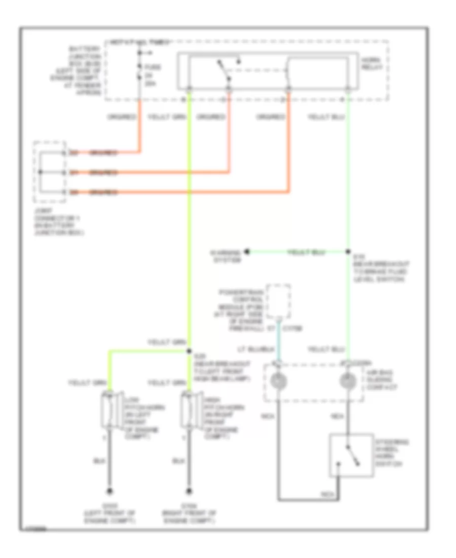
HORN Horn Wiring Diagram for Lincoln Aviator 2003 List of elements for Horn Wiring Diagram for Lincoln Aviator 2003: 19 20a Air bag sliding contact Battery junction box (bjb) (left side of engine compt, at fender apron) C175b C218a Fuse G104 (right front of engine compt) G105 (left front of engine compt) High pitch horn (in right front of engine compt) Horn relay Hot at all times Joint connector 1 (in battery junction box) Low pitch horn (in left front of engine compt) Nca Powertrain control module (pcm) (at right side of engine firewall) S15 (near breakout to brake fluid level switch) S25 (near breakout to left front high beam lamp) Steering wheel horn switch Warning system
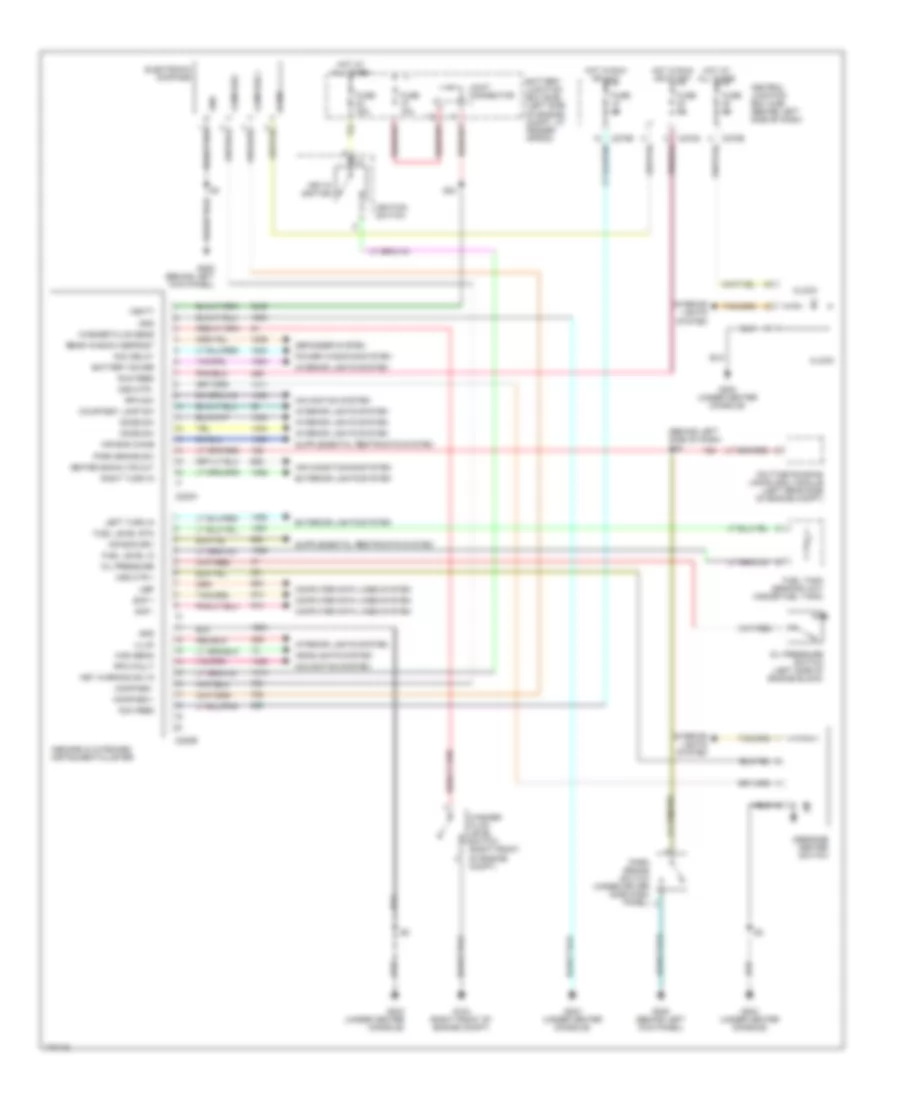
INSTRUMENT CLUSTER Instrument Cluster Wiring Diagram for Lincoln Aviator 2003 List of elements for Instrument Cluster Wiring Diagram for Lincoln Aviator 2003: 69 (behind left side of dash) s35 Acc delay Acc feed Air bag chime Air bag drv Air conditioning system Battery junction box (bjb) (left side of engine compt, at fender apron) Battery saver C220a C220b C270d C270e Central junction box (cjb) (behind left side of dash) Clock Compass + Compass - Computer data lines system Courtesy lamp sw Daytime running lamps (drl) module (left rear side of engine compt) Defogger system Dome sw Electronic compass Exterior lights system Fuel level in Fuel level rtn Fuel tank sending unit (inside fuel tank) Fuse 10a Fuse 30a Fuse 5a G104 (right front of engine compt) G203 (under center console) G205 (behind left kick panel) Gnd Headlights system Heated backlite out High beam Hot at all times Hot in run or acc Hot in run or start Ignition switch Illum Inboard & outboard instrument cluster Interior lights system Joint connector Key in ignition Key warning sw in Left turn in Message center switch Msg ctr + Msg ctr - Navigation system Oil pressure Oil pressure switch (left side of engine block) Park brake sw Park brake switch (under driver side dash panel) Power windows system Rear window defrost Right turn in Rpa fault Rpa sw Run feed S24 Scp + Scp - Ubp V ign Vbatt Washer fluid level switch (right front of engine compt) Washer fluid sens
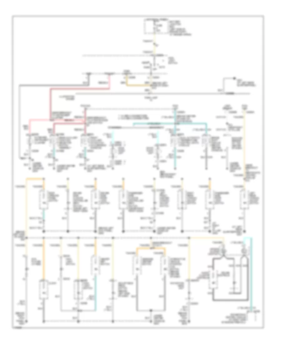
INTERIOR LIGHTS Courtesy Lamps Wiring Diagram for Lincoln Aviator 2003 List of elements for Courtesy Lamps Wiring Diagram for Lincoln Aviator 2003: 55 (behind center of dash on main bundle) s15 (behind left kick panel) g205 (near breakout to cargo lamp assembly) s6 (near breakout to dual automatic temperature control module) s24 (near breakout to left vanity mirror lamp) s2 (near right front passenger door grommet) s33 (under center console) g203 Auxiliary junction box (ajb) (right side of engine compt, at fender apron) Battery junction box (bjb) (left side of engine compt, at fender apron) Battery saver relay Breakout to liftgate disarm switch) s6 C205b C220a C228b C270a C270d C270e Cargo lamp assembly Cargo space lamp Central junction box (cjb) (behind left side of dash) Console) (late production) ohc jumper s1 Dome on off locked off Dual automatic temperature control (datc) module Front interior map lamps assembly Fuse 10a Fuse 15a Fuse 5a G202 (behind right kick panel) G203 (under center console) G205 (behind left kick panel) G401 (at left rear quarterpanel) G402 (at right ``d" pillar) Glove box lamp Homelink module (early production) (on front of roof) Homelink module (late production) (on front of roof) Hot at all times Hot in run or start Inboard instrument cluster Joint connector 1 (in battery junction box) Joint connector 4 (in rear auxiliary junction box) Left exterior rear view mirror Left front footwell lamp Left vanity mirror lamp Main light switch Microprocessor Off Ohc jumper s2 (late production) (in overhead console) On with door open manual on Puddle lamp relay Rear interior map lamps assembly Right exterior rear view mirror Right front footwell lamp Right vanity mirror lamp S27 S8 (near breakout to cargo lamp assembly) Instrument Illumination Wiring Diagram for Lincoln Aviator 2003 List of elements for Instrument Illumination Wiring Diagram for Lincoln Aviator 2003: 78 (at left rear quarterpanel) g401 (at right "d" pillar) g402 (behind left kick panel) g205 (behind left side of dash) s25 (behind right kick panel) g202 (near breakout to c211) s3 (near breakout to instrument cluster) s1 (near breakout to restraints control module) s12 (under center console) g203 (under center console) g207 Adjustable pedal switch (behind left side of dash) Air bag sliding contact Audio/ climate controls Auto Battery junction box (left side of engine compt, at fender apron) Brake shift module (below center console) C175b C205a C205b C205c C2065a C2065b C220b C2253c C228a C228b C240b c290a C290a C290a c240b C3193b C3198b C938a Cdx6 audio unit Cdx6 radio Clock Cruise controls Dm100 audio unit Dm100 radio Driver side climate controlled seat switch (inside left front door) Driver side door lock switch Dual automatic temperature control (datc) module Dvd player (w/ rse) Front auxiliary a/c switch (in overhead console) Fuse 20a G202 (behind right kick panel) G401 (at left rear quarterpanel) Gnd Head Hot at all times Illumination dimmer Interactive vehicle dynamics (ivd) switch (behind center of dash) Left front master window adjust switch Left rear window adjust switch Light sensor Main light switch Memory set switch Message center switch Navigation head unit Nca Of dash on main bundle) s2 Off Outboard instrument cluster Park Park lamp in Passenger side climate controlled seat switch (inside right front door) Passenger side door lock switch Powertrain control module (at right side of engine firewall) Pwm dim in Pwm high Pwm low Pwm out Rear auxiliary function selector switch assembly Right rear window adjust switch Roof opening panel switch S13 (near right "d" pillar) S27 Sunload sensor (at top center of dash) W/ gen 2 connectors w/o gen 2 connectors
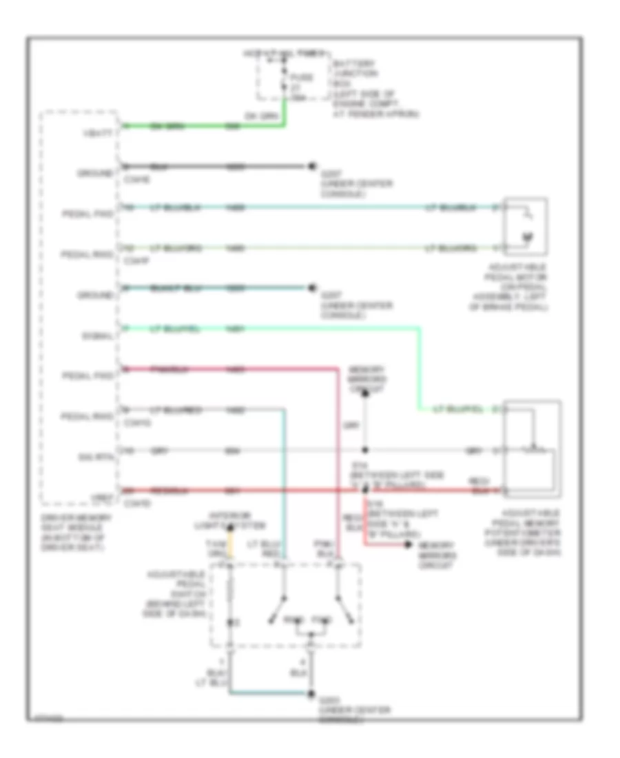
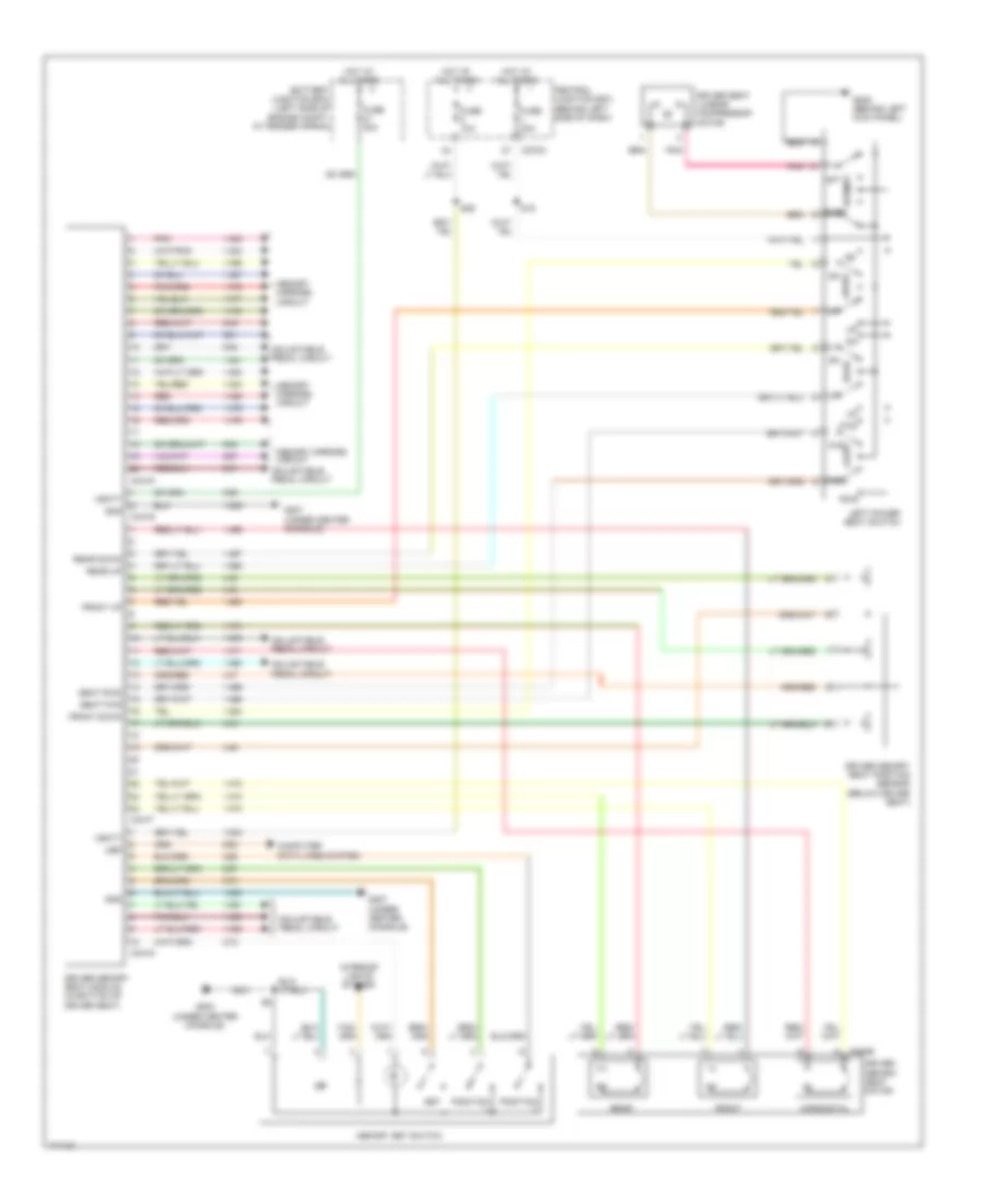
MEMORY SYSTEMS Adjustable Pedal Wiring Diagram for Lincoln Aviator 2003 List of elements for Adjustable Pedal Wiring Diagram for Lincoln Aviator 2003: 25 Adjustable pedal memory potentiometer (under driver's side of dash) Adjustable pedal motor (on pedal assembly, left of brake pedal) Adjustable pedal switch (behind left side of dash) Battery junction box (left side of engine compt, at fender apron) C341d C341e C341f C341g Driver memory seat module (in bottom of driver seat) Fuse 30a Fwd G203 (under center console) G207 (under center console) Ground Hot at all times Interior lights system Memory mirrors circuit Pedal fwd Pedal rwd Rwd S14 (between left side "a" & "b" pillars) Sig rtn Signal Vbatt Vref Driver"s Memory Seat Wiring Diagram for Lincoln Aviator 2003 List of elements for Driver"s Memory Seat Wiring Diagram for Lincoln Aviator 2003: 50 (under center console) Adjustable pedal circuit Aft Battery junction box (left side of engine compt, at fender apron) C270a C341d C341e C341f C341g C353b Central junction box (behind left side of dash) Computer data lines system Driver memory seat module (in bottom of driver seat) Driver memory seat motor Driver memory seat position sensor (below driver seat) Driver seat lumbar compressor motor Fore Front Front down Front up Fuse 10a Fuse 30a Fwd G203 G205 (behind left kick panel) G207 G207 (under center console) Gnd Horizontal Hot at all times Interior lights system Left power seat switch Lumbar Memory mirrors circuit Memory set switch Pnk Position Rear Rear down Rear up Red Rwd S19 S29 Seat Seat fwd Seat rwd Set Ubp Vbatt Memory Mirrors Wiring Diagram for Lincoln Aviator 2003 List of elements for Memory Mirrors Wiring Diagram for Lincoln Aviator 2003: 30 (between left side "a" and "b" pillars) s14 Adjustable pedal memory potentiometer (under driver's side of dash) C270a C341d Central junction box (behind left side of dash) Common Down Driver memory seat module (in bottom of driver seat) Exterior rear view mirror switch Fuse 5a G205 (behind left kick panel) Hot at all times Left Left exterior rear view mirror Left mirror select Left/ right Lh l/r Lh up/down Pnk Pwr Red Rh l/r Rh up/dn Right Right exterior rear view mirror Right mirror select S16 Sig rtn Up/ down Vref
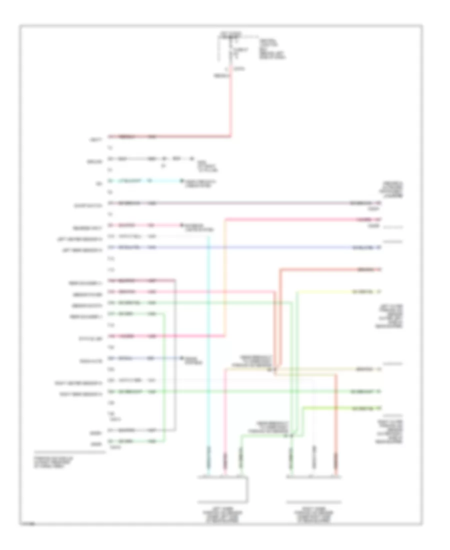
NAVIGATION Navigation Wiring Diagram for Lincoln Aviator 2003 List of elements for Navigation Wiring Diagram for Lincoln Aviator 2003: 41 (at right "d" pillar) g402 (behind left side kick panel, near grommet) s40 Accy delay relay Battery junction box (left side of engine compt, at fender apron) C2253a C2253c C270a C270c C270h C4209a C4209b Central junction box (behind left side of dash) Circuit breaker 30a Computer data lines system Delay accy Engine controls system Exterior lights system Fuse 3 20a Fuse 6 5a G205 (behind left kick panel) Gps antenna Ground Hot at all times Inside rear view mirror unit Mic+ Mic- Navigation electronic control unit module (bottom of rear cargo area) Navigation head unit Nca Pwr Red Rev Reverse S13 (behind left S50 Scp+ Scp- Side of dash) Sound systems Vbatt Vss in Parking Assistant Wiring Diagram for Lincoln Aviator 2003 List of elements for Parking Assistant Wiring Diagram for Lincoln Aviator 2003: 37 (near breakout to inner right parking aid sensor) s1 (near breakout to inner right parking aid sensor) s2 C220a C220b C270a C4014 C4015 Central junction box (behind left side of dash) Computer data lines system Exterior lights system Fuse 27 5a G402 (at right ``d" pillar) Ground Hot in run or start Inboard & outboard instrument cluster Iso Left center sensor in Left inner parking aid sensor (inner left side of rear bumper) Left outer parking aid sensor (outer left side of rear bumper) Left rear sensor in On/off switch Parking aid module (in right rear end of cargo area) Radio mute Rear sounder (+) Rear sounder (-) Reverse input Right center sensor in Right inner parking aid sensor (inner right side of rear bumper) Right outer parking aid sensor (outer right side of rear bumper) Right rear sensor in Sensor power Sensor sig rtn Sndr+ Sndr- Sound systems Status led Vbatt
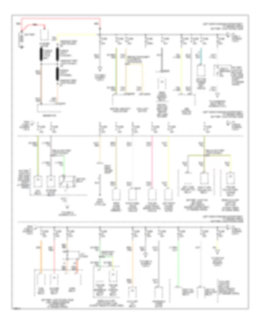
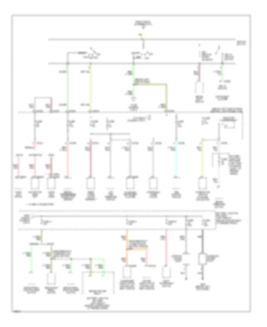
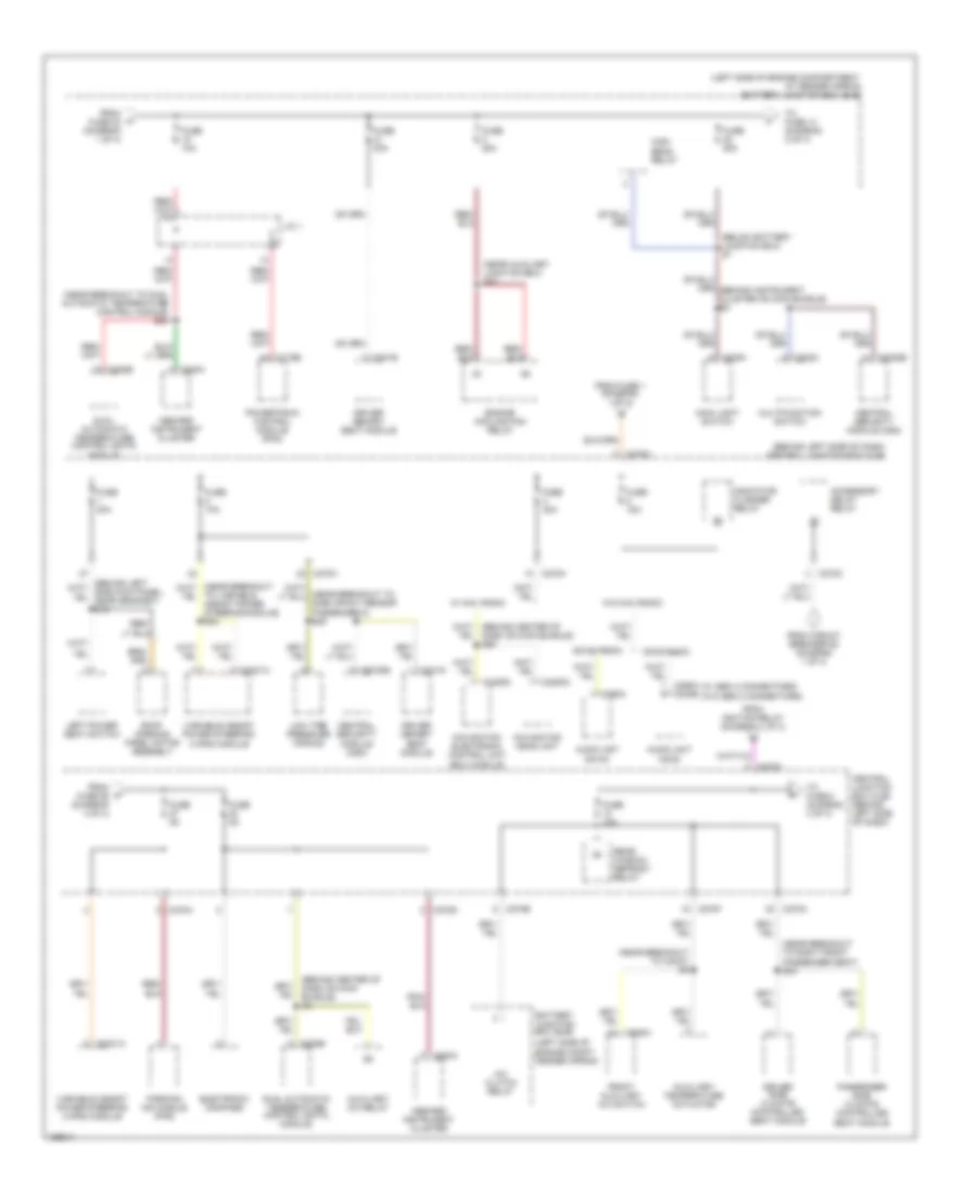
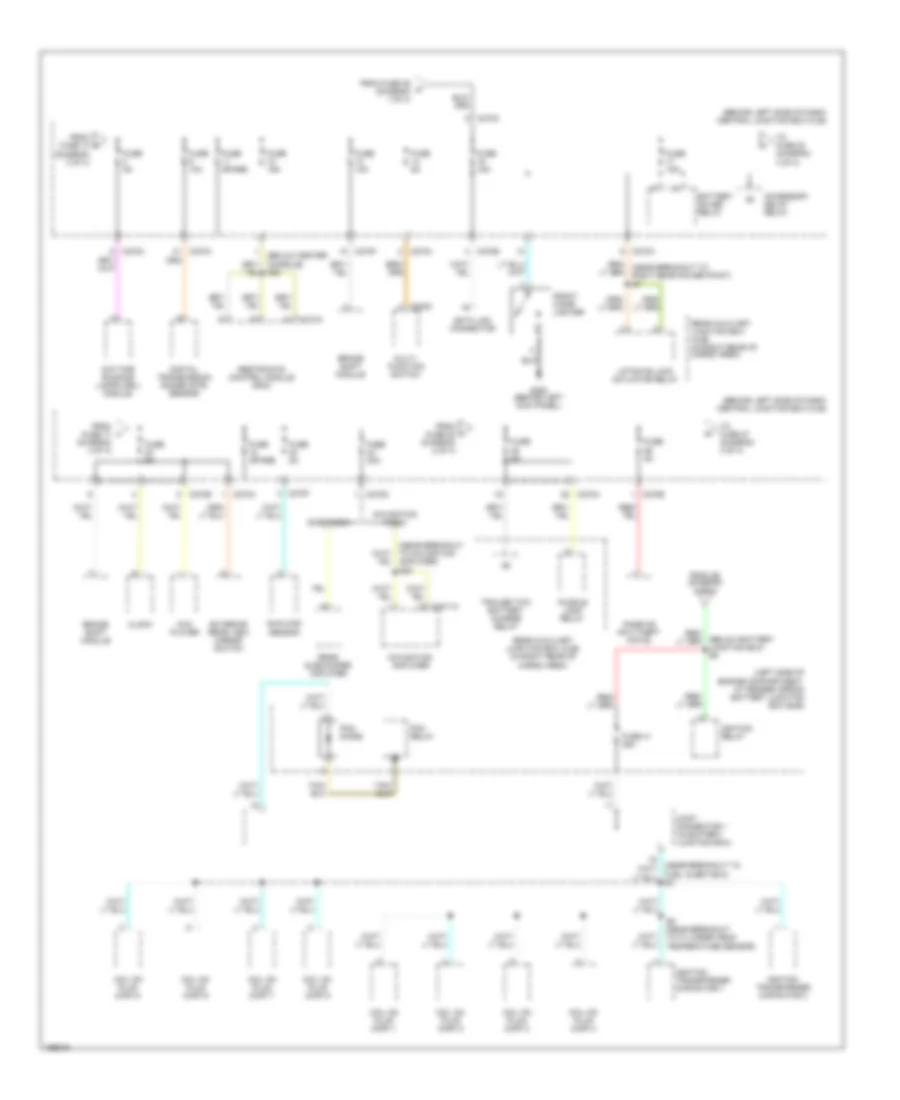
POWER DISTRIBUTION Power Distribution Wiring Diagram (1 of 4) for Lincoln Aviator 2003 List of elements for Power Distribution Wiring Diagram (1 of 4) for Lincoln Aviator 2003: 71 (behind instrument cluster on main bundle) s7 (below battery junction box) s14 (below battery junction box) s44 (in right rear of cargo area) (left side of engine compartment, at fender apron) battery junction box (bjb) (near battery junction box) s1 (near battery junction box) s2 (near battery junction box) s3 (near right ``d" pillar) s32 (right ``d" pillar) Abs control module Auxiliary a/c relay Auxiliary junction box (ajb) (right side of engine compt, at fender apron) Battery Battery junction box (bjb) (left side of engine compartment, at fender apron) Battery junction box (bjb) (left side of engine compt, at fender apron) Blower motor relay C102a C205a C270c C281b C3008e Central junction box (cjb) (behind left side of dash) Central security module (csm) Charge relay Circuit breaker 30a Daytime running lamps (drl) module Four wheel drive control module From fuse 19 (diagram 1 of 4) From fuse 6 (diagram 1 of 4) Fuel pump relay Fuse 20a Fuse 30a Fuse 40a Fuse 50a Fuse 60a Fuse open G402 Generator Horn relay Ignition relay J/c 1 (in bjb) Left front power window motor Left hid headlamp relay Left turn trailer tow relay Main light switch Pcm relay Rear auxiliary junction box (ajb) Rear auxiliary junction box (ajb) (in right rear of cargo area) Rear window defrost relay Rear wiper motor assembly Red Right hid headlamp relay Right rear power point Right turn Starter motor Starter motor relay To accessory delay relay (diagram 3 of 4) To fuse 10 (diagram 3 of 4) To fuse 11 (diagram 1 of 4) To fuse 15 (diagram 3 of 4) To fuse 16 (diagram 4 of 4) To fuse 26 (diagram 1 of 4) To fuse 5 (diagram 3 of 4) To ignition switch (diagram 2 of 4) Trailer electronic brake control module Trailer tow battery Trailer tow parking lamp relay Trailer tow relay Trailer tow reversing lamps relay Windshield wiper motor Power Distribution Wiring Diagram (2 of 4) for Lincoln Aviator 2003 List of elements for Power Distribution Wiring Diagram (2 of 4) for Lincoln Aviator 2003: 71 (behind left side of dash) central junction box (cjb) (behind left side of dash) s8 (left side (near breakout to brake fluid level switch) s3 (near breakout to restraints control module) s35 Abs control module Acc Audio unit (cdx6) Audio unit (dm100) Battery junction box (bjb) Battery junction box (bjb) (left side of engine compartment, at fender apron) Brake pedal position (bpp) switch Brake pressure switch Brake shift module C220b C2253c C240b C270a C270b C270d C270e C270f C270g C270h C290a C3031b C3036b Cdx6 Console Console 2 power point Digital digital transmission transmission range (dtr) sensor Dm100 Driver side climate controlled seat module Dynamics (ivd) switch From fuse 22 (diagram 3 of 4) From fuse 23 (diagram 1 of 4) Fuse 10a Fuse 14 15a Fuse 20a Fuse 2a Fuse 31 30a Fuse 32 30a Fuse 5a G205 (behind left kick panel) Ignition switch Indicator flasher relay Instrument cluster Interactive vehicle Key in ignition Key in ignition switch Key removal inhibit solenoid Low tire pressure module Navigation Navigation head unit Of engine compt, at fender apron) Off Outboard instrument cluster Passenger side climate controlled seat module Power point Rear wiper motor assembly Red Redundant pedal switch Right power seat switch Run Start To fuse 25 (diagram 4 of 4) To s5 (diagram 4 of 4) W/ gen 2 connectors W/ ivd W/o ivd Windshield wiper motor Power Distribution Wiring Diagram (3 of 4) for Lincoln Aviator 2003 List of elements for Power Distribution Wiring Diagram (3 of 4) for Lincoln Aviator 2003: 79 (behind center of dash on main bundle) s4 (behind left side of dash) central junction box (cjb) (below battery junction box) s1 (left side of (left side of engine compartment, at fender apron) battery junction box (bjb) (near auxiliary junction box) s27 (near breakout to c3047) s9 (near breakout to dual automatic temperature control module) s24 (near breakout to right front passenger seat) s34 (near breakout to side impact sensor passenger 2) s29 (w/ gen 2 connectors) (w/o gen 2 connectors) A/c clutch relay Accessory delay relay Audio unit cdx6 Audio unit dm100 Auxiliary a/c relay Auxiliary temperature actuator Battery junction box (bjb) C175b C202c C205a C220a C2231a C2253c C228b C270a C270b C270c C270d C270f C270h C290a C3008e C341e C341g C4209a C938a Cdx6 radio Central junction box (cjb) (behind left side of dash) Central security module (csm) Dm100 radio Driver memory seat module Driver side climate controlled seat module Dual automatic temperature control (datc) module Electronic compass Engine compt, fender apron) Engine cooling fan relay From circuit breaker 62 (diagram 1 of 4) From fuse 1 (diagram 1 of 4) From fuse 23 (diagram 1 of 4) From fuse 26 (diagram 4 of 4) From ignition relay (diagram 1 of 4) Front auxiliary a/c switch Fuse 10a Fuse 15a Fuse 20a Fuse 30a Fuse 5a High beam relay Inboard instrument cluster Indicator flasher relay J/c 1 Left power seat switch Low tire pressure module Main light switch Multifunction switch Navigation electronic control unit (ecu) module Navigation head unit Parking aid module (pam) Passenger side climate controlled seat module Powertrain control module (pcm) Rear window defrost relay Roof opening panel motor assembly To fuse 14 (diagram 2 of 4) To fuse 8 (diagram 4 of 4) To variable assist power steering module) s24 Variable assist power steering (vaps) module W/ nav radio W/o nav radio Power Distribution Wiring Diagram (4 of 4) for Lincoln Aviator 2003 List of elements for Power Distribution Wiring Diagram (4 of 4) for Lincoln Aviator 2003: 65 (behind left side of dash) central junction box (cjb) (below battery junction box) s5 (left side of engine compartment, at fender apron) battery junction box (bjb) Accessory delay relay Amplifier) s20 Battery saver relay Brake shift module C202c C270a C270c C270e C270f C270g C270h C310a C4211a Cdx6 radio Clock Coil on plug (cop) 1 Coil on plug (cop) 2 Coil on plug (cop) 3 Coil on plug (cop) 4 Coil on plug (cop) 5 Coil on plug (cop) 6 Coil on plug (cop) 7 Coil on plug (cop) 8 Data link connector Daytime running lamps (drl) module Digital transmission range (dtr) sensor Dvd player Exterior rear view mirror switch From fuse 10 (diagram 3 of 4) From fuse 17 (diagram 4 of 4) From fuse 22 (diagram 2 of 4) From fuse 29 (diagram 1 of 4) From s8 (diagram 2 of 4) Front cigar lighter Fuse 10a Fuse 15a Fuse 20a Fuse 41 25a Fuse 5a Fuse spare G205 (behind left kich panel) Ignition relay Ignition transformer capacitor 1 Ignition transformer capacitor 2 Joint connector 1 (in battery junction box) Liftgate lock actuator relay Multi- function switch Navigation amplifier Navigation radio Passive anti-theft (pats) Pcm diode Pcm relay Puddle lamp relay Rear auxiliary junction box (ajb) (in right rear of cargo area) Rear subwoofer amplifier Restraints control module (rcm) S36 S5 (near breakout to cylinder head temperature sensor) Sunload sensor To fuse 20 (diagram 4 of 4) To fuse 27 (diagram 3 of 4) Trailer tow battery charge relay
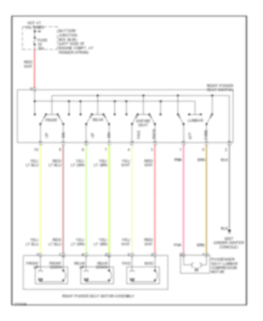
POWER SEATS Heated Seats Wiring Diagram (1 of 2) for Lincoln Aviator 2003 List of elements for Heated Seats Wiring Diagram (1 of 2) for Lincoln Aviator 2003: 46 (inside left front door) driver side climate controlled seat switch 0) cool 1) off 2) heat 3) off 4) low 5) medium low 6) medium 7) medium high 8) high Back sens Back temp + Back temp - Battery junction box (bjb) (left side of of engine compt, at fender apron) Blower tach C270a C3031a C3031b Central junction box (cjb) (behind left side of dash) Comparitor Computer data lines system Cool Cool led Cush sens Cush temp+ Cush temp- Driver side climate controlled seat backrest element Driver side climate controlled seat cushion element Driver side climate controlled seat fan (below driver seat) Driver side climate controlled seat module (in bottom of driver seat) Electronics Fan + Fan - Fuse 10a Fuse 30a G205 (behind left kick panel) G207 (under center console) Ground Heat Heat led Hot Hot at all times Hot in run or start Ign Illumination Interior lights system Red S34 S35 Sens rtn Temp + Temp - Ubp Vbatt Heated Seats Wiring Diagram (2 of 2) for Lincoln Aviator 2003 List of elements for Heated Seats Wiring Diagram (2 of 2) for Lincoln Aviator 2003: 39 0) cool 1) off 2) heat 3) off 4) low 5) medium low 6) medium 7) medium high 8) high Back sens Back temp + Back temp - Blower tach C3036a C3036b Comparitor Computer Cool Cool led Cush sens Cush temp+ Cush temp- Data lines Electronics Fan + Fan - G207 (under center console) G207 (under centre console) Ground Heat Heat led Hot Ign Illumination Interior lights system Passenger side climate controlled seat backrest element Passenger side climate controlled seat cushion element Passenger side climate controlled seat fan (below front passenger seat) Passenger side climate controlled seat module (in bottom of passenger seat) Passenger side climate controlled seat switch (inside right front door) Red Sens rtn System Temp + Temp - Ubp Vbatt Passenger"s Power Seat Wiring Diagram for Lincoln Aviator 2003 List of elements for Passenger"s Power Seat Wiring Diagram for Lincoln Aviator 2003: 22 Aft Back Battery junction box (bjb) (left side of engine compt, at fender apron) Bwd Entire seat Fore Front Front down Front up Fuse 30a Fwd G207 (under center console) Hot at all times Lumbar Passenger seat lumbar compressor motor Pnk Pnk pnk Rear Rear down Rear up Right power seat motor assembly Right power seat switch
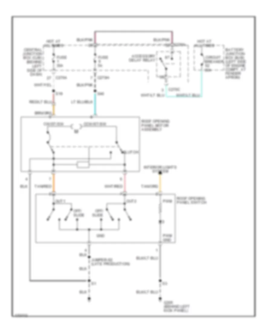
POWER TOP/SUNROOF Power Top/Sunroof Wiring Diagram for Lincoln Aviator 2003 List of elements for Power Top/Sunroof Wiring Diagram for Lincoln Aviator 2003: 27 Accessory delay relay Battery junction box (bjb) (left side of engine compt, at fender apron) C270a C270c C270h Ccw/st/sw Central junction box (cjb) (behind left side of dash) Circuit breaker 30a Clutch Cw/st/sw Fuse 30a Fuse 5a G205 (behind left kick panel) Gnd Hot at all times Interior lights system Jumper-s2 (late production) Off/ slide Out1 Out2 Pwm Pwm gnd Roof opening panel motor assembly Roof opening panel switch S19 S40 Tan/red
POWER WINDOWS Power Windows Wiring Diagram for Lincoln Aviator 2003 List of elements for Power Windows Wiring Diagram for Lincoln Aviator 2003: 43 (at left rear quarterpanel) g401 (behind left kick panel) g205 (near breakout to c311) s6 (not used) (under center console) g207 Accessory delay relay Battery junction box (bjb) (left side of engine compt, at fender apron) C220a C270a C270c C270e C270h C3008e C3008f C3193a C3193b Central junction box (cjb) (behind left side of dash) Central security module (csm) (behind right rear seat) Circuit breaker 62 30a Fuse 17 15a Fuse 19 30a Fuse 2 30a Fuse 29 60a Fuse 6 5a Fuse 6 60a G207 (under center console) G401 (at left rear quarterpanel) G402 (at right ``d" pillar) Hot at all times Inboard instrument cluster Interior lights system Left front power window motor Left rear power window motor Left rear window adjust switch Liftgate glass actuator Lock out Master left & right front window adjust switch One-touch Right front power window motor Right rear power window motor Right rear window adjust switch S40 Vbatt
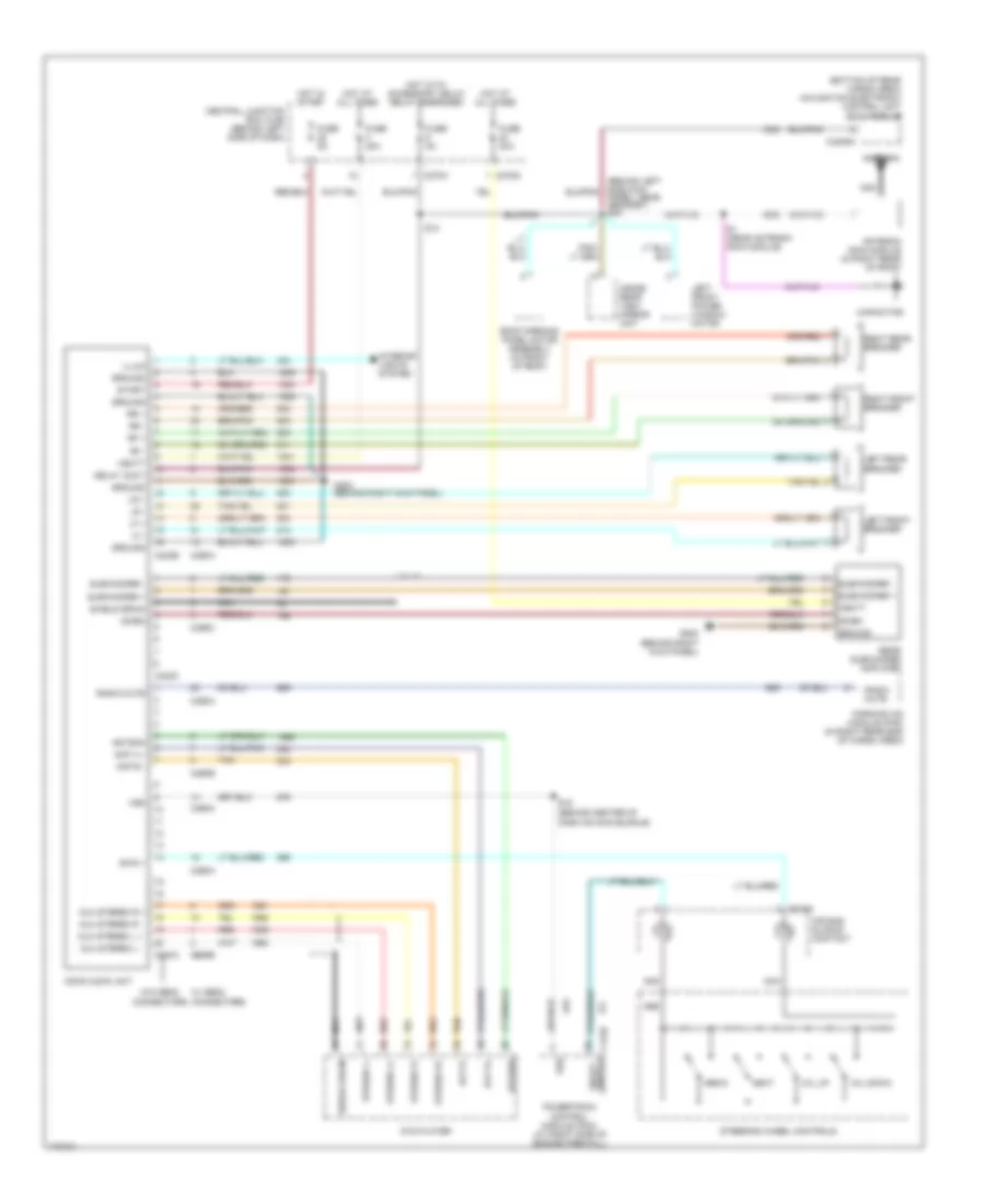
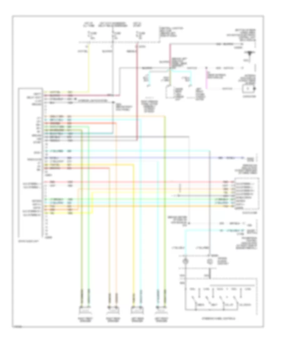
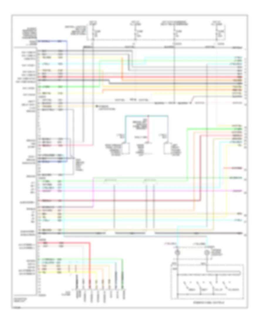
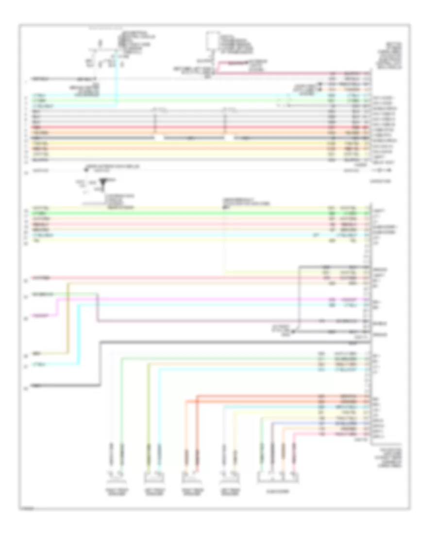
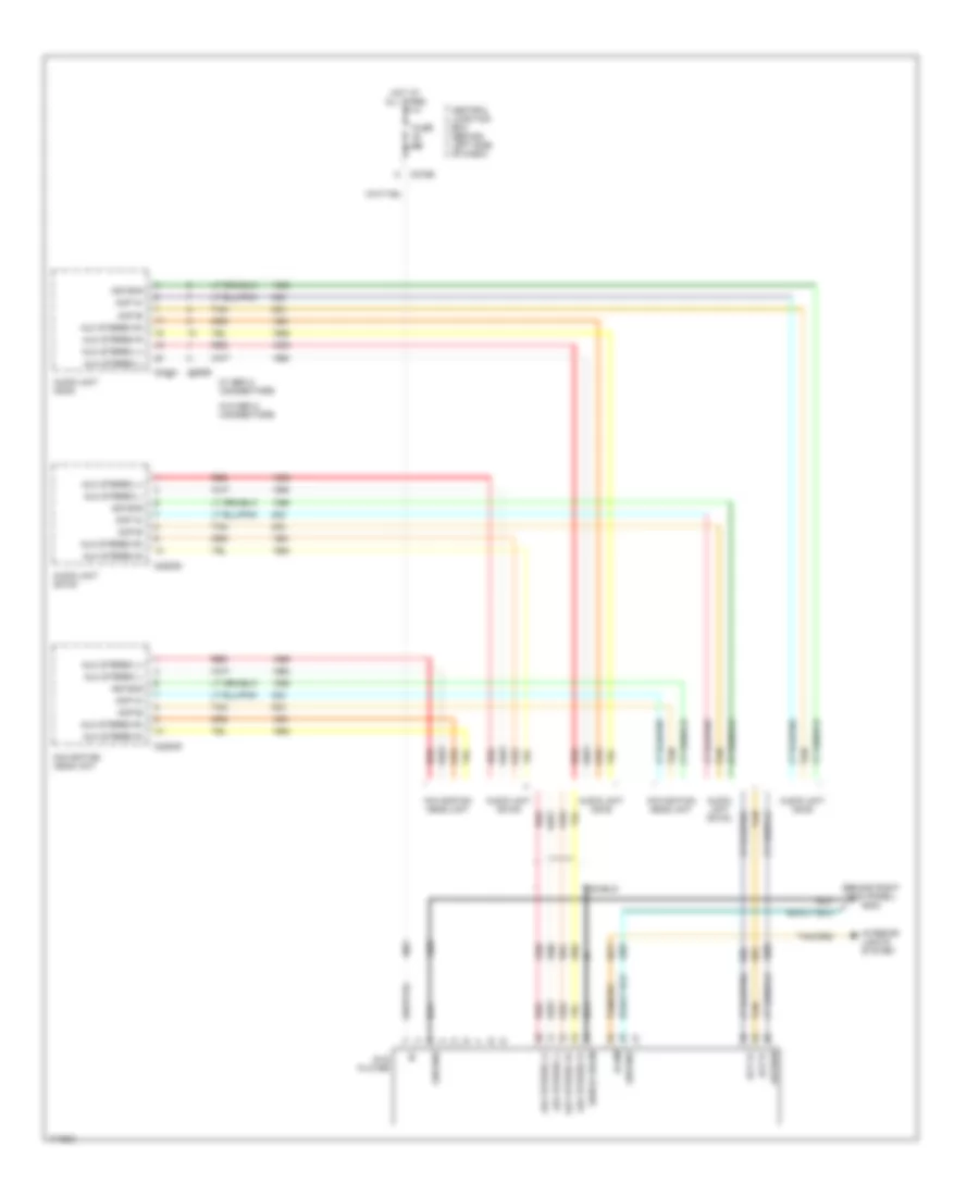
RADIO Base Radio Wiring Diagram for Lincoln Aviator 2003 List of elements for Base Radio Wiring Diagram for Lincoln Aviator 2003: 88 (at right side of engine firewall) (behind center of dash on main bundle) (bottom of rear cargo area) navigation electronic control unit (ecu) module Acp a + Acp a+ Acp b - Acp b- Air bag sliding contact Antenna Antenna gain module (in right rear of roof) Asyson Aux stereo l + Aux stereo l - Aux stereo r + Aux stereo r - C175b C218a C240a C240b C240c C270g C270h C290a C290b C290c C4209a Capacitor Cd/en Cdx6 audio unit Central junction box (cjb) (behind left side of dash) Delay accy Dvd player Fuse 20a Fuse 5a G202 (behind right kick panel) Gnd Ground Hot at all times Hot in start Hot with accessory delay relay energized Illum Inside rear view mirror unit Interior lights system Left front power window motor Left front speaker Left rear speaker Lf + Lf - Lr + Lr - Media Nca Next On-off switch Panel, near grommet) s40 Parking aid module (pam) (in right rear end of cargo area) Powertrain control module (pcm) Radio mute Rear subwoofer amplifier Red Rf + Rf - Right front speaker Right rear speaker Roof opening panel motor assembly (in front of roof) Rr + Rr - S1 (near antenna gain module) S13 S18 Sheild drain Shield drain Start Steering wheel controls Stereo l+ Stereo l- Stereo r+ Stereo r- Subwoofer + Subwoofer - Sws + Tan Vbatt Vol down Vol up Vss W/ gen2 connectors W/o gen2 connectors Premium Sound Radio Wiring Diagram, DM100 for Lincoln Aviator 2003 List of elements for Premium Sound Radio Wiring Diagram, DM100 for Lincoln Aviator 2003: 68 (behind center of dash on main bundle) s18 (bottom of rear cargo area) navigation electronic control unit (ecu) module Acp a + Acp b - Air bag sliding contact Antenna Antenna gain module (in right rear of roof) Asyson Aux stereo l + Aux stereo l - Aux stereo r + Aux stereo r - C175b C218a C270h C290a C290b C4209a Capacitor Central junction box (cjb) (behind left side of dash) Delay accy Dm100 audio unit Dvd player Fuse 20a Fuse 5a G202 (behind right kick panel) Gnd Ground Hot at all times Hot in start Hot with accessory delay relay energized Illum Inside rear view mirror unit Interior lights system Left front power window motor Left front speaker Left rear speaker Lf + Lf - Lr + Lr - Media Nca Next On-off switch Panel, near grommet) s40 Parking aid module (pam) (in right rear end of cargo area) Powertrain control module (pcm) (at right side of engine firewall) Radio mute Red Rf + Rf - Right front speaker Right rear speaker Roof opening panel motor assembly (in front of roof) Rr + Rr - S1 (near antenna gain module) S13 Shield drain Start Steering wheel controls Sws + Tan Vbatt Vol down Vol up Vss Premium Sound Radio Wiring Diagram, with Navigation (1 of 2) for Lincoln Aviator 2003 List of elements for Premium Sound Radio Wiring Diagram, with Navigation (1 of 2) for Lincoln Aviator 2003: 79 (behind left side kick panel, near grommet) (in right rear end of cargo area) parking aid module (pam) Acp a+ Acp b+ Acp b- Air bag sliding contact Asyson Aux stereo l+ Aux stereo l- Aux stereo r+ Aux stereo r- C218a C2253a C2253b C2253c C2253d C270g C270h Central junction box (cjb) (behind left side of dash) Delay accy Drain Dvd player Enable Fuse 20a Fuse 5a G202 (behind right kick panel) Gnd Ground Hot at all times Hot in start Hot with accessory delay relay energized Illum Inside rear view mirror unit Interior lights system Left front power window motor Lf + Lf - Lr + Lr - Media Nav can a+ Nav can b- Nav video b Nav video g Nav video r Nav video shield Nav video sync Nav voice + Nav voice - Navigation head unit Nca Next Radio mute Red Rf + Rf - Roof opening panel motor assembly (in front of roof) Rr + Rr - S13 S40 S50 Sheild Shield drain Start Steering wheel controls Stereo l+ Stereo l- Stereo r+ Stereo r- Subwoofer + Subwoofer - Sws + Tan Vbatt Video rtn Vol down Vol up Vss Premium Sound Radio Wiring Diagram, with Navigation (2 of 2) for Lincoln Aviator 2003 List of elements for Premium Sound Radio Wiring Diagram, with Navigation (2 of 2) for Lincoln Aviator 2003: 55 (at right "d" pillar) g402 (between left side "b" & "c" pillars) s20 (bottom of rear cargo area) navigation electronic control unit (ecu) module (near antenna gain module) (near breakout to navigation amplifier) s20 Antenna Antenna gain module (in right rear of roof) C175b C4209a C4211a C4211b Capacitor Computer data lines system Delay accy Digital transmission ranger sensor (lower left side of transmission) Enable Exterior lights system Ground Left front speaker Left rear speaker Lf + Lf - Lr + Lr - Nav can a+ Nav can b- Nav video b Nav video g Nav video r Nav voice + Nav voice - Navigation amplifier (in right rear corner of cargo area) Nca On-off switch Powertrain control module (pcm) (at right side of engine firewall) Red Rf + Rf - Right front speaker Right rear speaker Rr + Rr - S18 (behind center of dash on main bundle) Shield drain Spk 1+ Spk 1- Spk 2+ Spk 2- Subwoofer Subwoofer + Subwoofer - Vbatt Video rtn Video sync Vss Rear Seat Entertainment Wiring Diagram for Lincoln Aviator 2003 List of elements for Rear Seat Entertainment Wiring Diagram for Lincoln Aviator 2003: 29 (behind right kick panel) g202 Acp a+ Acp b- Asyson Audio unit cdx6 Audio unit dm100 Aux stereo l+ Aux stereo l- Aux stereo r+ Aux stereo r- C2253d C240a C270e C290b Central junction box (behind left side of dash) Dvd player Fuse 5a Ground Hot at all times Illum Interior lights system Navigation head unit Nca Red Shield Shield drain Tan W/ gen 2 connectors W/o gen 2 connectors
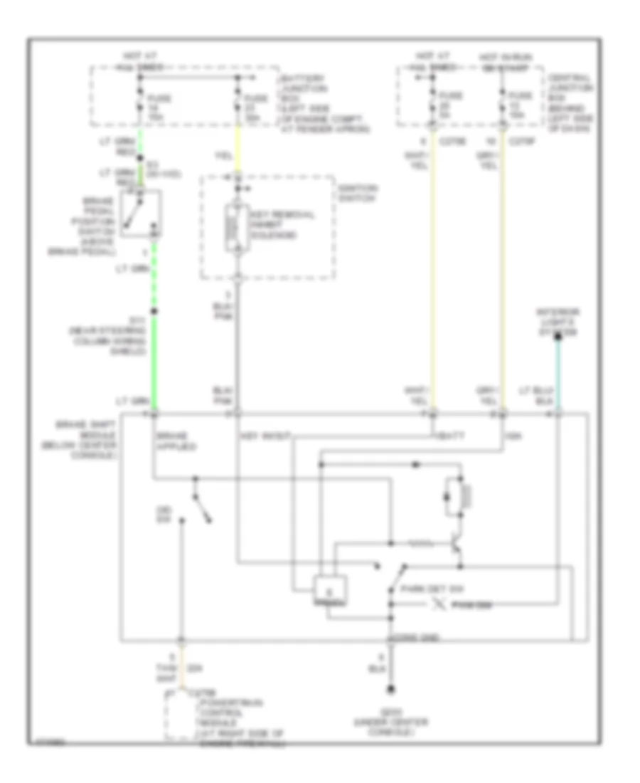
SHIFT INTERLOCK Shift Interlock Wiring Diagram for Lincoln Aviator 2003 List of elements for Shift Interlock Wiring Diagram for Lincoln Aviator 2003: 31 All times Battery junction box (left side of engine compt, at fender apron) Brake pedal position switch (above brake pedal) Brake shift module (below center console) C175b C270e C270f Central junction box (behind left side of dash) Cons gnd E prndl Fuse 10a Fuse 15a Fuse 30a Fuse 5a G203 (under center console) Hot at Hot in run Ign Ignition switch Interior lights system Key in/out Key removal inhibit solenoid O/d sw Or start Park det sw Powertrain control module (at right side of engine firewall) Pwm dim Red S11 (near steering column wiring shield) Tan/ Vbatt
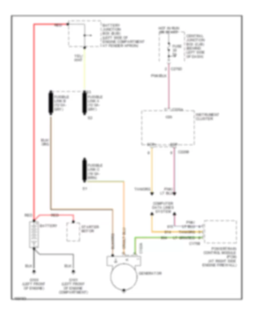
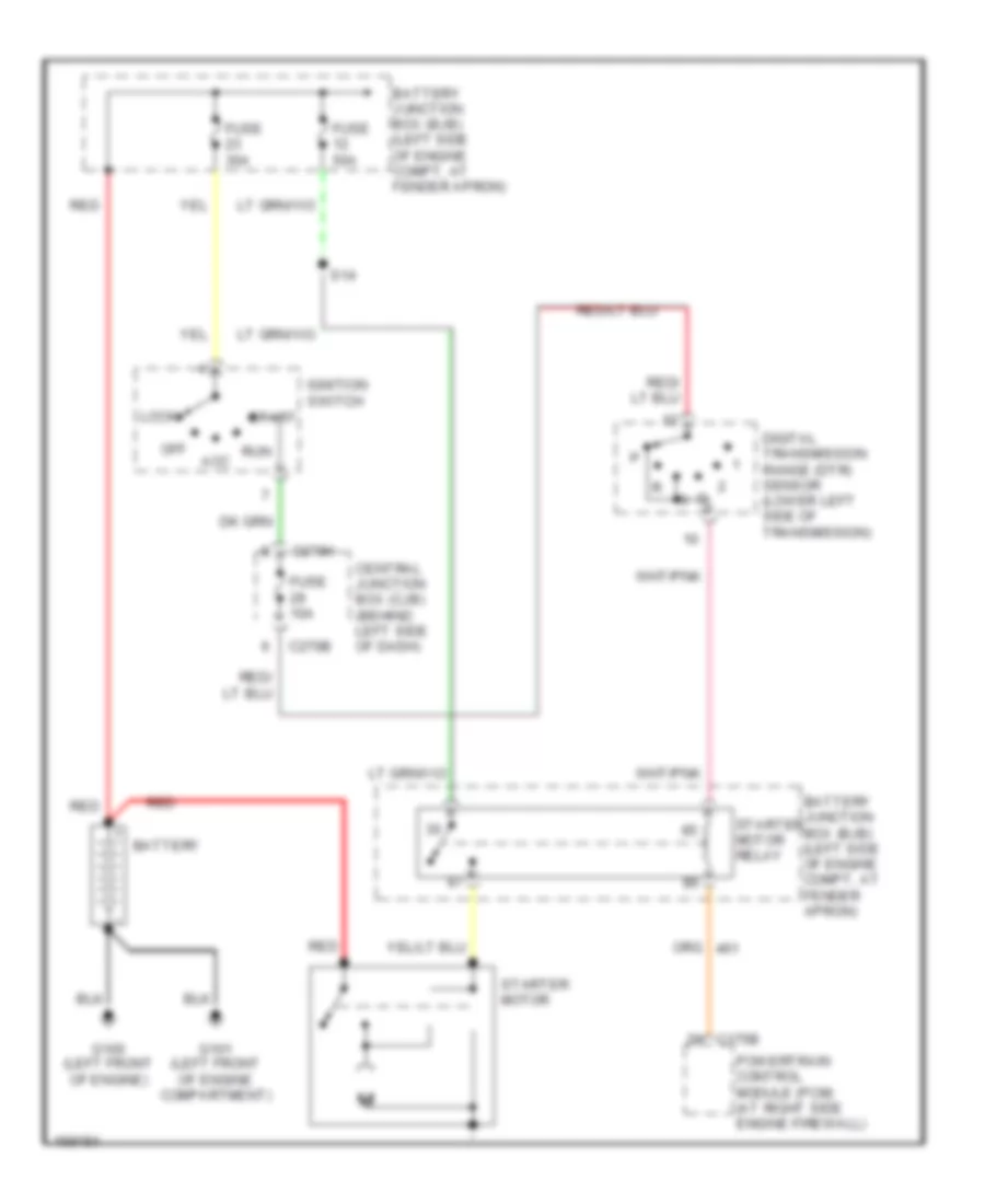
STARTING/CHARGING Charging Wiring Diagram for Lincoln Aviator 2003 List of elements for Charging Wiring Diagram for Lincoln Aviator 2003: 21 Battery Battery junction box (bjb) (left side of engine compartment at fender apron) C102a C175b C220a C220b C270d Central junction box (cjb) (behind left side of dash) Computer data lines system Fuse 5a G100 (left front of engine) G101 (left front of engine compartment) Generator Hot in run or start Ign Instrument cluster Powertrain control module (pcm) (at right side engine firewall) Red Scp+ Scp- Starter motor Starting Wiring Diagram for Lincoln Aviator 2003 List of elements for Starting Wiring Diagram for Lincoln Aviator 2003: 23 Acc Battery Battery junction box (bjb) (left side of engine compt, at fender apron) C175b C270b C270h Central junction box (cjb) (behind left side of dash) Digital transmission range (dtr) sensor (lower left side of transmission) Fuse 10a Fuse 30a Fuse 50a G100 (left front of engine) G101 (left front of engine compartment) Ignition switch Lock Off Powertrain control module (pcm) (at right side engine firewall) Red Run S14 Start Starter motor Starter motor relay
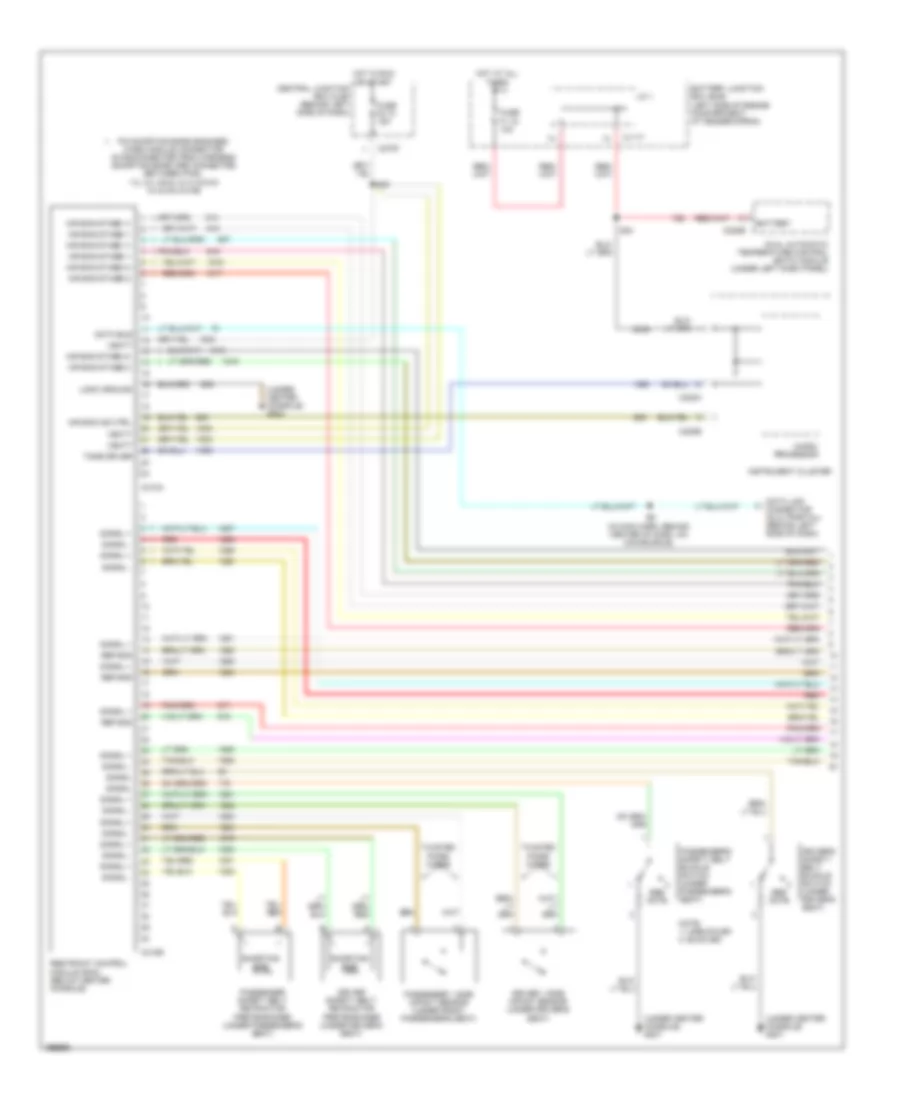
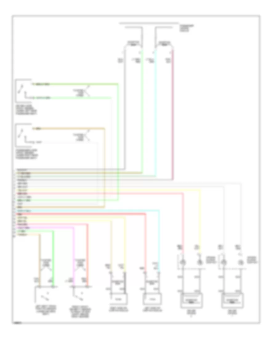
SUPPLEMENTAL RESTRAINTS Supplemental Restraints Wiring Diagram (1 of 2) for Lincoln Aviator 2003 List of elements for Supplemental Restraints Wiring Diagram (1 of 2) for Lincoln Aviator 2003: 50 (under center console) g203 (under center console) g207 Air bag ind ctrl Air bag stage 1+ Air bag stage 1- Air bag stage 2+ Air bag stage 2- Battery Battery junction box (bjb) (left side of engine compartment, at fender apron) C1117 C220a C220b C228b C270f C310a C310b Central junction box (cjb) (behind left side of dash) Data bus Data link connector (dlc) (partial) (behind left side of dash) Driver 1 side impact sensor (under driver's seat) Driver safety belt retractor pretensioner (under driver's seat) Driver's safety belt buckle switch (under driver's seat) Dual automatic temperature control (eatc) module (under left dash panel) Fuse f1.15 10a Fuse f2.12 15a Hot at all times Hot in run or start Instrument cluster J/c 1 Logic ground Micro- processor Note: 1: unbuckled 2: buckled Passenger 1 side impact sensor (under front passenger's seat) Passenger safety belt retractor pretensioner (under passenger's seat) Passenger's safety belt buckle switch (under passenger's seat) Pin shorting bars engaged when module connector is disconnected from harness (shorting bars are connected between pins: 1-2, 3-4, 5-6 & 13-14 c310a 3-4 & 5-6 c310b Red Ref/gnd Restraint control module (rcm) (below center console) S24 S36 S9 (in main harn, behind center of dash, on main bundle) See note Shorting bar Signal Signal + Signal - Tone driver Twisted pairs wires Vbatt Supplemental Restraints Wiring Diagram (2 of 2) for Lincoln Aviator 2003 List of elements for Supplemental Restraints Wiring Diagram (2 of 2) for Lincoln Aviator 2003: 13 Air bag sliding contact Driver 2 side impact sensor (under left rear passenger seat) Driver air bag Front impact severity sensor (in front of eng compt, behind front bumper) Left seat track position sensor (under driver's seat) Left side air curtain module Nca Passenger 2 side impact sensor (under right rear passenger seat) Passenger air bag module Red Right side air curtain module Shorting bar Twisted pair wires
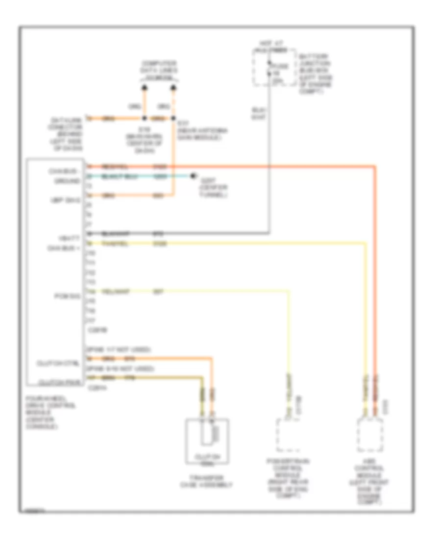
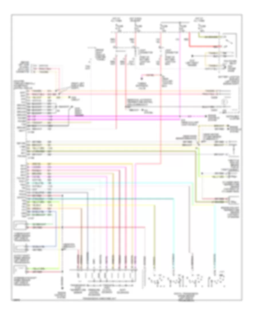
TRANSMISSION 4WD Wiring Diagram for Lincoln Aviator 2003 List of elements for 4WD Wiring Diagram for Lincoln Aviator 2003: 28 (center tunnel) (pins 1-7 not used) (pins 9-16 not used) Abs control module (left front side of engine compt) Battery junction (bjb) box (left side of engine compt) C155 C175b C281a C281b Can bus + Can bus - Clutch coil Clutch ctrl Clutch pwr Computer data lines system Datalink conector (behind left side of dash) Four-wheel drive control module (center console) Fuse 20a G207 Ground Hot at all times Pcm sig Powertrain control module (right rear side of eng compt) S19 (main harn, center of dash) S31 (near antenna gain module) Transfer case assembly Ubp diag Vbatt A/T Wiring Diagram for Lincoln Aviator 2003 List of elements for A/T Wiring Diagram for Lincoln Aviator 2003: 76 (behind left side of dash) data link connector (front left side of eng compt) (mounted through firewall) powertrain control module (near dual automatic temperature control module breakout) s24 (near heated oxygen sensor 21 breakout) s4 (near knock sensor breakout) (near pcm breakout) s2 4wd 4wd circuit A/c system Battery junction (bjb) box (left side of engine compt) Brake shift module (center tunnel) C175b C175e C175t C220a C220b Cht Cylinder head temperature sensor (top front of cylinder head) Digital transmission range sensor (left side of transmission) Dlc Ect Engine controls system Engine coolant temperature sensor (top right of engine) Fuse 15a Fuse 40a G107 (left front fender) G108 (right front fender) Ground Hot at all times Hot in run or start Instrument cluster Intermediate shaft speed sensor (left side of transmission) Iss Joint connector (part of battery junction box) O/d off Oss Output shaft speed sensor (left rear of transmission) Pcm power diode Pcm power relay Pcs a Pcs b Pcs c Power Pressure control solenoids Red Return S19 (near auxiliary junction box) S28 S29 S4 (near auxiliary junction box) Scp+ Scp- Shift solenoids Sig rtn Ss a Ss b Ss c Ss d Tcc sol Tcs Tft Thermo expansion valve Throttle postion sensor (top of throttle body) Torque conv clutch solenoid Tps sig Tr1 Tr2 Tr3a Tr4 Transmission fluid temperature sensor Transmission hardware unit Tss Turbine shaft speed sensor (left side of transmission) V ref Vbatt
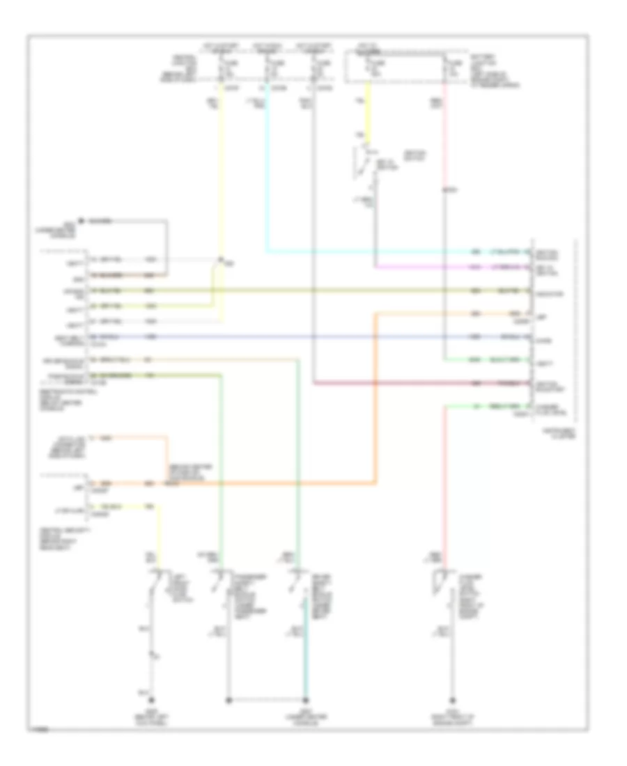
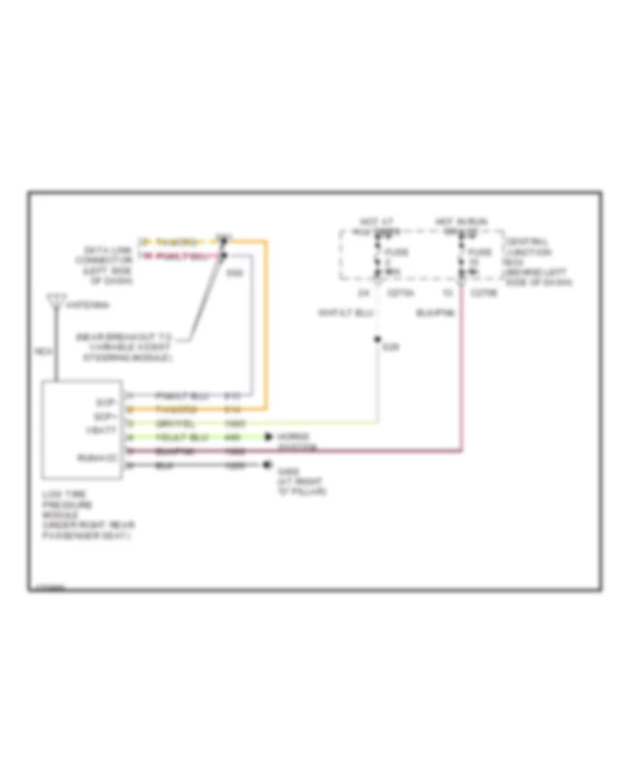
WARNING SYSTEMS Key Reminder & Seat Belt Warning Wiring Diagram for Lincoln Aviator 2003 List of elements for Key Reminder & Seat Belt Warning Wiring Diagram for Lincoln Aviator 2003: 48 (behind center of dash on main bundle) s19 Air bag ind Battery junction box (left side of engine compt, at fender apron) C220a C220b C270d C270e C270f C3008d C3008f C310a C310b Central junction box (behind left side of dash) Central security module (behind right rear seat) Chime Data link connector (behind left side of dash) Driver buckle signal Driver safety belt buckle switch (under driver seat) Fuse 10a Fuse 15a Fuse 30a Fuse 5a G104 (right front of engine compt) G203 (under center console) G205 (behind left kick panel) G207 (under center console) Gnd Hot at all times Hot in run or acc Hot in start or run Ignition run/acc Ignition run/start Ignition switch Indicator Instrument cluster Key in ignition Left front door ajar switch Lf dr ajar Pass buckle signal Passenger safety belt buckle switch (under passenger seat) Restraints control module (below center console S24 S36 Seat belt warning Ubp Vbatt Washer fluid level Washer fluid level switch (right front of engine compt) Tire Pressure Monitoring Wiring Diagram for Lincoln Aviator 2003 List of elements for Tire Pressure Monitoring Wiring Diagram for Lincoln Aviator 2003: 21 (near breakout to variable assist steering module) Antenna C270a C270e Central junction box (behind left side of dash) Data link connector (left side of dash) Fuse 10a Fuse 5a G402 (at right "d" pillar) Horns system Hot at all times Hot in run or acc Low tire pressure module (under right rear passenger seat) Nca Run/acc S29 S60 S61 Scp+ Scp- Vbatt
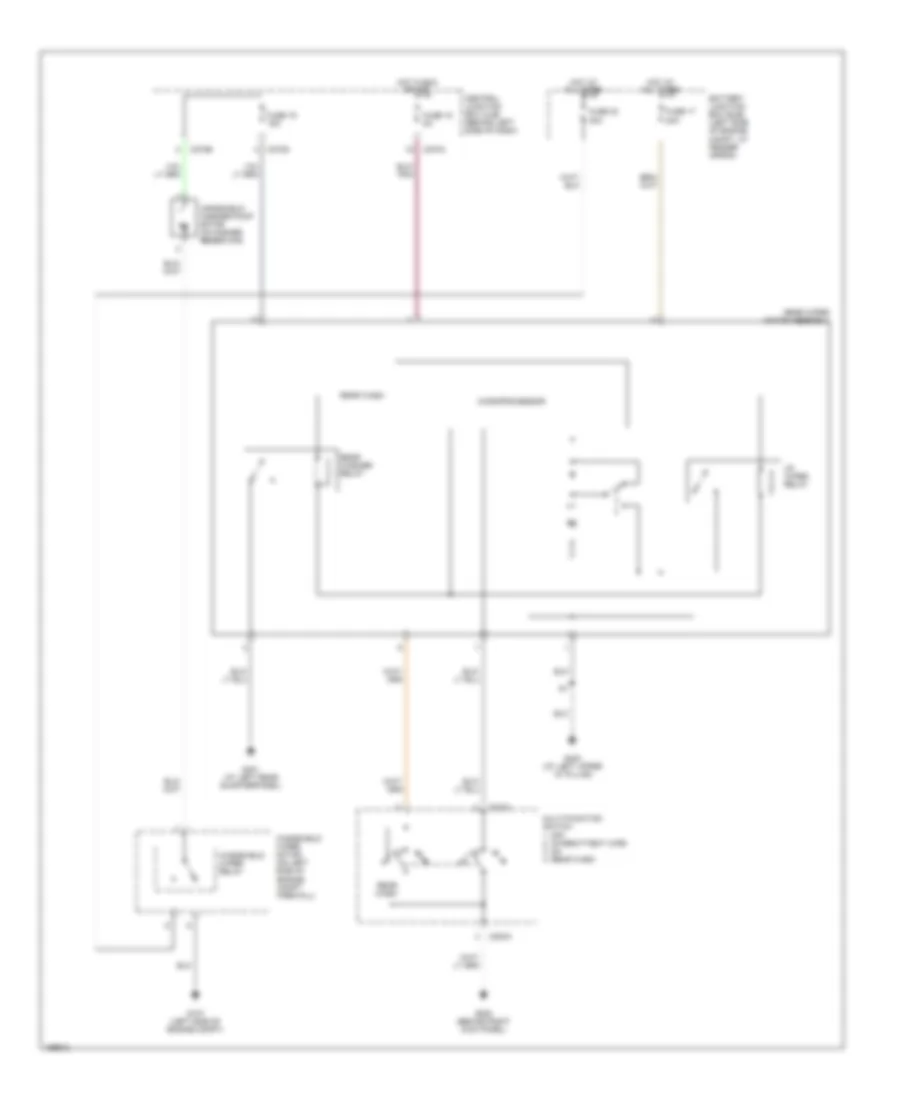
WIPER/WASHER Front Wiper/Washer Wiring Diagram for Lincoln Aviator 2003 List of elements for Front Wiper/Washer Wiring Diagram for Lincoln Aviator 2003: 34 (on left side of engine compt firewall) windshield wiper motor 1. off 2. int 1 3. int 2 4. int 3 5. int 4 6. int 5 7. low 8. high Battery junction box (bjb) (left side of engine compt, at fender apron) C175b C202a C270b C270g Central junction box (cjb) (behind left side of dash) Front wash Fuse 17 20a Fuse 19 15a Fuse 30 30a Fuse 4 5a G105 (left front of engine compt) G107 (left side of engine compt) G203 (under center console) G401 (at left rear quarterpanel) Hall sensor Hi/lo speed relay Hot at all times Hot in run or acc central junction box (cjb) (behind left side of dash) Microprocessor Multi- function switch Off Park sense Powertrain control module (at right side of engine firewall) Rear wiper motor assembly Run/ park Run/ park relay S12 (below battery junction box) Vss out Wash Windshield washer pump motor (in washer reservoir) Windshield washer relay Rear Wiper/Washer Wiring Diagram for Lincoln Aviator 2003 List of elements for Rear Wiper/Washer Wiring Diagram for Lincoln Aviator 2003: 25 Battery junction box (bjb) (left side of engine compt, at fender apron) C202a C270a C270b C270g Central junction box (cjb) (behind left side of dash) Fuse 15 5a Fuse 17 20a Fuse 19 15a Fuse 30 30a G107 (left side of engine compt) G202 (behind right kick panel) G400 (at left upper ``d" pillar) G401 (at left rear quarterpanel) Hot at all times Hot in run or acc Microprocessor Multi-function switch 1. off 2. intermittent wipe 3. on 4. rear wash Rear wash Rear washer relay Rear wiper motor assembly Up wiper relay Windshield washer pump motor (in washer reservoir) Windshield wiper motor (on left side of engine compt firewall) Windshield wiper relay