AIR CONDITIONING
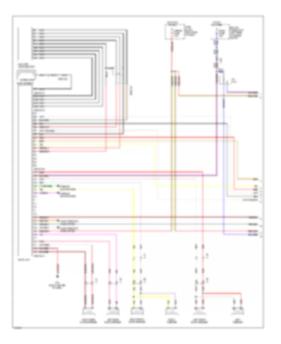
Automatic A/C Wiring Diagram (1 of 2) for Mazda 5 Grand Touring 2014

List of elements for Automatic A/C Wiring Diagram (1 of 2) for Mazda 5 Grand Touring 2014:
- (right side of a/c unit) air intake actuator
- 0740-201a
- 0740-201b
- A/c fuse 10a
- A/c mag fuse 10a
- A/c relay
- Blower relay 1
- Blower relay 2
- C-02
- C-05
- C-66
- Climate control unit
- Computer data lines system
- Front blower motor (center of a/c unit)
- Front power mos fet (lower right side of a/c unit)
- Fuse block (right end of dash)
- G02
- G09 (left side of dash)
- Heater 1 fuse 40a
- Heater 2 fuse 30a
- Heater 3 fuse 30a
- Hot at all times
- Hot in on or start
- Interior lights system
- J/c c-44
- J/c g02
- J/c g09
- Magnetic clutch (on a/c compressor)
- Rear blower motor (under center of dash)
- Rear fan switch
- Rear vent actuator (lower front of a/c unit)
- Red
- Relay & fuse block (left rear of engine compt)
- Room fuse 15a
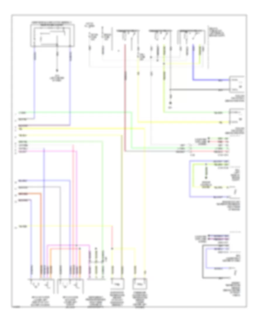
Automatic A/C Wiring Diagram (2 of 2) for Mazda 5 Grand Touring 2014
List of elements for Automatic A/C Wiring Diagram (2 of 2) for Mazda 5 Grand Touring 2014:
- (near rear blower motor assembly) rear power mos fet
- 0140-101a
- 0140-101b
- 0940-101a
- 0940-101f
- 1ai
- 1am
- 2ah
- 2av
- Ad fan fuse 30a
- Air flow mode actuator (lower left side of a/c unit)
- Air mix actuator (lower left side of a/c unit blower housing)
- Ambient temperature sensor (behind center of front fascia)
- Bcm (under right center of dash)
- C-02
- C-05
- Computer data lines system
- Cooling fan motor 1 (behind radiator)
- Cooling fan motor 2 (behind radiator)
- Cooling fan relay 1
- Cooling fan relay 2
- Cooling fan relay 3
- Eng+b fuse 10a
- Engine controls system
- Engine coolant temperature sensor (right rear of engine)
- Evaporator temperature sensor (in a/c unit evaporator assembly)
- Fan1 fuse 30a
- G01
- G12 (left center of dash)
- Hot at all times
- Passenger compartment temperature sensor (under center left of dash)
- Pcm (left rear of engine compt)
- Red
- Refrigerant pressure sensor (right rear corner of engine compt)
- Relay & fuse block (left rear of engine compt)
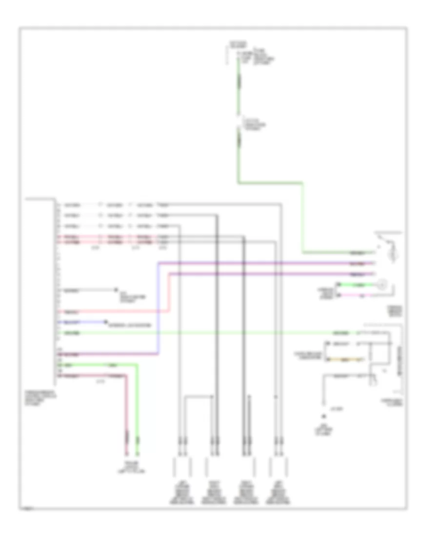
ANTI-LOCK BRAKES
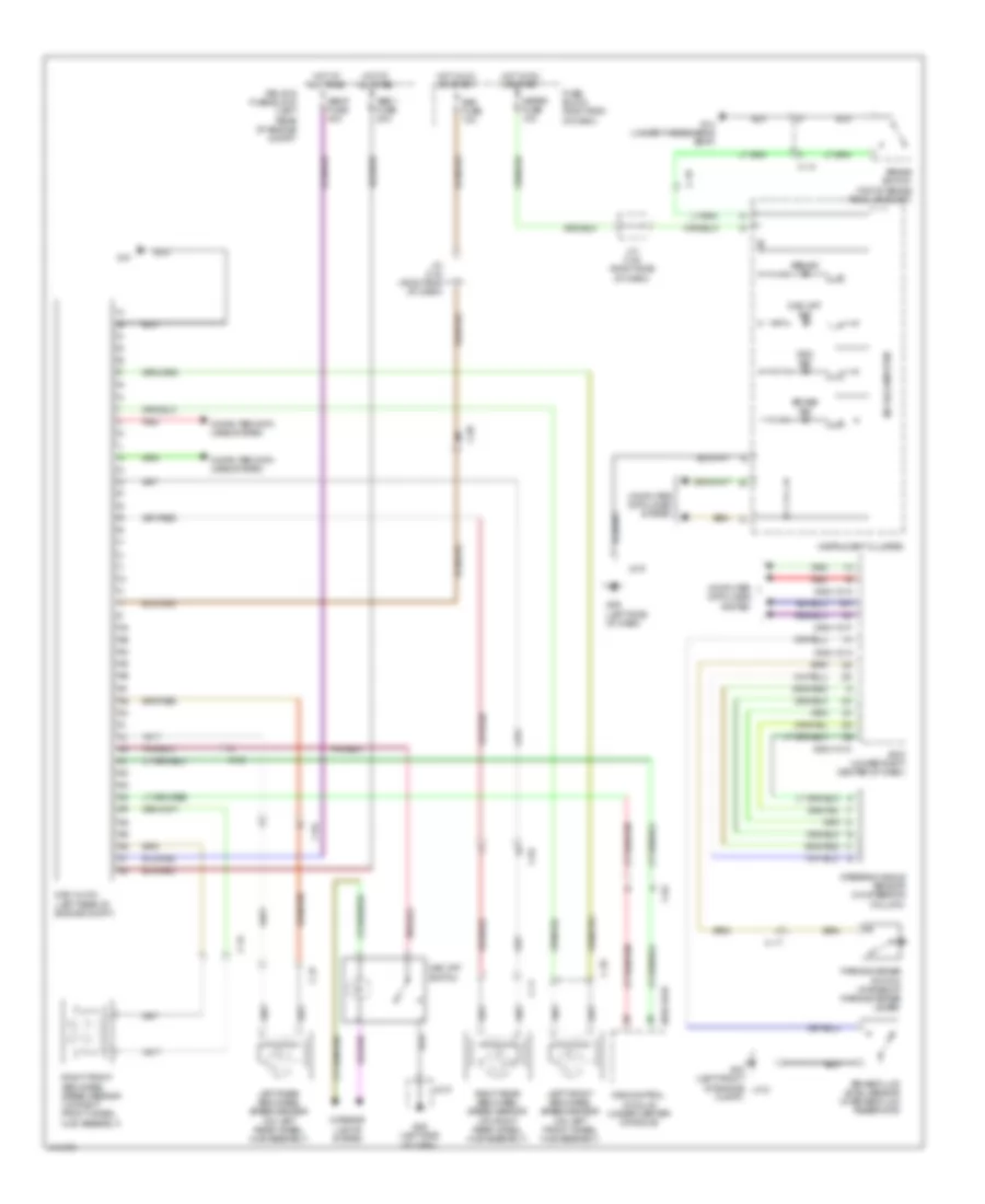
Anti-lock Brakes Wiring Diagram for Mazda 5 Grand Touring 2014
List of elements for Anti-lock Brakes Wiring Diagram for Mazda 5 Grand Touring 2014:
- 0810-101b
- 0940-101a
- 0940-101c
- 0940-101f
- Abs ind
- Abs p fuse 40a
- Abs v fuse 20a
- Bcm (under right center of dash)
- Brake fluid level sensor (in brake fluid reservoir)
- Brake ind
- Brake switch (top of brake pedal bracket)
- C-04
- C-05
- C-10
- C-11
- C-17
- C-18
- C-34
- C-35
- C-37
- Compt)
- Computer data lines system
- Dsc hu/cm (left rear of engine compt)
- Dsc ind
- Dsc off ind
- Dsc off switch
- Fuse block (right end of dash)
- G01
- G02 (left front of engine j/c 2
- G09 (left side of dash)
- G14 (under passenger's seat)
- Hot at all times
- Hot in on or start
- Instrument cluster
- Interior lights system
- J/c 9
- J/c c-42 (right side of dash)
- J/c c-43 (right end of dash)
- Left front abs wheel speed sensor (on left front wheel hub assembly)
- Left rear abs wheel speed sensor (on left rear wheel hub assembly)
- Meter fuse 10a
- Microcomputer
- Parking brake switch (at base of parking brake lever)
- Red
- Relay & fuse block (left rear of engine compt)
- Right front abs wheel speed sensor (on right front wheel hub assembly)
- Right rear abs wheel speed sensor (on right rear wheel hub assembly)
- Sas control module (under center console)
- Sas fuse 10a
- Steering angle sensor (on steering column)
ANTI-THEFT
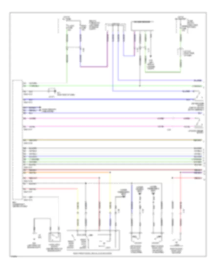
Forced Entry Wiring Diagram (1 of 2) for Mazda 5 Grand Touring 2014
List of elements for Forced Entry Wiring Diagram (1 of 2) for Mazda 5 Grand Touring 2014:
- (if equipped)
- (under driver's seat) g17
- (under passenger's seat) g14
- 0940-101a
- 0940-101c
- 0940-101d
- 0940-101e
- 0940-101f
- Bcm (under right center of dash)
- C-05
- C-17
- C-18
- C-20
- C-30
- C-31
- C-32
- Computer data lines system
- D lock fuse 20a
- Front door latch switch
- Front door lock- link switch
- Fuse block (right end of dash)
- G02 (left front of engine compt)
- G11 (right end of dash)
- G16 (left side of luggage compt)
- Hood latch switch (center front of engine compt)
- Hot at all times
- Hot in on or start
- J/c c-42 (right side of dash)
- J/c c-44
- J/c g02
- J/c g11
- Key reminder switch (part of ignition switch assembly)
- Keyless receiver
- Left sliding door lock-
- Liftgate opener switch
- Link switch
- Lock
- Meter fuse 10a
- Relay & fuse block (left rear of engine compt)
- Right front door latch & lock actuator
- Right sliding door lock actuator
- Right sliding door lock-
- Room fuse 15a
- Unlock
Forced Entry Wiring Diagram (2 of 2) for Mazda 5 Grand Touring 2014
List of elements for Forced Entry Wiring Diagram (2 of 2) for Mazda 5 Grand Touring 2014:
- (left "c" pillar)
- (under
- C-20
- C-29
- C-30
- C-32
- Computer data lines system
- Door ind
- Driver's seat)
- Front door latch switch
- Front door lock- link switch
- G09 (left side of dash)
- G14 (under passenger's seat)
- G16 (left side of
- G17
- G17 (under driver's seat)
- Instrument cluster
- J/c g09
- Key cylinder switch
- Left door lock switch
- Left front door latch & lock actuator
- Left sliding door lock actuator
- Left sliding door switch
- Liftgate lock actuator (bottom center of liftgate)
- Lock
- Luggage compt)
- Microcomputer
- Right door lock switch
- Right sliding door switch (right "c" pillar)
- Security ind
- Unlock
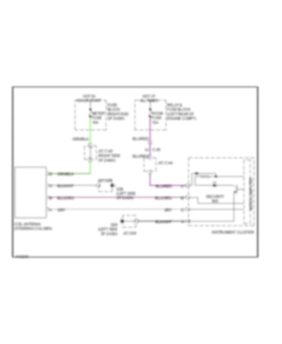
Immobilizer Wiring Diagram for Mazda 5 Grand Touring 2014
List of elements for Immobilizer Wiring Diagram for Mazda 5 Grand Touring 2014:
- (right side of dash)
- Aj c-05
- Coil antenna (steering column)
- Fuse block (right end of dash)
- G09 (left side of dash)
- Hot at all times
- Hot in on or start
- Instrument cluster
- J/c c-42
- J/c c-44
- J/c g09
- Meter fuse 10a
- Microcomputer
- Relay & fuse block (left rear of engine compt)
- Room fuse 15a
- Security ind
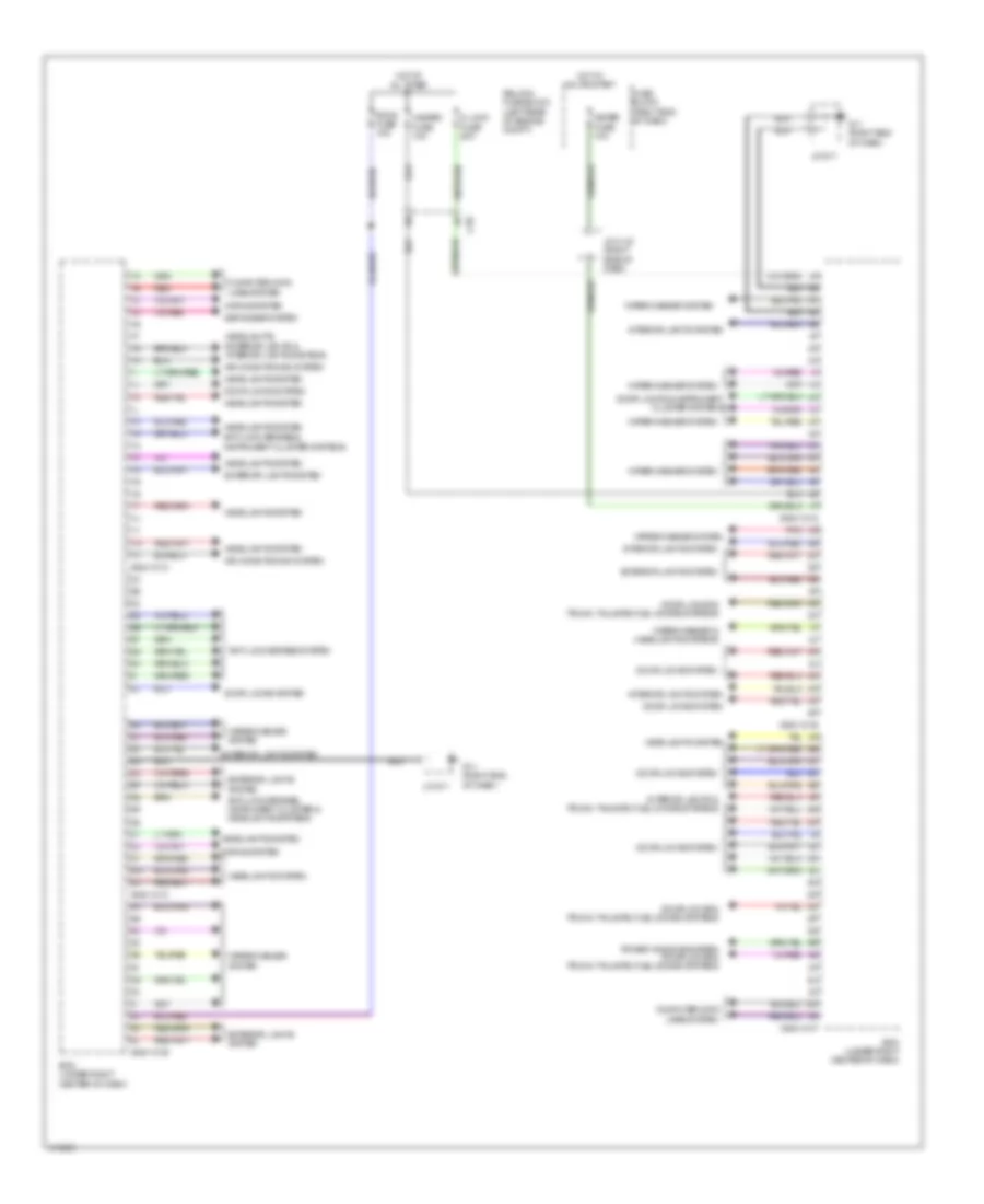
BODY CONTROL MODULES
Body Control Modules Wiring Diagram for Mazda 5 Grand Touring 2014
List of elements for Body Control Modules Wiring Diagram for Mazda 5 Grand Touring 2014:
- 0940-101a
- 0940-101b
- 0940-101c
- 0940-101d
- 0940-101e
- 0940-101f
- Air conditioning system
- Anti-lock brakes & instrument cluster systems
- Anti-lock brakes system
- Anti-lock brakes, instrument cluster & headlights systems
- Bcm (under right center of dash)
- C-05
- Computer data lines system
- D lock fuse 20a
- Defogger system
- Door locks & instrument cluster systems
- Door locks & trunk, tailgate, fuel doors systems
- Door locks system
- Exterior lights system
- Fuse block (right end of dash)
- G11 (right end of dash)
- Hazard fuse 10a
- Headlights system
- Headlights, exterior lights & interior lights systems
- Horns system
- Hot at all times
- Hot in on or start
- Interior lights & trunk, tailgate, fuel doors systems
- Interior lights system
- J/c c-42 (right side of dash)
- J/c g11
- Meter fuse 10a
- Pnk
- Power windows system door locks & trunk, tailgate, fuel doors systems
- Red
- Relay & fuse block (left rear of engine compt)
- Room fuse 15a
- Wiper/washer & headlights systems
- Wiper/washer system
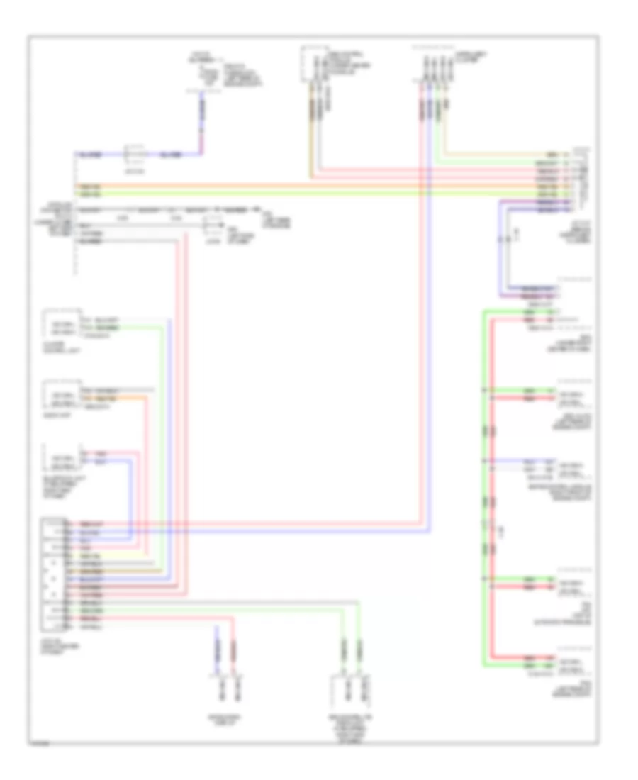
COMPUTER DATA LINES
Computer Data Lines Wiring Diagram for Mazda 5 Grand Touring 2014
List of elements for Computer Data Lines Wiring Diagram for Mazda 5 Grand Touring 2014:
- 0140-101a
- 0614-101b
- 0740-201a
- 0810-101a
- 0920-201a
- 0940-101a
- 0940-101f
- 1ai
- 1am
- Audio unit
- Bcm (under right center of dash)
- C-02
- C-05
- C-18
- Climate control unit
- Data link connector (dlc) 2 (under lower left side of dash)
- Dsc hu/cm (left rear of engine compt)
- Ehpas control module (right front of engine compt)
- G09 (left side of dash)
- G23 (left rear of engine)
- Hot at all times
- Hs can-h
- Hs can-l
- Information display
- Instrument cluster
- J/c 09
- J/c c-44
- J/c c-45 (right center of dash)
- J/c c-47 (behind instrument cluster)
- Ms can-h
- Ms can-l
- Pcm (left rear of engine compt)
- Pnk
- Red
- Relay & fuse block (left rear of engine compt)
- Room fuse 15a
- Sas control module (under center console)
- Sirius satellite radio unit (if equipped) (right end of dash)
- Tcm (a/t) (top of automatic transaxle)
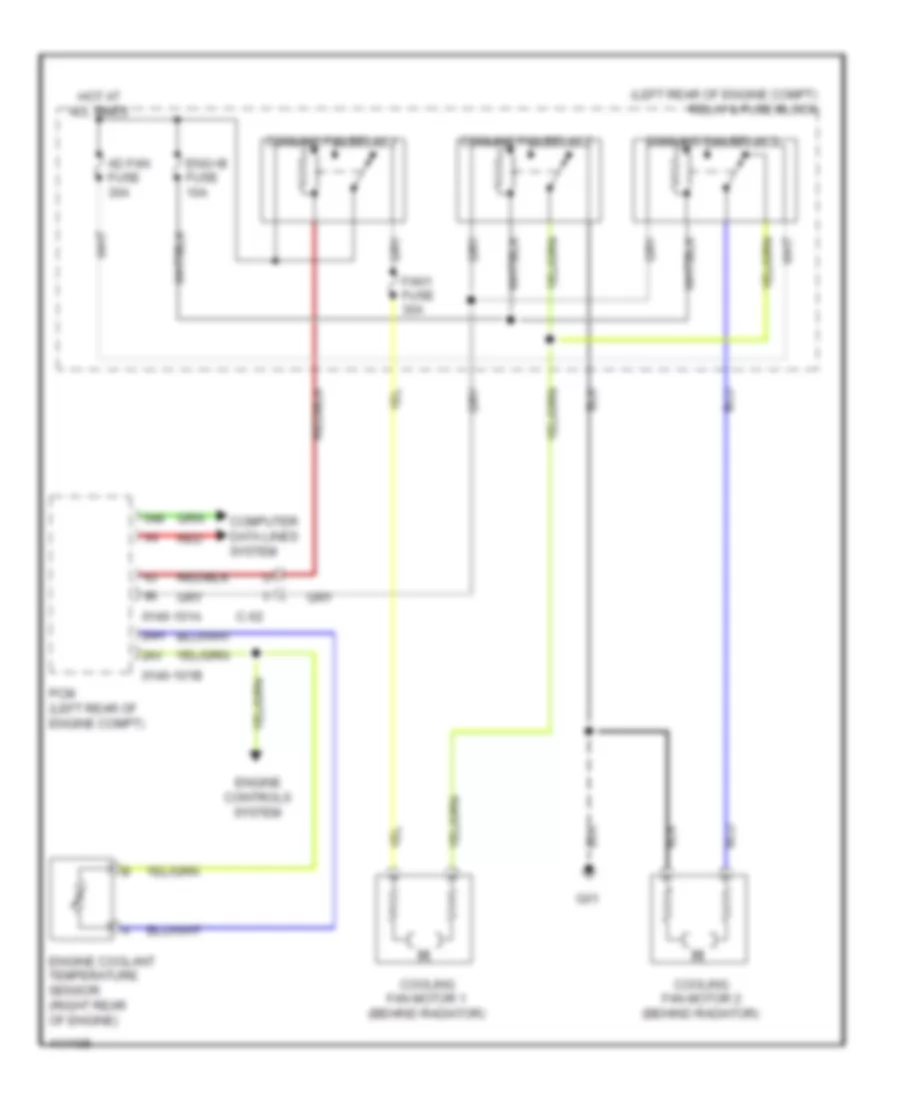
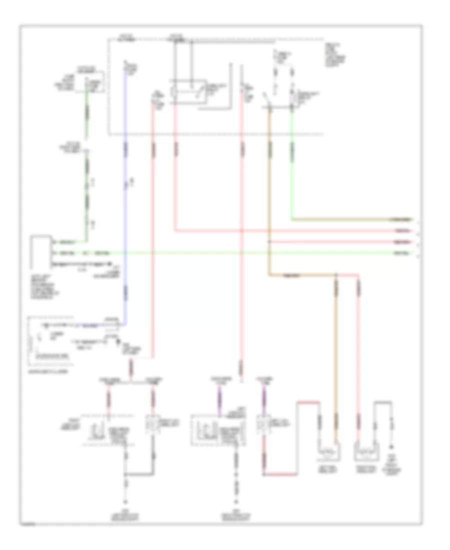
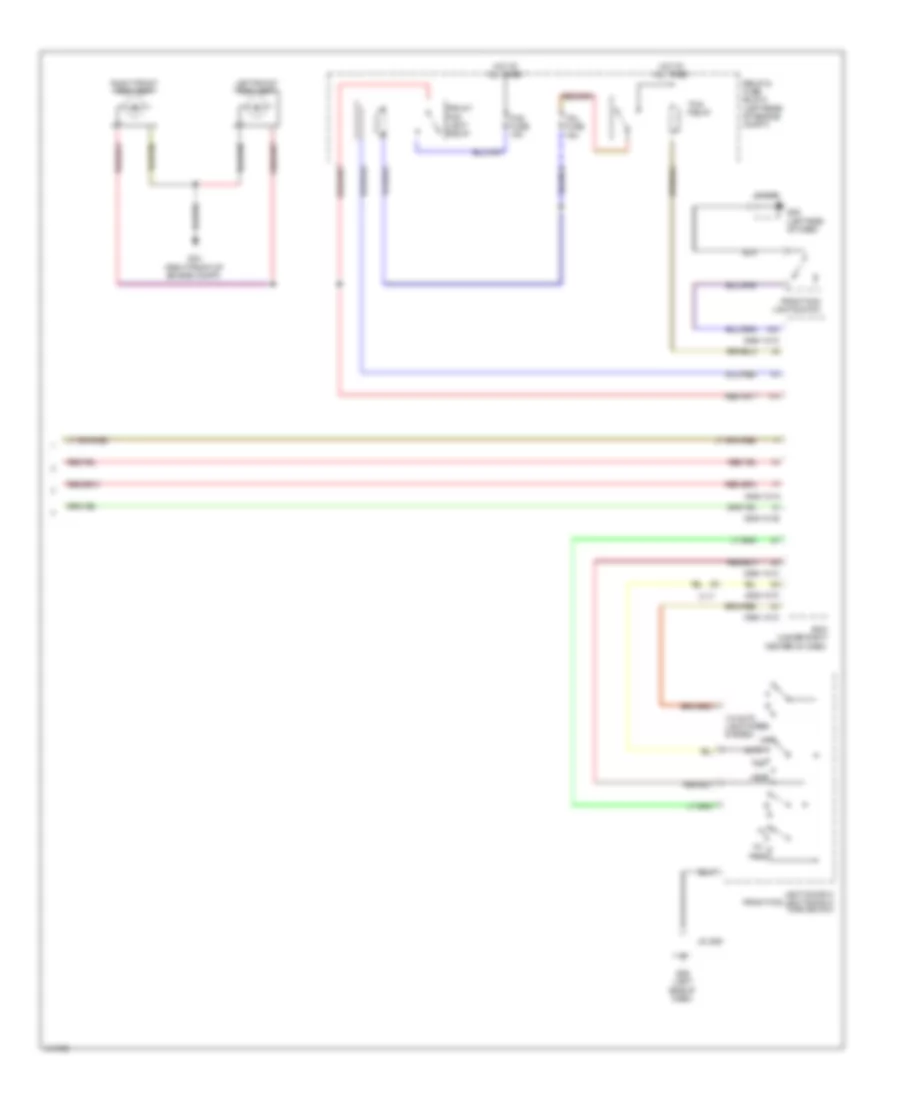
COOLING FAN
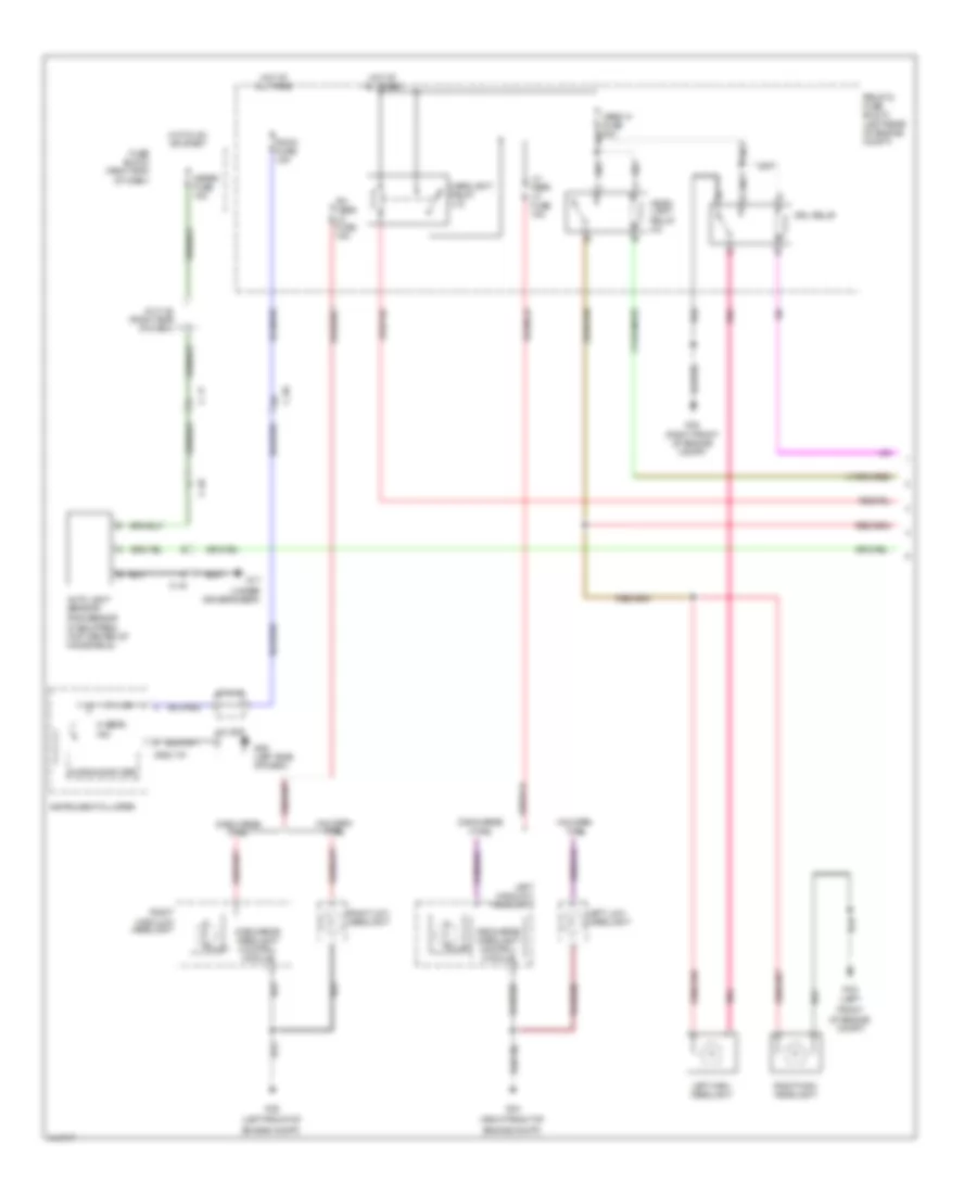
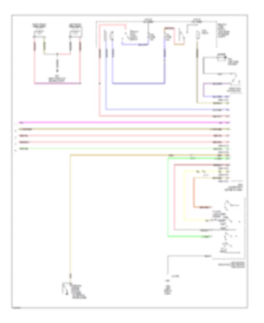
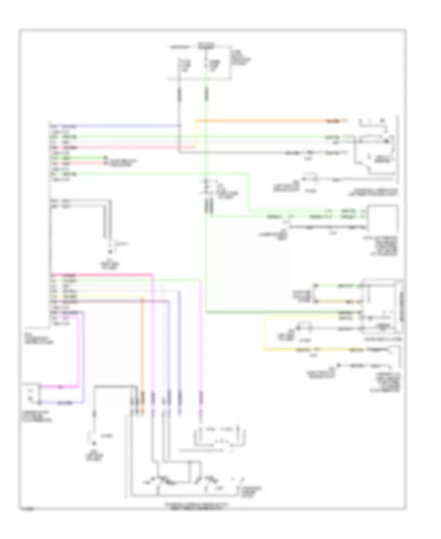
Cooling Fan Wiring Diagram for Mazda 5 Grand Touring 2014
List of elements for Cooling Fan Wiring Diagram for Mazda 5 Grand Touring 2014:
- (left rear of engine compt) relay & fuse block
- 0140-101a
- 0140-101b
- 1ai
- 1am
- 2ah
- 2av
- Ad fan fuse 30a
- C-02
- Computer data lines system
- Cooling fan motor 1 (behind radiator)
- Cooling fan motor 2 (behind radiator)
- Cooling fan relay 1
- Cooling fan relay 2
- Cooling fan relay 3
- Eng+b fuse 10a
- Engine controls system
- Engine coolant temperature sensor (right rear of engine)
- Fan1 fuse 30a
- G01
- Hot at all times
- Pcm (left rear of engine compt)
- Red
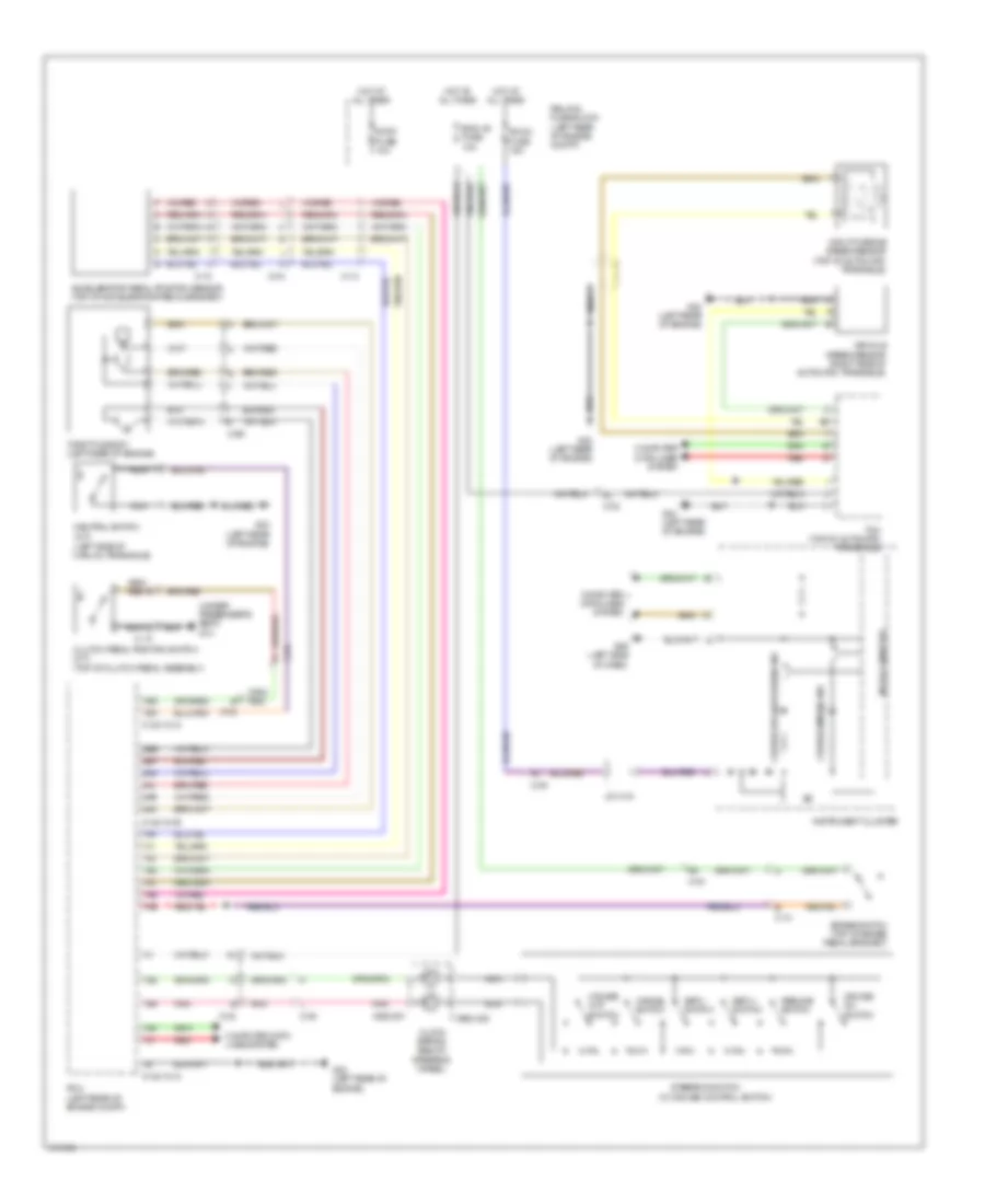
CRUISE CONTROL
Cruise Control Wiring Diagram for Mazda 5 Grand Touring 2014
List of elements for Cruise Control Wiring Diagram for Mazda 5 Grand Touring 2014:
- (left side of manual transaxle)
- (under passenger's seat) g14
- (w/ cruise control switch)
- 0140-101a
- 0140-101b
- 0922-201
- 0922-202
- 1ab
- 1ae
- 1ai
- 1aj
- 1am
- 1an
- 1ao
- 1ap
- 1aq
- 1av
- 1bc
- 1bd
- 2ak
- 2al
- 2an
- 2ar
- 2be
- 2bf
- Accelerator pedal position sensor (top of accelerator pedal bracket)
- Brake switch (top of brake pedal bracket)
- C-02
- C-04
- C-05
- C-10
- C-13
- C-69
- Cancel switch
- Clock spring (below steering wheel)
- Clutch pedal position switch (m/t) (top of clutch pedal assembly)
- Computer data lines system
- Cruise (amber) ind
- Cruise off switch
- Cruise on switch
- Eng +b fuse 10a
- G09 (left side of dash)
- G23 (left rear of engine)
- Hot at all times
- Input/turbine speed sensor (top of automatic transaxle)
- Instrument cluster
- J/c c-44
- Microcomputer
- Nca
- Neutral switch (m/t)
- Pcm (left rear of engine compt)
- Pnk
- Red
- Relay & fuse block (left rear of engine compt)
- Resume switch
- Room fuse 15a
- Set(+) switch
- Set(-) switch
- Steering switch
- Stop fuse 10a
- Tcm (top of automatic transaxle)
- Throttle body (left rear of engine)
- Vehicle speed sensor (right side of automatic transaxle)
DEFOGGERS
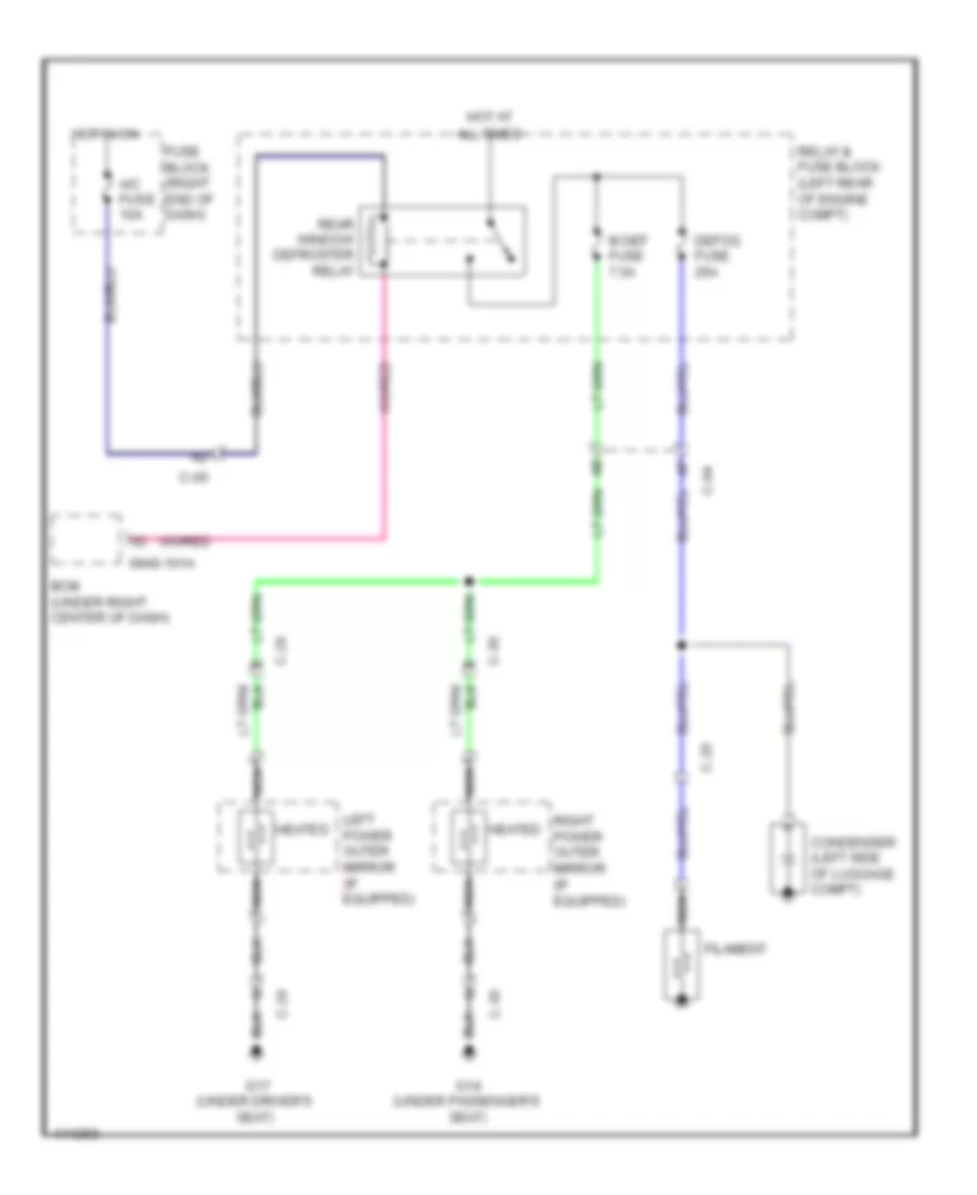
Defoggers Wiring Diagram for Mazda 5 Grand Touring 2014
List of elements for Defoggers Wiring Diagram for Mazda 5 Grand Touring 2014:
- 0940-101a
- A/c fuse 10a
- All times
- Bcm (under right center of dash)
- C-04
- C-05
- C-20
- C-29
- C-30
- Condenser (left side of luggage compt)
- Defog fuse 25a
- Filament
- Fuse block (right end of dash)
- G14 (under passenger's seat)
- G17 (under driver's seat)
- Heated
- Hot at
- Hot in on
- Left power outer mirror (if equipped)
- M def fuse 7.5a
- Nca
- Rear window defroster relay
- Relay & fuse block (left rear of engine compt)
- Right power outer mirror (if equipped)
ELECTRONIC POWER STEERING
Electronic Power Steering Wiring Diagram for Mazda 5 Grand Touring 2014
List of elements for Electronic Power Steering Wiring Diagram for Mazda 5 Grand Touring 2014:
- (right front
- 0614-101a
- 0614-101b
- C-05
- Compt)
- Computer data lines system
- Ehpas control module (right front of engine compt)
- Ehpas fuse 5a
- Ehpas fuse 80a
- Ehpas ind
- Fuse block (right end of dash)
- G05
- G09 (left side of dash)
- Hot at all times
- Hot in run or start
- Instrument cluster
- J/c c-42 (right side of dash)
- Meter fuse 10a
- Micro computer
- Of engine
- Relay & fuse block (left rear of engine compt)
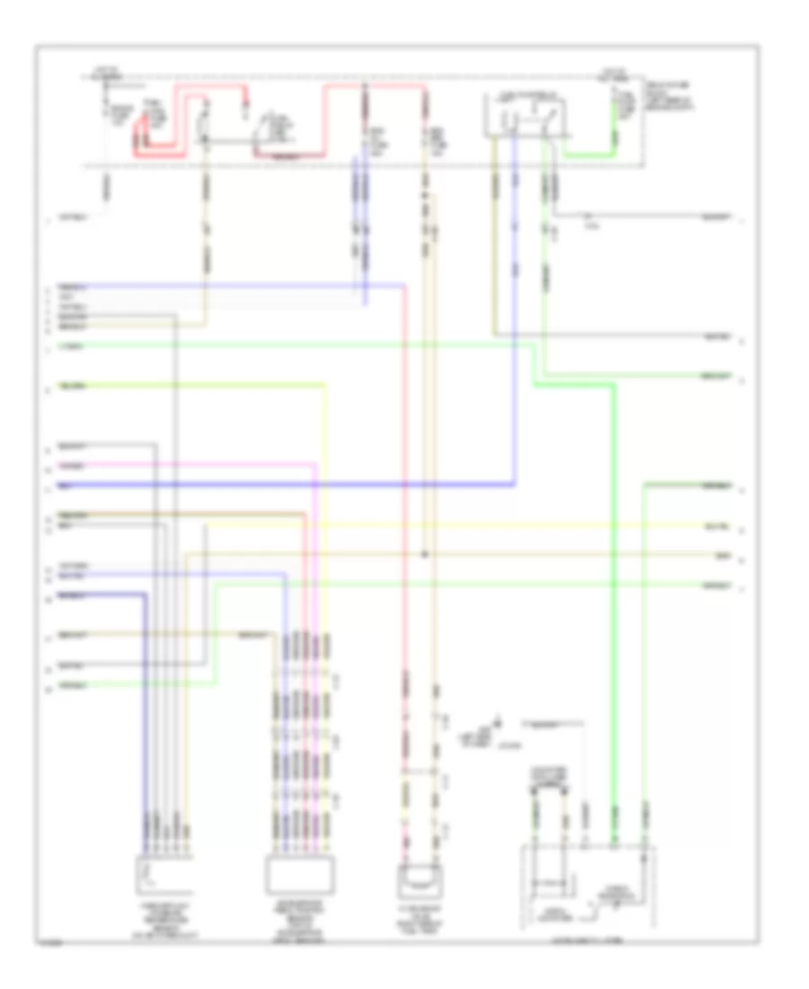
ENGINE PERFORMANCE
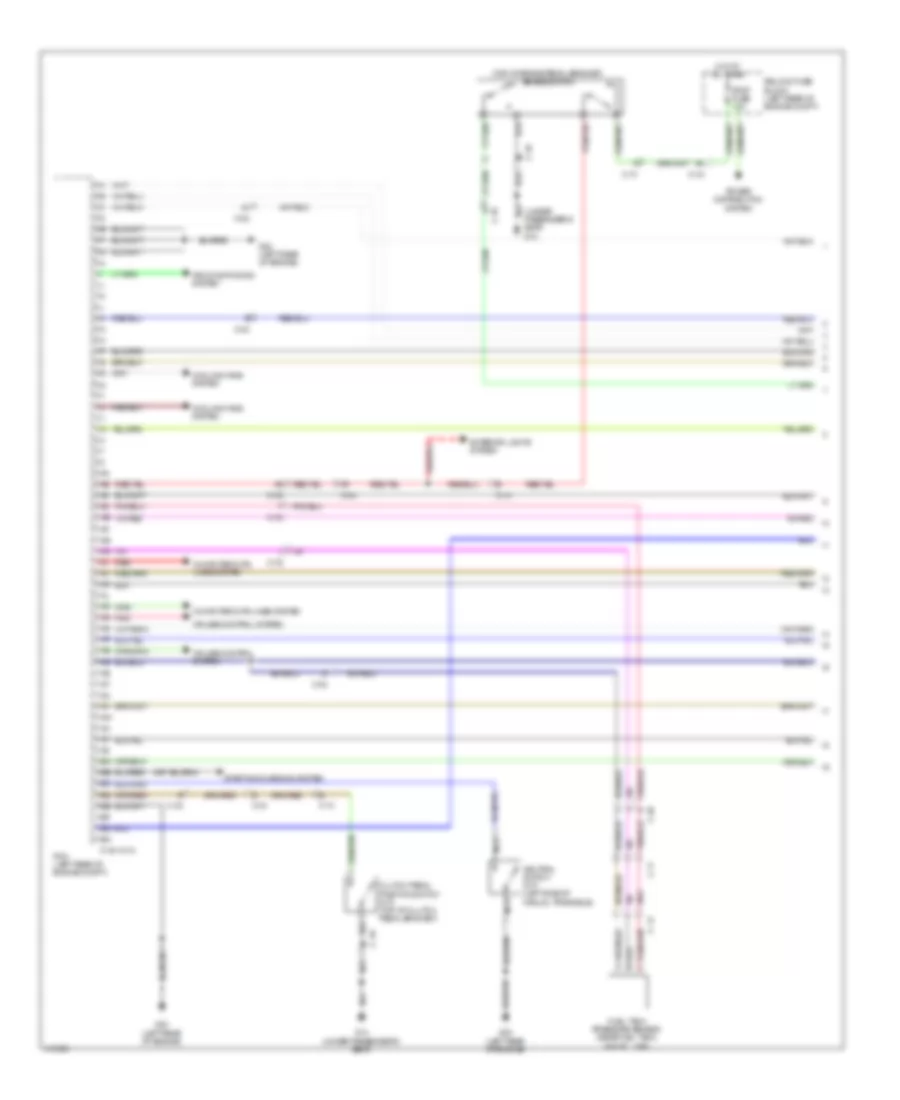
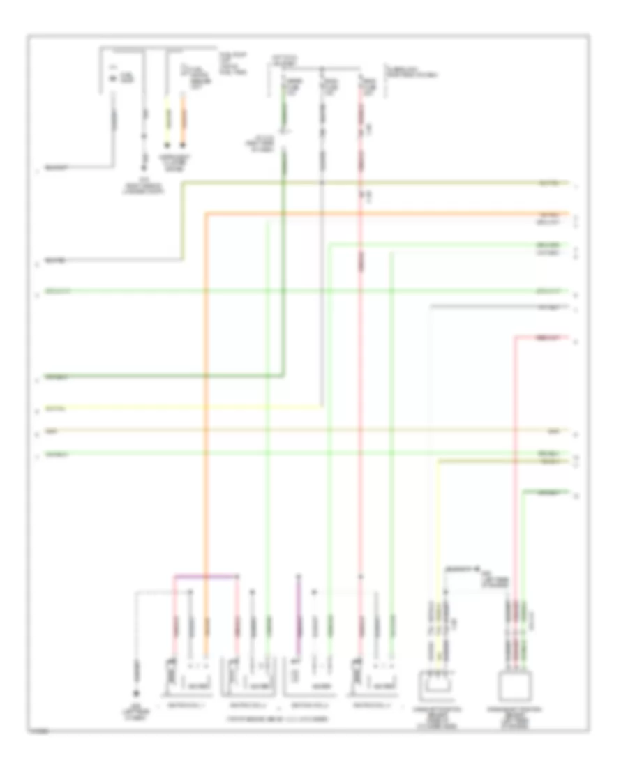
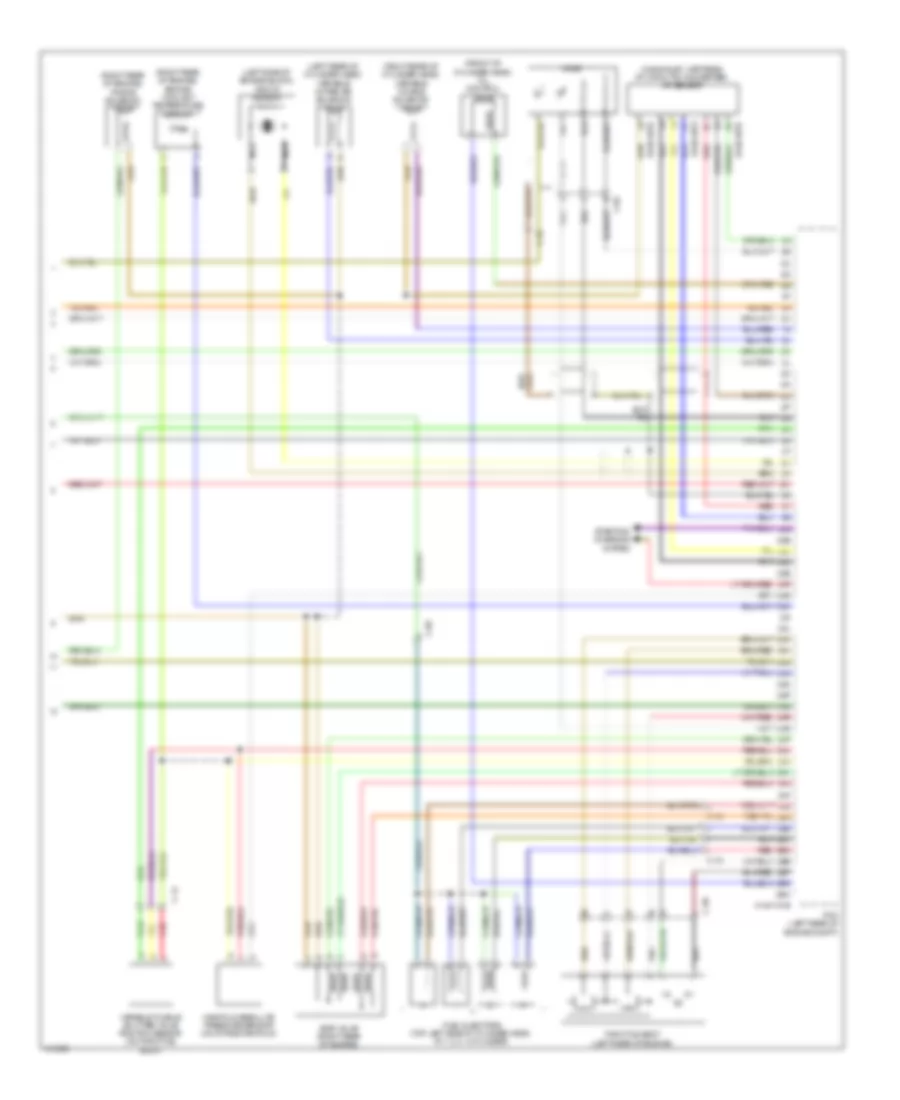
Engine Performance Wiring Diagram (1 of 4) for Mazda 5 Grand Touring 2014
List of elements for Engine Performance Wiring Diagram (1 of 4) for Mazda 5 Grand Touring 2014:
- (top of brake pedal bracket) brake switch
- (under passenger's seat) g14
- 0140-101a
- 1aa
- 1ab
- 1ac
- 1ad
- 1ae
- 1af
- 1ag
- 1ah
- 1ai
- 1aj
- 1ak
- 1al
- 1am
- 1an
- 1ao
- 1ap
- 1aq
- 1ar
- 1as
- 1at
- 1au
- 1av
- 1aw
- 1ax
- 1ay
- 1az
- 1ba
- 1bb
- 1bc
- 1bd
- 1be
- 1bf
- 1bg
- 1bh
- Air conditioning system
- C-02
- C-04
- C-10
- C-11
- C-12
- C-18
- Clutch pedal position switch (m/t) (top of clutch pedal bracket)
- Computer data lines system
- Cooling fans system
- Cruise control system
- Exterior lights system
- Fuel tank pressure sensor (near fuel tank, in fuel line)
- G14 (under passenger's seat)
- G23 (left rear of engine)
- Hot at all times
- Nca
- Neutral switch (m/t) (left side of manual transaxle)
- Pcm (left rear of engine compt)
- Pnk
- Power distribution system
- Red
- Relay & fuse block (left rear of engine compt)
- Starting/charging system
- Stop fuse 10a
Engine Performance Wiring Diagram (2 of 4) for Mazda 5 Grand Touring 2014
List of elements for Engine Performance Wiring Diagram (2 of 4) for Mazda 5 Grand Touring 2014:
- Accelerator pedal position sensor (top of accelerator pedal bracket)
- C-02
- C-04
- C-10
- C-11
- C-12
- C-13
- Check engine ind
- Computer data lines system
- Cv solenoid valve (right side of fuel tank)
- Eg1 main fuse 40a
- Eng bar fuse 15a
- Eng inj fuse 25a
- Eng+b fuse 10a
- Fuel pump fuse 20a
- Fuel pump relay
- G09 (left side of dash)
- Hot at all times
- Instrument cluster
- J/c g09
- Main relay (egi main 1)
- Mass air flow/ intake air temperature sensor (on air intake duct)
- Micro- computer
- Pnk
- Red
- Relay & fuse block (left rear of engine compt)
Engine Performance Wiring Diagram (3 of 4) for Mazda 5 Grand Touring 2014
List of elements for Engine Performance Wiring Diagram (3 of 4) for Mazda 5 Grand Touring 2014:
- (top of engine, above 1, 2, 3, 4 cylinder)
- 014-141
- C-02
- C-05
- C-69
- Camshaft position sensor (rear of cylinder head)
- Crankshaft position sensor (left rear of engine)
- Eng2 fuse 15a
- Eng3 fuse 20a
- Fuel gauge sender unit
- Fuel pump
- Fuel pump unit (top of fuel tank)
- Fuse block (right end of dash)
- G15 (right side of luggage compt)
- G29 (left rear of engine)
- G29 (left rear of seat)
- Hot in on or start
- Igniter
- Ignition coil 1
- Ignition coil 2
- Ignition coil 3
- Ignition coil 4
- Instrument cluster system
- J/c c-42 (right side of dash)
- Meter fuse 10a
Engine Performance Wiring Diagram (4 of 4) for Mazda 5 Grand Touring 2014
List of elements for Engine Performance Wiring Diagram (4 of 4) for Mazda 5 Grand Touring 2014:
- (front of cylinder head) oil control valve
- (in exhaust, upstream of catalytic converter) a/f sensor
- (left rear of cylinder head) variable intake air solenoid valve
- (left side of engine block) knock sensor
- (right rear of cylinder head) variable tumble solenoid valve
- (right rear of engine) engine coolant temperature sensor
- (right rear of engine) purge solenoid valve
- 0140-101b
- 0140-107a
- 0140-107b
- 2aa
- 2ab
- 2ac
- 2ad
- 2ae
- 2af
- 2ag
- 2ah
- 2ai
- 2aj
- 2ak
- 2al
- 2am
- 2an
- 2ao
- 2ap
- 2aq
- 2ar
- 2as
- 2at
- 2au
- 2av
- 2aw
- 2ax
- 2ay
- 2az
- 2ba
- 2bb
- 2bc
- 2bd
- 2be
- 2bf
- 2bg
- 2bh
- C-02
- C-14
- C-69
- Egr valve (right rear of engine)
- Fuel injectors (top left side of cylinder head, at 1, 2, 3, 4 cylinder)
- Ho2s
- Manifold absolute pressure sensor (on intake manifold)
- Nca
- Pcm (left rear of engine compt)
- Red
- Starting/ charging system
- Throttle body (left rear of engine)
- Variable tumble shutter valve position sensor (on throttle body)
2.5L
2.5L, Engine Performance Wiring Diagram (1 of 4) for Mazda 5 Grand Touring 2014
List of elements for 2.5L, Engine Performance Wiring Diagram (1 of 4) for Mazda 5 Grand Touring 2014:
- (top of brake pedal bracket) brake switch
- (under passenger's seat) g14
- 0140-101a
- 1aa
- 1ab
- 1ac
- 1ad
- 1ae
- 1af
- 1ag
- 1ah
- 1ai
- 1aj
- 1ak
- 1al
- 1am
- 1an
- 1ao
- 1ap
- 1aq
- 1ar
- 1as
- 1at
- 1au
- 1av
- 1aw
- 1ax
- 1ay
- 1az
- 1ba
- 1bb
- 1bc
- 1bd
- 1be
- 1bf
- 1bg
- 1bh
- Air conditioning system
- C-02
- C-04
- C-10
- C-11
- C-12
- C-18
- Clutch pedal position switch (m/t) (top of clutch pedal bracket)
- Computer data lines system
- Cooling fans system
- Cruise control system
- Exterior lights system
- Fuel tank pressure sensor (near fuel tank, in fuel line)
- G14 (under passenger's seat)
- G23 (left rear of engine)
- Hot at all times
- Nca
- Neutral switch (m/t) (left side of manual transaxle)
- Pcm (left rear of engine compt)
- Pnk
- Power distribution system
- Red
- Relay & fuse block (left rear of engine compt)
- Starting/charging system
- Stop fuse 10a
2.5L, Engine Performance Wiring Diagram (2 of 4) for Mazda 5 Grand Touring 2014
List of elements for 2.5L, Engine Performance Wiring Diagram (2 of 4) for Mazda 5 Grand Touring 2014:
- Accelerator pedal position sensor (top of accelerator pedal bracket)
- C-02
- C-04
- C-10
- C-11
- C-12
- C-13
- Check engine ind
- Computer data lines system
- Cv solenoid valve (right side of fuel tank)
- Eg1 main fuse 40a
- Eng bar fuse 15a
- Eng inj fuse 25a
- Eng+b fuse 10a
- Fuel pump fuse 20a
- Fuel pump relay
- G09 (left side of dash)
- Hot at all times
- Instrument cluster
- J/c g09
- Main relay (egi main 1)
- Mass air flow/ intake air temperature sensor (on air intake duct)
- Micro- computer
- Pnk
- Red
- Relay & fuse block (left rear of engine compt)
2.5L, Engine Performance Wiring Diagram (3 of 4) for Mazda 5 Grand Touring 2014
List of elements for 2.5L, Engine Performance Wiring Diagram (3 of 4) for Mazda 5 Grand Touring 2014:
- (top of engine, above 1, 2, 3, 4 cylinder)
- 014-141
- C-02
- C-05
- C-69
- Camshaft position sensor (rear of cylinder head)
- Crankshaft position sensor (left rear of engine)
- Eng2 fuse 15a
- Eng3 fuse 20a
- Fuel gauge sender unit
- Fuel pump
- Fuel pump unit (top of fuel tank)
- Fuse block (right end of dash)
- G15 (right side of luggage compt)
- G29 (left rear of engine)
- G29 (left rear of seat)
- Hot in on or start
- Igniter
- Ignition coil 1
- Ignition coil 2
- Ignition coil 3
- Ignition coil 4
- Instrument cluster system
- J/c c-42 (right side of dash)
- Meter fuse 10a
2.5L, Engine Performance Wiring Diagram (4 of 4) for Mazda 5 Grand Touring 2014
List of elements for 2.5L, Engine Performance Wiring Diagram (4 of 4) for Mazda 5 Grand Touring 2014:
- (front of cylinder head) oil control valve
- (in exhaust, upstream of catalytic converter) a/f sensor
- (left rear of cylinder head) variable intake air solenoid valve
- (left side of engine block) knock sensor
- (right rear of cylinder head) variable tumble solenoid valve
- (right rear of engine) engine coolant temperature sensor
- (right rear of engine) purge solenoid valve
- 0140-101b
- 0140-107a
- 0140-107b
- 2aa
- 2ab
- 2ac
- 2ad
- 2ae
- 2af
- 2ag
- 2ah
- 2ai
- 2aj
- 2ak
- 2al
- 2am
- 2an
- 2ao
- 2ap
- 2aq
- 2ar
- 2as
- 2at
- 2au
- 2av
- 2aw
- 2ax
- 2ay
- 2az
- 2ba
- 2bb
- 2bc
- 2bd
- 2be
- 2bf
- 2bg
- 2bh
- C-02
- C-14
- C-69
- Egr valve (right rear of engine)
- Fuel injectors (top left side of cylinder head, at 1, 2, 3, 4 cylinder)
- Ho2s
- Manifold absolute pressure sensor (on intake manifold)
- Nca
- Pcm (left rear of engine compt)
- Red
- Starting/ charging system
- Throttle body (left rear of engine)
- Variable tumble shutter valve position sensor (on throttle body)
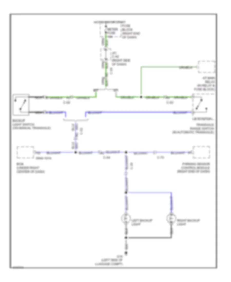
EXTERIOR LIGHTS
Backup Lamps Wiring Diagram for Mazda 5 Grand Touring 2014
List of elements for Backup Lamps Wiring Diagram for Mazda 5 Grand Touring 2014:
- 0940-101a
- A/t
- A/t main relay (in relay & fuse block)
- Backup light switch (on manual transaxle)
- Bcm (under right center of dash)
- C-02
- C-04
- C-05
- C-20
- C-70
- Fuse block (right end of dash)
- G16 (left side of luggage compt)
- Hot in on or start
- J/c c-42 (right side of dash)
- Left backup light
- M/t
- Meter fuse 10a
- Nca
- Parking sensor control module (right end of dash)
- R position
- Right backup light
- Transaxle range switch (in automatic transaxle)
Exterior Lamps Wiring Diagram (1 of 2) for Mazda 5 Grand Touring 2014
List of elements for Exterior Lamps Wiring Diagram (1 of 2) for Mazda 5 Grand Touring 2014:
- 0140-101a
- 1ab
- Brake switch (top of brake pedal bracket)
- C-02
- C-04
- C-10
- C-17
- C-20
- C-29
- C-30
- Computer data lines system
- Fuse block (right end of dash)
- G09 (left side of dash)
- G14 (under passenger's seat)
- G15 (right side of
- G16 (left side of luggage compt)
- G17 (under driver's seat)
- High-mount brake light
- Hot at all times
- Hot in on or start
- Instrument cluster
- J/c c-42 (right side of dash)
- J/c g09
- Left brake light
- Left front side turn light (if equipped)
- Left license plate light
- Left rear turn light
- Left tail light
- Left tail light/ left brake light/ left rear turn light
- Left turn ind
- Luggage compt)
- Meter fuse 10a
- Microcomputer
- Nca
- Pcm (left rear of engine compt)
- Power distribution system
- Relay & fuse block (left rear of engine compt)
- Right brake light
- Right front side turn light (if equipped)
- Right license plate light
- Right rear turn light
- Right tail light
- Right tail light/ right brake light/ right rear turn light
- Right turn ind
- Selector lever component (a/t) (base of shift lever assembly)
- Stop fuse 10a
Exterior Lamps Wiring Diagram (2 of 2) for Mazda 5 Grand Touring 2014
List of elements for Exterior Lamps Wiring Diagram (2 of 2) for Mazda 5 Grand Touring 2014:
- 0940-101a
- 0940-101b
- 0940-101c
- 0940-101d
- 0940-101e
- 0940-101f
- All times
- Bcm (under right center of dash)
- C-05
- Can-h
- Can-l
- Computer data lines system
- G02 (left front of engine compt)
- G09 (left side of dash)
- G11 (right end of dash)
- Hazard fuse 10a
- Hazard warning switch
- Headlights system
- Hot at
- Hot at all times
- Ill
- Interior lights system
- J/c g02
- J/c g09
- J/c g11
- Left
- Left front turn light
- Left parking/ front side marker light
- Left parking/front side marker light/left front turn light
- Light switch/ front fog light switch/ turn switch
- Relay & fuse block (left rear of engine compt)
- Right
- Right front turn light
- Right parking/ front side marker light
- Right parking/front side marker light/right front turn light
- Tns relay (tns)
- Turn switch
GROUND DISTRIBUTION
Ground Distribution Wiring Diagram (1 of 2) for Mazda 5 Grand Touring 2014
List of elements for Ground Distribution Wiring Diagram (1 of 2) for Mazda 5 Grand Touring 2014:
- Bcm, selector level component, front power mos fet, information display & hazard warning switch
- Data link connector 2, light switch, dsc off switch, clock spring, front power mos fet, climate control unit, instrument cluster, turn switch, front fog light switch, windshield wiper & washer switch/rear wiper & washer switch, front accessory socket & coil antenna
- Drl relay (if equipped), left high headlight, left low headlight (halogen), left hi/lo headlight (discharge), washer fluid level sensor (if equipped), cooling fan motor 2 & cooling fan relay 2, left front fog light & right front fog light
- Dsc hu/cm, cooling fan motor 2 & cooling fan relay 2
- Ehpas control module
- G01
- G02 (left front of engine compt)
- G04 (right front of engine compt)
- G05 (right front of engine compt)
- G09 (left side of dash)
- G11 (right end of dash)
- G12 (left center of dash)
- G16 (left side of luggage compt)
- G17 (under driver's seat)
- If equipped
- J/c g02
- J/c g09
- J/c g11
- Left front side turn light (built into outer mirror) (if equipped), left door lock switch, left front door latch & lock actuator, left sliding door lock link switch (if equipped), power window main switch, auto light sensor/ rain sensor (w/ auto light/ wiper system), left heated outer mirror (if equipped), left seat warmer unit & sunroof motor
- Light, right parking /front side marker light, blower relay 1 & 2 & hood latch switch
- Right high headlight, right low headlight (halogen), right hi/low headlight (discharge), brake fluid level sensor, left front turn light, right front turn light, windshield wiper motor, cooling fan motor 2 & cooling fan relay 2, left parking/front side marker
- Sas control module, rear power mos fet, driver side buckle switch, passenger side buckle switch, seat weight sensor control module, sas control module shield & front power mos fet
- Sunroof
Ground Distribution Wiring Diagram (2 of 2) for Mazda 5 Grand Touring 2014
List of elements for Ground Distribution Wiring Diagram (2 of 2) for Mazda 5 Grand Touring 2014:
- A/t
- Battery
- Crankshaft position sensor, ignition coils 1, 2, 3, 4 & camshaft position sensor
- Data link connector 2, tcm, intermediate sensor, vehicle speed sensor, input/turbine speed sensor shield, neutral switch (m/t) & pcm
- G10 (right center of dash)
- G14 (under passenger's seat)
- G15 (right side of luggage compt)
- G19 (a/t) (in automatic transaxle control unit)
- G20 (a/t) (in automatic transaxle control unit)
- G23 (left rear of engine)
- G29 (left rear of engine)
- G32 (right side of engine compt)
- G33 (right side of engine compt)
- G34 (center rear of roof)
- G35 (center rear of roof)
- G36 (left rear of engine compt)
- G37
- If equipped
- Pressure control solenoid
- Right front side turn light (built into outer mirror) (if equipped), right sliding door lock link switch (if equipped), clutch pedal position switch (m/t), right door lock switch, right front door latch & lock actuator, brake switch, right heated outer mirror (if equipped), right seat warmer unit, right seat warmer switch & left seat warmer switch
- Right rear turn light, right brake light, fuel pump unit, right seat warmer unit & right taillight
- Shift solenoid a, b & c
- System
- Unit
- W/ parking sensor
- W/ seat warmer
- W/ sirius satellite radio unit
HEADLIGHTS
Headlights Wiring Diagram, with DRL (1 of 2) for Mazda 5 Grand Touring 2014
List of elements for Headlights Wiring Diagram, with DRL (1 of 2) for Mazda 5 Grand Touring 2014:
- (if equipped) (top center of windshield)
- (left
- (left front of
- (right front of
- (right front of engine compt)
- (under driver's seat)
- 0922-101
- Auto light sensor/ rain sensor
- C-05
- C-17
- C-40
- Discharge headlight control module
- Discharge type
- Drl relay
- Engine compt)
- Front of engine compt)
- Fuse block (right end of dash)
- G02
- G04
- G09 (left side of dash)
- G17
- Halogen type
- Head hi fuse 20a
- Head- light relay (hi)
- Headlight relay (lo)
- Hi beam ind
- Hot at all times
- Hot in on or start
- Instrument cluster
- J/c c-42 (right side of dash)
- J/c c-44
- J/c g09
- Left high headlight
- Left high/low headlight
- Left low headlight
- Lh head lo fuse 15a
- Meter fuse 15a
- Microcomputer
- Pnk
- Relay & fuse block (left rear of engine compt)
- Rh head lo fuse 15a
- Right high headlight
- Right high/low headlight
- Right low headlight
- Room fuse 15a
Headlights Wiring Diagram, with DRL (2 of 2) for Mazda 5 Grand Touring 2014
List of elements for Headlights Wiring Diagram, with DRL (2 of 2) for Mazda 5 Grand Touring 2014:
- (right front of engine compt)
- 0940-101a
- 0940-101c
- 0940-101e
- 0940-101f
- Auto
- Bcm (under right center of dash)
- C-17
- Fog fuse 15a
- Front fog light relay
- Front fog light switch
- G04
- G09 (left side of dash)
- Head
- Hot at all times
- J/c g09
- Left front fog light
- Light switch/ front fog light switch/ turn switch
- Off
- Parking brake switch (at base of parking brake lever)
- Pass
- Relay & fuse block (left rear of engine compt)
- Right front fog light
- Tail fuse 15a
- Tns
- Tns relay
- W/ auto light/wiper system
Headlights Wiring Diagram, without DRL (1 of 2) for Mazda 5 Grand Touring 2014
List of elements for Headlights Wiring Diagram, without DRL (1 of 2) for Mazda 5 Grand Touring 2014:
- (if equipped) (top center of windshield)
- (left
- (under driver's seat)
- 0922-101
- Auto light sensor/ rain sensor
- C-05
- C-17
- C-40
- Discharge headlight control module
- Discharge type
- Front of engine compt)
- Fuse block (right end of dash)
- G02
- G02 (left front of engine compt)
- G04 (right front of engine compt)
- G09 (left side of dash)
- G17
- Halogen type
- Head hi fuse 20a
- Headlight relay (hi)
- Headlight relay (lo)
- Hi beam ind
- Hot at all times
- Hot in on or start
- Instrument cluster
- J/c c-42 (right side of dash)
- J/c c-44
- J/c g09
- Left high headlight
- Left high/low headlight
- Left low headlight
- Lh head lo fuse 15a
- Meter fuse 15a
- Microcomputer
- Relay & fuse block (left rear of engine compt)
- Rh head lo fuse 15a
- Right high headlight
- Right high/low headlight
- Right low headlight
- Room fuse 15a
Headlights Wiring Diagram, without DRL (2 of 2) for Mazda 5 Grand Touring 2014
List of elements for Headlights Wiring Diagram, without DRL (2 of 2) for Mazda 5 Grand Touring 2014:
- (right front of engine compt)
- (w/ auto light/wiper system)
- 0940-101a
- 0940-101c
- 0940-101e
- 0940-101f
- Auto
- Bcm (under right center of dash)
- C-17
- Fog fuse 15a
- Front fog light relay
- Front fog light switch
- G04
- G09 (left side of dash)
- Head
- Hot at all times
- J/c g09
- Left front fog light
- Light switch/ front fog light switch/ turn switch
- Off
- Pass
- Relay & fuse block (left rear of engine compt)
- Right front fog light
- Tail fuse 15a
- Tns
- Tns relay
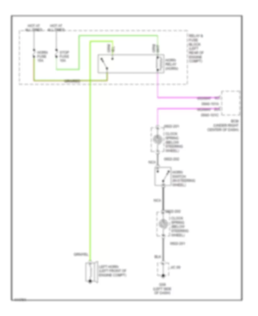
HORN
Horn Wiring Diagram for Mazda 5 Grand Touring 2014
List of elements for Horn Wiring Diagram for Mazda 5 Grand Touring 2014:
- 0922-201
- 0922-202
- 0940-101a
- 0940-101c
- Bcm (under right center of dash)
- Clock spring (below steering wheel)
- G09 (left side of dash)
- Horn fuse 15a
- Horn relay (horn)
- Horn switch (in steering wheel)
- Hot at all times
- J/c 09
- Left horn (left front of engine compt)
- Nca
- Relay & fuse block (left rear of engine compt)
- Stop fuse 10a
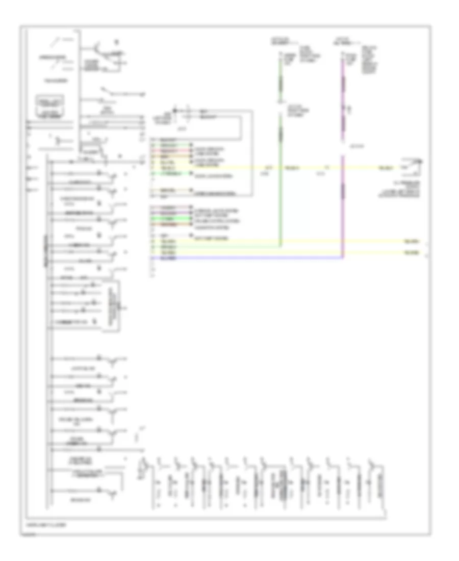
INSTRUMENT CLUSTER
Instrument Cluster Wiring Diagram (1 of 2) for Mazda 5 Grand Touring 2014
List of elements for Instrument Cluster Wiring Diagram (1 of 2) for Mazda 5 Grand Touring 2014:
- (a/t)
- A/t ind
- Abs ind
- Air bag ind
- Anti-theft system
- Brake ind
- Buzzer
- C-05
- C-13
- Charge ind
- Check engine ind
- Circuit failure detection
- Computer data lines system
- Cruise (amber) ind
- Cruise control system
- D & selector ind
- Dimmer cancel switch
- Door ind
- Door locks system
- Dsc ind
- Dsc off ind
- Ehpas ind
- Fuel cap ind
- Fuse block (right end of dash)
- G09 (left side of dash)
- Hi beam ind
- Hot at all times
- Hot in on or start
- Illum
- Ind (w/ malfunction warning light)
- Instrument cluster
- Interior lights system
- J/c 9
- J/c c-42 (right side of dash)
- J/c c-44
- Lh turn ind
- Low fuel ind
- Malfunction
- Meter fuse 10a
- Micro computer
- Navigation system
- Odo/trip fuel meter
- Oil ind
- Oil pressure switch (lower left side of automatic transaxle)
- Panel light control
- Relay & fuse block (left rear of engine compt)
- Rh turn ind
- Room fuse 15a
- Seat belts ind
- Security ind
- Selector indicator drive circuit
- Speedometer
- Tachometer
- Temp cool ind
- Temp hot ind
- Tns ind
- Tpms ind
- Trip switch
- Washer ind (if equipped)
- Wiper/washer system
Instrument Cluster Wiring Diagram (2 of 2) for Mazda 5 Grand Touring 2014
List of elements for Instrument Cluster Wiring Diagram (2 of 2) for Mazda 5 Grand Touring 2014:
- 0940-101a
- 0940-101c
- 0940-101f
- Bcm (under right center of dash)
- Brake fluid level sensor (in brake fluid reservoir)
- C-17
- C-29
- C-30
- Computer data lines system
- Fuel gauge sender unit (part of fuel pump unit)
- G02 (left front of engine compt)
- G14 (under passenger's seat)
- G17 (under driver's seat)
- J/c g02
- Left front door latch & lock actuator
- Parking brake switch (at base of parking brake lever)
- Red
- Right front door latch & lock actuator
Multi-Information System Wiring Diagram for Mazda 5 Grand Touring 2014
List of elements for Multi-Information System Wiring Diagram for Mazda 5 Grand Touring 2014:
- 0922-201
- 0922-202
- C-05
- Clock spring (below steering wheel)
- Clock switch
- Computer data lines system
- Fuse block (right end of dash)
- G11 (right end of dash)
- Hot at all times
- Hot in on or acc
- Hot in on or start
- Info
- Information display
- Interior lights system
- J/c c-42 (right side of dash)
- J/c c-44
- Meter fuse 10a
- Mirror fuse 7.5a
- Nca
- Relay & fuse block (left rear of engine compt)
- Room fuse 15a
- Steering switch (if equipped)
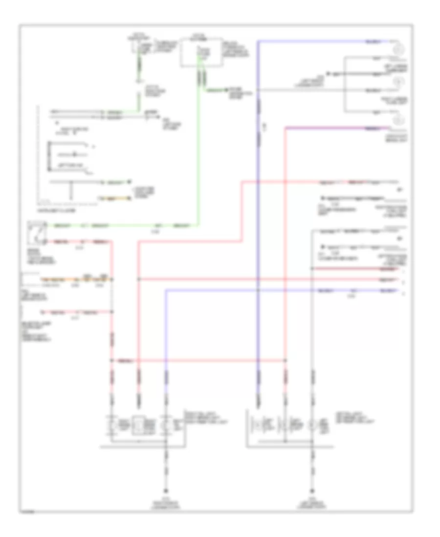
INTERIOR LIGHTS
Courtesy Lamps Wiring Diagram for Mazda 5 Grand Touring 2014
List of elements for Courtesy Lamps Wiring Diagram for Mazda 5 Grand Touring 2014:
- 0940-101a
- 0940-101b
- 0940-101e
- 0940-101f
- Bcm (under right center of dash)
- C-20
- C-22
- C-29
- C-30
- Cargo compartment light
- Computer data lines system
- Door
- Front door latch switch
- G14 (under passenger's seat)
- G16 (left side of luggage compt)
- G17 (under driver's seat)
- Hot at all times
- Interior light
- Left front door latch & lock actuator
- Left sliding door switch (left "c" pillar)
- Liftgate latch switch (part of liftgate lock actuator assembly)
- Map light
- Off
- Red
- Relay & fuse block (left rear of engine compt)
- Right front door latch & lock actuator
- Right sliding door switch (right "c" pillar)
- Room fuse 15a
Instrument Illumination Wiring Diagram for Mazda 5 Grand Touring 2014
List of elements for Instrument Illumination Wiring Diagram for Mazda 5 Grand Touring 2014:
- (if equipped)
- 0740-201a
- 0920-201a
- 0922-201
- 0922-202
- 0940-101a
- 0940-101c
- 0940-101d
- Audio unit
- Auto
- Bcm (under right center of dash)
- Buzzer
- C-05
- C-18
- C-66
- Climate control unit
- Clock spring (below steering wheel)
- Computer data lines system
- Dimmer cancel switch
- Dsc off switch
- Exterior lights system
- G09 (left side of dash)
- Hazard warning switch
- Head
- Hot at all times
- Ignition key illumination
- Illumi fuse 7.5a
- Illumi ind
- Information display
- Instrument cluster
- J/c 09
- J/c c-44
- J/c c-50 (left end of dash)
- J/c c-51
- Left seat warmer switch
- Light switch
- Microcomputer
- Nca
- Off
- Rear fan switch
- Red
- Relay & fuse block (left rear of engine compt)
- Right seat warmer switch
- Room fuse 15a
- Selector lever component (if equipped) (base of shift lever assembly)
- Steering switch
- Tns
- Tns ind
- Tns relay (tail)
NAVIGATION
Navigation Wiring Diagram (1 of 2) for Mazda 5 Grand Touring 2014
List of elements for Navigation Wiring Diagram (1 of 2) for Mazda 5 Grand Touring 2014:
- 0920-201a
- 0920-201b
- 0920-201c
- 0920-201d
- 0920-202
- 0920-214
- 4ua
- 4ub
- 4uc
- 4ud
- Antenna amp
- Audio unit
- Auxiliary jack/usb port
- C-05
- C-17
- C-18
- C-29
- C-30
- Computer data lines system
- Fuse block (right end of dash)
- G10 (right center of dash)
- Hot at all times
- Hot in on or acc
- Interior lights system
- J/c c-44
- Left front door speaker
- Left rear door speaker
- Left tweeter
- Mirror fuse 7.5a
- Nca
- Pnk
- Red
- Relay & fuse block (left rear of engine compt)
- Right front door speaker
- Right rear door speaker
- Right tweeter
- Roof antenna
- Room fuse 15a
Navigation Wiring Diagram (2 of 2) for Mazda 5 Grand Touring 2014
List of elements for Navigation Wiring Diagram (2 of 2) for Mazda 5 Grand Touring 2014:
- (right
- (right center of dash) g10
- (right side of instrument cluster) microphone
- 0922-201
- 0922-202
- Center of dash) g10
- Clock spring (below steering wheel)
- Computer data lines system
- G10 (right center of dash)
- Hang-up
- J/c c-52 (right end of dash)
- Mode
- Mute
- Nca
- Pick-up
- Pnk
- Red
- Seek+
- Seek-
- Sirius satellite radio unit (if equipped) (right end of dash)
- Steering switch
- Talk
- Vol+
- Vol-
- W/ sirius satellite radio unit
- W/o sirius satellite radio unit
Parking Assistant Wiring Diagram for Mazda 5 Grand Touring 2014
List of elements for Parking Assistant Wiring Diagram for Mazda 5 Grand Touring 2014:
- C-70
- C-71
- C-72
- Computer data lines system
- Exterior lights system
- Fuse block (right end of dash)
- G09 (left side of dash)
- G10 (right center of dash)
- Hot in on or start
- Instrument cluster
- Interior lights system
- J/c c-42 (right side of dash)
- J/c g09
- Left back sensor (behind left side of rear bumper)
- Left corner sensor (behind left end of rear bumper)
- Meter fuse 10a
- Microcomputer
- Nca
- Parking sensor control module (right end of dash)
- Parking sensor switch
- Right back sensor (behind right side of rear bumper)
- Right corner sensor (behind right end of rear bumper)
- Trailer (option) (left "c" pillar)
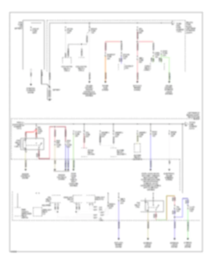
POWER DISTRIBUTION
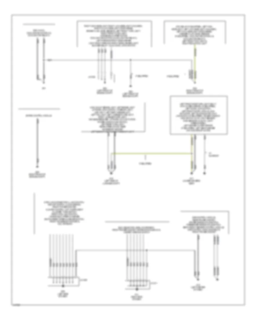
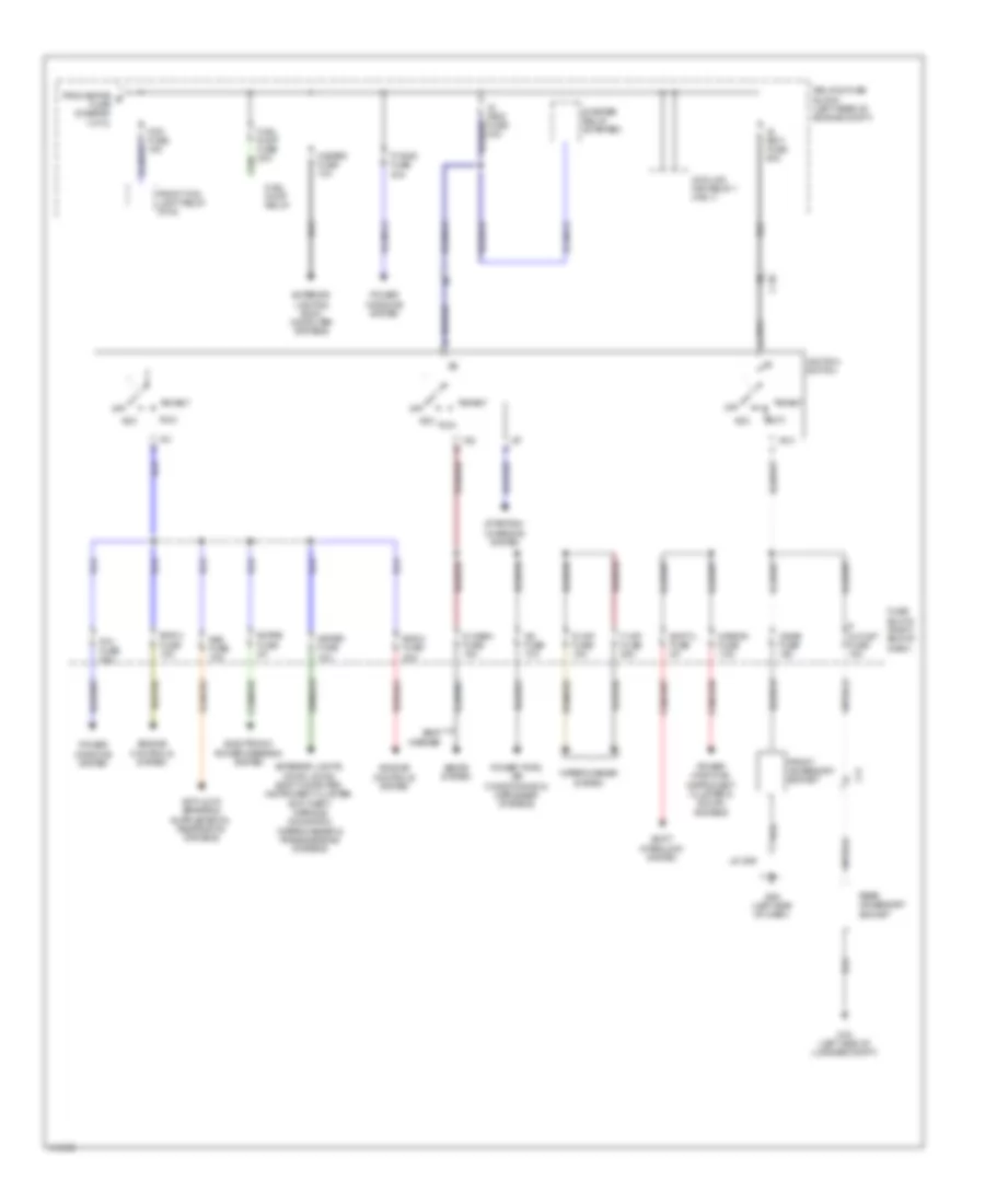
Power Distribution Wiring Diagram (1 of 2) for Mazda 5 Grand Touring 2014
List of elements for Power Distribution Wiring Diagram (1 of 2) for Mazda 5 Grand Touring 2014:
- (left rear of engine compt) relay & fuse block
- A/c mag fuse 10a
- A/c relay (a/c)
- Abs p fuse 40a
- Abs v fuse 20a
- Ad fan fuse 30a
- Anti-lock brakes system
- At main relay (at main)
- Battery
- Blower relay 1 (blower 1)
- Blower relay 2 (blower 2)
- Btn fuse 60a
- Compt)
- Cooling fan relay 2 (fan 2)
- Cooling fan relay 3 (fan 3)
- Cruise control, engine controls & transmissions systems
- Cruise control, exterior lights systems
- D lock fuse 20a
- Door locks, anti- theft & body computer systems
- Door locks, sound, anti-theft, warning, body computer, computer data lines, air conditioning, interior lights, instrument cluster & shift interlock systems
- Drl relay (dtrl) (if equipped)
- Egi main fuse 40a
- Ehpas fuse 80a
- Electronic power steering system
- Eng bar fuse 15a
- Eng inj fuse 25a
- Eng+b fuse 10a
- Engine controls system
- Exterior lights system
- From stop fuse a (diagram 1 of 2)
- Head hi fuse 20a
- Headlight relay (hi)
- Headlight relay (lo)
- Heater 1 fuse 40a
- Heater 2 fuse 30a
- Heater 3 fuse 30a
- Horn fuse 15a
- Horn relay (horn)
- Illumi fuse 7.5a
- Interior lights system
- Main fuse (on battery)
- Main relay (egi main 1)
- Main st fuse 250a
- Nca
- Power tops system
- Rear window defroster relay (defog)
- Red
- Relay & fuse block (left rear of engine
- Room fuse 15a
- Starting/ charging system
- Stop fuse 10a
- Sunroof fuse 20a
- Tail fuse 15a
- Tcm fuse 20a
- Tns relay (tail)
- To egi main fuse (diagram 1 of 2)
- To fog fuse (diagram 2 of 2)
- W/ drl
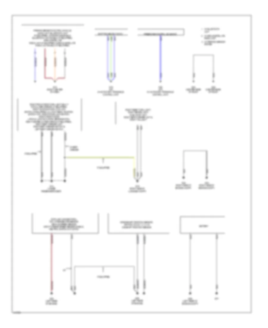
Power Distribution Wiring Diagram (2 of 2) for Mazda 5 Grand Touring 2014
List of elements for Power Distribution Wiring Diagram (2 of 2) for Mazda 5 Grand Touring 2014:
- A/c fuse 10a
- Acc
- C-05
- C17
- Cigar fuse 15a
- Cooling fan relay 1 (fan 1)
- Ehpas fuse 5a
- Electronic power steering system
- Eng 2 fuse 15a
- Eng 3 fuse 20a
- Engine controls system
- Exterior lights & body computer systems
- Exterior lights, door locks, body computer, instrument cluster, anti-theft, warning navigation wiper/washer & transmissions systems
- F wip fuse 25a
- Fog fuse 15a
- From ehpas b fuse (diagram 1 of 2)
- Front accessory socket
- Front fog light relay (fog)
- Fuel pump fuse 20a
- Fuel pump relay
- Fuse block (right end of dash)
- G09 (left side of dash)
- G16 (left side of luggage compt)
- Hazard fuse 10a
- Ig key1 fuse 50a
- Ig key2 fuse 40a
- Ig1
- Ig2
- Ignition switch
- J/c g09
- Meter fuse 10a
- Mirror fuse 7.5a
- Off
- P outlet fuse 15a
- P wind fuse 20a
- P/w fuse 30a
- Power tops, air conditioning & defogger systems
- Power windows system
- Power windows, instrument cluster & sound systems
- R wip fuse 15a
- Rear accessory socket
- Relay & fuse block (left rear of engine compt)
- Run
- S warm fuse 15a
- Sas fuse 10a
- Seat warmer
- Seats system
- Shift interlock system
- Shift/l fuse 5a
- Start
- Starter relay (starter)
- Starting/ charging system
- Wiper/washer system
POWER DOOR LOCKS
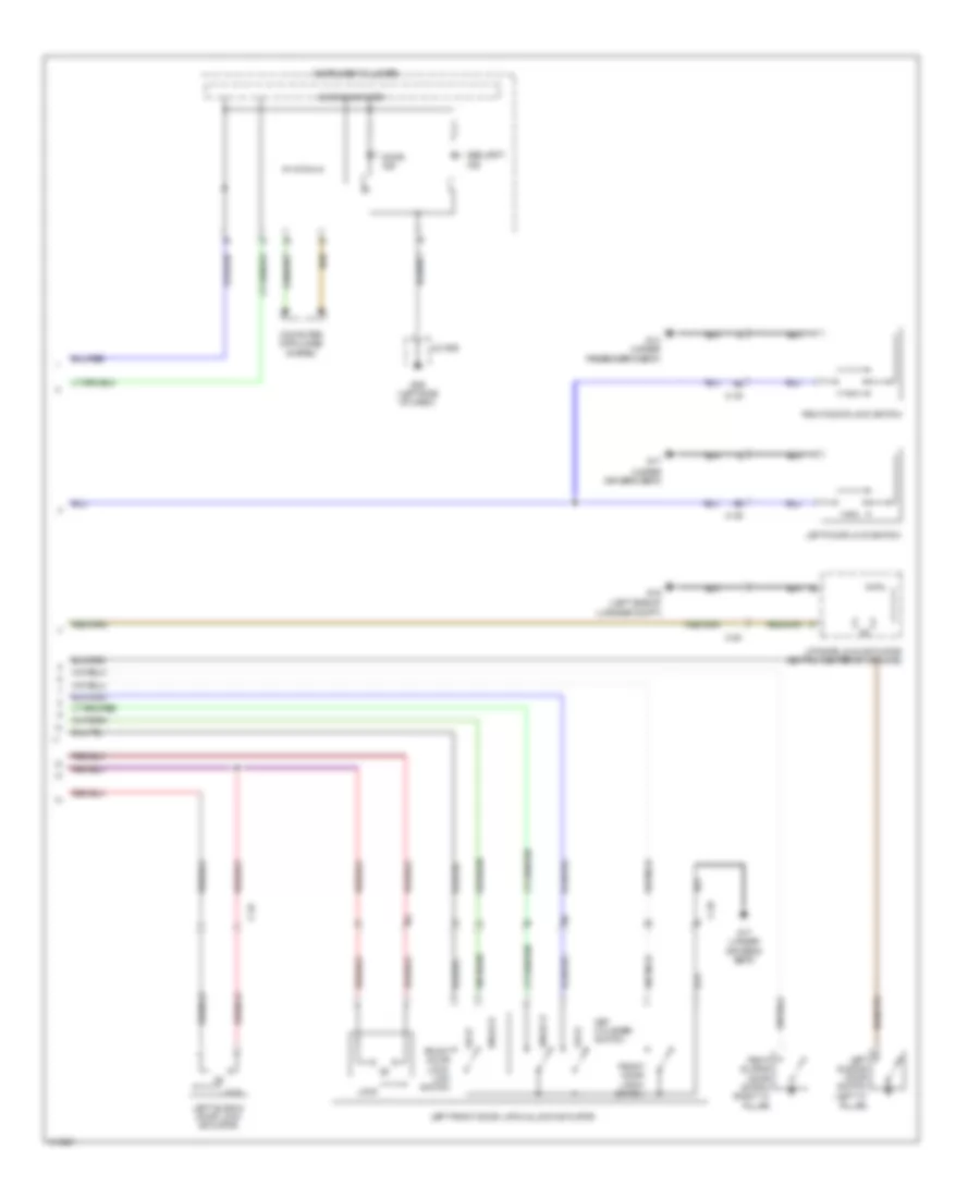
Power Door Locks Wiring Diagram (1 of 2) for Mazda 5 Grand Touring 2014
List of elements for Power Door Locks Wiring Diagram (1 of 2) for Mazda 5 Grand Touring 2014:
- (if equipped)
- (under driver's seat) g17
- (under passenger's seat) g14
- 0940-101a
- 0940-101c
- 0940-101d
- 0940-101e
- 0940-101f
- Bcm (under right center of dash)
- C-05
- C-17
- C-18
- C-20
- C-30
- C-31
- C-32
- Computer data lines system
- D lock fuse 20a
- Front door latch switch
- Front door lock- link switch
- Fuse block (right end of dash)
- G02 (left front of engine compt)
- G11 (right end of dash)
- G16 (left side of luggage compt)
- Hood latch switch (center front of engine compt)
- Hot at all times
- Hot in on or start
- J/c c-42 (right side of dash)
- J/c c-44
- J/c g02
- J/c g11
- Key reminder switch (part of ignition switch assembly)
- Keyless receiver
- Left sliding door lock-
- Liftgate opener switch
- Link switch
- Lock
- Meter fuse 10a
- Relay & fuse block (left rear of engine compt)
- Right front door latch & lock actuator
- Right sliding door lock actuator
- Right sliding door lock-
- Room fuse 15a
- Unlock
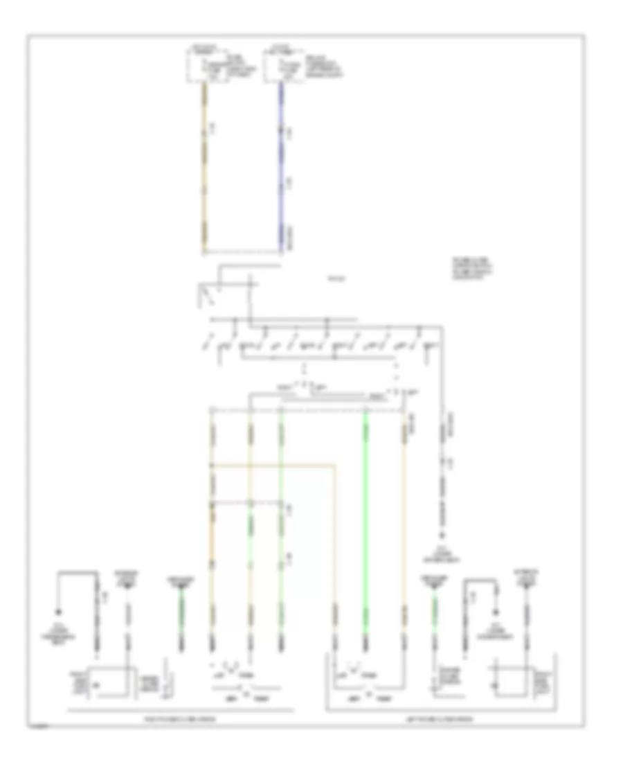
Power Door Locks Wiring Diagram (2 of 2) for Mazda 5 Grand Touring 2014
List of elements for Power Door Locks Wiring Diagram (2 of 2) for Mazda 5 Grand Touring 2014:
- (left "c" pillar)
- (under
- C-20
- C-29
- C-30
- C-32
- Computer data lines system
- Door ind
- Driver's seat)
- Front door latch switch
- Front door lock- link switch
- G09 (left side of dash)
- G14 (under passenger's seat)
- G16 (left side of
- G17
- G17 (under driver's seat)
- Instrument cluster
- J/c g09
- Key cylinder switch
- Left door lock switch
- Left front door latch & lock actuator
- Left sliding door lock actuator
- Left sliding door switch
- Liftgate lock actuator (bottom center of liftgate)
- Lock
- Luggage compt)
- Microcomputer
- Right door lock switch
- Right sliding door switch (right "c" pillar)
- Security ind
- Unlock
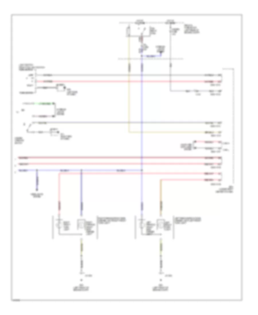
POWER MIRRORS
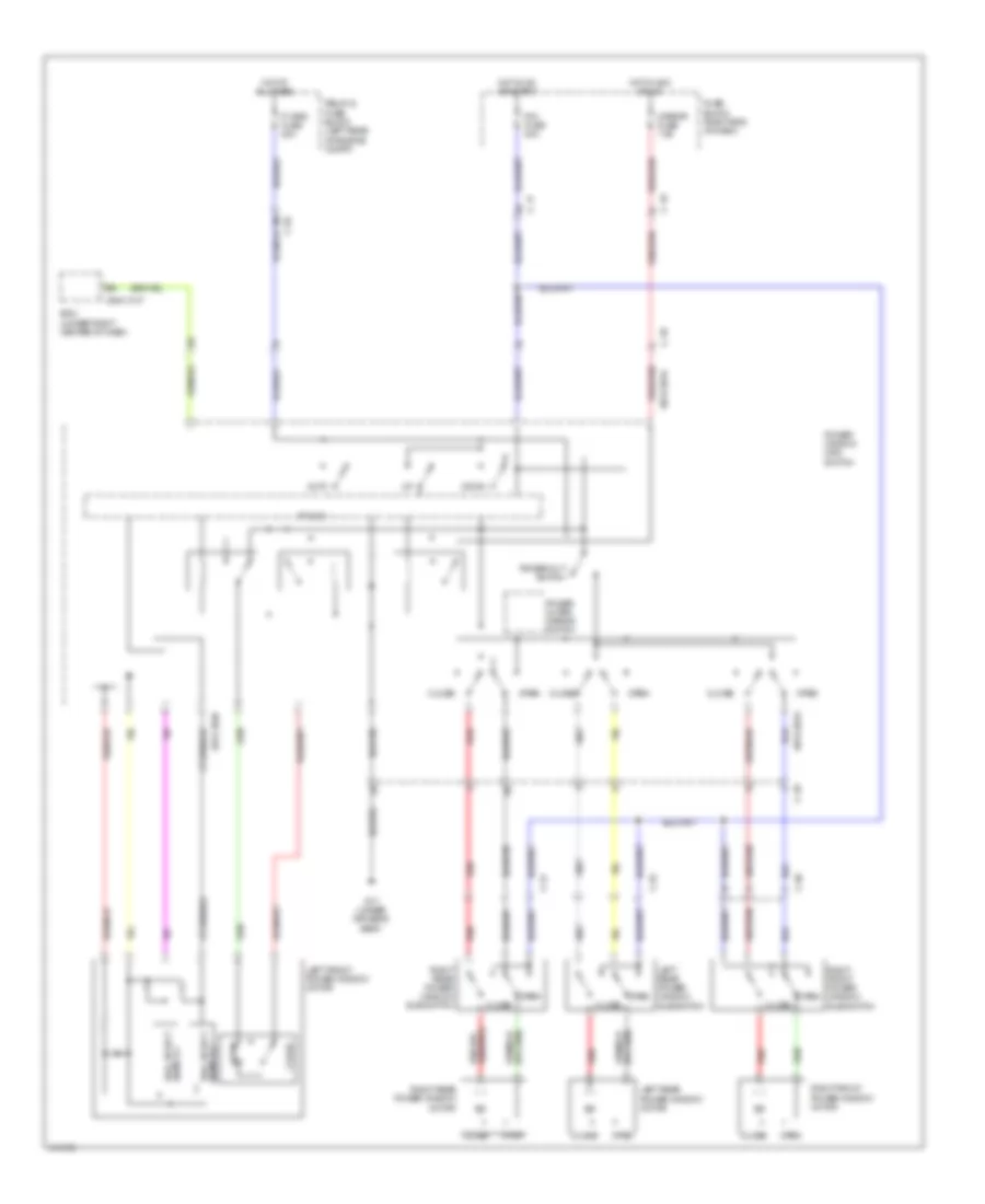
Power Mirrors Wiring Diagram for Mazda 5 Grand Touring 2014
List of elements for Power Mirrors Wiring Diagram for Mazda 5 Grand Touring 2014:
- 0912-201a
- 0912-301
- C-04
- C-18
- C-29
- C-30
- Defogger system
- Down
- Exterior lights system
- Front side turn light
- Fuse block (right end of dash)
- G14 (under passenger's seat)
- G17 (under driver's seat)
- Heated outer mirror
- Hot at all times
- Hot in on or acc
- Left
- Left power outer mirror
- Mirror fuse 7.5a
- Nca
- P wind fuse 20a
- P/w cm
- Power outer mirror switch/ power window main switch
- Relay & fuse block (left rear of engine compt)
- Right
- Right power outer mirror
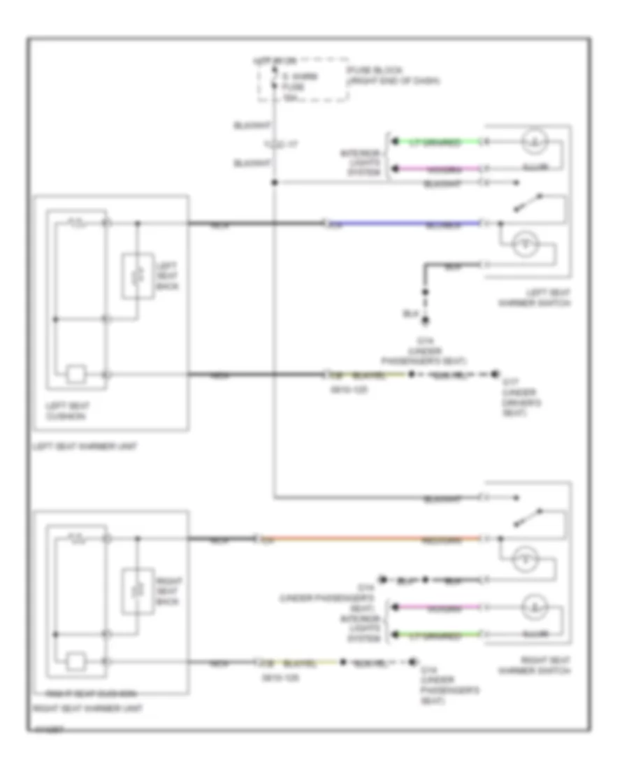
POWER SEATS
Power Seats Wiring Diagram for Mazda 5 Grand Touring 2014
List of elements for Power Seats Wiring Diagram for Mazda 5 Grand Touring 2014:
- 0810-125
- 0810-126
- C-17
- Fuse block (right end of dash)
- G14 (under passenger's seat)
- G17 (under driver's seat)
- Hot in on
- Illum
- Interior lights system
- Left seat back
- Left seat cushion
- Left seat warmer switch
- Left seat warmer unit
- Nca
- Right seat back
- Right seat cushion
- Right seat warmer switch
- Right seat warmer unit
- S. warm fuse 15a
POWER TOP/SUNROOF
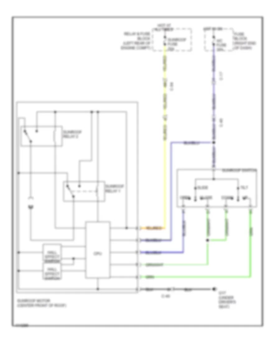
Power Top/Sunroof Wiring Diagram for Mazda 5 Grand Touring 2014
List of elements for Power Top/Sunroof Wiring Diagram for Mazda 5 Grand Touring 2014:
- A/c fuse 10a
- C-04
- C-17
- C-40
- Close
- Cpu
- Down
- Fuse block (right end of dash)
- G17 (under driver's seat)
- Hall effect switch
- Hot at all times
- Hot in on
- Open
- Relay & fuse block (left rear of engine compt)
- Slide
- Sunroof fuse 20a
- Sunroof motor (center front of roof)
- Sunroof relay 1
- Sunroof relay 2
- Sunroof switch
- Tilt
POWER WINDOWS
Power Windows Wiring Diagram for Mazda 5 Grand Touring 2014
List of elements for Power Windows Wiring Diagram for Mazda 5 Grand Touring 2014:
- 0912-201a
- 0912-201b
- 0940-101f
- Auto
- Bcm (under right center of dash)
- C-04
- C-17
- C-18
- C-29
- C-30
- C-31
- C-32
- Close
- Down
- Fuse block (right end of dash)
- G17 (under driver's seat)
- Hall effect switch 1
- Hot at all times
- Hot in acc or on
- Hot in on or start
- Left front power window motor
- Left rear power window motor
- Left rear power window sub switch
- Mirror fuse 7.5a
- Open
- Open m
- P wind fuse 20a
- P/w cm
- P/w fuse 30a
- Power outer mirror switch
- Power window main switch
- Power-cut switch
- Red
- Relay & fuse block (left rear of engine compt)
- Right front power window motor
- Right front power window sub switch
- Right rear power window motor
- Right rear power window sub switch
- Switch 2 hall effect
RADIO
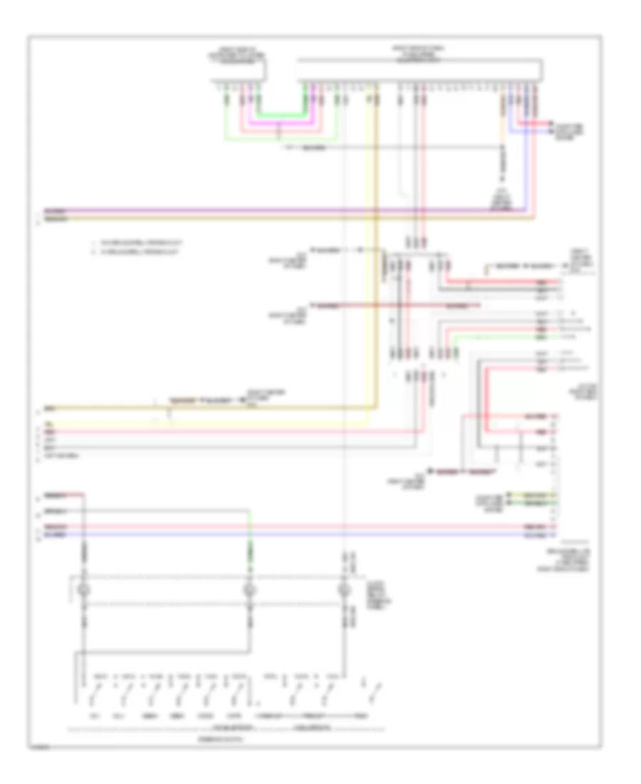
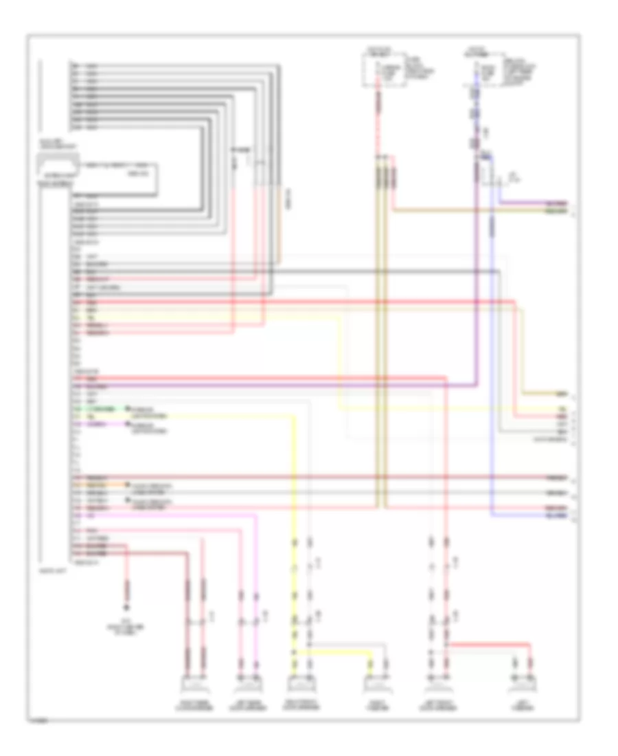
Radio Wiring Diagram (1 of 2) for Mazda 5 Grand Touring 2014
List of elements for Radio Wiring Diagram (1 of 2) for Mazda 5 Grand Touring 2014:
- 0920-201a
- 0920-201b
- 0920-201c
- 0920-201d
- 0920-202
- 0920-214
- 4ua
- 4ub
- 4uc
- 4ud
- Antenna amp
- Audio unit
- Auxiliary jack/usb port
- C-05
- C-17
- C-18
- C-29
- C-30
- Computer data lines system
- Fuse block (right end of dash)
- G10 (right center of dash)
- Hot at all times
- Hot in on or acc
- Interior lights system
- J/c c-44
- Left front door speaker
- Left rear door speaker
- Left tweeter
- Mirror fuse 7.5a
- Nca
- Pnk
- Red
- Relay & fuse block (left rear of engine compt)
- Right front door speaker
- Right rear door speaker
- Right tweeter
- Roof antenna
- Room fuse 15a
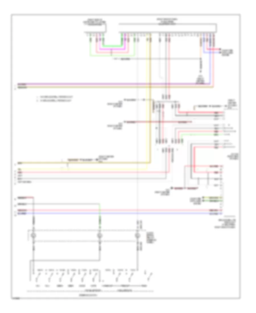
Radio Wiring Diagram (2 of 2) for Mazda 5 Grand Touring 2014
List of elements for Radio Wiring Diagram (2 of 2) for Mazda 5 Grand Touring 2014:
- (right
- (right center of dash) g10
- (right side of instrument cluster) microphone
- 0922-201
- 0922-202
- Center of dash) g10
- Clock spring (below steering wheel)
- Computer data lines system
- G10 (right center of dash)
- Hang-up
- J/c c-52 (right end of dash)
- Mode
- Mute
- Nca
- Pick-up
- Pnk
- Red
- Seek+
- Seek-
- Sirius satellite radio unit (if equipped) (right end of dash)
- Steering switch
- Talk
- Vol+
- Vol-
- W/ sirius satellite radio unit
- W/o sirius satellite radio unit
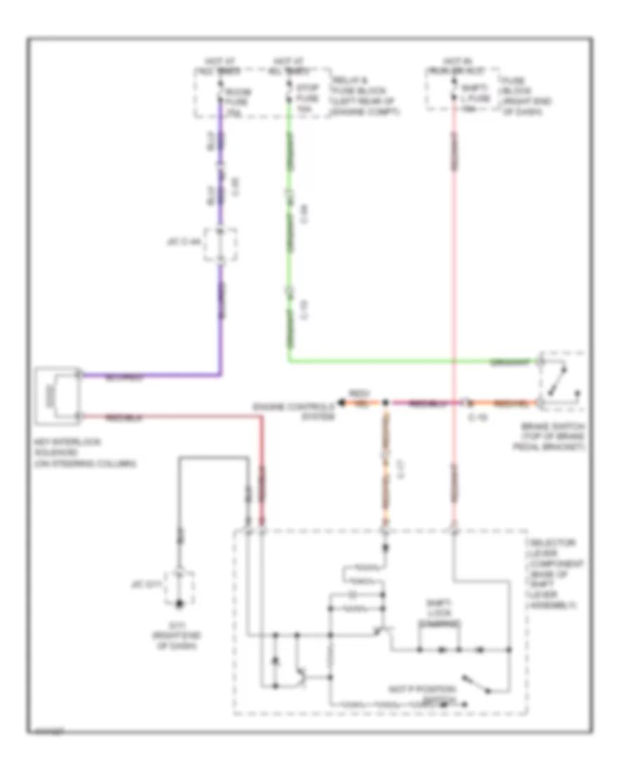
SHIFT INTERLOCK
Shift Interlock Wiring Diagram for Mazda 5 Grand Touring 2014
List of elements for Shift Interlock Wiring Diagram for Mazda 5 Grand Touring 2014:
- (on steering column)
- Brake switch (top of brake pedal bracket)
- C-04
- C-05
- C-10
- C-17
- Engine controls system
- Fuse block (right end of dash)
- G11 (right end of dash)
- Hot at all times
- Hot in run or acc
- J/c c-44
- J/c g11
- Key interlock solenoid
- Not p position switch
- Relay & fuse block (left rear of engine compt)
- Room fuse 15a
- Selector lever component (base of shift lever assembly)
- Shift- lock solenoid
- Shift/ l fuse 15a
- Stop fuse 10a
STARTING/CHARGING
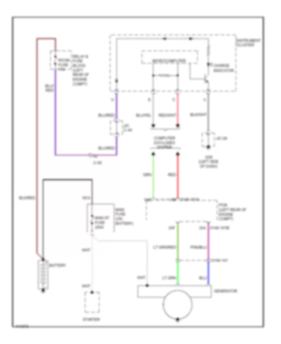
Charging Wiring Diagram for Mazda 5 Grand Touring 2014
List of elements for Charging Wiring Diagram for Mazda 5 Grand Touring 2014:
- 0140-101a
- 0140-141
- 1ai
- 1am
- 2aa 0140-101b
- 2af
- Battery
- C-05
- Charge
- Computer data lines system
- G09 (left side of dash)
- Generator
- Indicator
- Instrument cluster
- J/c 09
- J/c c-44
- Main fuse (on battery)
- Main st fuse 250a
- Microcomputer
- Nca
- Pcm (left rear of engine compt)
- Red
- Relay & fuse block (left rear of engine compt)
- Room fuse 15a
- Starter
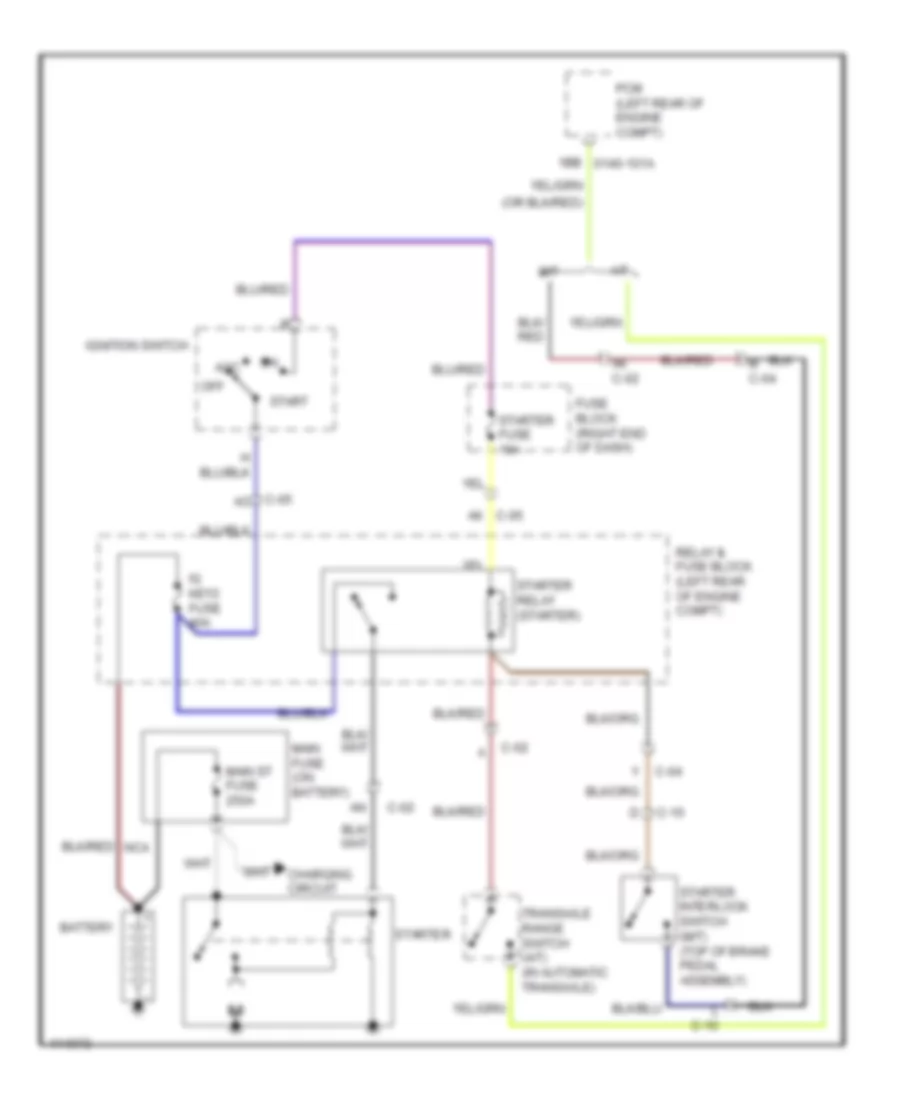
Starting Wiring Diagram for Mazda 5 Grand Touring 2014
List of elements for Starting Wiring Diagram for Mazda 5 Grand Touring 2014:
- 1bb 0140-101a
- A/t
- Acc
- Ak c-02
- Ak c-05
- Battery
- C-02
- C-04
- C-05 ao
- C-10
- Charging circuit
- Fuse block (right end of dash)
- Ig key2 fuse 40a
- Ignition switch
- L c-10
- M c-04
- M/t
- Main fuse (on battery)
- Main st fuse 250a
- Off
- Pcm (left rear of engine compt)
- Relay & fuse block (left rear of engine compt)
- Start
- Starter
- Starter fuse 10a
- Starter interlock switch (m/t) (top of brake pedal assembly)
- Starter relay (starter)
- Transaxle range switch (a/t) (in automatic transaxle)
SUPPLEMENTAL RESTRAINTS
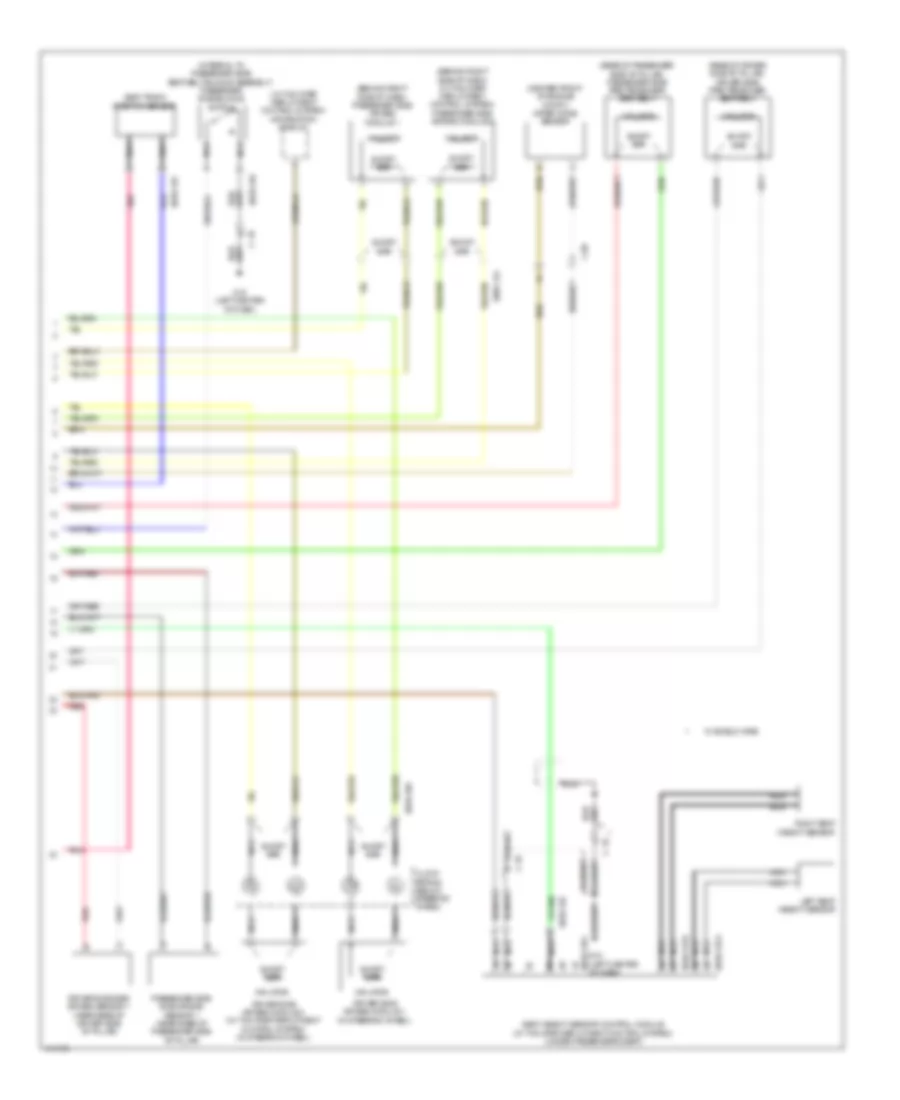
Supplemental Restraints Wiring Diagram (1 of 2) for Mazda 5 Grand Touring 2014
List of elements for Supplemental Restraints Wiring Diagram (1 of 2) for Mazda 5 Grand Touring 2014:
- (integral to driver side seat belt buckle assembly) driver side buckle switch
- (left center of dash)
- (left side of dash)
- 0810-101a
- 0810-101b
- 0810-125
- 0810-126
- 2aa
- 2ab
- 2ac
- 2ad
- 2ae
- 2af
- 2ag
- 2ah
- 2ai
- 2aj
- 2ak
- 2al
- 2am
- 2an
- Air bag ind
- C-17
- C-18
- Circuit failure detection
- Computer data lines system
- Driver side curtain air bag module (in driver side "d" pillar)
- Driver-side side air bag module (outer edge of driver side seat back)
- Driver-side side air bag sensor 2 (near base of driver side "c" pillar)
- Fuse block (right end of dash)
- G09
- G12
- G12 (left center of dash)
- Hot in on or start
- Inflator
- Instrument cluster
- Joint conn- ector c-43 (right end of dash)
- Joint connector c-42 (right side of dash)
- Meter fuse 10a
- Micro computer
- Nca
- Passenger side air bag sensor 2 (near base of passenger side "c" pillar)
- Passenger side curtain air bag module (in passenger side "d" pillar)
- Passenger-side side air bag module (outer edge of passenger side seat back)
- Pnk
- Red
- Sas control module (under center console)
- Sas fuse 10a
- Seat belt ind
- Short bar
Supplemental Restraints Wiring Diagram (2 of 2) for Mazda 5 Grand Touring 2014
List of elements for Supplemental Restraints Wiring Diagram (2 of 2) for Mazda 5 Grand Touring 2014:
- (base of driver side "b" pillar) driver side pre-tensioner seat belt
- (base of passenger side "b" pillar) passenger side pre-tensioner seat belt
- (behind right side of dash) (w/ two step deployment control system) passenger side air bag module 2
- (behind right side of dash) passenger side air bag module 1
- (center front of engine compt) crash zone sensor
- (integral to passenger side seat belt buckle assembly) passenger side buckle switch
- (left center of dash)
- (w/ two step deployment control system) information display
- 0810-105
- 0810-124
- 0810-125
- 0810-126
- 0810-137a
- 0810-137b
- 0810-137c
- C-05
- C-18
- Clock spring (below steering wheel)
- Driver side air bag module 1 (in steering wheel)
- Driver side air bag module 2 (w/ two step deployment control system) (in steering wheel)
- Driver side side air bag sensor 1 (near base of driver side "b" pillar)
- G12
- G12 (left center of dash)
- Inflator
- Left seat weight sensor
- Nca
- Passenger side side air bag sensor 1 (near base of passenger side "b" pillar)
- Pnk
- Red
- Right seat weight sensor
- Seat track position sensor
- Seat weight sensor control module (w/ two step deployment control system) (under passenger's seat)
- Short bar
- W/ shield wire
TRANSMISSION
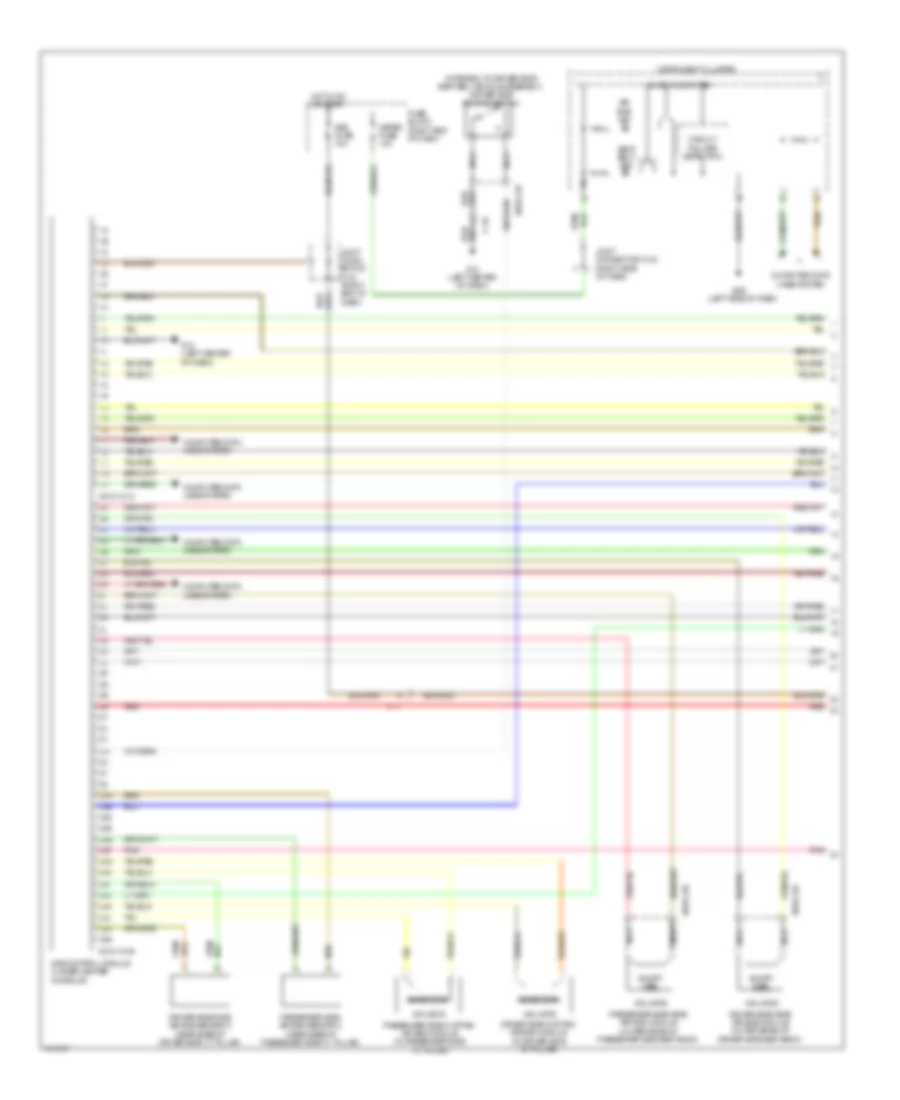
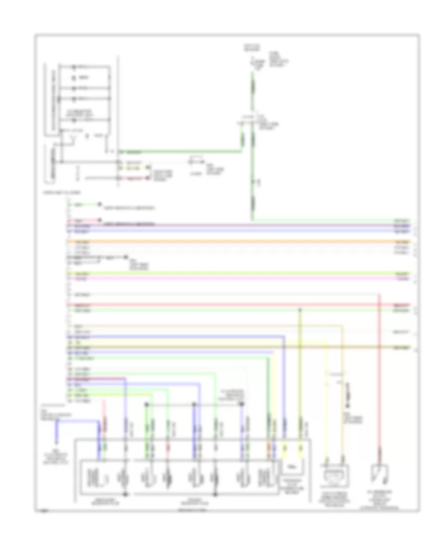
Transmission Wiring Diagram (1 of 2) for Mazda 5 Grand Touring 2014
List of elements for Transmission Wiring Diagram (1 of 2) for Mazda 5 Grand Touring 2014:
- (a/t)
- (in automatic transaxle control unit) g19
- 0517-105
- 0517-107
- A/t ind
- C-05
- Computer data lines system
- D & selector indicator light
- Fuse block (right end of dash)
- G09 (left side of dash)
- G20 (in automatic transaxle control unit)
- G23 (left rear of engine)
- Hot in on or start
- Input/turbine speed sensor (top of automatic transaxle)
- Instrument cluster
- J/c c-42 (right side of dash)
- J/c g09
- Meter fuse 10a
- Micro computer
- Oil pressure switch (lower left side of automatic transaxle)
- Pressure control solenoid b
- Primary solenoid valve
- Red
- Secondary solenoid valve
- Selector indicator drive circuit
- Solenoid a control pressure
- Solenoid a shift
- Solenoid b shift
- Solenoid c shift
- Solenoid d shift
- Solenoid e shift
- Solenoid f shift
- Tcm (top of automatic transaxle)
- Transaxle case
- Transaxle fluid temperature sensor
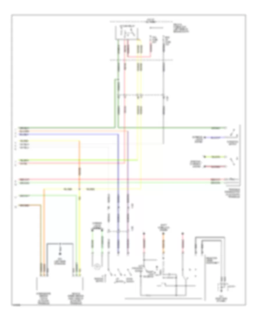
Transmission Wiring Diagram (2 of 2) for Mazda 5 Grand Touring 2014
List of elements for Transmission Wiring Diagram (2 of 2) for Mazda 5 Grand Touring 2014:
- A/t main relay
- C-02
- C-05
- Down switch
- Exterior lights system
- G11 (right end of dash)
- G23 (left rear of engine)
- Hot at all times
- Interior lights system
- Intermediate sensor (top of automatic transaxle)
- J/c g11
- M position switch
- Not p position switch
- R position switch
- Relay & fuse block (left rear of engine compt)
- Selector lever component
- Shift interlock system
- Shift lock solenoid
- Starting/ charging system
- Tcm fuse 20a
- Transaxle range switch (in automatic transaxle)
- Up switch
- Vehicle speed sensor (right side of automatic transaxle)
TRUNK, TAILGATE, FUEL DOOR
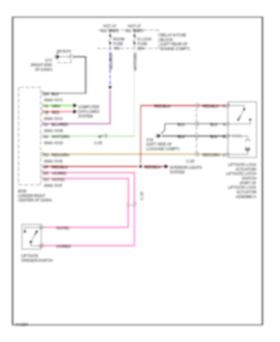
Trunk/Tailgate Release Wiring Diagram for Mazda 5 Grand Touring 2014
List of elements for Trunk/Tailgate Release Wiring Diagram for Mazda 5 Grand Touring 2014:
- 0940-101a
- 0940-101b
- 0940-101c
- 0940-101d
- 0940-101e
- 0940-101f
- Bcm (under right center of dash)
- C-05
- C-20
- Computer data lines system
- D lock fuse 20a
- G11 (right end of dash)
- G16 (left side of luggage compt)
- Hot at all times
- Interior lights system
- J/c g11
- Liftgate lock actuator/ liftgate latch switch (part of liftgate lock actuator assembly)
- Liftgate opener switch
- Red
- Relay & fuse block (left rear of engine compt)
- Room fuse 15a
WARNING SYSTEMS
Warning Systems Wiring Diagram for Mazda 5 Grand Touring 2014
List of elements for Warning Systems Wiring Diagram for Mazda 5 Grand Touring 2014:
- (at base of parking brake lever)
- 0810-101a
- 0810-101b
- 0810-125
- 0810-126
- 0940-101a
- 0940-101c
- 0940-101f
- Bcm (under right center of dash)
- Brake fluid level sensor (in brake fluid reservoir)
- Brake ind
- Buzzer
- C-05
- C-17
- C-18
- C-29
- C-30
- Computer data lines system
- Door ind
- Driver side buckle switch (integral to driver seat belt buckle assembly)
- Fuse block (right end of dash)
- G02 (left front of engine compt)
- G09 (left side of dash)
- G12 (left center of dash)
- G14 (under passenger's seat)
- G17 (under driver's seat)
- Hot at all times
- Hot in on or start
- Instrument cluster
- J/c c-42 (right side of dash)
- J/c c-44
- J/c-02
- J/c-09
- Key reminder switch
- Left front door latch & lock actuator
- Meter fuse 10a
- Microcomputer
- Nca
- Parking brake switch
- Passenger side buckle switch (integral to passenger seat belt buckle assembly)
- Relay & fuse block (left rear of engine compt)
- Right front door latch & lock actuator
- Room fuse 15a
- Sas control module (under center console)
- Seat belt ind
- Tpms ind
- Trip switch
WIPER/WASHER
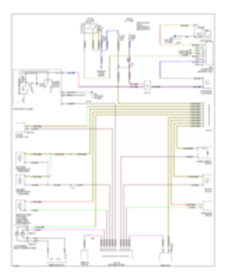
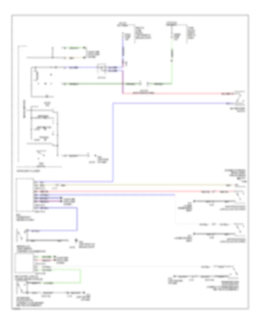
Front Wiper/Washer Wiring Diagram, with Auto Wiper System for Mazda 5 Grand Touring 2014
List of elements for Front Wiper/Washer Wiring Diagram, with Auto Wiper System for Mazda 5 Grand Touring 2014:
- 0940-101a
- 0940-101b
- 0940-101d
- 0940-101e
- Auto
- Auto light sensor/ rain sensor (if equipped) (top center of windshield)
- Bcm (under right center of dash)
- C-05
- C-17
- C-40
- Circuit breaker
- Computer data lines system
- F wip fuse 25a
- Fuse block (right end of dash)
- G02 (left front of engine compt)
- G04 (right front of engine compt)
- G09 (left side of dash)
- G11 (right end of dash)
- G17 (under driver's seat)
- Hot in on
- Hot in on or start
- Instrument cluster
- J/c c-42 (right side of dash)
- J/c g02
- J/c g09
- J/c g11
- Meter fuse 10a
- Microcomputer
- Mist
- Nca
- Off
- Red
- Washer fluid level sensor (if equipped) (in washer fluid reservoir)
- Washer ind
- Washer motor (on washer fluid reservoir)
- Windshield washer switch
- Windshield wiper & washer switch/ rear wiper & washer switch
- Windshield wiper motor (left rear of engine compt)
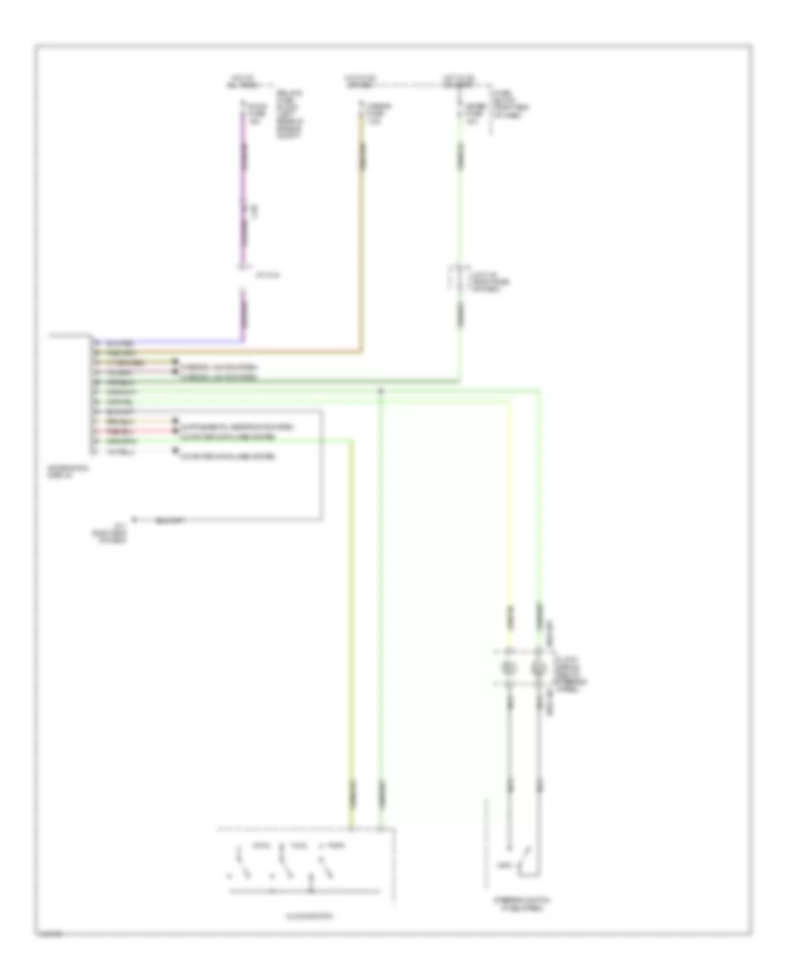
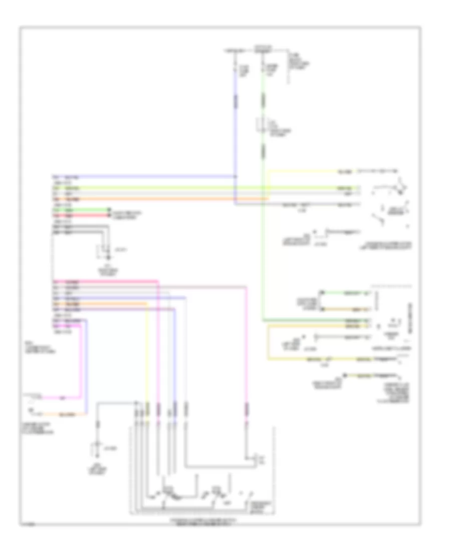
Front Wiper/Washer Wiring Diagram, without Auto Wiper System for Mazda 5 Grand Touring 2014
List of elements for Front Wiper/Washer Wiring Diagram, without Auto Wiper System for Mazda 5 Grand Touring 2014:
- 0940-101a
- 0940-101b
- 0940-101d
- Bcm (under right center of dash)
- C-05
- Circuit breaker
- Computer data lines system
- F wip fuse 25a
- Fuse block (right end of dash)
- G02 (left front of engine compt)
- G04 (right front of engine compt)
- G09 (left side of dash)
- G11 (right end of dash)
- Hot in on
- Hot in on or start
- Instrument cluster
- Int & auto
- Int vol
- J/c c-42 (right side of dash)
- J/c g02
- J/c g09
- J/c g11
- Meter fuse 10a
- Microcomputer
- Mist
- Nca
- Off
- Red
- Washer fluid level sensor (if equipped) (in washer fluid reservoir)
- Washer ind
- Washer motor (on washer fluid reservoir)
- Windshield washer switch
- Windshield wiper & washer switch/ rear wiper & washer switch
- Windshield wiper motor (left rear of engine compt)
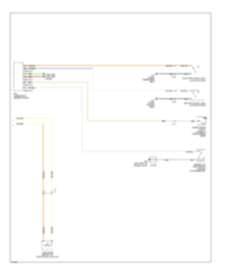
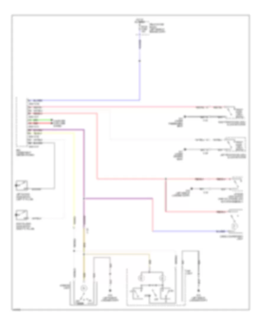
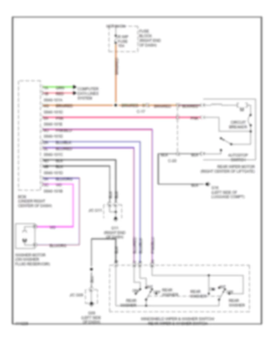
Rear Wiper/Washer Wiring Diagram for Mazda 5 Grand Touring 2014
List of elements for Rear Wiper/Washer Wiring Diagram for Mazda 5 Grand Touring 2014:
- 0940-101a
- 0940-101b
- 0940-101c
- 0940-101d
- 0940-101e
- Autostop switch
- Bcm (under right center of dash)
- C-17
- C-20
- Circuit breaker
- Computer data lines system
- Fuse block (right end of dash)
- G09 (left side of dash)
- G11 (right end of dash)
- G16 (left side of luggage compt)
- Hot in on
- Int
- J/c g09
- J/c g11
- Off
- Pnk
- R wip fuse 15a
- Rear washer
- Rear wiper motor (right center of liftgate)
- Red
- Washer motor (on washer fluid reservoir)
- Windshield wiper & washer switch/ rear wiper & washer switch