AIR CONDITIONING
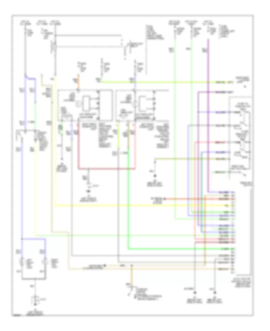
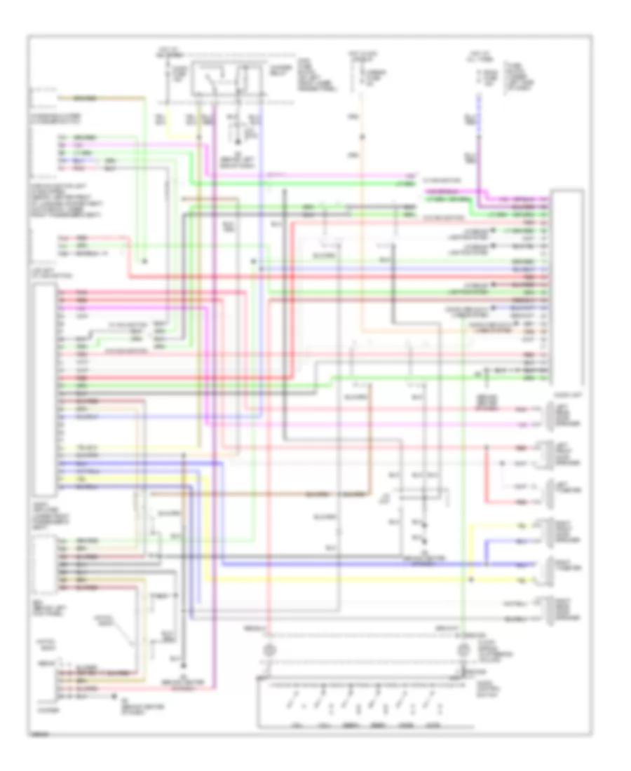
2.3L
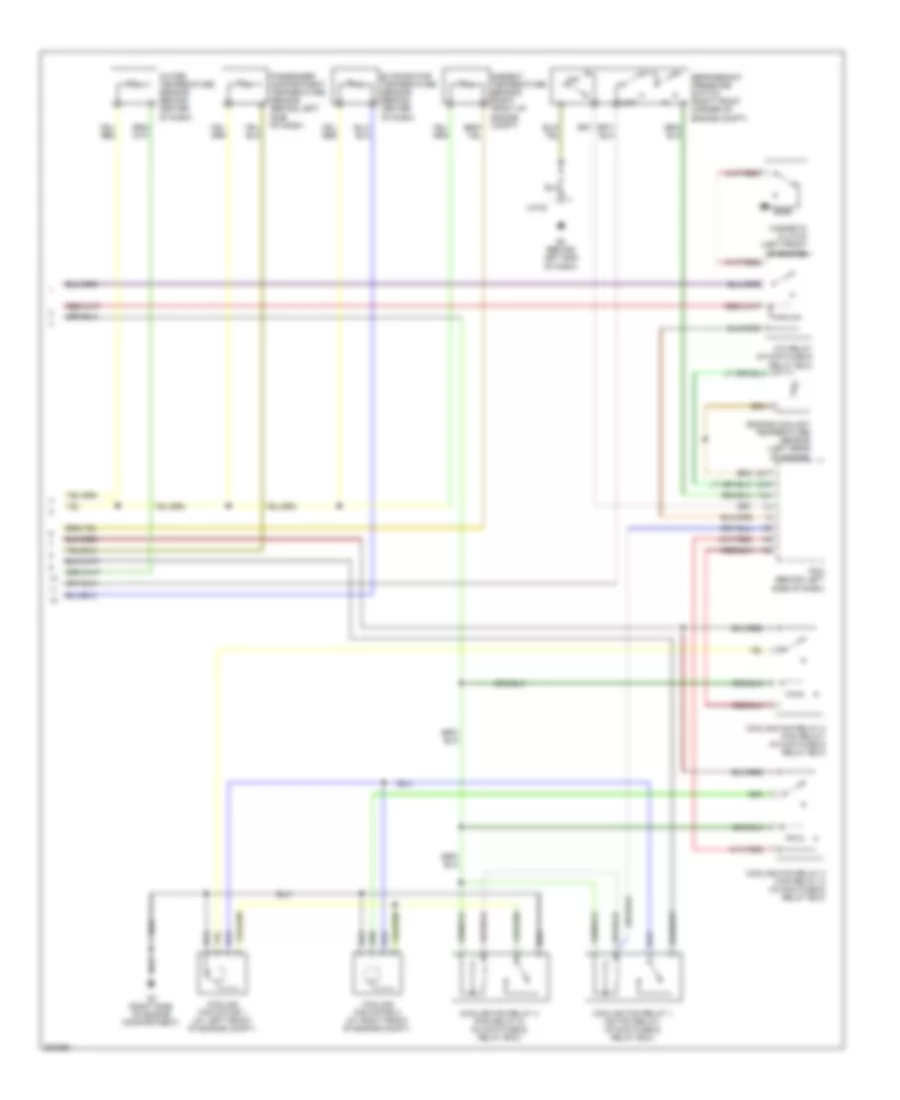
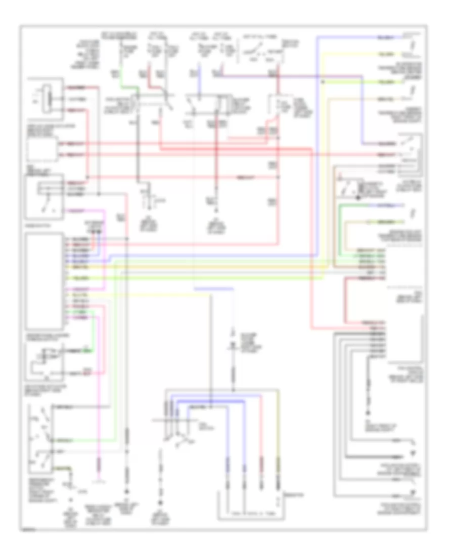
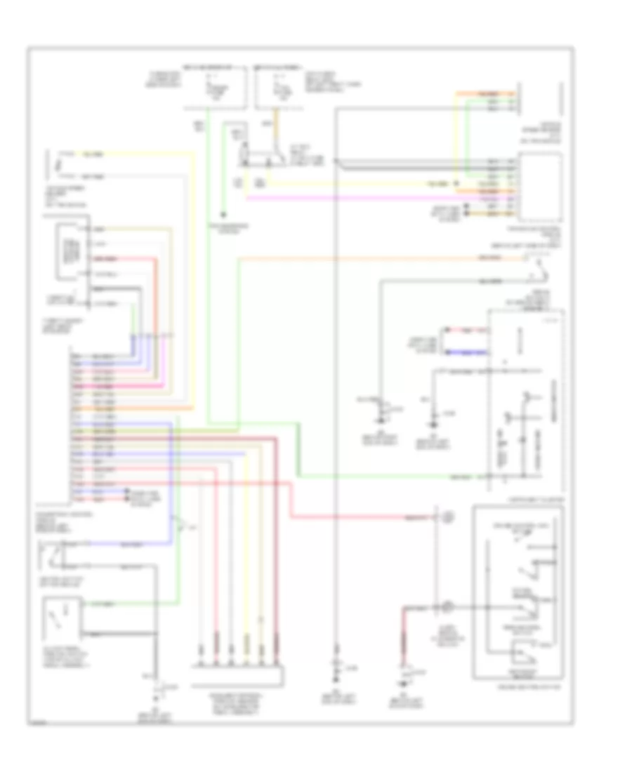
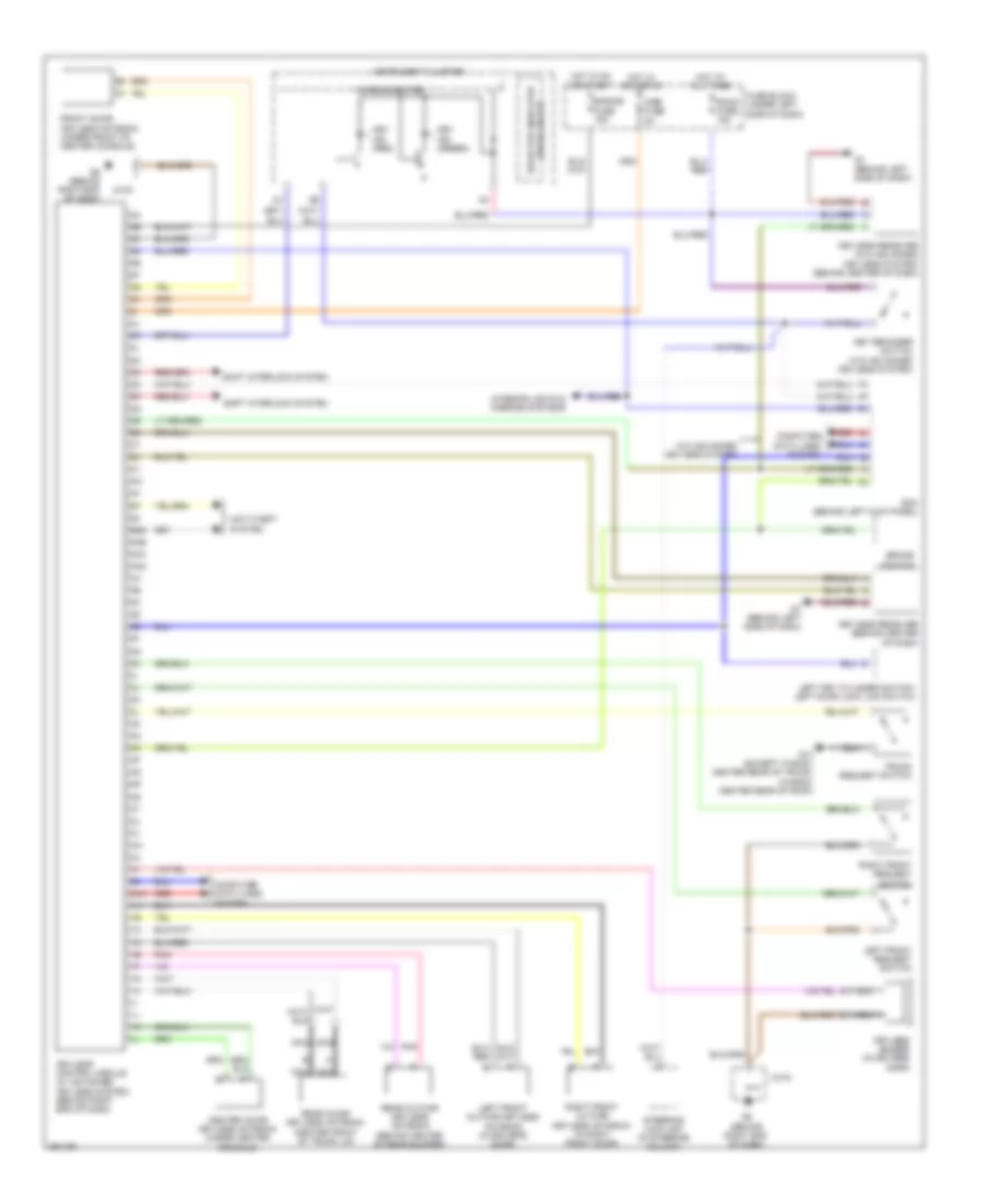
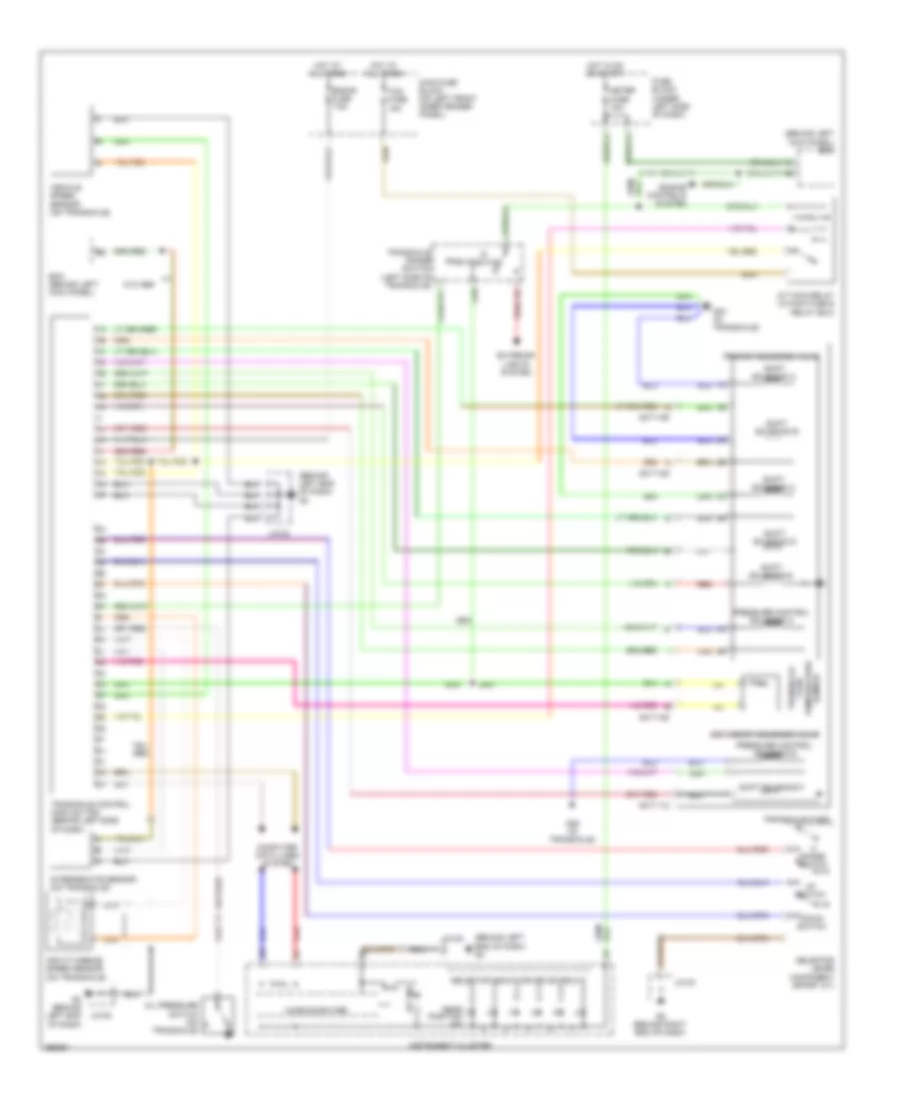
2.3L, Automatic A/C Wiring Diagram (1 of 2) for Mazda 6 i Grand Touring 2008

List of elements for 2.3L, Automatic A/C Wiring Diagram (1 of 2) for Mazda 6 i Grand Touring 2008:
- (in main fuse & relay box) rear window defroster relay
- (on fuse block) blower relay
- A/c fuse 10a
- Ad fan fuse 30a
- Air intake actuator (behind right side of dash)
- Air mix actuator (behind right side of dash)
- Airflow mode actuator (behind right side of dash)
- Bcm (behind left kick panel)
- Blower fuse 40a
- Blower motor (under right side of dash)
- Check connector (under right side of dash)
- Climate control unit/ hazard warning switch
- Exterior lights system
- Fan fuse 30a
- Fuse block (under left side of dash)
- G1 (left side of engine compt)
- G7 (behind left side of dash)
- Hot at all times
- Hot in on
- Hot in on or start
- Interior lights system
- Jc-01
- Mag fuse 10a
- Main fuse block (main fuse & relay box) (on left front inner fender panel)
- Meter fuse 15a
- Nca
- Pwm unit (behind right side of dash)
- Room fuse 15a
- Solar radiation sensor (top left side of dash)
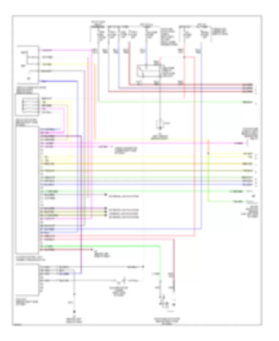
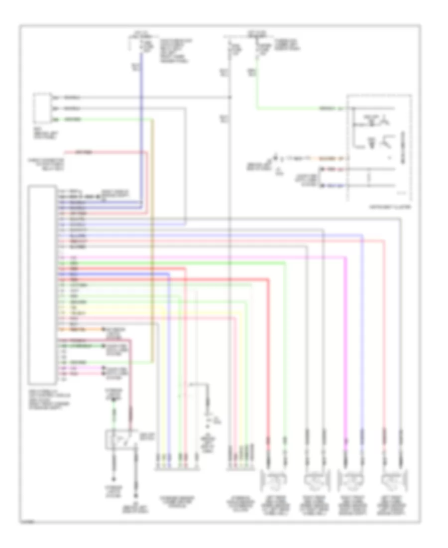
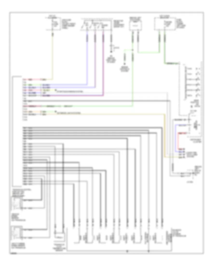
2.3L, Automatic A/C Wiring Diagram (2 of 2) for Mazda 6 i Grand Touring 2008
List of elements for 2.3L, Automatic A/C Wiring Diagram (2 of 2) for Mazda 6 i Grand Touring 2008:
- 1au
- 2ah
- 2ay
- A/c relay (in main fuse & relay box)
- Ambient temperature sensor (right front of engine compt)
- Cooling fan motor 1 (at left front of engine compt)
- Cooling fan motor 2 (at right front of engine compt)
- Cooling fan relay 1 (ad fan relay) (in main fuse & relay box)
- Cooling fan relay 2 (fan relay) (in main fuse & relay box)
- Cooling fan relay 3 (fan relay 3) (in main fuse & relay box)
- Cooling fan relay 4 (fan relay 2) (in main fuse & relay box)
- Engine coolant temperature sensor (left rear of engine)
- Evaporator temperature sensor (behind center of dash)
- G2 (behind left end of dash)
- G3 (right side of engine compartment)
- J/c-02
- Low
- Magnetic clutch (left front of engine)
- Mid
- Passenger compartment temperature sensor (behind left side of dash)
- Pcm (behind left side of dash)
- Refrigerant pressure switch (right front corner of engine compt)
- Water temperature sensor (behind center of dash)
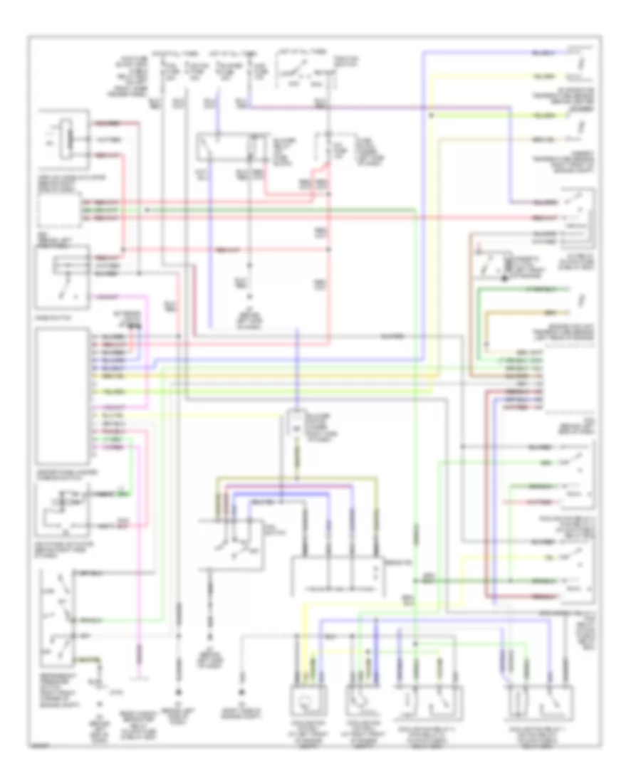
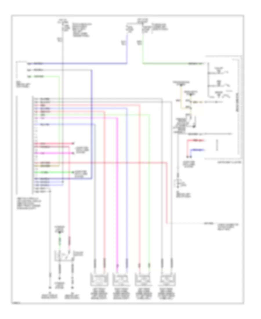
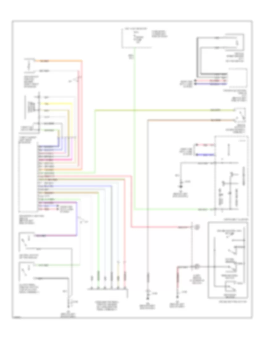
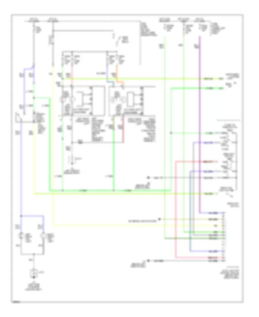
2.3L, Manual A/C Wiring Diagram for Mazda 6 i Grand Touring 2008
List of elements for 2.3L, Manual A/C Wiring Diagram for Mazda 6 i Grand Touring 2008:
- (behind left end of dash)
- (behind left side of dash)
- 1au
- 2ah
- 2ay
- A/c fuse 10a
- A/c relay (in main fuse & relay box)
- Acc
- Ad fan fuse 30a
- Air intake actuator (behind right side of dash)
- Airflow mode actuator (behind right side of dash)
- Ambient temperature sensor (right front of engine compt)
- Bcm (behind left kick panel)
- Blower fuse 40a
- Blower motor (under right side of dash)
- Blower relay (on fuse block)
- Center panel/hazard warning switch
- Cooling fan motor 1 (at left front of engine compt)
- Cooling fan motor 2 (at right front of engine compt)
- Cooling fan relay 1 (ad fan relay) (in main fuse & relay box)
- Cooling fan relay 2 (fan relay) (in main fuse & relay box)
- Cooling fan relay 3 (fan relay 3) (in main fuse & relay box)
- Cooling fan relay 4 (fan relay 2) (in main fuse & relay box)
- Driver
- Engine coolant temperature sensor (left rear of engine)
- Evaporator temperature sensor (behind center of dash)
- Exterior lights system
- Fan fuse 30a
- Fan switch
- Fuse block (under left side of dash)
- G3 (right side of engine compt)
- G7 (behind left side of dash)
- Hot at all times
- Ignition switch
- Jc-02
- Lock
- Low
- Mag fuse 10a
- Magnetic clutch (left front of engine)
- Main fuse block (main fuse & relay box) (on left front inner fender panel)
- Mid
- Mode switch
- Nca
- Off
- Pcm (behind left side of dash)
- Rear window defroster relay (in main fuse & relay box)
- Refrigerant pressure switch (right front corner of engine compt)
- Resistor
- Run
- Start
3.0L
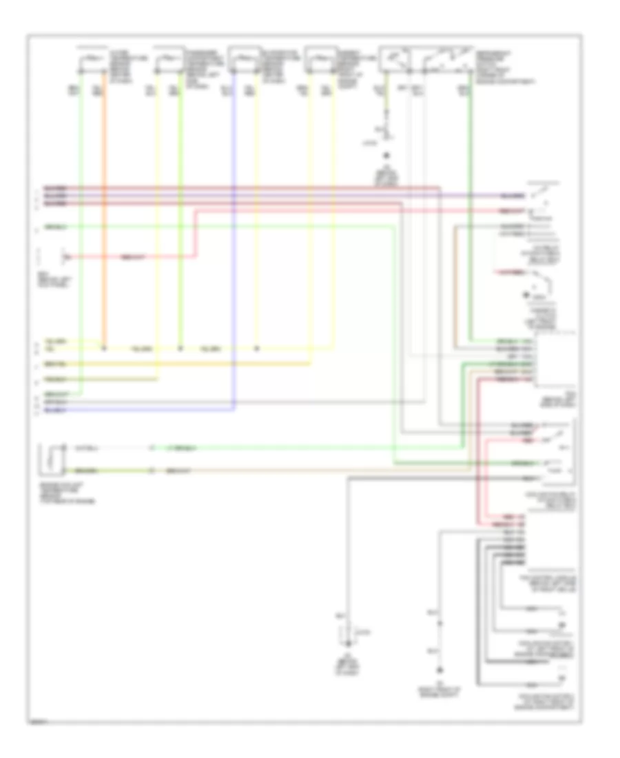
3.0L, Automatic A/C Wiring Diagram (1 of 2) for Mazda 6 i Grand Touring 2008
List of elements for 3.0L, Automatic A/C Wiring Diagram (1 of 2) for Mazda 6 i Grand Touring 2008:
- (in main fuse & relay box) rear window defroster relay
- A/c fuse 10a
- Air intake actuator (behind right side of dash)
- Air mix actuator (behind right side of dash)
- Airflow mode actuator (behind right side of dash)
- Blower fuse 40a
- Blower motor (under right side of dash)
- Blower relay (on fuse block)
- Check connector (under right side of dash)
- Climate control unit/ hazard warning switch
- Def
- Eng bb fuse 5a
- Exterior lights system
- Fan 1 fuse 30a
- Fan 2 fuse 30a
- Fuse block (under left side of dash)
- G1 (left side of engine compt)
- G7 (behind left side of dash)
- Hot at all times
- Hot in on
- Hot w/ main relay energized
- Interior lights system
- Jc-01
- Mag fuse 10a
- Main fuse block (main fuse & relay box) (on left front inner fender panel)
- Nca
- Pwm unit (behind right side of dash)
- Room fuse 15a
- Solar radiation sensor (top left side of dash)
- Vent
3.0L, Automatic A/C Wiring Diagram (2 of 2) for Mazda 6 i Grand Touring 2008
List of elements for 3.0L, Automatic A/C Wiring Diagram (2 of 2) for Mazda 6 i Grand Touring 2008:
- 1ah
- 1an
- 1aw
- 2ac
- 2aj
- A/c relay (in main fuse & relay box)
- Ambient temperature sensor (right front of engine compt)
- Bcm (behind left kick panel)
- Cooling fan motor 1 (at left front of engine compartment)
- Cooling fan motor 2 (at right front of engine compartment)
- Cooling fan relay (in main fuse & relay box)
- Engine coolant temperature sensor (top rear of engine)
- Evaporator temperature sensor (behind center of dash)
- Fan control module (behind left side of front grille)
- G2 (behind left end of dash)
- G4 (right front of engine compt)
- J/c-02
- Jc-02
- Low
- Magnetic clutch (left front of engine)
- Mid
- Nca
- Passenger compartment temperature sensor (behind left side of dash)
- Pcm (behind left side of dash)
- Red
- Refrigerant pressure switch (right front corner of engine compartment)
- Water temperature sensor (behind center of dash)
3.0L, Manual A/C Wiring Diagram for Mazda 6 i Grand Touring 2008
List of elements for 3.0L, Manual A/C Wiring Diagram for Mazda 6 i Grand Touring 2008:
- (behind left end of dash)
- (behind left side of dash)
- 1an
- 2ac
- 2aj
- A/c fuse 10a
- A/c relay (in main fuse & relay box)
- Acc
- Air intake actuator (behind right side of dash)
- Airflow mode actuator (behind right side of dash)
- Ambient temperature sensor (right front of engine compt)
- Bcm (behind left kick panel)
- Blower fuse 40a
- Blower motor (under right side of dash)
- Blower relay (on fuse block)
- Center panel/hazard warning switch
- Cooling fan motor 1 (at left front of engine compartment)
- Cooling fan motor 2 (at right front of engine compartment)
- Cooling fan relay (in main fuse & relay box)
- Driver
- Eng bb fuse 5a
- Engine coolant temperature sensor (top rear of engine)
- Evaporator temperature sensor (behind center of dash)
- Exterior lights system
- Fan 1 fuse 30a
- Fan 2 fuse 30a
- Fan control module (behind left side of front grille)
- Fan switch
- Fuse block (under left side of dash)
- G2 (behind left end of dash)
- G4 (right front of engine compt)
- G7 (behind left side of dash)
- Hot at all times
- Hot w/ main relay power energized
- Ignition switch
- Jc-02
- Lock
- Low
- Mag fuse 10a
- Magnetic clutch (left front of engine)
- Main fuse block (main fuse & relay box) (on left front inner fender panel)
- Mid
- Mode switch
- Nca
- Off
- Pcm (behind left side of dash)
- Rear window defroster relay (in main fuse & relay box)
- Red
- Refrigerant pressure switch (right front corner of engine compt)
- Resistor
- Run
- Start
ANTI-LOCK BRAKES
Anti-lock Brakes Wiring Diagram, with Dynamic Stability Control for Mazda 6 i Grand Touring 2008
List of elements for Anti-lock Brakes Wiring Diagram, with Dynamic Stability Control for Mazda 6 i Grand Touring 2008:
- (right side of engine compt) g3
- Abs fuse 60a
- Bcm (behind left kick panel)
- Check connector (in main fuse & relay box)
- Combined sensor (under center console)
- Computer data lines system
- Dsc hydraulic unit/control module (dsc hu/cm) (right front corner of engine compt)
- Dsc ind
- Dsc off ind
- Dsc off switch
- Exterior lights system
- Fuse block (under left side of dash)
- G2 (behind left end of dash)
- G2 (behind left end of dash) jc g-02
- G6 (behind left side of dash)
- Hot at all times
- Hot in on or start
- Ill
- Instrument cluster
- Interior lights system
- Jc g-02
- Left front abs wheel speed sensor (left side of engine compt)
- Left rear abs wheel speed sensor (at left rear wheelwell)
- Main fuse block (main fuse & relay box) (on left front inner fender panel)
- Meter fuse 15a
- Micro-computer
- Nca
- Pnk
- Red
- Right front abs wheel speed sensor (right side of engine compt)
- Right rear abs wheel speed sensor (at right rear wheelwell)
- Sas fuse 10a
- Steering angle sensor (in steering column)
Anti-lock Brakes Wiring Diagram, without Dynamic Stability Control for Mazda 6 i Grand Touring 2008
List of elements for Anti-lock Brakes Wiring Diagram, without Dynamic Stability Control for Mazda 6 i Grand Touring 2008:
- Abs fuse 60a
- Abs ind
- Abs/tcs hydraulic unit/control module (abs/tcs hu/cm) (right front corner of engine compt)
- Bcm (behind left kick panel)
- Brake ind
- Check connector (in main fuse & relay box)
- Computer data lines system
- Fuse block (under left side of dash)
- G2 (behind left end of dash)
- G3 (right side of engine compt)
- G6 (behind left side of dash)
- Headlights system
- Hot at all times
- Hot in on or start
- Ill
- Instrument cluster
- Interior lights system
- Jc g-02
- Left front abs wheel speed sensor (left side of engine compt)
- Left rear abs wheel speed sensor (at left rear wheelwell)
- Main fuse block (main fuse & relay box) (on left front inner fender panel)
- Meter fuse 15a
- Micro-computer
- Parking brake switch (at base of parking brake assembly)
- Pnk
- Red
- Right front abs wheel speed sensor (right side of engine compt)
- Right rear abs wheel speed sensor (at right rear wheelwell)
- Sas fuse 10a
- Tcs off ind
- Tcs off switch
- Transmissions system
ANTI-THEFT
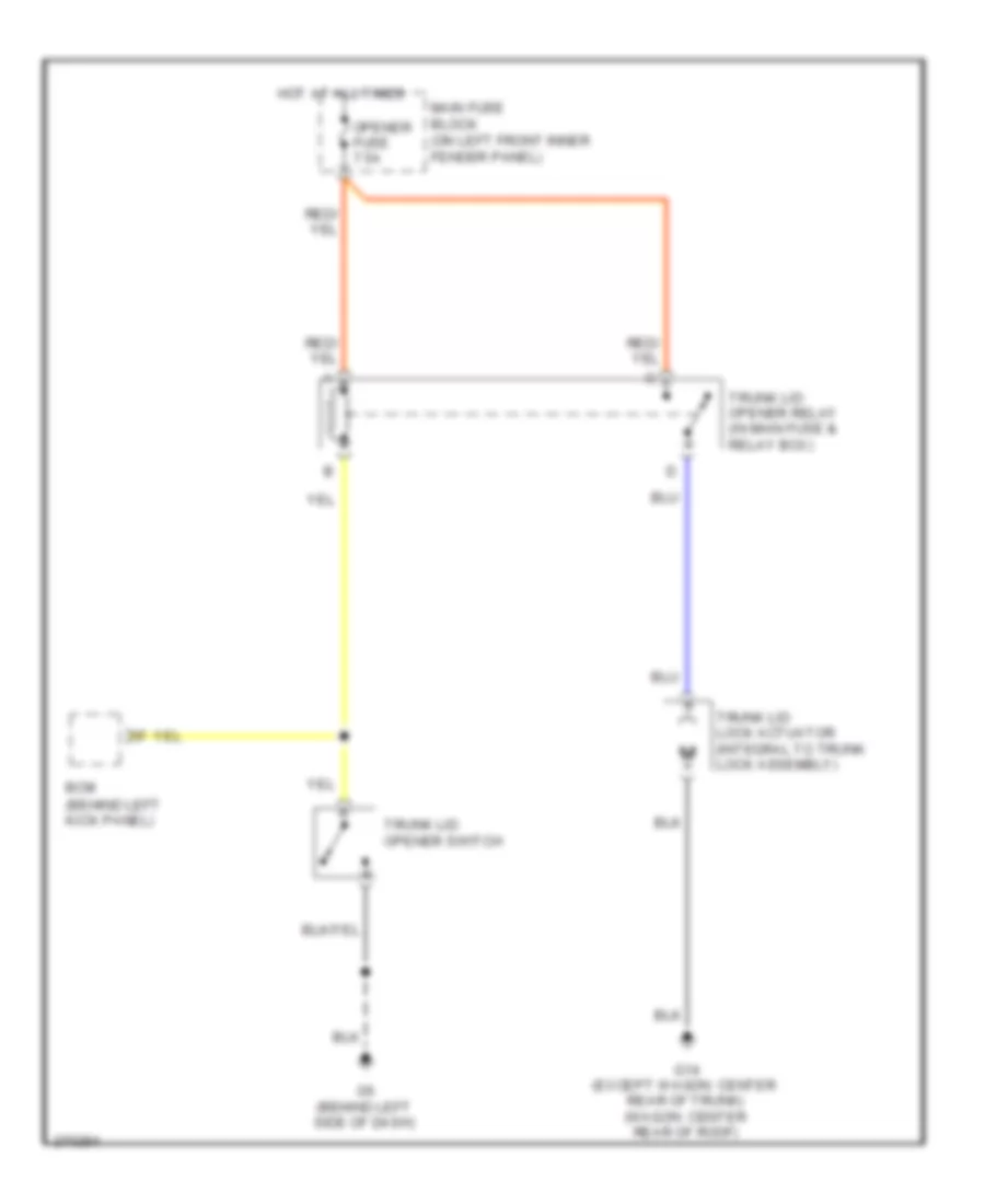
Forced Entry Wiring Diagram for Mazda 6 i Grand Touring 2008
List of elements for Forced Entry Wiring Diagram for Mazda 6 i Grand Touring 2008:
- (at rear of right front door)
- (at rear of right rear door)
- 5-door/wagon
- Bcm (behind left kick panel)
- D lock fuse 30a
- Door ind
- Fuse block (under left side of dash)
- G1 (left side of engine compt)
- G14 (center rear of trunk)
- G9 (behind right end of dash)
- Hood switch (front right center of engine compt)
- Hot at all times
- Instrument cluster
- Jc-01
- Jc-03
- Keyless control module (w/ advanced keyless system) (behind right end of dash)
- Left door lock switch
- Left front door lock link switch/ left door key cylinder switch/ left front door lock actuator (left front door lock actuator: at rear of left front door)
- Left front door switch (at left "b" pillar)
- Left rear door lock actuator (at rear of left rear door)
- Left rear door lock link switch (in left rear door)
- Left rear door switch (at left "c" pillar)
- Liftgate lock actuator (lower left side of liftgate)
- Right door lock switch
- Right front door lock actuator
- Right front door lock link switch (in right front door)
- Right front door switch (at right "b" pillar)
- Right rear door lock actuator
- Right rear door lock link switch (in right rear door)
- Right rear door switch (at right "c" pillar)
- Room fuse 15a
- Sport sedan
- Trunk key cylinder switch (sport sedan)
- Trunk lid opener (center rear of trunk lid)
- Unlk
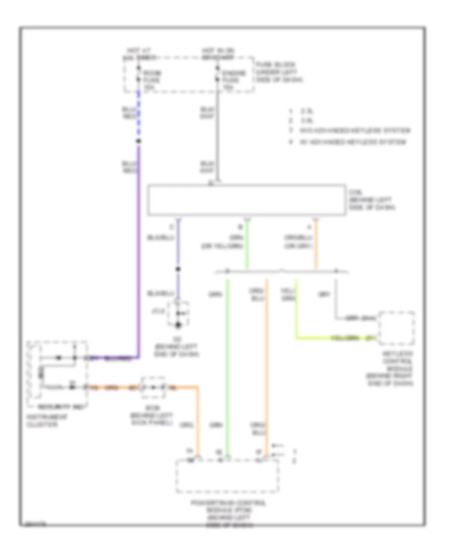
Immobilizer Wiring Diagram for Mazda 6 i Grand Touring 2008
List of elements for Immobilizer Wiring Diagram for Mazda 6 i Grand Touring 2008:
- 2.3l
- 2aa
- 3.0l
- Bcm (behind left kick panel)
- Coil (behind left side of dash)
- Engine fuse 15a
- Fuse block (under left side of dash)
- G2 (behind left end of dash)
- Hot at all times
- Hot in on or start
- Instrument cluster
- Jc-2
- Keyless control module (behind right end of dash)
- Mic
- Powertrain control module (pcm) (behind left side of dash)
- Room fuse 15a
- Security ind
- W/ advanced keyless system
- W/o advanced keyless system
BODY CONTROL MODULES
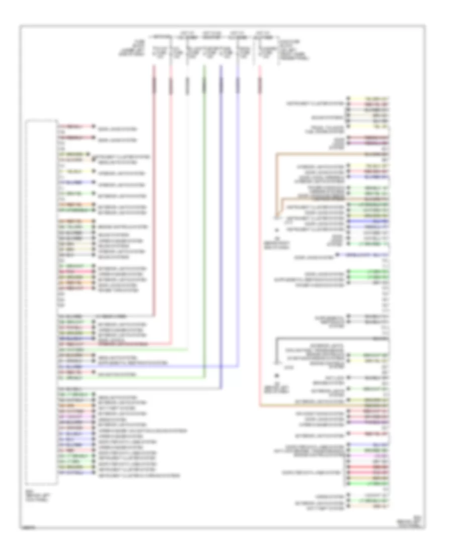
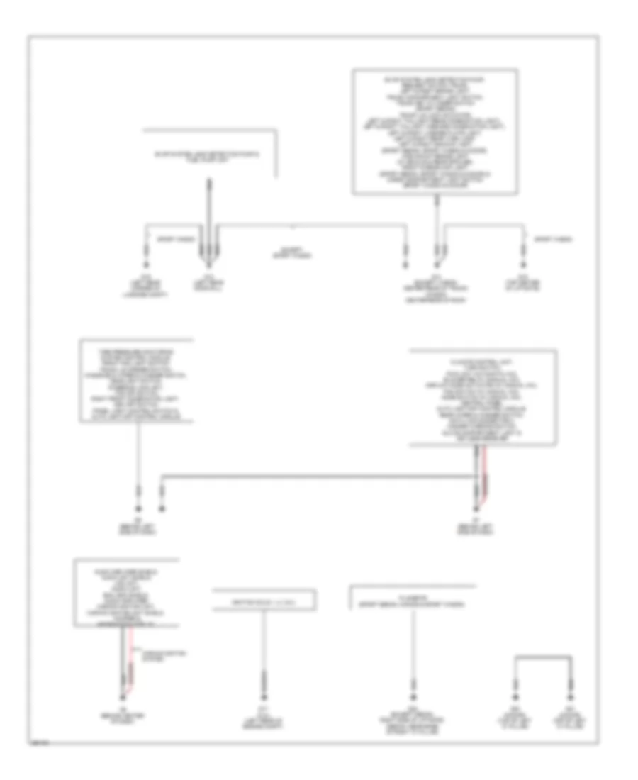
Body Control Modules Wiring Diagram for Mazda 6 i Grand Touring 2008
List of elements for Body Control Modules Wiring Diagram for Mazda 6 i Grand Touring 2008:
- (behind right end of dash)
- (w/ rear wiper)
- A/c fuse 10a
- Air conditioning system
- Anti-lock
- Anti-theft system
- Bcm (behind left kick panel)
- Brakes system
- Computer data lines system
- Computer data lines system anti-lock brakes, transmissions & engine controls system
- Cooling fans, transmissions, engine controls & starting/charging systems
- D lock fuse 30a
- Door locks & interior lights systems
- Door locks system
- Door locks, mirrors & interior lights systems
- Engine controls system
- Exterior lights system
- Exterior lights,
- Fuse block (under left side of dash)
- G2 (behind left end of dash)
- Hazard fuse 10a
- Headlights system
- Horns system
- Hot at all times
- Hot in on
- Hot in on or start
- Instrument cluster & warning systems
- Instrument cluster system
- Interior lights system
- J/c 3
- Jc-02
- Main fuse block (on left front inner fender panel)
- Meter fuse 15a
- Navigation system
- Pnk
- Power tops system
- Power windows & mirrors systems door locks & exterior lights systems
- Power windows system
- R wip fuse 10a
- Red
- Room fuse 15a
- Sas fuse 10a
- Sound systems
- Trunk, tailgate, fuel doors system
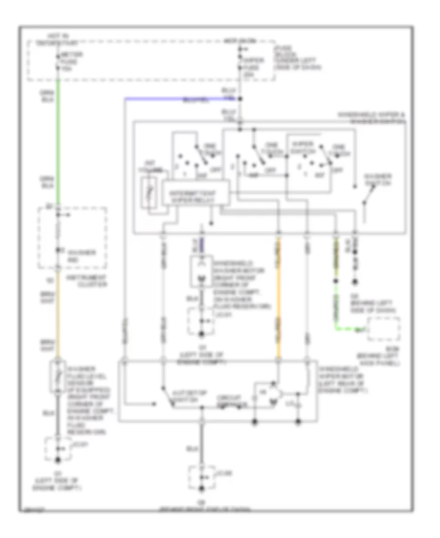
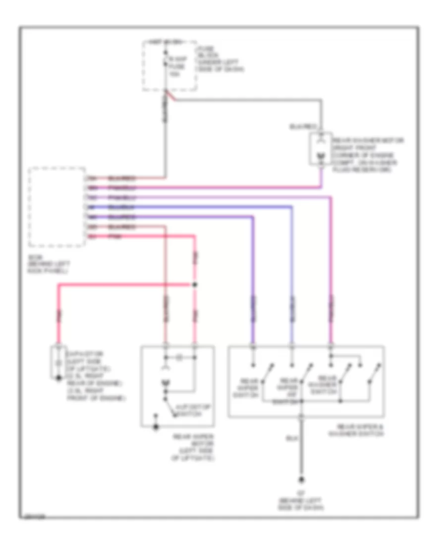
- Wiper/washer system
- Wiper/washer, navigation & sound systems
COMPUTER DATA LINES
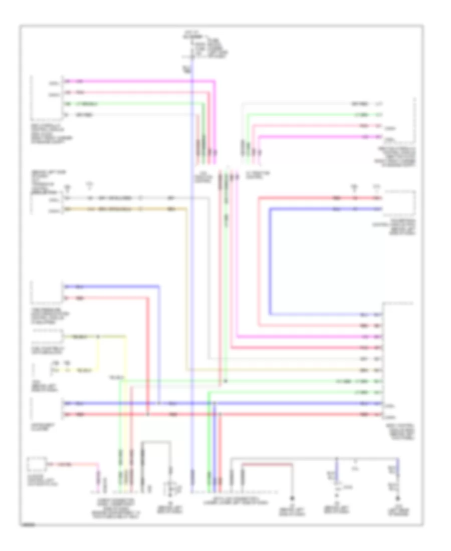
Computer Data Lines Wiring Diagram for Mazda 6 i Grand Touring 2008
List of elements for Computer Data Lines Wiring Diagram for Mazda 6 i Grand Touring 2008:
- (behind left side of dash) (a/t) transaxle control module (tcm)
- (w/ abs)
- 0740-215
- 1ai
- 1am
- 2.3l
- 3.0l
- A14
- Abs/tcs hydraulic control module (abs/tcs hu/cm) (right front corner of engine compt)
- Body control module (bcm) (behind left kick panel)
- Can-h
- Can-l
- Check connector (dash: under right side of dash) (engine compartment: in main fuse & relay box)
- Climate control unit (automatic a/c)
- D-02
- Data link connector 2 (under lower left side of dash)
- Dsc hydraulic control module (dsc hu/cm) (right front corner of engine compt)
- Fuel pump relay (on fuse block)
- Fuse block (under left side of dash)
- G15 (left rear of engine)
- G2 (behind left end of dash)
- G7 (behind left side of dash)
- Hot at all times
- Instrument cluster
- Jc-
- Jc-02
- Pcm (behind left side of dash)
- Pnk
- Powertrain control module (pcm) (behind left side of dash)
- Red
- Room fuse 15a
- Tire pressure monitoring system control module (if equipped)
- W/ traction control
- W/0 traction control
COOLING FAN
2.3L
2.3L, Cooling Fan Wiring Diagram for Mazda 6 i Grand Touring 2008
List of elements for 2.3L, Cooling Fan Wiring Diagram for Mazda 6 i Grand Touring 2008:
- 1au
- 2ah
- 2ay
- A/t
- Ad fan fuse 30a
- Bcm (behind left kick panel)
- Center panel/ hazard warning switch
- Cooling fan motor 1 (at left front of engine compt)
- Cooling fan motor 2 (at right front of engine compt)
- Cooling fan relay 1 (ad fan relay) (in main fuse & relay box)
- Cooling fan relay 2 (fan relay) (in main fuse & relay box)
- Cooling fan relay 3 (fan relay 3) (in main fuse & relay box)
- Cooling fan relay 4 (fan relay 2) (in main fuse & relay box)
- Engine coolant temperature sensor (left rear of engine)
- Exterior lights system
- Fan fuse 30a
- Fuse block (under left side of dash)
- G2 (behind left end of dash)
- G3 (right side of engine compartment)
- Hot at all times
- Hot in on or start
- Jc-02
- Low
- M/t
- Main fuse block (main fuse & relay box) (on left front inner fender panel)
- Meter fuse 15a
- Mid
- Pcm (behind left side of dash)
- Refrigerant pressure switch (right front corner of engine compt)
3.0L
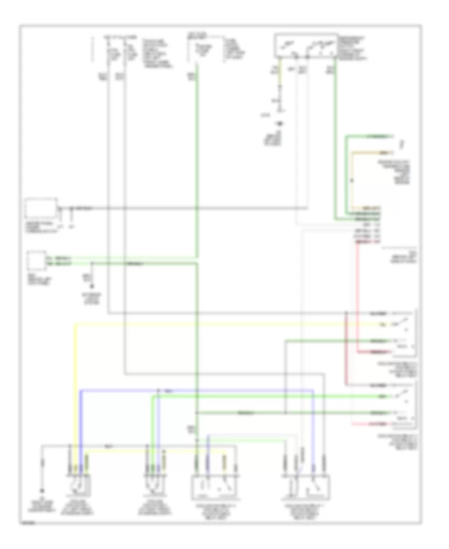
3.0L, Cooling Fan Wiring Diagram for Mazda 6 i Grand Touring 2008
List of elements for 3.0L, Cooling Fan Wiring Diagram for Mazda 6 i Grand Touring 2008:
- 1ah
- 1an
- 2ac
- 2aj
- A/t
- Center panel/ hazard warning switch
- Cooling fan motor 1 (at left front of engine compartment)
- Cooling fan motor 2 (at right front of engine compartment)
- Cooling fan relay (in main fuse & relay box)
- Eng bb fuse 5a
- Engine coolant temperature sensor (top rear of engine)
- Fan 1 fuse 30a
- Fan 2 fuse 30a
- Fan control module (behind left side of front grille)
- G2 (behind left end of dash)
- G4 (right front of engine compt)
- Hot at all times
- Hot w/ main relay power energized
- Jc-02
- Low
- M/t
- Main fuse block (main fuse & relay box) (on left front inner fender panel)
- Mid
- Nca
- Pcm (behind left side of dash)
- Red
- Refrigerant pressure switch (right front corner of engine compt)
CRUISE CONTROL
2.3L
2.3L, Cruise Control Wiring Diagram for Mazda 6 i Grand Touring 2008
List of elements for 2.3L, Cruise Control Wiring Diagram for Mazda 6 i Grand Touring 2008:
- (behind left end of dash)
- 1a0
- 1af
- 1ai
- 1aj
- 1al
- 1am
- 1ap
- 1aq
- 1as
- 1av
- 2ak
- 2al
- 2ao
- 2ap
- Accelerator pedal position sensor (on accelerator pedal assembly)
- At main relay (in main fuse & relay box)
- Brake switch 2 (on brake pedal assembly)
- Cancel switch
- Clock spring (in steering column)
- Clutch pedal position switch (top of clutch pedal assembly)
- Computer data lines system
- Cruise control main switch
- Cruise control switch
- Cruise main ind
- Cruise set ind
- Fuse block (under left side of dash)
- G2 (behind left end of dash)
- G9 (behind right end of dash)
- Hot at all times
- Hot in on or start
- Instrument cluster
- Jc-02
- Jc-03
- M/t
- Main fuse & relay box (on left front inner fender panel)
- Meter fuse 15a
- Microcomputer
- Nca
- Neutral switch (on transaxle)
- Position throttle
- Powertrain control module (behind left side of dash)
- Red
- Resume/accel switch
- Sensor
- Set/coast switch
- Tcm fuse 15a
- Throttle actuator
- Throttle body (left rear of engine)
- Transaxle control module (a/t) (behind left side of dash)
- Transmissions system
- Vehicle speed sensor (a/t) (on transaxle)
- Vehicle speed sensor (m/t) (on transaxle)
3.0L
3.0L, Cruise Control Wiring Diagram for Mazda 6 i Grand Touring 2008
List of elements for 3.0L, Cruise Control Wiring Diagram for Mazda 6 i Grand Touring 2008:
- 1ab
- 1ad
- 1af
- 1ap
- 1ar
- 1as
- 1av
- 2ai
- 2am
- 2an
- 2ar
- A14
- Accelerator pedal position sensor (on accelerator pedal assembly)
- B19
- B20
- Brake switch 2 (on brake pedal assembly)
- Cancel switch
- Clock spring (in steering column)
- Clutch pedal position switch (top of clutch pedal assembly)
- Computer data lines system
- Crankshaft position sensor (right front of engine)
- Cruise control main switch
- Cruise control switch
- Cruise main ind
- Cruise set ind
- Fuse block (under left side of dash)
- G2 (behind left end of dash)
- G9 (behind right end of dash)
- Hot in on or start
- Instrument cluster
- Jc-02
- Jc-03
- M/t
- Meter fuse 15a
- Microcomputer
- Nca
- Neutral switch (on transaxle)
- Powertrain control module (behind left side of dash)
- Red
- Resume/accel switch
- Set/coast switch
- Throttle actuator
- Throttle body (left rear of engine)
- Throttle position sensor
- Transaxle control module (a/t) (behind left side of dash)
- Vehicle speed sensor (a/t) (on transaxle)
DEFOGGERS
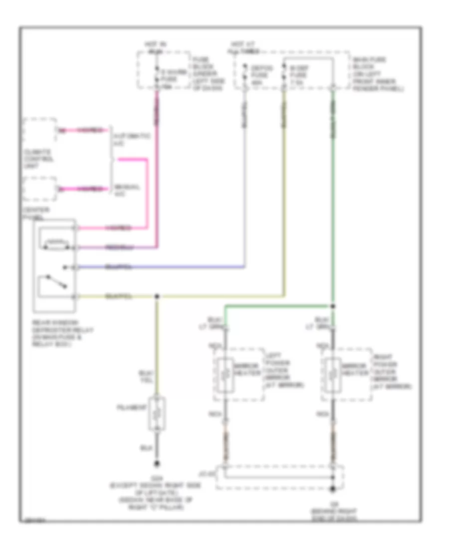
Defoggers Wiring Diagram for Mazda 6 i Grand Touring 2008
List of elements for Defoggers Wiring Diagram for Mazda 6 i Grand Touring 2008:
- Automatic a/c
- Center panel
- Climate control unit
- Defog fuse 40a
- Filament
- Fuse block (under left side of dash)
- G24 (except sedan: right side of liftgate) (sedan: near base of right ''c'' pillar)
- G9 (behind right end of dash)
- Hot at all times
- Hot in run
- Jc-03
- Left power outer mirror (at mirror)
- M def fuse 7.5a
- Main fuse block (on left front inner fender panel)
- Manual a/c
- Mirror heater
- Nca
- Rear window defroster relay (in main fuse & relay box)
- Right power outer mirror (at mirror)
- S warm fuse 15a
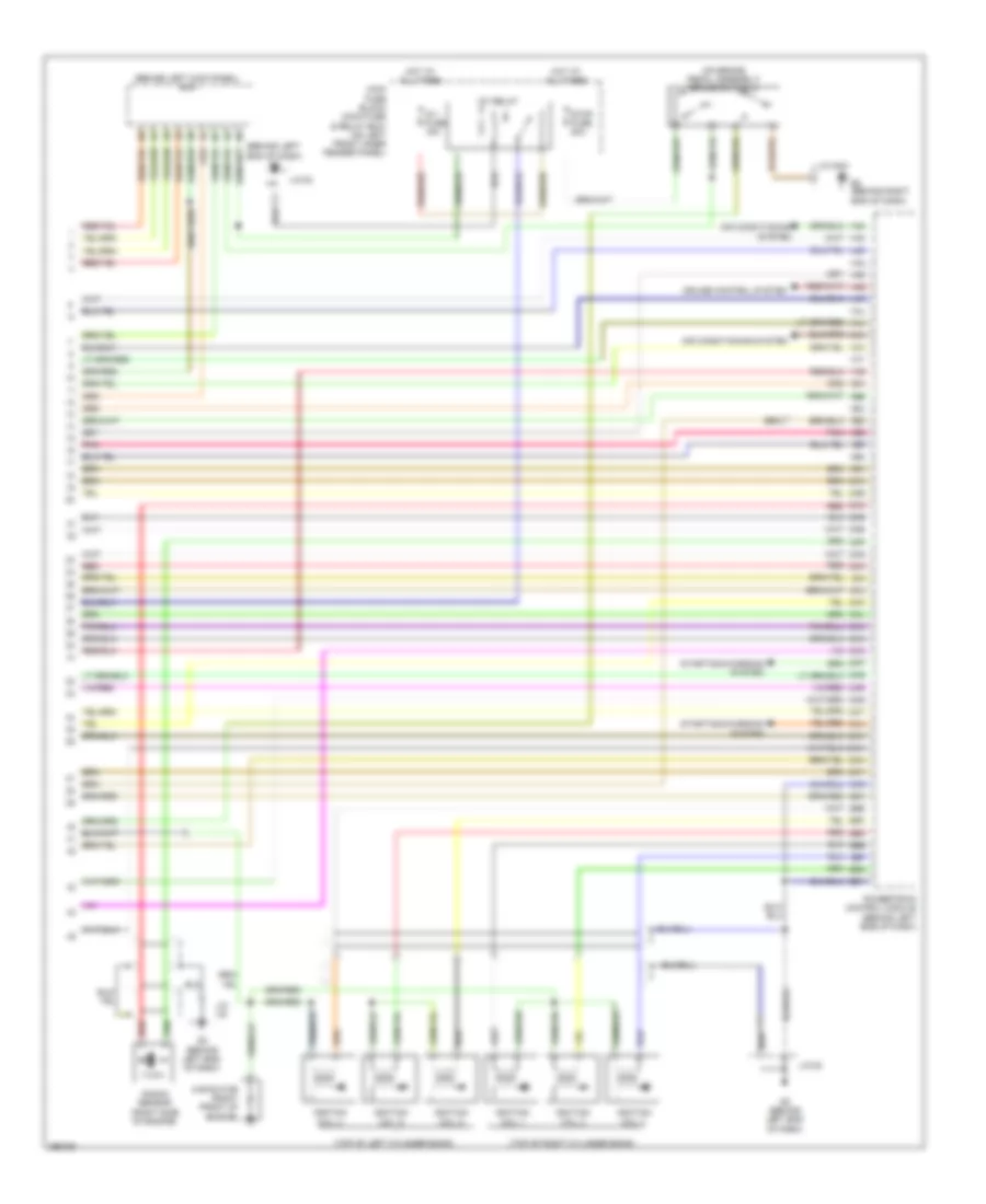
ENGINE PERFORMANCE
2.3L
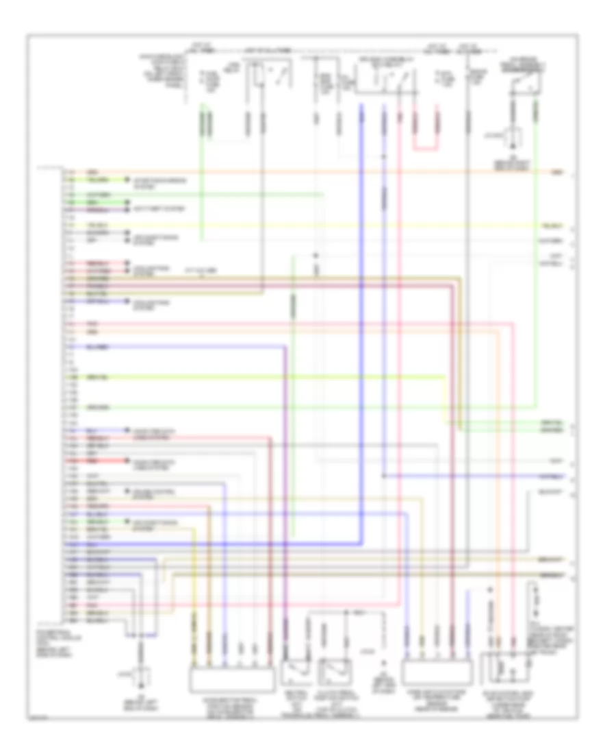
2.3L, Engine Performance Wiring Diagram, California (1 of 3) for Mazda 6 i Grand Touring 2008
List of elements for 2.3L, Engine Performance Wiring Diagram, California (1 of 3) for Mazda 6 i Grand Touring 2008:
- (on brake pedal assembly) brake switch 2
- 1aa
- 1ab
- 1ac
- 1ad
- 1ae
- 1af
- 1ag
- 1ah
- 1ai
- 1aj
- 1ak
- 1al
- 1am
- 1an
- 1ao
- 1ap
- 1aq
- 1ar
- 1as
- 1at
- 1au
- 1av
- 1aw
- 1ax
- 1ay
- 1az
- 1ba
- 1bb
- 1bc
- 1bd
- 1be
- 1bf
- 1bg
- 1bh
- Accelerator pedal position sensor (on accelerator pedal assembly)
- Air conditioning system
- Anti-theft system
- Clutch pedal position switch (m/t) (top of clutch pedal assembly)
- Computer data lines system
- Cooling fans system
- Cruise control system
- Drive-by-wire-relay (etc relay)
- Eng bar fuse 10a
- Eng+b fuse 7.5a
- Etc fuse 7.5a
- Evap system leak detection pump (under rear of vehicle, near fuel pump)
- Fuel pump fuse 15a
- G2 (behind left end of dash)
- G9 (behind right end of dash)
- Hot at all times
- Inj fuse 15a
- J/c g-03
- J/c-02
- M/t w/o abs
- Main fuse block (main fuse & relay box) (on left front inner fender panel)
- Main relay
- Mass air flow/intake air temperature sensor (rear of engine)
- Nca
- Neutral switch (m/t) (on transaxle)
- Pnk
- Powertrain control module (pcm) (behind left side of dash)
- Red
- Starting/charging system
2.3L, Engine Performance Wiring Diagram, California (2 of 3) for Mazda 6 i Grand Touring 2008
List of elements for 2.3L, Engine Performance Wiring Diagram, California (2 of 3) for Mazda 6 i Grand Touring 2008:
- (in main fuse & relay box) check connector
- (left side of engine, below power steering pump) knock sensor
- Body control module (bcm) (behind left kick panel)
- Engine coolant temperature sensor (left rear of engine)
- Engine fuse 15a
- Front heated oxygen sensor (left rear of engine compt)
- Fuel pump
- Fuel pump relay
- Fuel pump unit
- Fuse block (under left side of dash)
- G12 (left rear door sill)
- G2 (behind left end of dash)
- Hot in run or start
- Instrument cluster
- J/c-02
- Manifold absolute pressure sensor (left rear of engine)
- Meter fuse 15a
- Micro computer
- Middle heated oxygen sensor (left rear of engine compt)
- Mil ind
- Nca
- Oil control valve (right front of engine)
- Rear ho2s (left rear of engine compt)
- Sender unit fuel gauge
- Variable intake air solenoid valve (left front of engine)
- Variable tumble shutter valve switch (left side of engine compt)
- Variable tumble solenoid valve (left front side of engine)
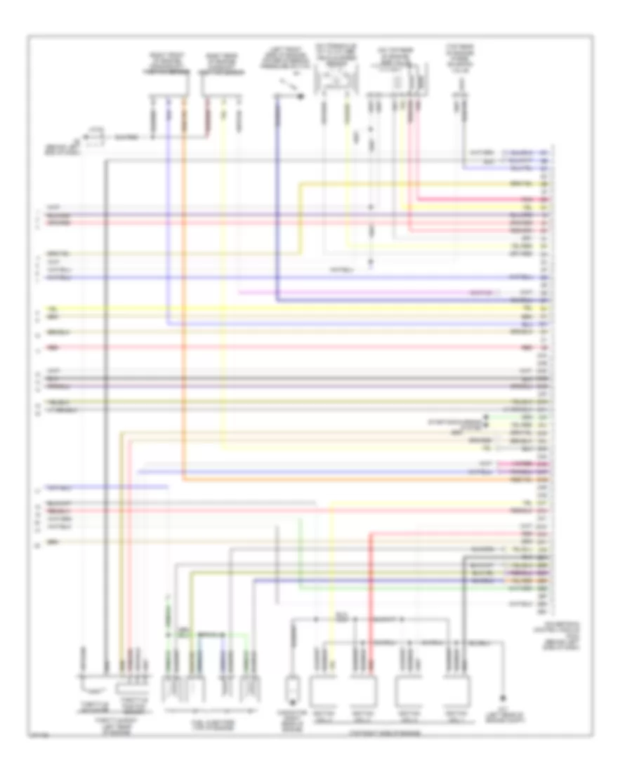
2.3L, Engine Performance Wiring Diagram, California (3 of 3) for Mazda 6 i Grand Touring 2008
List of elements for 2.3L, Engine Performance Wiring Diagram, California (3 of 3) for Mazda 6 i Grand Touring 2008:
- (left front side of engine) power steering pressure switch
- (left rear of engine)
- (on top rear of engine) egr valve
- (on transaxle) (m/t & w/o abs) vehicle speed sensor
- (right front of engine) crankshaft position sensor
- (right rear of engine) camshaft position sensor
- (top rear of engine) purge solenoid valve
- (top right side of engine)
- 2aa
- 2ab
- 2ac
- 2ad
- 2ae
- 2af
- 2ag
- 2ah
- 2ai
- 2aj
- 2ak
- 2al
- 2am
- 2an
- 2ao
- 2ap
- 2aq
- 2ar
- 2as
- 2at
- 2au
- 2av
- 2aw
- 2ax
- 2ay
- 2az
- 2ba
- 2bb
- 2bc
- 2bd
- 2be
- 2bf
- 2bg
- 2bh
- Capacitor (right rear of engine)
- Fuel injectors (top of engine)
- G17 (left rear of engine compt)
- G2 (behind left end of dash)
- Ignition coil 1
- Ignition coil 2
- Ignition coil 3
- Ignition coil 4
- J/c-02
- Pnk
- Powertrain control module (pcm) (behind left side of dash)
- Red
- Starting/charging system
- Throttle actuator
- Throttle body
- Throttle position sensor
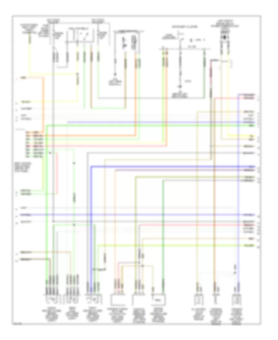
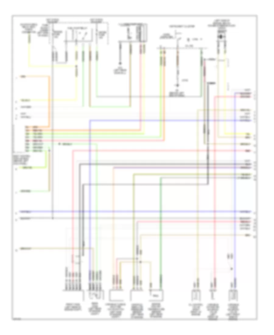
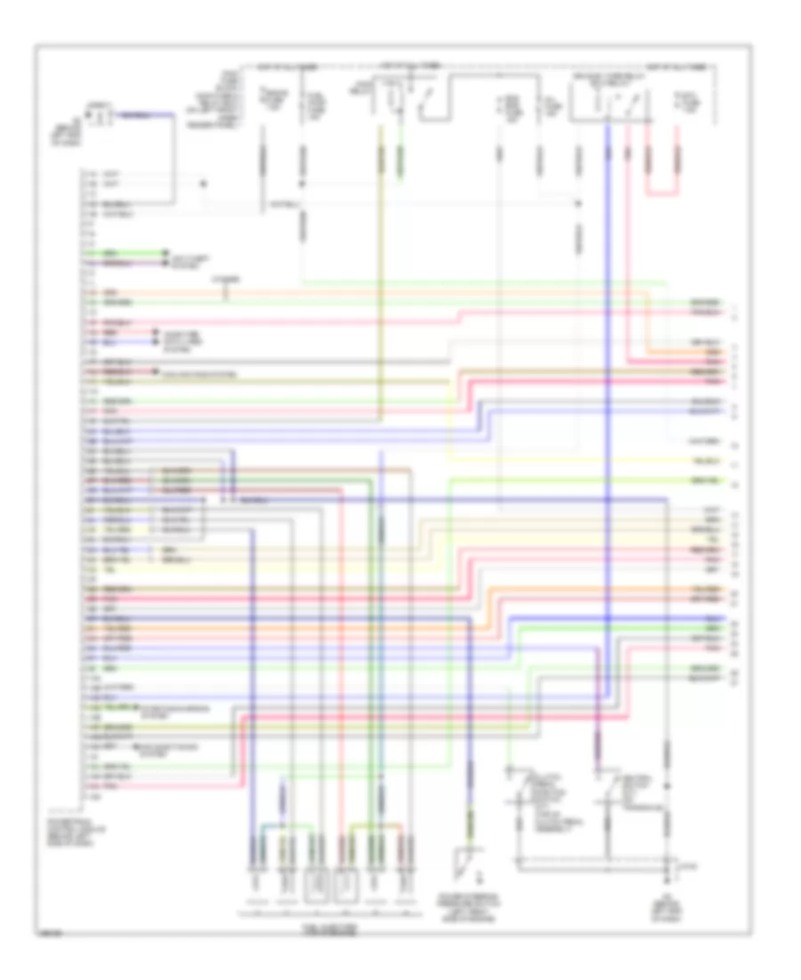
2.3L, Engine Performance Wiring Diagram, Except California (1 of 3) for Mazda 6 i Grand Touring 2008
List of elements for 2.3L, Engine Performance Wiring Diagram, Except California (1 of 3) for Mazda 6 i Grand Touring 2008:
- (on brake pedal assembly) brake switch 2
- 1aa
- 1ab
- 1ac
- 1ad
- 1ae
- 1af
- 1ag
- 1ah
- 1ai
- 1aj
- 1ak
- 1al
- 1am
- 1an
- 1ao
- 1ap
- 1aq
- 1ar
- 1as
- 1at
- 1au
- 1av
- 1aw
- 1ax
- 1ay
- 1az
- 1ba
- 1bb
- 1bc
- 1bd
- 1be
- 1bf
- 1bg
- 1bh
- Accelerator pedal position sensor (on accelerator pedal assembly)
- Air conditioning system
- Anti-theft system
- Clutch pedal position switch (m/t) (top of clutch pedal assembly)
- Computer data lines system
- Cooling fans system
- Cruise control system
- Drive-by-wire-relay (etc relay)
- Eng bar fuse 15a
- Eng+b fuse 7.5a
- Etc fuse 7.5a
- Evap system leak detection pump (under rear of vehicle, near fuel pump)
- Fuel pump fuse 15a
- G14 (wagon: center rear of roof) (except wagon: center rear of trunk)
- G2 (behind left end of dash)
- G9 (behind right end of dash)
- Hot at all times
- Inj fuse 15a
- J/c g-03
- J/c-02
- M/t w/o abs
- Main fuse block (main fuse & relay box) (on left front inner fender panel)
- Main relay
- Mass air flow/intake air temperature sensor (rear of engine)
- Nca
- Neutral switch (m/t) (on transaxle)
- Pnk
- Powertrain control module (pcm) (behind left side of dash)
- Red
- Starting/charging system
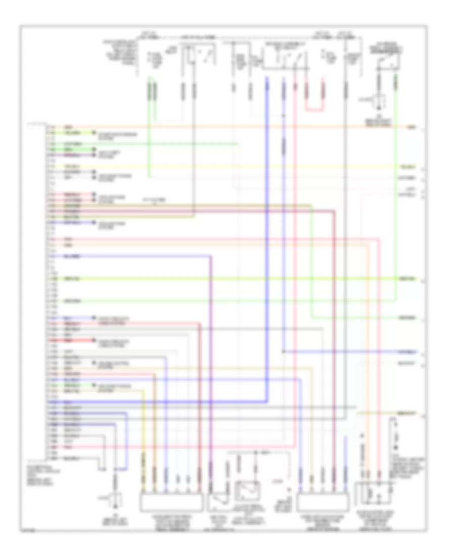
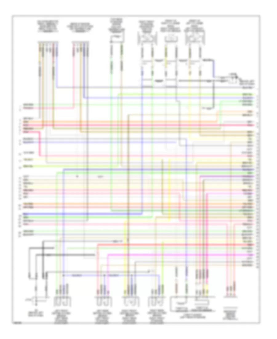
2.3L, Engine Performance Wiring Diagram, Except California (2 of 3) for Mazda 6 i Grand Touring 2008
List of elements for 2.3L, Engine Performance Wiring Diagram, Except California (2 of 3) for Mazda 6 i Grand Touring 2008:
- (in main fuse & relay box) check connector
- (left side of engine, below power steering pump) knock sensor
- Body control module (bcm) (behind left kick panel)
- Engine coolant temperature sensor (left rear of engine)
- Engine fuse 15a
- Front ho2s (left rear of engine compt)
- Fuel pump
- Fuel pump relay
- Fuel pump unit
- Fuse block (under left side of dash)
- G12 (left rear door sill)
- G2 (behind left end of dash)
- Hot in run or start
- Instrument cluster
- J/c-02
- Manifold absolute pressure sensor (left rear of engine)
- Meter fuse 15a
- Micro computer
- Mil ind
- Nca
- Oil control valve (right front of engine)
- Rear ho2s (left rear of engine compt)
- Red
- Sender unit fuel gauge
- Variable intake air solenoid valve (left front of engine)
- Variable tumble shutter valve switch (left side of engine compt)
- Variable tumble solenoid valve (left front side of engine)
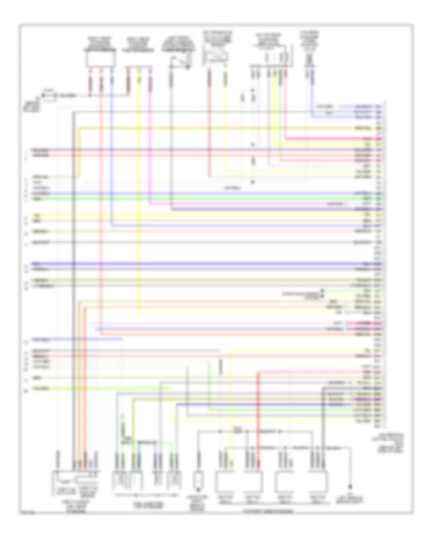
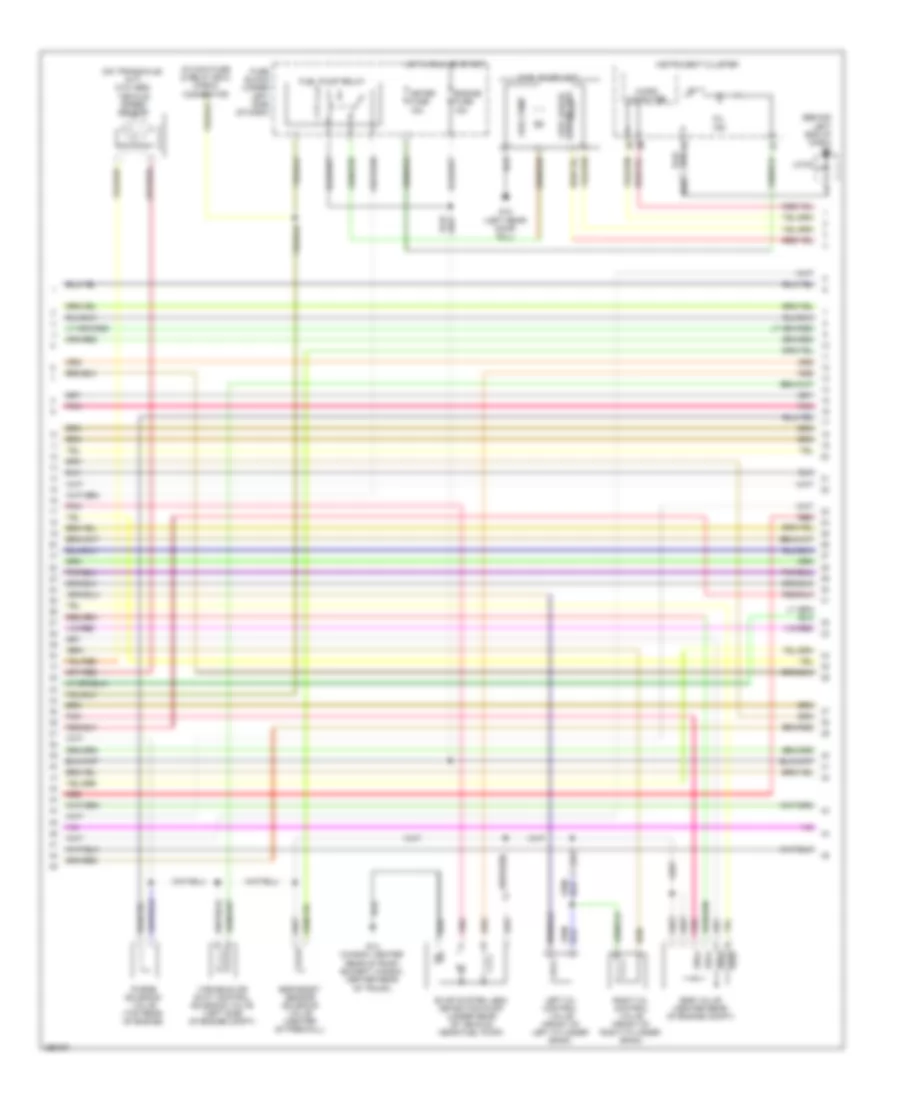
2.3L, Engine Performance Wiring Diagram, Except California (3 of 3) for Mazda 6 i Grand Touring 2008
List of elements for 2.3L, Engine Performance Wiring Diagram, Except California (3 of 3) for Mazda 6 i Grand Touring 2008:
- (left front side of engine) power steering pressure switch
- (left rear of engine)
- (on top rear of engine) egr valve
- (on transaxle) (m/t & w/o abs) vehicle speed sensor
- (right front of engine) crankshaft position sensor
- (right rear of engine) camshaft position sensor
- (top rear of engine) purge solenoid valve
- (top right side of engine)
- 2aa
- 2ab
- 2ac
- 2ad
- 2ae
- 2af
- 2ag
- 2ah
- 2ai
- 2aj
- 2ak
- 2al
- 2am
- 2an
- 2ao
- 2ap
- 2aq
- 2ar
- 2as
- 2at
- 2au
- 2av
- 2aw
- 2ax
- 2ay
- 2az
- 2ba
- 2bb
- 2bc
- 2bd
- 2be
- 2bf
- 2bg
- 2bh
- Capacitor (right rear of engine)
- Fuel injectors (top of engine)
- G17 (left rear of engine compt)
- G2 (behind left end of dash)
- Ignition coil 1
- Ignition coil 2
- Ignition coil 3
- Ignition coil 4
- J/c-02
- Pnk
- Powertrain control module (pcm) (behind left side of dash)
- Red
- Starting/charging system
- Throttle actuator
- Throttle body
- Throttle position sensor
3.0L
3.0L, Engine Performance Wiring Diagram (1 of 4) for Mazda 6 i Grand Touring 2008
List of elements for 3.0L, Engine Performance Wiring Diagram (1 of 4) for Mazda 6 i Grand Touring 2008:
- 1aa
- 1ab
- 1ac
- 1ad
- 1ae
- 1af
- 1ag
- 1ah
- 1ai
- 1aj
- 1ak
- 1al
- 1am
- Air conditioning system
- Anti-theft system
- Clutch pedal position switch (m/t) (top of clutch pedal assembly)
- Computer data lines system
- Cooling fans system
- Drive by wire relay (etc relay)
- Eng bar fuse 15a
- Eng+b fuse 7.5a
- Etc fuse 7.5a
- Fuel injectors (top of engine)
- Fuel pump fuse 15a
- G2 (behind left end of dash)
- Hot at all times
- Inj fuse 15a
- J/c-02
- Main fuse block (main fuse & relay box) (on left front inner fender panel)
- Main relay
- Neutral switch (m/t) (on transaxle)
- Pnk
- Power steering pressure switch (left front side of engine)
- Powertrain control module (behind left side of dash)
- Red
- Starting/charging system
- W/o abs
3.0L, Engine Performance Wiring Diagram (2 of 4) for Mazda 6 i Grand Touring 2008
List of elements for 3.0L, Engine Performance Wiring Diagram (2 of 4) for Mazda 6 i Grand Touring 2008:
- (front of left cylinder bank) left camshaft position sensor
- (front of right cylinder bank) right camshaft position sensor
- (on accelerator pedal assembly) accelerator pedal position sensor
- (rear of engine) mass air flow/intake air temperature sensor
- (right front of engine) crankshaft position sensor
- (top rear of engine) engine coolant temperature sensor
- Egr boost sensor (center of firewall)
- G2 (behind left end of dash)
- J/c-02
- Left front heated oxygen sensor (left rear of engine, in exhaust)
- Left rear heated oxygen sensor (left front of engine, in exhaust)
- Nca
- Pnk
- Red
- Right front heated oxygen sensor (right rear of engine, in exhaust)
- Right rear heated oxygen sensor (right front of engine, in exhaust)
- Throttle actuator
- Throttle body (left rear of engine)
- Throttle position sensor
3.0L, Engine Performance Wiring Diagram (3 of 4) for Mazda 6 i Grand Touring 2008
List of elements for 3.0L, Engine Performance Wiring Diagram (3 of 4) for Mazda 6 i Grand Touring 2008:
- (behind left end of dash) g2
- (in main fuse & relay box) check connector
- (on transaxle) (m/t) (w/o abs) vehicle speed sensor
- Egr boost sensor solenoid valve (center of firewall)
- Egr valve (center rear of engine compt)
- Engine fuse 15a
- Evap system leak detection pump (under rear of vehicle, near fuel pump)
- Fuel pump
- Fuel pump relay
- Fuel pump unit
- Fuse block (under left side of dash)
- G12 (left rear door sill)
- G14 (wagon: center rear of roof) (except wagon: center rear of trunk)
- Hot in run or start
- Instrument cluster
- J/c-02
- Left oil control valve (front of left cylinder bank)
- Meter fuse 15a
- Micro computer
- Mil ind
- Pnk
- Purge solenoid valve (top rear of engine)
- Red
- Right oil control valve (front of right cylinder bank)
- Sender unit fuel gauge
- Variable air duct control solenoid valve (left side of engine compt)
3.0L, Engine Performance Wiring Diagram (4 of 4) for Mazda 6 i Grand Touring 2008
List of elements for 3.0L, Engine Performance Wiring Diagram (4 of 4) for Mazda 6 i Grand Touring 2008:
- (behind left end of dash) g2
- (behind left kick panel) bcm
- (on brake pedal assembly) brake switch 2
- (top of left cylinder bank)
- (top of right cylinder bank)
- (w/o abs)
- 1an
- 1ao
- 1ap
- 1aq
- 1ar
- 1as
- 1at
- 1au
- 1av
- 1aw
- 1ax
- 1ay
- 1az
- 1ba
- 1bb
- 1bc
- 1bd
- 1be
- 1bf
- 1bg
- 1bh
- 2aa
- 2ab
- 2ac
- 2ad
- 2ae
- 2af
- 2ag
- 2ah
- 2ai
- 2aj
- 2ak
- 2al
- 2am
- 2an
- 2ao
- 2ap
- 2aq
- 2ar
- 2as
- 2at
- 2au
- 2av
- 2aw
- 2ax
- 2ay
- 2az
- 2ba
- 2bb
- 2bc
- 2bd
- 2be
- 2bf
- 2bg
- 2bh
- Air conditioning system
- Capacitor (right front of engine)
- Cruise control system
- G2 (behind left end of dash)
- G9 (behind right end of dash)
- Hot at all times
- Ig 1 fuse 15a
- Ig1 relay
- Ignition coil 1
- Ignition coil 2
- Ignition coil 3
- Ignition coil 4
- Ignition coil 5
- Ignition coil 6
- J/c -02
- J/c g-03
- J/c-02
- Knock sensor (right side of engine)
- Main fuse block (main fuse & relay box) (on left front inner fender panel)
- Pnk
- Powertrain control module (behind left side of dash)
- Red
- Starting/charging system
- Stop fuse 20a
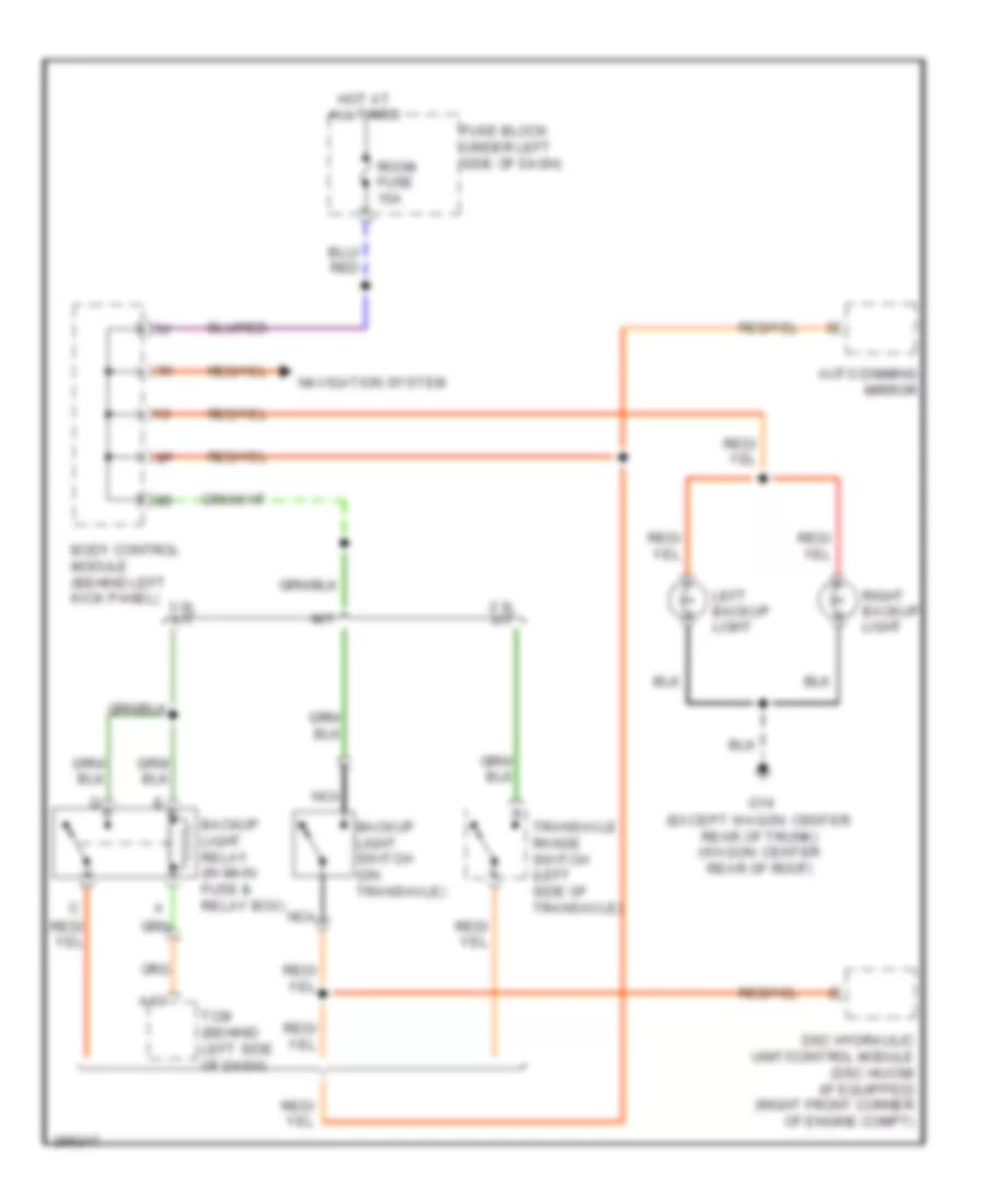
EXTERIOR LIGHTS
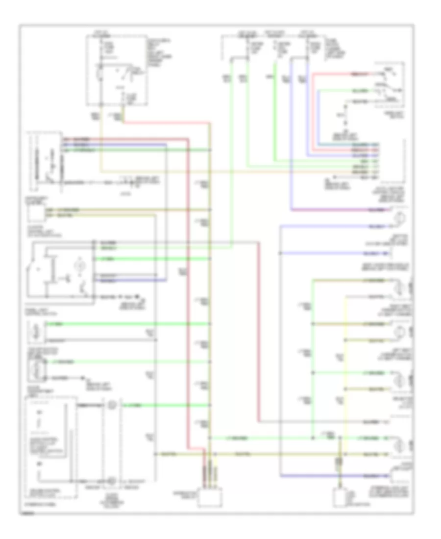
Backup Lamps Wiring Diagram for Mazda 6 i Grand Touring 2008
List of elements for Backup Lamps Wiring Diagram for Mazda 6 i Grand Touring 2008:
- (except wagon: center rear of trunk) (wagon: center rear of roof)
- 2.3l a/t
- 3.0l a/t
- A13
- Auto dimming mirror
- Backup light relay (in main fuse & relay box)
- Backup light switch (on transaxle)
- Body control module (behind left kick panel)
- Dsc hydraulic unit/control module (dsc hu/cm) (if equipped) (right front corner of engine compt)
- Fuse block (under left side of dash)
- G14
- Hot at all times
- Left backup light
- M/t
- Navigation system
- Nca
- Right backup light
- Room fuse 15a
- Tcm (behind left side of dash)
- Transaxle range switch (left side of transaxle)
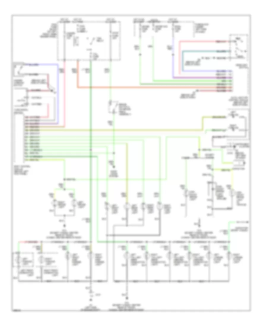
Exterior Lamps Wiring Diagram for Mazda 6 i Grand Touring 2008
List of elements for Exterior Lamps Wiring Diagram for Mazda 6 i Grand Touring 2008:
- (behind
- (behind left side of dash)
- 5 door
- Auto light-off control module (behind left side of dash)
- Body control module (behind left kick panel)
- Brake switch 2 (on brake pedal assembly)
- Capacitor
- Capacitor (sport wagon)
- Door locks system
- Except 5 door
- Fuse block (under left side of dash)
- G1 (left side of engine compt)
- G14 (except wagon: center rear of trunk) (wagon: center rear of roof)
- G6 (behind left side of dash)
- G7 (behind left side of dash)
- Hazard fuse 10a
- Hazard warning switch
- Head
- Headlight switch
- High mount brake light
- High mount brake light (in vehicle)
- High mount brake light (rear spoiler)
- Hot at all times
- Hot in acc or run
- Hot in on or start
- Instrument cluster
- Jc-01
- Jc-02
- Left brake light
- Left end of dash)
- Left front combination light
- Left front side marker light
- Left front turn light
- Left license plate light
- Left parking light
- Left rear turn light
- Left taillight (inboard combination light)
- Left taillight (rear combination light)
- Left turn ind
- Main fuse 120a
- Main fuse block (on left front inner fender panel)
- Meter acc fuse 5a
- Meter fuse 15a
- Nca
- Off
- Right brake light
- Right front combination light
- Right front side marker light
- Right front turn light
- Right license plate light
- Right parking light
- Right rear turn light
- Right taillight (inboard combination light)
- Right taillight (rear combination light)
- Right turn ind
- Room fuse 15a
- Stop fuse 20a
- Tail fuse 10a
- Tns
- Tns relay
- Turn signal switch
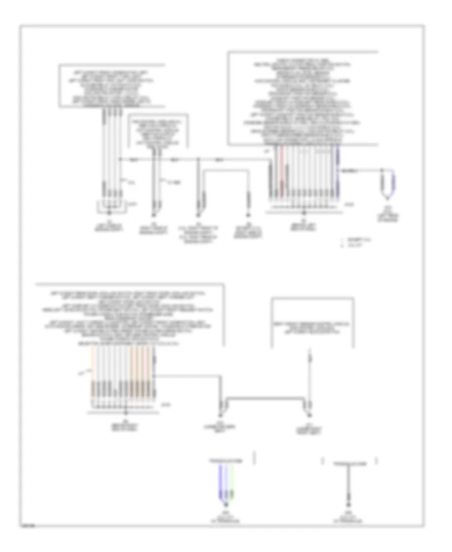
GROUND DISTRIBUTION
Ground Distribution Wiring Diagram (1 of 2) for Mazda 6 i Grand Touring 2008
List of elements for Ground Distribution Wiring Diagram (1 of 2) for Mazda 6 i Grand Touring 2008:
- (2.3l: right rear of engine compt)
- (left side of engine compt)
- 2.3l
- 3.0l a/t
- A/t
- Check connector (w/ abs), neutral switch, clutch pedal position switch, refrigerant pressure switch, brake fluid level sensor, intermediate sensor (2.3l), awd control module, bcm, instrument cluster, pcm shield (3.0l), ig1 relay (3.0l), knock sensor shield (3.0l), crankshaft position sensor (2.3l), camshaft position sensor (2.3l), ho2s(left front) & ho2s(left rear) shield (3.0l), ho2s(right front) & ho2s(right rear) shield (3.0l), crankshaft position sensor shield (3.0l), left & right camshaft position sensor shield (3.0l), woofer relay (bose relay), pcm, coil, combined sensor shield (w/ dsc), dsc hu/cm shield (w/ dsc), ignition coils 1, 2, 3, 4, 5 & 6 shield (3.0l), vehicle speed sensor (2.3l), cooling fan relay (3.0l), input/turbine speed sensor shield (2.3l), data link connector 2, clock spring & transaxle control module (2.3l & 3.0l)
- Except 2.3l
- G10 (under driver's seat)
- G11 (under right front seat)
- G15 (3.0l) (left rear of engine)
- G2 (behind left end of dash)
- G23 (2.3l a/t) (in transaxle)
- G25 (2.3l a/t) (in transaxle)
- G3 (right side of engine compt)
- G4 (3.0l: right front of engine compt)
- G5 (except 2.3l) (right side of engine compt)
- G9 (behind right end of dash)
- Jc-01
- Jc-02
- Jc-03
- Left & right front combination light, left & right front turn light, left & right front fog light, hood switch, blower relay (automatic a/c), windshield washer motor, cooling fan motor 1, 2 (2.3l), cooling fan relay 4 (fan 2 relay) (2.3l), left & right front side marker light & washer fluid-level sensor
- Left & right rear door lock-link switch, right front door lock-link switch, left & right seat warmer switch, left & right seat warmer unit left & right door lock switch, left door key cylinder switch/left front door lock-link switch, headlight leveling switch, power seat switch, left & right front request switch, power window sub switch (passenger side), rear accessory socket,
- Left & right vanity mirror illumination, left & right front combination light, auto dimming mirror, keyless buzzer, accessory socket, windshield wiper motor left & right heated outer mirror, power outer mirror switch, brake switch 2, bcm, keyless control module, power window main switch & selector lever component (sport a/t) (2.3l & 3.0l)
- Seat weight sensor control module, sas control module & left & right buckle switch
- Transaxle case
- W/ abs
Ground Distribution Wiring Diagram (2 of 2) for Mazda 6 i Grand Touring 2008
List of elements for Ground Distribution Wiring Diagram (2 of 2) for Mazda 6 i Grand Touring 2008:
- (sport sedan, 5-door & sport wagon)
- Audio amplifier shield, audio unit shield, lcd unit, audio unit, bcm, bcm shield, audio amplifier, car-navigation unit, car-navigation unit shield, woofer & information display
- Car-navigation system
- Climate control unit, turn switch, pwm unit (automatic a/c), blower relay (manual a/c), airflow mode actuator (w/ manual a/c), fan switch (w/ manual a/c), mode switch (w/ manual a/c), central panel, auto light-off control module, rear wiper & washer switch, data link connector 2, hazard warning switch, glove compartment light & keyless receiver
- Evap system leak detection pump & fuel pump unit
- Evap system leak detection pump, request switch trunk, left & right brake light, trunk compartment light switch, trunk key cylinder switch (sport sedan), trunk lid lock actuator, left & right taillight (rear combination light), left & right taillight (inboard combination light), left & right license plate light, left & right rear turn light, left & right backup light (sport sedan, sport wagon & 5-door), high-mount brake light (in vehicle & rear spoiler), front & rear map light (sport sedan, sport wagon & 5-door) & cargo compartment light switch (sport wagon & 5-door)
- Except sport wagon
- Filaments
- G12 (left rear door sill)
- G14 (except wagon: center rear of trunk) (wagon: center rear of roof)
- G17 (2.3l) (left rear of engine compt)
- G18 (top center of liftgate)
- G19 (left rear corner of luggage compt)
- G20 (5-door) (top of left "c" pillar)
- G21 (5-door) (top of left "c" pillar)
- G24 (except sedan: right side of liftgate) (sedan: near base of right "c" pillar)
- G6 (behind left side of dash)
- G7 (behind left side of dash)
- G8 (behind center of dash)
- Ignition coils 1, 2, 3 & 4
- Sport wagon
- Tire pressure monitoring system control module, front fog light switch, trunk lid opener switch, windshield wiper & washer switch, headlight switch, steering lock unit, tcs off switch, right front combination light, dsc off switch, panel light control switch & auto light-off control module
HEADLIGHTS
Headlights Wiring Diagram, with DRL for Mazda 6 i Grand Touring 2008
List of elements for Headlights Wiring Diagram, with DRL for Mazda 6 i Grand Touring 2008:
- (behind left headlight assembly)
- (discharge)
- (if equipped)
- Auto light-off control module (behind left side of dash)
- Discharge headlight control module (if equipped) (behind right headlight assembly)
- Drl fusible link 20a
- Exterior lights system
- Flash headlight switch
- Flash to pass switch
- Fog fuse 15a
- Front fog light relay (in main fuse & relay box)
- Front fog light switch
- Fuse block (under left side of dash)
- G1 (left side of engine compt)
- G6 (behind left side of dash)
- G7 (behind left side of dash)
- Head
- Head hl fuse 10a
- Head ll fuse 15a
- Head lr fuse 15a
- Headlight relay
- Headlight switch
- High
- High head light
- High headlight
- Hot at all times
- Hot in acc or on
- Hot in on or start
- Instrument cluster
- Instrument cluster system
- J/c 01
- Left discharge headlight control module
- Left front combination light
- Left front fog light
- Low
- Low head light (halogen)
- Low headlight
- Main fuse block (on left front inner fender panel)
- Meter acc fuse 5a
- Meter fuse 15a
- Off
- Parking brake switch (at base of parking brake assembly)
- Right front fog light
- Right right front combination light
- Room fuse 15a
- Tns
Headlights Wiring Diagram, without DRL for Mazda 6 i Grand Touring 2008
List of elements for Headlights Wiring Diagram, without DRL for Mazda 6 i Grand Touring 2008:
- (behind
- (discharge)
- (hal- ogen)
- (if equipped)
- Auto light-off control module (behind left side of dash)
- Beam ind
- Discharge headlight control module (if equipped) (behind left headlight assembly)
- Exterior lights system
- Flash
- Flash to pass switch
- Fog fuse 15a
- Front fog light relay (in main fuse & relay box)
- Front fog light switch
- Fuse block (under left side of dash)
- G1 (left side of engine compartment)
- G1 (left side of engine compt)
- G6 (behind left side of dash)
- G7 (behind left side of dash)
- Head
- Head hl fuse 10a
- Head hr fuse 10a
- Head light relay
- Head ll fuse 15a
- Head lr fuse 15a
- Headlight switch
- High
- High head light
- Hot at all times
- Hot in acc or on
- Hot in on or start
- Instrument cluster
- J/c 01
- Left front fog light
- Left left front combination light
- Low
- Low head light low headlight
- Main fuse block (on left front inner fender panel)
- Meter acc fuse 5a
- Meter fuse 15a
- Off
- Right discharge headlight control module
- Right front combination light
- Right front fog light
- Right headlight assembly)
- Room fuse 15a
- Tns
HORN
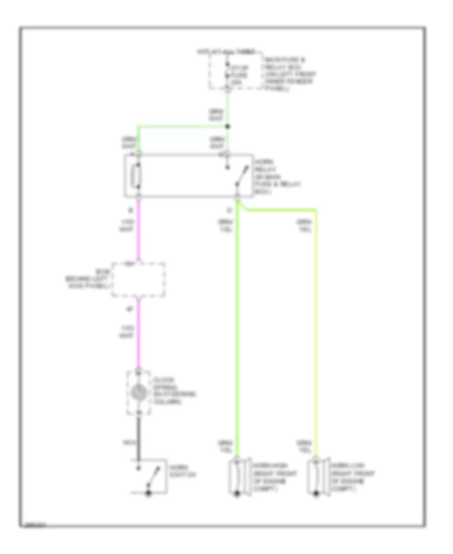
Horn Wiring Diagram for Mazda 6 i Grand Touring 2008
List of elements for Horn Wiring Diagram for Mazda 6 i Grand Touring 2008:
- (right front of engine compt)
- Bcm (behind left kick panel)
- Clock spring (in steering column)
- Horn high
- Horn low
- Horn relay (in main fuse & relay box)
- Horn switch
- Hot at all times
- Main fuse & relay box (on left front inner fender panel)
- Nca
- Stop fuse 20a
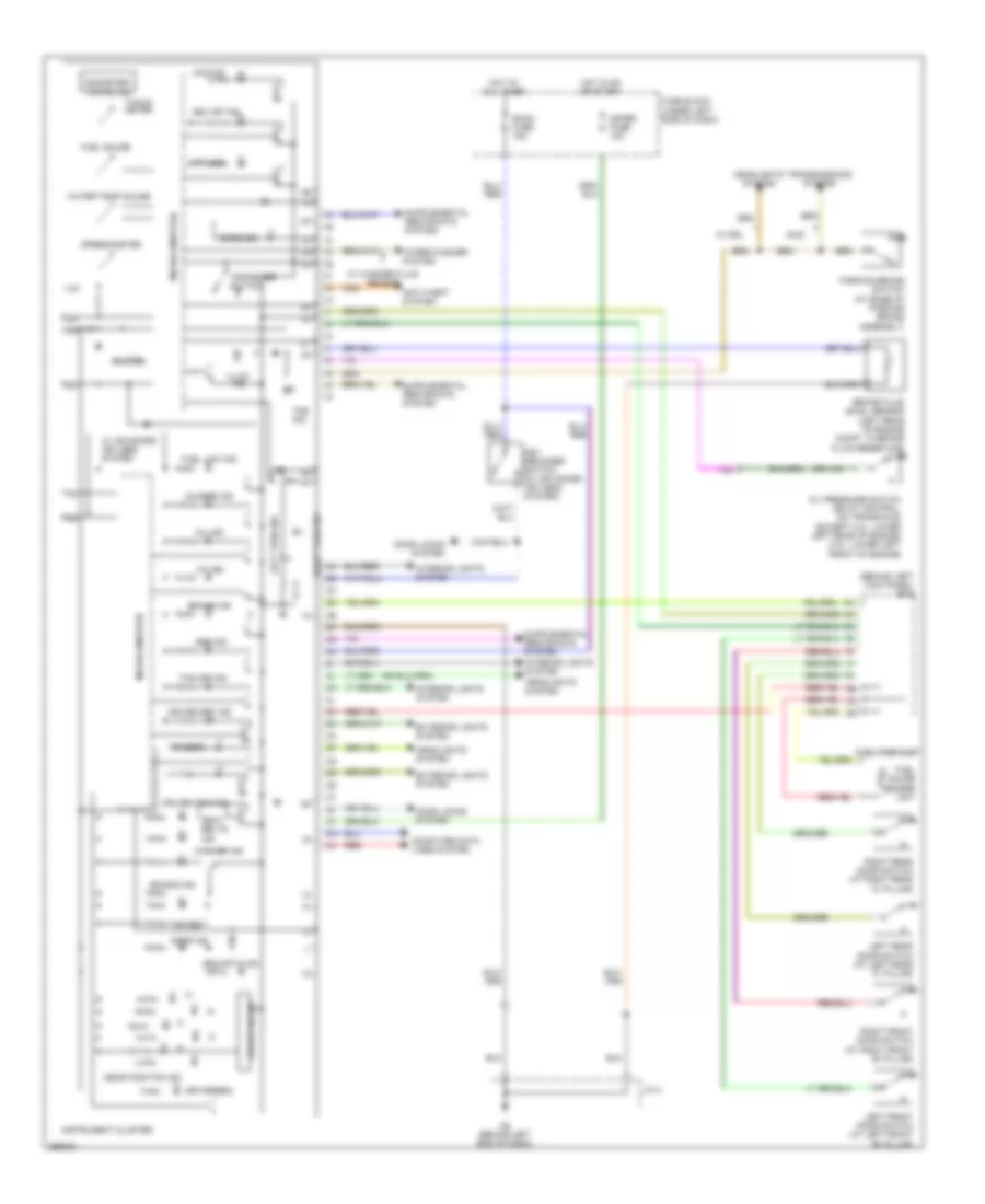
INSTRUMENT CLUSTER
Instrument Cluster Wiring Diagram for Mazda 6 i Grand Touring 2008
List of elements for Instrument Cluster Wiring Diagram for Mazda 6 i Grand Touring 2008:
- (behind left kick panel) bcm
- 4wd ind
- A/t ind
- Abs ind
- Air bag ind
- Anti-theft system
- Awd
- Beam ind
- Brake fluid level sensor (left rear of engine compt, in brake fluid reservoir)
- Brake ind
- Buzzer
- Charge ind
- Computer data lines system
- Cruise main ind
- Cruise set ind
- Door ind
- Door locks system
- Drive circuit
- Dsc ind
- Dsc off ind
- Exterior lights system
- Fuel gauge
- Fuel gauge sender unit
- Fuel low ind
- Fuel pump unit
- Fuse block (under left side of dash)
- G2 (behind left end of dash)
- Gear position ind
- Headlights system
- Hot at all times
- Hot in on or start
- Illum ind
- Instrument cluster
- Interior lights system
- J/c 2
- Key reminder switch (w/ advanced keyless system)
- Key(green)
- Key(red)
- Left front door switch (at left front "b" pillar)
- Left rear door switch (at left rear "c" pillar)
- Left turn ind
- Meter fuse 15a
- Microcomputer
- Mil ind
- Odometer/ tripmeter
- Oil ind
- Oil pressure switch (ec-at control: on transaxle) (except 3.0l: lower left rear of engine) (3.0l: lower left front of engine)
- Parking brake switch (at base of parking brake assembly)
- Red
- Right front door switch (at right front "b" pillar)
- Right rear door switch (at right rear "c" pillar)
- Right turn ind
- Room fuse 15a
- Seat belts ind
- Security ind
- Speedometer
- Tacho meter
- Tcs off ind
- Tns ind
- Transmissions system
- Tripmeter switch
- W/ advanced keyless system
- W/ drl
- W/ washer fluid sensor
- Washer ind
- Water temp gauge
- Wiper/washer system
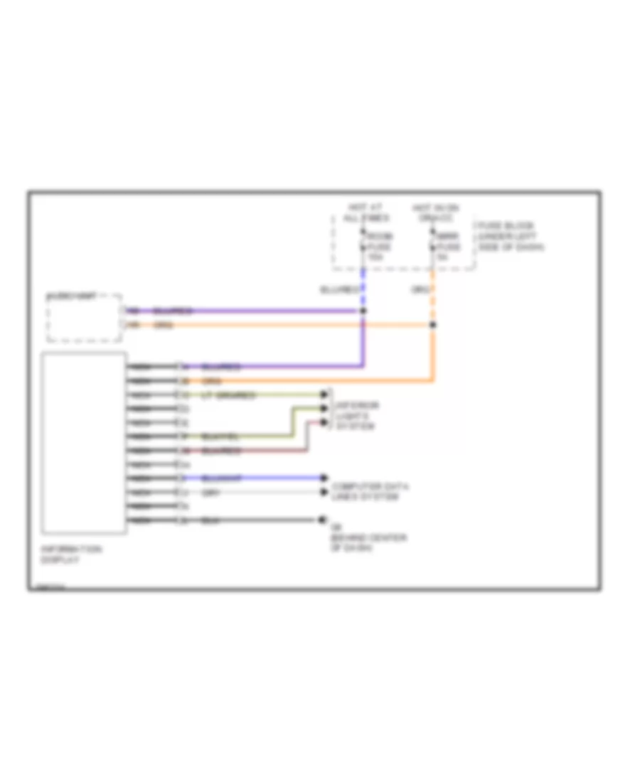
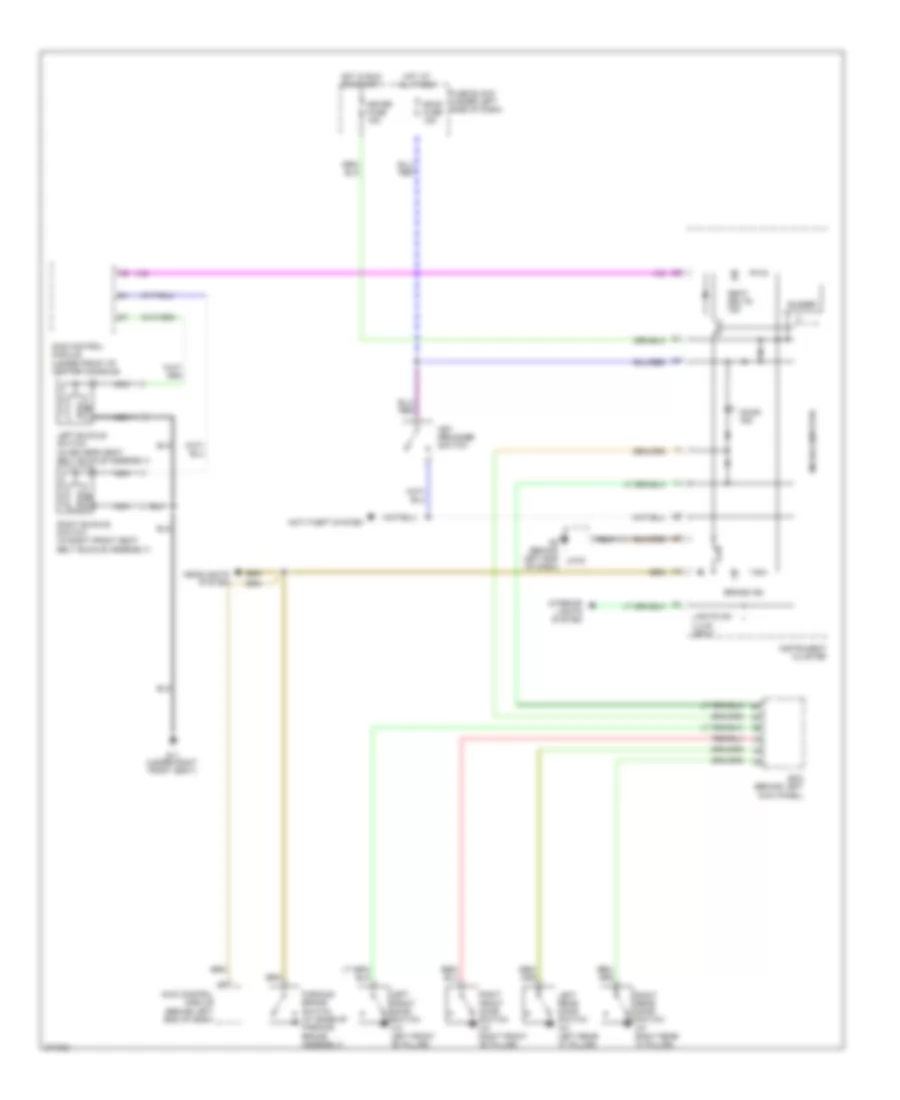
Multi-Information System Wiring Diagram for Mazda 6 i Grand Touring 2008
List of elements for Multi-Information System Wiring Diagram for Mazda 6 i Grand Touring 2008:
- Audio unit
- Computer data lines system
- Fuse block (under left side of dash)
- G8 (behind center of dash)
- Hot at all times
- Hot in on or acc
- Information display
- Interior lights system
- Mirr fuse 5a
- Nca
- Room fuse 15a
INTERIOR LIGHTS
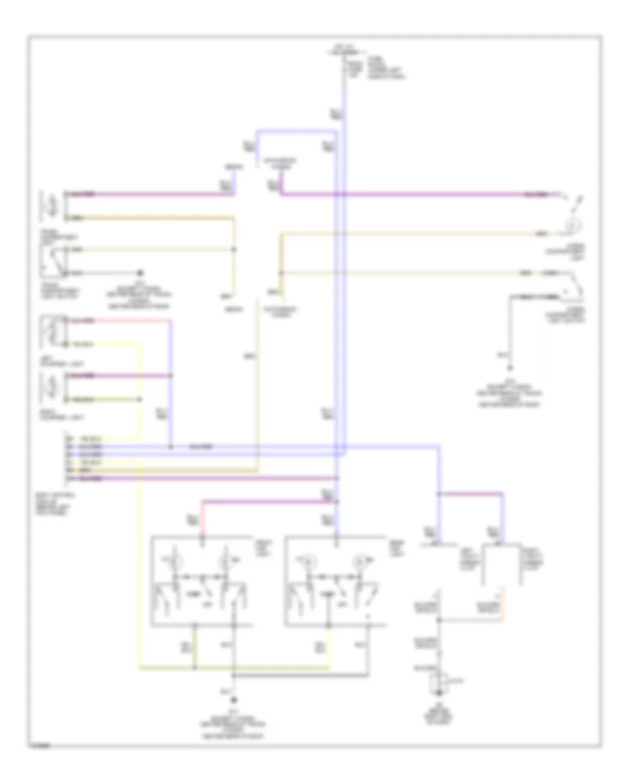
Courtesy Lamps Wiring Diagram for Mazda 6 i Grand Touring 2008
List of elements for Courtesy Lamps Wiring Diagram for Mazda 6 i Grand Touring 2008:
- (except wagon: center rear of trunk) (wagon: center rear of roof)
- Body control module (behind left kick panel)
- Cargo compartment light
- Cargo compartment light switch
- Door
- Front map light
- Fuse block (under left side of dash)
- G14
- G14 (except wagon: center rear of trunk) (wagon: center rear of roof)
- G9 (behind right end of dash)
- Hatchback/ wagon
- Hot at all times
- J/c 03
- Left courtesy light
- Left vanity mirror illum
- Nca
- Off
- Rear map light
- Right courtesy light
- Right vanity mirror illum
- Room fuse 15a
- Sedan
- Trunk compartment light
- Trunk compartment light switch
Instrument Illumination Wiring Diagram for Mazda 6 i Grand Touring 2008
List of elements for Instrument Illumination Wiring Diagram for Mazda 6 i Grand Touring 2008:
- (behind left end of dash) g2
- 0922-202
- 0922-205
- Audio control switch illum (w/ audio control switch)
- Audio unit illum
- Auto light-off control module (behind left side of dash)
- Body computer module (behind left kick panel)
- Climate control unit (w/ automatic a/c)
- Clock spring (in steering column)
- Cruise control switch illum
- Fuse block (under left side of dash)
- G6 (behind left side of dash)
- G7 (behind left side of dash)
- Glove compartment light
- Head
- Headlight switch
- Hot at all times
- Hot in acc or run
- Hot in on or start
- Ignition key illum (w/o keyless system)
- Illum
- Illum fuse 10a
- Illumination 2f
- Information display
- Instrument cluster
- J/c 02
- Lcd unit (w/ navigation)
- Left seat warmer switch (w/ seat warmer)
- Main fuse & relay box (on left front inner fender panel)
- Main fuse 120a
- Meter acc fuse 5a
- Meter fuse 15a
- Microcomputer
- Nca
- Off
- Oscillator
- Panel light control switch
- Right seat warmer switch (w/ seat warmer)
- Room fuse 15a
- Selector illum (w/ a/t)
- Steering lock unit (w/ keyless system) (in steering column)
- Steering wheel
- Tcs off switch/ dsc off switch (w/ abs)
- Tns
- Tns relay
NAVIGATION
Navigation Wiring Diagram for Mazda 6 i Grand Touring 2008
List of elements for Navigation Wiring Diagram for Mazda 6 i Grand Touring 2008:
- (behind center of dash) g8
- (or red)
- (w/ bose audio)
- (w/ standard audio)
- Bcm (behind left kick panel)
- Car-navigation unit (sedan: center front of luggage compt) (hatchback: under front passenger's seat)
- Cradle (under center console)
- Fuse block (under left side of dash)
- G8 (behind center of dash)
- Hot at all times
- Hot in on or acc
- Interior lights system
- Lcd unit
- Microphone (if equipped) (front center of roof)
- Mirr fuse 5a
- Pnk
- Red
- Room fuse 15a
- Sound
- Sound systems
- Systems
- W/ microphone
- W/o microphone
- Wiper/ washer system
POWER DISTRIBUTION
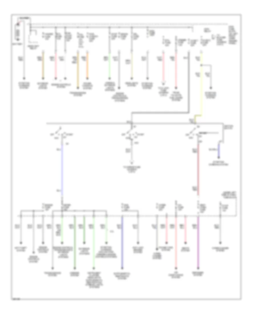
Power Distribution Wiring Diagram (1 of 2) for Mazda 6 i Grand Touring 2008
List of elements for Power Distribution Wiring Diagram (1 of 2) for Mazda 6 i Grand Touring 2008:
- (under left side of dash) fuse block
- 3.0l
- A/c fuse 10a
- Acc
- Air conditioning system
- Anti-lock brakes system
- Anti-theft system
- Battery
- Btn fuse 40a
- Defogger system
- Drl fuse 20a
- Eng+b fuse 7.5a
- Engine controls & transmissions systems
- Engine controls system
- Engine controls, transmissions & exterior lights systems
- Engine fuse 15a
- Etc fuse 7.5a
- Exterior lights system
- Exterior lights systems
- Fuel pump fuse 15a
- Hazard fuse 10a
- Headlight relay
- Headlights system
- Horns & exterior lights systems
- Ig key1 fuse 30a
- Ig key2 fuse 40a
- Ig1
- Ig2
- Ignition switch
- Main fuse 120a
- Main fuse block (on left front inner fender panel)
- Main relay
- Meter fuse 15a
- Mirrors system
- Off
- Opener fuse 7.5a
- Power tops system
- Power windows system
- Pwr window fuse 30a
- R wip fuse 10a
- Sas fuse 10a
- Seat warm fuse 15a
- Seats system
- Start
- Starting/ charging system
- Starting/ charging, cooling fans, mirrors & engine controls systems
- Stop fuse 20a
- Tcm fuse 10a (3.0l) 15a (2.3l)
- To blower fuse (diagram 2 of 2)
- To d lock fuse (diagram 2 of 2)
- To mirror fuse (diagram 2 of 2)
- Transmissions system
- Trunk, tailgate, fuel doors system
- Wiper fuse 20a
- Wiper/ washer system
- Wiper/washer system
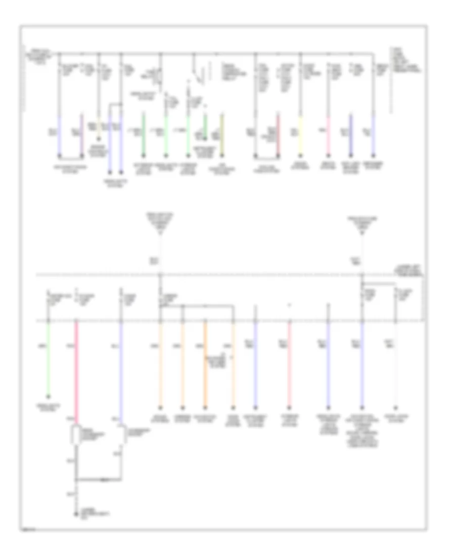
Power Distribution Wiring Diagram (2 of 2) for Mazda 6 i Grand Touring 2008
List of elements for Power Distribution Wiring Diagram (2 of 2) for Mazda 6 i Grand Touring 2008:
- (under driver's seat) g10
- (under left side of dash) fuse block
- Abs fuse 60a
- Accessory socket
- Ad fan fuse (2.3l) fan 2 fuse (3.0l) 30a
- Air conditioning
- Air conditioning system
- Anti-lock brakes system
- Audio fuse (w/ bose) 15a
- Blower fuse 40a
- Cigar fuse 15a
- Cooling fans system
- D lock fuse 30a
- Defog fuse 40a
- Defogger system
- Door locks system
- Engine controls system
- Exterior lights system
- Fan fuse (2.3l) fan 1 fuse (3.0l) 30a
- Fog fuse 15a
- From btn fuse (diagram 1 of 2)
- From ig key2 fuse a (diagram 1 of 2)
- From ignition switch acc (diagram 1 of 2)
- Headlights system
- Headlights, interior lights, warning systems
- Ig1 fuse (3.0l) 15a
- Illumi fuse 10a
- Instrument cluster system
- Interior lights system
- Mag fuse 10a
- Main fuse block (on left front inner fender panel)
- Meter acc fuse 5a
- Mirror fuse 5a
- Mirrors system
- Navigation system
- Navigation, air conditioning, interior lights, sound, mirrors, door locks, computer data lines systems
- Pnk
- Pwr seat fuse 30a
- R cigar fuse 15a
- Rear accessory socket
- Rear window defroster relay
- Room fuse 15a
- Seats system
- Sound systems
- System
- Tail fuse 10a
- Tns relay
- W/ advanced keyless system
POWER DOOR LOCKS
Door Lock Wiring Diagram for Mazda 6 i Grand Touring 2008
List of elements for Door Lock Wiring Diagram for Mazda 6 i Grand Touring 2008:
- (at rear of right front door)
- (at rear of right rear door)
- 5-door/wagon
- Bcm (behind left kick panel)
- D lock fuse 30a
- Door ind
- Fuse block (under left side of dash)
- G1 (left side of engine compt)
- G14 (center rear of trunk)
- G9 (behind right end of dash)
- Hood switch (front right center of engine compt)
- Hot at all times
- Instrument cluster
- Jc-01
- Jc-03
- Keyless control module (w/ advanced keyless system) (behind right end of dash)
- Left door lock switch
- Left front door lock link switch/ left door key cylinder switch/ left front door lock actuator (left front door lock actuator: at rear of left front door)
- Left front door switch (at left "b" pillar)
- Left rear door lock actuator (at rear of left rear door)
- Left rear door lock link switch (in left rear door)
- Left rear door switch (at left "c" pillar)
- Liftgate lock actuator (lower left side of liftgate)
- Right door lock switch
- Right front door lock actuator
- Right front door lock link switch (in right front door)
- Right front door switch (at right "b" pillar)
- Right rear door lock actuator
- Right rear door lock link switch (in right rear door)
- Right rear door switch (at right "c" pillar)
- Room fuse 15a
- Sport sedan
- Trunk key cylinder switch (sport sedan)
- Trunk lid opener (center rear of trunk lid)
- Unlk
Keyless Entry Wiring Diagram for Mazda 6 i Grand Touring 2008
List of elements for Keyless Entry Wiring Diagram for Mazda 6 i Grand Touring 2008:
- 2aa 2aa
- 2ab
- 2ac
- 2ad
- 2y 2y
- 3aa
- Anti-theft system
- Bcm (behind left kick panel)
- Brake switch
- Center incar keyless antenna (under center console)
- Computer data lines system
- Engine fuse 15a
- Front incar keyless antenna (under front of center console)
- Fuse block (under left side of dash)
- G14 (except wagon: center rear of trunk) (wagon: center rear of roof)
- G7 (behind left side of dash)
- G9 (behind right end of dash)
- Hot at all times
- Hot in acc or on
- Hot in on or start
- Instrument cluster
- Interior lights & mirrors systems
- Jc-03
- Key ind (green)
- Key ind (red)
- Key reminder switch (w/o advanced keyless system)
- Keyless buzzer (in driver's door)
- Keyless control module (w/ advanced keyless system) (behind right end of dash)
- Keyless receiver (behind center of dash)
- Keyless receiver (w/o advanced keyless system) (behind center of dash)
- Left front outcar keyless antenna (in driver's door)
- Left front request switch
- Left key cylinder switch/ left door lock link switch
- Microcomputer
- Mirr fuse 5a
- Nca
- Pnk
- Rear incar keyless antenna (center front of trunk lid)
- Rear outcar keyless antenna (behind center of rear bumper)
- Red
- Right front outcar keyless antenna (in right front door)
- Right front request switch
- Room fuse 15a
- Selector indicator drive circuit
- Shift interlock system
- Steering lock unit (in steering column)
- Trunk request switch
- W/o advanced keyless system
POWER MIRRORS
Power Mirrors Wiring Diagram for Mazda 6 i Grand Touring 2008
List of elements for Power Mirrors Wiring Diagram for Mazda 6 i Grand Touring 2008:
- Auto dimming mirror
- Bcm (behind left kick panel)
- Defogger system
- Door locks system
- Down
- Fuse block (under left side of dash)
- G9 (behind right end of dash)
- Heated outer mirror
- Hot at all times
- Hot in acc or run
- Hot in run or start
- Jc g-03
- Left
- Left power outer mirror (at mirror)
- Left/right
- Meter fuse 15a
- Mirror fuse 5a
- Nca
- Power outer mirror switch
- Power windows system
- Right
- Right power outer mirror (at mirror)
- Room fuse 15a
- Transmissions & exterior lights systems
- Up/down
POWER SEATS
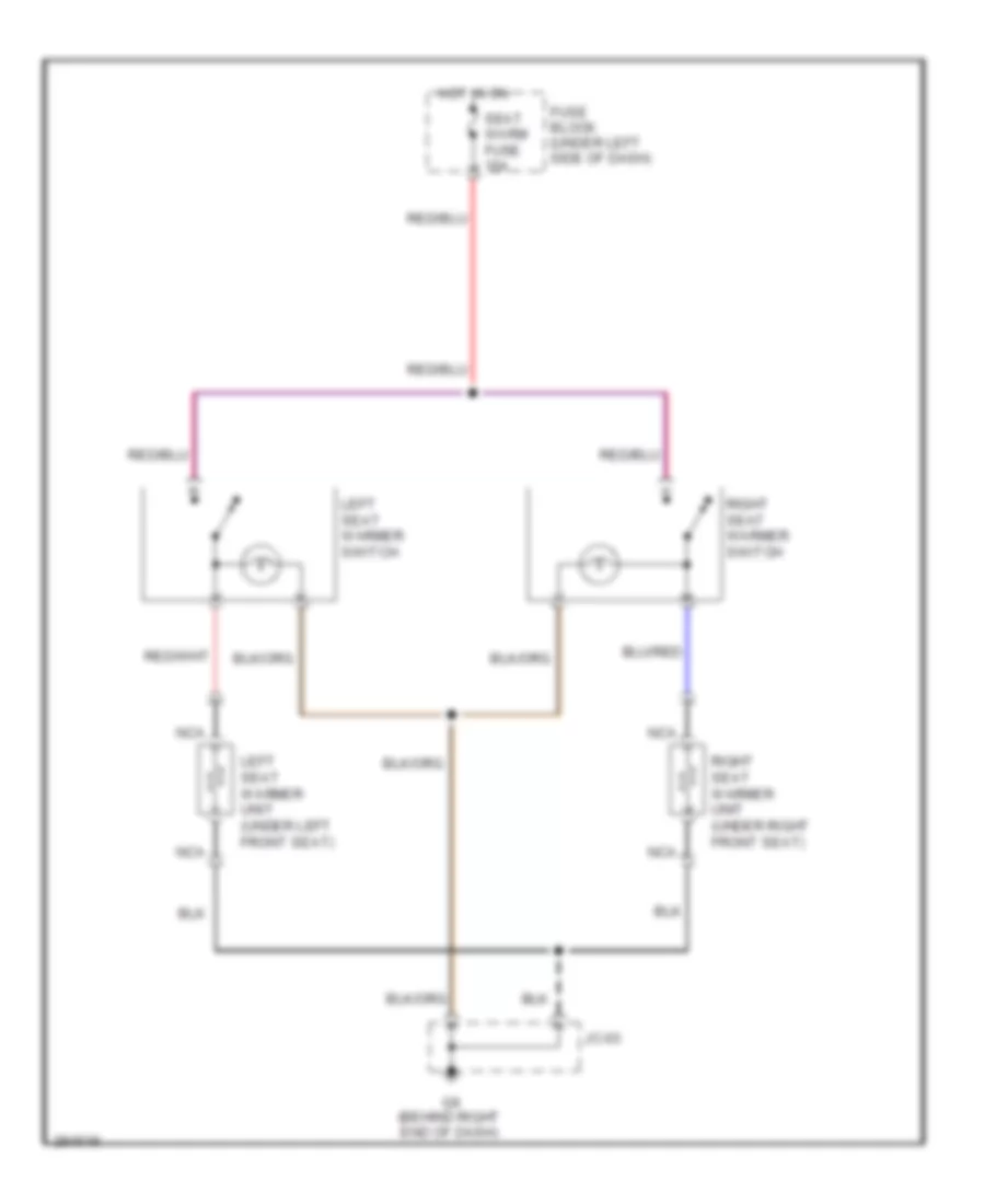
Heated Seats Wiring Diagram for Mazda 6 i Grand Touring 2008
List of elements for Heated Seats Wiring Diagram for Mazda 6 i Grand Touring 2008:
- Fuse block (under left side of dash)
- G9 (behind right end of dash)
- Hot in on
- Jc-03
- Left seat warmer switch
- Left seat warmer unit (under left front seat)
- Nca
- Right seat warmer switch
- Right seat warmer unit (under right front seat)
- Seat warm fuse 15a
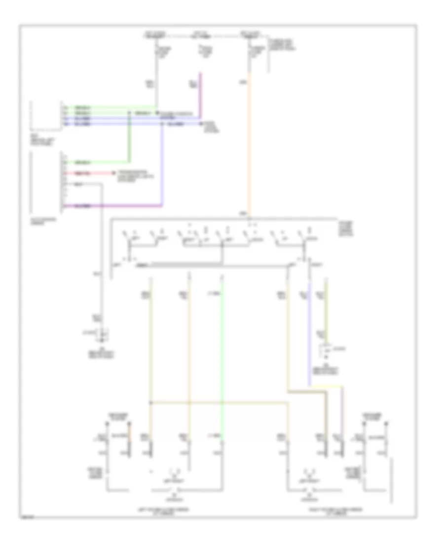
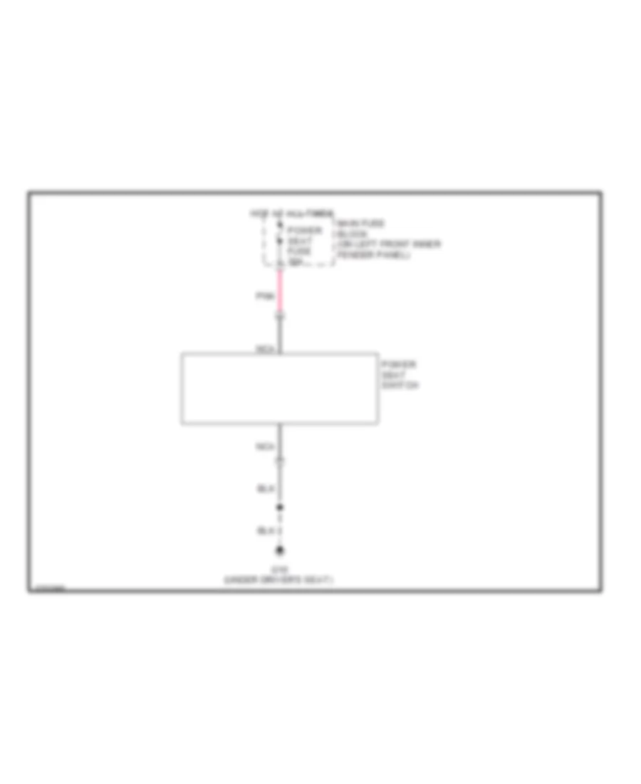
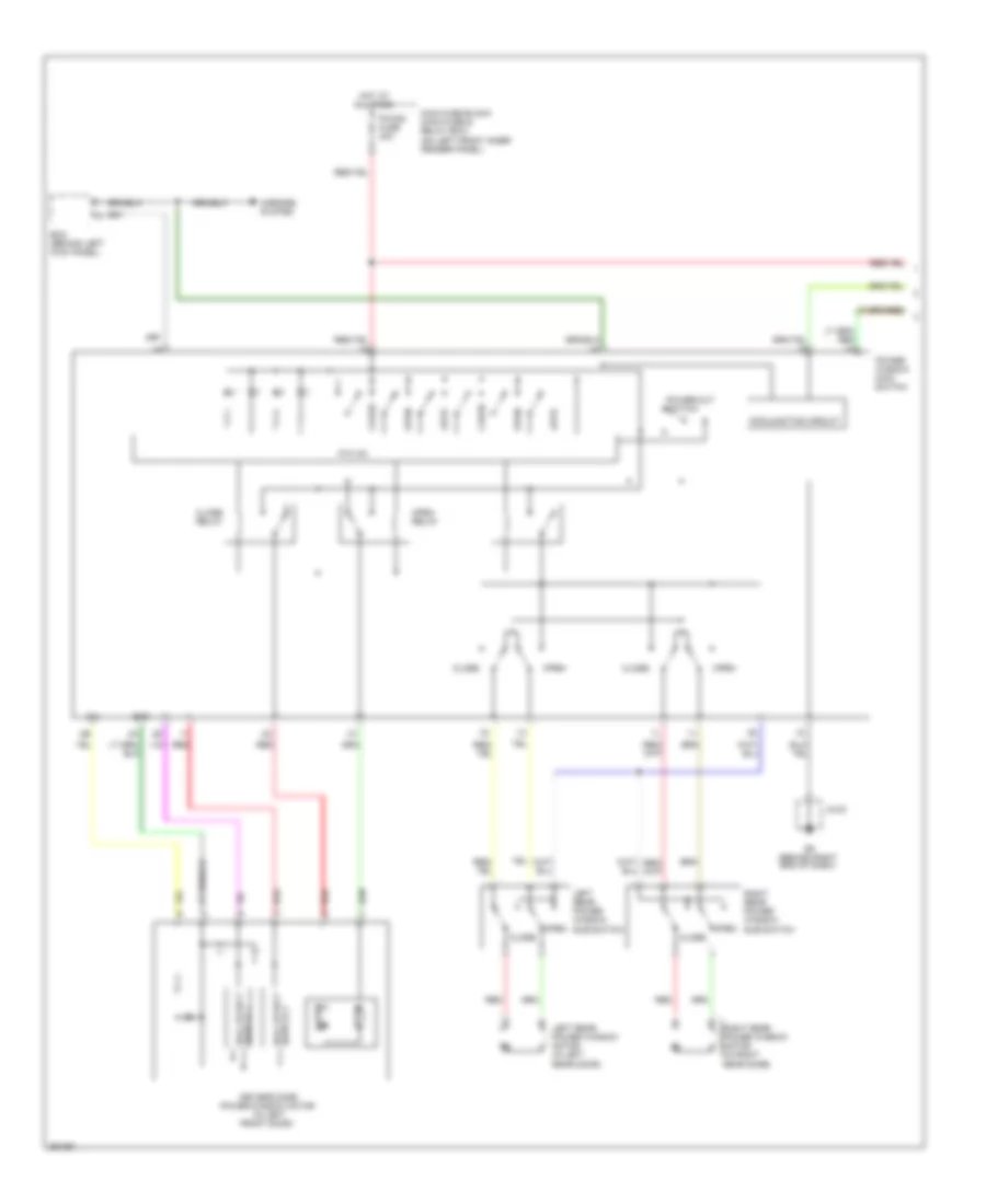
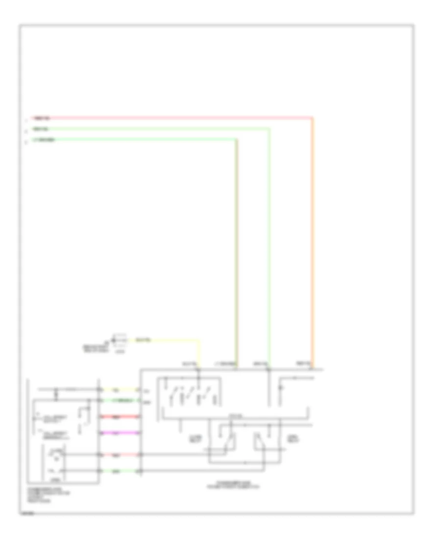
Power Seat Wiring Diagram for Mazda 6 i Grand Touring 2008
List of elements for Power Seat Wiring Diagram for Mazda 6 i Grand Touring 2008:
- G10 (under driver's seat)
- Hot at all times
- Main fuse block (on left front inner fender panel)
- Nca
- Pnk
- Power seat fuse 30a
- Power seat switch
POWER TOP/SUNROOF
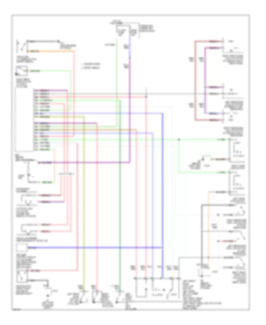
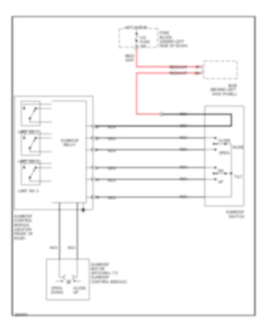
Power Top/Sunroof Wiring Diagram for Mazda 6 i Grand Touring 2008
List of elements for Power Top/Sunroof Wiring Diagram for Mazda 6 i Grand Touring 2008:
- A/c fuse 10a
- Bcm (behind left kick panel)
- Close
- Close, up
- Fuse block (under left side of dash)
- Hot in run
- Limit sw 1
- Limit sw 2
- Limit sw 3
- Nca
- Open
- Open, down
- Slide
- Sunroof control module (center front of roof)
- Sunroof motor (integral to sunroof control module)
- Sunroof relay
- Sunroof switch
- Tilt
POWER WINDOWS
Power Windows Wiring Diagram (1 of 2) for Mazda 6 i Grand Touring 2008
List of elements for Power Windows Wiring Diagram (1 of 2) for Mazda 6 i Grand Touring 2008:
- 12v
- Auto
- Bcm (behind left kick panel)
- Close
- Close relay
- Conjunction circuit
- Driver's side power window motor (in left front door)
- G9 (behind right end of dash)
- Gnd
- Hall effect switch 1
- Hall effect switch 2
- Hot at all times
- Jc-03
- Left rear power window motor (in left rear door)
- Left rear power window sub switch
- Main fuse block (main fuse & relay box) (on left front inner fender panel)
- Mirrors system
- Open
- Open relay
- P/w cm
- Power window main switch
- Power-cut switch
- Pwind fuse 30a
- Red
- Right rear power window motor (in right rear door)
- Right rear power window sub switch
Power Windows Wiring Diagram (2 of 2) for Mazda 6 i Grand Touring 2008
List of elements for Power Windows Wiring Diagram (2 of 2) for Mazda 6 i Grand Touring 2008:
- 12v
- Auto
- Close
- Close relay
- G9 (behind right end of dash)
- Gnd
- Hall effect switch 1
- Hall effect switch 2
- Jc-03
- Open
- Open relay
- P/w cm
- Passenger's side power window motor (in right front door)
- Passenger's side power window subswitch
- Red
RADIO
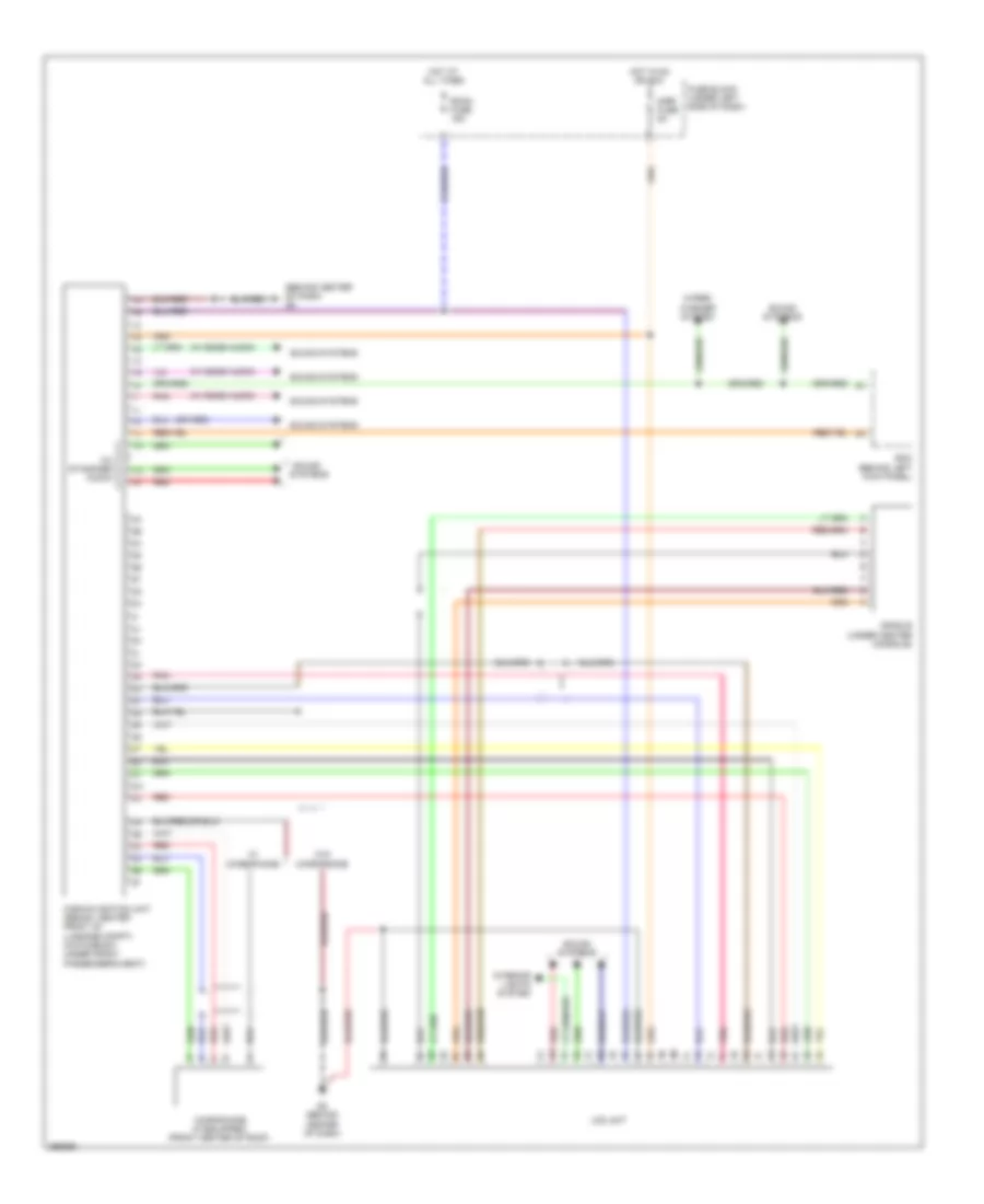
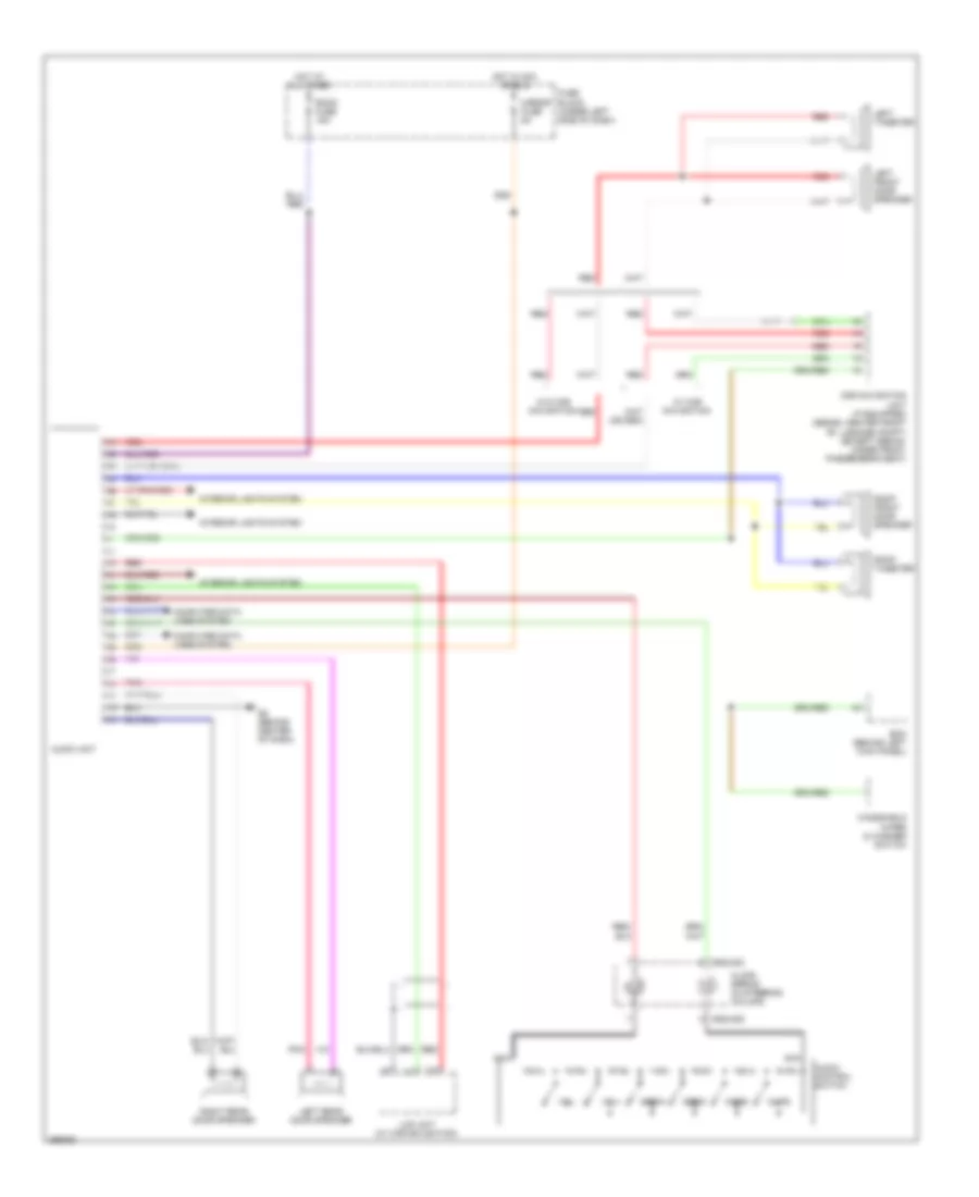
Radio Wiring Diagram, with Base Radio for Mazda 6 i Grand Touring 2008
List of elements for Radio Wiring Diagram, with Base Radio for Mazda 6 i Grand Touring 2008:
- 0922-202
- 0922-205
- Audio control switch
- Audio unit
- Bcm (behind left kick panel)
- Car navigation unit (if equipped) (sedan: center front of luggage compt) (except sedan: under front passenger's seat)
- Clock spring (in steering column)
- Computer data lines system
- Fuse block (under left side of dash)
- G8 (behind center of dash)
- Hot at all times
- Hot in acc or run
- Interior lights system
- Lcd unit (w/ car navigation)
- Left front door speaker
- Left rear door speaker
- Left tweeter
- Mirror fuse 5a
- Mode
- Mute
- Nca
- Pnk
- Red
- Right front door speaker
- Right rear door speaker
- Right tweeter
- Room fuse 15a
- Seek+
- Seek-
- Vol+
- Vol-
- W/ car navigation
- W/o car navigation
- Windshield wiper & washer switch
Radio Wiring Diagram, with Bose for Mazda 6 i Grand Touring 2008
List of elements for Radio Wiring Diagram, with Bose for Mazda 6 i Grand Touring 2008:
- (behind center of dash)
- 0922-202
- 0922-205
- Audio amplifier (under front passenger`s seat)
- Audio control switch
- Audio fuse 15a
- Audio unit
- Back
- Bcm (behind left kick panel)
- Car navigation unit (if equipped) (sedan: center front of luggage compartment) (hatchback: under front passenger's seat)
- Clock spring (in steering column)
- Computer data lines system
- Fuse block (under left side of dash)
- G2 (behind left end of dash)
- G8 (behind center of dash)
- Hatch-
- Hatch- back
- Hot at all times
- Hot in acc or run
- Interior lights system
- J/c c-01
- J/c g-o2
- Lcd unit (w/ navigation)
- Left front door speaker
- Left rear door speaker
- Left tweeter
- Main fuse block (on left front inner fender panel)
- Mirror fuse 5a
- Mode
- Mute
- Nca
- Pnk
- Red
- Right front door speaker
- Right rear door speaker
- Right tweeter
- Room fuse 15a
- Sedan
- Seek+
- Seek-
- Vol+
- Vol-
- W/ navigation
- W/o navigation
- Windshield wiper & washer switch
- Woofer
- Woofer relay
SHIFT INTERLOCK
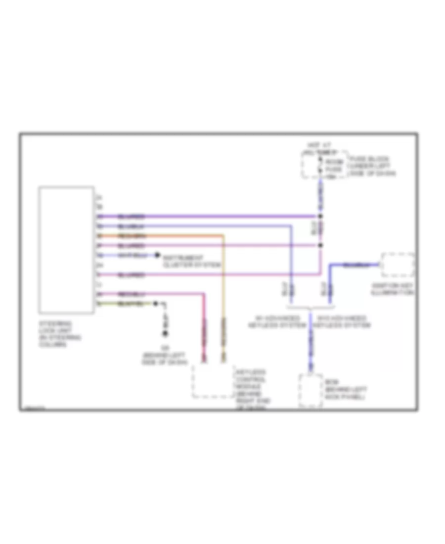
Shift Interlock Wiring Diagram for Mazda 6 i Grand Touring 2008
List of elements for Shift Interlock Wiring Diagram for Mazda 6 i Grand Touring 2008:
- Bcm (behind left kick panel)
- Fuse block (under left side of dash)
- G6 (behind left side of dash)
- Hot at all times
- Ignition key illumination
- Instrument cluster system
- Keyless control module (behind right end of dash)
- Room fuse 15a
- Steering lock unit (in steering column)
- W/ advanced keyless system
- W/o advanced keyless system
STARTING/CHARGING
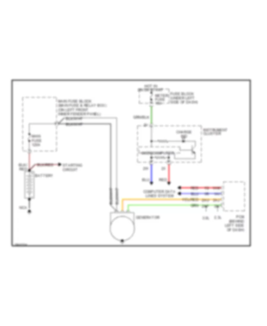
Charging Wiring Diagram for Mazda 6 i Grand Touring 2008
List of elements for Charging Wiring Diagram for Mazda 6 i Grand Touring 2008:
- 1ai
- 1am
- 2.3l
- 2ai
- 2aj
- 2ap
- 2au
- 3.0l
- Battery
- Charge ind
- Computer data lines system
- Fuse block (under left side of dash)
- Generator
- Hot in on or start
- Instrument cluster
- Main fuse 120a
- Main fuse block (main fuse & relay box) (on left front inner fender panel)
- Meter fuse 15a
- Microcomputer
- Nca
- Pcm (behind left side of dash)
- Red
- Starting circuit
2.3L
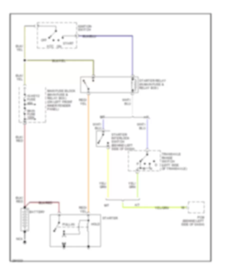
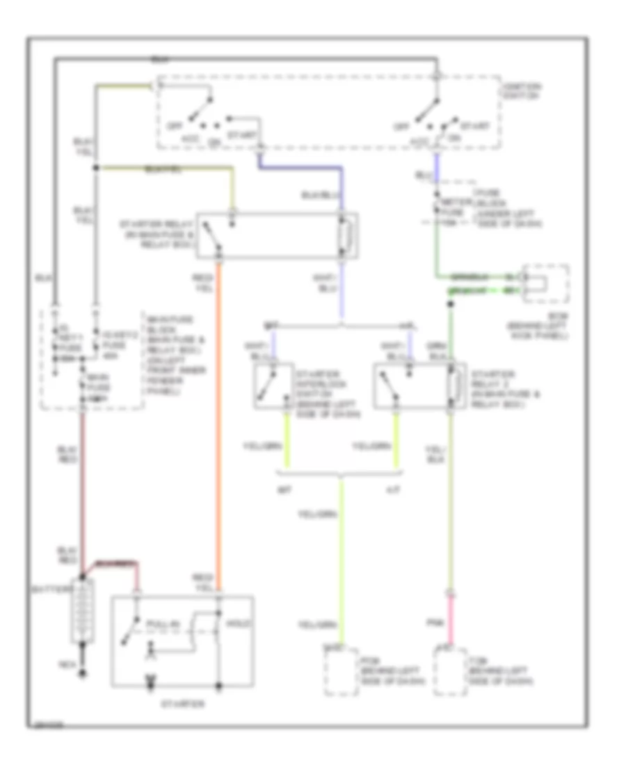
2.3L, Starting Wiring Diagram for Mazda 6 i Grand Touring 2008
List of elements for 2.3L, Starting Wiring Diagram for Mazda 6 i Grand Touring 2008:
- A/t
- Acc
- Battery
- Hold
- Ig key2 fuse 40a
- Ignition switch
- M/t
- Main fuse 120a
- Main fuse block (main fuse & relay box) (on left front inner fender panel)
- Nca
- Off
- Pcm (behind left side of dash)
- Pull-in
- Start
- Starter
- Starter interlock switch (behind left side of dash)
- Starter relay (in main fuse & relay box)
- Transaxle range switch (left side of transaxle)
3.0L
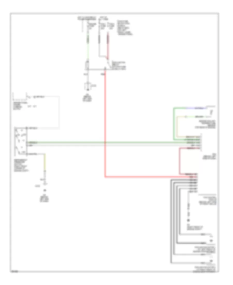
3.0L, Starting Wiring Diagram for Mazda 6 i Grand Touring 2008
List of elements for 3.0L, Starting Wiring Diagram for Mazda 6 i Grand Touring 2008:
- 1ad
- A/t
- Acc
- Battery
- Bcm (behind left kick panel)
- Fuse block (under left side of dash)
- Hold
- Ig key1 fuse 30a
- Ig key2 fuse 40a
- Ignition switch
- M/t
- Main fuse 120a
- Main fuse block (main fuse & relay box) (on left front inner fender panel)
- Meter fuse 15a
- Nca
- Off
- Pcm (behind left side of dash)
- Pnk
- Pull-in
- Start
- Starter
- Starter interlock switch (behind left side of dash)
- Starter relay (in main fuse & relay box)
- Starter relay 2 (in main fuse & relay box)
- Tcm (behind left side of dash)
SUPPLEMENTAL RESTRAINTS
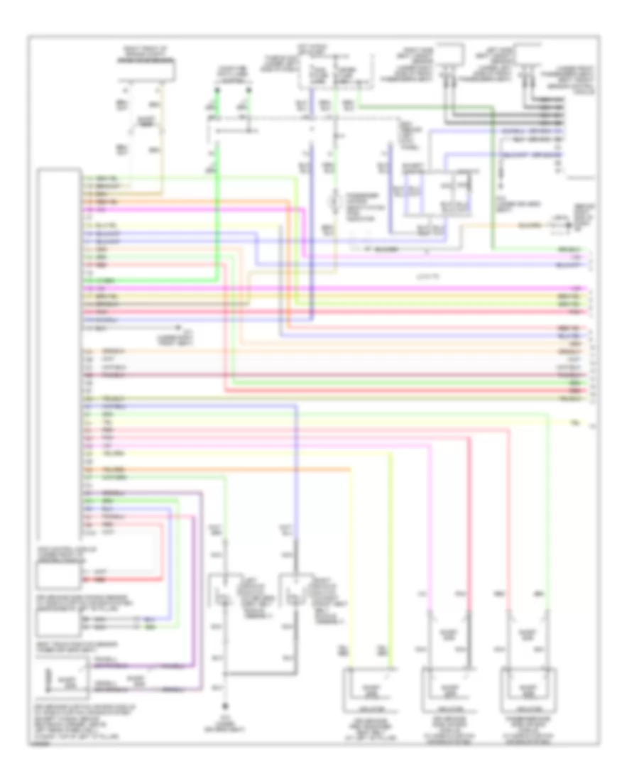
Supplemental Restraints Wiring Diagram (1 of 2) for Mazda 6 i Grand Touring 2008
List of elements for Supplemental Restraints Wiring Diagram (1 of 2) for Mazda 6 i Grand Touring 2008:
- (behind right end of dash) g9
- (or nca)
- (right front of engine compt) crash zone sensor
- (under front passenger's seat) seat weight sensor control module
- 2aa
- A nca
- B nca
- Bcm (behind left kick panel)
- Computer data lines system
- Driver-side curtain air bag module (w/ side & curtain air bag system) (except wagon: behind seatback corner, above left rear wheelwell) (wagon: top of left "d" pillar)
- Driver-side pre-tensioner seat belt (at left "b" pillar)
- Driver-side side air bag module (w/ side & curtain air bag system)
- Driver-side side air bag sensor (w/ side & curtain air bag system) (near base of left "b" pillar)
- Except l3 w/ tc
- Fuse block (under left side of dash)
- G10 (under driver's seat)
- G11 (under right front seat)
- Hall ic
- Hot in run or start
- Inflator
- J/c 3
- L3 w/ tc
- Left buckle switch (in driver's seat belt buckle assembly)
- Left side seat weight sensor (under left side of front passenger's seat)
- Meter fuse 15a
- Nca
- Passenger air bag deactivation (pad) indicator
- Passenger-side side air bag module (w/ side & curtain air bag system)
- Pnk
- Red
- Right buckle switch (in right front seat belt buckle assembly)
- Right side seat weight sensor (under right side of front passenger's seat)
- Sas control module (under front of center console)
- Sas fuse 10a
- Seat track position sensor (under driver's seat)
- Short bar
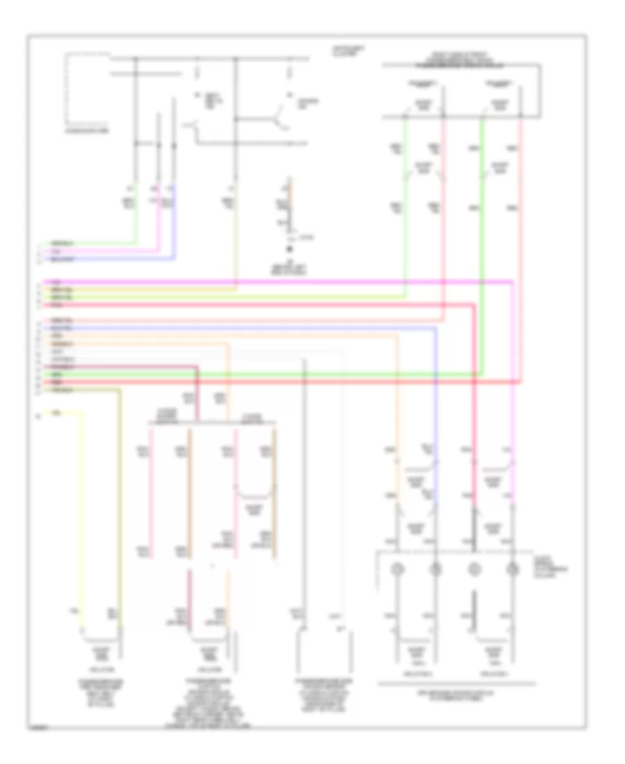
Supplemental Restraints Wiring Diagram (2 of 2) for Mazda 6 i Grand Touring 2008
List of elements for Supplemental Restraints Wiring Diagram (2 of 2) for Mazda 6 i Grand Touring 2008:
- (or red)
- (right side of front passenger's seat back) passenger-side air bag module
- 5 door except l3 w/ tc
- 5 door l3 w/ tc
- Air bag ind
- Clock spring (in steering column)
- Driver-side air bag module (in steering wheel)
- G2 (behind left end of dash)
- Inflator
- Inflator 1
- Inflator 2
- Instrument cluster
- J/c-02
- Microcomputer
- Nca
- Passenger-side curtain air bag module (w/ side & curtain air bag module) (except wagon: behind seatback corner, above right rear wheelwell) (wagon: top of right "d" pillar)
- Passenger-side pre-tensioner seat belt (at right "b" pillar)
- Passenger-side side air bag sensor (w/ side & curtain air bag system) (near base of right "b" pillar)
- Pnk
- Red
- Seat belts ind
- Short bar
TRANSMISSION
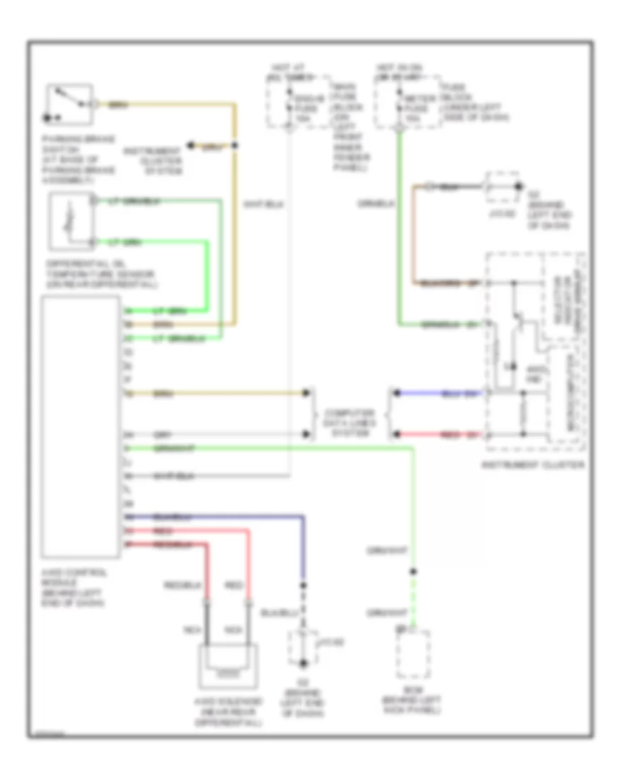
4WD Wiring Diagram for Mazda 6 i Grand Touring 2008
List of elements for 4WD Wiring Diagram for Mazda 6 i Grand Touring 2008:
- 4wd ind
- Awd control module (behind left end of dash)
- Awd solenoid (near rear differential)
- Bcm (behind left kick panel)
- Computer data lines system
- Differential oil temperature sensor (on rear differential)
- Drive circuit indicator selector
- Eng+b fuse 10a
- Fuse block (under left side of dash)
- G2 (behind left end of dash)
- Hot at all times
- Hot in on or start
- Instrument cluster
- Instrument cluster system
- J/c-02
- Main fuse block (on left front inner fender panel)
- Meter fuse 15a
- Microcomputer
- Nca
- Parking brake switch (at base of parking brake assembly)
- Red
2.3L
2.3L, A/T Wiring Diagram for Mazda 6 i Grand Touring 2008
List of elements for 2.3L, A/T Wiring Diagram for Mazda 6 i Grand Touring 2008:
- (behind left end of dash) g2
- (behind left kick panel) bcm
- 0517-106
- 0517-112
- A/t ind
- A/t main relay (in main fuse & relay box)
- Bcm (behind left kick panel)
- Computer data lines system
- Down switch
- Eng+b fuse 7.5a
- Engine controls system
- Exterior lights system
- Fuse block (under left side of dash)
- G2 (behind left end of dash)
- G23 (in transaxle)
- G25 (in transaxle)
- G9 (behind right end of dash)
- Gear position ind
- Hot at all times
- Hot in on or start
- Input/turbine speed sensor (on transaxle)
- Instrument cluster
- Intermediate sensor (on transaxle)
- J/c-02
- J/c-03
- M range switch
- Main fuse block (on left front inner fender panel)
- Meter fuse 15a
- Microcomputer
- Oil pressure switch (on transaxle)
- Pressure control solenoid a
- Pressure control solenoid b
- Primary solenoid valve
- R position
- Red
- Secondary solenoid valve
- Selector indicator drive circuit
- Selector lever component (sport a/t)
- Sensor temperature fluid transaxle
- Shift solenoid a
- Shift solenoid b
- Shift solenoid c
- Shift solenoid d
- Shift solenoid e
- Shift solenoid f
- Tcm fuse 15a
- Transaxle case
- Transaxle control module (tcm) (behind left side of dash)
- Up switch
- Vehicle speed sensor (on transaxle)
- W/o abs
3.0L
3.0L, A/T Wiring Diagram for Mazda 6 i Grand Touring 2008
List of elements for 3.0L, A/T Wiring Diagram for Mazda 6 i Grand Touring 2008:
- (behind left end of dash) g2
- (behind left kick panel) bcm
- A/t ind
- A10
- A11
- A12
- A13
- A14
- A15
- A16
- B10
- B11
- B12
- B13
- B14
- B15
- B16
- B17
- B18
- B19
- B20
- B21
- B22
- Computer data lines system
- Down sw
- Engine controls system
- Exterior lights system
- Fuse block (under left side of dash)
- G9 (behind right end of dash)
- Gear position ind
- Hot at all times
- Hot in run or start
- Input/turbine speed sensor (on transaxle)
- Instrument cluster
- J/c g02
- J/c-03
- Line pressure control solenoid
- M range sw
- Main fuse block (on left front inner fender panel)
- Meter fuse 15a
- Micro- computer
- Nca
- Pnk
- Red
- Selector indicator drive circuit
- Selector lever component (sport a/t)
- Shift solenoid a
- Shift solenoid d
- Shift solenoid e
- Solenoid b shift
- Solenoid c shift
- Solenoid f shift
- Solenoid tcc control
- Solenoid valve (on rear of transaxle)
- Starting/charging system
- Tcm fuse 10a
- Transaxle control module (tcm) (behind left side of dash)
- Transaxle fluid temperature sensor
- Up sw
- Vehicle speed sensor (on transaxle)
TRUNK, TAILGATE, FUEL DOOR
Trunk Release Wiring Diagram for Mazda 6 i Grand Touring 2008
List of elements for Trunk Release Wiring Diagram for Mazda 6 i Grand Touring 2008:
- (behind left kick panel)
- Bcm
- G14 (except wagon: center rear of trunk) (wagon: center rear of roof)
- G6 (behind left side of dash)
- Hot at all times
- Main fuse block (on left front inner fender panel)
- Opener fuse 7.5a
- Trunk lid lock actuator (integral to trunk lock assembly)
- Trunk lid opener relay (in main fuse & relay box)
- Trunk lid opener switch
WARNING SYSTEMS
Warning Systems Wiring Diagram for Mazda 6 i Grand Touring 2008
List of elements for Warning Systems Wiring Diagram for Mazda 6 i Grand Touring 2008:
- Anti-theft system
- Awd control module (behind left end of dash)
- Bcm (behind left kick panel)
- Brake ind
- Buzzer
- Door ind
- Fuse block (under left side of dash)
- G11 (under right front seat)
- G2 (behind left end jc-02
- Hall
- Headlights system
- Hot at all times
- Hot in run or start
- Instrument cluster
- Interior lights system
- Key reminder switch
- Left buckle switch (in driver's seat belt buckle assembly)
- Left front door switch (at left front "b" pillar)
- Left rear door switch (at left rear "c" pillar)
- Lights on/ illum input
- Meter fuse 15a
- Microcomputer
- Nca
- Of dash)
- Parking brake switch (at base of parking brake assembly)
- Right buckle switch (in right front seat belt buckle assembly)
- Right front door switch (at right front "b" pillar)
- Right rear door switch (at right rear "c" pillar)
- Room fuse 15a
- Sas control module (under front of center console)
- Seat belts ind
WIPER/WASHER
Front Wiper/Washer Wiring Diagram for Mazda 6 i Grand Touring 2008
List of elements for Front Wiper/Washer Wiring Diagram for Mazda 6 i Grand Touring 2008:
- (behind right end of dash)
- Autostop switch
- Bcm (behind left kick panel)
- Circuit breaker
- Fuse block (under left side of dash)
- G1 (left side of engine compt)
- G6 (behind left side of dash)
- Hot in on
- Hot in on or start
- Instrument cluster
- Int
- Int volume
- Intermittent wiper relay
- Jc-01
- Jc-09
- Meter fuse 15a
- Off
- Off int
- One touch
- Washer fluid level sensor (if equipped) (right front corner of engine compt, in washer fluid reservoir)
- Washer ind
- Washer switch
- Windshield washer motor (right front corner of engine compt, on washer fluid reservoir)
- Windshield wiper & washer switch
- Windshield wiper motor (left rear of engine compt)
- Wiper fuse 20a
- Wiper switch
Rear Wiper/Washer Wiring Diagram for Mazda 6 i Grand Touring 2008
List of elements for Rear Wiper/Washer Wiring Diagram for Mazda 6 i Grand Touring 2008:
- (left side of liftgate) (2.3l: right rear of engine) (3.0l: right front of engine)
- Autostop switch
- Bcm (behind left kick panel)
- Capacitor
- Fuse block (under left side of dash)
- G7 (behind left side of dash)
- Hot in on
- Pnk
- R wip fuse 10a
- Rear washer motor (right front corner of engine compt, on washer fluid reservoir)
- Rear washer switch
- Rear wiper & washer switch
- Rear wiper int switch
- Rear wiper motor (left side of liftgate)
- Rear wiper switch