AIR CONDITIONING
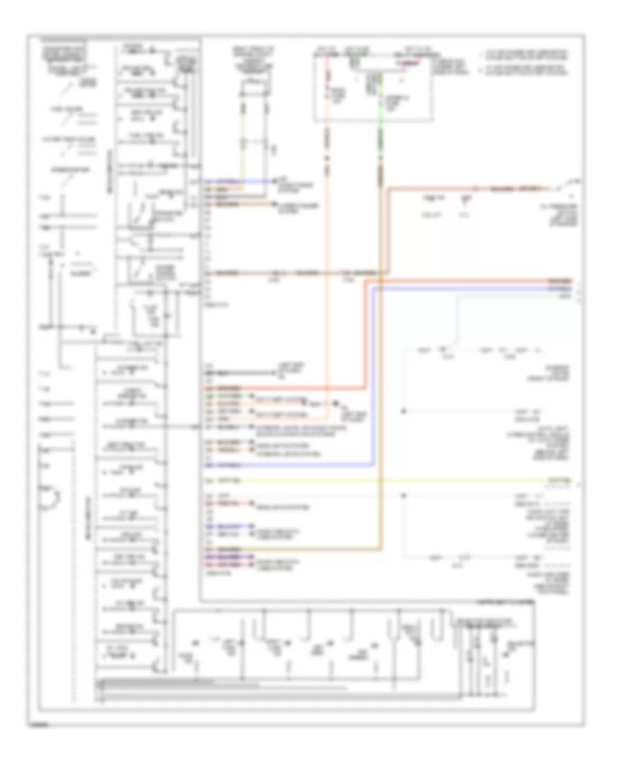
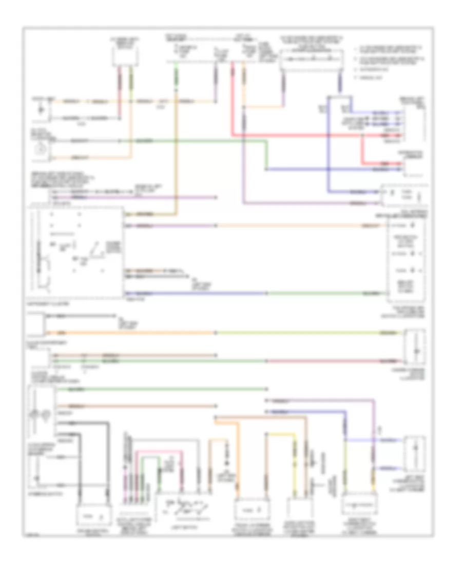
Automatic A/C Wiring Diagram (1 of 3) for Mazda 6 i Grand Touring 2011

List of elements for Automatic A/C Wiring Diagram (1 of 3) for Mazda 6 i Grand Touring 2011:
- (lower right side of dash) g9
- (w/ advanced keyless entry & push button start system) hot w/ ig2 relay energized (w/o advanced keyless entry & push button start system) hot in run
- 0140-101a
- 0140-101b
- 0140-201a
- 0140-201b
- 0140-237
- 0740-201a
- 0740-201b
- 0740-204
- 0922-101b
- 1ae
- 1ah
- 1al
- 1am
- 1ar
- 1at
- 1ay
- 1bj
- 1bl
- 2.5l
- 2ah
- 2av
- 2ay
- 3.7l
- A/c fuse 10a
- C-56
- C-58
- Climate control module (lower center of dash)
- Computer data lines system
- Cylinder head temperature sensor (cht sensor)
- Defogger system
- Engine coolant temperature sensor (left rear of engine compt)
- Fuse block (under left side of dash)
- G8 (left end of dash)
- Hot at all times
- Instrument cluster
- Interior lights system
- Microcomputer
- Passenger compartment temperature sensor (behind left side of dash)
- Pcm (left rear of engine compt)
- Pnk
- Rear vent actuator (w/ rear vent) (front of center console)
- Red
- Refrigerant pressure sensor (right front of engine compt)
- Room fuse 15a
- Solar radiation sensor (top left end of dash)
- Water temperature sensor
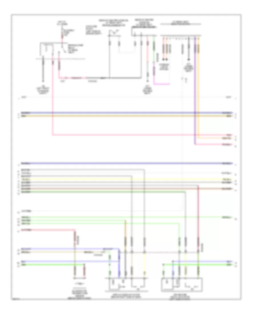
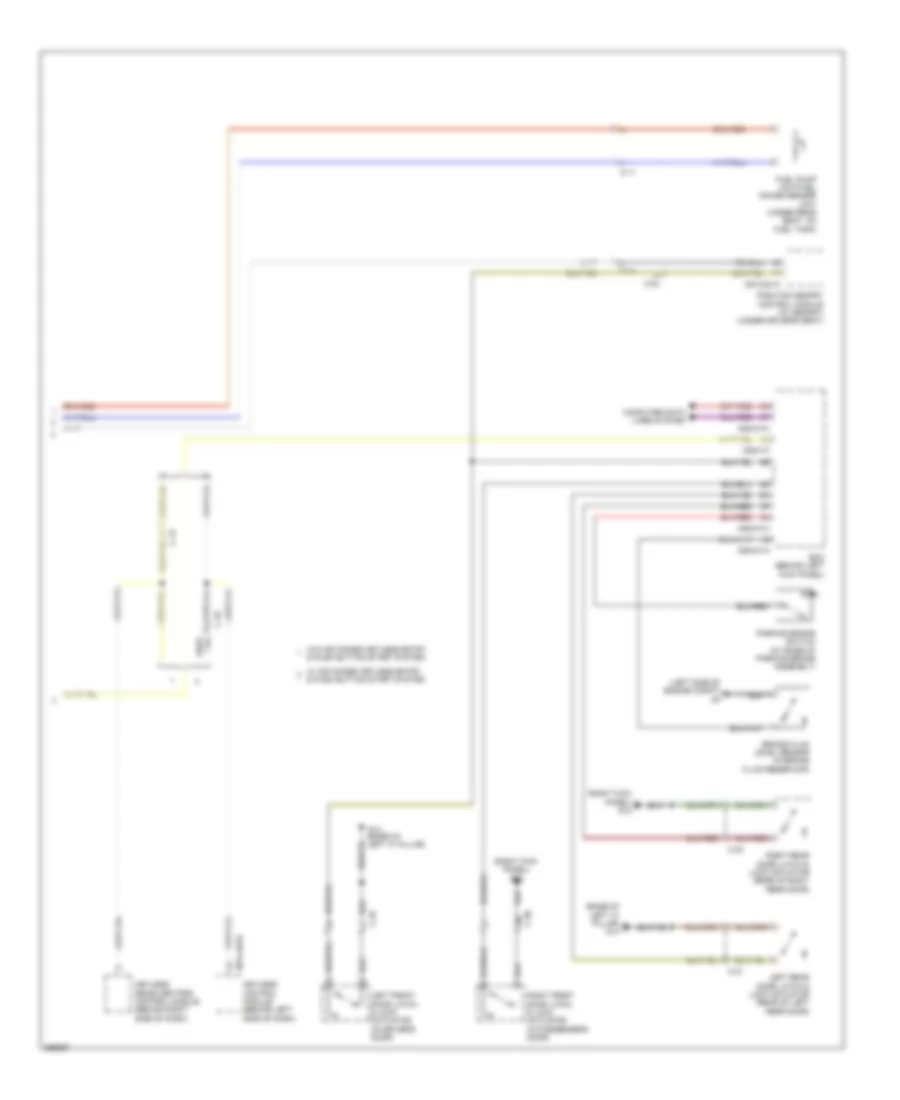
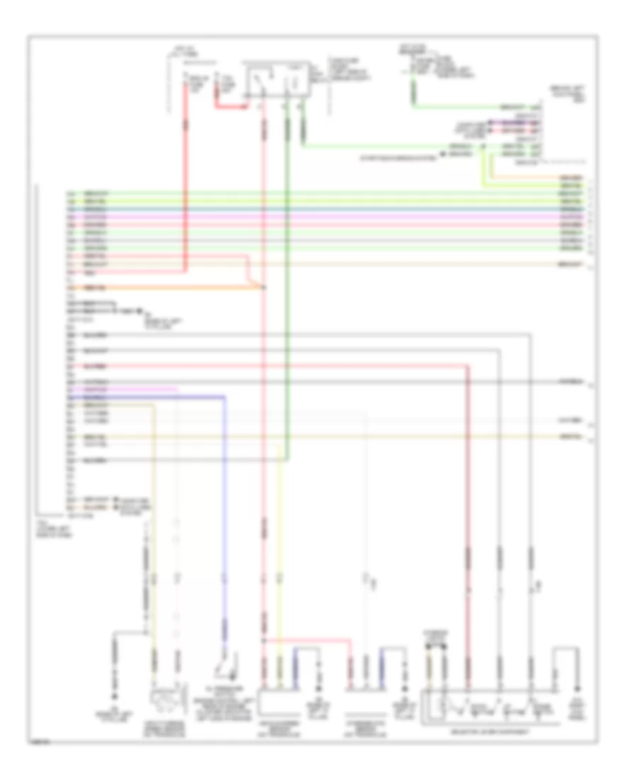
Automatic A/C Wiring Diagram (2 of 3) for Mazda 6 i Grand Touring 2011
List of elements for Automatic A/C Wiring Diagram (2 of 3) for Mazda 6 i Grand Touring 2011:
- (rear of center console) (w/ rear vent) rear blower motor
- (rear of center console) (w/ rear vent) rear power mos fet
- (w/ rear vent) rear fan switch
- 0740-204
- 0740-402
- Airflow mode actuator (behind right side of dash)
- Blower 2 fuse 15a red
- C-07
- C-13
- Cold
- Def
- Driver side air mix actuator (left side of dash)
- Evaporator temperature sensor (behind side of dash)
- G17 (under driver's seat)
- G2 (left front of engine compt)
- Hot
- Hot at all times
- Interior lights system
- Main fuse block (left side of engine compt)
- Pnk
- Rear blower relay (w/ rear vent)
- Red
- Vent
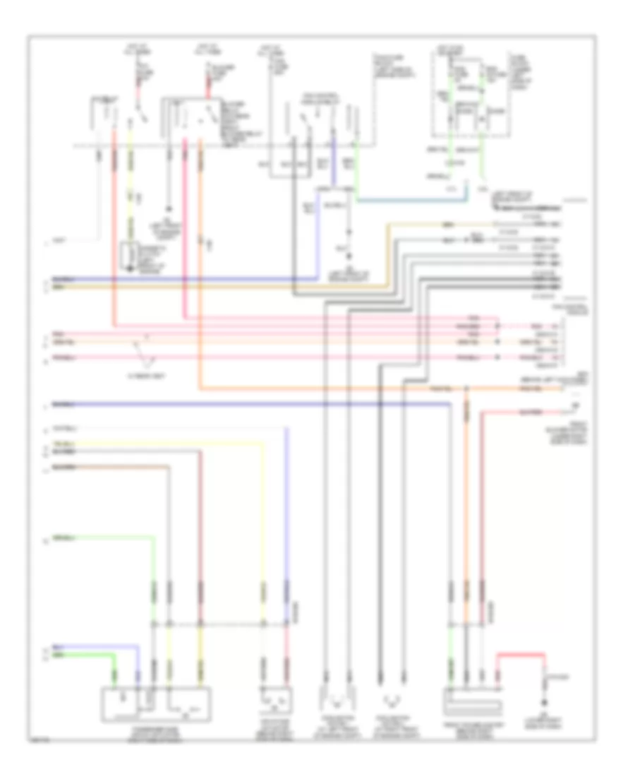
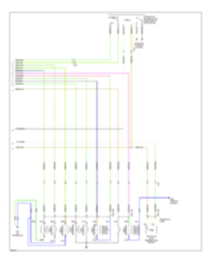
Automatic A/C Wiring Diagram (3 of 3) for Mazda 6 i Grand Touring 2011
List of elements for Automatic A/C Wiring Diagram (3 of 3) for Mazda 6 i Grand Touring 2011:
- (at right front of engine compt)
- 0112-01a
- 0112-01b
- 0112-01c
- 0112-02
- 0112-03
- 0740-203
- 0740-204
- 0940-01a
- 0940-01f
- 0940-01g
- 2.5l
- 2.5l (left front of engine compt) g2
- 3.7l
- A/c fuse 10a red
- A/c relay
- Air intake actuator (behind right side of dash)
- Bcm (behind left kick panel)
- Blower fuse 40a red
- Blower relay (w/o rear vent) front blower relay (w/ rear vent)
- C-02
- C-05
- C-05 y
- Cold
- Cooling fan motor 1 (at left front of engine compt)
- Cooling fan motor 2
- Diode
- Eng ig fuse 15a
- Fan control module
- Fan control module relay
- Fan fuse 60a
- Front blower motor (under right side of dash)
- Front power mos fet (behind right side of dash)
- Fuse block (under left side of dash)
- G2 (left front of engine compt)
- G9 (lower right side of dash)
- Hot
- Hot at all times
- Hot in on or start
- Magnetic clutch (left front of engine)
- Main fuse block (left side of engine compt)
- Nca
- Passenger side air mix actuator (right side of dash)
- Pnk
- Red
- Sas fuse 5a
- W/ rear vent
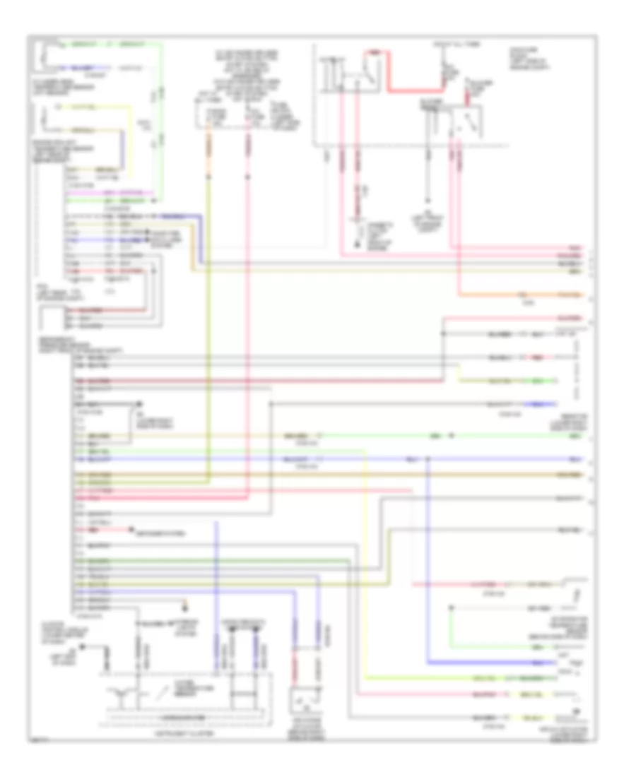
Manual A/C Wiring Diagram (1 of 2) for Mazda 6 i Grand Touring 2011
List of elements for Manual A/C Wiring Diagram (1 of 2) for Mazda 6 i Grand Touring 2011:
- (w/ advanced keyless entry & push button start system) hot w/ ig2 relay energized (w/o advanced keyless entry & push button start system) hot in run
- 0140-101a
- 0140-101b
- 0140-201a
- 0140-201b
- 0140-237
- 0740-101a
- 0740-101b
- 0740-103
- 0740-104
- 0922-101a
- 0922-101b
- 1ae
- 1ah
- 1al
- 1am
- 1ar
- 1at
- 1ay
- 1bj
- 1bl
- 2.5l
- 2ah
- 2av
- 2ay
- 3.7l
- A/c fuse 10a
- A/c fuse 10a red
- A/c relay
- Air intake actuator (behind right side of dash)
- Air mix actuator (lower right side of dash)
- Blower fuse 40a red
- Blower relay
- C-02
- C-05
- C-56
- C-58
- Climate control module (lower center of dash)
- Cold
- Computer data lines system
- Cylinder head temperature sensor (cht sensor)
- Defogger system
- Engine coolant temperature sensor (left rear of engine compt)
- Evaporator temperature sensor (behind side of dash)
- Fuse block (under left side of dash)
- G2 (left front of engine compt)
- G8 (left end of dash)
- G9 (lower right side of dash)
- Hot
- Hot at all times
- Instrument cluster
- Interior lights system
- Magnetic clutch (left front of engine)
- Main fuse block (left side of engine compt)
- Microcomputer
- Pcm (left rear of engine compt)
- Pnk
- Red
- Refrigerant pressure sensor (right front of engine compt)
- Resistor (lower right side of dash)
- Room fuse 15a
- Water temperature sensor
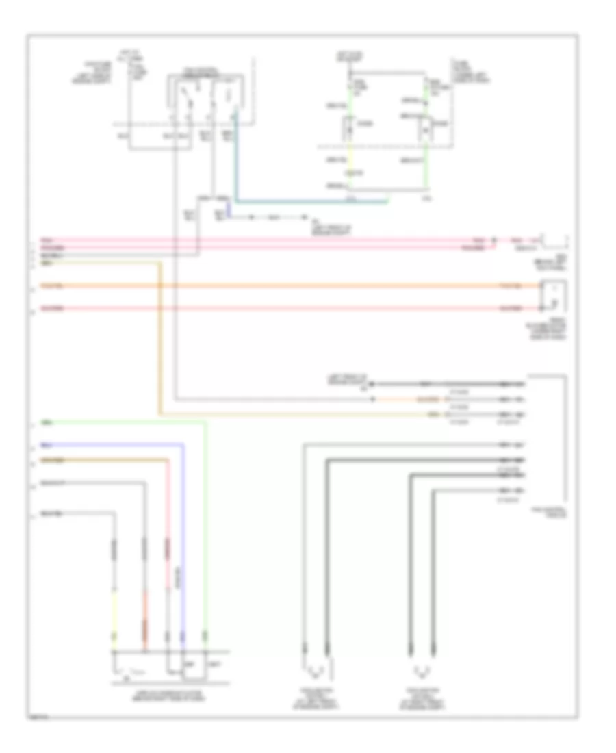
Manual A/C Wiring Diagram (2 of 2) for Mazda 6 i Grand Touring 2011
List of elements for Manual A/C Wiring Diagram (2 of 2) for Mazda 6 i Grand Touring 2011:
- (left front of engine compt) g2
- 0112-01a
- 0112-01b
- 0112-01c
- 0112-02
- 0112-03
- 0740-104
- 0940-01a
- 2.5l
- 3.7l
- Airflow mode actuator (behind right side of dash)
- Bcm (behind left kick panel)
- C-05 y
- Cooling fan motor 1 (at left front of engine compt)
- Cooling fan motor 2 (at right front of engine compt)
- Def
- Diode
- Eng ig fuse 15a
- Fan control module
- Fan control module relay
- Fan fuse 60a
- Front blower motor (under right side of dash)
- Fuse block (under left side of dash)
- G2 (left front of engine compt)
- Hot at all times
- Hot in on or start
- Main fuse block (left side of engine compt)
- Nca
- Pnk
- Sas fuse 5a
- Vent
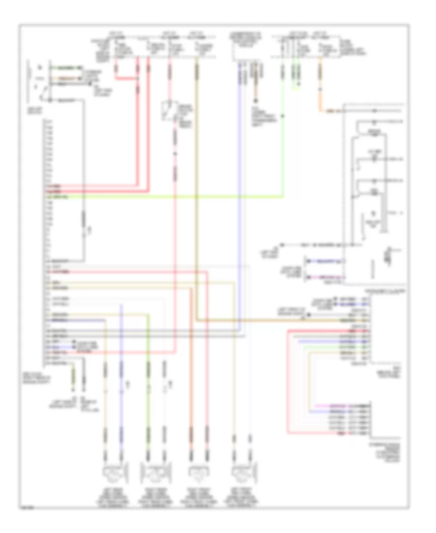
ANTI-LOCK BRAKES
Anti-lock Brakes Wiring Diagram for Mazda 6 i Grand Touring 2011
List of elements for Anti-lock Brakes Wiring Diagram for Mazda 6 i Grand Touring 2011:
- (base of left "a" pillar)
- (left front of engine compt) g2
- (under front of center console) sas control module
- 0810-01b
- 0810-01c
- 0922-101b
- 0940-01b
- 0940-01c
- 0940-01e
- 4w abs ind
- Abs motor fuse 36 60a
- Abs sol fuse 44 30a
- Bcm (behind left kick panel)
- Brake ind
- Brake switch (top of brake pedal)
- C-06
- C-07
- C-65
- Computer data lines system
- Dsc hu/cm (right rear of engine compt)
- Dsc ind
- Dsc off ind
- Dsc off switch
- Fuse block (under left side of dash)
- G16 (under right front passenger's
- G5 g3 (left side of engine compt)
- G8 (left end of dash)
- Hazard fuse 2 10a
- Hot at all times
- Hot in on or start
- Instrument cluster
- Interior lights system
- Left front abs wheel speed sensor (left front wheel hub assembly)
- Left rear abs wheel speed sensor (left rear wheel hub assembly)
- Main fuse block (left side of engine compt)
- Micro- computer
- Nca
- Red
- Right front abs wheel speed sensor (right front wheel hub assembly)
- Right rear abs wheel speed sensor (right rear wheel hub assembly)
- Room fuse 48 15a
- Sas fuse 5a
- Seat)
- Steering angle sensor (if equipped) (in steering column)
- Stop fuse 4 10a
ANTI-THEFT
Forced Entry Wiring Diagram for Mazda 6 i Grand Touring 2011
List of elements for Forced Entry Wiring Diagram for Mazda 6 i Grand Touring 2011:
- (base of left "a" pillar) g14
- (right kick panel) g12
- 0914-401c
- 0940-01a
- 0940-01c
- 0940-01d
- 0940-01f
- 0940-01g
- 0940-01h
- 2h 0922-101b
- Bcm (behind left kick panel)
- Buzzer
- C-29
- C-29 t
- C-30
- C-30 am
- C-31
- C-32
- C-35
- C-62
- Computer data lines system
- D lock fuse 25a
- Door close on
- Door ind
- Fuse block (under left side of dash)
- G1 (right front of engine compt)
- G12 (right kick panel)
- G14 (base of left "a" pillar)
- G18 (front of left rear
- Hood latch switch (right front of engine compt)
- Horns system
- Hot at all times
- Instrument cluster
- Keyless control module (w/ advanced keyless entry) (behind left side of dash)
- Left door lock switch
- Left front door latch & lock actuator (in driver's door)
- Left rear door latch & lock actuator (rear of left rear door)
- Lock
- Memory systems
- Microcomputer
- Right door lock switch
- Right front door latch & lock actuator (in passenger's door)
- Right rear door latch & lock actuator (rear of right rear door)
- Room fuse 15a
- Security ind
- Selector indicator drive circuit
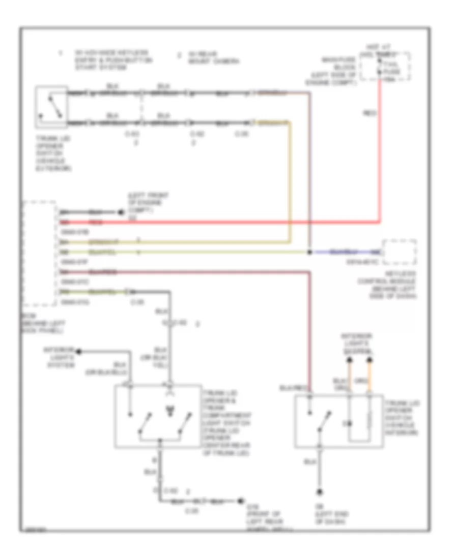
- Trunk lid opener (center rear of trunk lid)
- Un- lock
- W/ rear mount camera
- Wheel well)
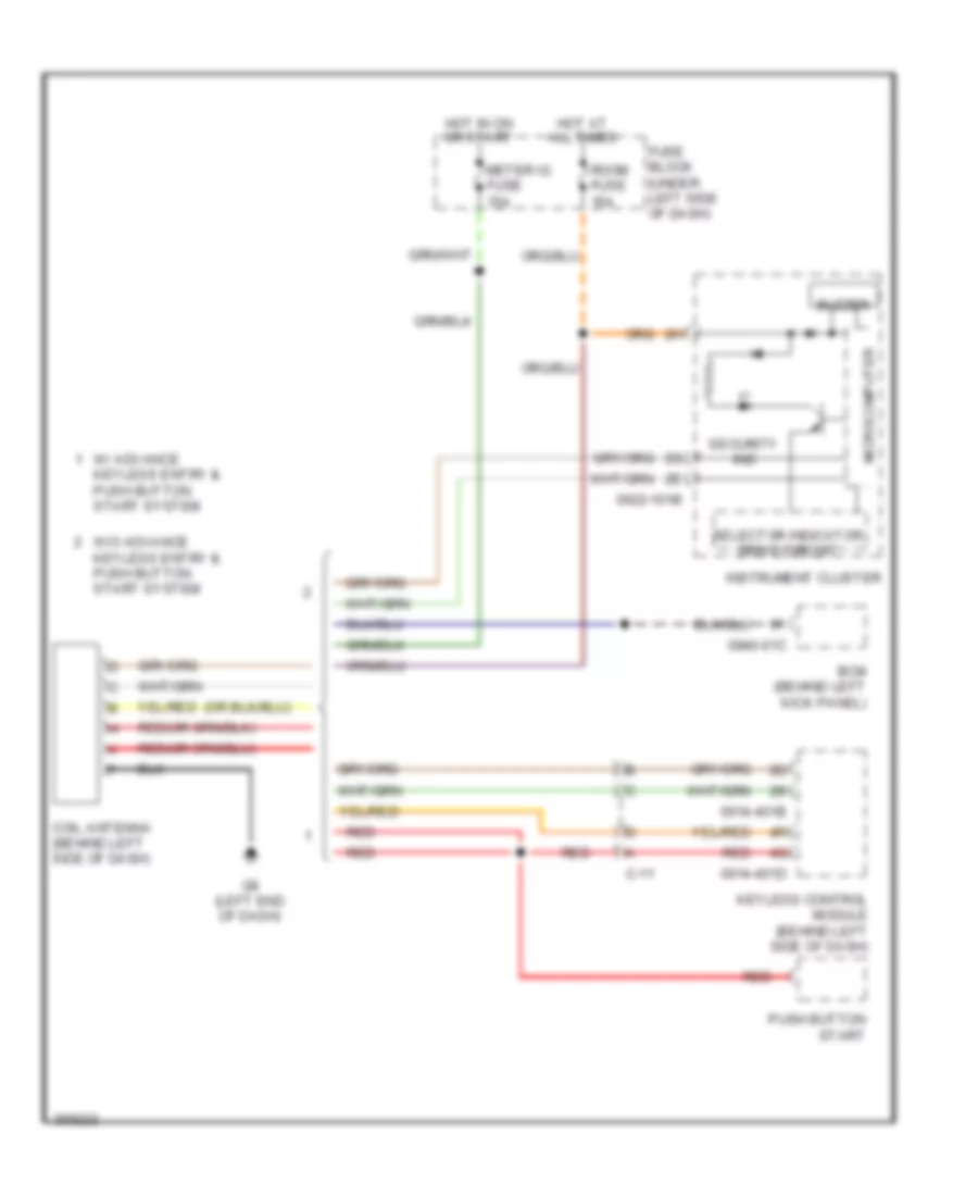
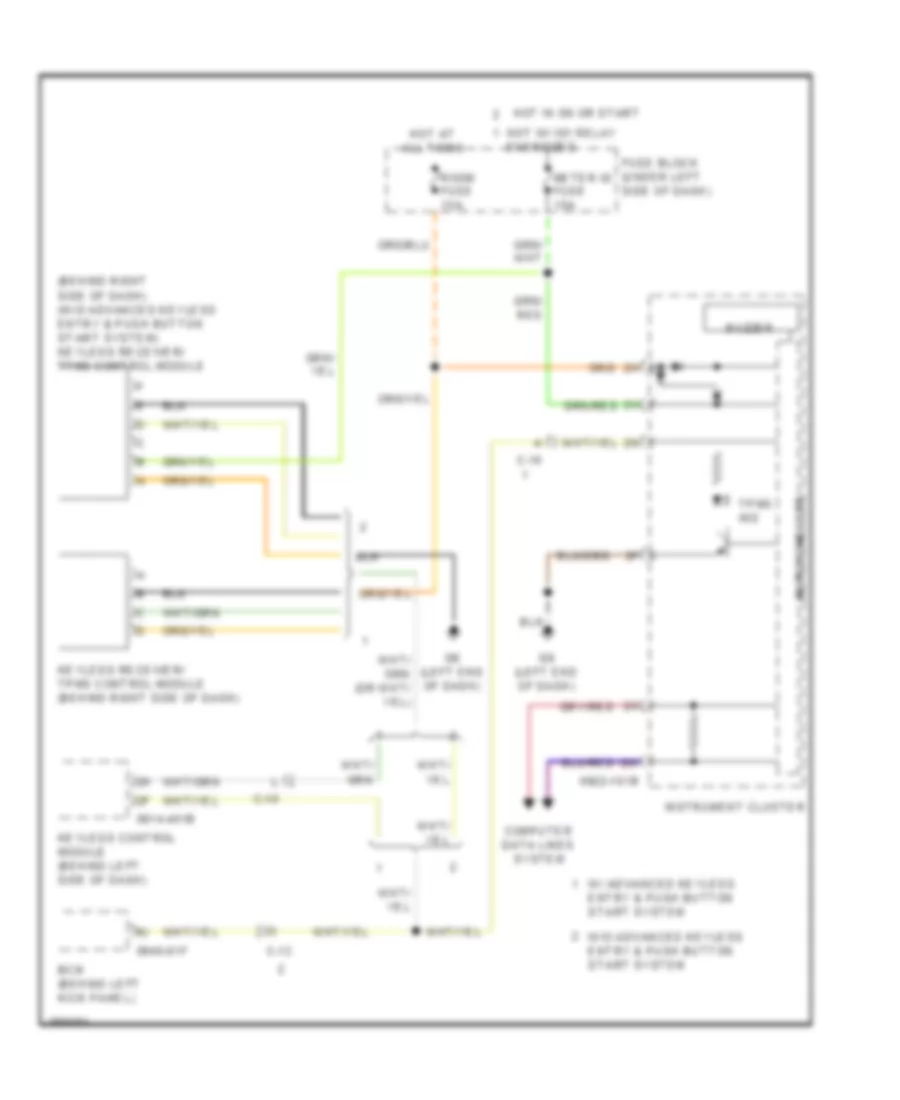
Immobilizer Wiring Diagram for Mazda 6 i Grand Touring 2011
List of elements for Immobilizer Wiring Diagram for Mazda 6 i Grand Touring 2011:
- 0914-401b
- 0914-401d
- 0922-101b
- 0940-01c
- Bcm (behind left kick panel)
- Buzzer
- C-11
- Coil antenna (behind left side of dash)
- Fuse block (under left side of dash)
- G8 (left end of dash)
- Hot at all times
- Hot in on or start
- Instrument cluster
- Keyless control module (behind left side of dash)
- Meter ig fuse 15a
- Microcomputer
- Push button start
- Red
- Room fuse 15a
- Security ind
- Selector indicator drive circuit
- W/ advance keyless entry & push button start system
- W/o advance keyless entry & push button start system
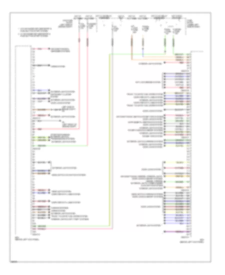
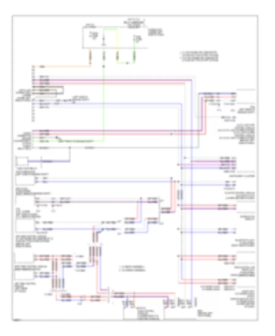
BODY CONTROL MODULES
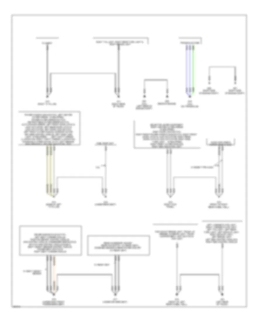
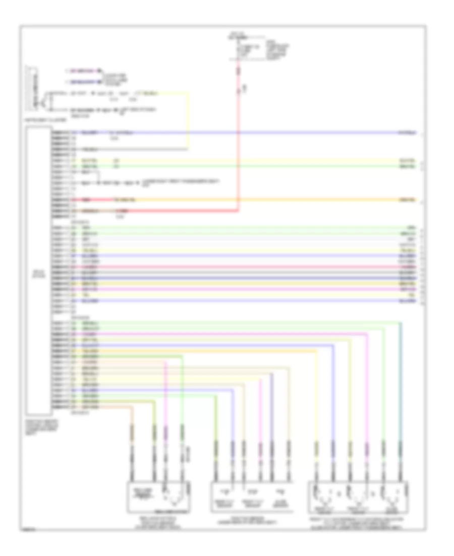
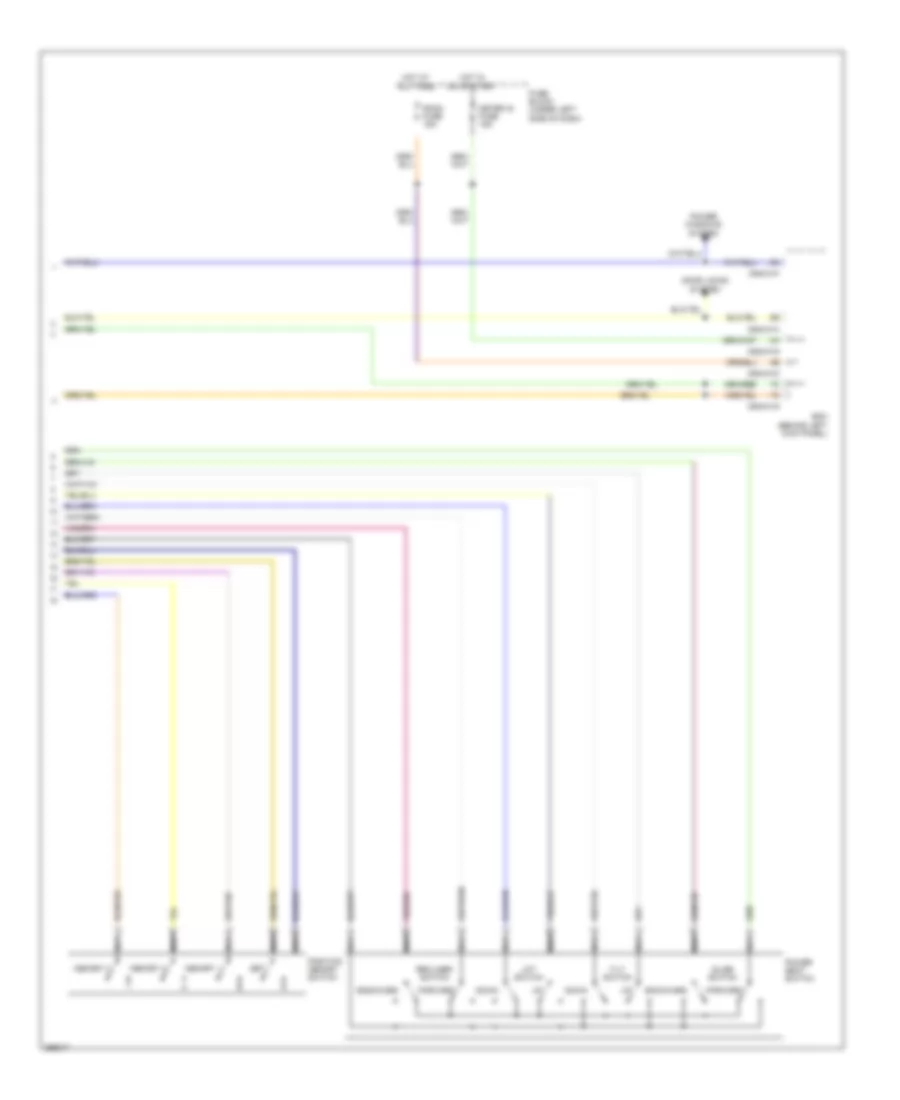
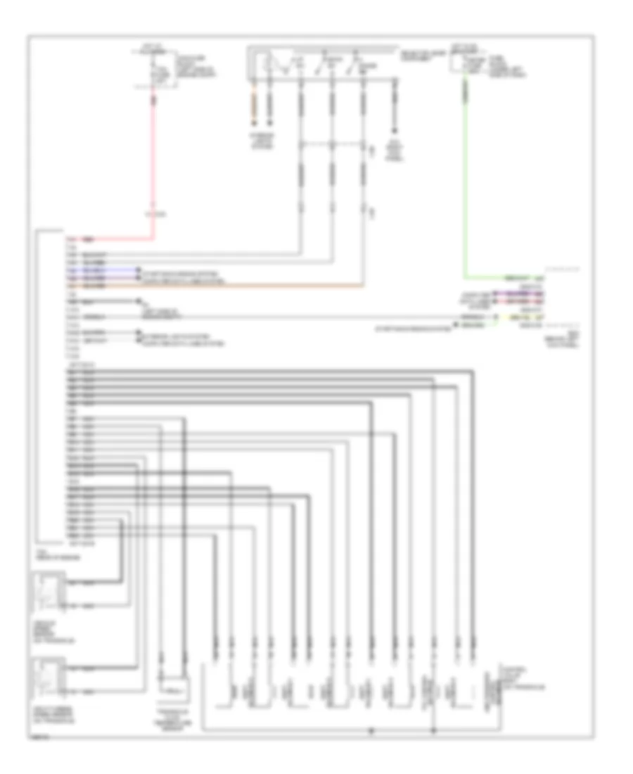
Body Control Modules Wiring Diagram for Mazda 6 i Grand Touring 2011
List of elements for Body Control Modules Wiring Diagram for Mazda 6 i Grand Touring 2011:
- (left front of engine compt)
- (left side of engine compt)
- 0940-01a
- 0940-01b
- 0940-01c
- 0940-01d
- 0940-01e
- 0940-01f
- 0940-01g
- 0940-01h
- 3aa
- 3ab
- 3ac
- 3ad
- A/c fuse 10a
- Air conditioning & defogger systems
- Air conditioning, mirrors, interior lights, door locks & memory systems
- Air conditioning, seats & power tops systems
- Anti-lock brakes system
- Bcm (behind left kick panel)
- Computer data lines system
- D lock fuse 25a
- Door locks & memory systems
- Door locks system
- Exterior lights & mirrors systems
- Exterior lights system
- Fuse block (under left side of dash)
- Hazard fuse 10a
- Headlights & navigation systems
- Headlights & warning systems
- Headlights system
- Horns system
- Hot at all times
- Hot in run
- Hot in run or start
- Hot w/ ig1 relay energized
- Hot w/ ig2 relay energized
- Instrument cluster system
- Interior lights & anti-theft systems
- Interior lights system
- Main fuse block (left side of engine compt)
- Memory, mirrors, exterior lights, wiper/washer, & navigation systems
- Meter fuse 15a
- Pnk
- Power tops system
- Power windows & memory systems
- Red
- Room fuse 15a
- Sas fuse 5a
- Starting/charging, exterior lights & transmissions systems
- Tail fuse 15a
- Trunk, tailgate, fuel doors system
- W/ advanced keyless entry & push button start system
- W/o advanced keyless entry & push button start system
- Warning systems
COMPUTER DATA LINES
Computer Data Lines Wiring Diagram for Mazda 6 i Grand Touring 2011
List of elements for Computer Data Lines Wiring Diagram for Mazda 6 i Grand Touring 2011:
- & push button start system
- (left side of engine compt) g3
- (w/ bose audio)
- (w/o bose audio)
- 0140-101a
- 0140-201a
- 0517-101b
- 0517-201a
- 0740-201a
- 0810-01c
- 0914-401b
- 0918-101b
- 0920-201a
- 0920-301a
- 0920-315b
- 0922-101b
- 0940-01c
- 0940-01f
- 1ah
- 1ai
- 1al
- 1am
- 1b1
- 1bg
- 2.5l
- 3.7l
- A/t
- A14
- Audio unit (w/o bose audio) audio/ car-navigation unit (w/ bose audio) (lower center of dash)
- Auto light-off control module (w/o auto light/wiper system) auto light/wiper control module (w/ auto light/wiper system) (behind left side of dash)
- Bcm (behind left kick panel)
- C-05
- C-06
- C-27
- Check connector (engine compartment) (in main fuse & relay box)
- Climate control module (automatic a/c) (lower center of dash)
- Connector 2 i (under lower left j side of dash)
- Data link h
- Dsc hu/cm (if equipped) (right rear of engine compt)
- Fuel pump relay
- Fuse block (under left side of dash)
- G2 (left front of engine compt)
- Hot at all times
- Hot w/ ig 1
- Information display
- Instrument cluster
- Keyless control module (w/ advanced keyless entry & push button start system) (behind left side of dash)
- Left bsm control module (left rear of trunk)
- M/t
- Main fuse block (left side of engine compt)
- Nca
- Pcm (left rear of engine compt)
- Relay energized hot in run or start
- Right bsm control module (right rear of trunk)
- Room fuse 15a
- Sas control module (under front of center console)
- Sas fuse 5a
- Sirius satellite radio unit (if equipped) (right side of dash)
- Tcm (2.5l: lower left side of dash) (3.7l: rear of engine)
- W/ advanced keyless entry
- W/ bsm
- W/ rear harness 4
- W/o advanced keyless entry
- W/o bsm
- W/o rear harness 4
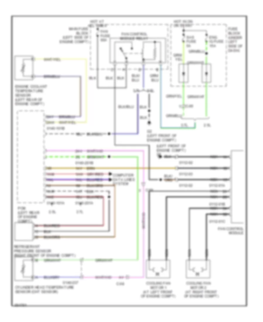
COOLING FAN
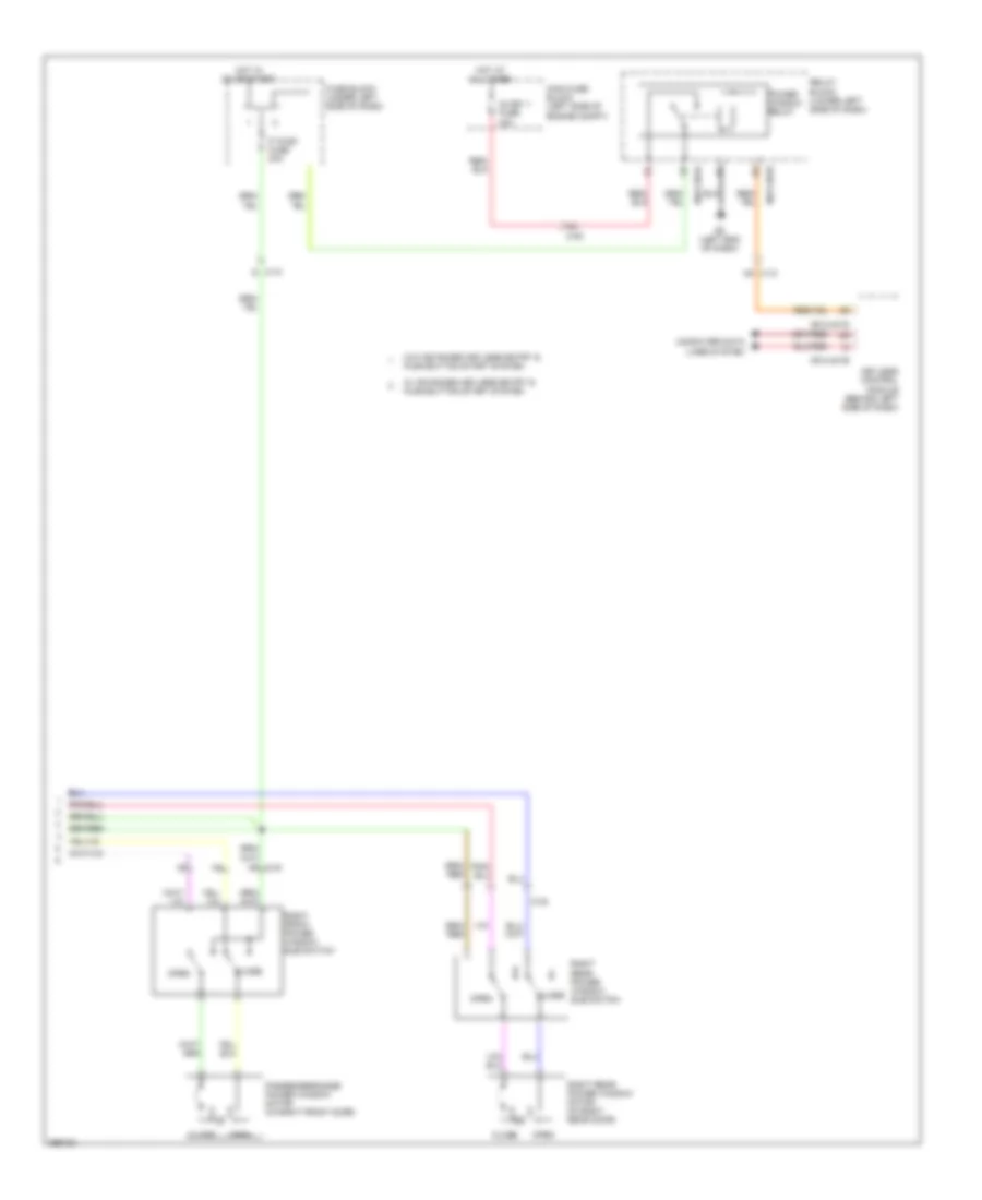
Cooling Fan Wiring Diagram for Mazda 6 i Grand Touring 2011
List of elements for Cooling Fan Wiring Diagram for Mazda 6 i Grand Touring 2011:
- (at right front of engine compt)
- (left front of engine compt) g2
- 0112-01a
- 0112-01b
- 0112-01c
- 0112-02
- 0112-03
- 0140-101a
- 0140-101b
- 0140-201a
- 0140-201b
- 0140-237
- 1ae
- 1ah
- 1al
- 1am
- 1ar
- 1at
- 1ay
- 1bj
- 1bl
- 2.5l
- 2ah
- 2av
- 2ay
- 3.7l
- C-05 y
- C-56 x
- C-58
- Computer data lines system
- Cooling fan motor 1 (at left front of engine compt)
- Cooling fan motor 2
- Cylinder head temperature sensor (cht sensor)
- Eng ig fuse 15a
- Engine coolant temperature sensor (left rear of engine compt)
- Fan control module
- Fan control module relay
- Fan fuse 60a
- Fuse block (under left side of dash)
- G2 (left front of engine compt)
- Hot at all times
- Hot in on or start
- Main fuse block (left side of engine compt)
- Nca
- Pcm (left rear of engine compt)
- Refrigerant pressure sensor (right front of engine compt)
- Sas fuse 5a
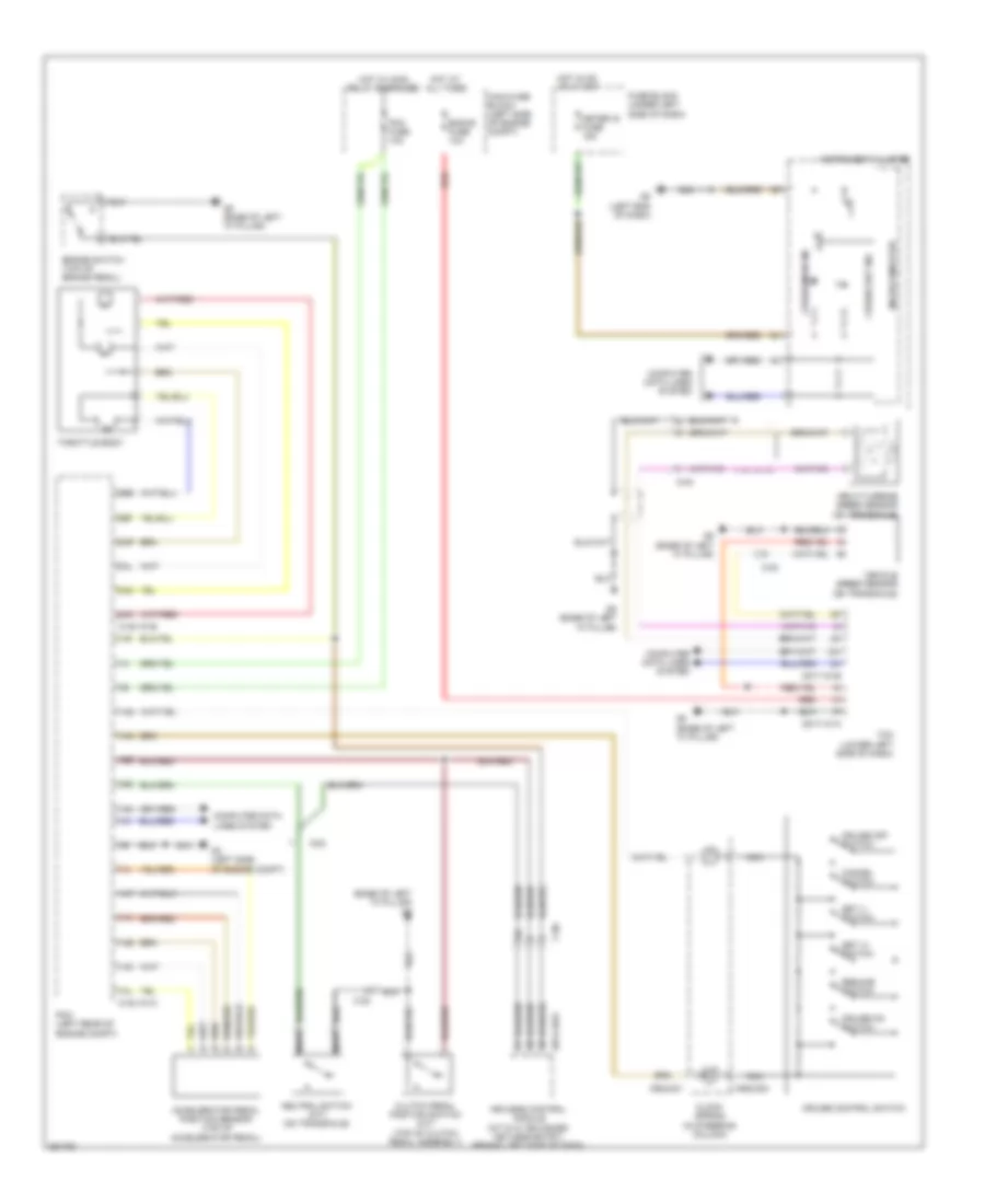
CRUISE CONTROL
2.5L
2.5L, Cruise Control Wiring Diagram for Mazda 6 i Grand Touring 2011
List of elements for 2.5L, Cruise Control Wiring Diagram for Mazda 6 i Grand Touring 2011:
- (base of left "a" pillar) g5
- 0140-101a
- 0140-101b
- 0517-101a
- 0517-101b
- 0914-401c
- 0922-201
- 0922-202
- 1af
- 1ai
- 1al
- 1am
- 1an
- 1ao
- 1ap
- 1aq
- 1as
- 1av
- 1bc
- 1bd
- 2ak
- 2al
- 2ao
- 2ap
- 2be
- 2bf
- Accelerator pedal position sensor (top of accelerator pedal)
- Brake switch (top of brake pedal)
- C-02
- C-06
- Cancel switch
- Clock spring (in steering column)
- Clutch pedal position switch (m/t) (top of clutch pedal assembly)
- Computer data lines system
- Cruise control switch
- Cruise main ind
- Cruise off switch
- Cruise on switch
- Cruise set ind
- Eng+b fuse 10a
- Fuse block (under left side of dash)
- G3 (left side of engine compt)
- G5 (base of left "a" pillar)
- G8 (left end of dash)
- Hot at all times
- Hot in on or start
- Hot w/ main relay energized
- Input/turbine speed sensor (on transaxle)
- Instrument cluster
- Keyless control module (m/t & w/ advanced keyless entry) (behind left side of dash)
- Main fuse block (left side of engine compt)
- Meter ig fuse 15a
- Microcomputer
- Nca
- Neutral switch (m/t) (on transaxle)
- Pcm (left rear of engine compt)
- Pcm fuse 10a
- Red
- Resume switch
- Set (+) switch
- Set (-) switch
- Tcm (lower left side of dash)
- Throttle body
- Vehicle speed sensor (on transaxle)
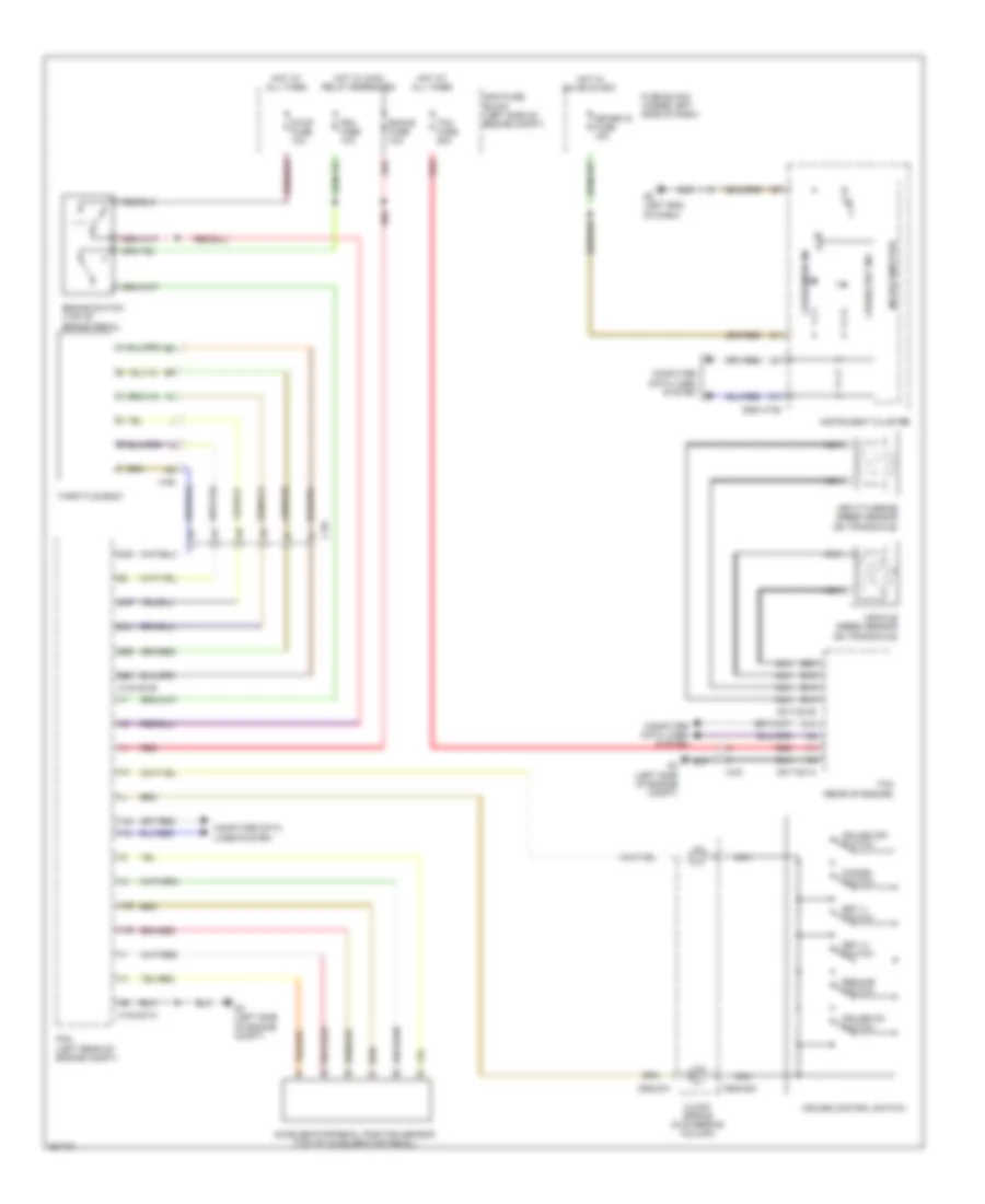
3.7L
3.7L, Cruise Control Wiring Diagram for Mazda 6 i Grand Touring 2011
List of elements for 3.7L, Cruise Control Wiring Diagram for Mazda 6 i Grand Touring 2011:
- 0140-201a
- 0140-201b
- 0517-201a
- 0517-201b
- 0922-101b
- 0922-201
- 0922-202
- 1ab
- 1ad
- 1ah
- 1al
- 2al
- 2an
- 2ap
- 2bo
- 2br
- A14
- Accelerator pedal position sensor (top of accelerator pedal)
- B12
- B13
- B19
- B20
- Brake switch (top of brake pedal)
- C-02
- C-56
- C-58
- Cancel switch
- Clock spring (in steering column)
- Computer data lines system
- Cruise control switch
- Cruise main ind
- Cruise off switch
- Cruise on switch
- Cruise set ind
- Eng+b fuse 10a
- Fuse block (under left side of dash)
- G3 (left side of engine compt)
- G8 (left end of dash)
- Hot at all times
- Hot in on or start
- Hot w/ main relay energized
- Input/turbine speed sensor (on transaxle)
- Instrument cluster
- Main fuse block (left side of engine compt)
- Meter ig fuse 15a
- Microcomputer
- Nca
- Pcm (left rear of engine compt)
- Pcm fuse 10a
- Red
- Resume switch
- Set (+) switch
- Set (-) switch
- Stop fuse 10a
- Tcm (rear of engine)
- Tcm fuse 20a
- Throttle body
- Vehicle speed sensor (on transaxle)
DEFOGGERS
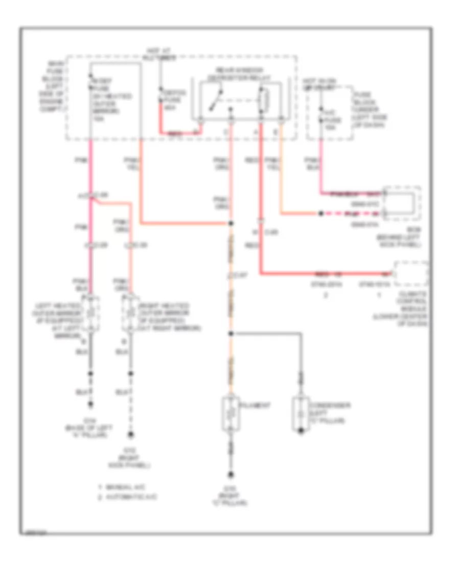
Defoggers Wiring Diagram for Mazda 6 i Grand Touring 2011
List of elements for Defoggers Wiring Diagram for Mazda 6 i Grand Touring 2011:
- 0740-101a
- 0740-201a
- 0940-01a
- 0940-01c
- 3ac
- A/c fuse 10a
- Automatic a/c
- Bcm (behind left kick panel)
- C-06 ac
- C-07
- C-29 i
- C-30 i
- Climate control module (lower center of dash)
- Condenser (left "c" pillar)
- Defog fuse 40a
- Filament
- Fuse block (under left side of dash)
- G10 (right "c" pillar)
- G12 (right kick panel)
- G14 (base of left "a" pillar)
- Hot at all times
- Hot in on or start
- Left heated outer mirror (if equipped) (at left mirror) b
- M def fuse (w/ heated outer mirror) 10a
- Main fuse block (left side of engine compt)
- Manual a/c
- Pnk
- Rear window defroster relay
- Red
- Right heated outer mirror (if equipped) (at right mirror)
- W c-05
ENGINE PERFORMANCE
2.5L
2.5L, Engine Performance Wiring Diagram (1 of 4) for Mazda 6 i Grand Touring 2011
List of elements for 2.5L, Engine Performance Wiring Diagram (1 of 4) for Mazda 6 i Grand Touring 2011:
- (top of brake pedal) brake switch
- 0140-101a
- 0914-401c
- 1aa
- 1ab
- 1ac
- 1ad
- 1ae
- 1af
- 1ag
- 1ah
- 1ai
- 1aj
- 1ak
- 1al
- 1am
- 1an
- 1ao
- 1ap
- 1aq
- 1ar
- 1as
- 1at
- 1au
- 1av
- 1aw
- 1ax
- 1ay
- 1az
- 1ba
- 1bb
- 1bc
- 1bd
- 1be
- 1bf
- 1bg
- 1bh
- Accelerator pedal position sensor (top of accelerator pedal)
- Air conditioning system
- C-02
- C-06
- Clutch pedal position switch (m/t) (top of clutch pedal assembly)
- Computer data lines system
- Cooling fans system
- Cruise control system
- Eng +b fuse 10a
- Engine fuse 10a
- G3 (left side of engine compt)
- G5 (base of left "a" pillar)
- Hot at all times
- Keyless control module (w/ advanced keyless entry & push button start system & m/t) (behind left side of dash)
- Main fuse block (left side of engine compt)
- Main relay
- Neutral switch (m/t) (on transaxle)
- Pcm (left rear of engine compt)
- Pcm fuse 10a
- Red
- Starting/charging system
- Stop fuse 10a
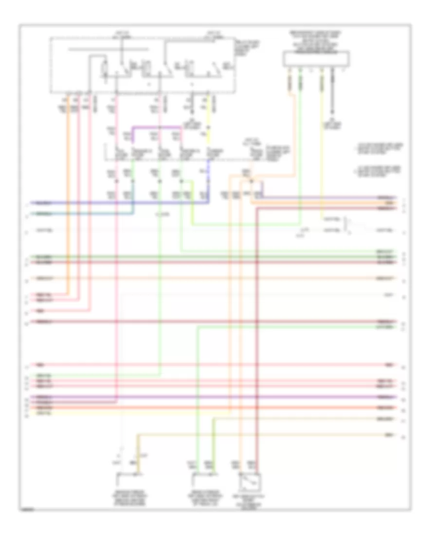
2.5L, Engine Performance Wiring Diagram (2 of 4) for Mazda 6 i Grand Touring 2011
List of elements for 2.5L, Engine Performance Wiring Diagram (2 of 4) for Mazda 6 i Grand Touring 2011:
- (in main fuse & relay box) check connector
- (under rear seat, on fuel tank) fuel pump unit/fuel gauge sender unit
- 0922-101b
- C-05
- C-06
- C-07
- C-11
- Canister vent solenoid valve (below right rear of luggage compt)
- Egi inj fuse 15a
- Eng ig fuse 15a
- Engine check ind
- Entry & push button start system
- Fuel gauge sender unit
- Fuel pump
- Fuel pump fuse 25a
- Fuel pump relay
- Fuel tank pressure sensor (on fuel tank)
- Fuse block (under left side of dash)
- G15 (under rear seat)
- G8 (left end of dash)
- Hego fuse 5a
- Hot at all times
- Hot in run or start
- Hot w/ ig1 relay energized
- Instrument cluster
- Main fuse block (left side of engine compt)
- Mass air flow/intake air temperature sensor (rear of engine)
- Meter ig fuse 15a
- Micro computer
- Red
- Refrigerant pressure sensor (right front of engine compt)
- W/ advanced keyless
- W/o advanced keyless entry & push button start system
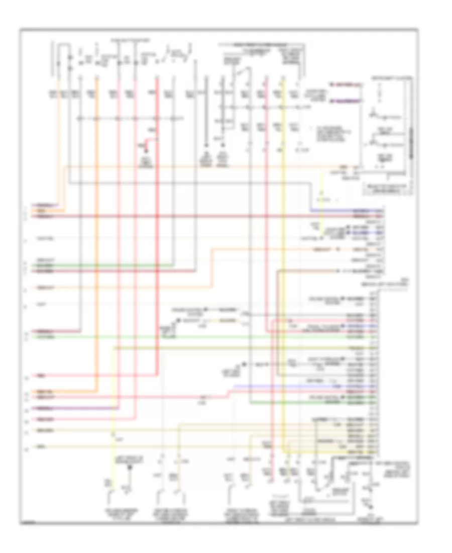
2.5L, Engine Performance Wiring Diagram (3 of 4) for Mazda 6 i Grand Touring 2011
List of elements for 2.5L, Engine Performance Wiring Diagram (3 of 4) for Mazda 6 i Grand Touring 2011:
- (left rear of engine compt) a/f sensor
- (right rear engine) variable tumble shutter valve switch
- (top right side of engine)
- C-02
- C-04
- C-05
- Camshaft position sensor (right rear of engine)
- Crankshaft position sensor (right front of engine)
- G4 (right rear of engine)
- G5 (base of left "a" pillar)
- Hall ic
- Igniter
- Ignition coil 1
- Ignition coil 2
- Ignition coil 3
- Ignition coil 4
- Manifold absolute pressure sensor (left rear of engine)
- Nca
- Red
- Throttle body (top rear of engine)
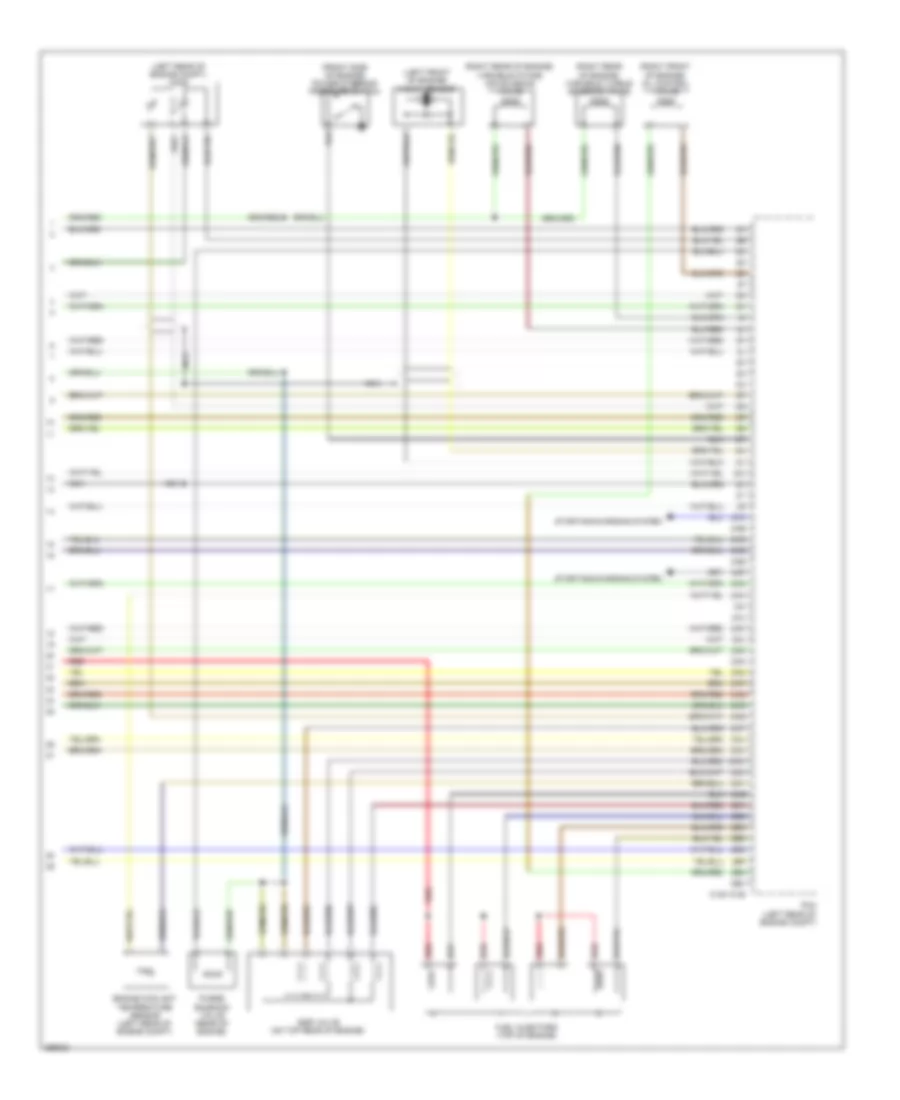
2.5L, Engine Performance Wiring Diagram (4 of 4) for Mazda 6 i Grand Touring 2011
List of elements for 2.5L, Engine Performance Wiring Diagram (4 of 4) for Mazda 6 i Grand Touring 2011:
- (front side of engine) power steering pressure switch
- (left front of engine) knock sensor
- (left rear of engine compt) ho2s
- (right front of engine) oil control valve
- (right rear of engine) variable intake air solenoid valve
- (right rear of engine) variable tumble solenoid valve
- 0140-101b
- 2aa
- 2ab
- 2ac
- 2ad
- 2ae
- 2af
- 2ag
- 2ah
- 2ai
- 2aj
- 2ak
- 2al
- 2am
- 2an
- 2ao
- 2ap
- 2aq
- 2ar
- 2as
- 2at
- 2au
- 2av
- 2aw
- 2ax
- 2ay
- 2az
- 2ba
- 2bb
- 2bc
- 2bd
- 2be
- 2bf
- 2bg
- 2bh
- Egr valve (on top rear of engine)
- Engine coolant temperature sensor (left rear of engine compt)
- Fuel injectors (top of engine)
- Nca
- Pcm (left rear of engine compt)
- Purge solenoid valve (rear of engine)
- Red
- Starting/charging system
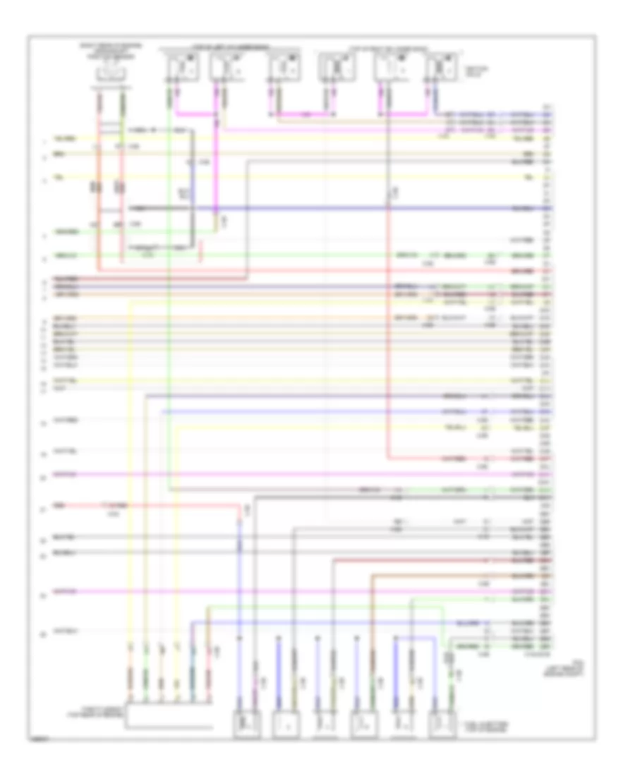
3.7L
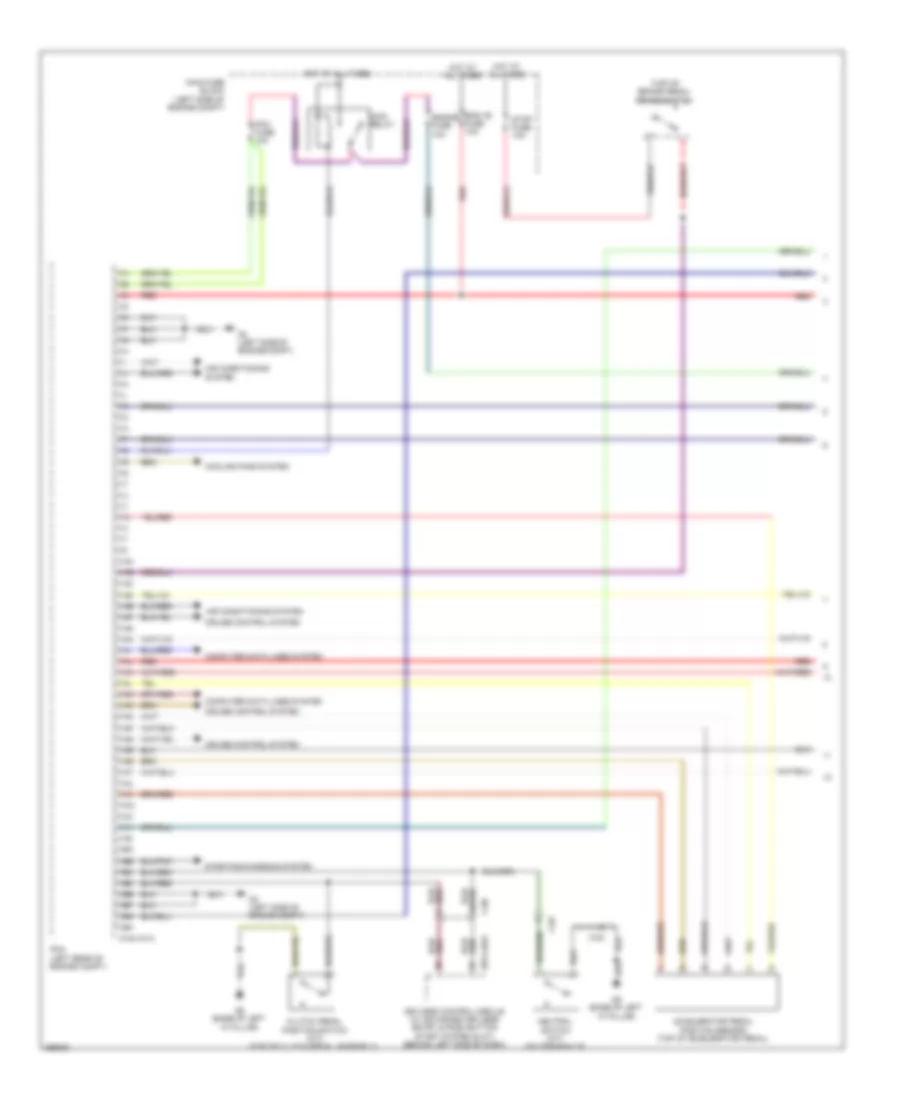
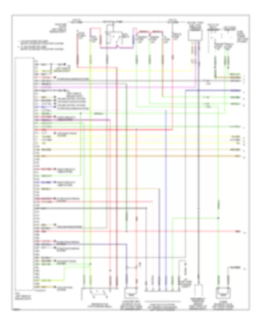
3.7L, Engine Performance Wiring Diagram (1 of 4) for Mazda 6 i Grand Touring 2011
List of elements for 3.7L, Engine Performance Wiring Diagram (1 of 4) for Mazda 6 i Grand Touring 2011:
- (left rear of engine compt)
- (on fuel tank) fuel tank pressure sensor
- 0140-201a
- 1aa
- 1ab
- 1ac
- 1ad
- 1ae
- 1af
- 1ag
- 1ah
- 1ai
- 1aj
- 1ak
- 1al
- 1am
- 1an
- 1ao
- 1ap
- 1aq
- 1ar
- 1as
- 1at
- 1au
- 1av
- 1aw
- 1ax
- 1ay
- 1az
- 1ba
- 1bb
- 1bc
- 1bd
- 1be
- 1bf
- 1bg
- 1bh
- 1bi
- 1bj
- 1bk
- 1bl
- 1bm
- 1bn
- 1bo
- 1bp
- 1bq
- 1br
- Air conditioning system
- Brake switch (top of brake pedal)
- C-02
- C-06
- Canister vent solenoid valve (below right rear of luggage compt)
- Computer data lines system
- Cooling fans system
- Cruise control system
- Eng +b fuse 10a
- Eng ig fuse 15a
- Engine 2 fuse 15a
- Engine fuse 20a
- Fuse block (under left side of dash)
- G3 (left side of engine compt)
- Hot at all times
- Hot in run or start
- Hot w/ ig1 relay energized
- Ig fuse 20a
- Main fuse block (left side of engine compt)
- Main relay
- Mass air flow/intake air temperature sensor (left rear of engine)
- Meter fuse 15a
- Pcm
- Pcm fuse 10a
- Purge solenoid valve (left rear corner of engine compt)
- Red
- Refrigerant pressure sensor (right front of engine compt)
- Starting/charging system
- Stop fuse 4 10a
- W/ advanced keyless entry & push button start system
- W/o advanced keyless entry & push button start system
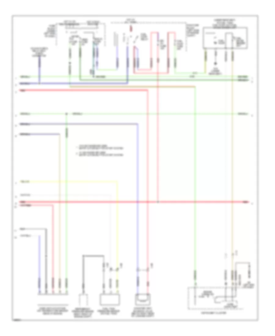
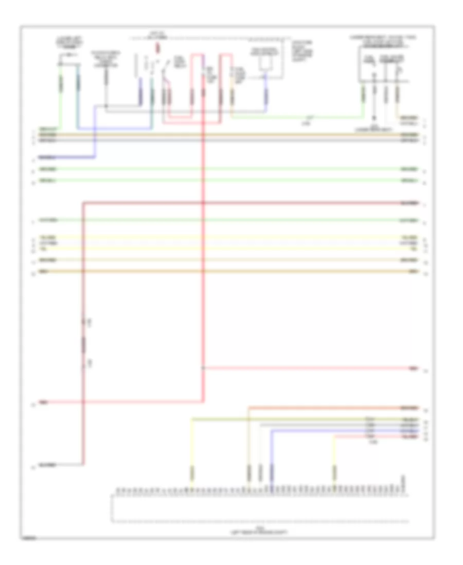
3.7L, Engine Performance Wiring Diagram (2 of 4) for Mazda 6 i Grand Touring 2011
List of elements for 3.7L, Engine Performance Wiring Diagram (2 of 4) for Mazda 6 i Grand Touring 2011:
- (in main fuse & relay box) check connector
- (lower left side of dash) diode
- (under rear seat, on fuel tank) fuel pump unit/fuel gauge sender unit
- 0140-201c
- 3aa
- 3ab
- 3ac
- 3ad
- 3ae
- 3af
- 3ag
- 3ah
- 3ai
- 3aj
- 3ak
- 3al
- 3am
- 3an
- 3ao
- 3ap
- 3aq
- 3ar
- 3as
- 3at
- 3au
- 3av
- 3aw
- 3ax
- C-02
- C-06
- C-56
- Egi inj fuse 15a
- Fan control module relay
- Fuel gauge sender unit
- Fuel pump
- Fuel pump fuse 25a
- Fuel pump relay
- G15 (under rear seat)
- Hot at all times
- Main fuse block (left side of engine compt)
- Pcm (left rear of engine compt)
- Red
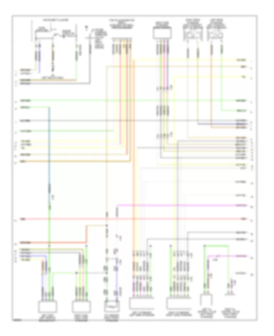
3.7L, Engine Performance Wiring Diagram (3 of 4) for Mazda 6 i Grand Touring 2011
List of elements for 3.7L, Engine Performance Wiring Diagram (3 of 4) for Mazda 6 i Grand Touring 2011:
- (left rear of engine) left camshaft position sensor
- (right rear of engine) right camshaft position sensor
- (right side of engine) knock sensor
- (top of accelerator pedal) accelerator pedal position sensor
- 0140-237
- 0922-101b
- C-56
- C-58
- C-59
- Cht sensor (right front of engine)
- Engine check ind
- G8 (left end of dash)
- Instrument cluster
- Left a/f sensor (left rear of engine)
- Left ho2s (left rear of engine compt)
- Left oil control valve (left front of engine)
- Micro computer
- Power steering pressure switch (left front side of engine)
- Red
- Right a/f sensor (right side of engine)
- Right ho2s (right side of engine)
- Right oil control valve (right front of engine)
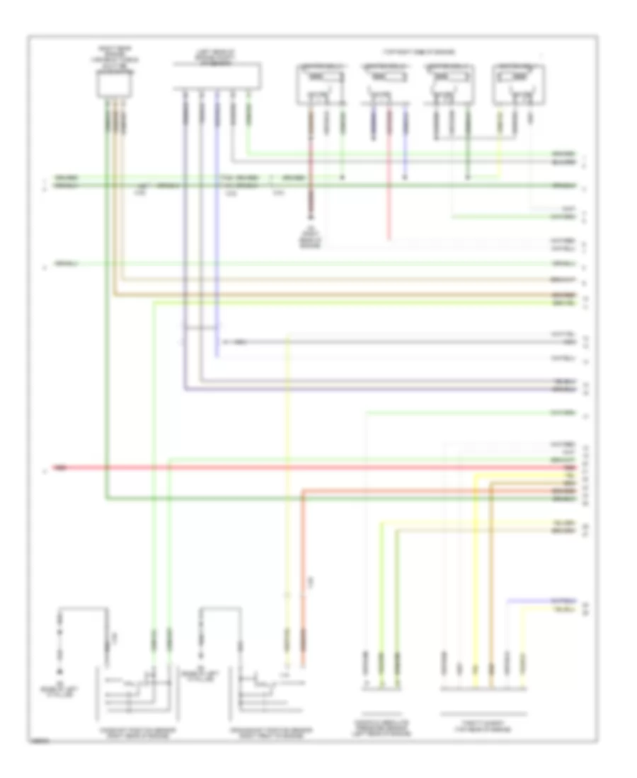
3.7L, Engine Performance Wiring Diagram (4 of 4) for Mazda 6 i Grand Touring 2011
List of elements for 3.7L, Engine Performance Wiring Diagram (4 of 4) for Mazda 6 i Grand Touring 2011:
- (right rear of engine) crankshaft position sensor
- (top of left cylinder bank)
- (top of right cylinder bank)
- 0140-201b
- 2aa
- 2ab
- 2ac
- 2ad
- 2ae
- 2af
- 2ag
- 2ah
- 2ai
- 2aj
- 2ak
- 2al
- 2am
- 2an
- 2ao
- 2ap
- 2aq
- 2ar
- 2as
- 2at
- 2au
- 2av
- 2aw
- 2ax
- 2ay
- 2az
- 2ba
- 2bb
- 2bc
- 2bd
- 2be
- 2bf
- 2bg
- 2bh
- 2bi
- 2bj
- 2bk
- 2bl
- 2bm
- 2bn
- 2bo
- 2bp
- 2bq
- 2br
- C-02
- C-56
- C-58
- C-59
- Fuel injectors (top of engine)
- Ignition coils
- Nca
- Pcm (left rear of engine compt)
- Red
- Throttle body (top rear of engine)
EXTERIOR LIGHTS
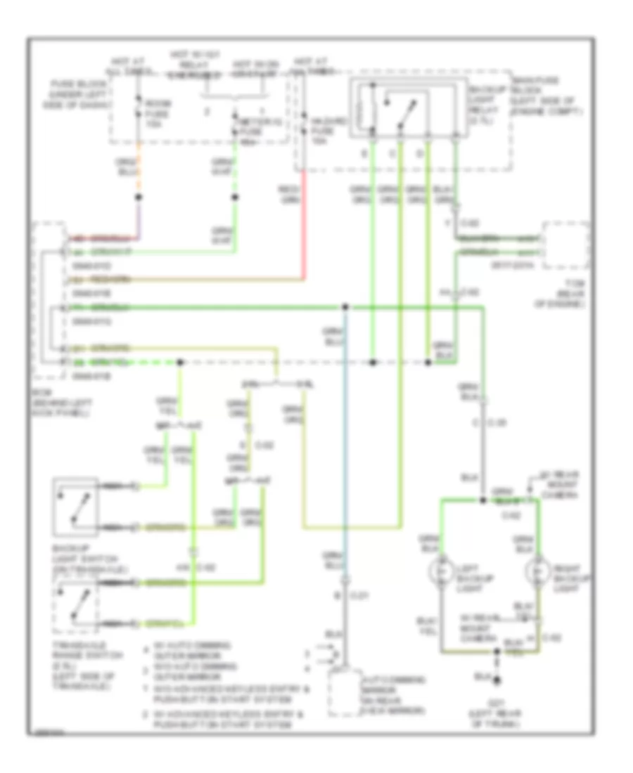
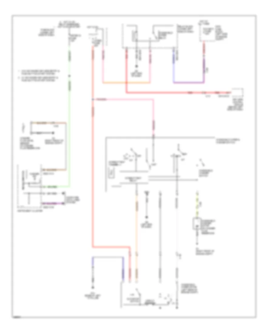
Backup Lamps Wiring Diagram for Mazda 6 i Grand Touring 2011
List of elements for Backup Lamps Wiring Diagram for Mazda 6 i Grand Touring 2011:
- 0517-201a
- 0940-01b
- 0940-01d
- 0940-01g
- 2.5l
- 3.7l
- A/t
- A11
- A13
- Aa c-02
- An c-02
- Auto dimming mirror (in rear view mirror)
- B c-21
- Backup light relay (3.7l)
- Backup light switch (on transaxle)
- Bcm (behind left kick panel)
- C c-35
- C-62
- Fuse block (under left side of dash)
- G21 (left rear of trunk)
- Hazard fuse 10a
- Hot at all times
- Hot in on or start
- Hot w/ ig1 relay energized
- Left backup light
- M/t
- Main fuse block (left side of engine compt)
- Meter ig fuse 15a
- Nca
- Right backup light
- Room fuse 15a
- S c-02
- Tcm (rear of engine)
- Transaxle range switch (2.5l) (left side of transaxle)
- W/ advanced keyless entry & push button start system
- W/ auto dimming outer mirror w/o auto dimming outer mirror
- W/ rear mount camera
- W/o advanced keyless entry & push button start system
- Y c-02
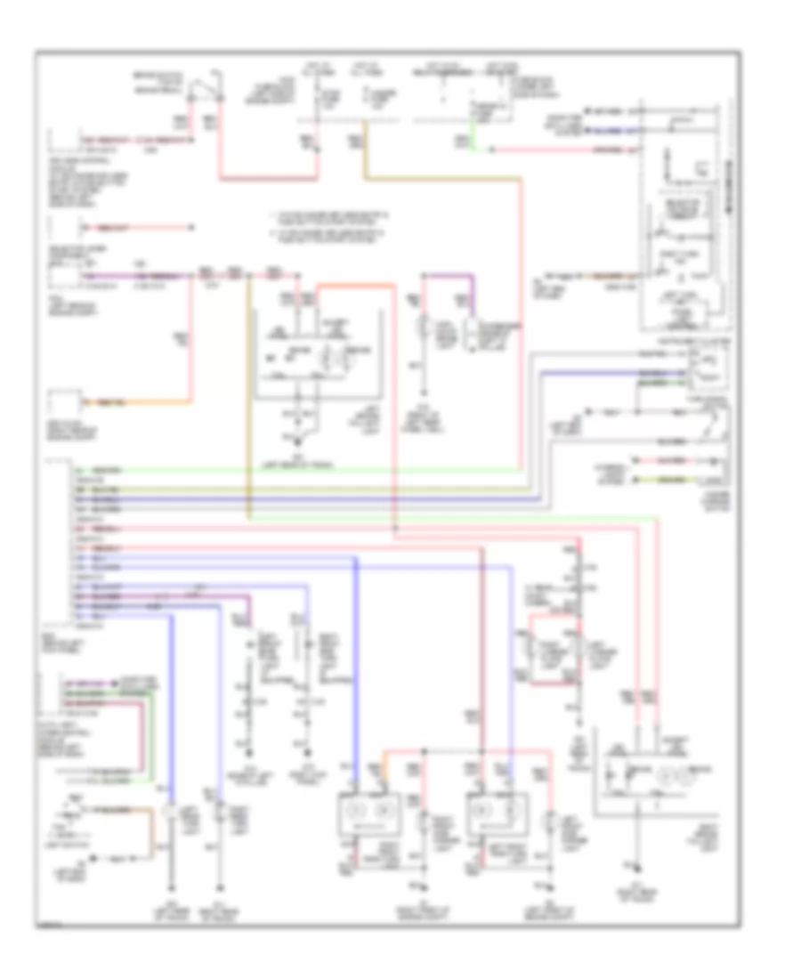
Exterior Lamps Wiring Diagram for Mazda 6 i Grand Touring 2011
List of elements for Exterior Lamps Wiring Diagram for Mazda 6 i Grand Touring 2011:
- (left front of engine compt)
- (right front of engine compt)
- 0140-101a
- 0140-201a
- 0914-401c
- 0918-101b
- 0922-101b
- 0940-01a
- 0940-01b
- 0940-01c
- 0940-01h
- 1ab
- 2.5l
- 3.7l
- Ao c-30
- Auto
- Auto light/ wiper control module (behind left side of dash)
- B c-29
- Bcm (behind left kick panel)
- Brake
- Brake switch (top of brake pedal)
- C-06
- C-07
- C-29
- C-30
- C-35 e
- Computer
- Computer data lines system
- Condenser (base of left "c" pillar)
- Data lines system
- Dsc hu/cm (right rear of engine compt)
- E c-62
- Except led type
- Fuse block (under left side of dash)
- G11 (right rear of trunk)
- G12 (right kick panel)
- G14 (base of left "a" pillar)
- G18 (front of left rear wheel well)
- G21 (left rear of trunk)
- G8 (left end of dash)
- Hazard fuse 10a
- Hazard warning switch
- Head
- High- mount brake light
- Hot at all times
- Hot in on or start
- Hot w/ ig1 relay energized
- Instrument cluster
- Interior lights system
- Keyless control module (w/ advanced keyless entry & push button start system) (behind left side of dash)
- Led type
- Left
- Left brake/ taillight light
- Left front park/turn light
- Left front side marker light
- Left front side turn light (if equipped)
- Left license plate light
- Left rear turn light
- Left turn ind
- Light switch
- Main fuse block (left side of engine compt)
- Meter ig fuse 15a
- Microcomputer
- Nca
- Off
- Panel light control
- Pcm (left rear of engine compt)
- Red
- Right
- Right brake/ taillight light
- Right front park/turn light
- Right front side marker light
- Right front side turn light (if equipped)
- Right license plate light
- Right rear turn light
- Right turn ind
- Selector ind drive circuit
- Selector lever component (a/t)
- Stop fuse 10a
- Tail
- Tns
- Turn signal switch
- W/ advanced keyless entry & push button start system
- W/ rear mount camera
- W/o advanced keyless entry & push button start system
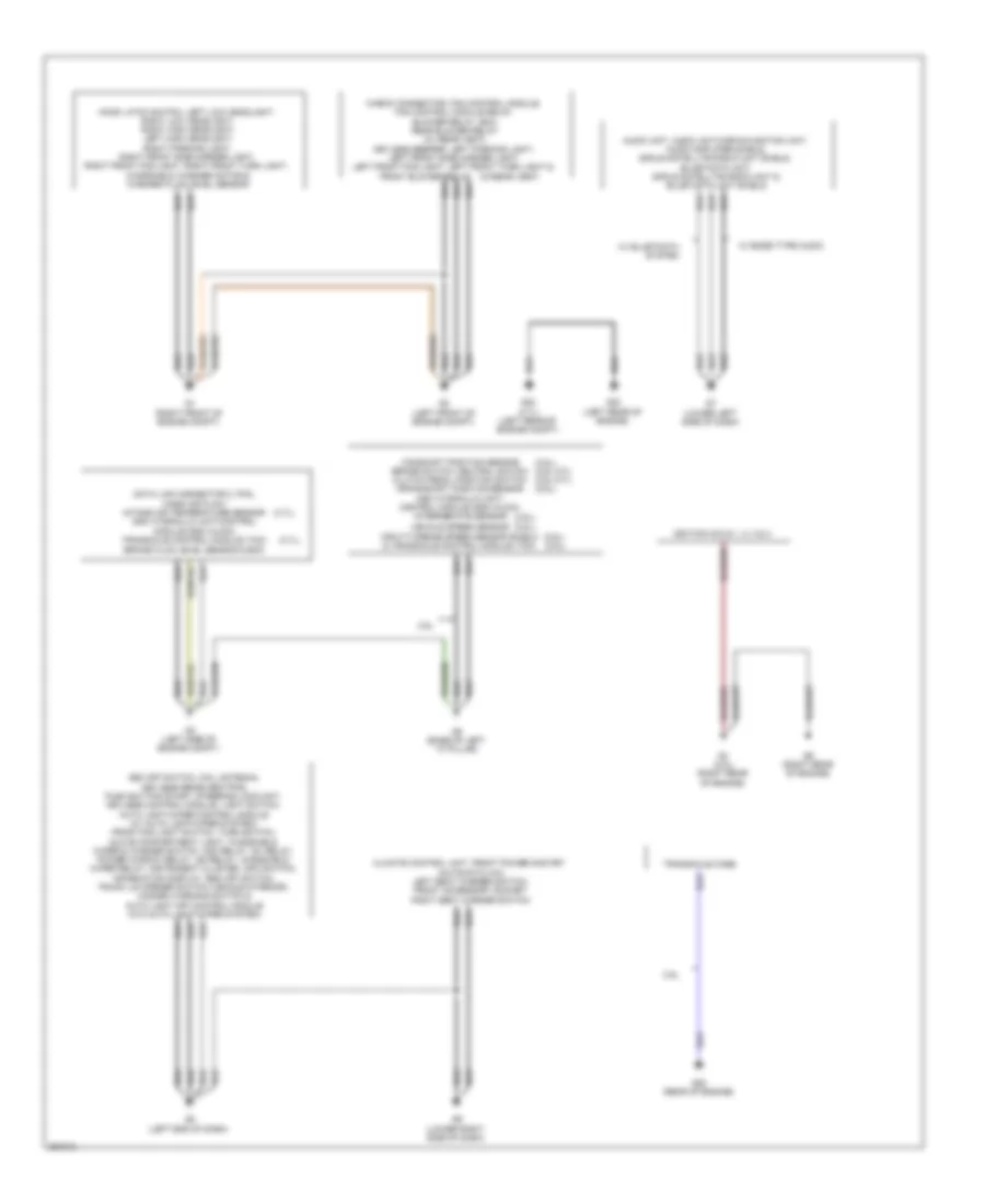
GROUND DISTRIBUTION
Ground Distribution Wiring Diagram (1 of 2) for Mazda 6 i Grand Touring 2011
List of elements for Ground Distribution Wiring Diagram (1 of 2) for Mazda 6 i Grand Touring 2011:
- (2.5l) (2.5l)
- (2.5l),
- (2.5l), (2.5l m/t), (2.5l m/t), (2.5l),
- (3.7l),
- (w/rear vent)
- 2.5l
- Camshaft position sensor brake switch, neutral switch clutch pedal position switch crankshaft position sensor dsc hydraulic unit/ control module (dsc hu/cm), intermediate sensor
- Check connector, fan control module, fan control module relay, blower relay, bcm, rear blower relay (w/ rear vent), keyless beeper, left parking light, left front side marker light, left front fog light, left front turn light &
- Climate control unit, front power mos fet (automatic a/c), left seat warmer switch, front accessory socket right seat warmer switch
- Data link connector 2, pcm, mass air flow/ intake air temperature sensor dsc hydraulic unit/control module (dsc hu/cm), transaxle control module (tcm) brake fluid level sensor & bcm
- Dsc off switch, coil antenna, keyless receiver/tpms, push button start, steering lock unit, keyless control module, light switch, auto light/wiper control module (w/ auto light/wiper system), front fog light switch, turn switch, glove compartment light, windshield wiper & washer switch, acc relay, ig1 relay, power window relay, ig2 relay, windshield wiper relay, instrument cluster, info switch, information display, bsm off switch, trunk lid opener switch (vehicle interior), hazard warning switch & auto light off control module (w/o auto light/wiper system)
- Front blower relay
- G1 (right front of engine compt)
- G2 (left front of engine compt)
- G20 (rear of engine)
- G22 (3.7l) (left rear of engine compt)
- G23 (left rear of engine)
- G3 (left side of engine compt)
- G4 (2.5l) (right rear of engine)
- G5 (base of left "a" pillar)
- G6 (right rear of engine)
- G7 (lower left side of dash)
- G8 (left end of dash)
- G9 (lower right side of dash)
- Hood latch switch, left low headlight, right low headlight, right high headlight, left high headlight, right parking light, right front side marker light, right front fog light, right front turn light, windshield washer motor & washer fluid-level sensor
- Ignition coils 1, 2, 3 & 4
- Input/turbine speed sensor shield & transaxle control module (tcm)
- Transaxle case
- Vehicle speed sensor
- W/ bose type audio
Ground Distribution Wiring Diagram (2 of 2) for Mazda 6 i Grand Touring 2011
List of elements for Ground Distribution Wiring Diagram (2 of 2) for Mazda 6 i Grand Touring 2011:
- (if equipped),
- (if equipped), power outer mirror switch/ retractable outer mirror switch, auto dimming mirror, left front door latch & lock actuator, left rear door latch & lock actuator, left door lock switch, left front outer handle, sunroof motor, keyless control module, left side turn
- (w/ rear vent),
- 2.5l
- Audio amplifier & microphone shield
- Combined sensor & rear power mos fet (w/ rear vent)
- Driver side buckle switch, left seat warmer module, position memory control module, sas control module, passenger side buckle switch, sas control module shield, seat weight sensor control module, power seat switch & right seat warmer module
- Filament
- Fuel pump unit
- G10 (right "c" pillar)
- G11 (right rear of trunk)
- G12 (right kick panel)
- G13 (front of right
- G14 (base of left "a" pillar)
- G15 (under rear seat)
- G16 (under right front passenger's seat)
- G17 (under driver's seat)
- G18 (front of left rear wheel well)
- G19 (2.5l) (on transaxle)
- G21 (left rear of trunk)
- G24 (2.5l) (left rear of engine compt)
- G25 (rear of engine)
- G26 (right side of engine compt)
- G27 (right side of engine compt)
- High mount brake light, trunk lid
- Illumination, right vanity mirror illumination, windshield wiper motor, auto light sensor/ rain sensor & left bsm indicator light
- Left license plate light, right license plate light, left taillight, left rear turn light, left backup light, right backup light, left brake light, left bsm control module & right bsm control module
- Left vanity mirror
- Light
- Opener, interior light, trunk compartment light switch & map light
- Outer mirror
- Power window main switch, left heated
- Rear accessory socket
- Rear fan switch
- Rear wheel well)
- Right front outer handle & right bsm indicator light
- Right taillight, right rear turn light & right brake light
- Selector lever component, right heated outer mirror (if equipped), right door lock switch, right front power window sub switch, right front door latch & lock actuator, right rear door latch & lock actuator, right side
- Transaxle case
- Turn light
- W/ bose type audio
- W/ rear vent
- W/ seat weight sensor
HEADLIGHTS
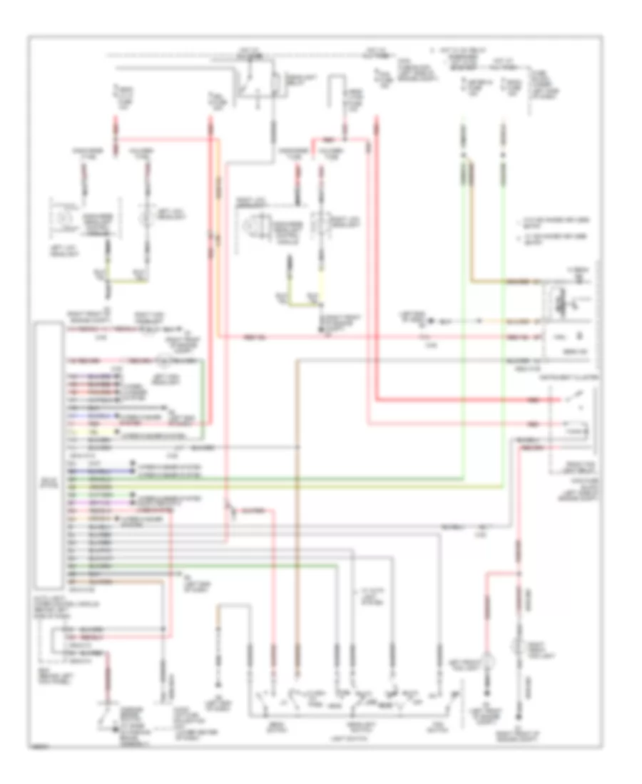
Headlights Wiring Diagram, with DRL for Mazda 6 i Grand Touring 2011
List of elements for Headlights Wiring Diagram, with DRL for Mazda 6 i Grand Touring 2011:
- (at base of parking brake assembly)
- (left end of dash) g8
- (right front of engine compt)
- 0918-101a
- 0918-101b
- 0918-303
- 0920-301a
- 0922-101b
- 0940-01c
- 0940-01h
- Audio unit/car- navigation unit (lower center of dash)
- Auto
- Auto light/ wiper control module (behind left side of dash)
- Bcm (behind left kick panel)
- Beam ind
- Beam switch
- C-05
- Discharge headlight control module
- Discharge type
- Drl fuse 20a
- Entry
- Flash- to- pass
- Fog fuse 15a
- Fog switch
- Front fog light relay
- Fuse block (under left side of dash)
- G1 (right front of engine compt)
- G2 (left front of engine compt)
- G8 (left end of dash)
- Halogen type
- Head
- Head lo lh fuse 10a
- Head lo rh fuse 10a
- Headlight relay
- Headlight switch
- Hi beam ind
- Hot at all times
- Hot w/ ig1 relay energized hot in on or start
- Instrument cluster
- Left front fog light
- Left high headlight
- Left low headlight
- Light switch
- Main fuse block (left side of engine compt)
- Meter ig fuse 15a
- Micro computer
- Nca
- Of engine compt) g1
- Off
- Parking brake switch
- Red
- Right front fog light
- Right high headlight
- Right low headlight
- Room fuse 15a
- Solid
- State
- Tns
- W/ advanced keyless
- W/ auto light system
- W/o advanced keyless
- Wiper/ washer system
- Wiper/washer system
- Wiper/washer system computer data lines system
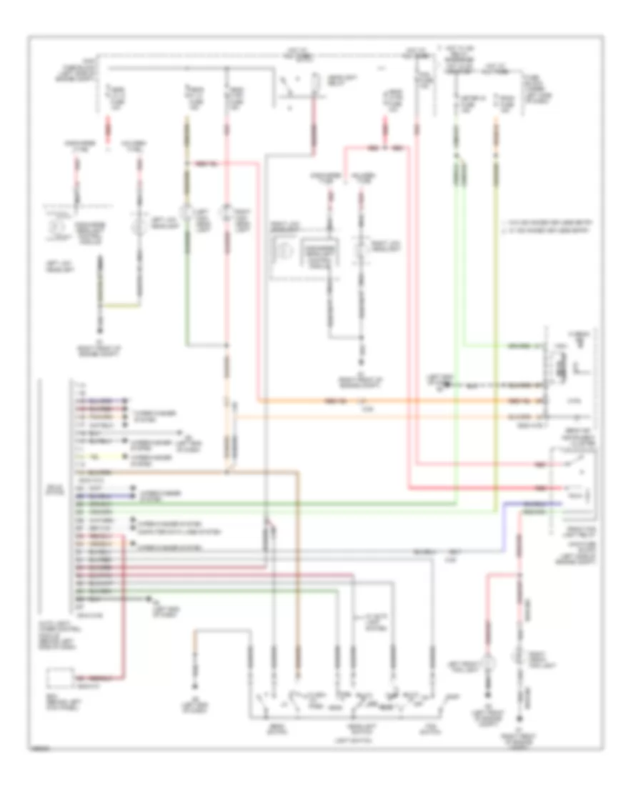
Headlights Wiring Diagram, without DRL for Mazda 6 i Grand Touring 2011
List of elements for Headlights Wiring Diagram, without DRL for Mazda 6 i Grand Touring 2011:
- (left end of dash)
- 0918-101a
- 0918-101b
- 0918-303
- 0922-101b
- 0940-01c
- Auto
- Auto light/ wiper control module (behind left side of dash)
- Bcm (behind left kick panel)
- Beam ind
- Beam switch
- C-05
- Computer data lines system
- Computer micro
- Discharge headlight control module
- Discharge type
- Flash- to- pass
- Fog fuse 15a
- Fog switch
- Front fog light relay
- Fuse block (under left side of dash)
- G1 (right front of engine compt)
- G2 (left front of engine compt)
- G8 (left end of dash)
- Halogen type
- Head
- Head hi lh fuse 15a
- Head hi rh fuse 15a
- Head lo lh fuse 10a
- Head lo rh fuse 10a
- Headlight relay
- Headlight switch
- Hi beam ind
- Hot at all times
- Hot w/ ig2 relay energized hot in on or start
- Instrument cluster
- Left front fog light
- Left high head- light
- Left low headlight
- Light switch
- Main fuse block (left side of engine compt)
- Meter ig fuse 15a
- Nca
- Off
- Red
- Right front fog light
- Right high head- light
- Right low headlight
- Room fuse 15a
- Solid state
- Tns
- W/ advanced keyless entry
- W/ auto light system
- W/o advanced keyless entry
- Wiper/washer system
HORN
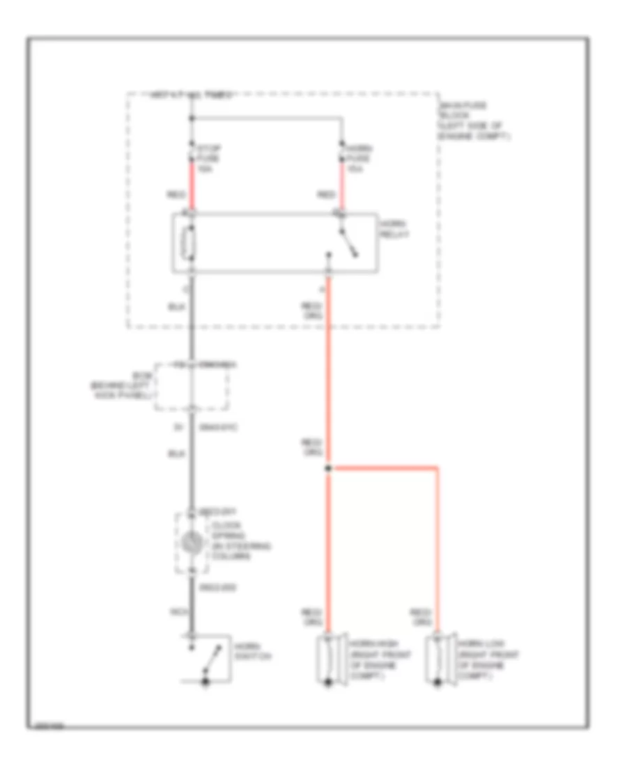
Horn Wiring Diagram for Mazda 6 i Grand Touring 2011
List of elements for Horn Wiring Diagram for Mazda 6 i Grand Touring 2011:
- (right front of engine compt)
- 0922-201
- 0922-202
- 0940-01a
- 0940-01c
- Bcm (behind left kick panel)
- Clock spring (in steering column)
- Horn fuse 15a
- Horn high
- Horn low
- Horn relay
- Horn switch
- Hot at all times
- Main fuse block (left side of engine compt)
- Nca
- Red
- Stop fuse 10a
INSTRUMENT CLUSTER
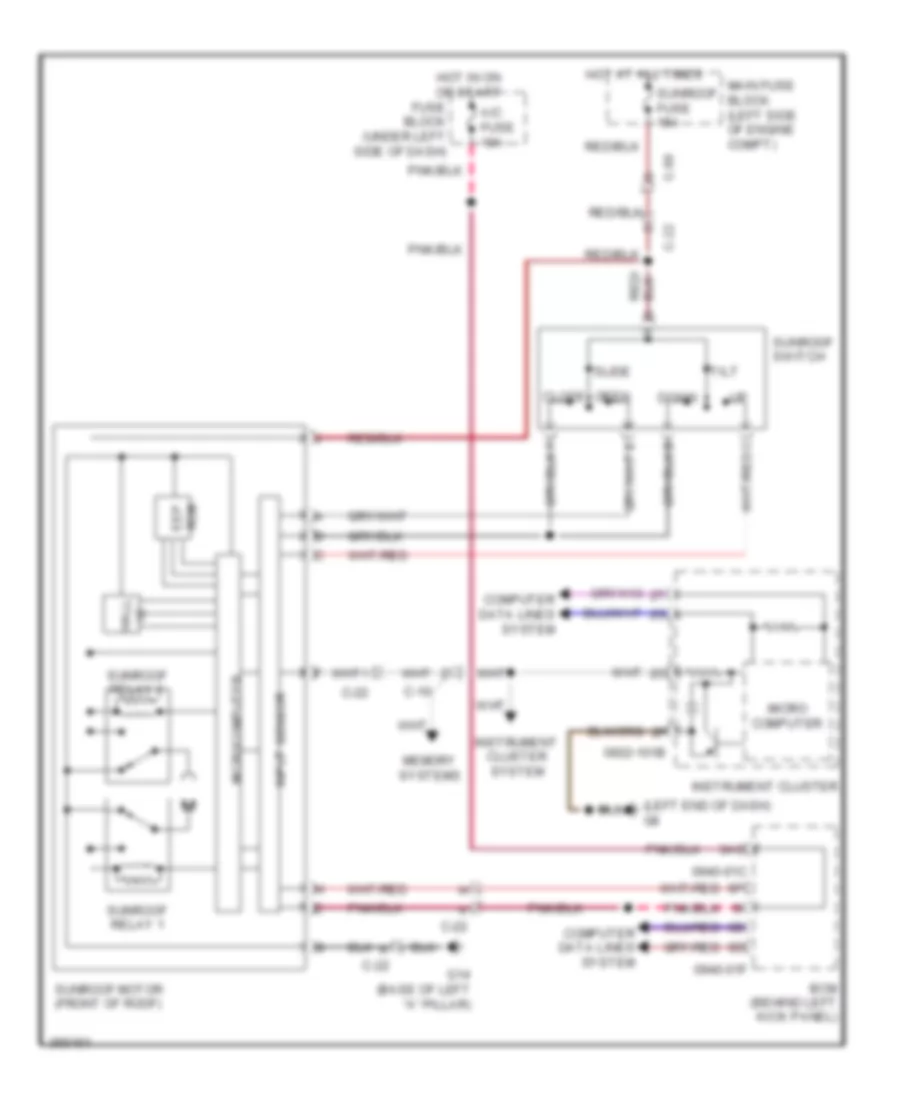
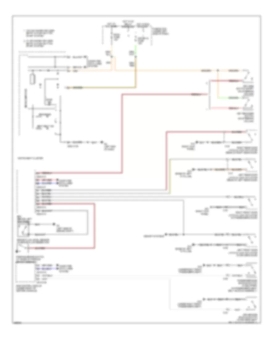
Instrument Cluster Wiring Diagram (1 of 2) for Mazda 6 i Grand Touring 2011
List of elements for Instrument Cluster Wiring Diagram (1 of 2) for Mazda 6 i Grand Touring 2011:
- (left end of dash) g8
- (right front of engine compt) ambient temperature sensor
- 0918-101b
- 0920-301a
- 0920-302a
- 0922-101a
- 0922-101b
- 0922-105
- 120 km/h ind
- 2.5l m/t
- 3.7l
- 4w abs ind
- A/t ind
- Air bag ind
- Air conditioning system
- Anti-theft system
- Audio amplifier (w/ bose) (above right kick panel)
- Audio unit/ car navigation unit (w/ bose) (if equipped) (lower center of dash)
- Auto light/ wiper control module (w/ auto wiper system) (behind left side of dash)
- Beam ind
- Brake ind
- Bsm off ind
- Buzzer
- C-02
- C-05
- C-10
- C-13
- C-22
- C-59
- Charge ind
- Check engine ind
- Circuit failure detec- tion
- Computer data lines system
- Cruise main ind
- Cruise set ind
- Dimmer cancel switch
- Door ind
- Dsc ind
- Dsc off ind
- Etc ind
- Fuel cap ind
- Fuel gauge
- Fuel low ind
- Fuse block (under left side of dash)
- G8 (left end of dash)
- Headlights system
- Hot at all times
- Hot w/ ig1 relay energized
- Illum ind
- Ind
- Instrument cluster
- Interior lights system
- Interior lights, air conditioning, sound & navigation systems
- Key (green)
- Key (red)
- Left turn ind
- Meter ig fuse 15a
- Microcomputer
- Odometer/trip meter, ambient temperature
- Oil ind
- Oil pressure switch (left side of engine)
- Panel light control
- Red
- Right turn ind
- Room fuse 15a
- Seat belt ind
- Secu- rity ind
- Selector ind
- Selector indicator drive circuit
- Speedometer
- St lock fail ind
- Sunroof motor (front of roof)
- Tacho meter
- Tns ind
- Tpms ind
- Tripmeter switch
- W/ advanced keyless entry & push button start system
- W/o advanced keyless entry & push button start system
- Washer ind
- Water temp gauge
- Wiper/washer system
Instrument Cluster Wiring Diagram (2 of 2) for Mazda 6 i Grand Touring 2011
List of elements for Instrument Cluster Wiring Diagram (2 of 2) for Mazda 6 i Grand Touring 2011:
- & push button start system
- (base of left "a" pillar)
- (base of left "a" pillar) g14
- (left side of engine compt) g3
- (right kick panel) g12
- 0913-201a
- 0914-401b
- 0940-01a
- 0940-01c
- 0940-01h
- 0940-1f
- Bcm (behind left kick panel)
- Brake fluid level sensor (in brake fluid reservoir)
- C-10
- C-13
- C-29
- C-30
- C-31
- C-32
- Computer data lines system
- F c-11
- Fuel pump unit/fuel gauge sender unit (under rear seat, on fuel tank)
- G c-24
- G14
- J c-24
- Keyless control module (behind left side of dash)
- Keyless receiver/tpms control module (behind right side of dash)
- Left front door latch & lock actuator (in driver's door)
- Left rear door latch & lock actuator (rear of left rear door)
- Parking brake switch (at base of parking brake assembly)
- Position memory control module (w/ memory) (under driver's seat)
- Right front door latch & lock actuator (in passenger's door)
- Right rear door latch & lock actuator (rear of right rear door)
- W/ advanced keyless entry
- W/o advanced keyless entry
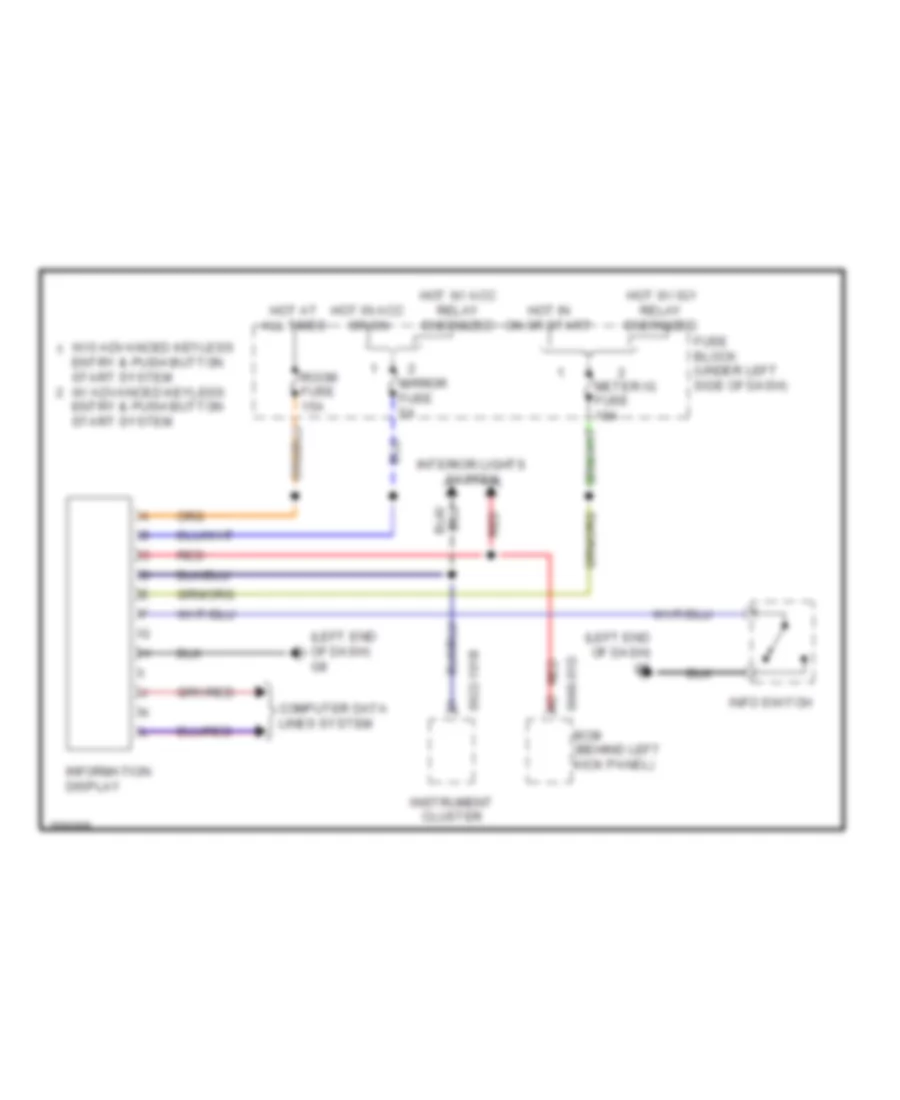
Multi-Information System Wiring Diagram for Mazda 6 i Grand Touring 2011
List of elements for Multi-Information System Wiring Diagram for Mazda 6 i Grand Touring 2011:
- (left end of dash) g8
- 0922-101b
- 0940-01d
- Bcm (behind left kick panel)
- Computer data lines system
- Entry & push button start system
- Entry & push button start system w/ advanced keyless
- Fuse block (under left side of dash)
- Hot at all times
- Hot in acc or on
- Hot in on or start
- Hot w/ acc relay energized
- Hot w/ ig1 relay energized
- Info switch
- Information display
- Instrument cluster
- Interior lights system
- Meter ig fuse 15a
- Mirror fuse 5a
- Red
- Room fuse 15a
- W/o advanced keyless
INTERIOR LIGHTS
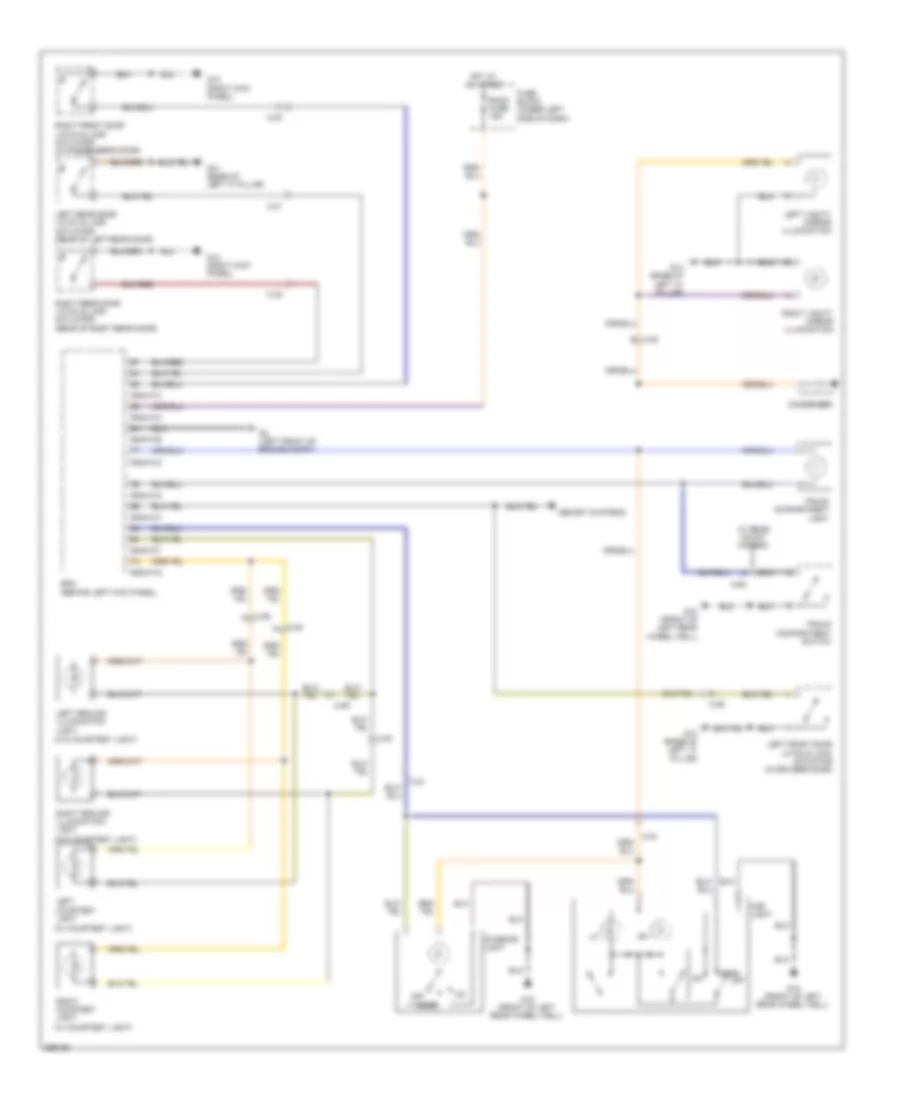
Courtesy Lamps Wiring Diagram for Mazda 6 i Grand Touring 2011
List of elements for Courtesy Lamps Wiring Diagram for Mazda 6 i Grand Touring 2011:
- (w/ courtesy light)
- (w/o courtesy light)
- 0940-01b
- 0940-01d
- 0940-01f
- 0940-01g
- 0940-01h
- Bcm (behind left kick panel)
- C-22 b
- C-29
- C-29 ai
- C-30
- C-30 al
- C-30 i
- C-31
- C-32
- C-34
- C-62
- Condenser
- Door
- Fuse block (under left side of dash)
- G12 (right kick panel)
- G14 (base of left "a" pillar)
- G18 (front of left rear wheel well)
- G2 (left front of engine compt)
- Hot at all times
- Interior light
- Left courtesy light
- Left front door latch & lock actuator (in driver's door)
- Left ground illumination light
- Left rear door latch & lock actuator (rear of left rear door)
- Left vanity mirror illumination
- Map light
- Memory systems
- Off
- Right courtesy light
- Right front door latch & lock actuator (in passenger's door)
- Right ground illumination light
- Right rear door latch & lock actuator (rear of right rear door)
- Right vanity mirror illumination
- Room fuse 15a
- Trunk compartment light
- Trunk compartment switch
- W/ rear mount camera
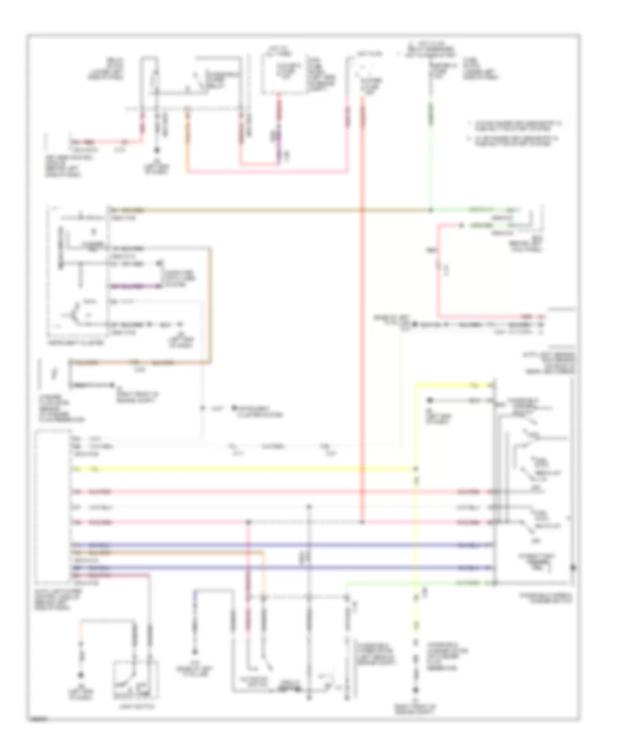
Instrument Illumination Wiring Diagram for Mazda 6 i Grand Touring 2011
List of elements for Instrument Illumination Wiring Diagram for Mazda 6 i Grand Touring 2011:
- (base of left "a" pillar) g14
- (behind left kick panel) bcm
- (behind left side of dash) (w/ advanced keyless entry & push button start system) keyless control module
- (w/ advanced keyless entry & push button start system) push button start illumination
- (w/ atx) selector illumination
- (w/ rear vent) rear fan switch
- 0740-101a
- 0740-201a
- 0914-401d
- 0918-101b
- 0920-201a
- 0920-301a
- 0922-101b
- 0922-201
- 0922-202
- 0940-01c
- 0940-01d
- Audio unit/car navigation unit (lower center of dash)
- Auto
- Auto light/wiper control module (behind left side of dash)
- Automatic a/c
- Bose audio
- Bsm off switch (w/ bsm)
- C-34
- C-55
- Climate control module (lower center of dash)
- Clock spring (in steering column)
- Coil antenna (behind left side of dash)
- Computer data lines system
- Cruise control switch
- Dimmer cancel switch
- Down light
- Except bose audio
- Fuse block (under left side of dash)
- G8 (left end of dash)
- Glove compartment light
- H/l
- Hazard warning switch illumination
- Hot at all times
- Hot in run or start
- Illumi fuse 7.5a
- Illumi ind
- Info switch (w/ info switch)
- Information display
- Instrument cluster
- Left seat warmer switch illumination (w/ seat warmer)
- Light switch
- Lines system computer data
- Manual a/c
- Meter ig fuse 15a
- Microcomputer
- Nca
- Off
- Red
- Right seat warmer switch illumination (w/ seat warmer)
- Room fuse 15a
- Steering switch
- Tcs off/dsc off/ info & bsm off switch illuminations
- Tns
- Tns ind
- Trunk lid opener switch illumination (vehicle interior)
- W/ advanced keyless entry & push button start system
- W/ auto light system
- W/o advanced keyless entry & push button start system
MEMORY SYSTEMS
Memory Systems Wiring Diagram (1 of 2) for Mazda 6 i Grand Touring 2011
List of elements for Memory Systems Wiring Diagram (1 of 2) for Mazda 6 i Grand Touring 2011:
- (left end of dash) g8
- (under right front passenger's seat) g16
- 0913-201a
- 0913-201b
- 0913-201c
- 0913-206
- 0922-101b
- Back
- C-06
- C-10
- C-24
- Computer data lines system
- Down
- Front
- Front tilt motor
- Front tilt motor/rear tilt motor/slide motor (tilt motor: under driver's seat) (slide motor: under front passenger's seat)
- Front tilt sensor
- Hot at all times
- Instrument cluster
- Main fuse block (left side of engine compt)
- Micro computer
- Nca
- P seat (d) fuse 30a
- Position memory control module (under driver's seat)
- Position sensor (under rear of driver's seat)
- Rear tilt motor
- Rear tilt sensor
- Recliner motor
- Recliner sensor
- Reclining motor & position sensor (in driver's seat back)
- Red
- Red a
- Slide motor
- Slide sensor
- Solid state
Memory Systems Wiring Diagram (2 of 2) for Mazda 6 i Grand Touring 2011
List of elements for Memory Systems Wiring Diagram (2 of 2) for Mazda 6 i Grand Touring 2011:
- 0940-01d
- 0940-01f
- 0940-01g
- 0940-01h
- Backward
- Bcm (behind left kick panel)
- Door locks system
- Down
- Forward
- Fuse block (under left side of dash)
- Hot at all times
- Hot in on or start
- Lift switch
- Memory 1
- Memory 2
- Memory 3
- Meter ig fuse 15a
- Nca
- Position memory switch
- Power seat switch
- Power windows system
- Recliner switch
- Room fuse 15a
- Set
- Slide switch
- Tilt switch
NAVIGATION
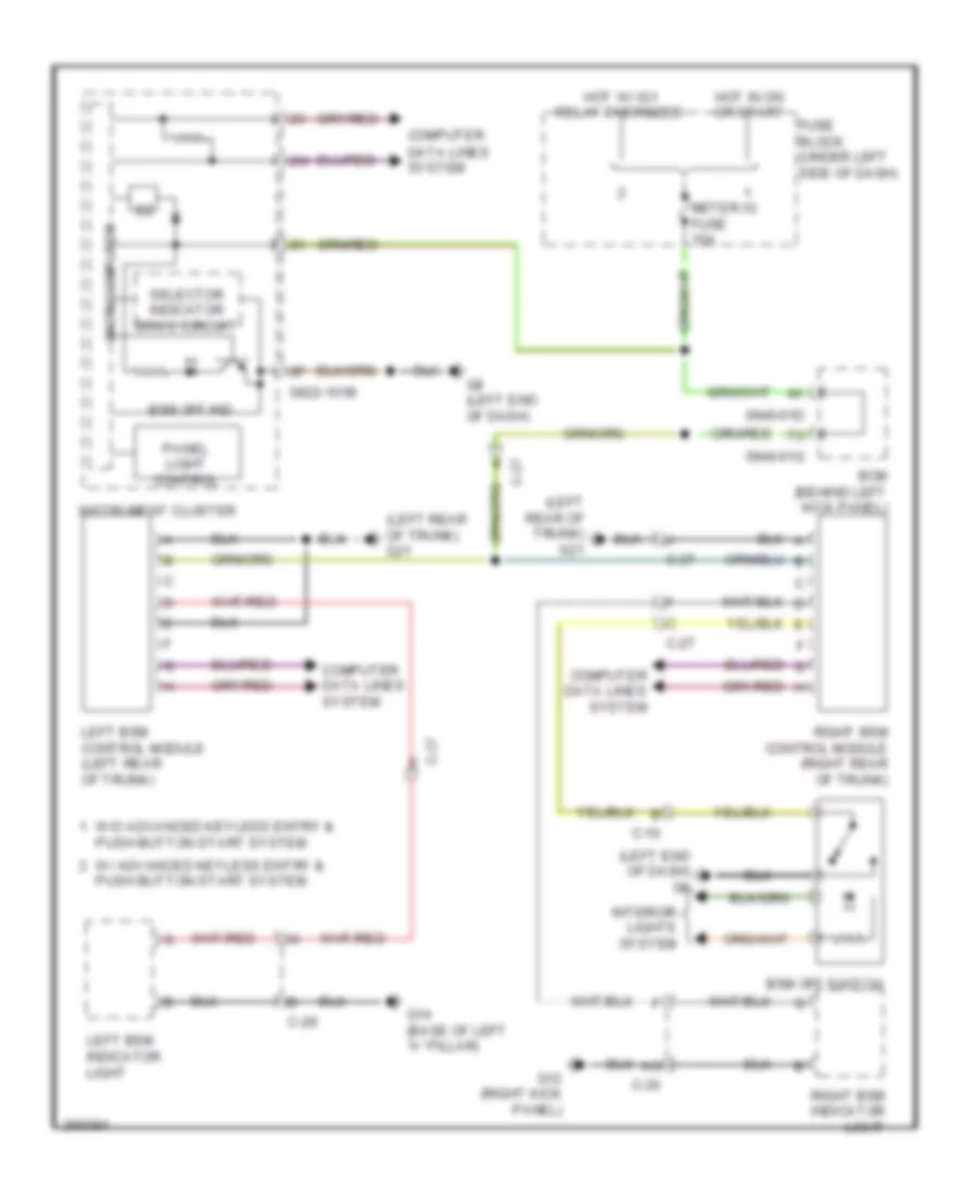
Blind Spot Monitoring Wiring Diagram for Mazda 6 i Grand Touring 2011
List of elements for Blind Spot Monitoring Wiring Diagram for Mazda 6 i Grand Touring 2011:
- (left end of dash) g8
- (left rear of trunk) g21
- 0922-101b
- 0940-01d
- 0940-01g
- Bcm (behind left kick panel)
- Bsm off ind
- Bsm off switch
- C-10
- C-27
- C-29
- C-30
- Computer
- Computer data lines system
- Data lines system
- Fuse block (under left side of dash)
- G12 (right kick panel)
- G14 (base of left "a" pillar)
- G8 (left end of dash)
- Hot in on or start
- Hot w/ ig1 relay energized
- Instrument cluster
- Interior lights system
- Left bsm control module (left rear of trunk)
- Left bsm indicator light
- Meter ig fuse 15a
- Microcomputer
- Panel light control
- Right bsm control module (right rear of trunk)
- Right bsm indicator light
- Selector indicator drive circuit
- W/ advanced keyless entry & push button start system
- W/o advanced keyless entry & push button start system
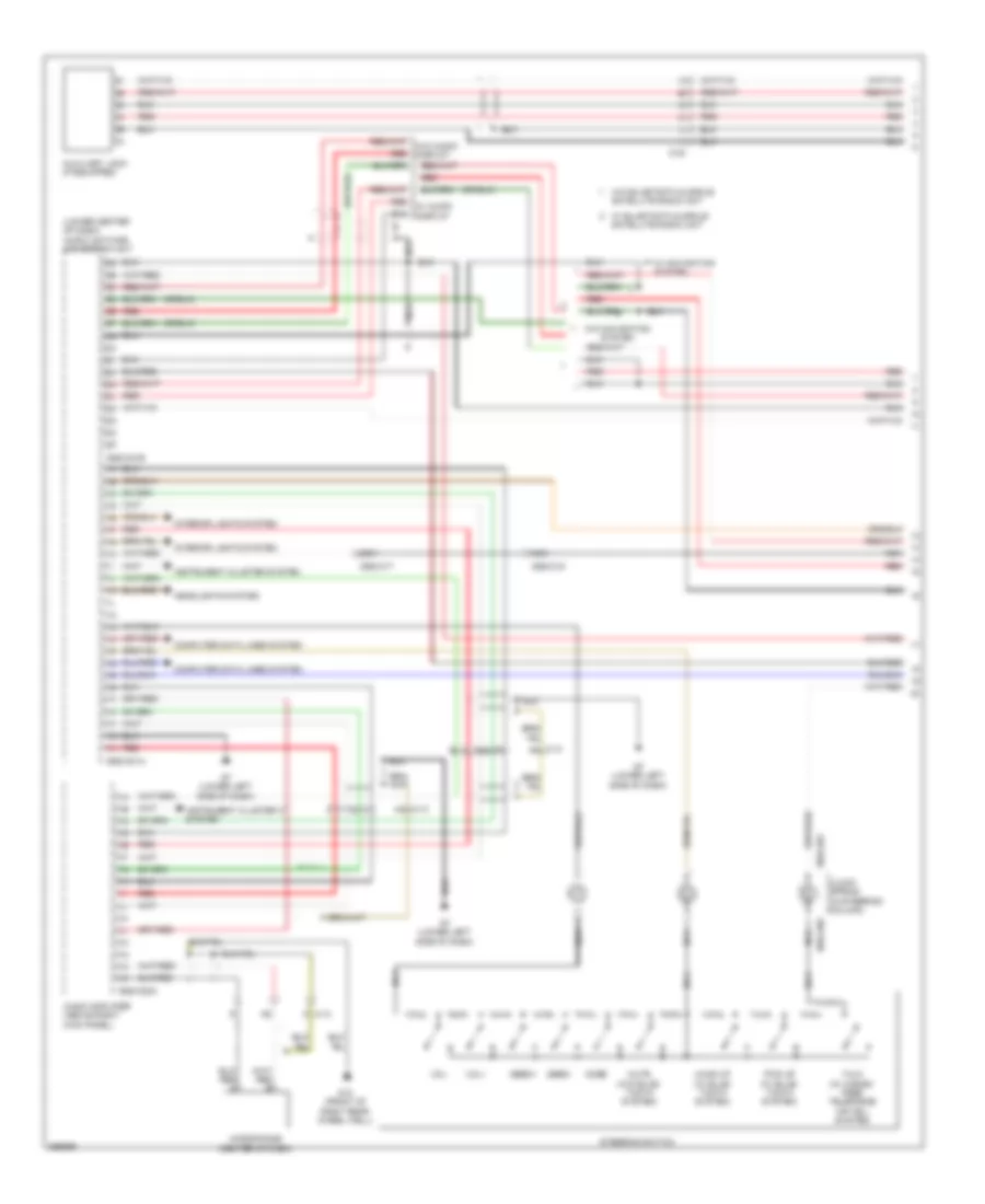
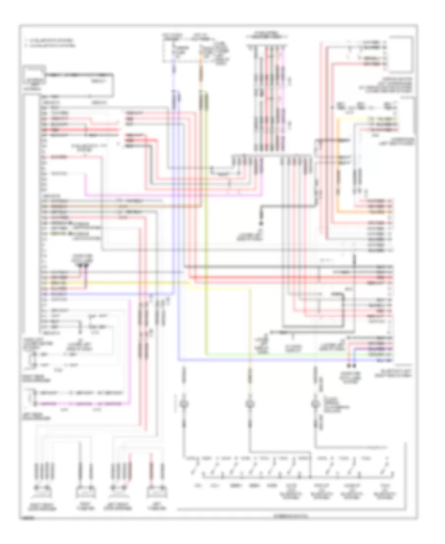
Navigation Wiring Diagram, with Bose (1 of 3) for Mazda 6 i Grand Touring 2011
List of elements for Navigation Wiring Diagram, with Bose (1 of 3) for Mazda 6 i Grand Touring 2011:
- (lower center of dash) audio unit/car- navigation unit
- 0920-301a
- 0920-301b
- 0920-302a
- 0920-317
- 0920-318
- 0922-201
- 0922-202
- Aa c-13
- Audio amplifier (above right kick panel)
- Auxiliary jack (if equipped)
- C-13 an
- C-23
- Clock spring (in steering column)
- Computer data lines system
- G13 (front of right rear wheel well)
- G7 (lower left side of dash)
- Headlights system
- Instrument cluster system
- Interior lights system
- M c-13
- Microphone (center of dash)
- Mode
- Nca
- Red
- Seek+
- Seek-
- Steering switch
- Talk (w/ hands- free telephone (hf/tel) system)
- Vol+
- Vol-
- W/ audio display
- W/ navigation system
- W/o audio display
- W/o navigation system
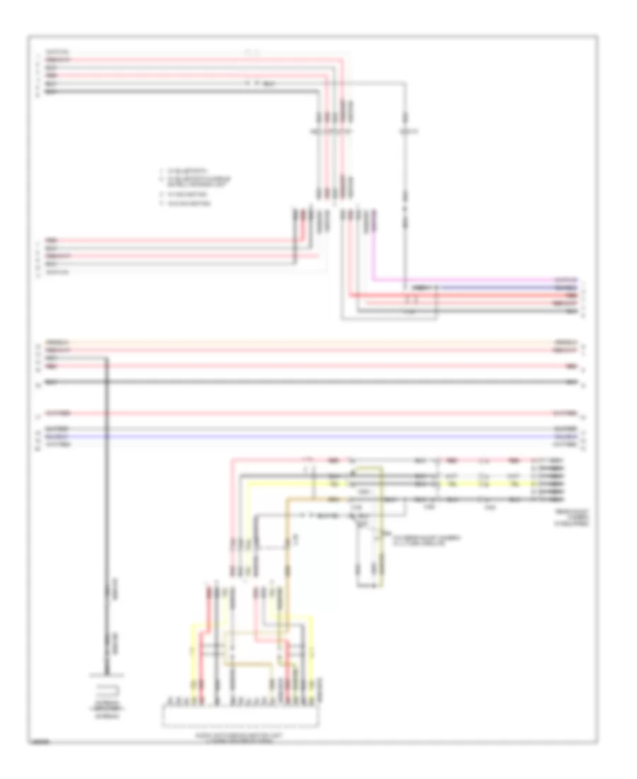
Navigation Wiring Diagram, with Bose (2 of 3) for Mazda 6 i Grand Touring 2011
List of elements for Navigation Wiring Diagram, with Bose (2 of 3) for Mazda 6 i Grand Touring 2011:
- 0920-301d
- 0920-301e
- 0920-319
- 0920-320
- Antenna
- Antenna amplifier
- Audio unit/car-navigation unit (lower center of dash)
- C-10
- C-35
- C-61
- C-62
- C-63
- N c-10
- Nca
- Rear mount camera (if equipped)
- Red
- W/ navigation
- W/o navigation
- W/o rear mount camera/ w/ u-turn circuits
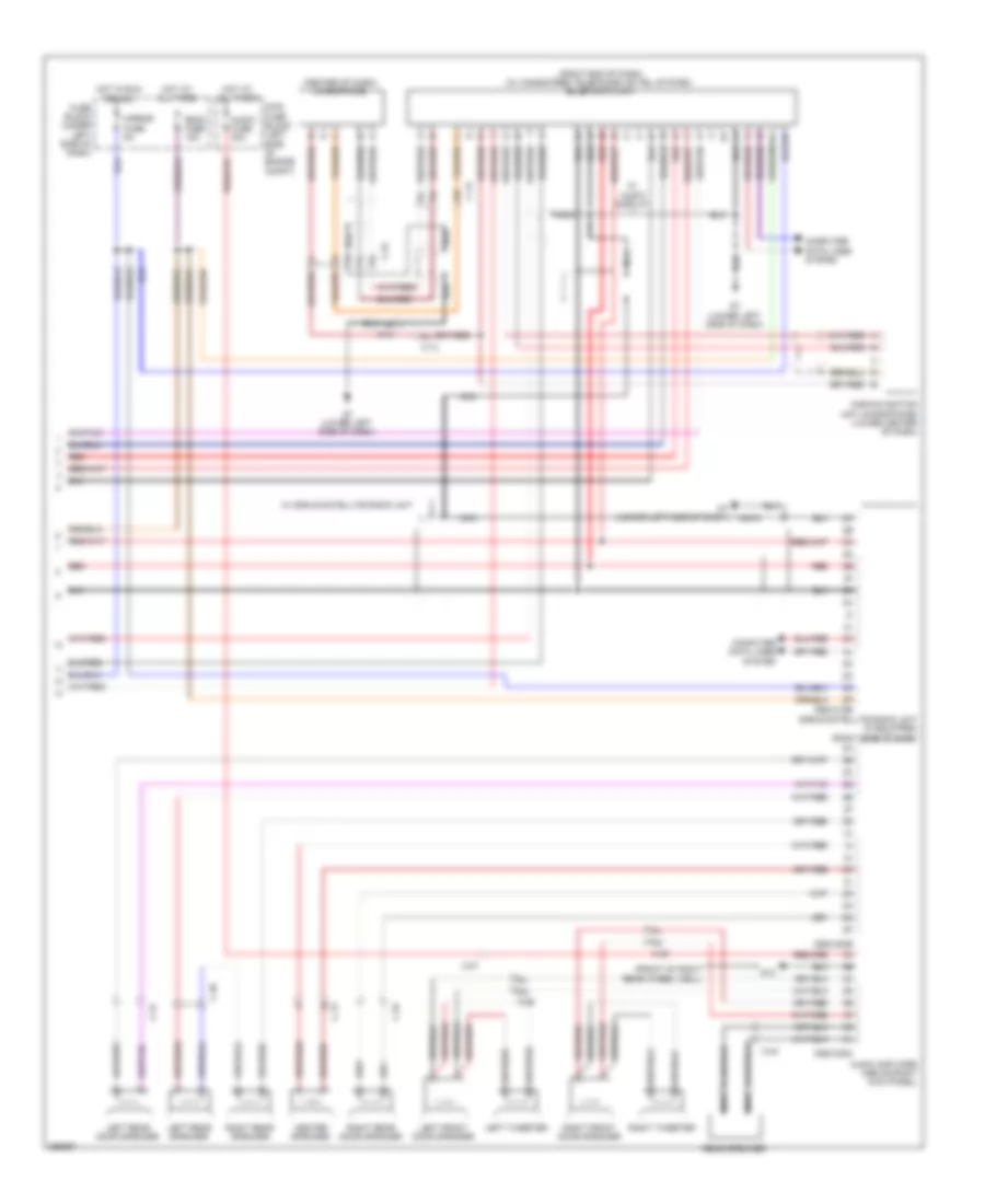
Navigation Wiring Diagram, with Bose (3 of 3) for Mazda 6 i Grand Touring 2011
List of elements for Navigation Wiring Diagram, with Bose (3 of 3) for Mazda 6 i Grand Touring 2011:
- (center of dash) microphone
- (front of right rear wheel well)
- 0920-302b
- 0920-302c
- 0920-315b
- Audio amplifier (above right kick panel)
- Audio fuse 30a
- C-07
- C-13
- C-22
- C-29
- C-30
- C-31
- C-32
- C-40
- Car-navigation unit (microphone) (lower center of dash)
- Center speaker
- Computer data lines system
- Fuse block (under left side of dash)
- G13
- G7 (lower left side of dash)
- Hot at all times
- Hot in run or acc
- Left front door speaker
- Left rear door speaker
- Left rear speaker
- Left tweeter
- Main fuse block (left side of engine compt)
- Mirror fuse 5a
- Nca
- Rear speaker
- Red
- Right front door speaker
- Right rear door speaker
- Right rear speaker
- Right tweeter
- Room fuse 15a
- Sirius satellite radio unit (if equipped) (right side of dash)
- W/ audio display
- W/ sirius satellite radio unit
Navigation Wiring Diagram, without Bose for Mazda 6 i Grand Touring 2011
List of elements for Navigation Wiring Diagram, without Bose for Mazda 6 i Grand Touring 2011:
- (if equipped) auxiliary jack
- 0920-201a
- 0920-201b
- 0920-201c
- 0920-210
- 0920-211
- 0922-201
- 0922-202
- Antenna
- Antenna amp
- Audio unit (lower center of dash)
- C-10
- C-13
- C-22
- C-23
- C-29
- C-30
- C-31
- C-32
- Car-navigation unit (microphone) (w/ car-navigation system) (lower center of dash)
- Clock spring (in steering column)
- Computer data lines system
- Fuse block (under left side of dash)
- G7 (lower left side of dash)
- Hot at all times
- Hot in run or acc
- Interior lights system
- Left front door speaker
- Left rear door speaker
- Left tweeter
- Microphone (left end of dash)
- Mirror fuse 5a
- Mode
- Nca
- Red
- Red c
- Right front door speaker
- Right rear door speaker
- Right tweeter
- Room fuse 15a
- Seek+
- Seek-
- Steering switch
- Vol+
- Vol-
- W/ audio display
POWER DISTRIBUTION
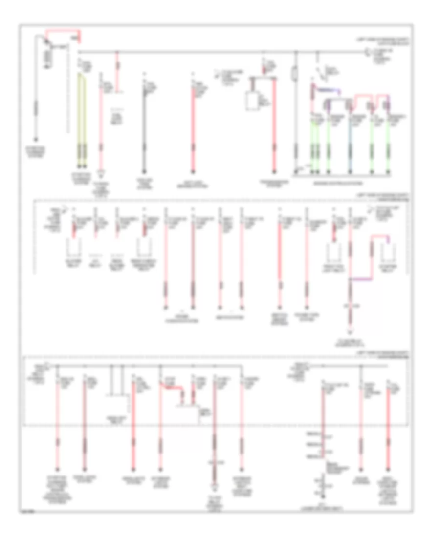
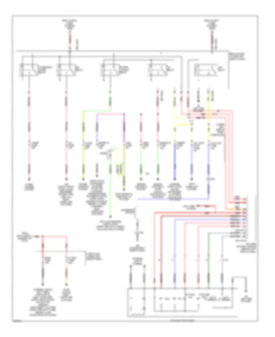
Power Distribution Wiring Diagram, with Advanced Keyless Entry & Start System (1 of 2) for Mazda 6 i Grand Touring 2011
List of elements for Power Distribution Wiring Diagram, with Advanced Keyless Entry & Start System (1 of 2) for Mazda 6 i Grand Touring 2011:
- (left side of engine compt) main fuse block
- 2.5l
- 2.5l red
- 3.7l
- A c-23
- A/c fuse 10a
- A/c relay
- Abs motor fuse 60a
- An c-05
- Anti-lock brakes system
- Ap c-05
- At main relay
- Audio fuse (w/ bose) 30a
- Battery
- Blower 2 fuse 15a
- Blower fuse 40a
- Blower relay
- Body computer, interior lights & exterior lights systems
- Btn fuse 30a
- C-07
- C-23 k
- Cooling fans system
- Defog fuse 40a
- Door locks system
- Drl fuse (w/ drl) 20a
- Eng +b fuse 10a
- Engine 2 fuse 15a
- Engine controls system
- Engine fuse 10a
- Engine fuse 20a
- Escl fuse 10a
- Exterior lights & body computer systems
- Exterior lights system
- Fan fuse 60a
- Fog fuse 15a
- From a main relay (diagram 1 of 2)
- From b abs motor fuse (diagram 1 of 2)
- From ig key2 c fuse (diagram 1 of 2)
- Front fog light relay
- Fuel pump relay
- G17 (under driver's seat)
- Hazard fuse 10a
- Headlight relay
- Headlights system
- Horn fuse 15a
- Horn relay
- Ig fuse 20a
- Ig key1 fuse 40a
- Ig key2 fuse 40a
- Main fuse 125a
- Main relay
- P outlet (r) fuse 15a
- P seat (d) fuse 30a
- P seat (p) fuse 30a
- P wind (d) fuse 40a
- P wind (p) fuse 25a
- Pcm fuse 10a
- Power tops system
- Power windows system
- Rear accessory socket
- Rear blower relay
- Rear window defroster relay
- Red
- Seat heat fuse 20a
- Seats & memory systems
- Seats system
- Sound systems
- Starter relay
- Starting/ charging system
- Starting/ charging, anti-theft, engine controls & transmissions systems
- Stop fuse 10a
- Sunroof fuse 15a
- Tail fuse 15a
- Tcm fuse 20a
- To acc relay (diagram 2 of 2)
- To blower fuse (diagram 1 of 2)
- To eng +b fuse (diagram 1 of 2)
- To ig2 relay (diagram 2 of 2)
- To p outlet (r) fuse (diagram 1 of 2)
- To room fuse (diagram 2 of 2)
- Transmissions system
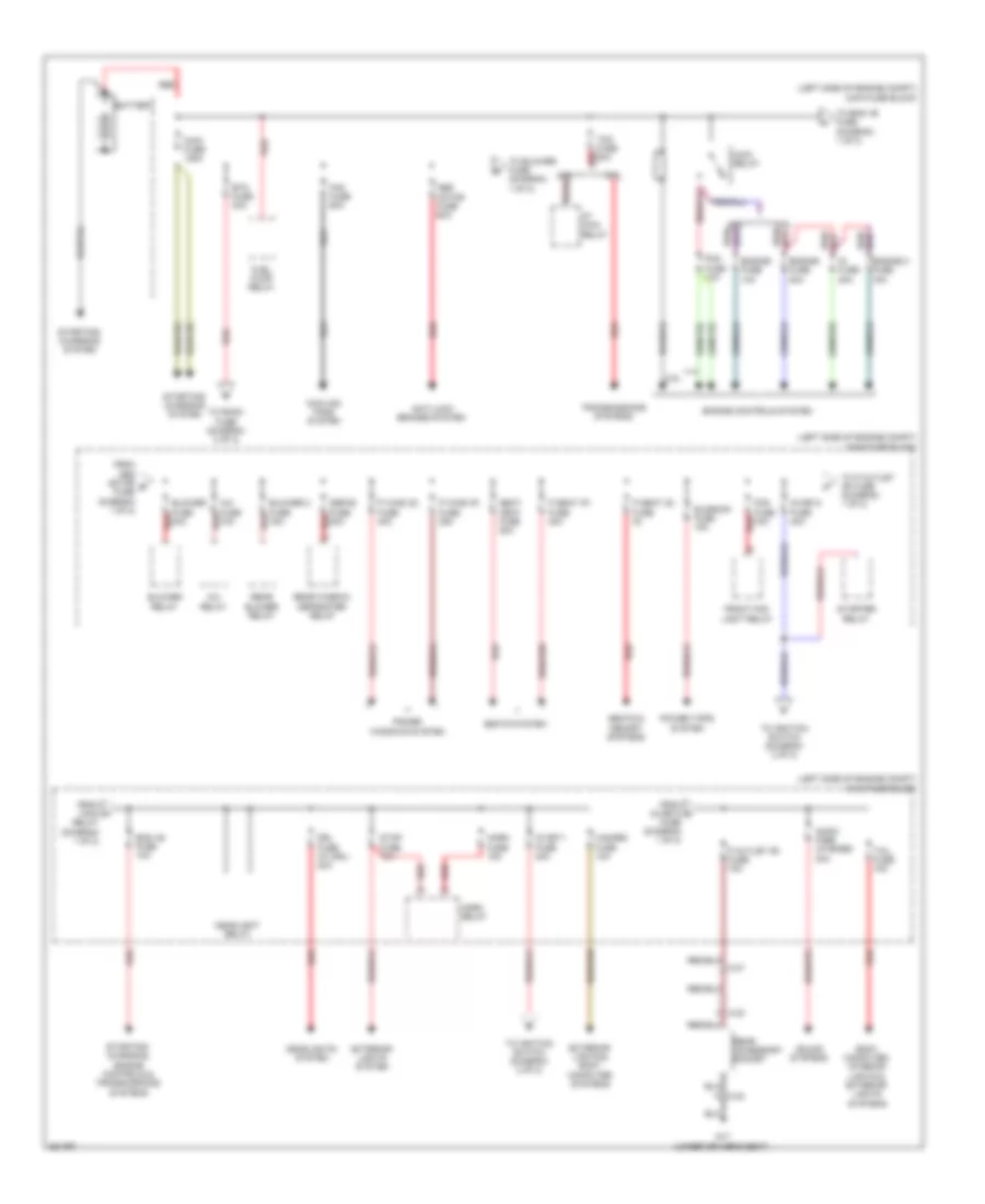
Power Distribution Wiring Diagram, with Advanced Keyless Entry & Start System (2 of 2) for Mazda 6 i Grand Touring 2011
List of elements for Power Distribution Wiring Diagram, with Advanced Keyless Entry & Start System (2 of 2) for Mazda 6 i Grand Touring 2011:
- (under left side of dash) fuse block
- 0914-401b
- 0914-401d
- 0921-201a
- 0921-201b
- 2.5l
- A/c fuse 10a
- Acc
- Acc relay
- Accessory socket
- Air conditioning, door locks, defogger, power tops, seats & body computer systems
- Anti-lock brakes, door locks, computer data lines & cooling fans systems
- Anti-theft system
- Auto return
- C c-55
- C-10
- C-13
- D lock fuse 25a
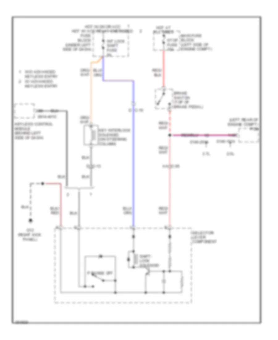
- Diode
- Door locks & body computer systems
- Engine controls system
- Engine controls, door locks & cooling fans systems
- Engine ig fuse 15a
- From btn fuse (diagram 1 of 2)
- From ig key1 fuse (diagram 1 of 2)
- From ig key2 fuse (diagram 1 of 2)
- Fuse block (under left side of dash)
- G8 (left end of dash)
- G9 (lower right side of dash)
- Headlights, instrument cluster, starting/ charging, transmissions, exterior lights, door locks, engine controls, memory, wiper/ washer & body computer systems
- Hego fuse 5a
- Ig1 relay
- Ig2 relay
- Int lock/ shift fuse 5a
- Interior lights system
- Interior lights, anti-theft, headlights, body computer, door locks, sound, navigation, mirrors, instrument cluster, computer data lines, memory & air conditioning systems
- Keyless control module (behind left side of dash)
- Meter ig fuse 15a
- Mirror fuse 5a
- Mirrors, door locks, sound, instrument cluster & navigation systems
- P outlet fuse 15a
- P wind fuse 30a
- Power window relay
- Power windows system
- Push button start
- Red
- Relay block (lower left side of dash)
- Room fuse 15a
- Sas fuse 5a
- Shift interlock system
- Status (ur)
- Status (yg)
- Windshield wiper relay
- Wiper fuse 25a
- Wiper/ washer system
Power Distribution Wiring Diagram, without Advanced Keyless Entry & Start System (1 of 2) for Mazda 6 i Grand Touring 2011
List of elements for Power Distribution Wiring Diagram, without Advanced Keyless Entry & Start System (1 of 2) for Mazda 6 i Grand Touring 2011:
- (left side of engine compt) main fuse block
- 2.5l
- 2.5l red
- 3.7l
- A c-23
- A/c fuse 10a
- A/c relay
- Abs motor fuse 60a
- Anti-lock brakes system
- At main relay
- Audio fuse (w/ bose) 30a
- Battery
- Blower 2 fuse 15a
- Blower fuse 40a
- Blower relay
- Body computer, interior lights & exterior lights systems
- Btn fuse 30a
- C-07
- C-23
- Cooling fans system
- Defog fuse 40a
- Drl fuse (w/ drl) 20a
- Eng +b fuse 10a
- Engine 2 fuse 15a
- Engine controls system
- Engine fuse 10a
- Engine fuse 20a
- Exterior lights & body computer systems
- Exterior lights system
- Fan fuse 60a
- Fog fuse 15a
- From abs motor b fuse (diagram 1 of 2)
- From ig key2 c fuse (diagram 1 of 2)
- From main a
- Front fog light relay
- Fuel pump relay
- G17 (under driver's seat)
- Hazard fuse 10a
- Headlight relay
- Headlights system
- Horn fuse 15a
- Horn relay
- Ig fuse 20a
- Ig key1 fuse 40a
- Ig key2 fuse 40a
- Main fuse 125a
- Main relay
- P outlet (r) fuse 15a
- P seat (d) fuse
- P seat (p) fuse 30a
- P wind (d) fuse 40a
- P wind (p) fuse 25a
- Pcm fuse 10a
- Power tops system
- Power windows system
- Rear accessory socket
- Rear blower relay
- Rear window defroster relay
- Red
- Red d
- Relay (diagram 1 of 2)
- Seat heat fuse 20a
- Seats & memory systems
- Seats system
- Sound systems
- Starter relay
- Starting/ charging system
- Starting/ charging, engine controls & transmissions systems
- Stop fuse 10a
- Sunroof fuse 15a
- Tail fuse 15a
- Tcm fuse 20a
- To blower fuse (diagram 1 of 2)
- To eng +b fuse (diagram 1 of 2)
- To ignition switch (diagram 2 of 2)
- To p outlet (r) fuse (diagram 1 of 2)
- To room fuse (diagram 2 of 2)
- Transmissions systems
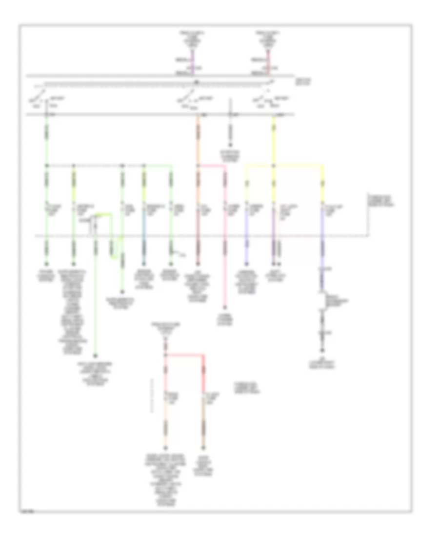
Power Distribution Wiring Diagram, without Advanced Keyless Entry & Start System (2 of 2) for Mazda 6 i Grand Touring 2011
List of elements for Power Distribution Wiring Diagram, without Advanced Keyless Entry & Start System (2 of 2) for Mazda 6 i Grand Touring 2011:
- 2.5l
- A/c fuse 10a
- Acc
- Air conditioning, defogger, power tops, seats & body computer systems
- An c-05
- Anti-lock brakes, door locks, computer data lines & cooling fans systems
- Ap c-05
- C-55 c
- D lock fuse 25a
- Diode
- Door locks & body computer systems
- Door locks, sound, mirrors, navigation, instrument cluster, computer data lines, air conditioning, memory, interior lights, anti-theft, headlights & body computer systems
- Engine controls & cooling fans systems
- Engine controls system
- Engine ig fuse 15a
- From btn fuse (diagram 1 of 2)
- From ig key1 fuse (diagram 1 of 2)
- From ig key2 fuse (diagram 1 of 2)
- Front accessory socket
- Fuse block (under left side of dash)
- G9 (lower right side of dash)
- Hego fuse 5a
- Ig1
- Ig2
- Ignition switch
- Int lock/ shift fuse 5a
- Meter ig fuse 15a
- Mirror fuse 5a
- Mirrors, navigation, sound & instrument cluster systems
- Off
- P outlet fuse 15a
- P wind fuse 30a
- Power windows system
- Red
- Room fuse 15a
- Run
- Sas fuse 5a
- Shift interlock system
- Start
- Starting/ charging system
- Wiper fuse 25a
- Wiper/ washer system
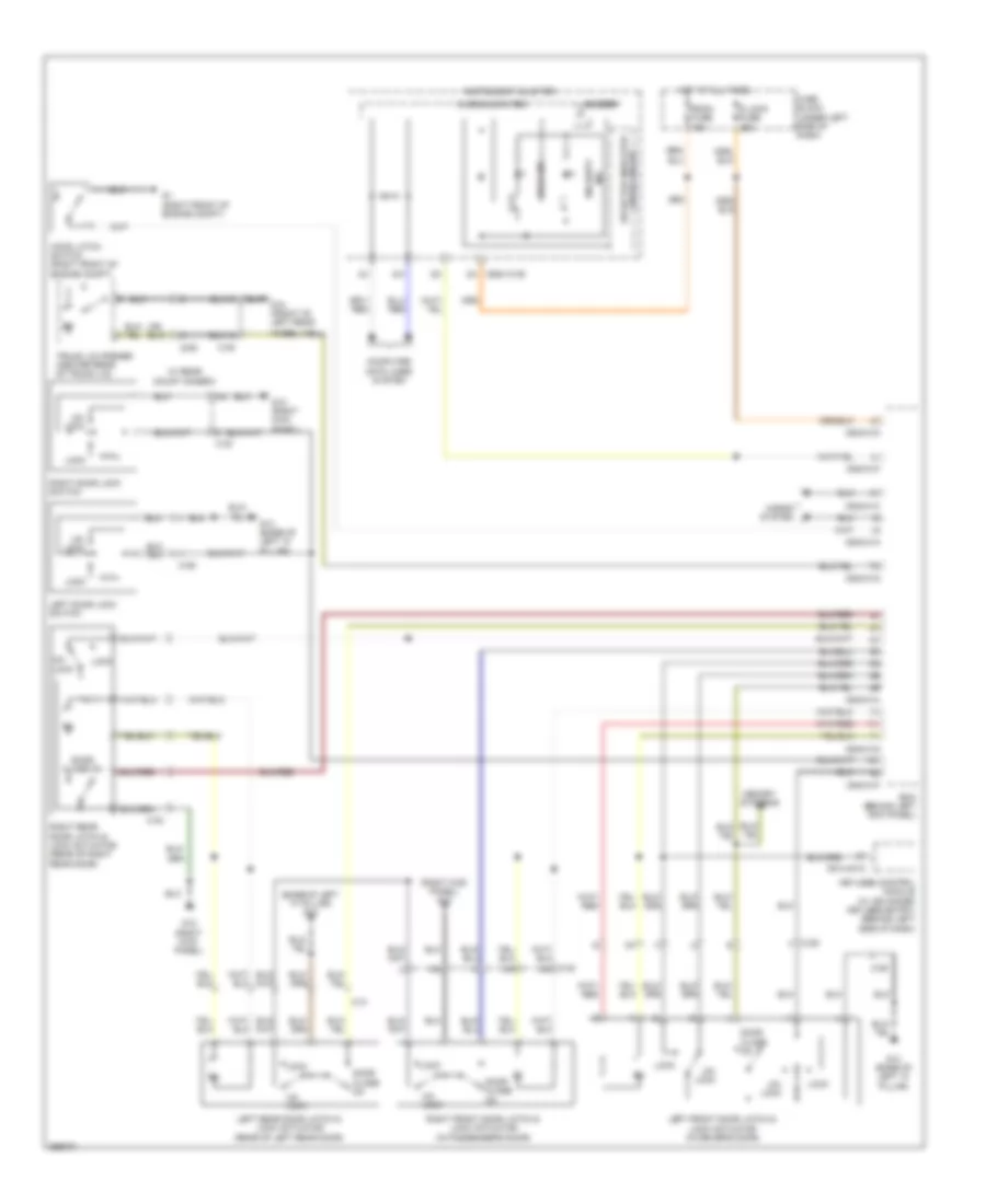
POWER DOOR LOCKS
Door Lock Wiring Diagram for Mazda 6 i Grand Touring 2011
List of elements for Door Lock Wiring Diagram for Mazda 6 i Grand Touring 2011:
- (base of left "a" pillar) g14
- (right kick panel) g12
- 0914-401c
- 0940-01a
- 0940-01c
- 0940-01d
- 0940-01f
- 0940-01g
- 0940-01h
- 2h 0922-101b
- Bcm (behind left kick panel)
- Buzzer
- C-29
- C-29 t
- C-30
- C-30 am
- C-31
- C-32
- C-35
- C-62
- Computer data lines system
- D lock fuse 25a
- Door close on
- Door ind
- Fuse block (under left side of dash)
- G1 (right front of engine compt)
- G12 (right kick panel)
- G14 (base of left "a" pillar)
- G18 (front of left rear
- Hood latch switch (right front of engine compt)
- Horns system
- Hot at all times
- Instrument cluster
- Keyless control module (w/ advanced keyless entry) (behind left side of dash)
- Left door lock switch
- Left front door latch & lock actuator (in driver's door)
- Left rear door latch & lock actuator (rear of left rear door)
- Lock
- Memory systems
- Microcomputer
- Right door lock switch
- Right front door latch & lock actuator (in passenger's door)
- Right rear door latch & lock actuator (rear of right rear door)
- Room fuse 15a
- Security ind
- Selector indicator drive circuit
- Trunk lid opener (center rear of trunk lid)
- Un- lock
- W/ rear mount camera
- Wheel well)
Keyless Entry Wiring Diagram (1 of 3) for Mazda 6 i Grand Touring 2011
List of elements for Keyless Entry Wiring Diagram (1 of 3) for Mazda 6 i Grand Touring 2011:
- 0914-401a
- 0914-401b
- 0914-401d
- 4aa
- Anti-theft system
- Brake switch (top of brake pedal)
- C-06
- C-10
- C-10 l
- C-11
- C-13
- Computer data lines system
- E c-11
- Eng +b fuse 10a
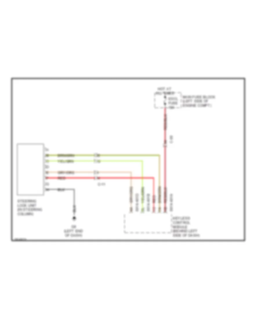
- Escl fuse 10a
- G14 (base of left "a" pillar)
- G8 (left end of dash)
- Hot at all times
- Interior lights system
- Keyless control module (w/ advanced keyless entry & push button start system) (behind left side of dash)
- Keyless receiver/ tpms control module (w/ advanced keyless entry & push button start system) (behind right side of dash)
- Main fuse block (left side of engine compt)
- Red
- Starting/ charging system
- Steering lock unit (on steering column)
- Stop fuse 10a
Keyless Entry Wiring Diagram (2 of 3) for Mazda 6 i Grand Touring 2011
List of elements for Keyless Entry Wiring Diagram (2 of 3) for Mazda 6 i Grand Touring 2011:
- (behind right side of dash) (w/o advanced keyless entry & push button start system) keyless receiver/ tpms control module
- 0921-201a
- 0921-201b
- A/c fuse 10a
- Acc relay
- C-13
- C-27 l
- Engine ig fuse 15a
- Fuse block (under left side of dash)
- G8 (left end of dash)
- H c-06
- Hot at all times
- Ig1 relay
- Ig2 relay
- Keyless switch smart (on steering column)
- Meter ig fuse 15a
- Mirror fuse 5a
- Rear exterior keyless antenna (behind center of rear bumper)
- Rear interior keyless antenna (center front of trunk lid)
- Red
- Relay block (lower left side of dash)
- Room fuse 15a
- Sas fuse 5a
- W/ advanced keyless entry & push button start system
- W/o advanced keyless entry & push button start system
Keyless Entry Wiring Diagram (3 of 3) for Mazda 6 i Grand Touring 2011
List of elements for Keyless Entry Wiring Diagram (3 of 3) for Mazda 6 i Grand Touring 2011:
- (left front of engine compt) g2
- 0914-401c
- 0922-101b
- 0940-01c
- 0940-01d
- 0940-01f
- 0940-01g
- 0940-01h
- 2.5l
- 3.7l
- 3aa
- 3ab
- 3ac
- 3ad
- A c-10
- Ac c-10
- Acc ind
- Anti- theft system
- Auto rtn sw
- B c-45
- Bcm (behind left kick panel)
- C-06
- C-07
- C-10
- C-13 l
- C-23 h
- C-29
- C-46
- Center interior keyless antenna (under center console)
- Computer data lines system
- Cruise control system
- E c-30
- Front interior keyless antenna (under front of center console)
- G12 (right kick panel)
- G14 (base of left "a" pillar)
- G5 (base of left "a" pillar)
- G8 (left end of dash)
- Instrument cluster
- Key ind (green)
- Key ind (red)
- Keyless beeper (base of left "a" pillar)
- Keyless control module (behind left side of dash)
- L c-29
- Left front exterior keyless antenna
- Left front outer handle
- Microcomputer
- On ind
- Push button start
- Red
- Request switch
- Right front exterior keyless antenna
- Right front outer handle
- Selector indicator drive circuit
- Shift interlock system
- Status (ur) ind
- Status (yg) ind
- Touch sensor
- Trunk, tailgate, fuel doors system
- W/ advanced keyless entry & push button start system
POWER MIRRORS
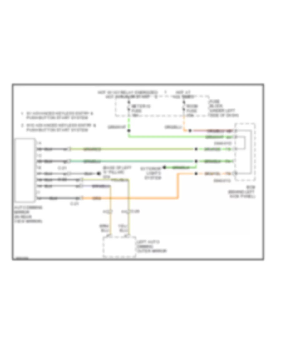
Auto Dimming Mirror Wiring Diagram, with Auto Dimming Outer Mirror for Mazda 6 i Grand Touring 2011
List of elements for Auto Dimming Mirror Wiring Diagram, with Auto Dimming Outer Mirror for Mazda 6 i Grand Touring 2011:
- (base of left "a" pillar) g14
- 0940-01d
- 0940-01g
- Auto dimming mirror (in rear view mirror)
- Bcm (behind left kick panel)
- C-21
- C-22
- C-29 aa
- Exterior lights system
- Fuse block (under left side of dash)
- Hot at all times
- Hot w/ ig1 relay energized hot in run or start
- Left auto dimming outer mirror
- Meter ig fuse 15a
- Push button start system
- Room fuse 15a
- W/ advanced keyless entry &
- W/o advanced keyless entry & push button start system
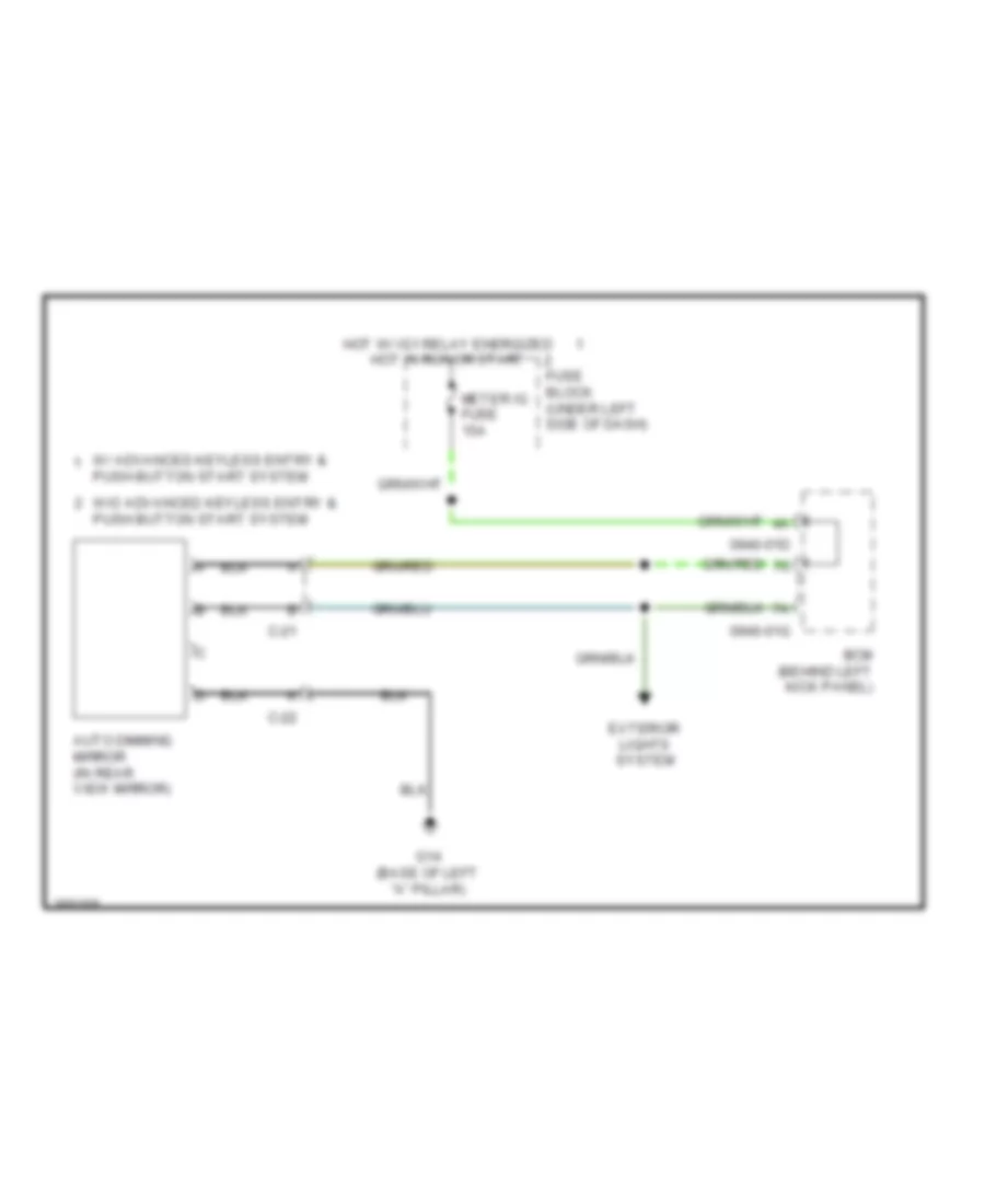
Auto Dimming Mirror Wiring Diagram, without Auto Dimming Outer Mirror for Mazda 6 i Grand Touring 2011
List of elements for Auto Dimming Mirror Wiring Diagram, without Auto Dimming Outer Mirror for Mazda 6 i Grand Touring 2011:
- 0940-01d
- 0940-01g
- Auto dimming mirror (in rear view mirror)
- Bcm (behind left kick panel)
- C-21
- C-22
- Exterior lights system
- Fuse block (under left side of dash)
- G14 (base of left "a" pillar)
- Hot w/ ig1 relay energized hot in run or start
- Meter ig fuse 15a
- Push button start system
- W/ advanced keyless entry &
- W/o advanced keyless entry & push button start system
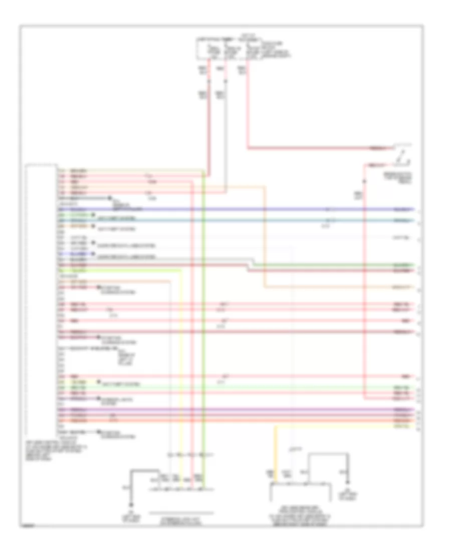
Power Mirror Wiring Diagram for Mazda 6 i Grand Touring 2011
List of elements for Power Mirror Wiring Diagram for Mazda 6 i Grand Touring 2011:
- 0912-301
- 0912-801a
- 0912-801a 1m
- 0912-901a
- 0912-901a 1n
- Auto-open/close function for driver side window
- Auto-open/close function for front window
- C-10
- C-29
- Down
- Fuse block (under left side of dash)
- G14 (base of left "a" pillar)
- Hot in acc or run
- Left
- Left power outer mirror (at left mirror)
- Left retractable outer mirror (if equipped)
- M c-30
- Mirror fuse 5a
- P/w cm
- Power outer mirror switch/ retractable outer mirror switch
- Retract
- Return
- Right
- Right power outer mirror (at right mirror)
- Right retractable outer mirror (if equipped)
- W/ retractable outer mirror
- W/o retractable outer mirror
POWER SEATS
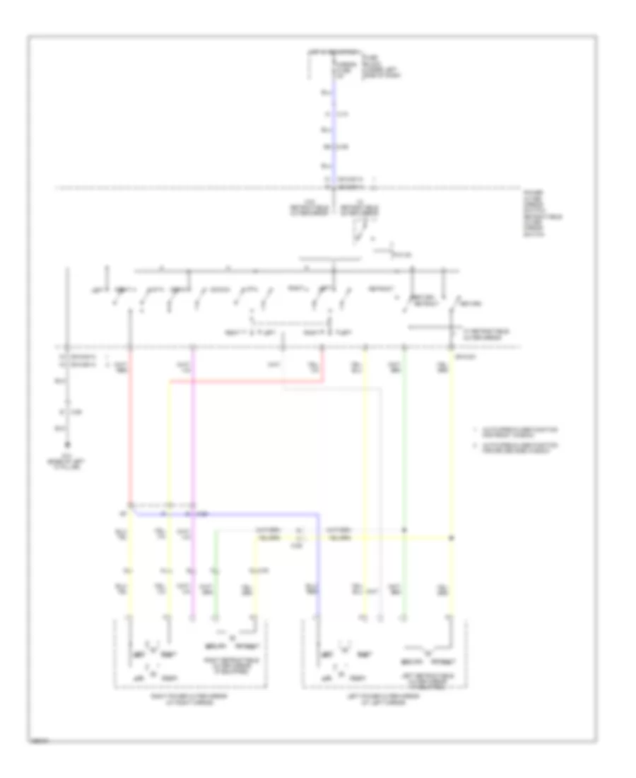
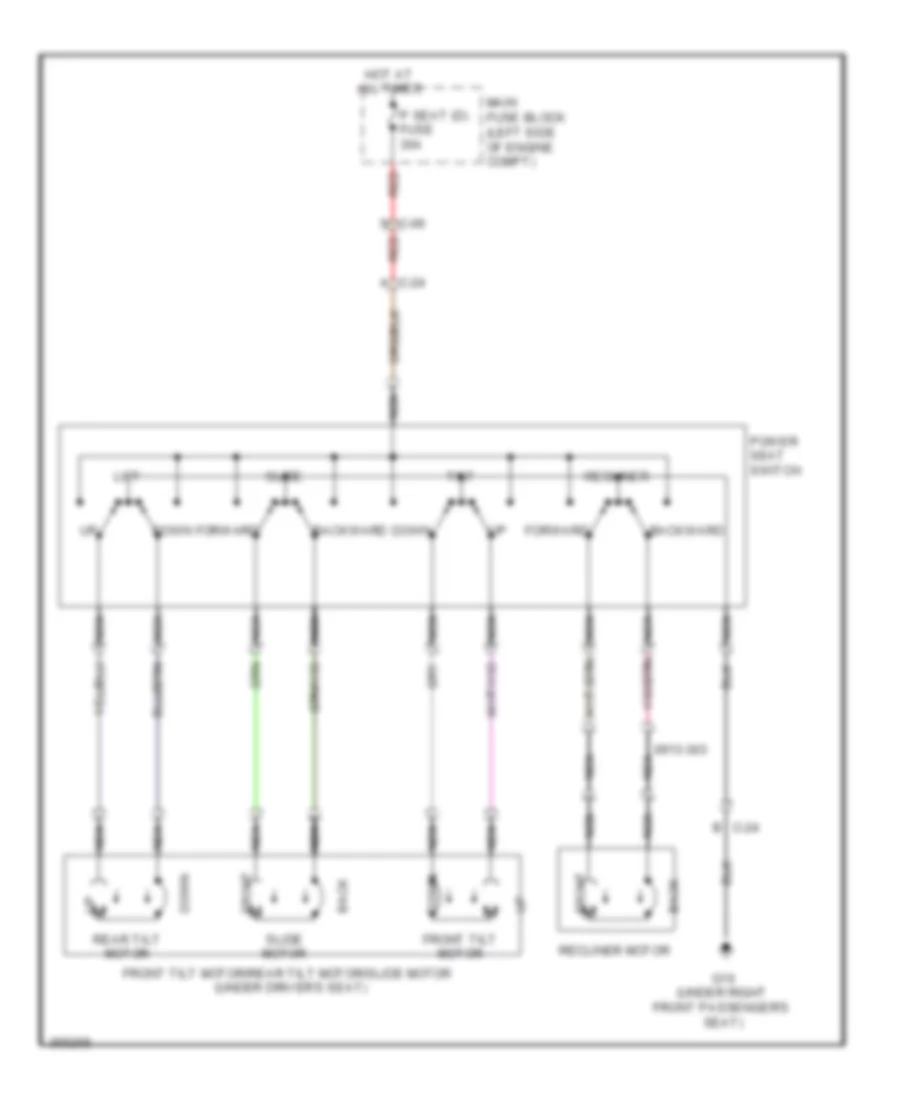
Driver Power Seat Wiring Diagram for Mazda 6 i Grand Touring 2011
List of elements for Driver Power Seat Wiring Diagram for Mazda 6 i Grand Touring 2011:
- 0913-303
- A c-24
- Back
- Backward
- C-24 b
- Down
- Forward
- Front
- Front tilt motor
- Front tilt motor/rear tilt motor/slide motor (under driver's seat)
- G16 (under right front passenger's seat)
- Hot at all times
- Lift
- Main fuse block (left side of engine compt)
- Nca
- P seat (d) fuse 30a
- Power seat switch
- Rear tilt motor
- Recliner
- Recliner motor
- Red
- S c-06
- Slide
- Slide motor
- Tilt
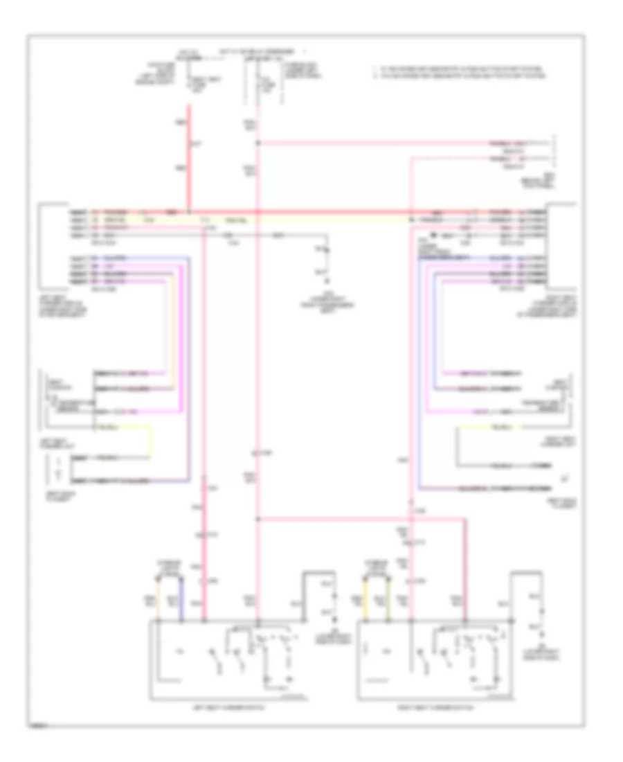
Heated Seats Wiring Diagram for Mazda 6 i Grand Touring 2011
List of elements for Heated Seats Wiring Diagram for Mazda 6 i Grand Touring 2011:
- 0913-103a
- 0913-103b
- 0913-104a
- 0913-104b
- 0940-01c
- 0940-01f
- 3ac
- A/c fuse 10a
- Bcm (behind left kick panel)
- C-07
- C-10 ad
- C-10 ag
- C-24
- C-24 i
- C-25
- C-25 i
- C-55 e
- C-55 f
- C-55 g
- Fuse block (under left side of dash)
- G16 (under right front passenger's seat)
- G9 (lower right side of dash)
- Hot at all times
- Hot in on
- Hot w/ ig2 relay energized
- Interior lights system
- Left seat warmer module (under right side of driver's seat)
- Left seat warmer switch
- Left seat warmer unit
- Main fuse block (left side of engine compt)
- Nca
- Pnk
- Red
- Right seat warmer module (under right side of passenger's seat)
- Right seat warmer switch
- Right seat warmer unit
- Seat back filament
- Seat cushion
- Seat heat fuse 20a
- Temperature sensor
- W/ advanced keyless entry & push button start system
- W/o advanced keyless entry & push button start system
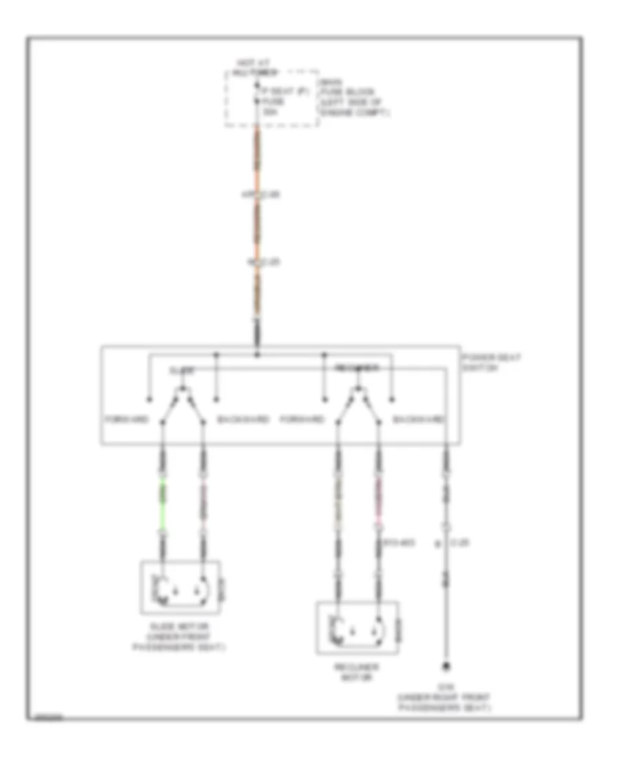
Passenger Power Seat Wiring Diagram for Mazda 6 i Grand Touring 2011
List of elements for Passenger Power Seat Wiring Diagram for Mazda 6 i Grand Touring 2011:
- 913-403 nca
- Ap c-06
- Back
- Backward
- C-25 b
- C-25 n
- Forward
- Front
- G16 (under right front passenger's seat)
- Hot at all times
- Main fuse block (left side of engine compt)
- Nca
- P seat (p) fuse 30a
- Power seat switch
- Recliner
- Recliner motor
- Slide
- Slide motor (under front passenger's seat)
POWER TOP/SUNROOF
Power Top/Sunroof Wiring Diagram for Mazda 6 i Grand Touring 2011
List of elements for Power Top/Sunroof Wiring Diagram for Mazda 6 i Grand Touring 2011:
- (left end of dash) g8
- 0922-101b
- 0940-01c
- 0940-01f
- 3ac
- A/c fuse 10a
- Bcm (behind left kick panel)
- C-06
- C-10
- C-22
- Close
- Computer data lines system
- Down
- Fuse block (under left side of dash)
- G14 (base of left "a" pillar)
- Hot at all times
- Hot in on or start
- Ic hall
- Input sensor
- Instrument cluster
- Instrument cluster system
- Main fuse block (left side of engine compt)
- Memory systems
- Micro computer
- Microcomputer
- Open
- Rom eep
- Slide
- Sunroof fuse 15a
- Sunroof motor (front of roof)
- Sunroof relay 1
- Sunroof relay 2
- Sunroof switch
- Tilt
POWER WINDOWS
Power Windows Wiring Diagram, with Driver & Passenger Side Window Auto Open/Close (1 of 2) for Mazda 6 i Grand Touring 2011
List of elements for Power Windows Wiring Diagram, with Driver & Passenger Side Window Auto Open/Close (1 of 2) for Mazda 6 i Grand Touring 2011:
- 0912-801a
- 0912-801b
- 0940-01f
- Auto
- Bcm (behind left kick panel)
- C-06
- C-29
- C-29 b
- C-31
- C-32
- Close
- Close relay
- Conjunction circuit
- Driver's side power window motor (in driver's door)
- G14 (base of left "a" pillar)
- Hall effect switch 1
- Hall effect switch 2
- Hot at all times
- Left rear power window motor (in left rear door)
- Left rear power window subswitch
- Main fuse block (left side of engine compt)
- Memory systems
- Mirrors system
- Open
- Open relay
- P wind (d) fuse 40a
- P wind (p) fuse 25a
- P/w cm
- Power window main switch/ power outer mirror switch/ retractable outer mirror switch
- Power-cut switch
- Right rear power window motor (in right rear door)
- Right rear power window subswitch
Power Windows Wiring Diagram, with Driver & Passenger Side Window Auto Open/Close (2 of 2) for Mazda 6 i Grand Touring 2011
List of elements for Power Windows Wiring Diagram, with Driver & Passenger Side Window Auto Open/Close (2 of 2) for Mazda 6 i Grand Touring 2011:
- 0914-401d
- 0921-201a
- 0921-201b
- 12v
- Auto
- C-05 an
- C-06 an
- C-10
- C-29 an
- C-30 b
- Close
- Close relay
- Fuse block (under left side of dash)
- G12 (right kick panel)
- G8 (left end of dash)
- Hall effect switch 1
- Hall effect switch 2
- Hot at all times
- Hot in run or start
- Ig key 1 fuse 40a
- Keyless control module (behind left side of dash)
- Main fuse block (left side of engine compt)
- Open
- Open relay
- P wind fuse 30a
- P/w cm
- Passenger's side power window motor (in right front door)
- Power window relay
- Relay block (lower left side of dash)
- Right front power window subswitch
- W/ advanced keyless entry & push button start system
- W/o advanced keyless entry & push button start system
Power Windows Wiring Diagram, with Driver Side Window Auto Open/Close (1 of 2) for Mazda 6 i Grand Touring 2011
List of elements for Power Windows Wiring Diagram, with Driver Side Window Auto Open/Close (1 of 2) for Mazda 6 i Grand Touring 2011:
- 0912-901a
- 0912-901b
- 0940-01f
- Ao c-06
- Auto
- Bcm (behind left kick panel)
- C-29 am
- C-29 b
- C-31
- Close
- Close relay
- Driver's side power window motor (in driver's door)
- G14 (base of left "a" pillar)
- Hall effect switch 1
- Hall effect switch 2
- Hot at all times
- Left rear power window motor (in left rear door)
- Left rear power window sub switch
- Main fuse block (left side of engine compt)
- Manual close
- Open
- Open manual
- Open relay
- P wind (d) fuse 40a
- P/w cm
- Power window main switch/ power outer mirror switch
- Power-cut switch
Power Windows Wiring Diagram, with Driver Side Window Auto Open/Close (2 of 2) for Mazda 6 i Grand Touring 2011
List of elements for Power Windows Wiring Diagram, with Driver Side Window Auto Open/Close (2 of 2) for Mazda 6 i Grand Touring 2011:
- 0914-401b
- 0914-401d
- 0921-201a
- 0921-201b
- Ap c-30
- C-05
- C-10 am
- C-10 s
- C-32
- Close
- Computer data lines system
- Fuse block (under left side of dash)
- G8 (left end of dash)
- Hot at all times
- Hot in on or start
- Ig key 1 fuse 40a
- Keyless control module (behind left side of dash)
- Main fuse block (left side of engine compt)
- Open
- P wind fuse 30a
- Passenger's side power window motor (in right front door)
- Power window relay
- Relay block (lower left side of dash)
- Right front power window sub switch
- Right rear power window close sub switch
- Right rear power window motor (in right rear door)
- W/ advanced keyless entry & push button start system
- W/o advanced keyless entry & push button start system
RADIO
Radio Wiring Diagram, with Bose (1 of 3) for Mazda 6 i Grand Touring 2011
List of elements for Radio Wiring Diagram, with Bose (1 of 3) for Mazda 6 i Grand Touring 2011:
- (lower center of dash) audio unit/car- navigation unit
- 0920-301a
- 0920-301b
- 0920-302a
- 0920-317
- 0920-318
- 0922-201
- 0922-202
- Aa c-13
- Audio amplifier (above right kick panel)
- Auxiliary jack (if equipped)
- C-13 an
- C-23
- Clock spring (in steering column)
- Computer data lines system
- G13 (front of right rear wheel well)
- G7 (lower left side of dash)
- Headlights system
- Instrument cluster system
- Interior lights system
- M c-13
- Microphone (center of dash)
- Mode
- Nca
- Red
- Seek+
- Seek-
- Steering switch
- Talk (w/ hands- free telephone (hf/tel) system)
- Vol+
- Vol-
- W/ audio display
- W/ navigation system
- W/o audio display
- W/o navigation system
Radio Wiring Diagram, with Bose (2 of 3) for Mazda 6 i Grand Touring 2011
List of elements for Radio Wiring Diagram, with Bose (2 of 3) for Mazda 6 i Grand Touring 2011:
- 0920-301d
- 0920-301e
- 0920-319
- 0920-320
- Antenna
- Antenna amplifier
- Audio unit/car-navigation unit (lower center of dash)
- C-10
- C-35
- C-61
- C-62
- C-63
- N c-10
- Nca
- Rear mount camera (if equipped)
- Red
- W/ navigation
- W/o navigation
- W/o rear mount camera/ w/ u-turn circuits
Radio Wiring Diagram, with Bose (3 of 3) for Mazda 6 i Grand Touring 2011
List of elements for Radio Wiring Diagram, with Bose (3 of 3) for Mazda 6 i Grand Touring 2011:
- (center of dash) microphone
- (front of right rear wheel well)
- 0920-302b
- 0920-302c
- 0920-315b
- Audio amplifier (above right kick panel)
- Audio fuse 30a
- C-07
- C-13
- C-22
- C-29
- C-30
- C-31
- C-32
- C-40
- Car-navigation unit (microphone) (lower center of dash)
- Center speaker
- Computer data lines system
- Fuse block (under left side of dash)
- G13
- G7 (lower left side of dash)
- Hot at all times
- Hot in run or acc
- Left front door speaker
- Left rear door speaker
- Left rear speaker
- Left tweeter
- Main fuse block (left side of engine compt)
- Mirror fuse 5a
- Nca
- Rear speaker
- Red
- Right front door speaker
- Right rear door speaker
- Right rear speaker
- Right tweeter
- Room fuse 15a
- Sirius satellite radio unit (if equipped) (right side of dash)
- W/ audio display
- W/ sirius satellite radio unit
Radio Wiring Diagram, without Bose for Mazda 6 i Grand Touring 2011
List of elements for Radio Wiring Diagram, without Bose for Mazda 6 i Grand Touring 2011:
- (if equipped) auxiliary jack
- 0920-201a
- 0920-201b
- 0920-201c
- 0920-210
- 0920-211
- 0922-201
- 0922-202
- Antenna
- Antenna amp
- Audio unit (lower center of dash)
- C-10
- C-13
- C-22
- C-23
- C-29
- C-30
- C-31
- C-32
- Car-navigation unit (microphone) (w/ car-navigation system) (lower center of dash)
- Clock spring (in steering column)
- Computer data lines system
- Fuse block (under left side of dash)
- G7 (lower left side of dash)
- Hot at all times
- Hot in run or acc
- Interior lights system
- Left front door speaker
- Left rear door speaker
- Left tweeter
- Microphone (left end of dash)
- Mirror fuse 5a
- Mode
- Nca
- Red
- Red c
- Right front door speaker
- Right rear door speaker
- Right tweeter
- Room fuse 15a
- Seek+
- Seek-
- Steering switch
- Vol+
- Vol-
- W/ audio display
SHIFT INTERLOCK
Shift Interlock Wiring Diagram for Mazda 6 i Grand Touring 2011
List of elements for Shift Interlock Wiring Diagram for Mazda 6 i Grand Touring 2011:
- (left rear of engine compt) pcm
- 0140-101a
- 0140-201a
- 0914-401c
- 1ab
- 2.5l
- 3.7l
- Aa c-06
- Brake switch (top of brake pedal)
- D c-10
- D c-13
- Fuse block (under left side of dash)
- G12 (right kick panel)
- Hot at all times
- Hot in on or acc hot w/ acc relay energized
- Int lock shift fuse 5a
- Key interlock solenoid (on steering column)
- Keyless control module (behind left side of dash)
- Main fuse block (left side of engine compt)
- P range off
- Selector lever component
- Shift- lock solenoid
- Stop fuse 10a
- W/ advanced keyless entry
- W/o advanced keyless entry
Steering Column Wiring Diagram for Mazda 6 i Grand Touring 2011
List of elements for Steering Column Wiring Diagram for Mazda 6 i Grand Touring 2011:
- 0914-401a
- 0914-401b
- 0914-401d
- C-06
- C-11
- Escl fuse 10a
- G8 (left end of dash)
- Hot at all times
- Keyless control module (behind left side of dash)
- Main fuse block (left side of engine compt)
- Red
- Steering lock unit (in steering column)
STARTING/CHARGING
Charging Wiring Diagram for Mazda 6 i Grand Touring 2011
List of elements for Charging Wiring Diagram for Mazda 6 i Grand Touring 2011:
- 1ah
- 1ai
- 1al
- 1am
- 1bf
- 2.5l
- 2aa
- 2af
- 3.7l
- Battery
- C-02
- C-04
- Charge ind
- Computer data lines system
- Eng +b fuse 10a
- Fuse block (under left side of dash)
- Generator
- Hot in on or start
- Instrument cluster
- Main fuse 125a
- Main fuse block (left side of engine compt)
- Meter fuse 15a
- Microcomputer
- Nca
- O140-101a
- O140-101b
- O140-201a
- Pcm (left rear of engine compt)
- Red
- Starting circuit
Starting Wiring Diagram for Mazda 6 i Grand Touring 2011
List of elements for Starting Wiring Diagram for Mazda 6 i Grand Touring 2011:
- 0140-101a
- 0140-201a
- 0517-201a
- 0914-401d
- 0940-01b
- 0940-01d
- 140-201a
- 1aq
- 1bb
- 1bd
- 2.5l
- 3.7l
- 4aa
- A/t
- Acc
- Battery
- Bcm (behind left kick panel)
- C-02
- C-05
- C-06
- C-13
- Fuse block (under left side of dash)
- Hold
- Hot in on or start
- Ig key2 fuse 40a
- Ignition switch
- Keyless control module (if equipped) (behind left side of dash)
- M/t
- Main fuse 125a
- Main fuse block (left side of engine compt)
- Meter ig fuse 15a
- Nca
- Off
- Pcm (left rear of engine compt)
- Pull-in
- Red
- St sig fuse 5a
- Start
- Starter
- Starter interlock switch (behind left side of dash)
- Starter relay
- Starter relay 2 (3.7l)
- Transaxle control module
- Transaxle range switch (left side of transaxle)
- W/ advanced keyless entry & push button start system
- W/o advanced keyless entry & push button start system
SUPPLEMENTAL RESTRAINTS
Supplemental Restraints Wiring Diagram (1 of 2) for Mazda 6 i Grand Touring 2011
List of elements for Supplemental Restraints Wiring Diagram (1 of 2) for Mazda 6 i Grand Touring 2011:
- & push button start system
- (front of left rear wheel well) driver side side air bag sensor 2
- (if equipped) passenger air bag deactivation (pad) indicator
- (left side of driver's seat back) driver side side air bag module
- (right side of front passenger's seat back) passenger side side air bag module
- 0810-01a
- 0810-01b
- 0810-01c
- 0810-04
- 0810-14
- 0810-15
- 0810-24
- C-08
- C-09
- C-13 b
- C-24
- C-25 b
- C-29
- C-30
- C-55 b
- Clock spring (in steering column)
- Computer data lines system
- Driver side air bag module 1 (in steering wheel)
- Driver side air bag module 2 (in steering wheel)
- Driver side buckle switch (in driver's seat belt buckle assembly)
- Driver side pressure sensor (if equipped)
- Fuse block (under left side of dash)
- G16 (under right front passenger's seat)
- Hot w/ ig 1 relay energized hot in run or start
- Inflator
- Meter ig fuse 15a
- Nca
- Passenger side air bag module 1
- Passenger side air bag module 2
- Passenger side buckle switch (if equipped) (in passenger's seat belt buckle assembly)
- Passenger side pressure sensor (if equipped)
- Power distribution system
- Sas control module (under front of center console)
- Sas fuse 5a
- Short bar
- W/ advanced keyless entry
- W/o advanced keyless entry & push button start system
Supplemental Restraints Wiring Diagram (2 of 2) for Mazda 6 i Grand Touring 2011
List of elements for Supplemental Restraints Wiring Diagram (2 of 2) for Mazda 6 i Grand Touring 2011:
- (front of right rear wheel well) passenger side side air bag sensor 2
- (near base of left "b" pillar) driver side side air bag sensor 1
- (near base of right "b" pillar) passenger side side air bag sensor 1
- (top of left "d" pillar) driver side curtain air bag module
- (top of right "c" pillar) passenger side curtain air bag module
- 0810-22
- 0810-23
- 0810-27a
- 0810-27b
- 0810-27c
- 0922-101b
- 0940-01c
- 0940-01f
- 3ab
- Air bag ind
- B c-25
- Bcm (behind left kick panel)
- C-07
- C-24
- C-25
- Circuit failure detection
- Computer data lines system
- Crash zone sensor (right front of engine compt)
- Driver side pretensioner seat belt (base of left "b" pillar)
- G16 (under right front passenger's seat)
- G8 (left end of dash)
- Inflator
- Instrument cluster
- Left seat weight sensor (under left side of front passenger's seat)
- Microcomputer
- Nca
- Passenger side pretensioner seat belt (base of right "b" pillar)
- Right seat weight sensor (under right side of front passenger's seat)
- Seat belt ind
- Seat track position sensor (w/ seat weight sensor) (under right front of driver's seat)
- Seat weight sensor control module (if equipped) (under front 0810-27c passenger's seat)
- Short bar
TRANSMISSION
2.5L
2.5L, Transmission Wiring Diagram (1 of 2) for Mazda 6 i Grand Touring 2011
List of elements for 2.5L, Transmission Wiring Diagram (1 of 2) for Mazda 6 i Grand Touring 2011:
- (behind left kick panel) bcm
- 0517-101a
- 0517-101b
- 0940-01b
- 0940-01d
- 0940-01f
- At main relay
- C-02
- C-06
- Computer data lines system
- Down switch
- Eng +b fuse 10a
- Fuse block (under left side of dash)
- G12 (right kick panel)
- G5 (base of left "a" pillar)
- Hot at all times
- Hot in on or start
- Ill
- Input/turbine speed sensor (on transaxle)
- Interior lights system
- Intermediate sensor (on transaxle)
- M range switch
- Main fuse block (left side of engine compt)
- Meter fuse 15a
- Oil pressure switch (engine control: left rear of engine) (cluster indicator: left side of engine)
- Red
- Selector lever component
- Starting/charging system
- Tcm (lower left side of dash)
- Tcm fuse 20a
- Up switch
- Vehicle speed sensor (on transaxle)
2.5L, Transmission Wiring Diagram (2 of 2) for Mazda 6 i Grand Touring 2011
List of elements for 2.5L, Transmission Wiring Diagram (2 of 2) for Mazda 6 i Grand Touring 2011:
- 0517-105
- 0517-107
- A solenoid control pressure
- C-02
- G19 (on transaxle)
- G20 (rear of engine)
- R position
- Red
- Shift solenoid b
- Shift solenoid d
- Solenoid a shift
- Solenoid b control pressure
- Solenoid c shift
- Solenoid e shift
- Solenoid f shift
- Starting/ charging system
- Transaxle case
- Transaxle fluid temperature sensor
- Transaxle range switch (left side of transaxle)
3.7L
3.7L, Transmission Wiring Diagram for Mazda 6 i Grand Touring 2011
List of elements for 3.7L, Transmission Wiring Diagram for Mazda 6 i Grand Touring 2011:
- 0517-201a
- 0517-201b
- 0940-01b
- 0940-01d
- 0940-01f
- A10
- A11
- A12
- A13
- A14
- A15
- A16
- B10
- B11
- B12
- B13
- B14
- B15
- B16
- B17
- B18
- B19
- B20
- B21
- B22
- Bcm (behind left kick panel)
- C-02
- C-06
- Computer data lines system
- Control valve body (on transaxle)
- Down sw
- Exterior lights system
- Fuse block (under left side of dash)
- G12 (right kick panel)
- G3 (left side of engine compt)
- Hot at all times
- Hot in on or start
- Ill
- Input/turbine speed sensor (on transaxle)
- Interior lights system
- Line pressure control solenoid
- M range sw
- Main fuse block (left side of engine compt)
- Meter fuse 15a
- Nca
- Red
- Selector lever component
- Shift solenoid a
- Shift solenoid d
- Shift solenoid e
- Solenoid b shift
- Solenoid c shift
- Solenoid f shift
- Solenoid tcc control
- Starting/charging system
- Tcm (rear of engine)
- Tcm fuse 20a
- Transaxle fluid temperature sensor
- Up sw
- Vehicle speed sensor (on transaxle)
- W c-02
TRUNK, TAILGATE, FUEL DOOR
Trunk Release Wiring Diagram for Mazda 6 i Grand Touring 2011
List of elements for Trunk Release Wiring Diagram for Mazda 6 i Grand Touring 2011:
- (left front of engine compt) g2
- 0914-401c
- 0940-01b
- 0940-01c
- 0940-01f
- 0940-01g
- Bcm (behind left kick panel)
- C-35
- C-62
- C-62 g
- C-63
- D c-62
- G18 (front of left rear wheel well)
- G8 (left end of dash)
- Hot at all times
- Interior lights system
- Keyless control module (behind left side of dash)
- Main fuse block (left side of engine compt)
- Nca
- Red
- Tail fuse 15a
- Trunk lid opener & trunk compartment light switch (trunk lid opener: center rear of trunk lid)
- Trunk lid opener switch (vehicle exterior)
- Trunk lid opener switch (vehicle interior)
- W/ advance keyless entry & push button start system
- W/ rear mount camera
WARNING SYSTEMS
Chime Wiring Diagram for Mazda 6 i Grand Touring 2011
List of elements for Chime Wiring Diagram for Mazda 6 i Grand Touring 2011:
- 0810-01b
- 0810-01c
- 0922-101b
- 0940-01a
- 0940-01c
- 0940-01f
- 0940-01h
- Bcm (behind left kick panel)
- Brake fluid level sensor (in brake fluid reservoir)
- Brake ind
- Buzzer
- C-24
- C-25
- C-29
- C-30
- C-31
- C-32
- Computer data lines system
- Door ind
- Driver-side buckle switch (in driver's seat belt buckle assembly)
- Entry & push button start system
- Fuse block (under left side of dash)
- G12 (right kick panel)
- G14 (base of left "a" pillar)
- G16 (under right front passenger's seat)
- G3 (left side of engine compt)
- G8 (left end of dash)
- Hot at all times
- Hot in ig1 relay energized
- Hot in run or start
- Instrument cluster
- Key reminder switch (on steering column)
- Keyless switch smart (on steering column)
- Left front door latch & lock actuator (in driver's door)
- Left rear door latch & lock actuator (rear of left rear door)
- Memory systems
- Meter ig fuse 15a
- Microcomputer
- Parking brake switch (at base of parking brake assembly)
- Passenger-side buckle switch (if equipped) (in passenger's seat belt buckle assembly)
- Right front door latch & lock actuator (in passenger's door)
- Right rear door latch & lock actuator (rear of right rear door)
- Room fuse 15a
- Sas control module (under front of center console)
- Seat belt ind
- W/ advanced keyless
- W/o advanced keyless
Tire Pressure Monitoring Wiring Diagram for Mazda 6 i Grand Touring 2011
List of elements for Tire Pressure Monitoring Wiring Diagram for Mazda 6 i Grand Touring 2011:
- (behind right side of dash) (w/o advanced keyless entry & push button start system) keyless receiver/ tpms control module
- 0914-401b
- 0922-101b
- 0940-01f
- Bcm (behind left kick panel)
- Buzzer
- C-10
- C-13
- Computer data lines system
- Entry & push button start system
- Fuse block (under left side of dash)
- G8 (left end of dash)
- Hot at all times
- Hot in on or start
- Hot w/ ig1 relay energized
- Instrument cluster
- Keyless control module (behind left side of dash)
- Keyless receiver/ tpms control module (behind right side of dash)
- Meter ig fuse 15a
- Microcomputer
- Room fuse 15a
- Tpms ind
- W/ advanced keyless
- W/o advanced keyless entry & push button start system
WIPER/WASHER
Wiper/Washer Wiring Diagram, with Auto Wiper System for Mazda 6 i Grand Touring 2011
List of elements for Wiper/Washer Wiring Diagram, with Auto Wiper System for Mazda 6 i Grand Touring 2011:
- (base of left "a" pillar) g14
- 0914-401d
- 0918-101a
- 0918-101b
- 0921-201a
- 0921-201b
- 0922-101a
- 0922-101b
- 0940-01d
- 0940-01g
- Auto
- Auto int
- Auto light sensor/ rain sensor (on back of rear view mirror)
- Auto light/wiper control module (behind left side of dash)
- Autostop switch
- Bcm (behind left kick panel)
- C-05
- C-10
- C-11
- C-21
- Circuit breaker
- Computer data lines system
- Fuse block (under left side of dash)
- G1 (right front of engine compt)
- G14 (base of left "a" pillar)
- G8 (left end of dash)
- Gnd
- H/l
- High low
- Hot at all times
- Hot in on
- Hot w/ ig1 relay energized hot in on or start
- Ig key2 fuse 40a
- Instrument cluster
- Instrument cluster system
- Intermittent volume
- Keyless control module (behind left side of dash)
- Light switch
- Main fuse block (left side of engine compt)
- Meter ig fuse 15a
- Microcomputer
- Mist
- Off
- Red
- Relay block (lower left side of dash)
- Tns
- W/ advanced keyless entry & push button start system
- W/o advanced keyless entry & push button start system
- Washer fluid-level sensor (in washer fluid reservoir)
- Washer ind
- Windshield washer motor (on washer fluid reservoir)
- Windshield washer switch
- Windshield wiper & washer switch
- Windshield wiper motor (left rear of engine compt)
- Windshield wiper relay
- Wiper fuse 25a
Wiper/Washer Wiring Diagram, without Auto Wiper System for Mazda 6 i Grand Touring 2011
List of elements for Wiper/Washer Wiring Diagram, without Auto Wiper System for Mazda 6 i Grand Touring 2011:
- (right front of
- 0914-401d
- 0921-201a
- 0921-201b
- 0922-101a
- 0922-101b
- Autostop switch
- C-05
- C-05 a
- C-10
- Circuit breaker
- Computer data lines system
- Engine compt)
- Fuse block (under left side of dash)
- G c-10
- G1 (right front of engine compt)
- G14 (base of left "a" pillar)
- G8 (left end of dash)
- Gnd
- Hot at all times
- Hot in on
- Hot w/ ig1 relay energized hot in on or start
- Ig key2 fuse 40a
- Instrument cluster
- Int
- Intermittent relay
- Intermittent volume
- Keyless control module (behind left side of dash)
- Low
- Main fuse block (left side of engine compt)
- Meter ig fuse 15a
- Microcomputer
- Mist
- Off
- Red
- Relay block (lower left side of dash)
- W/ advanced keyless entry & push button start system
- W/o advanced keyless entry & push button start system
- Washer fluid-level sensor (in washer fluid reservoir)
- Washer ind
- Windshield washer motor (on washer fluid reservoir)
- Windshield washer switch
- Windshield wiper & washer switch
- Windshield wiper motor (left rear of engine compt)
- Windshield wiper relay
- Wiper fuse 25a