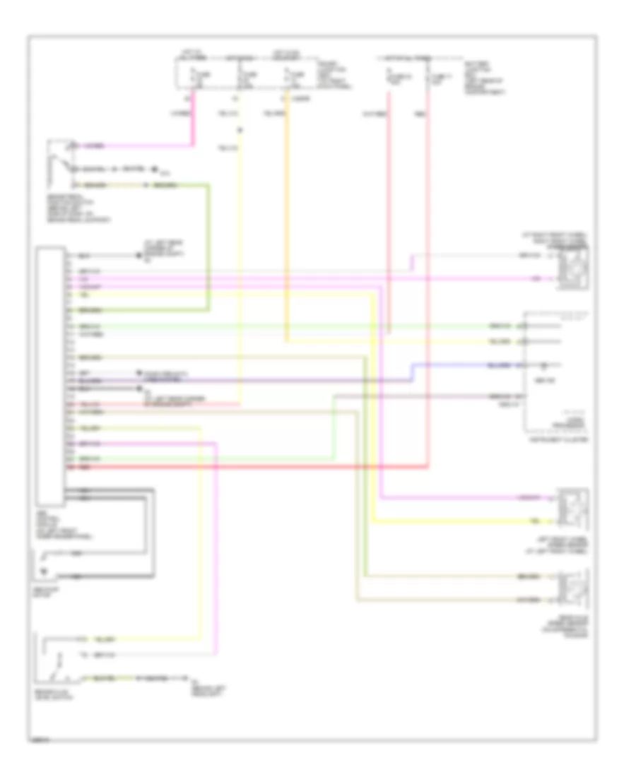
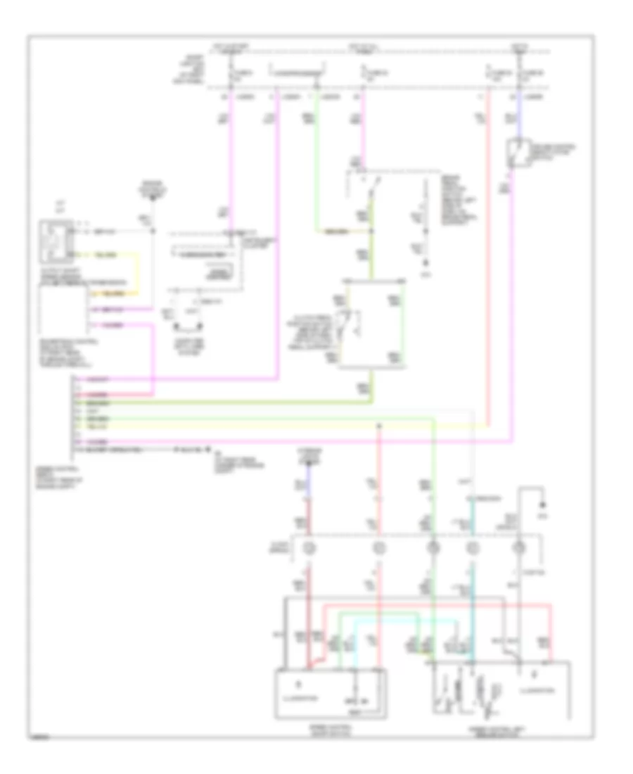
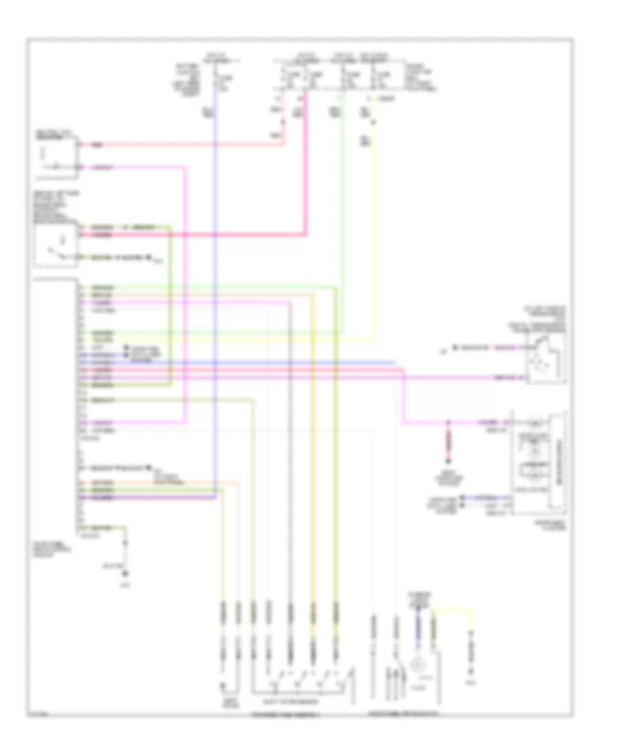
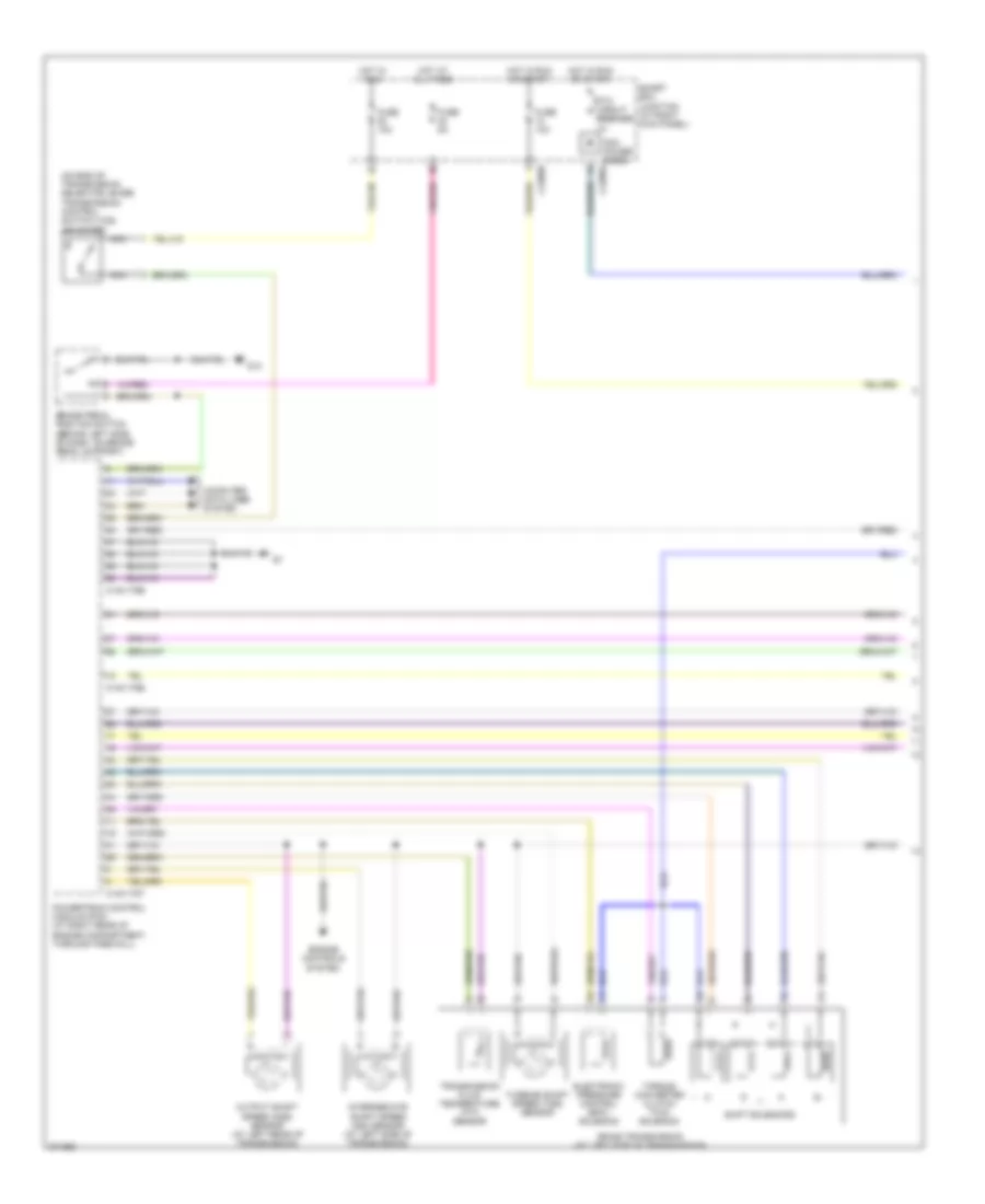
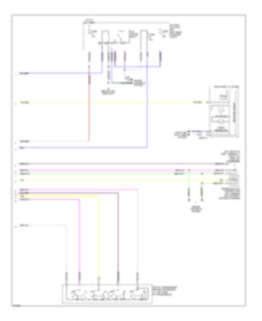
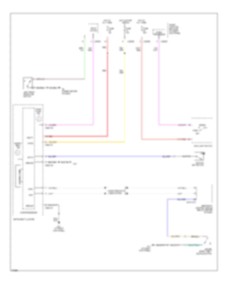
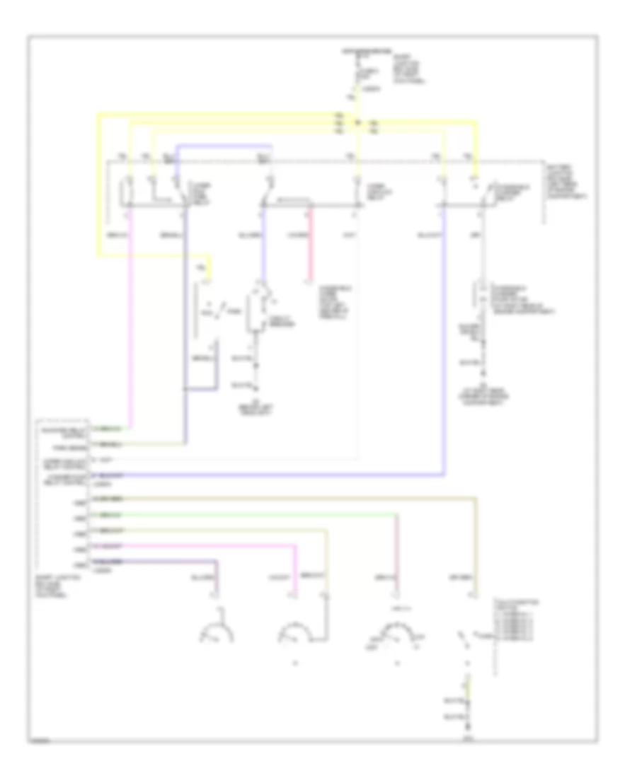
AIR CONDITIONING
Manual A/C Wiring Diagram for Mazda B2007 4000

List of elements for Manual A/C Wiring Diagram for Mazda B2007 4000:
- (2.3l)
- (behind left headlight) g4
- (behind right side of dash) blend door actuator
- (except 2.3l)
- (left rear of engine compt) battery junction box
- (right rear of engine compt, on firewall) heater blower motor
- 0140-175b
- 0140-175e
- 0740-101
- 0740-102
- 0740-103
- 0740-104
- 2.3l
- A/c
- A/c clutch field coil
- A/c clutch relay
- A/c compressor cycling switch (in right side of engine compt, on a/c accumulator)
- A/c high pressure switch (at left front of engine compt)
- Battery junction box (left rear of engine compt)
- Blower motor relay
- Blower motor switch
- Circuit breaker ptc
- Cylinder head temperature sensor (2.3l) (on right side of cylinder head)
- Defrost
- Engine controls system
- Engine coolant temperature (ect) sensor (3.0l, 4.0l) (3.0l: on top left front of engine) (4.0l: on top front center of engine)
- Engine cooling fan motor (2.3l) (at right front of engine compt)
- Engine cooling fan relay (2.3l)
- Except 2.3l
- Floor
- Flr/def
- Front function selector switch assembly
- Front heater blower motor resistor (right rear of engine compt, near blower motor)
- Fuse 10a
- Fuse 20a
- Fuse 30a
- G13
- G4 (behind left headlight)
- G5 (at right rear corner of engine compt)
- Hot at all times
- Hot in on or start
- Hot in run
- Illumination
- Interior lights system
- J-2280a
- J-2280b
- Max a/c
- Med hi
- Med lo
- Mode switch
- Off
- Panel
- Pcm power diode
- Pcm power relay
- Powertrain control module (pcm) (at right rear of engine compt, through firewall)
- Red
- Smart junction box (at right kick panel)
- Thermal limiter
ANTI-LOCK BRAKES
Anti-lock Brakes Wiring Diagram for Mazda B2007 4000
List of elements for Anti-lock Brakes Wiring Diagram for Mazda B2007 4000:
- (at left rear corner of engine compt) g3
- (at right front wheel) right front wheel speed sensor
- 0922-101
- Abs control module (on left front inner fender panel)
- Abs ind
- Abs pump motor
- Battery junction box (left rear of engine compartment)
- Brake fluid level switch
- Brake pedal position switch (behind left side of dash, on brake pedal support)
- Computer data lines system
- Fuse 10a
- Fuse 17 40a
- Fuse 33 30a
- Fuse 5a
- G13
- G3 (at left rear corner of engine compt)
- G4 (behind left headlight)
- Hot at all times
- Hot in on or start
- Hot in run
- Instrument cluster
- J-2280b
- Left front wheel speed sensor (at left front wheel)
- Micro- processor
- Nca
- Rear axle speed sensor (on differential housing)
- Red
- Smart junction box (at right kick panel)
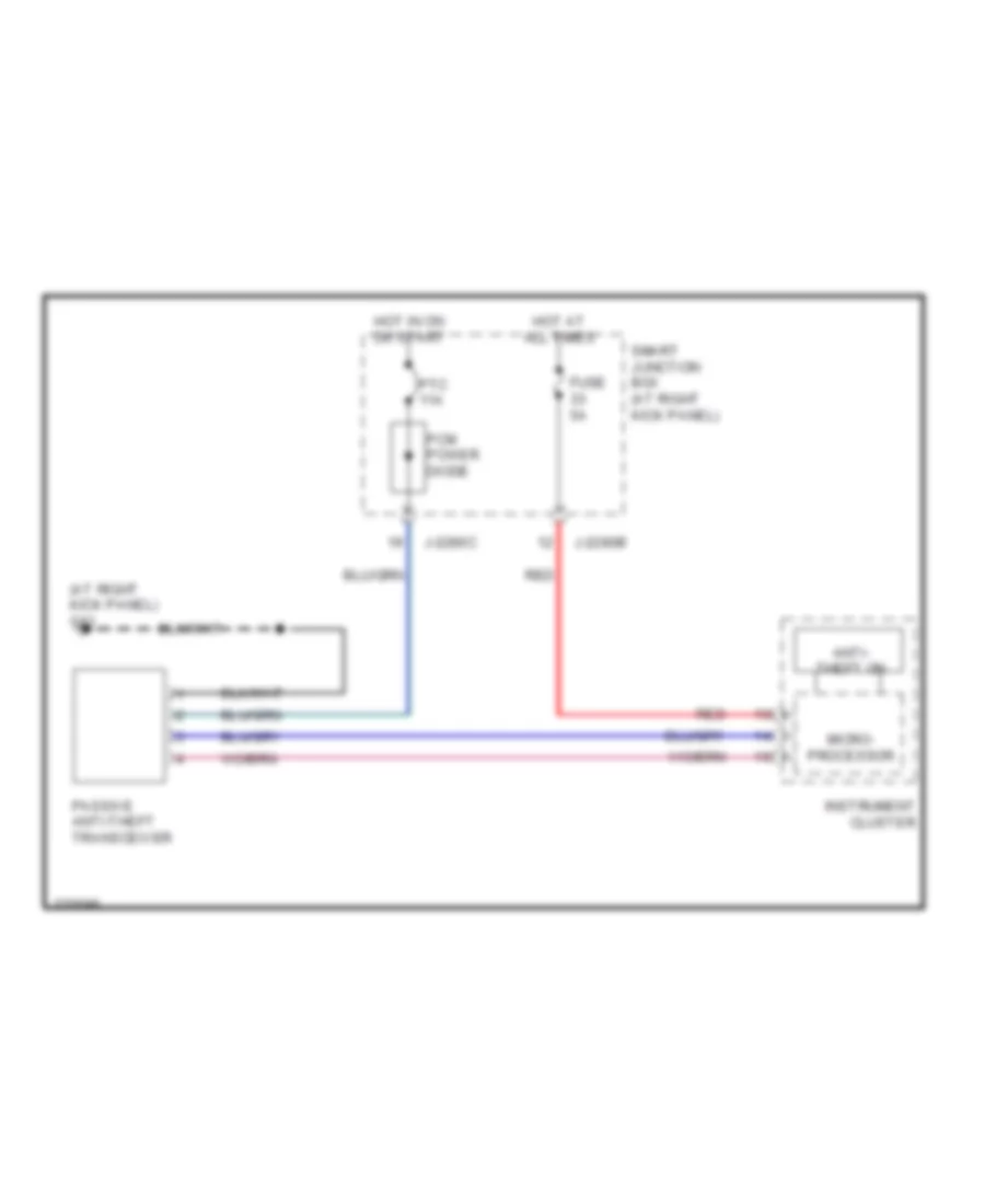
ANTI-THEFT
Forced Entry Wiring Diagram for Mazda B2007 4000
List of elements for Forced Entry Wiring Diagram for Mazda B2007 4000:
- (not used)
- Door lock/
- Driver door lock relay
- Driver side door lock switch
- Exterior lights system
- Fuse 15a
- Fuse 20a
- Fuse 5a
- G11 (at right kick panel)
- G13
- G8 (under center of dash)
- G9 (at left kick panel)
- Horn relay
- Horns system
- Hot at all times
- Instrument cluster system
- Instrument panel dimming module (left side of dash)
- Interior lights system
- J-2280a
- J-2280b
- J-2280c
- J-2280d
- Left front door ajar switch
- Left front door lock actuator (at rear of left front door)
- Left rear door ajar switch (4 door)
- Lock
- Microprocessor
- Park lamp relay
- Passenger side door lock switch
- Right front door ajar switch
- Right front door lock actuator (at rear of right front door)
- Right rear door ajar switch (4 door)
- Smart junction box (at right kick panel)
- Solid state
- Unlock
- Unlock relay
Immobilizer Wiring Diagram for Mazda B2007 4000
List of elements for Immobilizer Wiring Diagram for Mazda B2007 4000:
- (at right kick panel) g11
- Anti- theft on
- Fuse 5a
- Hot at all times
- Hot in on or start
- Instrument cluster
- J-2280b
- J-2280c
- Micro- processor
- Passive anti-theft transceiver
- Pcm power diode
- Ptc 11a
- Red
- Smart junction box (at right kick panel)
BODY CONTROL MODULES
Body Control Modules Wiring Diagram for Mazda B2007 4000
List of elements for Body Control Modules Wiring Diagram for Mazda B2007 4000:
- (at right kick panel) g11
- (not used)
- Acc
- Accessory relay
- Cruise control system
- Door lock/ unlock relay
- Door locks system
- Driver door lock relay
- Exterior lights system
- Fuse 1 5a
- Fuse 10a
- Fuse 14 15a
- Fuse 3 10a
- Fuse 30a
- Fuse 4 10a
- G10 (under driver's seat)
- Headlights system
- Horn relay
- Horns system
- Hot at all times
- Hot in run or acc
- Ignition switch
- Instrument cluster & transmissions systems
- Interior lamp relay
- Interior lights system
- J-2280a
- J-2280b
- J-2280c
- J-2280d
- Lock
- Microprocessor
- Off
- One-touch window relay
- Park lamp relay
- Power windows system
- Run
- Smart junction box (at right kick panel)
- Solid state
- Start
- Wiper/washer system
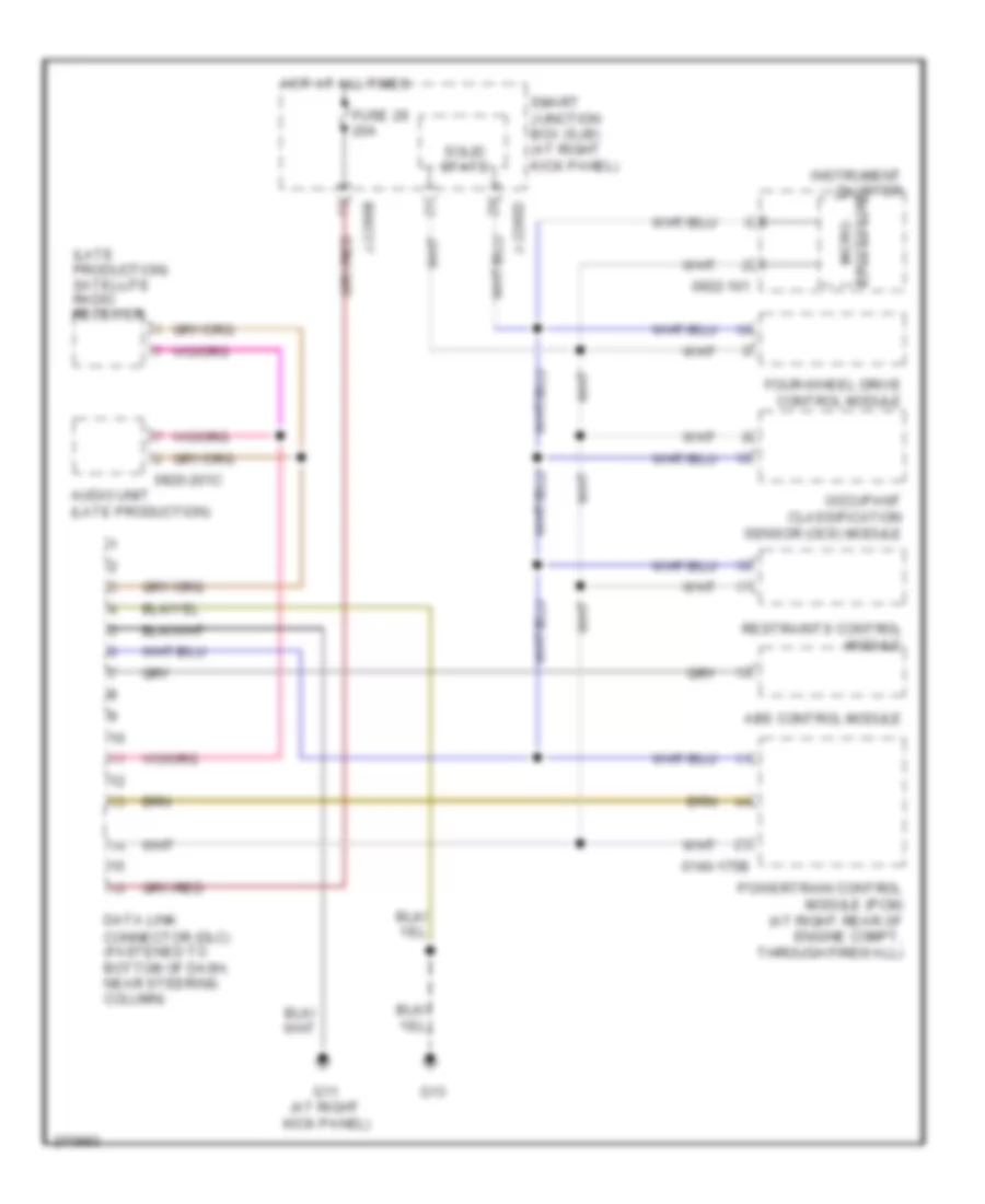
COMPUTER DATA LINES
Computer Data Lines Wiring Diagram for Mazda B2007 4000
List of elements for Computer Data Lines Wiring Diagram for Mazda B2007 4000:
- (late production) satellite radio receiver
- 0140-175b
- 0920-201c
- 0922-101
- Abs control module
- Audio unit (late production)
- Data link connector (dlc) (fastened to bottom of dash, near steering column)
- Four-wheel drive control module
- Fuse 29 20a
- G11 (at right kick panel)
- G13
- Hot at all times
- Instrument cluster
- J-2280b
- J-2280d
- Occupant classification sensor (ocs) module
- Powertrain control module (pcm) (at right rear of engine compt, through firewall)
- Processor micro-
- Restraints control module
- Smart junction box (sjb) (at right kick panel)
- Solid state
CRUISE CONTROL
Cruise Control Wiring Diagram for Mazda B2007 4000
List of elements for Cruise Control Wiring Diagram for Mazda B2007 4000:
- 0120-102
- 0922-101
- 0922-202a
- 10a
- A/t
- Brake pedal position switch (behind left side of dash, on brake pedal support)
- Clock spring
- Clutch pedal position switch (behind left side of dash, top of clutch pedal support)
- Coast(-)
- Computer data lines system
- Cruise control deactivator switch
- Engine controls system
- Fuse 20
- Fuse 26
- Fuse 32
- Fuse 9
- G12
- G13
- G5 (at right rear corner of engine compt)
- Hot at all times
- Hot in run
- Hot in start or run
- Illumination
- Instrument cluster
- Interior lights system
- J-2280a
- J-2280b
- J-2280c
- J-2280d
- M/t
- Microcomputer
- Microprocessor
- Off
- Output shaft speed sensor (at left rear of transmission)
- Powertrain control module (pcm) (at right rear of engine compt, through firewall)
- Rest
- Resume
- Set(+)
- Smart junction box (at right kick panel)
- Speed control
- Speed control on/off switch
- Speed control servo (in right rear of engine compt)
- Speed control set/ resume switch
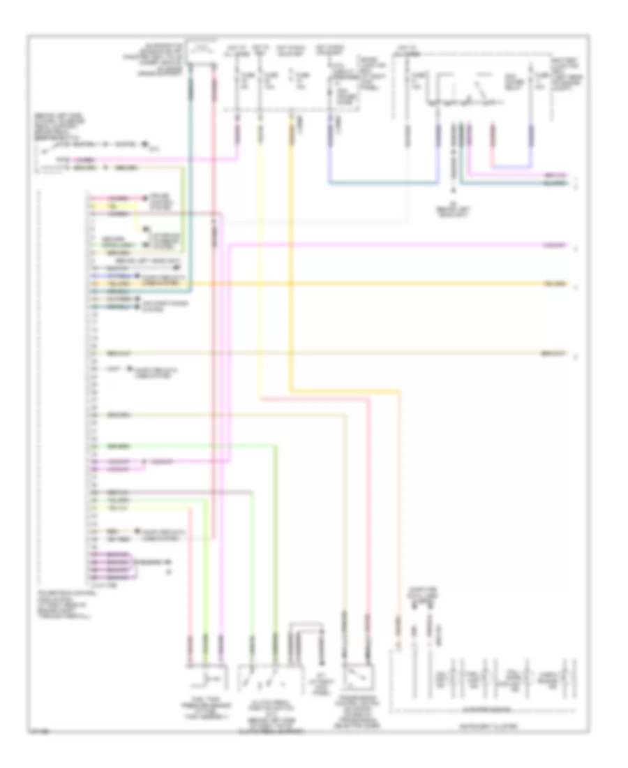
ENGINE PERFORMANCE
4.0L
4.0L, Engine Performance Wiring Diagram (1 of 4) for Mazda B2007 4000
List of elements for 4.0L, Engine Performance Wiring Diagram (1 of 4) for Mazda B2007 4000:
- (behind left headlight) g6
- (behind left side of dash, on brake pedal support) brake pedal position switch
- 0140-175b
- 0922-101
- Air conditioning system
- Battery junction box (left rear of engine compt)
- Check engine ind
- Clutch pedal position switch (m/t) (behind left side of dash, top of clutch pedal support)
- Computer data lines system
- Cruise control system
- Evaporative emission (evap) canister vent valve (under vehicle, on frame cross support)
- Fail- safe cooling ind
- Fuel cap ind
- Fuel tank pressure sensor (at fuel tank assembly)
- Fuse 10a
- Fuse 30a
- Fuse 5a
- G11 (at right kick panel)
- G13
- G4 (behind left headlight)
- Hot at all times
- Hot in run
- Hot in run or start
- Instrument cluster
- J-2280a
- J-2280b
- Microprocessor
- Nca
- O/d off ind
- Pcm power diode
- Pcm power relay
- Powertrain control module (pcm) (at right rear of engine compt, through firewall)
- Ptc circuit breaker 1a
- Smart junction box (at right kick panel)
- Starting/ charging system
- Transmission control switch (od on/off) (on end of transmission selector lever)
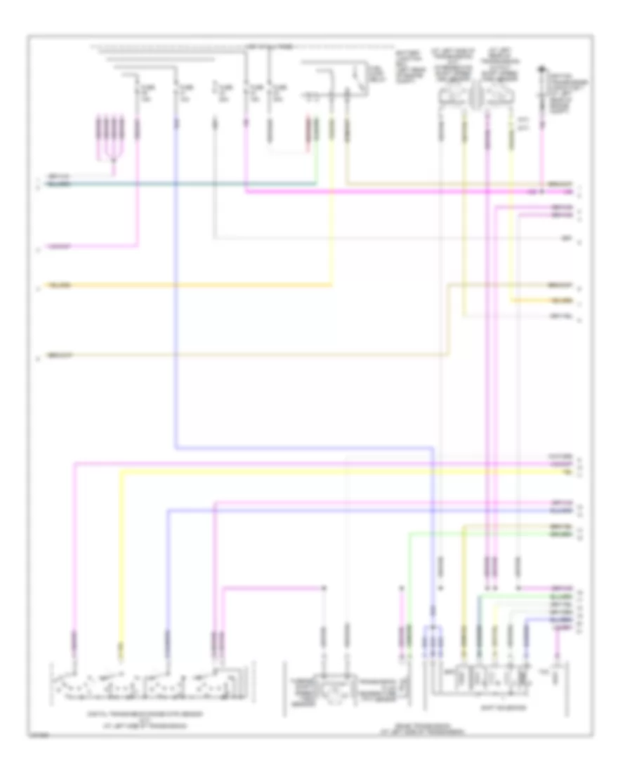
4.0L, Engine Performance Wiring Diagram (2 of 4) for Mazda B2007 4000
List of elements for 4.0L, Engine Performance Wiring Diagram (2 of 4) for Mazda B2007 4000:
- (a/t)
- (at left rear of transmission) output shaft speed (oss) sensor
- (at left side of transmission) (a/t) intermediate shaft speed (iss) sensor
- (m/t)
- 5r44e transmission (at left side of transmission)
- Battery junction box (left rear of engine compt)
- Digital transmission range (dtr) sensor (a/t) (at left side of transmission)
- Epc
- Fuel pump relay
- Fuse 10a
- Fuse 15a
- Fuse 20a
- Fuse 30a
- Hot at all times
- Ignition transformer capacitor 1 (at left rear of engine compt)
- Nca
- Shift solenoids
- Tcc
- Transmission fluid temperature (tft) sensor
- Turbine shaft speed (tss) sensor
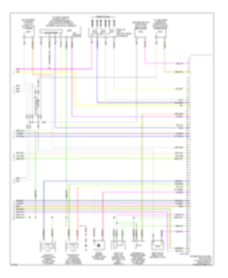
4.0L, Engine Performance Wiring Diagram (3 of 4) for Mazda B2007 4000
List of elements for 4.0L, Engine Performance Wiring Diagram (3 of 4) for Mazda B2007 4000:
- (4, 5 & 6: at top of left cylinder bank) (1, 2 & 3: at top of right cylinder bank) fuel injectors
- (at right kick panel) inertia fuel shutoff (ifs) switch
- (at right rear of engine, in exhaust) heated oxygen sensor (ho2s) 22
- (at underside of vehicle, in exhaust, near transmission) heated oxygen sensor (ho2s) 12
- (behind left headlight) g4
- (in fuel tank) fuel tank unit
- (on top front center of engine) engine coolant temperature (ect) sensor
- 0140-175t
- Fuel gauge sensor
- Fuel pump
- G11
- Heated oxygen sensor (ho2s) 11 (at rear of of engine, in exhaust)
- Heated oxygen sensor (ho2s) 21 (at lower rear center of engine compt, in exhaust)
- Instrument cluster system
- Powertrain control module (pcm) (at right rear of engine compt, through firewall)
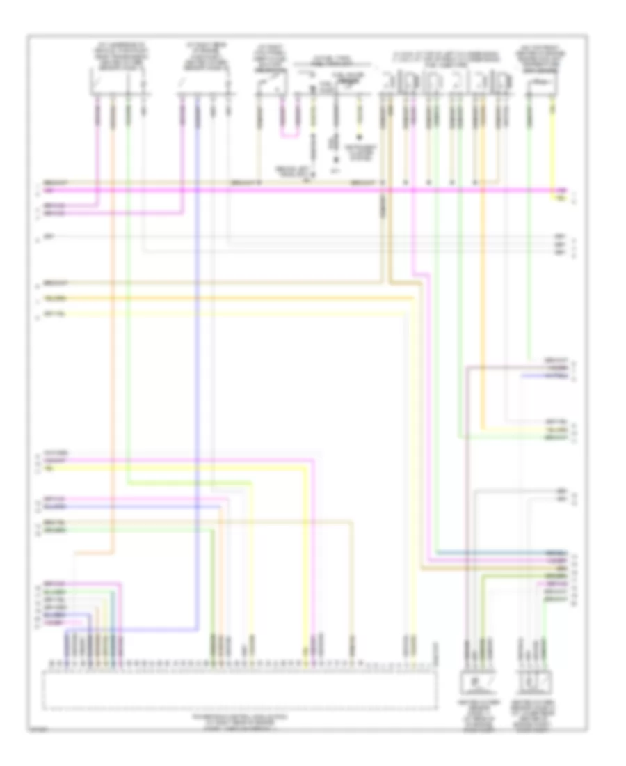
4.0L, Engine Performance Wiring Diagram (4 of 4) for Mazda B2007 4000
List of elements for 4.0L, Engine Performance Wiring Diagram (4 of 4) for Mazda B2007 4000:
- (at left rear corner of engine compt) evap canister purge valve
- (at right side of engine compt, in air cleaner assembly) mass air flow/intake air temperature (maf/iat) sensor
- (on top front of engine) idle air control (iac) valve
- 0140-175e
- Act sensor
- Air conditioning system
- Camshaft position (cmp) sensor (on left side of engine)
- Crankshaft position (ckp) sensor (on lower right front of engine)
- Differential pressure feed- back egr (dpfe) sensor (on left side of engine)
- Egr vacuum regulator solenoid valve
- Heated positive crankcase ventilation (pcv) valve
- Ignition coil (on left rear of engine)
- Knock sensor (on right side of engine)
- Nca
- Powertrain control module (pcm) (at right rear of engine compt, through firewall)
- Solid state
- Spark plugs
- Throttle position sensor (tps) (on throttle body assembly)
EXTERIOR LIGHTS
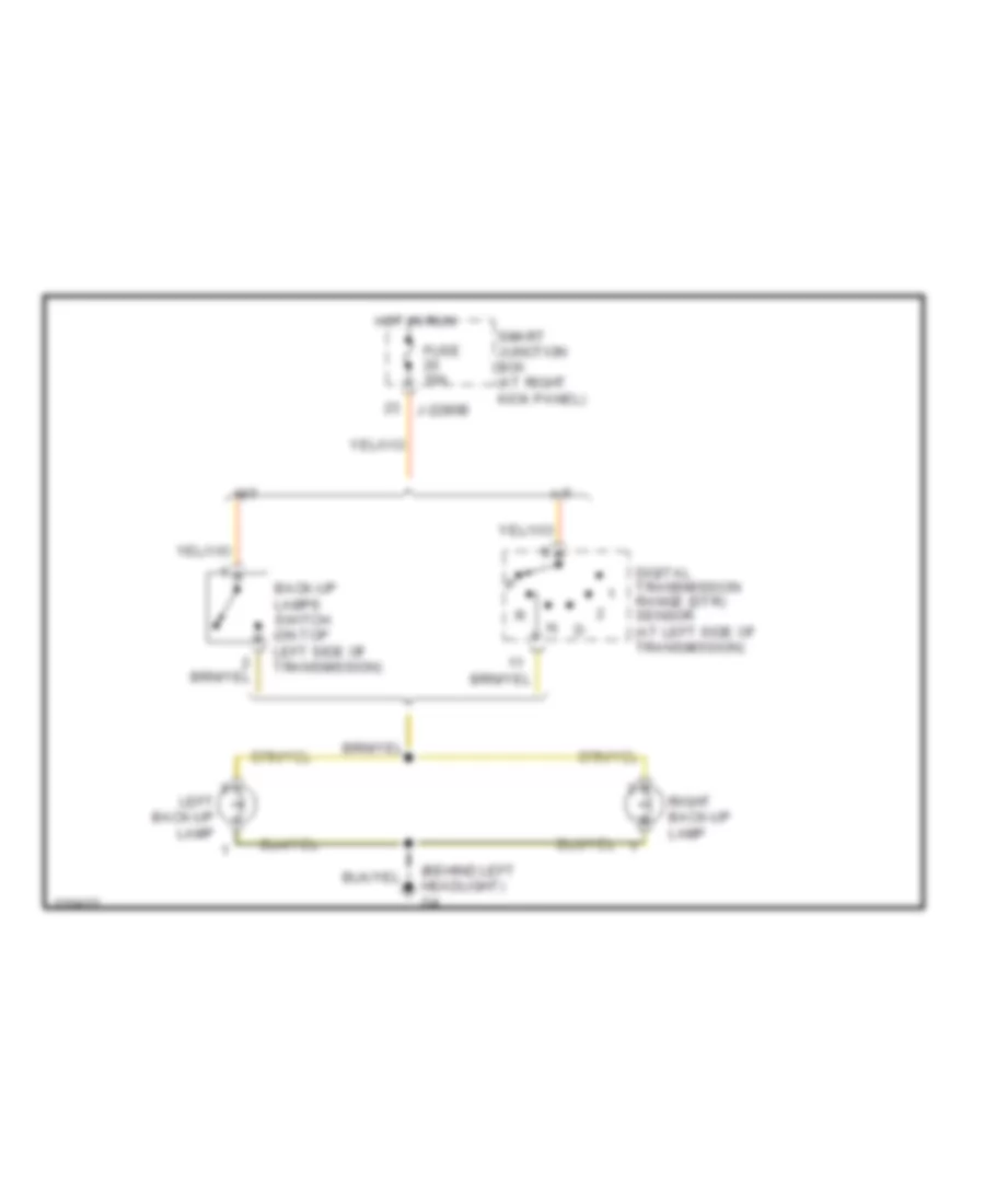
Back-up Lamps Wiring Diagram for Mazda B2007 4000
List of elements for Back-up Lamps Wiring Diagram for Mazda B2007 4000:
- (behind left headlight) g4
- A/t
- Back-up lamps switch (on top left side of transmission)
- Digital transmission range (dtr) sensor (at left side of transmission)
- Fuse 10a
- Hot in run
- J-2280b
- Left back-up lamp
- M/t
- Right back-up lamp
- Smart junction box (at right kick panel)
Exterior Lamps Wiring Diagram (1 of 2) for Mazda B2007 4000
List of elements for Exterior Lamps Wiring Diagram (1 of 2) for Mazda B2007 4000:
- (under left side of dash) indicator flasher relay
- 0918-104
- 0918-105
- 0922-102
- 87a
- Battery junction box (left rear of engine compt)
- Brake pedal position switch (behind left side of dash, on brake pedal support)
- Fuse 10a
- Fuse 15a
- Fuse 20a
- Fuse 7.5a
- G13
- G4 (behind left headlight)
- Hazard
- High mounted stoplamp
- Hot at all times
- Hot in run
- Instrument cluster
- J-2280b
- Left license plate lamp
- Left rear park/stop/turn lamp
- Left turn
- Left turn ind
- Microprocessor
- Multi-function switch
- Normal
- Red
- Right license plate lamp
- Right rear park/stop/turn lamp
- Right turn
- Right turn ind
- Smart junction box (at right kick panel)
Exterior Lamps Wiring Diagram (2 of 2) for Mazda B2007 4000
List of elements for Exterior Lamps Wiring Diagram (2 of 2) for Mazda B2007 4000:
- Connector
- Fuse 10a
- Fuse 20a
- Fuse 30a
- Fuse 5a
- G4 (behind left headlight)
- G5 (at right rear corner of engine compt)
- Head
- Hot at all times
- Interior lights system
- J-2280a
- J-2280b
- J-2280c
- J-2280d
- Left front park/turn lamp
- Left rear turn lamp
- Main light switch
- Micro- processor
- Off
- Park
- Park lamp relay
- Right front park/turn lamp
- Right rear turn lamp
- Smart junction box (at right kick panel)
- Trailer tow
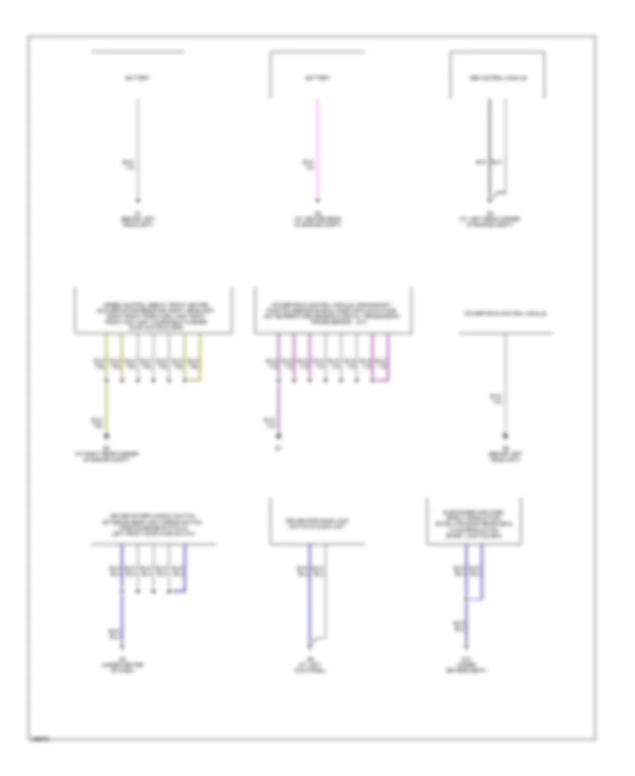
GROUND DISTRIBUTION
Ground Distribution Wiring Diagram (1 of 2) for Mazda B2007 4000
List of elements for Ground Distribution Wiring Diagram (1 of 2) for Mazda B2007 4000:
- (a/t)
- Abs control module
- Battery
- Driver power window switch, exterior rear view mirror switch, parking brake switch & left front door ajar switch
- Driver side door lock switch & audio unit
- G1 (behind left headlight)
- G10 (under driver's seat)
- G2 (at center rear of engine compt)
- G3 (at left rear corner of engine compt)
- G5 (at right rear corner of engine compt)
- G6 (behind left headlight)
- G8 (under center of dash)
- G9 (at left kick panel)
- Powertrain control module
- Powertrain control module, crankshaft position sensor shield, mass air flow/intake air temperature sensor & digital transmission range sensor
- Speed control servo, front heater blower motor resistor, right headlamp, right front park/turn lamp, right front fog lamp, windshield washer pump motor & horn
- Subwoofer amplifier, (early production) satellite radio receiver & (late production) smart junction box
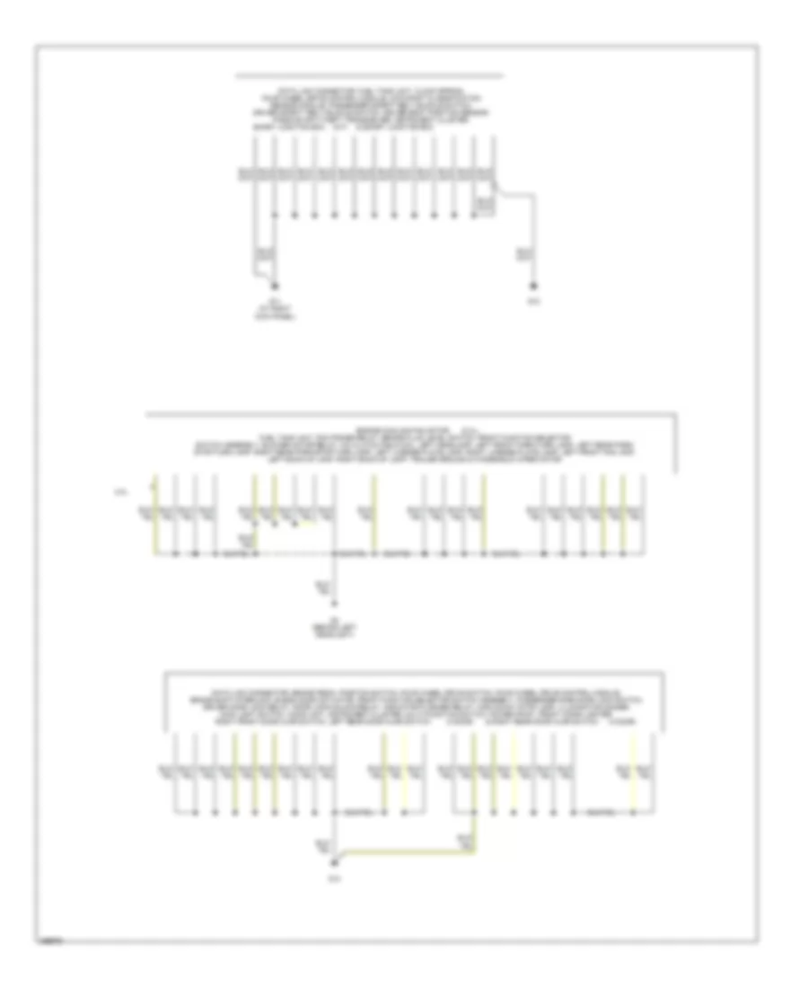
Ground Distribution Wiring Diagram (2 of 2) for Mazda B2007 4000
List of elements for Ground Distribution Wiring Diagram (2 of 2) for Mazda B2007 4000:
- & right rear door ajar switch
- & smart junction box
- (2.3l),
- (4 door)
- (m/t)
- 2.3l
- Data link connector, brake pedal position switch, four wheel drive switch, four wheel drive control module, brake shift interlock, blend door actuator, front function selector switch assembly, passenger side door lock switch, driver door lock relay, door lock/unlock relay, indicator flasher relay, high mount stop lamp, illumination dimmer, main light switch, audio unit, instrument cluster, multi-function switch, power point, front cigar lighter,
- Data link connector, fuel tank unit, clock spring, four wheel drive control module, occupant classification sensor module, passenger safety belt buckle switch, driver safety belt buckle switch, driver seat position sensor, passive anti-theft transceiver, instrument cluster,
- Engine cooling fan motor
- Fuel tank unit, pcm power relay, brake fluid level switch, front function selector switch assembly, blower motor relay, a/c clutch field coil, left headlamp, left front park/turn lamp, left rear park/ stop/turn lamp, right rear park/stop/turn lamp, left license plate lamp, right license plate lamp, left front fog lamp, left back-up lamp, right back-up lamp, trailer ground & windshield wiper motor
- G11 (at right kick panel)
- G12
- G13
- G4 (behind left headlight)
- Right front door ajar switch, left rear door ajar switch
- Smart junction box
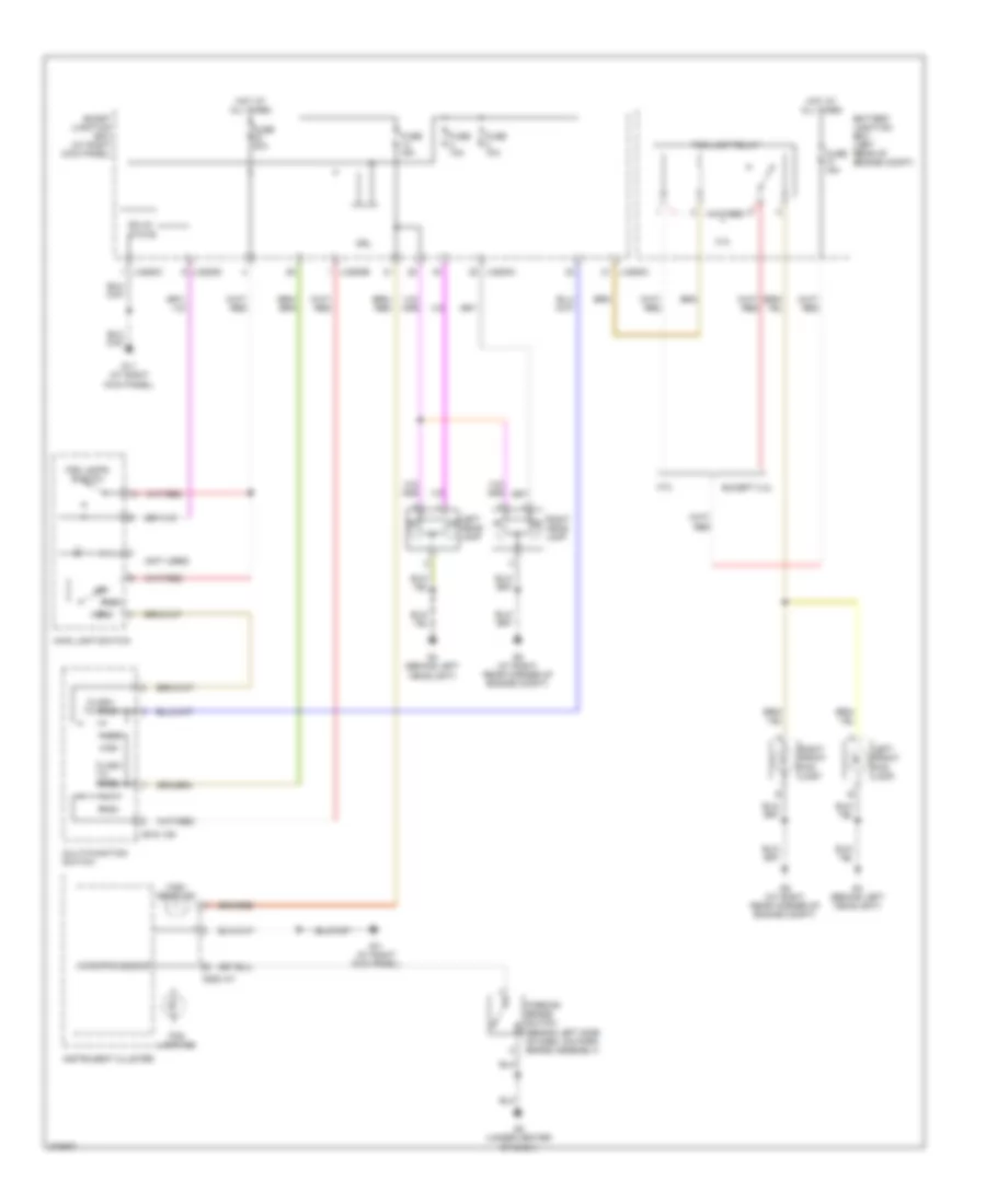
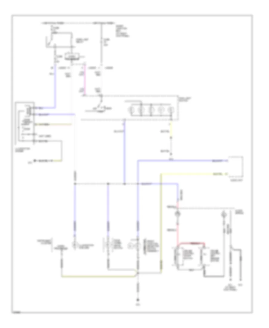
HEADLIGHTS
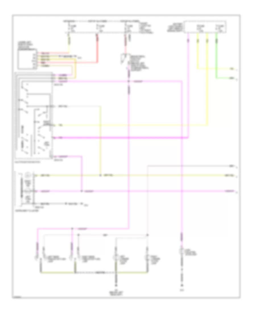
Headlights Wiring Diagram, with DRL for Mazda B2007 4000
List of elements for Headlights Wiring Diagram, with DRL for Mazda B2007 4000:
- (not used)
- 0918-105
- 0922-101
- 2.3l
- Battery junction box (left rear of engine compt)
- Drl
- Except 2.3l
- Flash to pass
- Fog lamp ind
- Fog lamp relay
- Fog lamps switch
- Fuse 10a
- Fuse 15a
- Fuse 30a
- G11 (at right kick panel)
- G4 (behind left headlight)
- G5 (at right rear corner of engine compt)
- G8 (under center of dash)
- Head
- High
- High beam ind
- Hot at all times
- Instrument cluster
- J-2280a
- J-2280b
- J-2280c
- J-2280d
- Left front fog lamp
- Left head- lamp
- Low
- Main light switch
- Microprocessor
- Multi-function switch
- Off
- Park
- Parking brake switch (behind left side of dash, on park brake assembly)
- Right front fog lamp
- Right head- lamp
- Smart junction box (at right kick panel)
- Solid state
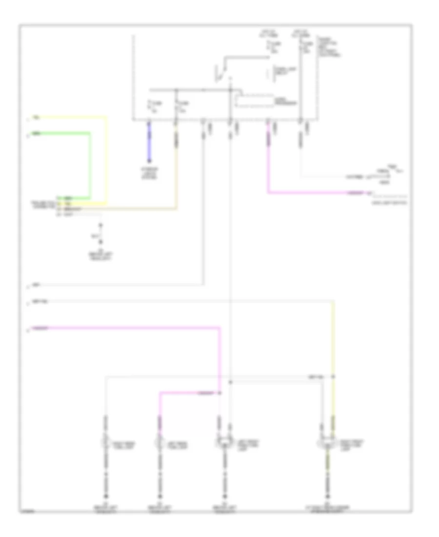
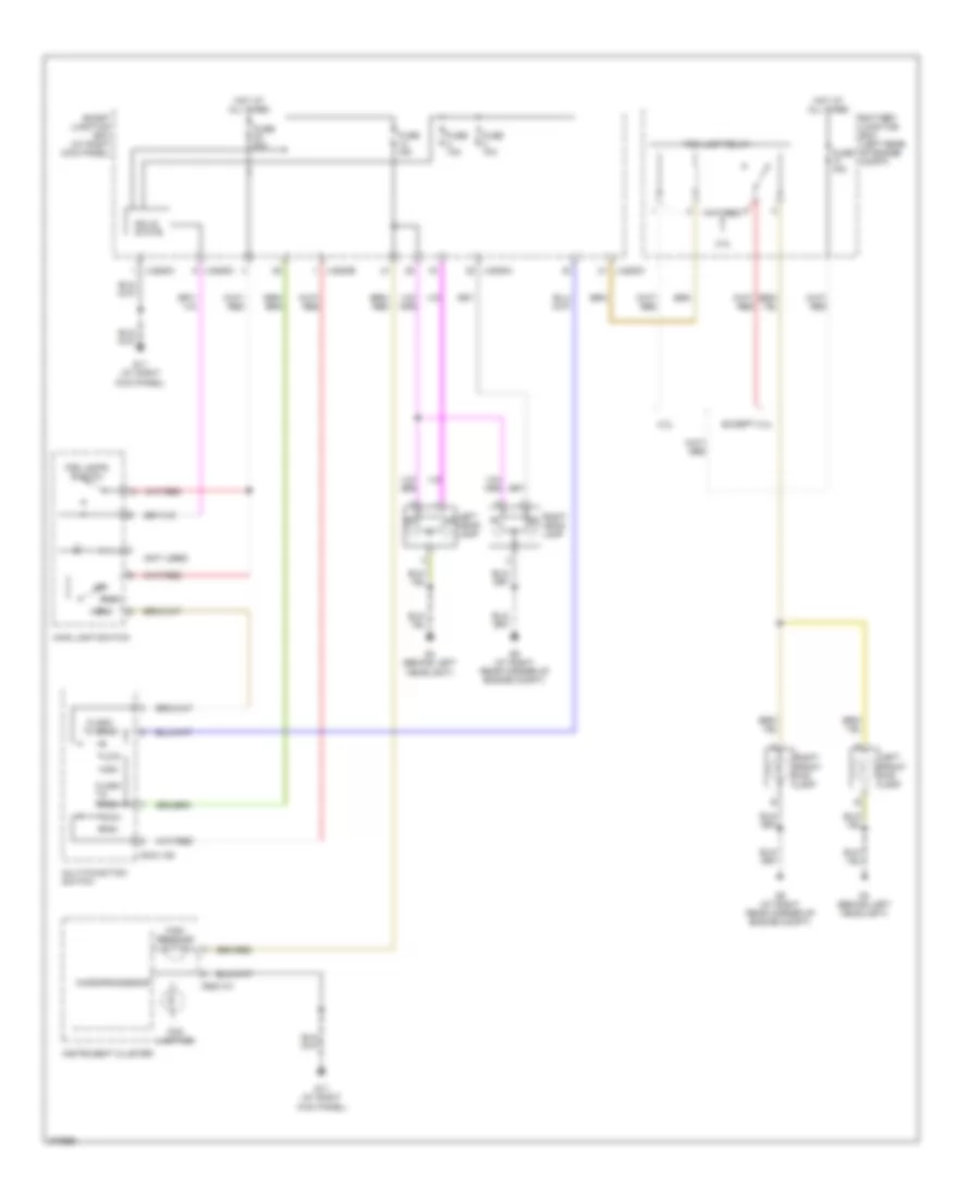
Headlights Wiring Diagram, without DRL for Mazda B2007 4000
List of elements for Headlights Wiring Diagram, without DRL for Mazda B2007 4000:
- (not used)
- 0918-105
- 0922-101
- 2.3l
- Battery junction box (left rear of engine compt)
- Except 2.3l
- Flash to pass
- Fog lamp ind
- Fog lamp relay
- Fog lamps switch
- Fuse 10a
- Fuse 15a
- Fuse 30a
- G11 (at right kick panel)
- G4 (behind left headlight)
- G5 (at right rear corner of engine compt)
- Head
- High
- High beam ind
- Hot at all times
- Instrument cluster
- J-2280a
- J-2280b
- J-2280c
- J-2280d
- Left front fog lamp
- Left head- lamp
- Low
- Main light switch
- Microprocessor
- Multi-function switch
- Off
- Park
- Right front fog lamp
- Right head- lamp
- Smart junction box (at right kick panel)
- Solid state
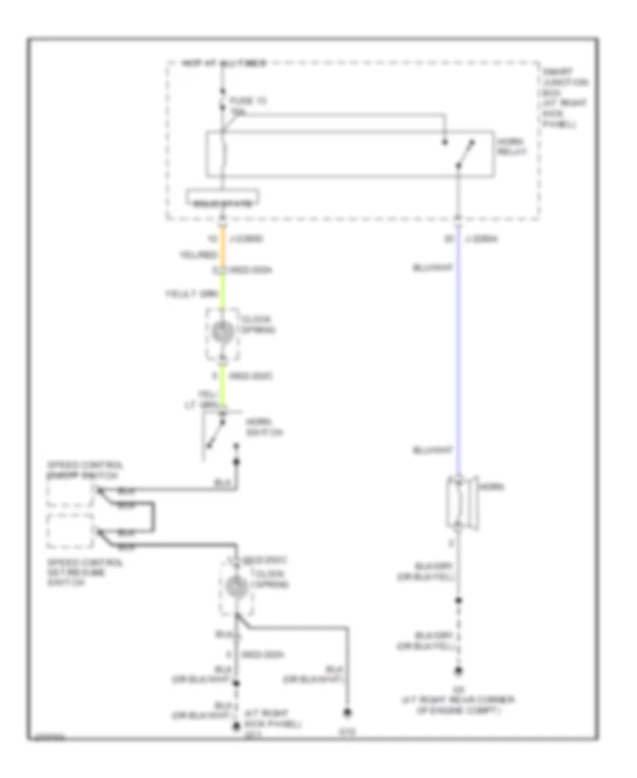
HORN
Horn Wiring Diagram for Mazda B2007 4000
List of elements for Horn Wiring Diagram for Mazda B2007 4000:
- (at right kick panel) g11
- 0922-202a
- 0922-202c
- Clock spring
- Fuse 13 15a
- G12
- G5 (at right rear corner of engine compt)
- Horn
- Horn relay
- Horn switch
- Hot at all times
- J-2280a
- J-2280d
- Smart junction box (at right kick panel)
- Solid state
- Speed control on/off switch
- Speed control set/resume switch
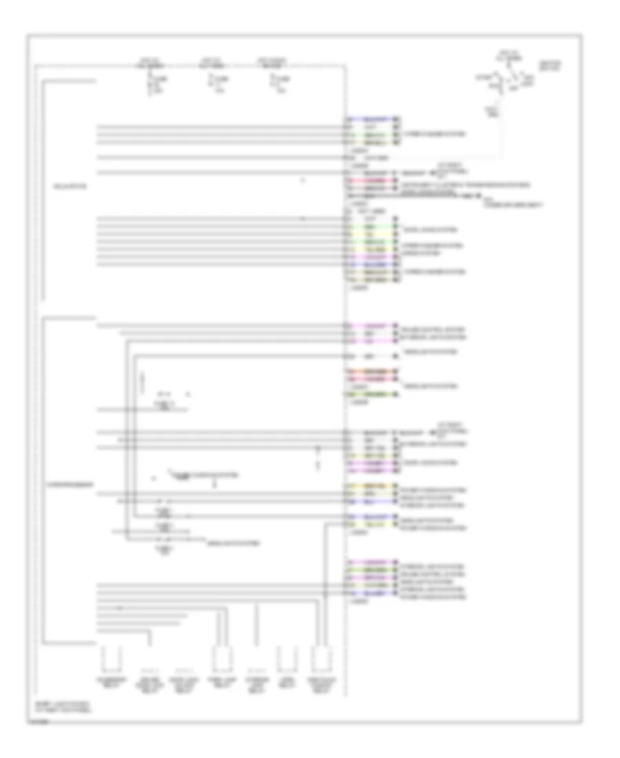
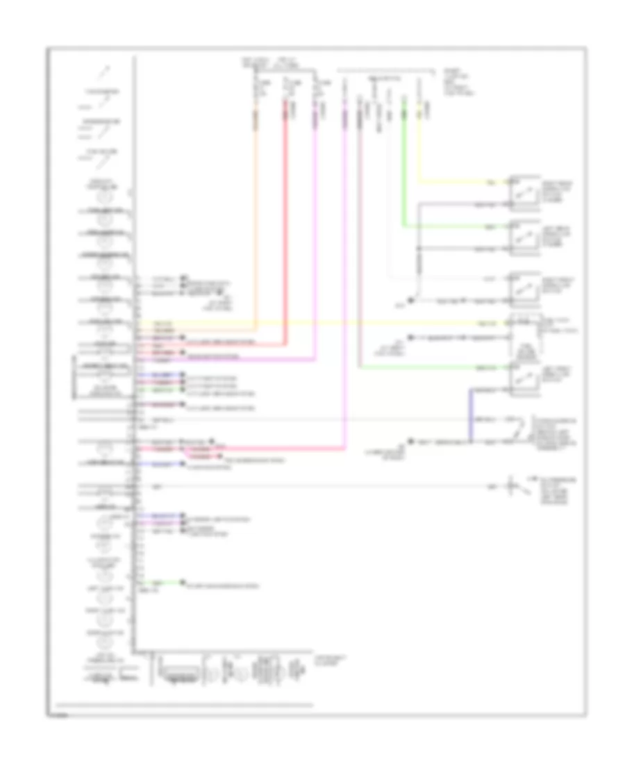
INSTRUMENT CLUSTER
Instrument Cluster Wiring Diagram for Mazda B2007 4000
List of elements for Instrument Cluster Wiring Diagram for Mazda B2007 4000:
- (not used)
- 0922-101
- 0922-102
- 4wd ind
- 4wd low ind
- Abs ind
- Air bag ind
- Anti-lock brakes system
- Anti-theft system
- Brake ind fluid/park brake
- Charge ind
- Check engine ind
- Coolant temp gauge
- Door ajar ind
- Exterior lights system
- Failsafe cooling ind
- Fog lamps ind
- Fuel cap ind
- Fuel gauge
- Fuel gauge sensor
- Fuel tank unit (in fuel tank)
- Fuse 10a
- Fuse 5a
- G11 (at right kick panel)
- G13
- G8 (under center of dash)
- Headlights system
- High beam ind
- Hot at all times
- Hot in run or start
- Illumination (6 bulbs)
- Ind control speed
- Instrument cluster
- Interior lights system
- J-2280b
- J-2280c
- J-2280d
- Left front door ajar switch
- Left rear door ajar switch (4 door)
- Left turn ind
- Low oil pressure ind
- Microprocessor
- O/d off ind
- Odometer/ tripmeter
- Oil pressure switch (on lower left rear of engine)
- On ind anti-theft
- Parking brake switch (behind left side of dash, on park brake assembly)
- Prndl
- Red
- Right front door ajar switch
- Right rear door ajar switch (4 door)
- Right turn ind
- Safety belt ind
- Smart junction box (at right kick panel)
- Solid state
- Speedometer
- Starting/charging system
- Tachometer
- Transmissions system
- Warning chime
- Warning system
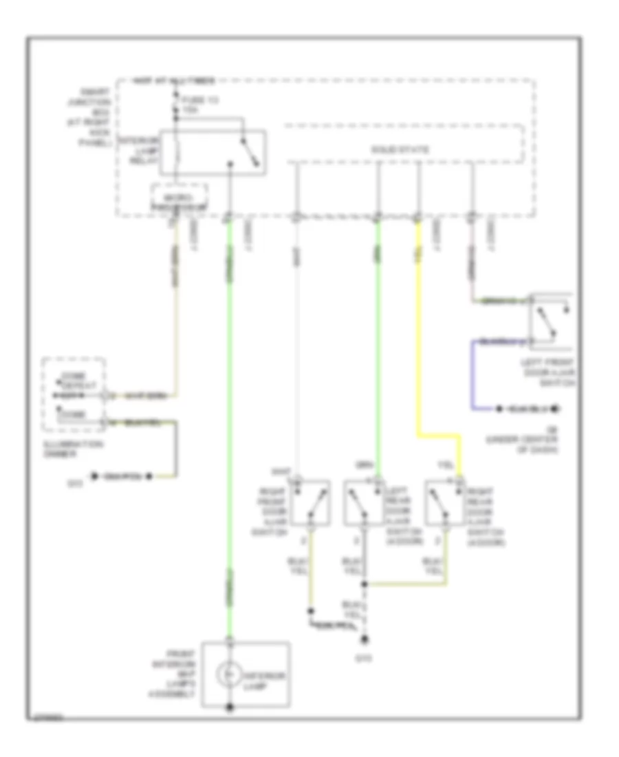
INTERIOR LIGHTS
Courtesy Lamps Wiring Diagram for Mazda B2007 4000
List of elements for Courtesy Lamps Wiring Diagram for Mazda B2007 4000:
- Dome
- Dome defeat off
- Front interior/ map lamps assembly
- Fuse 13 15a
- G13
- G8 (under center of dash)
- Hot at all times
- Illumination dimmer
- Interior lamp
- Interior lamp relay
- J-2280c
- J-2280d
- Left front door ajar switch
- Left rear door ajar switch (4 door)
- Micro- processor
- Right front door ajar switch
- Right rear door ajar switch (4 door)
- Smart junction box (at right kick panel)
- Solid state
Instrument Illumination Wiring Diagram for Mazda B2007 4000
List of elements for Instrument Illumination Wiring Diagram for Mazda B2007 4000:
- (not used)
- 0922-202a
- 0922-202c
- 30a
- Audio unit
- Clock spring
- Cruise control on/off switch
- Cruise control set/ resume switch
- Dome
- Dome defeat off
- Four- wheel drive switch
- Front function selector switch assembly
- Fuse
- Fuse 20a
- Fuse 5a
- G11 (at right kick panel)
- G12
- G13
- Head
- Hot at all times
- Illumination
- Illumination (6 bulbs)
- Illumination dimmer
- Instrument cluster
- J-2280b
- J-2280c
- J-2280d
- Main light switch
- Micro- processor
- Off
- Park
- Park lamp relay
- Smart junction box (at right kick panel)
- Solid
- State
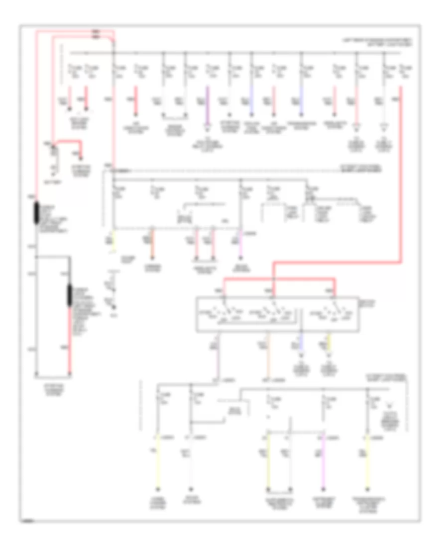
POWER DISTRIBUTION
Power Distribution Wiring Diagram (1 of 2) for Mazda B2007 4000
List of elements for Power Distribution Wiring Diagram (1 of 2) for Mazda B2007 4000:
- (at right kick panel) smart junction box
- (left rear of engine compartment) battery junction box
- Acc
- Air conditioning system
- Anti-lock brakes system
- Battery
- C2280a
- Cooling fans system
- Door lock/ unlock relay
- Driver door lock relay
- Drl
- Engine controls system
- Fuse 10a
- Fuse 15a
- Fuse 20a
- Fuse 30a
- Fuse 40a
- Fuse 50a
- Fuse 5a
- G13
- Headlights system
- Ignition switch
- Instrument cluster system
- J-2280a
- J-2280b
- J-2280c
- Lock
- Mirrors system
- Nca
- Off
- Park lamp relay
- Power point
- Red
- Run
- Solid state
- Sound systems
- Start
- Starting/ charging system
- To fuse 17 (diagram 2 of 2)
- To fuse 22 (diagram 2 of 2)
- To fuse 27 (diagram 2 of 2)
- To fuse 29 (diagram 2 of 2)
- To pcm power relay (diagram 2 of 2)
- To ptc circuit breaker (diagram 2 of 2)
- Transmissions & instrument cluster systems
- Transmissions system
- Wiper/ washer system
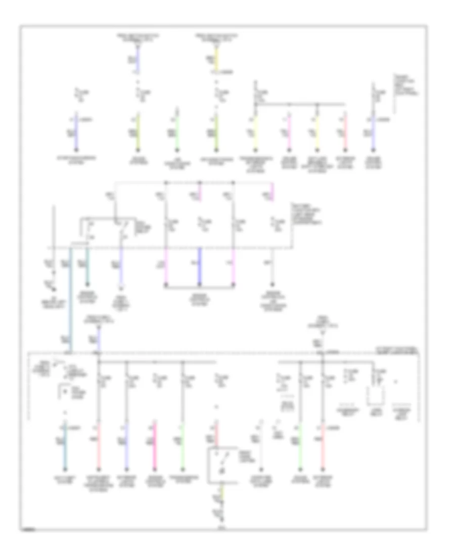
Power Distribution Wiring Diagram (2 of 2) for Mazda B2007 4000
List of elements for Power Distribution Wiring Diagram (2 of 2) for Mazda B2007 4000:
- (at right kick panel) smart junction box
- (not used)
- Accessory relay
- Air conditioning system
- Anti-lock brakes & shift interlock systems
- Anti-theft system
- Battery junction box (left rear of engine compartment)
- Computer data lines system
- Cruise control system
- Engine controls & air conditioning systems
- Engine controls system
- Exterior lights system
- From fuse 10 (diagram 1 of 2)
- From fuse 11 (diagram 1 of 1)
- From fuse 3 (diagram 1 of 2)
- From fuse 5 (diagram 1 of 2)
- From ignition switch (diagram 1 of 2)
- Front cigar lighter
- Fuse 10a
- Fuse 15a
- Fuse 20a
- Fuse 2a
- Fuse 30a
- Fuse 5a
- G13
- G4 (behind left headlight)
- Horn relay
- Instrument cluster & transmissions systems
- Interior lamp relay
- J-2280a
- J-2280b
- J-2280c
- Pcm power diode
- Pcm power relay
- Ptc circuit breaker 1a
- Red
- Smart junction box (at right kick panel)
- Solid state
- Sound systems
- Starting/charging system
- Transmissions & exterior lights systems
- Transmissions system
POWER DOOR LOCKS
Power Door Locks Wiring Diagram for Mazda B2007 4000
List of elements for Power Door Locks Wiring Diagram for Mazda B2007 4000:
- (not used)
- Door lock/
- Driver door lock relay
- Driver side door lock switch
- Exterior lights system
- Fuse 15a
- Fuse 20a
- Fuse 5a
- G11 (at right kick panel)
- G13
- G8 (under center of dash)
- G9 (at left kick panel)
- Horn relay
- Horns system
- Hot at all times
- Instrument cluster system
- Instrument panel dimming module (left side of dash)
- Interior lights system
- J-2280a
- J-2280b
- J-2280c
- J-2280d
- Left front door ajar switch
- Left front door lock actuator (at rear of left front door)
- Left rear door ajar switch (4 door)
- Lock
- Microprocessor
- Park lamp relay
- Passenger side door lock switch
- Right front door ajar switch
- Right front door lock actuator (at rear of right front door)
- Right rear door ajar switch (4 door)
- Smart junction box (at right kick panel)
- Solid state
- Unlock
- Unlock relay
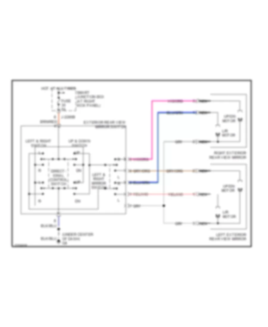
POWER MIRRORS
Power Mirrors Wiring Diagram for Mazda B2007 4000
List of elements for Power Mirrors Wiring Diagram for Mazda B2007 4000:
- (under center of dash) g8
- Direct- ional control switch
- Exterior rear view mirror switch
- Fuse 5a
- Hot at all times
- J-2280b
- L/r motor
- Left & right mirror switch
- Left & right switch
- Left exterior rear view mirror
- Nca
- Right exterior rear view mirror
- Smart junction box (at right kick panel)
- Up & down switch
- Up/dn motor
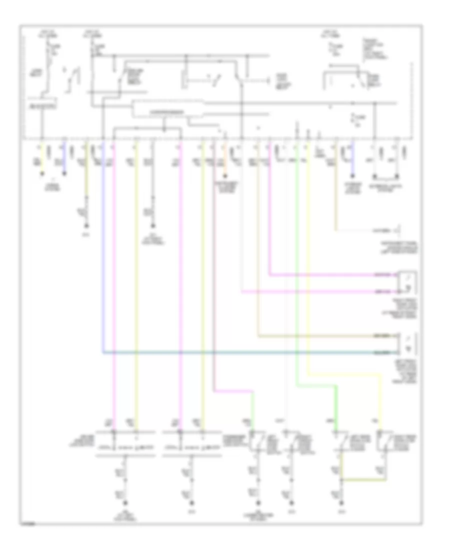
POWER WINDOWS
Power Windows Wiring Diagram for Mazda B2007 4000
List of elements for Power Windows Wiring Diagram for Mazda B2007 4000:
- (in left front door) driver power window motor
- (in right front door)
- 11a
- Accessory relay
- Down
- Driver power window switch
- Front passenger side power window motor
- Fuse 30a
- G11 (at right kick panel)
- G8 (under center of dash)
- Hot at all times
- J-2280c
- J-2280d
- Left
- Microprocessor
- Off
- One-touch window relay
- Passenger side front power window switch
- Ptc circuit breaker
- Rest
- Right
- Smart junction box (sjb) (at right kick panel)
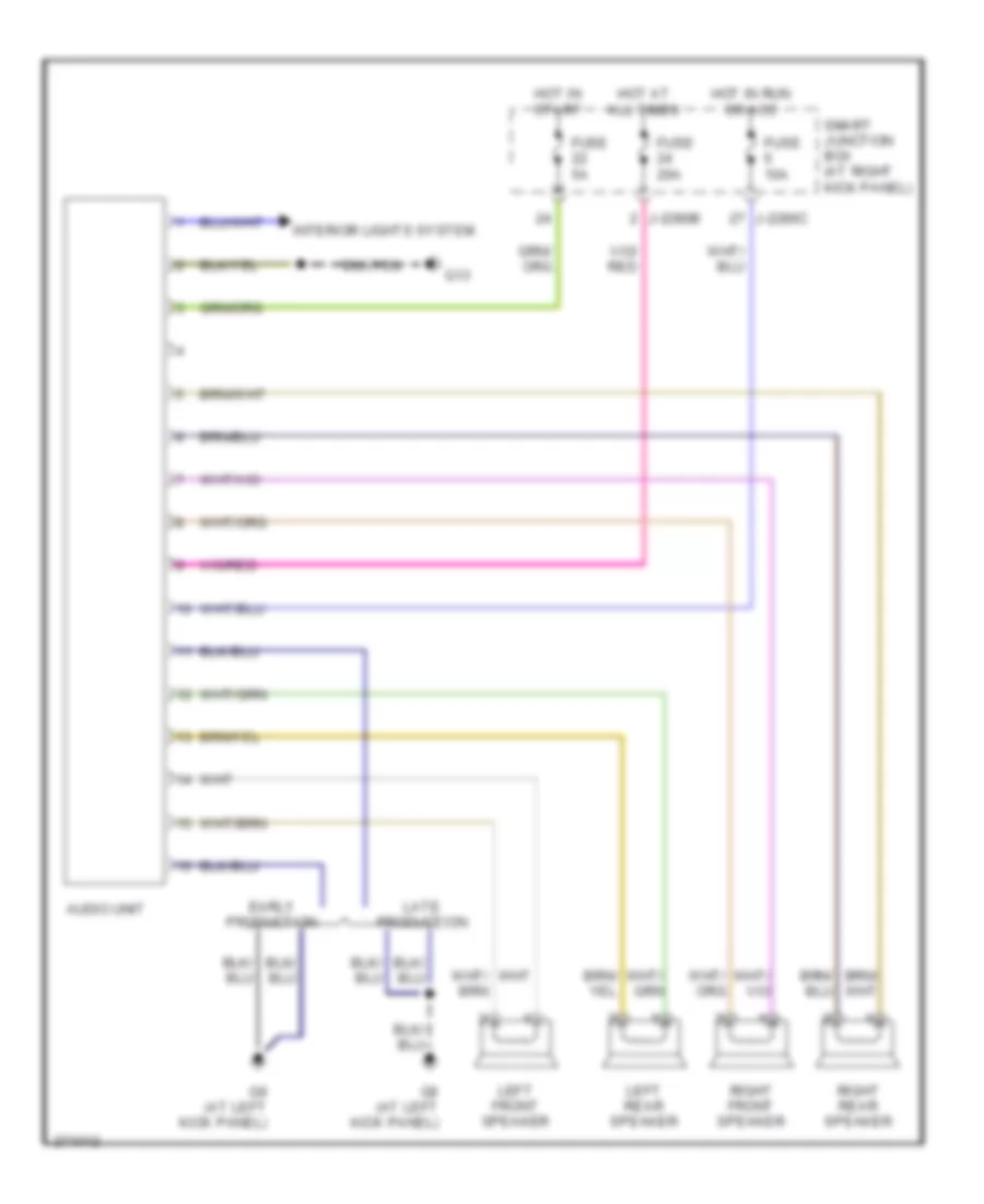
RADIO
Base Radio Wiring Diagram for Mazda B2007 4000
List of elements for Base Radio Wiring Diagram for Mazda B2007 4000:
- Audio unit
- Early production
- Fuse 10a
- Fuse 20a
- Fuse 5a
- G13
- G9 (at left kick panel)
- Hot at all times
- Hot in run or acc
- Hot in start
- Interior lights system
- J-2280b
- J-2280c
- Late production
- Left front speaker
- Left rear speaker
- Right front speaker
- Right rear speaker
- Smart junction box (at right kick panel)
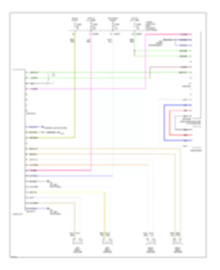
Premium Radio Wiring Diagram, Early Production for Mazda B2007 4000
List of elements for Premium Radio Wiring Diagram, Early Production for Mazda B2007 4000:
- 0920-201a
- 0920-201b
- 0920-208a
- 0920-208b
- Audio unit
- Fuse 10a
- Fuse 15a
- Fuse 20a
- Fuse 5a
- G10 (under driver's seat)
- G13
- G9 (at left kick panel)
- Hot at all times
- Hot in run or acc
- Hot in start
- Interior lights system
- J-2280b
- J-2280c
- Left front speaker
- Left rear speaker
- Nca
- Red
- Right front speaker
- Right rear speaker
- Smart junction box (at right kick panel)
- Subwoofer
- Subwoofer amplifier (w/ audiophile)
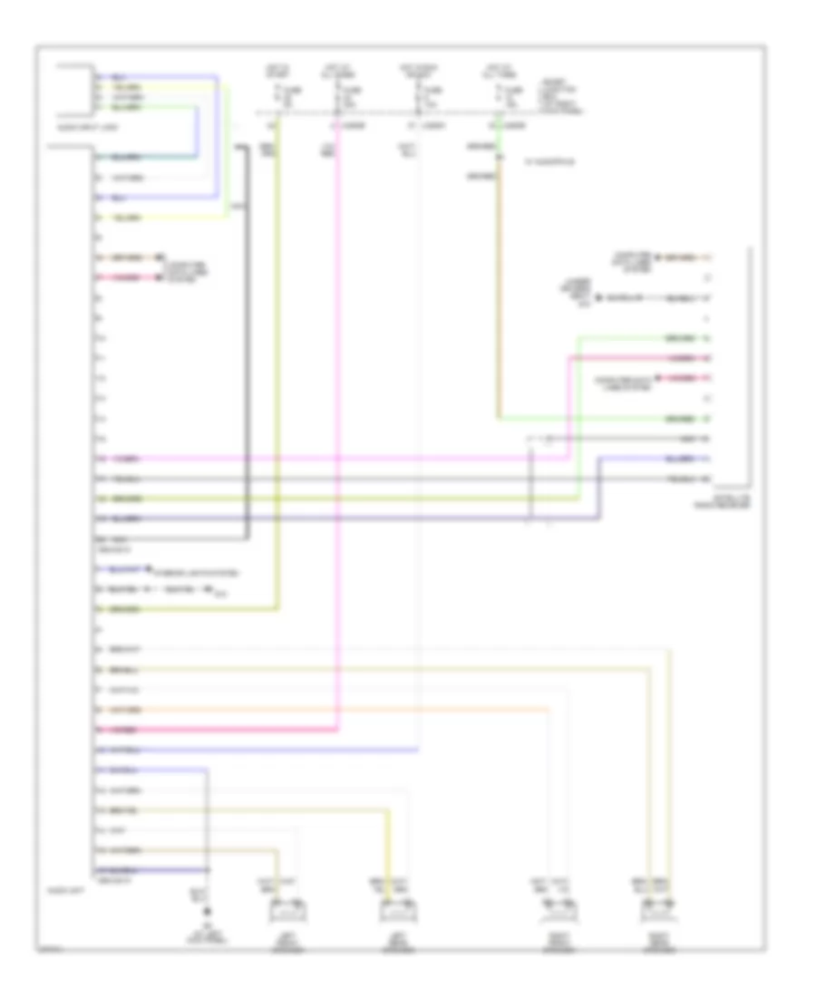
Premium Radio Wiring Diagram, Late Production for Mazda B2007 4000
List of elements for Premium Radio Wiring Diagram, Late Production for Mazda B2007 4000:
- (under driver's seat) g10
- 0920-201a
- 0920-201c
- Audio input jack
- Audio unit
- Computer data lines system
- Fuse 10a
- Fuse 15a
- Fuse 20a
- Fuse 5a
- G13
- G9 (at left kick panel)
- Hot at all times
- Hot in run or acc
- Hot in start
- Interior lights system
- J-2280b
- J-2280c
- Left front speaker
- Left rear speaker
- Nca
- Right front speaker
- Right rear speaker
- Satellite radio reciever
- Smart junction box (at right kick panel)
- W/ audiophile
SHIFT INTERLOCK
Shift Interlock Wiring Diagram for Mazda B2007 4000
List of elements for Shift Interlock Wiring Diagram for Mazda B2007 4000:
- Brake pedal position switch (behind left side of dash, on brake pedal support)
- Brake shift interlock (behind left side of dash)
- Fuse 20 10a
- Fuse 32 5a
- G13
- Hot at all times
- Hot in run
- J-2280b
- Smart junction box (at right kick panel)
- Solid state
STARTING/CHARGING
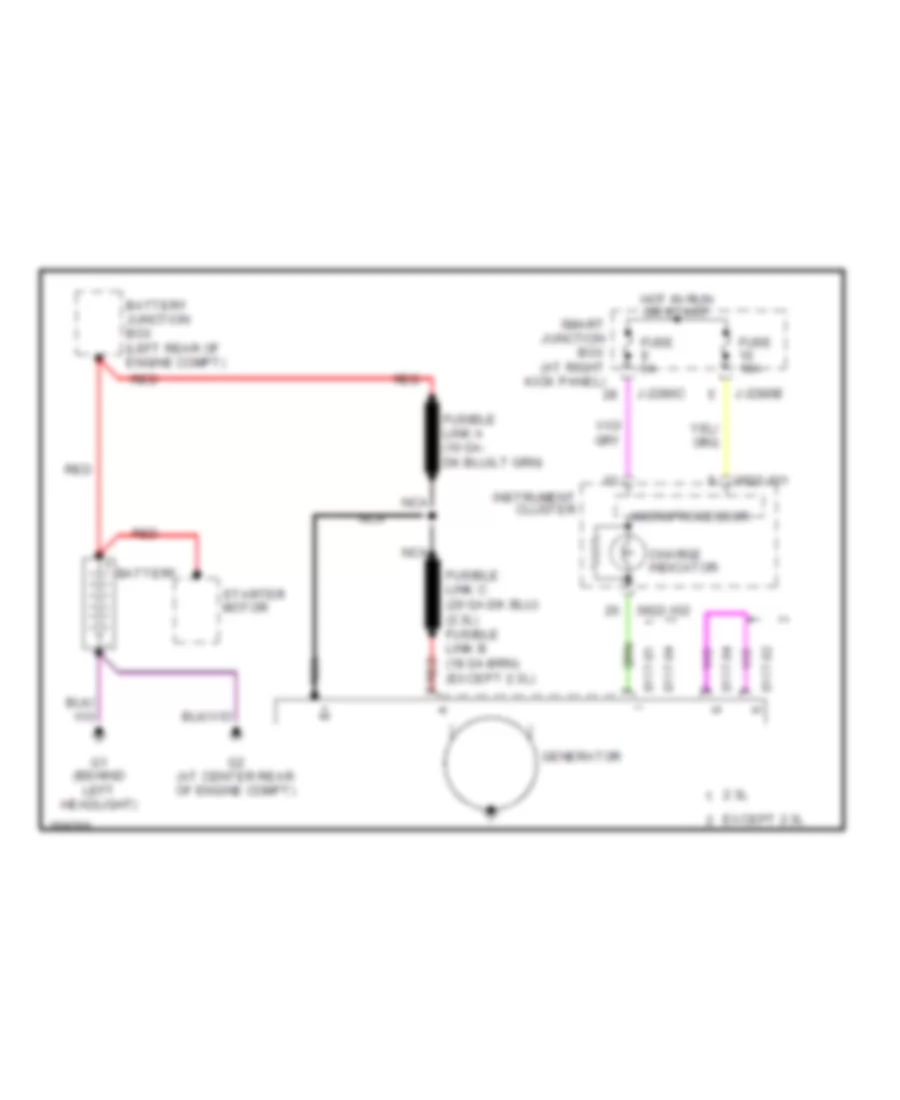
Charging Wiring Diagram for Mazda B2007 4000
List of elements for Charging Wiring Diagram for Mazda B2007 4000:
- 0117-01
- 0117-02
- 0117-04
- 0922-101
- 0922-102
- 2.3l
- Battery
- Battery junction box (left rear of engine compt)
- Charge indicator
- Except 2.3l
- Fuse 10a
- Fuse 5a
- G1 (behind left headlight)
- G2 (at center rear of engine compt)
- Generator
- Hot in run or start
- Instrument cluster
- J-2280b
- J-2280c
- Microprocessor
- Nca
- Red
- Smart junction box (at right kick panel)
- Starter motor
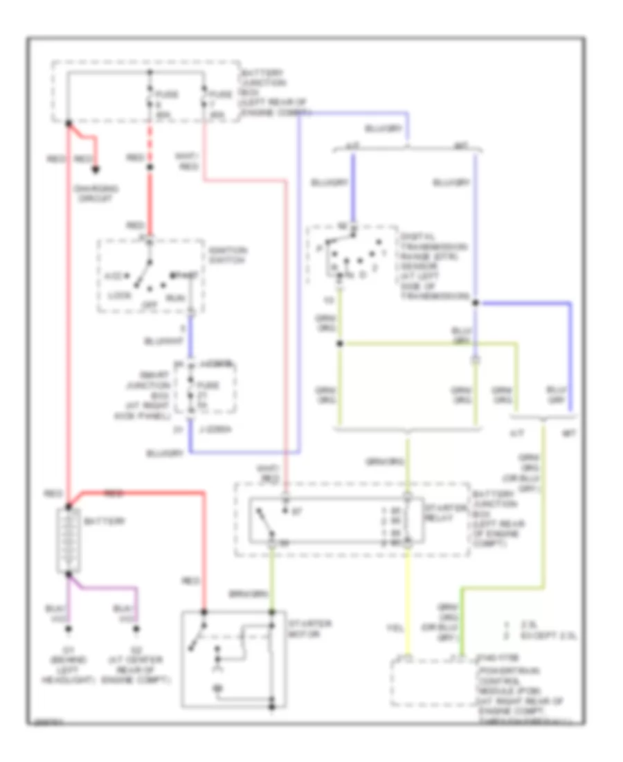
Starting Wiring Diagram for Mazda B2007 4000
List of elements for Starting Wiring Diagram for Mazda B2007 4000:
- 0140-175b
- 2.3l
- A/t
- Acc
- Battery
- Battery junction box (left rear of engine compt)
- Charging circuit
- Digital transmission range (dtr) sensor (at left side of transmission)
- Except 2.3l
- Fuse 40a
- Fuse 5a
- G1 (behind left headlight)
- G2 (at center rear of engine compt)
- Ignition switch
- J-2280a
- J-2280b
- Lock
- M/t
- Off
- Powertrain control module (pcm) (at right rear of engine compt, through firewall)
- Red
- Run
- Smart junction box (at right kick panel)
- Start
- Starter motor
- Starter relay
SUPPLEMENTAL RESTRAINTS
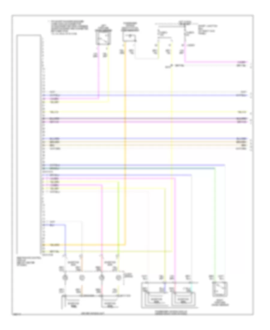
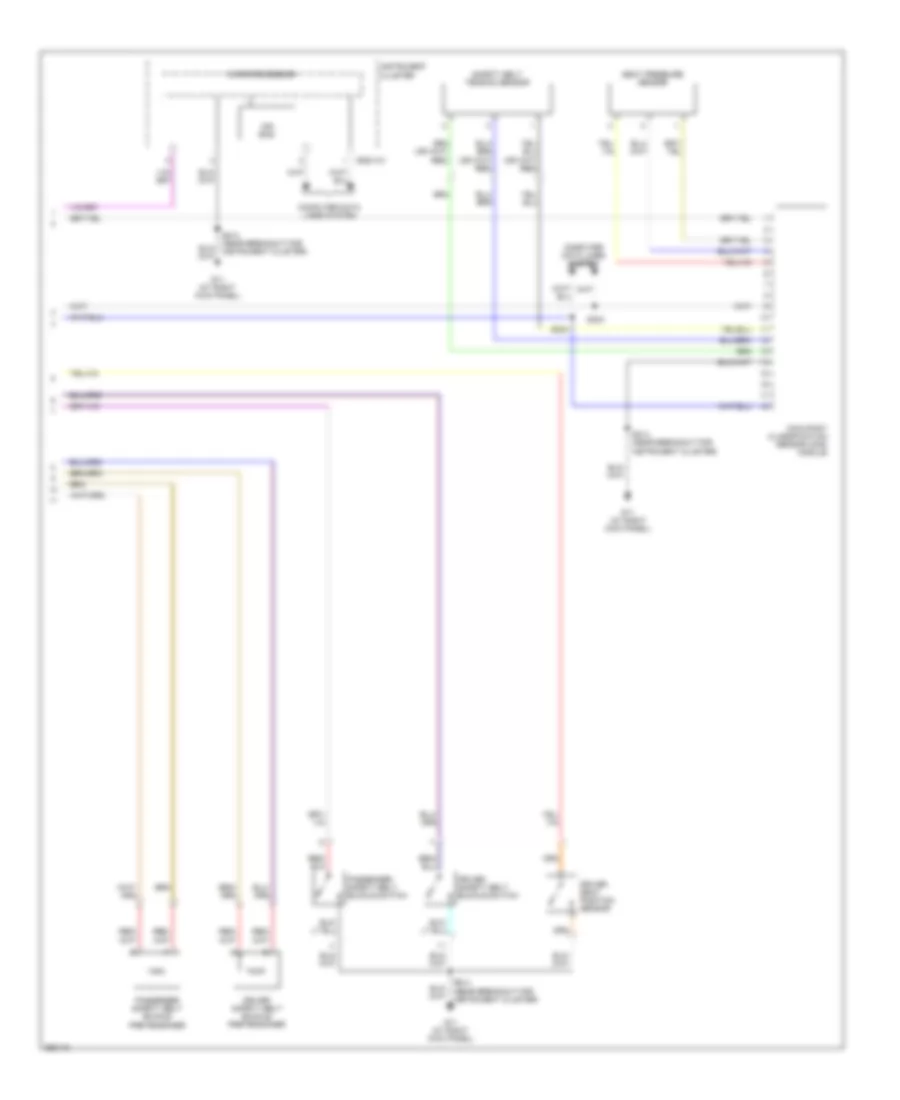
Supplemental Restraints Wiring Diagram (1 of 2) for Mazda B2007 4000
List of elements for Supplemental Restraints Wiring Diagram (1 of 2) for Mazda B2007 4000:
- 0810-101a
- 0810-101b
- 0810-103a
- 0810-103b
- Clock spring
- Driver air bag unit
- Fuse 8 10a
- Fuse 9 5a
- Hot in run or start
- J-2280c
- Left forward crash sensor
- Passenger air bag deactivation (pad) indicator
- Passenger air bag module (behind right side of dash)
- Pin shorting bars engaged when module connector is disconnected from harness (shorting bars are connected between pins: 1-2, 3-4, 5-6 & 15-16 101b)
- Restraints control module (below center of dash)
- Right forward crash sensor
- S219
- Shorting bar
- Smart junction box (at right kick panel)
Supplemental Restraints Wiring Diagram (2 of 2) for Mazda B2007 4000
List of elements for Supplemental Restraints Wiring Diagram (2 of 2) for Mazda B2007 4000:
- 0922-101
- Air bag
- Computer data lines system
- Driver safety belt buckle pretensioner
- Driver safety belt buckle switch
- Driver seat position sensor
- G11 (at right kick panel)
- Instrument cluster
- Microprocessor
- Occupant classification sensor (ocs) module
- Passenger safety belt buckle pretensioner
- Passenger safety belt buckle switch
- S214 (near breakout for instrument cluster)
- S303
- S304
- Safety belt tension sensor
- Seat pressure sensor
TRANSMISSION
4WD Wiring Diagram for Mazda B2007 4000
List of elements for 4WD Wiring Diagram for Mazda B2007 4000:
- (at left side of transmission) (a/t) digital transmission range (dtr) sensor
- (behind left side of dash, on brake pedal support) brake pedal position switch
- 0318-02
- 0318-03
- 0922-101
- 0922-102
- 4wd ind
- 4wd low ind
- Battery junction box (left rear of engine compt)
- Body computer system
- Computer data lines system
- Door ajar ind
- Four-wheel drive control module
- Four-wheel drive switch
- Fuse 10a
- Fuse 15a
- Fuse 20a
- Fuse 5a
- G11 (at right kick panel)
- G13
- Hot at all times
- Hot in run or start
- Illum
- Instrument cluster
- Interior lights system
- J-2280b
- Microprocessor
- Nca
- Neutral tow indicator
- Off
- Red
- Shift motor
- Shift motor sensor
- Smart junction box (at right kick panel)
- Transfer case assembly
A/T Wiring Diagram (1 of 2) for Mazda B2007 4000
List of elements for A/T Wiring Diagram (1 of 2) for Mazda B2007 4000:
- (on end of transmission selector lever) transmission control switch (tcs) (od on/off)
- 0140-175b
- 0140-175e
- 0140-175t
- 5r44e transmission (at left side of transmission)
- Brake pedal position switch (behind left side of dash, on brake pedal support)
- Computer data lines system
- Electronic pressure control (epc) solenoid
- Engine controls system
- Fuse 10a
- Fuse 5a
- G13
- Hot at all times
- Hot in run
- Hot in run or start
- Intermediate shaft speed (iss) sensor (at left side of transmission)
- J-2280a
- J-2280b
- Nca
- Output shaft speed (oss) sensor (at left rear of transmission)
- Pcm power diode
- Powertrain control module (pcm) (at right rear of engine compartment, through firewall)
- Ptc circuit breaker 1a
- Shift solenoids
- Smart box junction (at right kick panel)
- Torque converter clutch (tcc) solenoid
- Transmission fluid temperature (tft) sensor
- Turbine shaft speed (tss) sensor
A/T Wiring Diagram (2 of 2) for Mazda B2007 4000
List of elements for A/T Wiring Diagram (2 of 2) for Mazda B2007 4000:
- (on throttle body assembly) throttle position (tp) sensor
- 0922-101
- Battery junction box (left rear of engine compt)
- Check engine ind
- Computer data lines system
- Digital transmission range (dtr) sensor (at left side of transmission)
- Engine controls system
- Engine coolant temperature (ect) sensor (on top front center of engine)
- Fuse 10a
- Fuse 30a
- G4 (behind left headlight)
- Hot at all times
- Instrument cluster
- Microprocessor
- O/d off ind
- Pcm power relay
- Prndl
WARNING SYSTEMS
Warning Systems Wiring Diagram for Mazda B2007 4000
List of elements for Warning Systems Wiring Diagram for Mazda B2007 4000:
- 0810-101a
- 0922-101
- 0922-102
- Can+
- Can-
- Computer data lines system
- Door ajar ind
- Driver safety belt buckle switch
- Fuse 10a
- Fuse 30a
- Fuse 5a
- G11 (at right kick panel)
- G13
- G8 (under center of dash)
- Ground
- Head
- Hot at all times
- Hot in start or run
- Ignition key switch
- Instrument cluster
- J-2280b
- J-2280c
- J-2280d
- Left front door ajar switch
- Main light switch
- Micro- processor
- Microprocessor
- Off
- Park
- Red
- Restraint control module (below center of dash)
- Safety belt ind
- Smart junction box (sjb) (at right kick panel)
- Solid state
- Sw in
- Vbatt
- Vpwr
- Warning chime
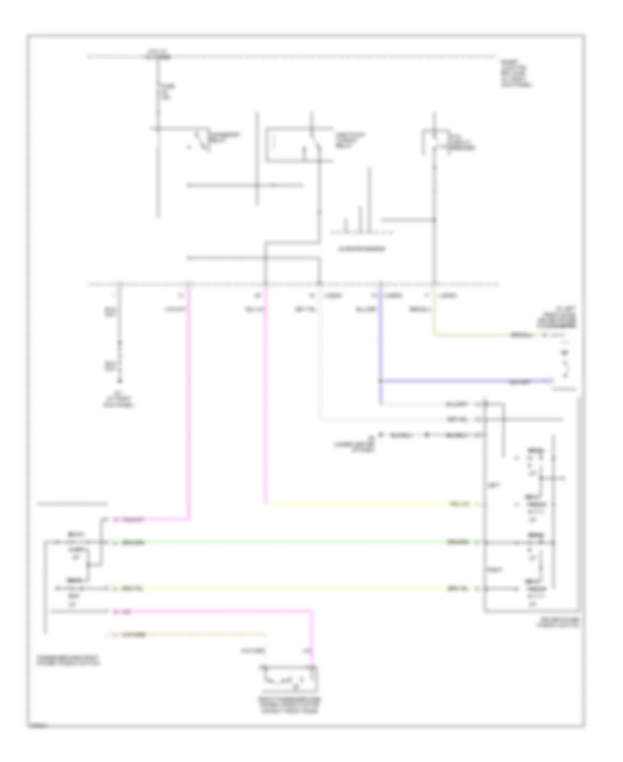
WIPER/WASHER
Wiper/Washer Wiring Diagram for Mazda B2007 4000
List of elements for Wiper/Washer Wiring Diagram for Mazda B2007 4000:
- 1. interval 1 2. interval 2 3. interval 3 4. interval 4 5. interval 5
- Battery junction box (bjb) (left rear of engine compartment)
- Circuit breaker
- Fuse 5 30a
- G13
- G4 (behind left headlight)
- G5 (at right rear corner of engine compartment)
- Hot in run or acc
- J-2280a
- J-2280d
- Low
- Mist
- Multi-function switch
- Off
- Park
- Park sense
- Run
- Run/park relay control
- Smart junction box (sjb) (at right kick panel)
- Vref
- Wash
- Washer pump relay control j-2280a
- Windshield washer pump motor (at right rear of engine compartment)
- Windshield washer relay
- Windshield wiper motor (top left center of firewall)
- Wiper high/low relay
- Wiper high/low relay control
- Wiper run/ park relay