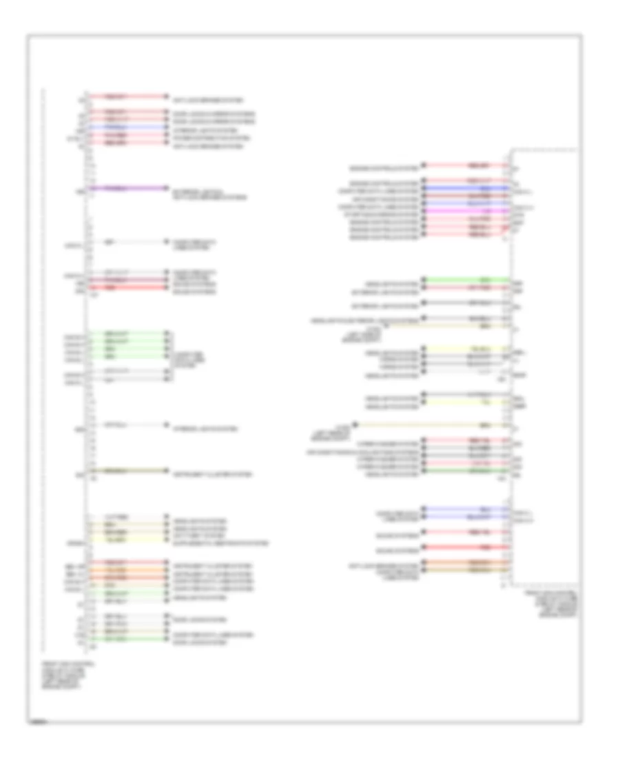
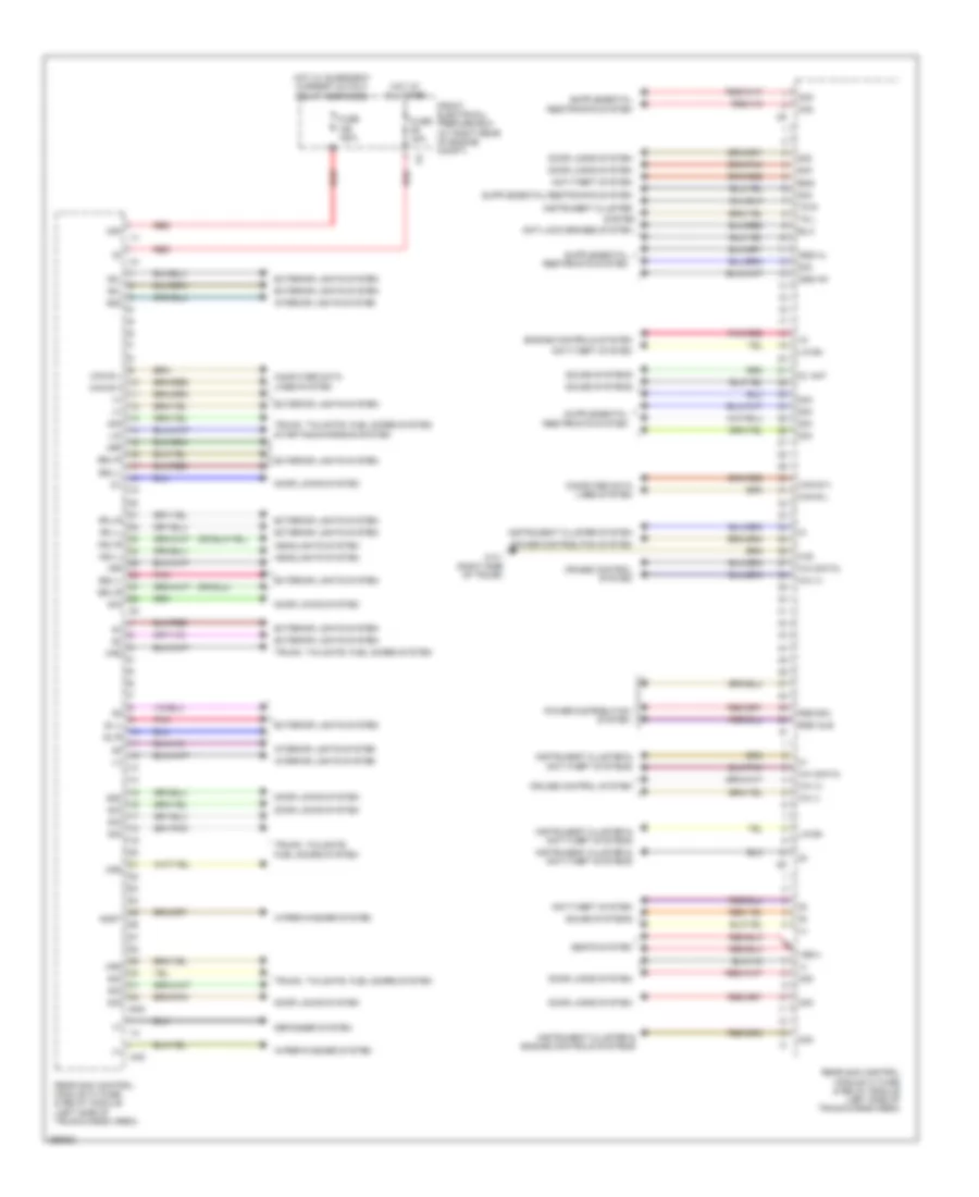
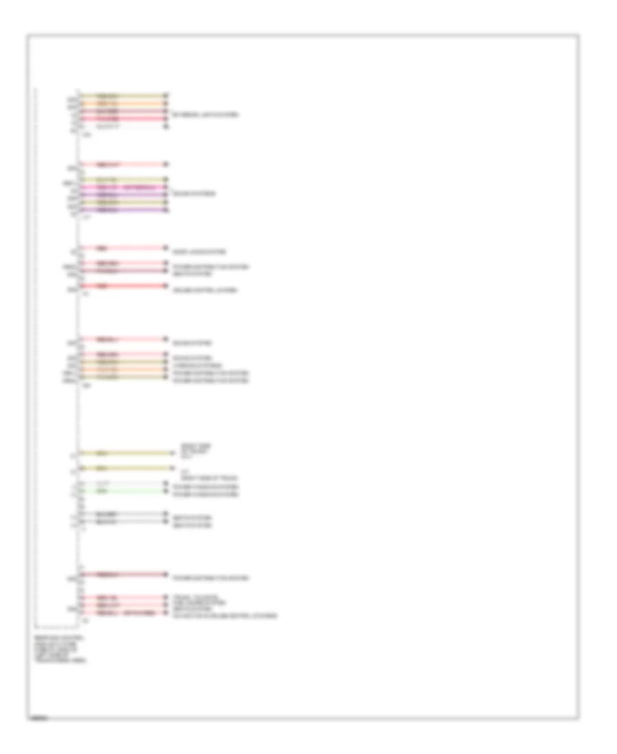
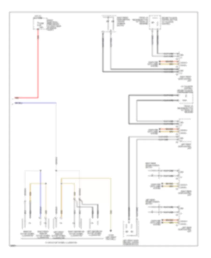
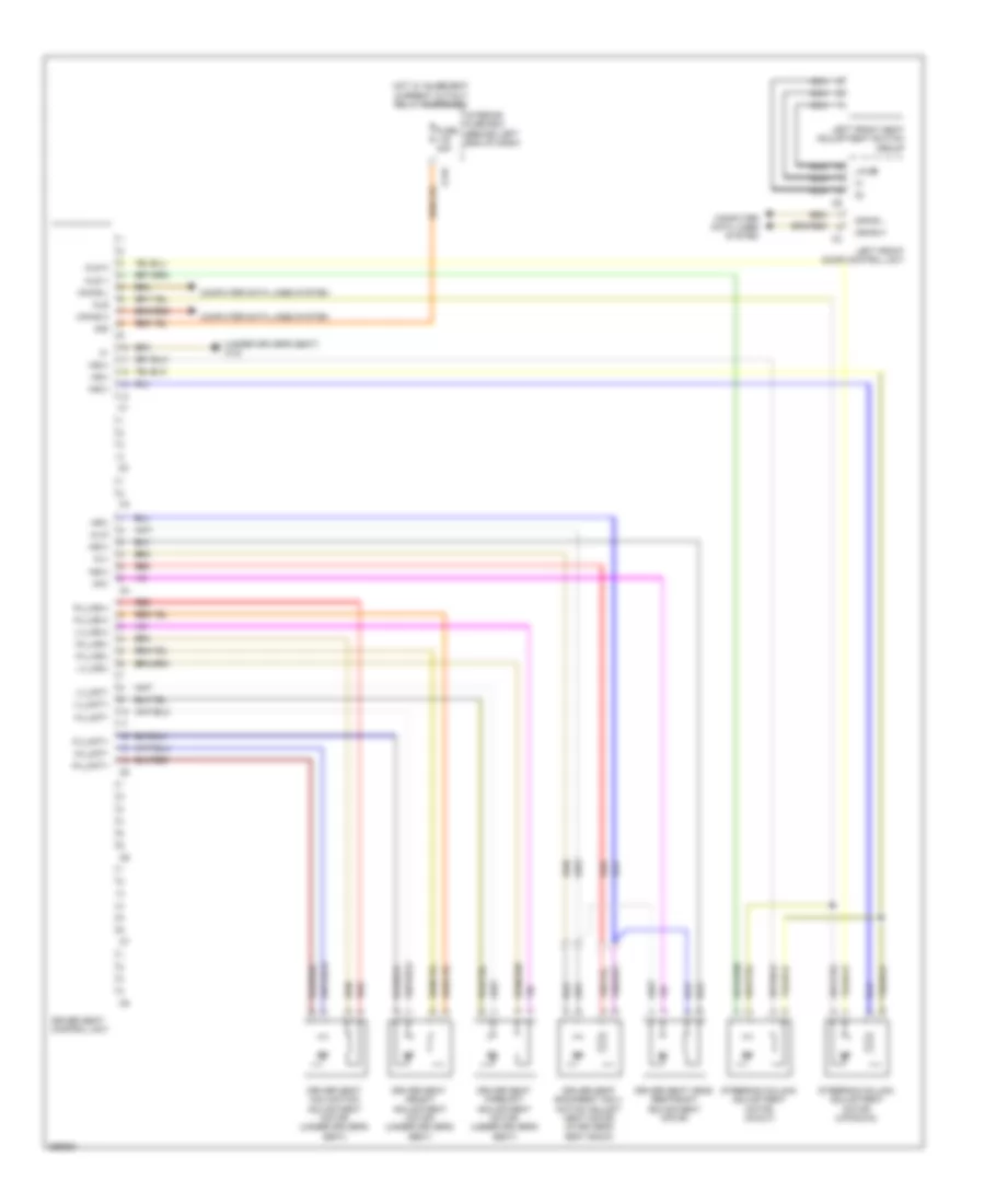
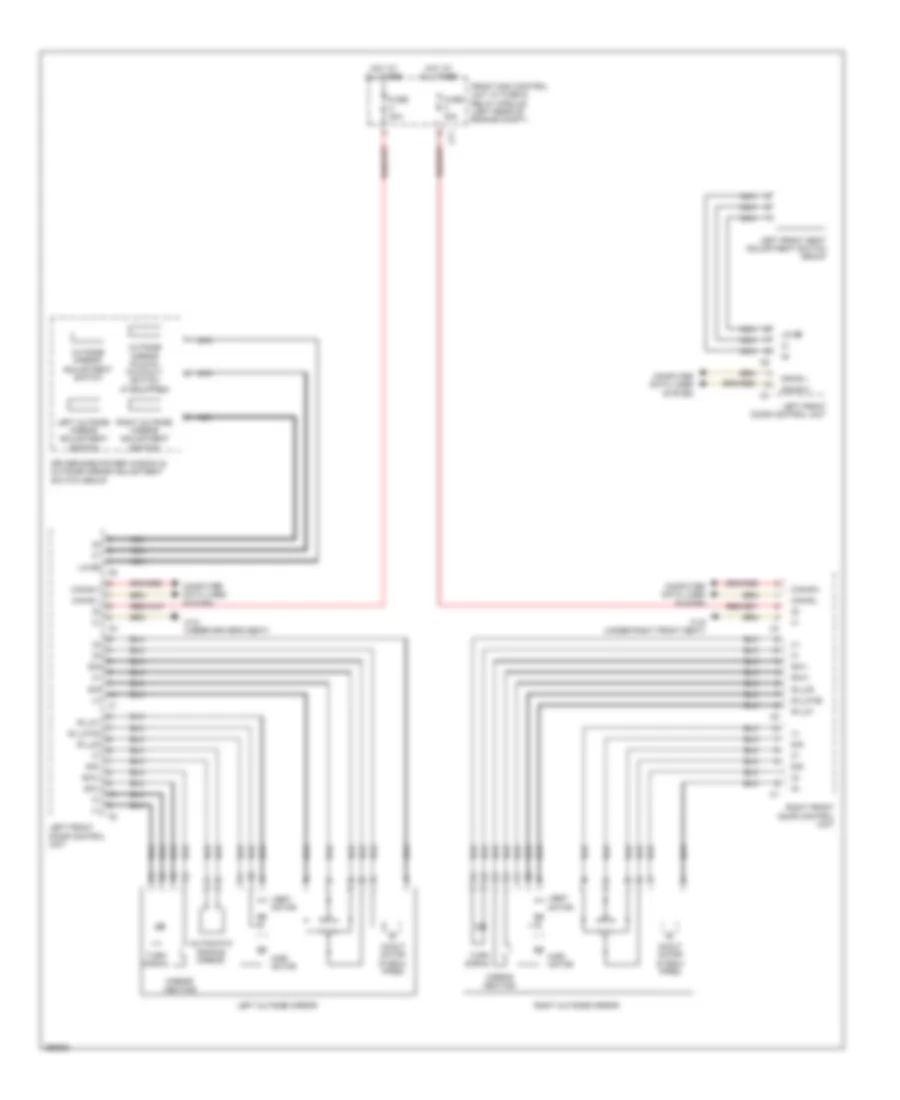
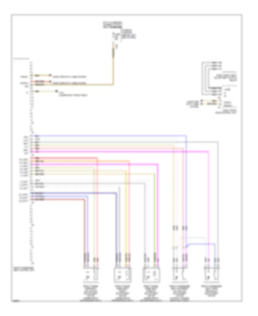
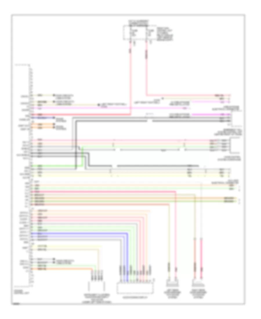
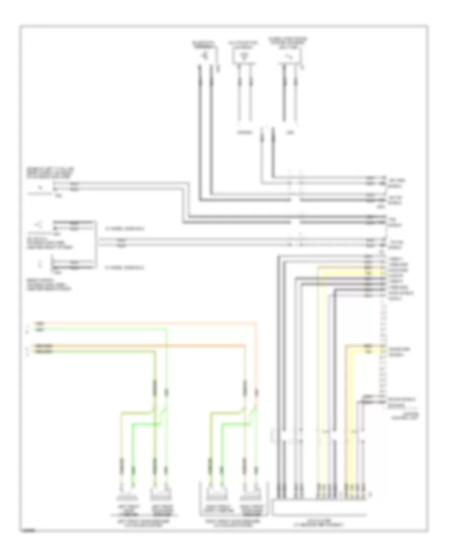
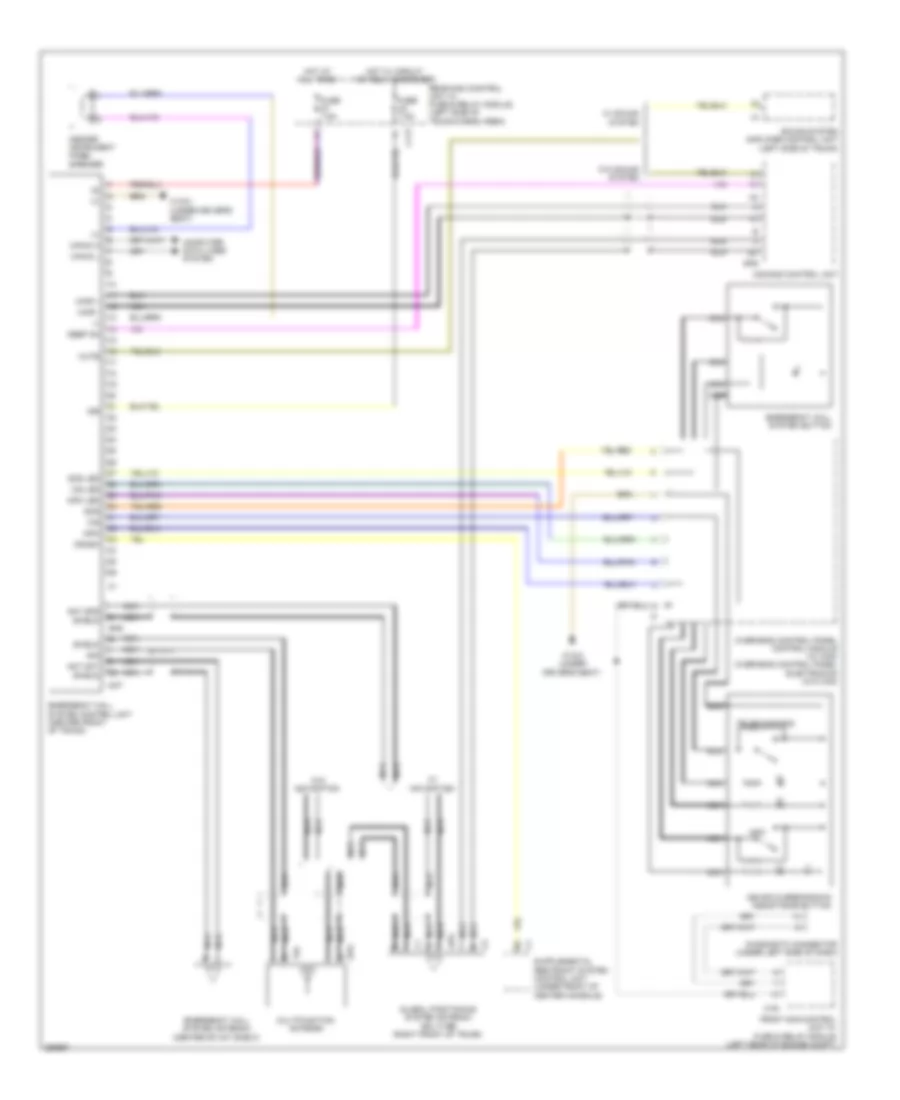
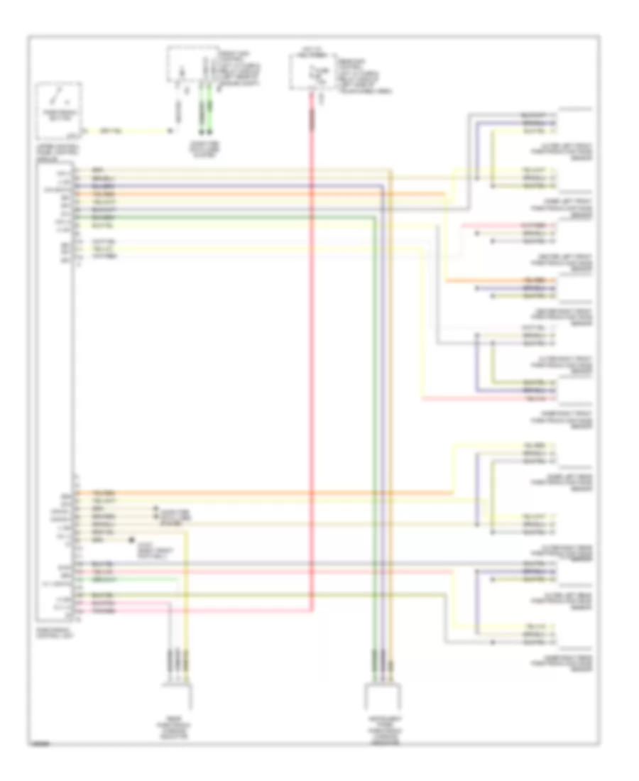
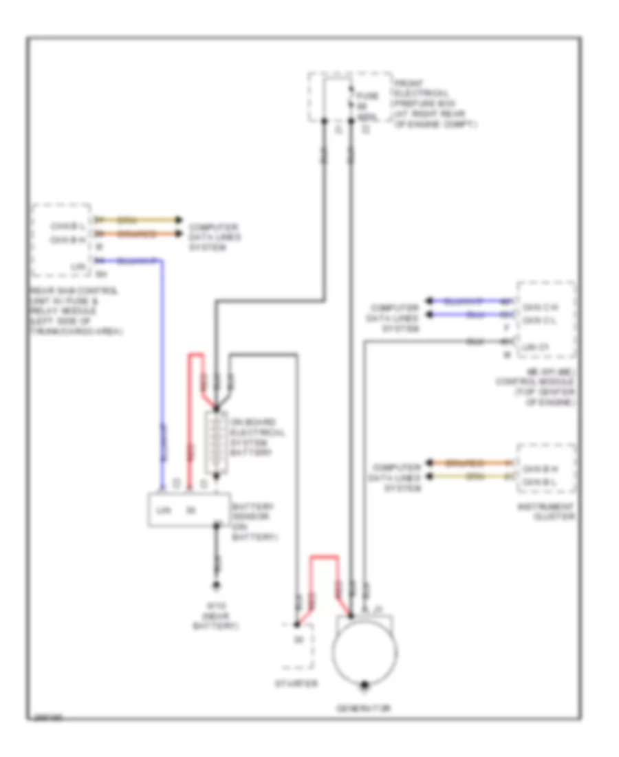
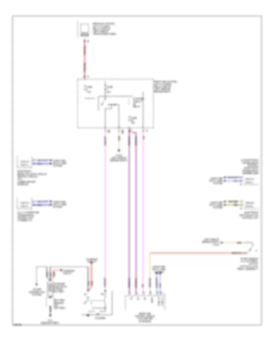
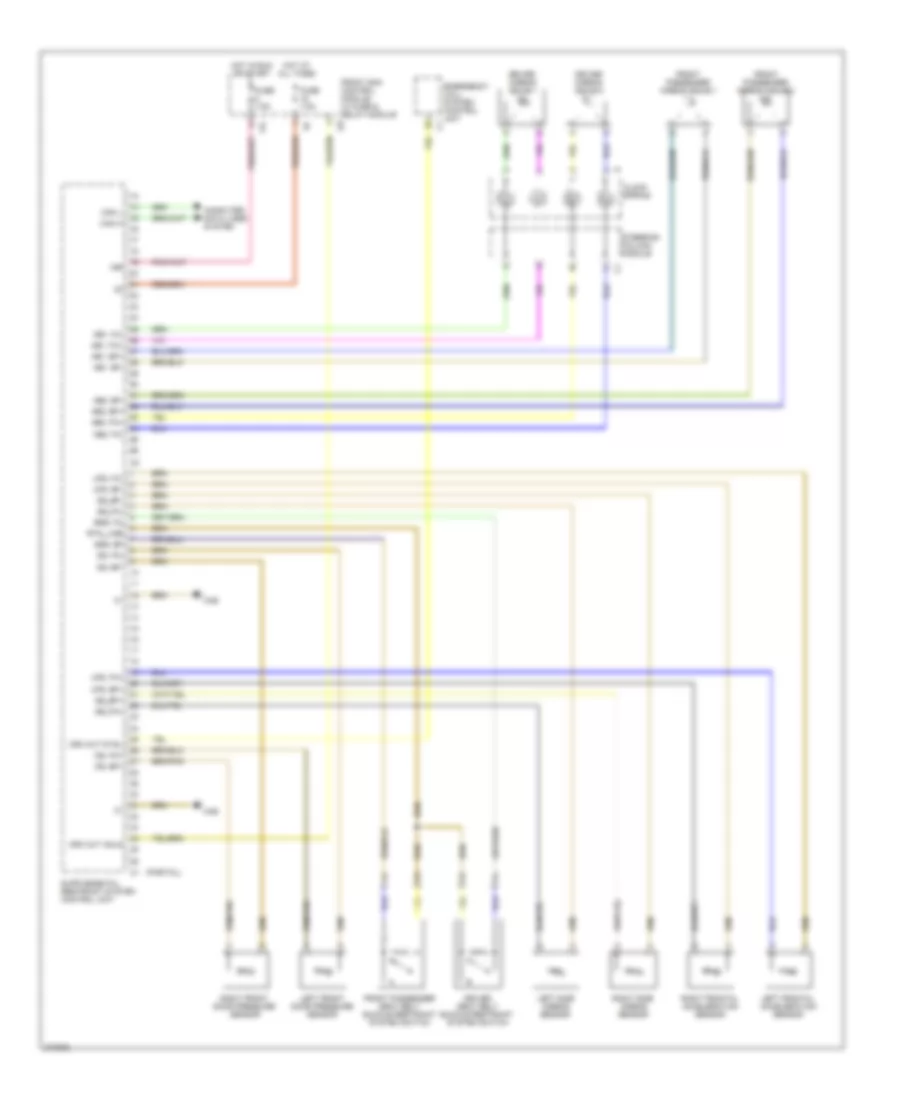
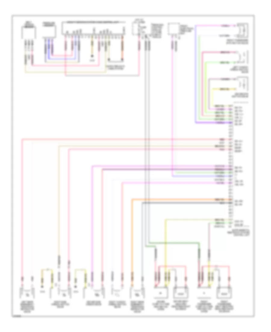
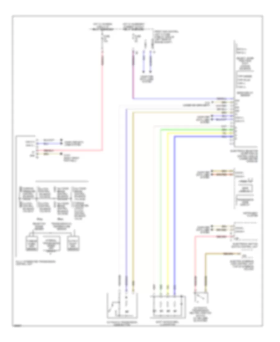
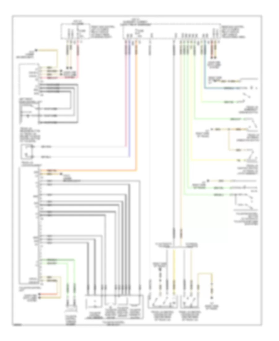
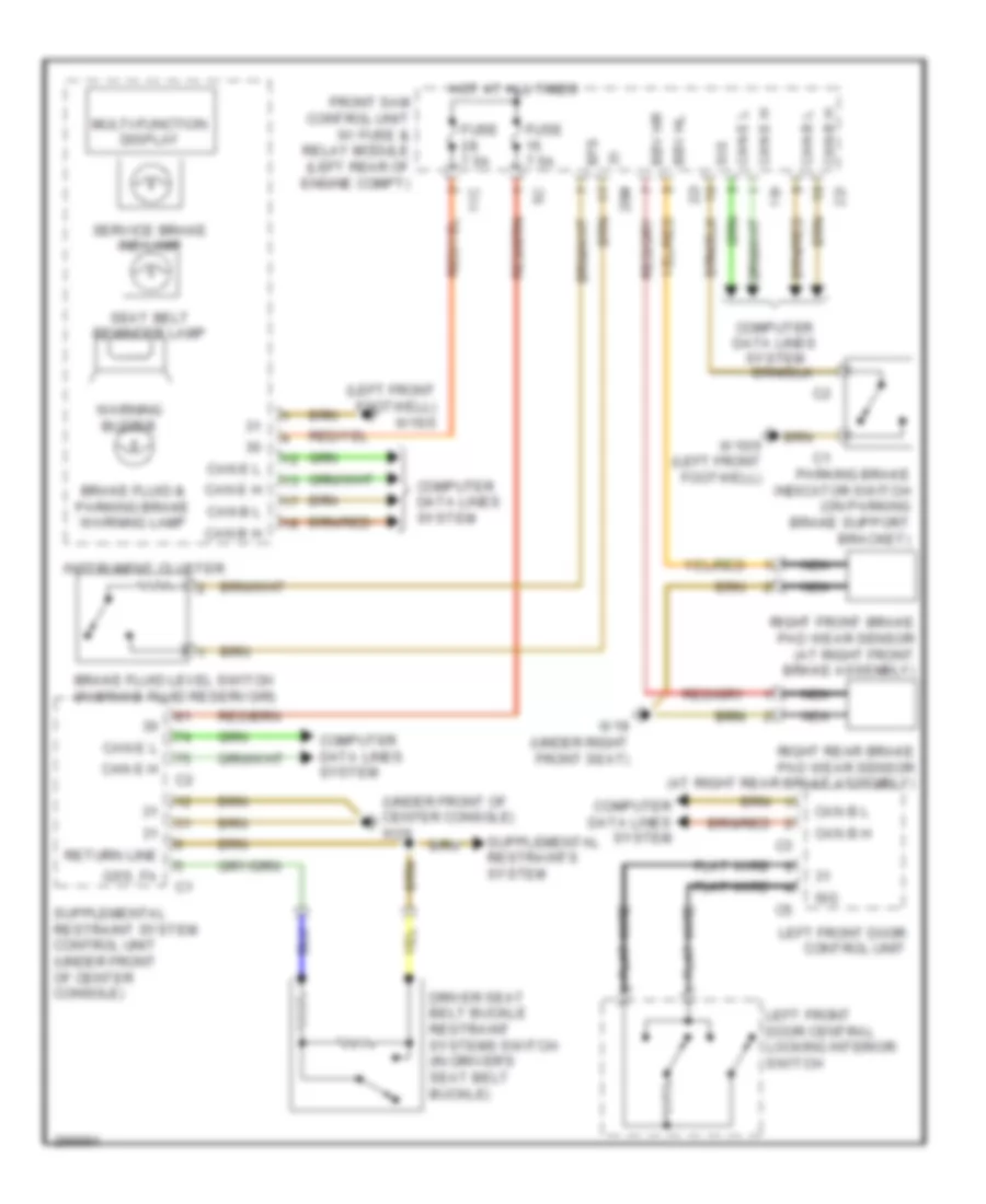
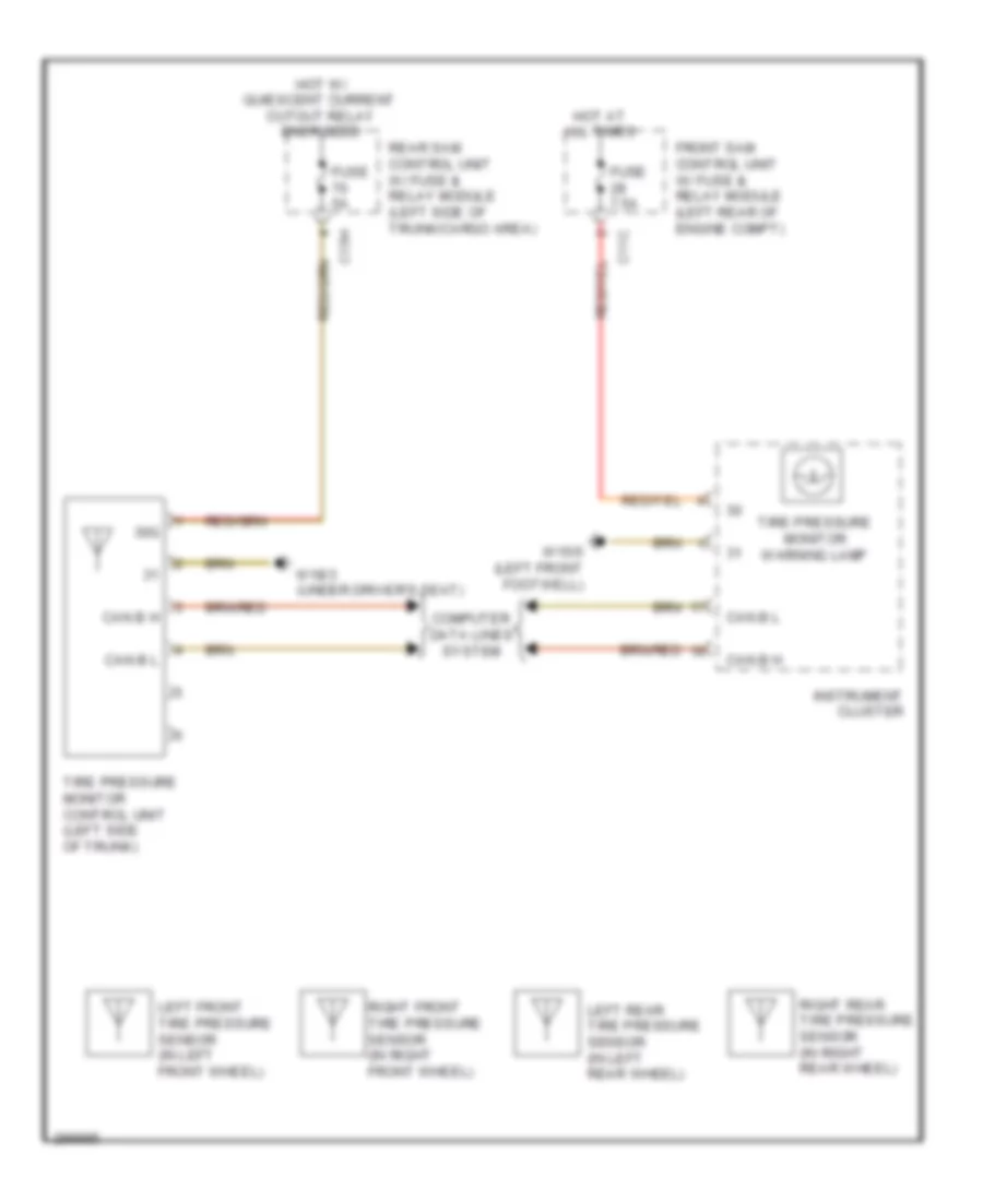
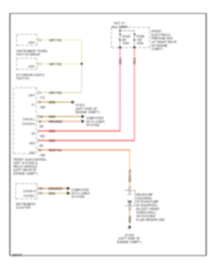
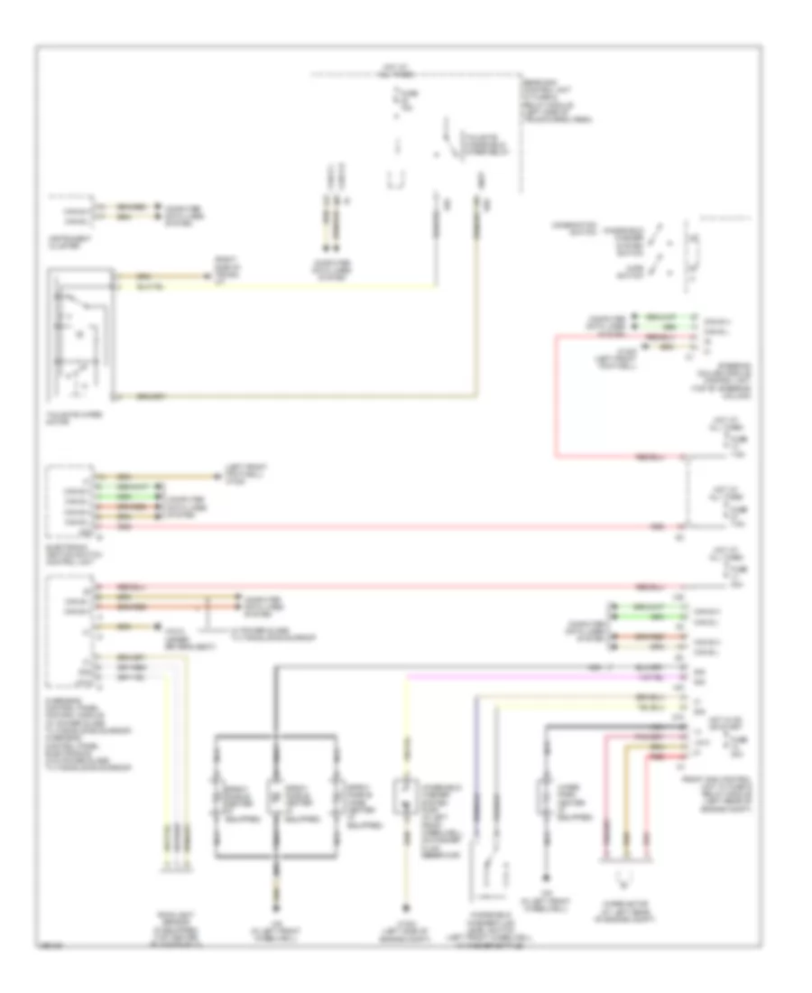
Diagram sections — 33 (88 total)
AIR CONDITIONING ANTI-LOCK BRAKES ANTI-THEFT BODY CONTROL MODULES COMPUTER DATA LINES COOLING FAN CRUISE CONTROL DEFOGGERS ELECTRONIC POWER STEERING ELECTRONIC SUSPENSION ENGINE PERFORMANCE EXTERIOR LIGHTS GROUND DISTRIBUTION HEADLIGHTS HORN INSTRUMENT CLUSTER INTERIOR LIGHTS MEMORY SYSTEMS NAVIGATION POWER DISTRIBUTION POWER DOOR LOCKS POWER MIRRORS POWER SEATS POWER TOP/SUNROOF POWER WINDOWS RADIO SHIFT INTERLOCK STARTING/CHARGING SUPPLEMENTAL RESTRAINTS TRANSMISSION TRUNK, TAILGATE, FUEL DOOR WARNING SYSTEMS WIPER/WASHER
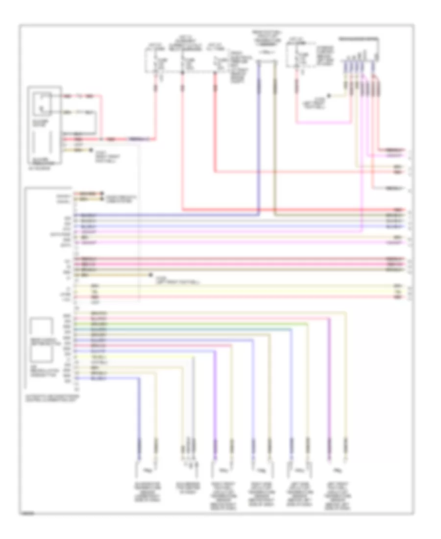
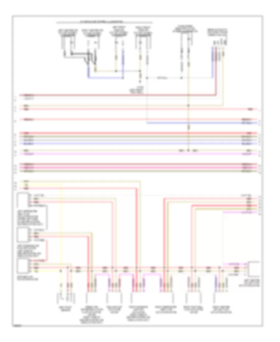
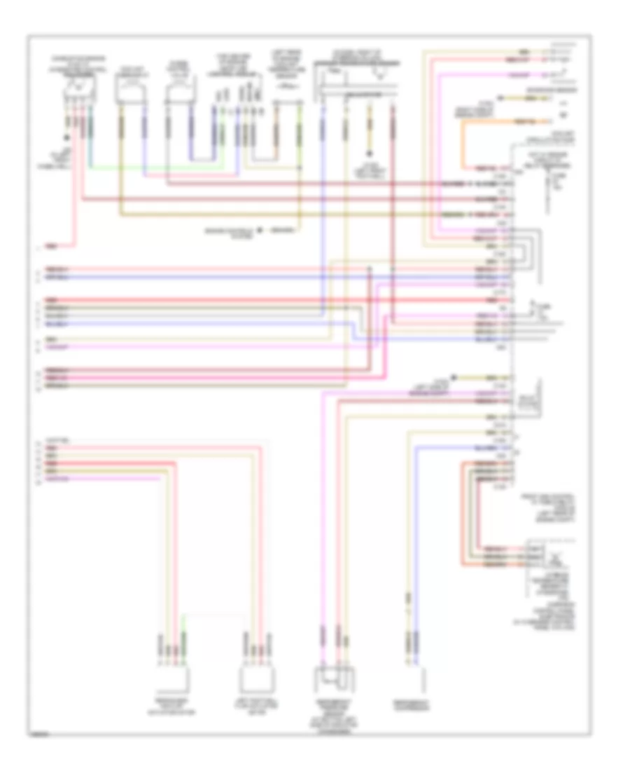
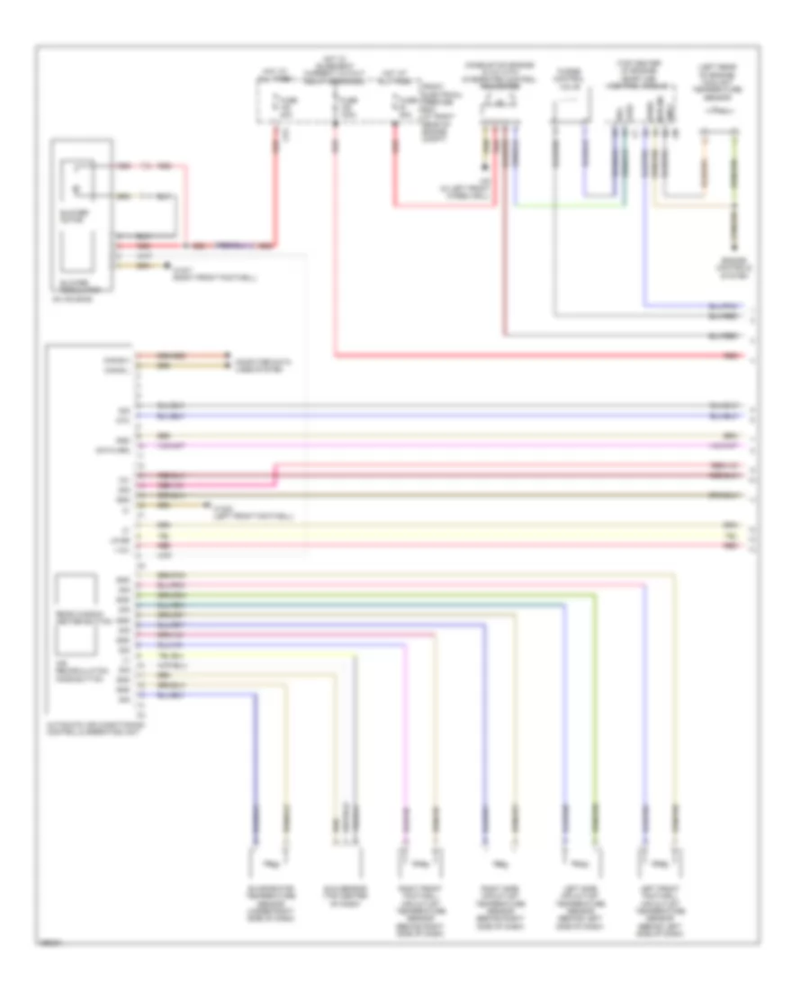
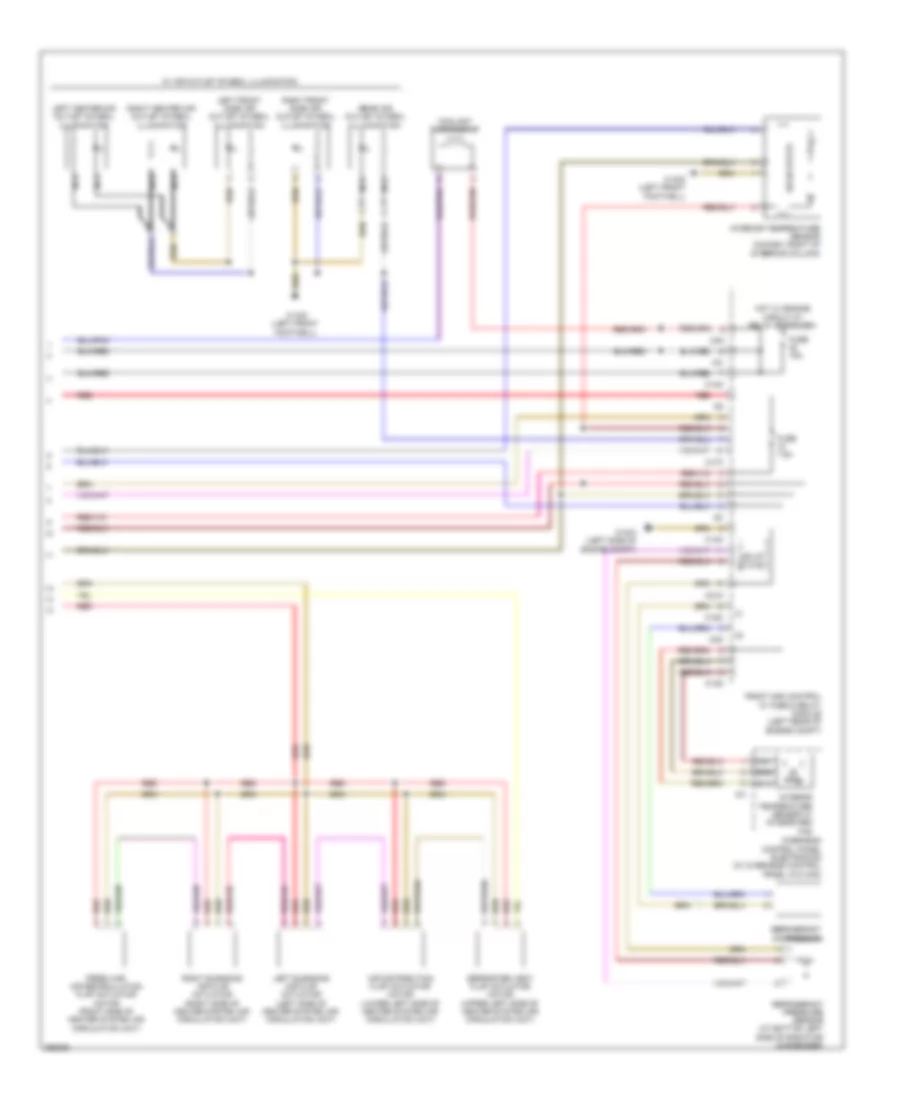
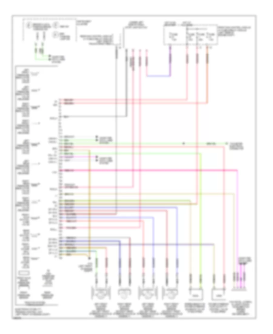
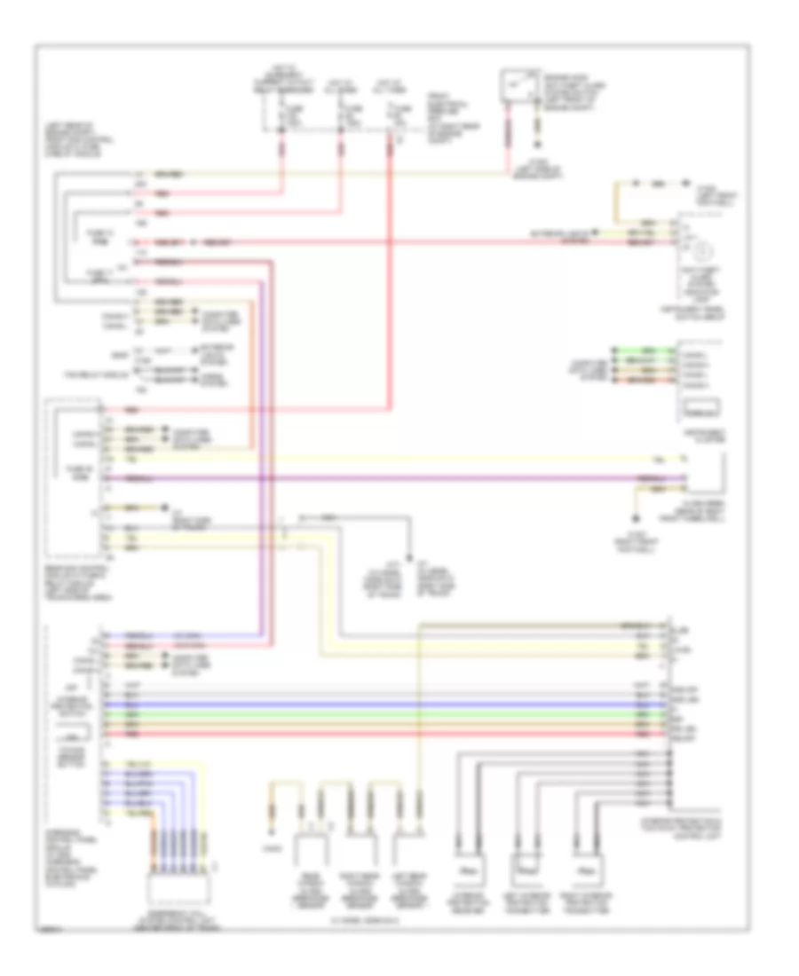
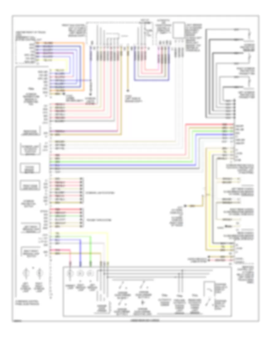
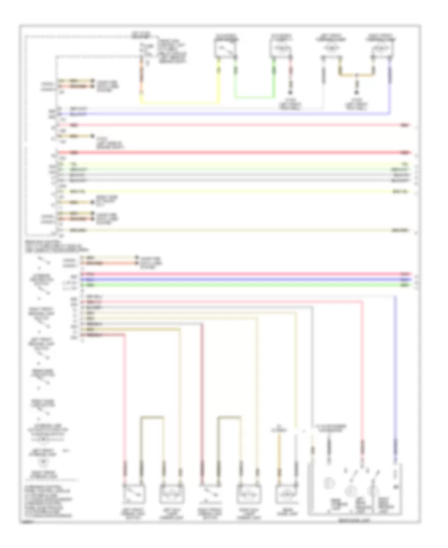
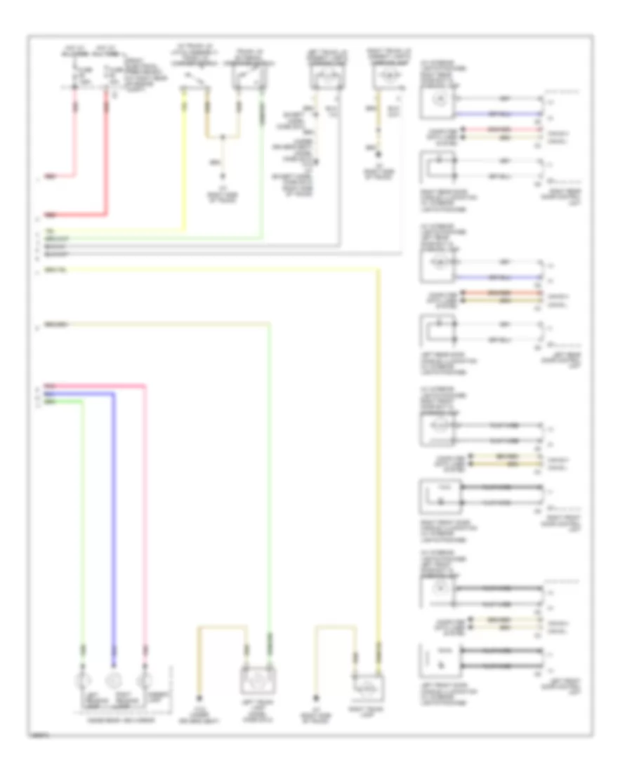
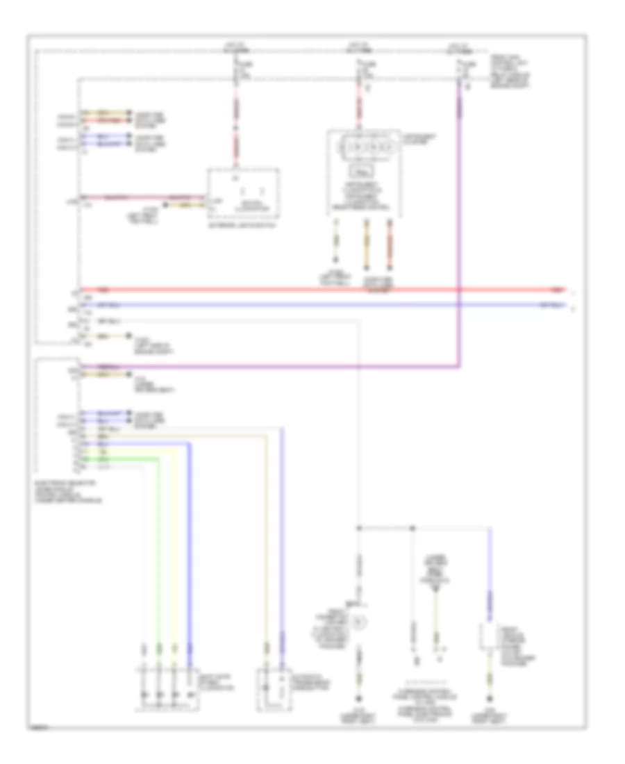
AIR CONDITIONING Automatic A/C Wiring Diagram, with Thermotronic (1 of 3) for Mercedes-Benz C300 4Matic 2008 List of elements for Automatic A/C Wiring Diagram, with Thermotronic (1 of 3) for Mercedes-Benz C300 4Matic 2008: 39 (+) (-) +12v 12v Ac housing Air recirculation mode button Automatic air conditioning control & operating unit Blower motor Blower regulator Can b h Can b l Computer data lines system Cp2 Data Data fond Evaporator temperature sensor (under right side of dash) Front electrical prefuse box (at right rear of engine compt) Fuse 100a Fuse 40a Fuse 7.5a Fuse 80a Gnd Hot at all times Hot w/ quiescent current cutout relay energized Interior fuse box (behind left end of dash) Left front footwell air outlet temperature sensor (behind left side of dash) Left side air outlet temperature sensor (behind left side of dash) Lin b8 Ntc Rear blower motor Rear footwell air outlet temperature sensor Rear window heater button Red Right front footwell air outlet temperature sensor (behind right side of dash) Right side air outlet temperature sensor (behind right side of dash) Sig Sun sensor (top center of dash) W15/5 (left front footwell) W15/7 (right front footwell) Automatic A/C Wiring Diagram, with Thermotronic (2 of 3) for Mercedes-Benz C300 4Matic 2008 List of elements for Automatic A/C Wiring Diagram, with Thermotronic (2 of 3) for Mercedes-Benz C300 4Matic 2008: 25 (if equipped) rear air outlet symbol illumination 12v 58d Data Dew point sensor Diffuse flap actuator motor Fresh air/ air recirculation flap actuator motor (right side of heater system air circulation unit) Gnd Left blending air flap actuator (left side of heater system air circulation unit) Left center air outlet symbol illumination Left center outlet flap actuator motor Left defroster vent flap actuator motor (upper left side of heater system air circulation unit) Left front side air outlet symbol illumination Nca Ram air flap actuator motor Rear automatic air conditioning operating unit Red Right blending air flap actuator (right side of heater system air circulation unit) Right center air outlet symbol illumination Right center outlet flap actuator motor Right defroster vent flap actuator motor Right footwell flap actuator motor Right front side air outlet symbol illumination W/ air outlet symbol illumination W15/5 (left front footwell) Automatic A/C Wiring Diagram, with Thermotronic (3 of 3) for Mercedes-Benz C300 4Matic 2008 List of elements for Automatic A/C Wiring Diagram, with Thermotronic (3 of 3) for Mercedes-Benz C300 4Matic 2008: 42 (in dash, right of steering column) interior temperature sensor (left rear of engine) coolant temperature sensor (top center of engine) me-sfi (me) control module 12v C13d C14m C17c C18m C21m C3m C4i C5c Combustion engine & a/c w/ integrated control fan motor Coolant circulation pump Coolant thermostat Emissions sensor Engine controls system Front sam control w/ fuse & relay module (left rear of engine compt) Fuse 15a Fuse 7.5a Gnd Hot w/ engine circuit 87 relay energized Interior temperature sensor w/ integrated fan Kwhs Left footwell flap actuator motor Lues Ntc Nwg m2 Overhead control panel electronics (w/ overhead control panel w/o can) Purge control valve Rear blend air flap actuator motor Red Refrigerant compressor Refrigerant pressure sensor (at bottom left side of radiator condenser) Reg Sig Solid state Tmot W15/5 (left front footwell) W16/3 (left side of engine compt) W16/4 (right side of engine compt) W9 (in left front wheelwell) Automatic A/C Wiring Diagram, without Thermotronic (1 of 2) for Mercedes-Benz C300 4Matic 2008 List of elements for Automatic A/C Wiring Diagram, without Thermotronic (1 of 2) for Mercedes-Benz C300 4Matic 2008: 45 (+) (left rear of engine) coolant temperature sensor (top center of engine) me-sfi (me) control module +12v 12v 30g Ac housing Air recirculation mode button Automatic air conditioning control & operating unit Blower motor Blower regulator Can-b h Can-b l Combustion engine & a/c with integrated control fan motor Computer data lines system Cp2 Data mrm Engine controls system Evaporator temperature sensor (under right side of dash) Front electrical prefuse box (at right rear of engine compt) Fuse 100a Fuse 40a Fuse 80a Gnd Hot at all times Hot w/ quiescent current cutout relay energized Kwhs Left front footwell air outlet temperature sensor (behind left side of dash) Left side air outlet temperature sensor (behind left side of dash) Lin b8 Lues Ntc Nwg m2 Purge control valve Rear window heater button Red Reg Right front footwell air outlet temperature sensor (behind right side of dash) Right side air outlet temperature sensor (behind right side of dash) Sig Sun sensor (top center of dash) Tmot W15/5 (left front footwell) W15/7 (right front footwell) W9 (in left front wheelwell) Automatic A/C Wiring Diagram, without Thermotronic (2 of 2) for Mercedes-Benz C300 4Matic 2008 List of elements for Automatic A/C Wiring Diagram, without Thermotronic (2 of 2) for Mercedes-Benz C300 4Matic 2008: 36 12v Air distribution flap actuator motor (lower left side of heater system air circulation unit) C13d C14m C17c C18m C21m C3m C4i Coolant thermostat Defroster vent flap actuator motor (upper left side of heater system air circulation unit) Fresh air/ air recirculation flap actuator motor (right side of heater system air circulation unit) Front sam control w/ fuse & relay module (left rear of engine compt) Fuse 15a Fuse 7.5a Gnd Hot w/ engine circuit 87 relay energized Interior temperature sensor (in dash, right of steering column) Interior temperature sensor w/ integrated fan Left blending air flap actuator (left side of heater system air circulation unit) Left center air outlet symbol illumination Left front side air outlet symbol illumination Nca Ntc Overhead control panel electronics (w/ overhead control panel w/o can) Rear air outlet symbol illumination Red Refrigerant compressor Refrigerant pressure sensor (at bottom left side of radiator condenser) Right blending air flap actuator (right side of heater system air circulation unit) Right center air outlet symbol illumination Right front side air outlet symbol illumination Solid state W/ air outlet symbol illumination W15/5 (left front footwell) W16/3 (left side of engine compt)
ANTI-LOCK BRAKES Anti-lock Brakes Wiring Diagram for Mercedes-Benz C300 4Matic 2008 List of elements for Anti-lock Brakes Wiring Diagram for Mercedes-Benz C300 4Matic 2008: 66 (-) (under left side of dash) stop lamp switch +12v 30g Abs ind Bla Bls_h Bls_l Bls_m Brake fluid & parking brake warning ind Can e h Can e l Can h h Can h l Can-e h Can-e l Computer data lines system Df hl m Df hl s Df hr m Df hr s Df vl m Df vl s Df vr m Df vr s Eco Eco 12v Electronic stability program control unit (left front of engine compt) Esp warning lamp ind Front axle brake pressure sensor Front axle intake ball valve Front axle switch- over valve Front pressure sensor Front sam control module w/ fuse & relay module (left rear of engine compt) Fuse 25a Fuse 40a Fuse 7.5a High pressure & return pump motor Hot at all times Hot in on or start Instrument cluster Left front axle rpm sensor (on left front steering knuckle assembly) Left front pressure regulator valve (hold) Left front pressure regulator valve (release) Left rear axle rpm sensor (on left rear steering knuckle assembly) Left rear pressure regulator valve (hold) Left rear pressure regulator valve (release) Nca Pml Pml 12v Power steering pump quantity control valve (if equipped) Rear axle intake ball valve Rear axle switch- over valve Rear pressure sensor Rear sam control module w/ fuse & relay module (left side of trunk/cargo area) Right front axle rpm sensor (on right front steering knuckle assembly) Right front pressure regulator valve (hold) Right front pressure regulator valve (release) Right rear axle rpm sensor (on right rear steering knuckle assembly) Right rear pressure regulator valve (hold) Right rear pressure regulator valve (release) Speed-sensitive power steering solenoid valve (if equipped) Taximeter electrical connector Traction system hydraulic unit W70 (left front of engine compt) Yaw rate, lateral & longitudinal acceleration sensor (under driver's seat)
ANTI-THEFT Anti-theft Wiring Diagram for Mercedes-Benz C300 4Matic 2008 List of elements for Anti-theft Wiring Diagram for Mercedes-Benz C300 4Matic 2008: 66 (left rear of engine compt) front sam control module w/ fuse & relay module (w/ can) (w/o can) 11c 12v 13d 15m 16s 20m 22i 56ar 58d Alarm siren (rear of right front wheelwell) Anti-theft alarm system indicator lamp Ass led Ass off C15m Can-b h Can-b l Can-e h Can-e l Computer data lines system Display Emergency call system control unit (center front of trunk) Engine hood anti-theft alarm system switch (left front of engine compt) Exterior lights system Fan relay module Front electrical prefuse box (at right rear of engine compt) Fuse 100a Fuse 125a Fuse 17 30a Fuse 18 7.5a Fuse 40a Fuse 46 7.5a Horns system Hot at all times Hot w/ quiescent current cutout relay energized Instrument cluster Instrument panel switch group Interior protection & tow-away protection control unit Interior protection receiver Interior protection switch Irs led Irs-off Left interior protection transmitter Left rear window glass breakage sensor Lin 1 Lin b4 Nca Off Overhead control panel module (w/ can) overhead control panel electronics (w/o can) Rear sam control module w/ fuse & relay module (left side of trunk/cargo area) Rear window glass breakage sensor Red Right interior protection transmitter Right rear window glass breakage sensor S_gb Towing sensor button W/ model code 204.2 W15/5 (left front footwell) W15/7 (right front footwell) W16/3 (left side of engine compt) W48/2 W7 (right side of trunk) W7 (w/ model code 204.0) (right side of trunk) W7/1 (w/ model code 204.2) (right side of trunk)
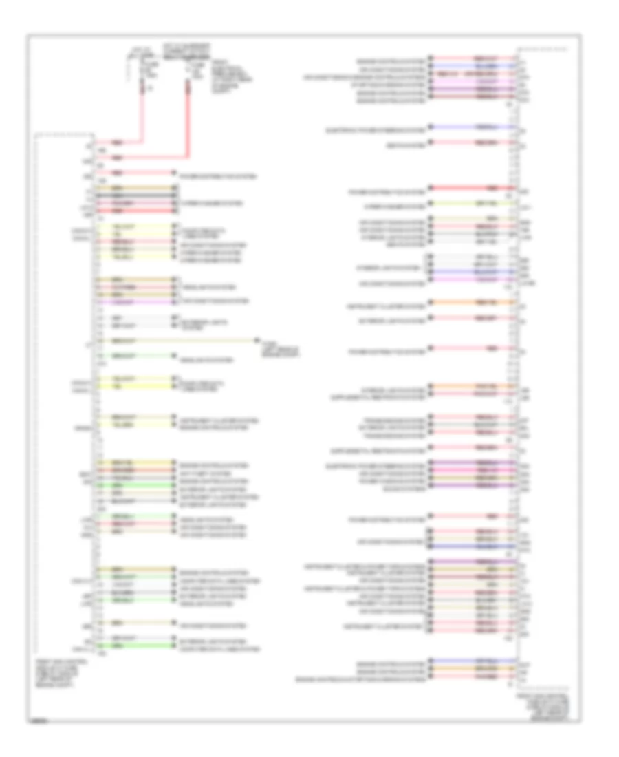
BODY CONTROL MODULES Front SAM Control Module Wiring Diagram (1 of 2) for Mercedes-Benz C300 4Matic 2008 List of elements for Front SAM Control Module Wiring Diagram (1 of 2) for Mercedes-Benz C300 4Matic 2008: 62 (+) 11c 12s 12v 13d 15r 16s 17c 18m 20m 21m 30g 30z 49p 55r 58d 87f 87m Air conditioning & engine controls systems Air conditioning system Anti-theft system Can c h Can c l Can-g h Can-g l Computer data lines system Crash Edw Electronic power steering system Engine controls & starting/charging systems Engine controls system Exterior lights system Front electrical prefuse box (at right rear of engine compt) Front sam control module w/ fuse & relay module (left rear of engine compt) Fuse 100a Fuse 125a Gnd Headlights system Hot at all times Hot w/ quiescent current cutout relay energized Instrument cluster & power tops systems Instrument cluster system Interior lights system Lin 1 Lin 2 Lin b8 Lwr Nca Ntc Pnk/red Power distribution system Power windows system Red Rfl Seats system Sig Slp Sound systems Starting/charging system Transmissions system W16/5 (left rear of engine compt) Wiper/washer system Front SAM Control Module Wiring Diagram (2 of 2) for Mercedes-Benz C300 4Matic 2008 List of elements for Front SAM Control Module Wiring Diagram (2 of 2) for Mercedes-Benz C300 4Matic 2008: 58 (+) 10t 14m 15m 15r 19i 22i 30g 31e 55l 55r 56al 56ar 56b l 56br 58d 58l 58r 87 rly Air conditioning & cooling fans systems Air conditioning system Anti-lock brakes system Anti-theft system Bbv hl Bbv hr Can b h Can b l Can c h Can c l Can d h Can d l Can e h Can e l Computer data lines system Computer data lines system sound systems Crash Door locks & mirror systems Door locks system Ekp Engine controls system Exterior lights & anti-lock brakes systems Exterior lights system Front sam control module w/ fuse & relay module (left rear of engine compt) Headlights & exterior lights systems Headlights system Horns system Instrument cluster system Interior lights system Pnk/red Power distribution system Red Sig Sound systems Starting/charging system Str W16/3 (left side of engine compt) W16/5 (left rear of engine compt) Wiper/washer system Rear SAM Control Module Wiring Diagram (1 of 2) for Mercedes-Benz C300 4Matic 2008 List of elements for Rear SAM Control Module Wiring Diagram (1 of 2) for Mercedes-Benz C300 4Matic 2008: 70 (+) 15r 15r(1) 30g 31e 49r 4hd 58d 58l 6hd Anst Anti-lock brakes system Anti-theft system Bla Bsl-l Bsl-r Can b h Can b l Computer data lines system Cruise control system Defogger system Door locks system Edm Engine controls system Exterior lights system Front electrical prefuse box (at right rear of engine compt) Fuel doors system Fuse 150a Fuse 40a Gss hl Gss hm Headlights system Hfe Hot at all times Hot w/ quiescent current cutout relay energized Instrument cluster Instrument cluster & anti-theft systems Instrument cluster & engine controls systems Instrument cluster system Interior lights system Lin Lin b4 Nsl-l Nsl-r Pnk Pnk/red Power distribution system Rear sam control module w/ fuse & relay module (left side of trunk/cargo area) Red Rfl-l Rfl-r Rss aus Rss ein Seats system Sig Sl-l Sl-r Sound systems Starting/charging system System Tg l Tg r Trunk, tailgate, Trunk, tailgate, fuel doors system W7/1 (right side of trunk) Wh (+) Wh (-) Wh (data) Wiper/washer system Zv ant Rear SAM Control Module Wiring Diagram (2 of 2) for Mercedes-Benz C300 4Matic 2008 List of elements for Rear SAM Control Module Wiring Diagram (2 of 2) for Mercedes-Benz C300 4Matic 2008: 27 (+) (-) (or pnk/red) (right side of trunk) w7/1 11t 12i 13a 14i 15h 15r(1) 15r(2) 30g Cruise control system Door locks system Exterior lights system Navigation & cruise control systems Pnk/red Power distribution system Power windows system Rear sam control module w/ fuse & relay module (left side of trunk/cargo area) Red Seats system Sound system Sound systems Trunk, tailgate, fuel doors system seats system W7 (right side of trunk) Warning systems
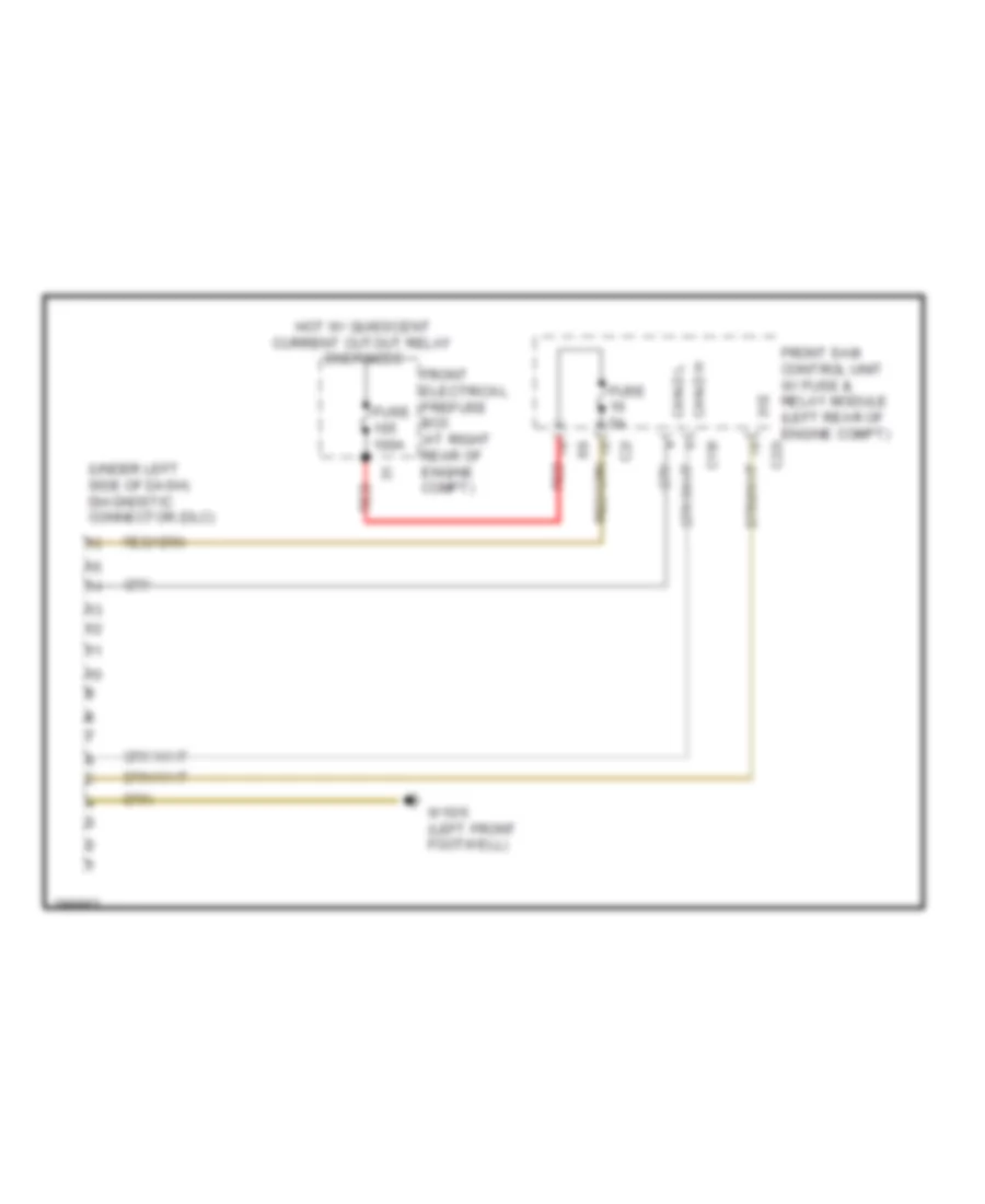
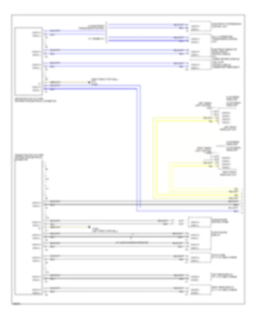
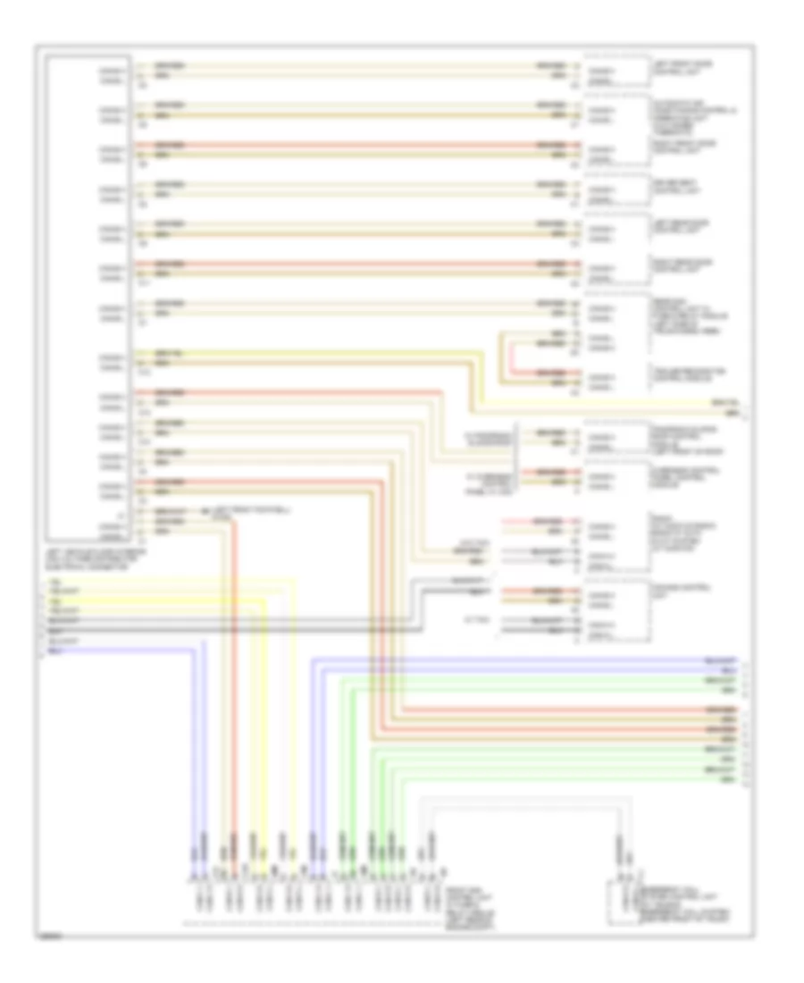
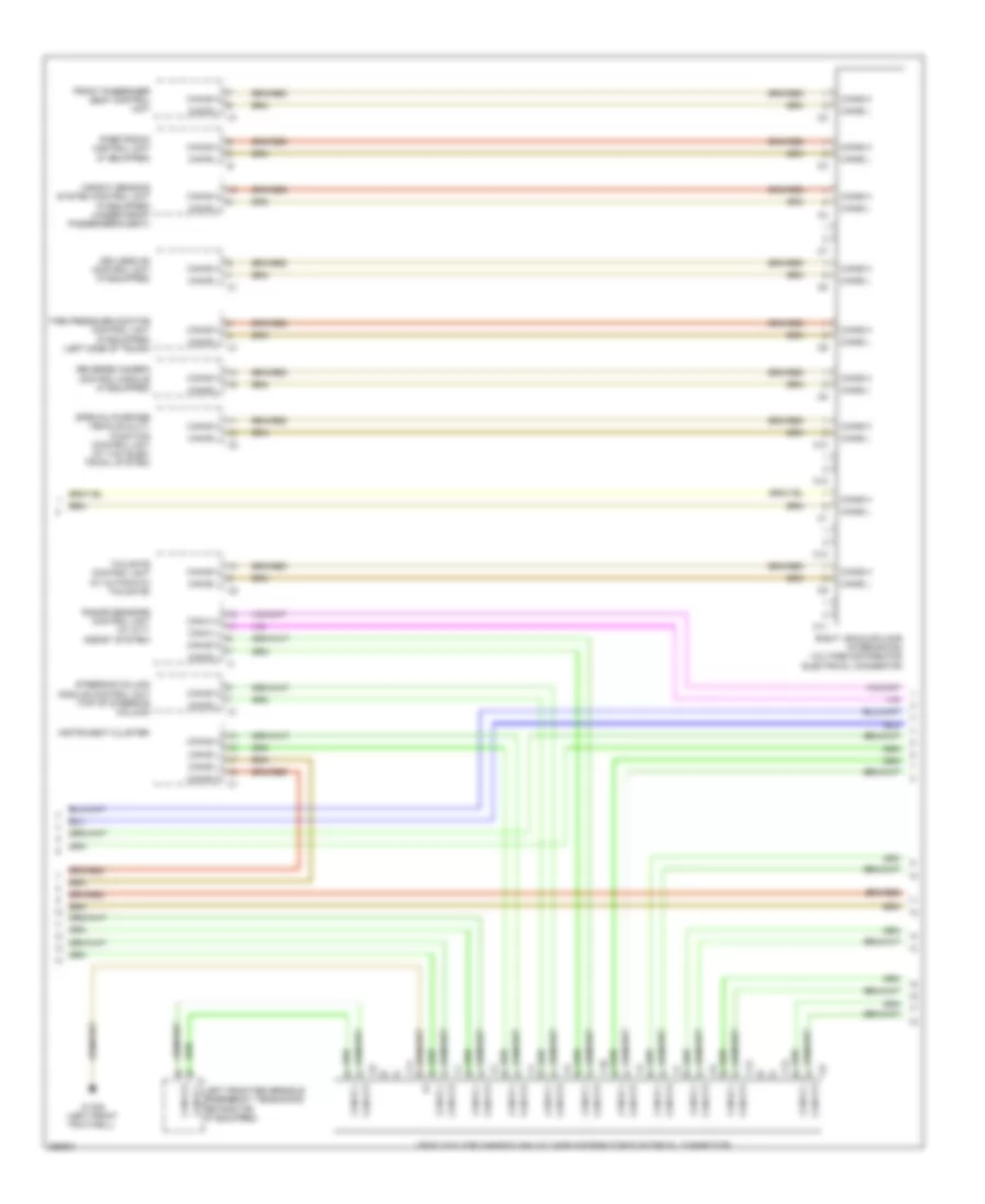
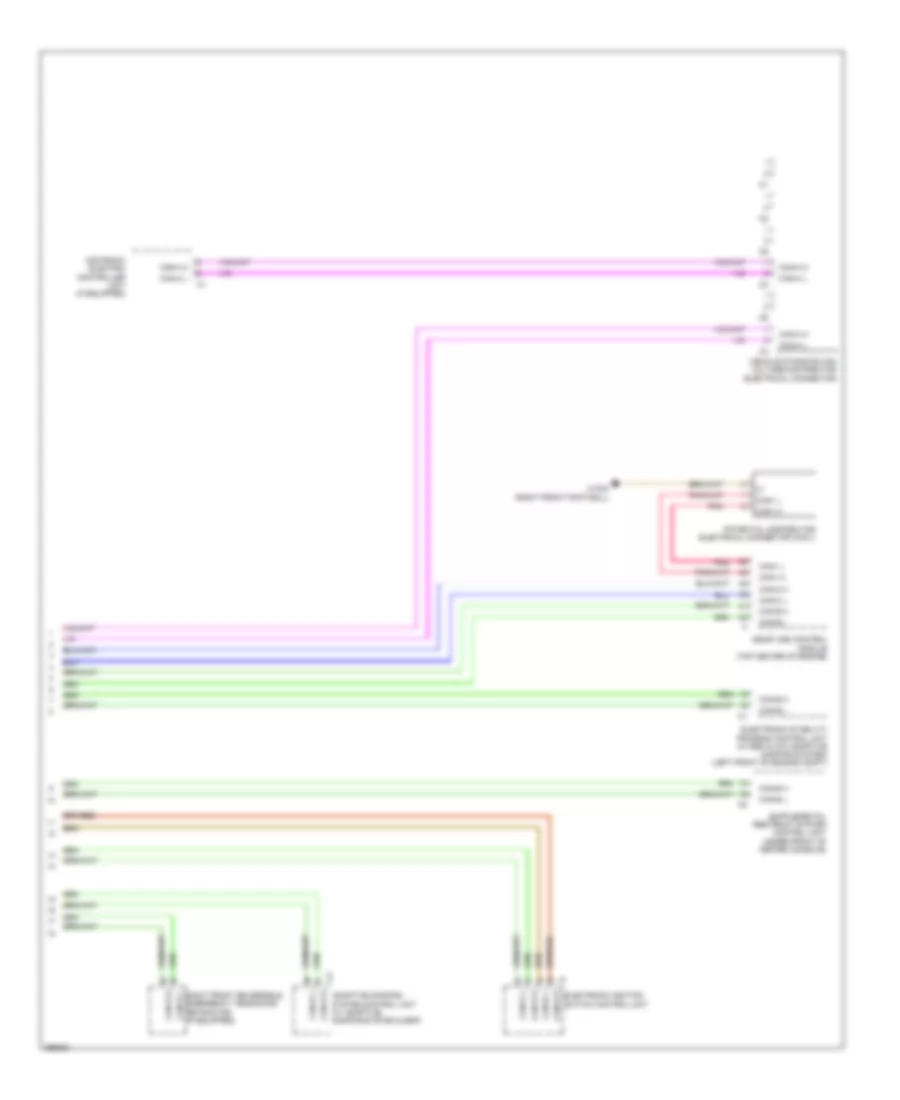
COMPUTER DATA LINES Data Link Connector Wiring Diagram for Mercedes-Benz C300 4Matic 2008 List of elements for Data Link Connector Wiring Diagram for Mercedes-Benz C300 4Matic 2008: 14 (under left side of dash) diagnostic connector (dlc) 31e C19i C22i C2i Can-d h Can-d l Front electrical prefuse box (at right rear of engine compt) Front sam control unit w/ fuse & relay module (left rear of engine compt) Fuse 100a Fuse 5a Hot w/ quiescent current cutout relay energized Red W15/5 (left front footwell) High/Low Bus Wiring Diagram (1 of 4) for Mercedes-Benz C300 4Matic 2008 List of elements for High/Low Bus Wiring Diagram (1 of 4) for Mercedes-Benz C300 4Matic 2008: 34 (right front footwell) (m/t) w15/8 (w/ audio 20 radio & radio 50) Audio/comand control panel Audio/comand display C10 C11 C12 C13 Can-a h Can-a l Can-b h Can-b l Can-c h Can-c l Can-g h Can-g l Drivetrain can voltage distributor electrical connector Dvd player (w/ tv & video in rear) Electronic selector level module control module (a/t) (under center console) Electronic transmission control unit Fuel pump control module (under right rear seat) Fully integrated transmission control unit Left front headlamp unit Left rear display (w/ tv & video in rear) Left xenon light control unit Right front headlamp unit Right rear display (w/ tv & video in rear) Right xenon light control unit Telematics can voltage distributor electrical connector W/ 7-speed a/t W/ bi-xenon headlamp W/ electronic transmission control W/o bi-xenon headlamp W15/6 (left front footwell) High/Low Bus Wiring Diagram (2 of 4) for Mercedes-Benz C300 4Matic 2008 List of elements for High/Low Bus Wiring Diagram (2 of 4) for Mercedes-Benz C300 4Matic 2008: 43 (left front footwell) w15/6 10i 18m 19i 20m 21m Automatic air conditioning control & operating unit (2 & 3 zones thermatic) C10 C11 C12 C13 C22i C2i Can-a h Can-a l Can-b h Can-b l Can-c h Can-c l Can-d h Can-d l Can-e h Can-e l Can-g h Can-g l Comand control unit Driver seat control unit Emergency call system control unit (w/ teleaid emergency call system) (center front of trunk) Front sam control unit w/ fuse & relay module (left rear of engine compt) Left front door control unit Left rear door control unit Left vehicle floor interior can voltage distributor electrical connector Overhead control panel control module Panoramic sliding roof control module (left front of roof) Radio (w/ audio 20 radio) radio w/ auto pilot system (w/ audio 50) Rear sam control unit w/ fuse & relay module (left side of trunk/cargo area) Right front door control unit Right rear door control unit Trailer recognition control module W/ overhead control panel w/ can W/ panoramic sliding roof W/ taxi W/o taxi High/Low Bus Wiring Diagram (3 of 4) for Mercedes-Benz C300 4Matic 2008 List of elements for High/Low Bus Wiring Diagram (3 of 4) for Mercedes-Benz C300 4Matic 2008: 25 C10 C11 C12 C13 Can-b h Can-b l Can-e h Can-e l Can-h h Can-h l Front passenger seat control unit Instrument cluster Keyless go control unit (if equipped) Left front reversible emergency tensioning retractor (if equipped) Parktronic control unit (if equipped) Radar sensors control unit (w/ city assist system) Reverse camera control module (if equipped) Right vehicle floor interior can voltage distributor electrical connector Special-purpose vehicle multi- function control unit (w/ taxi elec- trical system) Steering column module control unit (top of steering column) Tailgate control unit (w/ automatic tailgate) Tire pressure monitor control unit (if equipped) (left side of trunk) Vehicle floor chassis can voltage distributor electrical connector W15/6 (left front footwell) Weight sensing system control unit (if equipped) (under front passenger's seat) High/Low Bus Wiring Diagram (4 of 4) for Mercedes-Benz C300 4Matic 2008 List of elements for High/Low Bus Wiring Diagram (4 of 4) for Mercedes-Benz C300 4Matic 2008: 20 Adaptive damping system control unit (w/ adaptive damping system & esp) Can-b h Can-b l Can-c h Can-c l Can-e h Can-e l Can-h h Can-h l Can-i h Can-i l Distronic electric controller unit (if equipped) Electronic ignition switch control unit Electronic stability program control unit (w/ esp & w/o adaptive damping system) (left front of engine compt) Me-sfi (me) control module (top center of engine) Pnk Potential distributor electrical connector (can i) Right front reversible emergency tensioning retractor (if equipped) Vehicle dynamics can voltage distributor electrical connector W15/8 (right front footwell)
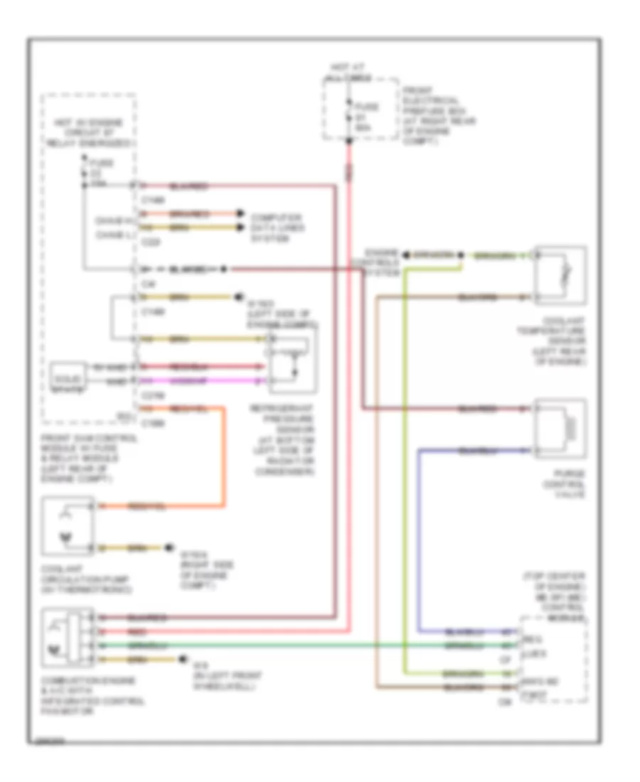
COOLING FAN Cooling Fan Wiring Diagram for Mercedes-Benz C300 4Matic 2008 List of elements for Cooling Fan Wiring Diagram for Mercedes-Benz C300 4Matic 2008: 33 (top center of engine) me-sfi (me) control module 5v khd C14m C18m C21m C22i C4i Can-b h Can-b l Combustion engine & a/c with integrated control fan motor Computer data lines system Coolant circulation pump (w/ thermotronic) Coolant temperature sensor (left rear of engine) Engine controls system Front electrical prefuse box (at right rear of engine compt) Front sam control module w/ fuse & relay module (left rear of engine compt) Fuse 15a Fuse 80a Hot at all times Hot w/ engine circuit 87 relay energized Khd Lues Nwg m2 Purge control valve Red Refrigerant pressure sensor (at bottom left side of radiator condenser) Reg Sig Solid state Tmot W16/3 (left side of engine compt) W16/4 (right side of engine compt) W9 (in left front wheelwell)
CRUISE CONTROL Cruise Control Wiring Diagram for Mercedes-Benz C300 4Matic 2008 List of elements for Cruise Control Wiring Diagram for Mercedes-Benz C300 4Matic 2008: 78 (+) sv (blind spot assist) (distronic plus) (right front footwell) w15/7 (right side of trunk) w7/1 12i 14i Acc Accel/ set Accelerator pedal sensor (top of accelerator pedal assembly) C2i Can c h Can c l Can e h Can e l Can h h Can h l Can-c h Can-c l Computer data lines system Cruise control lever Data Dcm Dcp Dec Decel/ set Diode (usa) Distronic control (if equipped) Distronic control unit Distronic electric controller unit Distronic radar sensor Front bumper left inner radar sensor Front bumper left outer radar sensor Front bumper right inner radar sensor Front bumper right outer radar sensor Front sam control unit w/ fuse & relay module (left rear of engine compt) Fully integrated transmission control unit Fuse 7.5a Hot at all times Hot in on or start Hot w/ chassis circuit 87 relay energized Ind Instrument panel parktronic warning indicator Ip1s Ip2s Ipm Light emitting speedtronic Me-sfi control module (top center of engine) Nca Off Output shaft rpm sensor Pnk/red Radar sensors control unit Rear bumper left inner radar sensor Rear bumper left outer radar sensor Rear bumper right inner radar sensor Rear bumper right outer radar sensor Rear parktronic warning indicator Rear sam control unit w/ fuse & relay module (left side of trunk/ cargo area) Red Res Resume Sh_high Sh_low Sp1m Sp1s Sp2m Sp2s Speed Speedtronic Steering column module control unit (top of steering column) Sv_high Sv_low Throttle valve actuator (part of throttle valve actuator) U_pwg1 W15/5 (left front footwell) W15/7 (right front footwell) W18 (under driver's seat)
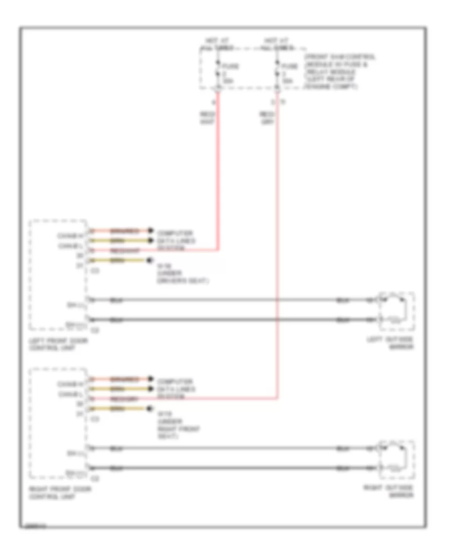
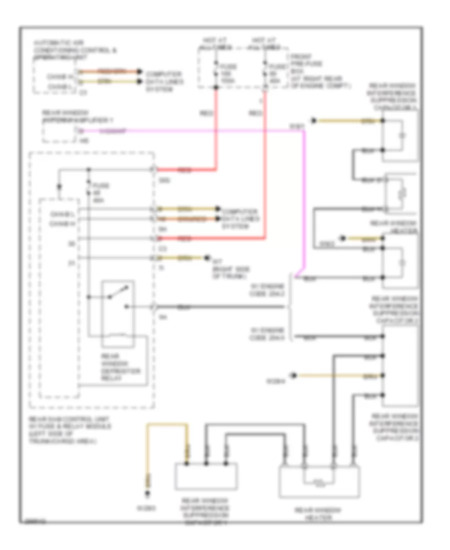
DEFOGGERS Heated Mirrors Wiring Diagram for Mercedes-Benz C300 4Matic 2008 List of elements for Heated Mirrors Wiring Diagram for Mercedes-Benz C300 4Matic 2008: 14 Can-b h Can-b l Computer data lines system Front sam control module w/ fuse & relay module (left rear of engine compt) Fuse 30a Hot at all times Left front door control unit Left outside mirror Right front door control unit Right outside mirror Sh (+) Sh (-) W18 (under driver's seat) W19 (under right front seat) Rear Defogger Wiring Diagram for Mercedes-Benz C300 4Matic 2008 List of elements for Rear Defogger Wiring Diagram for Mercedes-Benz C300 4Matic 2008: 23 30g Automatic air conditioning control & operating unit Can-b h Can-b l Computer data lines system Front pre-fuse box (at right rear of engine compt) Fuse 150a Fuse 40a Hot at all times Rear sam control unit w/ fuse & relay module (left side of trunk/cargo area) Rear window antenna amplifier 1 Rear window defroster relay Rear window heater Rear window interference suppression capacitor 1 Rear window interference suppression capacitor 2 Red W/ engine code 204.0 W/ engine code 204.2 W29/3 W29/4 W7 (right side of trunk) W8/1 W8/2
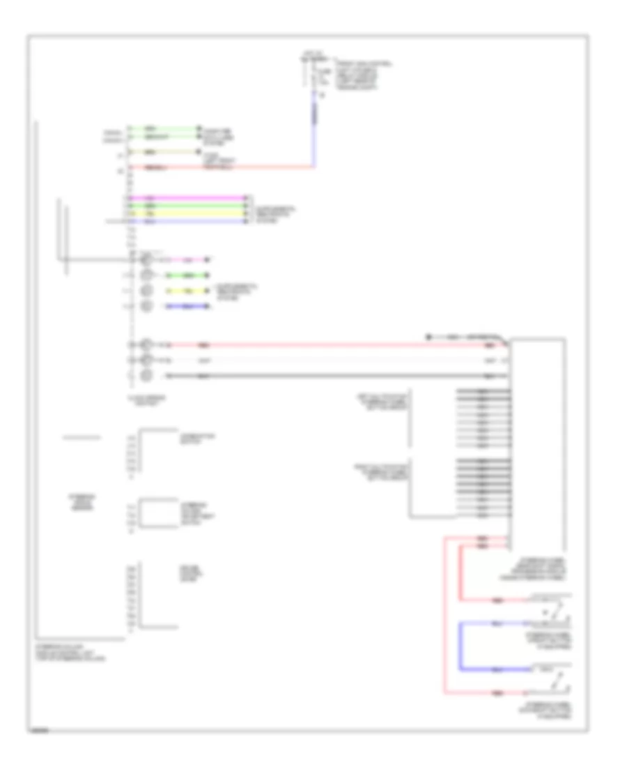
ELECTRONIC POWER STEERING Electronic Power Steering Wiring Diagram for Mercedes-Benz C300 4Matic 2008 List of elements for Electronic Power Steering Wiring Diagram for Mercedes-Benz C300 4Matic 2008: 20 Can e h Can e l Clock spring contact Combination switch Computer data lines system Cruise control lever Front sam control unit w/fuse & relay module (left rear of engine compt) Fuse 7.5a Hot at all times Left multifuntion steering wheel button group Nca Red Right multifuntion steering wheel button group Steering angle sensor Steering column adjustment switch Steering column module control unit (top of steering column) Steering wheel downshift button (if equipped) Steering wheel gear shift signal processing module (inside steering wheel) Steering wheel upshift button (if equipped) W15/5 (left front footwell)
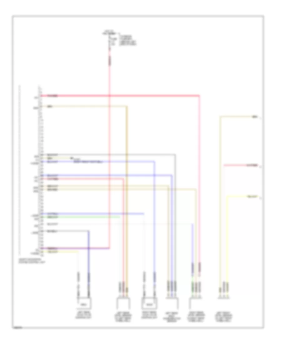
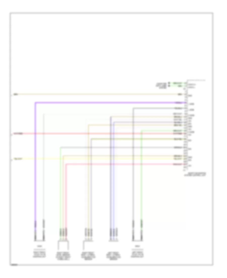
ELECTRONIC SUSPENSION Electronic Suspension Wiring Diagram (1 of 2) for Mercedes-Benz C300 4Matic 2008 List of elements for Electronic Suspension Wiring Diagram (1 of 2) for Mercedes-Benz C300 4Matic 2008: 19 (in right rear wheelwell) +5v Adaptive damping system control unit Fuse 15a Gnd H side Hot at all times Interior fuse box (behind left end of dash) L side Left front level sensor (in left front wheelwell) Left rear axle valve damping unit Left rear body acceleration sensor Left rear level sensor (in left rear wheelwell) Nca Pnk/red Right rear axle valve damping unit Right rear level sensor Sig W15/7 (right front footwell) Electronic Suspension Wiring Diagram (2 of 2) for Mercedes-Benz C300 4Matic 2008 List of elements for Electronic Suspension Wiring Diagram (2 of 2) for Mercedes-Benz C300 4Matic 2008: 15 +5v Adaptive damping system control unit Can-c h Can-c l Computer data lines system Gnd H side L side Left front axle valve damping unit Left front body lateral acceleration sensor Nca Right front axle valve damping unit Right front body lateral acceleration sensor Right front level sensor (in right front wheelwell) Sig
ENGINE PERFORMANCE
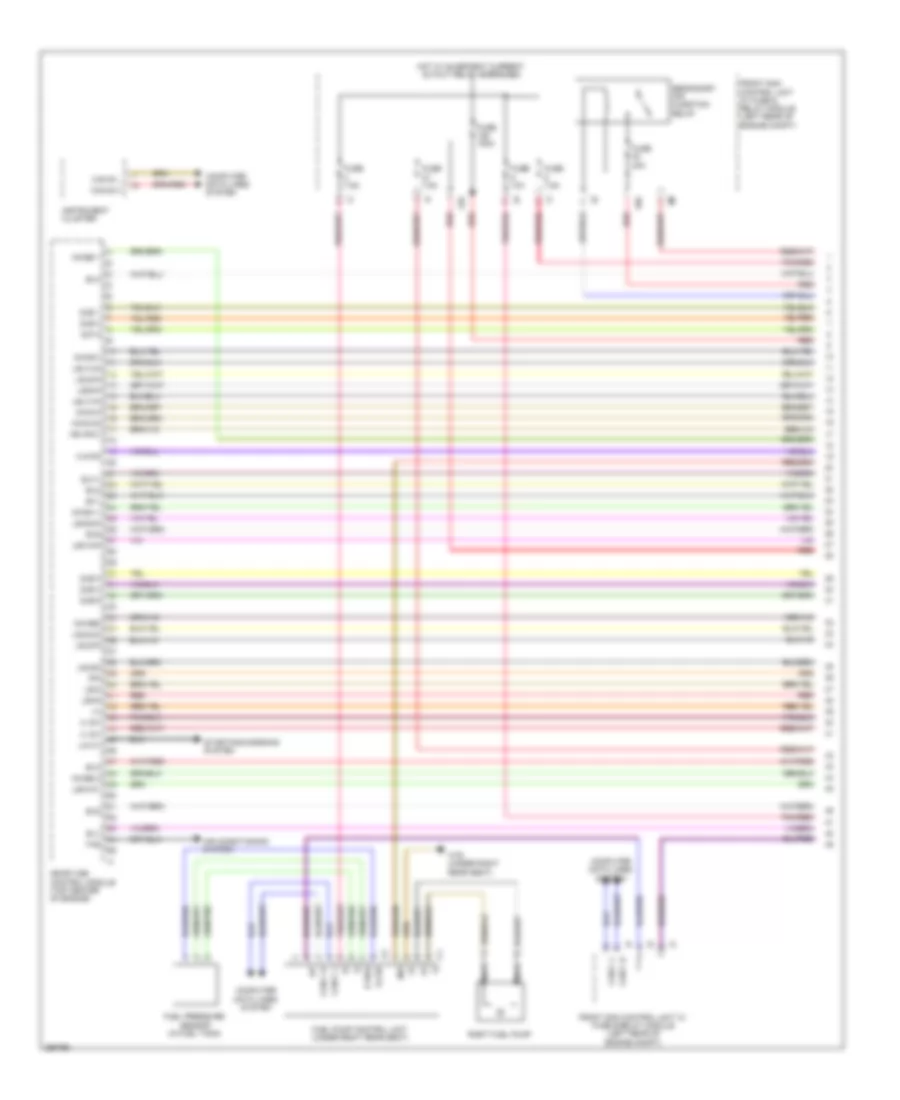
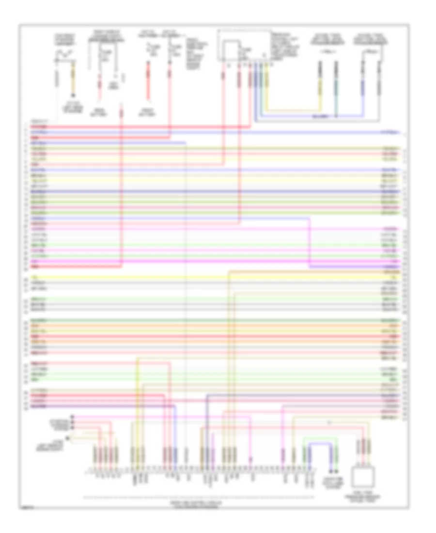
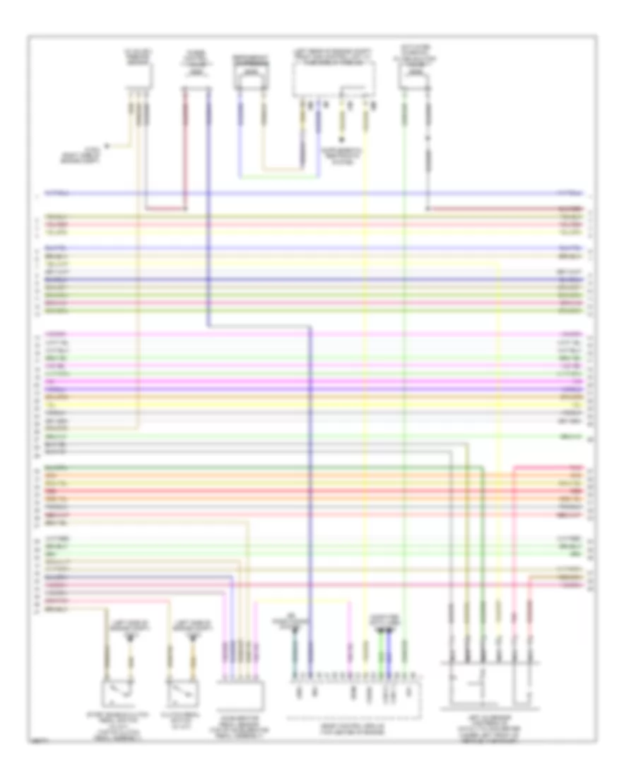
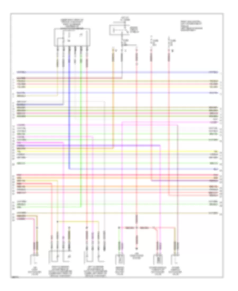
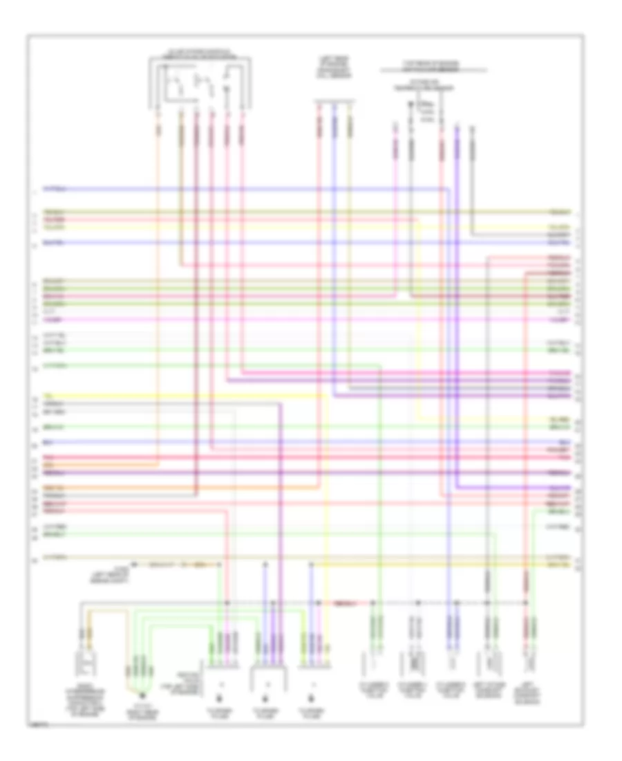
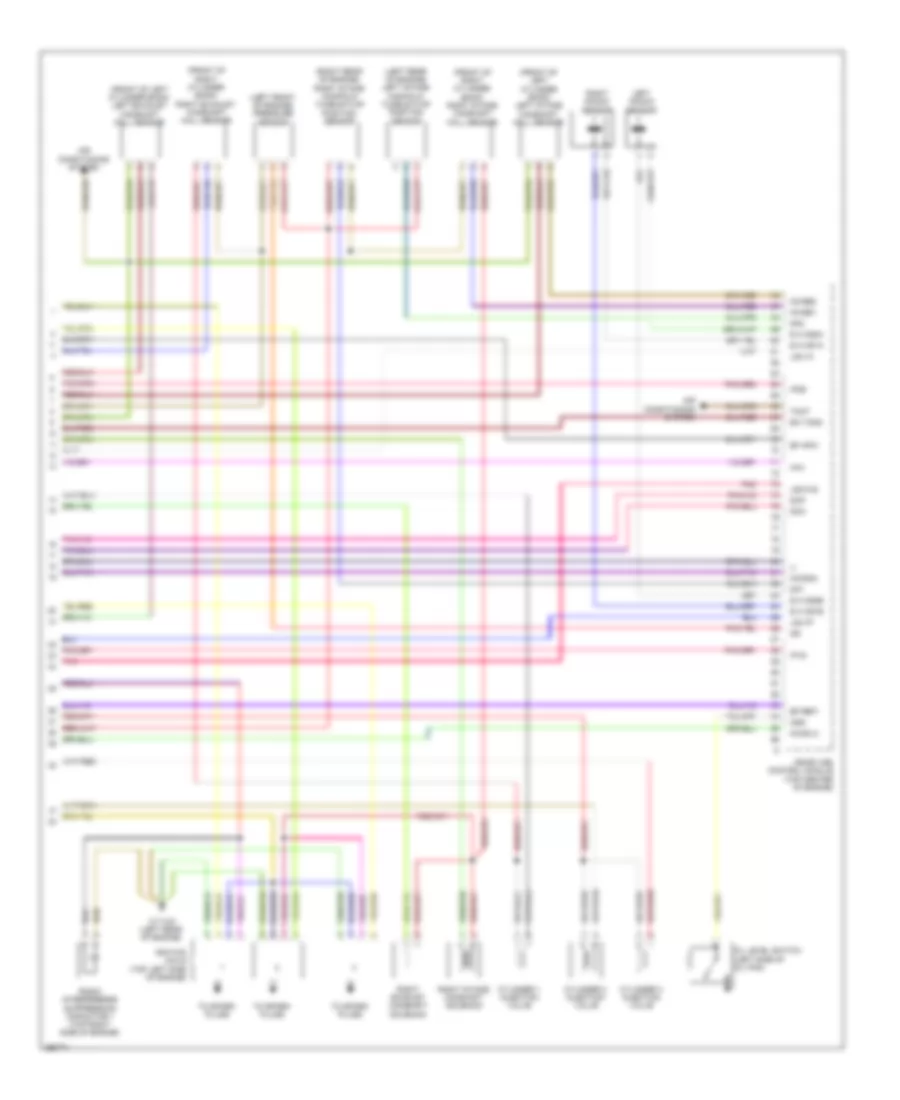
3.0L 3.0L, Engine Performance Wiring Diagram (1 of 6) for Mercedes-Benz C300 4Matic 2008 List of elements for 3.0L, Engine Performance Wiring Diagram (1 of 6) for Mercedes-Benz C300 4Matic 2008: 69 (+) (+) sh (+) sv (-) 12s 16s 30g A s dk Air conditioning system Can b h Can b l Can c h Can c l Computer data lines system E rds Ev1 Ev2 Ev3 Ev4 Ev5 Ev6 Front sam control unit w/ fuse & relay module (left rear of engine compt) Fuel pressure sensor (in fuel tank) Fuel pump control unit (under right rear seat) Fuse 10a Fuse 150a Fuse 40a Fuse 7.5a Hot w/ quiescent current cutout relay energized Instrument cluster Ipm Lin c1 Ls2hk Lsh1hk Lsh2hk Lshk Lshvk1 Lsik Lsu1un Lsu1vm Lsu2ia Lsu2ip Lsu2m Lsu2un Me-sfi (me) control module (top center of engine) Mr hfm1 Nca Nwae2 Nwg m Nwg m2 Nwga1 Nwsa 1 Nwse 1 Nwse 2 Pnk/red Red Right fuel pump Secondary air injection relay Slv Starting/charging system Suv1 Ths W76 (under right rear seat) Zue 1 Zue 2 Zue 3 Zue 4 Zue 6 Zuf 5 3.0L, Engine Performance Wiring Diagram (2 of 6) for Mercedes-Benz C300 4Matic 2008 List of elements for 3.0L, Engine Performance Wiring Diagram (2 of 6) for Mercedes-Benz C300 4Matic 2008: 38 (+) sv (in fuel tank) left fuel level indicator sensor (in fuel tank) right fuel level indicator sensor (not used) (right side of luggage compt) rear prefuse box (top front of engine) air pump C111 Can c h Can e h Computer data lines system Dst Ekp Front battery Front electrical prefuse box (at right rear of engine compt) Fuel tank pressure sensor (in fuel tank) Fuse 125a Fuse 20a Fuse 60a Hot at all times Kup1 Kup2 Lin Me-sfi (me) control module (top center of engine) Nca Pnk/red Rear battery Rear sam control unit w/ fuse & relay module (left side of trunk/cargo area) Red Senm1 Slp Sp1m Sp1s Sp2s Starting/ charging system Str U pwg1 W11w2 (left rear of engine) W16/5 (left rear of engine compt) 3.0L, Engine Performance Wiring Diagram (3 of 6) for Mercedes-Benz C300 4Matic 2008 List of elements for 3.0L, Engine Performance Wiring Diagram (3 of 6) for Mercedes-Benz C300 4Matic 2008: 27 (left rear of engine compt) front sam control unit w/ fuse & relay module (left side of engine compt) w16/3 (w/ sulev) premair sensor 18m 20m 21m Aav Accelerator pedal sensor (top of accelerator pedal assembly) Activated charcoal filter shutoff valve Air conditioning system Can c l Can e l Clutch pedal switch (w/ m/t) Computer data lines system Crash Left o2 sensor upstream of catalytic converter (under left front of vehicle, in exhaust) Lues Me-sfi control module (top center of engine) Nca Pnk Purge control valve Red Refrigerant compressor Reg Sp2m Start enable clutch pedal switch (w/ m/t) (top of clutch pedal assembly) W16/4 (right side of engine compt) 3.0L, Engine Performance Wiring Diagram (4 of 6) for Mercedes-Benz C300 4Matic 2008 List of elements for 3.0L, Engine Performance Wiring Diagram (4 of 6) for Mercedes-Benz C300 4Matic 2008: 17 (under right front of vehicle, in exhaust) right o2 sensor upstream of catalytic converter Air conditioning system Air pump switchover valve Engine circuit 87 relay Front sam control unit w/fuse & relay module (left rear of engine compartment) Fuse 15a Fuse 20a Fuse 5a Heating system shutoff valve Hot at all times Intake manifold switchover valve Intake manifold tumble flap switchover valve Left o2 sensor downstream of catalytic converter (under left front of vehicle, in exhaust) Nca Pnk Red Right o2 sensor downstream of catalytic converter (under right front of vehicle, in exhaust) 3.0L, Engine Performance Wiring Diagram (5 of 6) for Mercedes-Benz C300 4Matic 2008 List of elements for 3.0L, Engine Performance Wiring Diagram (5 of 6) for Mercedes-Benz C300 4Matic 2008: 15 (in air intake manifold) throttle valve actuator (left rear of engine) crankshaft hall sensor (top rear of engine) hot film maf sensor Cylinder 4 injection valve Cylinder 5 injection valve Cylinder 6 injection valve Ignition coils (top left side of engine) Intake air temperature sensor Left exhaust camshaft solenoid Left intake camshaft solenoid Pnk Radio interference suppression capacitor 2 (top left side of engine) To spark plugs W11w1 (right rear of engine) W16/5 (left rear of engine compt) 3.0L, Engine Performance Wiring Diagram (6 of 6) for Mercedes-Benz C300 4Matic 2008 List of elements for 3.0L, Engine Performance Wiring Diagram (6 of 6) for Mercedes-Benz C300 4Matic 2008: 46 (-) (front of left cylinder bank) left exhaust camshaft hall sensor (front of left cylinder bank) left intake camshaft hall sensor (front of right cylinder bank) right exhaust camshaft hall sensor (front of right cylinder bank) right intake camshaft hall sensor (left front of engine) pressure sensor (left rear of engine) left intake manifold tumble flap position sensor (right rear of engine) right intake manifold tumble flap position sensor Air conditioning system Cylinder 1 injection valve Cylinder 2 injection valve Cylinder 3 injection valve Dcm Dcp Dk1 Dk2 E a ks1a E a ks1b E a ks2a E a ks2b Ea tans Ef hfm1 Ef ref1 Hav Ignition coils (top left side of engine) Ip1s Ip2s Kwdga Left knock sensor Lshvk2 Lsu1a Lsu1p Me-sfi (me) control module (top center of engine) Nwge1 Nwge2 Nwsa 2 Oil level switch (left side of oil pan) Oss Pnk Radio interference suppression capacitor 1 (top right side of engine) Right exhaust camshaft solenoid Right intake camshaft solenoid Right knock sensor Tmot To spark plugs W11w2 (left rear of engine)
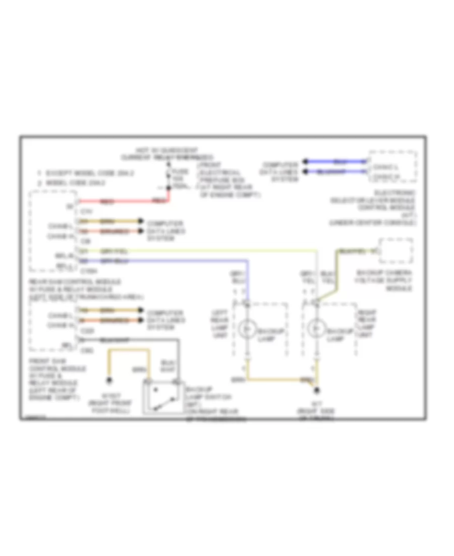
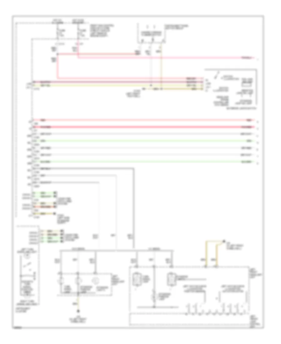
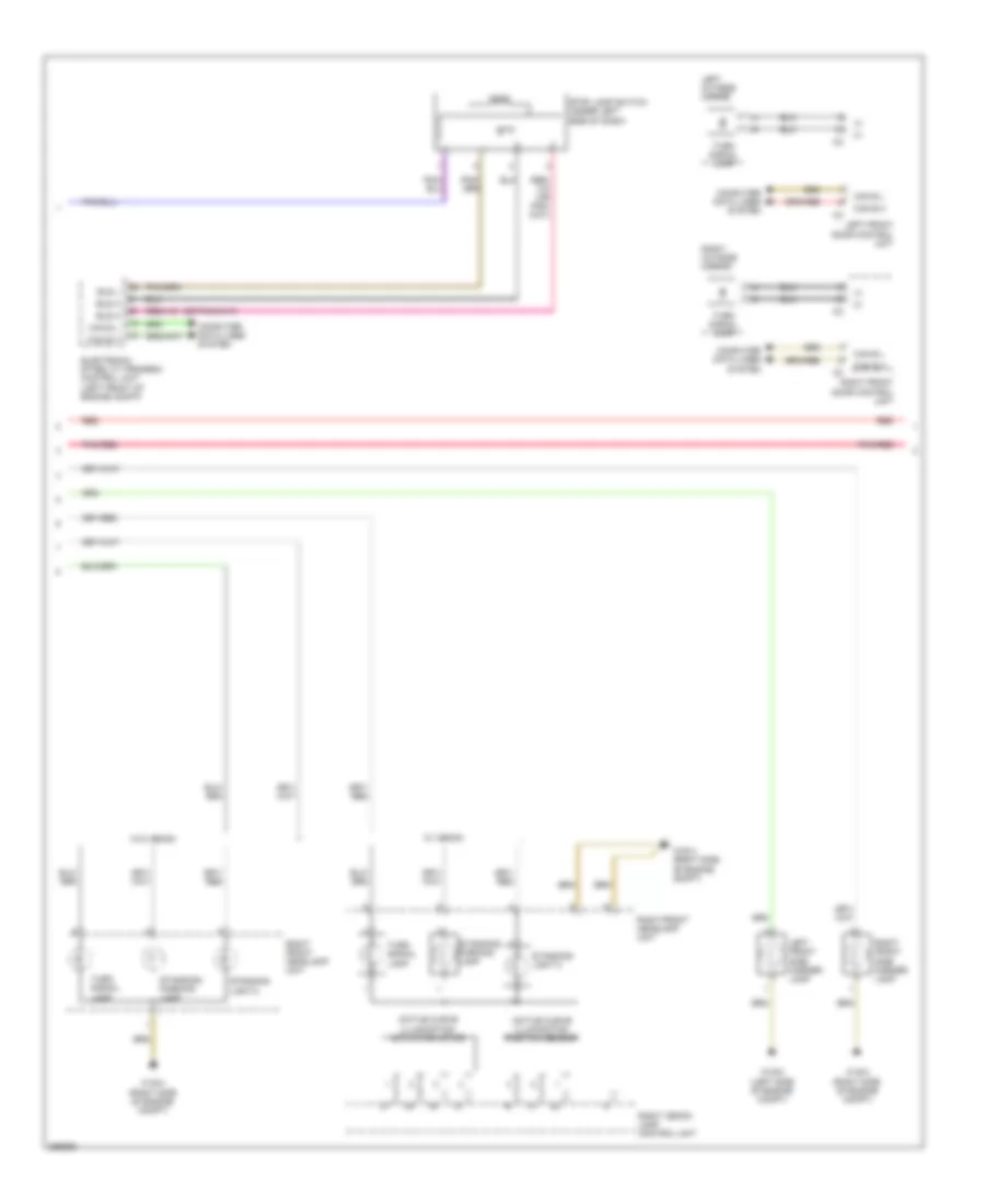
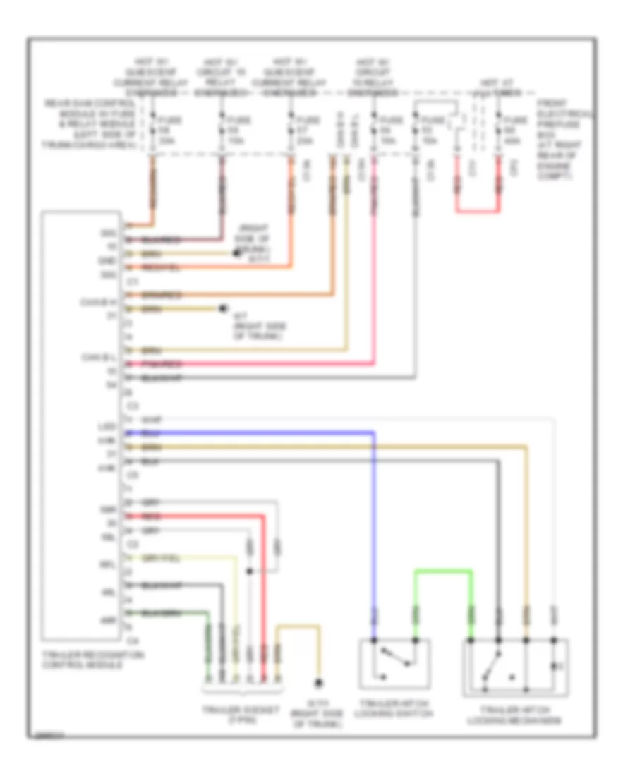
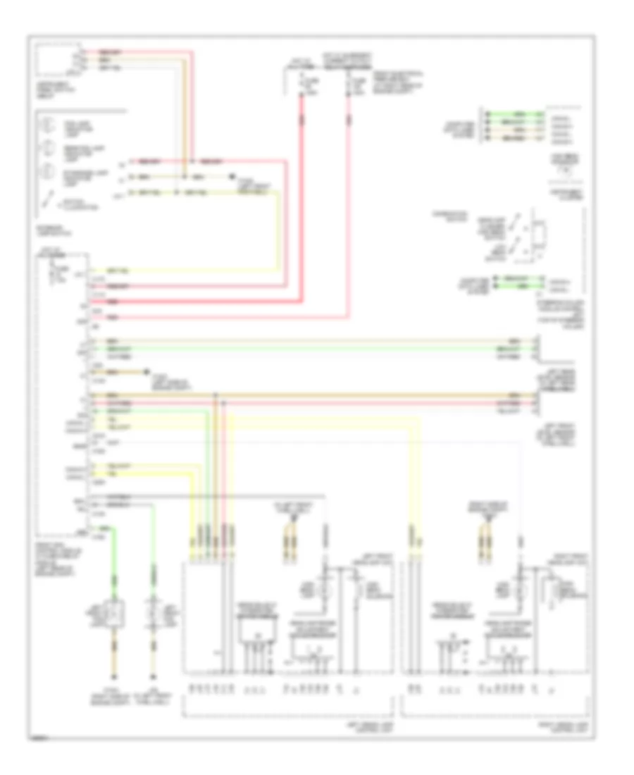
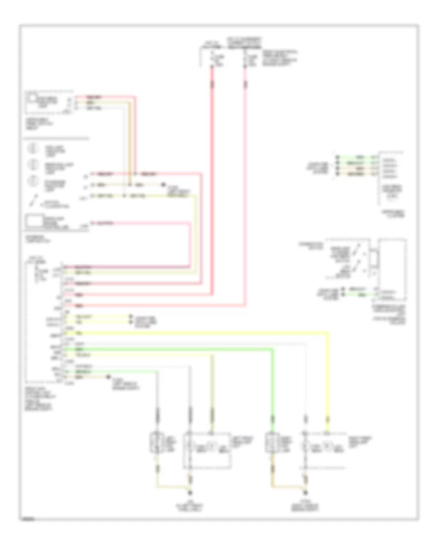
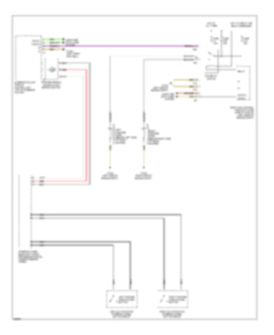
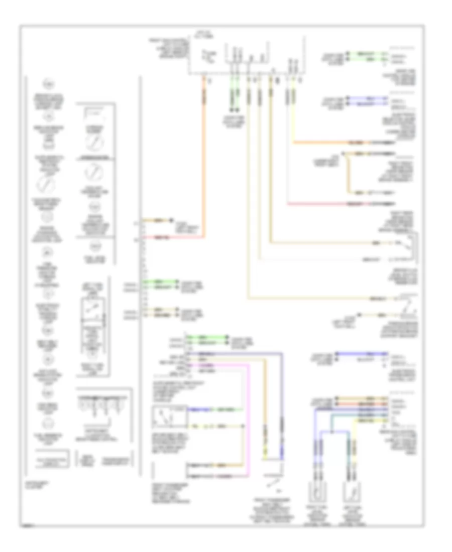
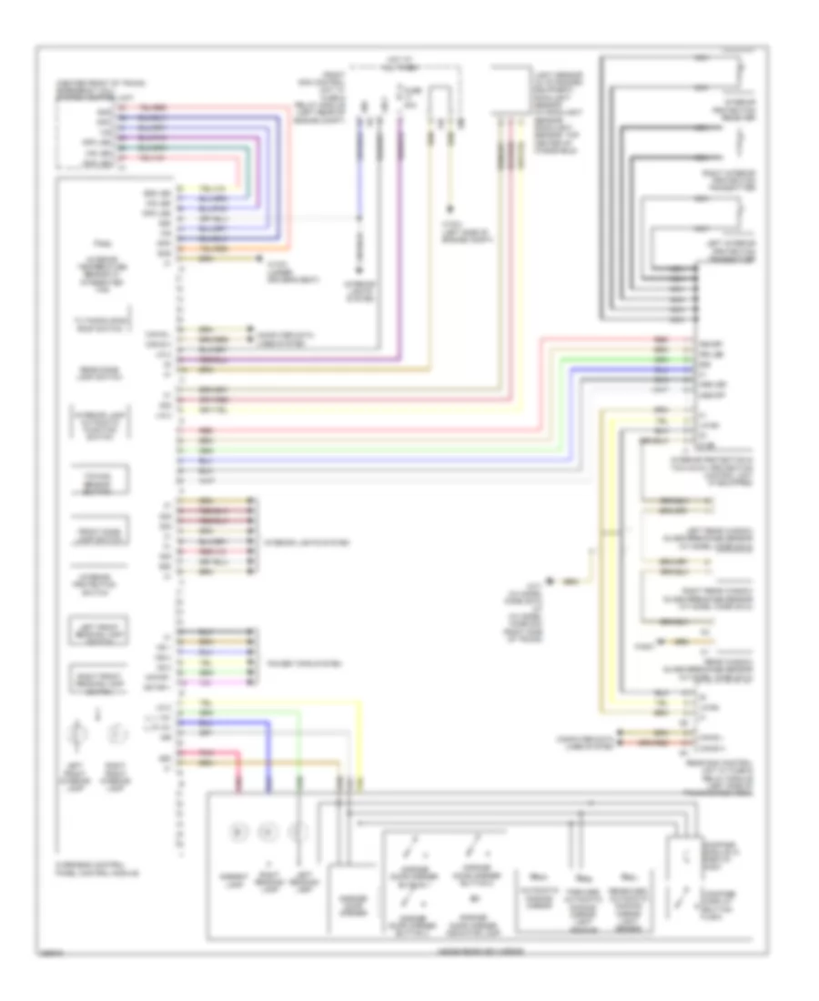
EXTERIOR LIGHTS Backup Lamps Wiring Diagram for Mercedes-Benz C300 4Matic 2008 List of elements for Backup Lamps Wiring Diagram for Mercedes-Benz C300 4Matic 2008: 29 Backup lamp Backup lamp switch (m/t) (on right rear of transmission) C15h C1v C22i C9g C9i Can-b h Can-b l Can-c h Can-c l Computer data lines system Electronic selector lever module control module (a/t) (under center console) Except model code 204.2 Front electrical prefuse box (at right rear of engine compt) Front sam control module w/ fuse & relay module (left rear of engine compt) Fuse 150a Hot w/ quiescent current relay energized Left rear lamp unit Model code 204.2 Module Rear sam control module w/ fuse & relay module (left side of trunk/cargo area) Red Rfl Rfl-l Rfl-r Right rear lamp unit W15/7 (right front footwell) W7 (right side of trunk) Exterior Lamps Wiring Diagram (1 of 3) for Mercedes-Benz C300 4Matic 2008 List of elements for Exterior Lamps Wiring Diagram (1 of 3) for Mercedes-Benz C300 4Matic 2008: 52 16s 49l 49r 58l 58r Acoustic turn signal function check C11c C14m C15m C17c C18m C19i C20m C21m C22i C7i Can b h Can b l Can e h Can e l Computer data lines system Exterior lights switch Fog lamp ind lamp Front sam control module w/ fuse & relay module (left rear of engine compt) Fuse 7.5a Hazard warning flasher switch Headlamp range controller (w/o xenon) Hot at all times Hot in on or start Instrument cluster Instrument panel switch group Left active curve illumination actuator motor Left active curve illumination position sensor Left front headlamp unit Left turn signal ind light Left xenon lamp control unit Lin 1 Lwr Pnk/red Rear fog lamp ind lamp Red Right turn signal ind light Standing lamp ind lamp Standing light 2 Standing/ parking lamp Switch illumination Turn signal lamp W/ xenon W/o xenon W15/5 (left front footwell) W16/3 (left side of engine compt) W9 (in left front wheelwell) Exterior Lamps Wiring Diagram (2 of 3) for Mercedes-Benz C300 4Matic 2008 List of elements for Exterior Lamps Wiring Diagram (2 of 3) for Mercedes-Benz C300 4Matic 2008: 30 (+) Active curve illumination actuator motor Active curve illumination position sensor Bls h Bls l Bls m Can b h Can b l Can e h Can e l Computer data lines system Electronic stability program control unit (left front of engine compt) Left front door control unit Left front side marker lamp Left outside mirror Pnk/red Red Right front door control unit Right front headlamp unit Right front side marker lamp Right outside mirror Right xenon lamp control unit Standing light 2 Standing/ parking lamp Stop lamp switch (under left side of dash) Turn signal lamp W/ xenon W/o xenon W16/3 (left side of engine compt) W16/4 (right side of engine compt) Exterior Lamps Wiring Diagram (3 of 3) for Mercedes-Benz C300 4Matic 2008 List of elements for Exterior Lamps Wiring Diagram (3 of 3) for Mercedes-Benz C300 4Matic 2008: 52 (w/ standard equipment) light sensor 15r 30g 49r 58l 6hd Bsl l Bsl r C30 C5h C6hd C7i C9i Can b h Can b l Can e h Can e l Center stop lamp Combination switch Computer data lines system Cp2 Except model code 204.2 Flasher/ high beam switch Fog lamp Front electrical prefuse box (at right rear of engine compt) Fuse 125a Fuse 40a Headlamp Hot at all times Inner stop/ tail lamp Left license plate lamp Left rear lamp unit Lin 2 Model code 204.2 Nsl r Overhead control panel control module (w/ can) overhead control panel electronics (w/o can) Pnk Pnk/red Rain/light sensor (w/ rain/light sensor) (top center of windshield) Rear sam control module w/ fuse & relay module (left side of trunk/cargo area) Red Right license plate lamp Right rear lamp unit Side marker lamp Sl l Sl r Steering column module control unit (top of steering column) Stop/ tail/ park lamp Turn signal lamp Turn signal lamps switch W15/5 (left front footwell) W7 (right side of trunk) Trailer Light Wiring Diagram for Mercedes-Benz C300 4Matic 2008 List of elements for Trailer Light Wiring Diagram for Mercedes-Benz C300 4Matic 2008: 33 (right side of trunk) w7/1 30g 49l 49r 58l 58r Ahk C13a C15h C1v Can b h Can b l Cp2 Front electrical prefuse box (at right rear of engine compt) Fuse 15a Fuse 20a Fuse 30a Fuse 40a Gnd Hot at all times Hot w/ circuit 15 relay energized Hot w/ quiescent current relay energized Led Pnk/red Rear sam control module w/ fuse & relay module (left side of trunk/cargo area) Red Rfl Trailer hitch locking mechanism Trailer hitch locking switch Trailer recognition control module Trailer socket (7-pin) W7 (right side of trunk) W7/1 (right side of trunk)
GROUND DISTRIBUTION Ground Distribution Wiring Diagram (1 of 2) for Mercedes-Benz C300 4Matic 2008 List of elements for Ground Distribution Wiring Diagram (1 of 2) for Mercedes-Benz C300 4Matic 2008: 26 Air pump, radio interference suppression capacitor 1, cylinder 1 ignition coil, cylinder 2 ignition coil & cylinder 3 ignition coil Battery sensor Condensation sensor for fuel filter w/ heating element Cylinder 1 ignition coil, cylinder 2 ignition coil, cylinder 3 ignition coil, cylinder 4 ignition coil & radio interference suppression capacitor 2 Cylinder 5 ignition coil, cylinder 6 ignition coil, cylinder 7 ignition coil, cylinder 8 ignition coil & radio interference suppression capacitor 1 Electronic selector lever module control module (a/t), left front reversible emergency testing retractor (if equipped), left front door control unit, driver seat control unit, instrument panel parktronic warning indicator (w/ city assist system), left rear seat belt buckle switch (if equipped), left rear backrest inclination switch, left rear door lock, left rear door control unit, left front seat sitting surface heated cushion, left front backrest heated cushion, driver seat partially electric seat adjustment switch (if equipped), left front seat adjustment switch group (if equipped), driver seat lumbar support adjustment control unit (if equipped), driver seat lumbar support pneumatic pump (if equipped), left trunk lid ambient lamp & warning lamp (model code 204.2), left trunk lamp (model code 204.2), driver side air bag squib & driver pelvis air bag squib Radio interference suppression capacitor 2, cylinder 4 ignition coil, cylinder 5 ignition coil & cylinder 6 ignition coil Rear sam control module w/ fuse & relay module, interior protection & tow away protection control unit shield (if equipped), trailer socket, trailer recognition control module, left inner radar sensor-rear bumper, left outer radar sensor-rear bumper, right outer radar sensor-rear bumper, right inner radar sensor-rear bumper, rear bass speaker amplifier (if equipped), tailgate control button, right rear seat belt buckle switch (if equipped), center rear seat belt buckle switch (if equipped), left rear backrest lock switch (if equipped), right rear backrest lock switch (if equipped), center stop lamp, left license plate lamp, right license plate lamp, trunk lid central locking motor, trunk lid external operation switch, right trunk lid ambient lamp & warning lamp, tailgate wiper motor, dvd player (if equipped), left rear display (if equipped) & right rear display (if equipped) Rear sam control module w/ fuse & relay module, right trunk lamp, left rear lamp unit, left rear side marker lamp, right rear lamp unit, right rear side marker lamp, keyless go control unit (if equipped), tailgate control button (if equipped), right rear seat belt buckle switch (if equipped), center rear seat belt buckle switch, center stop lamp, trunk lid keyless go button (if equipped), trunk lid emergency opening switch, trailer recognition control module, trailer socket (7 pin), right license plate lamp, left license plate lamp, trunk lid central locking motor, trunk lid external operation switch, trunk lid contact switch, right trunk lid ambient lamp & warning lamp, tailgate wiper motor, cargo area socket, trunk lid ambient lamp, special purpose vehicle multi-function control unit, taxi peripheral device electrical connector, radio data transmission keyboard electrical connector 1, two way radio electrical connector, taximeter electrical connector, taxi emergency alarm system "delete" button & taxi emergency alarm system "trigger" button Spray nozzle heater (if equipped), wiper park heater (if equipped), spray nozzle hose heater (if equipped), left fog light (w/ standard equipment), combustion engine & air conditioning w/ integrated control fan motor & left front headlamp unit Tire pressure monitor control unit (if equipped), reverse camera control module (if equipped), multicontour seat pneumatic pump (if equipped), sound system amplifier control unit (if equipped), tailgate control unit (if equipped), satellite digital audio radio (sdar) control unit (if equipped), digital audio broadcasting control unit (if equipped), overhead control panel control module (if equipped), overhead control panel electronics (if equipped), emergency call system control unit (if equipped) & frequency switchover control unit Vehicle floor chassis can voltage distributor electrical connector, left vehicle floor interior can voltage distributor electrical connector, telematics can voltage distributor electrical connector & potential distributor electrical connector W10 (near battery) W11 (right front of engine) W11/1 (left front of engine) W11w1 (right rear of engine) W11w2 (left rear of engine) W12 W15/6 (left front footwell) W18 (under driver's seat) W18/3 (under driver's seat) W33/4 W6/1 W7 (right side of trunk) W7/1 (right side of trunk) W9 (in left front wheelwell) Ground Distribution Wiring Diagram (2 of 2) for Mercedes-Benz C300 4Matic 2008 List of elements for Ground Distribution Wiring Diagram (2 of 2) for Mercedes-Benz C300 4Matic 2008: 30 Control unit Drive train can voltage distributor electrical connector & potential distributor Electrical connector Electronic stability program Electronic transmission control unit, adaptive damping system control unit, parktronic control unit (if equipped), fully integrated transmission control unit, ac housing, backup lamp switch (m/t), electronic toll collection control unit (if equipped), alarm siren (if equipped), left outer radar sensor-front bumper (w/ city assist system), left inner radar sensor-front bumper (w/ city assist system), right inner radar sensor-front bumper (w/ distronic plus), right outer radar sensor-front bumper (w/ distronic plus), distronic electric controller unit & radar sensors control unit Front electrical prefuse box, clutch pedal switch (m/t), start enable clutch pedal switch left front side marker lamp, engine hood anti theft alarm system switch (if equipped), windshield washer system pump, headlamp cleaning system pump & left fanfare horn Fuel pump control Me-sfi (me) control module, front sam control module w/ fuse & relay module, cylinder 1 ignition coil, cylinder 2 ignition coil, cylinder 3 ignition coil, cylinder 4 ignition coil, cylinder 5 ignition coil & cylinder 6 ignition coil Module Ptc heater booster Rear window glass breakage Rear window interference suppression capacitor 1 Rear window interference suppression capacitor 2 Right fanfare horn, premair sensor, right front headlamp unit (w/ xenon headlamps), right front side marker lamp, right fog light & coolant circulation pump (w/ 3 zone thermotronic) Right front reversible emergency tensioning retractor (if equipped), front cigarette lighter w/ astray illumination, right fuel pump, right front brake wear sensor, right rear brake wear sensor, right front door control unit, front passenger seat control unit, right rear backrest inclination switch (if equipped), vehicle interior power outlet (w/ rear socket), right rear door lock (w/o keyless go), right rear door control unit, right front seat sitting surface heated cushion, right front backrest heated cushion, front passenger seat partially electric seat adjustment switch (if equipped), right front seat adjustment switch group (w/o memory), front passenger seat lumbar support adjustment control unit (if equipped), front passenger seat lumbar support pneumatic pump (if equipped), weight sensing system (wss) control unit (if equipped), right side air bag ignition squib, left nitrogen oxides control unit & right nitrogen oxides control unit Sensor Steering column module control unit, electronic ignition switch control unit, automatic air conditioning control & operating unit, instrument cluster, upper control panel control unit, exterior lights switch, instrument panel switch group, electric steering lock control unit, media interface control unit (w/ aux jack), glove box lamp, parking brake indicator switch, diagnostic connector, radio, audio/comand control panel, glove box socket (if equipped), audio/comand display (if equipped), mobile phone electrical connector (if equipped), right front footwell lamp (if equipped), left front footwell lamp (if equipped), interior temperature sensor (w/ 2-zone thermatic), rear blower motor (w/ 3-zone thermotronic), left center air outlet symbol illumination (if equipped), right center air outlet symbol illumination (if equipped), left front side air outlet symbol illumination (if equipped), right front side air outlet symbol illumination (if equipped) & rear air outlet symbol illumination W15/5 (left front footwell) W15/7 (right front footwell) W15/8 (right front footwell) W15/9 W16/3 (left side of engine compt) W16/4 (right side of engine compt) W16/5 (left rear of engine compt) W19 (under right front seat) W29/3 W29/4 W48/2 W70 (left front of engine compt) W76 (under right rear seat)
HEADLIGHTS Headlights Wiring Diagram, with Xenon Lamps for Mercedes-Benz C300 4Matic 2008 List of elements for Headlights Wiring Diagram, with Xenon Lamps for Mercedes-Benz C300 4Matic 2008: 61 (in left front whellwell) w9 (right side of (right side of engine compt) w16/4 30g 55l 55r 56al 56ar C11c C14m C15m C17c C20m C21m C22i Can b h Can b l Can e h Can e l Can-g h Can-g l Combination switch Computer data lines system Engine compt) Exterior lamp switch Fog lamp indicator lamp Front electrical prefuse box (at right rear of engine compt) Front sam control module w/ fuse & relay module (left rear of engine compt) Fuse 100a Fuse 125a Fuse 7.5a Headlamp flasher/ high beam switch Headlamp range adjustment actuator motor High beam indicator High beam lamp High beam solenoid Hot at all times Hot w/ quiescent current cutout relay energized Instrument cluster Instrument panel switch group Left front fog lamp Left front headlamp unit Left front level sensor (in left front whellwell) Left rear level sensor (in left rear whellwell) Left xenon lamp control unit Lin 1 Low beam switch Rear fog lamp indicator lamp Red Right front headlamp unit Right xenon lamp control unit S16 Sig Standings lamp indicator lamp Steering column module control unit (top of steering column) Switch illumination W15/5 (left front footwell) W16/3 (left side of engine compt) W16/4 W9 (in left front whellwell) Xenon bulb w/ integrated ignition module Headlights Wiring Diagram, without Xenon Lamps for Mercedes-Benz C300 4Matic 2008 List of elements for Headlights Wiring Diagram, without Xenon Lamps for Mercedes-Benz C300 4Matic 2008: 54 30g 55l 55r 56a r 56al 56b l 56b r C11c C14m C15m C17c C20m Can b h Can b l Can e h Can e l Can g h Can g l Combination switch Computer data lines system Exterior lamp switch Fog lamp indicator lamp Front electrical prefuse box (at right rear of engine compt) Front sam control unit w/ fuse & relay module (left rear of engine compt) Fuse 100a Fuse 125a Fuse 7.5a Headlamp flasher/ high beam switch Headlamp range controller High beam High beam indicator High beam indicator lamp Hot at all times Hot w/ quiescent current cutout relay energized Instrument cluster Instrument panel switch group Left front fog lamp Left front headlamp unit Lin 1 Low beam Low beam switch Lwr Rear fog lamp indicator lamp Red Right front fog lamp Right front headlamp unit S16 Standings indicator lamp Steering column module control unit (top of steering column) Switch illumination W15/5 (left front footwell) W16/3 (left side of engine compt) W16/4 (right side of engine compt) W9 (in left front whellwell)
HORN Horn Wiring Diagram for Mercedes-Benz C300 4Matic 2008 List of elements for Horn Wiring Diagram for Mercedes-Benz C300 4Matic 2008: 32 15m 22i C5c Can b h Can b l Can e h Can e l Computer data lines system Fan relay module Fanfare horns & air bag clock spring contact Front sam control module w/ fuse & relay module (left rear of engine compt) Fuse 31a 15a Fuse 31b 15a Fuse 7.5a Hot at all times Hot w/ circuit 15r relay energized Left fanfare horn (behind left side of front bumper) Left fanfare horn system button Left multifunction steering wheel button group M14 M15 Nca Red Relay Right fanfare horn (behind right side of front bumper) Right fanfare horn system button Right multifunction steering wheel button group Steering column module control unit (top of steering column) Steering wheel gear shift signal processing module (inside steering wheel) W15/5 (left front footwell) W16/3 (left side of engine compt) W16/4 (right side of engine compt)
INSTRUMENT CLUSTER Instrument Cluster Wiring Diagram for Mercedes-Benz C300 4Matic 2008 List of elements for Instrument Cluster Wiring Diagram for Mercedes-Benz C300 4Matic 2008: 64 11c 19i 20m 22i Acoustic turn signal light function check Antilock brake system indicator lamp Bbv hl Bbv hr Bfs Brake fluid & parking brake warning lamp (except usa) Brake fluid level switch (in brake fluid reservoir) Can b h Can b l Can c h Can c l Can e h Can e l Computer data lines system Coolant temperature gauge Driver seat belt buckle restraint systems switch (in driver's seat belt buckle) Electronic selector lever module control module (under center console) Electronic stability program warning lamp Electronic transmission control unit Engine coolant temperature malfunction indicator Engine diagnosis malfunction indicator lamp Front passenger seat belt buckle restraint systems switch (in front passenger's seat belt buckle) Front passenger seat occupied recognition (w/ seat belt reminder warning) Front sam control unit w/ fuse & relay module (left rear of engine compt) Fuel level indicator Fuel reserve indicator lamp Fuse 7.5a Gear display (prnd) Gss, bf Gss, fa High beam indicator lamp Hot at all times Instrument cluster Instrument illumination Instrument illumination brightness control Left fuel level indicator sensor (in fuel tank) Left turn signal ind lamp Me-sfi (me) control module (top center of engine) Multifunction display Nca Parking brake indicator switch (on parking brake support bracket) Rear sam control unit w/ fuse & relay module (left side of trunk/cargo area) Return line Right front brake pad wear sensor (at right front brake assembly) Right fuel level indicator sensor (in fuel tank) Right rear brake pad wear sensor (at right rear brake assembly) Right turn signal ind lamp Sbe Seat belt reminder lamp Service brake indicator lamp (usa) Sig Speedometer Tachometer & brightness sensor Tg l Tg r Tire pressure monitor warning lamp (if equipped) Transmission mode display W15/5 (left front footwell) W19 (under right front seat) Warning buzzer Overhead Console Wiring Diagram, with Sunroof for Mercedes-Benz C300 4Matic 2008 List of elements for Overhead Console Wiring Diagram, with Sunroof for Mercedes-Benz C300 4Matic 2008: 76 (center front of trunk) emergency call system control unit 13d 15m 15r 19i 30g 58d Ambient lamp Ass led Ass off Automatic dimming mirror Can b h Can b l Compass display button (usa) Compass module w/ display (usa) Computer data lines system Forward automatic dimming mirror light sensor Front dome lamp switch Front sam control unit w/ fuse & relay module (left rear of engine compt) Fuse 30a Garage door opener Garage door opener button 1 Garage door opener button 2 Garage door opener button 3 Garage door opener indicator lamp Hot at all times Hs 1 Hs 2 Hs(+) Info Info led Inside rearview mirror Interior lamp automatic function switch Interior lights system Interior protection & tow-away protection control unit (if equipped) Interior protection receiver Interior protection switch Interior temperature sensor w/ integrated fan Irs led Irs-off Left front interior lamp Left front reading lamp switch Left interior protection transmitter Left reading lamp Left rear window glass breakage sensor (w/ model code 204.2) Light sensor (w/ standard equipment) rain/light sensor (w/ rain/light sensor) (rain/light sensor: top center of windshield) Lin 2 Lin b4 Ll l 12v Ll r 12v Motor + Motor - Nca Overhead control panel control module Pnk Power tops system Rear dome lamp switch Rear sam control unit w/ fuse & relay module (left side of trunk/cargo area) Rear window glass breakage sensor (w/ model code 204.2) Rearward automatic dimming mirror light sensor Red Right front interior lamp Right front reading lamp switch Right interior protection transmitter Right reading lamp Right rear window glass breakage sensor (w/ model code 204.2) S gb Sos Sos led Tilting/sliding roof switch Towing sensor button W16/3 (left side of engine compt) W18/3 (under driver's seat) W48/2 W7/1 (w/ model code 204.2) w7 (w/ model code 204) (right side of trunk) Ws led Overhead Console Wiring Diagram, without Sunroof for Mercedes-Benz C300 4Matic 2008 List of elements for Overhead Console Wiring Diagram, without Sunroof for Mercedes-Benz C300 4Matic 2008: 75 (center front of trunk) (usa) emergency call system control unit 12v 13d 15m 19i 30 rls 30g 58d Ambient lamp Ass led Ass off Automatic air conditioning control & operating unit Automatic dimming mirror Can b h Can b l Compass display button (usa) Compass module w/ display (usa) Computer data lines system Forward automatic dimming mirror light sensor Front dome lamp switch Front sam control unit w/ fuse & relay module (left rear of engine compt) Fuse 7.5a Garage door opener Garage door opener button 1 Garage door opener button 2 Garage door opener button 3 Garage door opener indicator lamp Gnd Hot at all times Info Info led Inside rearview mirror Interior lamp automatic function switch Interior lights system Interior protection & tow-away protection control unit (if equipped) Interior protection receiver Interior protection switch Interior temperature sensor w/ integrated fan Irs led Irs-off Left front interior lamp Left front reading lamp switch Left interior protection transmitter Left reading lamp Left rear window glass breakage sensor (w/ model code 204.2) Light sensor (w/ standard equipment) rain/light sensor (w/ rain/light sensor) (rain/light sensor: top center of windshield) Lin 2 Lin b4 Ll l 12v Ll r 12v Nca Ntc Overhead control panel electronics Pnk Power tops system Rear dome lamp switch Rear sam control unit w/ fuse & relay module (left side of trunk/cargo area) Rear window glass breakage sensor (w/ model code 204.2) Rearward automatic dimming mirror light sensor Red Right front interior lamp Right front reading lamp switch Right interior protection transmitter Right reading lamp Right rear window glass breakage sensor (w/ model code 204.2) S gb Sig Sos Sos led Towing sensor button W16/3 (left side of engine compt) W18/3 (under driver's seat) W48/2 W7/1 (w/ model code 204.2) w7 (w/ model code 204) (right side of trunk) Ws led
INTERIOR LIGHTS Courtesy Lamps Wiring Diagram (1 of 2) for Mercedes-Benz C300 4Matic 2008 List of elements for Courtesy Lamps Wiring Diagram (1 of 2) for Mercedes-Benz C300 4Matic 2008: 49 (+) (right side of trunk) w7/1 11c 14m 16s 17c 22i 30g 58d 6hd C30 Can-b h Can-b l Computer data lines system Front dome lamp switch Front sam control unit w/ fuse & relay module (left rear of engine compt) Fuse 7.5a Glove box lamp Glove box lamp switch Hot in on or start Interior lamp automatic function function switch Interior protection switch Left front Left front footwell lamp Left front interior lamp Left front mirror lamp switch Left rear reading lamp Left sun visor mirror lamp Ll l 12v Ll r 12v Overhead control panel control module (w/ power glass tilting/sliding sunroof) overhead control panel electronics (w/o power glass tilting/sliding sunroof) Pnk Reading lamp switch Rear dome lamp Rear dome lamp switch Rear interior lamp Rear sam control unit w/ fuse & relay module (left side of trunk/cargo area) Red Right front Right front footwell lamp Right front interior lamp Right front mirror lamp switch Right rear reading lamp Right sun visor mirror lamp Sig W/ avantgarde & elegance W/ classic W15/5 (left front footwell) W16/3 (left side of engine compt) Courtesy Lamps Wiring Diagram (2 of 2) for Mercedes-Benz C300 4Matic 2008 List of elements for Courtesy Lamps Wiring Diagram (2 of 2) for Mercedes-Benz C300 4Matic 2008: 38 (+) (-) (in trunk lid latch assembly) trunk lid contact switch (under driver's seat) (model code 204.2) w18 w7 (except model code 204.2) (right side of trunk) (w/ interior lights package) left front door exit & warning lamp (w/ interior lights package) left rear door exit & warning lamp (w/ interior lights package) right front door exit & warning lamp (w/ interior lights package) right rear door exit & warning lamp Ambient lamp Can b h Can b l Computer data lines system Except model code 204.2 Flat wire Front electrical prefuse box (at right rear of engine compt) Fuse 125a Fuse 40a Hot at all times Inside rear view mirror Left front door control unit Left front door handle illumination (w/ interior lights package) Left reading lamp Left rear door control unit Left rear door handle illumination (w/ interior lights package) Left trunk lamp (model code 204.2) Left trunk lid ambient lamp & warning lamp Pnk Red Right front door control unit Right front door handle illumination (w/ interior lights package) Right reading lamp Right rear door control unit Right rear door handle illumination (w/ interior lights package) Right trunk lamp Right trunk lid ambient lamp & warning lamp Trunk lid external operation switch W18 (under driver's seat) W7 (right side of trunk) Instrument Illumination Wiring Diagram (1 of 2) for Mercedes-Benz C300 4Matic 2008 List of elements for Instrument Illumination Wiring Diagram (1 of 2) for Mercedes-Benz C300 4Matic 2008: 35 (under driver's seat) (model code 204.2) w18 11c 14m 16s 17c 19i 22i 30g 58d Automatic transmission mode button Can b h Can b l Can c h Can c l Computer data lines system Electronic selector lever module control module (under center console) Exterior lights switch Front cigarette lighter w/ ashtray illumination (w/ smoker package) Front sam control unit w/ fuse & relay module (left rear of engine compt) Front vehicle interior power outlet (w/o smoker package) Fuse 5a Fuse 7.5a Hot at all times Instrument cluster Instrument illumination & instrument illumination brightness control Lwr Nca Overhead control panel control module (w/ can) overhead control panel electronics (w/o can) Red Shift gate symbol illumination Switch illumination W15/5 (left front footwell) W16/3 (left side of engine compt) W18 (under driver's seat) W19 (under right front seat) Instrument Illumination Wiring Diagram (2 of 2) for Mercedes-Benz C300 4Matic 2008 List of elements for Instrument Illumination Wiring Diagram (2 of 2) for Mercedes-Benz C300 4Matic 2008: 28 (w/ tailgate control) driver tailgate control button 58d Can b h Can b l Computer data lines system Driver tailgate control button (w/ tailgate control) Flat wire Front electrical prefuse box (at right rear of engine compt) Fuse 125a Hot at all times Left center air outlet symbol illumination Left front door central locking interior switch Left front door control unit Left front side air outlet symbol illumination Left rear door control unit Left rear power window switch Nca Rear air outlet symbol illumination Red Right center air outlet symbol illumination Right front door central locking interior switch Right front door control unit Right front side air outlet symbol illumination Right rear door control unit Right rear power window switch Trunk lid release button (w/ trunk lid release) W/ air outlet symbol illumination W15/5 (left front footwell)
MEMORY SYSTEMS Driver"s Memory Seat Wiring Diagram for Mercedes-Benz C300 4Matic 2008 List of elements for Driver"s Memory Seat Wiring Diagram for Mercedes-Benz C300 4Matic 2008: 42 (under driver's seat) w18 30g C116 Can-b h Can-b l Computer data lines system Driver seat backrest incli- nation adjust- ment motor (in driver's seat back) Driver seat control unit Driver seat fore/aft adjustment motor (under driver's seat) Driver seat head restraint adjustment motor Driver seat height adjustment motor (under driver's seat) Driver seat inclination adjustment motor (under driver's seat) Fuse 30a Hot w/ quiescent current cutout relay energized Hs(+) Hs(-) Hv_hs(+) Hv_hs(-) Hv_mot+ Hv_mot- Interior fuse box (behind left end of dash) Left front door control unit Left front seat adjustment switch group Lin b5 Lv_hs(+) Lv_hs(-) Lv_mot+ Lv_mot- Mk+ Ml+ Ml/k Mls Mls h Mls v Nca Nv_hs(+) Nv_hs(-) Nv_mot+ Nv_mot- Red Steering column adjustment motor (in/out) Steering column adjustment motor (up/down) Memory Mirrors Wiring Diagram for Mercedes-Benz C300 4Matic 2008 List of elements for Memory Mirrors Wiring Diagram for Mercedes-Benz C300 4Matic 2008: 35 (+) Automatic dimming mirror C71 Can-b h Can-b l Computer data lines system Driver-side power window & outside mirror adjustment switch group Front sam control unit w/ fuse & relay module (left rear of engine compt) Fuse 30a Hori motor Hot at all times In/out motor (if equi- pped) Left front door control unit Left front seat adjustment switch group Left outside mirror Left outside mirror adjustment switch Lin b5 Mirror heating Nca Outside mirror adjustment switch Outside mirror fold-in/ fold-out switch (if equipped) Right front door control unit Right outside mirror Right outside mirror adjustment switch Sh(+) Sh(-) Sig Sig. Sv_m1 Sv_m1m2 Sv_m2 Turn signal Vert motor W18 (under driver's seat) W19 (under right front seat) Passenger"s Memory Seat Wiring Diagram for Mercedes-Benz C300 4Matic 2008 List of elements for Passenger"s Memory Seat Wiring Diagram for Mercedes-Benz C300 4Matic 2008: 37 30g C126 Can-b h Can-b l Computer data lines system Front passe- nger seat fore/aft adjustment motor (under front passenger's seat) Front passe- nger seat height adjustment motor (under front passenger's seat) Front passe- nger seat inclination adjustment motor (under front passenger's seat) Front passenger seat backrest inclination adjustment motor (in front passen- ger's seat back) Front passenger seat control unit Front passenger seat head restraint adjustment motor Fuse 30a Hot w/ quiescent current cutout relay energized Hs(+) Hs(-) Hv_hs(+) Hv_hs(-) Hv_mot+ Hv_mot- Interior fuse box (behind left end of dash) Lin b6 Lv_hs(+) Lv_hs(-) Lv_mot+ Lv_mot- Mk+ Ml+ Ml/k Nca Nv_hs(+) Nv_hs(-) Nv_mot+ Nv_mot- Red Right front door control unit Right front seat adjustment switch group W19 (under right front seat)
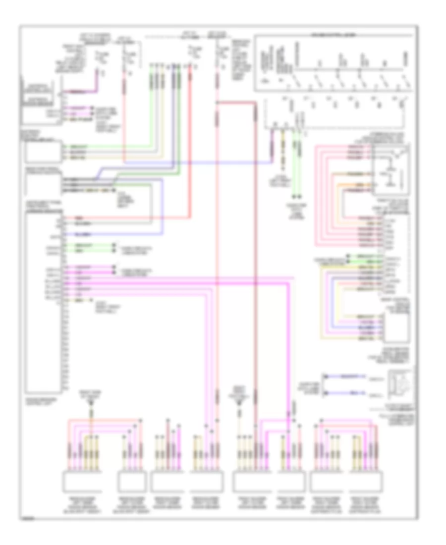
NAVIGATION Auto Pilot System Wiring Diagram for Mercedes-Benz C300 4Matic 2008 List of elements for Auto Pilot System Wiring Diagram for Mercedes-Benz C300 4Matic 2008: 76 (+) (-) (base of left "c" pillar) rear window antenna fm antenna amplifier (left front footwell) w15/5 30g Afm Am, fm & cl antenna amplifier (center front of roof) Anst Ant bt Ant gps Audio/comand display Aux gnd Aux jack electrical connector Aux l Aux r Aux shield C10t C2i Can a h Can a l Can b h Can b l Clock + Clock - Computer data lines system Data 0+ Data 0- Data 1+ Data 1- Data 2+ Data 2- Diag Fm1/am Fm2 Front sam control unit w/ fuse & relay module (left rear of engine compt) Fuse 20a Fuse 5a Gnd Gps Hl+ Hl- Hot w/ quiescent current cutout relay energized Hr+ Hr- Instrument cluster & audio/comand disply fan motor (under left side of dash) Left front door bass speaker Left front door speaker (w/o sound system) Left front door tweeter Left rear door speaker (w/o sound system) Mic 1+ Mic 2+ Mobile phone electrical connector Most in Most out Multifunction antenna Nca On/off Pnk Radio w/ auto pilot system Rear window antenna amplifier 1 (center rear of roof) Red Right front door bass speaker Right front door speaker (w/o sound system) Right front door tweeter Right rear door speaker (w/o sound system) Shield Sound systems Vl+ Vl- Voice control system microphone Vr+ Vr- W/ model code 204.0 W/ model code 204.2 W15/5 (left front footwell) Wake up COMAND Actuation Wiring Diagram (1 of 2) for Mercedes-Benz C300 4Matic 2008 List of elements for COMAND Actuation Wiring Diagram (1 of 2) for Mercedes-Benz C300 4Matic 2008: 63 (+) (-) (left front footwell) w15/5 30g Anst Audio/comand display Aux gnd Aux jack electrical connector Aux l Aux r Aux shield C10t C2i Can a h Can a l Can b h Can b l Clock + Clock - Comand control unit Computer data lines system Data 0+ Data 0- Data 1+ Data 1- Data 2+ Data 2- Diag Emergency call system control unit (center front of trunk) Front sam control unit w/ fuse & relay module (left rear of engine compt) Fuse 20a Fuse 5a Gnd Hl+ Hl- Hot w/ quiescent current cutout relay energized Hr+ Hr- Instrument cluster & audio/comand disply fan motor (under left side of dash) Left rear door speaker (w/o sound system) Mic + Mic - Mic 1+ Mic 2+ Mobile phone electrical connector Most in Most out Nca On/off Pnk Red Right rear door speaker (w/o sound system) Shield Sound systems Vl+ Vl- Voice control system microphone Vr+ Vr- W/ mobile phone pre installation W/o mobile phone pre installation W15/5 (left front footwell) Wake up COMAND Actuation Wiring Diagram (2 of 2) for Mercedes-Benz C300 4Matic 2008 List of elements for COMAND Actuation Wiring Diagram (2 of 2) for Mercedes-Benz C300 4Matic 2008: 36 (base of left "c" pillar) rear window antenna fm antenna amplifier Afm Am, fm & cl antenna amplifier (center front of roof) Ant bt Ant gps Audio shield Audio-gnd Audio-l Audio-r Canada Comand control unit Dvd player (w/ rear entertainment) Fm1/am Fm2 Global positioning system antenna splitter Gps Left front door bass speaker Left front door speaker (w/o sound system) Left front door tweeter Multifunction antenna Nca Rear window antenna amplifier 1 (center rear of roof) Right front door bass speaker Right front door speaker (w/o sound system) Right front door tweeter Shield Sound gnd Sound shield Sound-l Sound-r Usa Video-c Video-gnd Video-y W/ model code 204.0 W/ model code 204.2 Emergency Call Wiring Diagram for Mercedes-Benz C300 4Matic 2008 List of elements for Emergency Call Wiring Diagram for Mercedes-Benz C300 4Matic 2008: 48 (+) (-) 15r Ant gps Ant not C11t C19i Can-d h Can-d l Center instrument panel speaker Comand control unit Computer data lines system Crash Diagnostic connector (under left side of dash) Emergency call system antenna (center of hat shelf) Emergency call system button Emergency call system control unit (center front of trunk) Front sam control unit w/ fuse & relay module (left rear of engine compt) Fuse 7.5a Global positioning system antenna splitter (right front of trunk) Gps Hot at all times Hot w/ circuit 15r relay energized Info Info led Keep on Mb-info & breakdown assistance button Mikr + Mikr - Multifunction antenna Mute Nca Not Overhead control panel control module (w/ can) overhead control panel electronics (w/o can) Rear sam control unit w/ fuse & relay module (left side of trunk/cargo area) Shield Sig Sos Sos led Sound system amplifier control unit (left side of trunk) Tel Telediagnosis W/ navigation W/ sound system W/o navigation W/o sound system W18/3 (under driver's seat) Ws led Parktronic Wiring Diagram for Mercedes-Benz C300 4Matic 2008 List of elements for Parktronic Wiring Diagram for Mercedes-Benz C300 4Matic 2008: 51 (+) sh (+) sv (-) sh (-) sv 17c 19i C12i Can b h Can b l Can e h Can e l Center left front Center right front parktronic distance sensor Computer data lines system Front sam control unit w/ fuse & relay module (left rear of engine compt) Fuse 7.5a Hot at all times Inner left front Inner left rear parktronic distance sensor Inner right front Inner right rear parktronic distance sensor Instrument panel parktronic warning indicator Lin 1 Outer left front parktronic distance sensor Outer left rear parktronic distance sensor Outer right front parktronic distance sensor Outer right rear parktronic distance sensor Parktronic button Parktronic control unit Parktronic distance sensor Pnk/red Rear parktronic warning indicator Rear sam control unit w/ fuse & relay module (left side of trunk/cargo area) S10h S1v S2v S3v S4v S5v S6v S7h S8h S9h Upper control panel control module W v (+) W v (data) W15/7 (right front footwell) Wh (+) Wh (-) Wh (data) Wv (-)
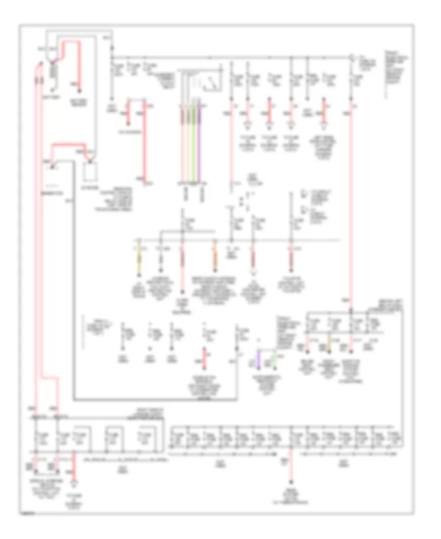
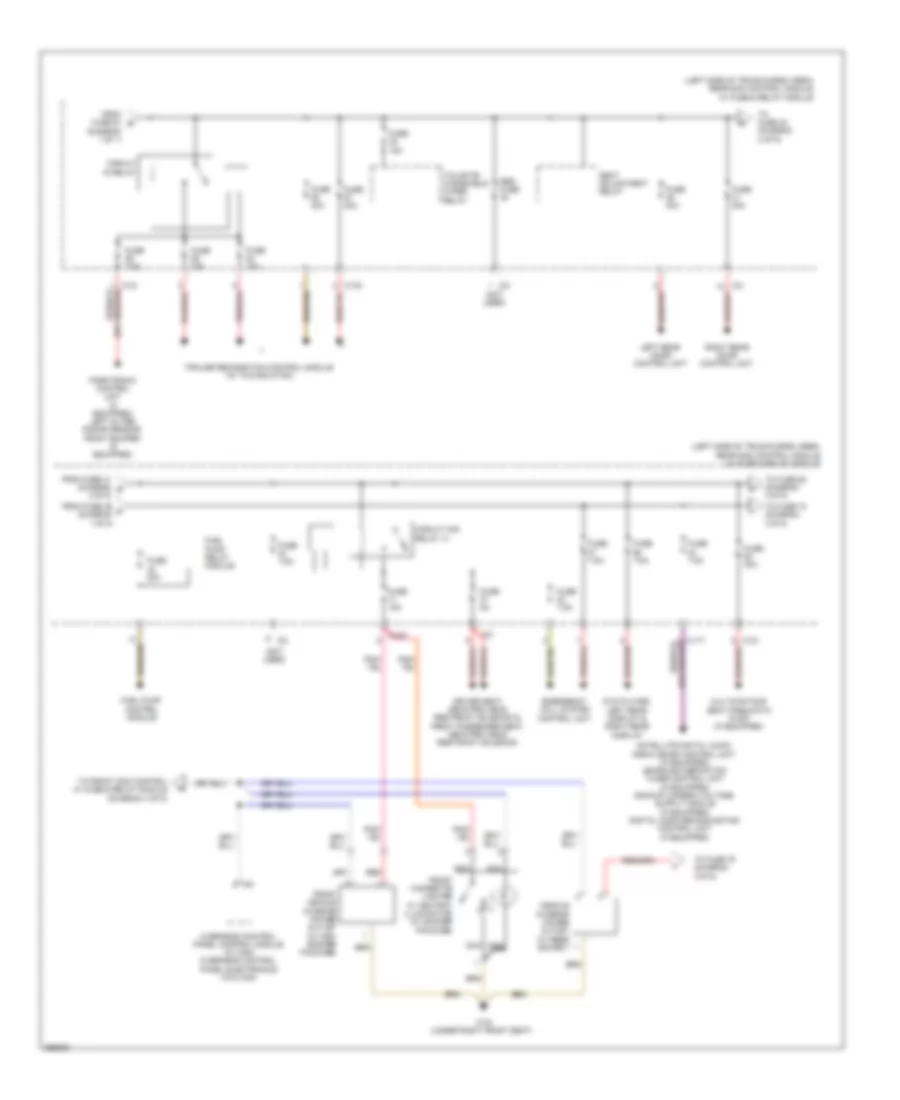
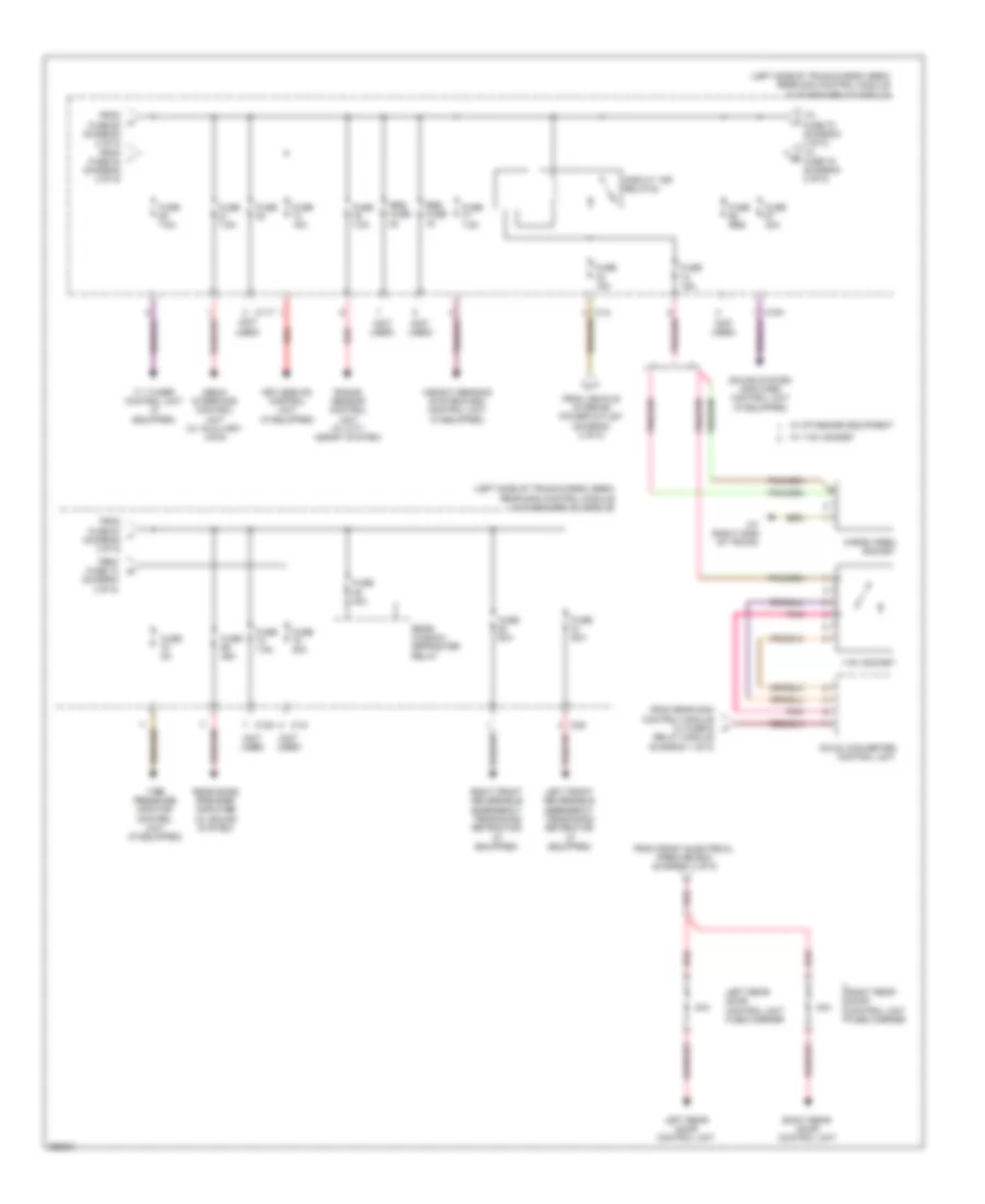
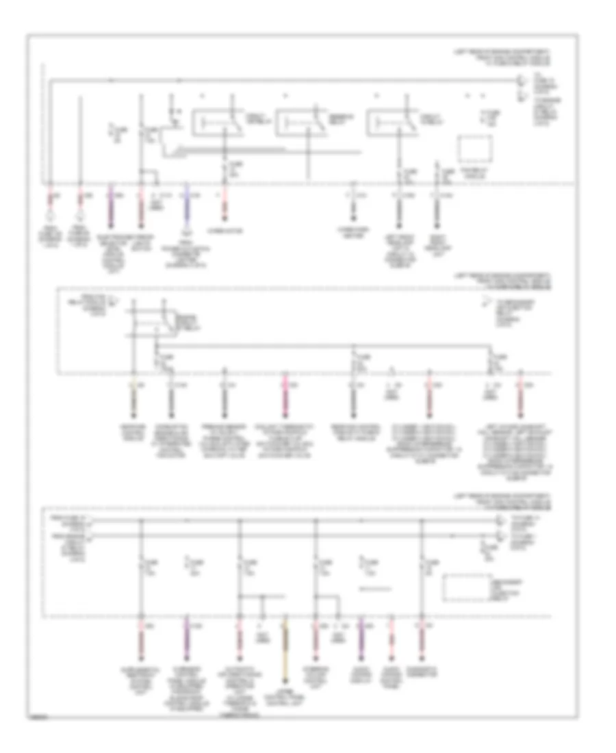
POWER DISTRIBUTION Power Distribution Wiring Diagram (1 of 5) for Mercedes-Benz C300 4Matic 2008 List of elements for Power Distribution Wiring Diagram (1 of 5) for Mercedes-Benz C300 4Matic 2008: 72 (behind left end of dash) interior fuse box (diagram 3 of 5) (not used) (right side of luggage compt) rear prefuse box A c112 A c115 A/c housing Adaptive damping system control unit (if equipped) Alarm siren (if equipped) Battery Battery sensor C111 e C112 C113 a C114 a C115 C116 C117 C126 C128 C12i C1v C2v C3i C7l C80 C8d C9i Combustion engine & air conditioning w/ integrated control fan motor Cp1 Cp2 Cp3 Driver seat control unit From fuse 103 a (diagram 1 of 1) Front electrical prefuse box (at right rear of engine compt) Front passenger seat control unit Fuse 100a Fuse 125a Fuse 150a Fuse 15a Fuse 200a Fuse 20a Fuse 25a Fuse 30a Fuse 400a Fuse 40a Fuse 60a Fuse 7.5a Fuse 70a Fuse 80a Fuse res Generator Interior protection & tow away protection control unit Left rear door control unit fuse carrier Quiescent current cutout relay Rear blower motor (w/ thermotronic) Rear sam control module w/ fuse & relay module (left side of trunk/cargo area) Rear window antenna fm antenna amplifier, rear window antenna amplifier 1, dab band iii antenna & tv1 & dab band iii antenna, Red Res fuse Rss aus Rss ein Special purpose vehicle multifunction control unit (w/ taxi) Starter Tailgate control unit (w/ automatic tailgate) To circuit 15 relay (diagram 2 of 5) To dc/ac converter control unit (diagram 3 of 5) To fuse (diagram 4 of 5) To fuse (diagram 5 of 5) To fuse 108 (diagram 1 of 5) To fuse 87 (diagram 2 of 5) W7 (right side of trunk) Power Distribution Wiring Diagram (2 of 5) for Mercedes-Benz C300 4Matic 2008 List of elements for Power Distribution Wiring Diagram (2 of 5) for Mercedes-Benz C300 4Matic 2008: 45 (diagram 1 of 1) (left side of trunk/cargo area) rear sam control module w/ fuse & relay module (not used) (or pnk/red) C11t C12i C13a C15h C3i Circuit 15 relay Circuit 15r relay (1) Driver seat neck-pro head restraint solenoid & front passenger seat neck-pro head restraint solenoid Dvd player, left rear display & right rear display Emergency call system control unit From fuse 41 (diagram g 2 0f 5) From fuse 46 c (diagram 1 0f 5) From fuse 61 b Front cigarette lighter w/ ashtray illumination (w/ smoker package) Front vehicle interior power outlet (w/ non- smoker package) Fuel pump control module Fuel pump relay module Fuse 15a Fuse 20a Fuse 30a Fuse 5a Fuse 7.5a Left rear door control unit Multicontour seat pneumatic pump (if equipped) Nca Overhead control panel control module (w/ can) overhead control panel electronics (w/o can) Parktronic control unit (if equipped) left outer radar sensor, front bumper (if equipped) Pnk/red Red Res fuse Right rear door control unit Seat adjustment relay Tailgate windshield wiper relay To front sam control w/ fuse & relay module (diagram 4 of 5) To fuse 42 (diagram 2 of 5) To fuse 74 (diagram 3 0f 5) To fuse 76 (diagram 3 0f 5) To fuse 85 (diagram 3 0f 5) Trailer recognition control module (w/ towing hitch) Vehicle interior power outlet (w/ rear socket) W19 (under right front seat) Power Distribution Wiring Diagram (3 of 5) for Mercedes-Benz C300 4Matic 2008 List of elements for Power Distribution Wiring Diagram (3 of 5) for Mercedes-Benz C300 4Matic 2008: 49 (left side of trunk/cargo area) rear sam control module w/ fuse & relay module (not used) 115v socket 30a C11t C14i C15h C2g Cargo area socket Circuit 15r relay(2) Dc/ac converter control unit Eight rear door control unit From front electrical prefuse box (diagram 1 of 5) From fuse 60 (diagram 2 of 5) from fuse 84 (diagram 2 of 5) From fuse 67 j (diagram 3 0f 5) From fuse 74 (diagram 3 0f 5) From rear sam control module w/ fuse & t From vehicle interior power outlet (daigram 2 of 5) Fuse Fuse 15a Fuse 20a Fuse 25a Fuse 40a Fuse 50a Fuse 5a Fuse 7.5a Fuse res Keyless go control unit (if equipped) Left front reversible emergency tensioning retractor (if equipped) Left rear door control unit Left rear door control unit fuse carrier Media interface control unit (w/ auxiliary jack) Pnk Radar sensor control unit (w/ city assist system) Rear bass speaker amplifier (w/ sound system) Rear window defroster relay Red Relay module (diagram 1 of 5) Res fuse Right front reversible emergency tensioning retractor (if equipped) Right rear door control unit fuse carrier Sound system amplifier control unit (if equipped) Tire pressure monitor control unit (if equipped) To fuse 70 (diagram 3 of 5) to fuse 75 (diagram 3 of 5) Tv tuner control unit (if equipped) W/ 115v socket W/ standard equipment W7 (right side of trunk) Weight sensing system(wss) control unit (if equipped) Power Distribution Wiring Diagram (4 of 5) for Mercedes-Benz C300 4Matic 2008 List of elements for Power Distribution Wiring Diagram (4 of 5) for Mercedes-Benz C300 4Matic 2008: 62 (diagram 4 0f 5) (left rear of engine compartment) front sam control module w/ fuse & relay module (not used) 16s Audio/ comand control panel Audio/ comand display Automatic air conditioning control & operating unit (w/ 2-zone thermatic & 3-zone thermotronic) C11c C13d C14m C15m C19i C1m C2i C3m C4i C5c C6i C9g Circuit 15 relay Circuit 15r relay Combustion engine & air conditioning w/ integrated control fan motor Coolant thermostat, intake manifold tumble flap switchover valve & intake manifold switchover valve Cylinder 1 ignition coil, cylinder 2 ignition coil, cylinder 3 ignition coil, radio interference suppression capacitor 1 & circuit 87 m1i connector sleeve Diagnostic connector Electronic selector level module control module (a/t) Engine circuit 87 relay Exterior lights switch Fan relay module From engine o circuit 87 relay (diagram 4 0f 5) From fan relay module n From fuse 105 (diagram 1 of 5) From fuse 16 (diagram m 4 0f 5) From fuse 89 (diagram 1 of 5) From power outlets & cigarette lighter (diagram 2 of 5) Fuse 10a Fuse 15a Fuse 20a Fuse 30a Fuse 31b 15a Fuse 40a Fuse 5a Fuse 7.5a Left front headlamp unit & circuit 15 connector sleeve Left intake camshaft hall sensor, left exhaust camshaft hall sensor, cylinder 4 ignition coil, cylinder 5 ignition coil, cylinder 6 ignition coil, radio interference suppression capacitor 1 & circuit 87 m1e connector sleeve Me-sfi(me) control module Overhead control panel module (if equipped) panoramic sliding roof control module (if equipped) Premair sensor (w/ sulev), purge control valve & activated charcoal filter shutoff valve Rear sam control module w/ fuse & relay module Red Reserve relay Right front headlamp unit Secondary air injection relay Steering column control unit To engine circuit 87 relay (diagram 4 0f 5) To fuse 1 (diagram 5 0f 5) To fuse 14 (diagram 5 0f 5) To fuse 15 (diagram 4 0f 5) To secondary air injection relay (diagram 4 0f 5) Upper control panel control unit Wiper motor Wiper park heater Power Distribution Wiring Diagram (5 of 5) for Mercedes-Benz C300 4Matic 2008 List of elements for Power Distribution Wiring Diagram (5 of 5) for Mercedes-Benz C300 4Matic 2008: 39 (left rear of engine compartment) front sam control module w/ fuse & relay module (not used) 30z Automatic transmission neutral position switch C10t C11c C12s C2i C4i C5c C7i Can-b h Can-b l Can-e h Can-e l Computer data lines system Data Electric steering lock control unit (top of steering column) Electronic ignition switch control unit Electronic stability program control unit From fuse 101 (diagram 1 of 5) From fuse 111 (diagram 1 of 5) From fuse 16 (diagram 4 of 5) From fuse 32 (diagram 4 of 5) Fuse 20a Fuse 25a Fuse 30a Fuse 40a Fuse 7.5a Instrument cluster Left front door control unit Radio (w/ audio 20 radio), radio w/ auto pilot system (w/ audio 50) comand control unit Red Right front door control unit W/ keyless go W/ rear battery W/o keyless go W/o rear battery W15/5 (left front footwell)
POWER DOOR LOCKS Automatic Door Locks Wiring Diagram (1 of 2) for Mercedes-Benz C300 4Matic 2008 List of elements for Automatic Door Locks Wiring Diagram (1 of 2) for Mercedes-Benz C300 4Matic 2008: 39 (+) (-) (left rear of engine compt) front sam control unit w/ fuse & relay module +5v 16s 22i 58d Can-b h Can-b l Central locking motor Central motor locking Computer data lines system Data Driver side front door infrared remote control receiver (in drivers outside door handle) Front electrical pre-fuse box (at right rear of engine compt) Fuse 125a Fuse 150a Fuse 30a Gnd Hot at all times Hot w/ quiescent current cutout relay energized Left front door control unit Left front door lock Nca Red Right front door central locking interior switch Right front door control module Right front door door handle illumination (w/ interior lights package) Right front door exit & warning lamp (w/ interior lights package) Right front door infrared remote control receiver Right front door lock Rotary tumbler switch Sig Trunk lid release/ driver tailgate control button (if equipped) W/ keyless go W/o keyless go W18 (under driver's seat) W19 (under right front seat) Zv-mot + Automatic Door Locks Wiring Diagram (2 of 2) for Mercedes-Benz C300 4Matic 2008 List of elements for Automatic Door Locks Wiring Diagram (2 of 2) for Mercedes-Benz C300 4Matic 2008: 32 (+) (-) (w/ interior lights package) 30g 6hd Can-b h Can-b l Central motor locking Computer data lines system Fuse 30a Left front door central locking interior switch Left front door door handle illumination Left front door exit & warning lamp Left rear door control unit Left rear door lock Nca Rear sam control unit w/ fuse & relay module (left side of trunk/ cargo area) Red Right rear door control module Right rear door door handle illumination (w/ interior lights package) Right rear door exit & warning lamp (w/ interior lights package) Right rear door lock Rotary tumbler switch Sig Tailgate control button Trunk lid release/ driver tailgate control button (if equipped) W/ keyless W/o keyless W18 (under driver's seat) W18 (under drivers seat) W19 (under right front seat) W7 (right side of trunk) Keyless Go System Wiring Diagram for Mercedes-Benz C300 4Matic 2008 List of elements for Keyless Go System Wiring Diagram for Mercedes-Benz C300 4Matic 2008: 44 (+) (-) (left side of trunk/cargo area) rear sam control module w/ fuse & relay module (right side of trunk) w7 14i 6hd Ant Can b-h Can b-l Can-b h Can-b l Can-e h Can-e l Computer data lines system Data Display Door opening assist motor Front electrical prefuse box (at right rear of engine compt) Fuse 15a Fuse 40a Gnd Hot at all times Instrument cluster Interior keyless go antenna Keyless go control unit Left front door lock Left front keyless go door handle Left rear door keyless go antenna Left rear door lock Left rear keyless go door handle Nca Red Right front door lock Right front keyless go door handle Right rear door keyless go antenna Right rear door lock Right rear keyless go door handle Rotary tumbler switch Shield Sig Trunk keyless go antenna Trunk lid keyless go button Tv2 & keyless go antenna amplifier W7 (right side of trunk)
POWER MIRRORS Electrochromic Mirror Wiring Diagram for Mercedes-Benz C300 4Matic 2008 List of elements for Electrochromic Mirror Wiring Diagram for Mercedes-Benz C300 4Matic 2008: 32 (optional) 13d 15r 30g 58d Ambient lamp Automatic dimming mirror Can-b h Can-b l Compass display button Compass module w/ display Computer data lines system Forward automatic dimming mirror light sensor Front sam control unit w/ fuse & relay module (left rear of engine compt) Fuse 30a Garage door opener Garage door opener 1 Garage door opener 2 Garage door opener 3 Garage door opener indicator lamp Hot at all times Inside rearview mirror Left reading lamp Light sensor (standard) rain/light sensor (optional) (rain/light sensor: top center of windshield) Lin 2 Ll l 12v Ll r 12v Overhead control panel control module Pnk Rearward automatic dimming mirror light sensor Right reading lamp W16/1 Fold-back Mirrors Wiring Diagram for Mercedes-Benz C300 4Matic 2008 List of elements for Fold-back Mirrors Wiring Diagram for Mercedes-Benz C300 4Matic 2008: 24 (+) Automatic dimming mirror Can-b h Can-b l Computer data lines system Driver-side power window & outside mirror adjustment switch group Front sam control unit w/ fuse & relay module (left rear of engine compt) Fuse 30a Hot at all times In/out motor (if equipped) Left front door control unit Left outside mirror Lin b5 Mirror heating Nca Outside mirror fold-in/ fold-out switch (if equipped) Right front door control unit Right outside mirror Sh (+) Sh (-) Sig Turn signal W18 (under driver's seat) W19 (under right front seat)
POWER SEATS Heated Seats Wiring Diagram for Mercedes-Benz C300 4Matic 2008 List of elements for Heated Seats Wiring Diagram for Mercedes-Benz C300 4Matic 2008: 32 (+) (right side of trunk) w7 17c 30g C30 C51 C61 Can c h Can c l Can-b h Can-b l Computer data lines system Driver seat contacting strip Front electrical prefuse box (at right rear of engine compt) Front passenger seat contacting strip Front sam control unit w/ fuse & relay module (left rear of engine compt) Fuse 40a Fuse 7.5a Hot at all times Left front backrest heated cushion (if equipped) Left front heated seat button Left front seat sitting surface heated cushion (if equipped) Lin 1 Rear sam control unit w/ fuse & relay module (left side of trunk/cargo area) Red Right front backrest heated cushion (if equipped) Right front heated seat button Right front seat sitting surface heated cushion (if equipped) Upper control panel control unit W15/5 (left front footwell) W18 (under driver's seat) W19 (under right front seat) Power Seat Wiring Diagram for Mercedes-Benz C300 4Matic 2008 List of elements for Power Seat Wiring Diagram for Mercedes-Benz C300 4Matic 2008: 25 30g C3i Driver seat backrest adjustment switch Driver seat backrest inclination adjustment motor (in driver's seat back) Driver seat height adjustment motor (under driver's seat) Driver seat height adjustment switch Driver seat partially electric seat adjustment switch Front electrical prefuse box (at right rear of engine compt) Front passenger seat backrest adjustment switch Front passenger seat backrest inclination adjustment motor (in front passenger's seat back) Front passenger seat height adjustment motor (under front passenger's seat) Front passenger seat height adjustment switch Front passenger seat partially electric seat adjustment switch Fuse 150a Fuse 30a Hoch Hot w/ quiescent current cutout relay energized Rear sam control unit w/ fuse & relay module (left side of trunk/cargo area) Red Seat adjustment relay Tief Vor W18 (under driver's seat) W19 (under right front seat) Zur Ventilation & Heated Seat Wiring Diagram for Mercedes-Benz C300 4Matic 2008 List of elements for Ventilation & Heated Seat Wiring Diagram for Mercedes-Benz C300 4Matic 2008: 34 15r 30g C3i Driver seat backrest inclination adjustment motor (in driver's seat back) Driver seat fore/aft adjustment motor (under driver's seat) Driver seat height adjustment motor (under driver's seat) Driver seat inclination adjustment motor (under driver's seat) Front electrical prefuse box (at right rear of engine compt) Front passenger seat backrest inclination adjustment motor (in front passenger's seat back) Front passenger seat fore/aft adjustment motor (under front passenger's seat) Front passenger seat height adjustment motor (under front passenger's seat) Front passenger seat inclination adjustment motor (under front passenger's seat) Fuse 150a Fuse 30a Hoch Hot w/ quiescent current cutout relay energized Left front backrest adjustment switch Left front seat adjustment switch group Left front seat fore/aft adjustment switch Left front seat height adjustment switch Left front seat inclination adjustment switch Rear sam control unit w/ fuse & relay module (left side of trunk/cargo area) Red Right front backrest adjustment switch Right front seat adjustment switch group Right front seat fore/aft adjustment switch Right front seat height adjustment switch Right front seat inclination adjustment switch Seat adjustment relay Tief Vor W18 (under driver's seat) W19 (under right front seat) Zur Weight Sensing System Wiring Diagram for Mercedes-Benz C300 4Matic 2008 List of elements for Weight Sensing System Wiring Diagram for Mercedes-Benz C300 4Matic 2008: 14 Belt tension sensor (on right "b" pillar, in passenger's seat belt anchor) C14i Can-b h Can-b l Computer data lines system Fuse 7.5a Gnd Hot at all times Pnk Rear sam control unit w/ fuse & relay module (left side of trunk/cargo area) Seat occupied recognition pressure sensor (bottom of right front seat) Sig W19 (under right front seat) Weight sensing system (wss) control unit (under front passenger's seat)
POWER TOP/SUNROOF Power Top/Sunroof Wiring Diagram for Mercedes-Benz C300 4Matic 2008 List of elements for Power Top/Sunroof Wiring Diagram for Mercedes-Benz C300 4Matic 2008: 40 13d 15m 22i 30 rls Anst Can b h Can b l Can-b h Can-b l Computer data lines system Front sam control unit w/ fuse & relay module (left rear of engine compt) Fuse 30a Gnd Hall sensor 1 Hall sensor 2 Hot at all times Hs (+) Hs 1 Hs 2 Motor + Motor - Overhead control panel control module (w/ power glass tilting/sliding sunroof) Overhead control panel electronics Panoramic sliding roof control module (left front of roof) Panoramic sliding roof control unit Panoramic sliding roof hall sensor 1 Panoramic sliding roof hall sensor 2 Panoramic sliding roof motor Panoramic sliding roof roller sun blind drive unit Red Roof motor Sensor 1 hall Sig Sun blind motor Tilting/ sliding roof drive unit Tilting/ sliding roof switch W/ overhead control panel W/ panoramic sliding roof W16/3 (left side of engine compt) W18/3 (under driver's seat)
POWER WINDOWS Power Windows Wiring Diagram for Mercedes-Benz C300 4Matic 2008 List of elements for Power Windows Wiring Diagram for Mercedes-Benz C300 4Matic 2008: 39 30g 58d Can b h Can b l Computer data lines system Driver side power window & outside mirror adjustment switch group Fh h Fh t Front sam control unit w/ fuse & relay module (left rear of engine compt) Fuse 30a H (+) H (-) Hot at all times Hs (+) Hs (-) Hs 1 Led Left front door control unit Left front power window motor (center of left front door) Left front power window switch Left rear door control unit Left rear power window motor (center of left rear door) Left rear power window switch Lin b5 Lin b6 Nca Passenger side power window switch Rear sam control unit w/ fuse & relay module (left side of trunk/ cargo area) Rear side window child safety lock switch Red Right front door control unit Right front power window motor (center of right front door) Right front power window switch Right rear door control unit Right rear power window motor (center of right rear door) Right rear power window switch Sig W18 (under driver's seat) W19 (under right front seat) Rear Window Sun Shade Wiring Diagram for Mercedes-Benz C300 4Matic 2008 List of elements for Rear Window Sun Shade Wiring Diagram for Mercedes-Benz C300 4Matic 2008: 22 (+) (-) 17c 22i 30g C30 Can b h Can b l Computer data lines system Front electrical prefuse box (at right rear of engine compt) Front sam control unit w/ fuse & relay module (left rear of engine compt) Fuse 40a Fuse 7.5a Hot at all times Lin 1 Rear sam control unit w/ fuse & relay module (left side of trunk/cargo area) Rear window roller sun blind button Rear window roller sun blind motor (if equipped) (center of hat shelf) Red Upper control panel control unit W15/5 (left front footwell) W7 (right side of trunk)
RADIO Auto Pilot System Wiring Diagram for Mercedes-Benz C300 4Matic 2008 List of elements for Auto Pilot System Wiring Diagram for Mercedes-Benz C300 4Matic 2008: 76 (+) (-) (base of left "c" pillar) rear window antenna fm antenna amplifier (left front footwell) w15/5 30g Afm Am, fm & cl antenna amplifier (center front of roof) Anst Ant bt Ant gps Audio/comand display Aux gnd Aux jack electrical connector Aux l Aux r Aux shield C10t C2i Can a h Can a l Can b h Can b l Clock + Clock - Computer data lines system Data 0+ Data 0- Data 1+ Data 1- Data 2+ Data 2- Diag Fm1/am Fm2 Front sam control unit w/ fuse & relay module (left rear of engine compt) Fuse 20a Fuse 5a Gnd Gps Hl+ Hl- Hot w/ quiescent current cutout relay energized Hr+ Hr- Instrument cluster & audio/comand disply fan motor (under left side of dash) Left front door bass speaker Left front door speaker (w/o sound system) Left front door tweeter Left rear door speaker (w/o sound system) Mic 1+ Mic 2+ Mobile phone electrical connector Most in Most out Multifunction antenna Nca On/off Pnk Radio w/ auto pilot system Rear window antenna amplifier 1 (center rear of roof) Red Right front door bass speaker Right front door speaker (w/o sound system) Right front door tweeter Right rear door speaker (w/o sound system) Shield Sound systems Vl+ Vl- Voice control system microphone Vr+ Vr- W/ model code 204.0 W/ model code 204.2 W15/5 (left front footwell) Wake up COMAND Actuation Wiring Diagram (1 of 2) for Mercedes-Benz C300 4Matic 2008 List of elements for COMAND Actuation Wiring Diagram (1 of 2) for Mercedes-Benz C300 4Matic 2008: 63 (+) (-) (left front footwell) w15/5 30g Anst Audio/comand display Aux gnd Aux jack electrical connector Aux l Aux r Aux shield C10t C2i Can a h Can a l Can b h Can b l Clock + Clock - Comand control unit Computer data lines system Data 0+ Data 0- Data 1+ Data 1- Data 2+ Data 2- Diag Emergency call system control unit (center front of trunk) Front sam control unit w/ fuse & relay module (left rear of engine compt) Fuse 20a Fuse 5a Gnd Hl+ Hl- Hot w/ quiescent current cutout relay energized Hr+ Hr- Instrument cluster & audio/comand disply fan motor (under left side of dash) Left rear door speaker (w/o sound system) Mic + Mic - Mic 1+ Mic 2+ Mobile phone electrical connector Most in Most out Nca On/off Pnk Red Right rear door speaker (w/o sound system) Shield Sound systems Vl+ Vl- Voice control system microphone Vr+ Vr- W/ mobile phone pre installation W/o mobile phone pre installation W15/5 (left front footwell) Wake up COMAND Actuation Wiring Diagram (2 of 2) for Mercedes-Benz C300 4Matic 2008 List of elements for COMAND Actuation Wiring Diagram (2 of 2) for Mercedes-Benz C300 4Matic 2008: 36 (base of left "c" pillar) rear window antenna fm antenna amplifier Afm Am, fm & cl antenna amplifier (center front of roof) Ant bt Ant gps Audio shield Audio-gnd Audio-l Audio-r Canada Comand control unit Dvd player (w/ rear entertainment) Fm1/am Fm2 Global positioning system antenna splitter Gps Left front door bass speaker Left front door speaker (w/o sound system) Left front door tweeter Multifunction antenna Nca Rear window antenna amplifier 1 (center rear of roof) Right front door bass speaker Right front door speaker (w/o sound system) Right front door tweeter Shield Sound gnd Sound shield Sound-l Sound-r Usa Video-c Video-gnd Video-y W/ model code 204.0 W/ model code 204.2 MOST Data Bus Wiring Diagram for Mercedes-Benz C300 4Matic 2008 List of elements for MOST Data Bus Wiring Diagram for Mercedes-Benz C300 4Matic 2008: 14 (aux jack) (left front footwell) w15/5 C11t Comand control unit (w/o audio 50) radio w/ auto pilot system (w/ audio 50) Fuse 7.5a Hot at all times Media interface control unit Most Most in Most out Rear sam control unit w/ fuse & relay module (left side of trunk/cargo area) Satellite digital audio radio (sdar) control unit (if equipped) (center front of trunk) digital audio broadcasting control unit (if equipped) Sound system amplifier control unit (left side of trunk) Wake-up Radio Wiring Diagram (1 of 2) for Mercedes-Benz C300 4Matic 2008 List of elements for Radio Wiring Diagram (1 of 2) for Mercedes-Benz C300 4Matic 2008: 49 (under driver's seat) 30g Ant Audio/ comand controller Audio/comand control panel Audio/comand display Back button C11t C5c Can a h Can a l Center instrument panel speaker Clock + Clock - Comand control unit Computer data lines system Data 0+ Data 0- Data 1+ Data 1- Data 2+ Data 2- Delete button Emergency call system control unit (if equipped) (center front of trunk) Front sam control unit w/ fuse & relay module (left rear of engine compt) c2i Fuse 7.5a Gnd Hot at all times Hot w/ quiescent current cutout relay energized Lct Most Most data bus circuit Most in Most out Multifunction antenna Nca Radio w/ auto pilot system Rear sam control unit w/ fuse & relay module (left side of trunk/cargo area) Red Rtn Sat Satellite digital audio radio (sdar) control unit (center front of trunk) Shield Snd W/ audio 50 W/o audio 50 W15/5 (left front footwell) W18/3 Wake up Radio Wiring Diagram (2 of 2) for Mercedes-Benz C300 4Matic 2008 List of elements for Radio Wiring Diagram (2 of 2) for Mercedes-Benz C300 4Matic 2008: 42 (+) (-) (under driver's seat) 30g Ant Bass Bass speaker C11t C15h Dab Dab band iii antenna Digital audio broadcasting control unit Fuse 40a Fuse 7.5a Hot at all times Left front door speaker Left rear door speaker Left rear surround speaker Mic + Mic - Most Most data bus circuit Most in Most out Multifunction antenna Mute Nca Pnk Rear sam control unit w/ fuse & relay module (left side of trunk/cargo area) Right front door speaker Right rear door speaker Right rear surround speaker Shield Sound system amplifier control unit (left side of trunk) Sound system microphone Tv 1 & dab band iii antenna Tweeter W/ model code 204.0 W/ model code 204.2 nca W18/3 W18/3 (under driver's seat) Wake up
SHIFT INTERLOCK Shift Interlock Wiring Diagram for Mercedes-Benz C300 4Matic 2008 List of elements for Shift Interlock Wiring Diagram for Mercedes-Benz C300 4Matic 2008: 30 (on parking brake support bracket) parking brake indicator switch (under driver's seat) w18 19i 30g Automatic transmission transmission mode button Bls_h Bls_l Bls_m C10t Can c h Can c l Can d h Can d l Can e l Can h h Computer data lines system Electronic selector lever control module (under center console) Electronic stability program control unit (left front of engine compt) Front sam control module w/ fuse & relay module (left rear of engine compt) Fuse 5a Fuse 7.5a Gear display sensor Hot w/ circuit 15r relay energized Hot w/ quiescent current cutout relay energized Nca P r n d- d+ Selector lever position r & p locking solenoid Shift gate symbol illumination Stoplamp switch (under left side of dash) W15/5 (left front footwell)
STARTING/CHARGING Charging Wiring Diagram for Mercedes-Benz C300 4Matic 2008 List of elements for Charging Wiring Diagram for Mercedes-Benz C300 4Matic 2008: 18 Battery sensor (on battery) Can b h Can b l Can c h Can c l Computer data lines system Front electrical prefuse box (at right rear of engine compt) Fuse 400a Generator Instrument cluster Lin Lin c1 Me-sfi (me) control module (top center of engine) On board electrical system battery Rear sam control unit w/ fuse & relay module (left side of trunk/cargo area) Red Starter W10 (near battery) Starting Wiring Diagram for Mercedes-Benz C300 4Matic 2008 List of elements for Starting Wiring Diagram for Mercedes-Benz C300 4Matic 2008: 30 (left side of engine compt) w16/3 (w/ electronic transmission control) electronic transmission control unit 15m Battery sensor (on battery) Can b h Can b l Can c h Can c l Charging circuit Computer data lines system Electronic ignition switch control unit Electronic selector level module control module (a/t) (under center console) Front sam control unit w/ fuse & relay module (left rear of engine compt) Fully integrated transmission control unit (7 speed a/t) Fuse 15a Fuse 20a Fuse 7.5a Kup1 Me-sfi (me) control module (top center of engine) On board electrical system battery Pnk/red Power distribution system Rear sam control unit w/ fuse & relay module (left side of trunk/cargo area) Red Solid state Start enable clutch pedal switch (top of clutch pedal assembly) Starter Starter circuit relay W10 (near battery) W16/3 (left side of engine compt)
SUPPLEMENTAL RESTRAINTS Supplemental Restraints Wiring Diagram (1 of 2) for Mercedes-Benz C300 4Matic 2008 List of elements for Supplemental Restraints Wiring Diagram (1 of 2) for Mercedes-Benz C300 4Matic 2008: 52 (partial) 11c 15r 22i Ab1, bf+ Ab1, bf- Ab1, fa+ Ab1, fa- Ab2, bf+ Ab2, bf- Ab2, fa+ Ab2, fa- Bss, fa Can h Can l Clock spring Computer data lines system Crh out anlg Crh out dtgl Driver airbag squib 1 Driver airbag squib 2 Driver seat belt buckle restraint system switch Ds, bf+ Ds, bf- Ds, fa+ Ds, fa- Emergency call system control unit Front passenger airbag squib 1 Front passenger airbag squib 2 Front passenger seat belt buckle restraint system switch Front sam control module w/ fuse & relay module Fuse 7.5a Gss, bf Hot at all times Hot in run or start Left front door pressure sensor Left frontal acceleration sensor Left side airbag sensor Right front door pressure sensor Right frontal acceleration sensor Right side airbag sensor Rtn_line Ss_bf+ Ss_bf- Ss_fa+ Ss_fa- Steering column module Ufs, bf+ Ufs, bf- Ufs, fa+ Ufs, fa- W26 Supplemental Restraints Wiring Diagram (2 of 2) for Mercedes-Benz C300 4Matic 2008 List of elements for Supplemental Restraints Wiring Diagram (2 of 2) for Mercedes-Benz C300 4Matic 2008: 51 (+) (-) (partial) 14i Belt tension sensor Cak, bf Cak, fa Can h Can l Computer data lines system Driver etr ignition squib Driver over voltage protection diode Driver seat neck-pro head restraint solenoid Driver side airbag squib Front electrical pre-fuse box Front passenger etr ignition squib Front passenger over voltage protection diode Front passenger seat neck-pro head restraint solenoid Fuse 7.5a Grd Gs, fa+ Gs, fa- Gs, gf+ Gs, gf- Gs, hl+ Gs, hl- Gs, hr+ Gs, hr- Hot at all times Left rear emergency tensioning retractor squib Left window airbag ignition squib Nca Pnk Pressure sensor Rear sam control module w/ fuse & relay module Red Right rear emergency tensioning retractor squib Right side airbag ignition squib Right window airbag ignition squib Sb, fa+ Sb, fa- Sb,bf+ Sb,bf- Sig W18 W19 Wb, vl+ Wb, vl- Wb, vr+ Wb, vr- Weight sensing system (wss) control unit
TRANSMISSION Transmission Wiring Diagram for Mercedes-Benz C300 4Matic 2008 List of elements for Transmission Wiring Diagram for Mercedes-Benz C300 4Matic 2008: 49 30g 30z 58d Automatic transmission mode button Automatic transmission neutral position switch (w/ keyless go system) Can b h Can b l Can c h Can c l Clutch control solenoid valve k1 Clutch control solenoid valve k2 Clutch control solenoid valve k3 Computer data lines system Electric steering lock control unit (top of steering column) Electronic ignition switch control unit Electronic selector lever module control module (under center console) Front sam control unit w/ fuse & relay module (left rear of engine compt) Fully integrated transmission control unit Fuse 10a Fuse 5a Gear display Gear display sensor Gnd Hot w/ chassis circuit 87 relay energized Hot w/ quiescent current cutout relay energized Instrument cluster Internal transmission speed rpm sensor Multidisk brake control solenoid valve b1 Multidisk brake control solenoid valve b2 Multidisk brake control solenoid valve b3 Output shaft rpm sensor Prnd R/p s (+) R/p s (-) Select lever positions r & p locking solenoid Selection range sensor Shift gate symbol illumination Sig Tipp (+) Tipp (-) Tipp (masse) Tipp (plus) Torque converter lockup clutch control solenoid valve Transmission mode display Transmission oil temperature sensor Turbine wheel rpm sensor W15/7 (right front footwell) W18 (under driver's seat) Working pressure control solenoid valve
TRUNK, TAILGATE, FUEL DOOR Trunk Pull-Down Wiring Diagram for Mercedes-Benz C300 4Matic 2008 List of elements for Trunk Pull-Down Wiring Diagram for Mercedes-Benz C300 4Matic 2008: 42 (+) (-) (right side of trunk) w7 12i 22i 30g 58d 6hd Can b h Can b l Computer data lines system Flat wire Front sam control unit w/ fuse & relay module (at right rear of engine compt) Fuse 30a Fuse 40a Gnd Hfe Hot at all times Hot w/ quiescent current cutout relay energized Left front door control unit Nca Rear sam control unit w/ fuse & relay module (left side of trunk/cargo area) Sig Tailgate control button (w/ automatic tailgate & keyless go system) Tailgate control drive unit Tailgate control electric motor Tailgate control hall sensor Tailgate control magnetic clutch Tailgate control position sensor Tailgate control unit Tailgate control warning buzzer Trunk lid central locking motor (center rear of trunk lid) Trunk lid contact switch (in trunk lid latch assembly) Trunk lid emergency opening switch Trunk lid external operation switch Trunk lid locking element Trunk lid release button (w/ trunk lid) driver tailgate control button (w/ tailgate) W/ automatic tailgate W/ manual tailgate W18 (under driver's seat) W18/3 (under driver's seat) W7 (right side of trunk)
WARNING SYSTEMS Seat Belt Warning Wiring Diagram for Mercedes-Benz C300 4Matic 2008 List of elements for Seat Belt Warning Wiring Diagram for Mercedes-Benz C300 4Matic 2008: 37 (left front footwell) w15/5 (under front of center console) w26 11c 19i 20m 22i Bbv hl Bbv hr Bfs Brake fluid & parking brake warning lamp Brake fluid level switch (in brake fluid reservoir) Can b h Can b l Can e h Can e l Computer data lines system Driver seat belt buckle restraint systems switch (in driver's seat belt buckle) Flat wire Front sam control unit w/ fuse & relay module (left rear of engine compt) Fuse 7.5a Gss, fa Hot at all times Instrument cluster Left front door central locking interior switch Left front door control unit Multi-function display Nca Parking brake indicator switch (on parking brake support bracket) Return line Right front brake pad wear sensor (at right front brake assembly) Right rear brake pad wear sensor (at right rear brake assembly) Seat belt reminder lamp Service brake ind lamp Sig W15/5 (left front footwell) W19 (under right front seat) Warning buzzer Tire Pressure Monitoring Wiring Diagram for Mercedes-Benz C300 4Matic 2008 List of elements for Tire Pressure Monitoring Wiring Diagram for Mercedes-Benz C300 4Matic 2008: 21 30g C11c C15h Can b h Can b l Computer data lines system Front sam control unit w/ fuse & relay module (left rear of engine compt) Fuse 5a Fuse 7.5a Hot at all times Hot w/ quiescent current cutout relay energized Instrument cluster Left front tire pressure sensor (in left front wheel) Left rear tire pressure sensor (in left rear wheel) Rear sam control unit w/ fuse & relay module (left side of trunk/cargo area) Right front tire pressure sensor (in right front wheel) Right rear tire pressure sensor (in right rear wheel) Tire pressure monitor control unit (left side of trunk) Tire pressure monitor warning lamp W15/5 (left front footwell) W18/3 (under driver's seat)
WIPER/WASHER Headlamp Washer Wiring Diagram for Mercedes-Benz C300 4Matic 2008 List of elements for Headlamp Washer Wiring Diagram for Mercedes-Benz C300 4Matic 2008: 22 14m 15m 16s 17c 22i 30g Can b h Can b l Computer data lines system Exterior lights switch Front electrical prefuse box (at right rear of engine compt) Front sam control unit w/ fuse & relay module (left rear of engine compt) Fuse 100a Fuse 125a Headlamp cleaning system pump (if equipped) (in left front wheelwell, on washer fluid reservoir) Hot at all times Instrument cluster Instrument panel switch group Lin1 Red Sig W16/3 (left side of engine compt) Wiper/Washer Wiring Diagram for Mercedes-Benz C300 4Matic 2008 List of elements for Wiper/Washer Wiring Diagram for Mercedes-Benz C300 4Matic 2008: 52 (+) (if equipped) (left front footwell) w15/5 (right side of trunk) w7 13d 14m 19i 21m 22i 30g 30z 4hd 6hd Anst Can b h Can b l Can e h Can e l Combination switch Computer data lines system Electronic ignition switch control unit Front sam control unit w/ fuse & relay module (left rear of engine compt) Fuse 15a Fuse 30a Fuse 7.5a Hot at all times Hot in on or start Instrument cluster Lin 2 Nca Overhead control panel control module (w/ power glass tilting/sliding sunroof) overhead control panel electronics (w/o power glass tilting/sliding sunroof) Rain/light sensor (if equipped) (top center of windshield) Rear sam control unit w/ fuse & relay module (left side of trunk/cargo area) Red Sig Spray nozzle heater Spray nozzle heater (if equipped) Spray nozzle hose heater (if equipped) Steering column module control unit (top of steering column) Tailgate windshield wiper relay Tailgate wiper motor W/ power glass tilting/sliding sunroof W15/5 (left front footwell) W16/3 (left side of engine compt) W18/3 (under driver's seat) W9 (in left front wheelwell) Windshield washer fluid level switch (left front wheelwell, in washer bottle) Windshield washer system pump (in left front wheelwell, on washer fluid reservoir) Windshield washer system switch Wipe switch Wiper motor (at left rear of engine compt) Wiper park heater (if equipped)