Разделы схем — 33 (всего 64)
AIR CONDITIONING ANTI-LOCK BRAKES ANTI-THEFT BODY CONTROL MODULES COMPUTER DATA LINES COOLING FAN CRUISE CONTROL DEFOGGERS ELECTRONIC SUSPENSION ENGINE PERFORMANCE EXTERIOR LIGHTS GROUND DISTRIBUTION HEADLIGHTS HORN INSTRUMENT CLUSTER INTERIOR LIGHTS MEMORY SYSTEMS NAVIGATION PASSIVE RESTRAINTS POWER DISTRIBUTION POWER DOOR LOCKS POWER MIRRORS POWER SEATS POWER TOP/SUNROOF POWER WINDOWS RADIO SHIFT INTERLOCK STARTING/CHARGING SUPPLEMENTAL RESTRAINTS TRANSMISSION TRUNK, TAILGATE, FUEL DOOR WARNING SYSTEMS WIPER/WASHER
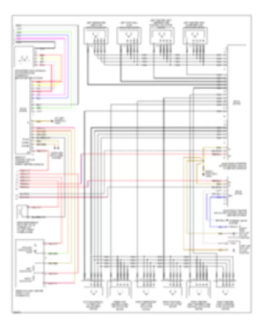
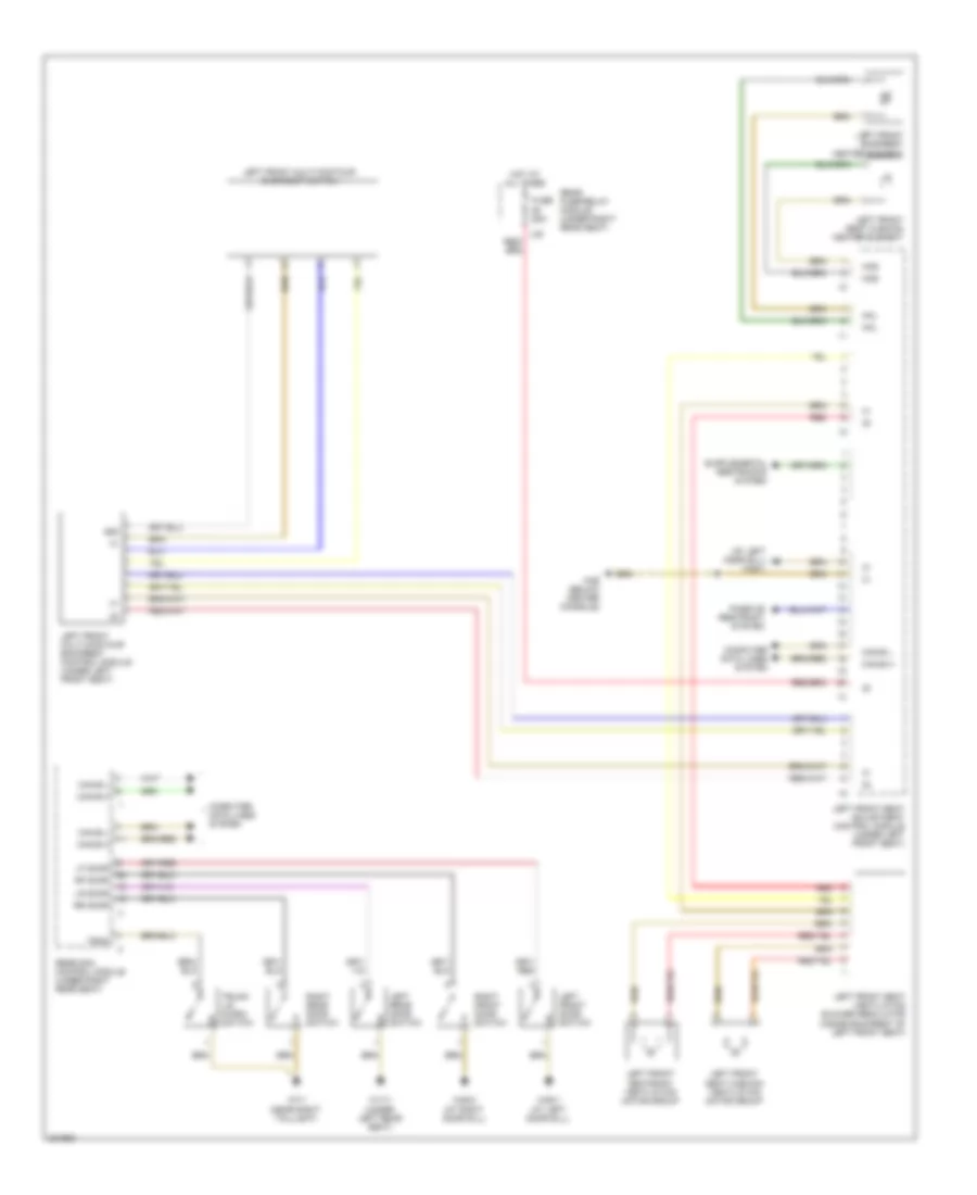
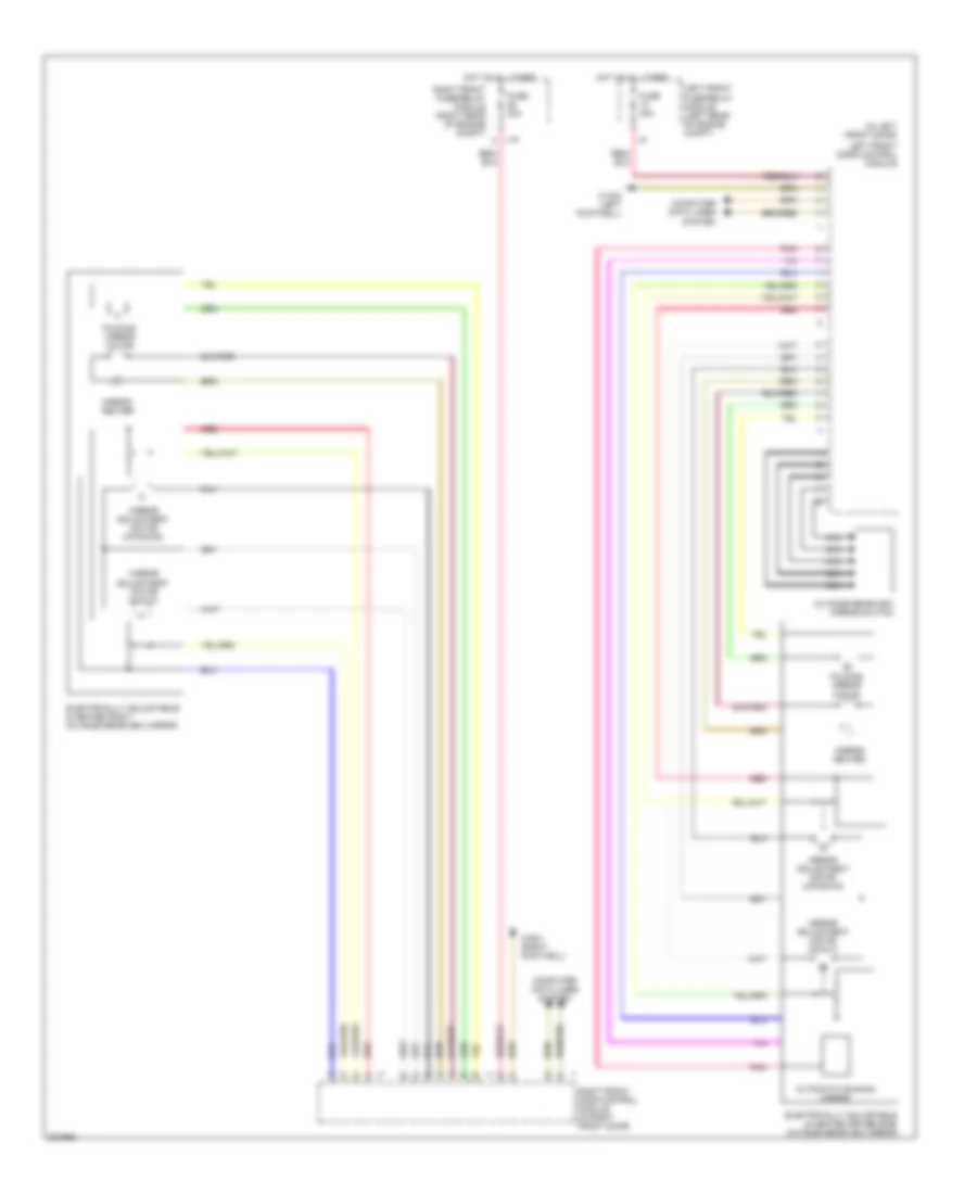
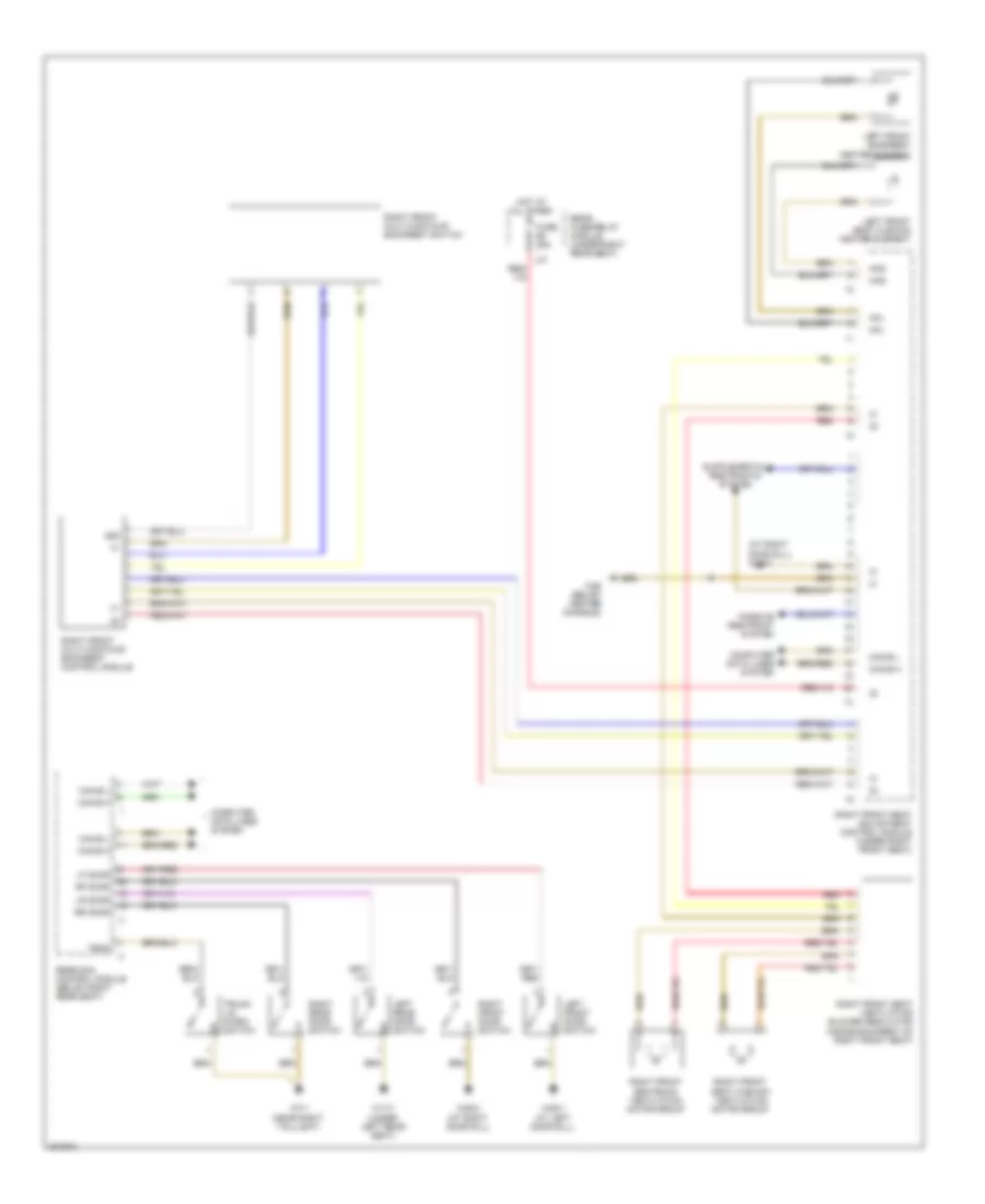
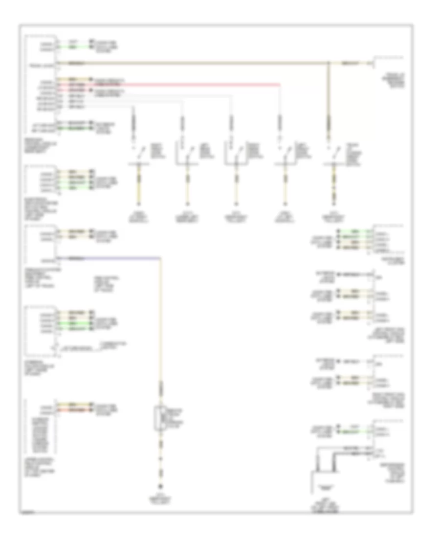
AIR CONDITIONING Automatic A/C Wiring Diagram (1 of 2) for Mercedes-Benz S500 2005 List of elements for Automatic A/C Wiring Diagram (1 of 2) for Mercedes-Benz S500 2005: 57 (2003) (right foot- well) w36/2 +12v A/c system blower unit Aac multifunction sensor (right rear of eng compt) Aac pushbutton control module (front center console) Aac sun sensor Blower motor Blower regulator Can-b h Can-b l Computer data lines system Coolant circulation pump Engine control module (me-sfi) (right rear of eng compt) Engine/climate control electric cooling fan (front center of engine) Evaporator temperature sensor Fuse 10a Fuse 150a Fuse 15a Fuse 20a Fuse 23 10a (2003) Fuse 60a Fuse 82 10a (2003-6) Hot at all time Hot at all times Hot in on or start Hot w/ engine electronic/ chassis relay L12 L26 L39 Left duovalve Left front fuse/relay module (2003) (left rear of engine compt) cockpit fuse box (2004-5) (right side of dash) Left front sam control module (in fuse/relay box, left side) Left heater core temperature sensor Left rear heater core temperature sensor (w/rear a/c) Mr1 Mr2 Nca Rear a/c electronic blower regulator (w/rear a/c) Rear blower motor (w/rear a/c) Rear evaporator temperature sensor (w/rear a/c) Rear fuse/ relay module (under right rear seat) Red Refrig temp sens gnd Refrig temp sens sig Refrigerant temperature sensor (left front of eng compt) Right duovalve Right front fuse/ relay module (right rear of engine compt) Right front sam control module (in fuse relay box, right side) Right fuse/ front relay module (left rear of engine compt) Right heater core temperature sensor Right rear heater core temperature sensor (w/rear a/c) Solid state Terminal block & fuse block (circuit 30 & 61) W2 (right side of eng compt) W28/1 (at left door sill) W3/7 (right front wheelhousing) Automatic A/C Wiring Diagram (2 of 2) for Mercedes-Benz S500 2005 List of elements for Automatic A/C Wiring Diagram (2 of 2) for Mercedes-Benz S500 2005: 32 (at left door sill) w28/1 (right footwell) w36/2 58d Active charcoal filter flap adjustment motor Air distribution (up/down) actuator motor (w/rear a/c) (behind center of dash) Can-bh Can-bl Computer data lines system Coolant circulation pump Electronic center air outlet control module (center of dash) Electronic stepper motor control module (in center console) Fresh air/ recirculated air actuator motor Interior lights system Left air outlet illum- ination Left center vent diverter flap actuator motor Left center vent temperature control actuator motor Left defroster vent flap actuator motor Left duovalve Left footwell flap actuator motor Nca Pnk R134a Rear a/c control module (w/rear a/c) (front center console) Rear refrigerant shut-off valve (w/rear a/c) (at left front wheelhouse) Red Right air outlet illum- ination Right center vent diverter flap actuator motor Right center vent temperature control actuator motor Right defroster vent flap actuator motor Right duovalve Right footwell flap actuator motor Solid state
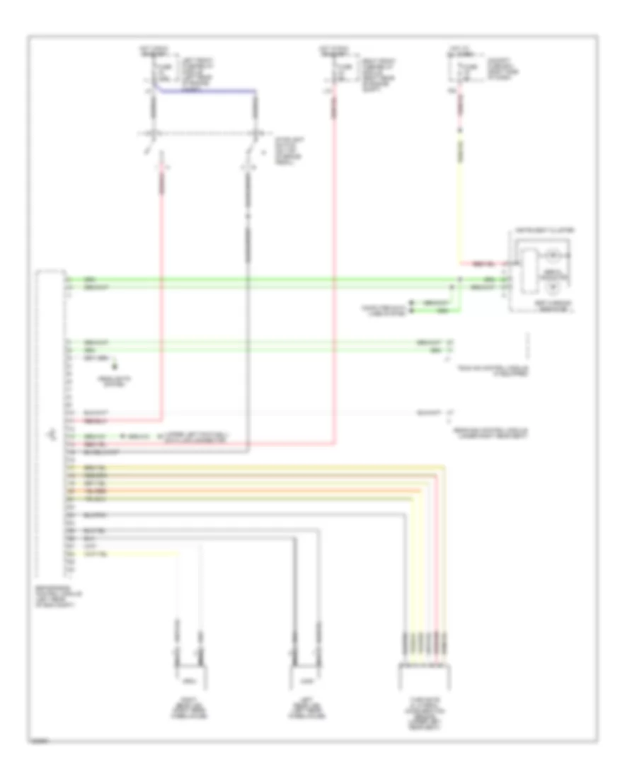
ANTI-LOCK BRAKES Anti-lock Brakes Wiring Diagram (1 of 2) for Mercedes-Benz S500 2005 List of elements for Anti-lock Brakes Wiring Diagram (1 of 2) for Mercedes-Benz S500 2005: 33 Brake booster (bas) Esp brake pressure sensor (behind left headlamp) Esp/sps/bas control module (left rear of eng compt) Front axle switchover Front axle vacuum Fuse 150a Fuse 50a High pressure/ return pump High pressure/ return pump relay Hot at all times I3 red Left front fuse/relay module (left rear of engine compt) Left front hold Left front release Left front vss sensor (left front wheelhouse) Left rear hold Left rear release Nca Rear axle switchover Rear axle vacuum Red Release switch Right front hold Right front release Right front vss sensor (right front wheelhouse) Right rear hold Right rear release Solenoid valve Sps solenoid valve (on power steering pump) Terminal block & fuse box Traction system hydraulic unit Travel sensor W9 (at left headlight) Anti-lock Brakes Wiring Diagram (2 of 2) for Mercedes-Benz S500 2005 List of elements for Anti-lock Brakes Wiring Diagram (2 of 2) for Mercedes-Benz S500 2005: 22 (upper left footwell) data link connector Abs mil indicator Cockpit fuse box (right side of dash) Computer data lines system Esp warning indicator Esp/sps/bas control module (left rear of eng compt) Fuse 5a Fuse 7.5a Headlights system Hot at all times Hot in run or start Instrument cluster L15 Left front fuse/relay module (left rear of engine compt) Left rear vss (left rear wheelhouse) Nca Rear sam control module (under right rear seat) Right front fuse/relay module (right rear of engine compt) Right rear vss (right rear wheelhouse) Stoplight switch (on top of brake pedal) Tele aid control module (if equipped) Turn rate & lateral acceleration sensor (under left rear seat)
ANTI-THEFT Anti-theft Wiring Diagram for Mercedes-Benz S500 2005 List of elements for Anti-theft Wiring Diagram for Mercedes-Benz S500 2005: 46 87a Alarm siren (w/ auxiliary battery) (rear of left front wheelwell) Anti- tow relay Anti-tow Ata (edw) inclination sensor (beneath right rear seat) Ata hood switch (front center of eng compt) Can-b h Can-b l Computer data lines system Edw Electronic ignition-starter switch control module (left side of dash, integral with ignition switch) Engine control module (me-sfi) (right rear corner of engine compt) Fuse 5a Fuse 60a Hood Hot at all times Left front door control module (in door) Left front door switch Left front ir receiver (in handle) Left front sam control module (in left front fuse/relay box) Left rear door switch Lf door Lr door Overhead control panel control module (above center rearview mirror) Rear fuse/ relay module (under right rear seat) Rear sam control module (below right rear seat) Red Rf door Right front door control module (in door) Right front door switch Right front ir receiver (in handle) Right front sam control module (in right front fuse/relay box) Right rear door switch Rr door Terminal block & fuse box Trnk Trunk lid micro- switch Ts/ims/ata function indicator switch Ultrasonic echolot sensor Upper control field control module (top center of dash) W15/2 (left footwell) W17/1 (under left rear seat) W2 (right side of eng compt) W28/1 (at left door sill) W28/2 (at right door sill) W7/1 (near right taillight)
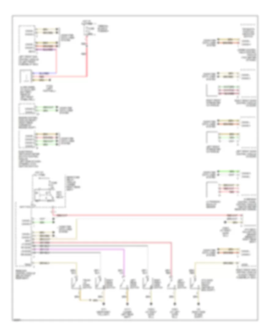
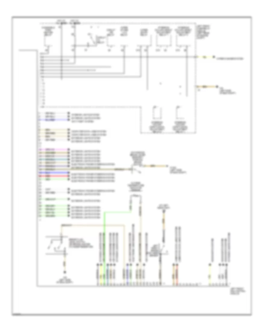
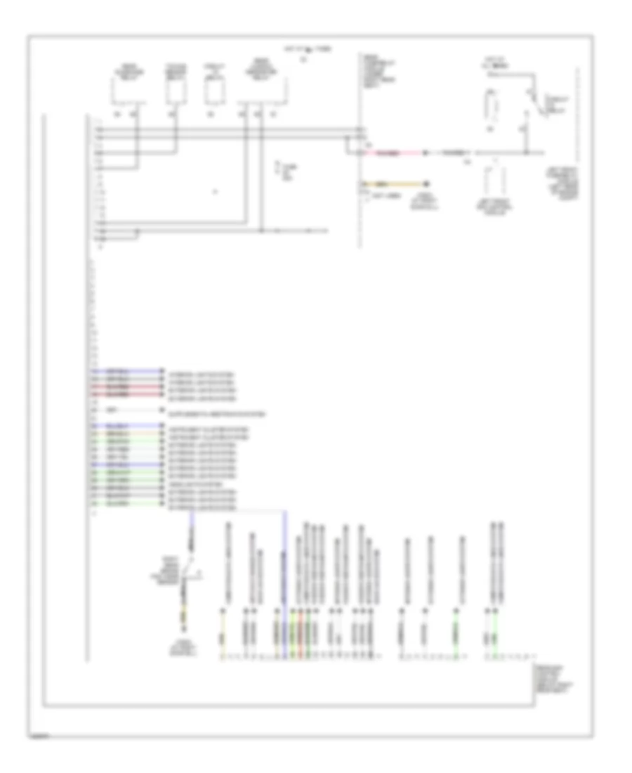
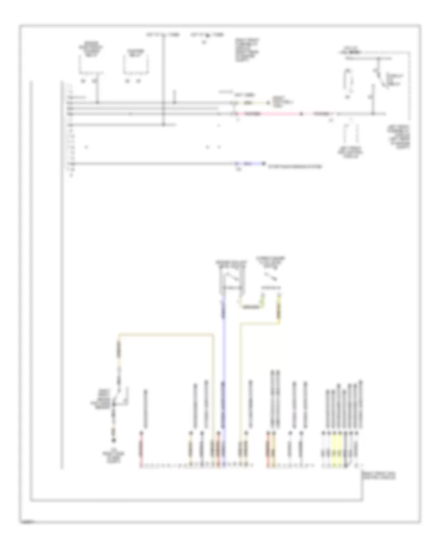
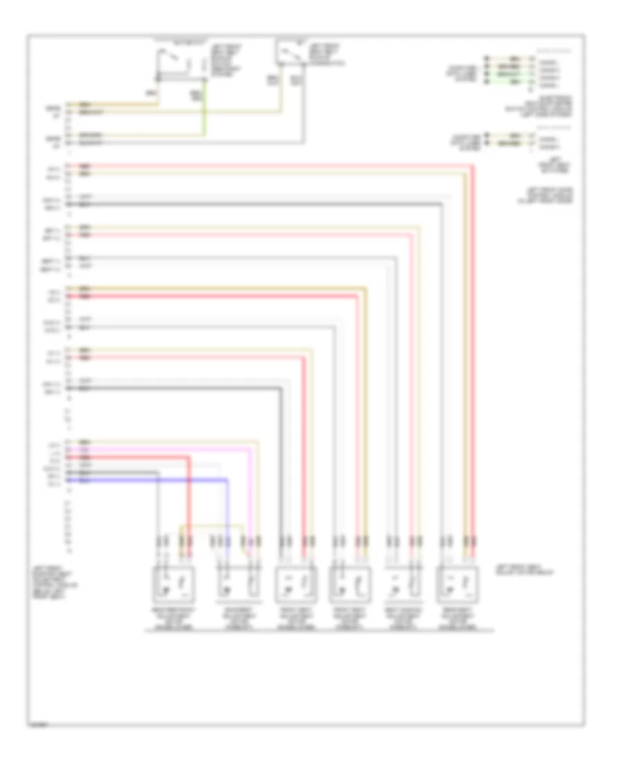
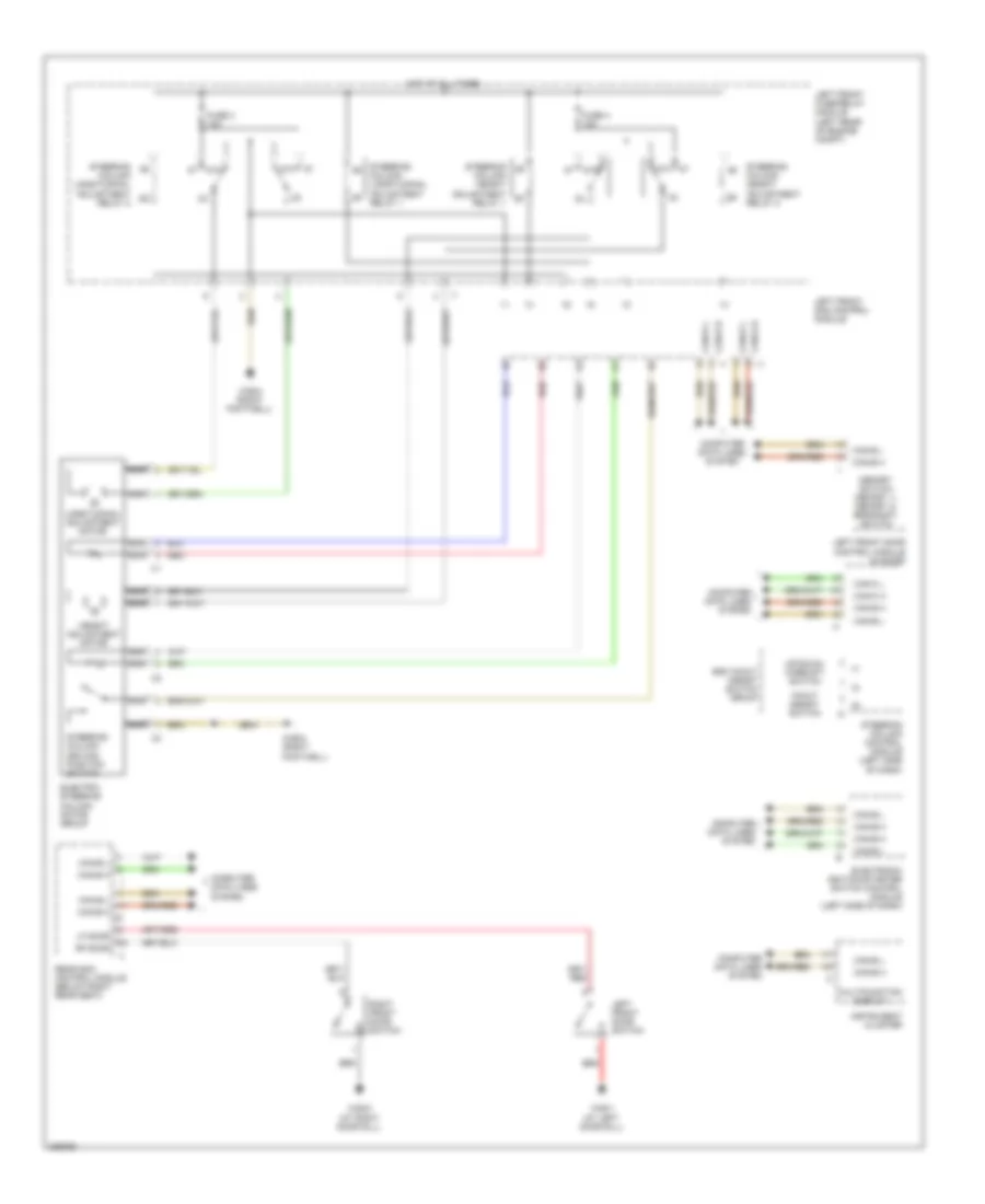
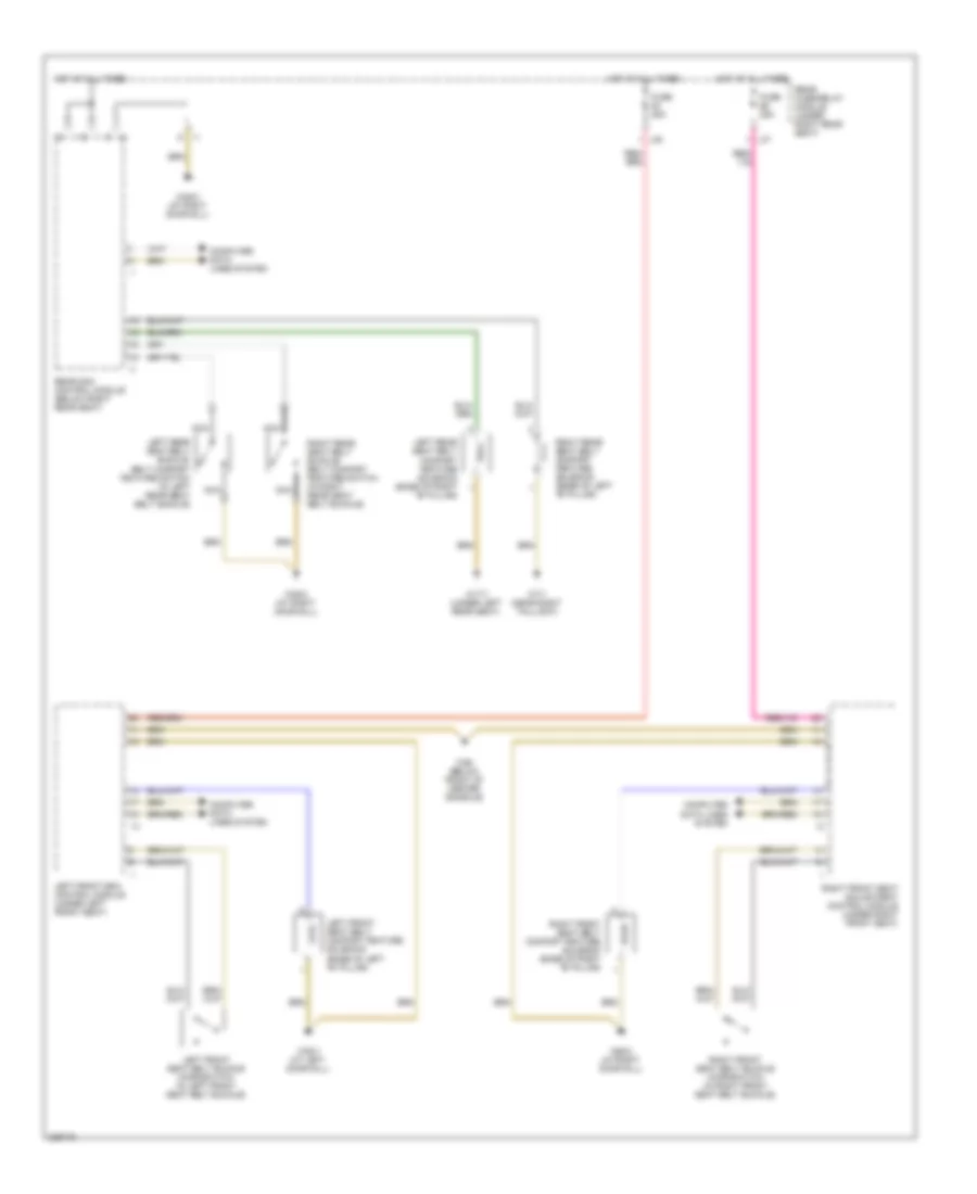
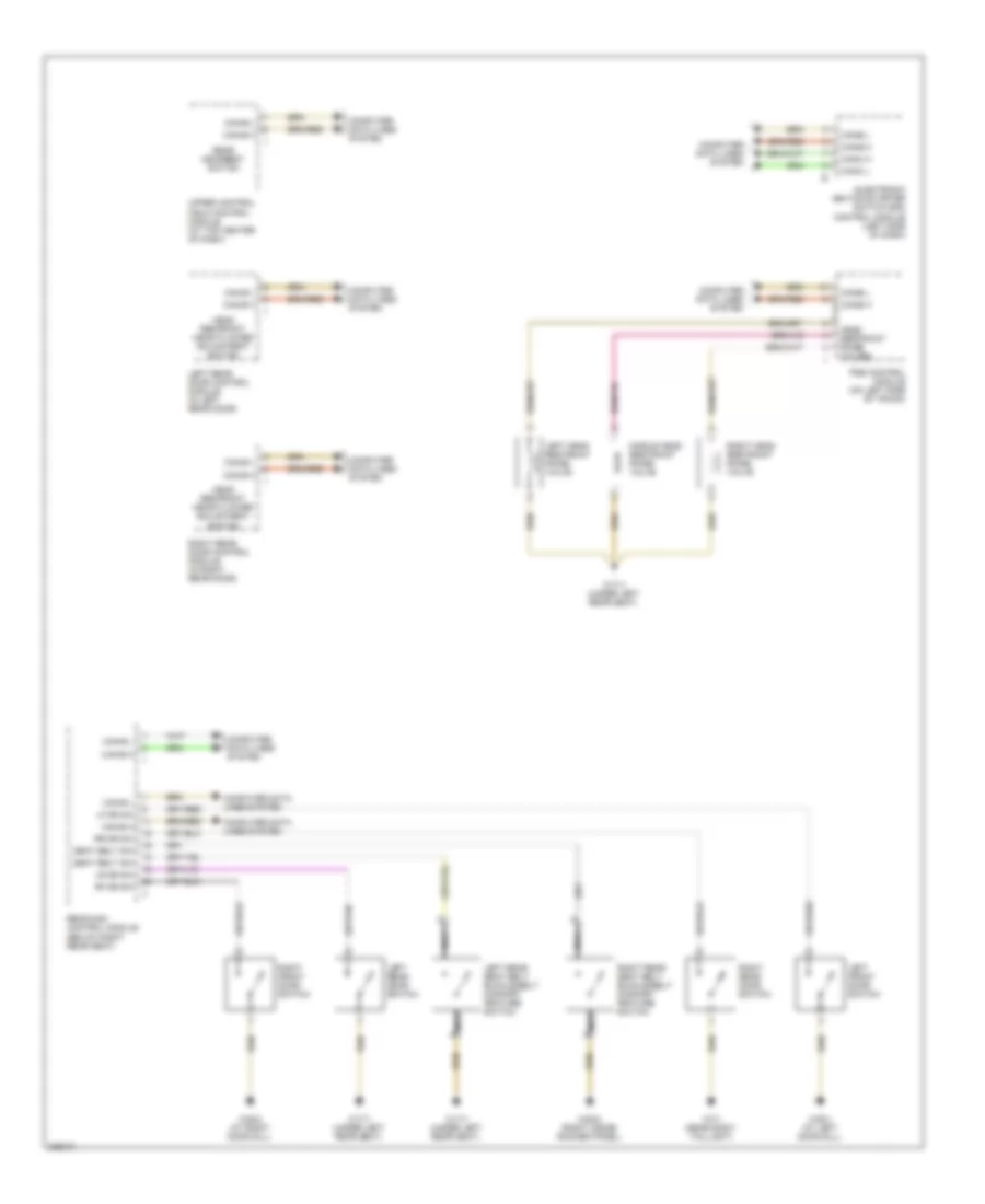
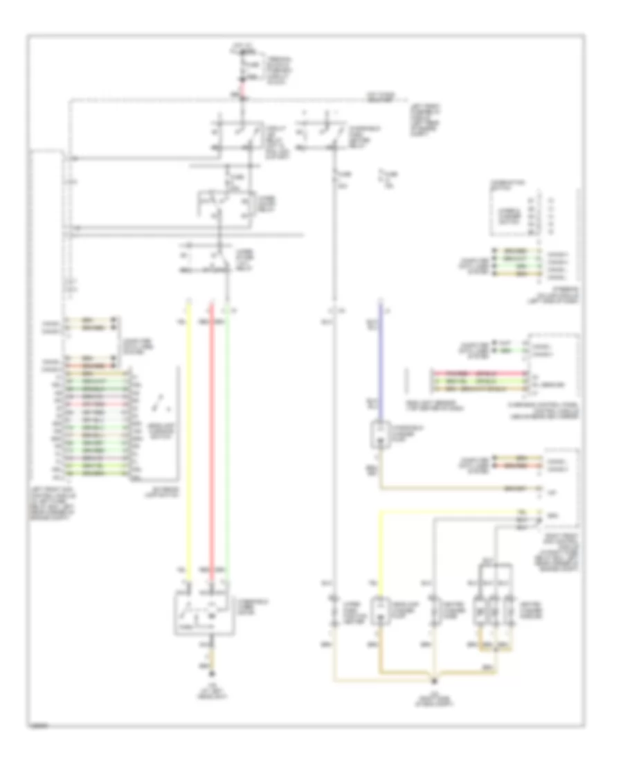
BODY CONTROL MODULES Left Front SAM Control Module Wiring Diagram for Mercedes-Benz S500 2005 List of elements for Left Front SAM Control Module Wiring Diagram for Mercedes-Benz S500 2005: 31 (at left headlight) (on parking brake lever bracket) parking brake switch 87a Air conditioning system Anti-theft system Brake fluid level switch (on brake master cylinder reservoir) Circuit 15r relay Circuit relay Computer data lines system Electronic power steering system Electronic suspension system Exterior lights system Headlights system Hot at all times Interior lights system Left front brake pad wear sensor Left front fuse/relay module (left rear of engine compt) Left front sam control module Nca Outside temperature indicator sensor Red Steering column height adjustment relay 1 Steering column height adjustment relay 2 Steering column longitudinal adjustment relay 1 Steering column longitudinal adjustment relay 2 W15/2 (left side of eng compt) W9 (left side of eng compt) Windshield park heater relay Wiper on/off relay Wiper stage 1 & 2 relay Wiper/washer system Rear SAM Control Module Wiring Diagram for Mercedes-Benz S500 2005 List of elements for Rear SAM Control Module Wiring Diagram for Mercedes-Benz S500 2005: 24 (not used) Anti-lock brakes system Anti-theft system Circuit relay Computer data lines system Door locks system Exterior lights system Fuse 50a Headlights system Hot at all times Instrument cluster system Interior lights system Left front fuse/relay module (left rear of engine compt) Left front sam control module Nca Passive restraints system Pnk/red Rear fuse/relay module (under right rear seat) Rear sam control module (below right rear seat) Rear sunshade relay Rear window defroster relay Right rear brake pad wear sensor Towing sensor relay W28/2 (at right door sill) Right Front SAM Control Module Wiring Diagram for Mercedes-Benz S500 2005 List of elements for Right Front SAM Control Module Wiring Diagram for Mercedes-Benz S500 2005: 23 (not used) (right footwell) w36/1 Air conditioning system Circuit relay Computer data lines system Engine coolant level switch Engine electronic/ chassis relay Exterior lights system Fanfare relay Headlights system Hot at all times Interior lights system Left front fuse/relay module (left rear of engine compt) Left front sam control module Nca Pnk/red Right front brake pad wear sensor Right front fuse/relay module (right rear of engine compt) Right front sam control module Starting/charging system W2 (right side of eng compt) Wiper/washer fluid level switch Wiper/washer system
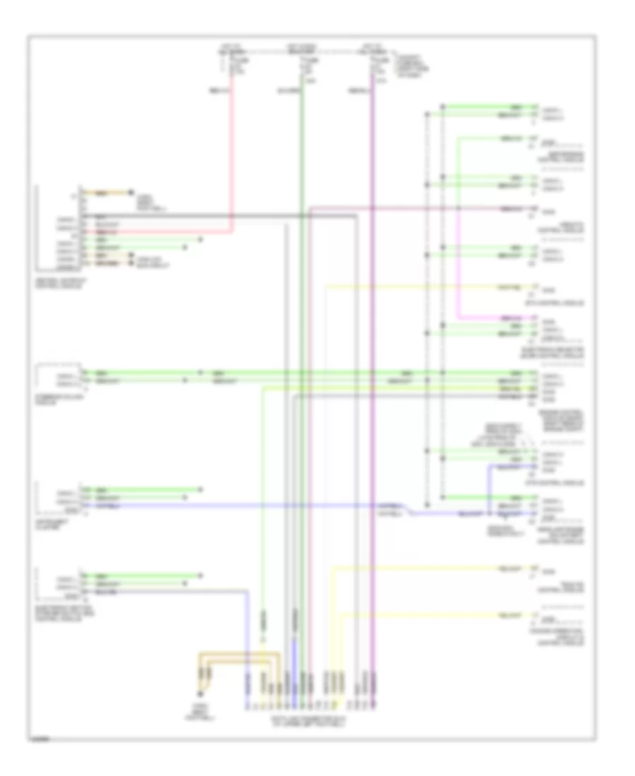
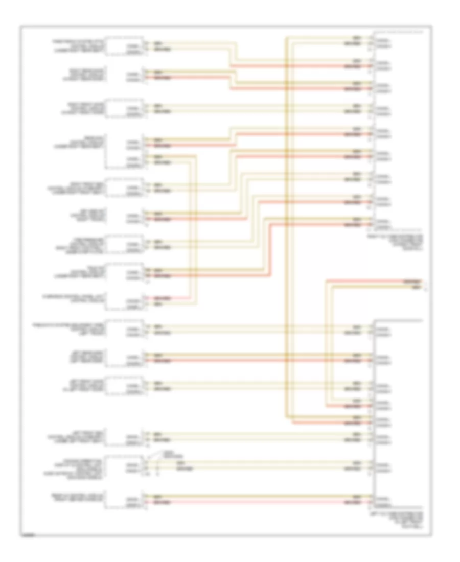
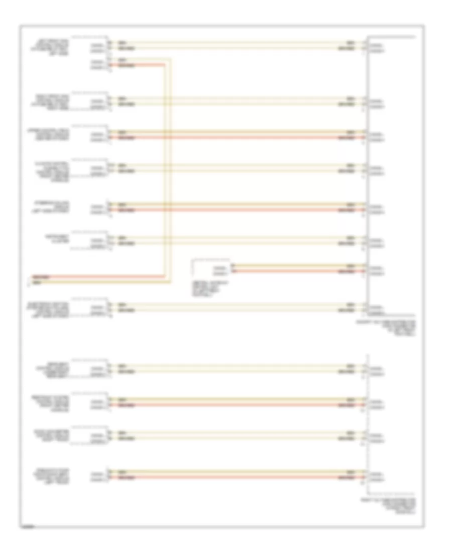
COMPUTER DATA LINES Data Link Connector Wiring Diagram for Mercedes-Benz S500 2005 List of elements for Data Link Connector Wiring Diagram for Mercedes-Benz S500 2005: 33 (2003 & early prod of 2004) (2003-2004 models only) (late prod of 2004, 2005 & 2006) 81a 84a Airmatic control module Can-b h Can-b l Can-c h Can-c l Can-d h Can-d l Central gateway control module Cockpit fuse box (right side of dash) Comand operating, display & control module Data link connector (dlc) (at upper left footwell) Diag Dtr control module Electronic ignition- starter switch (eis) control module Electronic selector lever control module Engine control module (me-sfi) (right rear of engine compt) Esp/sps/bas control module Etc control module Fuse 10a Fuse 5a Headlamp range adjustment control module High/low bus circuit Hot at all times Hot in run or start Instrument cluster Steering column module Tele aid control module W36/2 (right footwell) High/Low Bus Wiring Diagram (1 of 2) for Mercedes-Benz S500 2005 List of elements for High/Low Bus Wiring Diagram (1 of 2) for Mercedes-Benz S500 2005: 20 (2003) (2004-2006) Can-b h Can-b l Comand operating, display & control unit (2003 models) audio gateway control unit (2004-2006 models) Keyless go control module (right trunk) Left front door control module (in left front door) Left front esa control module (w/memory) (under left front seat) Left rear door control module (left rear door) Left voltage distributor (can) connector (in left front footwell) Overhead control panel unit control module Parktronic system (pts) control module (under right rear seat) Pneumatic system equipment (pse) control module (left trunk) Rear a/c control module (front center console) Rear sam control module (under right rear seat) Right front door control module (in right front door) Right front esa control module (w/memory) (under right front seat) Right rear door control module (in right rear door) Right voltage distributor (can) connector (in right front door sill) Tele aid control module (under right rear seat) Tire pressure control module (right front footwell, under step plate) High/Low Bus Wiring Diagram (2 of 2) for Mercedes-Benz S500 2005 List of elements for High/Low Bus Wiring Diagram (2 of 2) for Mercedes-Benz S500 2005: 16 Can-b h Can-b l Central gateway control unit (in left front footwell) Climate control pushbutton control module (front center console) Cockpit voltage distributor (can) connector (in left front footwell) Dc/dc converter control module (right trunk) Electronic ignition- starter switch (eis) control module (left side of dash) Instrument cluster Left front sam control module (in fuse relay box, left side) Pneumatic pump for dynamic seat control module (left trunk) Rear seat control module (under right rear seat) Restraint system control module (front center console) Right front sam control module (in fuse relay box, right side) Right voltage distributor (can) connector (in right front door sill) Steering column module (left side of dash) Upper control field control module (center of dash)
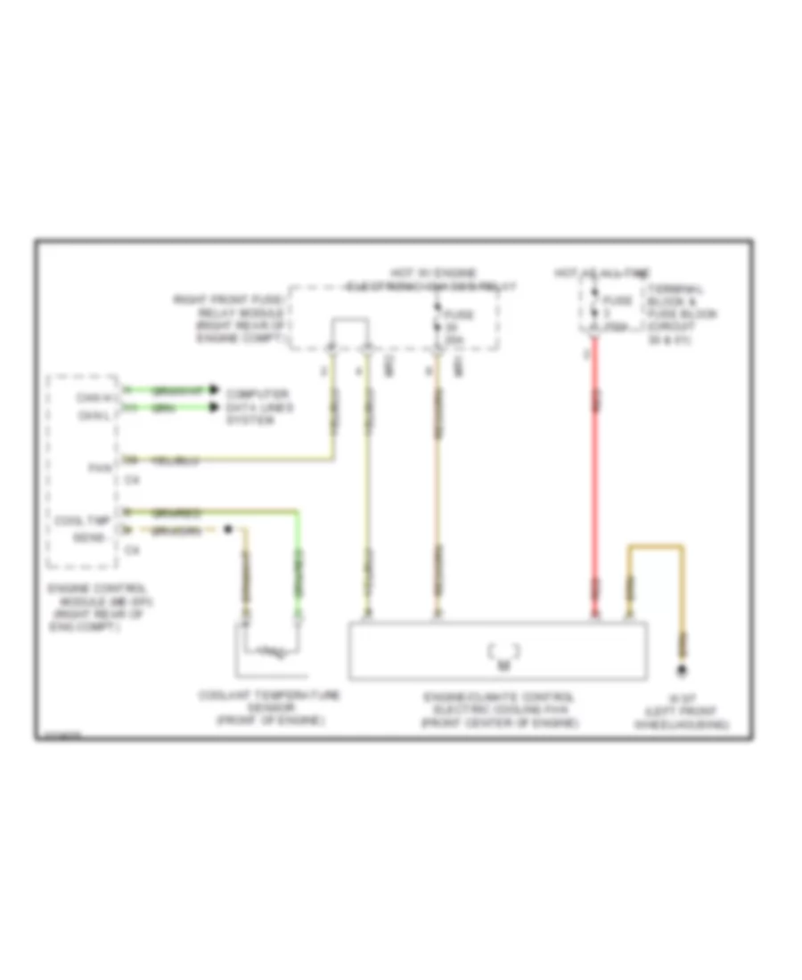
COOLING FAN Cooling Fan Wiring Diagram for Mercedes-Benz S500 2005 List of elements for Cooling Fan Wiring Diagram for Mercedes-Benz S500 2005: 21 (right rear of Can h Can l Computer data lines system Cool tmp Coolant temperature sensor (front of engine) Eng compt) Engine control module (me-sfi) Engine/climate control electric cooling fan (front center of engine) Fan Fuse 150a Fuse 20a Hot at all time Hot w/ engine electronic/ chassis relay Mr1 Mr2 Red Right front fuse/ relay module (right rear of engine compt) Sens - Terminal block & fuse block (circuit 30 & 61) W3/7 (left front wheelhousing)
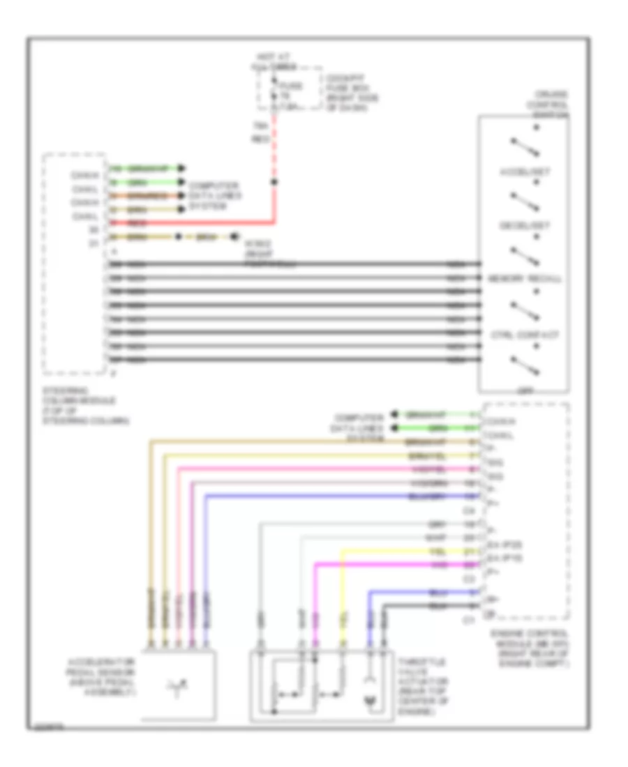
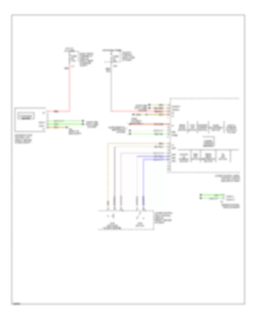
CRUISE CONTROL Cruise Control Wiring Diagram for Mercedes-Benz S500 2005 List of elements for Cruise Control Wiring Diagram for Mercedes-Benz S500 2005: 23 78a Accel/set Accelerator pedal sensor (above pedal assembly) Can h Can l Cockpit fuse box (right side of dash) Computer data lines system Cruise control switch Ctrl contact Decel/set Ea ip1s Ea ip2s Engine control module (me-sfi) (right rear of engine compt) Fuse 7.5a Hot at all times Memory recall Nca Off Red Sig Steering column module (top of steering column) Throttle valve actuator (rear top center of engine) W36/2 (right footwell) Electronic Accelerator/Cruise/Idle Speed Control Wiring Diagram for Mercedes-Benz S500 2005 List of elements for Electronic Accelerator/Cruise/Idle Speed Control Wiring Diagram for Mercedes-Benz S500 2005: 37 58d 80a Akse Art Can h Can l Can-b h Can-b l Can-c h Can-c l Cockpit fuse box (right side of dash) Comfort & sport switch Computer data lines system Distronic (dtr) control unit (front center of eng compt) Dtr distance potentiometer Dtr radar sensor Dtr switch Engine control module (me-sfi) Esp off switch Fuse 10a Fuse 7.5a Hazard warning switch Hot at all times L17 Level adjustment switch Lock cl interior switch & ata ind Lower control field control module (front center of dash) Lower control panel control module (center of dash) Pts off switch Rear blind switch Rear head restraints switch Red Right front fuse/relay module (right rear of engine compt) Ts off switch Unlock cl internal switch W2 (right of eng compt) W36/2 (at right footwell)
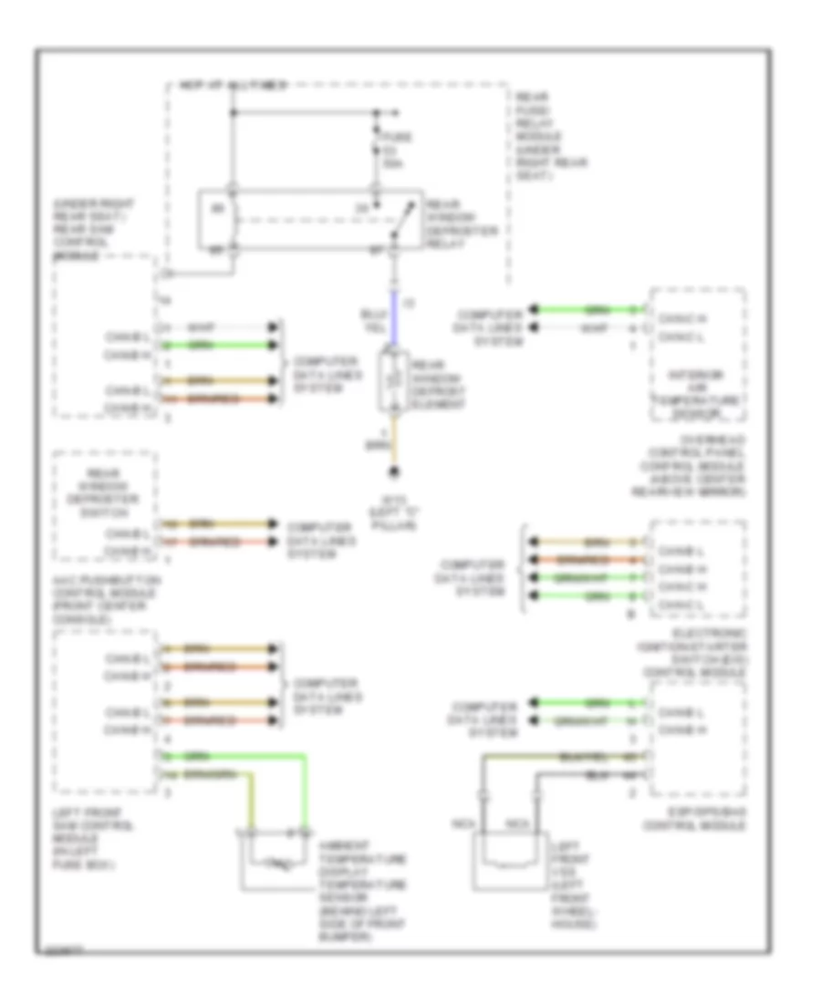
DEFOGGERS Defoggers Wiring Diagram for Mercedes-Benz S500 2005 List of elements for Defoggers Wiring Diagram for Mercedes-Benz S500 2005: 22 (under right rear seat) rear sam control module Aac pushbutton control module (front center console) Ambient temperature display temperature sensor (behind left side of front bumper) Can-b h Can-b l Can-c h Can-c l Computer data lines system Electronic ignition-starter switch (eis) control module Esp/sps/bas control module Fuse 50a Hot at all times Interior air temperature sensor Left front sam control module (in left fuse box) Left front vss (left front wheel- house) Nca Overhead control panel control module (above center rearview mirror) Rear fuse/ relay module (under right rear seat) Rear window defrost element Rear window defroster relay Rear window defroster switch W13 (left "c" pillar)
ELECTRONIC SUSPENSION Electronic Suspension Wiring Diagram for Mercedes-Benz S500 2005 List of elements for Electronic Suspension Wiring Diagram for Mercedes-Benz S500 2005: 91 (behind right head- light (in left front fuse box) left front sam control module (left side of eng compt) (on shock tower) front body lateral acceleration sensors (under right front of vehicle) Ahrm Ahrs Ahrv Air compressor relay Air-matic compressor unit (under right front of vehicle) Air-matic pressure sensor (right front wheelhouse) Air-matic w/ ads control module (in left front fuse/relay box) Avlm Avls Avlv Avrm Avrs Avrv Can hi Can lo Central reservoir charging valve Computer data lines system Datalink connector (at upper left footwell) Diag Fuse 150a Fuse 30a Fuse 40a Fuse 5a Hal 1 Hal 2 Hal v Har 1 Har 2 Har v Hot at all times Hot in run or start L25 Left Left front Left front axle damper valve assembly (at left front wheelhouse) Left front fuse/relay module (left rear of engine compt) Left front level sensor (left front wheel- house) Left rear Left rear axle damper valve unit (left rear wheelhouse) Level regulating valve assembly Leveling valves Mr1 Nca Nhl Nhr Nhrm Nhrs 1 Nhrs 2 Nhrv Nsp Nvl Nvlm Nvls 1 Nvls 2 Nvlv Nvr Nvrm Nvrs 1 Nvrs 2 Nvrv Rear axle level sensor (upper rear center of vehicle) Red Right Right front Right front axle damper valve assembly (at right front wheelhouse) Right front fuse/relay module (right rear of engine compt) Right front level sensor (right front wheel- house) Right rear Right rear axle damper valve unit (right rear wheelhouse) Right rear body lateral acceleration sensor (right side of trunk) Rkps Rkpv Samf Spm Sps Spv Terminal block & fuse block Unit) w3/6 Val 1 Val 2 Valv Var 1 Var 2 Varv Vkps Vkpv
ENGINE PERFORMANCE
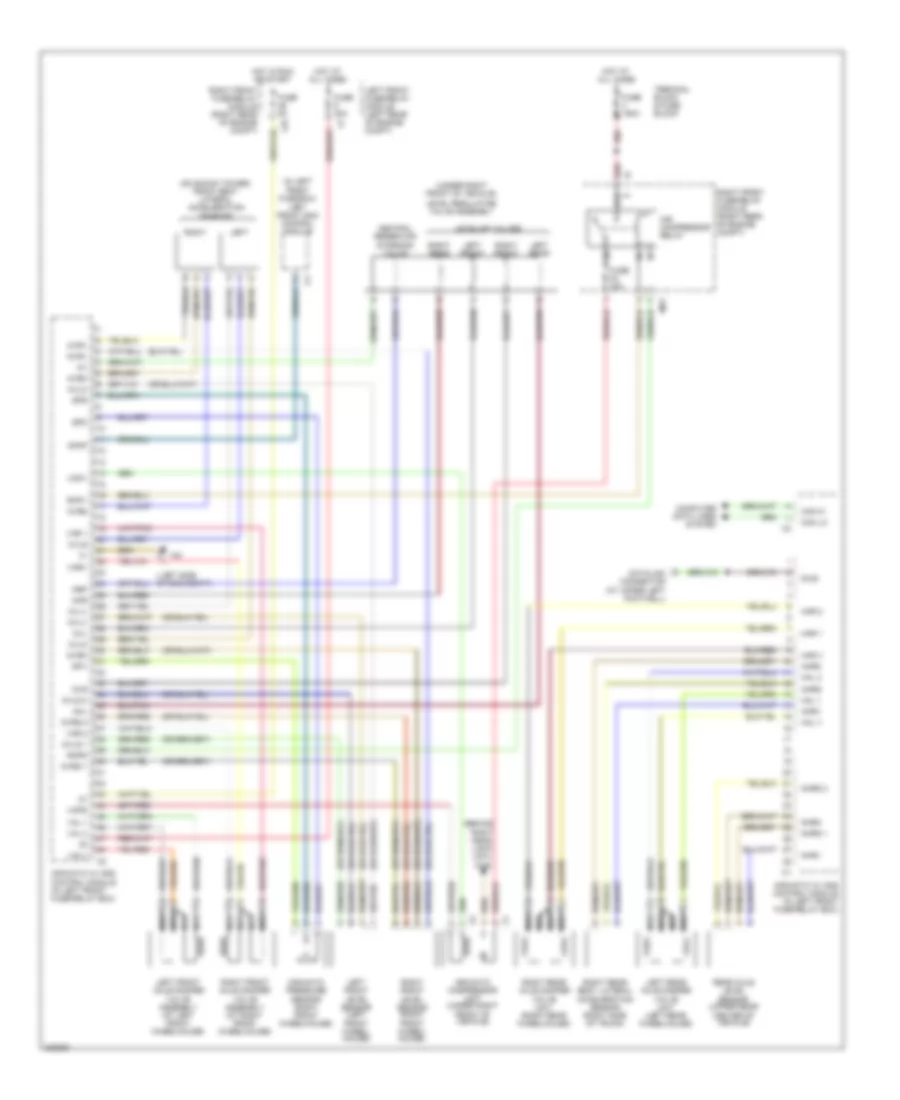
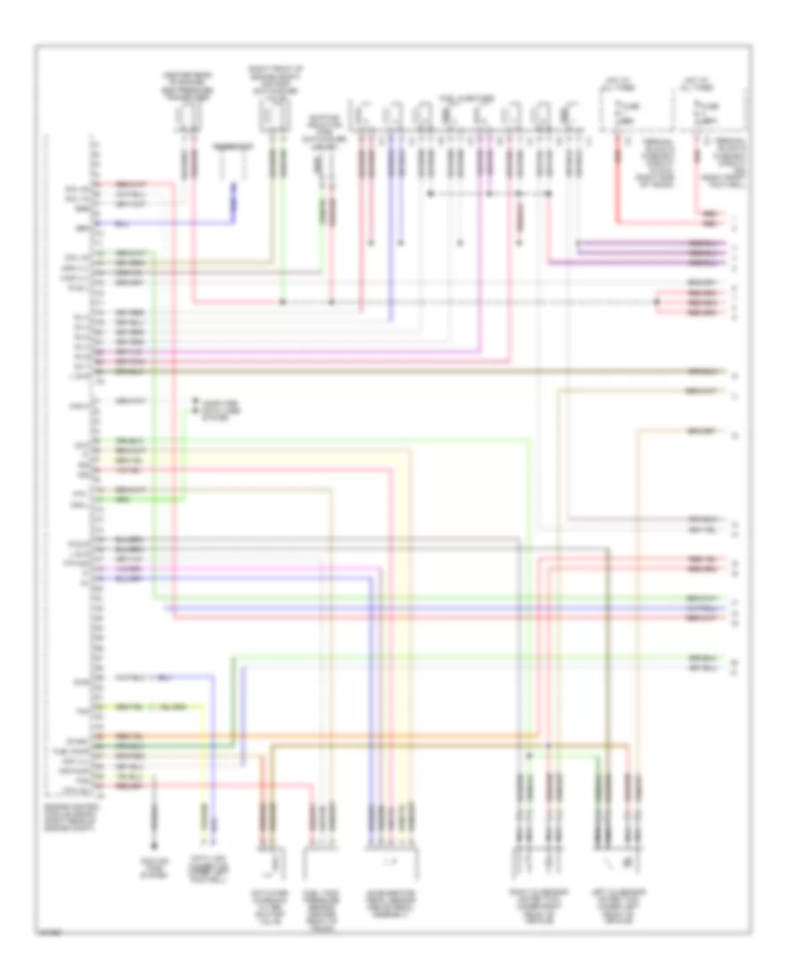
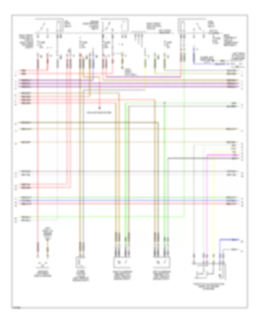
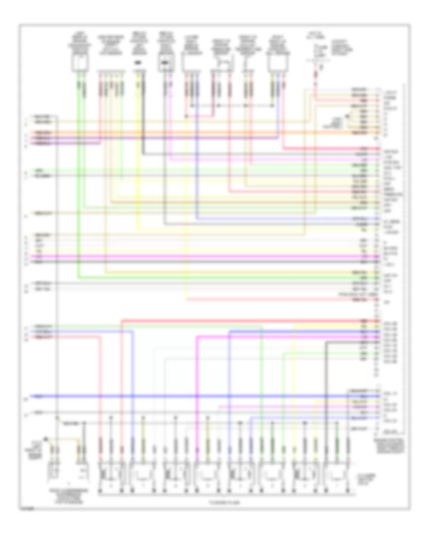
5.0L 5.0L, Engine Performance Wiring Diagram (1 of 3) for Mercedes-Benz S500 2005 List of elements for 5.0L, Engine Performance Wiring Diagram (1 of 3) for Mercedes-Benz S500 2005: 51 (center rear of engine) egr pressure transducer (right front of engine compt) air pump switchover valve Accelerator pedal sensor (above pedal assembly) Acf vlv Activated charcoal filter shutoff valve Air pump Aps vlv Can h Can l Coil 3a Coil 7a Coil 8a Computer data lines system Cooling fans system Data link connector (upper left footwell) Diag Egr Engine control module (me-sfi) (right rear of engine compt) Fan Ftp +5v Ftp - Ftp sig Fuel injectors Fuel pump Fuel tank pressure sensor (center front of trunk) Fuse 150a Fuse 60a Gen Generator Hot at all times Inj 2 Inj 3 Inj 4 Inj 6 Inj 7 Inj 8 L o2 s Left o2 sensor (after twc) (under left front of vehicle) Nca O2 d R o2 s R o2 u Red Right o2 sensor (after twc) (under right front of vehicle) Shifting induction pipe switchover valve Sig Start Terminal block & fuse box (circuit 30 & 61) (right side of trunk) Terminal block & fuse box (circuit 30z) (right front footwell) Tna Vims vlv 5.0L, Engine Performance Wiring Diagram (2 of 3) for Mercedes-Benz S500 2005 List of elements for 5.0L, Engine Performance Wiring Diagram (2 of 3) for Mercedes-Benz S500 2005: 27 (left front of engine compt) w11/3 (left rear of vehicle) fuel pump (under left rear seat) w17/1 Air pump (top front side of engine) Air pump relay Cooling fans system Engine electronics/ chassis relay Fuel pump relay Fuse 15a Fuse 20a Fuse 30a Fuse 40a Hot at all times Hot in run or start L27 Left o2 sensor (before twc) (left rear of engine compt) Mr1 Mr2 Nca Purge control valve (left rear of engine compt) Rear fuse/relay module (under right rear seat) Red Right front fuse/ relay module (right rear of engine compt) Right front sam control module Right o2 sensor (before twc) (right rear of engine compt) Throttle valve actuator (rear top center of engine) W36/1 (right footwell) 5.0L, Engine Performance Wiring Diagram (3 of 3) for Mercedes-Benz S500 2005 List of elements for 5.0L, Engine Performance Wiring Diagram (3 of 3) for Mercedes-Benz S500 2005: 62 (below intake manifold) left knock sensor (below intake manifold) right knock sensor (center rear of engine compt) hot film maf sensor (front of engine) (front of engine) coolant temperature sensor (left rear of engine) crankshaft position sensor (lower right side of engine) oil sensor (pins 29-38: not used) (right front of engine) camshaft hall sensor +5v 30z 78a Ckp Clear Cmp sig Cockpit fuse box (right side of dash) Coil 1a Coil 1b Coil 2a Coil 2b Coil 3b Coil 4a Coil 4b Coil 5a Coil 5b Coil 6a Coil 6b Coil 7b Coil 8b Cool tmp Cylinder ignition coils Ea ip1s Ea ip2s Engine control module (me-sfi) (right rear of engine compt) Fuse 7.5a Hot at all times Inj 1 Inj 5 L ks - L ks sig L o2 ht L o2 u Maf Maf +5v Maf - Maf sig O2 u Oil sens Pnk Press sig Pressure sensor Purge R ks - R ks sig R o2 ht R o2 u Radio interference suppression capacitors (top of engine) Red Sens - To spark plugs W11/3 (left front of engine compt) W36/1 (right footwell)
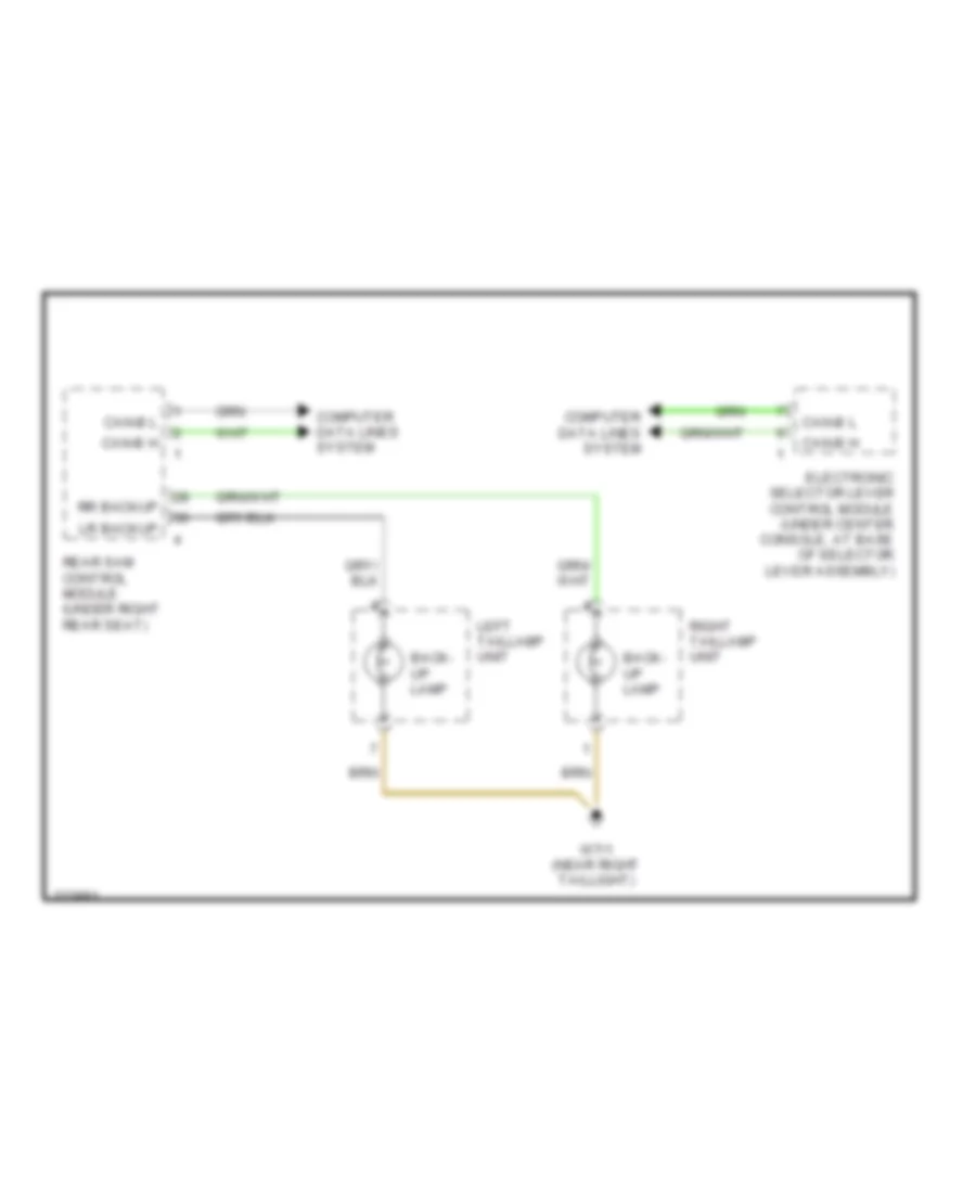
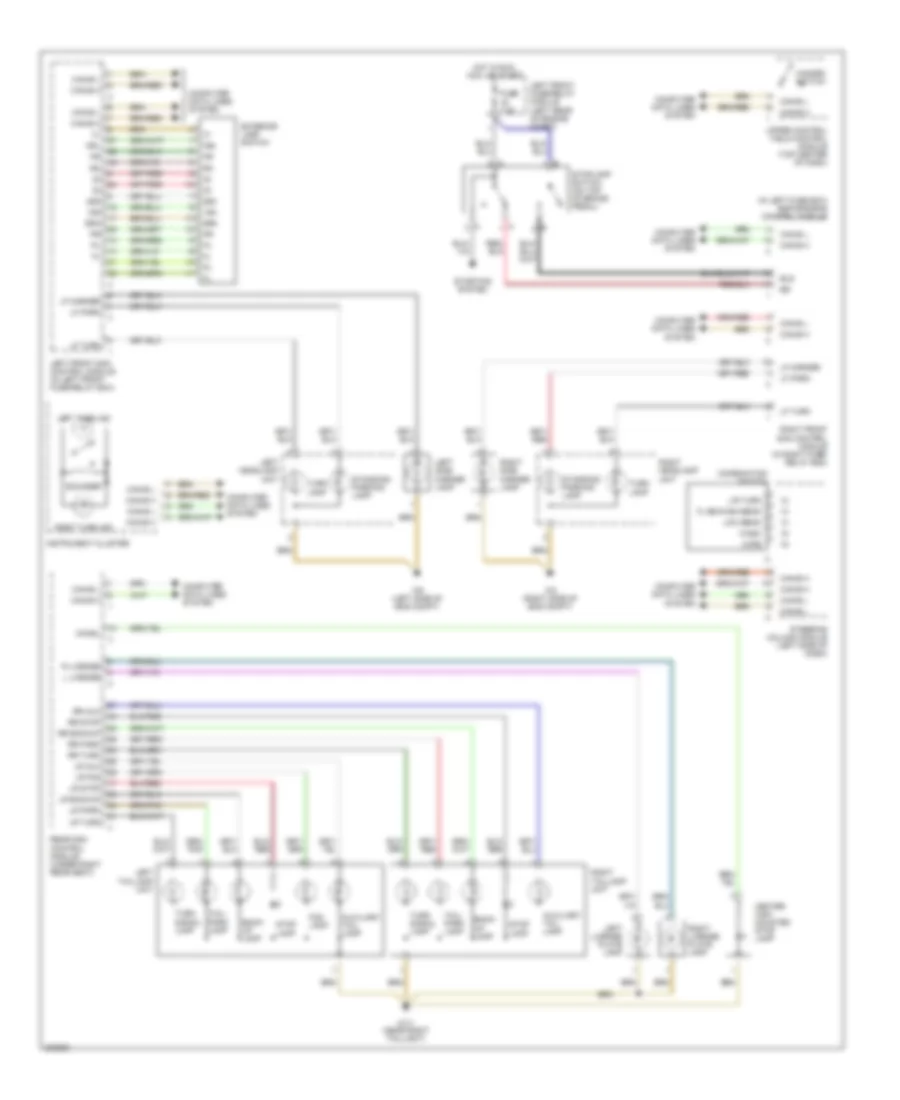
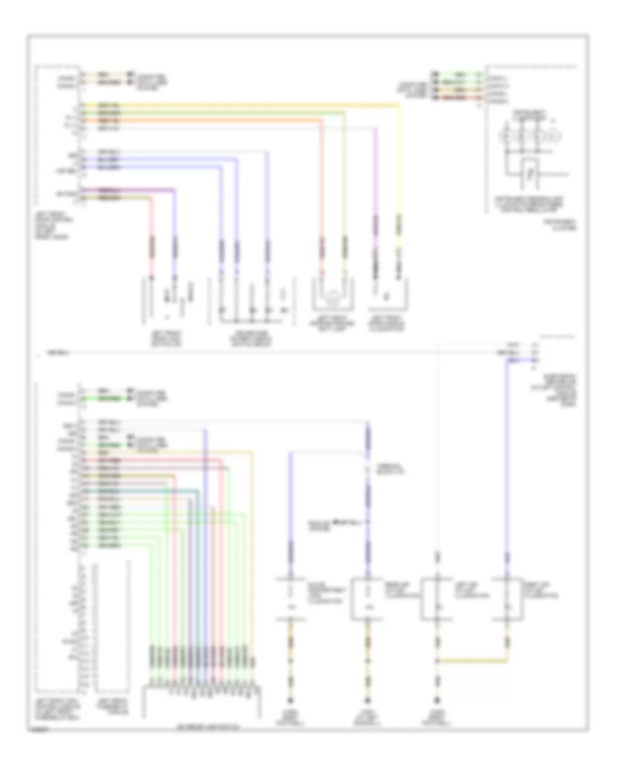
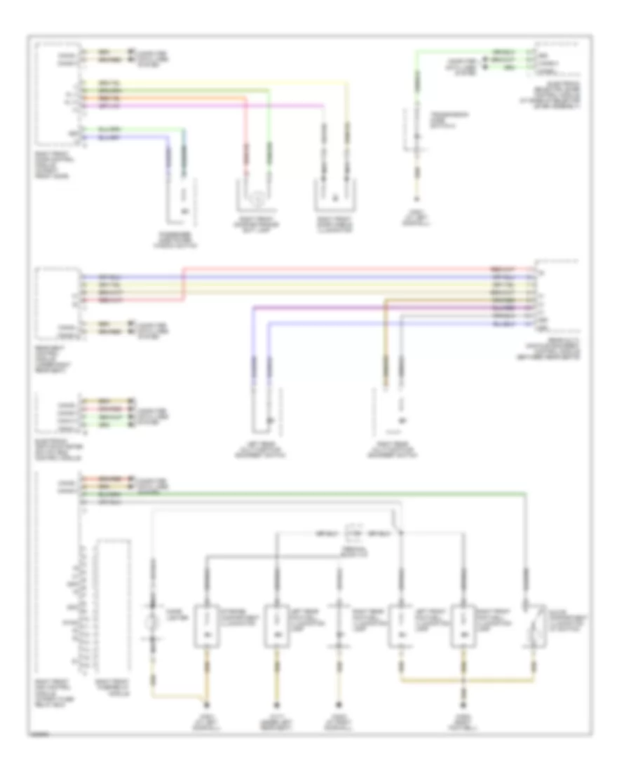
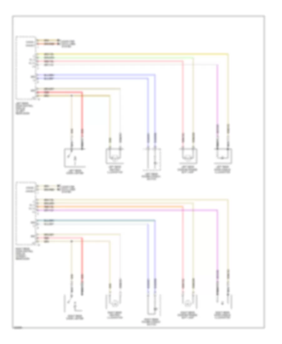
EXTERIOR LIGHTS Backup Lamps Wiring Diagram for Mercedes-Benz S500 2005 List of elements for Backup Lamps Wiring Diagram for Mercedes-Benz S500 2005: 11 Back- up lamp Can-b h Can-b l Computer data lines system Electronic selector lever control module (under center console, at base of selector lever assembly) Left taillamp unit Lr backup Rear sam control module (under right rear seat) Right taillamp unit Rr backup W7/1 (near right taillight) Exterior Lamps Wiring Diagram for Mercedes-Benz S500 2005 List of elements for Exterior Lamps Wiring Diagram for Mercedes-Benz S500 2005: 68 (in left fuse box) esp/sps/bas control module 15g 58d Auxiliary tail lamp Back- up lamp Bls Can-b h Can-b l Center high mounted stop lamp Chmsl Combination switch Computer data lines system Exterior lamp switch Flash/high beam Fog lamp Fuse 7.5a Hazard switch Hot in run, acc, or start Instrument cluster L license L/r turn Left front fuse/relay module (left rear of engine compt) Left front sam control module (in left front fuse/relay box) Left headlamp unit Left license plate lamp Left side marker lamp Left taillamp unit Left turn ind Lf marker Lf park Lf turn Low beam Lr aux Lr backup Lr fog Lr park Lr stop Lr turn Nsl R license Rear sam control module (under right rear seat) Right front sam control module (in right fuse/ relay box) Right headlamp unit Right license plate lamp Right side marker lamp Right taillamp unit Right turn ind Rr aux Rr backup Rr park Rr stop Rr turn Sounder Sra Standing/ parking lamp Starting system Steering column module (left side of dash) Stop lamp Stoplamp switch (on top of brake pedal) Tail/ park lamp Turn lamp Turn signal lamp Upper control field control module (top center of dash) W2 (right side of eng compt) W7/1 (near right taillight) W9 (left side of eng compt) Wash Wipe
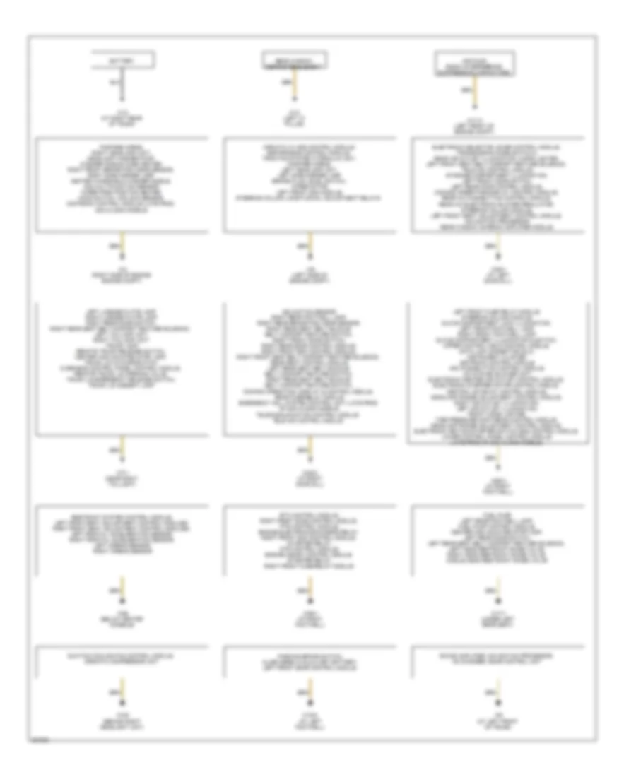
GROUND DISTRIBUTION Ground Distribution Wiring Diagram for Mercedes-Benz S500 2005 List of elements for Ground Distribution Wiring Diagram for Mercedes-Benz S500 2005: 31 Air pump, radio interference suppression capacitors Airmatic w/ ads control module, esp/sps/bas control module, traction system hydraulic unit, fanfare horns, left headlamp unit, left side marker lamp brake fluid level switch, wiper motor, left front sam module, steering column longitudinal adjustment relays Battery Electronic selector lever control module, transmission mode switch 2, rear air outlet illumination, cigar lighter, left front seat belt comfort feature solenoid, tele aid control module, storage compartment illumination, left front door switch, left rear door control module, comand operating/display control module, rear a/c pushbutton control module, rear a/c electronic blower regulator, steering column module, left front seat adjustment control module, navigation processor rear window antenna amplifier module Etc control module, right front door control module, pts control module, engine electronics/chassis relay, right front sam control module, starter relay, dtr control module, engine (me-sfi) control module, starter relay, right front fuse/relay module Fanfare horns, right headlamp unit, headlamp washer pump, washer nozzle hose heater, right front brake pad wear sensor, right side marker lamp, heated windshield washer nozzle, aac multifunction sensor, wiper park position heater, hood switch, aac sun sensor, distronic control module (late prod 2004 & 2005 models) Fuel pump, left rear footwell lamp, fuel pump control module, center high mounted stop lamp, left rear door switch, left rear seat belt comfort feature solenoid, left head restraint raise valve, right head restraint raise valve, middle head restraint raise valve Inclination sensor, right rear footwell lamp, right rear brake pad wear sensor, right rear seat belt buckle/ belt comfort feature switch, right front door switch, right rear door control module, right front esa control module, right front seat belt comfort feature solenoid, rear seat control module left rear seat belt buckle/ belt comfort feature switch, right rear seat belt buckle/ belt comfort feature switch, comand operating, display & control module, rear fuse/relay module emergency call system control unit (late prod of 2004 & 2005 models) Left front fuse relay module, steering column module, glove compartment lock illumination, left front footwell lamp, right front footwell lamp glove compartment illumination & switch, upper control field control module, data link connector (dlc), instrument cluster, distronic control module aac pushbutton control module, a/c system blower unit, electronic center air outlet control module, electronic stepper motor control module, central gateway control module, headlamp range adjustment control module, right air outlet illumination, left air outlet illumination, front cigar lighter, tire pressure monitoring control module, headlamp range adjustment control module, electronic ignition-starter switch (eis) control module lower control panel control module (late prod of 2004 & 2005 models), Left license plate lamp, right license plate lamp right rear door switch, right rear seat belt comfort feature solenoid, left taillamp unit, right taillamp unit, trunk lamp, remote trunk release switch, center high mounted stop lamp, trunk lid ca microswitch, overhead control panel control module, remote trunk lid opening valve, trunk lid emergency release switch, trunk lid ambient lamp Parking brake switch, alarm siren w/auxiliary battery, left front door control module Rear window defroster element Restraint system control module, left front seat adjustment control modules, right front seat adjustment control modules, left frontal acceleration sensor, right frontal acceleration sensor, left airbag sensor, right airbag sensor Sound amplifier, navigation processor, cd changer, sdar control unit Suction cooling fan control module, airmatic compressor unit Telecommunication control module tele aid control module W10 (at right rear of trunk) W11/3 (left front of engine compt) W13 (left "c" pillar) W15/2 (at left footwell) W17/1 (under left rear seat) W2 (right side of engine engine compt) W26 (below center console) W28/1 (at left door sill) W28/2 (at right door sill) W3/6 (behind right headlight unit) W36/1 (at right footwell) W36/2 (at right footwell) W6 (at left front of trunk) W7/1 (near right taillight) W9 (left side of engine compt)
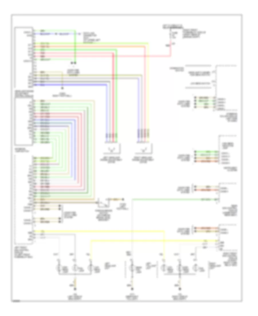
HEADLIGHTS Headlights Wiring Diagram for Mercedes-Benz S500 2005 List of elements for Headlights Wiring Diagram for Mercedes-Benz S500 2005: 49 15g 56a 56b 58d Can-b h Can-b l Can-c h Can-c l Combination switch Computer data lines system Data link connector (dlc) (at upper left footwell) Diag Exterior lamp switch Fog lamp Fsb Fuse 10a Headlamp flasher/ high beam switch Headlamp range adjustment control module High beam indicator lamp High beam lamp Hot w/ circuit 15 relay energized Instrument cluster L20 Left front sam control module (in left front fuse/relay box) Left headlamp range adjustment motor Left headlamp unit Left taillamp unit Low beam lamp Low beam switch Nsl Parking brake switch (on parking brake level bracket) Q11 Q12 Q21 Q22 Rear fog lamp Rear sam control module (under right rear seat) Red Right front fuse/relay module (right rear of engine compt) Right front sam control module (in right front fuse/ relay box) Right headlamp range adjustment motor Right headlamp unit Sra Steering column module (left side of dash) W15/2 (left footwell) W2 (right side of eng compt) W36/2 (right footwell) W7/1 (near right taillight) W9 (left side of eng compt)
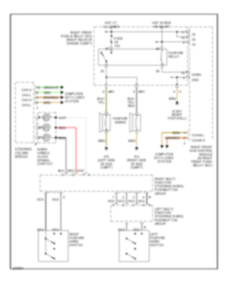
HORN Horn Wiring Diagram for Mercedes-Benz S500 2005 List of elements for Horn Wiring Diagram for Mercedes-Benz S500 2005: 26 Can h Can l Can-b h Can-b l Computer data lines system Fanfare horns Fanfare relay Fuse 15a Gnd Horn Horn/ airbag clock spring contact Hot at all times Hot in run or start Left fanfare horn switch Left multi- function steering wheel pushbutton group Mr1 Nca Red Right fanfare horn switch Right front fuse & relay box (right rear of engine compt) Right front sam control module (in right front fuse/ relay box) Right multi- function steering wheel pushbutton group Steering column module W2 (right side of eng compt) W36/1 (right footwell) W9 (left side of eng compt)
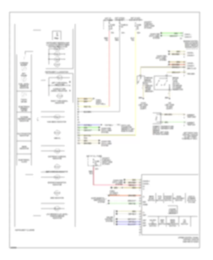
INSTRUMENT CLUSTER Instrument Cluster Wiring Diagram for Mercedes-Benz S500 2005 List of elements for Instrument Cluster Wiring Diagram for Mercedes-Benz S500 2005: 73 (in left front 58d 79a 80a 84a 85a Abs mil Akse Ambient temp gnd Ambient temp sig Ambient temperature display temperature sensor (behind left side of front bumper) Art Audible turn signal indicator Brake fluid level switch (on brake cylinder reservoir) Brk fluid Can-b h Can-b l Can-c h Can-c l Cockpit fuse box (right side of dash) Comfort & sport switch Computer Computer data lines system Cruise control system Data lines Data link connector (beneath left side of dash) Distronic warning indicator Ect gauge Electronic clock Electronic speedo- meter Engine control module (me-sfi) (right rear of engine compt) Engine diagnostics indicator Esp off switch Esp warning indicator Fuel level/ reserve indicator Fuse 10a Fuse 5a Fuse 84 5a Fuse/relay box) Gear indicator Hazard warning switch High beam indicator Hot at all times Hot in acc run or start Hot in run or start Instrument cluster Instrument illumination Instrument/searchlamp illumination brightness control regulator Left front sam control module Left turn signal indicator Level adjustment switch Lock cl interior switch & ata ind Low brake fluid level/ parking brake indicator Multifunction indicator Outside temperature indicator Parking brake switch (on parking brake lever bracket) Pnk Prk brk Pts off switch Rear blind switch Rear head restraints switch Right turn signal indicator Srs indicator System Tacho- meter Ts off switch Unlock cl internal switch Upper control panel control module (center of dash) W15/2 (left side of eng compt) W36/2 (at right footwell) W36/2 (right footwell) W9 (left side of eng compt) Warning buzzer
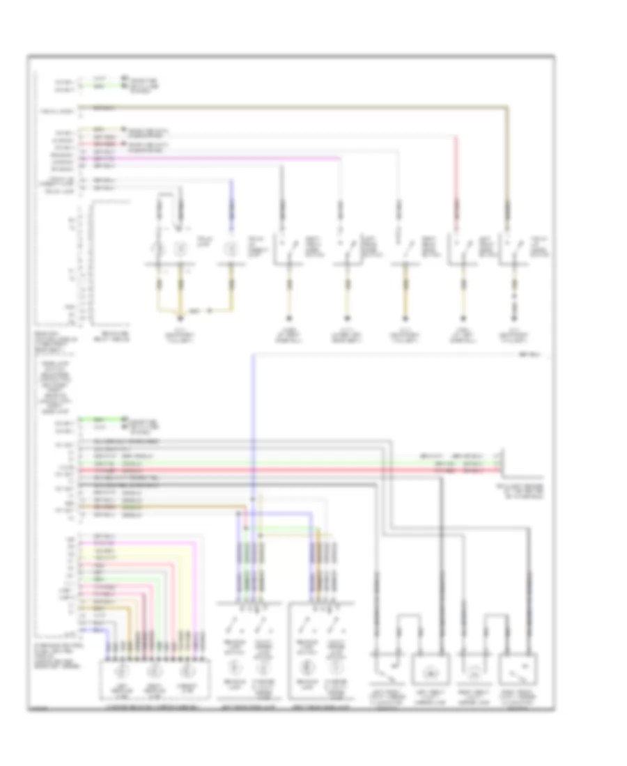
INTERIOR LIGHTS Interior Lights Wiring Diagram (1 of 4) for Mercedes-Benz S500 2005 List of elements for Interior Lights Wiring Diagram (1 of 4) for Mercedes-Benz S500 2005: 51 (-) 12v 12v out 15r 58d A-sp 1 A-sp 2 Ambient lamp Can-b h Can-b l Computer data lines system Dome lamp switch, rear dome lamp switch, left/right front reading lamp switch, front dome lamp Hhs Interior & vanity mirror lamp Interior rearview mirror assembly K-line Left front door switch Left front vanity mirror illumination switch Left front vanity mirror lamp Left reading lamp Left rear dome lamp Left rear door switch Lf dr sw Ll l Ll r Lr dr sw Overhead control panel control module (above center rearview mirror) Pnk/red Rain/light sensor (at top center of windshield) Reading lamp Reading lamp switch Rear fuse/ relay module Rear sam control module (under right rear seat) Red Rf dr sw Right front door switch Right front vanity mirror illumination switch Right front vanity mirror lamp Right reading lamp Right rear dome lamp Right rear door switch Rr dr sw Trunk lamp Trunk lid ambient lamp Trunk lid micro- switch Trunk lid sw Vanity mirror lamp switch W17/1 (under left rear seat) W28/1 (at left door sill) W28/2 (at right door sill) W7/1 (near right taillight) Interior Lights Wiring Diagram (2 of 4) for Mercedes-Benz S500 2005 List of elements for Interior Lights Wiring Diagram (2 of 4) for Mercedes-Benz S500 2005: 42 (+) (-) 15g 15r 58d 58d a Al (+) Al (-) Can-b h Can-b l Can-c h Can-c l Computer data lines system Driver side power window switch group E/a Electronic center air outlet control module (center of dash) Exterior lamp switch Glove compartment lock illumination Hdf bel Instrument cluster Instrument illumination Instrument/searchlamp illumination brightness control regulator Left air outlet illumination Left front door control module (in left front door) Left front door entrance/ exit lamp Left front door handle illumination Left front door lock switch (cf) Left front fuse/relay module Left front sam control module (in left front fuse/relay box) Lock Nca Nsl R fan Rear air outlet illumination Right air outlet illumination Sn1/sn2 Sra Tele aid system Terminal block x18 Unlock W28/1 (at left door sill) W36/2 (right footwell) Interior Lights Wiring Diagram (3 of 4) for Mercedes-Benz S500 2005 List of elements for Interior Lights Wiring Diagram (3 of 4) for Mercedes-Benz S500 2005: 39 (+) (-) 58d Al (+) Al (-) Can-b h Can-b l Can-c h Can-c l Cigar lighter Computer data lines system Dda Ddk Electronic ignition-starter switch (eis) control module Electronic selector lever control module (at base of selector lever assembly) Glove compartment illumination (w/ switch) Left front footwell illumination lamp Left rear footwell illumination lamp Left rear multi-contour backrest switch Nca Passenger side power window switch R fan Rear multi- contour backrest control module (between rear seats) Rear seat control module (under right rear seat) Right front door control module (in right front door) Right front door entrance/ exit lamp Right front door handle illumination Right front footwell illumination lamp Right front fuse/relay module Right front sam control module (in right fuse/ relay box) Right rear footwell illumination lamp Right rear multi-contour backrest switch Storage compartment illumination Terminal block x18 Transmission mode switch 2 W17/1 (under left rear seat) W28/1 (at left door sill) W28/2 (at right door sill) W36/2 (right footwell) Interior Lights Wiring Diagram (4 of 4) for Mercedes-Benz S500 2005 List of elements for Interior Lights Wiring Diagram (4 of 4) for Mercedes-Benz S500 2005: 22 (+) (-) 58d Al (+) Al (-) Can-b h Can-b l Computer data lines system Left rear ashtray illumination Left rear cigar lighter Left rear door control module (in left rear door) Left rear door entrance/ exit lamp Left rear door handle illumination Left rear power window switch Nca Red Right rear ashtray illumination Right rear cigar lighter Right rear door control module (in right rear door) Right rear door entrance/ exit lamp Right rear door handle illumination Right rear power window switch
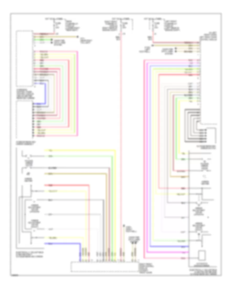
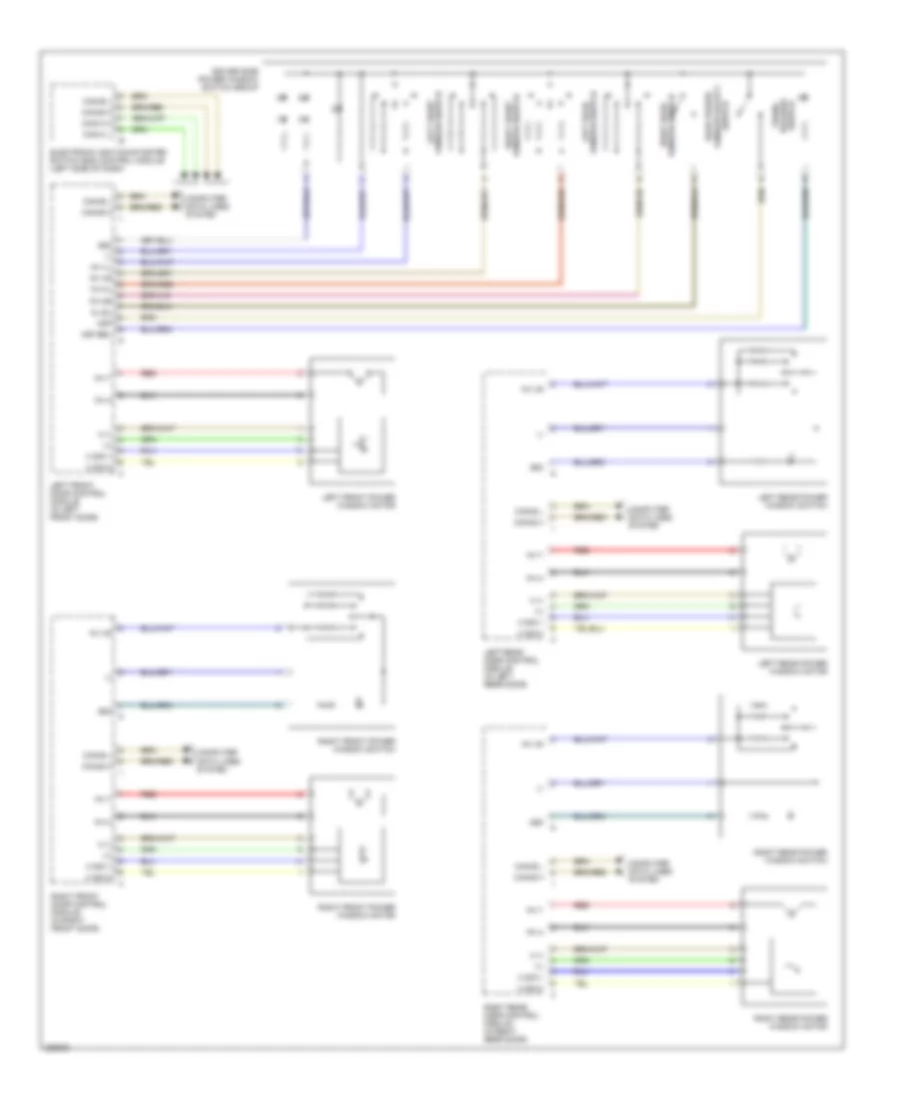
MEMORY SYSTEMS Driver"s Memory Seat Wiring Diagram (1 of 2) for Mercedes-Benz S500 2005 List of elements for Driver"s Memory Seat Wiring Diagram (1 of 2) for Mercedes-Benz S500 2005: 40 Backrest adjustment motor (fore/aft) Can-b h Can-b l Computer data lines system Electronic ignition-starter switch control module (left side of dash) Front seat adjustment motor (fore/aft) Front seat adjustment motor (raise/lower) Gs/ab Head restraint adjustment motor (raise/lower) Hh (+) Hh (-) Hv (+) Hv (-) K (+) L (+) Left front door control module (in left front door) Left front electric seat adjustment control module (below left front seat) Left front seat adjust motor group Left front seat belt buckle microswitch Left front seat belt buckle switch (restraint system) Left front seat switches Lk (-) Mhh (+) Mhh (-) Mhv (+) Mhv (-) Mk (-) Ml (-) Mlk (+) Mskt (+) Mskt (-) Mvz (+) Mvz (-) Rear seat adjustment motor (raise/lower) Red Seat cushion adjustment motor (fore/aft) Skt (+) Skt (-) Vz (+) Vz (-) Driver"s Memory Seat Wiring Diagram (2 of 2) for Mercedes-Benz S500 2005 List of elements for Driver"s Memory Seat Wiring Diagram (2 of 2) for Mercedes-Benz S500 2005: 37 (at left door sill) w28/1 58d Can-b h Can-b l Computer data lines system Fuse 25a Hkl Hks Hot at all times L35 Left front backrest heater element Left front door switch Left front multi-contour backrest control module (under left front seat) Left front multi-contour backrest switch Left front seat adjustment control module (under left front seat) Left front seat cushion heater element Left front seat cushion ventilation motor group Left front seat ventilation blower regulator (inside backrest of left front seat) Left front seatback ventilation motor group Left rear door switch Lf door Lr door Passive restraint system Rear fuse/relay module (under right rear seat) Rear sam control module (under right rear seat) Red Rf door Right front door switch Right rear door switch Rr door Trnk Trunk lid micro- switch W17/1 (under left rear seat) W26 (below center console) W28/1 (at left door sill) W28/2 (at right door sill) W7/1 (near right taillight) Memory Mirrors Wiring Diagram for Mercedes-Benz S500 2005 List of elements for Memory Mirrors Wiring Diagram for Mercedes-Benz S500 2005: 22 (in left front door) Automatic dimming mirror Computer data lines system Electrically adjustable & heated driver side outside rearview mirror Electrically adjustable & heated right outside rearview mirror Folding mirror motor Fuse 40a Hot at all times L19 Left front door control module Left front fuse/relay module (left rear of engine compt) Mirror adjustment motor (in/out) Mirror adjustment motor (up/down) Mirror heater Nca Outside rearview mirror switch Pnk Red Right front door control module (in right front door) Right front fuse/relay module (right rear of engine compt) W15/2 (left footwell) W36/1 (right footwell) Passenger"s Memory Seat Wiring Diagram (1 of 2) for Mercedes-Benz S500 2005 List of elements for Passenger"s Memory Seat Wiring Diagram (1 of 2) for Mercedes-Benz S500 2005: 40 Backrest adjustment motor (fore/aft) Can-b h Can-b l Computer data lines system Electronic ignition-starter switch control module (left side of dash) Front passenger seat occupied & child seat recognition module Front seat adjustment motor (fore/aft) Front seat adjustment motor (raise/lower) Gs/ab Head restraint adjustment motor (raise/lower) Hh (+) Hh (-) Hv (+) Hv (-) K (+) L (+) Left front seat switches Lk (-) Mhh (+) Mhh (-) Mhv (+) Mhv (-) Mk (-) Ml (-) Mlk (+) Mskt (+) Mskt (-) Mvz (+) Mvz (-) Rear seat adjustment motor (raise/lower) Red Right front door control module (in right front door) Right front electric seat adjustment control module (under right front seat) Right front seat adjust motor group Right front seat belt buckle microswitch Right front seat belt buckle switch (restraint system) Seat cushion adjustment motor (fore/aft) Skt (+) Vz (+) Vz (-) Passenger"s Memory Seat Wiring Diagram (2 of 2) for Mercedes-Benz S500 2005 List of elements for Passenger"s Memory Seat Wiring Diagram (2 of 2) for Mercedes-Benz S500 2005: 37 (at right door sill) w28/2 58d Can-b h Can-b l Computer data lines system Fuse 25a Hkl Hks Hot at all times L37 Left front backrest heater element Left front door switch Left front seat cushion heater element Left rear door switch Lf door Lr door Passive restraint system Rear fuse/relay module (under right rear seat) Rear sam control module (below right rear seat) Red Rf door Right front door switch Right front multi-contour backrest control module Right front multi-contour backrest switch Right front seat adjustment control module (under right front seat) Right front seat cushion ventilation motor group Right front seat ventilation blower regulator (inside backrest of right front seat) Right front seatback ventilation motor group Right rear door switch Rr door Trnk Trunk lid micro- switch W17/1 (under left rear seat) W26 (below center console) W28/1 (at left door sill) W28/2 (at right door sill) W7/1 (near right taillight) Steering Column Memory Wiring Diagram for Mercedes-Benz S500 2005 List of elements for Steering Column Memory Wiring Diagram for Mercedes-Benz S500 2005: 38 87a Can-b h Can-b l Can-c h Can-c l Computer data lines system Electric steering column motor group Electronic ignition-starter switch control module (left side of dash) Esc in/out assist switch group Fuse 3 15a Fuse 4 15a Height adjustment motor Hot at all times In/out assist switch Instrument cluster Left front door control module (in door) Left front door switch Left front fuse/relay module (left rear of engine compt) Left front sam control module Lf door Longitudinal adjustment motor Memory switch/ memory 1/ memory 2/ ergonomy switch Multifunction display Nca Rear sam control module (below right rear seat) Red Rf door Right front door switch Steering column control module (left side of dash) Steering column driving position switch Steering column height adjustment relay 1 Steering column height adjustment relay 2 Steering column longitudinal adjustment relay 1 Steering column longitudinal adjustment relay 2 Up/down- fore/aft switch W28/1 (at left door sill) W28/2 (at right door sill) W36/2 (right footwell)
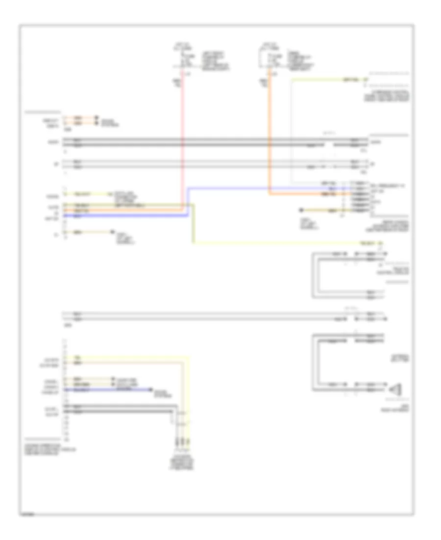
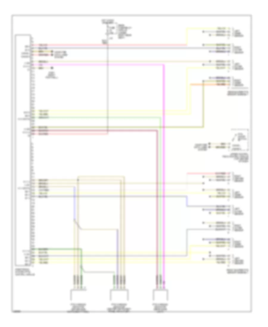
NAVIGATION Navigation Wiring Diagram for Mercedes-Benz S500 2005 List of elements for Navigation Wiring Diagram for Mercedes-Benz S500 2005: 40 Am/fm Ant on Antenna splitter Aux nf Can-b h Can-b l Cc nf gnd Cc nf l Cc nf r Comand operating, display & control module (center console) Computer data lines system Connector (at upper left footwell) D2b D2b in D2b out Data Data link Fuse 15a Fuse 7.5a Gps Gps roof antenna Hot at all times K-diag K1l K2l L12 L33 Left front fuse/relay module (left rear of engine compt) Mute Nca Nca nca Overhead control panel control module (front center of roof) Rcl frequency in Rear fuse/relay module (under right rear seat) Rear window antenna amplifier (center rear of roof) Sound systems Tele aid control module W28/1 (at left doorsill) Wake up Walkman separation connector (if equipped) Parktronic Wiring Diagram for Mercedes-Benz S500 2005 List of elements for Parktronic Wiring Diagram for Mercedes-Benz S500 2005: 42 (+) sh (+) sv (-) sh (-) sv Can-b h Can-b l Computer data lines system Front bumper pts sensor assembly Fuse 10a Hot in run or start L43 Left center sensor Left inner sensor Left outer sensor Parktronic system (pts) control module Pts on/off switch Pts warning indicator (center instrument panel air outlet) Pts warning indicator (driver side instrument panel) Pts warning indicator (rear dome light) Rear bumper pts sensor assembly Rear fuse/relay module (under right rear seat) Right center sensor Right inner sensor Right outer sensor S1 v S10 h S2 v S3 v S4 v S5 v S6 v S7 h S8 h S9 h Upper control field control module (top center of dash) W h (+) W h (-) W h (data) W v (+) W v (-) W v (data) W36/1 (right footwell)
PASSIVE RESTRAINTS Passive Restraints Wiring Diagram for Mercedes-Benz S500 2005 List of elements for Passive Restraints Wiring Diagram for Mercedes-Benz S500 2005: 23 Computer data lines system Fuse 25a Hot at all times L35 L37 Left front esa control module (under left front seat) Left front seat belt buckle microswitch (in left front seat belt buckle) Left front seat belt comfort feature solenoid (base of left "b" pillar) Left rear seat belt buckle/ belt comfort feature switch (in left rear seat belt buckle) Left rear seat belt comfort feature solenoid (base of right "b" pillar) Nca Rear fuse/relay module (under right rear seat) Rear sam control module (below right rear seat) Right front seat adjustment control module (under right front seat) Right front seat belt buckle microswitch (in right front seat belt buckle) Right front seat belt comfort feature solenoid (base of right "b" pillar) Right rear seat belt buckle/ belt comfort feature switch (in right rear seat belt buckle) Right rear seat belt comfort feature solenoid (base of left "b" pillar) W17/1 (under left rear seat) W26 (below front of center console) W28/1 (at left door sill) W28/2 (at right door sill) W7/1 (near right taillight)
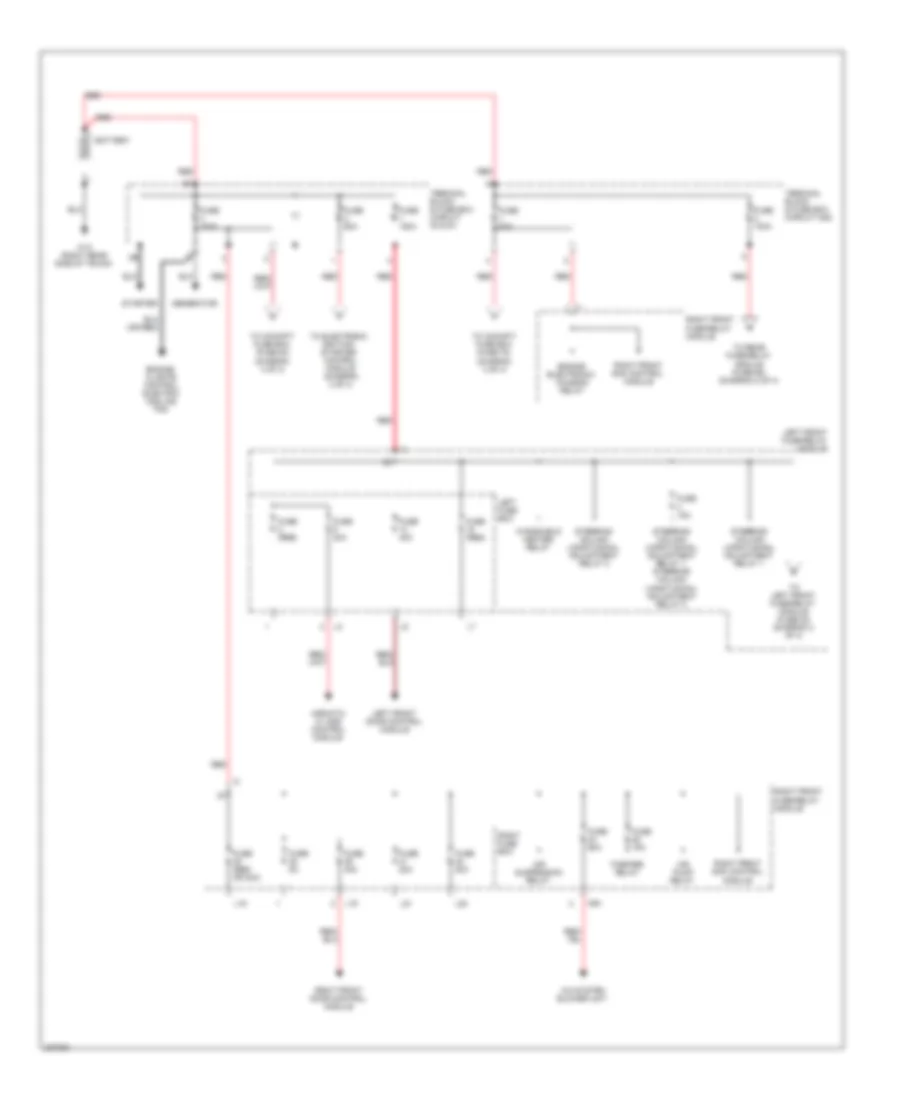
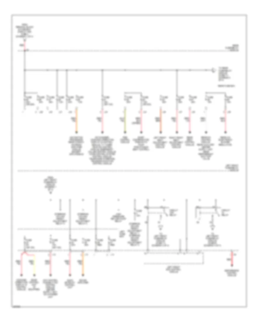
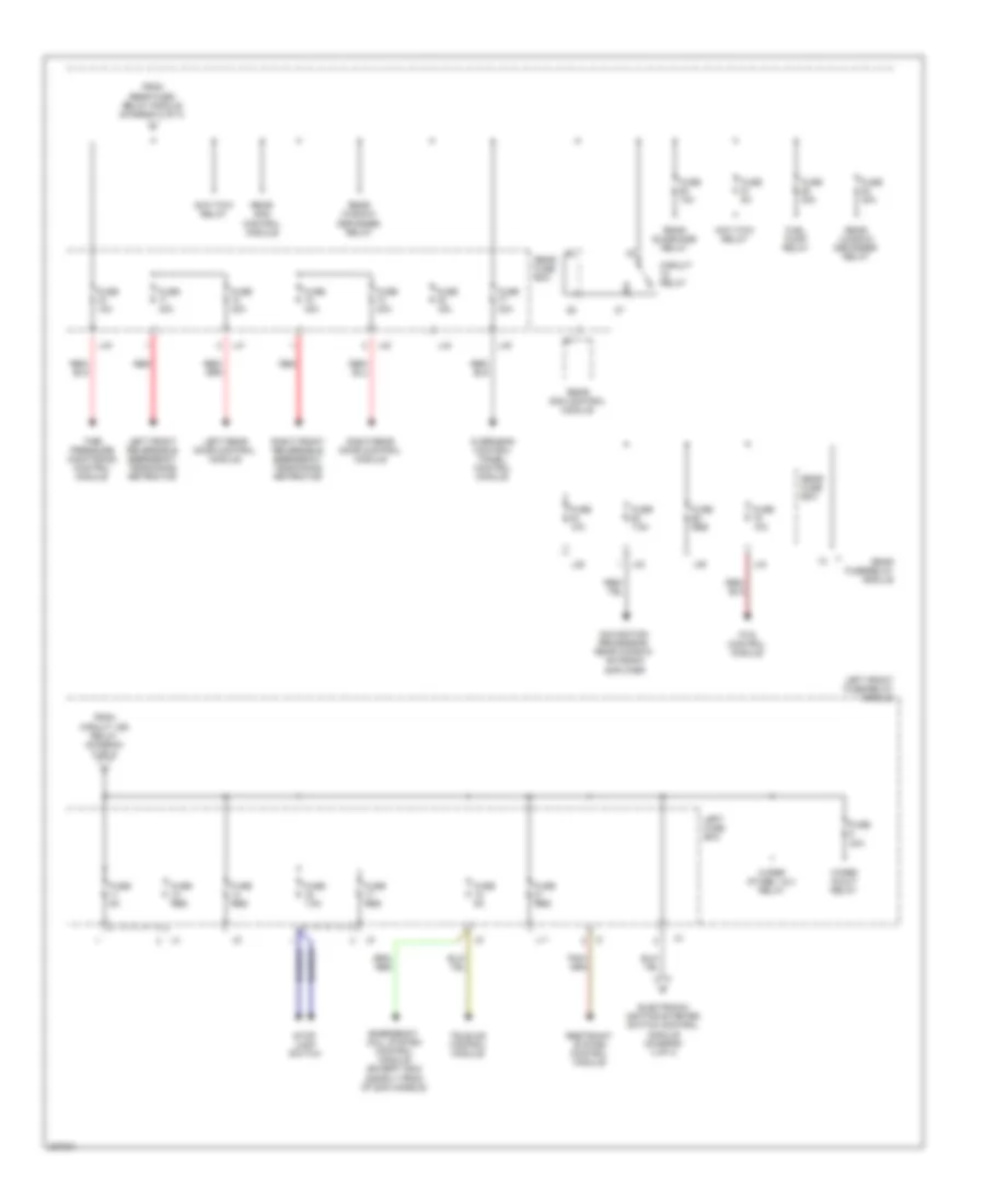
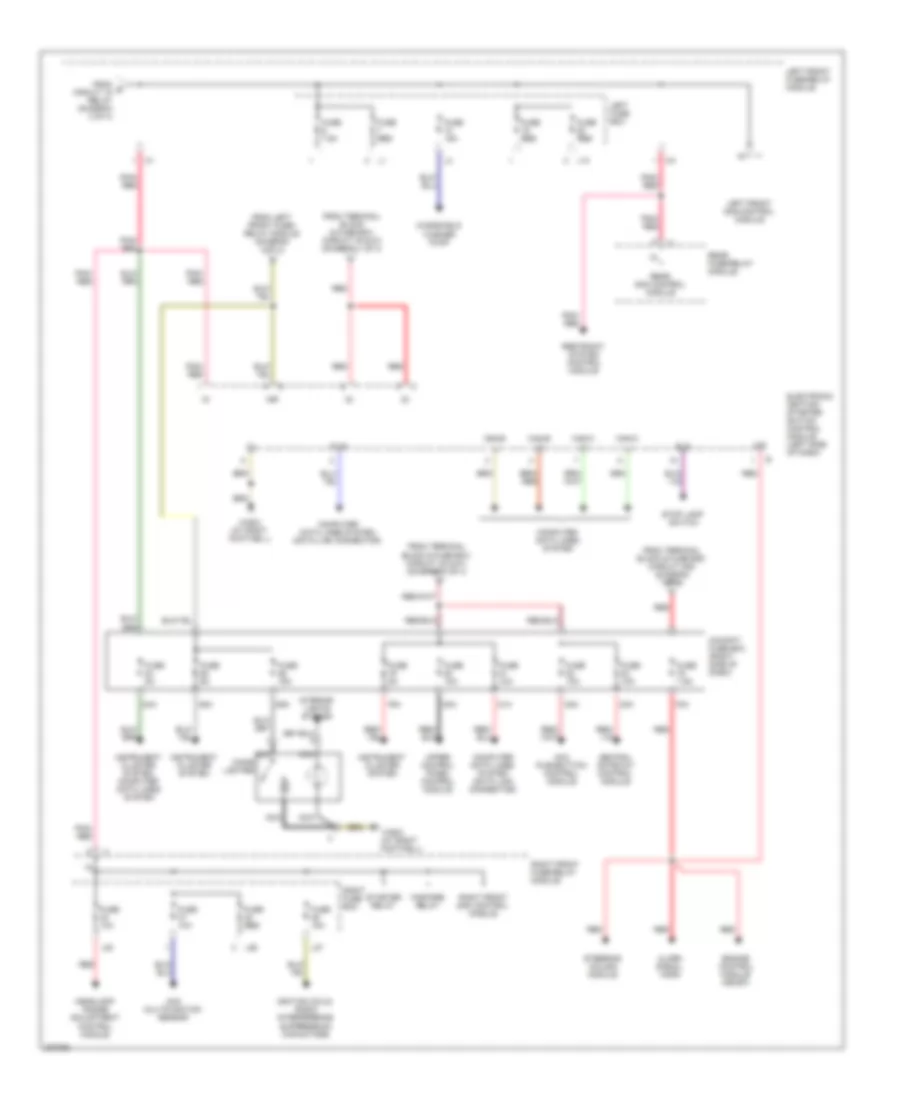
POWER DISTRIBUTION Power Distribution Wiring Diagram (1 of 4) for Mercedes-Benz S500 2005 List of elements for Power Distribution Wiring Diagram (1 of 4) for Mercedes-Benz S500 2005: 45 A/c system blower unit Air pump relay Air suspension relay Airmatic w/ ads control module Battery Engine electronic/ chassis relay Engine/ climate control electric cooling fan Fanfare relay Fuse (res or 30a) Fuse (res) Fuse 100a Fuse 150a Fuse 15a Fuse 20a Fuse 30a Fuse 40a Fuse 5a Fuse 60a Generator L16 L19 L21 L22 Left front door control module Left front fuse/relay module Left fuse box Mr1 Red Right front door control module Right front fuse/relay module Right front sam control module Right fuse box Starter Steering column longitudinal adjustment relay 1 Steering column longitudinal adjustment relay 1, steering column longitudinal adjustment relay 2 Steering column longitudinal adjustment relay 2 Terminal block & fuse box (circuit 30 & 61) Terminal block & fuse box (circuit 30z) To cockpit fuse box (fuse 78) (diagram 4 of 4) To cockpit fuse box (fuse 80) (diagram 4 of 4) To electronic ignition- starter control module (diagram 4 of 4) To left front fuse/relay module (fuse 23) (diagram 2 of 4) To rear fuse/relay module (fuse 55) (diagram 2 of 4) W10 (right rear side of trunk) Windshield heater relay Power Distribution Wiring Diagram (2 of 4) for Mercedes-Benz S500 2005 List of elements for Power Distribution Wiring Diagram (2 of 4) for Mercedes-Benz S500 2005: 55 (or 15a) (or 7.5a) Audio gateway control unit Cd changer, command operating display & control module, tv tuner, tele aid control module, emergency called control module voice control system control module, telephone interface, telecommunication control module Circuit 15r relay Circuit relay Command operating display & control module, E-net compensator, pneumatic pump (for dynamic seat control) Esp/sps/bas control module From left front fuse/relay module (diagram 1 of 4) From terminal block & fuse box (circuit 30z) fuse 2 (diagram 1 of 4) Fuse 10a Fuse 15a Fuse 15a (or 7.5a) Fuse 20a Fuse 25a Fuse 30a Fuse 30a (or 25a) Fuse 5a Fuse 7.5a Fuse 7.5a (or 30a) Fuse res High pressure return pump relay L12 L13 L14 L29 L30 L31 L32 L33 L34 L35 L37 L38 L39 Left front fuse/relay module Left front sam control module Left front seat adjustment control module Left fuse box Navigation processor, rear window antenna amplifier module (except 2003 models) Pse control module Rear a/c electronic blower regulator, Rear fuse box Rear fuse/relay module Rear seat control module Red Right front seat adjustment control module Sdar control unit (if equipped) Sound amplifier Steering column height adjustment relay 1, steering column height adjustment relay 2 Steering column height adjustment relay 2 To left front fuse/relay module (fuse 11) (diagram 3 of 4) To left front fuse/relay module (fuse 6) (diagram 4 of 4) To rear fuse/relay module (fuse 71) (diagram 3 of 4) Power Distribution Wiring Diagram (3 of 4) for Mercedes-Benz S500 2005 List of elements for Power Distribution Wiring Diagram (3 of 4) for Mercedes-Benz S500 2005: 45 Anti-tow relay Circuit relay Electronic ignition-starter switch control module (diagram 4 of 4) Emergency call system control module (except 2003 & early prod of 2004 models) From circuit 15r relay (diagram 2 of 4) From rear fuse/ relay module (diagram 2 of 4) Fuel pump relay Fuse 10a Fuse 15a Fuse 30a Fuse 40a Fuse 5a Fuse 7.5a Fuse res L11 L28 L33 L36 L40 L41 L42 L43 L44 L45 Left front fuse/relay module Left front reversible emergency tensioning retractor Left fuse box Left rear door control module Navigation processor, rear window antenna amplifier Overhead control panel control module Pts control module Rear fuse box Rear fuse/relay module Rear sam control module Rear sunshade relay Rear window defogger relay Red Restraint system control module Right front reversible emergency tensioning retractor Right rear door control module Stop lamp switch Tele-aid control module Tire pressure monitoring control module Wiper in/out relay Wiper stage 1 & 2 relay Power Distribution Wiring Diagram (4 of 4) for Mercedes-Benz S500 2005 List of elements for Power Distribution Wiring Diagram (4 of 4) for Mercedes-Benz S500 2005: 64 15r 30z 78a 79a 80a 81a 82a 83a 84a 85a 86a Aac multifunction sensor Acc pushbutton control module Alarm signal horn Bls Can-b h Can-b l Can-c h Can-c l Central gateway control module Cigar lighter Cockpit fuse box (right side of dash) Computer data lines system Computer data lines system (data link connector) Diag Electronic ignition- starter switch control module (left side of dash) Engine control module (me-sfi) Fanfare relay From e circuit 15 relay (diagram 2 of 4) From left front fuse/ relay module (diagram 3 of 4) From terminal block & fuse box (circuit 30 & 61) (diagram 1 of 4) From terminal block & fuse box (circuit 30z) (diagram 1 of 4) Fuse 10a Fuse 15a Fuse 5a Fuse 7.5a Fuse res Headlamp range adjustment control module Ignition coils, radio interference suppression capacitors Instrument cluster system Instrument cluster system, computer data lines system Interior lights system L10 L20 L26 L27 Left front fuse/relay module Left front sam control module Left fuse box Nca Pnk/ red Rear fuse/relay module Rear sam control module Red Restraint system control module Right front fuse/relay module Right front sam control module Right fuse box Starter relay Steering column module Stop lamp switch Upper control panel control module W36/2 (at right footwell) Windshield washer pump
POWER DOOR LOCKS Power Door Locks Wiring Diagram (1 of 2) for Mercedes-Benz S500 2005 List of elements for Power Door Locks Wiring Diagram (1 of 2) for Mercedes-Benz S500 2005: 43 +12v 49a Can-b h Can-b l Can-c h Can-c l Combination switch Computer data lines system Df vl Electronic ignition-starter switch (eis) control module (left side of dash) Esp/sps/bas control module (in left fuse box) Exterior lights system Hd-svs Instrument cluster Interior central locking system switch, hazard warning system switch L/r turn sig sw Left front door switch Left front sam control module (in fuse/relay box, left side) Left front vss (on left front wheelhouse) Left rear door switch Lf dr sw Lr dr sw Lr turn sig Nca Pneumatic system equipment (pse) control module (left of trunk) Pse control module (left side of trunk) Rear sam control module (under right rear seat) Remote trunk lid opening valve Rf dr sw Right front door switch Right front sam control module (in fuse/relay box, right side) Right rear door switch Rr dr sw Rr turn sig Steering column module (left inside of dash) Trunk lid closing assist micro- switch Trunk lid emergency release switch Trunk lid sw Upper control field control module (at top center of dash) W17/1 (under left rear seat) W28/1 (at left door sill) W28/2 (at right door sill) W7/1 (near right taillight) Power Door Locks Wiring Diagram (2 of 2) for Mercedes-Benz S500 2005 List of elements for Power Door Locks Wiring Diagram (2 of 2) for Mercedes-Benz S500 2005: 30 (-) Ask Ask (-) Bl (+) Bl (-) Can-b h Can-b l Computer data lines system Ir (+) Ir (-) Ir-daten Left front door control module (in left front door) Left front door lock switch (cf) Left front door power locking drive pawl microswitch Left front ir receiver Left outside mirror turn signal lamp Left rear door control module (in left rear door) Left rear door power locking drive pawl microswitch Lock Pnk Right front door control module (in right front door) Right front door power locking drive pawl microswitch Right front ir receiver Right outside mirror turn signal lamp Right rear door control module (in right rear door) Right rear door power locking drive pawl microswitch Sn1/sn2 Unlock V (-) Zzh-v
POWER MIRRORS Power Mirrors Wiring Diagram for Mercedes-Benz S500 2005 List of elements for Power Mirrors Wiring Diagram for Mercedes-Benz S500 2005: 28 (in left front door) Automatic dimming mirror Computer data lines system Electrically adjustable & heated driver side outside rearview mirror Electrically adjustable & heated right outside rearview mirror Folding mirror motor Fuse 40a Hot at all times Interior rearview mirror assembly L19 L45 Left front door control module Left front fuse/relay module (left rear of engine compt) Mirror adjustment motor (in/out) Mirror adjustment motor (up/down) Mirror heater Nca Outside rearview mirror switch Overhead control panel control module (above center rearview mirror) Pnk Pnk/red Rear fuse/relay module (under right rear seat) Red Right front door control module (in right front door) Right front fuse/relay module (right rear of engine compt) W15/2 (left footwell) W36/1 (right footwell) W7/1 (near right taillight)
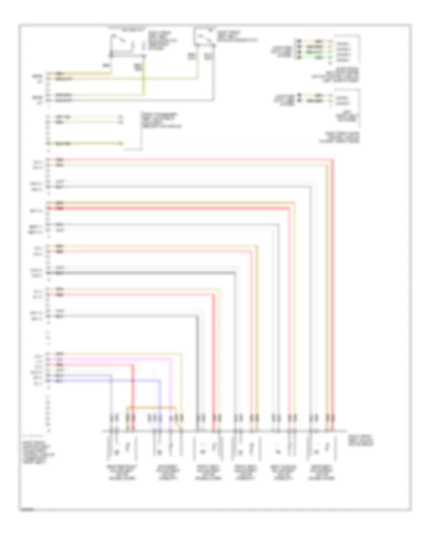
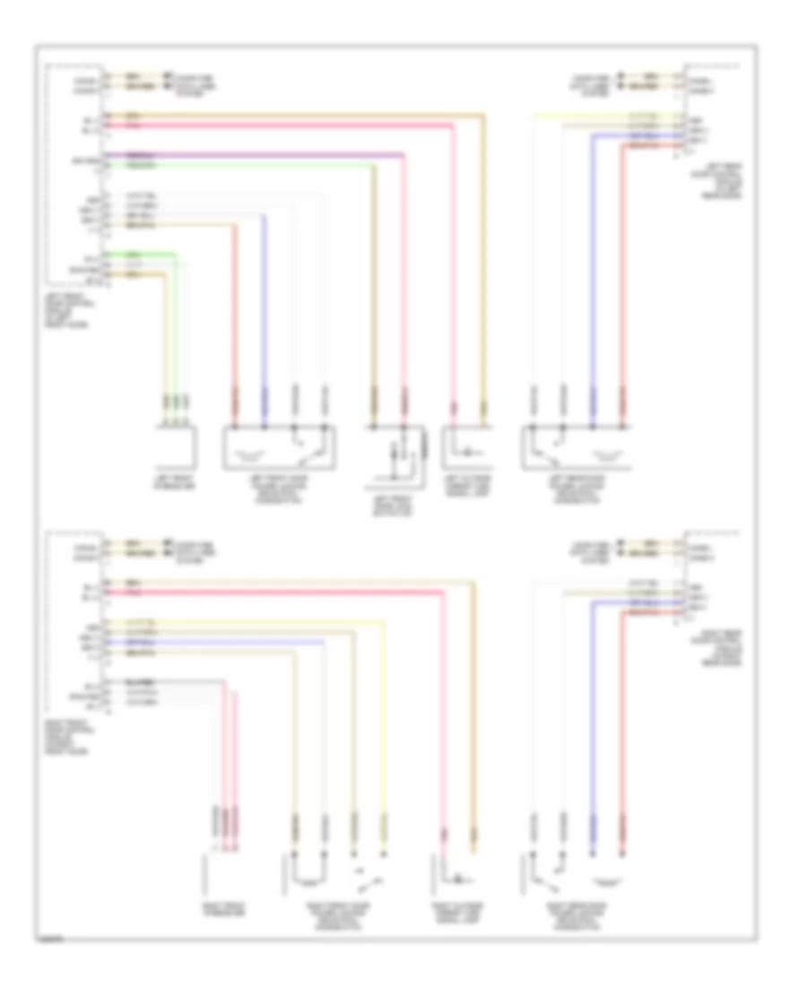
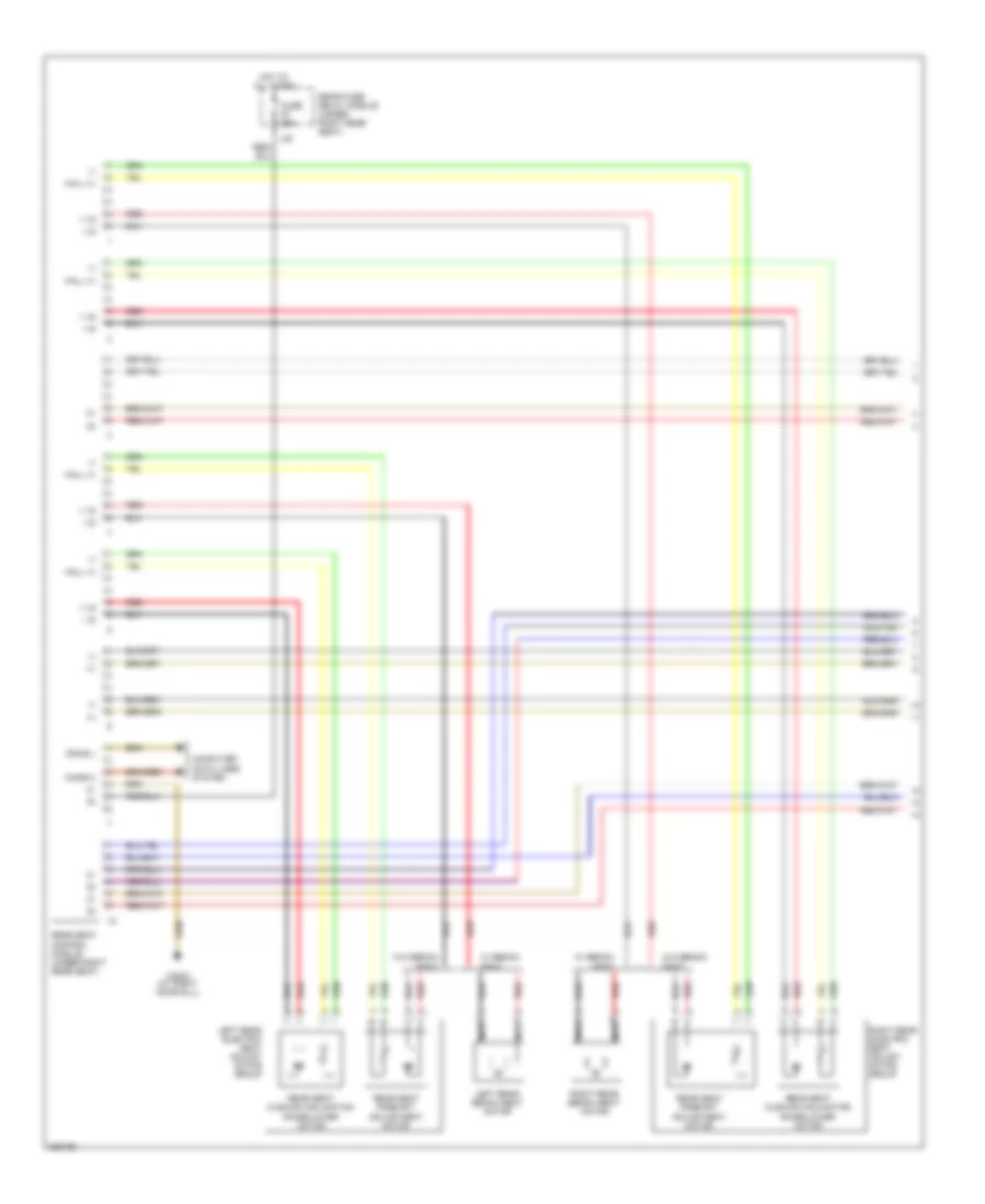
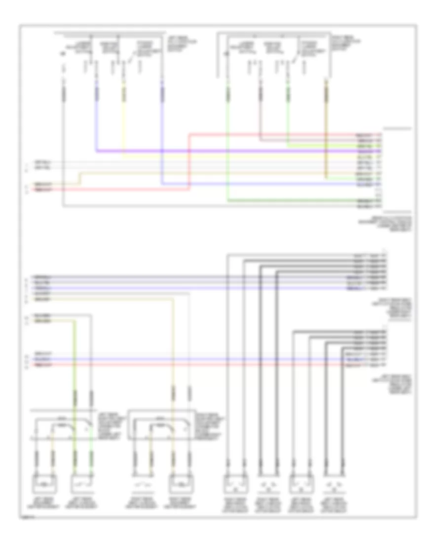
POWER SEATS Rear Head Restraint Wiring Diagram for Mercedes-Benz S500 2005 List of elements for Rear Head Restraint Wiring Diagram for Mercedes-Benz S500 2005: 34 Can-b h Can-b l Can-c h Can-c l Computer data lines system Electronic ignition-starter switch (eis) control module (left side of dash) Head restraint height/lower adjustment switch Head restraint raise valves Left front door switch Left head restraint raise valve Left rear door control module (in left rear door) Left rear door switch Left rear seat belt buckle/belt comfort feature switch Lf dr sw Lr dr sw Middle head restraint raise valve Nca Pse control module (on left side of trunk) Rear headrest switch Rear sam control module (below right rear seat) Rf dr sw Right front door switch Right head restraint raise valve Right rear door control module (in right rear door) Right rear door switch Right rear seat belt buckle/belt comfort feature switch Rr dr sw Seat belt sw Upper control field control module (at top center of dash) W17/1 (under left rear seat) W28/1 (at left door sill) W28/2 (at right door sill) W28/2 (right inside rocker panel) W7/1 (near right taillight) Rear Power Seat Wiring Diagram (1 of 2) for Mercedes-Benz S500 2005 List of elements for Rear Power Seat Wiring Diagram (1 of 2) for Mercedes-Benz S500 2005: 24 (+) (-) + vz - vz Can-b h Can-b l Computer data lines system Fuse 25a Hall (+) Hot at all times L38 Left rear bench seat motor Left rear electric seat adjust motor group Nca Rear fuse/ relay module (under right rear seat) Rear seat control module (under right rear seat) Rear seat cushion inclination raise/lower motor Rear seat fore/aft adjustment motor Red Right rear bench seat motor Right rear electric seat adjust motor group W/ bench seat W/o bench seat W28/2 (at right door sill) Rear Power Seat Wiring Diagram (2 of 2) for Mercedes-Benz S500 2005 List of elements for Rear Power Seat Wiring Diagram (2 of 2) for Mercedes-Benz S500 2005: 19 Dynamic lumbar adjustment switch Left rear backrest heater element Left rear electric seat adjustment connector block (under left rear seat) Left rear multi-contour backrest switch Left rear seat cushion heater element Left rear seat cushion ventilation motor group Left rear seat ventilation blower regulator (under left rear seat) Left rear seatback ventilation motor group Lumbar adjustment switch Nca Rear multi-contour backrest control module (under center of rear seat) Right rear backrest heater element Right rear electric seat adjustment connector block (under right rear seat) Right rear multi-contour backrest switch Right rear seat cushion heater element Right rear seat cushion ventilation motor group Right rear seat ventilation blower regulator (under right rear seat) Right rear seatback ventilation motor group Side pad adjust switch
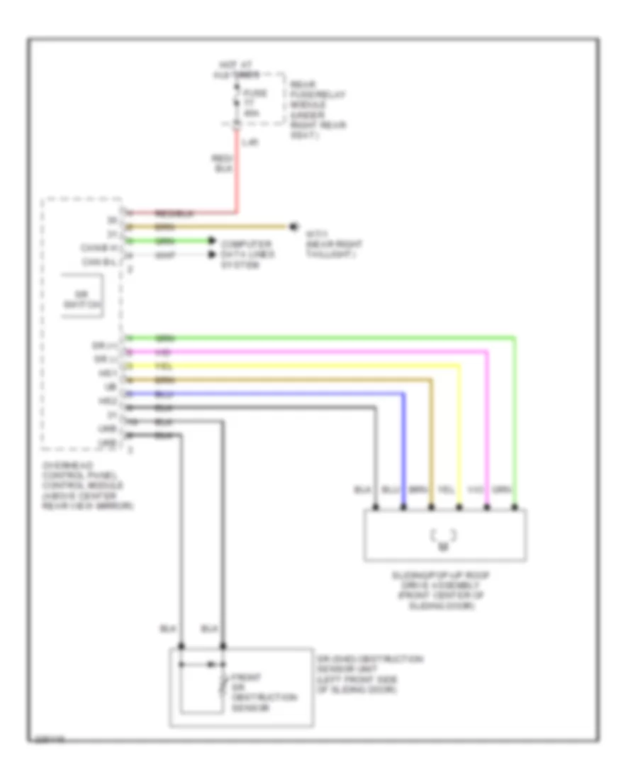
POWER TOP/SUNROOF Power Top/Sunroof Wiring Diagram for Mercedes-Benz S500 2005 List of elements for Power Top/Sunroof Wiring Diagram for Mercedes-Benz S500 2005: 18 Can b-l Can-b h Computer data lines system Front sr obstruction sensor Fuse 40a Hot at all times Hs1 Hs2 L45 Overhead control panel control module (above center rear view mirror) Rear fuse/relay module (under right rear seat) Sliding/pop-up roof drive assembly (front center of sliding door) Sr (+) Sr (-) Sr (shd) obstruction sensor unit (left front side of sliding door) Sr switch Ukb W7/1 (near right taillight)
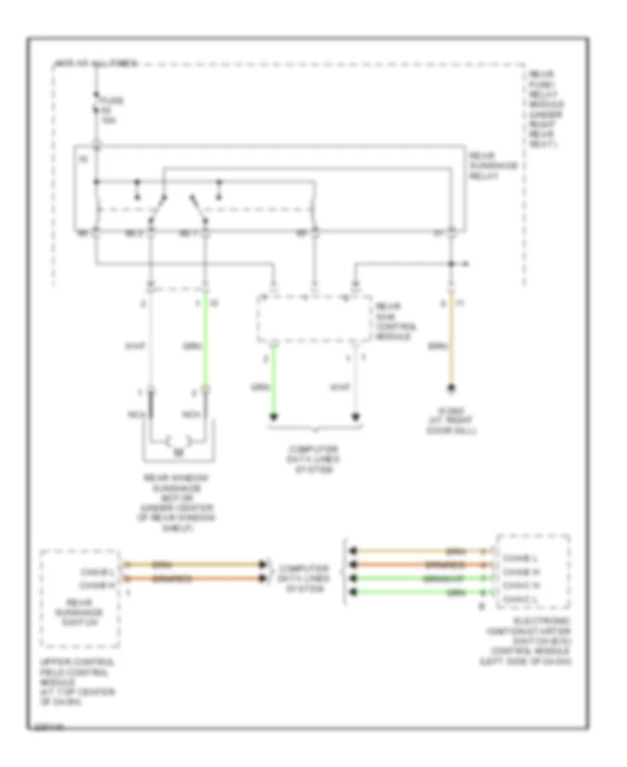
POWER WINDOWS Power Windows Wiring Diagram for Mercedes-Benz S500 2005 List of elements for Power Windows Wiring Diagram for Mercedes-Benz S500 2005: 40 (+) (-) 58d Can-b h Can-b l Can-c h Can-c l Computer data lines system Driver side power window switch group Electronic ignition-starter switch (eis) control module (left side of dash) Fh h Fh hl Fh hr Fh t Fh vl Fh vr H (-) H sig 1 H sig 2 Hdf Hdf bel Kl-sl Left front door control module (in left front door) Left front power window motor Left rear door control module (in left rear door) Left rear power window motor Left rear power window switch Left rear window switch Red Right front door control module (in right front door) Right front power window motor Right front power window switch Right front window switch Right rear door control module (in right rear door) Right rear power window motor Right rear power window switch Right rear window switch Switch release trunk Switch window safety rear power Window switch left front Rear Window Sun Shade Wiring Diagram for Mercedes-Benz S500 2005 List of elements for Rear Window Sun Shade Wiring Diagram for Mercedes-Benz S500 2005: 18 88.1 88.2 Can-b h Can-b l Can-c h Can-c l Computer data lines system Electronic ignition-starter switch (eis) control module (left side of dash) Fuse 10a Hot at all times Nca Rear fuse/ relay module (under right rear seat) Rear sam control module Rear sunshade relay Rear sunshade switch Rear window sunshade motor (under center of rear window shelf) Upper control field control module (at top center of dash) W28/2 (at right door sill)
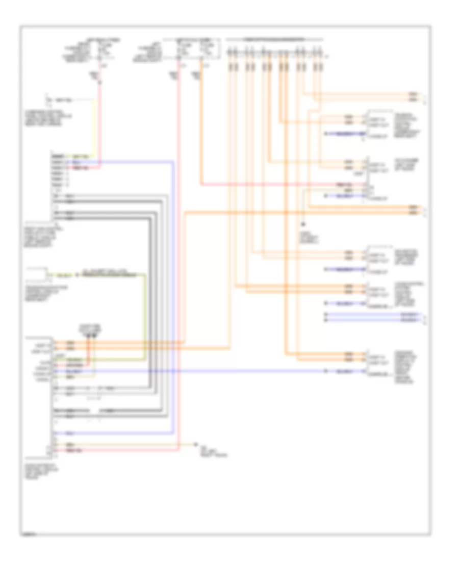
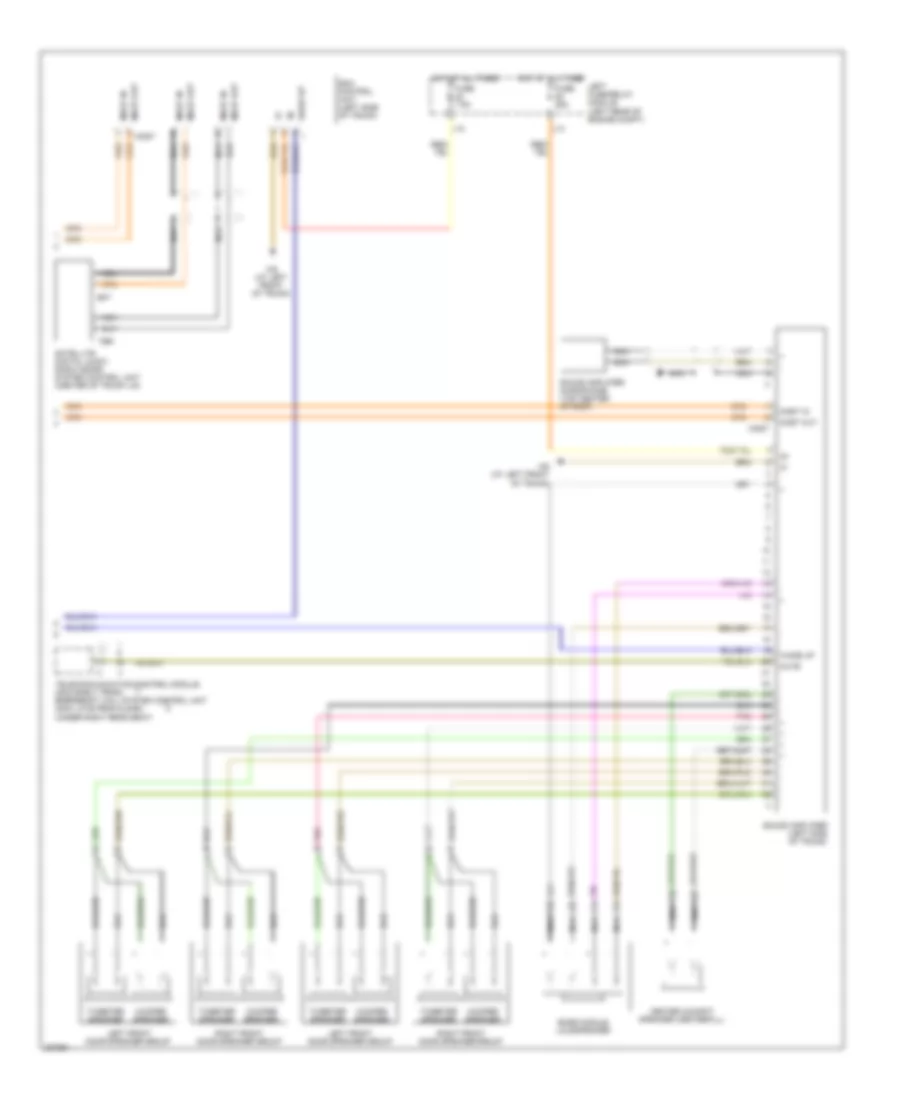
RADIO Radio Wiring Diagram (1 of 2) for Mercedes-Benz S500 2005 List of elements for Radio Wiring Diagram (1 of 2) for Mercedes-Benz S500 2005: 31 (all except 2004 late production & 2005 models) Audio gateway control module (let side of trunk) C11 Can-b h Can-b l Cd changer (left side of trunk) Command operating display & control module (front center console) Computer data lines system Fiber optic cable connector Front sam control module w/ fuse & relay module (left rear of engine compt) Fuse 20a Fuse 7.5a Hot at all times L12 L13 L33 Left fuse/relay module (left rear of engine compt) Most Most in Most out Mute Navigation processor (left side of trunk) Nca Overhead control panel control module (above center of rear view mirror) Rear fuse/relay module (under right rear seat) Telecom- munication control module (under right rear seat) Telecommunications control module (under right rear seat) Voice control system control module (left side of trunk) W28/2 (at right doorsill) W6 (at left front trunk) Wake up Radio Wiring Diagram (2 of 2) for Mercedes-Benz S500 2005 List of elements for Radio Wiring Diagram (2 of 2) for Mercedes-Benz S500 2005: 27 Bass module loudspeaker Center cockpit speaker (centerfill) Fuse 25a Fuse 7.5a Hot at all times L12 L13 Left fuse/relay module (left rear of engine compt) Left front door speaker group Most Most in Most out Mute Nca Pnk Right front door speaker group Sat Satellite digital audio radio (sdar) system control unit (center of trunk lid) Sda control unit (left side of trunk) Sound amplifier (left side of trunk) Sound amplifier microphone (top center of roof) Telecommunication control module (2004 early prod) emergency call system control unit (2004 late prod & 2005) (under right rear seat) Ter Tweeter speaker W6 (at left front of trunk) Wake up Woofer speaker
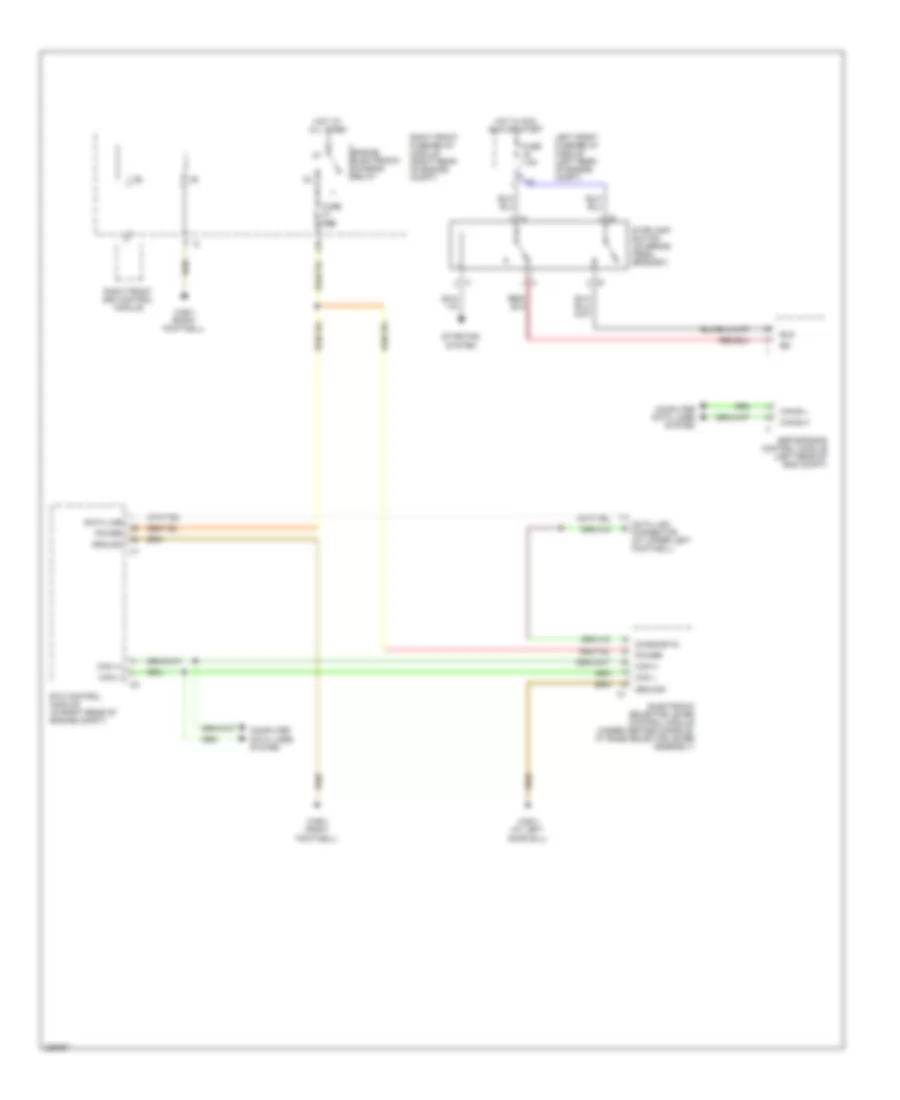
SHIFT INTERLOCK Shift Interlock Wiring Diagram for Mercedes-Benz S500 2005 List of elements for Shift Interlock Wiring Diagram for Mercedes-Benz S500 2005: 29 Bls Can (+) Can (-) Can h Can l Can-b h Can-b l Computer data lines system Data line Data link connector (at upper left footwell) Diagnostic Electronic selector lever control module (under center console, at base selector lever assembly) Engine electronic/ chassis relay Esp/sps/bas control module (left rear of eng compt) Etc control module (in right rear of engine compt) Fuse 15a Fuse 7.5a Ground Hot at all times Hot in acc, run or start L18 Left front fuse/relay module (left rear of engine compt) Power Right front fuse/relay module (right rear of engine compt) Right front sam control module Starting system Stoplamp switch (on brake pedal bracket) W28/1 (at left door sill) W36/1 (right footwell)
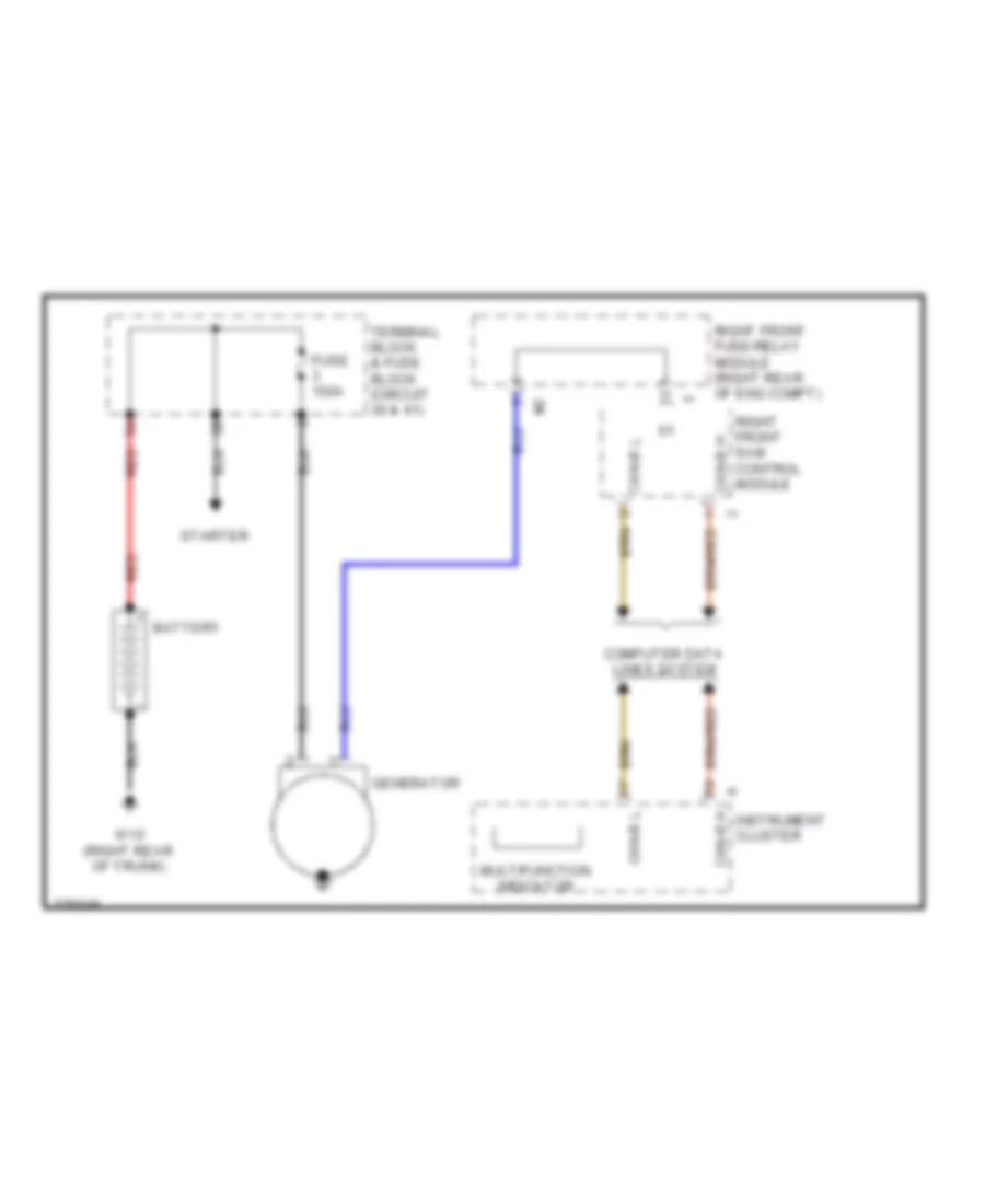
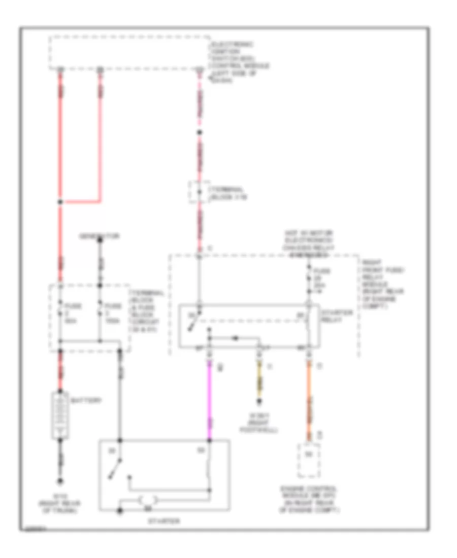
STARTING/CHARGING Charging Wiring Diagram for Mercedes-Benz S500 2005 List of elements for Charging Wiring Diagram for Mercedes-Benz S500 2005: 14 Battery Can-b h Can-b l Computer data lines system Fuse 150a Generator Instrument cluster Multifunction indicator Red Right front fuse/relay module (right rear of eng compt) Right front sam control module Starter Terminal block & fuse block (circuit 30 & 61) W10 (right rear of trunk) Starting Wiring Diagram for Mercedes-Benz S500 2005 List of elements for Starting Wiring Diagram for Mercedes-Benz S500 2005: 17 Battery Electronic ignition switch (eis) control module (left side of a a dash) Engine control module (me-sfi) (in right rear of engine compt) Fuse 150a Fuse 20a Fuse 60a Generator Hot w/ motor electronics/ chassis relay energized Pnk/red Red Right front fuse/ relay module (right rear of engine compt) Starter Starter relay Terminal block & fuse block (circuit 30 & 61) Terminal block x18 W10 (right rear of trunk) W36/1 (right footwell)
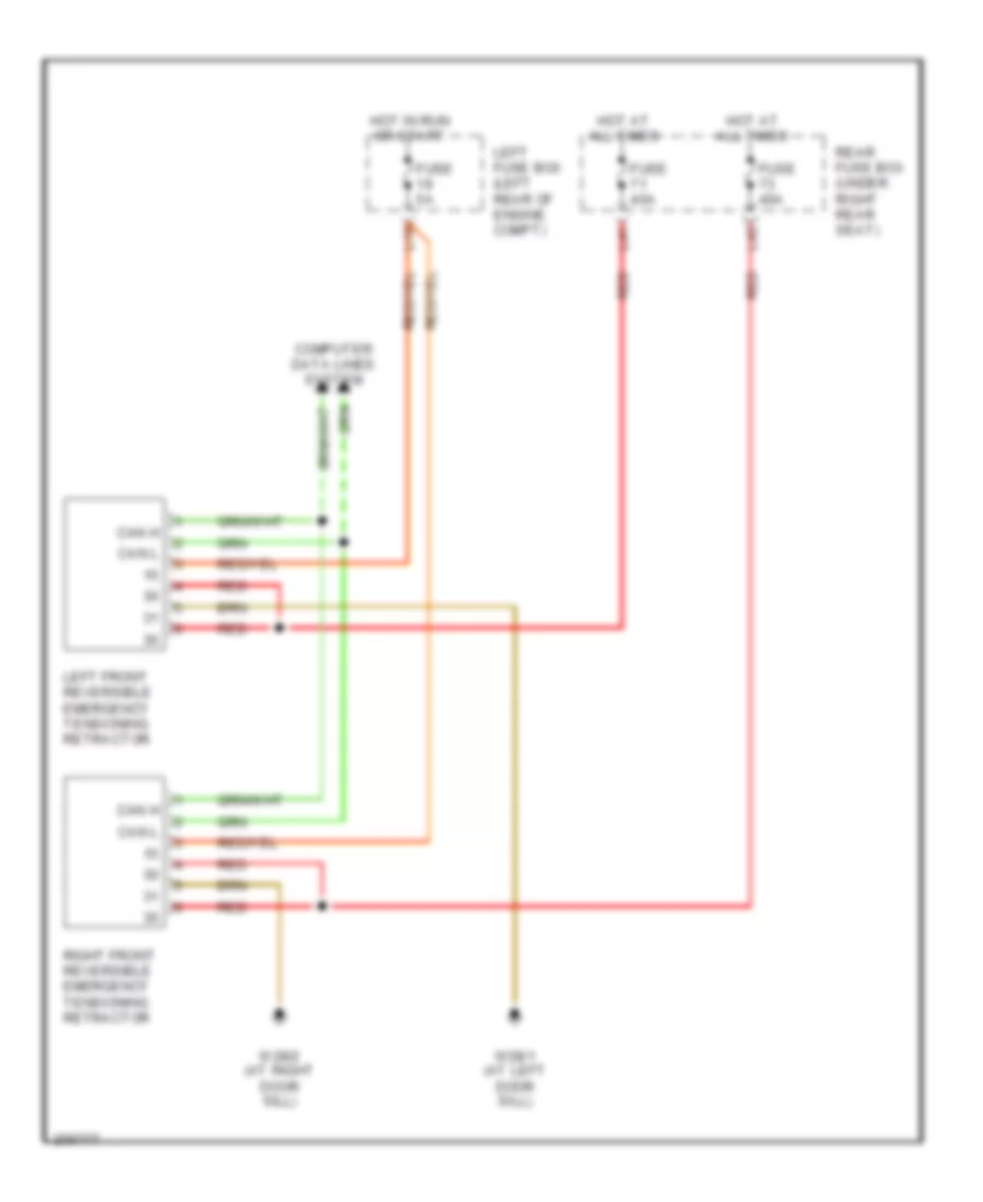
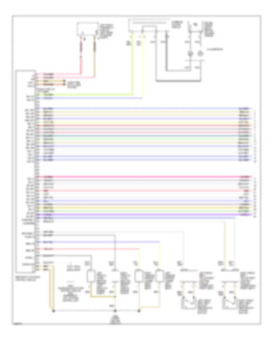
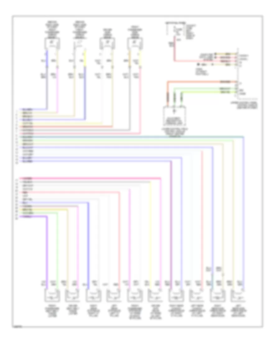
SUPPLEMENTAL RESTRAINTS Emergency Seat Belt Tensioners Wiring Diagram for Mercedes-Benz S500 2005 List of elements for Emergency Seat Belt Tensioners Wiring Diagram for Mercedes-Benz S500 2005: 17 Can h Can l Computer data lines system Fuse 40a Fuse 5a Hot at all times Hot in run or start L10 L41 L42 Left front reversible emergency tensioning retractor Left fuse box (left rear of engine compt) Rear fuse box (under right rear seat) Red Right front reversible emergency tensioning retractor W28/1 (at left door sill) W28/2 (at right door sill) Supplemental Restraints Wiring Diagram (1 of 2) for Mercedes-Benz S500 2005 List of elements for Supplemental Restraints Wiring Diagram (1 of 2) for Mercedes-Benz S500 2005: 63 (2004) (2005) (pins 5 thru 32: not used) 15r 2004: telecommunications control module 2005: emergency call system control unit Ab, fa+ Ab, fa- Ab1, bf+ Ab1, bf- Ab2, bf+ Ab2, bf- Accel l Accel r Akse/sbe Can h Can l Clockspring Computer data lines system Crash sig Driver airbag squib (behind drivers airbag) Drvr belt Gs, bf+ Gs, bf- Gs, f+ Gs, f- Gs, hl+ Gs, hl- Gs, hr+ Gs, hr- Left airbags sensor (under left rear seat) Left front fuse/relay module (left rear of engine compt) i2 Left front seat adjustment control module (under left front seat) Left front seat belt buckle restraints system switch Left frontal accel- eration sensor (left front of engine compt) Nca Pass belt Pnk/red Red Restraint systems control module Right airbags sensor (under right rear seat) Right front seat adjustment control module (under right front seat) Right front seat belt buckle restraints system switch Right frontal accel- eration sensor (right side of engine compt) Sb, bf+ Sb, bf- Sb, f+ Sb, f- Sb, hl+ Sb, hl- Sb, hr+ Sb, hr- Sbs, bf Sbs, fa Ss, bf+ Ss, bf- Ss, f+ Ss, f- Steering column module W26 (under center console) Wb, l+ Wb, l- Wb, r+ Wb, r- Supplemental Restraints Wiring Diagram (2 of 2) for Mercedes-Benz S500 2005 List of elements for Supplemental Restraints Wiring Diagram (2 of 2) for Mercedes-Benz S500 2005: 28 (behind right side of dash) front passenger airbag squib 1 (behind right side of dash) front passenger airbag squib 2 58d 80a Akse Can-b h Can-b l Child seat recognition warning lamp Cockpit fuse box (right side of dash) Computer data lines system Driver etr squib (at base of left "b" pillar) Driver seat belt force limiter Driver side airbag squib Front passenger etr squib (at base of right "b" pillar) Front passenger seat belt force limiter Front passenger side airbag squib Fuse 10a Hot at all times Left rear etr squib (left "c" pillar) Left rear side airbag squib (at left rear door) Left rear window airbag squib (at left "c" pillar) Lower control field control module (front center console) Red Right rear etr squib (right "c" pillar) Right rear side airbag squib (at right rear door) Right rear window airbag squib (at right "c" pillar) Upper control panel control module (center of dash) W36/2 (at right footwell)
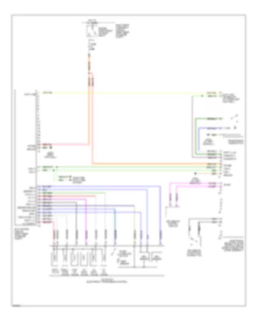
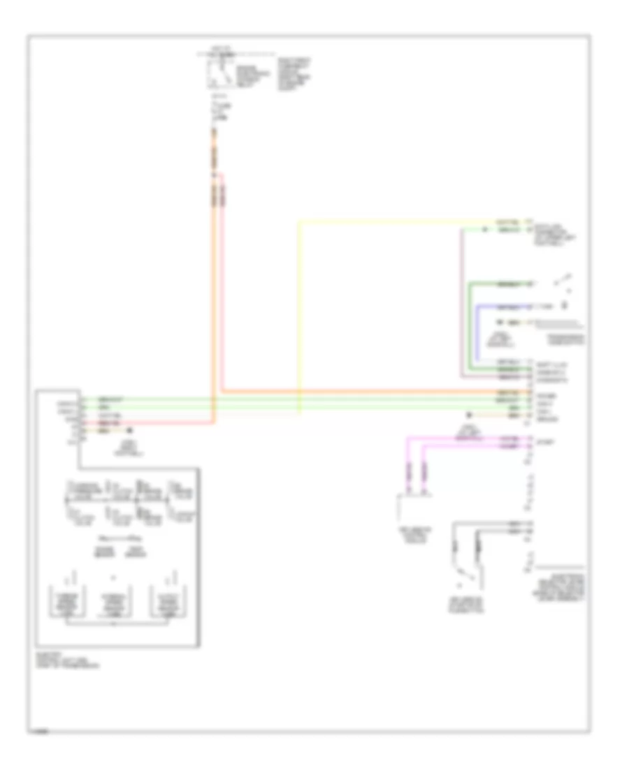
TRANSMISSION A/T Wiring Diagram, 5 Speed for Mercedes-Benz S500 2005 List of elements for A/T Wiring Diagram, 5 Speed for Mercedes-Benz S500 2005: 47 1-2/ 4-5 valve 1-2/4-5 vlv 2-3 shift valve 2-3 vlv 3-4 shift valve 3-4 vlv Can (+) Can (-) Can h Can l Computer data lines system Data line Data link connector (at upper left footwell) Diagnostic Electronic selector lever control module (base of selector lever assembly) Engine electronic/ chassis relay Etc control module (right rear of engine compt) Fuse 15a Ground Hot at all times Keyless go control module Keyless go start/stop pushbutton L18 Lock up valve Mode sw 2 Modul- ator valve Modulator vlv Nca Power Pwm vlv Right front fuse/relay module (right rear of engine compt) Rpm 2 Rpm 3 Rpm sensor Sensor ground Sensor v+ Shift illum Shift valve Shift vlv Start Start interlock switch Temp sensor Temp/start Transmission mode switch Valve unit (electronic transmission control) W28/1 (at left door sill) W36/1 (right footwell) A/T Wiring Diagram, 7 Speed for Mercedes-Benz S500 2005 List of elements for A/T Wiring Diagram, 7 Speed for Mercedes-Benz S500 2005: 39 B1 brake valve B2 brake valve B3 brake valve Can h Can l Can-c h Can-c l Data link connector (at upper left footwell) Diag Diagnostic Electric control unit (vgs) (part of transmission) Electronic selector lever control module (base of selector lever assembly) Engine electronic/ chassis relay Fuse 15a Ground Hot at all times Internal speed sensor (vgs) K1 clutch valve K2 clutch valve K3 clutch valve Keyless go control module Keyless go start/stop pushbutton L18 Lockup valve Mode sw 2 N.c. Nca Output speed sensor (vgs) Power Range sensor Right front fuse/relay module (right rear of engine compt) Shift illum Start Temp sensor Transmission mode switch Turbine speed sensor (vgs) W28/1 (at left door sill) W36/1 (right footwell) Working pressure valve
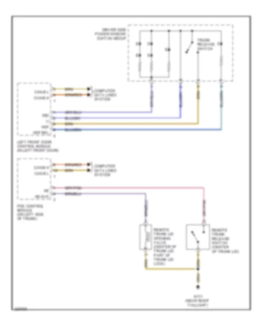
TRUNK, TAILGATE, FUEL DOOR Trunk, Tailgate, Fuel Door Wiring Diagram for Mercedes-Benz S500 2005 List of elements for Trunk, Tailgate, Fuel Door Wiring Diagram for Mercedes-Benz S500 2005: 15 (-) 58d Can-b h Can-b l Computer data lines system Driver side power window switch group Hd-svs Hdf Hdf bel Left front door control module (in left front door) Pse control module (on left side of trunk) Remote trunk lid opening valve (center of trunk lid, part of trunk lid lock) Remote trunk release switch (center of trunk lid) Trunk release switch W7/1 (near right taillight)
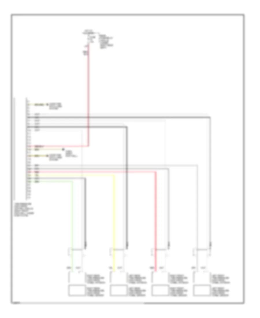
WARNING SYSTEMS Tire Pressure Monitoring Wiring Diagram for Mercedes-Benz S500 2005 List of elements for Tire Pressure Monitoring Wiring Diagram for Mercedes-Benz S500 2005: 18 Computer data lines system Fuse 10a Hot at all times L40 Left front tire pressure monitoring wheel antenna Left front tire pressure monitoring wheel sensor Left rear tire pressure monitoring wheel antenna Left rear tire pressure monitoring wheel sensor Module (under right rear seat) Nca Rear fuse/relay Red Right front tire pressure monitoring wheel antenna Right front tire pressure monitoring wheel sensor Right rear tire pressure monitoring wheel antenna Right rear tire pressure monitoring wheel sensor Tire pressure monitoring control module (right front footwell, under step plate) W36/2 (right footwell)
WIPER/WASHER Wiper/Washer Wiring Diagram for Mercedes-Benz S500 2005 List of elements for Wiper/Washer Wiring Diagram for Mercedes-Benz S500 2005: 42 15g 58d 87a Afl Can-b h Can-b l Circuit 15r relay (hot in run, acc & start) Combination switch Computer data lines system Exterior lamp switch Fuse 150a Fuse 15a Fuse 40a Headlamp cleaning switch Headlamp washer pump Heated washer hose Heated washer nozzles Hot at all times Hot in run or start Left front fuse/relay module (left rear of engine compt) Left front sam control module (in left fuse/ relay box, left rear corner of engine compt) Nca Nsl Overhead control panel control module (above rearview mirror) Park Pnk/red R/l sens sig Rain/light sensor (top center of dash) Red Right front sam control module (in right fuse/ relay box, left rear corner of engine compt) Sra Steering column module (left side of dash) Terminal block & fuse box (circuit 30 & 61) W2 (right side of eng compt) W9 (at left headlight) Windshield park heater relay Windshield washer pump Windshield wiper motor Wiper & washer switch Wiper on/off relay Wiper park position heater Wiper stage 1 & 2 relay