Diagram sections — 29 (54 total)
AIR CONDITIONING ANTI-LOCK BRAKES ANTI-THEFT COMPUTER DATA LINES COOLING FAN CRUISE CONTROL DEFOGGERS ELECTRONIC POWER STEERING ELECTRONIC SUSPENSION ENGINE PERFORMANCE EXTERIOR LIGHTS GROUND DISTRIBUTION HEADLIGHTS HORN INSTRUMENT CLUSTER INTERIOR LIGHTS POWER DISTRIBUTION POWER DOOR LOCKS POWER MIRRORS POWER SEATS POWER WINDOWS RADIO SHIFT INTERLOCKS STARTING/CHARGING SUPPLEMENTAL RESTRAINTS TRANSMISSION TRUNK, TAILGATE, FUEL DOOR WARNING SYSTEMS WIPER/WASHER
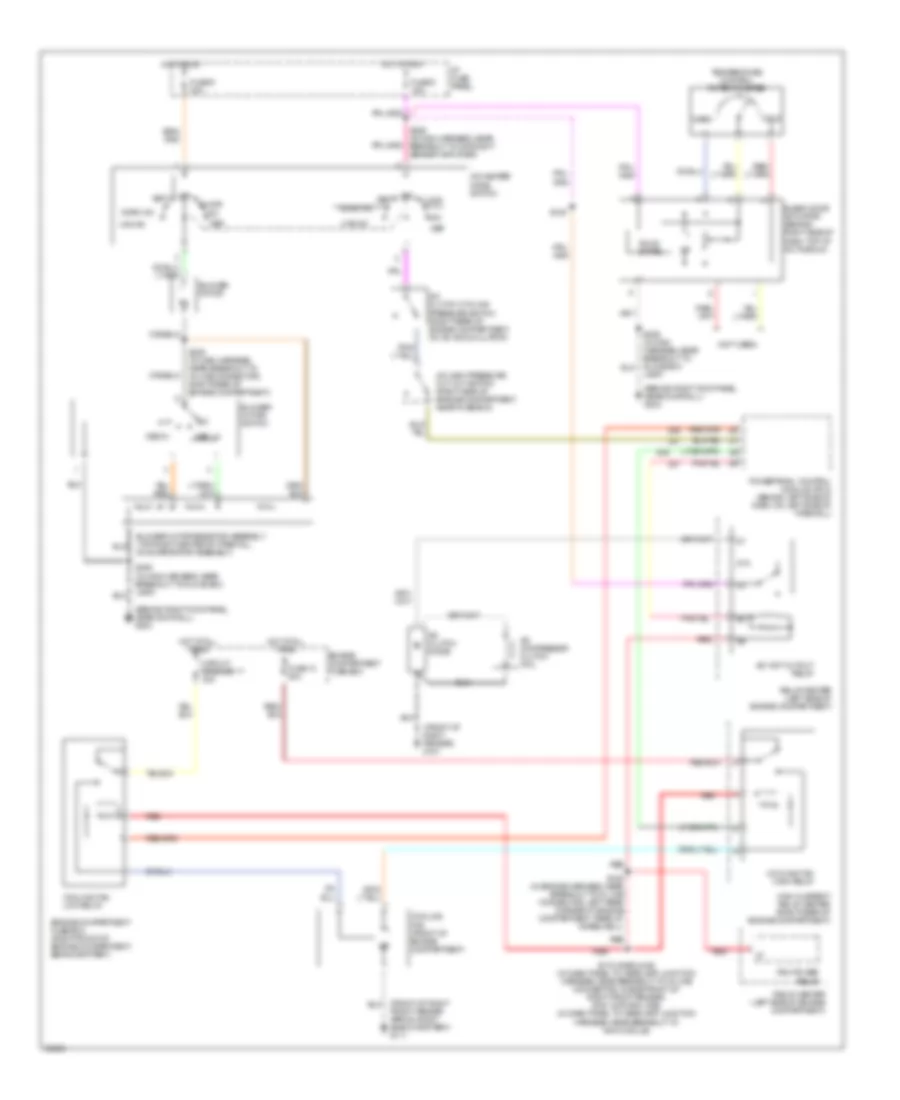
AIR CONDITIONING A/C Wiring Diagram, Auto A/C for Mercury Grand Marquis GS 1998 List of elements for A/C Wiring Diagram, Auto A/C for Mercury Grand Marquis GS 1998: 69 (behind right kick panel, near door sill) g203 (front of right fender) g101 (front of right front fender apron, right side of battery) g111 (in engine harness, near breakout to in-line connector, left rear corner of engine compartment, rear of wheelwell) s129 (in main harness, near breakout to day/night amplifier sensor) s226 (not used) 87a A/c clutch cycling pressure switch (right rear of engine compartment, on a/c accumulator) A/c clutch diode A/c clutch output A/c compressor clutch coil A/c high pressure cut out switch (right side of engine compartment, near fuse box) A/c wot cutout relay Amb temp sens input Ambient temperature sensor (center front of vehicle, on front of upper radiator support) Battery Blend door (cool) Blend door (heat) Blend door actuator (behind right side of dash, top of a/c plenum) Blend door pot gnd Blend dr feedback Blower motor Blower motor speed controller (top right center of firewall, on evaporator assembly) Blower mtr output Blower speed fback C227 C228 Circuit breaker 17 30a Computer data lines system Connector behind right side of dash) s204 Cooling fan (front of engine compartment) Cooling fan high relay Cooling fan low relay Data E/m converter Electronic automatic temperature control (eatc) module (behind center of dash) Engine compartment fuse box Engine compartment fuse box (right front of engine compartment, behind battery) Front panel illum Fuse 13 50a Fuse 15a Fuse 30a Ground High current relay center (right rear of engine compartment) Hot at all times Hot at all times Hot in run I/p fuse panel In car temp sens In-car temperature sensor (behind top center of dash) Inst illumination Instrument cluster (digital) Interior lights system Near door sill) g203 Pcm power relay Power Powertrain control module (pcm) (behind left side of dash, on left side of firewall) Red Reference voltage Relay center (left side of engine compartment) Relay signal S116 (gasoline) (in dash panel to headlamp junction harness, near breakout to in-line connector, inside front of right front fender) s197 (natural gas) (in dash panel to headlamp junction harness, near breakout to ngv module) S139 S206 (in main harness, near breakout to glove box lamp) S227 (in main harness, in breakout to lighting control module) S251 (in main harness, in breakout to eatc) Sensor ground Sun load sensor (top right side of dash, above glove box) Sunload sens input A/C Wiring Diagram, Manual A/C for Mercury Grand Marquis GS 1998 List of elements for A/C Wiring Diagram, Manual A/C for Mercury Grand Marquis GS 1998: 52 (behind right kick panel, near door sill) g203 (front of right fender) g101 (front of right front fender apron, right side of battery) g111 (not used) 87a A/c clutch cycling pressure switch (right rear of engine compartment, on a/c accumulator) A/c clutch diode A/c compressor clutch coil A/c high pressure cut out switch (right side of engine compartment, near fuse box) A/c wot cutout relay A/c-heater mode switch Blend door actuator (behind right side of dash, top of a/c plenum) Blower motor Blower motor resistor assembly (top right center of firewall, on evaporator assembly) Blower motor switch Circuit breaker 17 30a Cold Cooling fan (front of engine compartment) Cooling fan high relay Cooling fan low relay Def Engine compartment fuse box Engine compartment fuse box (right front of engine compartment, behind battery) Floor Fuse 13 50a Fuse 5 15a Fuse 9 30a High current relay center (right rear of engine compartment) Hot at all times Hot in run I/p fuse panel Lamp) Max a/c Med hi Med lo Mix Norm a/c Off Pcm power relay Powertrain control module (pcm) (behind left side of dash, on left side of firewall) Red Relay center (left side of engine compartment) S116 (gasoline) (in dash panel to headlamp junction harness, near breakout to in-line connector, inside front of right front fender) s197 (natural gas) (in dash panel to headlamp junction harness, near breakout to ngv module) S129 (in engine harness, near breakout to in line connector, left rear corner of engine compartment, rear of wheelwell) S139 S206 (in main harness, near breakout to glove box lamp) S226 (in main harness, near breakout to day/night sensor amplifier) S239 (in main harness, near breakout to in-line connector, right rear of engine compartment) Solid state Temperature control potentiometer Vent Warm
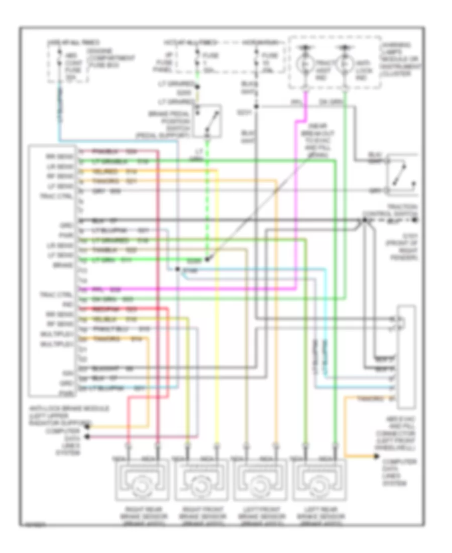
ANTI-LOCK BRAKES Anti-lock Brake Wiring Diagrams for Mercury Grand Marquis GS 1998 List of elements for Anti-lock Brake Wiring Diagrams for Mercury Grand Marquis GS 1998: 39 (near breakout to evac and fill conn) Abs cont fuse 30a Abs evac and fill connector (left front wheelwell) Anti- lock ind Anti-lock brake module (left upper radiator support) Brake Brake pedal position switch (pedal support) Computer data lines system Engine compartment fuse box Fuse 10a Fuse 15a G101 (front of right fender) Grd Hot at all times Hot in run I/p fuse panel Ign Ind Left front brake sensor (brake ass'y) Left rear brake sensor (brake ass'y) Lf sens Lr sens Multiplex Nca Pwr Red/pnk Rf sens Right front brake sensor (brake ass'y) Right rear brake sensor (brake ass'y) Rr sens S112 S146 S231 S265 S295 Trac ctrl Tract asst ind Traction control switch Warning lamps module or instrument cluster
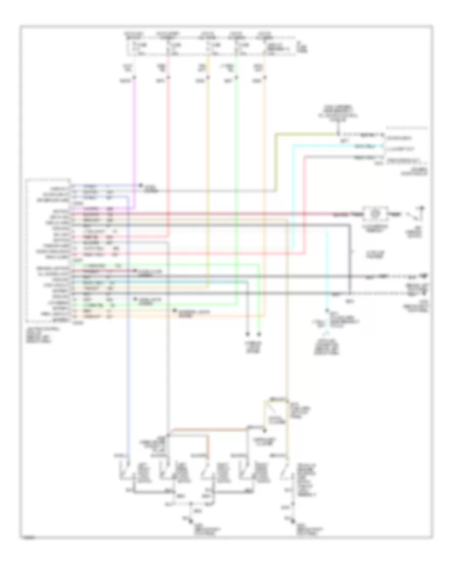
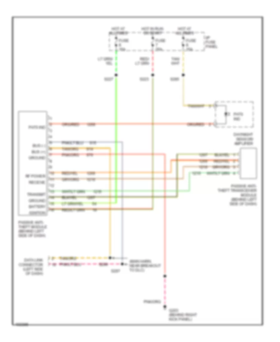
ANTI-THEFT Forced Entry Wiring Diagram for Mercury Grand Marquis GS 1998 List of elements for Forced Entry Wiring Diagram for Mercury Grand Marquis GS 1998: 68 (behind left kick panel) (main harness, near breakout to lighting control module) All doors lock Battery C2026 C2027 C2029 C518 Circuit breaker 12 18a Clockspring assembly Ctsy lps out Data link connector (behind left side of dash) Declid ajar Demand lighting Digital cluster Door ajar in Door ajar lp Door handle sw Door locks system Driver's door module Driver's dr ajar Exterior lights system Fuse 15a G200 G203 (behind right kick panel) Ground Headlights system Horn rly Horn system Hot at all times Hot in acc or run Hot in start or run I/p fuse panel Ignition Illum-ent out Instrument cluster Interior lights system Iso link Key warning switch Key-in ign Left front door latch switch Left rear door latch switch Lighting control module (behind left side of dash) Low beams Nca Panic alarm Panic signal out Park lamp out Pass dr ajar Right front door latch switch Right rear door latch switch S2009 S204 S207 S208 S227 S259 (near center of right "a" pillar) S262 S271 (in main harn, near breakout to dlc) S273 (main harn, left kick panel) S276 S277 S285 S403 S500 S600 Trunk lid release solenoid/ ajar switch (part of latch assembly) W/ police package Passive Anti-theft Wiring Diagram for Mercury Grand Marquis GS 1998 List of elements for Passive Anti-theft Wiring Diagram for Mercury Grand Marquis GS 1998: 25 (main harn, near breakout to dlc) Battery Bus (+) Bus (-) Data link connector (left side of dash) Day/night sensor/ amplifier Fuse 15a Fuse 25a G203 (behind right kick panel) Ground Hot at all times Hot in run or start I/p fuse panel Ignition Passive anti- theft module (behind left side of dash) Passive anti- theft transceiver module (behind left side of dash) Pats ind Receive Rf power S223 S227 S285 S296 S297 Transmit
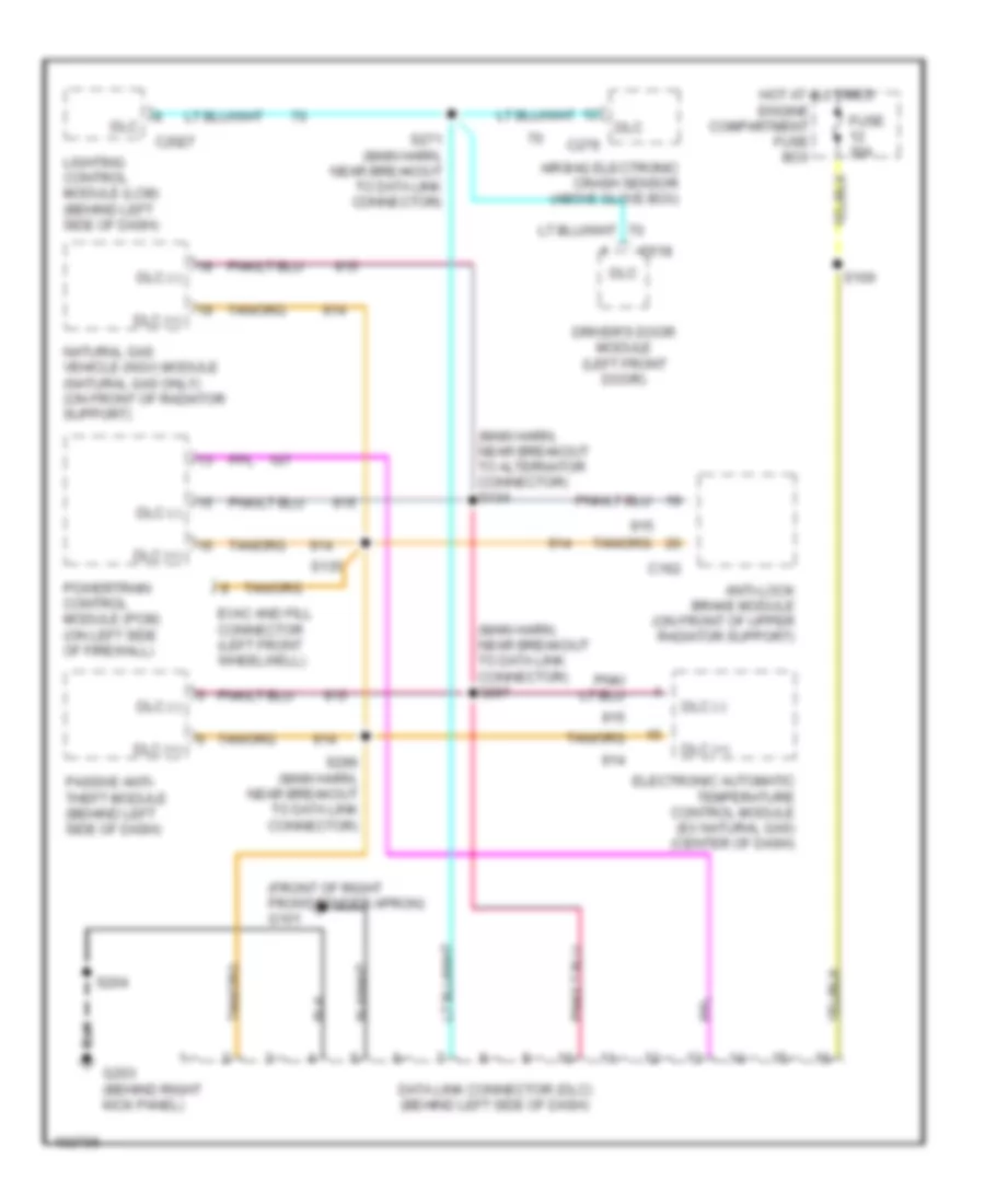
COMPUTER DATA LINES Computer Data Lines for Mercury Grand Marquis GS 1998 List of elements for Computer Data Lines for Mercury Grand Marquis GS 1998: 29 (front of right front fender apron) g101 (main harn, near breakout to alternator connector) s134 (main harn, near breakout to data link connector) s297 Air bag electronic crash sensor (above glove box) Anti-lock brake module (on front of upper radiator support) C162 C2027 C276 C518 Data link connector (dlc) (behind left side of dash) Dlc Dlc (+) Dlc (-) Driver's door module (left front door) Electronic automatic temperature control module (ex natural gas) (center of dash) Engine compartment fuse box Evac and fill connector (left front wheelwell) Fuse 30a G203 (behind right kick panel) Hot at all times Lighting control module (lcm) (behind left side of dash) Natural gas vehicle (ngv) module (natural gas only) (on front of radiator support) Passive anti- theft module (behind left side of dash) Powertrain control module (pcm) (on left side of firewall) S100 S135 S204 S271 (main harn, near breakout to data link connector) S296 (main harn, near breakout to data link connector)
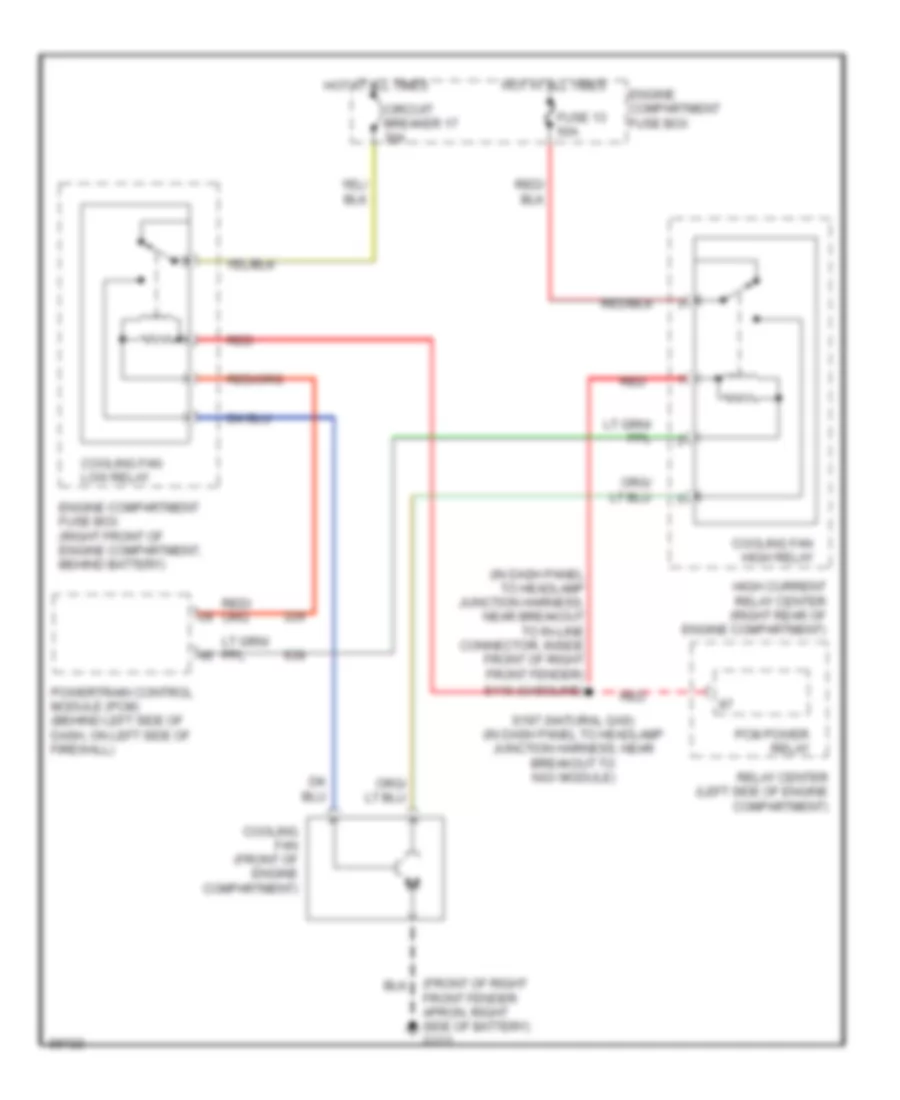
COOLING FAN Cooling Fan Wiring Diagram for Mercury Grand Marquis GS 1998 List of elements for Cooling Fan Wiring Diagram for Mercury Grand Marquis GS 1998: 17 (front of right front fender apron, right side of battery) g111 (in dash panel to headlamp junction harness, near breakout to in-line connector, inside front of right front fender) Circuit breaker 17 30a Cooling fan (front of engine compartment) Cooling fan high relay Cooling fan low relay Engine compartment fuse box Engine compartment fuse box (right front of engine compartment, behind battery) Fuse 13 50a High current relay center (right rear of engine compartment) Hot at all times Pcm power relay Powertrain control module (pcm) (behind left side of dash, on left side of firewall) Red Relay center (left side of engine compartment) S116 (gasoline) S197 (natural gas) (in dash panel to headlamp junction harness, near breakout to ngv module)
CRUISE CONTROL Cruise Control Wiring Diagram for Mercury Grand Marquis GS 1998 List of elements for Cruise Control Wiring Diagram for Mercury Grand Marquis GS 1998: 39 Brake pedal position (bpp) switch (top of brake pedal support) Brake press C238 C254 C283 Clock- spring assembly (top of steering column) Coast Digital cluster only Engine compart- ment fuse box Fuse 15a G203 (behind right kick panel) Ground Horn relay (in engine compt fuse box) Horn switches Hot at all times Hot in acc or run I/p fuse panel Ind output Instrument cluster Lighting control module (lcm) Nca Off Ohms Power Resume S105 S2009 S210 S243 (main harn, near breakout to multi- function switch) S265 Set/ accel Speed control deac switch (below brake fluid re- servoir) Speed control servo/amplifier assembly (left rear corner of engine compt) Speed control switch assembly (top of steering column) Stop lamp Switch rtn Switch sig Vehicle speed sensor (vss) (left rear side of trans) Vss input
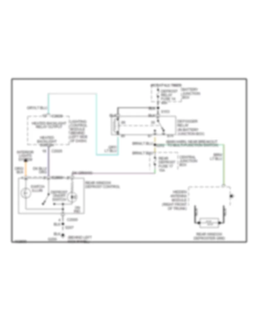
DEFOGGERS Defogger Wiring Diagram for Mercury Grand Marquis GS 1998 List of elements for Defogger Wiring Diagram for Mercury Grand Marquis GS 1998: 25 (behind left kick panel) (main harn, near breakout to multi-function switch) 87a Battery junction box C2000 C2026 Central junction box Defogger relay (in battery junction box) Defrost on/off switch Defrost relay fuse 14 40a G200 Heated backlight relay output Heated backlight switch Hidden antenna module (right front of trunk) Hot at all times Interior lights system Lighting control module (behind left side of dash) Nca On ind. Rear defrost fuse 17 10a Rear window defrost control Rear window defroster grid S153 S207 Switch illum.
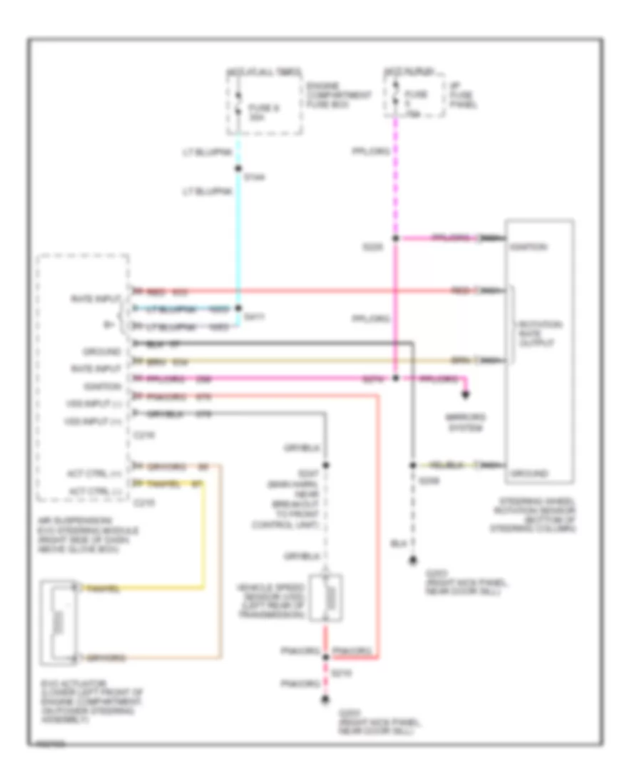
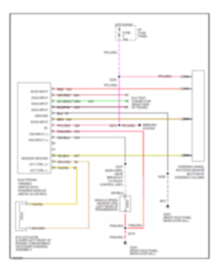
ELECTRONIC POWER STEERING Electronic Power Steering Wiring Diagram, with Air Suspension for Mercury Grand Marquis GS 1998 List of elements for Electronic Power Steering Wiring Diagram, with Air Suspension for Mercury Grand Marquis GS 1998: 31 Act ctrl (+) Act ctrl (-) Air suspension/ evo steering module (right side of dash, above glove box) C215 C216 Engine compartment fuse box Evo actuator (lower left front of engine compartment, on power steering assembly) Fuse 15a Fuse 8 30a G203 (right kick panel, near door sill) Ground Hot at all times Hot in run I/p fuse panel Ignition Mirrors system Nca Rate input Red Rotation rate output S144 S208 S210 S226 S247 (main harn, near breakout to front control unit) S274 S411 Steering wheel rotation sensor (bottom of steering column) Vehicle speed sensor (vss) (left rear of transmission) Vss input (+) Vss input (-) Electronic Power Steering Wiring Diagram, without Air Suspension for Mercury Grand Marquis GS 1998 List of elements for Electronic Power Steering Wiring Diagram, without Air Suspension for Mercury Grand Marquis GS 1998: 25 Act ctrl (+) Act ctrl (-) Diag input Electronic variable orifice (evo) steering module (above glove box) Evo actuator (lower left front of engine compartment, on power steering assembly) Evo test connector (right side of trunk) Fuse 15a G203 (right kick panel, near door sill) Ground Hot in run I/p fuse panel Mirrors system Nca Rate input Red S208 S210 S226 S247 (main harn, near breakout to front control unit) S274 Sensor ground Steering wheel rotation sensor (bottom of steering column) Vehicle speed sensor (vss) (left rear of transmission) Vss input (+) Vss input (-)
ELECTRONIC SUSPENSION Electronic Suspension Wiring Diagram for Mercury Grand Marquis GS 1998 List of elements for Electronic Suspension Wiring Diagram for Mercury Grand Marquis GS 1998: 59 (in main harn, near breakout to front control unit) s247 (near breakout to airbag diagnostic connector) (near breakout to right rear speaker) s431 Air suspension compressor motor and vent solenoid (below air cleaner assembly) Air suspension indicator Air suspension switch Air suspension test connector (left side of trunk) Air suspension/ evo steering module (above glove box) C215 C216 C251 c254 Comp rly Compressor relay D&h sens (-) Diag input Door open Driver's door module (in left front door) Engine compartment fuse box Evo act ctrl Evo actuator (on power steering assembly) Evo fdbk Fuse 15a Fuse 30a G101 (front of right fender) G203 (behind right kick panel) Ground Hot at all times Hot in run I/p fuse panel Ign on Instrument cluster Left rear air spring solenoid (top of left air spring) Lin ht sens Linear height sensor (left rear upper control arm) Lr sol ctrl Mirrors system Nca Pnk Red Right rear air spring solenoid (top of right air spring) Rr sol ctrl S105 S112 S144 S208 S210 S226 S268 (near breakout to airbag diagnostic connector) S274 S300 S406 S411 Serv sw St whl rot Steering wheel rotation sensor (base of steering column) Vehicle speed sensor (left rear of transmission) Vent sol Vss in Warn lp out
ENGINE PERFORMANCE
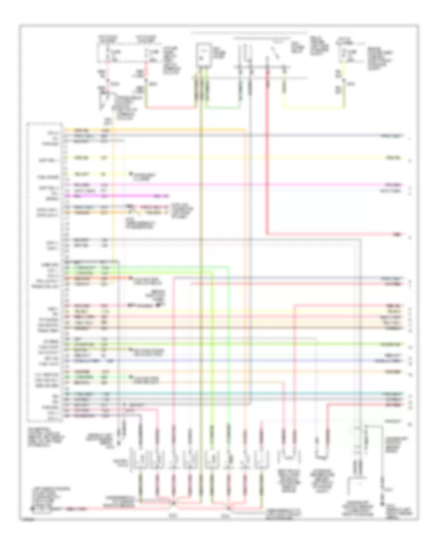
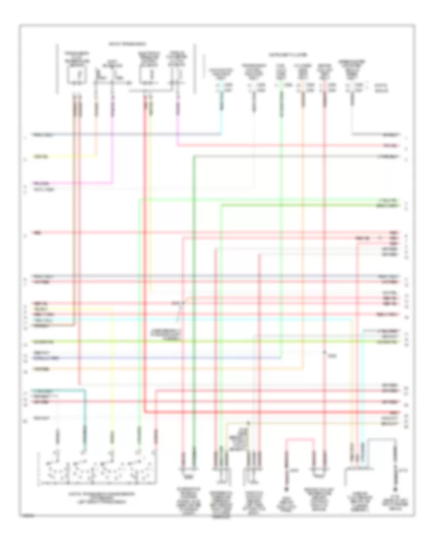
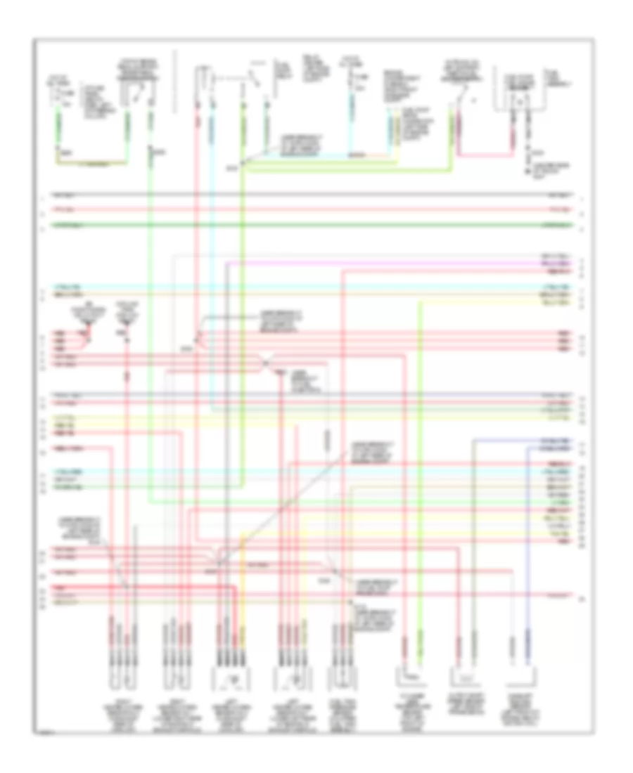
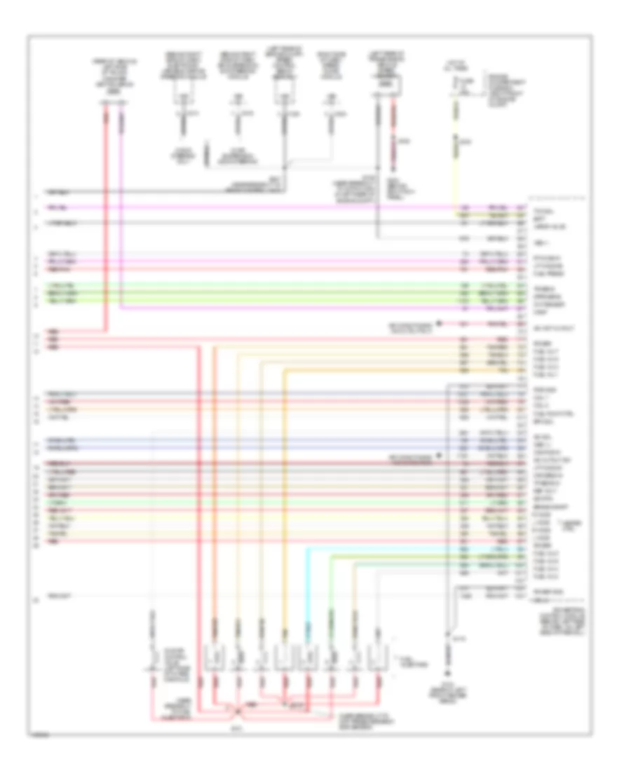
4.6L 4.6L, Engine Performance Wiring Diagrams (1 of 4) for Mercury Grand Marquis GS 1998 List of elements for 4.6L, Engine Performance Wiring Diagrams (1 of 4) for Mercury Grand Marquis GS 1998: 73 (behind right kick panel) g203 (left side of engine, on left side of engine coil) radio noise capacitor (near breakout to 4-pin conn at right front fender) (near breakout to camshaft position sensor) (rear of left front fender apron) A/c cutout Air conditioning (a/c cutout sw) Case gnd Ckp (+) Ckp (-) Coil 1 Coil 3 Coil 5 Coil 6 Cooling fans (fan high rly) Cooling fans (fan low relay) Crankshaft position sensor (lower right front of engine) Crankshaft position sensor shield Cyl temp ind Data link (+) Data link (-) Data link connector (left side of dash) Ect ind Egr vac reg Egr vacuum regulator solenoid (top center rear of engine) Engine compartment fuse box (right front of engine compt) Eprom Fan high rly Fan low rly Fuel flow Fuel gauge Fuel pump Fuse 15a Fuse 25a Fuse 30a G104 G104 (rear of left front fender apron) Hot at all times Hot in run or start I/p fuse panel (below dash, left of steering column) Iat sens Ignition coils Instrument cluster Intake air temperature sensor (left front of engine compt) Maf sig rtn Mil Nca Pcm power diode Pcm power relay Powertrain control module (behind left side of dash, on left side of firewall) Pwr gnd Red Relay center (left side of engine compt) Rt ho2s #2 S100 S101 S103 S119 S134 S135 (near breakout to generator) S151 S223 S276 Shft sol 1 Shft sol 2 Tcil Tr1 Tr2 Tr4 Trans ctrl sw Trans temp Transmission control switch (bottom of steering column) Vss (-) 4.6L, Engine Performance Wiring Diagrams (2 of 4) for Mercury Grand Marquis GS 1998 List of elements for 4.6L, Engine Performance Wiring Diagrams (2 of 4) for Mercury Grand Marquis GS 1998: 36 (near breakout to engine compt fuse box) (speedometer/ odometer) vehicle speed input 4r7ow transmission Analog C250 C251 C255 C256 Cylinder head temp input Differential pressure feedback egr sensor (right side of intake manifold) Digital Digital transmission range sensor (dtr sensor) (left side of transmission) Electronic pressure control solenoid Engine coolant temp input Engine coolant temperature sensor (top right front of engine) Evaporative emission canister purge valve (rear center of engine compt) Fuel flow rate input G104 (rear of left front fender apron) G203 (behind right kick panel) Instrument cluster Malfunction indicator input Mass air flow sensor (behind air cleaner assembly) R n Red S105 S119 S126 (near breakout to right htd oxy sensor 1) S153 S222 Shift solenoids Ss1 Ss2 Throttle position sensor (left side of throttle body) Torque converter clutch solenoid Transmission control indicator input Transmission fluid temperature sensor 4.6L, Engine Performance Wiring Diagrams (3 of 4) for Mercury Grand Marquis GS 1998 List of elements for 4.6L, Engine Performance Wiring Diagrams (3 of 4) for Mercury Grand Marquis GS 1998: 41 (center rear of trunk) g407 (in trunk, on left support) inertia fuel shutoff switch (near breakout to 16-pin conn at left rear of engine compt) (near breakout to 4-pin conn at left rear of engine compt) (near breakout to 8-pin conn at left rear of engine compt) (near breakout to 8-pin conn at left rear of engine compt) s148 (near breakout to fuel injector 8) (near breakout to fuel pump prime conn) (top of brake pedal support) brake pedal position switch Air conditioning (a/c cutout relay) Camshaft position sensor (left front of engine, below ignition coil) Cooling fans (fan low relay) Cylinder head temperature sensor (top left front of engine) Engine compartment fuse box (right front of engine compt) Fuel pump prime connector (left sdie of engine compt) Fuel pump relay Fuel pump/ fuel gauge sender Fuel tank assembly Fuel tank pressure sensor (on upper fuel tank assembly) Fuse 15a Fuse 20a Hot at all times I/p fuse panel (below dash, left of steering column) Left heated oxygen sensor no 1 (lower left rear of engine, in exhaust manifold) Left heated oxygen sensor no 2 (in exhaust, rear of catalyst) Nca Output shaft speed sensor (left side of transmission) Red Red/pnk Relay center (left side of engine compt) Right heated oxygen sensor no 1 (lower right rear of engine, in exhaust manifold) Right heated oxygen sensor no 2 (in exhaust, rear of catalyst) S115 (near breakout to 16-pin conn at left rear of engine compt) S123 S124 S125 S129 S130 S147 S265 S402 4.6L, Engine Performance Wiring Diagrams (4 of 4) for Mercury Grand Marquis GS 1998 List of elements for 4.6L, Engine Performance Wiring Diagrams (4 of 4) for Mercury Grand Marquis GS 1998: 76 (behind right side of dash) air suspension/ evo steering module (behind right side of dash) electronic variable orifice steering module (left rear of engine compt) speed control servo assembly (left rear of transmission) vehicle speed sensor (near breakout to diff press feedback egr sensor) (near breakout to fuel injector 8) (rear of vehicle, left side of trunk) canister vent solenoid (right side of dash) speed chime module A/c cutout sw A/c wot cutout Air conditioning (a/c cutout rly) Air conditioning (a/c cutout sw) Batt Brake on/off C204 C214 C216 C234 Cam pos in Canp Cht sensor Coil 2 Coil 7 Coil 8 Dpfe sens Engine compartment fuse box (right front of engine compt) Epc sol Fuel inj 1 Fuel inj 2 Fuel inj 3 Fuel inj 4 Fuel inj 5 Fuel inj 6 Fuel inj 7 Fuel inj 8 Fuel injectors Fuel press Fuel pump ctrl Fuse 30a G104 (rear of left front fender apron) G203 (behind right kick panel) Heater ctrl Hot at all times Iac sol Idle air control valve (left side of intake manifold) L ho2s Lft ho2s #1 Lft ho2s #2 Maf sens in Oss (+) Power Power gnd Powertrain control module (behind left side of dash, on left side of firewall) Pwr gnd R ho2s Red Red/pnk Ref volt Rt ho2s #1 S105 S109 (near breakout to 16-pin conn at left rear of engine compt) S119 S131 S143 S247 (near breakout to front control unit) Sig rtn Tan Tan/red Tcc sol Tp sens in Tr sens Vapor valve Vss (+) Vss (-) W/ air suspension & evo steering W/ evo steering only
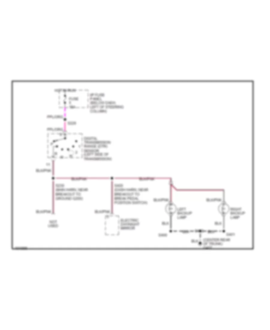
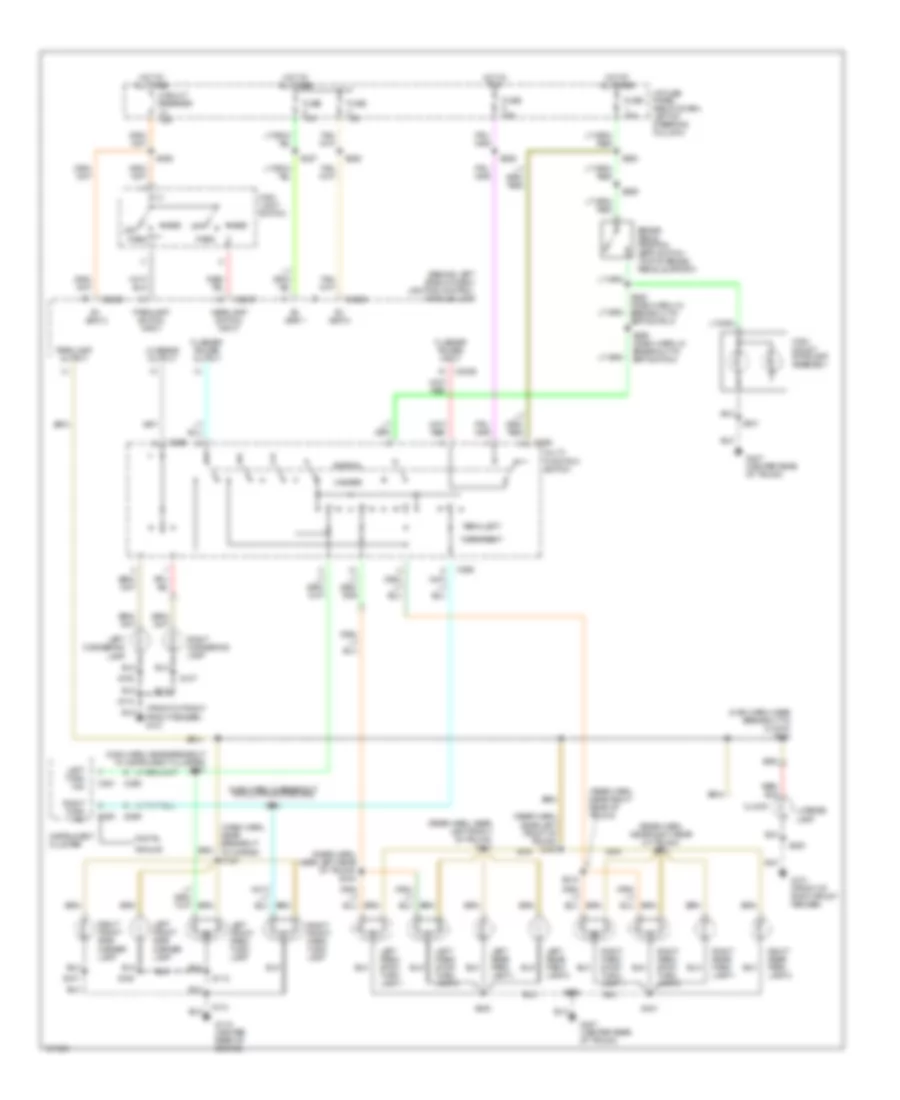
EXTERIOR LIGHTS Back-up Lamps Wiring Diagram for Mercury Grand Marquis GS 1998 List of elements for Back-up Lamps Wiring Diagram for Mercury Grand Marquis GS 1998: 15 (center rear of trunk) g407 Digital transmission range (dtr) sensor (left side of transmission) Electric day/night mirror Fuse 15a Hot in run I/p fuse panel (below dash, left of steering column) Left backup lamp Not used Right backup lamp S226 S230 (main harn, near breakout to ground g200) S400 S401 S402 S420 (dash harn, near breakout to break pedal position switch) Exterior Lamps Wiring Diagram for Mercury Grand Marquis GS 1998 List of elements for Exterior Lamps Wiring Diagram for Mercury Grand Marquis GS 1998: 86 (behind left side of dash) lighting control module (lcm) (dash harn, near breakout to horns) s120 (front of right front fender) g101 (main harn, in breakout to multi-function sw) (main harn, near breakout to clock) s242 (main harn, near breakout to instrument cluster) s257 (rear harn, near left front of trunk) s409 (rear harn, near left front of trunk) s413 (rear harn, near left rear of trunk) s444 (rear harn, near right rear of trunk) (rear harn, near right rear of trunk) s414 Analog B+ vbat 1 B+ vbat 2 B+ vbat 3 Brake pedal position (bpp) switch (top of brake pedal support) C2027 C2029 C250 C251 C256 C268 C269 Circuit breaker 18a Clock Digital Flasher power input Flasher power output Fuse 15a G101 (front of right front fender) G115 (center rear of engine) G407 (center rear of trunk) Hazard Head Headlamp switch input High mount stoplamp assembly Hot at all times Hot in run I/p fuse panel (below dash, left of steering column) Instrument cluster Left cornering lamp Left front park/ turn lamp Left front side marker lamp Left park/ stop/ turn lamp 1 Left park/ stop/ turn lamp 2 Left rear park lamp 1 Left rear park lamp 2 Left turn ind License lamp Lo beams output Main light switch Multi- function switch Normal Off Park Parklamp output Parklamp switch input Right cornering lamp Right front park/ turn lamp Right front side marker lamp Right park/ stop/ turn lamp 1 Right park/ stop/ turn lamp 2 Right rear park lamp 1 Right rear park lamp 2 Right turn ind S107 S108 S112 S113 S226 S227 S244 S258 (dash harn, in breakout to bpp switch) S262 S263 S265 S265 (dash harn, in breakout to bpp switch) S285 S301 S400 S401 S402 S415 S420 Turn left Turn right
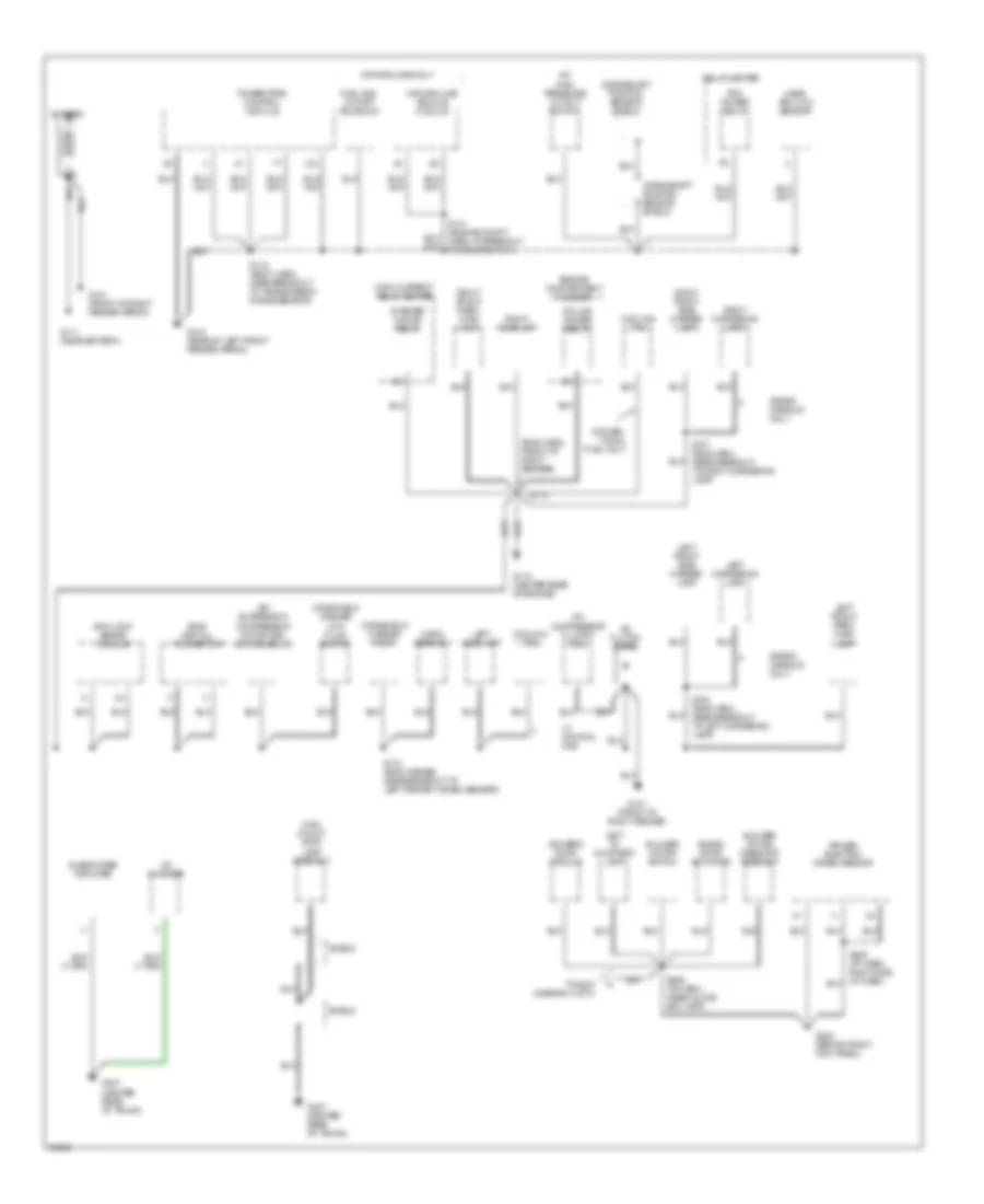
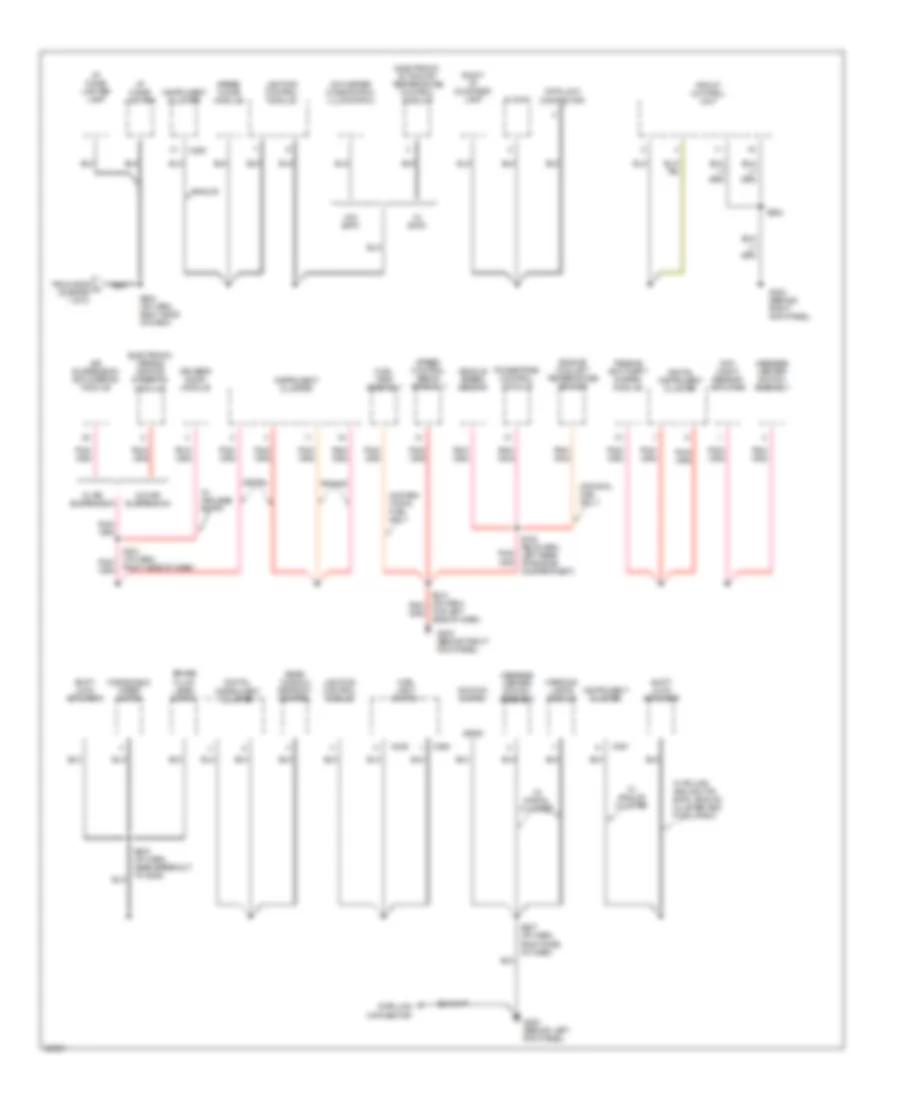
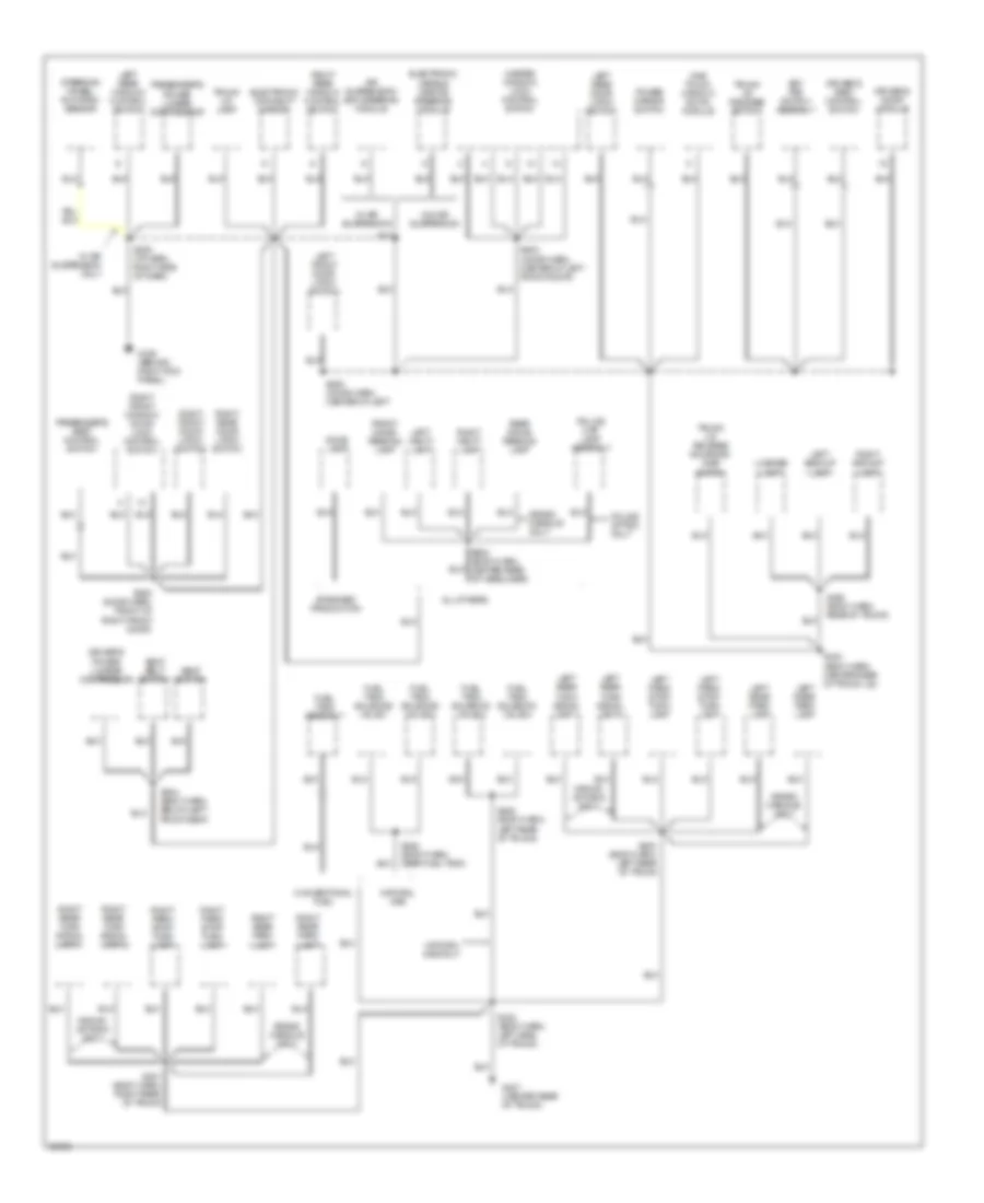
GROUND DISTRIBUTION Ground Distribution Wiring Diagram (1 of 3) for Mercury Grand Marquis GS 1998 List of elements for Ground Distribution Wiring Diagram (1 of 3) for Mercury Grand Marquis GS 1998: 60 (eng harn, front of right fender) A/c clutch diode A/c compressor cluitch coil A/c high pressure cutout switch Air suspension compressor motor and vent solenoid Air-bag electric crash sensor Anti-lock brake module Battery Blend door actuator Blower motor resistor assembly Blower motor switch Cd changer Conven- tional fuel only Cooling fan Crankshaft position sensor shield Driver's door module Engine compartment fuse box Evac and fill connector Fuel rail cutoff solenoid G101 (front of right fender apron) G101 (front of right fender) G104 (rear of left front fender apron) G111 (near battery) G115 (center rear of engine) G203 (behind right kick panel) G407 (center rear of trunk) Grand marquis only High current relay center High mount stop lamp assembly Horn assembly Left cornering lamp Left front park/ turn lamp Left front side marker lamp Left headlamp Left i/p courtesy lamp Mass air flow sensor Natural gas only Natural gas vehicle module Pcm power relay Police power relay Powertrain control module Relay center Right cornering lamp Right front park/ turn lamp Right front side marker lamp Right headlamp S107 (eng harn, near breakout to right cornering lamp) S108 (eng harn, near breakout to left cornering lamp) S112 (eng harnes, near breakout to left primary crash sensor) S113 S119 (body harn, near breakout to transmission range sensor) S141 (engine compt harn, in breakout to ground g101) S206 (i/p harn, (near glove box lamp) Shield Starter motor relay Subwoofer amplifier To s204 (diagram 2 of 3) W/ natural gas Windshield washer low fluid switch Windshield washer pump Ground Distribution Wiring Diagram (2 of 3) for Mercury Grand Marquis GS 1998 List of elements for Ground Distribution Wiring Diagram (2 of 3) for Mercury Grand Marquis GS 1998: 56 A/c-heater mode switch illumination Air suspension/ evo stering module Analog Brake fluid level switch C249 C250 C251 C262 Clock Conven- tional fuel only Data link connector Day/ night sensor/ amplifier Digital Digital instrument cluster Driver's door module Electronic automotic temperature control module Electronic varible orifice steering module Engine coolant temperature sender From s206 a (diagram 1 of 3) Front control unit Fuel tank assembly G200 (behind left kick panel) G203 (behind right kick panel) I/p cigar lighter I/p cigar lighter lamp Ignition switch Instrument cluster Lighting control module Main light switch Message center switch assembly Natural gas only Passive anti-theft system module Powertrain control module Rear window defrost control Right i/p courtesy lamp S105 (eng harn, left rear of engine compartment) S203 (i/p harn, near breakout to g200) S204 (i/p harn, right side of dash) S207 (i/p harn, right side of dash) S214 (i/p harn, right side of dash) S284 Shift lock actuator Speed chime module Speed control servo assembly Top left side of dash) Vehicle speed sensor W/ air suspension W/ analog cluster W/ digital cluster W/ eatc W/ keyless entry W/ police and ngv or eatc, analog cluster and p100l radio W/o air suspension W/o eatc Warning lamps module Windshield wiper motor Ground Distribution Wiring Diagram (3 of 3) for Mercury Grand Marquis GS 1998 List of elements for Ground Distribution Wiring Diagram (3 of 3) for Mercury Grand Marquis GS 1998: 73 Air suspension/ evo steering module All others Conventional fuel Crown victoria only Dome lamp Driver's power lumbar compressor Driver's seat control switch Driver,s door module Electronic day/night mirror Electronic varible orifice steering module Front dome/ reading lamp Fuel tank assembly Fuel tank solenoid valve 1 Fuel tank solenoid valve 2 Fuel tank solenoid valve 3 Fuel tank solenoid valve 4 G203 (behind right kick panel) G407 (center rear of trunk) Grand marquis only Key pad switch assembly Left backup lamp Left front door latch switch Left park/ stop/ turn lamp Left rear door latch switch Left rear park lamp Left rear turn signal lamp 1 Left rear turn signal lamp 2 Left rear window control switch Left vanity lamp License lamp Master window/ lock control switch Natural gas Natural gas only One touch window down module Passenger's power lumbar compressor Passenger's seat control switch Police map lamp assembly Police option only Power mirror switch Rear dome/ reading lamp Right backup lamp Right front door latch switch Right front window/ door lock control switch Right park/ stop/ turn lamp Right rear door latch switch Right rear park lamp Right rear turn signal lamp 1 Right rear turn signal lamp 2 Right rear window control switch Right vanity lamp S208 (i/p harn, right side of dash) S304 (body harn, below left front seat) S400 (body harn, left rear of trunk S401 (body harn, right rear of trunk S402 (body harn, left side of trunk) S403 (body harn, center rear of trunk lid) S405 (body harn, left rear of trunk) S420 (body harn, rear of trunk) S428 (body harn, near fuel tank) S500 (door harn, center of left S503 (door harn, center of left front door) S600 (door harn, front of right front door) S902 (body harn, center rear of headliner) Seat belt switch Seat switch Standard production Steering wheel rotation sensor Trunk lid lamp Trunk lid release solenoid/ ajar switch Trunk lid release switch W/ air suspension W/ air suspension only W/o air suspension
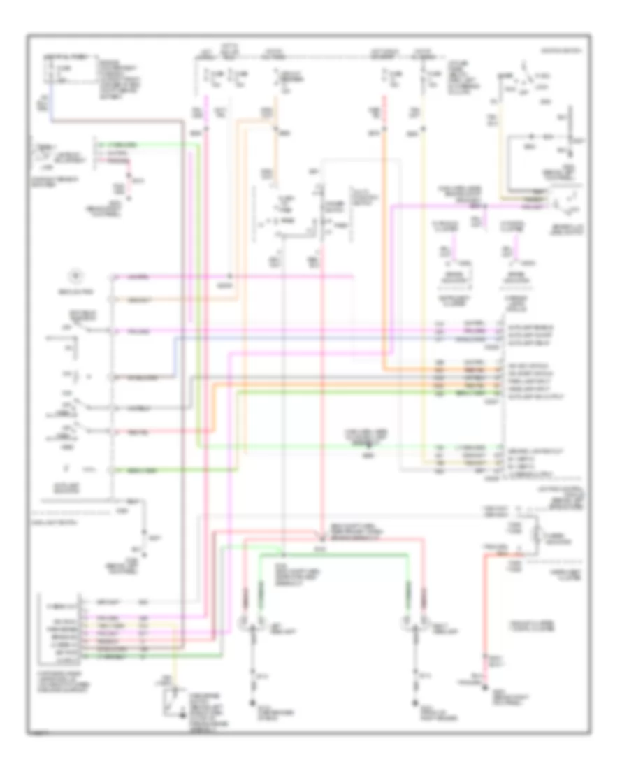
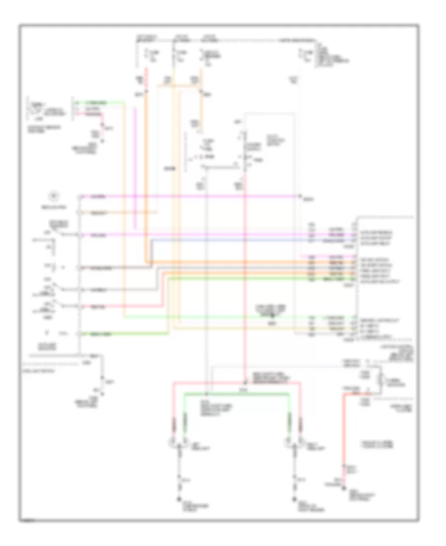
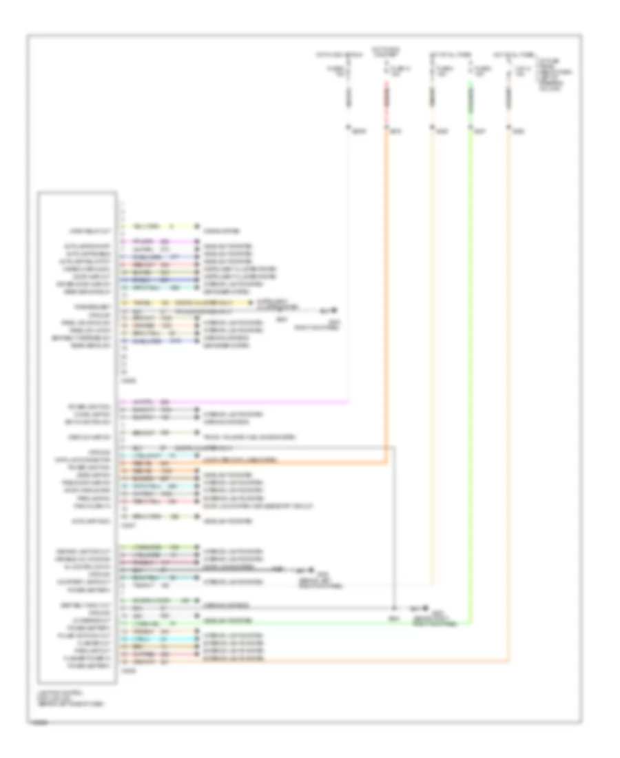
HEADLIGHTS Headlamps Wiring Diagram, with DRL for Mercury Grand Marquis GS 1998 List of elements for Headlamps Wiring Diagram, with DRL for Mercury Grand Marquis GS 1998: 96 "lamps on" adjustment (eng compt harn, near primary crash sensor breakout) (main harn, near engine compt grommet) s209 (main harn, near glove box lamp breakout) * analog cluster ** digital cluster **c255 **c256 *c250 Acc Aut0lamp enable Autolamp delay Autolamp ind output Autolamp indicator Autolamp on/off B+ (vbat 2) B+ (vbat 3) Backlighting Bat pwr Brake fluid level switch Brake ind Brake indicator C2004 C2026 C2027 C2029 C250 C262 Circuit breaker 18a Day/night sensor amplifier Daytime running lamps module (on front of upper radiator support) Demand lighting out Dimmer switch Early Engine compartment fuse box (in right front corner of eng compt, behind battery) Exit delay rheostat Flash -to- pass Fuse 15a Fuse 20a G101 (front of right fender) G115 (center rear of eng) G200 (behind left kick panel) G203 (behind right kick panel) Gnd Head Headlamp input Hi beam indicator Hi beam out Hi input Hot at all times Hot in acc or run Hot in run Hot in run or start I/p fuse panel (below dash, left of steering column) Ign (run) Ign acc or run Ign start or run Ignition switch Instrument cluster Late Left headlamp Lighting control module (behind left side of dash) Lo beam in Lo beams output Lock Low Main light switch Max Min Multi- function switch Off Park Park brake Park brake switch (behind left side of dash, on top of parking brake assembly) Park lamp input Pass Right headlamp Run S112 S113 S138 (eng compt harn, near horn assy breakout) S140 S2009 S203 S204 * S207 S210 S210 ** S226 S262 S276 S285 S290 Start W/ analog cluster W/ digital cluster Warning lamps module Headlamps Wiring Diagram, without DRL for Mercury Grand Marquis GS 1998 List of elements for Headlamps Wiring Diagram, without DRL for Mercury Grand Marquis GS 1998: 67 "lamps on" adjustment (eng compt harn, near primary crash sensor breakout) (main harn, near glove box lamp breakout) * analog cluster ** digital cluster **c255 **c256 *c250 Aut0lamp enable Autolamp delay Autolamp ind output Autolamp indicator Autolamp on/off B+ (vbat 2) B+ (vbat 3) Backlighting C2026 C2027 C2029 C262 Circuit breaker 18a Day/night sensor amplifier Demand lighting out Dimmer switch Early Exit delay rheostat Flash -to- pass Fuse 15a G101 (front of right fender) G115 (center rear of eng) G200 (behind left kick panel) G203 (behind right kick panel) Head Headlamp input Hi beam indicator Hot at all times Hot in acc or run Hot in run or start I/p fuse panel (below dash left of steering column) Ign acc or run Ign start or run Instrument cluster Late Left headlamp Lighting control module (behind left side of dash) Lo beams output Main light switch Max Min Multi- function switch Off Park Park lamp input Pass Right headlamp S112 S113 S138 (eng compt harn, near horn assy breakout) S140 S2009 S204 * S207 S210 S210 ** S262 S276 S285 S290 Lighting Control Module Wiring Diagram for Mercury Grand Marquis GS 1998 List of elements for Lighting Control Module Wiring Diagram for Mercury Grand Marquis GS 1998: 75 (behind left right kick panel) (behind right right kick panel) (digital cluster only) (police package only) All doors lock in Autolamp delay pot Autolamp enable Autolamp indic Autolamps on/off C.b. 12 18a C2026 C2027 C2029 Computer data lines system Courtesy lamps out Data link connector Decklid ajar sw Defogger system Demand lighting out Dome lamp sw Door ajar out Door handle sws Door lock system (keyless entry circuit) Door locks system Driver door ajar sw Exterior lights system Flasher out Flasher power in Fuse 13 15a Fuse 4 15a Fuse 6 15a Fuse 8 15a G200 G203 G203 (right kick panel) Ground Hazard warn indic Headlamp sw Headlights system Horn relay out Horns system Hot at all times Hot in acc or run Hot in run or start I/p fuse panel (below dash, left of steering column) Instrument cluster system Interior lights system Key-in-ignition sw Lighting control module (lcm) (behind left side of dash) Low beams out Panel dim down sw Panel dim up sw Panic alarm in Parklamp out Parklamp sw Pass door ajar sw Power (battery) Power (ignition) Pulse width dim out Rear defog relay Rear defog sw S200 S2009 S204 S207 S227 S262 S276 S285 Seat belt fastened sw Seat belt indic out Tone request Trunk, tailgate, fuel doors system Variable volt dimming Warning systems
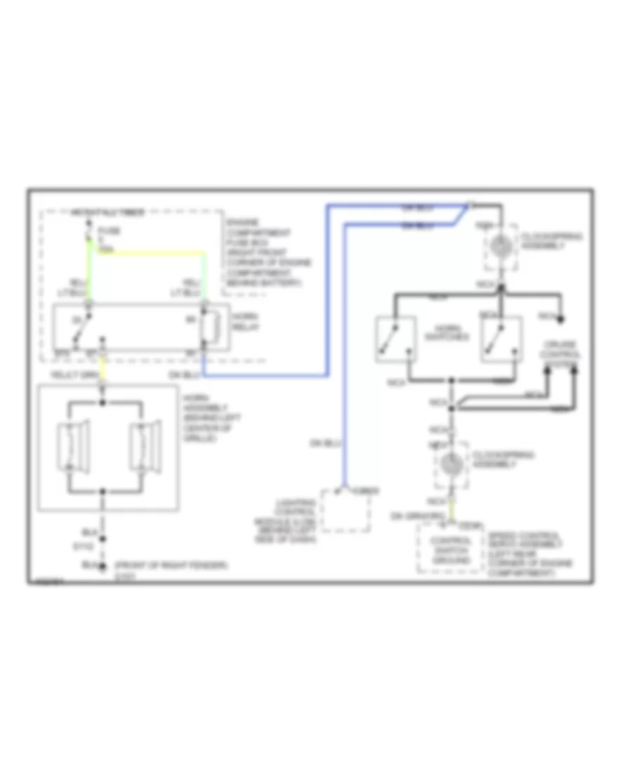
HORN Horn Wiring Diagram for Mercury Grand Marquis GS 1998 List of elements for Horn Wiring Diagram for Mercury Grand Marquis GS 1998: 18 (front of right fender) g101 87a C2026 C234 Clockspring assembly Control switch ground Cruise control system Engine compartment fuse box (right front corner of engine compartment, behind battery) Fuse 15a Horn Horn assembly (behind left center of grille) Horn relay Hot at all times Lighting control module (lcm) (behind left side of dash) Nca S112 Speed control servo assembly (left rear corner of engine compartment) Switches
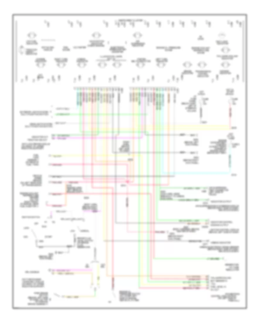
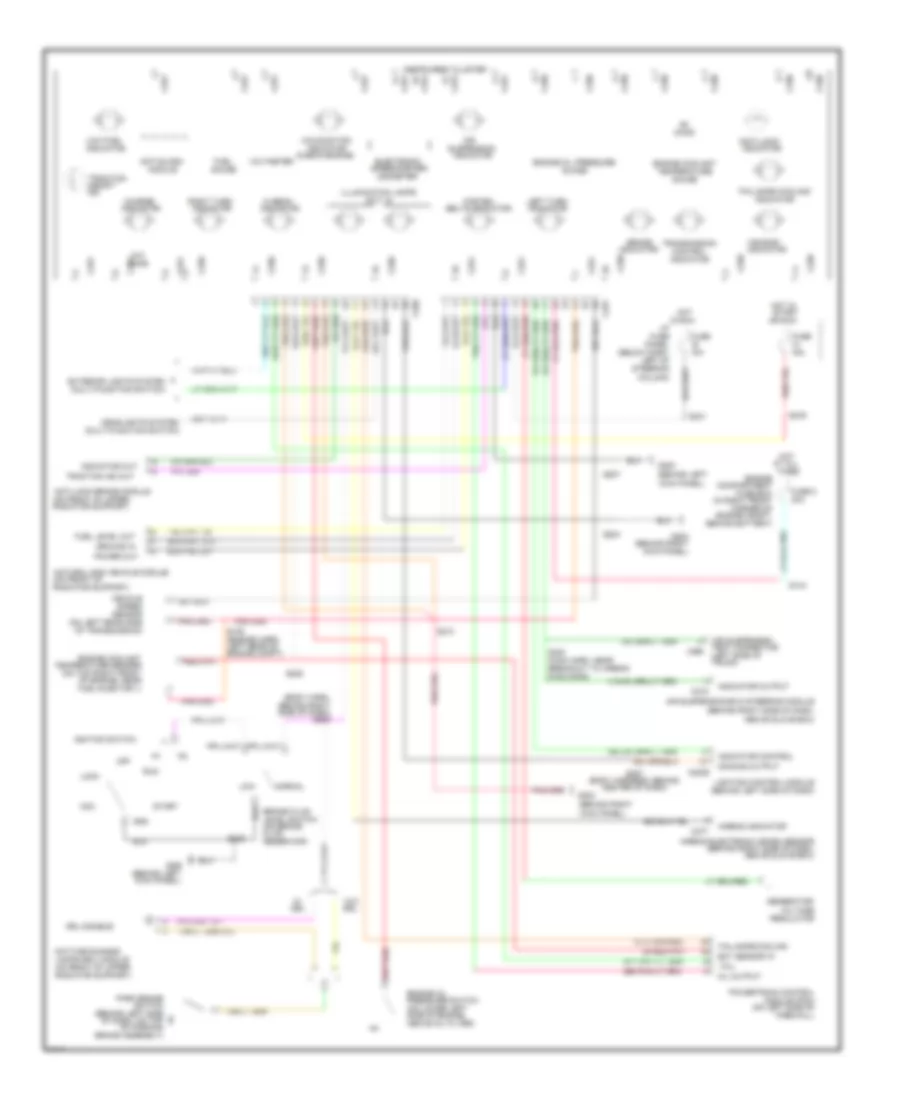
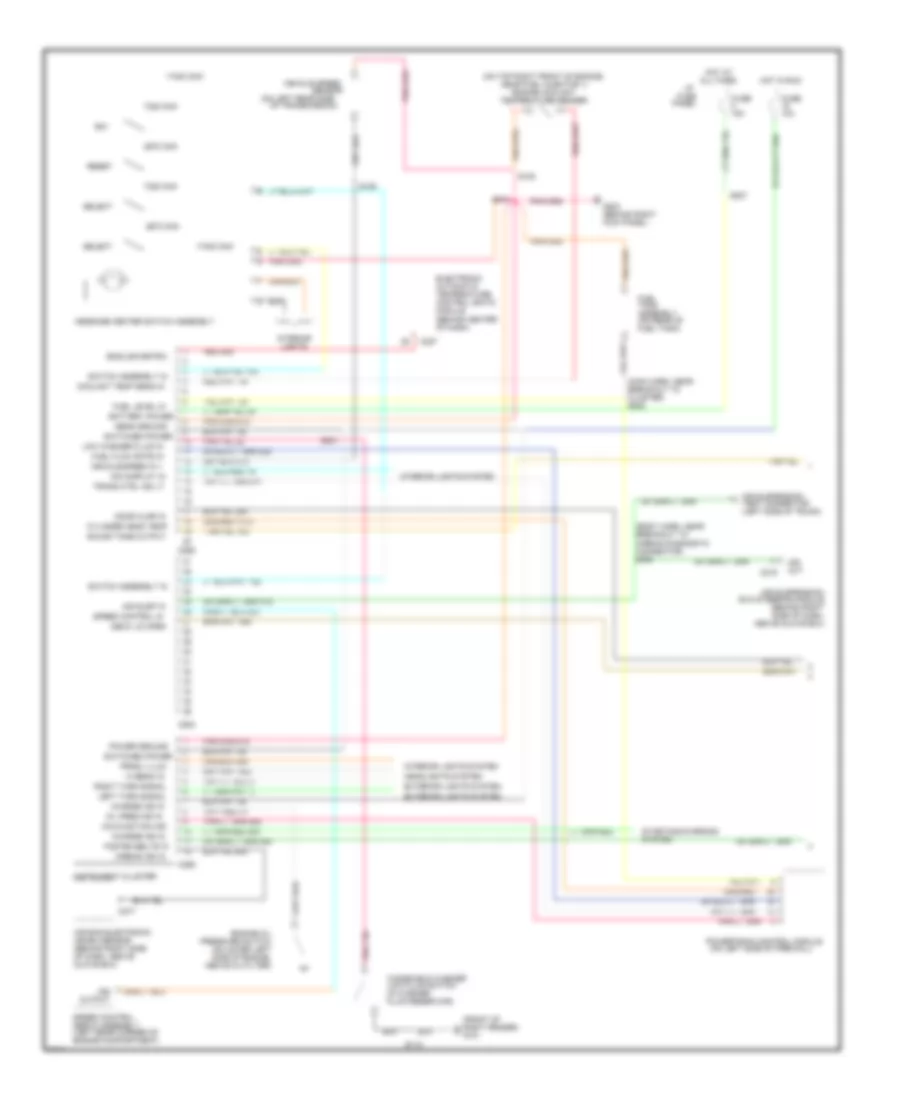
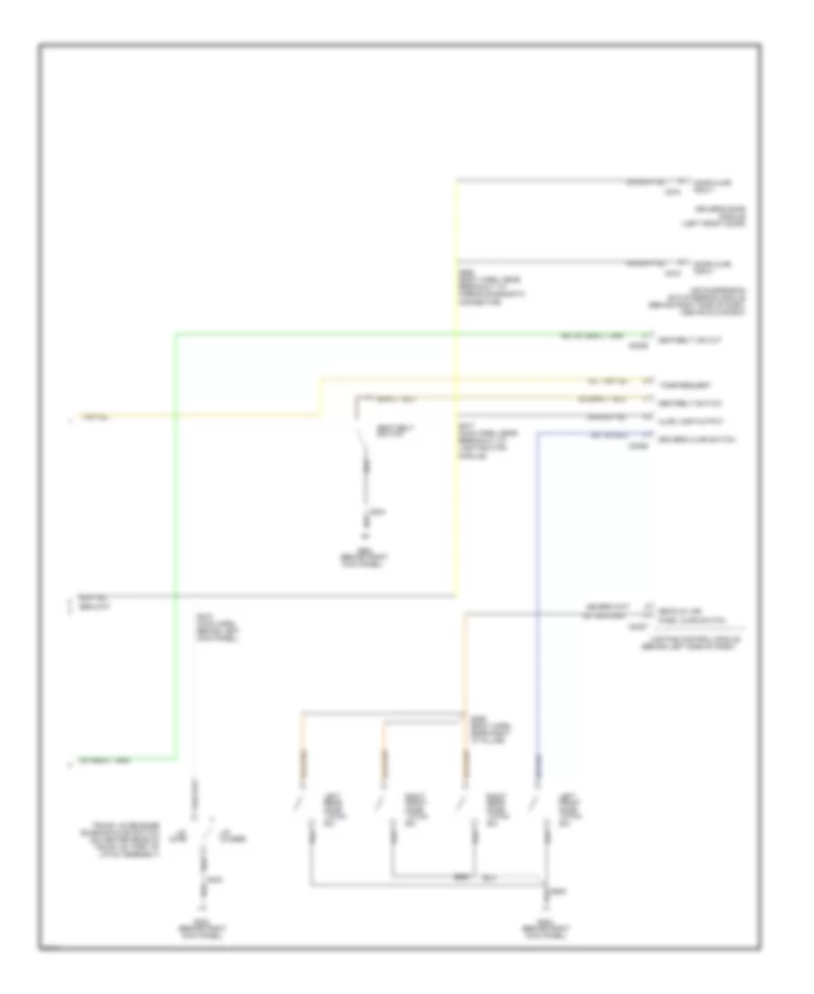
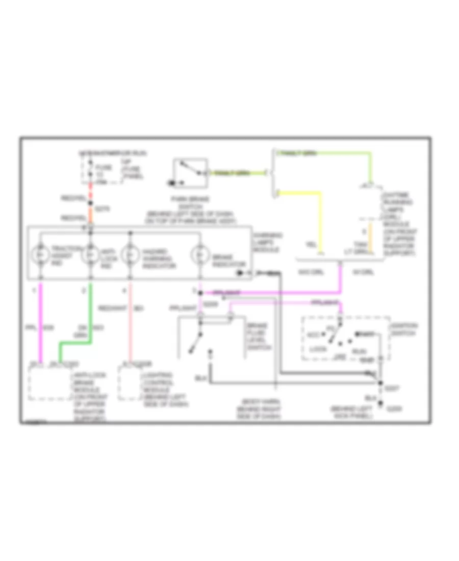
INSTRUMENT CLUSTER Analog Cluster Wiring Diagram for Mercury Grand Marquis GS 1998 List of elements for Analog Cluster Wiring Diagram for Mercury Grand Marquis GS 1998: 178 "air bag" "anti-lock" "fail-safe cooling" "traction (behind left (behind left side (behind left side of dash) (behind right (behind right side of dash, (below dash, (body harn, (body harness, behind (check engine) (dash (engine harn, (in right front (left side of (main harn, near (multi-function switch) (on brake (on front of upper (on left rear side (on left side of (on lower left (on rear of (on top (qty. 6) 10a 15a 30a Above glove box) Above oil filter) Acc Air Air suspension Air suspension/evo steering module Airbag electronic crash sensor Airbag indicator Anti-lock brake module Anti-slosh Assembly Assist" At all Behind Behind battery) Behind right Belts indicator Brake Brake assembly) Brake fluid Breakout to airbag C2029 C215 C250 C251 C277 C459 Center of dash) Charge Column) Compartment Control Control module (pcm) Corner of Daytime running Diag conn) Dimming output Drl Drl disable Ect sensor in Electronic Engine Engine compt) Engine compt, Engine coolant Engine oil Engine oil pressure Exterior lights system Fail-safe cooling Fasten Firewall) Fluid Fuel Fuel injector 1) Fuel level in Fuel tank) Fuse Fuse 8 Fuse box G200 G203 Gauge Generator/ Gnd Guage Harn, Headlights system Hi beam Hot Hot in I/p Ignition switch Illumination lamps In run Indicator Indicator control Indicator out Indicator output Instrument cluster Kick panel) Lamps (drl) module Left of Left rear of Left side Left turn Level switch Lighting control module Lock Low Low fuel Malfunction Mil out Module Normal Odometer Of dash) Of dash, on top Of engine, near Of parking Of transmission) Off Ohms Or run Panel Park brake Powertrain Pressure switch Radiator support) Regulator Reservoir) Right front Right turn Run S105 S144 S202 S203 S204 S207 S209 S210 S222 S231 S276 S287 S300 Sender Sensor Side of dash) Side of engine, Speed Speedometer/ Start Steering Suspension Switch Tank Tcil Temperature Test connector Times Traction ind out Transmission Trunk) Vehicle Voltage Voltmeter W/o Analog Cluster Wiring Diagram, with Natural Gas for Mercury Grand Marquis GS 1998 List of elements for Analog Cluster Wiring Diagram, with Natural Gas for Mercury Grand Marquis GS 1998: 172 "air bag" "anti-lock" "fail-safe cooling" "traction (behind left (behind left side (behind left side of dash) (behind right (behind right side of dash, (below dash, (body harn, (body harness, behind (check engine) (engine harn, (in right front (left side of (main harn, near (multi-function switch) (on brake (on front of (on front of upper (on left rear side (on left side of (on lower left (on top right front (qty. 6) 10a 15a 30a Above glove box) Above oil filter) Acc Air Air suspension Air suspension/evo steering module Airbag electronic crash sensor Airbag indicator Anti-lock brake module Anti-slosh Assist" At all Behind battery) Behind right Belts indicator Brake Brake assembly) Brake fluid Breakout to airbag C2029 C215 C250 C251 C277 C459 Center of dash) Charge Column) Compartment Control Corner of Daytime running Diag conn) Dimming output Drl Drl disable Ect sensor in Electronic Engine Engine compt) Engine compt, Engine coolant Engine oil Engine oil pressure Exterior lights system Fail-safe cooling Fasten Firewall) Fluid Fuel Fuel injector 1) Fuel level out Fuse Fuse 8 Fuse box G200 G203 Gauge Generator/ Gnd Ground in Guage Headlights system Hi beam Hot Hot in I/p Ignition switch Illumination lamps In run Ind Indicator Indicator control Indicator out Indicator output Instrument cluster Kick panel) Lamps (drl) module Left of Left rear of Left turn Level switch Lighting control module Lock Low Low fuel Malfunction Mil output Module Module (pcm) Natural gas vehicle module Normal Odometer Of dash, on top Of engine, near Of parking Of transmission) Off Ohms Or run Panel Park brake Power out Powertrain control Pressure switch Radiator support) Regulator Reservoir) Right turn Run S105 S144 S203 S204 S207 S209 S210 S222 S231 S276 S287 S300 Sensor Side of dash) Side of engine, Speed Speedometer/ Start Steering Suspension Switch Tcil Temperature Temperature sender Test connector Times Traction ind out Transmission Trunk) Vehicle Voltage Voltmeter W/o Electronic Cluster Wiring Diagram (2 of 2) for Mercury Grand Marquis GS 1998 List of elements for Electronic Cluster Wiring Diagram (2 of 2) for Mercury Grand Marquis GS 1998: 62 "a" pillar) (above glove box) (behind left side of dash) (behind right (behind right side of dash, (body harn, (body harn, near (left front door) (main harn, (main harn, near (on center rear of Air suspension Airbag diagnostic Ajar Ajar lamp output Behind left Breakout to C2026 C2027 C2029 C216 C518 Closed Connector) Decklid jar Door Door ajar Driver's ajar switch Driver's door Evo steering module Front G203 Input Kick panel) Latch Latch assembly) Left Lid Lighting control module Lighting ctrl Module Module) Near right Pass. ajar switch Rear Right S259 S268 S273 S277 S304 S403 S500 S600 Seat belt Seatbelt ind out Seatbelt switch Solenoid/ajar switch Switch Tone request Trunk lid release Trunk lid, part of Electronic Cluster Warning Lamps Wiring Diagram for Mercury Grand Marquis GS 1998 List of elements for Electronic Cluster Warning Lamps Wiring Diagram for Mercury Grand Marquis GS 1998: 29 (behind left kick panel) (body harn, behind right side of dash) Acc Anti- lock ind Anti-lock brake module (on front of upper radiator support) Brake fluid level switch Brake indicator C162 C2026 Daytime running lamps (drl) module (on front of upper radiator support) Fuse 15a G200 Gnd Hazard warning indicator Hot in start or run I/p fuse panel Ignition switch Lighting control module (behind left side of dash) Lock Off Park brake switch (behind left side of dash, on top of park brake assy) Run S207 S276 Start Traction assist ind W/ drl W/o drl Warning lamps module
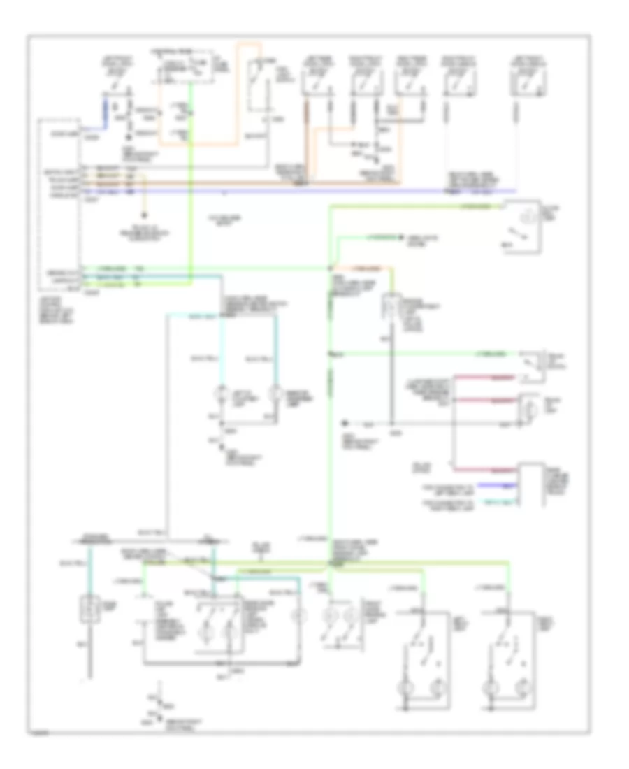
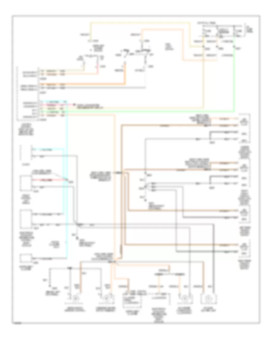
INTERIOR LIGHTS Courtesy Lamps Wiring Diagram for Mercury Grand Marquis GS 1998 List of elements for Courtesy Lamps Wiring Diagram for Mercury Grand Marquis GS 1998: 64 (behind right kick panel) (body harn, near left power heated mirror breakout) s505 (body harn, near right "a" pillar) s259 (luggage compt harn, near right rear speaker breakout) s431 (main harn, near message center switch assembly breakout) s236 (roof harn, near center of right "a" pillar) (roof harn, near front dome/ reading lamp breakout) s900 All others B (+) C2026 C2027 C2029 C262 Circuit breaker 20a Demand out Dome lamp Door ajar Engine compartment lamp (ngv & police option) For connection to left deck lamp For connection to right deck lamp Front dome/ reading lamp Fuse 15a G203 G203 (behind right kick panel) Glove box lamp Handle sw Headlights system Hot at all times I/p fuse panel Lamps out Left front door handle switch Left front door latch switch Left i/p courtesy lamp Left rear door latch switch Left vanity lamp Lighting control module (lcm) (behind left side of dash) Main light switch Nca Police map lamp assembly (center of windshield header) Police option Rear dome/ reading lamp (grand marquis only) Rear flasher (center rear of trunk) Right front door handle switch Right front door latch switch Right i/p right i/p courtesy courtesy lamp lamp Right rear door latch switch Right vanity lamp S206 S208 S216 S227 S262 S290 (main harn, near glove box lamp breakout) S500 S600 S901 S902 Standard production Switch input Trunk ajar Trunk lid lamp Trunk lid release solenoid/ ajar switch Trunk lid switch W/o keyless entry Instrument Illumination Wiring Diagram for Mercury Grand Marquis GS 1998 List of elements for Instrument Illumination Wiring Diagram for Mercury Grand Marquis GS 1998: 69 (behind left kick panel) (behind right kick panel) (body harn, near air supension/evo steering module breakout) (body harn, near left power heated mirror breakout) s507 (body harn, near right front window/ door lock control switch breakout) s289 (digital) (analog) (main harn, near clock breakout) (main harn, near eatc control module breakout) s287 A/c-heater mode switch illumination B (+) C2026 C2027 C2029 C227 C232 C249 C255 C256 c250 C262 Circuit breaker 20a Clock Cluster/ prndl illumination Digital cluster only Dim dn input Dim down Dim up Dim up input Dimming out Door locks system keyless entry circuit Electronic automatic temperature control (eatc) module Front control unit (radio) Fuse 15a G200 G203 Grd Head Headlamp dimmer switch Headlite sw in Hot at all times I/p cigar lighter lamp I/p fuse panel Illumination Instrument cluster Led switch illum Left rear window control switch Lighting control module (lcm) (behind left side of dash) Locks input Main light switch Master window/ door lock control switch Message center switch assembly Off Park Parklite sw in Rear window defrost control Right front window/ door lock control switch Right rear window control switch S204 S207 S208 S227 S233 S262 S285 S288 S500 S503 S600 W/ eatc W/o eatc
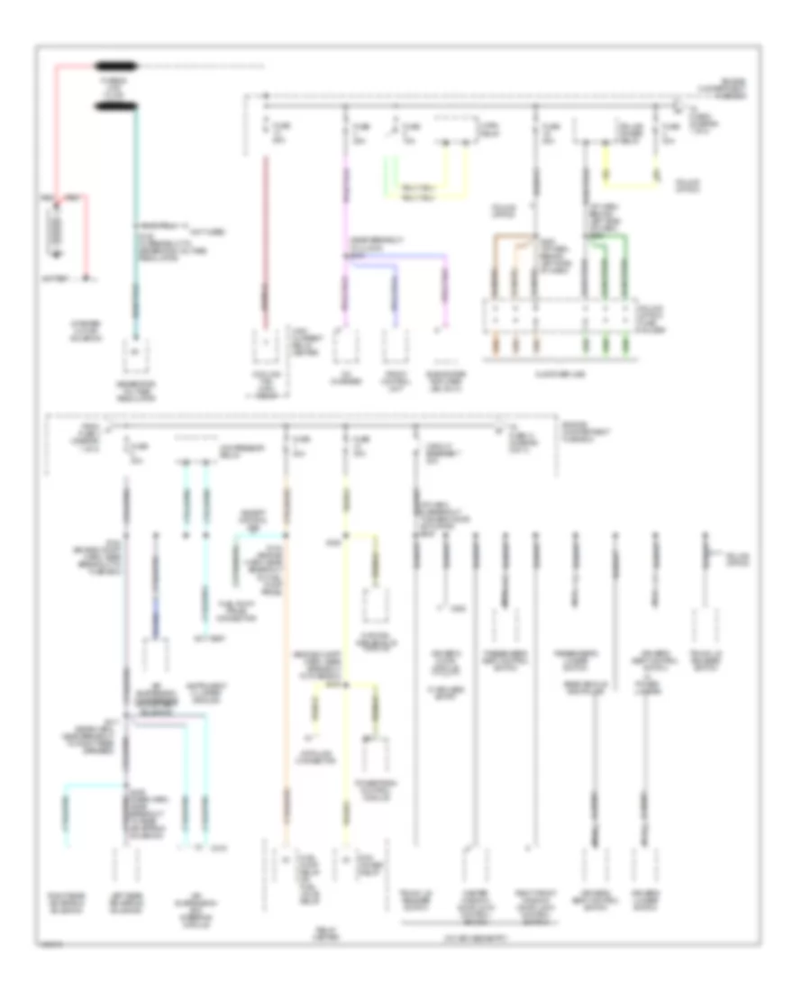
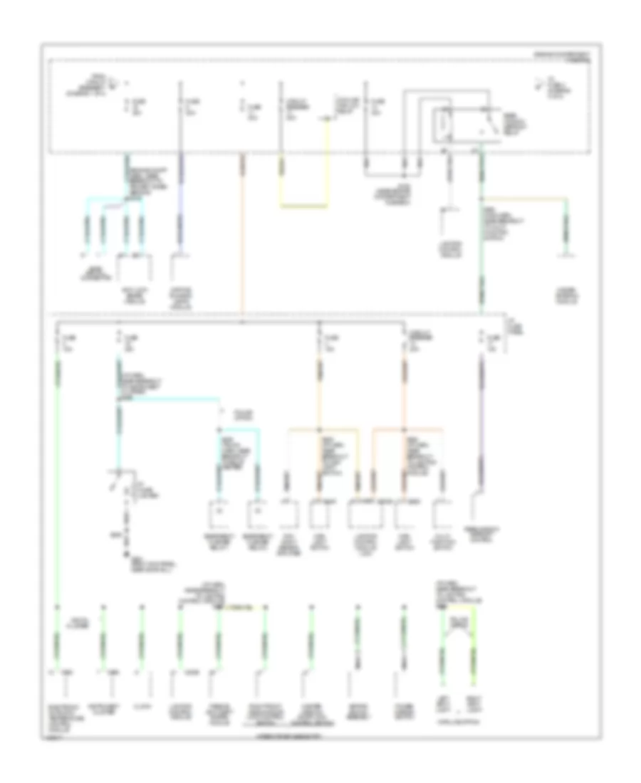
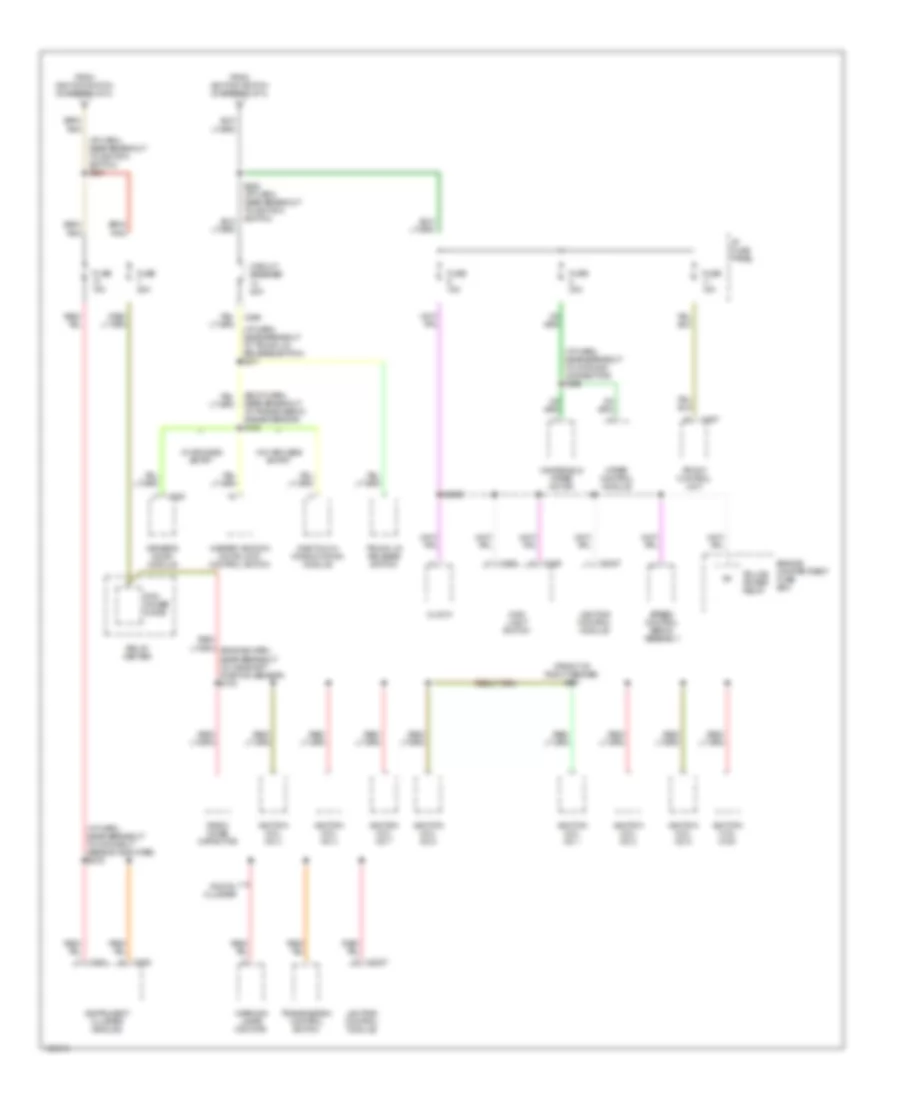
POWER DISTRIBUTION Power Distribution Wiring Diagram (1 of 4) for Mercury Grand Marquis GS 1998 List of elements for Power Distribution Wiring Diagram (1 of 4) for Mercury Grand Marquis GS 1998: 68 (engine compt harn, near breakout to fuse box) s100 (i/p harn, behind left side of dash) s283 (i/p harn, in breakout to blend door actuator) s245 (near breakout to clock) s213 (not used) (rear harn, near breakout to right rear speaker) Air suspension compressor motor/ vent solenoid Air suspension/ evo steering module Base vehicle and police Battery C216 C251 C520 Cd changer Circuit breaker 7 20a Compressor relay Cooling fan high relay Customer use Data link connector Driver's door module Driver's lumbar switch Driver's seat control switch Engine compartment fuse box Except natural gas From a fuse 4 (diagram 1 of 4) Front control unit Fuel pump prime connector Fuel pump relay or fuel valve relay Fuse 15a Fuse 20a Fuse 25a Fuse 30a Fuse 50a Fusible link (12 ga) (gray) Generator/ voltage regulator High current relay center Horn relay Instrument cluster (analog) Left rear air spring solenoid Master window/ door lock control switch Natural gas vehicle module Nca Passenger's lumbar switch Passenger's seat control switch Pcm power relay Police option Police option fuse holder Police power relay Powertrain control module Red Relay center Right front window/ door lock control switch Right rear air spring solenoid S124 (engine harn, near breakout to fuel pump prime) S132 (in breakout to generator voltage regulator) S144 (engine compt harn, near breakout to fuse box) S155 S282 (i/p harn, behind left side of dash) S406 (rear harn, near breakout to rear air spring solenoid) S411 Starter/ motor solenoid Subwoofer amplifier (jbl only) To fuse 14 (diagram 2 of 4) To fuse 8 (diagram 1 of 4) Trunk lid release switch W/ keyless entry W/ power lumbar W/o keyless entry Power Distribution Wiring Diagram (2 of 4) for Mercury Grand Marquis GS 1998 List of elements for Power Distribution Wiring Diagram (2 of 4) for Mercury Grand Marquis GS 1998: 56 (engine compt harn, near breakout to primary crash sensor) s146 (i/p harn, near breakout to instrument cluster) s294 (i/p harn, near breakout to lighting control module) s228 Anti-lock brake module C2029 C228 C249 C255 C262 Circuit breaker 20a Circuit breaker 30a Clock Cooling fan low relay Day/ night sensor amplifier Daytime running lamps module Digital cluster Electronic automatic temperature control module Emergency flasher relay 1 Emergency flasher relay 2 Engine compartment fuse box Evac and fill connector From circuit breaker 7 (diagram 1 of 4) Fuse 10a Fuse 15a Fuse 20a Fuse 30a Fuse 40a G203 (right kick panel, near door sill) Hidden antenna module I/p cigar lighter I/p fuse panel Instrument cluster Keypad switch assembly Left spot light Lighting control module Lighting control module (lcm) Main light switch Master window/ door lock control switch Multi- function switch Nca Passive anti-theft system module Police option Power mirror switch Rear window defrost control Rear window defrost relay Right front window/door lock control switch Right spot light S153 (near engine compartment fuse box) S206 S252 (main harn, near breakout to multi- function switch) S262 (i/p harn, near breakout to lighting control module) S285 (i/p harn, near breakout to main light switch) S426 (trunk harn, near breakout to relay center) To fuse 2 (diagram 3 of 4) W/police option W/remote keyless entry Power Distribution Wiring Diagram (3 of 4) for Mercury Grand Marquis GS 1998 List of elements for Power Distribution Wiring Diagram (3 of 4) for Mercury Grand Marquis GS 1998: 62 (analog) (digital) (i/p harn, near breakout to day/night sensor amplifier) s226 (i/p harn, near breakout to day/night/ sensor amplifier) s269 (i/p harn, near breakout to ignition switch) s263 A/c wot cutout relay A/c-heater mode switch Acc Air bag diagnostic monitor Air bag electronic crash sensor Air suspension/ evo steering module Anti-lock brake module Blend door actuator Blower motor Brake pedal position switch C216 C251 C255 C256 C277 Daytime running lamps module Digital transmission range sensor Electronic automatic temperature control module Electronic day/night mirror Engine compartment fuse box Evac and fill connector Evo steering module From fuse 14 (diagram 2 of 4) Fuse 10a Fuse 15a Fuse 30a Fuse 50a Generator/ voltage regulator I/p fuse panel Ignition switch Instrument cluster Lock Multi- function switch Nca Off Relay center Run S139 S231 (i/p harn, near clock) S265 (near brake pedal position switch) S272 (i/p harn, near breakout to ignition switch) S274 (i/p harn, near breakout to evo steering module) Shift lock actuator Speed chime module Speed control deac switch Start Starting/ charging system Steering wheel rotation sensor To fuse 2, 6, 11 & circuit breaker 14 (diagram 4 of 4) To fuse 7 & 13 (diagram 4 of 4) Traction control switch Trailer battery charging relay W/ air suspension W/ drl W/ eatc W/o air suspension W/o eatc Power Distribution Wiring Diagram (4 of 4) for Mercury Grand Marquis GS 1998 List of elements for Power Distribution Wiring Diagram (4 of 4) for Mercury Grand Marquis GS 1998: 51 (body harn, near breakout to transmission range sensor) s128 (front of right fender) s151 (i/p harn, near breakout to datalink connector) s266 (i/p harn, near breakout to day/night sensor amplifier) s276 (i/p harn, near breakout to ignition switch) s221 (i/p harn, near breakout to trunk lid release switch) s211 C2027 C249 C250 C251 C257 C262 C298 C520 Circuit breaker 20a Clock Digital cluster Driver's door module Engine compartment fuse box From ignition switch (diagram 3 of 4) Front control unit Fuse 15a Fuse 25a Fuse 30a I/p fuse panel Ignition coil no 1 Ignition coil no 2 Ignition coil no 3 Ignition coil no 4 Ignition coil no 5 Ignition coil no 6 Ignition coil no 7 Ignition coil no 8 Instrument cluster (analog) Lighting control module Main light switch Master window/ door lock control switch One touch window down module Pcm power diode Police power relay Radio noise capacitor Relay center S2009 Speed control servo assembly Transmission control switch Trunk lid release switch W/ keyless entry W/o keyless entry Warning lamps monitor Windshield wiper motor Wiper control module
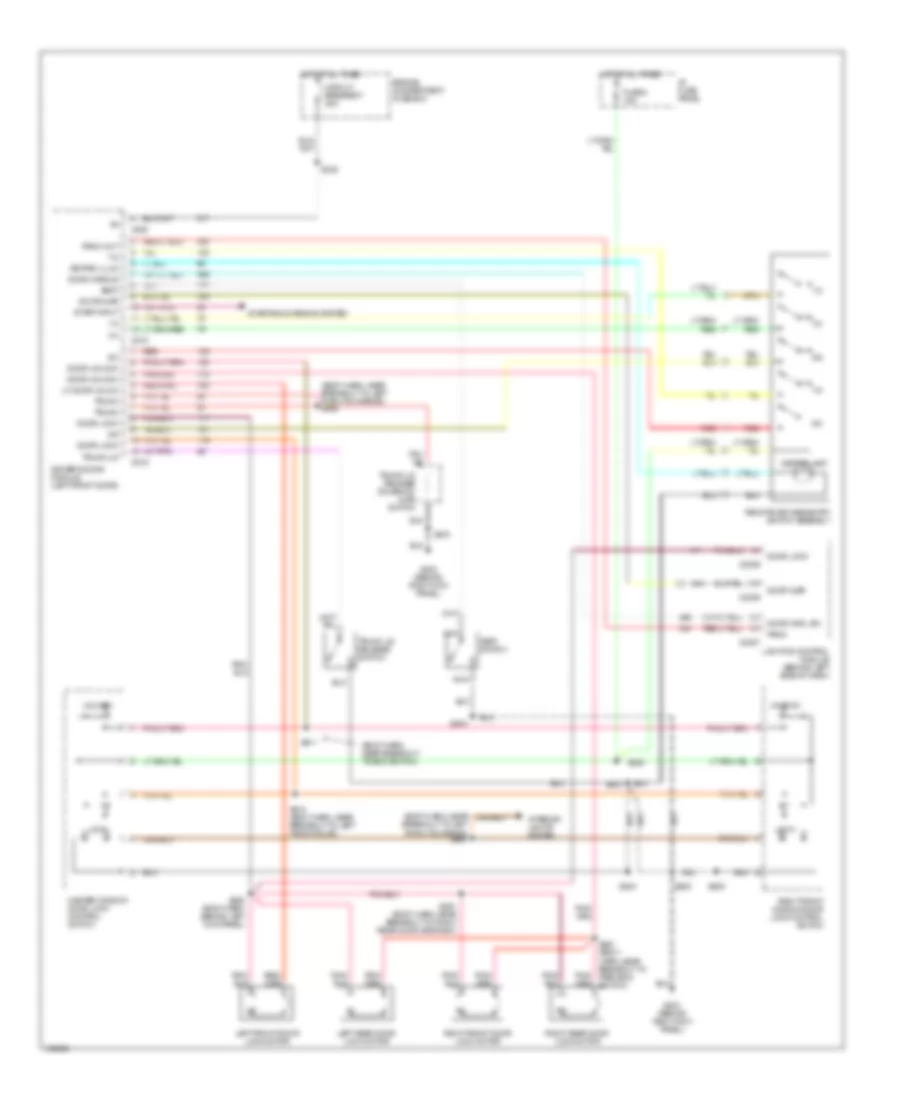
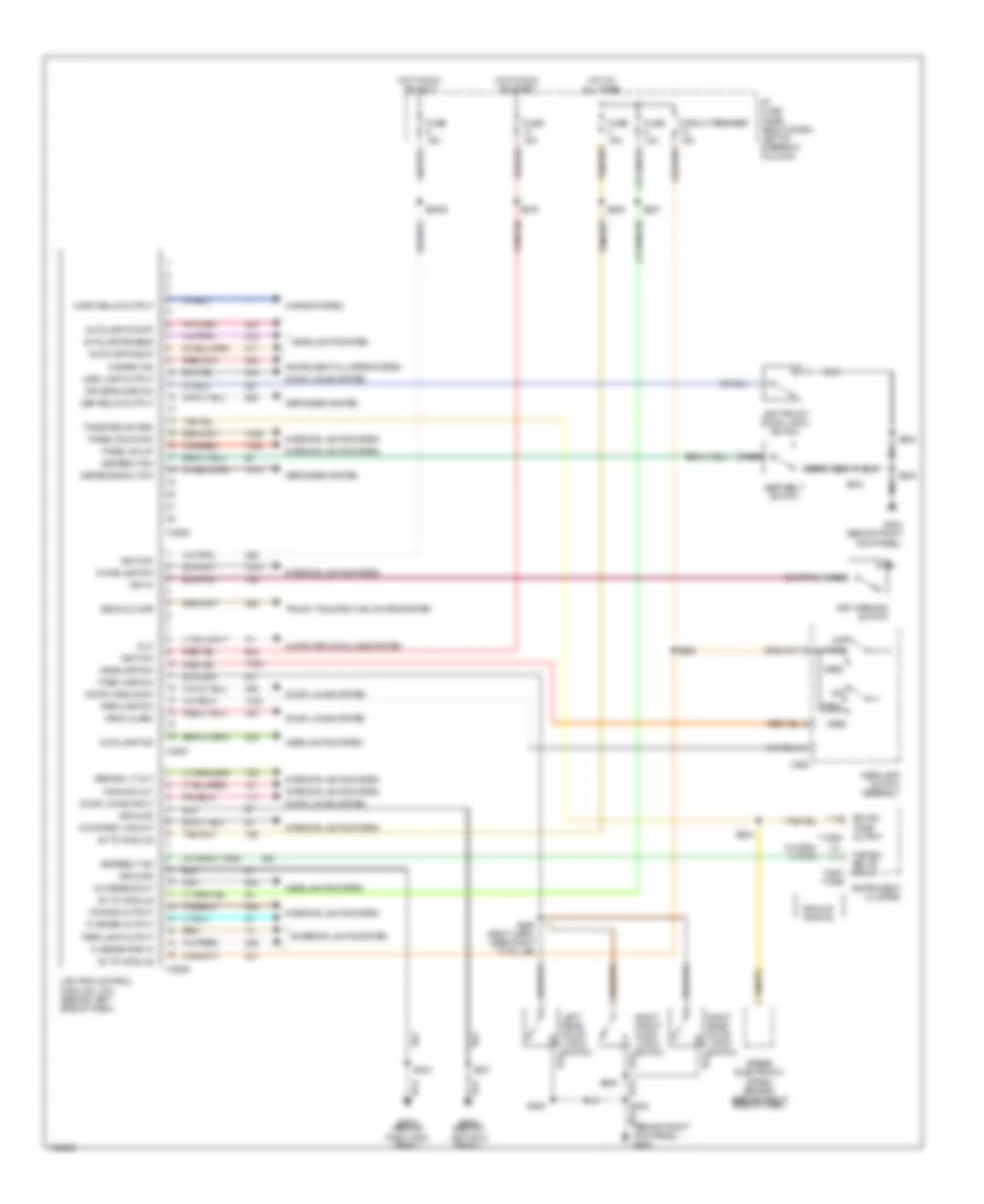
POWER DOOR LOCKS Door Lock Wiring Diagram for Mercury Grand Marquis GS 1998 List of elements for Door Lock Wiring Diagram for Mercury Grand Marquis GS 1998: 24 (body harn, behind left kick panel) s260 (body harn, near breakout to boo switch) s261 (body harn, near breakout to right rear door grommet) s291 C2029 Circuit breaker 7 20a Door lock in Engine compartment fuse box G203 (behind right kick panel) Hot at all times Interior lights system Left front door lock motor Left rear door lock motor Lighting control module (behind left side of dash) Lock Master window/door lock control switch Right front door lock motor Right front window/door lock control switch Right rear door lock motor S208 S245 S503 S507 (body harn, near breakout to power heated mirror) S600 Unlock Keyless Entry Wiring Diagram for Mercury Grand Marquis GS 1998 List of elements for Keyless Entry Wiring Diagram for Mercury Grand Marquis GS 1998: 65 (body harn, near breakout to boo switch) (body harn, near breakout to left pwr htd mirror) s506 1/2 3/4 5/6 7/8 9/0 Breakout to left pwr htd mirror) s507 C2026 C2027 C2029 C518 C519 C520 Circuit breaker 7 20a Door ajar Door handle Door hndl sw Door lock Door unlock Driver's door module (left front door) Engine compartment fuse box Fuse 8 15a G203 (behind right kick panel) Hot at all times I/p fuse panel Interior lights system Keypad illum Keypad lamp Left front door lock motor Left rear door lock motor Lf door unlck Lighting control module (behind left side of dash) Lock Master window/ door lock control switch Nca Panic Panic out Red Remote keyless entry switch assembly Right front door lock motor Right front window/door lock control switch Right rear door lock motor S208 S228 S245 S260 (body harn, behind left kick panel) S261 (body harn, near breakout to park boo switch) S291 (body harn, near breakout to right rear door grommet) S304 S403 S500 S503 S510 (body harn, near breakout to left front door) S511 S600 Seat Seat switch Start input Starting/charging system Trunk Trunk lid Trunk lid release solenoid/ ajar switch Trunk lid release switch Unlock
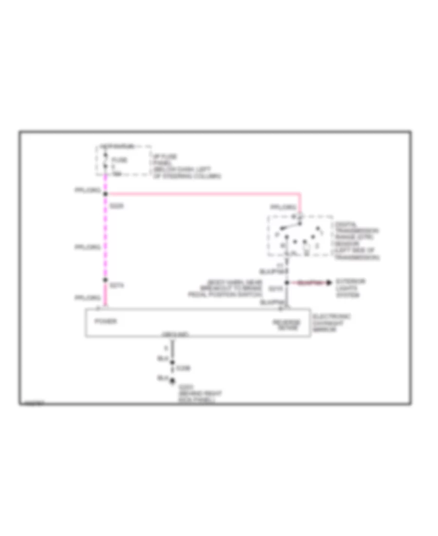
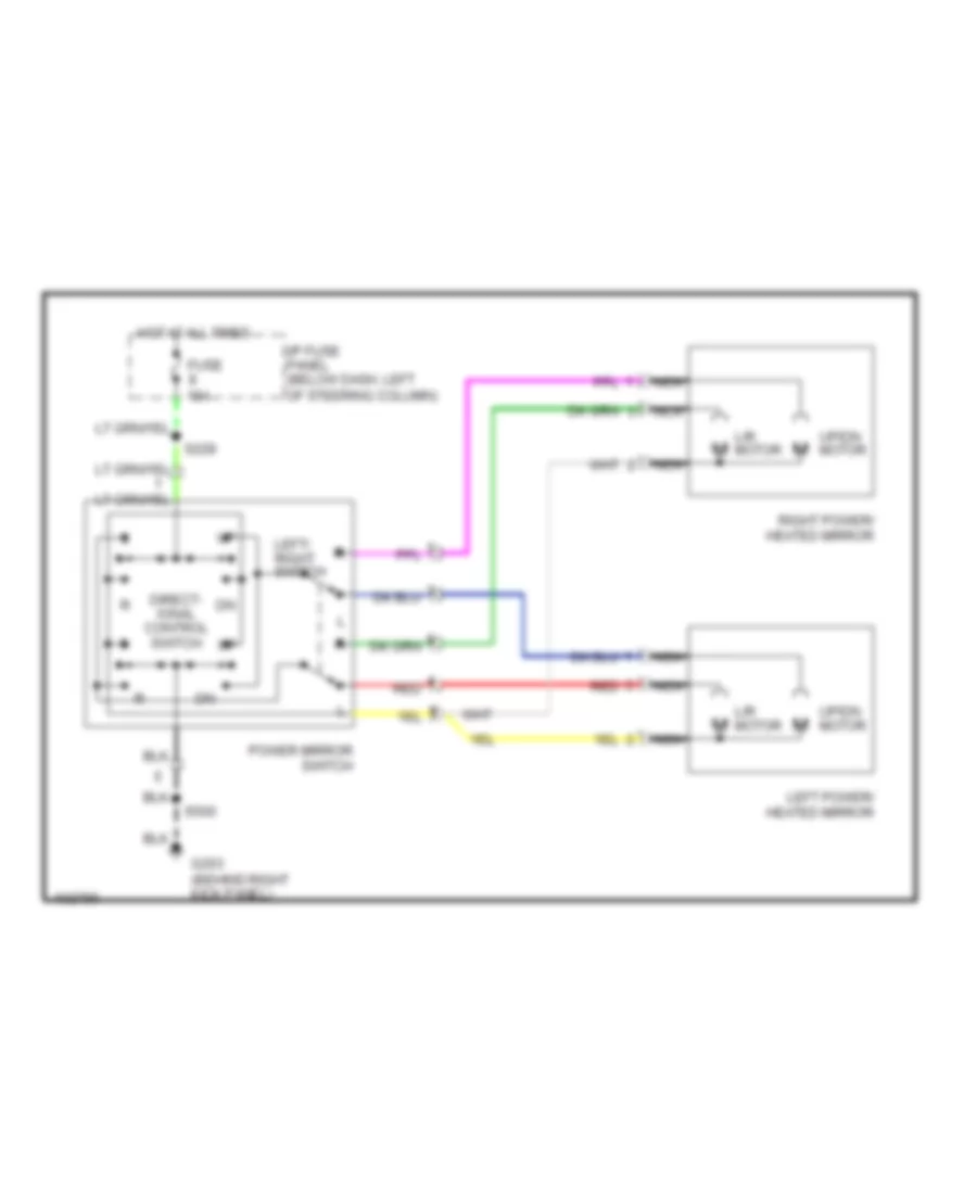
POWER MIRRORS Photochromic Mirror Wiring Diagram for Mercury Grand Marquis GS 1998 List of elements for Photochromic Mirror Wiring Diagram for Mercury Grand Marquis GS 1998: 15 (body harn, near breakout to brake pedal position switch) Digital transmission range (dtr) sensor (left side of transmission) Electronic day/night mirror Exterior lights system Fuse 15a G203 (behind right kick panel) Ground Hot in run I/p fuse panel (below dash, left of steering column) Power Reverse S208 S215 S226 S274 Power Mirror Wiring Diagram for Mercury Grand Marquis GS 1998 List of elements for Power Mirror Wiring Diagram for Mercury Grand Marquis GS 1998: 15 Direct- ional control switch Fuse 15a G203 (behind right kick panel) Hot at all times I/p fuse panel (below dash, left of steering column) L/r motor Left power/ heated mirror Left/ right switch Nca Power mirror switch Red Right power/ heated mirror S228 S500 Up/dn motor
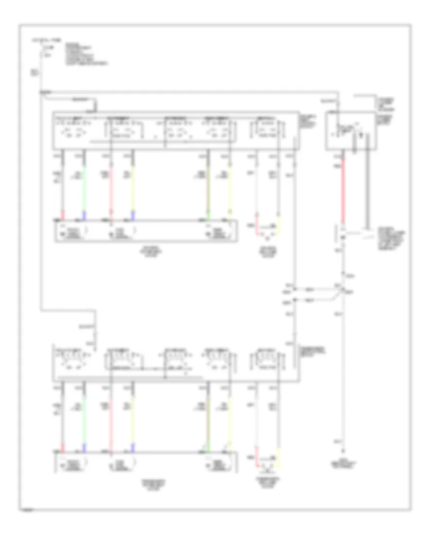
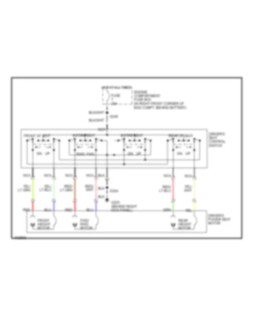
POWER SEATS 6-Way, Recliner & Lumbar Power Seat Wiring Diagram for Mercury Grand Marquis GS 1998 List of elements for 6-Way, Recliner & Lumbar Power Seat Wiring Diagram for Mercury Grand Marquis GS 1998: 33 nca Driver's lumbar air bladder Driver's lumbar switch Driver's power lumbar compressor (under front of left seat assembly) Driver's power seat motor Driver's recliner motor Driver's seat control switch Engine compartment fuse box (in right front corner of eng compt, behind battery) Entire seat Front height motor Front of seat Fuse 20a Fwd Fwd/ rwd motor G203 (behind right kick panel) Hot at all times Inflate Nca Passenger's power seat motor Passenger's recliner motor Passenger's seat control switch Rear height motor Rear of seat Red Red Rwd S208 S245 S304 S500 S600 Seat back Vent Driver Power Seat Wiring Diagram for Mercury Grand Marquis GS 1998 List of elements for Driver Power Seat Wiring Diagram for Mercury Grand Marquis GS 1998: 18 Driver's power seat motor Driver's seat control switch Engine compartment fuse box (in right front corner of eng compt, behind battery) Entire seat Front height motor Front of seat Fuse 20a Fwd Fwd/ rwd motor G203 (behind right kick panel) Hot at all times Nca Rear height motor Rear of seat Red Rwd S245 S304
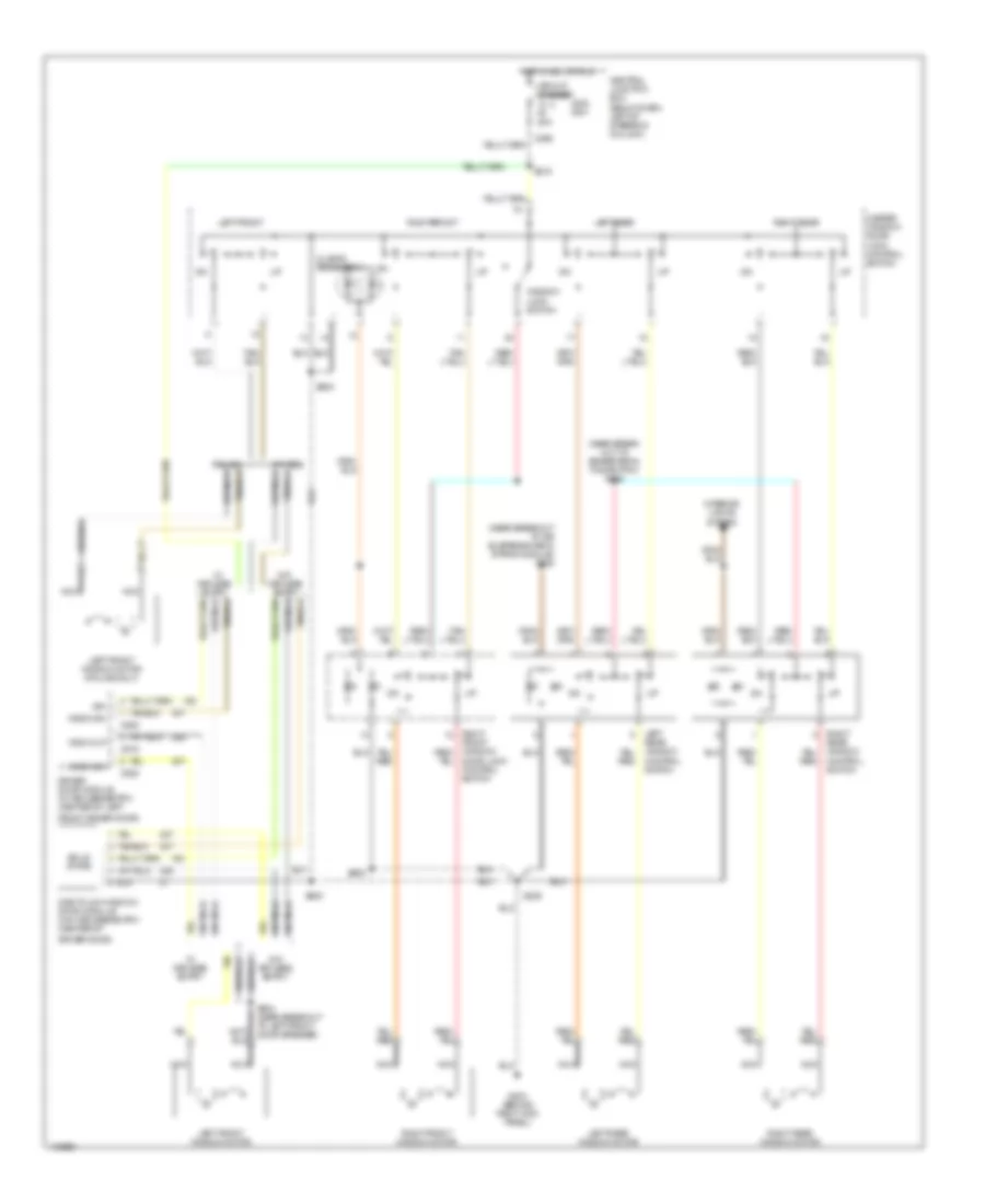
POWER WINDOWS Power Window Wiring Diagram for Mercury Grand Marquis GS 1998 List of elements for Power Window Wiring Diagram for Mercury Grand Marquis GS 1998: 48 (2 led's per switch) (near break- out to brake pedal pos switch) s264 (near breakout to air suspension/evo strng module) s288 C298 C518 C520 Central junction box (below dash, left of steering column) Circuit breaker 20a Door lock control switch Driver door module (w/ keyless entry) (center of left Driver door) Entry Front driver door) G203 (behind right kick panel) Hot in acc or run Ign Interior lights system Keyless Left Left front Left front window motor Left front window motor (police only) Left rear Left rear window motor Master window/ door lock control switch Nca One touch window down module (w/o keyless entry) (center of Others Police Rear window control switch Right Right front Right front window motor Right rear Right rear window motor S208 S218 S500 S503 S504 (near breakout to left front door speaker) S600 Solid state W/ keyless entry W/o W/o keyless entry Window lock switch Wndw dn Wndw up
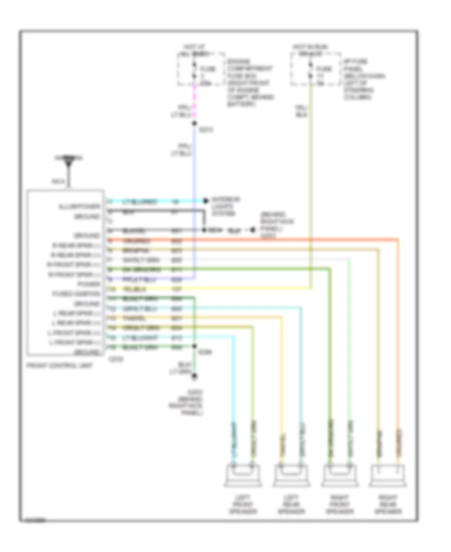
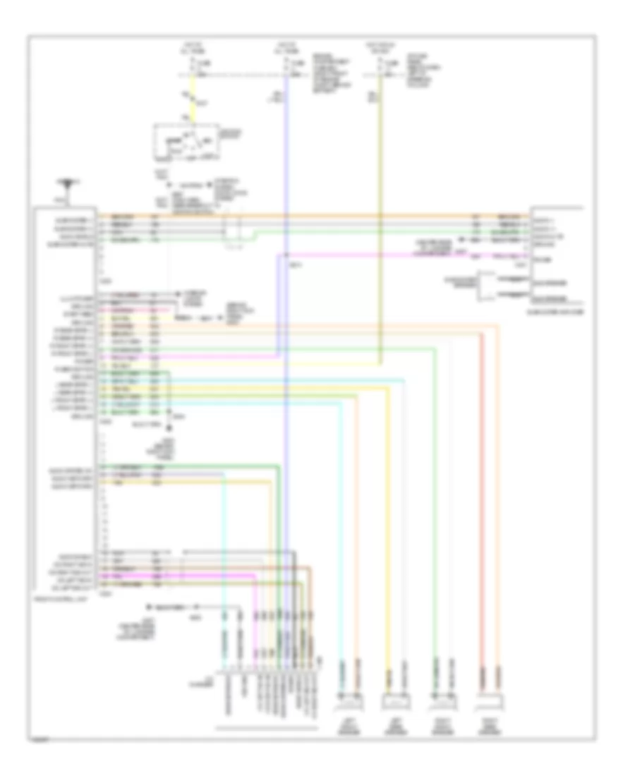
RADIO Base Radio for Mercury Grand Marquis GS 1998 List of elements for Base Radio for Mercury Grand Marquis GS 1998: 32 (behind right kick panel) g203 Antenna C232 Engine compartment fuse box (right front of engine compt, behind battery) Front control unit Fuse 25a Fuse 5a Fused ignition G203 (behind right kick panel) Ground Hot at all times Hot in run or acc I/p fuse panel (below dash, left of steering column) Illum power Interior lights system L front spkr (+) L front spkr (-) L rear spkr (+) L rear spkr (-) Left front speaker Left rear speaker Nca Power R front spkr (+) R front spkr (-) R rear spkr (+) R rear spkr (-) Right front speaker Right rear speaker S204 S213 S284 with CD Changer for Mercury Grand Marquis GS 1998 List of elements for with CD Changer for Mercury Grand Marquis GS 1998: 70 (behind right kick panel) g203 (center rear of luggage compartment) Acc Antenna Audio (+) Audio (-) Audio mute Audio network Audio shield Audio system on C224 C230 C232 C401 C499 Cd changer Cd left sig in Cd left sig out Cd right sig in Cd right sig out Engine compartment fuse box (right front of engine compt, behind battery) Front control unit Fuse 25a Fuse 30a Fuse 5a Fused ignition G203 (behind right kick panel) G407 G407 (center rear of luggage compartment) Ground Hot at all times Hot in run or acc I/p fuse panel (below dash, left of steering column) Ignition switch Illum power Interior lights system L front spkr (+) L front spkr (-) L rear spkr (+) L rear spkr (-) Left front speaker Left rear speaker Lock Nca Off Power R front spkr (+) R front spkr (-) R rear spkr (+) R rear spkr (-) Right front speaker Right rear speaker Run S127 S204 S213 S267 (main harn, near breakout to ignition switch) S284 S408 Sta Start Start feed Starting system, door locks system Sub speaker Subwoofer (+) Subwoofer (-) Subwoofer amplifier Subwoofer mute Subwoofer speaker Tan
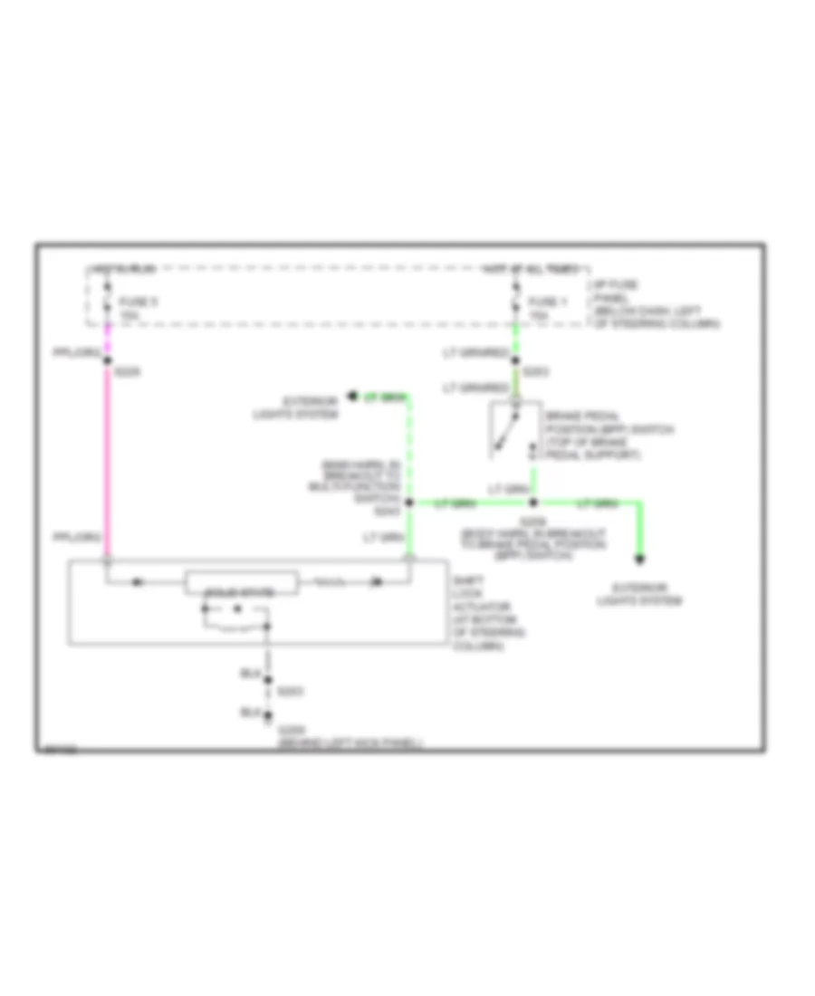
SHIFT INTERLOCKS Shift Interlock Wiring Diagram for Mercury Grand Marquis GS 1998 List of elements for Shift Interlock Wiring Diagram for Mercury Grand Marquis GS 1998: 15 (main harn, in breakout to multi-function switch) s243 Brake pedal position (bpp) switch (top of brake pedal support) Exterior lights system Fuse 1 15a Fuse 5 15a G200 (behind left kick panel) Hot at all times Hot in run I/p fuse panel (below dash, left of steering column) S203 S226 S258 (body harn, in breakout to brake pedal position (bpp) switch) S263 Shift lock actuator (at bottom of steering column) Solid state
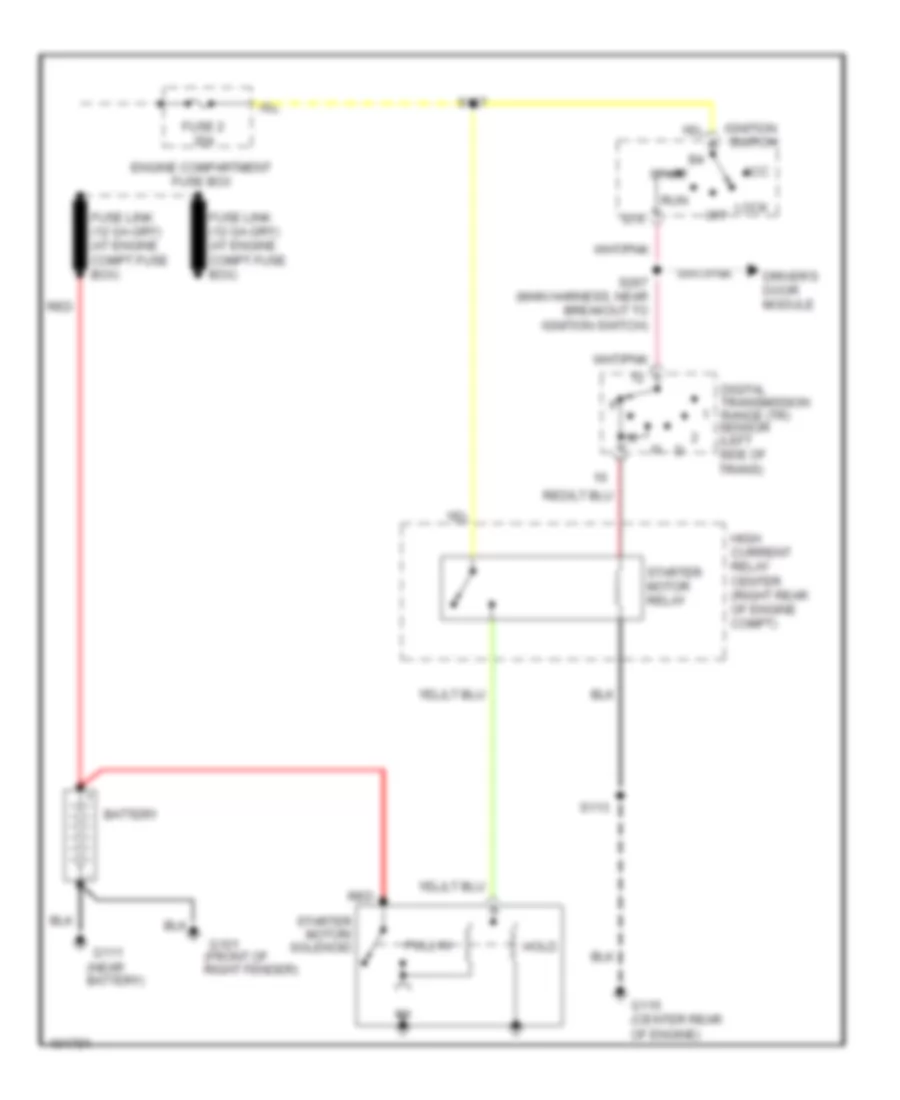
STARTING/CHARGING Charging Wiring Diagram for Mercury Grand Marquis GS 1998 List of elements for Charging Wiring Diagram for Mercury Grand Marquis GS 1998: 22 (not used) Battery C251 C251 c256 C256 Charge indicator Engine compartment fuse box Fuse 10a Fuse 30a G101 (front of right fender) G111 (near battery) Generator/ voltage regulator Hot in run I/p fuse panel Instrument cluster Red S127 S132 S231 Starter motor/ solenoid W/ analog cluster W/ digital cluster Starting Wiring Diagram for Mercury Grand Marquis GS 1998 List of elements for Starting Wiring Diagram for Mercury Grand Marquis GS 1998: 25 (near battery) Acc Battery Digital transmission range (tr) sensor (left side of trans) Driver's door module Engine compartment fuse box Fuse 2 30a G101 (front of right fender) G111 G115 (center rear of engine) High current relay center (right rear of engine compt) Hold Ignition switch Lock Off Pull in Red Run S113 S127 S267 (main harness, near breakout to ignition switch) Sta Start Starter motor relay Starter motor/ solenoid
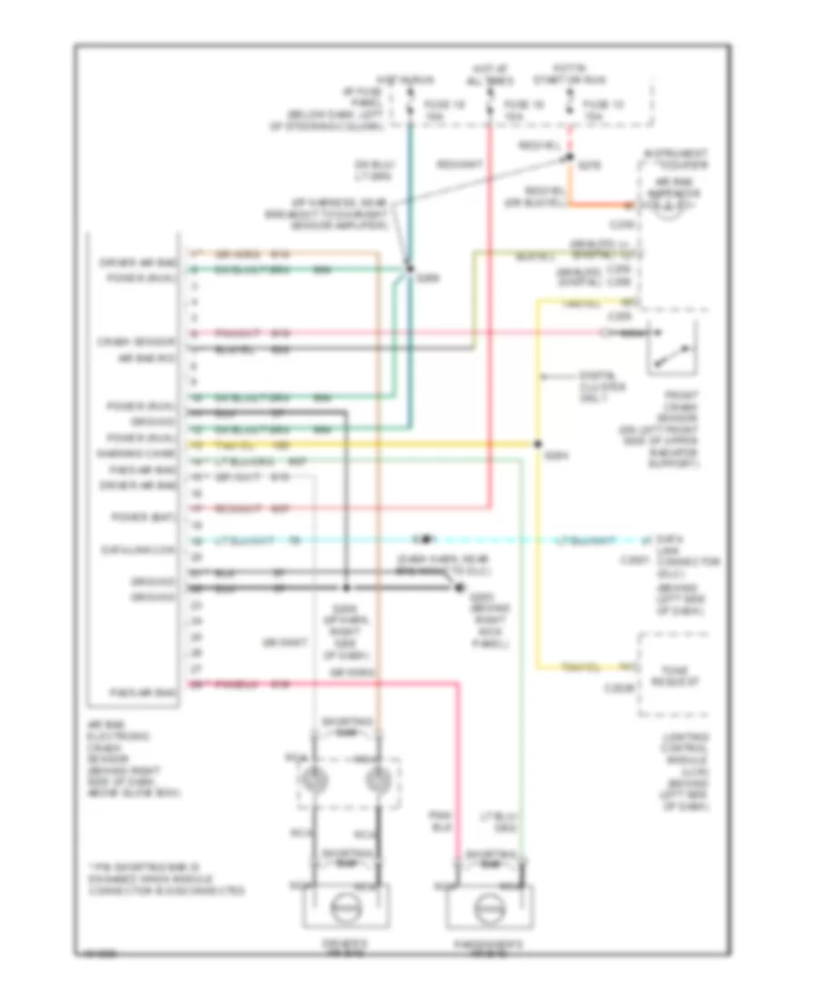
SUPPLEMENTAL RESTRAINTS Supplemental Restraint Wiring Diagram for Mercury Grand Marquis GS 1998 List of elements for Supplemental Restraint Wiring Diagram for Mercury Grand Marquis GS 1998: 44 (analog) (digital) (behind left side of dash) (behind right kick panel) (dash harn, near breakout to dlc) (i/p harn, right side of dash) (i/p harness, near breakout to day/night sensor amplifier) * pin shorting bar is engaged when module connector is disconnected Air bag electronic crash sensor (behind right side of dash, above glove box) Air bag ind Air bag indicator C2026 C250 C255 C256 Crash sensor Data link c2021 connector (dlc) Data link con Digital cluster only Driver air bag Driver's air bag Front crash sensor (on left front side of upper radiator support) Fuse 10 10a Fuse 13 15a Fuse 18 10a G203 Ground Hot at all times Hot in run i/p fuse panel (below dash, left of steering column) Hot in start or run Instrument cluster Lighting control module (lcm) (behind left side of dash) Nca Pass air bag Passenger's air bag Power (bat) Power (run) S209 S269 S271 S276 S284 Shorting bar Tone request Warning chime
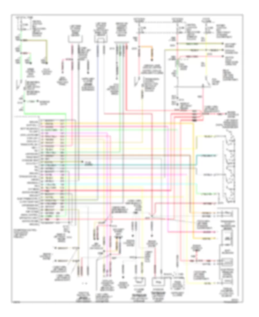
TRANSMISSION Transmission Wiring Diagram for Mercury Grand Marquis GS 1998 List of elements for Transmission Wiring Diagram for Mercury Grand Marquis GS 1998: 114 (12a581 harn, left rear of engine compt) (12a581 harn, left rear of engine compt) s129 (12a581 harn, near breakout to fuel pump prime) (12b636 harn, near breakout to generator) (12b637 harn, near fuel inj 8) (14401 harn, near breakout to data link connector) (7c078 harn, left rear of engine compartment) (behind air cleaner assembly) mass air- flow (maf) sensor (left rear of trans) vehicle speed sensor (left side of trans- mission) output shaft speed (oss) sensor (left side of transmission) digital transmission range sensor (rear of left front fender apron) (rear of left front fender g104 apron) 4r70w transmission A/c cutout Abs module, Analog Anti-theft system, Anti-theft systems Battery junction box (right front of engine compartment) Bpp switch input Brake pedal position (bpp) switch (top of brake pedal support) C250 C255 Central junction box (below dash, left of steering column) Cht sens Control module, instrument cluster Cylinder head Data link + Data link - Data link connector (partial) (behind left side of dash) Data link power Datalink connector Digital Eatc module Elect press cntrl Electronic pressure control solenoid Engine controls system Exterior lights Fuse 15a Fuse 25a Fuse 30a G104 G104 (rear of left front fender apron) G203 (behind Ground Hot at all times Hot in run or start Ignition coils, radio noise capacitor Ignition power Instrument cluster Instrument cluster, cruise control, electronic suspension Intake air Intake air temp Kapwr Maf return Maf sensor sig Multi- function switch Ngv module Output shaft sig Pcm power diode Pcm power relay Powertrain control module (pcm) (left side of firewall) R p Red Red red Ref votage Relay center (left side of engine compartment) Right kick panel) S100 S105 S115 S119 S123 S125 S126 S132 S134 S135 S147 S148 S223 S263 S265 S276 S296 S297 Shift sol 1 Shift solenoid 2 Shift solenoids Signal control Speed control deac switch Ss1 Ss2 Tci lamp Temperature (cht) sensor (top left front of engine) Temperature (iat) sensor (left front of engine) compt) Throttle position (tp) sensor (left side of throtle body) To a/c system Torque conv sol Torque converter clutch (tcc) solenoid Tps signal Tr1 Tr2 Tr3 Tr4 Trans cntrl sw Trans control indicator lamp Trans temp Transmission control switch (tcs) (bottom of steering column) Transmission fluid temperature sensor Vss (-) Vss signal Warning lamps module, lighting
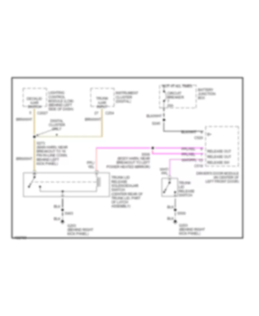
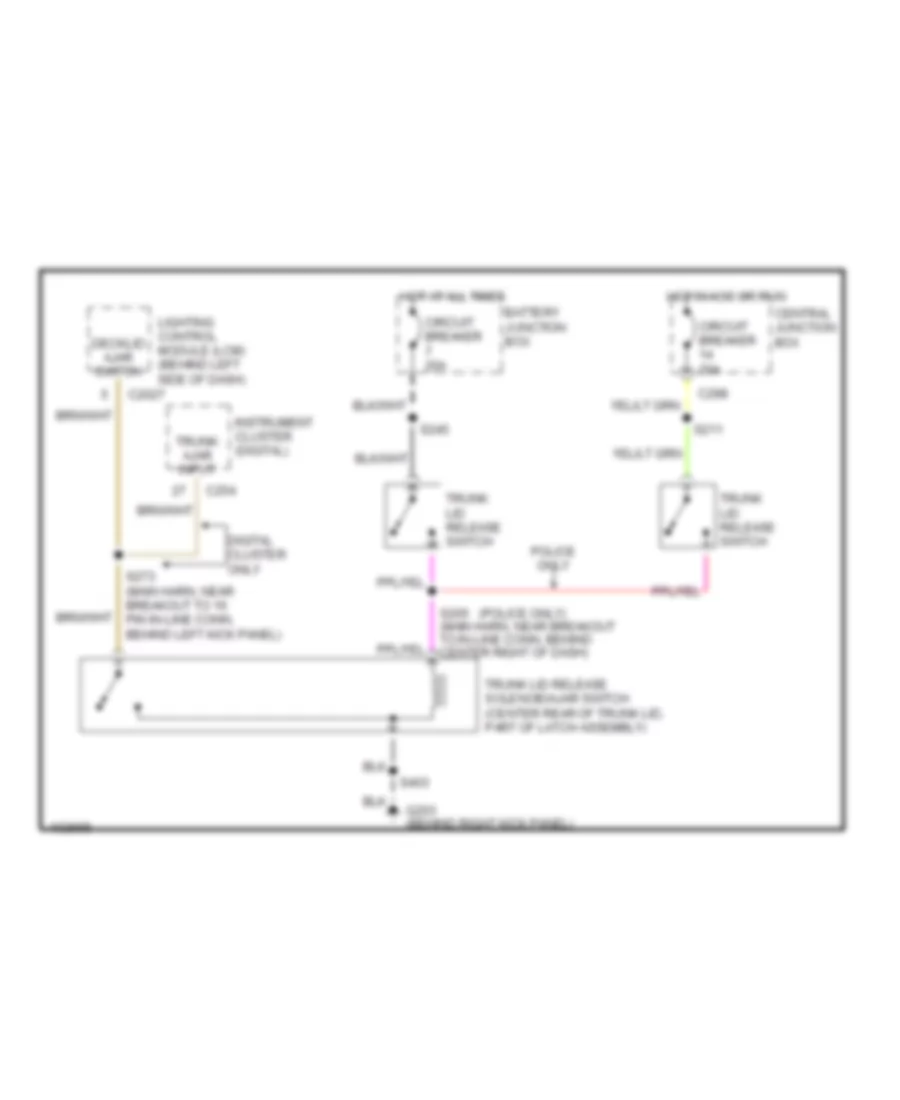
TRUNK, TAILGATE, FUEL DOOR Trunk Release Wiring Diagram, with Keyless Entry for Mercury Grand Marquis GS 1998 List of elements for Trunk Release Wiring Diagram, with Keyless Entry for Mercury Grand Marquis GS 1998: 23 Battery junction box C2027 C254 C519 C520 Circuit breaker 20a Decklid ajar switch Digital cluster only Driver's door module (in center of left front door) G203 (behind right kick panel) Hot at all times Instrument cluster (digital) Lighting control module (lcm) (behind left side of dash) Release out Release sw S245 S273 (main harn, near breakout to 16 pin in-line conn, behind left kick panel) S403 S500 S506 (body harn, near breakout to left power heated mirror) Trunk ajar input Trunk lid release solenoid/ajar switch (center rear of trunk lid, part of latch assembly) Trunk lid release switch Trunk Release Wiring Diagram, without Keyless Entry for Mercury Grand Marquis GS 1998 List of elements for Trunk Release Wiring Diagram, without Keyless Entry for Mercury Grand Marquis GS 1998: 23 (police only) Battery junction box C2027 C254 C298 Central junction box Circuit breaker 20a Decklid ajar switch Digital cluster only G203 (behind right kick panel) Hot at all times Hot in acc or run Instrument cluster (digital) Lighting control module (lcm) (behind left side of dash) Police only S205 (main harn, near breakout to in-line conn, behind center right of dash) S211 S245 S273 (main harn, near breakout to 16 pin in-line conn, behind left kick panel) S403 Trunk ajar input Trunk lid release solenoid/ajar switch (center rear of trunk lid, part of latch assembly) Trunk lid release switch
WARNING SYSTEMS Warning System Wiring Diagrams for Mercury Grand Marquis GS 1998 List of elements for Warning System Wiring Diagrams for Mercury Grand Marquis GS 1998: 91 (behind right kick panel) g203 **19 **c255 *10 **11 *analog **digital Airbag electronic crash sensor (behind right side of dash) Ajar lamp output Autolamp delay Autolamp enable Autolamp ind Autolamp on/off B+ to module C2026 C2027 C2029 C262 Circuit breaker 18a Computer data lines system Courtesy lps out Decklid ajar Def relay output Defogger system Demand lt out Dimming out Dimming output Dlc Dome lamp sw Door handle sw Door locks input Door locks system Driver's ajar sw Exterior lights system Fasten belts input *c251 **c256 Flasher output Flasher pwr in Fuse 15a G200 (behind left kick panel) G203 (behind right kick panel) Ground Hazard ind Head Headlamp sw Headlamp switch assembly Headlights system Heated backlt sw Horn relay output Horns system Hot at all times Hot in run or accy Hot in run or start I/p fuse panel (below dash, left of steering column) Ignition Instrument cluster Instrument cluster system Interior lights system Key in Key warning switch Left front door latch switch Left rear door latch switch Lighting control module (lcm) (behind left side of dash) Low beams out Nca Off Panel dim down Panel dim up Panic alarm Park Parklamp output Parklamp sw Pass. ajar sw Right front door latch switch Right rear door latch switch S2009 S204 S207 S208 S227 S259 (body harn, near right "a" pillar) S262 S276 S284 S285 S304 S500 S600 Seat belt switch Seatbelt ind Seatbelt sw Sound tone output Tone req or grd Trunk, tailgate, fuel doors system
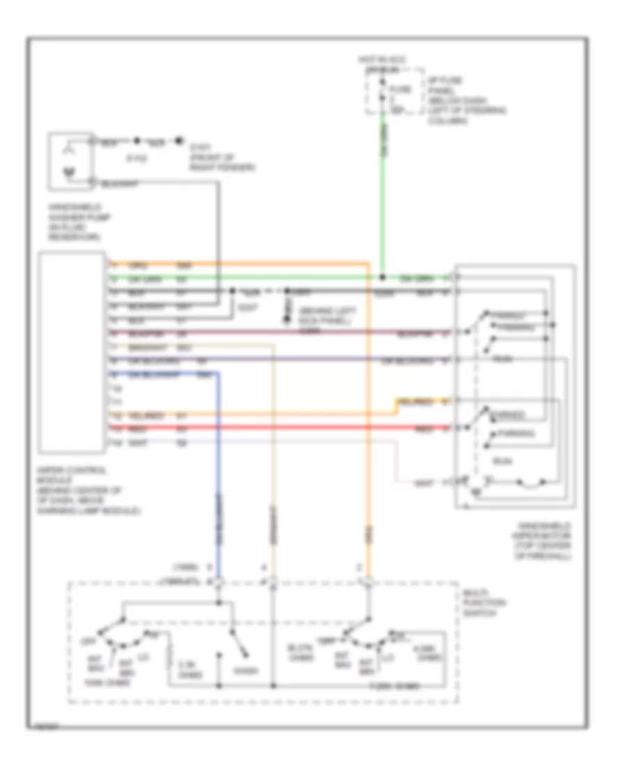
WIPER/WASHER Wiper/Washer Wiring Diagram for Mercury Grand Marquis GS 1998 List of elements for Wiper/Washer Wiring Diagram for Mercury Grand Marquis GS 1998: 28 (1996-97) (1998) (behind left kick panel) g200 100k ohms 3.3k ohms 4.08k 7.25k Fuse 30a G101 (front of right fender) Hot in acc or run I/p fuse panel (below dash, left of steering column) Int max Int min Multi- function switch Off Off 36.27k ohms Ohms Parked Parking Red Run S112 S207 S266 Wash Windshield washer pump (in fluid reservoir) Windshield wiper motor (top center of firewall) Wiper control module (behind center of of dash, above warning lamp module)