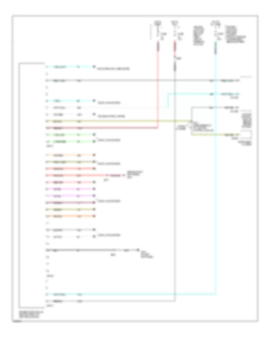
AIR CONDITIONING
Automatic A/C Wiring Diagram (1 of 2) for Mercury Grand Marquis GS 2005

List of elements for Automatic A/C Wiring Diagram (1 of 2) for Mercury Grand Marquis GS 2005:
- (at front of right fender) g109
- (near breakout to passenger air bag deactivation indicator) s210
- A/c demand sig
- Air temp door resistor sig
- Amb temp sens input
- Ambient air temperature sensor (on front of upper radiator support)
- Analog
- Battery
- Battery junction box (bjb) (in right front of engine compartment, behind battery)
- Battery junction box (bjb) (in right front of engine compt, behind battery)
- Blend door +/-
- Blower motor high
- Blower motor relay
- C220a
- C2220b
- C228a
- C228b
- Central junction box (cjb) (below dash, left of steering column)
- Computer data lines system
- Digital
- Ect ind
- Electronic automatic temperature control (eatc) module (behind center of dash)
- Electronic cluster
- Eng/met
- Engine coolant temperature (ect) sensor (on top right front of engine, near fuel injector 1)
- Front blower motor (at right rear of engine compt)
- Front blower motor speed controller (at rear of engine compt)
- Fuse 10a
- Fuse 15a
- Fuse 40a
- G108 (at front of right fender)
- G201 (behind right kick panel)
- G203 (behind right kick panel)
- Ground
- High blower
- Hot at all times
- Hot in run
- Hot in run or start
- In car temp sens
- In-vehicle temperature sensor (behind center of dash)
- Instrument cluster (analog)
- Instrument cluster (digital)
- Instrument illum
- Interior lights system
- Micro- processor
- Red
- Remote ctrl unit
- S203 (in main body wiring harness, near breakout to instrument cluster)
- S207 (in main wiring harness, near breakout to rear window defrost switch)
- Scp bus (+)
- Scp bus (-)
- Sig rtn
- Speed ctrl
- Sunload sens input
- Temp door sig +
- Vbc input
- Vbc output
- Vpwr
Automatic A/C Wiring Diagram (2 of 2) for Mercury Grand Marquis GS 2005
List of elements for Automatic A/C Wiring Diagram (2 of 2) for Mercury Grand Marquis GS 2005:
- (at base of steering column) air bag sliding contact
- (in engine control sensor & fuel charge wiring harness, near breakout to pcm)
- (in main wiring harness, near breakout to passenger air bag deactivation indicator)
- (not
- A/c clutch field coil (at right front of engine)
- A/c clutch relay
- A/c compressor clutch diode
- A/c evaporator discharge air temperature sensor (on right side rear of engine compt)
- A/c pressure transducer sensor (on right side center of engine)
- Audio/climate control switch
- Autolamp/sunload sensor (on upper left side of dash)
- Battery junction box (bjb) (in right front of engine compartment, behind battery)
- C1048a
- C1048b
- C175b
- C175e
- C175t
- C2145b
- C218a
- C218b
- C2208
- C290a
- Engine cooling fan module (left front of engine compt)
- Engine cooling fan motor
- Fan down
- Fan up
- Fuse 15a
- Fuse 50a
- G102 (at front of left fender)
- G109 (at front of right fender)
- G110 (right side of engine)
- G201 (behind right kick panel)
- G203 (behind right kick panel)
- Ground
- Hot at all times
- Hot in start or run
- Lighting control module (behind center of dash)
- Low charge protection switch (at right side of engine compt)
- Phone
- Powertrain control module (pcm) (left rear of engine compt)
- Radio
- Red
- Rest
- S111 (in dash panel to headlamp junction harness, left rear of engine compt)
- S121
- S123
- S126 (in engine control sensor & fuel charge wiring harness, near breakout to cop 4)
- S130 (in dash panel to headlamp junction harness, left rear of engine compt)
- S157 (in engine control sensor & fuel charge wiring harness, near breakout to c192)
- S201 (in main wiring harness, in breakout to adjustable pedal switch)
- S210
- S294 (in steering column control switch jumper harness)
- Temp down
- Temp up
- Temperature blend door actuator (behind right side of dash, on top of a/c plenum)
- Used)
- Vbatt
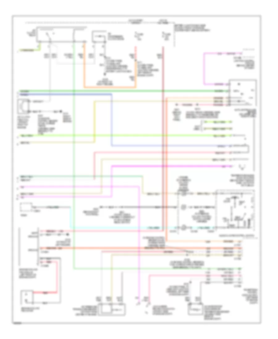
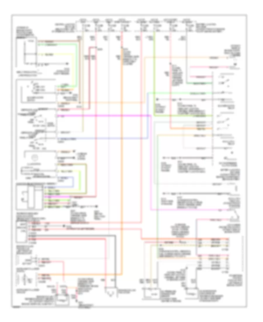
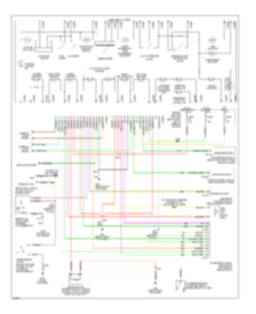
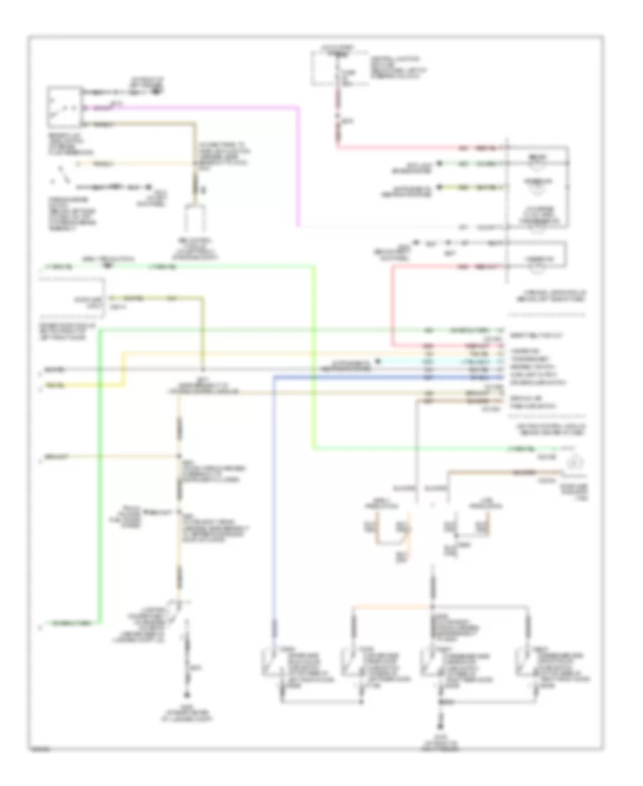
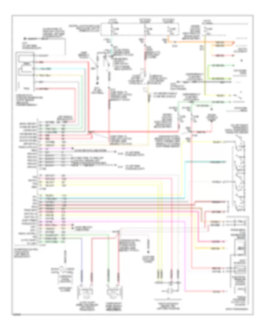
Manual A/C Wiring Diagram for Mercury Grand Marquis GS 2005
List of elements for Manual A/C Wiring Diagram for Mercury Grand Marquis GS 2005:
- (at rear of engine compt) front blower motor resistor assembly
- (at right rear of engine compt) front blower motor
- (in dash panel to
- (in engine control sensor & fuel charge wiring harness, near breakout to pcm)
- (in main wiring harness, near breakout to passenger air bag deactivation indicator) s210
- (left rear of engine compt)
- (not used)
- A/c clutch field coil (at right front of engine)
- A/c clutch relay
- A/c compressor clutch diode
- A/c evaporator discharge air temperature sensor (on right side rear of engine compt)
- A/c pressure transducer sensor (on right side center of engine)
- A/c sw max
- Analog
- Battery junction box (bjb) (in right front of engine compartment, behind battery)
- Battery junction box (bjb) (in right front of engine compt, behind battery)
- Blower motor relay
- Blower motor switch
- C1048a
- C1048b
- C175b
- C175e
- C220a
- C2220b
- C294a
- C294b
- C294c
- C294d
- Central junction box (cjb) (below dash, left of steering column)
- Cold
- Ctrl
- Defrost
- Defrost defrost/floor
- Defrost/floor
- Digital
- Early production
- Ect ind
- Engine coolant temperature (ect) sensor (on top right front of engine, near fuel injector 1)
- Engine cooling fan module (left front of engine compt)
- Engine cooling fan motor
- Floor
- Function selector switch assembly
- Fuse 10a
- Fuse 15a
- Fuse 40a
- Fuse 50a
- G102 (at front of left fender)
- G108 (at front of right fender)
- G109 (at front of right fender)
- G110 (right side of engine)
- G201 (behind right kick panel)
- G203 (behind right kick panel)
- G204 (behind right kick panel)
- Ground
- Headlamp junction harness, near breakout to battery junction box)
- High
- Hot at all times
- Hot in run
- Hot in start or run
- Illumination
- Instrument cluster (analog)
- Instrument cluster (digital)
- Interior lights system
- Late production
- Low
- Low charge protection switch (at right side of engine compt)
- Med high
- Med low
- Mode switch
- Off
- Off off panel
- Panel
- Panel/floor
- Powertrain control module (pcm)
- Red
- S111 (in dash panel to headlamp junction harness, left rear of engine compt)
- S121
- S121 (in dash panel to headlamp junction harness, near breakout to battery junction box)
- S122
- S123
- S126 (in engine control sensor & fuel charge wiring harness, near breakout to cop 4)
- S130 (in dash panel to headlamp junction harness, left rear of engine compt)
- S157 (in engine control sensor & fuel charge wiring harness, near breakout to c192)
- S207 (in main wiring harness, near breakout to rear window defrost switch)
- S209
- S276 (in main wiring harness, near breakout to instrument cluster)
- Temp ctrl potentiometer
- Temperature blend door actuator (behind right side of dash, on top of a/c plenum)
- Vbatt
- Vpwr
- Warm
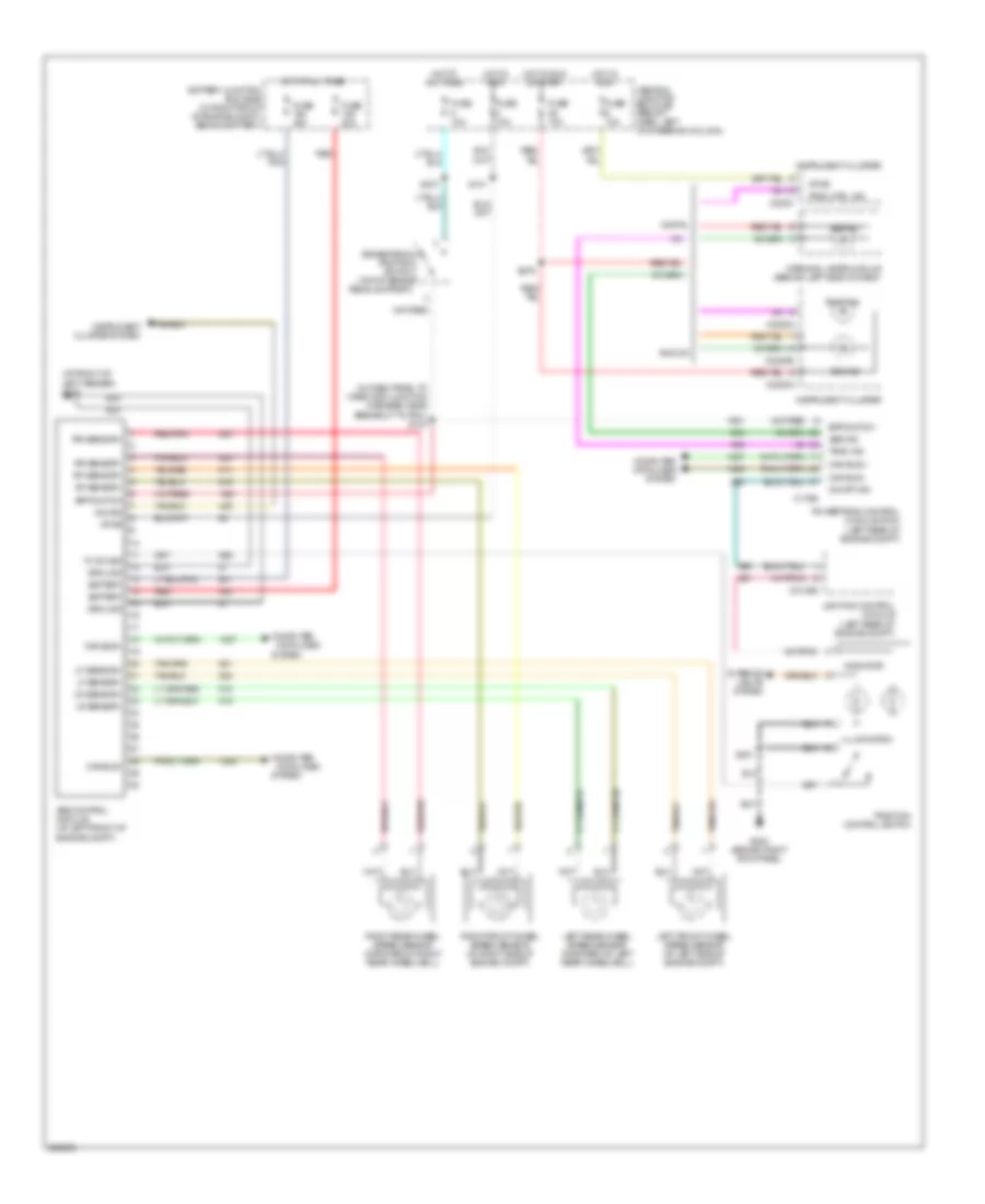
ANTI-LOCK BRAKES
Anti-lock Brakes Wiring Diagram for Mercury Grand Marquis GS 2005
List of elements for Anti-lock Brakes Wiring Diagram for Mercury Grand Marquis GS 2005:
- (at front of left fender) g103
- (in dash panel to headlamp junction harness, near breakout to pcm) s103
- Abs control module (at left front of engine compt)
- Abs ind
- Analog
- Battery
- Battery junction box (bjb) (in right front of engine compt, behind battery)
- Bpp switch
- Brake pedal position switch (top of brake pedal support)
- C175b
- C2145b
- C220c
- C2220a
- C2220b
- Can bus +
- Can bus -
- Can bus+
- Can bus-
- Central junction box (cjb) (below dash, left of steering column)
- Computer
- Computer data lines system
- Data lines
- Digital
- Fuse 10a
- Fuse 20a
- Fuse 40a
- G203 (behind right kick panel)
- Ground
- Hot at all times
- Hot in run
- Hot in run or start
- Illumination
- Ind sig
- Indicator
- Instrument cluster
- Instrument cluster system
- Interior lights system
- Left front wheel speed sensor (at left side of engine compt)
- Left rear wheel speed sensor (forward of left rear wheelwell)
- Lf sensor+
- Lf sensor-
- Lighting control module (left rear of engine compt)
- Lr sensor+
- Lr sensor-
- On/off ind
- Powertrain control module (pcm) (left rear of engine compt)
- Red
- Red/pnk
- Rf sensor+
- Rf sensor-
- Right front wheel speed sensor (at right side of engine compt)
- Right rear wheel speed sensor (forward of right rear wheelwell)
- Rr sensor+
- Rr sensor-
- S101
- S201
- S237
- S276
- System
- Tc sw sig
- Trac ctrl ind
- Trac ind
- Traction control switch
- Vpwr
- Warning lamps module (behind left side of dash)
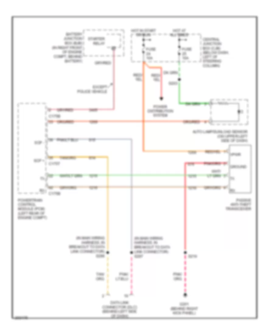
ANTI-THEFT
Anti-theft Wiring Diagram for Mercury Grand Marquis GS 2005
List of elements for Anti-theft Wiring Diagram for Mercury Grand Marquis GS 2005:
- (in main wiring harness, in breakout to data link connector) s296
- (in main wiring harness, in breakout to data link connector) s297
- Auto lamp/sunload sensor (on upper left side of dash)
- Battery junction box (bjb) (in right front of engine compt, behind battery)
- C175b
- C175t
- Central junction box (cjb) (below dash, left of steering column)
- Data link connector (dlc) (behind left side of dash)
- Except police vehicle
- Fuse 10a
- G201 (behind right kick panel)
- Ground
- Hot at all times
- Hot in start or run
- Passive anti-theft transceiver
- Power distribution system
- Powertrain control module (pcm) (left rear of engine compt)
- S203
- S210
- Scp +
- Scp -
- Starter relay
- Vpwr
BODY CONTROL MODULES
Body Control Modules Wiring Diagram for Mercury Grand Marquis GS 2005
List of elements for Body Control Modules Wiring Diagram for Mercury Grand Marquis GS 2005:
- (behind right kick panel) g201
- Battery junction box (bjb) (in right front of engine compartment, behind battery)
- C2145a
- C2145b
- C220b
- C501a
- C501b
- C501c
- Central junction box (cjb) (below dash, left of steering column)
- Computer data lines system
- Cruise control system
- Digital cluster
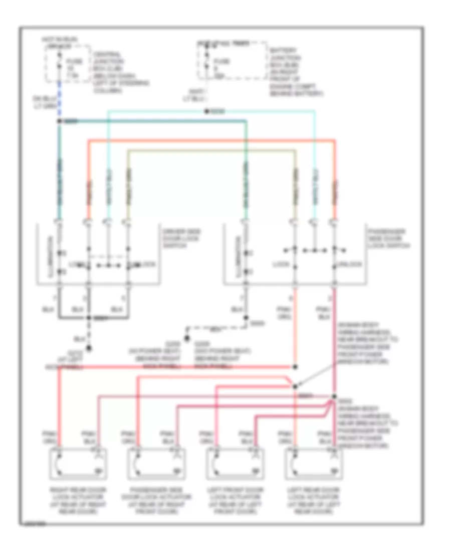
- Door locks system
- Driver door module (bottom front of left front door)
- Fuse 10a
- Fuse 20a
- Fuse 5a
- G212 (at left kick panel)
- Hot at all times
- Hot in run
- Hot in start
- Instrument cluster
- Lighting control module (behind center of dash)
- S217
- S262
- S277 (near breakout to lighting control module)
- S500
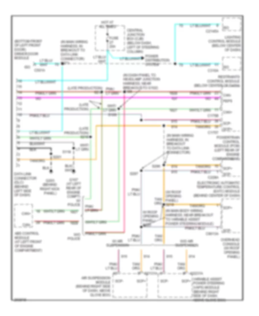
COMPUTER DATA LINES
Computer Data Lines Wiring Diagram for Mercury Grand Marquis GS 2005
List of elements for Computer Data Lines Wiring Diagram for Mercury Grand Marquis GS 2005:
- (bottom front of left front door) driver door module
- (in dash panel to headlamp junction harness, near breakout to g102)
- (in main body wiring harness, near breakout to variable assist power steering module)
- (in main wiring harness, in breakout to data link connector)
- (in main wiring harness, in breakout to data link connector) s271
- (late production)
- (late production) s218
- (w/ roof opening panel) s219
- Abs control module (at left front of engine compartment)
- Air suspension module (behind right side of dash, above glove box)
- C175b
- C175t
- C2131a
- C2145a
- C2231a
- C228a
- C310a
- C501a
- C9013a
- Can+
- Can-
- Central junction box (cjb) (below dash, left of steering column)
- Data link connector (dlc) (behind left side of dash)
- Electronic automatic temperature control (eatc) module (behind center of dash)
- Fuse 20a
- G107 (at left rear of engine compt)
- G203 (behind right kick panel)
- Hot at all times
- Iso
- Lighting control module (below center of dash)
- Overhead console (w/ roof opening panel)
- Peps
- Power distribution system
- Powertrain control module (pcm) (left rear of engine compartment)
- Restraints control module (below center of dash)
- S105
- S106
- S118
- S201
- S216
- S296
- S297
- Scp+
- Scp-
- Variable assist power steering (vaps) module (behind right side of dash, above glove box)
- W/ air suspension
- W/ police
- W/ roof opening panel) s225
- W/o air suspension
- W/o police
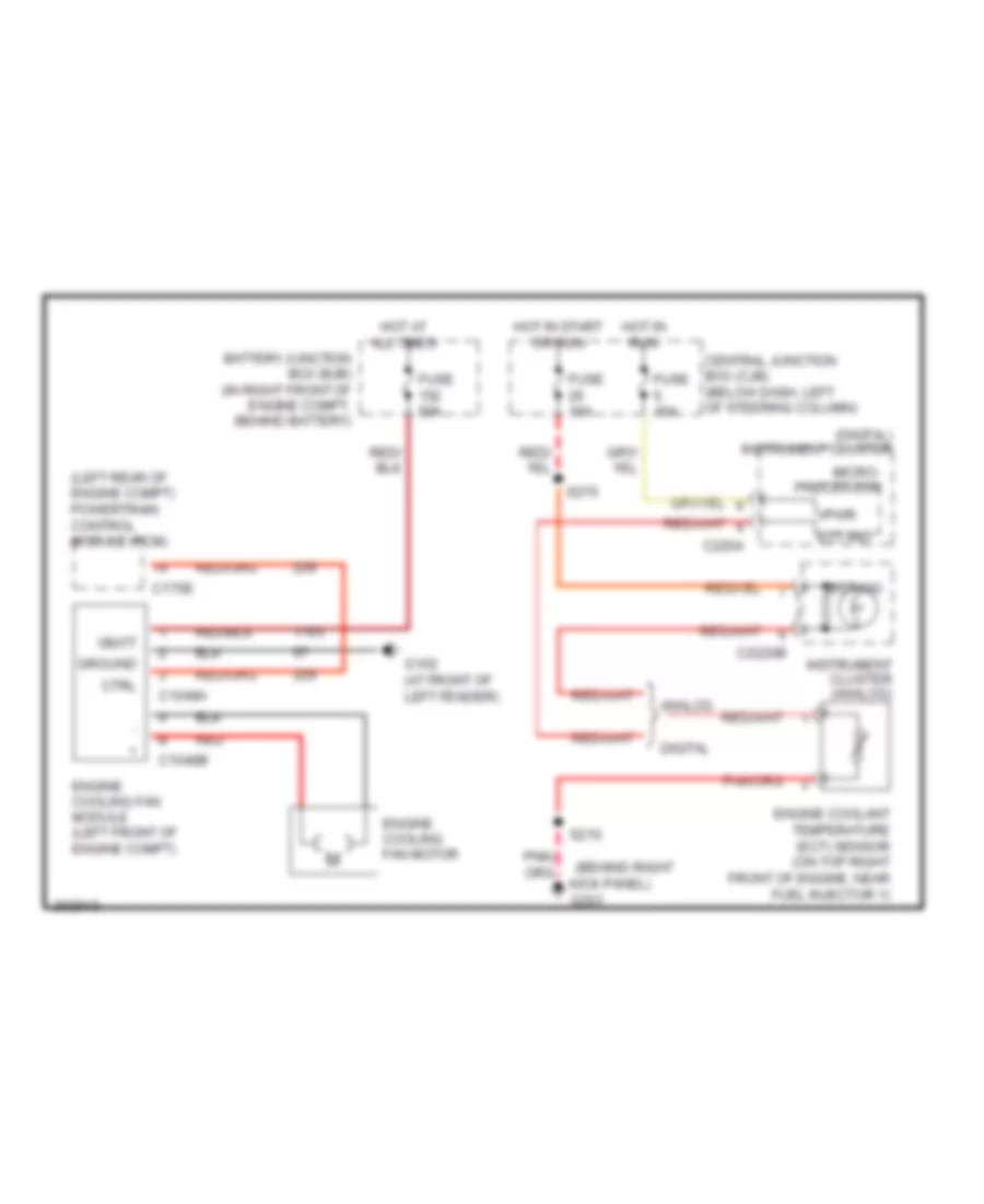
COOLING FAN
Cooling Fan Wiring Diagram for Mercury Grand Marquis GS 2005
List of elements for Cooling Fan Wiring Diagram for Mercury Grand Marquis GS 2005:
- (behind right
- (digital) instrument cluster
- (left rear of engine compt) powertrain control module (pcm)
- Analog
- Battery junction box (bjb) (in right front of engine compt, behind battery)
- C1048a
- C1048b
- C175e
- C220a
- C2220b
- Central junction box (cjb) (below dash, left of steering column)
- Ctrl
- Digital
- Ect ind
- Engine coolant temperature (ect) sensor (on top right front of engine, near fuel injector 1)
- Engine cooling fan module (left front of engine compt)
- Engine cooling fan motor
- Fuse 10a
- Fuse 50a
- G102 (at front of left fender)
- Ground
- Hot at all times
- Hot in run
- Hot in start or run
- Instrument cluster (analog)
- Kick panel) g201
- Micro- processor
- Red
- S210
- S276
- Vbatt
- Vpwr
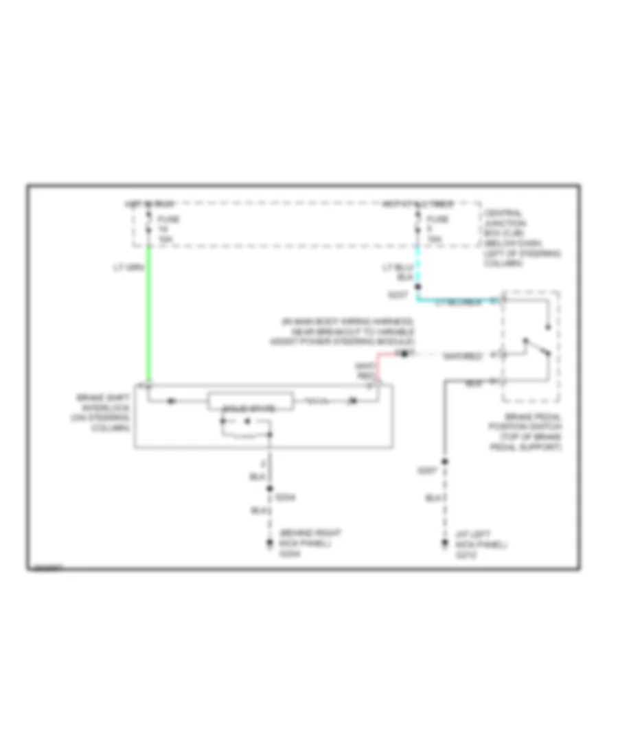
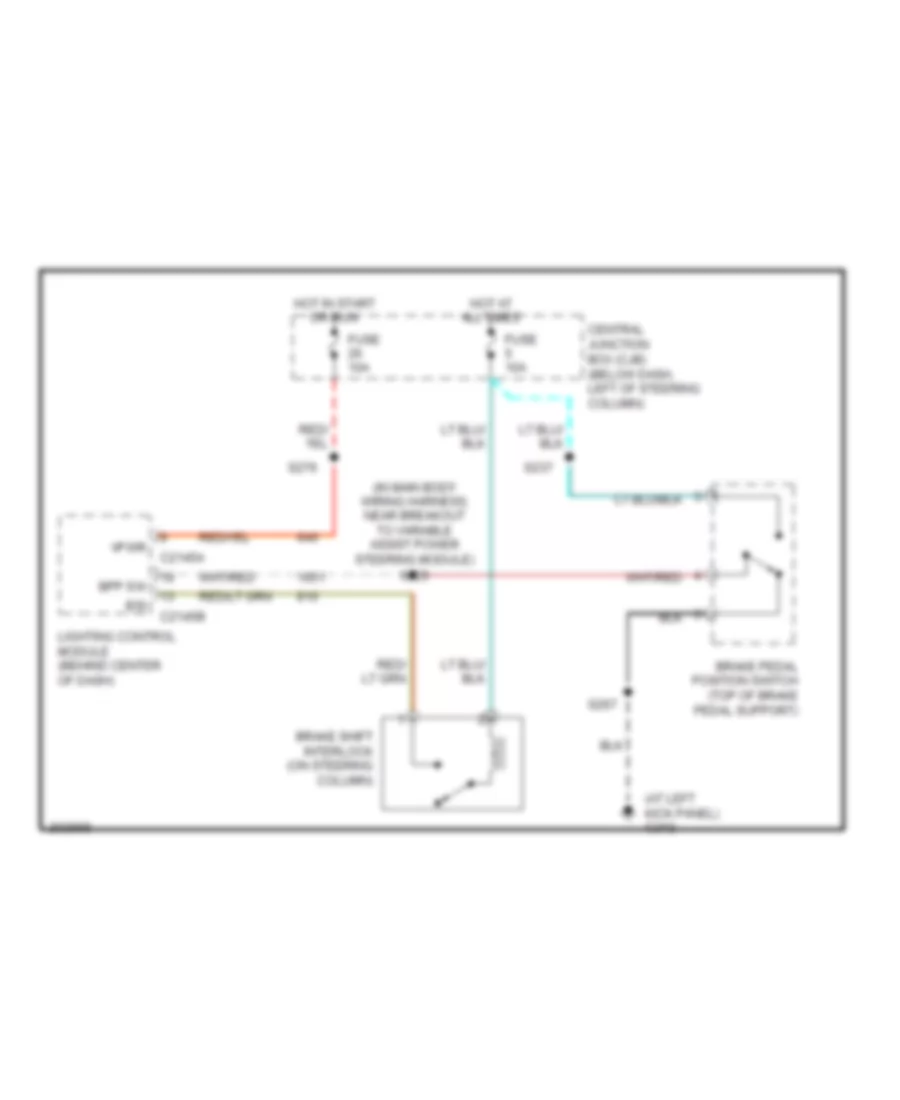
CRUISE CONTROL
Cruise Control Wiring Diagram for Mercury Grand Marquis GS 2005
List of elements for Cruise Control Wiring Diagram for Mercury Grand Marquis GS 2005:
- (in dash panel to headlamp junction harness, near breakout to pcm) s103
- (in main body wiring harness, near breakout to g212)
- Abs control module (at left front of engine compt)
- Accelerator pedal position sensor (under left side of dash)
- Air bag sliding contact (at base of steering column)
- Bpp sw
- Brake pedal position switch (top of brake pedal support)
- Brake shift interlock (on steering column)
- C175b
- C175e
- C175t
- C2145b
- C218a
- C218b
- C2330a
- C2330b
- C501a
- Central junction box (cjb) (below dash, left of steering column)
- Coast
- Deactivator sw
- Deactivator switch
- Driver door module (bottom front of left front door)
- Electronic throttle control (etc) motor (left side of engine)
- Etc motor +/-
- Fuse 10a
- G212 (at left kick panel)
- Hot at all times
- Illumination
- Interior lights system
- Lighting control module (behind center of dash)
- Off
- Oss sig
- Output shaft speed (oss) sensor (on left side of transmission)
- Powertrain control module (pcm) (left rear of engine compartment)
- Resume
- S147 (in engine control sensor & fuel charge wiring harness, near breakout to pcm)
- S225 (in main body wiring harness, near breakout to variable assist power steering module)
- S237
- S256
- S267
- S292
- S292 (in steering wheel control switch jumper harness)
- S293
- S295 (in steering wheel control switch jumper harness)
- Sensor 1 sig
- Sensor 2 sig
- Sensor 3 sig
- Set
- Set +
- Set -
- Sig rtn
- Steering wheel/speed control switch
- Throttle position sensor (tps) (on left side of engine)
- Tps sig 1
- Tps sig 2
- Vref
- W/ center console
- W/ steering wheel audio climate control switch
- W/o center console
- W/o steering wheel audio climate control switch
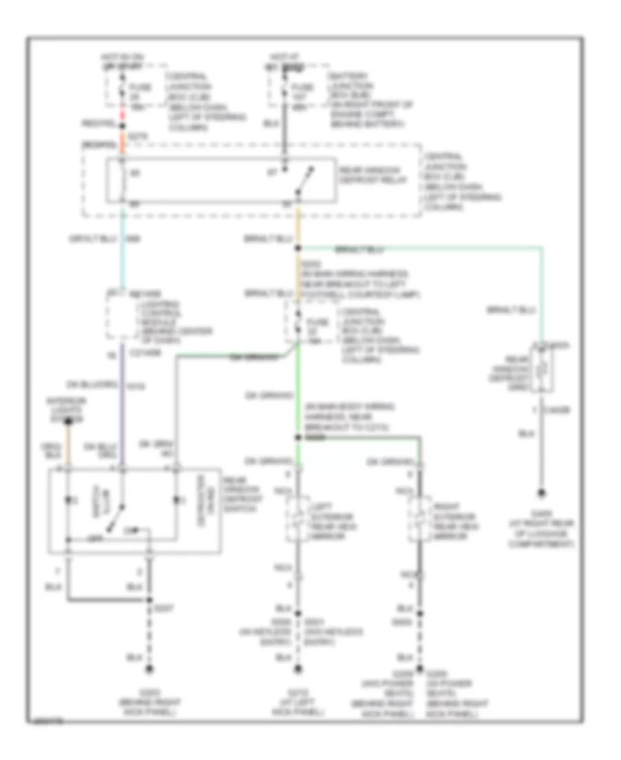
DEFOGGERS
Defoggers Wiring Diagram for Mercury Grand Marquis GS 2005
List of elements for Defoggers Wiring Diagram for Mercury Grand Marquis GS 2005:
- (in main body wiring harness, near breakout to c213) s228
- Battery junction box (bjb) (in right front of engine compt, behind battery)
- C2145b
- C402a
- C402b
- Central junction boc (cjb) (below dash, left of steering column)
- Central junction box (cjb) (below dash, left of steering column)
- Fuse 10a
- Fuse 40a
- G200 (w/ power seats) (behind right kick panel)
- G203 (behind right kick panel)
- G209 (w/o power seats) (behind right kick panel)
- G212 (at left kick panel)
- G400 (at right rear of luggage compartment)
- Hot at all times
- Hot in on or start
- Illum switch
- Interior lights system
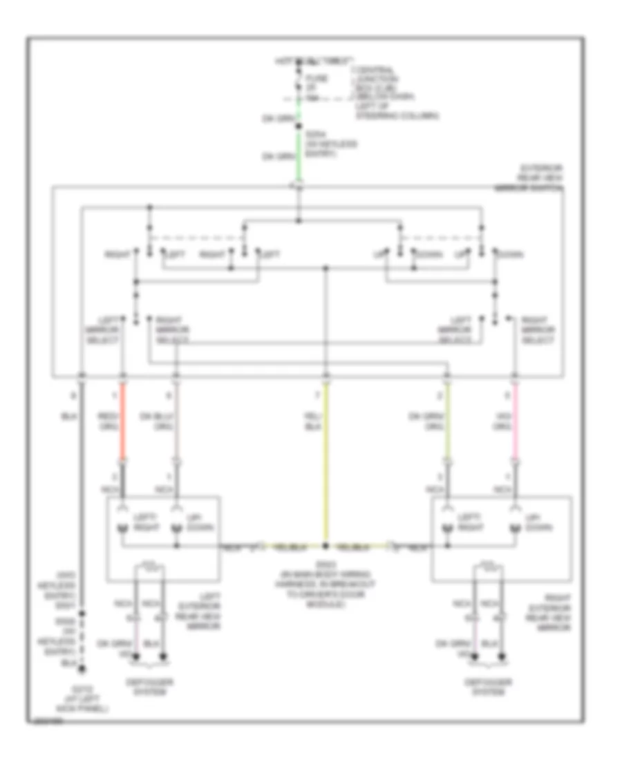
- Left exterior rear view mirror
- Lighting control module (behind center of dash)
- Nca
- Off
- On ind defroster
- Rear window defrost grid
- Rear window defrost relay
- Rear window defrost switch
- Right exterior rear view mirror
- S207
- S252 (in main wiring harness, near breakout to left footwell courtesy lamp)
- S276
- S500 (w/ keyless entry)
- S501 (w/o keyless entry)
- S600
ELECTRONIC POWER STEERING
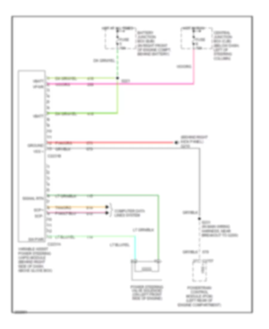
Electronic Power Steering Wiring Diagram, with Air Suspension for Mercury Grand Marquis GS 2005
List of elements for Electronic Power Steering Wiring Diagram, with Air Suspension for Mercury Grand Marquis GS 2005:
- Air suspension module (behind right side of dash, above glove box)
- Battery junction box (bjb) (in right front of engine compt, behind battery)
- C175t
- C2131a
- C2131b
- Central junction box (cjb) (below dash, left of steering column)
- Computer data lines system
- Fuse 10a
- G201 (behind right kick panel)
- Ground
- Hot at all times
- Hot in run
- Power steering valve solenoid (on left front side of engine)
- Powertrain control module (pcm) (left rear of engine compartment)
- S221
- S231 (in main wiring harness, near breakout to g200)
- Scp+
- Scp-
- Vbatt
- Vpwr
- Vss
- Vss (+)
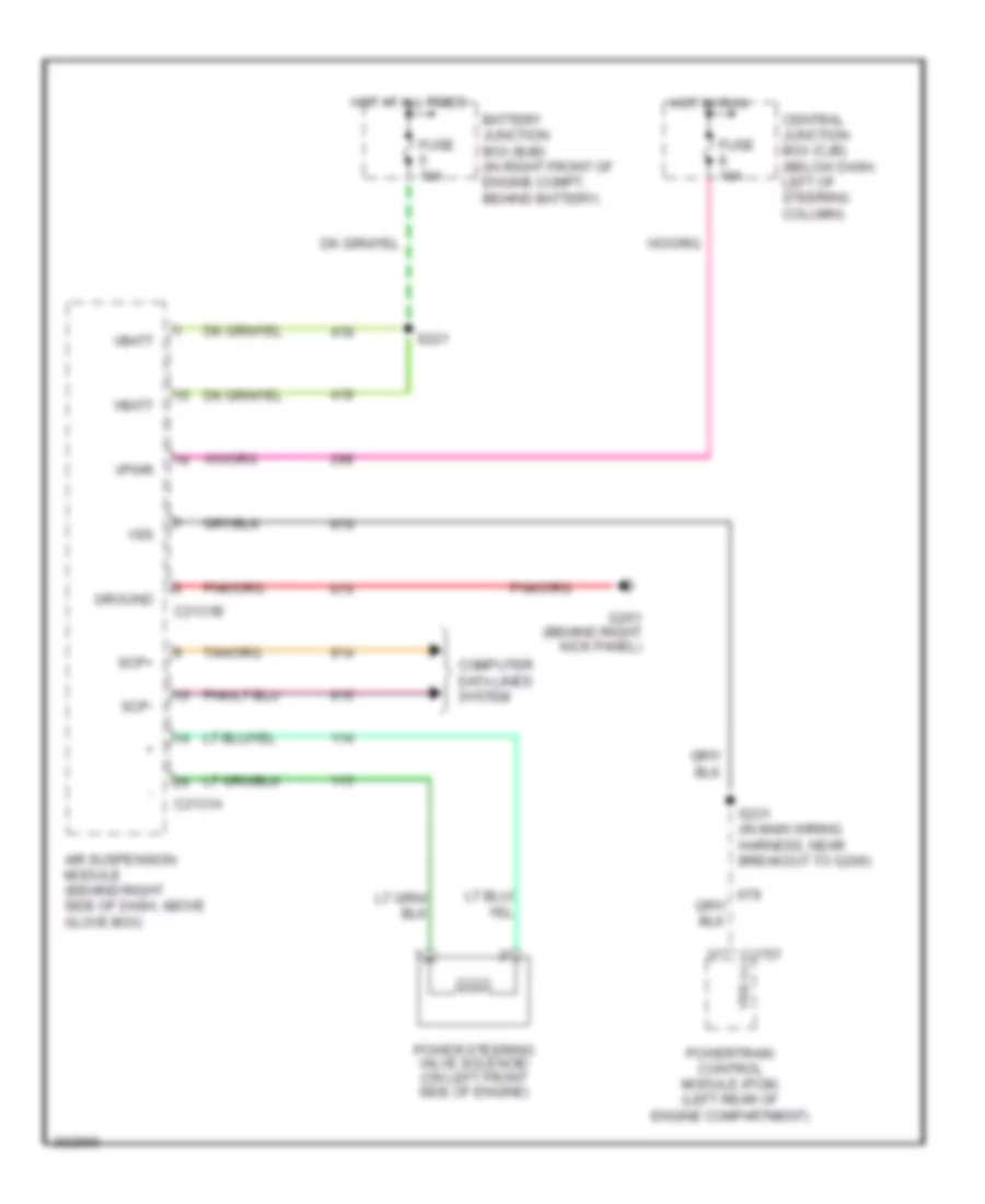
Electronic Power Steering Wiring Diagram, without Air Suspension for Mercury Grand Marquis GS 2005
List of elements for Electronic Power Steering Wiring Diagram, without Air Suspension for Mercury Grand Marquis GS 2005:
- (behind right kick panel) g210
- Battery junction box (bjb) (in right front of engine compt, behind battery)
- C175t
- C2231a
- C2231b
- Central junction box (cjb) (below dash, left of steering column)
- Computer data lines system
- Fuse 10a
- Ground
- Hot at all times
- Hot in run
- Power steering valve solenoid (on left front side of engine)
- Powertrain control module (pcm) (left rear of engine compartment)
- S221
- S231 (in main wiring harness, near breakout to g200)
- Scp+
- Scp-
- Signal rtn
- Sw pwr
- Variable assist power steering (vaps) module (behind right side of dash, above glove box)
- Vbatt
- Vpwr
- Vss +
ELECTRONIC SUSPENSION
Electronic Suspension Wiring Diagram for Mercury Grand Marquis GS 2005
List of elements for Electronic Suspension Wiring Diagram for Mercury Grand Marquis GS 2005:
- (at front of left fender) g105
- (behind center of dash) lighting control module
- (in main body wiring harness, near breakout to c423) s450
- (in right front of engine compt, behind battery) battery junction box (bjb)
- Air suspension compressor assembly (at left front side of engine compt)
- Air suspension compressor relay
- Air suspension disable switch
- Air suspension height sensor (under rear of vehicle attached to control arm)
- Air suspension indicator
- Air suspension module (behind right side of dash, above glove box)
- Analog cluster
- Battery junction box (bjb) (in right front of engine compt, behind battery)
- C175t
- C2131a
- C2131b
- C2145a
- C220b
- C2220a
- Central junction box (cjb) (below dash, left of steering column)
- Compressor
- Computer data lines system
- Digital
- Electronic power steering system
- Fuse 10a
- Fuse 30a
- G102 (at front of left fender)
- G210 (behind right kick panel)
- G405 (at rear center of luggage compartment)
- Hot at all times
- Hot in run
- Instrument cluster
- Left rear air spring solenoid valve (at left rear of vehicle)
- Nca
- Pnk
- Powertrain control module (pcm) (left rear of engine compt)
- Pwr
- Red
- Right rear air spring solenoid valve (at right rear of vehicle)
- S112
- S113
- S120
- S221
- S231 (w/ overhead console) (near breakout to g200)
- Scp+
- Scp-
- Sig rtn
- Vbatt
- Vent
- Vpwr
- Vss
ENGINE PERFORMANCE
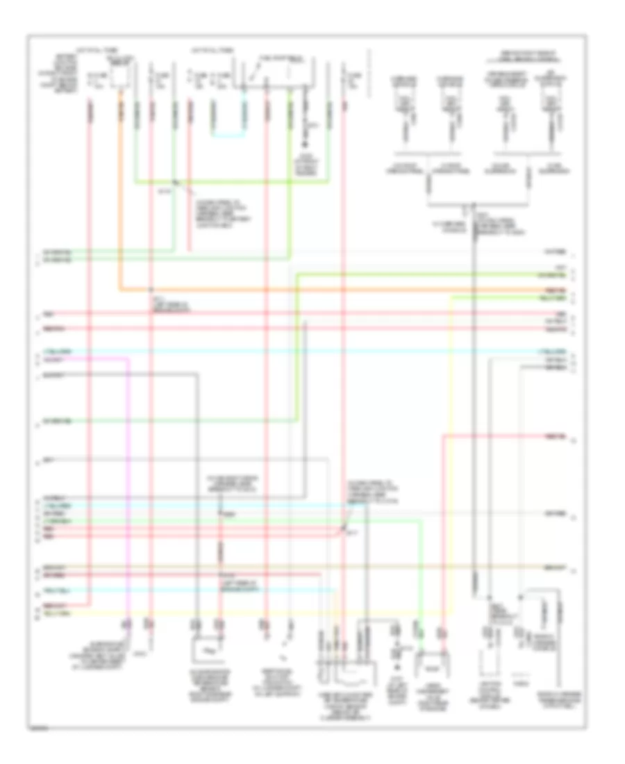
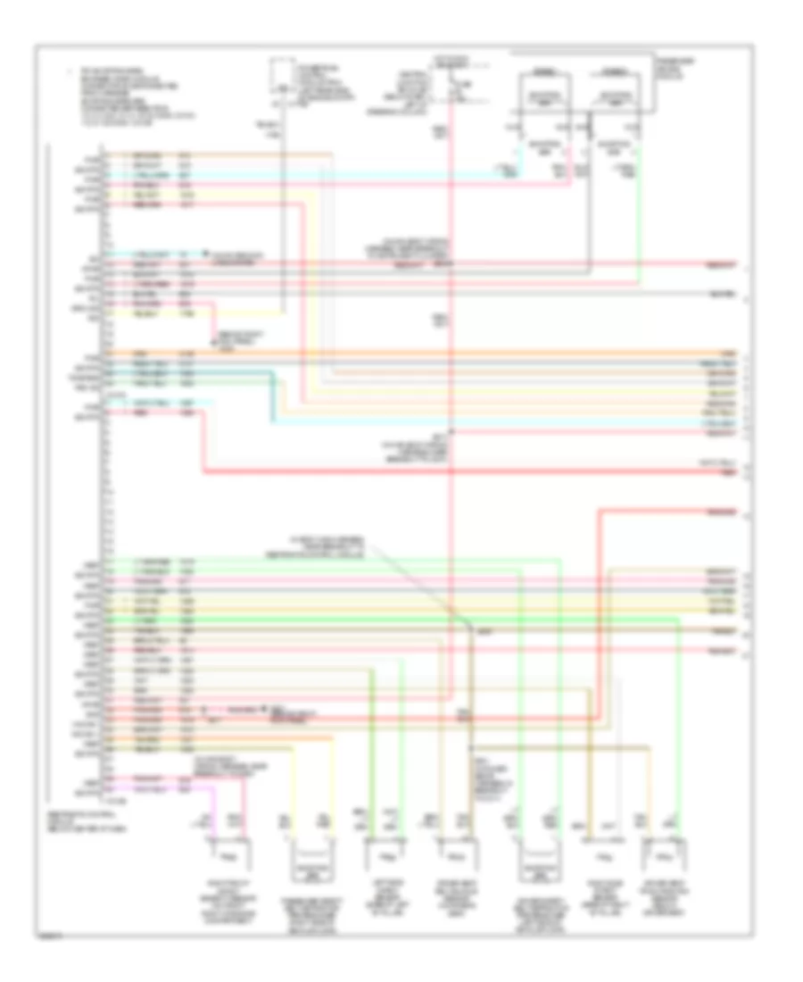
Engine Performance Wiring Diagram (1 of 5) for Mercury Grand Marquis GS 2005
List of elements for Engine Performance Wiring Diagram (1 of 5) for Mercury Grand Marquis GS 2005:
- A/c clutch rly
- A/c pre sen sig
- Abs ind
- Accelerator pedal position sensor (under left side of dash)
- Air conditioning system
- Anti-lock brakes system
- App sen sig 2
- App sen sig 3
- Apps sig 1
- Battery junction box (bjb) (in right front of engine compt, behind battery)
- Brk pedal sw
- C175b
- Can bus +
- Can bus -
- Central junction box (cjb) (below dash, left of steering column)
- Computer data lines system
- Cruise control system
- Evap can vent
- Feps
- Floor shifter (in center console)
- Fpm
- Fuel level data
- Fuse 10a
- Fuse 15a
- Fuse 30a
- G106 (at left rear of engine compt)
- G107 (at left rear of engine compt)
- G109 (at front of right fender)
- G110 (right side of engine)
- Gnd
- Heated pvc (on top right front of engine)
- Hot at all times
- Hot in run
- Hot in run or start
- Ign coils relay
- Instrument cluster system
- Intake sen sig
- Low charge sw
- Maf sens sig
- Maf/iat sen
- Mfp
- On/off ind sw
- Overdrive cancel switch
- Pcm power diode
- Pcm power relay
- Powertrain control module (pcm) (left rear of engine compt)
- Rdi
- Red
- Red/pnk
- Rtn sig
- S101
- S118
- S121
- S157
- S164
- S276
- Sig rtn
- Starter relay
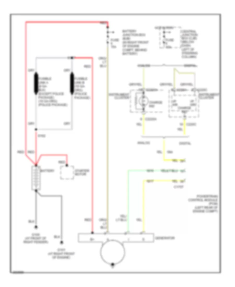
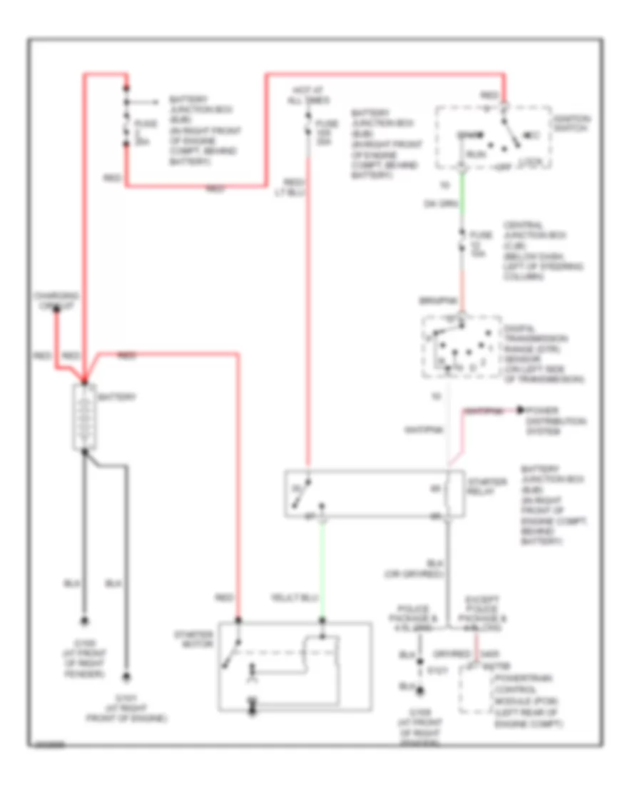
- Starting/charging system
- Temp sens sig
- Traction ctrl ind
- Trans ctrl sw
- Vapor valve
- Vbatt
- Vpwr
- Vref
- W/ center console
- W/o center console
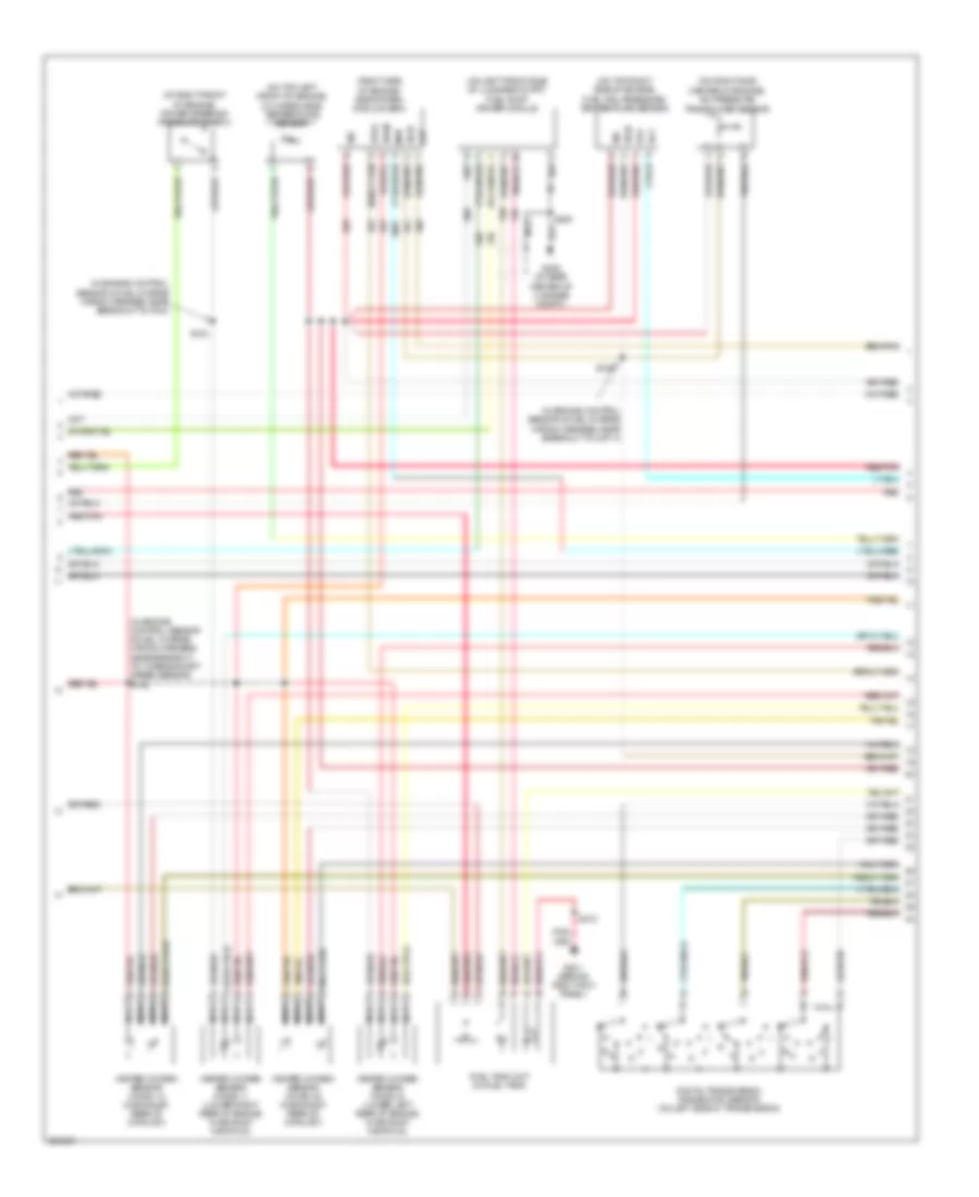
Engine Performance Wiring Diagram (2 of 5) for Mercury Grand Marquis GS 2005
List of elements for Engine Performance Wiring Diagram (2 of 5) for Mercury Grand Marquis GS 2005:
- (behind right side of dash, above glove box)
- (in dash panel to headlamp junction
- (in dash panel to headlamp junction harness, near breakout to battery junction box)
- (in main body wiring harness, near breakout to g212)
- (left rear of engine compt)
- A/c clutch relay
- A/c evaporator discharge air temperature sensor (right side rear engine compt)
- Air suspension module
- Battery junction box (bjb) (in right front of engine compt, behind battery)
- C2131b
- C2145b
- C220a
- C2231b
- C290a
- C930
- Ends in harness console
- Ends in harness passenger side in foot well
- Evaporative emission (evap) canister vent valve (in center rear of luggage compt)
- Fuel pump relay
- Fuse 10a
- Fuse 15a
- Fuse 20a
- G107 (at left rear of engine compt)
- G109 (at front of right fender)
- Harness, near breakout to c1019)
- Hot at all times
- Inertia fuel shut-off (ifs) switch (in luggage compt, on left support)
- Lighting control module (behind center of dash)
- Mass air flow/intake air temperature (maf/iat) sensor (behind air cleaner assembly)
- Overhead console
- Radio
- Red
- Red/pnk
- S111 (left rear of engine compt)
- S117
- S118
- S119
- S121
- S130
- S231 (in main wiring harness, near breakout to g200)
- S247 (near breakout to c410)
- S256
- Vapor management valve (right rear of engine)
- Variable assist power steering (vaps) module
- Vhcl spd input
- W/ air suspension
- W/ overhead console
- W/ roof opening panel
- W/o air suspension
- W/o roof opening panel
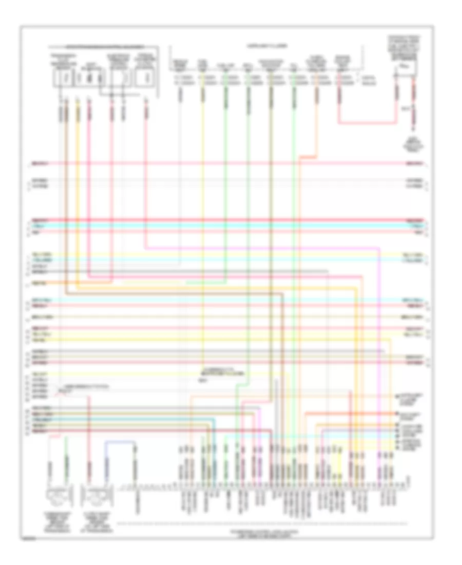
Engine Performance Wiring Diagram (3 of 5) for Mercury Grand Marquis GS 2005
List of elements for Engine Performance Wiring Diagram (3 of 5) for Mercury Grand Marquis GS 2005:
- (at right front of engine) power steering pressure switch
- (in engine control sensor & fuel charge wiring harness, near breakout to cop 4)
- (in engine control sensor & fuel charge wiring harness, near breakout to pcm)
- (in engine control sensor & fuel charge wiring harness, near breakout to turbine shaft speed sensor) s146
- (on left front side of luggage compt) fuel pump driver module
- (on right side center of engine) a/c pressure transducer sensor
- (on top left front of engine) cylinder-head temperature sensor
- (on top right side of engine) fuel rail pressure/ temperature sensor
- (right side of engine) egr system module (esm)
- Digital transmission range (dtr) sensor (on left side of transmission)
- Dpfe
- Evp
- Frp
- Frt
- Fuel tank unit (in fuel tank)
- G201 (behind right kick panel)
- G406 (at rear center of luggage compt)
- Heated oxygen sensor (ho2s) 11 (lower right rear of engine, in exhaust manifold)
- Heated oxygen sensor (ho2s) 12 (in exhaust, rear of catalyst)
- Heated oxygen sensor (ho2s) 21 (lower left rear of engine, in exhaust manifold)
- Heated oxygen sensor (ho2s) 22 (in exhaust, rear of catalyst)
- Map
- Nca
- R n
- Red
- Red/pnk
- S123
- S126
- S210
- S405
- Sig
- Vpwr
- Vref
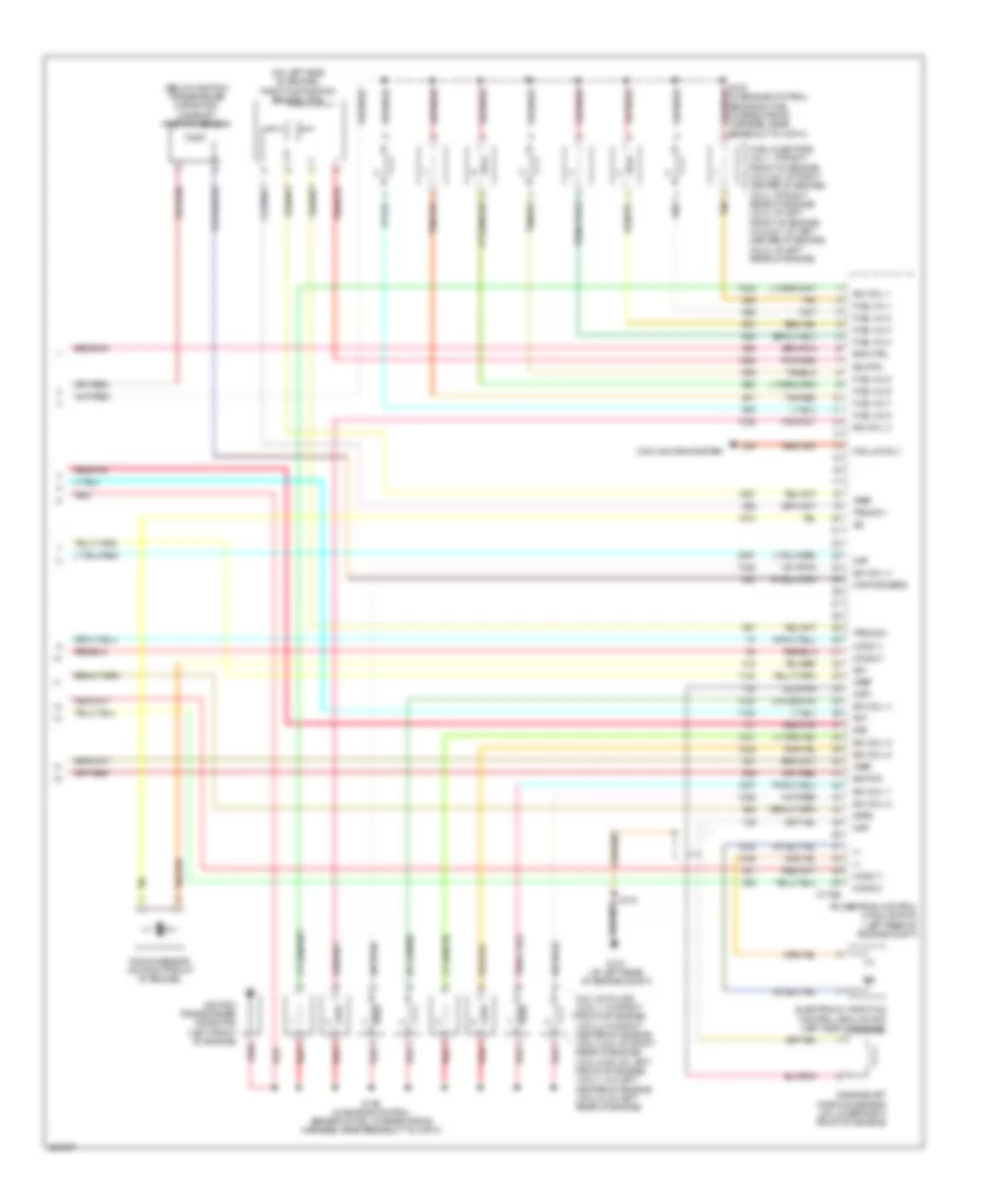
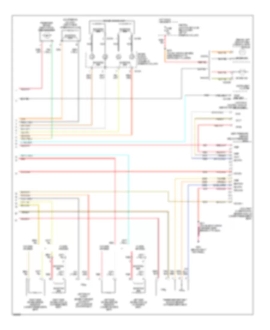
Engine Performance Wiring Diagram (4 of 5) for Mercury Grand Marquis GS 2005
List of elements for Engine Performance Wiring Diagram (4 of 5) for Mercury Grand Marquis GS 2005:
- (in breakout to instrument cluster)
- (near breakout to pcm) s147
- (top right front of engine, near fuel injector 1) engine coolant temperature (ect) sensor
- 4r70w transmission control solenoids
- Analog
- Anti-theft ind
- Anti-theft system
- Battery ind
- C175t
- C220a
- C220c
- C2220a
- C2220b
- Check guage (or) fail-safe cool ind
- Check ind
- Computer data lines system
- Cruise ind
- Cylinder head
- Digital
- Electronic pressure control solenoid
- Eng vacuum
- Engine coolant temp input
- Epcs ctrl
- Etcil ind
- Fuel cap ind
- Fuel level ind
- Fuel pump sig
- G201 (behind right kick panel)
- Gen comm
- Ho2s 12
- Ho2s 22
- Instrument cluster
- Instrument cluster system
- Malfunction indicator input
- Oss sensor
- Output shaft speed (oss) sensor (on left side of transmission)
- Overdrive ind
- Powertrain control module (pcm) (left rear of engine compt)
- Red
- S202
- S210
- Scp bus +
- Scp bus -
- Shift sol a
- Shift sol b
- Shift solenoids
- Sig rtn
- Ssa
- Ssb
- Starting/ charging system
- Tcc sol
- Tcil ind
- Tft sens sig
- Torque converter clutch solenoid
- Tr1
- Tr2
- Tr3a
- Tr4
- Transmission fluid temperature sensor
- Tss sen sig
- Turbine shaft speed (tss) sensor (left side of transmission)
- Veh spd sig
- Vehicle speed input
Engine Performance Wiring Diagram (5 of 5) for Mercury Grand Marquis GS 2005
List of elements for Engine Performance Wiring Diagram (5 of 5) for Mercury Grand Marquis GS 2005:
- (below ignition transformer capacitor) camshaft position sensor
- (on left side of engine) throttle position sensor (tps)
- +/-
- C175e
- Cam pos sens
- Ckp+
- Ckp-
- Coil on plugs (coil 1: on right front of engine) (coil 2: on right center of engine) (coil 3 & 4: on right rear of engine) (coil 5 & 6: on left front of engine) (coil 7: on left center of engine) (coil 8: on left rear of engine)
- Cooling fans system
- Crankshaft position sensor (on lower right front of engine)
- Dpfe
- Electronic throttle control (etc) motor (left side of engine)
- Evr ctrl
- Fan low rly
- Frp
- Frt
- Fuel inj 1
- Fuel inj 2
- Fuel inj 3
- Fuel inj 4
- Fuel inj 5
- Fuel inj 6
- Fuel inj 7
- Fuel inj 8
- Fuel injectors (inj 1: at right front of engine) (inj 2 & 3: at right center of engine) (inj 4: at right rear of engine) (inj 5: at left front of engine) (inj 6 & 7: at left center of engine) (inj 8: at left rear of engine)
- G107 (at left rear of engine compt)
- Ho2s 11
- Ho2s 21
- Ign coil 1
- Ign coil 2
- Ign coil 3
- Ign coil 4
- Ign coil 5
- Ign coil 6
- Ign coil 7
- Ign coil 8
- Ignition transformer capacitor (left front of engine)
- Knock sensor (on right front of engine)
- Ks+
- Ks-
- Map
- Powertrain control module (pcm) (left rear of engine compt)
- Red
- Red/pnk
- S118
- S136 (in engine control sensor & fuel charge wiring harness, near breakout to cop 4)
- Sig rtn
- Tan
- Tan/red
- Tps sig 1
- Tps sig 2
- Vref
EXTERIOR LIGHTS
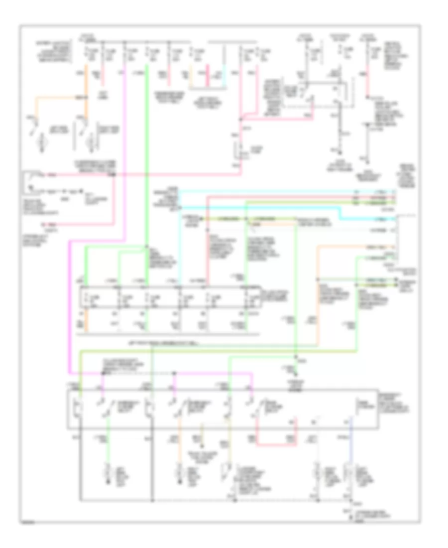
Accessory Lamps Wiring Diagram, with Police Option for Mercury Grand Marquis GS 2005
List of elements for Accessory Lamps Wiring Diagram, with Police Option for Mercury Grand Marquis GS 2005:
- (at rear center of luggage compt) g406
- (behind center
- (in emergency jumper wiring harness, near breakout for g411) s460
- (in luggage compt wiring harness, near breakout to c405) s433
- (in main wiring harness, near breakout to passenger air bag deactivation indicator)
- (near breakout to passive anti-theft transceiver) s273
- (not used)
- 10a
- B6 c2319
- Battery junction box (bjb) (in right front of engine compt, behind battery)
- C202a
- C202c
- C2145c
- C2319
- C3257a
- C4170a
- C4170b
- Central junction box (cjb) (below dash, left of steering column)
- Emergency flasher relay 1
- Emergency flasher relay 2
- Emergency flasher relay block (in left rear of luggage compt)
- Ends in harness (center console)
- Exterior lamps circuit
- Fuse 10a
- Fuse 20a
- Fuse 25a
- Fuse 40a
- Fuse 50a
- Fuse b1 15a
- Fuse b2 15a
- Fuse b3 15a
- Fuse b4 2a
- Fuse b5 2a
- Fuse b6 2a
- G109 (at front of right fender)
- G403 (behind right rear seat)
- G411 (in luggage compt)
- Hot at all times
- Hot in run or acc
- Inline fuse
- Interior lights system
- Left front ends harness (foot-well)
- Left rear police flasher lamp
- Left rear police tray lamp
- Left side spot lamp
- Lighting control
- Luggage compartment lid release solenoid (on center rear of luggage compt lid)
- Module
- Multi-function switch
- Of dash)
- Passenger side ends harness (foot-well)
- Pnk
- Police option fuse holder (in glove box)
- Police power relay
- Rear flasher
- Rear flasher relay
- Rear police auxiliary junction box (behind bottom center of rear seats)
- Red
- Right rear police flasher lamp
- Right rear police tray lamp
- Right side spot lamp
- S110
- S121
- S211 (near breakout to passenger air bag module)
- S222
- S224
- S243 (in main wiring harness, in breakout to instrument cluster)
- S290
- S403
- S406 (in main body wiring harness, near breakout to c423)
- S422 (in main body wiring harness, near breakout to c423)
- S465
- Strobe/light bar control switches
- Trunk air circulation fan motor (in luggage compt)
- Trunk, tailgate fuel doors system
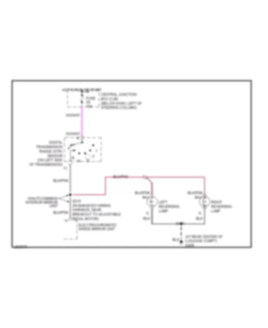
Back-up Lamps Wiring Diagram for Mercury Grand Marquis GS 2005
List of elements for Back-up Lamps Wiring Diagram for Mercury Grand Marquis GS 2005:
- (at rear center of luggage compt) g406
- Central junction box (cjb) (below dash, left of steering column)
- Digital transmission range (dtr) sensor (on left side of transmission)
- Electrochromatic inside mirror unit
- Fuse 10a
- Hot in run or start
- Left reversing lamp
- Right reversing lamp
- S420
- W/auto-dimming interior mirror unit
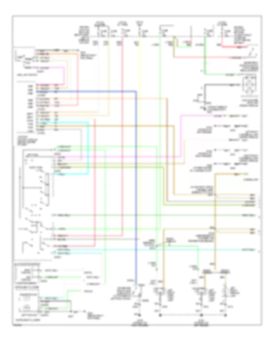
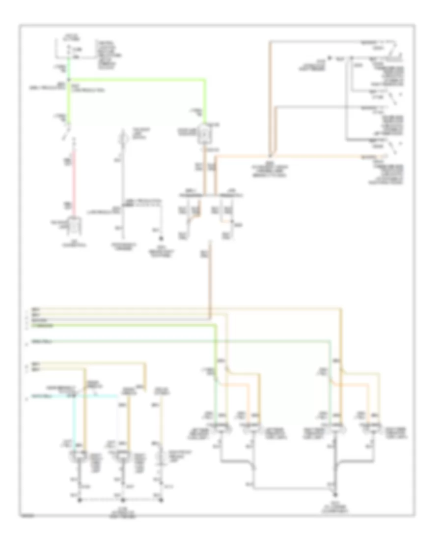
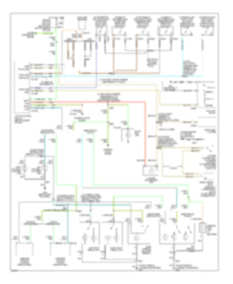
Exterior Lamps Wiring Diagram, without Police Option (1 of 2) for Mercury Grand Marquis GS 2005
List of elements for Exterior Lamps Wiring Diagram, without Police Option (1 of 2) for Mercury Grand Marquis GS 2005:
- (at right rear of luggage compt) g401
- (behind right kick panel)
- (in main body wiring harness, near breakout to c410) s427
- (near breakout to ambient air temperature sensor)
- (near breakout to c1010) s116
- Analog
- Auto
- Battery junction box (bjb) (in right front of engine compt, behind battery)
- Brake pedal position switch (top of brake pedal support)
- C202a
- C202c
- C205a
- C2145a
- C2145b
- C2145c
- C220c
- C2220a
- C2220b
- C526a
- C526b
- Central junction box (cjb) (below dash, left of steering column)
- Crown victoria
- Digital
- Driver side front door ajar switch (at top rear of left front door)
- Fuse 10a
- Fuse 15a
- Fuse 20a
- G102 (at front of left fender)
- G109 (at front of right fender)
- G203
- G203 (behind right kick panel)
- G406 (at rear center of luggage compt)
- Grand marquis
- Head
- High mounted stoplamp (grand marquis)
- Hot at all times
- Hot in run
- Instrument cluster
- Left front cornering lamp (grand marquis)
- Left front park/ turn lamp
- Left front parking lamp
- Left turn
- Left turn ind
- License lamp
- Lighting control module (behind center of dash)
- Main light switch
- Maj
- Microprocessor
- Min
- Multi-function switch
- Nca
- Off
- Park
- Pwr
- Red
- Right front cornering lamp (grand marquis)
- Right turn
- Right turn ind
- S107
- S108
- S109
- S112
- S159
- S201
- S207
- S238
- S402
- S420
- Vbatt
- Vpwr
- Vref
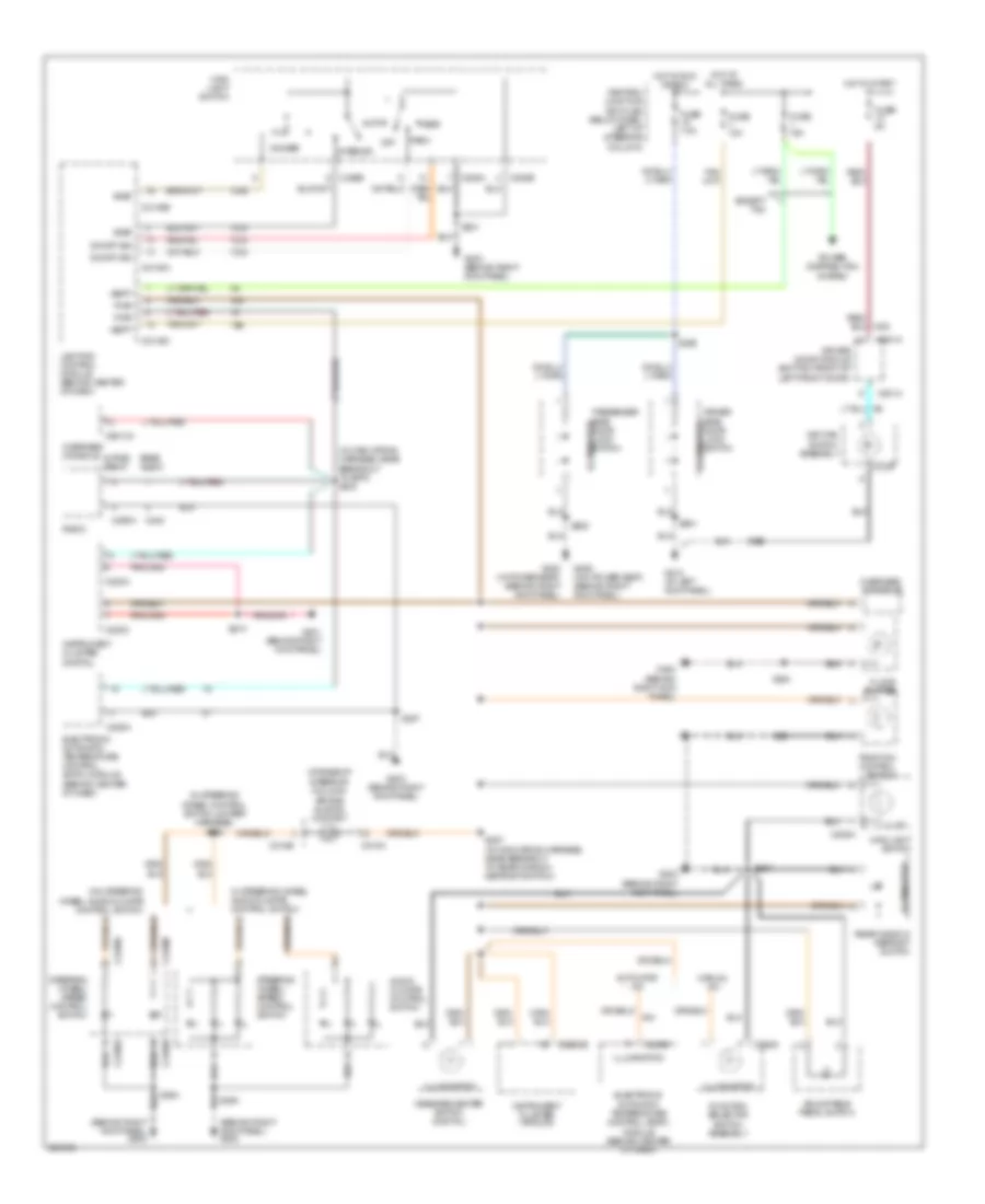
Exterior Lamps Wiring Diagram, without Police Option (2 of 2) for Mercury Grand Marquis GS 2005
List of elements for Exterior Lamps Wiring Diagram, without Police Option (2 of 2) for Mercury Grand Marquis GS 2005:
- (at front of right fender)
- (behind right kick panel)
- (early production) s281
- (near breakout to c1019) s115
- (no connection)
- (roof ends in harness)
- C2212a
- C2212b
- C602a
- C602b
- C715a
- C715b
- C820a
- C820b
- Central junction box (cjb) (below dash, left of steering column)
- Crown victoria
- Door ajar indicator
- Driver side rear door ajar switch (at rear of left rear door)
- Early
- Fuse 15a
- G109
- G109 (at front of right fender)
- G204
- G410 (in luggage compartment)
- Grand marquis
- Hot at all times
- Late
- Left rear park/stop/ turn lamp 1
- Left rear park/stop/ turn lamp 2
- Maj
- Min
- Passenger side front door ajar switch (at top rear of right front door)
- Passenger side rear door ajar switch (at rear of right rear door)
- Production
- Right front park/ turn lamp
- Right front parking lamp
- Right rear park/stop/ turn lamp 1
- Right rear park/stop/ turn lamp 2
- S107
- S114
- S158
- S204 (late production)
- S226
- S227 (late production)
- S238
- S259 (in main body wiring harness, near breakout to g200)
- S282 (early production)
- Taxi roof lamp
- Taxi roof lamp switch
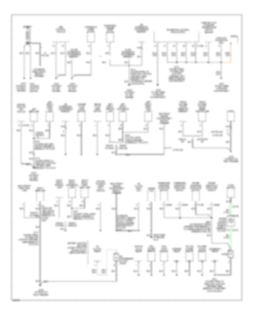
GROUND DISTRIBUTION
Ground Distribution Wiring Diagram (1 of 4) for Mercury Grand Marquis GS 2005
List of elements for Ground Distribution Wiring Diagram (1 of 4) for Mercury Grand Marquis GS 2005:
- (in dash panel to headlamp junction harness, near breakout to c1010)
- (in engine control sensor & fuel charge wiring harness, near breakout to c192) s157
- (right side of engine) g110
- A/c clutch field coil
- A/c clutch relay
- A/c compressor clutch diode
- Abs control module
- Accessory relay
- Air bag sliding contact (base of steering column)
- Air suspension compressor assembly
- Automatic a/c
- Battery
- Battery junction box (bjb) (in right front of engine compt, behind battery)
- Blower motor relay
- Brake fluid level switch
- C1048a
- C175b
- C217b
- C218a
- C218b
- C526b
- C602b
- C715b
- C820b
- Crown victoria
- Data link connector (dlc)
- Daytime running lamps (drl) module
- Diode
- Driver side front door ajar switch
- Driver side rear door ajar switch
- Engine cooling fan module
- Front blower motor resistor assembly
- Front blower motor speed controller
- Fuel pump relay
- G100 (at front of right fender)
- G101 (at right front of engine)
- G102 (at front of left fender)
- G103 (at front of left fender)
- G104 (at front of left fender)
- G105 (at front of left fender)
- G106 (at left rear of engine compartment)
- G107 (at left rear of engine compartment)
- G108 (at front of right fender)
- G109 (at front of right fender)
- Grand marquis
- Heated pvc
- Horn
- Horn switch
- Ignition coils relay
- Lead wiring harness, in breakout to c1046) s158
- Left front cornering lamp
- Left front engine compartment ends in harness
- Left front park/ turn lamp
- Left front parking lamp
- Left headlamp
- Low brand radio trunk ends in harness
- Manual a/c
- Mass air flow/ intake air temperature (maf/iat) sensor
- Nca
- Passenger side front door ajar switch
- Passenger side rear door ajar switch
- Pcm power relay
- Police power relay
- Powertrain control module (pcm)
- Pump motor)
- Right front cornering lamp
- Right front engine compartment ends in harness
- Right front park/ turn lamp
- Right front park/turn lamp
- Right front parking lamp
- Right headlamp
- S107 (in right turn lamps wiring harness, in breakout to c1019)
- S108 (in turn lamps wiring harness, in breakout to c1010)
- S114 (in dash panel to headlamp junction harness, near breakout to c1019)
- S118 (in dash panel to headlamp junction harness, left rear of engine compartment)
- S121 (in dash panel to headlamp junction harness, near breakout to battery junction box)
- S159 (in headlamp lead wiring harness, in breakout to c1047)
- S238 (in main body wiring harness, near breakout to variable assist power steering module)
- Shield
- Starter relay
- W/ air suspension compressor assembly
- W/ police
- W/o air suspension compressor assembly
- W/o police
- Washer fluid level switch
- Windshield washer pump motor
- Windshield wiper motor
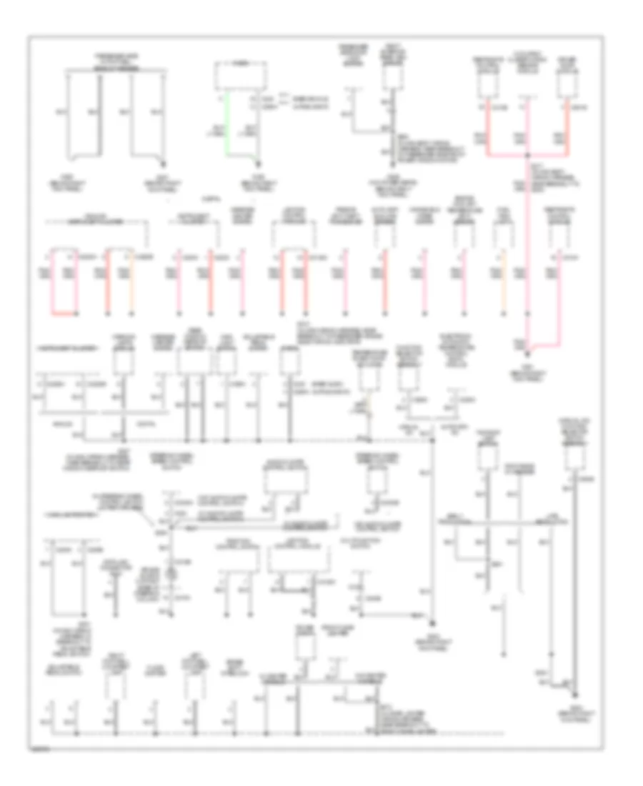
Ground Distribution Wiring Diagram (2 of 4) for Mercury Grand Marquis GS 2005
List of elements for Ground Distribution Wiring Diagram (2 of 4) for Mercury Grand Marquis GS 2005:
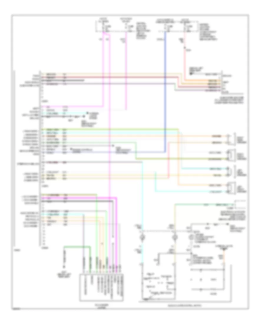
- (alpine, sanyo)
- (analog) instrument cluster
- (base audio)
- (in steering wheel control switch jumper harness)
- (manual a/c) function selector switch assembly
- (w/ audio/climate control switch)
- (w/o audio/climate control switch)
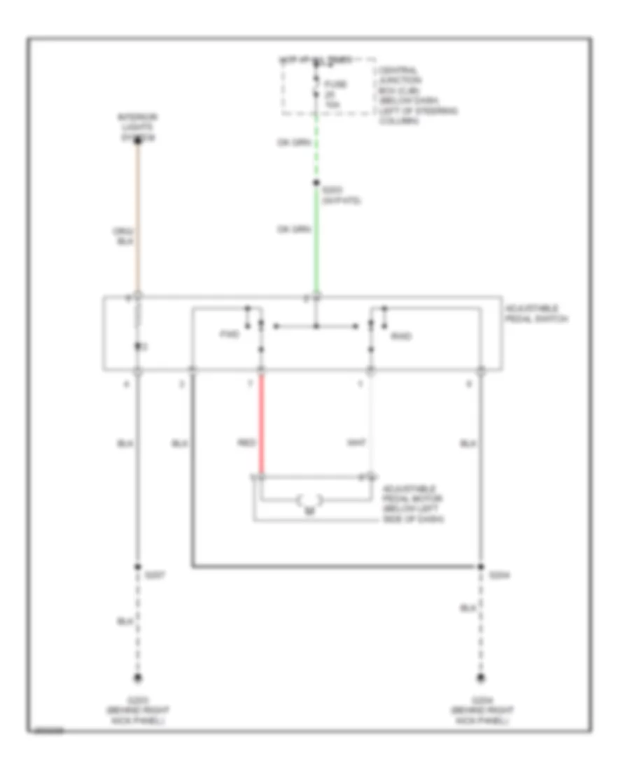
- Adjustable pedal switch
- Air bag sliding contact (base of steering column)
- Alpine, sanyo
- Analog
- Audio/climate control switch
- Autolamp/ sunload sensor
- Automatic a/c
- Base vehicle
- Brake shift interlock
- C202b
- C203
- C205a
- C205b
- C2145a
- C2145c
- C218a
- C218b
- C220a
- C220c
- C2220a
- C2220b
- C228a
- C2330a
- C2330b
- C240
- C290a
- C294b
- C294d
- C310a
- C310b
- C501b
- Data link connector (dlc)
- Digital
- Driver door module
- Early production
- Electronic automatic temperature control (eatc) module
- Engine coolant temperature (ect) sensor
- Floor shifter
- Front cigar lighter
- Fuel tank unit
- Function selector switch assembly
- G201 (behind right kick panel)
- G202 (behind right kick panel)
- G203 (behind right kick panel)
- G204 (behind right kick panel)
- G205 (behind right kick panel)
- G207 (behind right kick panel)
- G209 (w/o power seats) (behind right kick panel)
- Instrument cluster
- Late production
- Left footwell courtesy lamp
- Lighting control module
- Main light switch
- Manual a/c
- Message center switch
- Multifunction switch
- Nca
- Occupant classification sensor module
- Passenger side door lock switch
- Passenger side in footwell ends in harness
- Passive anti-theft transceiver
- Power point
- Radio
- Rear window defrost switch
- Restraints control module
- Right exterior rear view mirror
- Right footwell courtesy lamp
- Roof ends in harness
- S201 (in main wiring harness, in breakout to adjustable pedal switch)
- S204
- S207 (in main wiring harness, near breakout to rear window defrost switch)
- S210 (in main wiring harness, near breakout to passenger air bag deactivation indicator)
- S212 (in cigar lighter wiring harness, near breakout to front cigar lighter)
- S217 (in main body wiring harness, near breakout to g200)
- S281
- S294
- S600 (in main body wiring harness, near breakout to passenger side front power window motor)
- Steering wheel/ speed control switch
- Taxi roof lamp switch
- Temperature blend door actuator
- Traction control switch
- W/ audio/climate control switch
- W/ center console
- W/o audio/climate control switch
- W/o center console
- Warning lamps module
- Windshield wiper motor
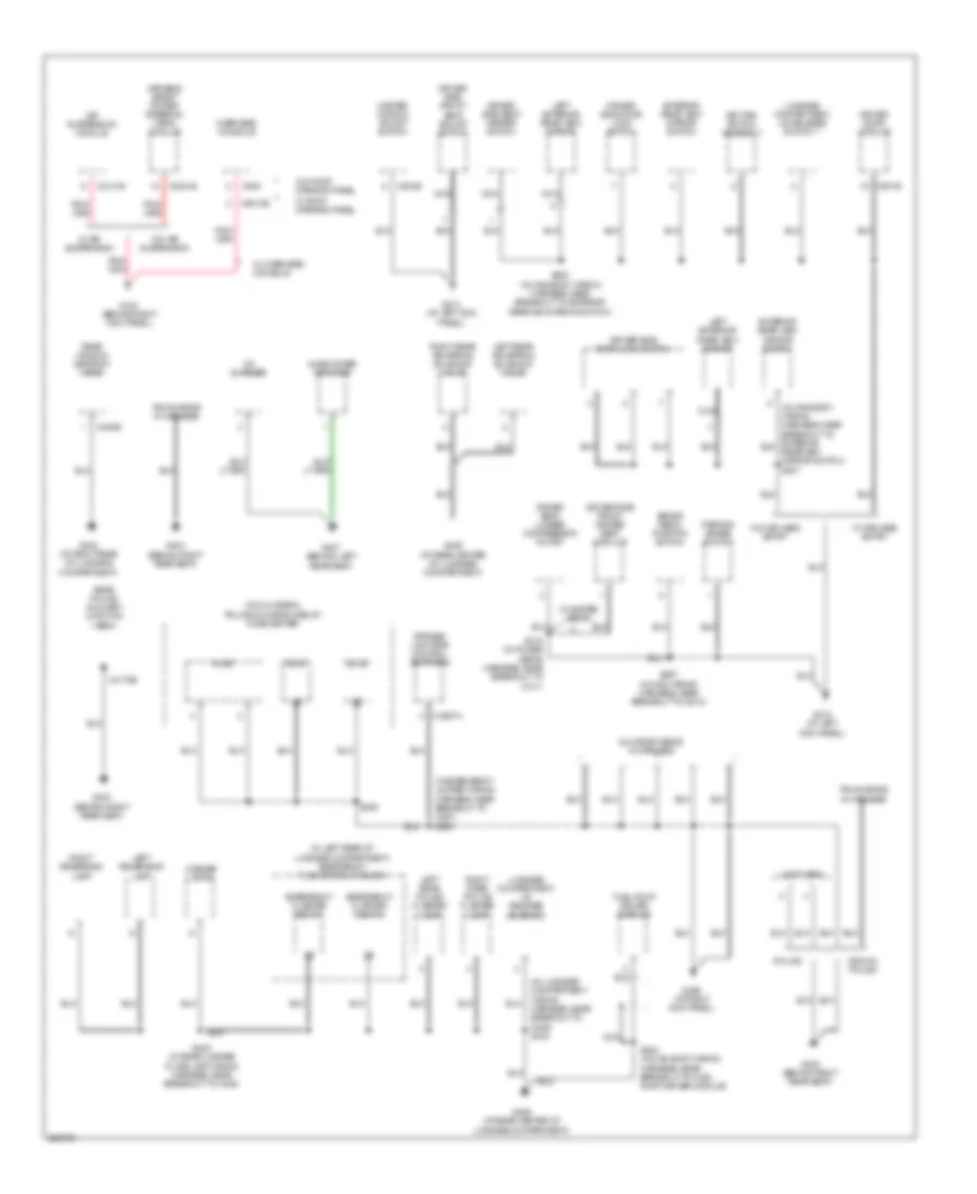
Ground Distribution Wiring Diagram (3 of 4) for Mercury Grand Marquis GS 2005
List of elements for Ground Distribution Wiring Diagram (3 of 4) for Mercury Grand Marquis GS 2005:
- (in emergency jumper wiring harness, near breakout to c291) s299
- (in glove box) police glove box relay/ fuse center
- (in left rear of luggage compartment) emergency flasher relay block
- (in luggage compartment wiring harness, near breakout to c405) s403
- Air suspension module
- Brake pedal position switch
- C2131b
- C2231b
- C3257a
- C402b
- C4170b
- C501b
- C504b
- C9013b
- C930
- Cd changer
- Crown police
- Driver door module
- Driver seat lumber compressor motor
- Driver side door lock switch
- Driver side front heated seat module
- Driver side front seat adjust switch
- Driver side seat heater switch
- Emergency flasher relay 1
- Emergency flasher relay 2
- Exterior rear view mirror switch
- Fuel pump driver module
- G206 (at right kick panel)
- G210 (behind right kick panel)
- G212 (at left kick panel)
- G213 (at left kick panel)
- G400 (at right rear of luggage compartment)
- G402 (behind right rear seat)
- G403 (behind right rear seat)
- G404 (behind right rear seat)
- G405 (at rear center of luggage compartment)
- G406 (at rear center of luggage compartment)
- G407 (behind left rear seat)
- Glove box ends in harness
- Key pad switch assembly
- Left exterior rear view mirror
- Left rear air spring solenoid valve
- Left rear police flasher lamp
- Left reversing lamp
- License lamps
- Luggage compartment lid release solenoid
- Luggage compartment lid release switch 1
- Master window adjust switch
- Nca
- Not used
- Overhead console
- Parking brake switch
- Police
- R2.a1
- R2.a4
- R2.a6
- Rear police auxiliary junction box
- Rear window defrost grid
- Right rear air spring solenoid valve
- Right rear police flasher lamp
- Right reversing lamp
- S267 (in main wiring harness, near breakout to g212)
- S285
- S315 (in power seats harness, near breakout to c311)
- S405 (in main body wiring harness, near breakout to fuel pump driver module)
- S420 (in rear license plate lamp wiring harness, near breakout to c405)
- S500 (in main body wiring harness, near breakout to exterior rearview mirror switch)
- Strobe/ light bar control switches
- Subwoofer amplifier
- Trunk ends in harness
- Variable assist power steering (vaps) module
- W/ air suspension
- W/ heated seats
- W/ keyless entry
- W/ overhead console
- W/ roof opening panel
- W/o air suspension
- W/o keyless entry
- W/o roof opening panel
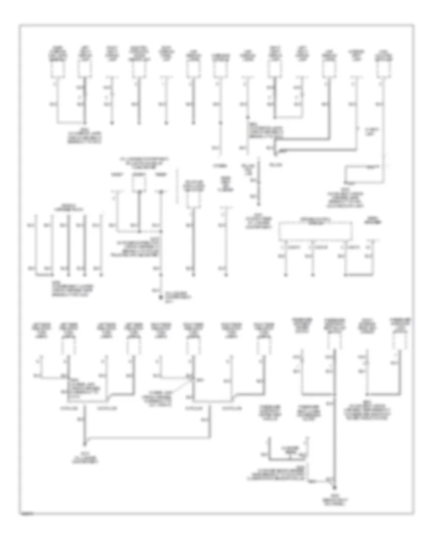
Ground Distribution Wiring Diagram (4 of 4) for Mercury Grand Marquis GS 2005
List of elements for Ground Distribution Wiring Diagram (4 of 4) for Mercury Grand Marquis GS 2005:
- (in luggage compartment) g411
- (in luggage compartment) police trunk relay/ fuse center
- C4231a
- C4231b
- C4231c
- Electro- chromatic inside mirror unit
- Ends in harness trunk
- G200 (behind right kick panel)
- G401 (at right rear of luggage compartment)
- G410 (in luggage compartment)
- High mounted stoplamp
- In rear lamp wiring harness, in breakout to c411 (right))
- Interior spot lamp
- Left rear park/stop turn lamp 2
- Left rear park/stop/ turn lamp 1
- Left vanity mirror lamp
- Map reading lamps
- Nca
- Others
- Overhead console
- Passenger seat lumbar compressor motor
- Passenger side door lock switch
- Passenger side front heated seat module
- Passenger side front seat adjust switch
- Passenger side seat heater switch
- Police
- Police/ taxi/ lwb
- R4.b1
- R4.b3
- R4.b4
- Rear deck led flasher
- Rear interior/ map lamps assembly
- Right exterior rear view mirror
- Right rear park/stop turn lamp 2
- Right rear park/stop/ turn lamp 1
- Right vanity mirror lamp
- Roof opening panel unit
- S320 (in power seats harness, near breakout to occupant classification sensor module)
- S400 (in rear lamp wiring harness, in breakout to c410)
- S401
- S402 (in main body wiring harness, near breakout to high mounted stop lamp)
- S465 (in emergency jumper wiring harness, near breakout for c422)
- S476 (in power distribution wiring harness, in breakout to police trunk relay/fuse center)
- S600 (in main body wiring harness, near breakout to passenger side front power window motor)
- S902 (in interior lamps wiring harness, in breakout to c913)
- Siren amplifier
- Strobe control module
- Trunk air circulation fan motor
- W/ heated seats
- W/ police
- W/ spot lamp
- W/o police
HEADLIGHTS
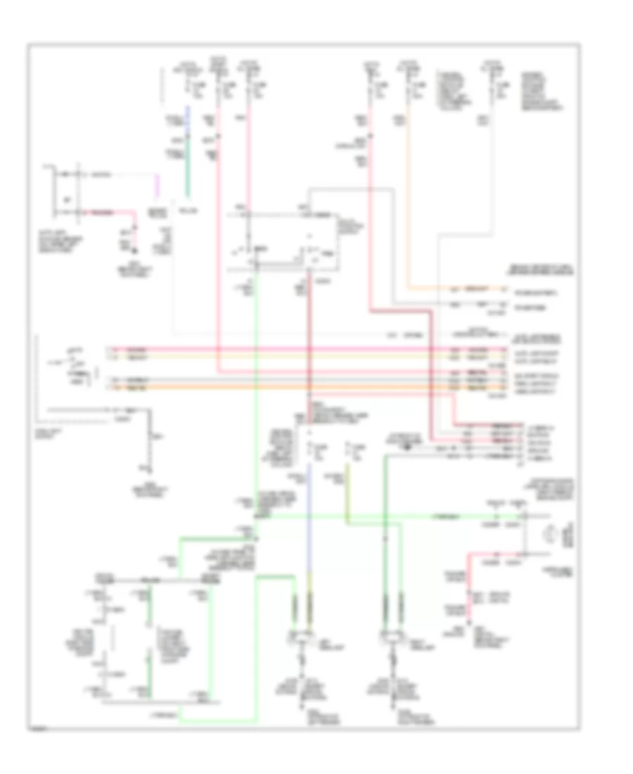
Headlamps Wiring Diagram, with DRL for Mercury Grand Marquis GS 2005
List of elements for Headlamps Wiring Diagram, with DRL for Mercury Grand Marquis GS 2005:
- (analog)
- (at front of right fender) g109
- (behind center of dash) lighting control module
- (digital)
- (or 964)
- Analog
- Auto
- Auto lamp delay
- Auto lamp enable (or ign run or acc)
- Auto lamp on/off
- Auto lamp/ sunload sensor (on upper left side of dash)
- Bat pwr
- Battery junction box (bjb) (in right front of engine compt, behind battery)
- Breakout to c260) s278
- C1365a
- C202c
- C205a
- C2145a
- C2145b
- C2145c
- C220a
- C220c
- C2220b
- Central junction box (cjb) (below dash, left of steering column)
- Crown police
- Daytime running lamps (drl) module (right rear of engine compt)
- Digital
- Except police
- Fuse 10a
- Fuse 15a
- Fuse 20a
- Fuse 7.5a
- G102 (at front of left fender)
- G109 (at front of right fender)
- G201 (behind right kick panel)
- G201 (digital) (behind right kick panel)
- G203 (analog)
- G203 (behind right kick panel)
- Ground
- Head
- Headlamp input
- Hi beam in
- Hi beam indicator
- Hot at all times
- Hot in acc or run
- Hot in run
- Hot in start or run
- Ign (run)
- Ign start or run
- Instrument cluster
- Left headlamp
- Lo beam in
- Main light switch
- Multi- function switch
- Nca
- Off
- Park
- Park lamp input
- Pass
- Pnk
- Police
- Power (battery)
- Power feed
- Right headlamp
- S114
- S114 (except crown victoria)
- S138 (in dash panel to headlamp junction harness, near breakout to pcm)
- S159 (crown victoria)
- S200 (in main body wiring harness, near breakout to c264)
- S201
- S202
- S207
- S209 (manual a/c)
- S210
- S276
- Wig-wag jumper 1 (on right front side of engine compt)
- Wig-wag module (right side of engine compt)
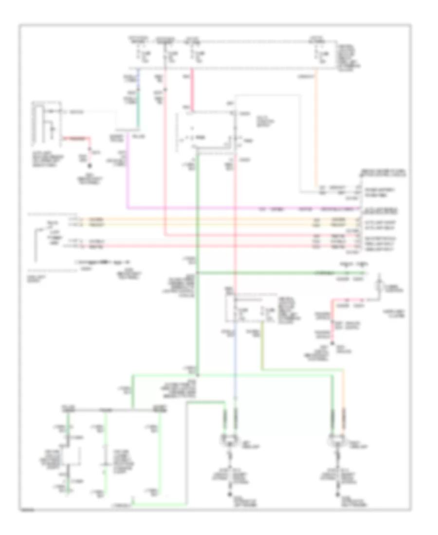
Headlamps Wiring Diagram, without DRL for Mercury Grand Marquis GS 2005
List of elements for Headlamps Wiring Diagram, without DRL for Mercury Grand Marquis GS 2005:
- (analog)
- (behind center of dash) lighting control module
- (digital)
- (or 964)
- (or ign run or acc)
- Analog
- Auto
- Auto lamp delay
- Auto lamp enable
- Auto lamp on/off
- Auto lamp/ sunload sensor (on upper left side of dash)
- C1365a
- C202c
- C205a
- C2145a
- C2145b
- C2145c
- C220a
- C220c
- C2220b
- Central junction box (cjb) (below dash, left of steering column)
- Digital
- Except police
- Fuse 10a
- Fuse 15a
- Fuse 20a
- Fuse 7.5a
- G102 (at front of left fender)
- G109 (at front of right fender)
- G201 (behind right kick panel)
- G201 (digital) (behind right kick panel)
- G203 (analog)
- G203 (behind right kick panel)
- Head
- Headlamp input
- Hi beam indicator
- Hot at all times
- Hot in run or acc
- Hot in run or start
- Ign start or run
- Instrument cluster
- Left headlamp
- Main light switch
- Multi- function switch
- Nca
- Off
- Park
- Park lamp input
- Pass
- Pnk
- Police
- Police crown
- Power (battery)
- Power feed
- Right headlamp
- S112 (except crown victoria)
- S114 (except crown victoria)
- S138 (in dash panel to headlamp junction harness, near breakout to pcm)
- S158 (crown victoria)
- S159 (crown victoria)
- S201
- S202
- S207
- S210
- S276
- S278 (in main wiring harness, near breakout to lighting control module)
- Wig-wag jumper 1 (on right front side of engine compt)
- Wig-wag module (right side of engine compt)
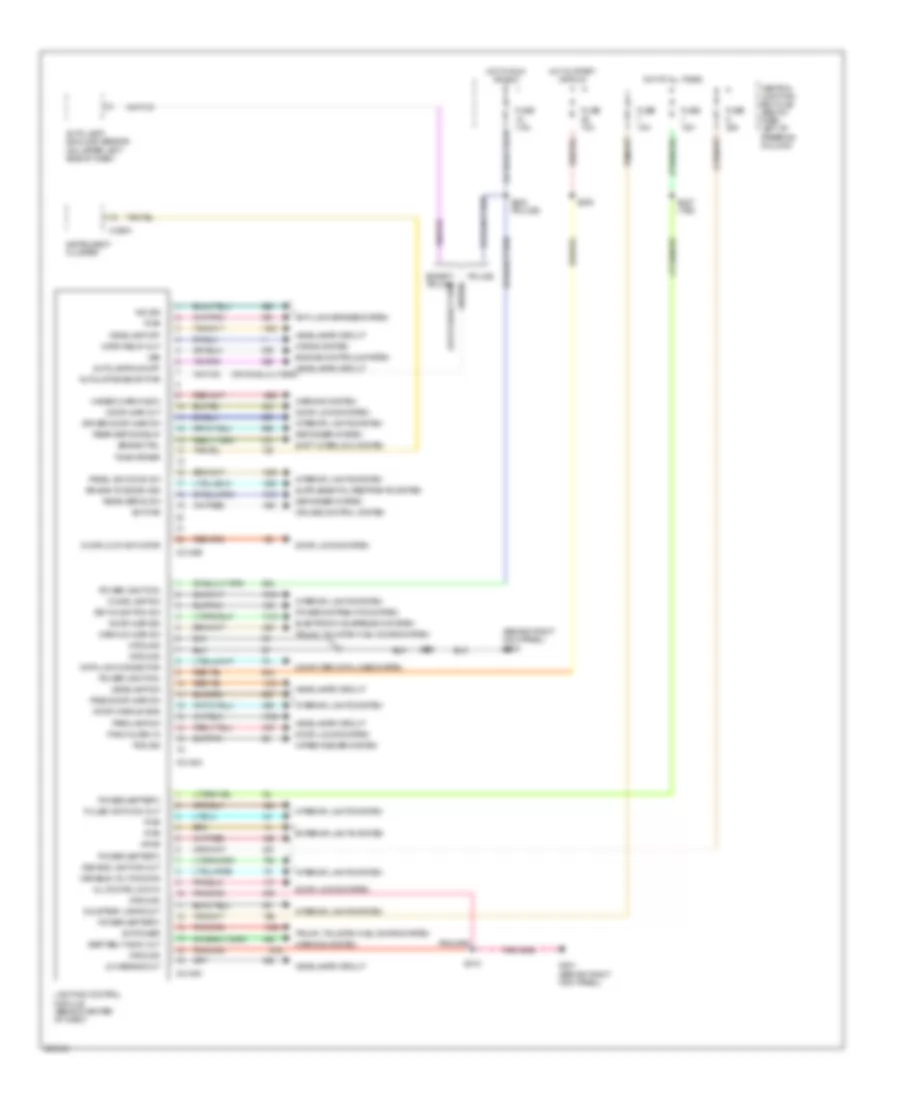
Lighting Control Module Wiring Diagram for Mercury Grand Marquis GS 2005
List of elements for Lighting Control Module Wiring Diagram for Mercury Grand Marquis GS 2005:
- (behind right kick panel) g203
- Air bag tone drv sig
- All doors lock in
- Anti-lock brakes system
- Auto lamp/ sunload sensor (on upper left side of dash)
- Autolamps on/off
- Autolmp enab or pwr
- Brake ctrl
- C2145a
- C2145b
- C2145c
- C220a
- Central junction box (cjb) (below dash, left of steering column)
- Computer data lines system
- Courtesy lamps out
- Cruise control system
- Data link connector
- Decklid ajar sw
- Defogger system
- Demand lighting out
- Dome lamp sw
- Door ajar out
- Door ajar sig
- Door handle sws
- Door lock actuator
- Door locks system
- Driver door ajar sw
- Electronic suspension system
- Engine controls system
- Exterior lights system
- Fuse 10a
- Fuse 15a
- Fuse 20a
- Fuse 7.5a
- G201 (behind right kick panel)
- Ground
- Hazard warn indic
- Headlamp off
- Headlamp sw
- Headlamps circuit
- Horn relay out
- Horns system
- Hot at all times
- Hot in run or acc
- Hot in start or run
- Ind sig
- Instrument cluster
- Interior lights system
- Key-in-ignition sw
- Lighting control module (behind center of dash)
- Low beams out
- Panel dim down sw
- Panic alarm in
- Parklamp sw
- Pass door ajar sw
- Police
- Pos sig
- Power (battery)
- Power (ignition)
- Power distribution system
- Pulse width dim out
- Pwr
- Rear defog relay
- Rear defog sw
- S201
- S202 (police)
- S210
- S227 (taxi)
- S276
- Seat belt indic out
- Shift interlock system
- Sw power
- Sw pwr
- Tone driver
- Trunk, tailgate, fuel doors system
- Variable volt dimming
- Vpwr
- Vss
- Warning system
- Wiper/washer system
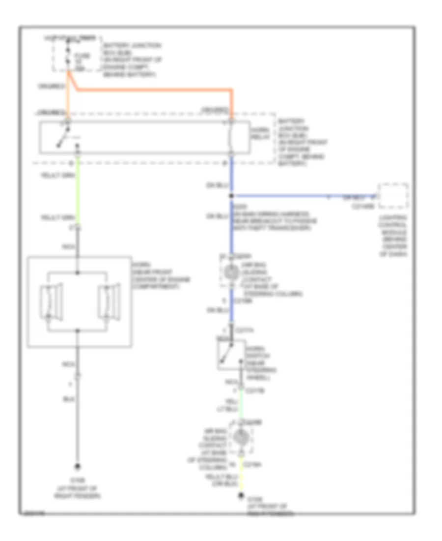
HORN
Horn Wiring Diagram for Mercury Grand Marquis GS 2005
List of elements for Horn Wiring Diagram for Mercury Grand Marquis GS 2005:
- (at front of right fender)
- Air bag sliding contact (at base of steering column)
- Battery junction box (bjb) (in right front of engine compt, behind battery)
- C2145b
- C217a
- C217b
- C218a
- C218b
- Fuse 20a
- G108
- G109 (at front of right fender)
- Horn (near front center of engine compartment)
- Horn relay
- Horn switch (near steering wheel)
- Hot at all times
- Lighting control module (behind center of dash)
- Nca
INSTRUMENT CLUSTER
Analog Cluster Wiring Diagram for Mercury Grand Marquis GS 2005
List of elements for Analog Cluster Wiring Diagram for Mercury Grand Marquis GS 2005:
- "air bag" indicator
- "traction control" ind
- (6 bulbs)
- (at front of left fender) g103
- (in main wiring harness, in breakout to instrument cluster) s202
- (taxi) s227
- Abs control module (at left front of engine compt)
- Abs indicator
- Air bag indicator
- Air suspension module (behind right side of dash, above glove box)
- Anti-slosh module
- Brake fluid level switch (on brake fluid reservoir)
- Brake ind ctrl
- C175b
- C175t
- C2131a
- C2145c
- C2220a
- C2220b
- C310a
- Cap indicator
- Central junction box (cjb) (below dash, left of steering column)
- Charge indicator
- Check fuel
- Check gauge indicator
- Check suspension/ fire suppression indicator
- Electronic throttle control ind
- Engine coolant temperature (ect) sensor (top right front of engine, near fuel injector 1)
- Engine coolant temperature gauge
- Exterior lights system
- Fuel gauge
- Fuel tank unit (in fuel tank)
- Fuse 10a
- Fuse 15a
- G102 (at front of left fender)
- G201 (behind right kick panel)
- G203 (behind right kick panel)
- G212 (at left kick panel)
- Gauge
- Gnd
- Headlights system
- Hi beam indicator
- Hot at all times
- Hot in run
- Hot in start or run
- Illumination lamps
- Indicator control
- Indicator output
- Instrument cluster
- Interior lights system
- Left turn indicator
- Lighting control module (behind center of dash)
- Low
- Low brake fluid level/ park brake ind
- Low fuel indicator
- Low oil pressure
- Malfunction indicator lamp (mil)
- Microprocessor
- Normal
- Oil pressure switch (lower left side of engine, above oil filter)
- Overdrive cancel ind
- Parking brake switch (behind left side of dash, on top of parking brake assembly)
- Powertrain control module (pcm) (left rear of engine compt)
- Restraints control module (below center of dash)
- Right turn indicator
- S104 (near breakout to g102)
- S112
- S207
- S210
- S247 (near breakout to c410)
- S267
- S276
- Safety belt indicator
- Speedometer
- Voltmeter
Electronic Cluster Wiring Diagram (1 of 2) for Mercury Grand Marquis GS 2005
List of elements for Electronic Cluster Wiring Diagram (1 of 2) for Mercury Grand Marquis GS 2005:
- (at front of left fender) g102
- (behind center of dash) electronic automatic temperature control (eatc) module
- (behind right side of dash, above glove box) air suspension module
- (in fuel tank) fuel tank unit
- (left rear of engine compt) powertrain control module (pcm)
- (on top right front of engine, near fuel injector 1) engine coolant temperature (ect) sensor
- Air susp ind
- C175b
- C175t
- C2131a
- C220a
- C220b
- C220c
- C228b
- Central junction box (cjb) (below dash, left of steering column)
- Charge ind
- Door ajar ind
- E/m
- Ect ind
- Eng/met
- Etcil
- Exterior lights system
- Fail-safe cooling ind
- Fuel cap ind
- Fuel level data
- Fuel level ind
- Fuse 10a
- Fuse 15a
- G201 (behind right kick panel)
- Gnd
- Headlights system
- Hi beam ind
- Hot at all times
- Hot in run
- Illum
- Illumination
- Ind
- Instrument cluster
- Interior lights system
- Left turn ind
- Low washer fluid ind
- Message center switch
- Microprocessor
- Mil ind
- Oil pres ind
- Oil pressure switch (lower left side of engine, above oil filter)
- Out
- Red
- Reset
- Right turn ind
- S112
- S202 (in main wiring harness, in breakout to instrument cluster)
- S210
- S227
- S247 (in main wiring harness, near breakout to c410)
- Safety belt indicator
- Select
- Speed control ind
- Speedometer
- Starting/charging system
- Taxi
- Tcil ind
- Tone driver
- Traction ctrl ind
- Trunk ajar ind
- Vbatt
- Vpwr
- Vref
- Washer fluid level switch (in washer fluid reservoir)
Electronic Cluster Wiring Diagram (2 of 2) for Mercury Grand Marquis GS 2005
List of elements for Electronic Cluster Wiring Diagram (2 of 2) for Mercury Grand Marquis GS 2005:
- (at front of left fender) g102
- (early production) s282
- (in dash panel to headlamp junction harness, near breakout to g102) s104
- Abs control module (at left front of engine compt)
- Abs ind
- Air bag ind
- Ajar lamp output
- Anti-lock brakes system
- Brake fluid level switch (on brake fluid reservoir)
- C2145a
- C2145b
- C2145c
- C2212a
- C2212b
- C501a
- C526a
- C602a
- C602b
- C715a
- C715b
- C820a
- Central junction box (cjb) (below dash, left of steering column)
- Decklid jar
- Door ajar indicator (taxi)
- Door ajar input
- Driver door module (bottom front of left front door)
- Driver side front door ajar switch (at top rear of left front door) c526b
- Driver side rear door ajar switch (at rear of left rear door)
- Driver's ajar switch
- Early production
- Fuse 10a
- G109 (at front of right fender)
- G203 (behind right kick panel)
- G212 (at left kick panel)
- G406 (at rear center of luggage compt)
- Hazard ind
- Hot in start or run
- Late production
- Lighting control module (behind center of dash)
- Low brake fluid level/ park brake ind
- Luggage compartment lid release solenoid (center rear of luggage compt lid)
- Parking brake switch (behind left side of dash, on top of parking brake assembly)
- Pass ajar switch
- Passenger side front door ajar switch (at top rear of right front door)
- Passenger side rear door ajar switch (at rear of right rear door) c820b
- S112
- S207
- S230 (in main body wiring harness, near breakout to temperature blend door actuator)
- S240 (in main wiring harness, in breakout to instrument cluster)
- S267
- S276
- S277 (near breakout to lighting control module)
- S403
- Safety belt ind out
- Seatbelt switch
- Tone request
- Trunk, tailgate, fuel doors system
- Warning lamps module (behind left side of dash)
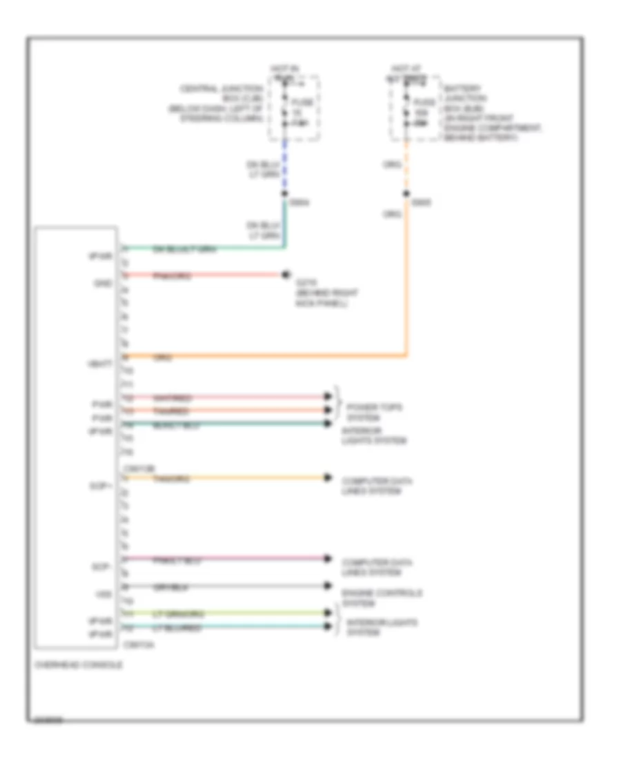
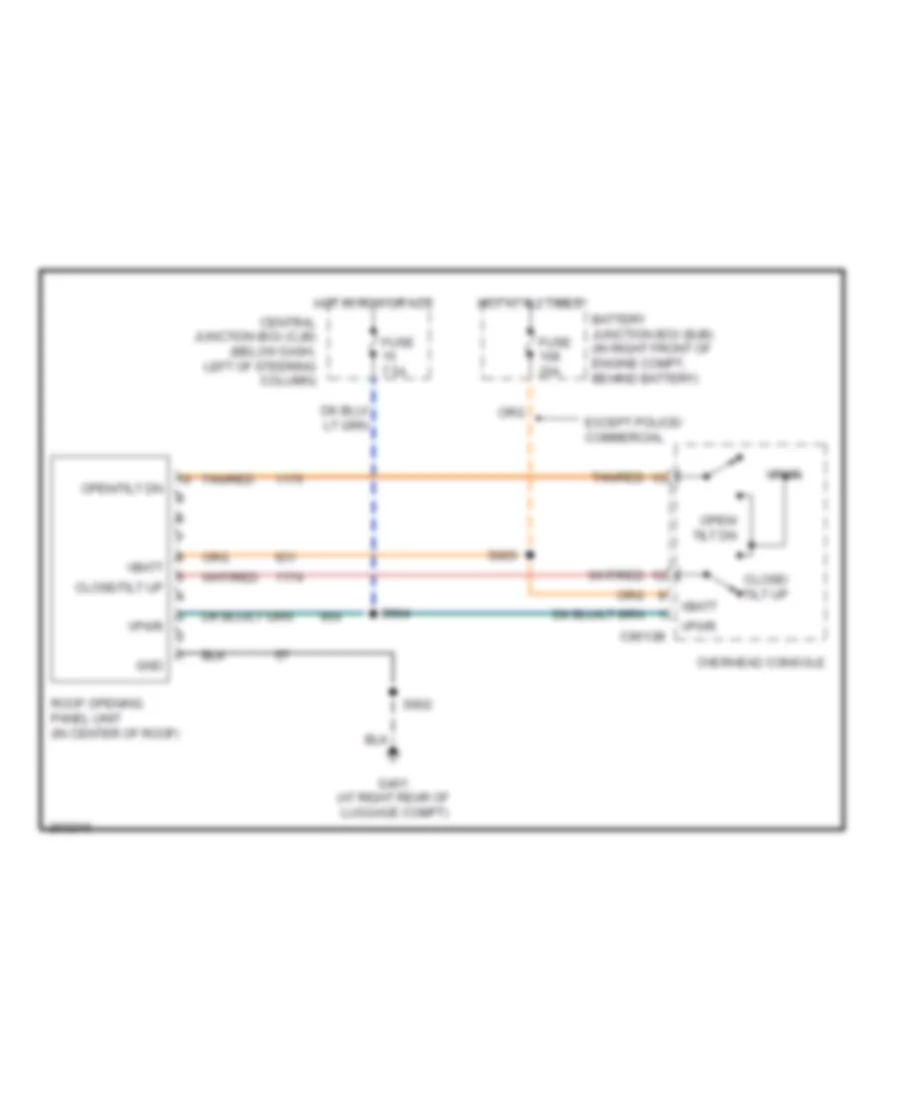
Overhead Console Wiring Diagram, with Roof Opening Panel for Mercury Grand Marquis GS 2005
List of elements for Overhead Console Wiring Diagram, with Roof Opening Panel for Mercury Grand Marquis GS 2005:
- Battery junction box (bjb) (in right front engine compartment, behind battery)
- C9013a
- C9013b
- Central junction box (cjb) (below dash, left of steering column)
- Computer data lines system
- Engine controls system
- Fuse 20a
- Fuse 7.5a
- G210 (behind right kick panel)
- Gnd
- Hot at all times
- Hot in run
- Interior lights system
- Overhead console
- Power tops system
- Pwr
- S904
- S905
- Scp+
- Scp-
- Tan/red
- Vbatt
- Vpwr
- Vss
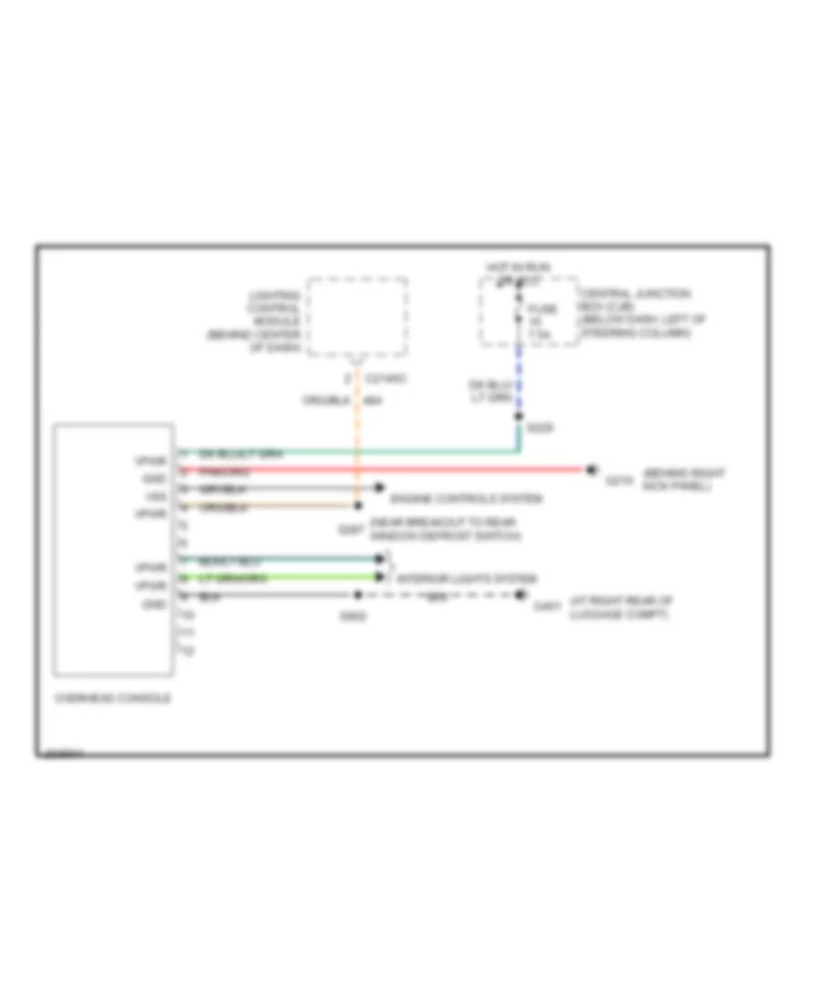
Overhead Console Wiring Diagram, without Roof Opening Panel for Mercury Grand Marquis GS 2005
List of elements for Overhead Console Wiring Diagram, without Roof Opening Panel for Mercury Grand Marquis GS 2005:
- (at right rear of luggage compt)
- (behind right kick panel)
- (near breakout to rear window defrost switch)
- C2145c
- Central junction box (cjb) (below dash, left of steering column)
- Engine controls system
- Fuse 7.5a
- G210
- G401
- Gnd
- Hot in run or acc
- Interior lights system
- Lighting control module (behind center of dash)
- Overhead console
- S229
- S287
- S902
- Vpwr
- Vss
INTERIOR LIGHTS
Courtesy Lamps Wiring Diagram for Mercury Grand Marquis GS 2005
List of elements for Courtesy Lamps Wiring Diagram for Mercury Grand Marquis GS 2005:
- (at rear center of luggage compartment) g406
- (at rear of left front door) left front exterior door handle switch
- (at rear of left rear door) driver side rear door ajar switch
- (at rear of right front door) right front exterior door handle switch
- (at rear of right rear door) passenger side rear door ajar switch
- (at right rear of luggage compartment) g401
- (at top rear of left front door) driver side front door ajar switch
- (at top rear of right front door) passenger side front door ajar switch
- (in interior lamps wiring harness, in breakout to c913)
- (in interior lamps wiring harness, near breakout to right vanity mirror lamp)
- (in main body wiring harness, near breakout to g200)
- (in main body wiring harness, near breakout to temperature blend door actuator) s223
- (in main wiring harness, in breakout to instrument cluster) s240
- (in main wiring harness, near breakout to eatc) s236
- (in main wiring harness, near breakout to passenger air bag deactivation indicator)
- Base vehicle/ police
- C205b
- C2145a
- C2145b
- C2145c
- C220b
- C2212a
- C526a
- C526b
- C9013a
- C9013b
- Central junction box (cjb) (below dash, left of steering column)
- Digital cluster
- Dimmer
- Door ajar
- Door ajar indicator
- Early production
- Emergency flasher relay block (in left rear of luggage compt)
- Except base vehicle/police
- Exterior lights system
- Fuse 15a
- G203 (behind right kick panel)
- G204 (behind right kick panel)
- Glove box lamp
- Handle sw
- Hot at all times
- Instrument cluster
- Interior
- Interior spot lamp (if equipped)
- Left footwell courtesy lamp
- Left vanity mirror lamp
- Lighting control module (behind center of dash)
- Luggage compartment lamp
- Luggage compartment lid release solenoid (on center rear of luggage compt lid)
- Main light switch
- Map reading lamps
- Nca
- Overhead console (w/ roof opening panel)
- Overhead console (w/o roof opening panel)
- Police
- Power distribution system
- Pwr
- Rear flasher relay
- Rear interior/ map lamps assembly
- Right footwell courtesy lamp
- Right vanity mirror lamp
- S204
- S222
- S227 (taxi)
- S238
- S259
- S290
- S402
- S403
- S900
- S902
- S903 (w/ roof opening panel)
- Trunk ajar
- Vbatt
- Vpwr
- Vref
- W/ roof opening panel
- W/o remote keyless entry
- W/o roof opening panel
Instrument Illumination Wiring Diagram for Mercury Grand Marquis GS 2005
List of elements for Instrument Illumination Wiring Diagram for Mercury Grand Marquis GS 2005:
- (at base of steering column) air bag sliding contact
- (behind right kick panel) g203
- (in main wiring harness, near breakout to eatc s233
- (in steering wheel control switch jumper harness) s293
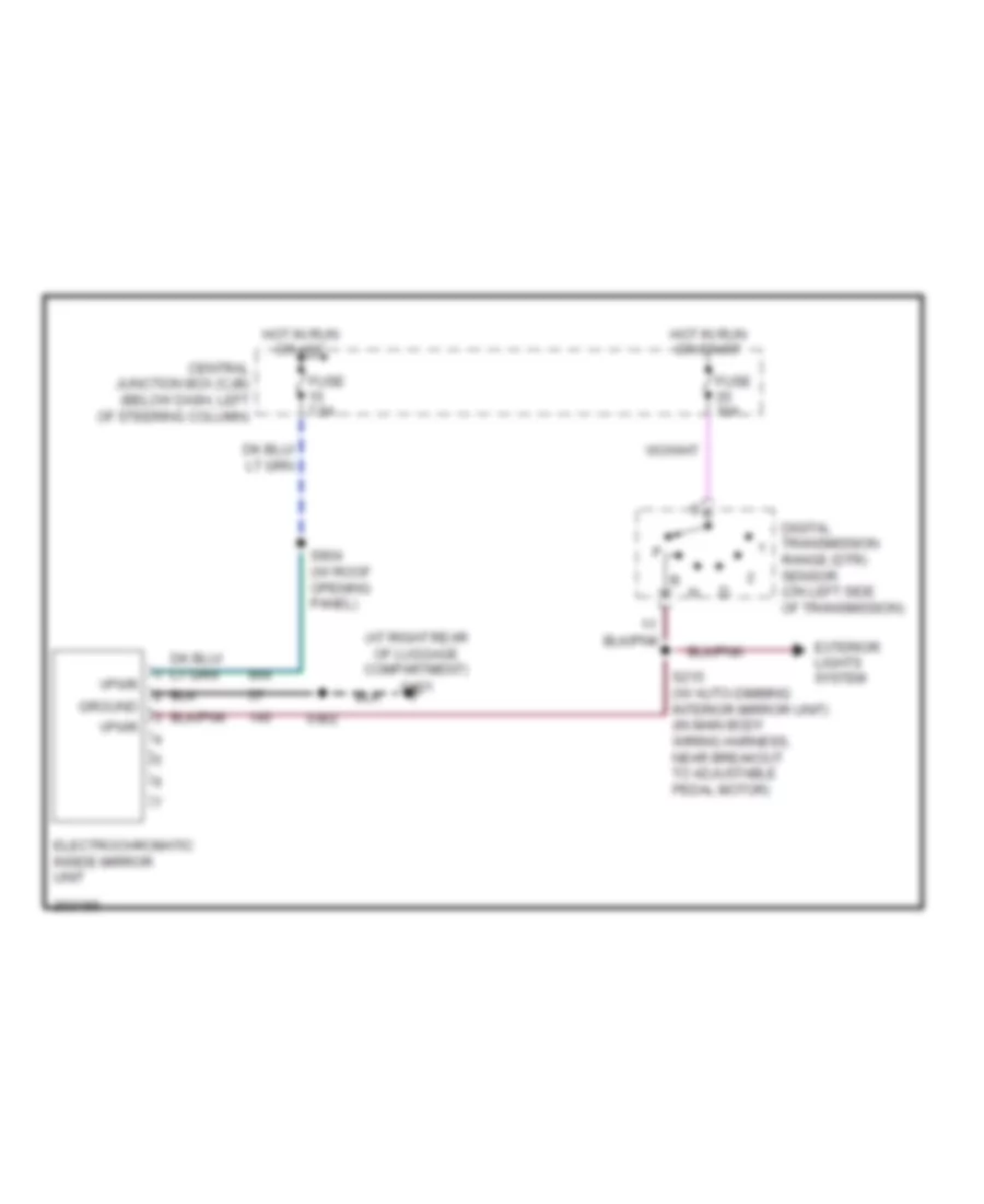
- Adjustable pedal switch
- Alpine, sanyo
- Audio/ climate control switch
- Auto
- Automatic a/c
- Base audio
- C205a
- C205b
- C2145a
- C2145b
- C2145c
- C218a
- C218b
- C220a
- C220c
- C2220b
- C228a
- C228b
- C2330a
- C2330b
- C240
- C290a
- C294d
- C501a
- C9013a
- Central junction box (cjb) (below dash, left of steering column)
- Dimmer
- Driver door module (bottom front of left front door)
- Driver side door lock switch
- Electronic automatic temperature control (eatc) module (behind center of dash)
- Except taxi
- Floor shifter
- Function selector switch assembly
- Fuse 10a
- Fuse 15a
- Fuse 5a
- Fuse 7.5a
- G200 (w/ power seat) (behind right kick panel)
- G201 (behind right kick panel)
- G203 (behind right kick panel)
- G204 (behind right kick panel)
- G209 (w/o power seat) (behind right kick panel)
- G212 (at left kick panel)
- Head
- Hot at all times
- Hot in run or acc
- Hot in start
- Illum
- Illumination
- Instrument cluster (analog)
- Instrument cluster (digital)
- Interior
- Key pad switch assembly
- Lighting control module (behind center of dash)
- Main light switch
- Manual a/c
- Message center switch (digital)
- Off
- On/off sig
- Overhead console
- Park
- Passenger side door lock switch
- Power distribution system
- Pwr
- Radio
- Rear window defrost switch
- S201
- S204
- S207
- S210
- S229
- S287 (in main wiring harness, near breakout to rear window defrost switch)
- S294
- S500
- S501
- S600
- Steering wheel/ speed control switch
- Traction control switch
- Vbatt
- Vref
- W/ steering wheel audio/climate control switch
- W/o steering wheel audio/climate control switch
POWER DISTRIBUTION
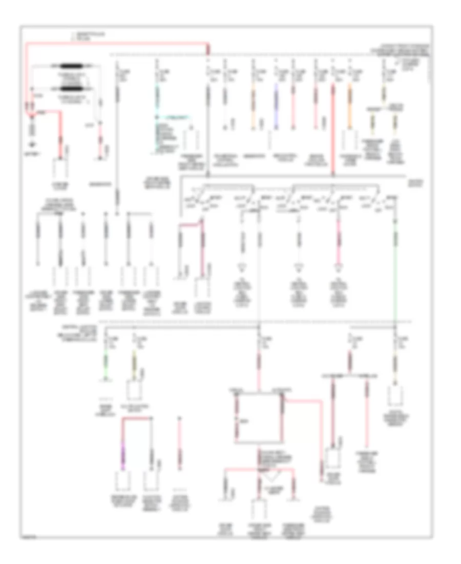
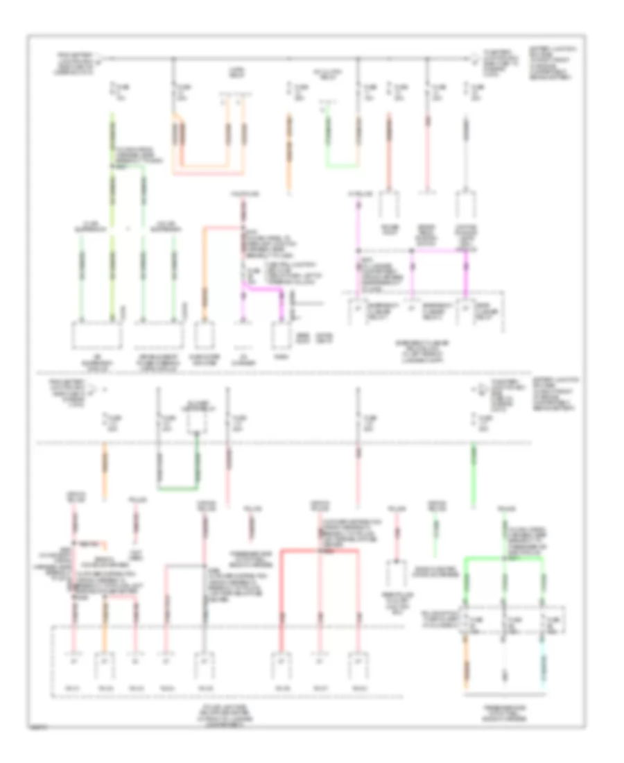
Power Distribution Wiring Diagram (1 of 5) for Mercury Grand Marquis GS 2005
List of elements for Power Distribution Wiring Diagram (1 of 5) for Mercury Grand Marquis GS 2005:
- (in main wiring harness, near breakout to c248) s242
- (in right front of engine compartment, behind battery) battery junction box (bjb)
- Abs control module
- Acc
- Automatic a/c
- Battery
- Brake shift interlock
- C102a
- C102b
- C1048a
- C175b
- C197a
- C202a
- C2145a
- C294a
- C501a
- C501b
- C501c
- Central junction box (cjb) (below dash, left of steering column)
- Crown police
- Daytime running lamps (drl) module
- Digital transmission range (dtr) sensor
- Driver door module
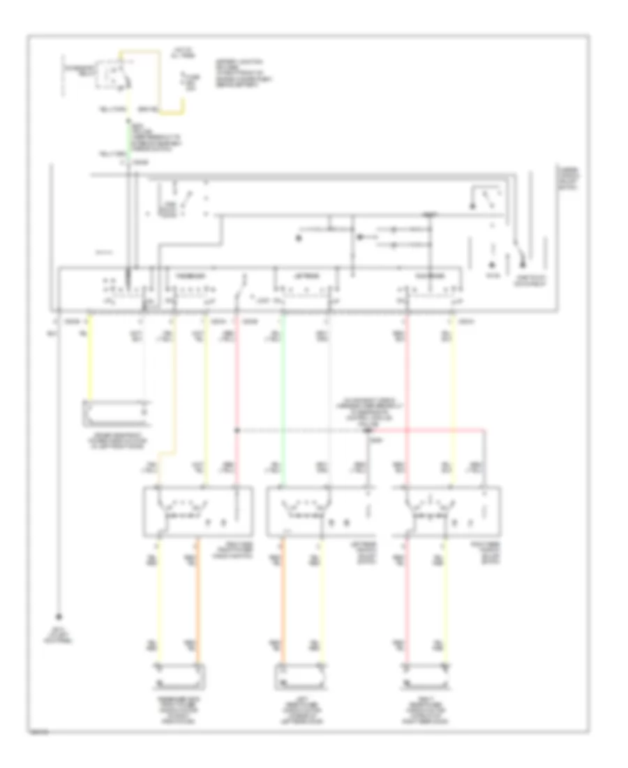
- Driver side front heated seat module
- Driver side front seat adjust switch
- Driver side lumbar adjust switch
- Engine cooling fan module
- Except police
- Function selector switch assembly
- Fuse 10a
- Fuse 15a
- Fuse 20a
- Fuse 25a
- Fuse 30a
- Fuse 40a
- Fuse 50a
- Fuse 5a
- Fusible link b
- Generator
- Ignition switch
- Lighting control module
- Lock
- Low band radio ends in trunk harness
- Luggage compart- ment lid release switch 2
- Luggage compartment lid release switch 1
- Manual a/c
- Multifunction switch
- Nca
- Off
- Passenger side front heated seat module
- Passenger side front seat adjust switch
- Passenger side in footwell ends in harness
- Passenger side lumbar adjust switch
- Police
- Powertrain control module (pcm)
- Red
- Run
- S137
- S162
- S209
- Start
- Starter motor
- Temperature blend door actuator
- To central junction box fuse 15 (diagram 5 of 5)
- To central junction box fuse 2 (diagram 2 of 5)
- To central junction box fuse 20 (diagram 2 of 5)
- To fuse 8 (diagram 2 of 5)
- To g200)
- W/ heated seats
- W/ police
- W/o police
- Windshield wiper motor
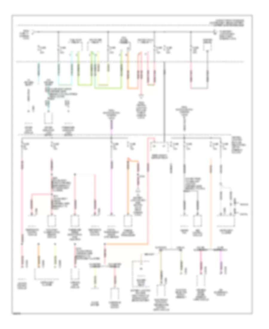
Power Distribution Wiring Diagram (2 of 5) for Mercury Grand Marquis GS 2005
List of elements for Power Distribution Wiring Diagram (2 of 5) for Mercury Grand Marquis GS 2005:
- (in dash panel to headlamp junction harness, near breakout to pcm) s101
- (in right front of engine compartment, behind battery) battery junction box (bjb)
- Abs control module
- Air suspension module
- Analog
- Automatic a/c
- Battery junction box (bjb) (right front of engine compt, behind battery)
- Blower motor relay
- C2131b
- C2145a
- C220a
- C220c
- C2220a
- C2220b
- C2231b
- C228a
- C294a
- C310a
- C310b
- C501c
- Central junction box (cjb) (below dash, left of steering column)
- Digital
- Digital transmission range (dtr) sensor
- Driver door module
- Driver side door lock switch
- Electronic automatic temperature control (eatc) module
- Floor shifter
- From central junction box (cjb) fuse 24 (diagram 2 of 5)
- From fuse 111 (diagram 1 of 5)
- From ignition switch (diagram 1 of 5)
- Fuel pump relay
- Function selector switch assembly
- Fuse 10a
- Fuse 15a
- Fuse 20a
- Fuse 30a
- Fuse 40a
- Heated pvc
- Ignition coils relay
- Instrument cluster
- Lighting control module
- Manual a/c
- Occupant classification sensor module
- Overdrive cancel switch
- Passenger airbag deactivation (pad) indicator
- Passenger side door lock switch
- Passive anti-theft transceiver
- Pcm power diode
- Pcm power relay
- Rear window defrost relay
- Restraints control module
- S164
- S208 (in main body wiring harness, near breakout to instrument cluster)
- S213 (in main body wiring harness, near breakout to c237)
- S276 (in main wiring harness, near breakout to instrument cluster)
- Starter relay
- To battery junction box (bjb) fuse 5 (diagram 3 of 5)
- To battery junction box (bjb) ignition coils relay (diagram 2 of 5)
- Variable assist power steering (vaps) module
- W/ air suspension
- W/ center console
- W/ keyless entry
- W/o air suspension
- W/o center console
- W/o keyless entry
- Warning lamps module
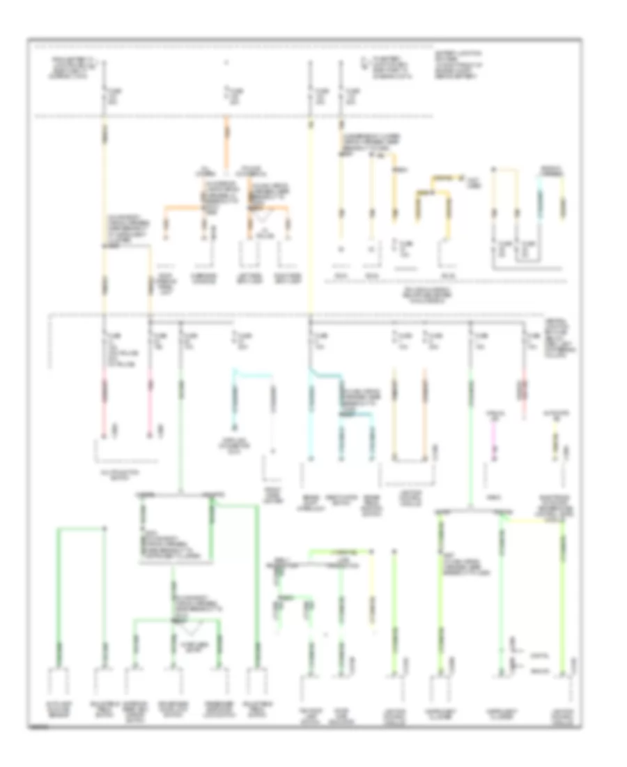
Power Distribution Wiring Diagram (3 of 5) for Mercury Grand Marquis GS 2005
List of elements for Power Distribution Wiring Diagram (3 of 5) for Mercury Grand Marquis GS 2005:
- (diagram 3 of 5)
- (in main wiring harness, near breakout to g200) s221
- (in main wiring harness, near breakout to passenger air bag module) s211
- (in power distribution wiring harness, in breakout to police light bar relay/fuse red center) s462
- (not used)
- 2131b
- A/c clutch relay
- Air suspension module
- Alpine, sanyo
- Base audio
- Battery junction box (bjb) (in right front of engine compartment, behind battery)
- Blower motor relay
- Brake pedal position switch
- C2231b
- C240
- C290a
- Cd changer
- Central junction box (cjb) (below dash, left of steering column)
- Compartment wiring harness, near breakout to c405)
- Crown police
- Daytime running lamps (drl) module
- Emergency flasher relay 1
- Emergency flasher relay 2
- Emergency flasher relay block (in left rear of luggage compt)
- Ends in console harness
- Ends in center console harness
- From battery junction box (bjb) fuse 16 c
- From battery junction box b (bjb) fuse 105 (diagram 2 of 5)
- Fuse 10a
- Fuse 15a
- Fuse 20a
- Fuse 25a
- Fuse 40a
- Fuse 50a
- Fuse b1 15a
- Fuse b2 15a
- Fuse b3 15a
- Horn relay
- Passenger side in footwell ends in harness
- Police
- Police light bar relay/fuse center (in front of luggage compartment)
- Police option fuse holder (in glove box)
- Power point
- R4.c1
- R4.c2
- R4.c3
- R4.c4
- R4.c5
- R4.c6
- R4.c7
- R4.c8
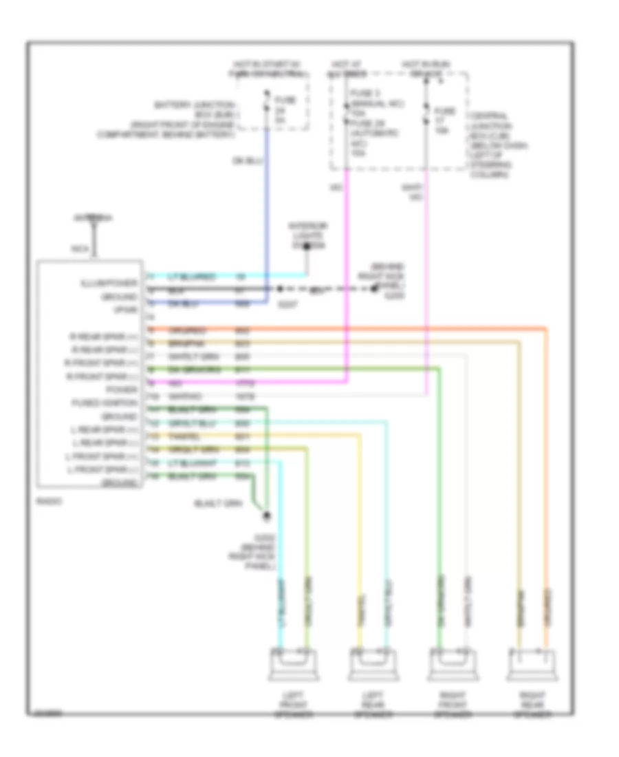
- Radio
- Rear flasher relay
- Rear police auxiliary junction box
- Red
- S466
- S469 (in power distribution wiring harness, in breakout to police light bar relay/fuse center)
- Subwoofer amplifier
- To battery junction box (bjb) fuse 103 (diagram 4 of 5)
- To battery junction box (bjb) fuse 113 (diagram 3 of 5)
- To g212)
- Variable assist power steering (vaps) module
- W/ air suspension
- W/ police
- W/o air suspension
- W/o police
Power Distribution Wiring Diagram (4 of 5) for Mercury Grand Marquis GS 2005
List of elements for Power Distribution Wiring Diagram (4 of 5) for Mercury Grand Marquis GS 2005:
- (in emergency jumper wiring harness, near breakout to c298) s291
- (in interior lamps wiring harness, in breakout to c913) s905
- (in main body wiring harness, near breakout to g212) s254
- (in main body wiring harness, near breakout to instrument cluster) s206
- (in main wiring harness, near breakout to c248) s237
- (not used)
- 9013b
- Adjustable pedal switch
- All others
- Analog
- Autolamp/ sunload sensor
- Automatic a/c
- Battery junction box (bjb) (in right front of engine compt, behind battery)
- Brake pedal position switch
- Brake shift interlock
- C202a
- C202c
- C2145c
- C220a
- C2212b
- C2220a
- C228a
- Central junction box (cjb) (below dash, left of steering column)
- Data link connector (dlc)
- Deactivator switch
- Digital
- Door ajar indicator
- Driver side door lock switch
- Electronic automatic temperature control (eatc) module
- Ends in harness
- Exterior rear view mirror switch
- From battery junction box d (bjb) fuse 117 (diagram 3 of 5)
- Front cigar lighter
- Fuse 10a
- Fuse 15a
- Fuse 15a (w/o police) 20a (w/ police)
- Fuse 20a
- Fuse 40a
- Fuse 50a
- Fuse a1 10a
- Fuse a2 5a
- Fuse a3 5a
- Instrument cluster
- Late production
- Left side spot lamp
- Lighting control module
- Manual a/c
- Multifunction switch
- Overhead console
- Passenger side door lock switch
- Pnk
- Police glove box relay/fuse center (in glove box)
- Police/ commercial
- R2.a1
- R2.a2
- R2.a4
- Radio
- Right side spot lamp
- Roof opening panel unit
- S227 (in main wiring harness, near breakout to c260)
- S282
- S284
- S286
- Tan
- Taxi roof lamp switch
- To battery junction box (bjb) fuse 118 (diagram 5 of 5)
- W/ keyless entry
- W/ pats
- W/ police
- W/ taxi
- W/o pats
- W/o taxi
Power Distribution Wiring Diagram (5 of 5) for Mercury Grand Marquis GS 2005
List of elements for Power Distribution Wiring Diagram (5 of 5) for Mercury Grand Marquis GS 2005:
- (in dash panel to headlamp junction harness, near breakout to battery junction box) s121
- (in emergency jumper wiring harness, near breakout for c422) s470
- (in main body wiring harness, near breakout to exterior rearview mirror switch) (w/ police) s502
- (in main wiring harness, in breakout to instrument cluster) s202
- (in power distribution wiring harness, at breakout for police luggage compartment
- Accessory relay
- Air suspension compressor relay
- Alpine, sanyo
- Base audio
- Battery junction box (bjb) (in right front of engine compartment, behind battery)
- C2145a
- C2145b
- C240
- C290a
- C504b
- C9013b
- Central junction box (cjb) (below dash, left of steering column)
- Crown police
- Driver side door lock switch
- Driver side seat heater switch
- Electro- chromatic inside mirror unit
- From battery junction box e (bjb) fuse 116 (diagram 4 of 5)
- From ignition switch (diagram 1 of 5)
- Fuse 10a
- Fuse 20a
- Fuse 30a (w/o police) 40a (w/ police)
- Fuse 50a
- Fuse 7.5a
- Fuse b1 5a
- Fuse b2 10a
- Fuse b3 5a
- Fuse b7 20a
- G109 (at front of right fender)
- Harness, near breakout to c248) s229
- Lighting control module
- Luggage compartment lid release switch 1
- Luggage compartment lid release switch 2
- Master window adjust switch
- Nca
- Overhead console
- Passenger side door lock switch
- Passenger side seat heater switch
- Police
- Police power relay
- Police trunk relay/fuse center (in luggage compartment)
- Police trunk relay/fuse center (in luggage compt)
- R4.b1
- R4.b2
- R4.b3
- R4.b4
- R4.b5
- Radio
- Rear police auxiliary junction box
- Relay/fuse center)
- Roof opening panel unit
- S474
- S478
- S904 (near breakout to electrochromatic inside mirror unit)
- To headlamp junction harness, near breakout to battery junction box) s120
- Trunk ends in harness
- W/ police
- W/ roof opening panel
- W/o police
- W/o roof opening panel
- Windshield wiper motor
POWER DOOR LOCKS
Power Door Locks Wiring Diagram, with Keyless Entry for Mercury Grand Marquis GS 2005
List of elements for Power Door Locks Wiring Diagram, with Keyless Entry for Mercury Grand Marquis GS 2005:
- (behind right kick panel) g201
- (in main body wiring harness, in breakout to driver's door module)
- (in main body wiring harness, near breakout to c248) s229
- (in main body wiring harness, near breakout to g212)
- (in main wiring harness, near breakout to lighting control module)
- (near breakout to driver's door module) s506
- 1/2
- 3/4
- 5/6
- 7/8
- 9/0
- Battery junction box (bjb) (in right front of engine compt, behind battery)
- C2145b
- C2145c
- C220a
- C501a
- C501b
- C501c
- Central junction box (cjb) (below dash, left of steering column)
- Computer data lines system
- Data link connector (dlc) (behind left side of dash)
- Digital
- Door ajar
- Door ajar ind
- Door lock
- Driver door module (bottom front of left front door)
- Driver side door lock switch
- Fuse 10a
- Fuse 20a
- Fuse 5a
- Fuse 7.5a
- G200 (w/ power seat) (behind right kick panel)
- G209 (w/o power seat) (behind right kick panel)
- G212 (at left kick panel)
- G406 (at rear center of luggage compt)
- Gnd
- Hndl sw sig rtn c2145a
- Hot at all times
- Hot in run
- Hot in run or acc
- Hot in start
- Illum
- Illumination
- Instrument cluster
- Iso
- Key pad illum
- Key pad sw a
- Key pad sw b
- Key pad sw c
- Key pad switch assembly
- Left front door lock actuator (at rear of left front door)
- Left rear door lock actuator (at rear of left rear door)
- Lighting control module (behind center of dash)
- Lock
- Luggage compartment lid release solenoid (on center rear of luggage compt lid)
- Luggage compt lid release switch 1
- Passenger side door lock actuator (at rear of right front door)
- Passenger side door lock switch
- Pwr
- Right rear door lock actuator (at rear of right rear door)
- S217
- S254
- S260 (in main body wiring harness, near breakout to g212)
- S261 (near breakout to g212)
- S262
- S263
- S271 (in main wiring harness, in breakout to data link connector)
- S277
- S403
- S500
- S503
- S510 (near breakout to exterior rearview mirror switch)
- S600
- Sig rtn
- Trunk lid
- Unlock
- Vbatt
- Vpwr
- Vref dr handle
- Vref out
Power Door Locks Wiring Diagram, without Keyless Entry for Mercury Grand Marquis GS 2005
List of elements for Power Door Locks Wiring Diagram, without Keyless Entry for Mercury Grand Marquis GS 2005:
- (in main body wiring harness, near breakout to passenger side front power window motor)
- Battery junction box (bjb) (in right front of engine compt, behind battery)
- Central junction box (cjb) (below dash, left of steering column)
- Driver side door lock switch
- Fuse 20a
- Fuse 7.5a
- G200 (w/ power seat) (behind right kick panel)
- G209 (w/o power seat) (behind right kick panel)
- G212 (at left kick panel)
- Hot at all times
- Hot in run or acc
- Illumination
- Left front door lock actuator (at rear of left front door)
- Left rear door lock actuator (at rear of left rear door)
- Lock
- Passenger side door lock actuator (at rear of right front door)
- Passenger side door lock switch
- Right rear door lock actuator (at rear of right rear door)
- S229
- S232
- S501
- S600
- S601
- Unlock
POWER MIRRORS
Electronic Day/Night Mirror Wiring Diagram for Mercury Grand Marquis GS 2005
List of elements for Electronic Day/Night Mirror Wiring Diagram for Mercury Grand Marquis GS 2005:
- (at right rear of luggage compartment) g401
- Central junction box (cjb) (below dash, left of steering column)
- Digital transmission range (dtr) sensor (on left side of transmission)
- Electrochromatic inside mirror unit
- Exterior lights system
- Fuse 10a
- Fuse 7.5a
- Ground
- Hot in run or acc
- Hot in run or start
- S215 (w/ auto-dimming interior mirror unit) (in main body wiring harness, near breakout to adjustable pedal motor)
- S902
- S904 (w/ roof opening panel)
- Vpwr
Power Mirrors Wiring Diagram for Mercury Grand Marquis GS 2005
List of elements for Power Mirrors Wiring Diagram for Mercury Grand Marquis GS 2005:
- (w/o keyless entry) s501
- Central junction box (cjb) (below dash, left of steering column)
- Defogger system
- Down
- Exterior rear view mirror switch
- Fuse 10a
- G212 (at left kick panel)
- Hot at all times
- Left
- Left exterior rear view mirror
- Left mirror select
- Left/ right
- Left/ right m
- Nca
- Right
- Right exterior rear view mirror
- Right mirror select
- S254 (w/ keyless entry)
- S500 (w/ keyless entry)
- S503 (in main body wiring harness, in breakout to driver's door module)
- Up/ down m
POWER SEATS
Adjustable Pedal Wiring Diagram for Mercury Grand Marquis GS 2005
List of elements for Adjustable Pedal Wiring Diagram for Mercury Grand Marquis GS 2005:
- Adjustable pedal motor (below left side of dash)
- Adjustable pedal switch
- Central junction box (cjb) (below dash, left of steering column)
- Fuse 10a
- Fwd
- G203 (behind right kick panel)
- G204 (behind right kick panel)
- Hot at all times
- Interior lights system
- Red
- Rwd
- S203 (w/ pats)
- S204
- S207
Driver Power Seat Wiring Diagram for Mercury Grand Marquis GS 2005
List of elements for Driver Power Seat Wiring Diagram for Mercury Grand Marquis GS 2005:
- (at left kick panel) g213
- Backrest of seat
- Battery junction box (bjb) (in right front of engine compt, behind battery)
- Circuit breaker 20a
- Driver seat recliner motor (in driver's seat)
- Driver side front seat adjust switch
- Entire seat
- Front of seat
- Fwd
- Hot at all times
- Left power seat motor assembly (under left front seat)
- Nca
- Rear of seat
- Rwd
- S242
Heated Seats Wiring Diagram for Mercury Grand Marquis GS 2005
List of elements for Heated Seats Wiring Diagram for Mercury Grand Marquis GS 2005:
- (at left kick panel) g212
- (behind right kick panel) g200
- (w/ keyless entry) s500
- Battery junction box (bjb) (in right front of engine compt, behind battery)
- Central junction box (cjb) (below dash, left of steering column)
- Driver side front heated seat module (under driver seat)
- Driver side seat heater switch
- Fuse 10a
- Fuse 20a
- Fuse 7.5a
- G200 (behind right kick panel)
- G212 (at left kick panel)
- High ind
- Hot at all times
- Hot in run
- Hot in run or acc
- Left front seat cushion heater (under left front seat)
- Low
- Low ind
- Nca
- Panel illum
- Passenger side front heated seat module (under passenger seat)
- Passenger side seat heater switch
- Red
- Right front seat cushion heater (under right front seat)
- S220
- S229
- S262
- S315
- S320
- S600
Lumbar Wiring Diagram for Mercury Grand Marquis GS 2005
List of elements for Lumbar Wiring Diagram for Mercury Grand Marquis GS 2005:
- Battery junction box (bjb) (in right front of engine compt, behind battery)
- Circuit breaker 20a
- Driver seat lumbar compressor motor (under driver's seat)
- G200 (behind right kick panel)
- G212 (at left kick panel)
- Hot at all times
- Left front lumbar adjust switch
- Out
- Passenger seat lumbar compressor motor (under passenger's seat)
- Pnk
- Right front lumbar adjust switch
- S242
- S300 (in power seats harness, under driver seat)
- S310 (in power seats harness, near breakout to right front lumbar compressor motor) pnk
- S315 (w/ heated seats)
- S320 (w/ heated seats)
Passenger Power Seat Wiring Diagram for Mercury Grand Marquis GS 2005
List of elements for Passenger Power Seat Wiring Diagram for Mercury Grand Marquis GS 2005:
- (behind right kick panel) g200
- Backrest of seat
- Battery junction box (bjb) (in right front of engine compt, behind battery)
- Circuit breaker 20a
- Entire seat
- Front of seat
- Fwd
- Hot at all times
- Nca
- Passenger seat recliner motor (under passenger's seat)
- Passenger side front seat adjust switch
- Rear of seat
- Right power seat motor assembly (under right front seat)
- Rwd
- S242
- S600
POWER TOP/SUNROOF
Power Top/Sunroof Wiring Diagram for Mercury Grand Marquis GS 2005
List of elements for Power Top/Sunroof Wiring Diagram for Mercury Grand Marquis GS 2005:
- Battery junction box (bjb) (in right front of engine compt, behind battery)
- C9013b
- Central junction box (cjb) (below dash, left of steering column)
- Close/ tilt up
- Close/tilt up
- Except police/ commercial
- Fuse 20a
- Fuse 7.5a
- G401 (at right rear of luggage compt)
- Gnd
- Hot at all times
- Hot in run or acc
- Open/ tilt dn
- Open/tilt dn
- Overhead console
- Roof opening panel unit (in center of roof)
- S902
- S904
- S905
- Tan/red
- Vbatt
- Vpwr
POWER WINDOWS
Power Windows Wiring Diagram for Mercury Grand Marquis GS 2005
List of elements for Power Windows Wiring Diagram for Mercury Grand Marquis GS 2005:
- (in main body wiring harness, near breakout to restraints control module)
- (police) s303
- Accessory relay
- Battery junction box (bjb) (in right front of engine compartment, behind battery)
- C504a
- C504b
- Driver
- Driver side front power window motor (in left front door)
- Fuse 20a
- G213 (at left kick panel)
- Hot at all times
- Left rear
- Left rear power window motor (in rear of left rear door)
- Left rear window adjust switch
- Lock
- Master window adjust switch
- One- touch down
- One-touch down relay
- Passenger
- Passenger side front power window motor (in right front door)
- Right rear
- Right rear power window motor (in front of right rear door)
- Right rear window adjust switch
- Right side front power window switch
- S264
- S502 (police) (near breakout to exterior rearview mirror switch)
- Vbatt
RADIO
Base Radio Wiring Diagram for Mercury Grand Marquis GS 2005
List of elements for Base Radio Wiring Diagram for Mercury Grand Marquis GS 2005:
- (behind right kick panel) g203
- Antenna
- Battery junction box (bjb) (right front of engine compartment, behind battery)
- Central junction box (cjb) (below dash, left of steering column)
- Fuse 10a
- Fuse 3 (manual a/c) 10a fuse 29 (automatic a/c) 15a
- Fuse 5a
- Fused ignition
- G202 (behind right kick panel)
- Ground
- Hot at all times
- Hot in run or acc
- Hot in start w/ park or neutral
- Illum power
- Interior lights system
- L front spkr (+)
- L front spkr (-)
- L rear spkr (+)
- L rear spkr (-)
- Left front speaker
- Left rear speaker
- Nca
- Power
- R front spkr (+)
- R front spkr (-)
- R rear spkr (+)
- R rear spkr (-)
- Radio
- Right front speaker
- Right rear speaker
- S207
- Vpwr
Premium Sound Radio Wiring Diagram for Mercury Grand Marquis GS 2005
List of elements for Premium Sound Radio Wiring Diagram for Mercury Grand Marquis GS 2005:
- (behind left rear seat) g407
- Air bag sliding contact (at base of steering column)
- Audio protocol a
- Audio protocol b
- Audio shield
- Audio system on
- Audio/climate control switch
- Battery junction box (bjb) (in right front of engine compartment, behind battery)
- C218a
- C218b
- C228b
- C290a
- C290b
- C290c
- Cd changer (alpine)
- Cd changer +
- Cd changer -
- Central junction box (cjb) (below dash, left of steering column)
- Electronic automatic temperature control (eatc) module (behind center of dash)
- Engine controls system
- Fan down
- Fan up
- Fuse 10a
- Fuse 15a
- Fuse 25a
- Fuse 5a
- G202 (behind right kick panel)
- G203 (behind right kick panel)
- G407 (behind left rear seat)
- Ground
- Hot at all times
- Hot in run or acc
- Hot in start w/ park or neutral
- Inst illum feed
- Interior lights system
- L cd changer +
- L cd changer -
- L front spkr +
- L front spkr -
- L rear spkr +
- L rear spkr -
- Left cd changer-
- Left front speaker
- Left rear speaker
- Mode
- Mute
- Nca
- Overload protected
- Phone
- Protocol a
- Protocol b
- R cd changer +
- R front spkr +
- R front spkr -
- R rear spkr +
- R rear spkr -
- Radio
- Rest
- Right cd changer-
- Right front speaker
- Right rear speaker
- Run/acc
- Rx sig
- S100
- S201
- S207
- S294 (in steering wheel control switch jumper harness)
- Shield
- Steering wheel sig
- Subwoofer amplifier (in luggage compartment, under rear package tray)
- Subwoofer mute
- Tan
- Temp down
- Temp up
- Tx sig
- Vbatt
- Vehicle speed sig
- Vpwr
SHIFT INTERLOCK
Shift Interlock Wiring Diagram, with Console for Mercury Grand Marquis GS 2005
List of elements for Shift Interlock Wiring Diagram, with Console for Mercury Grand Marquis GS 2005:
- (at left kick panel) g212
- (behind right kick panel) g204
- (in main body wiring harness, near breakout to variable assist power steering module)
- Brake pedal position switch (top of brake pedal support)
- Brake shift interlock (on steering column)
- Central junction box (cjb) (below dash, left of steering column)
- Fuse 10a
- Hot at all times
- Hot in run
- S204
- S225
- S237
- S267
- Solid state
Shift Interlock Wiring Diagram, without Console for Mercury Grand Marquis GS 2005
List of elements for Shift Interlock Wiring Diagram, without Console for Mercury Grand Marquis GS 2005:
- (at left kick panel) g212
- (in main body wiring harness, near breakout to variable assist power steering module)
- Bpp sw
- Brake pedal position switch (top of brake pedal support)
- Brake shift interlock (on steering column)
- Bsi
- C2145a
- C2145b
- Central junction box (cjb) (below dash, left of steering column)
- Fuse 10a
- Hot at all times
- Hot in start or run
- Lighting control module (behind center of dash)
- S225
- S237
- S267
- S276
- Vpwr
STARTING/CHARGING
Charging Wiring Diagram for Mercury Grand Marquis GS 2005
List of elements for Charging Wiring Diagram for Mercury Grand Marquis GS 2005:
- Analog
- Battery
- Battery junction box (bjb) (in right front of engine compt, behind battery)
- C175t
- C220a
- C220c
- C2220a
- Central junction box (cjb) (below dash, left of steering column)
- Charge ind
- Digital
- Fuse 10a
- Fuse 15a
- G100 (at front of right fender)
- G101 (at right front of engine)
- Generator
- Hot in run
- Instrument cluster
- Powertrain control module (pcm) (left rear of engine compt)
- Red
- S137
- S162
- Starter motor
- Vp wr
Starting Wiring Diagram for Mercury Grand Marquis GS 2005
List of elements for Starting Wiring Diagram for Mercury Grand Marquis GS 2005:
- (left rear of
- Acc
- Battery
- Battery junction box (bjb) (in right front of engine compt, behind battery)
- C175b
- Central junction box (cjb) (below dash, left of steering column)
- Charging circuit
- Control
- Digital transmission range (dtr) sensor (on left side of transmission)
- Engine compt)
- Except police package & 4.6l cng
- Fuse 10a
- Fuse 25a
- Fuse 30a
- G100 (at front of right fender)
- G101 (at right front of engine)
- G109 (at front of right fender)
- Hot at all times
- Ignition switch
- Lock
- Module (pcm)
- Off
- Police package & 4.6l cng
- Power distribution system
- Powertrain
- Red
- Run
- S121
- Start
- Starter motor
- Starter relay
SUPPLEMENTAL RESTRAINTS
Supplemental Restraints Wiring Diagram (1 of 2) for Mercury Grand Marquis GS 2005
List of elements for Supplemental Restraints Wiring Diagram (1 of 2) for Mercury Grand Marquis GS 2005:
- (behind right kick panel)
- (in body main harness, near breakout to restraints control module)
- (in main body wiring harness, near breakout to g200)
- (in main body wiring harness, near breakout to instrument cluster) s208
- C175b
- C310a
- C310b
- Central junction box (cjb) (below dash, left of steering column)
- Computer data lines system
- Driver safety belt retractor pretensioner (left side of vehicle floor)
- Driver seat belt buckle sensor (in driver's seat)
- Driver seat track position sensor (below driver seat)
- Fuse 10a
- G201
- G201 (behind right kick panel)
- Gnd
- Ground
- Hot in run or start
- Hs can +
- Hs can -
- Iso
- Left side impact sensor (base of left "b" pillar)
- Nca
- Pad ind
- Passenger air bag module
- Passenger safety belt retractor pretensioner (right side of vehicle floor)
- Pin shorting bars engaged when module connector is disconnected from harness shorting bars are connected between pins: 1-2, 3-4, 5-6, 13-14, 15-16 conn. c310a 1-2, 21-22 conn. c310b
- Powertrain control module (pcm) (left rear side of engine compt)
- Pwr
- Rdi
- Red
- Restraints control module (below center of dash)
- Right front impact severity sensor (on front right of engine compartment)
- Right side impact sensor (base of right "b" pillar)
- Ril
- S213 (in main body wiring harness, near breakout to c237)
- S217
- S301 (in power seats harness, in breakout to c311)
- S305
- Shorting bar
- Sig rtn
- Stage 1
- Stage 2
- Tone req
- Vpwr
- Vref
Supplemental Restraints Wiring Diagram (2 of 2) for Mercury Grand Marquis GS 2005
List of elements for Supplemental Restraints Wiring Diagram (2 of 2) for Mercury Grand Marquis GS 2005:
- (behind left side of dash) warning lamps module
- (on steering column) deployable steering column
- Air bag ind
- Air bag sliding contact (at base of steering column)
- Analog
- C2145b
- C216a
- C216b
- C218a
- C2220b
- Central junction box (cjb) (below dash, left of steering column)
- Digital
- Driver air bag unit
- Fuse 10a
- G201 (behind right kick panel)
- Gnd
- Ground
- Hot in run or start
- Hs can +
- Hs can -
- Instrument cluster
- Left front impact severity sensor (on front left of engine compartment)
- Left side air bag bridge resistor (under driver's seat)
- Left side air bag module (in driver's seat)
- Lightining control module (behind center of dash)
- Nca
- Occupant classification sensor module (under passenger's seat)
- Passenger air bag deactivation (pad) indicator
- Passenger seat belt buckle sensor (in passenger's seat)
- Red
- Right side air bag bridge resistor (under passenger's seat)
- Right side air bag module (in passenger's seat)
- S217 (in main body wiring harness, near breakout to g200)
- S276 (in main wiring harness, near breakout to instrument cluster)
- Seat pressure sensor (below passenger seat)
- Seat sig
- Shorting bar
- Sig rtn
- Tan/ red
- Tan/red
- Tone request
- Vout
- Vpwr
- Vref
- W/ side air bags
- W/o side air bags
TRANSMISSION
A/T Wiring Diagram for Mercury Grand Marquis GS 2005
List of elements for A/T Wiring Diagram for Mercury Grand Marquis GS 2005:
- (at left rear of engine compt)
- (dash panel to headlamp junction harness, near breakout to c1019)
- (in dash panel to headlamp junction harness, left rear of engine compt) s118
- (in dash panel to headlamp junction harness, left rear of engine compartment) s118
- (in engine control sensor & fuel charge wiring harness, near breakout to pcm)
- (in engine control sensor & fuel charge wiring harness, near breakout to turbine shaft speed sensor)
- (left rear of engine compt) s130
- (near breakout to battery junction box) s119
- (near breakout to battery junction box) s121
- (near breakout to g212)
- (on left side of transmission) digital transmission range (dtr) sensor
- (top of brake pedal support)
- 4r70w transmission
- Analog
- Battery junction box (bjb) (right front of engine compt, behind battery)
- Bpp switch
- Brake pedal position (bpp) switch
- C175b
- C175e
- C175t
- C220a
- C2220b
- Central junction box (cjb) (below dash, left of steering column)
- Computer data lines system
- Digital
- Elect press
- Electronic pressure control solenoid
- Engine controls system
- Feps
- Floor shifter (w/center console)
- Fuse 10a
- Fuse 15a
- Fuse 30a
- G106
- G107
- G107 (at left rear of engine compt)
- G109 (at front of right fender)
- G212 (at left kick panel)
- Ground
- Harness, near breakout to c248)
- Hot at all times
- Hot in run or start
- Ignition coils relay
- Ignition power
- Instrument cluster
- Instrument cluster)
- Intake air temp
- Maf return
- Maf sensor sig
- Mass air flow/ intake air temperature (maf/iat) sensor (behind air cleaner assembly)
- Output shaft
- Output shaft speed (oss) sensor (left side of transmission)
- Overdrive cancel indicator
- Overdrive cancel switch (w/o center console)
- Pcm power diode
- Pcm power relay
- Powertrain control module (pcm) (left rear of engine compt)
- R p
- Red
- S117
- S146
- S147
- S164
- S267
- Scp +
- Scp -
- Shift sol a
- Shift sol b
- Shift solenoids
- Sig rtn
- Signal control
- Signal return
- Ss a
- Ss b
- Tci lamp
- Throttle position sensor (tps) (left side of engine)
- Torque conv
- Torque converter clutch (tcc) solenoid
- Tps
- Tr1
- Tr2
- Tr3a
- Tr4
- Trans cntrl sw
- Trans temp
- Transmission fluid temperature sensor
- Tss
- Turbine shaft speed sensor (left side of transmission)
- Vref
- W/ center console
- W/o center console
TRUNK, TAILGATE, FUEL DOOR
Trunk Release Wiring Diagram, with Keyless Entry for Mercury Grand Marquis GS 2005
List of elements for Trunk Release Wiring Diagram, with Keyless Entry for Mercury Grand Marquis GS 2005:
- (at left kick panel) g212
- (in breakout to instrument cluster) s240
- (near breakout to temperature blend door actuator)
- Battery junction box (bjb) (in right front of engine compt, behind battery)
- C2145a
- C2145c
- C220b
- C501b
- C501c
- Decklid ajar switch
- Demand lighting output
- Digital cluster
- Driver door module (bottom front of left front door)
- Fuse 20a
- G406 (at rear center of luggage compartment)
- Hot at all times
- Instrument cluster
- Lighting control module (behind center of dash)
- Luggage compartment lamp
- Luggage compartment lid release solenoid (on center rear of luggage compt lid)
- Luggage compartment lid release switch 1
- Pnk/
- Release out
- Release sw
- S230
- S403
- S500
- S506 (near breakout to driver's door module)
- Trunk ajar input
Trunk Release Wiring Diagram, without Keyless Entry for Mercury Grand Marquis GS 2005
List of elements for Trunk Release Wiring Diagram, without Keyless Entry for Mercury Grand Marquis GS 2005:
- Battery junction box (bjb) (in right front of engine compt, behind battery)
- C2145a
- C2145c
- C220b
- Circuit breaker 20a
- Decklid ajar switch
- Demand lighting output
- Digital cluster
- G406 (at rear center of luggage compartment)
- Hot at all times
- Instrument cluster
- Lighting control module (behind center of dash)
- Luggage compartment lamp
- Luggage compartment lid release solenoid (on center rear of luggage compt lid)
- Luggage compartment lid release switch 1
- Pnk/
- S230 (in main body wiring harness, near breakout to temperature blend door actuator)
- S240 (in main wiring harness, in breakout to instrument cluster)
- S242
- S403
- Trunk ajar input
WARNING SYSTEMS
Warning Systems Wiring Diagram, with Analog Cluster for Mercury Grand Marquis GS 2005
List of elements for Warning Systems Wiring Diagram, with Analog Cluster for Mercury Grand Marquis GS 2005:
- (at front of right fender) g109
- (behind right kick panel) g201
- (in main body wiring harness, near breakout to g200) s259
- (in power seats harness, in breakout to c311) s301
- (taxi)
- Acc
- Battery junction box (bjb) (in right front of engine compt, behind battery)
- C2145a
- C2145b
- C2145c
- C2212a
- C2212b
- C2220a
- C310a
- C310b
- C526a
- C526b
- C602a
- C602b
- C715a
- C715b
- C820b
- Central junction box (cjb) (below dash, left of steering column)
- Door ajar indi- cator (taxi)
- Driver seat belt buckle sensor (in driver's seat)
- Driver side front door ajar switch (at top rear of left front door)
- Driver side rear door ajar switch (at rear of left rear door)
- Driver's ajar sw
- Early production
- Engine controls system
- Fuse 10a
- Fuse 15a
- Fuse 20a
- Fuse 7.5a
- G203 (behind right kick panel)
- Gnd
- Hot at all times
- Hot in run or acc
- Hot in start or run
- Ignition
- Ignition switch
- Instrument cluster
- Key in
- Late production
- Left seat track position sensor (below driver seat)
- Lighting control module (behind center of dash)
- Lock
- Off
- Pass ajar sw
- Passenger seat belt buckle sensor (in passenger's seat)
- Passenger side front door ajar switch (at top rear of right front door)
- Passenger side rear door ajar switch (at rear of right rear door) c820a
- Restraints control module (below center of dash)
- Run
- S202 (police)
- S207
- S210
- S226
- S227
- S238
- S247 (in main wiring harness, near breakout to c410)
- S276
- S305 (in main body wiring harness, near breakout to restraints control module)
- Safety belt ind
- Seatbelt sw
- Start
- Vbatt
- Vss
Warning Systems Wiring Diagram, with Digital Cluster for Mercury Grand Marquis GS 2005
List of elements for Warning Systems Wiring Diagram, with Digital Cluster for Mercury Grand Marquis GS 2005:
- (at front of left fender) g102
- (at front of right fender) g109
- (behind right kick panel) g203
- (bottom front of left front door) driver door module
- (in dash panel to headlamp junction harness, near breakout to g102) s104
- (in main body wiring harness, near breakout to g200) s259
- (in main wiring harness, near breakout to c410)
- (in power seats harness, in breakout to c311) s301
- (left rear of engine compartment) powertrain control module (pcm)
- (taxi)
- Abs
- Abs control module (at left front of engine compt)
- Acc
- Air bag
- Battery junction box (bjb) (in right front of engine compt, behind battery)
- Brake fluid level switch (on brake fluid reservoir)
- C175b
- C2145a
- C2145b
- C2145c
- C220a
- C220c
- C2212a
- C2212b
- C310a
- C310b
- C501a
- C526a
- C526b
- C602a
- C602b
- C715a
- C715b
- C820a
- C820b
- Central junction box (cjb) (below dash, left of steering column)
- Door ajar ind
- Door ajar indicator (taxi)
- Driver seat belt buckle sensor (in driver's seat)
- Driver side front door ajar switch (at top rear of left front door)
- Driver side rear door ajar switch (at rear of left rear door)
- Driver's ajar sw
- Early production
- Engine controls system
- Fuse 10a
- Fuse 15a
- Fuse 20a
- Fuse 7.5a
- G201 (behind right kick panel)
- G212 (at left kick panel)
- Gnd
- Hazard
- Hazard ind
- Hot at all times
- Hot in run or acc
- Hot in start or run
- Ignition
- Ignition switch
- Instrument cluster
- Key in
- Late production
- Left seat track position sensor (below driver seat)
- Lighting control module (behind center of dash)
- Lock
- Low brake fluid level/ park brake
- Microprocessor
- Off
- Parking brake switch (behind left side of dash, on top of parking brake assembly)
- Pass ajar sw
- Passenger seat belt buckle sensor (in passenger's seat)
- Passenger side front door ajar switch (at top rear of right front door)
- Passenger side rear door ajar switch (at rear of right rear door)
- Restraints control module (below center of dash)
- Run
- S112
- S202 (police)
- S207
- S210
- S226
- S227
- S238
- S247
- S267
- S276
- S277 (in main wiring harness, near breakout to lighting control module)
- S282 (early production)
- S305 (in main body wiring harness, near breakout to restraints control module)
- Safety belt ind
- Speedometer
- Start
- Tone drive
- Tone drv
- Tone req
- Vbatt
- Vss
- Warning lamps module (behind left side of dash)
WIPER/WASHER
Wiper/Washer Wiring Diagram for Mercury Grand Marquis GS 2005
List of elements for Wiper/Washer Wiring Diagram for Mercury Grand Marquis GS 2005:
- (at front of left fender)
- 21. interval 1 22. interval 2 23. interval 3 24. interval 4 25. interval 5
- Battery junction box (bjb) (in right front of engine compt, behind battery)
- C202b
- C2145a
- C220a
- Central junction box (cjb) (below dash, left of steering column)
- Fuse 10a
- Fuse 15a
- Fuse 30a
- G102 (at front of left fender)
- G104
- G105
- G201 (behind right kick panel)
- G203 (behind right kick panel)
- High
- Hot at all times
- Hot in run or acc
- Instrument cluster
- Lighting control module (behind center of dash)
- Low
- Low washer fluid indicator
- Microprocessor
- Multi-function switch 0. off 2. low 1. high
- Nca
- Park
- Red
- Run
- S112
- S113
- S201
- S210
- Vbatt
- W/ air suspension compressor assembly
- W/o air suspension compressor assembly
- Wash switch
- Washer fluid level switch (digital) (in washer fluid reservoir)
- Windshield washer pump motor (in washer fluid reservoir)
- Windshield washer relay
- Windshield wiper motor (on left rear of engine compt)
- Wiper high/ low relay
- Wiper run/park relay