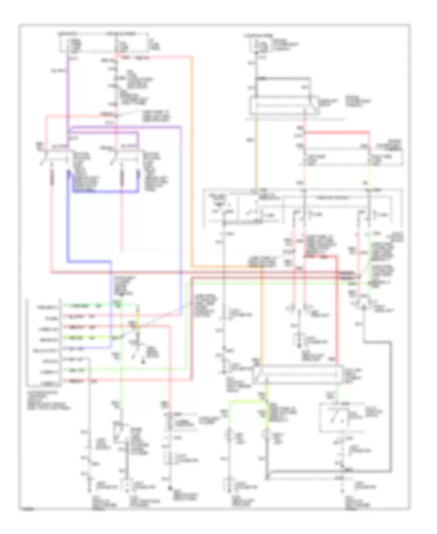
AIR CONDITIONING
A/C Wiring Diagram for Mercury Tracer LS 1998

List of elements for A/C Wiring Diagram for Mercury Tracer LS 1998:
- (behind right side of dash) g201
- (dash panel to headlamp harness, near breakout to multi-function switch) s213
- (dash panel to headlamp harness, near breakout to in-line connector, near clutch pedal position switch) s234
- (engine harness, near breakout to egr vacuum regulator (evr)) s101
- (left front of engine) constant control relay module (ccrm)
- (main harness, in breakout to integrated control panel, near rear window defrost switch)
- (near starter motor) g112
- .33 ohms
- .62 ohms
- 1.38 ohms
- A/c
- A/c clutch field coil
- A/c high pressure switch (left front of engine compartment, near mass air flow sensor)
- A/c low pressure switch (right rear of engine compartment, on a/c accumulator)
- A/c max
- A/c-heater control assembly
- Air cond fuse 15a
- Blower c.b. 30a
- Blower motor
- Blower motor relay
- Blower motor resistor (behind right side of dash, in a/c-heater plenum)
- Blower switch
- C110
- C133
- C147
- C200
- C220
- C240
- C272
- C273
- Cooling fan fuse 40a
- Defrost
- Electric cooling fan
- Engine compartment fuse box
- Engine controls system
- Engine fuse 15a
- Floor flr/def
- Fuel injector fuse 30a
- Fuel pump relay
- Function selector switch
- G100 (left front of engine)
- G112 (near starter motor)
- G200 (behind top of left kick panel)
- Hfc relay
- Hot at all times
- Hot in run
- Hot in start
- Hot in start or run
- I/p fuse panel
- Integrated control panel (icp)
- J/c 3
- J/c 6
- Lfc relay
- Lfc relay control
- Near breakout to egr vacuum regulator (evr)) s106
- Off
- Panel
- Panel floor
- Pcm power relay
- Powertrain control module (pcm) (below center of dash)
- Red
- Relay box (left side of dash, near kick panel)
- S116 (engine harness, near breakout to electric cooling fan)
- S117 (engine harness, near breakout to air conditioning pressure (acp) sensor)
- S204 (engine harness, in breakout to powertrain control module (pcm))
- S238
- Solid state
- Thermal limiter
- Wac relay
- Wiper fuse 20a
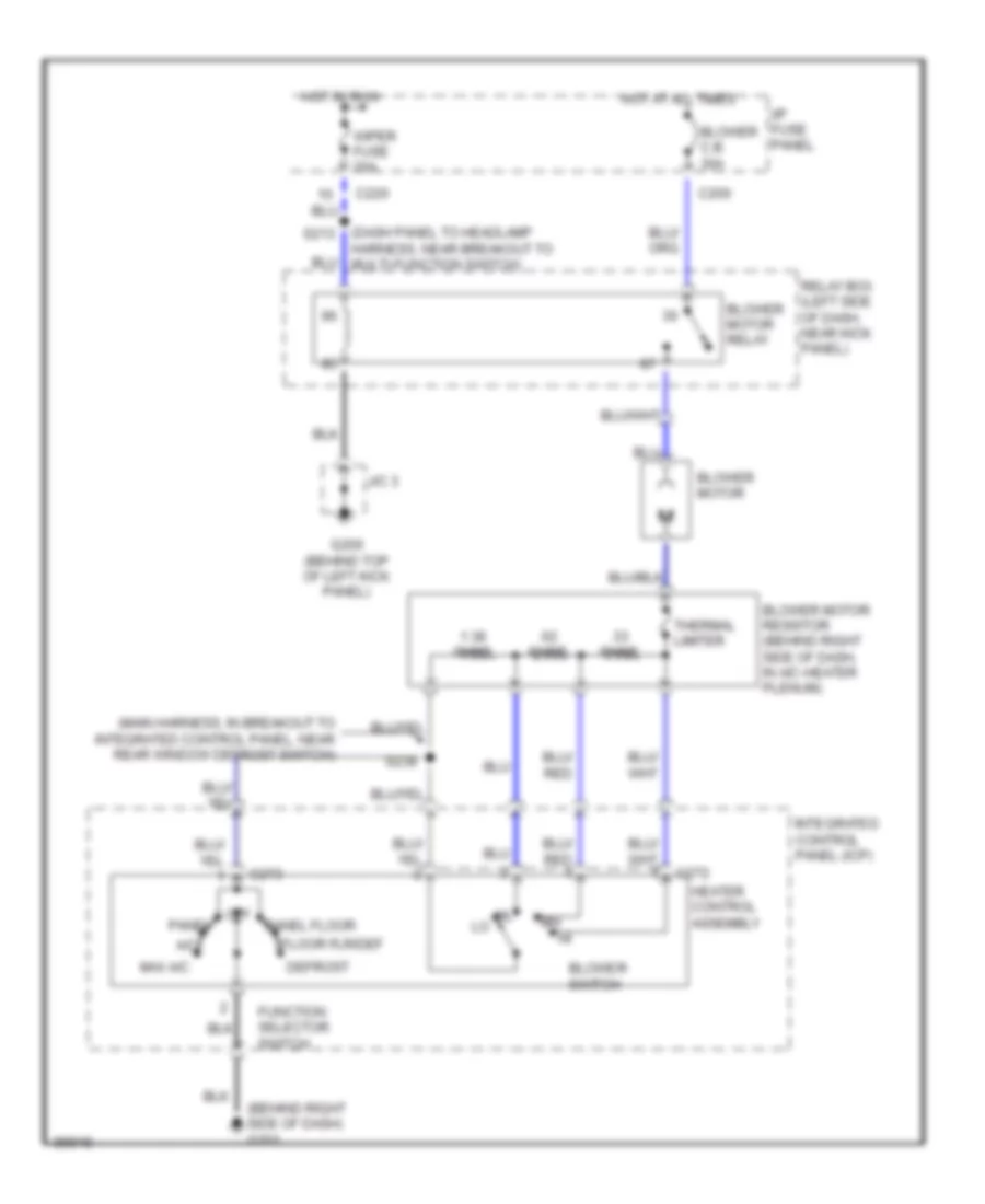
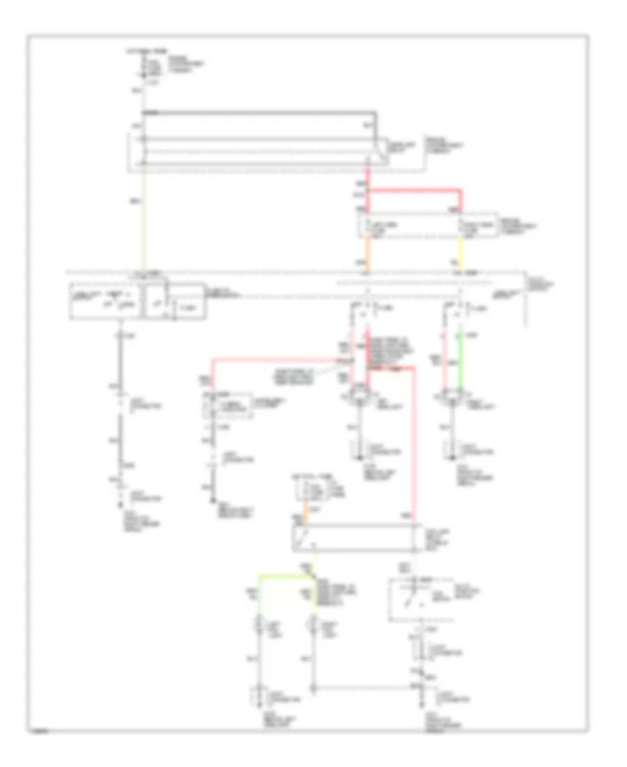
Heater Wiring Diagram for Mercury Tracer LS 1998
List of elements for Heater Wiring Diagram for Mercury Tracer LS 1998:
- (behind right side of dash) g201
- (dash panel to headlamp s213
- (main harness, in breakout to integrated control panel, near rear window defrost switch)
- .33 ohms
- .62 ohms
- 1.38 ohms
- A/c
- Blower c.b. 30a
- Blower motor
- Blower motor relay
- Blower motor resistor (behind right side of dash, in a/c-heater plenum)
- Blower switch
- C200
- C220
- C272
- C273
- Defrost
- Floor flr/def
- Function selector switch
- G200 (behind top of left kick panel)
- Harness, near breakout to multi-function switch)
- Heater control assembly
- Hot at all times
- Hot in run
- I/p fuse panel
- Integrated control panel (icp)
- J/c 3
- Max a/c
- Off
- Panel
- Panel floor
- Relay box (left side of dash, near kick panel)
- S238
- Thermal limiter
- Wiper fuse 20a
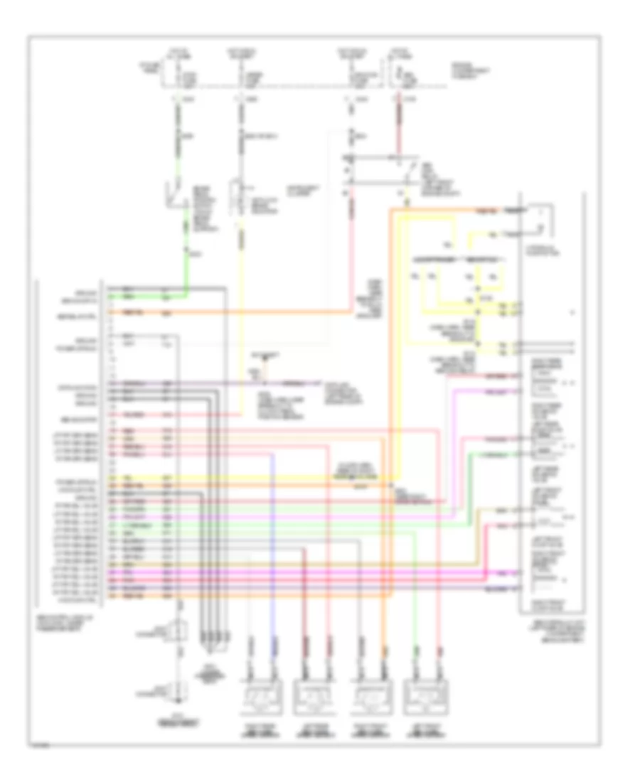
ANTI-LOCK BRAKES
Anti-lock Brake Wiring Diagrams for Mercury Tracer LS 1998
List of elements for Anti-lock Brake Wiring Diagrams for Mercury Tracer LS 1998:
- (dash harn, near breakout to bulk- head grommet)
- (floor harn, rear of right rear door jamb)
- Abs control module (on floor, under passenger seat)
- Abs fuse 60a
- Abs hydraulic unit (left rear of engine compartment, behind battery)
- Abs indicator
- Abs main relay (left front corner of engine compt)
- Abs relay ctrl
- Air cond fuse 15a
- Anti-lock brake indicator
- Anti-theft
- Brake pedal position switch (top of brake pedal support)
- Brk on/off in
- C109
- C240
- C260
- Data link connector (left rear of engine compt)
- Datalink conn
- Engine compartment fuse box
- Escort zx2
- Escort/tracer
- G101 (front of right fender apron)
- G301 (under passenger seat)
- Ground
- Hot at all times
- Hot in run or start
- Hyd pump ctrl
- Hydraulic pump motor
- I/p fuse panel
- Instrument cluster
- Joint connector
- Left front abs wheel speed sensor
- Left front dump valve
- Left front solenoid valve
- Left rear abs wheel speed sensor
- Left rear dump valve
- Left rear solenoid valve
- Lft frt sol valve
- Lft frt spd sens
- Lft rr sol valve
- Lft rr spd sens
- Meter fuse 10a
- Nca
- Pnk
- Power (st/run)
- Red
- Right front abs wheel speed sensor
- Right front dump valve
- Right front solenoid valve
- Right rear abs wheel speed sensor
- Right rear dump valve
- Right rear solenoid valve
- Rt frt sol valve
- Rt frt spd sens
- Rt rr sol valve
- Rt rr spd sens
- S118 (dash harn, near breakout to abs main relay)
- S119 (dash harn, near breakout to grommet)
- S136
- S209
- S220 or s214
- S233
- S234
- S235 (dash harn, near breakout to clutch pedal position sensor)
- S302 (near right crtsy switch)
- S316
- Stop fuse 15a
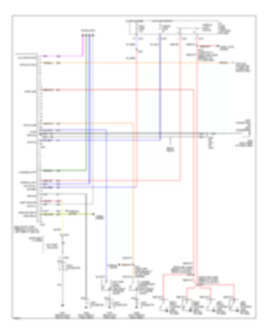
ANTI-THEFT
Anti-theft Wiring Diagram for Mercury Tracer LS 1998
List of elements for Anti-theft Wiring Diagram for Mercury Tracer LS 1998:
- (rear harn, near breakout to left crtsy lmp switch) s303
- (rear harn, near breakout to right crtsy lmp switch) s304
- Anti-theft hood switch (left front of engine compt)
- Anti-theft indicator
- Battery
- C253
- C270
- C404
- C405
- Data link connector (under left side of dash)
- Datalink conn
- Door ajar
- Door locks
- Door locks system
- Exterior lights
- G106 (behind left headlamp)
- G201 (behind right side of dash)
- G405 (right rear of cargo area)
- Ground
- Hood
- Horn relay
- Horns system
- Hot at all times
- Hot in acc or run
- I/p fuse panel (left side of dash)
- Ignition
- Instrument cluster
- Interior light
- Interior lights
- Joint connector
- Joint connector 8 or joint connector 9
- Left front courtesy lamp switch (at jamb)
- Left rear courtesy lamp switch (at jamb)
- Lock all
- Luggage compartment switch (right front of luggage compt)
- Luggage compt
- Mirror fuse 5a
- Parklamp relay
- Remote anti-theft personality module (left rear of vehicle)
- Right front courtesy lamp switch (at jamb)
- Right rear courtesy lamp switch (at jamb)
- Room fuse 10a
- S300
- S310 (wagon only) (rear harn, near breakout to i/p fuse panel)
- S403 or s314 or s422
- S411 (rear harn, near breakout to left rear speaker)
- Sedan/ wagon
- Theft indicatr
- Trunk ajar
- Unlk drvr door
- Unlock all
- Warning chime module
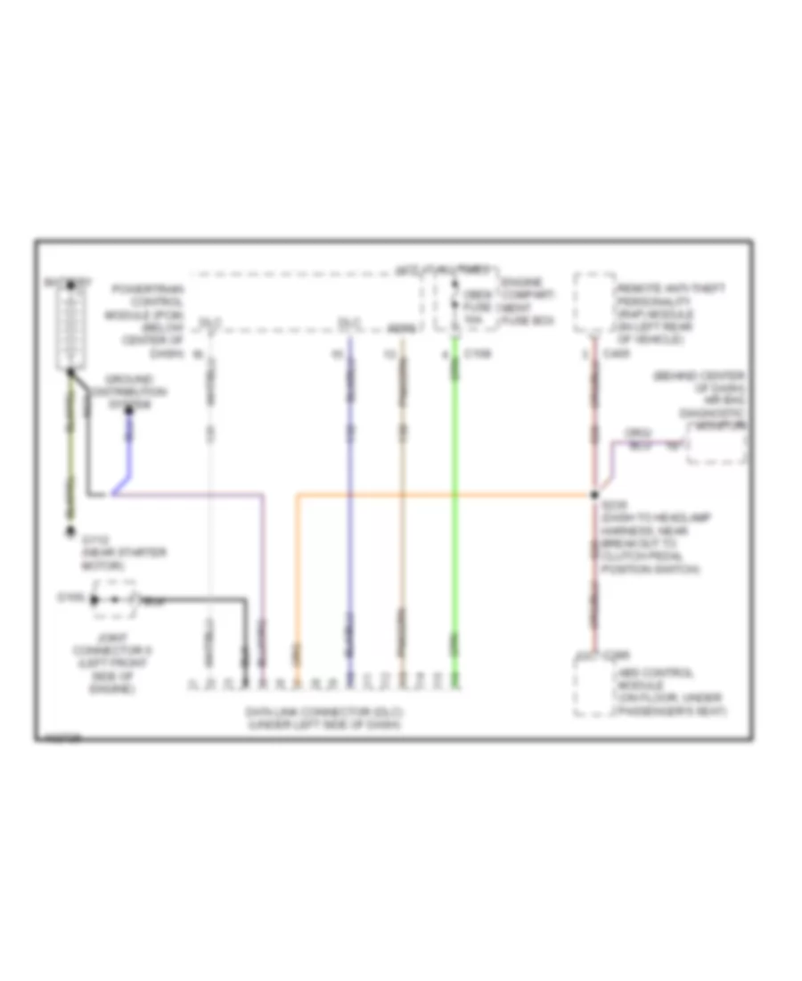
COMPUTER DATA LINES
Computer Data Lines for Mercury Tracer LS 1998
List of elements for Computer Data Lines for Mercury Tracer LS 1998:
- (behind center of dash) air bag diagnostic monitor
- Abs control module (on floor, under passenger's seat)
- Battery
- C108
- C386
- C405
- Clutch pedal position switch)
- Data link connector (dlc) (under left side of dash)
- Dlc +
- Dlc -
- Engine compart- ment fuse box
- Feps
- G100
- G112 (near starter motor)
- Ground distribution system
- Hot at all times
- Joint connector 6 (left front side of engine)
- Nca
- Obdii fuse 10a
- Powertrain control module (pcm) (below center of dash)
- Remote anti-theft personality (rap) module (in left rear of vehicle)
- S235 (dash to headlamp harness, near breakout to
COOLING FAN
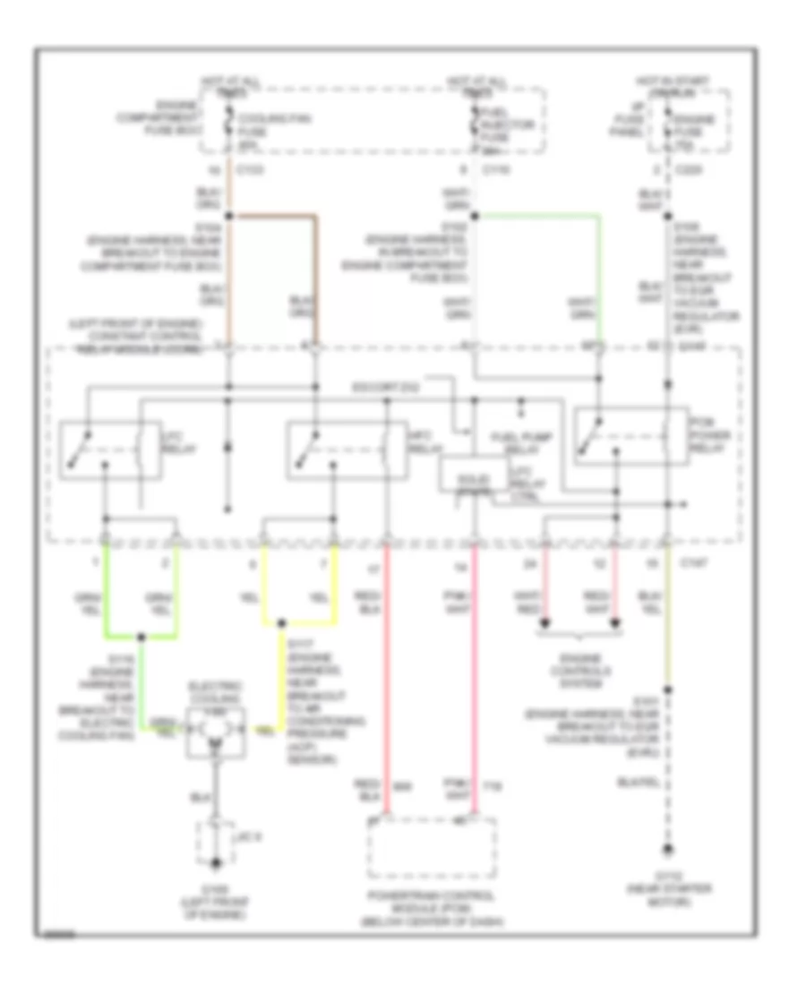
Cooling Fan Wiring Diagram for Mercury Tracer LS 1998
List of elements for Cooling Fan Wiring Diagram for Mercury Tracer LS 1998:
- (left front of engine) constant control relay module (ccrm)
- C110
- C133
- C147
- C220
- Cooling fan fuse 40a
- Electric cooling fan
- Engine compartment fuse box
- Engine controls system
- Engine fuse 15a
- Escort zx2
- Fuel injector fuse 30a
- Fuel pump relay
- G100 (left front of engine)
- G112 (near starter motor)
- Hfc relay
- Hot at all times
- Hot in start or run
- I/p fuse panel
- J/c 6
- Lfc relay
- Lfc relay ctrl
- Pcm power relay
- Powertrain control module (pcm) (below center of dash)
- S101 (engine harness, near breakout to egr vacuum regulator (evr))
- S102 (engine harness, in breakout to engine compartment fuse box)
- S104 (engine harness, near breakout to engine compartment fuse box)
- S116 (engine harness, near breakout to electric cooling fan)
- S117 (engine harness, near breakout to air conditioning pressure (acp) sensor)
- Solid state
CRUISE CONTROL
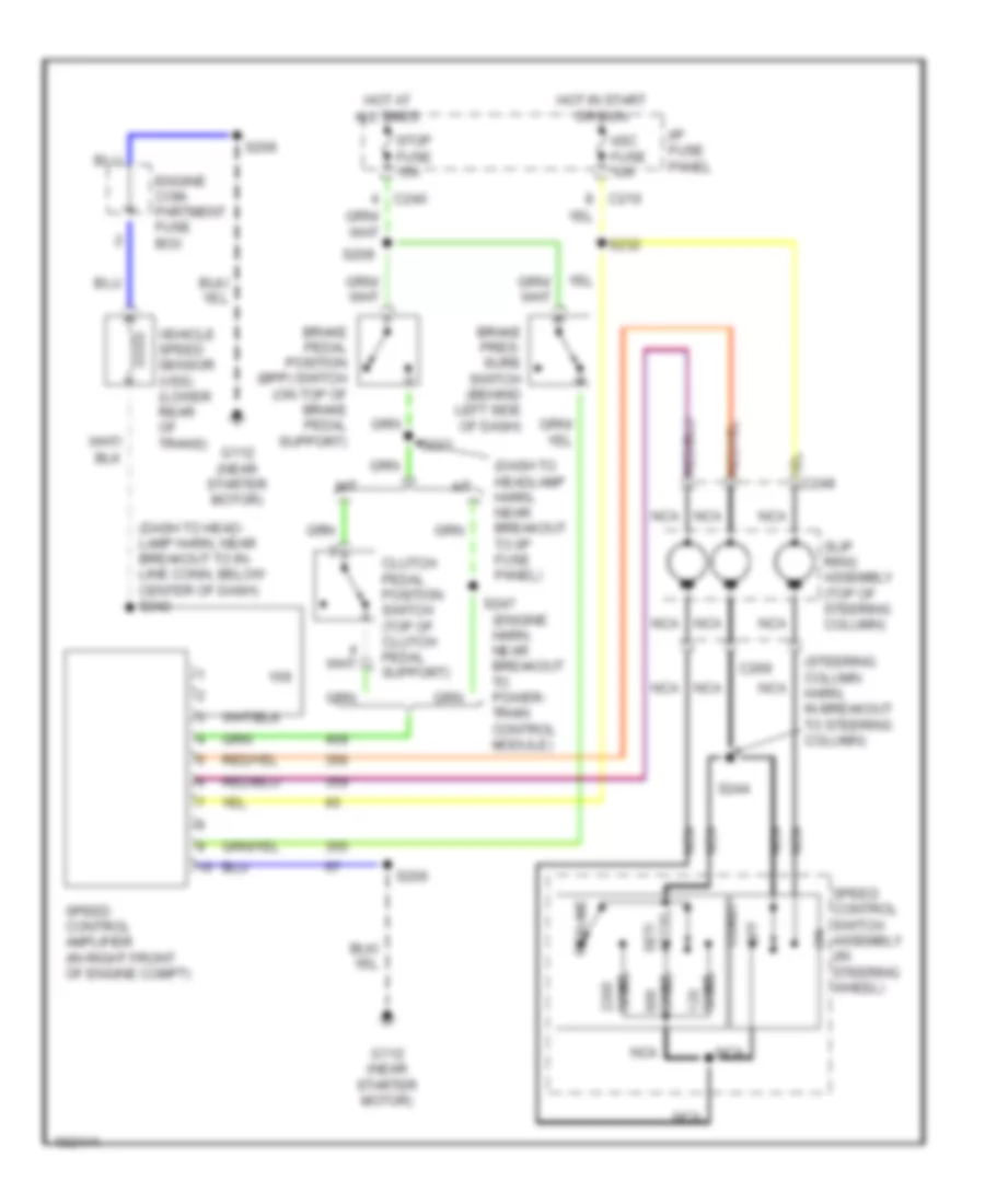
Cruise Control Wiring Diagram for Mercury Tracer LS 1998
List of elements for Cruise Control Wiring Diagram for Mercury Tracer LS 1998:
- (dash to head- lamp harn, near breakout to in- line conn, below center of dash) s242
- (dash to headlamp harn, near breakout to i/p fuse panel)
- (engine harn, near breakout to power- train control module)
- (steering column harn, in breakout to steering column)
- A/t
- Asc fuse 10a
- Brake pedal position (bpp) switch (on top of brake pedal support)
- Brake pres- sure switch (behind left side of dash)
- C210
- C240
- C269
- Clutch pedal position switch (top of clutch pedal support)
- Coast
- Engine com- partment fuse box
- G112 (near starter motor)
- Hot at all times
- Hot in start or run
- I/p fuse panel
- M/t
- Nca
- Off
- Ohms
- Resume
- S206
- S209
- S232
- S233
- S244
- S247
- Set/ accel
- Slip ring assembly (top of steering column)
- Speed control amplifier (in right front of engine compt)
- Speed control switch assembly (in steering wheel)
- Stop fuse 15a
- Vehicle speed sensor (vss) (lower rear of trans)
DEFOGGERS
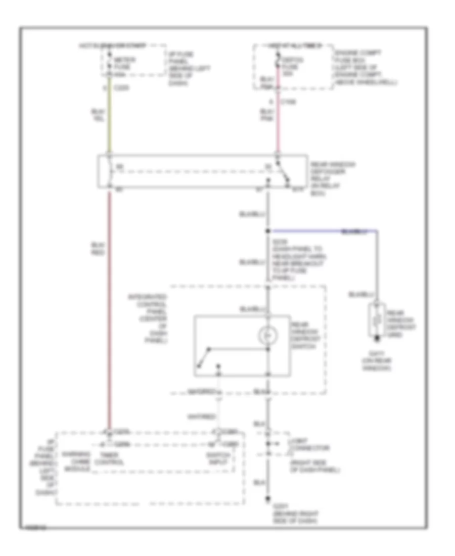
Defogger Wiring Diagram for Mercury Tracer LS 1998
List of elements for Defogger Wiring Diagram for Mercury Tracer LS 1998:
- 87a
- C108
- C220
- C230
- C260
- C290
- Defog fuse 30a
- Engine compt fuse box (left side of engine compt, above wheelwell)
- G201 (behind right side of dash)
- G411 (on rear window)
- Hot at all times
- Hot in run or start
- I/p fuse panel (behind left side of dash)
- Integrated control panel (center of dash panel)
- Joint connector (right side of dash panel)
- Meter fuse 10a
- Rear window defogger relay (in relay box)
- Rear window defrost grid
- Rear window defrost switch
- S239 (dash panel to headlight harn, near breakout to i/p fuse panel)
- Switch input
- Timer control
- Warning chime module
ENGINE PERFORMANCE
2.0L
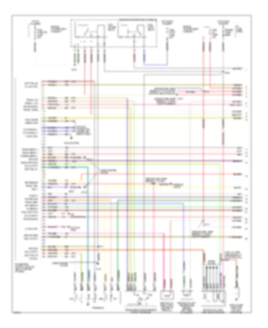
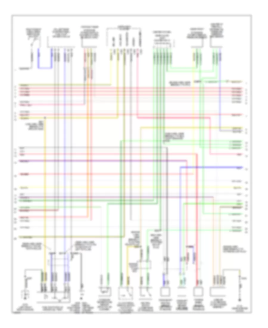
2.0L, Engine Performance Wiring Diagrams (1 of 3) for Mercury Tracer LS 1998
List of elements for 2.0L, Engine Performance Wiring Diagrams (1 of 3) for Mercury Tracer LS 1998:
- (a/t)
- (engine harn, near breakout to constant control relay module)
- (engine harn, near breakout to eng compt fuse box)
- (engine harn, near breakout to pcm)
- (fuel inj harn, near breakout to ignition coil) s207
- (near starter motor)
- A/c on input
- Air conditioning
- Coil output
- Constant control relay module
- Cooling fans
- Crank sens (+)
- Crank sens (-)
- Datalink connector (under left side of dash)
- Dlc #2 bus (+)
- Dlc #2 bus (-)
- Ect sens in
- Egr vac reg
- Egr vacuum regulator (center of firewall)
- Engine compartment fuse box
- Engine coolant temperature sensor (left rear of engine)
- Engine fuse 15a
- Epc
- Eprom pwr
- Exterior lights
- Fuel gauge
- Fuel inj fuse 10a
- Fuel injector fuse 30a
- Fuel pump fuse 30a
- Fuel pump mon
- Fuel pump relay
- G112
- Ground
- Hi fan ctrl
- Ho2s-12
- Hot at all times
- Hot in run or start
- I/p fuse panel
- Iat sens in
- Ignition coil pack (left side of engine)
- Irm solenoid
- Lo fan ctrl
- Maf return
- Mil ind ctrl
- Nca
- Pcm power relay
- Powertrain control module (below center of dash)
- Psp sensor
- Radio noise capacitor (top left of engine)
- Red
- S101
- S102
- S106
- S110 (engine harn, near breakout to eng compt fuse box)
- S112
- S113
- S204
- S231
- Shield ground
- Shift sol #1
- Shift sol #2
- Shift sol #3
- Spark plugs
- Tach output
- Tcc
- Tcc sol
- Tft
- Trans - drive
- Trans - low
- Trans - od
- Trans - rev
- Trans temp
- Transaxle
- Transmission range sensor (top of transaxle)
- Turbine sens (-)
- Vss (-)
2.0L, Engine Performance Wiring Diagrams (2 of 3) for Mercury Tracer LS 1998
List of elements for 2.0L, Engine Performance Wiring Diagrams (2 of 3) for Mercury Tracer LS 1998:
- (center of dash,
- (center of firewall) differential pressure feedback egr sensor
- (dash harn, near breakout to eng compt grommet) s128
- (eng harn, near breakout to octane adjust plug)
- (engine harn, near breakout to octane adjust plug)
- (engine harn, near breakout to octane adjust plug) s264
- (engine harn, near breakout to pcm)
- (near front
- (on left rear quarter panel) fuel pump driver module
- (rear harn, near breakout to 10-pin inline conn at left "b" pillar)
- (rear harn, near breakout to fuel pump module)
- (right side of cargo area) inertia fuel shutoff
- (sedan) (left rear corner
- (top right rear
- C252
- C253
- C254
- Camshaft position sensor (left rear of engine)
- Clutch pedal position switch (on top of clutch pedal support)
- Crankshaft
- Engine compt fuse box
- Fuel input
- Fuel pump module (inside fuel tank)
- G100 (left front side of engine)
- G112 (near starter motor)
- G404 g405 (wagon) (right rear of cargo area) of trunk)
- Instrument cluster
- Intake air temperature sensor (front of air cleaner)
- Mass air flow sensor (in air cleaner assembly)
- Mil lamp
- Nca
- Near floor) joint connector 10
- Neutral switch (lower rear of transaxle)
- Of engine) intake manifold runner control solenoid (imrc)
- Of engine) power steering pressure sensor
- Pnk
- Position sensor (left front of engine)
- Red
- S207
- S207 (main harn, near breakout to ground g206)
- S226
- S228
- S230
- S301
- S315
- S423
- Sensor (on top of transaxle)
- Speedo
- Tachometer
- Turbine speed
- Upshift lamp
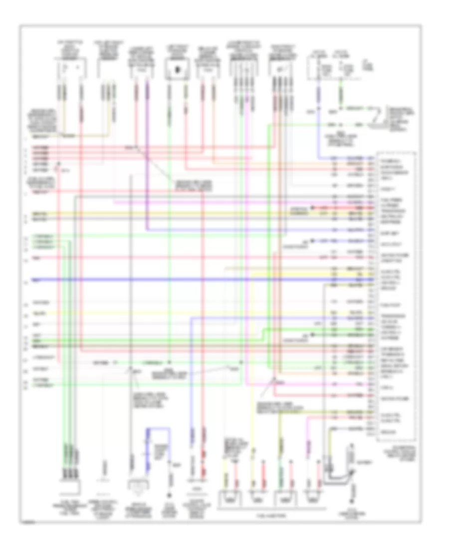
2.0L, Engine Performance Wiring Diagrams (3 of 3) for Mercury Tracer LS 1998
List of elements for 2.0L, Engine Performance Wiring Diagrams (3 of 3) for Mercury Tracer LS 1998:
- (a/t)
- (below air cleaner assembly) evap canister purge valve
- (dash harn, near breakout to 16-pin conn at lower center of dash)
- (engine harn, near breakout to 16-pin conn below center of dash)
- (engine harn, near breakout to 16-pin inline conn at right rear of engine compartment)
- (engine harn, near breakout to brake fluid level switch)
- (engine harn, near breakout to pcm)
- (fuel inj harn, near breakout to fuel inj #3)
- (left front of engine) knock sensor
- (lower front of engine, in exhaust manifold) heated oxygen sensor no 12
- (m/t)
- (on throttle body) throttle position sensor
- (right front of engine) heated oxygen sensor no 11
- (top left front of engine) injection pressure sensor
- (under left rear corner of vehicle) evap canister vent solenoid
- A/c cutout
- A/c press
- Air conditioning
- Battery
- Brake pedal postion (bpp) switch (on brake pedal support)
- Brake sw in
- Cam pos (+)
- Cam pos (-)
- Egr press
- Engine compt fuse box
- Evap purge
- Evap vent
- Fuel injectors
- Fuel press
- Fuel pump
- Fuel tank pressure sensor (inside fuel tank)
- G112 (near starter motor)
- Ground
- Ho2s-11
- Hot at all times
- Htr-11
- Htr-12
- I/p fuse panel
- Iac valve
- Idle air control valve (top right rear of engine)
- Ignition power
- Inj #1 ctrl
- Inj #2 ctrl
- Inj #3 ctrl
- Inj #4 ctrl
- Inj press
- Knock sensor
- Maf sensor
- Nca
- Neutral sw
- Pnk
- Power b(+)
- Powertrain control module (below center of dash)
- Red
- Ref voltage
- Room fuse 15a
- S111
- S114
- S124
- S129
- S206
- S209
- S218
- S224
- S225
- S233 (dash harn, near breakout to i/p fuse panel)
- S242
- S266
- Signal return
- Speed control amplifier (right front of engine compt)
- Starting/ charging
- Stop fuse 15a
- Tan
- Tp sensor in
- Trans range
- Turbine (+)
- Upshift ind
- Vehicle speed sensor (lower rear of transaxle)
- Vss (+)
EXTERIOR LIGHTS
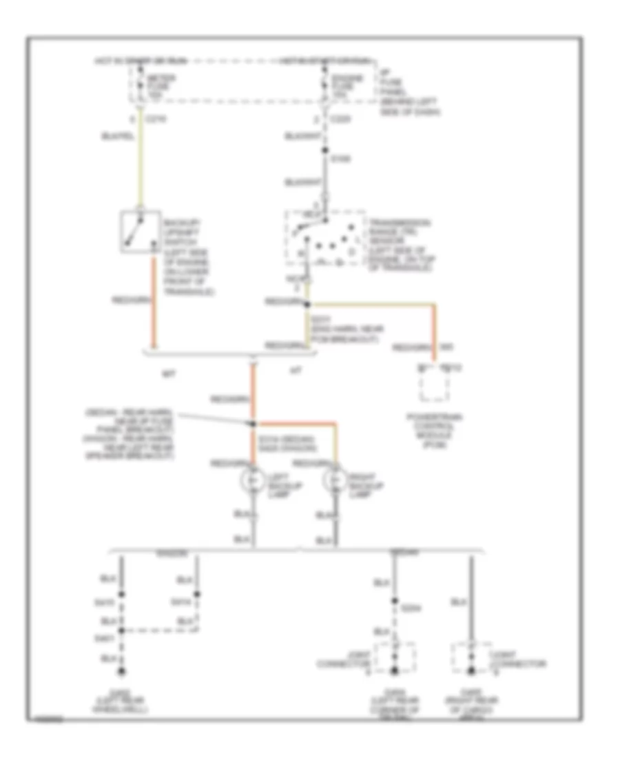
Back-up Lamps Wiring Diagram for Mercury Tracer LS 1998
List of elements for Back-up Lamps Wiring Diagram for Mercury Tracer LS 1998:
- (sedan - rear harn, near i/p fuse panel breakout) (wagon - rear harn, near left rear speaker breakout)
- A/t
- Backup/ upshift switch (left side of engine, on lower front of transaxle)
- C210
- C212
- C220
- Engine fuse 15a
- G402 (left rear wheelwell)
- G404 (left rear corner of trunk)
- G405 (right rear of cargo area)
- Hot in start or run
- I/p fuse panel (behind left side of dash)
- Joint connector
- Left backup lamp
- M/t
- Meter fuse 10a
- Nca
- Powertrain control module (pcm)
- Right backup lamp
- S106
- S204
- S314 (sedan) s420 (wagon)
- S401
- S414
- S415
- Sedan
- Transmission range (tr) sensor (left side of engine, on top of transaxle)
- Wagon
Exterior Lamps Wiring Diagram, Sedan for Mercury Tracer LS 1998
List of elements for Exterior Lamps Wiring Diagram, Sedan for Mercury Tracer LS 1998:
- (dash panel to hdlmp harn, near breakout to multi- function switch) s251
- (dash to hdlmp harn, near breakout to engine compt fuse box)
- (dash to hdlmp harn, near breakout to engine compt grommet)
- (dash to hdlmp harn, near breakout to pass air bag) s248
- (in relay box) parklamp relay
- (rear harn, near breakout to hi mount stoplamp) s405
- (rear harn, near breakout to left rear courtesy lamp switch)
- Brake pedal position switch (on top of brake pedal support)
- C210
- C220
- C240
- C249
- C251
- C253
- C260
- C270
- C290
- C295
- C296
- C404
- Electronic flasher (in relay box)
- G101 (front of right front fender)
- G106 (behind left headlamp)
- G200 (behind top of left kick panel)
- G201 (behind right side of dash)
- G404 (left rear corner of trunk)
- G405 (right rear of cargo area)
- Hazard fuse 15a
- Hazard switch
- Head
- Hi mount stop lamp
- Hot at all times
- Hot in run or start
- I/p fuse panel (behind left side of dash)
- Instrument cluster
- Interior lights (instrument illumination)
- Joint connector
- Left front park/ turn lamp
- Left front side marker/ turn lamp
- Left rear park/ stop/ turn lamp
- Left turn ind
- License lamps
- Meter fuse 10a
- Multi- function switch
- Off
- Park
- Remote anti-theft personality module (in left rear of vehicle)
- Right front park/ turn lamp
- Right front side marker/ turn lamp
- Right rear park/ stop/ turn lamp
- Right turn ind
- S115
- S125
- S200
- S209
- S216
- S306
- S308 (rear harn, near breakout to left courtesy lamp)
- S402
- S405
- Stop fuse 15a
- Tail fuse 15a
- Turn signal switch
- Warning chime module
Exterior Lamps Wiring Diagram, Wagon for Mercury Tracer LS 1998
List of elements for Exterior Lamps Wiring Diagram, Wagon for Mercury Tracer LS 1998:
- (dash panel to hdlmp harn, near breakout to multi- function switch) s251
- (dash to hdlmp harn, near breakout to engine compt fuse box)
- (dash to hdlmp harn, near breakout to engine compt grommet)
- (dash to hdlmp harn, near breakout to pass air bag) s248
- (rear harn, near breakout to joint conn 9) s418
- (rear harn, near breakout to rap module) s417
- Brake pedal position switch (on top of brake pedal support)
- C210
- C220
- C240
- C249
- C251
- C253
- C260
- C270
- C290
- C295
- C296
- C404
- Electronic flasher (in relay box)
- G101 (front of right front fender)
- G106 (behind left headlamp)
- G200 (behind top of left kick panel)
- G201 (behind right side of dash)
- G402 (left rear wheelwell)
- G406 (center of liftgate)
- Hazard fuse 15a
- Hazard switch
- Head
- Hi mount stop lamp
- Hot at all times
- Hot in run or start
- I/p fuse panel (behind left side of dash)
- Instrument cluster
- Interior lights (instrument illumination)
- Joint connector
- Left front park/ turn lamp
- Left front side marker/ turn lamp
- Left rear park/ stop/ turn lamp
- Left rear side marker lamp
- Left rear speaker) s413
- Left rear turn/ hazard lamp
- Left turn ind
- License lamps
- Meter fuse 10a
- Multi- function switch
- Multi-function switch
- Off
- Park
- Parklamp relay (in relay box)
- Remote anti-theft personality module (in left rear of vehicle)
- Right front park/ turn lamp
- Right front side marker/ turn lamp
- Right rear park/ stop/ turn lamp
- Right rear side marker lamp
- Right rear turn/ hazard lamp
- Right turn ind
- S115
- S125
- S200
- S209
- S216
- S306
- S306 (rear harn, near breakout to left rear ctsy lamp sw)
- S401
- S402
- S405
- S406
- S414
- S415
- Stop fuse 15a
- Tail fuse 15a
- Turn signal switch
- Warning chime module
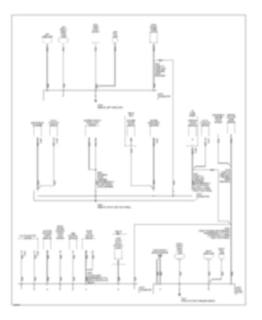
GROUND DISTRIBUTION
Ground Distribution Wiring Diagram (1 of 3) for Mercury Tracer LS 1998
List of elements for Ground Distribution Wiring Diagram (1 of 3) for Mercury Tracer LS 1998:
- (right front side of engine) g120
- Abs control module
- Air bag diagnostic monitor
- Anti- theft hood switch
- Blower motor relay
- C230
- C246
- C247
- C249
- C251
- C264
- C295
- Daytime running lamps module
- Door lock/ unlock relay
- Ector 5, upper right kick panel)
- Electronic flasher
- Engine coolant level switch
- G101 (front of right fender apron)
- G106 (behind left headlamp)
- G200 (behind top of left kick panel)
- I/p fuse panel
- Joint conn- ector
- Joint connector
- Left fog lamp
- Left front park/ turn lamp
- Left headlamp
- Master window/ door lock switch
- Multi- function switch
- Multi-function switch
- One touch down control unit
- Relay box
- Right fog lamp
- Right front park/ turn lamp
- Right headlamp
- Right power window/ door lock switch
- S100 (dash to headlamp harness, near grommet)
- S200 (dash to headlamp harness, near breakout to joint connector 5, upper right kick panel)
- S203 (dash to headlamp harness, near grommet)
- S500 (driver's door harness, near breakout to left front door speaker)
- Warning chime module
- Wind- shield wiper motor
- Windshield washer pump motor
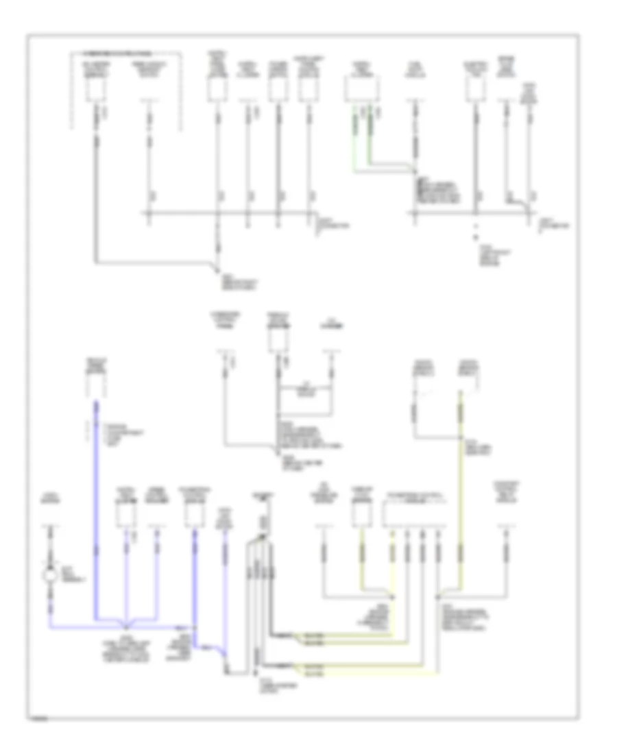
Ground Distribution Wiring Diagram (2 of 3) for Mercury Tracer LS 1998
List of elements for Ground Distribution Wiring Diagram (2 of 3) for Mercury Tracer LS 1998:
- A/c high pressure switch
- A/c-heater control assembly
- Battery
- Brake fluid level switch
- C252
- C253
- C254
- C273
- C274
- C305
- Cd changer
- Constant control relay module
- Data link conn- ector
- Electric cooling fan
- Engine compartment fuse box
- Fuel pump module
- G100 (left front side of engine)
- G112 (near starter motor)
- G201 (behind right side of dash)
- G206 (behind center of dash)
- Horn switch
- Instru- ment cluster
- Instru- ment panel cigar lighter
- Instrument panel dimming module
- Integrated control panel
- Joint connector
- Knock sensor shield 1
- Knock sensor shield 2
- Mass air flow sensor
- Nca
- Power mirror switch
- Powertrain control module
- Premium sound amplifier
- Rear window defrost switch
- S101 (engine harness, near breakout to egr vacuum regulator (evr))
- S134 (eng harn, near pcm)
- S204 (engine harness, in breakout to pcm)
- S205 (engine harness, near grommet)
- S206 (dash to headlamp harness, near breakout to c202, center console)
- S207 (main harness, near breakout to ground g206, center of dash)
- S208 (main harness, near breakout to ground c206, behind center of dash)
- Slip ring assembly
- Speed control amplifier
- Vehicle speed sensor
- W/ premium sound
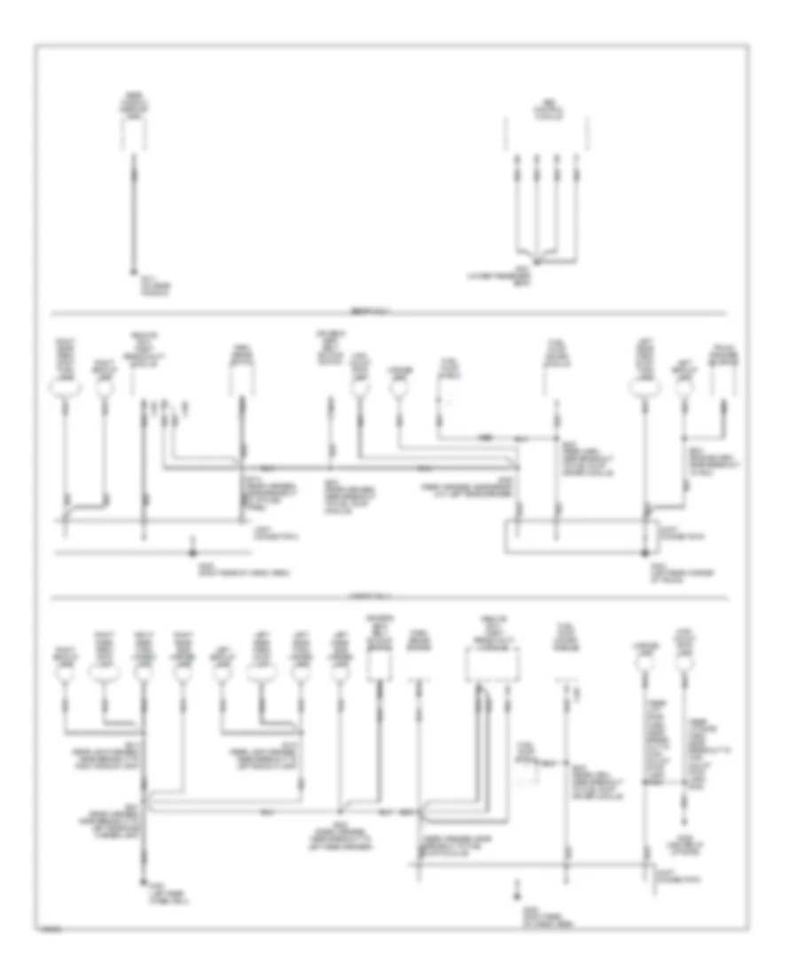
Ground Distribution Wiring Diagram (3 of 3) for Mercury Tracer LS 1998
List of elements for Ground Distribution Wiring Diagram (3 of 3) for Mercury Tracer LS 1998:
- (rear harness, near breakout to fuel pump module)
- (rear lift- gate harn, near break- out to high mount stop lamp) s405
- (rear liftgate harn, near breakout to high mount stop lamp) s406
- Abs control module
- C404
- C405
- C407
- Driver's seat belt buckle switch
- Fuel pump driver module
- Fuel pump shield
- G301 (under passenger seat)
- G402 (left rear wheelwell)
- G404 (left rear corner of trunk)
- G405 (right rear of cargo area)
- G406 (center of liftgate)
- G411 (on rear window)
- High mount stop lamp
- Joint connector 8
- Joint connector 9
- Left backup lamp
- Left rear park/ stop lamp
- Left rear park/ stop/ turn lamp
- Left rear side marker lamp
- Left rear turn/ hazard lamp
- License lamp
- Nca
- Park sense switch
- Rear window defrost grid
- Remote anti- theft personality module
- Right backup lamp
- Right rear park/ stop lamp
- Right rear park/ stop/ turn lamp
- Right rear side marker lamp
- Right rear turn/ hazard lamp
- S204 (engine harn, near breakout to pcm)
- S314 (rear harness, near breakout to i/p fuse panel)
- S401 (rear harness, near breakout to left rear side marker lamp)
- S402 (rear harness, near break- out left rear speaker)
- S402 (rear harness, near breakout to left rear speaker)
- S403
- S403 (rear harness, near breakout to fuel pump module)
- S414 (rear lamp harness, near breakout to right backup lamp)
- S415 (rear lamp harness, near breakout to left backup lamp)
- S423 (rear harn, near breakout to fuel pump driver module)
- S424
- Sedan only
- Trunk release solenoid
- Wagon only
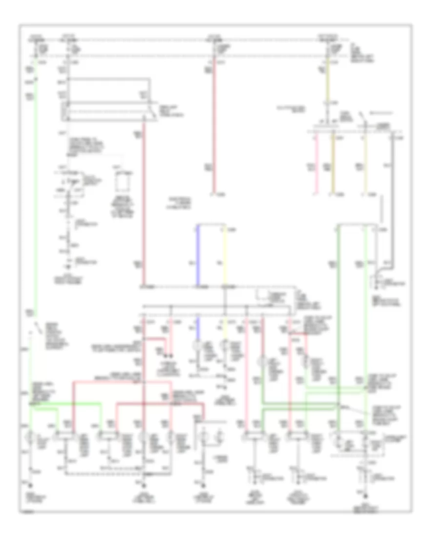
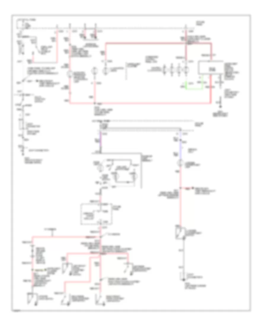
HEADLIGHTS
Headlight Wiring Diagram, with DRL for Mercury Tracer LS 1998
List of elements for Headlight Wiring Diagram, with DRL for Mercury Tracer LS 1998:
- (dash panel to headlamp harn, near air bag diagnostic monitor)
- (dash panel to headlamp harn, near grommet)
- (dash panel to headlamp harn, near j/c 5 breakout) s259
- (dash panel to headlamp harn, red near windshield wiper motor breakout) s122
- 10a
- Brake fluid level switch (on brake master cylinder)
- Brake ind
- C157
- C210
- C227
- C249
- C250
- C251
- C253
- Daytime running lamp (drl) relay (left) (behind left side of dash, near kick panel)
- Daytime running lamp (drl) relay (right) (behind right side of dash, near top of kick panel)
- Daytime running lamps (drl) module (behind right side of dash, top of kick panel)
- Drl fuse (in right rear corner of eng compt)
- Drl resistor (on rear right strut tower)
- Engine compartment fuse box
- Flash
- Flash to pass switch
- Fog fuse 10a
- Fog lamp relay (in rekay box)
- Fog switch
- G100 (left front side of engine)
- G101 (front of right fender apron)
- G106 (behind left headlamp)
- G201 (behind right side of dash)
- Ground
- Head
- Headlamp relay
- Hi beam in
- Hi beam ind
- Hi-beam indicator
- Hot at all times
- Hot in run
- I/p fuse panel
- Instrument cluster
- Instrument cluster system (brake indicator)
- Joint conn- ector 5
- Joint connector
- Left fog light
- Left head fuse 10a
- Left headlight
- Lo beam in
- Main fuse 100a
- Main light switch
- Multi- function switch
- Nca
- Off
- Park
- Park brake switch
- Park brk in
- Pass air bag breakout)
- Power
- Rear wiper fuse 10a
- Red
- Relay output
- Right fog light
- Right head fuse 10a
- Right headlight
- S103
- S105
- S121
- S123
- S200
- S219
- S241
- S246 (dash panel to headlamp harn, near j/c 7 breakout)
- S260
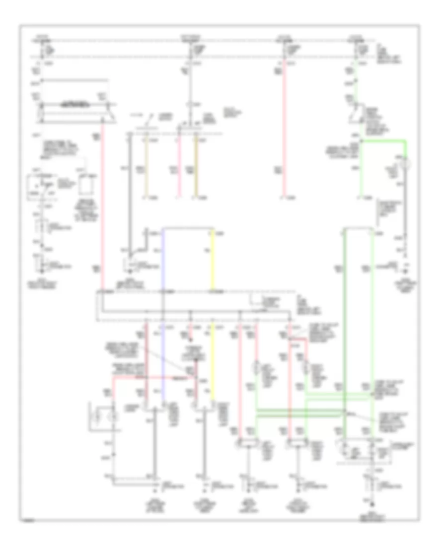
Headlight Wiring Diagram, without DRL for Mercury Tracer LS 1998
List of elements for Headlight Wiring Diagram, without DRL for Mercury Tracer LS 1998:
- (dash panel to headlamp harn, near grommet)
- (dash panel to headlamp harn, red near windshield wiper motor breakout) s122
- C157
- C227
- C249
- C250
- C251
- C253
- Engine compartment fuse box
- Flash
- Flash to pass switch
- Fog fuse 10a
- Fog lamp relay (in relay box)
- Fog switch
- G101 (front of right fender apron)
- G106 (behind left headlamp)
- G201 (behind right side of dash)
- Head
- Headlamp relay
- Hi-beam indicator
- Hot at all times
- I/p fuse panel
- Instrument cluster
- Joint connector
- Left fog light
- Left head fuse 10a
- Left headlight
- Main fuse 100a
- Main light
- Multi- function switch
- Off
- Park
- Red
- Right fog light
- Right head fuse 10a
- Right headlight
- S103
- S105
- S121
- S200
- S246 (dash panel to headlamp harn, near j/c 7 breakout)
- Switch
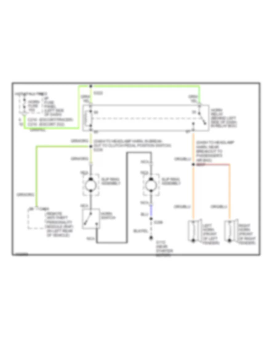
HORN
Horn Wiring Diagram for Mercury Tracer LS 1998
List of elements for Horn Wiring Diagram for Mercury Tracer LS 1998:
- (dash to headlamp harn, in break- out to clutch pedal position switch) s236
- (dash to headlamp harn, near breakout to passenger's air bag) s237
- (escort/tracer) (escort zx2)
- C210 c210
- C404
- G112 (near starter motor)
- Horn fuse 15a
- Horn relay (behind left side of dash, in relay box)
- Horn switch
- Hot at all times
- I/p fuse panel (left side of dash)
- Left horn (front of left fender)
- Nca
- Remote anti-theft personality module (rap) (in left rear of vehicle)
- Right horn (front of right fender)
- S206
- S222
- Slip ring assembly
INSTRUMENT CLUSTER
Instrument Cluster Wiring Diagram for Mercury Tracer LS 1998
List of elements for Instrument Cluster Wiring Diagram for Mercury Tracer LS 1998:
- (1998-00)
- (2000 only)
- (2001)
- (dash to hdlmp harn, near breakout to airbag monitor)
- (rear harn, near breakout to left rear spkr) s411
- A10
- A11
- A12
- Airbag ind
- Anti- slosh/ bulb proveout module
- Anti-lock brake control module (on floor, under passenger's seat)
- Anti-lock ind
- Anti-theft ind
- B10
- B11
- B12
- B13
- Battery junction box (left side of engine compt, above wheel- well)
- Brake fluid level switch (on brake master cylinder)
- Brake ind
- C10
- C108
- C111
- C210
- C212
- C230
- C252 (conn a)
- C253 (conn b)
- C254 (conn c)
- C260
- C386
- Central junction box (behind left side of dash)
- Charge ind
- Check engine coolant ind (2000)
- Check engine ind
- Daytime running lamps module (behind right side of dash, top of kick panel)
- Engine coolant level switch (top of coolant reservoir)
- Engine coolant temp gauge
- Engine oil pressure ind
- Engine oil pressure switch (on engine, near oil filter)
- Exterior lights system
- Fuel cap off ind (2001)
- Fuel gauge
- Fuel pump module (in fuel tank)
- G100 (left front side of engine)
- G101
- G112 (near starter motor)
- G201 (behind right side of dash)
- Headlights system
- Hi beam ind
- Hot at all times
- Hot in run or start
- Illumination
- Instrument cluster
- Instrumentation engine coolant temperature sender (on left rear of engine)
- Interior lights system
- Joint connector
- Joint connector 1 (front of right fender apron)
- Joint connector 7 (right side of dash)
- Left turn ind
- Liftgate ajar ind
- Liftgate latch switch (at rear latch)
- Low fuel ind
- M/t only
- Meter fuse 10a
- Nca
- Obd ii fuse 10a
- Park brake switch (below center console)
- Pnk
- Powertrain control module (below center of dash)
- Red
- Remote anti-theft personality module (in right rear of vehicle)
- Right turn ind
- S100
- S207
- S214
- S220
- S229
- S240 (main harn, near breakout to cluster conn c252)
- S241 (dash to hdlmp harn, near breakout to air bag diag monitor)
- S242
- Seat belt ind
- Speedometer
- Starting/ charging system
- Starting/charging system
- Tachometer
- Upshift ind
- Vehicle speed sensor (on lower rear of transaxle)
- W/ drl
- W/o drl
- Warning chime module
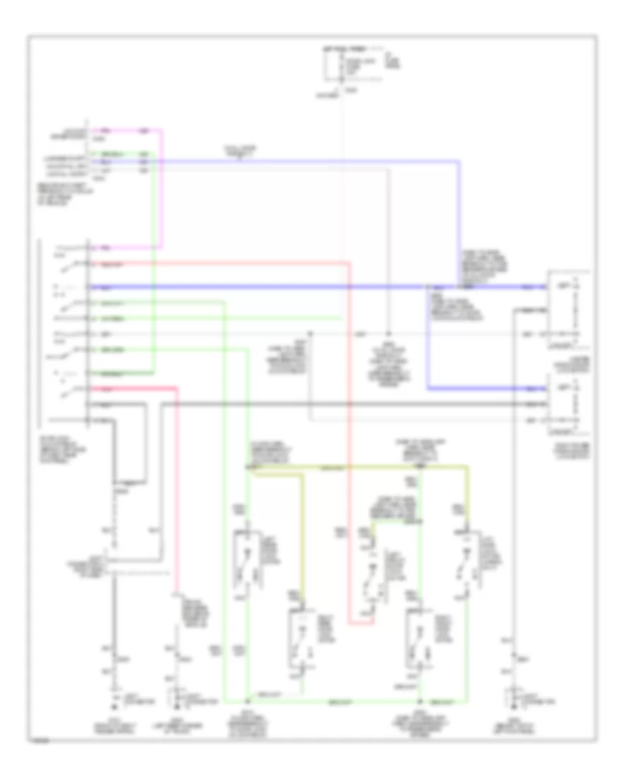
INTERIOR LIGHTS
Interior Light Wiring Diagram for Mercury Tracer LS 1998
List of elements for Interior Light Wiring Diagram for Mercury Tracer LS 1998:
- (dash panel to headlamp harness, near multi- function switch breakout)
- (rear harn, near right front door courtesy lamp switch breakout)
- Automatic transaxle selector illumination lamp
- C210
- C220
- C232
- C251
- C252
- C260
- C270
- C274
- C290
- Control illumination
- Dome lamp
- Dome lamp switch
- Dome/map lamp assembly
- Door
- Exterior lights system
- G101 (front of right fender apron)
- G201 (behind right side of dash)
- G404 (left rear corner of trunk)
- Head
- Hot at all times
- I/p fuse panel
- Illumination lamps
- Instrument cluster
- Instrument cluster system
- Instrument panel dimming module (behind dash, left of steering column)
- Integrated control panel (icp)
- Joint connector (right side of dash)
- Joint connector 1
- Joint connector 7 (right side of dash)
- Joint connector 9
- Left
- Left front door courtesy lamp switch
- Left rear door courtesy lamp switch
- Liftgate latch switch
- Luggage compartment lamp
- Luggage compartment switch
- Map lamp switches
- Multi- function switch
- Nca
- Off
- Park
- Park lamp relay (in relay box)
- Red
- Remote anti- theft personality (rap) module
- Remote keyless entry diode (in left rear of vehicle)
- Right
- Right front door courtesy lamp switch
- Right rear door courtesy lamp switch
- Room fuse 10a
- S200
- S245 (main harn, near i/p fuse panel breakout)
- S251
- S300
- S304
- S306 (rear harn, near left rear courtesy lamp switch breakout)
- S411 (rear harn, near left rear speaker breakout)
- S411 (rear liftgate harn, near luggage compt lamp switch breakout)
- Sedans only
- Solid state
- Tail fuse 15a
- W/ wagons
- Warning chime module
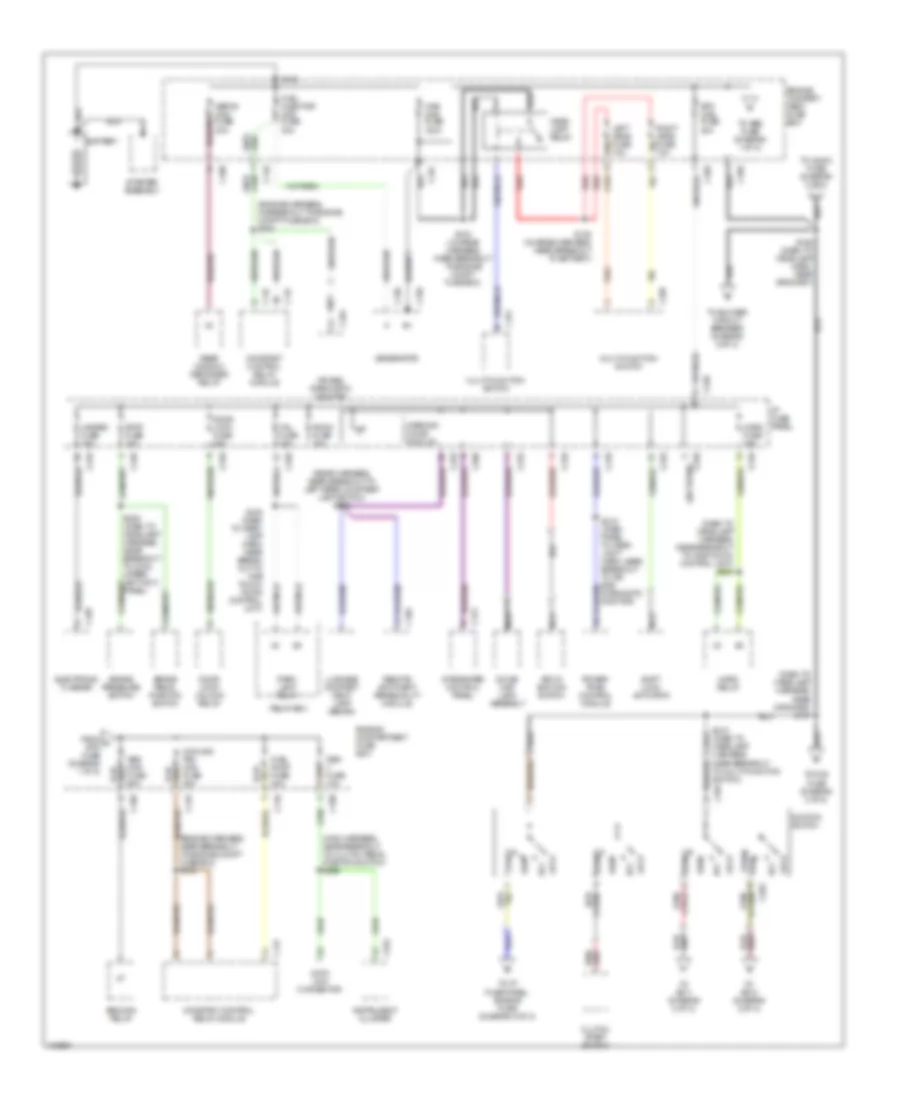
POWER DISTRIBUTION
Power Distribution Wiring Diagram (1 of 2) for Mercury Tracer LS 1998
List of elements for Power Distribution Wiring Diagram (1 of 2) for Mercury Tracer LS 1998:
- (dash to headlamp harness, near breakout to one touch control unit) s222
- (dash to headlamp harness, near grommet) s127
- (engine harness, in breakout to engine compt fuse box) s102
- (engine harness, near breakout to engine compt fuse box) s104
- (main harness, near breakout to clutch pedal position switch) s229
- (not used)
- (rear harness, near breakout to left rear courtesy lamp switch) s300
- Abs main relay
- Abs maxi fuse 60a
- Acc
- Air bag diagnostic monitor
- Battery
- Brake pedal position switch
- Brake pressure switch
- Btn maxi fuse 40a
- C108
- C109
- C110
- C133
- C147
- C156
- C157
- C159
- C160
- C210
- C220
- C232
- C240
- C250
- C251
- C252
- C260
- C264
- C270
- C274
- C281
- C283
- C295
- C404
- Clutch start switch
- Constant control relay module
- Cooling fan maxi fuse 40a
- Crn
- Data link connector
- Defog maxi fuse 30a
- Dome/ map lamp assembly
- Door lock fuse 30a
- Door lock/ unlock relay
- Electronic flasher
- Engine compart- ment fuse box
- Engine compartment fuse box
- From a btn fuse (diagram 1 of 2)
- Fuel injector maxi fuse 30a
- Fuel pump fuse 30a
- Generator
- Hazard fuse 15a
- Head- lamp relay
- Horn fuse 15a
- Horn relay
- I/p fuse panel
- Ignition switch
- Instrument cluster
- Integrated control panel
- Key in ignition switch
- Left head fuse 10a
- Lock
- Luggage compart- ment lamp (sedan)
- Main maxi fuse 100a
- Multi-function switch
- Nca
- Obd ii fuse 10a
- Park lamp relay
- Power- train control module
- Rear window defogger relay
- Red
- Relay box
- Remote anti-theft personality module
- Right head fuse 10a
- Room fuse 10a
- Run
- S103 (charge harness, near breakout to engine compt fuse box)
- S105 (charge harness, near breakout to battery)
- S126 (dash to headlamp harn, near grommet)
- S209 (dash to headlamp harness, near breakout to c233, upper left kick panel)
- S210 (dash to headlamp harness, near breakout to multi-function switch)
- S216 (dash to head- lamp harn, near break- out to one touch down control unit)
- S218 (dash panel to head- light harn, near breakout to air bag diagnostic monitor)
- Shift lock actuator
- Start
- Starter assembly
- Stop fuse 15a
- Tail fuse 15a
- To abs fuse (diagram 1 of 2)
- To audio fuse (diagram 2 of 2)
- To blower circuit breaker (diagram 2 of 2)
- To fog fuse (diagram 2 of 2)
- To i/p fuse panel, engine fuse (diagram 2 of 2)
- To s211 (diagram 2 of 2)
- To s212 (diagram 2 of 2)
- Warning chime module
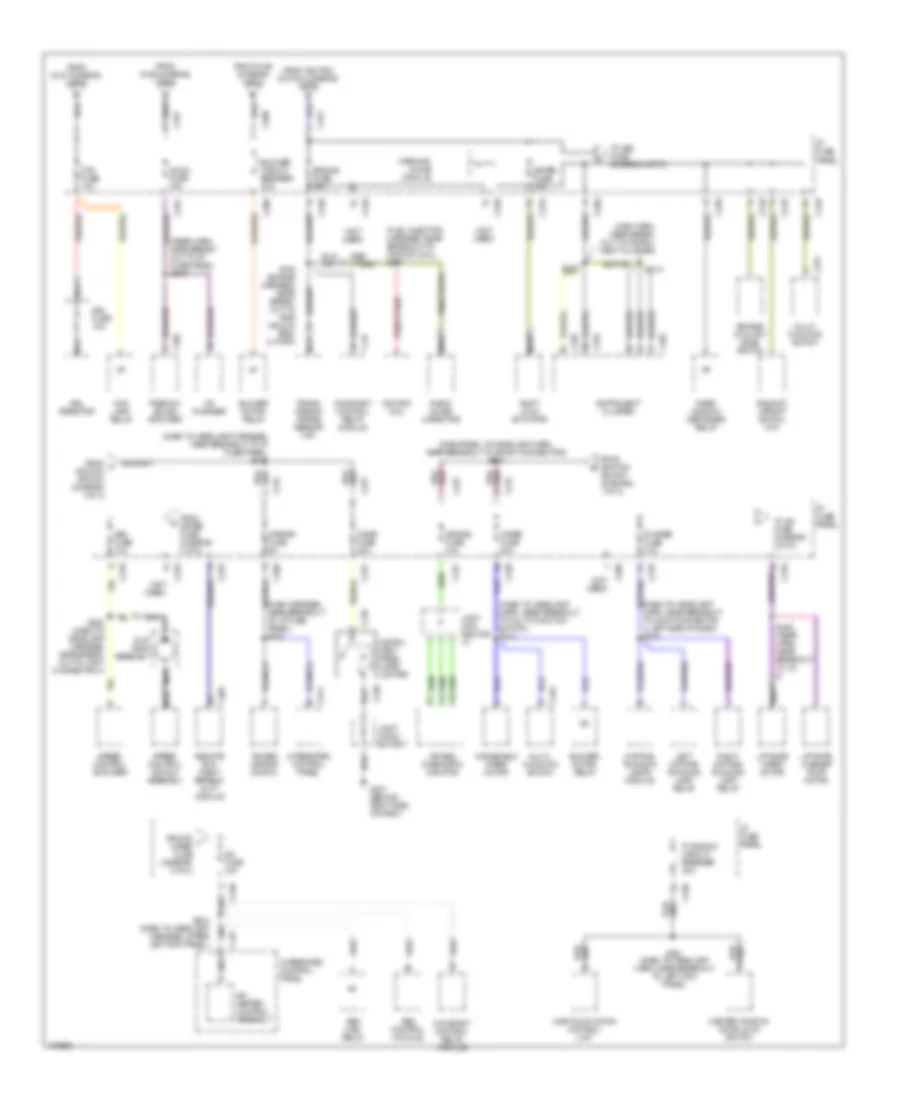
Power Distribution Wiring Diagram (2 of 2) for Mercury Tracer LS 1998
List of elements for Power Distribution Wiring Diagram (2 of 2) for Mercury Tracer LS 1998:
- (dash to headlamp harn, near breakout to joint connector 4, left side of dash) s219
- (dash to headlamp harn, near breakout to multi-function switch) s213
- (dash to headlamp harness, near breakout to i/p fuse panel) s211
- (dashpanel to headlamp harn, near breakout to short connector) s212
- (fuel injector harness, near breakout to ignition coil) s107
- (main harn, near break- out to instru- ment cluster)
- (main harness, near breakout to i/p fuse panel) s223
- (not used)
- (rear harn, near break- out to i/p fuse panel) s215
- A/c fuse 10a
- A/c- heater control assembly
- Abs control module
- Abs main relay
- Air bag diagnostic monitor
- Air bag fuse 10a
- Asc fuse 10a
- Audio fuse 15a
- Backup/ upshift switch (m/t)
- Bkl/ red
- Blower circuit breaker 30a
- Blower motor relay
- C147
- C200
- C210
- C220
- C226
- C227
- C231
- C239
- C240
- C246
- C251
- C252
- C253
- C254
- C260
- C270
- C274
- C277
- C305
- C405
- Cd changer
- Cigar fuse 20a
- Constant control relay module
- Daytime running lamps module
- Drl fuse 10a
- Drl resistor
- Engine coolant level switch
- Engine fuse 15a
- Fog fuse 10a
- Fog lamp relay
- From f ignition switch (diagram 1 of 2)
- From ignition switch (diagram 1 of 2)
- From meter fuse (diagram 2 of 2)
- From r i wiper fuse (diagram 2 of 2)
- From s126 (diagram 1 of 2)
- From s127 (diagram 1 of 2)
- G201 (behind right side of dash)
- I/p fuse panel
- Ignition coil
- Instru- ment panel cigar lighter
- Instrument cluster
- Integrated control panel
- Joint con- nector
- Joint conn- ector 7
- Left daytime running lamp relay
- Liftgate washer pump motor
- Liftgate wiper motor
- Master window/ door lock switch
- Meter fuse 10a
- Mirror fuse 5a
- Multi- function switch
- Nca
- One touch down control unit
- P window circuit breaker 30a
- Power mirror switch
- Premium sound amplifier
- R wiper fuse 10a
- Radio noise capacitor
- Rear window defogger relay
- Red bkl/
- Remote anti- theft person- ality module
- Right daytime running lamp relay
- S106 (engine harness, near break- out to egr vacuum reg- ulator)
- S214
- S220
- S221 (dash to headlamp harn, near breakout to left kick panel)
- S232 (dash to headlamp harness, near break- out to joint connector 4)
- S234 (dash to headlamp harness, upper left kick panel)
- S409 (rear harn, near breakout to j/c 8)
- Shift lock actuator
- Slip ring assembly
- Speed control amplifier
- Speed control switch assembly
- To a/c fuse (diagram 2 of 2)
- To asc fuse (diagram 2 of 2)
- Trans- mission range sensor (a/t)
- Warning chime module
- Windshield wiper motor
- Wiper fuse 20a
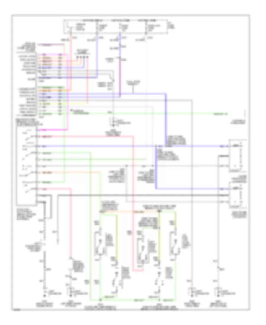
POWER DOOR LOCKS
Door Lock Wiring Diagram for Mercury Tracer LS 1998
List of elements for Door Lock Wiring Diagram for Mercury Tracer LS 1998:
- (dash to head- lamp harn, near breakout to pas- senger's air bag) (w/ all door rke only) s256
- (dash to head- lamp harn, near breakout to pas- senger's air bag) s256
- (dash to headlamp harn, near breakout to joint conn 3) s252
- (floor harn, near breakout to door lock/ unlock relay) s311
- (w/ all door rke only)
- C240
- C404
- C405
- Door lock fuse 30a
- Door lock/ unlock relay (behind left side of dash, near kick panel)
- G101 (front of right fender apron)
- G200 (behind top of left kick panel)
- G404 (left rear corner of trunk)
- Hot at all times
- I/p fuse panel
- Joint connector
- Joint connector 5 (right side of dash)
- Left front door lock motor
- Left rear door lock motor
- Lift- gate lock motor (wagon only)
- Lock
- Lock all door
- Luggage compt
- Master window/door lock switch
- Nca
- Pnk
- Remote anti-theft personality module (in left rear of vehicle)
- Right front door lock motor
- Right power window/door lock switch
- Right rear door lock motor
- S200
- S204
- S249
- S254 (dash to headlamp harn, near breakout to passenger's air bag)
- S255 (dash to head- lamp harn, near breakout to door lock/unlock relay)
- S257 (dash to head- lamp harn, near breakout to door lock/ unlock relay)
- S258 (w/ all door rke only) (dash to head- lamp harn, near breakout to passenger's air bag)
- S312 (floor harn, near breakout to door lock/ unlock relay)
- S500
- Trunk release solenoid (rear of vehicle)
- Unlock
- Unlock all dr
- Unlock driver door
Keyless Entry Wiring Diagram for Mercury Tracer LS 1998
List of elements for Keyless Entry Wiring Diagram for Mercury Tracer LS 1998:
- (dash to head- lamp harn, near breakout to pas- senger's air bag) s256
- (dash to headlamp harn, near breakout to joint conn 3) s252
- (floor harn, near breakout to door lock/ unlock relay) s311
- (w/ all door rke only)
- (wagon only)
- (wagon) (sedan)
- Anti-theft system
- Battery
- C240
- C260
- C270
- C404
- C405
- Data link con
- Data link connector (under left side of dash)
- Door ajar
- Door lock fuse 30a
- Door lock/ unlock relay (behind left side of dash, near kick panel)
- Exterior lights system
- G101 (front of right fender apron)
- G200 (behind top of left kick panel)
- G404 (left rear corner of trunk)
- G405 (right rear of cargo area)
- Ground
- Hood/trunk
- Horn relay
- Horn relay (in relay box)
- Hot at all times
- Hot in acc or run
- I/p fuse panel
- Interior light
- Joint connector
- Joint connector 5 (right side of dash)
- Left front door lock motor
- Left rear door lock motor
- Lift- gate lock motor (wagon only)
- Lock
- Lock all door
- Luggage compt
- Master window/door lock switch
- Mirror fuse 5a
- Nca
- Park lamp rly
- Pnk
- Power
- Remote anti-theft personality module (in left rear of vehicle)
- Right front door lock motor
- Right power window/door lock switch
- Right rear door lock motor
- Room fuse 10a
- S200
- S204
- S249
- S254 (dash to headlamp harn, near breakout to passenger's air bag)
- S255 (dash to head- lamp harn, near breakout to door lock/unlock relay)
- S257 (dash to head- lamp harn, near breakout to door lock/ unlock relay)
- S258 (dash to head- lamp harn, near breakout to passenger's air bag)
- S300
- S306
- S312 (floor harn, near breakout to door lock/unlock relay)
- S430 s314
- S500
- Theft indicatr
- Trunk ajar
- Trunk release solenoid (rear of vehicle)
- Unlock
- Unlock all dr
- Unlock l door
- Warning chime module
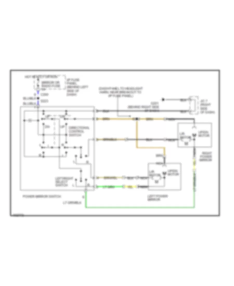
POWER MIRRORS
Power Mirror Wiring Diagram for Mercury Tracer LS 1998
List of elements for Power Mirror Wiring Diagram for Mercury Tracer LS 1998:
- (dash panel to headlight harn, near breakout to i/p fuse panel)
- C260
- Directional control switch
- G201 (behind right side of dash)
- Hot in accy or run
- I/p fuse panel (behind left side of dash)
- J/c 7 (right side of dash)
- L/r motor
- Left power mirror
- Left/right select switch
- Mirror or radio fuse 5a
- Nca
- Power mirror switch
- Right power mirror
- S223
- S262
- Up/dn m motor
- Up/dn motor
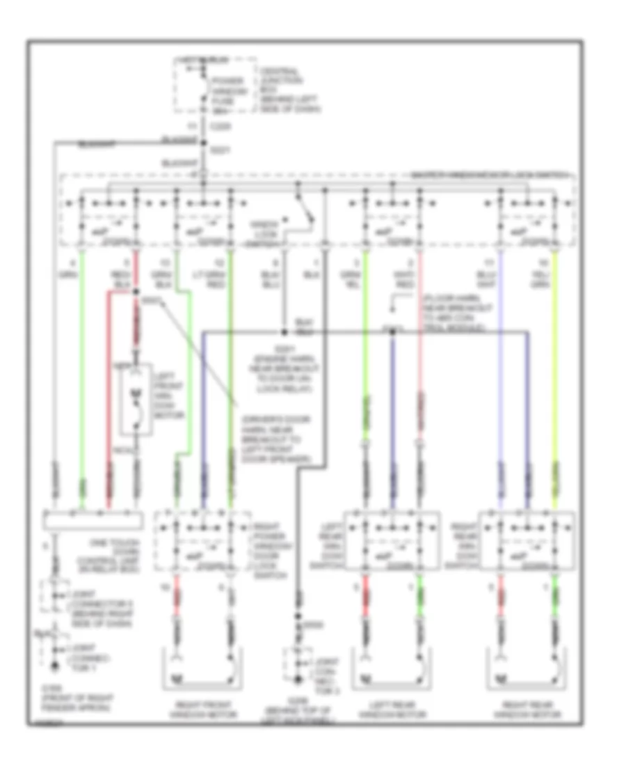
POWER WINDOWS
Power Window Wiring Diagram for Mercury Tracer LS 1998
List of elements for Power Window Wiring Diagram for Mercury Tracer LS 1998:
- (driver's door harn, near breakout to left front door speaker)
- (floor harn, near breakout to abs con- trol module)
- C220
- Central junction box (behind left side of dash)
- Down
- G106 (front of right fender apron)
- G200 (behind top of left kick panel)
- Hot in run
- Joint con- nec- tor 3
- Joint connec- tor 1
- Joint connector 5 (behind right side of dash)
- Left front win- dow motor
- Left rear win- dow switch
- Left rear window motor
- Master window/door lock switch
- Nca
- One touch down control unit (in relay box)
- Power window fuse 30a
- Red
- Right front window motor
- Right power window/ door lock switch
- Right rear win- dow switch
- Right rear window motor
- S221
- S261 (engine harn, near breakout to door un- lock relay)
- S313
- S500
- S507
- Wndw lock switch
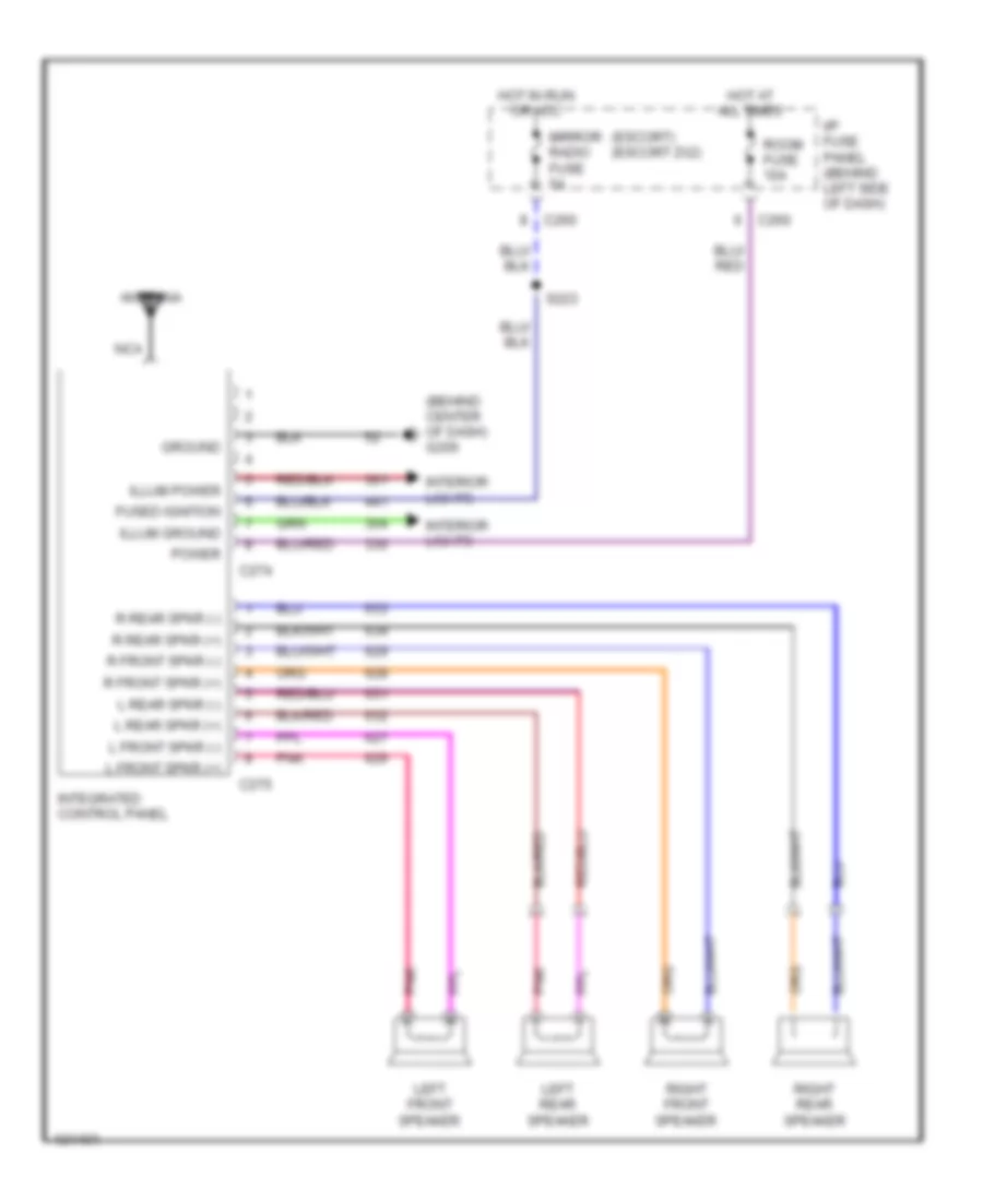
RADIO
Base Radio for Mercury Tracer LS 1998
List of elements for Base Radio for Mercury Tracer LS 1998:
- (behind center of dash) g206
- (escort) (escort zx2)
- Antenna
- C260
- C274
- C275
- Fused ignition
- Ground
- Hot at all times
- Hot in run or acc
- I/p fuse panel (behind left side of dash)
- Illum ground
- Illum power
- Integrated control panel
- Interior lights
- L front spkr (+)
- L front spkr (-)
- L rear spkr (+)
- L rear spkr (-)
- Left front speaker
- Left rear speaker
- Mirror radio fuse 5a
- Nca
- Pnk
- Power
- R front spkr (+)
- R front spkr (-)
- R rear spkr (+)
- R rear spkr (-)
- Right front speaker
- Right rear speaker
- Room fuse 10a
- S223
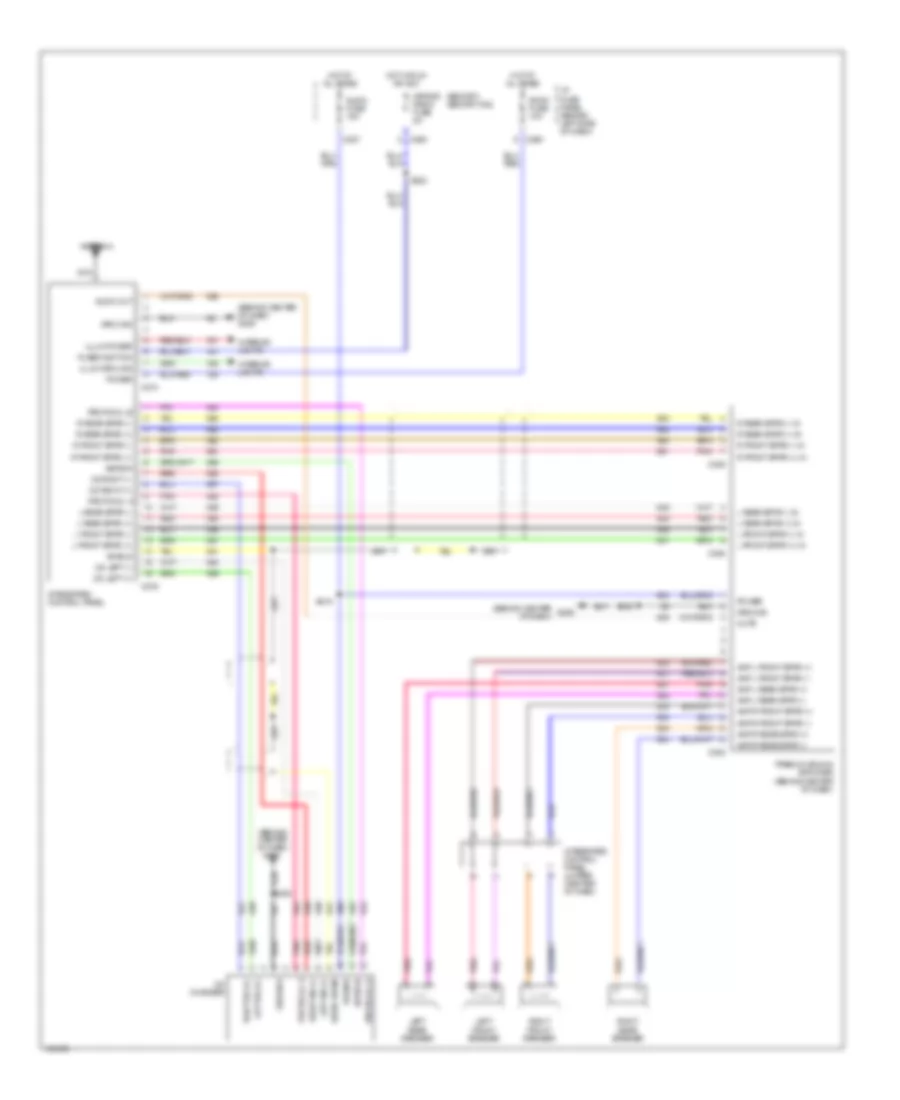
Premium Sound Radio Wiring Diagram for Mercury Tracer LS 1998
List of elements for Premium Sound Radio Wiring Diagram for Mercury Tracer LS 1998:
- (behind center of dash)
- (behind center of dash) g206
- (escort) (escort zx2)
- Amp l front spkr (+)
- Amp l front spkr (-)
- Amp l rear spkr (+)
- Amp l rear spkr (-)
- Amp r front spkr (+)
- Amp r front spkr (-)
- Amp r rear spkr (+)
- Amp r rear spkr (-)
- Antenna
- Asyson
- Audio drain
- Audio fuse 15a
- Audio out
- C227
- C260
- C274
- C276
- C305
- C306
- Cd changer
- Cd left (+)
- Cd left (-)
- Cd right (+)
- Cd right (-)
- Fused ignition
- G206
- Ground
- Hot at all times
- Hot in run or acc
- I/p fuse panel (behind left side of dash)
- Illum ground
- Illum power
- Integrated control panel
- Integrated control panel jumper (center of dash)
- Interior lights
- L front spkr (+)
- L front spkr (+) in
- L front spkr (-)
- L front spkr (-) in
- L rear spkr (+)
- L rear spkr (+) in
- L rear spkr (-)
- L rear spkr (-) in
- Left front speaker
- Left rear speaker
- Left sig (+)
- Left sig (-)
- Mirror radio fuse 5a
- Mute
- Nca
- Pnk
- Power
- Premium sound amplifier (behind center of dash)
- Protocol a
- Protocol b
- R front spkr (+)
- R front spkr (+) in
- R front spkr (-)
- R front spkr (-) in
- R rear spkr (+)
- R rear spkr (+) in
- R rear spkr (-)
- R rear spkr (-) in
- Red
- Right front speaker
- Right rear speaker
- Right sig (+)
- Right sig (-)
- Room fuse 10a
- S208
- S215
- S223
- Shield
SHIFT INTERLOCKS
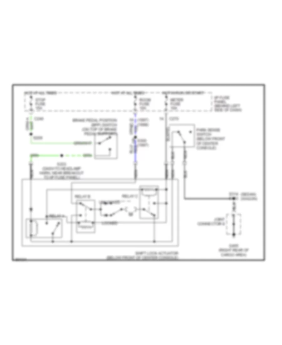
Shift Interlock Wiring Diagram for Mercury Tracer LS 1998
List of elements for Shift Interlock Wiring Diagram for Mercury Tracer LS 1998:
- (1998)
- (sedan) (wagon)
- Brake pedal position (bpp) switch (on top of brake pedal support)
- C240
- C270
- G405 (right rear of cargo area)
- Hot at all times
- Hot in run or start
- I/p fuse panel (behind left side of dash)
- Joint connector 8
- Locked
- Meter fuse 10a
- Nca
- Park sense switch (below front of center console)
- Relay a
- Relay b
- Relay c
- Room fuse 10a
- S209
- S233 (dash to headlamp harn, near breakout to i/p fuse panel)
- S300 (1997)
- S314 s403
- Shift lock actuator (below front of center console)
- Stop fuse 15a
- Unlocked
STARTING/CHARGING
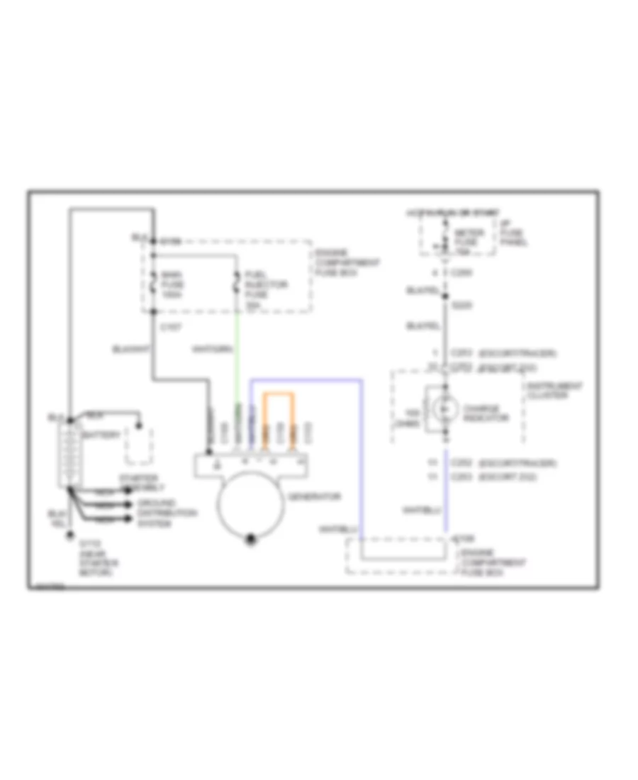
Charging Wiring Diagram for Mercury Tracer LS 1998
List of elements for Charging Wiring Diagram for Mercury Tracer LS 1998:
- (escort zx2)
- (escort/tracer)
- Battery
- C108
- C153
- C156
- C157
- C159
- C160
- C252
- C253
- C260
- Charge indicator
- Engine compartment fuse box
- Fuel injector fuse 30a
- G112 (near starter motor)
- Generator
- Ground distribution system
- Hot in run or start
- I/p fuse panel
- Instrument cluster
- Main fuse 100a
- Meter fuse 10a
- Nca
- Ohms
- S220
- Starter assembly
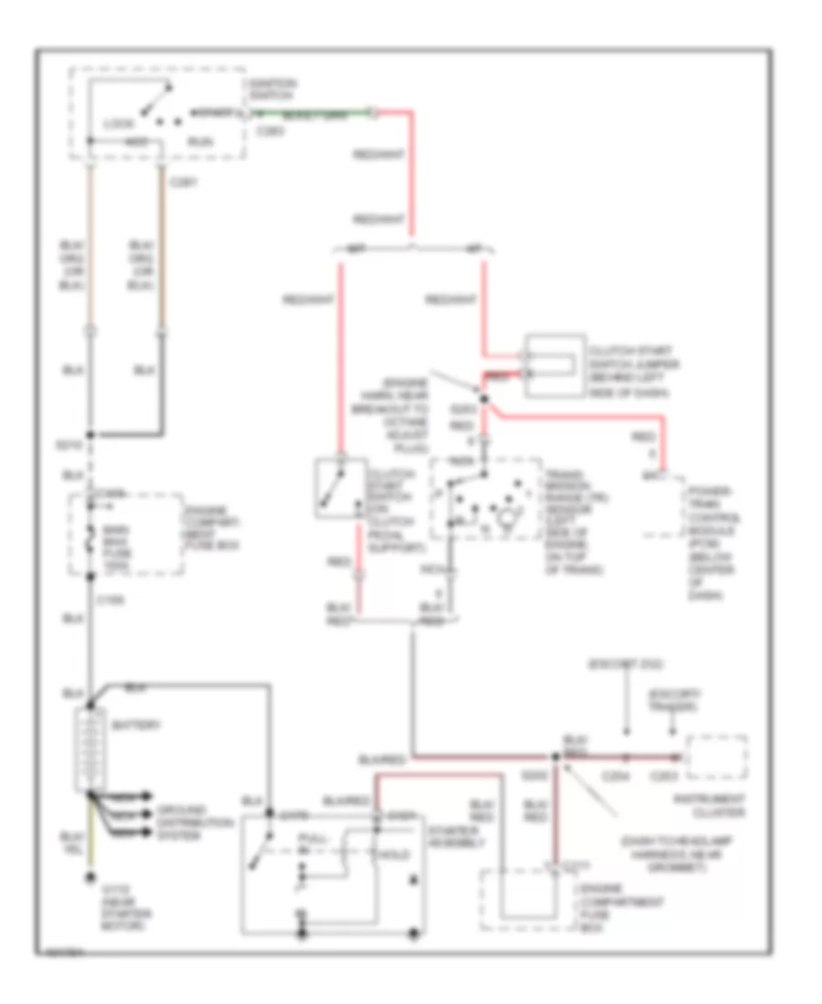
Starting Wiring Diagram for Mercury Tracer LS 1998
List of elements for Starting Wiring Diagram for Mercury Tracer LS 1998:
- (dash to headlamp harness, near grommet)
- (engine harn, near breakout to octane adjust plug)
- (escort zx2)
- (escort/ tracer)
- A/t
- Acc
- Battery
- C109
- C111
- C121
- C156
- C179
- C253
- C254
- C281
- C283
- Clutch start switch (on clutch pedal support)
- Clutch start switch jumper (behind left
- Engine compart- ment fuse box
- Engine compartment fuse box
- G112 (near starter motor)
- Ground distribution system
- Hold
- Ignition switch
- Instrument cluster
- Lock
- M/t
- Main maxi fuse 100a
- Nca
- Power- train control module (pcm) (below center of dash)
- Pull- in
- Red
- Run
- S202
- S210
- S263
- Side of dash)
- Start
- Starter assembly
- Trans- mission range (tr) sensor (left side of engine, on top of trans)
SUPPLEMENTAL RESTRAINTS
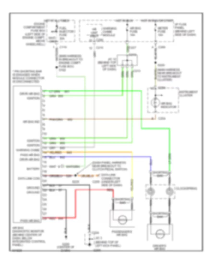
Supplemental Restraint Wiring Diagram for Mercury Tracer LS 1998
List of elements for Supplemental Restraint Wiring Diagram for Mercury Tracer LS 1998:
- (behind top of left kick panel)
- (dash panel harness, near breakout to clutch pedal switch)
- (main harness, in breakout to engine compt fuse box) s102
- * pin shorting bar is engaged when module connector is disconnected
- * red
- A/b unit input
- Air bag diagnostic monitor (behind center of dash, below integrated control panel)
- Air bag fuse 10a
- Air bag ind
- Air bag indicator
- Battery
- C110
- C210
- C213
- C224
- C254
- C255
- C260
- C290
- Clockspring
- Data link con
- Data link connector (under left side of dash)
- Driver's air bag
- Drvr air bag
- Fuel injector fuse 30a
- G200
- G206 (center of dash)
- Ground
- Hot at all times engine compartment fuse box (left side of engine compt, above wheelwell)
- Hot in run
- Hot in run or start
- I/p fuse panel (behind left side of dash)
- Ignition
- Instrument cluster
- J/c 12 (behind top left side of dash)
- J/c 3
- Meter fuse 10a
- Nca
- Pass air bag
- Passenger's air bag
- Red
- S220
- S235
- Shorting bar
- Warning chime
- Warning chime module
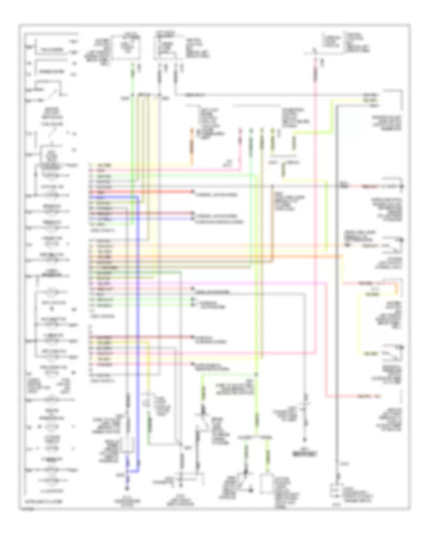
TRANSMISSION
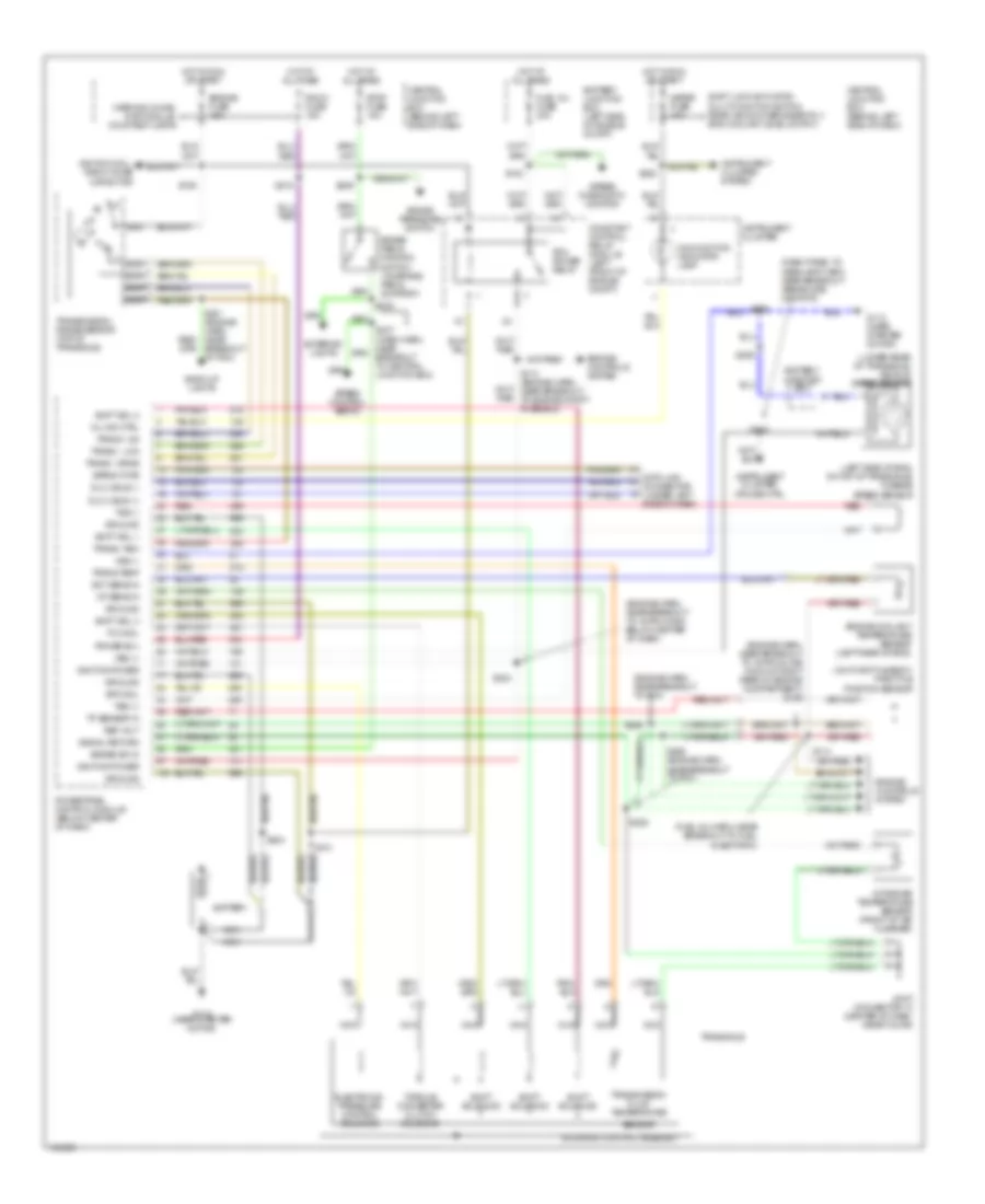
Transmission Wiring Diagram for Mercury Tracer LS 1998
List of elements for Transmission Wiring Diagram for Mercury Tracer LS 1998:
- (dash panel to headlamp harn, near breakout airbag diag monitor)
- (engine harn, near breakout to 16-pin conn below center of dash)
- (engine harn, near breakout to 16-pin inline conn at right rear of engine compartment) s129
- (engine harn, near breakout to pcm)
- (fuel inj harn, near breakout to fuel injector 3)
- (left side of eng, on top of transaxle) turbine speed sensor
- (lower rear of transaxle) vehicle speed sensor
- (on throttle body) throttle position sensor
- Airbag diagnostic monitor
- Back-up lights
- Battery
- Battery junction box
- Battery junction box (left side of engine compt)
- Brake pedal postion switch (on brake pedal support)
- Brake pressure switch
- Brake sw in
- Central junction box (behind left side of dash)
- Constant control relay module (left front of engine compt)
- Data link connector (under left side of dash)
- Dlc 2 bus (+)
- Dlc 2 bus (-)
- Ect sens in
- Electronic pressure control solenoid
- Engine controls system
- Engine coolant temperature sensor (left rear of eng)
- Engine fuse 15a
- Epc sol
- Eprom pwr
- Exterior lights
- Fuel inj fuse 30a
- G112 (near starter motor)
- Ground
- Hot at all times
- Hot in run or start
- Iat sens in
- Ignition coil, radio noise capacitor
- Ignition power
- Instrument cluster
- Instrument cluster system
- Instrument cluster, cruise ctrl
- Intake air temperature sensor (front of air cleaner)
- Joint connector 10 (center of dash, near floor)
- Malfunction indicator lamp
- Meter fuse 10a
- Mil ind ctrl
- Nca
- Pcm power relay
- Power b(+)
- Powertrain control module (below center of dash)
- Red
- Ref volt
- Room fuse 15a
- S101
- S102
- S106
- S113 (engine harn, near breakout to engine compt fuse box)
- S114
- S204
- S205
- S206
- S209
- S218
- S220
- S224
- S225
- S226
- S231 (engine harn, near breakout to pcm)
- S233
- S242
- S266 (engine harn, near breakout to pcm)
- Sensor
- Shift lock actuator, multi-function switch, rear window defogger rly, eng coolant level switch
- Shift sol 1
- Shift sol 2
- Shift sol 3
- Shift solenoid
- Signal return
- Solenoid control assembly
- Speed control servo
- Stop fuse 15a
- Tcc sol
- Torque converter clutch solenoid
- Tp sensor in
- Trans - drive
- Trans - low
- Trans - od
- Trans - rev
- Trans temp
- Transaxle
- Transmission fluid temperature
- Transmission range sensor (top of transaxle)
- Tss (+)
- Tss (-)
- Vss (+)
- Vss (-)
- Warning chime, rap module, courtesy lamps
WARNING SYSTEMS
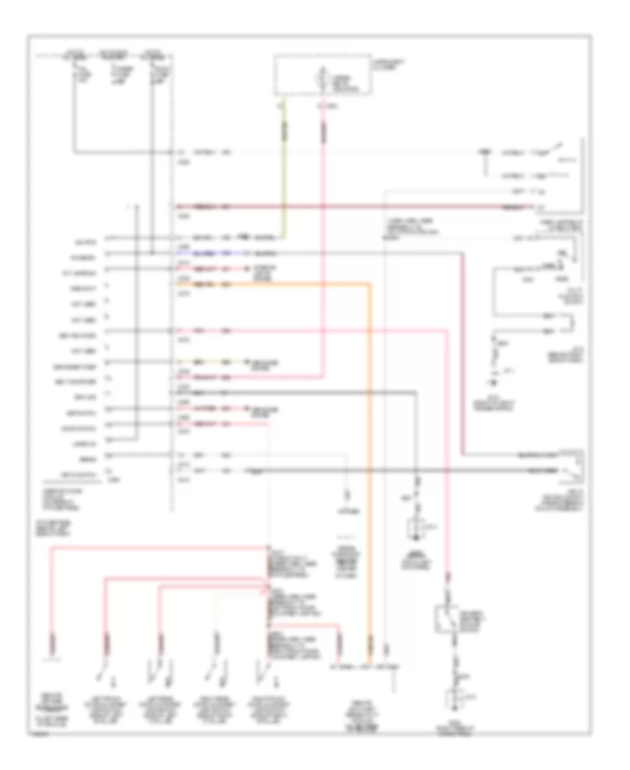
Warning System Wiring Diagrams for Mercury Tracer LS 1998
List of elements for Warning System Wiring Diagrams for Mercury Tracer LS 1998:
- (dash harn, near breakout to multi-function sw) s251
- (in left rear of vehicle)
- Airbag
- Airbag diagnostic monitor (behind center
- Belt buckled
- Belt ind driver
- C210
- C220
- C230
- C232
- C251
- C254
- C260
- C264
- C270
- C290
- C404
- C405
- Def switch
- Defogger system
- Defogger timer
- Door switch
- Driver's seat belt buckle switch
- Fasten belts indicator
- G101 (front of right fender apron)
- G200 (behind top of left kick panel)
- G405 (right rear of cargo area)
- Ground
- Head
- Hot at all times
- Hot in run or start
- I/p fuse panel (behind left side of dash)
- Ign pwr
- Instrument cluster
- Int lamps sig
- Interior lights system
- J/c 1
- J/c 3
- J/c 5 (behind right side of dash)
- J/c 8
- Key in ignition switch (inside steering column assembly)
- Key in switch
- Lamps on
- Left front door courtesy lamp switch (side of left 'b' pillar)
- Left rear door courtesy lamp switch (side of left 'c' pillar)
- Meter fuse 10a
- Multi- function switch
- Nca
- Not used
- Of dash)
- Off
- Park
- Park lamp relay (in relay box)
- Pnk
- Power b+
- Remote anti-theft personality module (in left rear of vehicle)
- Remote keyless entry diode (wagon)
- Right front door courtesy lamp switch (side of right 'b' pillar)
- Right rear door courtesy lamp switch (side of right 'c' pillar)
- Rke input
- Room fuse 10a
- S200
- S201
- S216
- S220
- S303 (rear harn, near breakout to left front door courtesy lamp sw)
- S304 (rear harn, near breakout to right front door courtesy lamp sw)
- S310 (wagon only) (rear harn, near breakout to i/p fuse panel)
- S403
- Tail fuse 15a
- Warning chime module (on rear of i/p fuse panel)
WIPER/WASHER
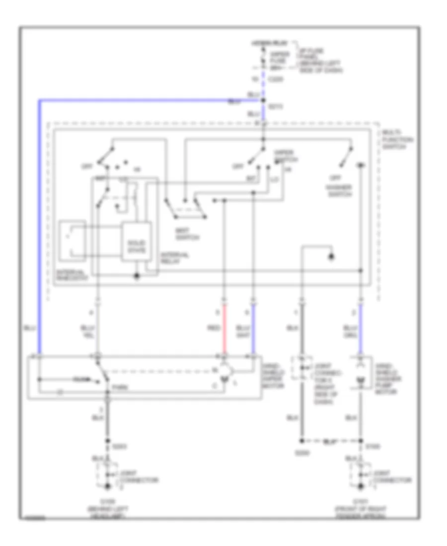
Front Wiper/Washer Wiring Diagram for Mercury Tracer LS 1998
List of elements for Front Wiper/Washer Wiring Diagram for Mercury Tracer LS 1998:
- C220
- G101 (front of right fender apron)
- G106 (behind left headlamp)
- Hot in run
- I/p fuse panel (behind left side of dash)
- Int
- Interval relay
- Interval rheostat
- Joint connec- tor 5 (right side of dash)
- Joint connector
- Mist switch
- Multi- function switch
- Off
- Park
- Red
- Run
- S100
- S200
- S203
- S213
- Solid state
- Washer switch
- Wind- shield washer pump motor
- Wind- shield wiper motor
- Wiper fuse 20a
- Wiper switch
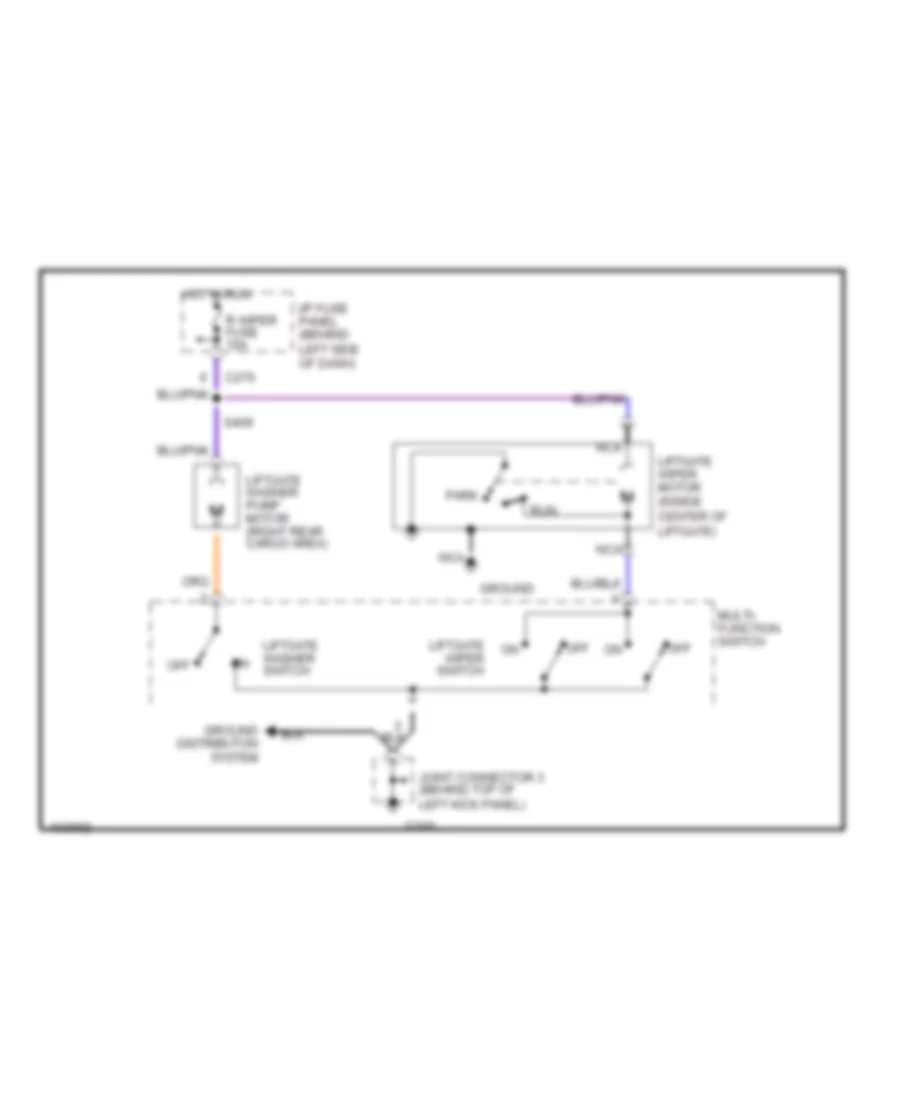
Rear Wiper/Washer Wiring Diagram for Mercury Tracer LS 1998
List of elements for Rear Wiper/Washer Wiring Diagram for Mercury Tracer LS 1998:
- C270
- G200
- Ground
- Ground distributon system
- Hot in run
- I/p fuse panel (behind left side of dash)
- Joint connector 3 (behind top of left kick panel)
- Liftgate washer pump motor (right rear cargo area)
- Liftgate washer switch
- Liftgate wiper motor (inside center of liftgate)
- Liftgate wiper switch
- Multi- function switch
- Nca
- Off
- Park
- R wiper fuse 10a
- Run
- S409