COOLING FAN
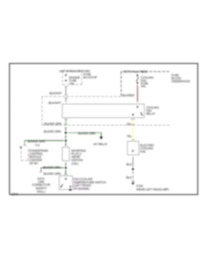
1.8L
1.8L, Cooling Fan Wiring Diagram, A/T for Mercury Tracer LTS 1993

List of elements for 1.8L, Cooling Fan Wiring Diagram, A/T for Mercury Tracer LTS 1993:
- (left front of engine)
- (near left headlamp)
- A/c relay
- Cool- ing fan fuse 40a
- Cooling fan high speed relay (left of air cleaner assembly
- Cooling fan relay
- Data link connector (safety wall)
- Electric cooling fan
- Engine fuse 15a
- Fan coolant temper- ature switch
- Fuse block: underhood
- Fuse block:i/p
- G106
- High fan coolant temperature switch (top left side of radiator)
- Hot at all times
- Hot in run or start
- Powertrain control module (center of i/p)
- Shorting plug 2 (near igntion coil)
1.8L, Cooling Fan Wiring Diagram, M/T for Mercury Tracer LTS 1993
List of elements for 1.8L, Cooling Fan Wiring Diagram, M/T for Mercury Tracer LTS 1993:
- A/c relay
- Cooling fan fuse 30a
- Cooling fan relay
- Data link connector (safety wall)
- Electric cooling fan
- Engine fuse 15a
- Fan coolant temperature switch (left front of engine)
- Fuse block: underhood
- Fuse block:i/p
- G106 (near left headlamp)
- Hot at all times
- Hot in run or start
- Powertrain control module (center of i/p)
- Shorting plug 2 (near igntion coil)
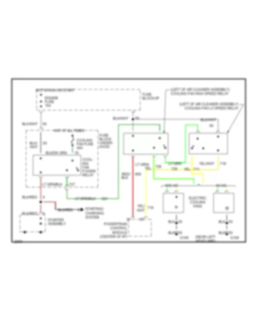
1.9L
1.9L, Cooling Fan Wiring Diagram for Mercury Tracer LTS 1993
List of elements for 1.9L, Cooling Fan Wiring Diagram for Mercury Tracer LTS 1993:
- (left of air cleaner assembly) cooling fan high speed relay
- (left of air cleaner assembly) cooling fan lo speed relay
- (near left headlamp)
- Cool- ing fan power relay
- Cooling fan fuse 40a
- Electric cooling fans
- Engine fuse 15a
- Fuse block: under- hood
- Fuse block:i/p
- G106
- Hot at all times
- Hot in run or start
- Powertrain control module (center of i/p)
- Starter assembly
- Starting/ charging system
- W/ a/c
- W/o a/c
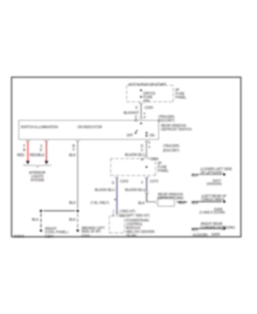
DEFOGGERS
Defogger Wiring Diagram for Mercury Tracer LTS 1993
List of elements for Defogger Wiring Diagram for Mercury Tracer LTS 1993:
- (1.8l only)
- (1993 a/t) (except 1993 a/t)
- (3 and 5 door)
- (4 door)
- (behind left side of i/p) g202
- (right cowl panel) g201
- (tracer) (escort)
- (wagon)
- A e
- B f
- C210
- C260
- C270
- D c
- Defog fuse 20a
- F b
- G405
- G406
- G411
- Hot in run or start
- I/p fuse panel
- Interior lights system
- Off
- On indicator
- Powertrain control module (below center of i/p)
- Rear window defrost grid
- Rear window defrost switch
- Red
- Switch illumination
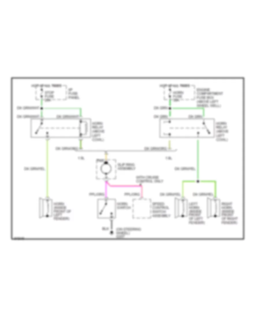
HORN
Horn Wiring Diagram for Mercury Tracer LTS 1993
List of elements for Horn Wiring Diagram for Mercury Tracer LTS 1993:
-
- (on steering wheel) g207
- 1.8l
- 1.9l
- Engine compartment fuse box (above left wheel well)
- Horn (inside front of left fender)
- Horn fuse 30a
- Horn relay (above left cowl)
- Horn switch
- Hot at all times
- I/p fuse panel
- Left horn (inside front of left fender)
- Right horn (inside front of right fender)
- Slip ring assembly
- Speed control switch assembly
- Stop fuse 20a
- Tan
- With cruise control only
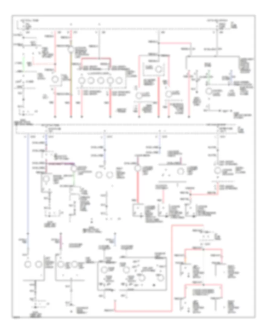
INTERIOR LIGHTS
Interior Light Wiring Diagram for Mercury Tracer LTS 1993
List of elements for Interior Light Wiring Diagram for Mercury Tracer LTS 1993:
- meter fuse
- (am/fm stereo) (premiun sound)
- (behind top of left cowl panel)
- (near left headlamp)
- (sport) (standard)
- (standard) (sport)
- * **
- * escort ** tracer
- 1.8l only
- 15a
- 3 & 5 door hatchback
- 3 & 5 door hatchback & wagon
- 4 door sedan
- 5 door hatchback 4 door notchback & wagon only
- A/c heater control assembly
- Automatic transaxle selector illumination lamp
- C b
- C210
- C232
- C249
- C249 c254
- C250 c252
- C251
- C252
- C270
- Control illumi- nation
- Dome lamp
- Dome lamp assembly
- Dome lamp switch
- Dome/map lamp assembly
- Door
- E a
- E e
- Electronic radio (w/o cd player)
- Electronic radio/cd player (w/ cd player)
- Engine compart- ment lamp
- F b
- F f
- Fog lamp switch
- G106
- G200
- G201 (right side of dash)
- G206 (behind center of dash)
- H d
- Head
- Hot at all times
- Hot in acc or run
- Hot in run or start
- I/p fuse panel
- Ignition switch illumination lamp
- Illumi- nation
- Illumination lamps
- Instru- ment cluster
- Instrument panel dimming module (left of steering column)
- J/c
- J/c behind top left of dash)
- Lcd illumi- nation
- Left
- Left front door courtesy lamp switch
- Left illu- minated vanity mirror
- Left map lamp
- Left rear door courtesy lamp switch
- Liftgate ajar indicator
- Liftgate latch switch (in center rear of cargo area)
- Liftgate latch switch (in center rear of liftgate)
- Luggage compart- ment lamp
- Luggage compart- ment switch (right front of trunk, near hinge support)
- Main light switch
- Map lamp assembly
- Map lamp switches
- Moonroof drive assembly
- Nca
- Off
- Park
- Park lamp relay (left side of dash)
- Radio fuse 15a
- Rear window defrost switch
- Red
- Right
- Right front door courtesy lamp switch
- Right illu- minated vanity mirror
- Right map lamp
- Right rear door courtesy lamp switch
- Room fuse
- Solid state
- Tail fuse 15a
- W/ power moonroof
- W/o power moonroof
- Wagons
- Warning chime module (on rear of i/p fuse panel)
- With power moonroof
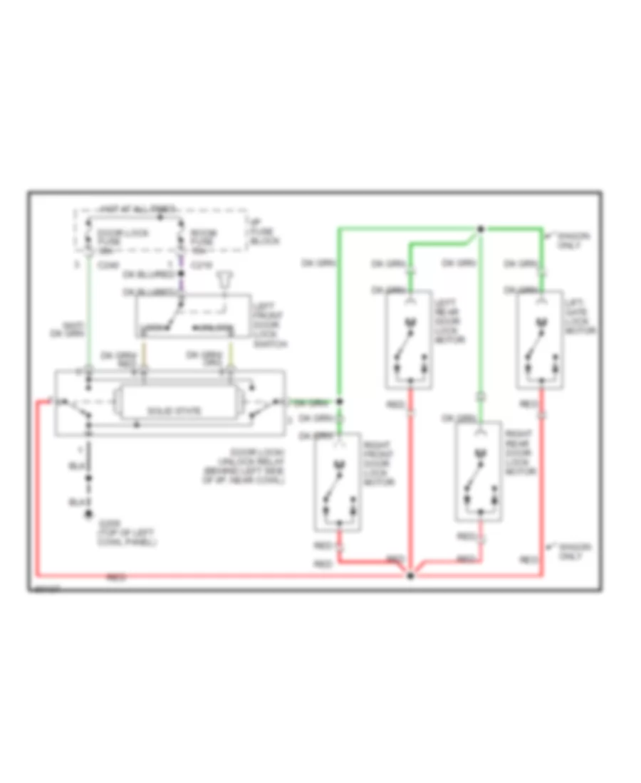
POWER DOOR LOCKS
Power Door Lock Wiring Diagram for Mercury Tracer LTS 1993
List of elements for Power Door Lock Wiring Diagram for Mercury Tracer LTS 1993:
- C210
- C240
- Door lock fuse 30a
- Door lock/ unlock relay (behind left side of i/p, near cowl)
- G200 (top of left cowl panel)
- Hot at all times
- I/p fuse block
- Left front door lock switch
- Left rear door lock motor
- Lift- gate lock motor
- Lock
- Red
- Right front door lock motor
- Right rear door lock motor
- Room fuse 15a
- Solid state
- Unlock
- Wagon only
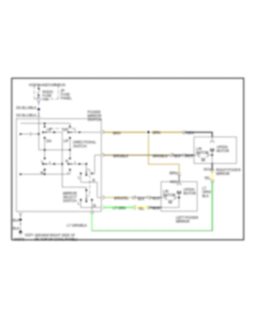
POWER MIRRORS
Power Mirror Wiring Diagram for Mercury Tracer LTS 1993
List of elements for Power Mirror Wiring Diagram for Mercury Tracer LTS 1993:
- (behind right side of i/p, top of cowl panel)
- Directional switch
- G201
- Hot in accy or run
- I/p fuse panel
- L/r motor
- Left power mirror
- Mirror select switch
- Nca
- Power mirror switch
- Radio fuse 15a
- Right power mirror
- Up/dn motor
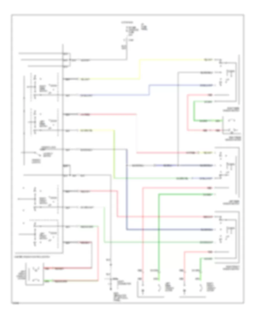
POWER WINDOWS
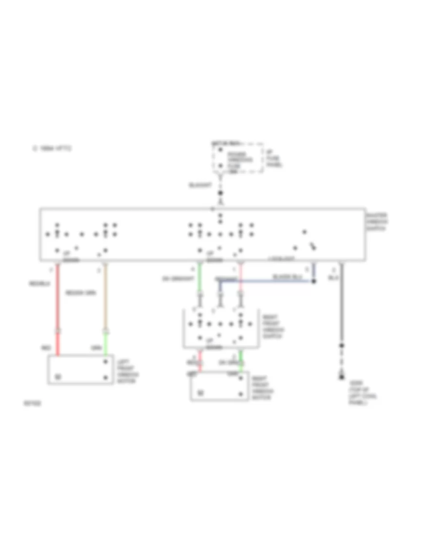
Power Window Wiring Diagram for Mercury Tracer LTS 1993
List of elements for Power Window Wiring Diagram for Mercury Tracer LTS 1993:
- C224
- C240
- Down
- G200 (behind top of left cowl panel)
- Hot in run
- I/p fuse panel
- Joint connector
- Left front switch
- Left front window motor
- Left rear switch
- Left rear window motor
- Left rear window switch
- Lockout switch
- Master window control switch
- Power windows fuse 30a
- Red
- Right front switch
- Right front window motor
- Right front window switch
- Right rear switch
- Right rear window motor
- Right rear window switch
- Window lock off
- Window lock on
Power Window Wiring Diagram, Hatchback for Mercury Tracer LTS 1993
List of elements for Power Window Wiring Diagram, Hatchback for Mercury Tracer LTS 1993:
- 1994 vftc c
- G200 (top of left cowl panel)
- Hot in run
- I/p fuse panel
- Left front window motor
- Lock-out
- Master window switch
- Power windows fuse 30a
- Red
- Right front window motor
- Right front window switch
- Up down
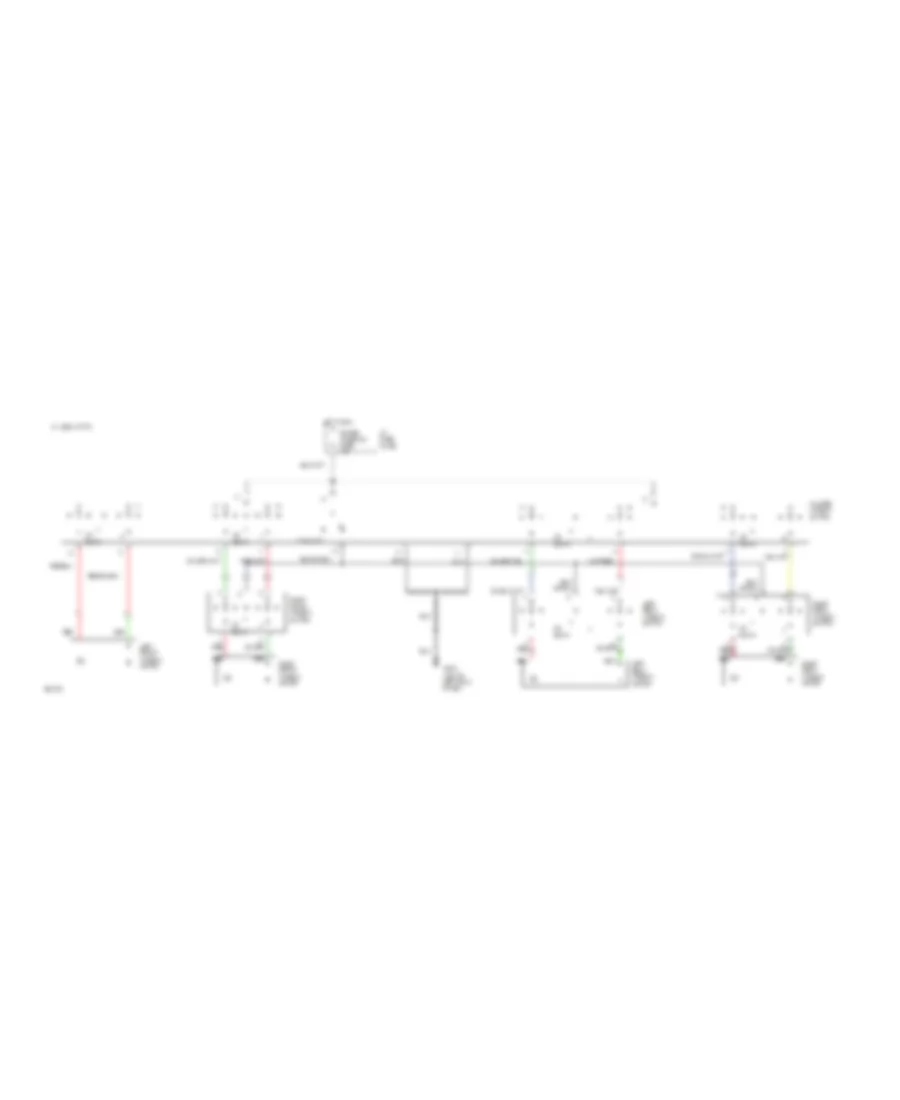
Power Window Wiring Diagram, Sedan & Wagon for Mercury Tracer LTS 1993
List of elements for Power Window Wiring Diagram, Sedan & Wagon for Mercury Tracer LTS 1993:
- 1994 vftc c
- G200 (top of left cowl panel)
- Hot in run
- I/p fuse panel
- Left front window motor
- Left rear window motor
- Left rear window switch
- Lock-out
- Master window switch
- Power windows fuse 30a
- Red
- Right front window motor
- Right rear window motor
- Right front window switch
- Right rear window switch
- Up down
RADIO
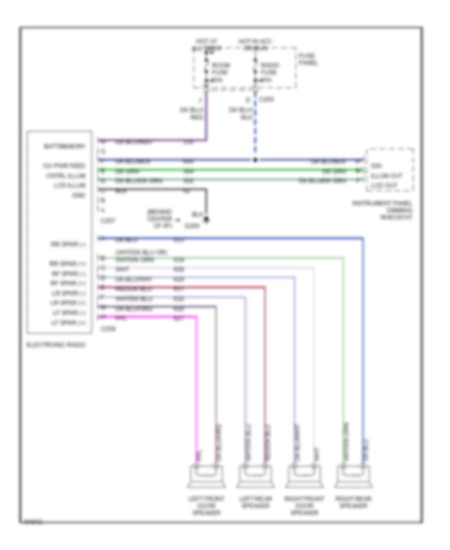
Radio Wiring Diagrams, Base Radio for Mercury Tracer LTS 1993
List of elements for Radio Wiring Diagrams, Base Radio for Mercury Tracer LTS 1993:
- (behind center of i/p)
- 12v pwr feed
- Batt/memory
- C257
- C258
- C260
- Cntrl illum
- Electronic radio
- Fuse panel
- G206
- Gnd
- Hot at all times
- Hot in acc or run
- Ign
- Illum out
- Instrument panel dimming rheostat
- Lcd illum
- Lcd out
- Left front door speaker
- Left rear speaker
- Lf spkr (+)
- Lf spkr (-)
- Lr spkr (+)
- Lr spkr (-)
- Radio fuse 15a
- Rf spkr (+)
- Rf spkr (-)
- Right front door speaker
- Right rear speaker
- Room fuse 10a
- Rr spkr (+)
- Rr spkr (-)
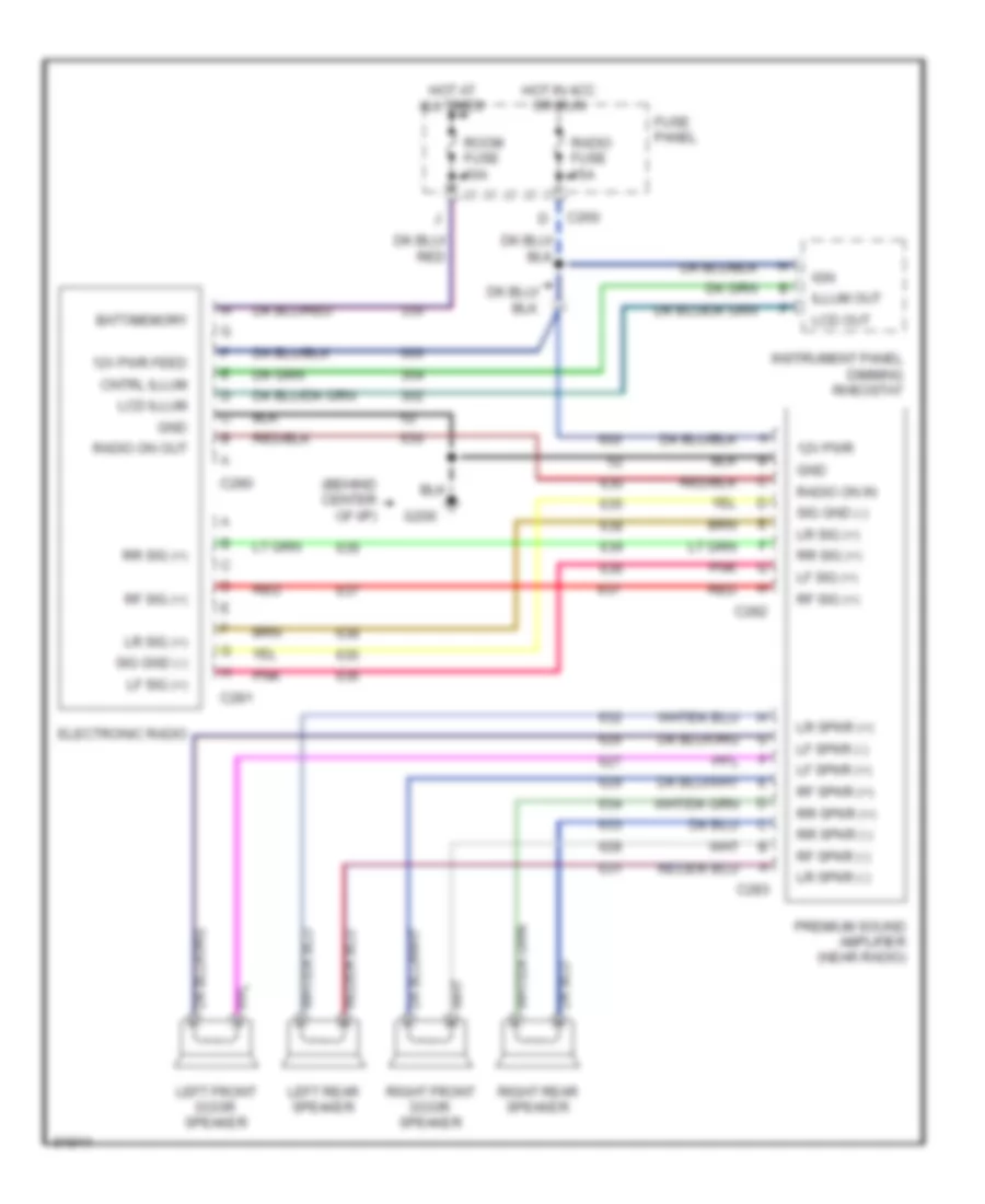
Radio Wiring Diagrams, Premium Radio for Mercury Tracer LTS 1993
List of elements for Radio Wiring Diagrams, Premium Radio for Mercury Tracer LTS 1993:
- (behind center of i/p)
- 12v pwr
- 12v pwr feed
- Batt/memory
- C260
- C280
- C281
- C282
- C283
- Cntrl illum
- Electronic radio
- Fuse panel
- G206
- Gnd
- Hot at all times
- Hot in acc or run
- Ign
- Illum out
- Instrument panel dimming rheostat
- Lcd illum
- Lcd out
- Left front door speaker
- Left rear speaker
- Lf sig (+)
- Lf spkr (+)
- Lf spkr (-)
- Lr sig (+)
- Lr spkr (+)
- Lr spkr (-)
- Pnk
- Premium sound amplifier (near radio)
- Radio fuse 15a
- Radio on in
- Radio on out
- Red
- Rf sig (+)
- Rf spkr (+)
- Rf spkr (-)
- Right front door speaker
- Right rear speaker
- Room fuse 10a
- Rr sig (+)
- Rr spkr (+)
- Rr spkr (-)
- Sig gnd (-)
STARTING/CHARGING
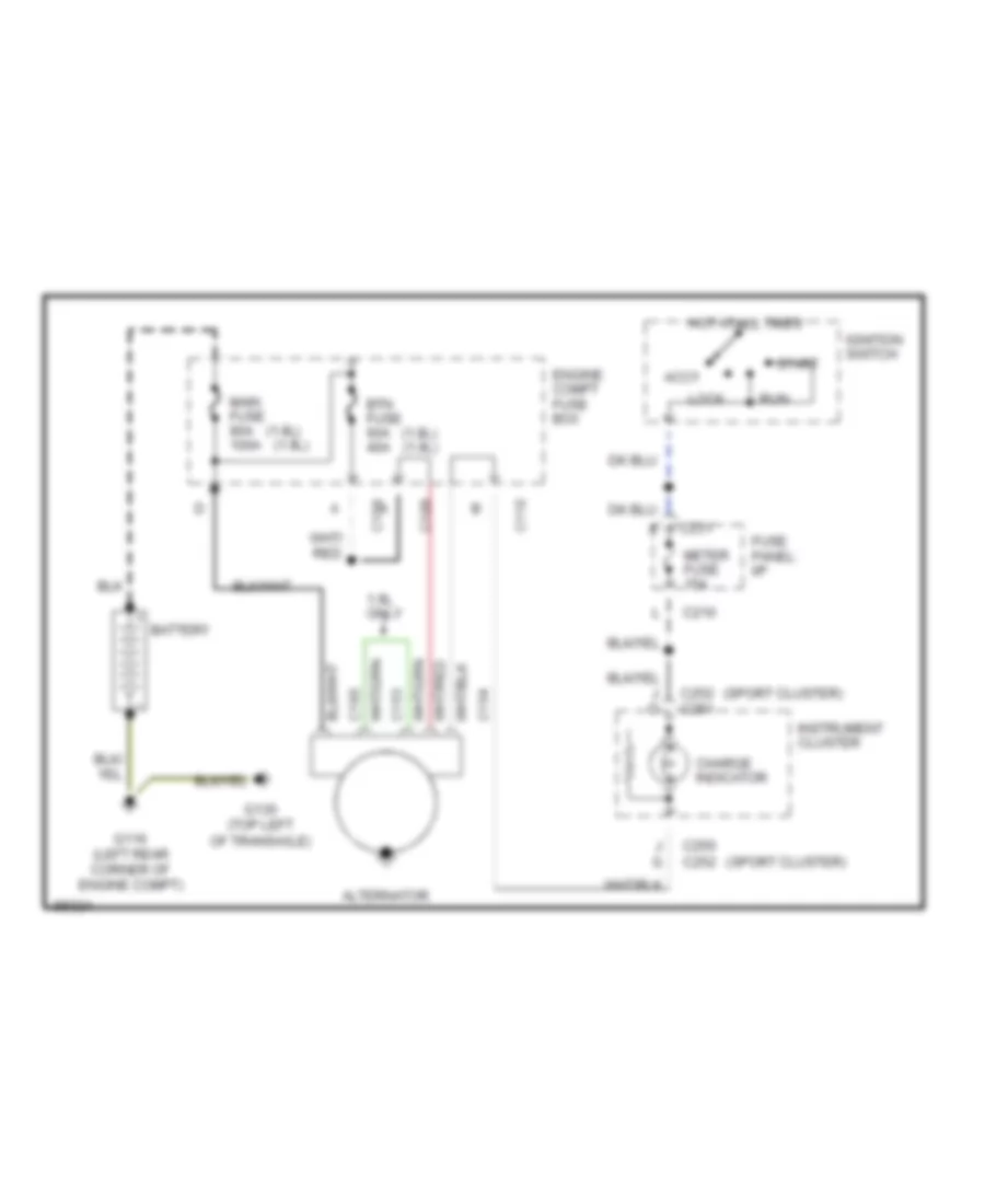
Charging Wiring Diagram for Mercury Tracer LTS 1993
List of elements for Charging Wiring Diagram for Mercury Tracer LTS 1993:
- (1.8l) (1.9l)
- (sport cluster)
- 1.9l only
- Accy
- Alternator
- Battery
- Btn fuse 60a 40a
- C108
- C109
- C110
- C153
- C154
- C160
- C210
- C231
- C250 c252
- C252 c251
- Charge indicator
- Engine compt fuse box
- Fuse panel: i/p
- G116 (left rear corner of engine compt)
- G130 (top left of transaxle)
- Hot at all times
- Ignition switch
- Instrument cluster
- J g
- Lock
- Main fuse 80a 100a
- Meter fuse 15a
- Run
- Start
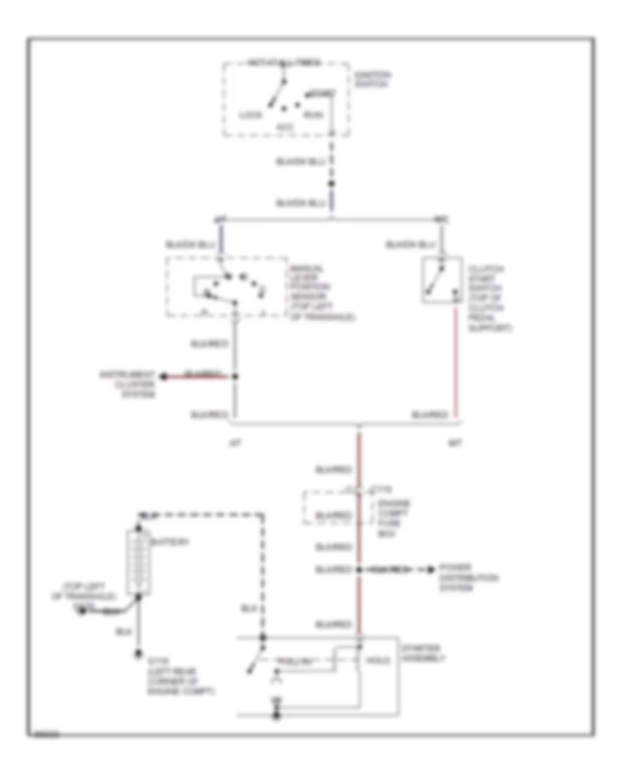
Starting Wiring Diagram for Mercury Tracer LTS 1993
List of elements for Starting Wiring Diagram for Mercury Tracer LTS 1993:
- (top left of transaxle) g130
- A/t
- Acc
- Battery
- C110
- Clutch start switch (top of clutch pedal support)
- Engine compt fuse box
- G116 (left rear corner of engine compt)
- Hold
- Hot at all times
- Ignition switch
- Instrument cluster system
- Lock
- M/t
- Manual lever position sensor (top left of transaxle)
- Power distribution system
- Pull-in
- Run
- Start
- Starter assembly
TRANSMISSION
1.8L
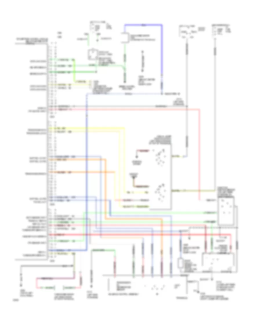
1.8L, Transmission Wiring Diagram for Mercury Tracer LTS 1993
List of elements for 1.8L, Transmission Wiring Diagram for Mercury Tracer LTS 1993:
- (1993)
- (1994)
- (behind center of i/p, near floor)
- (ect) sensor input
- (iat) sensor input
- (left front of engine compt, under air cleaner)
- (left rear corner of engine compt, on safety wall)
- (left side
- (lower left rear of engine compt,
- (partial)
- (top of left
- (tp) sensor input
- (tp) switch input
- Acc
- Backup lamps
- Brake on/off in
- Brake on/off switch (on brake pedal support)
- C204
- C205
- C238
- Cleaner)
- Cowl panel)
- Data link conn
- Data link connector
- Engine coolant temperature sensor (top left side of engine)
- G100
- G110
- G116
- G200
- G206
- Hot at all times
- Hot in start or run
- I/p fuse panel
- Ignition switch
- Lock
- Lock up
- Manual lever position switch (left side of engine, on top of transaxle)
- Meter fuse 15a
- Nca
- Of engine)
- On safety wall)
- Powertrain control module (below center of i/p)
- Red
- Red b
- Ref volt out
- Run
- Shft sol out #1
- Shft sol out #2
- Shft sol out #3
- Solenoid control assembly
- Speed control amplifier
- Start
- Start in
- Starting system
- Stop fuse 20a
- Stop lamp switch
- Tcc sol out
- Throttle position sensor (top left rear of engine, on throttle body)
- Trans oil temp in
- Trans rnge-drive in
- Trans rnge-low in
- Trans rnge-od in
- Transaxle
- Transmission oil temperature sensor
- Turbine spd sens in (+)
- Turbine spd sens in (-)
- Turbine speed sensor (left side of engine, on top of transaxle)
- Vane air flow meter (on air
- Vane air flow meter in
- Veh spd sens in
- Vehicle speed sensor (vss) (lower rear of transaxle)
- Vss in (-)
1.9L
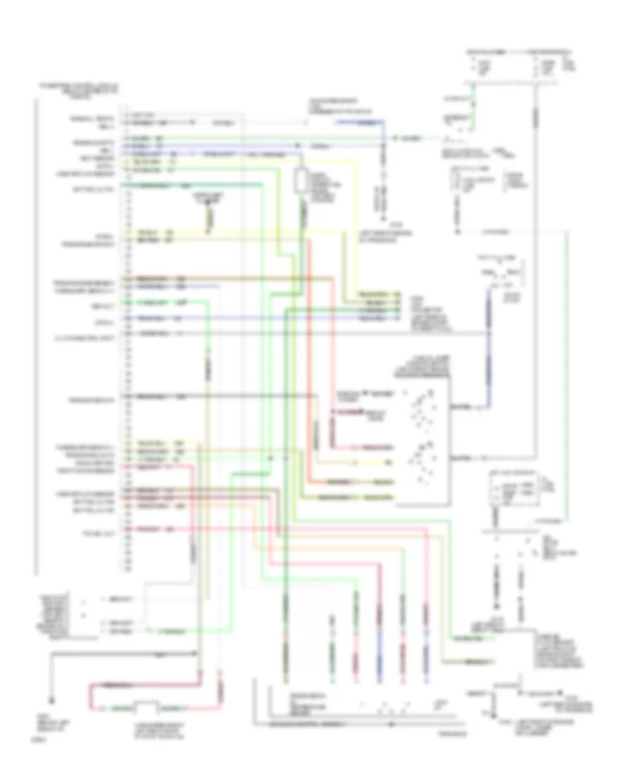
1.9L, Transmission Wiring Diagram for Mercury Tracer LTS 1993
List of elements for 1.9L, Transmission Wiring Diagram for Mercury Tracer LTS 1993:
- (1993)
- (1994)
- (behind left
- (ect) sensor
- (left front of engine compt, under air cleaner)
- (left rear of engine compt, on safety wall)
- (left side of engine,
- (left side of engine, on transaxle)
- (left side of safety wall)
- (partial)
- Acc
- Backup lamps
- Brake on/off in
- Clutch/neutral input
- Data (+)
- Data (-)
- Data link connector
- Engine
- Engine compt fuse box
- Engine coolant temperature sensor (left rear of engine)
- Fuel injector fuse 30a
- G100
- G116
- G130
- G202
- Hot at all times
- Hot in run or start
- Hot in start or run
- I/p fuse panel
- Ignition switch
- Instrument cluster
- Lock
- Lock up
- Manual lever position switch (left side of engine, on top of transaxle)
- Mass air flow sensor
- Mass air flow sensor (left front of engine compt, on right side of air cleaner assy)
- Meter fuse 15a
- Nca
- On transaxle)
- Pcm power relay (below center of i/p)
- Powertrain control module (below center of i/p)
- Ref volt
- Run
- Shft sol out #1
- Shft sol out #2
- Shft sol out #3
- Side of i/p)
- Signal return
- Solenoid control assembly
- Start
- Starting system
- Sto/mil
- Stop fuse 20a
- Stop lamp switch brake on/off switch
- Tcc sol out
- Throttle pos sensor
- Throttle position sensor (top left rear of engine, on throttle body)
- Trans oil temp in
- Trans rnge-drive in
- Trans rnge-low in
- Trans rnge-od in
- Trans rnge-reverse in
- Transaxle
- Transmission oil temperature sensor
- Turbine spd sens in (+)
- Turbine spd sens in (-)
- Turbine speed sensor (left side of engine, on top of transaxle)
- Vehicle speed sensor (vss) (lower rear of transaxle)
- Vss (+)
- Vss (-)
WIPER/WASHER
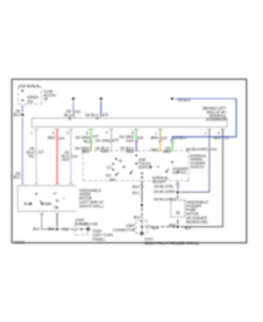
Interval Wiper/Washer Wiring Diagram for Mercury Tracer LTS 1993
List of elements for Interval Wiper/Washer Wiring Diagram for Mercury Tracer LTS 1993:
- (behind left side of i/p) interval governor
- Fuse block: i/p
- G101 (right front fender apron)
- G200 (left cowl panel)
- Hot in run
- Int
- Interval adjust
- Interval wiper/ washer switch
- Joint connector
- Off
- One touch switch
- Park
- Red
- Run
- Washer switch
- Windshield washer pump motor (in washer reservoir)
- Windshield wiper motor (left side of safety wall)
- Wiper 20a
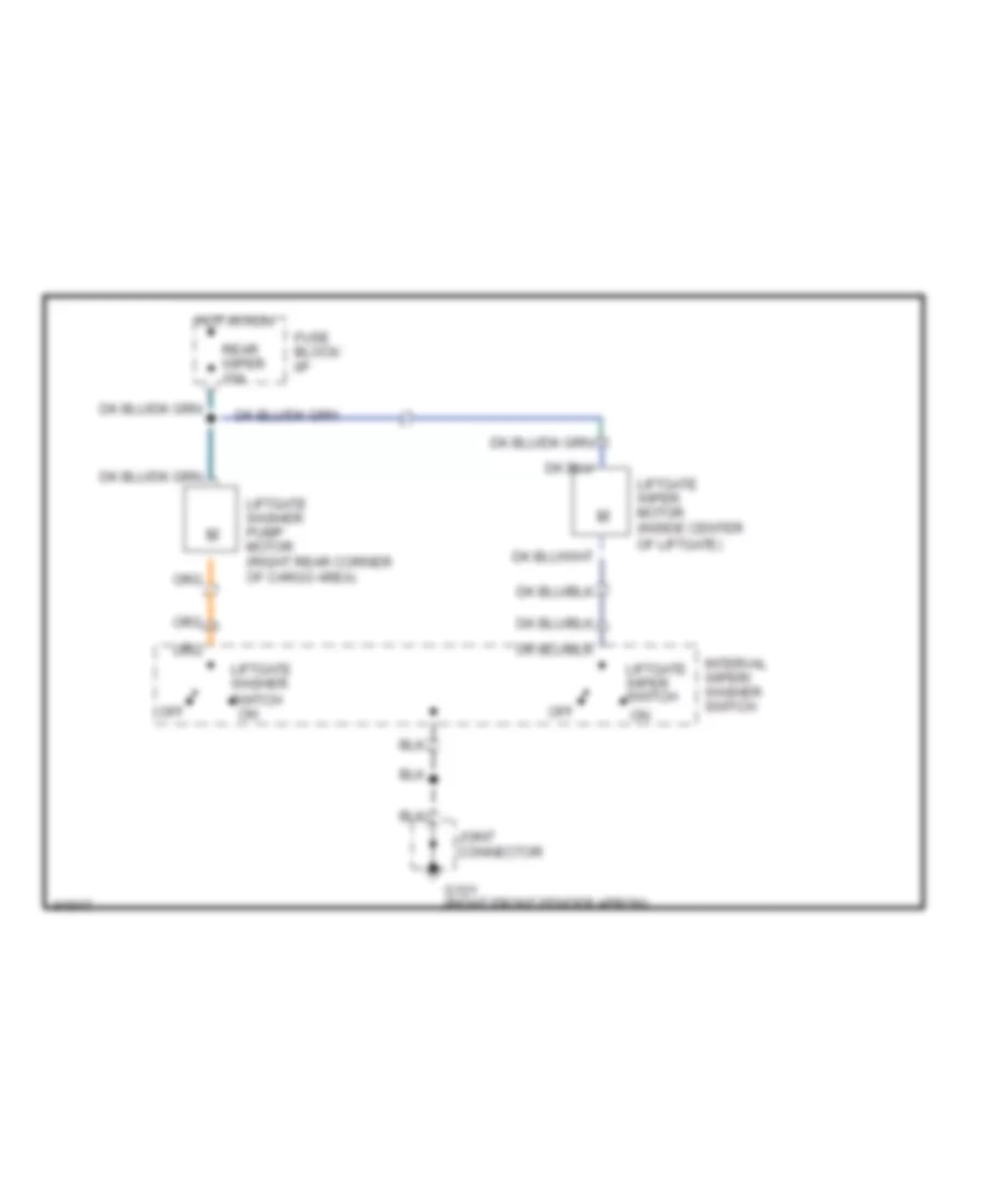
Rear Wiper/Washer Wiring Diagram for Mercury Tracer LTS 1993
List of elements for Rear Wiper/Washer Wiring Diagram for Mercury Tracer LTS 1993:
- Fuse block: i/p
- G101 (right front fender apron)
- Hot in run
- Interval wiper/ washer switch
- Joint connector
- Liftgate washer pump motor (right rear corner of cargo area)
- Liftgate washer switch on
- Liftgate wiper motor (inside center of liftgate)
- Liftgate wiper switch
- Off
- Rear wiper 10a