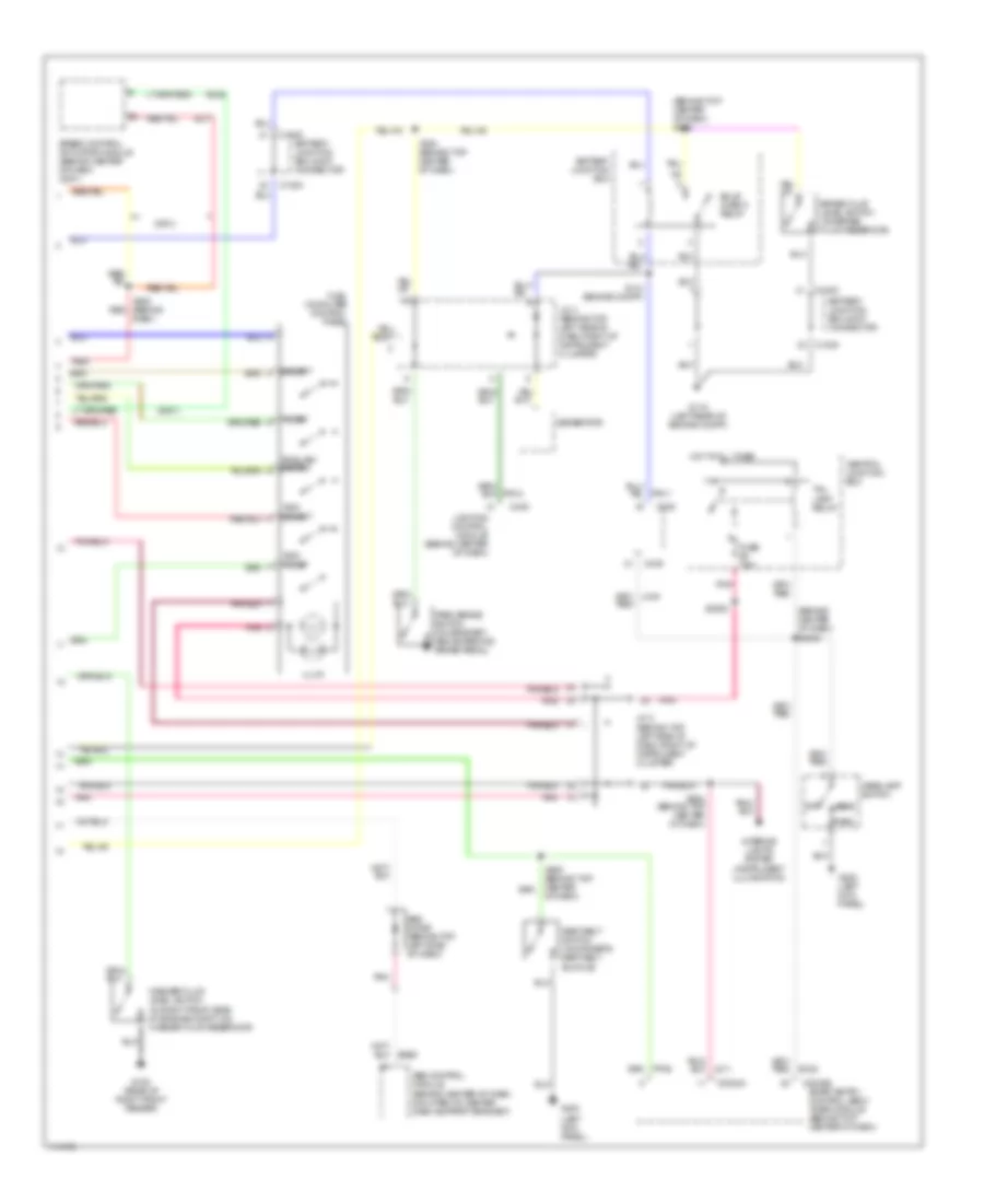
AIR CONDITIONING
Automatic A/C Wiring Diagram (1 of 2) for Mercury Villager Estate 2001

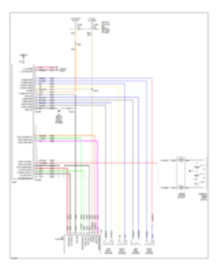
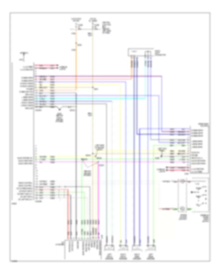
List of elements for Automatic A/C Wiring Diagram (1 of 2) for Mercury Villager Estate 2001:
- (behind center of dash) s288
- (behind right side of dash) g201
- (behind top center of dash) s237
- (behind top center of dash) s249
- Acc
- Ambient air temperature sensor (on front center of engine compartment)
- Battery junction box (on left front of engine compartment)
- C2016
- C202
- C2028a
- C2028b
- C204
- C218
- C369a
- C369b
- Central junction box (behind left side of dash)
- Central junction box (behind left side of dash)
- Coolant temperature sensor 1 (on top center rear of engine)
- Electronic automatic temperature control (eatc) module (behind center of dash)
- Fresh/recirculation door actuator (behind right side of dash, on a/c-heater plenum)
- Front blend door actuator (behind right center of dash, on a/c-heater plenum)
- Front blower motor (behind right side of dash, on a/c-heater plenum)
- Front blower motor relay
- Front blower motor speed controller (behind right side of dash)
- Fuse 10a
- Fuse 20a
- Fuse 65a
- Fuse 7.5a
- Ha01
- Ha02
- Ha04
- Ha06
- Ha09
- Ha11
- Ha12
- Ha13
- Ha14
- Ha15
- Ha16
- Ha17
- Ha18
- Ha20
- Ha21
- Ha22
- Ha23
- Ha24
- Ha28
- Hae2
- Hb22
- Hc02
- Hc03
- Hc04
- Hc05
- Hc06
- Hc14
- Hc15
- Hc16
- Hc17
- Hc23
- Hce1
- Hce2
- Hho1
- Hot at all times
- Hot in run
- Hot in run or start
- If equipped w/electronic instrument cluster
- Ignition switch
- Ih01
- Ih91
- Illumination
- In-vehicle temperature sensor (behind center of dash)
- Instrument cluster system
- Interior lights system
- Nca
- Off
- Pnk
- Rear a/c circuit
- Run
- S2015 (behind center of dash)
- S231 (behind top center of dash)
- S236 (behind right side of dash)
- Solid state
- Start
- Sunload sensor (on top left side of dash)
- Villager
Automatic A/C Wiring Diagram (2 of 2) for Mercury Villager Estate 2001
List of elements for Automatic A/C Wiring Diagram (2 of 2) for Mercury Villager Estate 2001:
- (behind right side of dash) g201
- (front of engine compartment) s116
- (left front side of engine compartment) s158
- (left front side of engine compartment) s159
- (left rear side of engine compartment) g104
- (right front side of engine compartment) s1003
- (right front side of engine compartment) s1004
- (top left side of engine compartment) s1001
- (top of engine) g134
- A/c clutch solenoid (on right front side of engine compartment)
- A/c compressor clutch diode (on right front of engine compartment)
- A/c compressor cycling switch (1: pressure increasing) (2: pressure decreasing) (on right side of engine compartment)
- A/c relay
- Aw16
- Aw17
- Battery junction box (bjb) joint connector
- Battery junction box (on left front of engine compartment)
- C1000
- Dual pressure switch (in right front of engine compartment)
- Engine compartment relay box (on left front of engine compartment)
- Engine cooling fan motor (behind radiator)
- Fa06
- Fa12
- Fuse 20a
- Fuse 7.5a
- Fuse 75a
- Ha41
- Ha45
- High
- High speed fan control relay 1
- High speed fan control relay 2
- Hot at all times
- Hx01
- Idle speed control (on top rear center of engine)
- Low speed fan control relay
- Mode actuator (behind center of dash)
- Normal
- Powertrain control module (pcm) (behind right side of dash, behind glove box)
- Solid state
- Villager
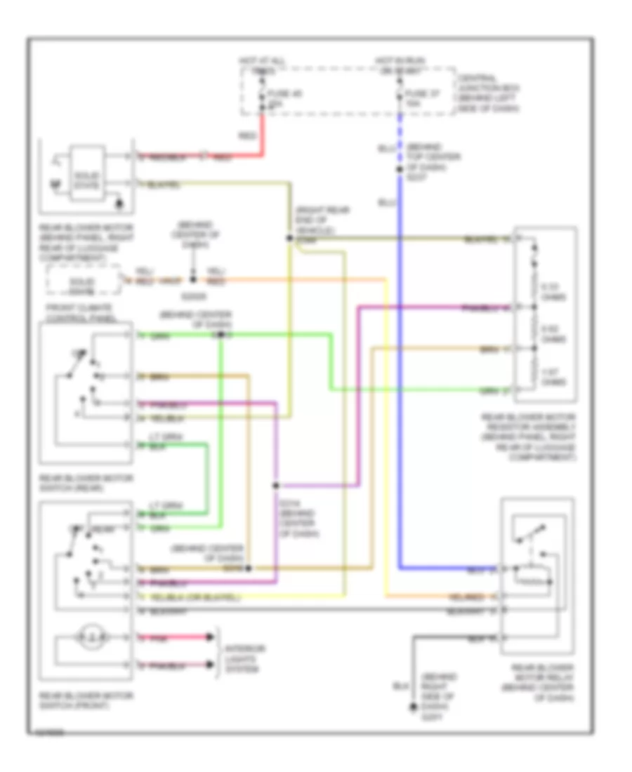
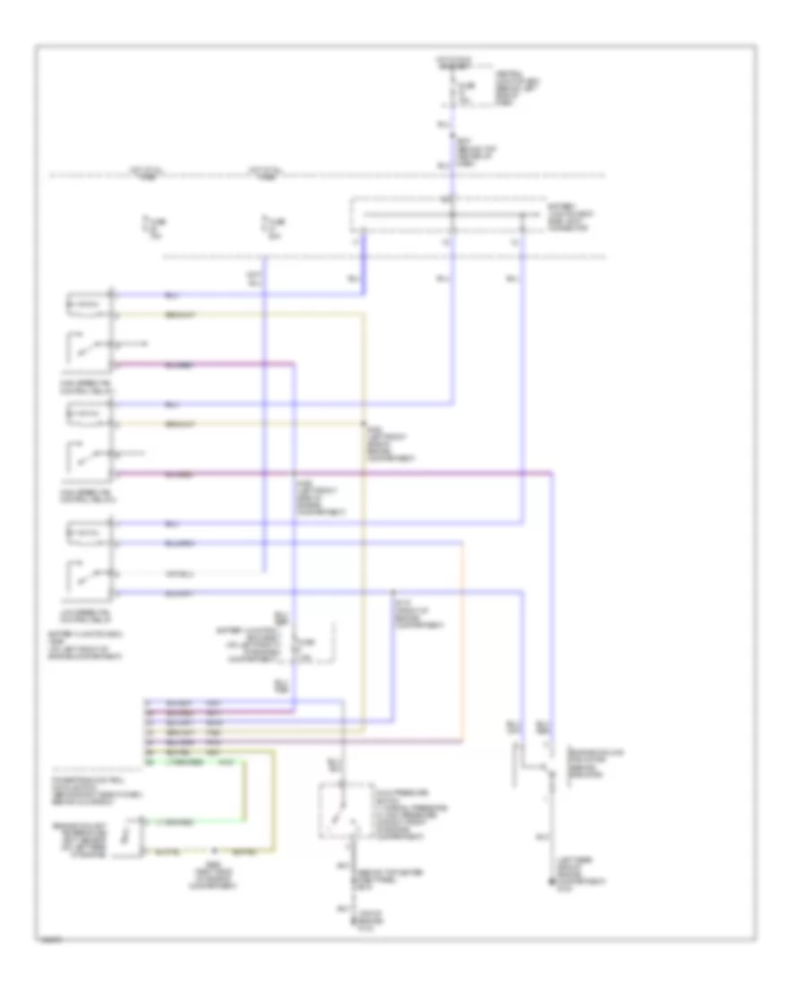
Automatic A/C Wiring Diagram, Rear A/C for Mercury Villager Estate 2001
List of elements for Automatic A/C Wiring Diagram, Rear A/C for Mercury Villager Estate 2001:
- (behind center of dash) s313
- (behind center of dash) s318
- (under left side of dash) g202
- 0.33 ohms
- 0.62 ohms
- 1.67 ohms
- C2028a
- Central junction box (behind left side of dash)
- Electronic automatic temperature control module (behind center of dash)
- Fuse 37 10a
- Fuse 45 15a
- Hb22
- Hot at all times
- Hot in run or start
- Interior lights system
- Off
- Pnk
- Rear
- Rear blower motor (behind panel, right rear side of luggage compartment)
- Rear blower motor relay (behind center of dash)
- Rear blower motor resistor assembly (behind panel, right rear of luggage compartment)
- Rear blower motor switch (front)
- Rear blower motor switch (rear)
- Red
- S314 (behind center of dash)
- S344 (right rear end of vehicle)
- Solid state
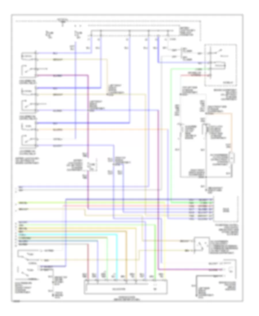
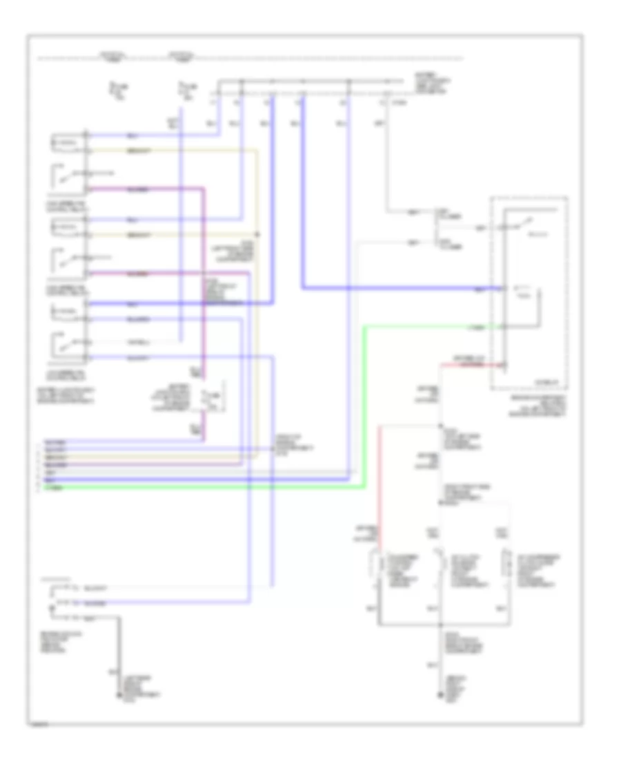
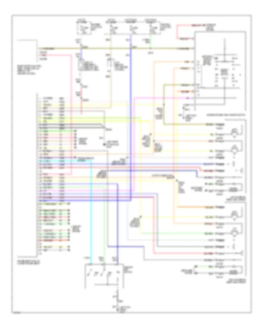
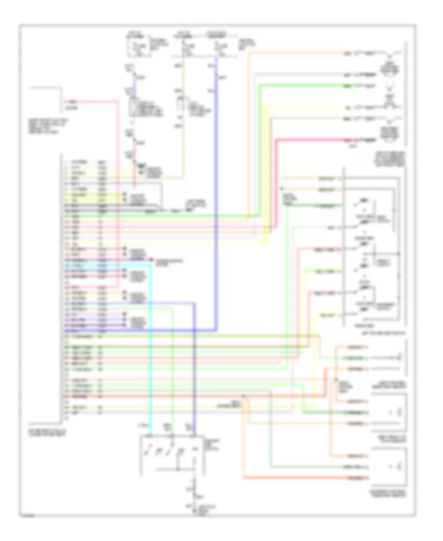
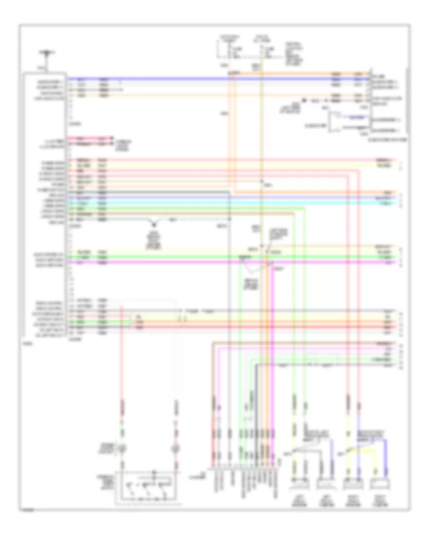
Manual A/C Wiring Diagram (1 of 2) for Mercury Villager Estate 2001
List of elements for Manual A/C Wiring Diagram (1 of 2) for Mercury Villager Estate 2001:
- (behind center of dash) s2050
- (behind center of dash) s2051
- (behind left side of dash) s2100
- (behind right side of dash) g201
- (behind right side of dash) s236
- (behind top center of dash) s237
- (behind top center of dash) s287
- (top of engine) g134
- (under left side of dash) g202
- 0.33 ohms
- 0.62 ohms
- 1.67 ohms
- A/c compressor cycling switch (1: pressure increasing) (2: pressure decreasing) (on right side of engine compartment)
- Acc
- Aw16
- Aw17
- Battery junction box (on left front of engine compartment)
- C2016
- C202
- C204
- C218
- Center of dash) s219
- Central junction box (behind left side of dash)
- Dual pressure switch (in right front of engine compartment)
- Fa06
- Fa12
- Fresh/recirculation door actuator (behind right side of dash, on a/c heater
- Front blend door actuator (behind right center of dash, on a/c heater plenum)
- Front blower motor (behind right side of dash, on a/c heater plenum)
- Front blower motor relay
- Front blower motor resistor assembly (behind right side of dash, in a/c heater plenum)
- Front blower motor switch
- Front climate control panel
- Fuse 10a
- Fuse 33 20a
- Fuse 39 20a
- Fuse 65a
- Fuse 7.5a
- Ha01
- Ha02
- Ha05
- Ha06
- Ha09
- Ha11
- Ha41
- Ha45
- Hae2
- High
- Hot at all times
- Hot in run
- Hot in run or start
- Hx01
- If equipped
- Ignition switch
- Ih91
- Iho1
- Illum
- Interior lights system
- Left side of dash) s250
- Low
- Med high
- Med low
- Mode actuator (behind center of dash)
- Normal
- Of dash) s2027
- Off
- Plenum)
- Pnk
- Powertrain control module (pcm) (behind right side of dash, behind glove box)
- Rear a/c circuit
- Run
- S248 (behind top center of dash)
- Solid state
- Start
- Temperature door variable resistor (behind center of dash)
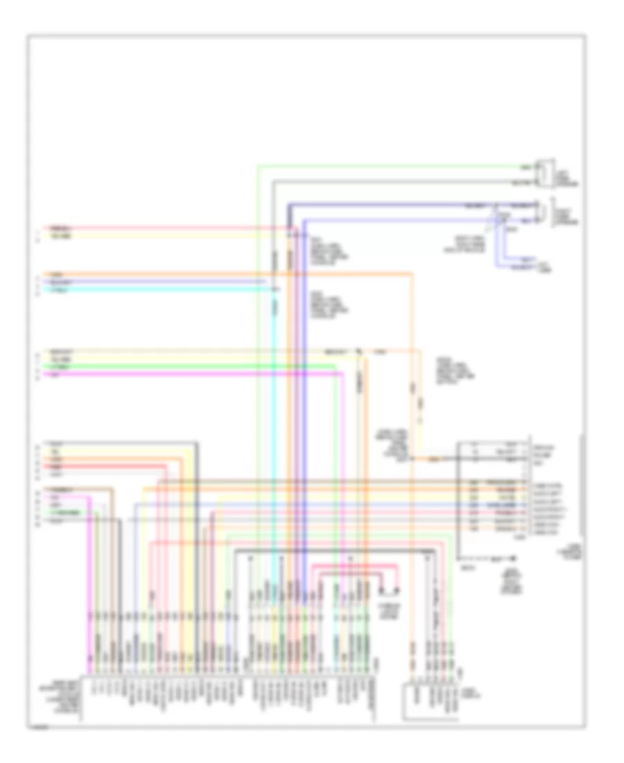
Manual A/C Wiring Diagram (2 of 2) for Mercury Villager Estate 2001
List of elements for Manual A/C Wiring Diagram (2 of 2) for Mercury Villager Estate 2001:
- (behind right side of dash) g201
- (front of engine compartment) s116
- (left rear side of engine compartment) g104
- (right front side of engine compartment) s1004
- A/c clutch solenoid (on right front of engine compartment)
- A/c compressor clutch diode (on right front of engine compartment)
- A/c relay
- Battery junction box (bjb) joint connector
- Battery junction box (on left front of engine compartment)
- C1000
- Engine compartment relay box (on left front of engine compartment)
- Engine cooling fan motor (behind radiator)
- Fuse 20a
- Fuse 7.5a
- Fuse 75a
- High speed fan control relay 1
- High speed fan control relay 2
- Hot at all times
- Idle speed control (on top rear center of engine)
- Low speed fan control relay
- S1001 (top left side of engine compartment)
- S1003 (right front side of engine compartment)
- S158 (left front side of engine compartment)
- S159 (left front side of engine compartment)
- Villager
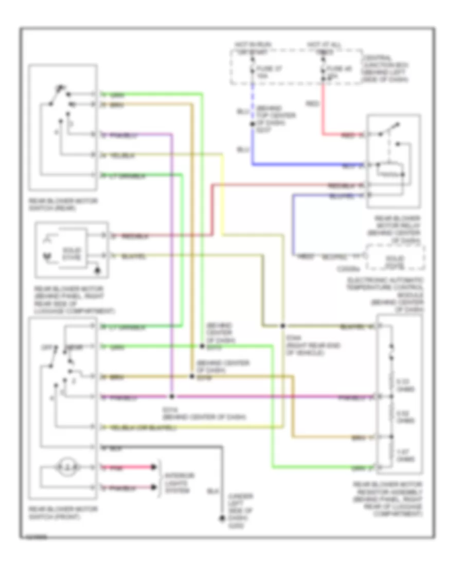
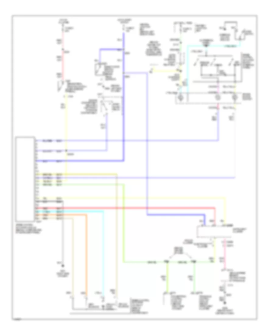
Manual A/C Wiring Diagram, Rear A/C for Mercury Villager Estate 2001
List of elements for Manual A/C Wiring Diagram, Rear A/C for Mercury Villager Estate 2001:
- (behind center of dash)
- (behind center of dash) s313
- (behind center of dash) s318
- (behind right side of dash) g201
- (right rear end of vehicle) s344
- 0.33 ohms
- 0.62 ohms
- 1.67 ohms
- Central junction box (behind left side of dash)
- Front climate control panel
- Fuse 37 10a
- Fuse 45 15a
- Ha05
- Hot at all times
- Hot in run or start
- Interior lights system
- Off
- Pnk
- Rear
- Rear blower motor (behind panel, right rear of luggage compartment)
- Rear blower motor relay (behind center of dash)
- Rear blower motor resistor assembly (behind panel, right rear of luggage compartment)
- Rear blower motor switch (front)
- Rear blower motor switch (rear)
- Red
- S2026
- S314 (behind center of dash)
- Solid state
- Top center of dash) s237
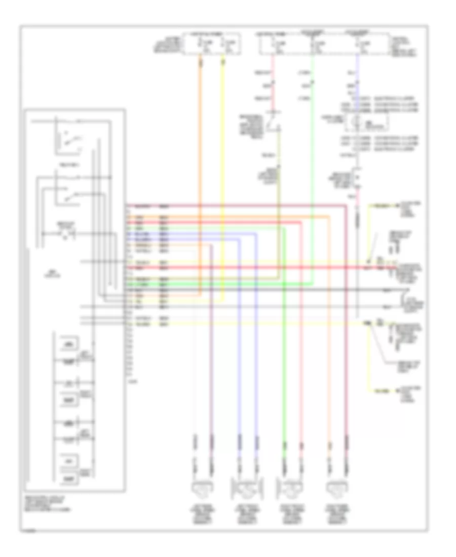
ANTI-LOCK BRAKES
Anti-lock Brake Wiring Diagrams for Mercury Villager Estate 2001
List of elements for Anti-lock Brake Wiring Diagrams for Mercury Villager Estate 2001:
- (2000)
- (2001)
- (behind left side of dash)
- (behind top center of dash)
- (left rear of engine compt.)
- 2000-01
- Abs control module (left side of engine compartment below master cylinder)
- Abs diode (behind top left side of dash)
- Abs indicator
- Abs module
- Abs pump motor
- Battery junction box (left front of engine compt)
- Brake pedal position (bpp) switch (on bracket above brake pedal)
- Bs01
- Bs04
- Bs05
- Bs08
- Bs09
- Bs21
- Bs23
- Bs24
- Bs25
- Bs26
- Bs29
- Bs30
- Bs40
- Bs41
- Bs50
- Bs51
- C249
- C252
- C266b
- C267c
- Central junction box (behind left side of dash)
- Computer data lines system
- Connector (behind left side of dash)
- Conventional cluster
- Diagnostic c2018
- Diagnostic connector c2018
- Dump
- Eb10
- Eb20
- Electronic cluster
- Fuse 10a
- Fuse 20a
- Fuse 40a
- G116
- Hot at all times
- Hot in start or run
- Instrument cluster
- Iso
- Left front
- Left front wheel speed sensor (on wheel assembly)
- Left rear
- Left rear wheel speed sensor (on wheel assembly)
- Nca
- Pnk
- Red
- Relay box
- Right front
- Right front wheel speed sensor (on wheel assembly)
- Right rear
- Right rear wheel speed sensor (on wheel assembly)
- S2006 (left side of engine compt)
- S239
- S244
- S260
- S271
- S272
ANTI-THEFT
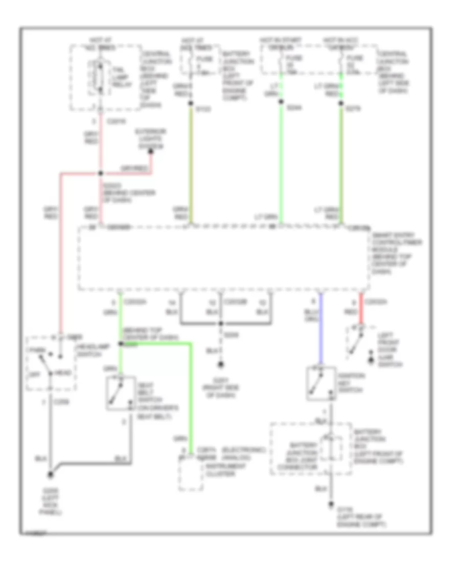
Anti-theft Wiring Diagram (1 of 2) for Mercury Villager Estate 2001
List of elements for Anti-theft Wiring Diagram (1 of 2) for Mercury Villager Estate 2001:
- (1999, 2000)
- (behind top center of dash)
- (left front of engine compt) engine compartment relay box
- (left rear of engine compt) g116
- (right side of dash) g201
- 20a
- Anti- theft 'on' indicator
- Anti-theft relay
- Battery junction box (on left front of engine compt)
- Battery junction box joint connector
- C2032a
- C2032b
- C242
- Central junction box (behind left side of dash)
- Circuit breaker 1 (behind left side of dash)
- Engine compartment switch (1999, 2000)
- Er05
- Er10
- Front power windows only
- Full power windows
- Fuse 35 10a
- Fuse 4 7.5a
- Fuse 49 10a
- Fuse 52 7.5a
- G105 (rear of right front fender)
- G200 (left kick panel)
- G201 (right side of dash)
- G999 (top of left rear pillar)
- Horns system
- Hot at all times
- Hot in run or accy
- Hot in run or start
- Ignition key switch
- Interior lights system
- Left front door ajar switch
- Left liftgate ajar switch
- Left sliding door ajar switch
- Li87
- Li89
- Li90
- Li94
- Lock
- Master window/ door lock/ unlock switch
- Passenger window/ door lock/ unlock switch
- Ph10
- Ph19
- Ph35
- Ph38
- Ph43
- Pnk
- Ps95
- Red
- Right front door ajar switch
- Right liftgate ajar switch
- Right sliding door ajar switch
- S133
- S2040 (behind center of dash)
- S206
- S227
- S240
- S244
- S267
- S268
- S279
- S403
- S414 (right side of liftgate)
- S501
- S600
- Sc06
- Sc09
- Sc11
- Sc13
- Sc14
- Sc15
- Sc16
- Sc18
- Sc21
- Sc24
- Sce1
- Sce2
- Sce3
- Smart entry control (sec)/ timer module (behind top center of dash)
- St70
- St96
- Starting/ charging system
- Unlk
Anti-theft Wiring Diagram (2 of 2) for Mercury Villager Estate 2001
List of elements for Anti-theft Wiring Diagram (2 of 2) for Mercury Villager Estate 2001:
- (behind center of dash) s2049
- (left rear of vehicle) s330
- (left rear of vehicle) s331
- (left side of sliding door) s307
- (right side of sliding door) s308
- Driver side door lock actuator assembly
- Driver side key lock switch
- G200 (left kick panel)
- G201 (right side of dash)
- G999 (top of left rear pillar)
- Left sliding door lock actuator assembly
- Liftgate key lock switch
- Liftgate lock actuator assembly
- Lock
- Nca
- Passenger side door lock actuator assembly
- Passenger side key lock switch
- Red
- Right sliding door lock actuator assembly
- S2503 (behind center of dash)
- S274 (behind top center of dash)
- S275 (behind top center of dash)
- S303 (behind center top of dash)
- S332 (left rear of vehicle)
- S403
- S404
- S501
- S600
- Sliding door contact assemblies
- Unlk
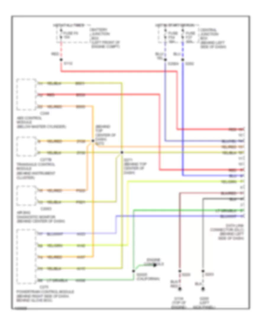
COMPUTER DATA LINES
Computer Data Lines for Mercury Villager Estate 2001
List of elements for Computer Data Lines for Mercury Villager Estate 2001:
- (behind instrument cluster)
- (behind top center of dash) s272
- Abs control module (below master cylinder)
- Air bag diagnostic monitor (behind center of dash)
- Av07
- Av15
- Av23
- Av42
- Aw08
- Battery junction box (left front of engine compt)
- Bs30
- Bs50
- Bs51
- C2003
- C249
- C275
- C277b
- Central junction box (behind left side of dash)
- Data link connector (dlc) (behind left side of dash)
- Engine controls
- Fuse f37 10a
- Fuse f54 10a
- Fuse f6 10a
- G134 (top of engine)
- G200 (left kick panel)
- Hot at all times
- Hot in start or run
- Powertrain control module (behind right side of dash, behind glove box)
- Ps20
- Ps21
- Red
- S112
- S2024
- S2025 (california)
- S203
- S220
- S262
- S271 (behind top center of dash)
- Transaxle control module
- Zy28
- Zy30
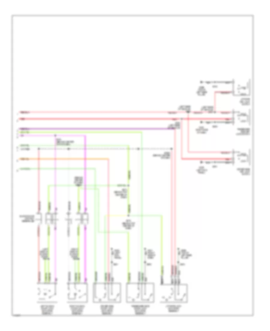
COOLING FAN
Cooling Fan Wiring Diagram for Mercury Villager Estate 2001
List of elements for Cooling Fan Wiring Diagram for Mercury Villager Estate 2001:
- (behind top center dash panel) s219
- (left rear side of engine compartment) g104
- (top of engine) g134
- Av15
- Av21
- Aw16
- Aw17
- Battery junction box (bjb) (on left front of engine compartment)
- Battery junction box (bjb) (on left front of engine compartment)
- Battery junction box (bjb) joint connector
- Central junction box (behind left side of dash)
- Dual pressure switch (1: normal pressure) (2: high pressure) (in right front of engine compartment)
- Engine coolant temperature (ect) sensor (on left rear of engine)
- Engine cooling fan motor (behind radiator)
- Fa06
- Fa12
- Fuse 10a
- Fuse 20a
- Fuse 7.5a
- Fuse 75a
- High speed fan control relay 1
- High speed fan control relay 2
- Hot at all times
- Hot in run or start
- Hx01
- Low speed fan control relay
- Powertrain control module (pcm) (behind right side of dash, behind glove box)
- S116 (front of engine compartment)
- S158 (left front side of engine compartment)
- S159 (left front side of engine compartment)
- S269 (right side of engine compartment)
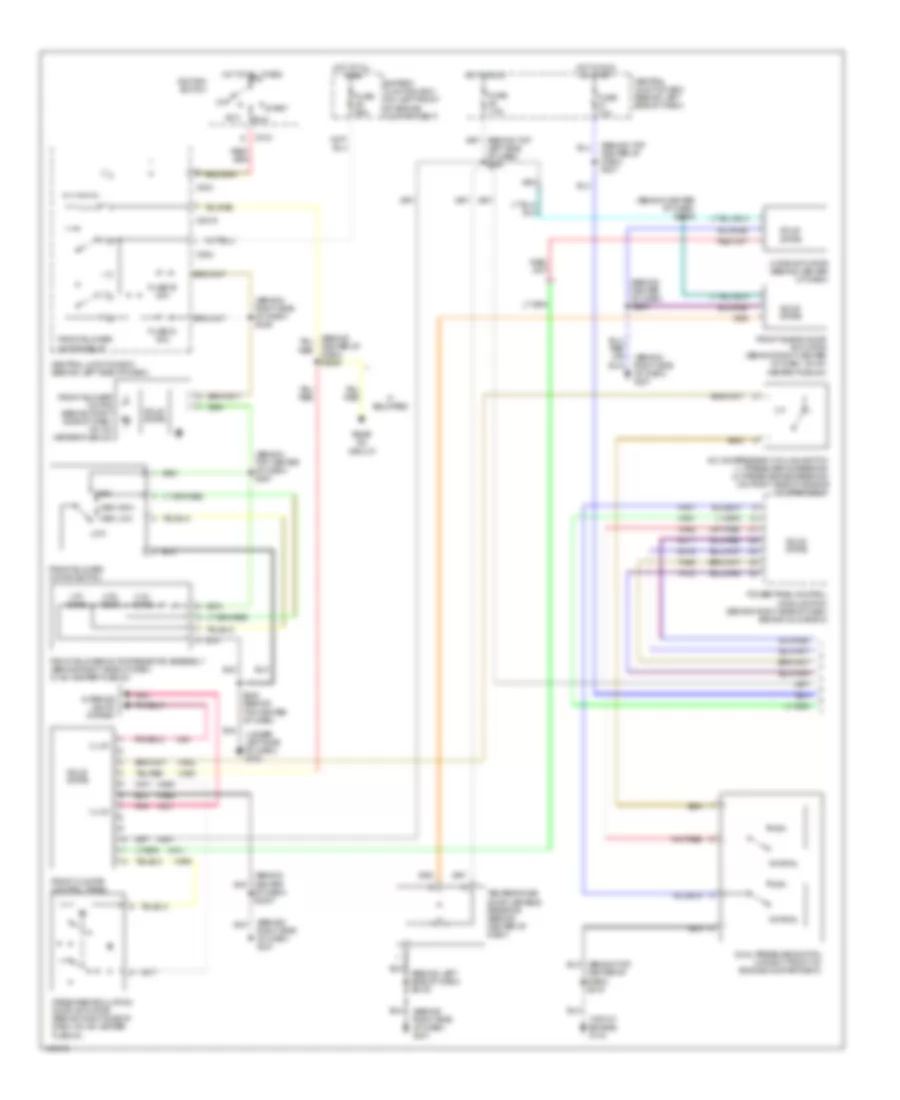
CRUISE CONTROL
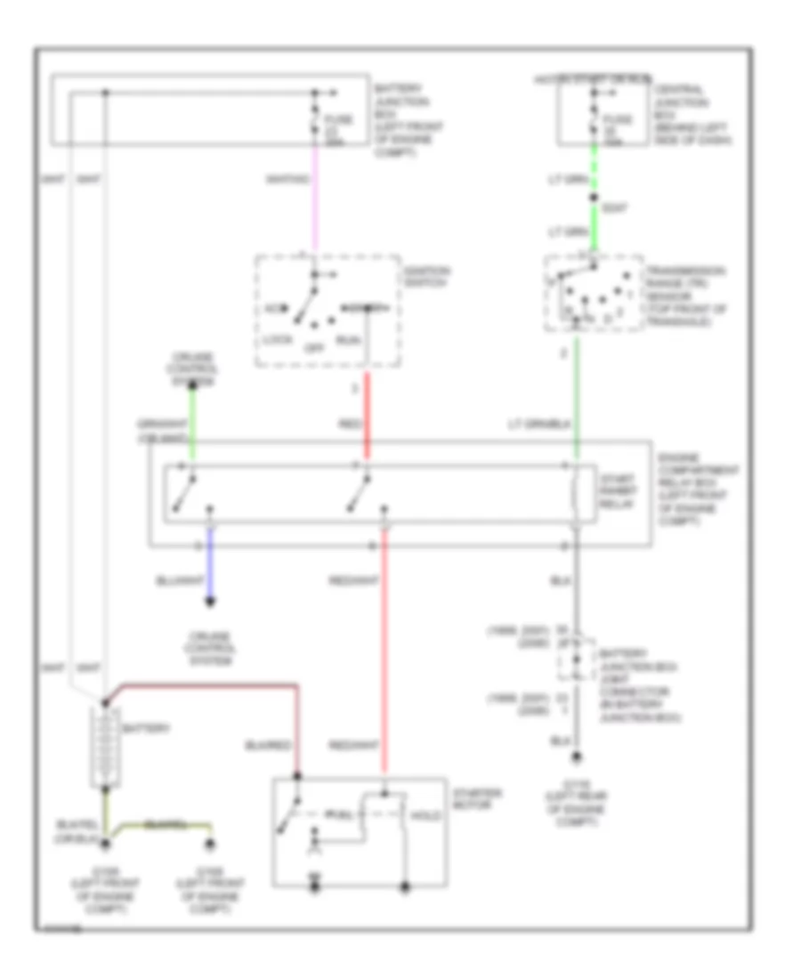
Cruise Control Wiring Diagram for Mercury Villager Estate 2001
List of elements for Cruise Control Wiring Diagram for Mercury Villager Estate 2001:
- (behind center of dash)
- (behind center top of dash) smart entry control (sec) timer module
- (behind left side of dash)
- (in steering wheel) s2021
- (on right rear of engine compartment)
- Air bag sliding contact
- Analog cluster
- Battery junction box
- Brake pedal position switch (above brake pedal)
- C174
- C180
- C247
- C266b
- C267a
- C275
- C277b
- C278
- Cancel
- Central junction box (behind left side of dash)
- Deactivator switch (top of brake pedal support)
- Ej01
- Ej02
- Ej04
- Ej06
- Ej07
- Ej09
- Ej10
- Ej14
- Ej15
- Ej16
- Ej23
- Ej40
- Eje1
- Electronic cluster
- Engine compartment relay box (left front of engine compartment)
- Fuse 13 15a
- Fuse 37 10a
- Fuse 51 20a
- G201 (right side of dash)
- G206 (behind right center of dash)
- Horn relay (in engine compt relay box)
- Horn switch
- Hot at all times
- Hot at all times
- Hot in start or run
- Instrument cluster
- Ohms
- Powertrain control module (behind right side of dash)
- Red
- Red/
- Resume/ accel
- S115
- S140 (in engine compt)
- S2006
- S229
- S239
- S254
- S255
- S258
- S262
- S285
- Set/ coast
- Speed control actuator
- Speed control actuator module (behind lower center of instrument panel)
- Speed control actuator switch (steering wheel)
- Start inhibit relay
- Steering column ground
- Transaxle control module (behind instrument cluster)
- Vacuum pump motor
- Vacuum solenoid
- Vehicle speed sensor (on right side of transaxle)
- Vent solenoid
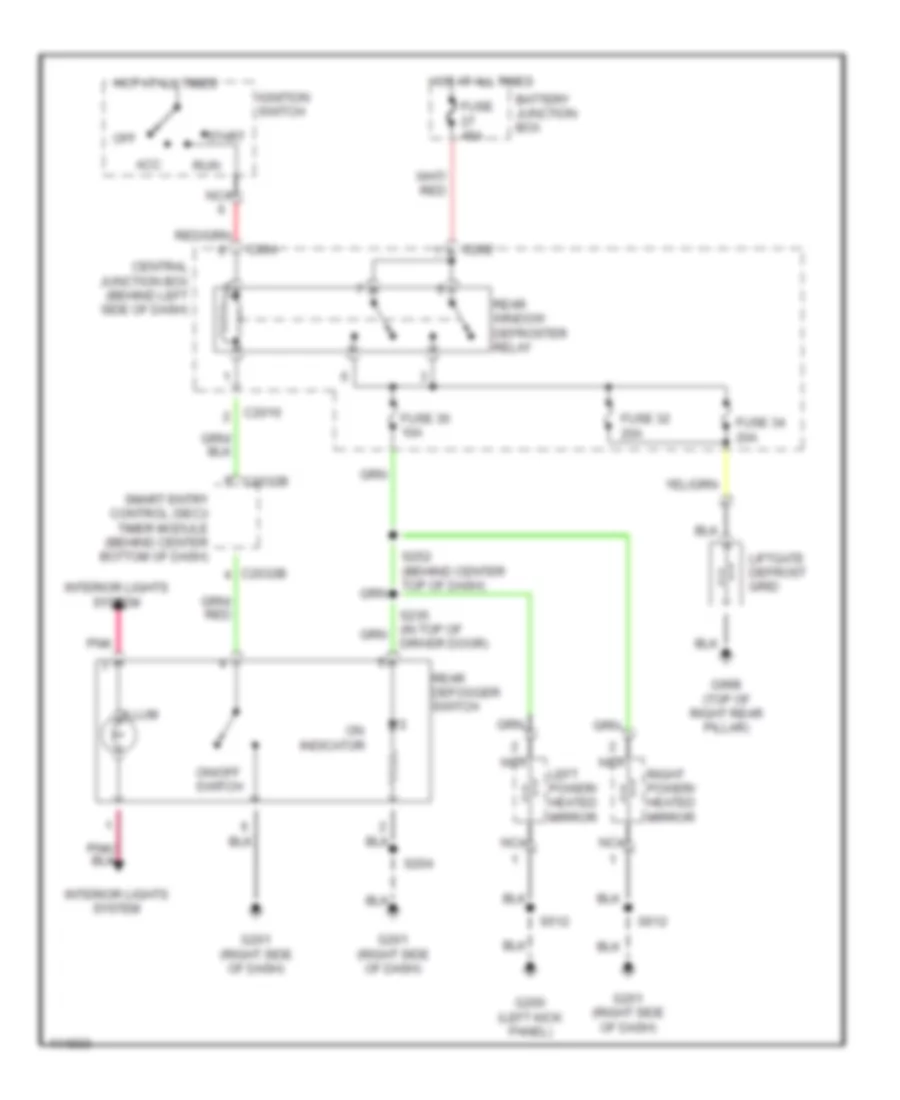
DEFOGGERS
Defogger Wiring Diagram for Mercury Villager Estate 2001
List of elements for Defogger Wiring Diagram for Mercury Villager Estate 2001:
- Acc
- Battery junction box
- C2016
- C202
- C2032b
- C204
- Central junction box (behind left side of dash)
- Driver door)
- Fuse 30 10a
- Fuse 32 20a
- Fuse 34 20a
- Fuse 45a
- G200 (left kick panel)
- G201 (right side of dash)
- G998 (top of right rear pillar)
- Hot at all times
- Ignition switch
- Illum
- Indicator
- Interior lights system
- Left power/ heated mirror
- Liftgate defrost grid
- Nca
- Off
- On/off switch
- Pnk
- Rear defogger switch
- Rear window defroster relay
- Right power/ heated mirror
- Run
- S204
- S252 (behind center top of dash)
- S512
- S612
- Smart entry control (sec)/ timer module (behind center bottom of dash)
- Start
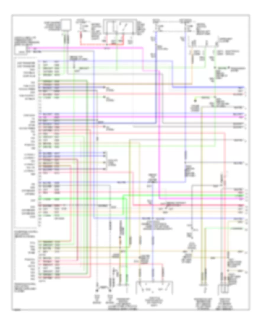
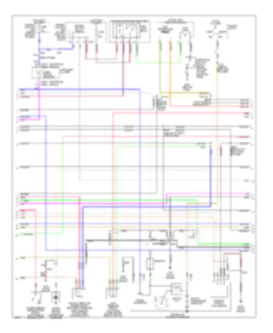
ENGINE PERFORMANCE
3.3L
3.3L, Engine Performance Wiring Diagrams (1 of 3) for Mercury Villager Estate 2001
List of elements for 3.3L, Engine Performance Wiring Diagrams (1 of 3) for Mercury Villager Estate 2001:
- mil
- (analog)
- (behind top center of dash)
- (center rear of engine s134
- (electronic)
- (federal) (near engine)
- (near trans)
- (on throttle body assembly)
- (or aw30)
- A/c dual press
- A/c high press
- A/c relay
- A/c system
- Av01
- Av02
- Av04
- Av05
- Av09
- Av12
- Av19
- Av20
- Av22
- Av23
- Av30
- Av31
- Av32
- Av33
- Av34
- Av36
- Av54
- Av56
- Av57
- Av58
- Av61
- Av98
- Aw16
- Aw17
- Aw18
- Aw25
- Battery junction box (on left front of engine compt)
- C266a
- C266b
- C267a
- C277a
- C277b
- Central junction box (behind left side of dash)
- Ckp
- Cmp sensor
- Compt)
- Cooling fans system
- Crankshaft position (ckp) sensor (under intake, in front of
- Cruise control system
- Diag conn
- Dist transister
- Engine coolant temperature (ect) sensor (on left rear of engine)
- Ep06
- Ep13
- Es39
- Es48
- Evap canister purge valve (on right side of engine)
- Evap valve
- Fa06
- Fa12
- Fuel flow
- Fuel pump rly
- Fuse 10a
- Fuse 7.5a
- G134 (top of engine)
- Gnd
- Ha41
- Ha45
- Hi fan rly
- Ho2s
- Hot at all times
- Hot in run or start
- Hot in start
- Hx01
- Idle
- Ign
- Instrument cluster
- Lo fan rly
- Manifold absolute pressure (map)/ barometric pressure (baro) solenoid
- Map/baro
- Nca
- Nr01
- Pcm
- Pcm power relay (behind glove box)
- Pcm relay
- Pnk
- Powertrain control module (pcm) (behind glove box)
- Psg
- Psp
- Red
- S108
- S110
- S112
- S154 s1002 (california) (top left side of engine compt)
- S2036 (behind left side of dash)
- S219
- S222
- S238 (with drl)
- S241
- S242 (behind top center of dash)
- S257
- S265
- S278
- St sig
- System transmission
- Tach
- Tcm
- Tcm (tp)
- Throttle position (tp) sensor
- Throttle position switch (on throttle body)
- Tp in
- Tp ref
- Tp switch
- Transaxle control module (tcm) (behind instrument cluster)
- Transaxle, near flywheel)
- Transmission system
- Vss
- Wot
- Wot in
- Zy13
- Zy14
- Zy21
- Zy24
- Zy31
- Zy34
- Zy35
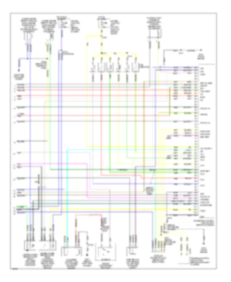
3.3L, Engine Performance Wiring Diagrams (2 of 3) for Mercury Villager Estate 2001
List of elements for 3.3L, Engine Performance Wiring Diagrams (2 of 3) for Mercury Villager Estate 2001:
- (analog)
- (at fuel tank) fuel pump module
- (baro) sensor (on left rear of engine compt)
- (behind top right side of dash)
- (california) (under center rear of vehicle)
- (electronic)
- Acc
- Battery junction box (on left front of engine compt)
- Battery junction box j/c
- C1000
- C146a
- C146b
- C266a
- C266b
- C267c
- Camshaft position (cmp) sensor
- Central junction box (behind left side of dash)
- Check engine indicator
- Distributor (on front of engine)
- Engine compartment relay box
- Evap pressure sensor
- Fuel pump
- Fuel pump relay
- Fuel temperature sensor
- Fuse 10a
- Fuse 15a
- G134 (top of engine)
- G200 (left kick panel)
- Hot at all times
- Hot in run or start
- Ignition coil
- Ignition switch
- Ignition transformer capacitor
- Inertia fuel shut-off switch (behind left side of dash, above kick panel)
- Instrument cluster
- Knock sensor (on top center rear of engine)
- Manifold absolute pressure (map)/ barometric pressure
- Nca
- Off
- Pnk
- Power steering pressure (psp) switch (right rear of engine compt)
- Power transistor
- Red
- Resistor
- Run
- S108
- S109
- S119 (behind left side of dash)
- S121
- S237
- S260 (or s262)
- S263
- S264 (behind top right side of dash)
- S269 (right side of engine compt)
- S299
- Start
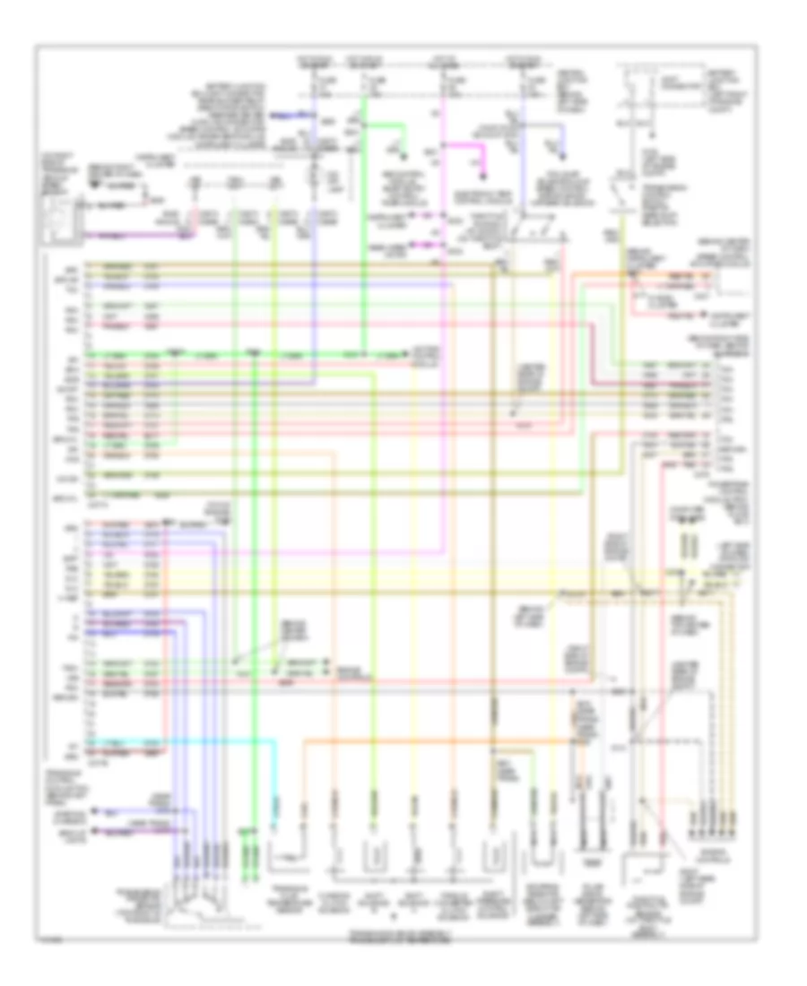
3.3L, Engine Performance Wiring Diagrams (3 of 3) for Mercury Villager Estate 2001
List of elements for 3.3L, Engine Performance Wiring Diagrams (3 of 3) for Mercury Villager Estate 2001:
- (behind top center of dash)
- (behind top right side of dash)
- (not used)
- (on front left corner of engine compt) intake air
- (under center rear of vehicle) evap canister purge vacuum cut valve by-pass solenoid (california)
- (under center rear of vehicle) evap canister vent control solenoid (california)
- A/c relay
- Av07
- Av08
- Av15
- Av16
- Av17
- Av18
- Av21
- Av25
- Av27
- Av28
- Av37
- Av38
- Av42
- Av46
- Av47
- Av51
- Av52
- Av53
- Av55
- Av59
- Av60
- Av62
- Av63
- Av64
- Aw06
- Aw08
- Aw12
- Aw28
- Aw41
- Aw43
- Battery junction box (on left front of engine compt)
- C277b
- Central junction box (behind left side of dash)
- Computer data lines system
- Data link connector (dlc) (behind left side of dash)
- Diag conn
- Ect
- Egr temp
- Egrv
- Engine compartment relay box
- Ep57
- Ep58
- Es90 (or es10)
- Evap
- Evap bypass
- Evap vent
- Fuel injectors
- Fuel temp
- Fuse 10a
- Fuse 7.5a
- G134 (top of engine)
- G201 (behind right side of dash)
- Gnd
- Heated oxygen sensor (ho2s) (front) (left rear of engine, in exhaust)
- Heated oxygen sensor (ho2s) (rear) (california) (underneath vehicle, near center of vehicle)
- Ho2s
- Ho2s htr
- Hot at all times
- Hot in run or start
- Iat
- Idle speed control (isc) (on top rear center of engine)
- Inj 1
- Inj 2
- Inj 3
- Inj 4
- Inj 5
- Inj 6
- Isc
- Iso bus
- Maf
- Map/baro
- Mass airflow (maf) sensor (on left side of engine compt)
- Nca
- Pcm rly in
- Powertrain control module (pcm) (behind glove box)
- Red
- Ref voltage
- S1003
- S110
- S114
- S118
- S129
- S2024 (behind top center of dash)
- S2025
- S219
- S272 (behind top center of dash)
- Sig rtn
- Temperature (iat) sensor
- Transaxle control module (tcm) (behind instrument cluster)
- Zy28
- Zy30
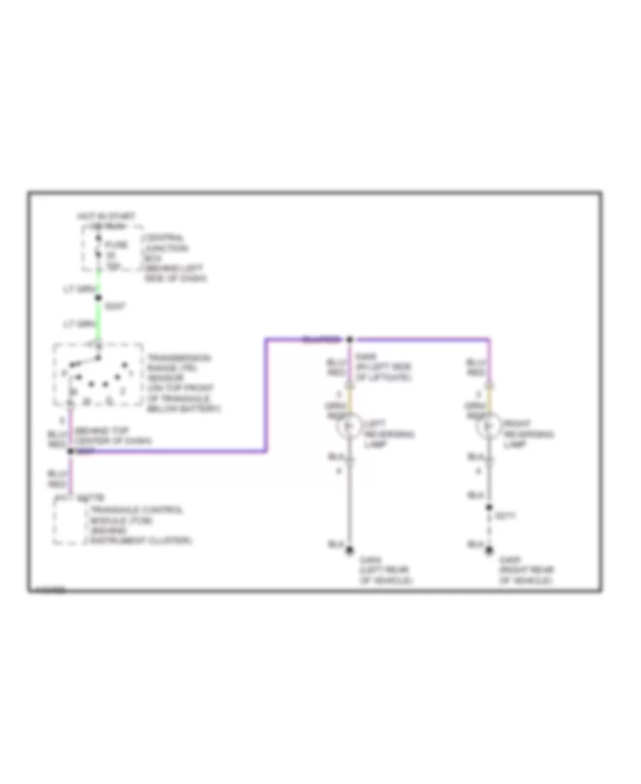
EXTERIOR LIGHTS
Back-up Lamps Wiring Diagram for Mercury Villager Estate 2001
List of elements for Back-up Lamps Wiring Diagram for Mercury Villager Estate 2001:
- C277b
- Central junction box (behind left side of dash)
- Fuse 10a
- G404 (left rear of vehicle)
- G405 (right rear of vehicle)
- Hot in start or run
- Left reversing lamp
- Right reversing lamp
- S211
- S247
- Transaxle control module (tcm) (behind instrument cluster)
- Transmission range (tr) sensor (on top front of transaxle, below battery)
Exterior Lamps Wiring Diagram for Mercury Villager Estate 2001
List of elements for Exterior Lamps Wiring Diagram for Mercury Villager Estate 2001:
- (behind center of dash)
- (behind left side of dash)
- (behind top center of dash) smart entry control (sec)/timer module
- (left rear of vehicle)
- (on brake pedal support)
- (right side of dash) g201
- (right side of engine bulkhead)
- Analog
- Auto
- Autolamp sensor (on top right side of dash, near windshield)
- Battery junction box (on left front of engine compt)
- Battery junction box joint connector (in battery junction box)
- Brake pedal position switch (on bracket, above brake pedal)
- C1000
- C2016
- C2032b
- C206
- C224a
- C224b
- C258
- C292
- C349
- C350
- Electronic
- Electronic flasher module (behind left side of dash)
- Fuse 100a
- Fuse 10a
- Fuse 20a
- Fuse junction panel (behind dash, left of steering column)
- G105 (rear of right front fender)
- G116 (left rear of engine compt)
- G200 (left kick panel)
- G201 (right side of dash)
- G404 (left rear of vehicle)
- G405 (right rear of vehicle)
- G999 (top of left rear pillar)
- Hazard flasher switch
- Head
- Headlamp switch
- Headlights system (fog lamp switch)
- High mounted stoplamp
- Hot at all times
- Hot in start or run
- Instrument cluster
- Instrument illumination
- Left front park/turn lamp
- Left front side lamp
- Left front turn lamp
- Left license lamp
- Left rear park/stop lamp
- Left rear turn lamp
- Lft ind grd
- Lft turn ind
- Lighting control module (behind center of dash)
- Multifunction switch
- Nca
- Off
- Park
- Pnk
- Red
- Right front park/turn lamp
- Right front side lamp
- Right front turn lamp
- Right license lamp
- Right rear park/stop lamp
- Right rear turn lamp
- Rt ind grd
- Rt turn ind
- S146
- S147 (right side of engine bulk- head)
- S2003 (behind left side of dash)
- S2004 (behind left side of dash)
- S2005 (behind left side of dash)
- S2023
- S204
- S211
- S239
- S240
- S251
- S317
- S325
- S326
- S327
- S402
- S406
- S407
- S408
- S413
- Tail lamp relay
- Trailer tow circuit
- W/ autolamps
- W/o autolamps
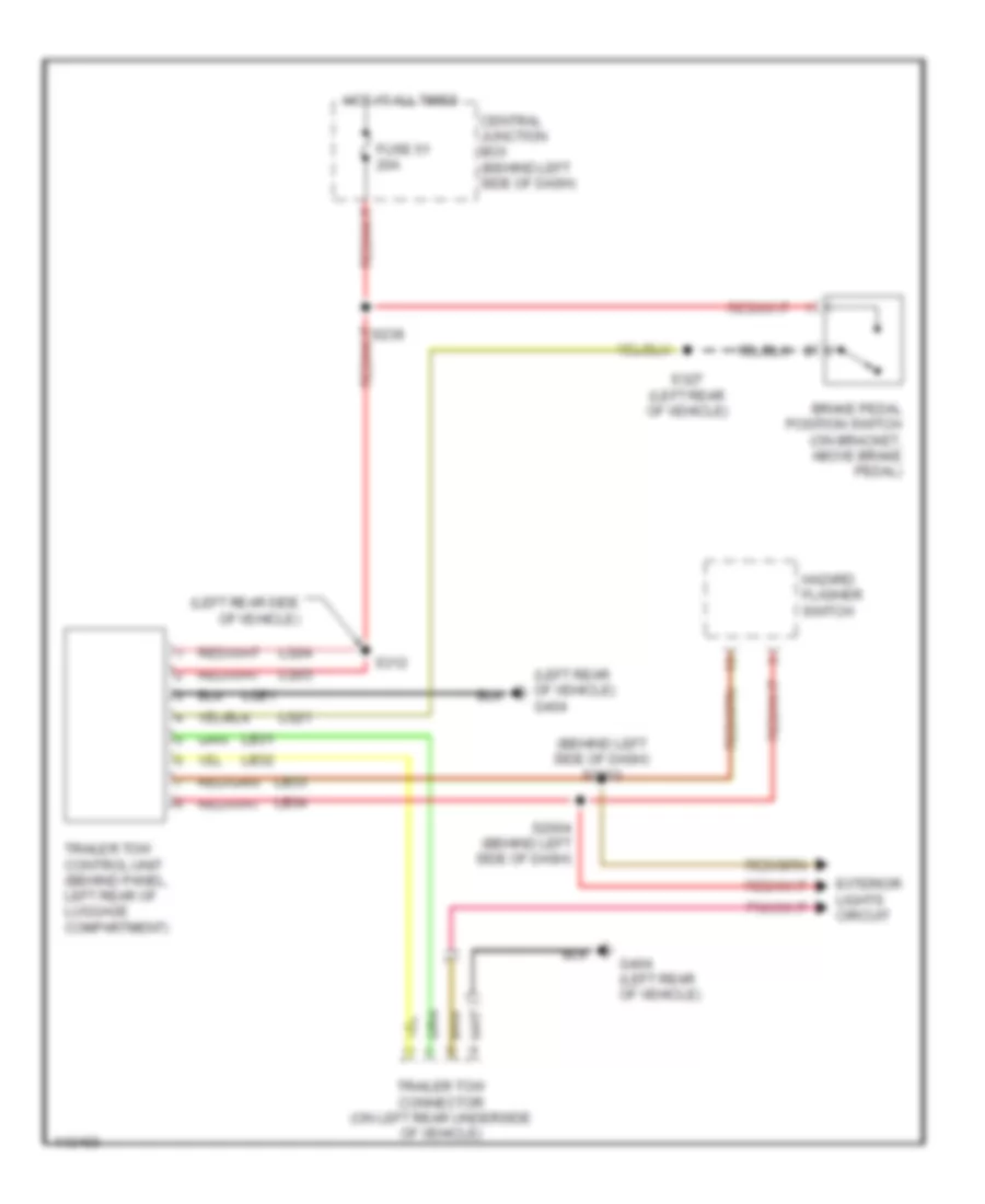
Trailer Tow Wiring Diagram for Mercury Villager Estate 2001
List of elements for Trailer Tow Wiring Diagram for Mercury Villager Estate 2001:
- (behind left side of dash) s2003
- (left rear of vehicle) g404
- (left rear side of vehicle)
- Brake pedal position switch (on bracket, above brake pedal)
- Central junction box (behind left side of dash)
- Exterior lights circuit
- Fuse 51 20a
- G404 (left rear of vehicle)
- Hazard flasher switch
- Hot at all times
- Lb31
- Lb32
- Lb33
- Lb34
- Lq03
- Lq04
- Lq21
- Lqe1
- S2004 (behind left side of dash)
- S239
- S312
- S327 (left rear of vehicle)
- Trailer tow connector (on left rear underside of vehicle)
- Trailer tow control unit (behind panel, left rear of luggage compartment)
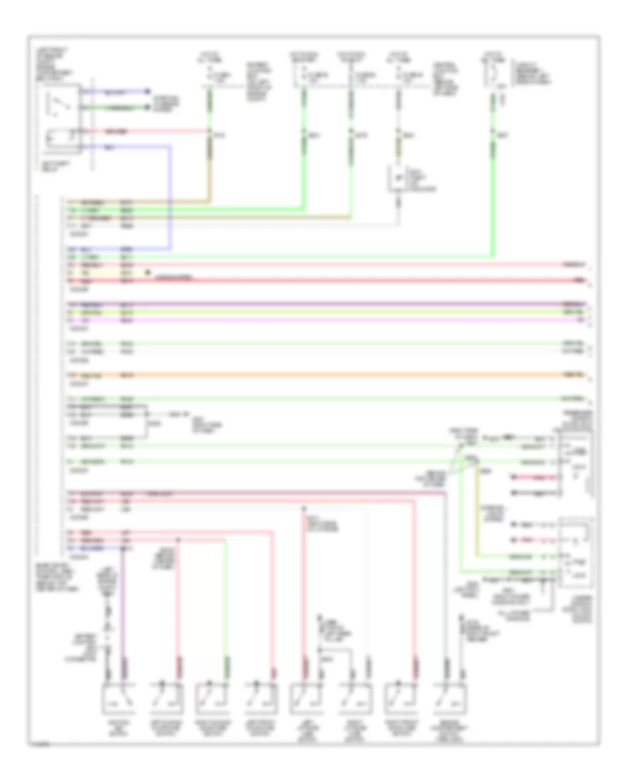
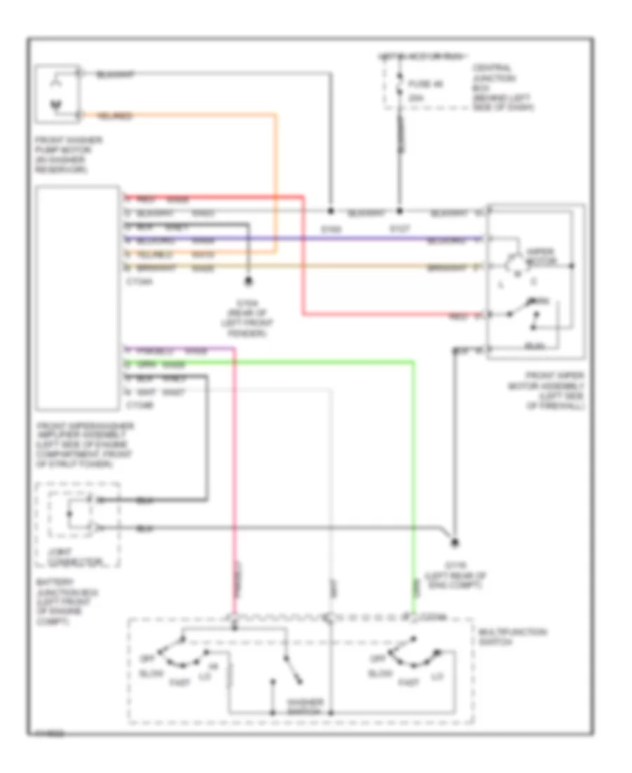
GROUND DISTRIBUTION
Ground Distribution Wiring Diagram (1 of 3) for Mercury Villager Estate 2001
List of elements for Ground Distribution Wiring Diagram (1 of 3) for Mercury Villager Estate 2001:
- (california) heated oxygen sensor
- Abs control module
- Accessory relay
- Battery
- Battery junction box
- Battery junction box joint connector
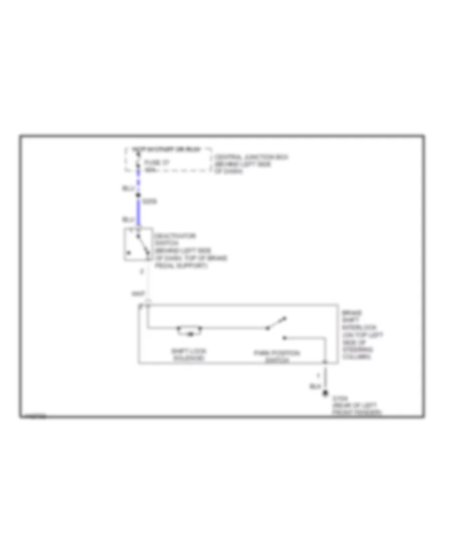
- Brake fluid level switch
- Brake shift interlock
- Bulb check relay
- C134a
- C146a
- C204
- C224
- Central junction box
- Data link connector
- Distributor
- Dual pressure switch
- Elec cluster
- Engine compartment relay box
- Engine cooling fan motor
- Fog lamp switch
- Front wiper/ washer amplifier assembly
- G104 (rear of left front fender)
- G105 (rear of right front fender)
- G106 (left front of engine compt)
- G112 (left side of engine compt)
- G116 (left rear of engine compt)
- G134 (on top of engine)
- G998 (top of right rear pillar)
- Generator
- Ignition key switch
- Ignition relay
- Left front fog lamp
- Left front park/ turn lamp
- Left front side lamp
- Left front turn lamp
- Left head- lamp
- Multifunction switch
- Outside temperature sensor
- Powertrain control module
- Rear window defrost grid
- Right front fog lamp
- Right front park/ turn lamp
- Right front side lamp
- Right front turn lamp
- Right headlamp
- S108 (right side of engine)
- S109 (right side of engine)
- S110 (right side of engine)
- S219 (top center of dash)
- S220 (right side of dash)
- S221 (near trans)
- S222 (right side of dash)
- Shield
- Side of engine compt)
- Speed control hold relay
- Start inhibit relay
- To g200 (diagram 2 of 3)
- Transaxle control module
- Transmission control switch
- Washer fluid level switch
- Windshield wiper motor
Ground Distribution Wiring Diagram (2 of 3) for Mercury Villager Estate 2001
List of elements for Ground Distribution Wiring Diagram (2 of 3) for Mercury Villager Estate 2001:
- A/c clutch solenoid
- A/c compressor clutch diode
- Air bag diagnostic monitor
- Air bag sliding contact
- C2032a
- C2032b
- C266b
- C267b
- C267c
- C502a
- C614a
- Console power
- Console power point 2
- Conv cluster
- Data link connector
- Driver door lock actuator assembly
- Driver exterior rear view mirror
- Driver key lock switch
- Driver seat heater switch
- Elec cluster
- Electronic automatic temperature control module
- Electronic flasher module
- Exterior rear view mirror switch
- From g104 (diagram 1 of 3)
- Front & rear
- Front blend door actuator
- Front blower motor resistor assembly
- Front blower motor speed controller
- Front blower motor switch
- Front cigar lighter
- Front climate control panel
- Front only
- G200 (left kick panel)
- G201 (right side of dash)
- G405 (right rear of vehicle)
- Headlamp switch
- Idle speed control
- Illumination dimmer
- Inertia fuel shutoff switch
- Instrument cluster
- Left front door ajar switch
- Left power seat switch
- Left vanity mirror lamp
- Lighting control module
- Manual a/c
- Master window/ door lock/ unlock switch
- Memory set switch
- Mode actuator
- Nca
- Of dash)
- Passenger door lock actuator assembly
- Passenger door lock/ unlock switch
- Passenger door)
- Passenger exterior rear view mirror
- Passenger key lock switch
- Passenger seat heater switch
- Rear axle)
- Rear blower motor relay
- Rear blower motor switch
- Rear radio control
- Rear window defrost switch
- Rear window wiper/ washer switch
- Right power seat switch
- Right rear lamp assembly
- Right vanity mirror lamp
- Roof opening panel switch
- S1003 (right side of engine compt)
- S2027 (center of dash)
- S203 (left side of dash)
- S2051 (center of dash)
- S2100 (left side of dash)
- S243 (top center of dash)
- S248 (top center of dash)
- S319 (above rear axle)
- S501 (center of driver door)
- S512 (top of driver door)
- S600 (top of
- S612 (top of passenger door)
- S901 (left side of roof panel)
- Safety belt buckle switch
- Smart entry control/ timer module
- Speed control actuator module
- Speed control actuator switch
- Temperature door variable resistor
- To s401 (diagram 3 of 3)
- W/ eatc
Ground Distribution Wiring Diagram (3 of 3) for Mercury Villager Estate 2001
List of elements for Ground Distribution Wiring Diagram (3 of 3) for Mercury Villager Estate 2001:
- (conventional cluster) (electronic cluster)
- C2026a
- C2046a
- C266b c267b
- C393a
- Cd changer
- Center of dash)
- Driver seat module
- From g200 (diagram 2 of 3)
- Fuel pump module
- G206 (behind right
- G206 (behind right center of dash)
- G404 (left
- G999 (top of
- High mounted stoplamp
- Instrument cluster
- Left license plate lamp
- Left liftgate ajar switch
- Left rear lamp assembly
- Left rear pillar)
- Lift- gate glass ajar switch
- Liftgate door lock actuator assembly
- Liftgate glass
- Liftgate key lock switch
- Nca
- Of dash)
- Radio
- Rear of vehicle)
- Rear power point
- Rear seat entertainment (rse) module
- Rear wiper motor assembly
- Right license plate lamp
- Right liftgate ajar switch
- S401 (left
- S403 (right side of liftgate)
- S404 (right side of liftgate)
- S411 (right
- S413 (right side of liftgate)
- Side of dash)
- Side of liftgate)
- Subwoofer amplifier
- Trailer tow
- Trailer tow control unit
- Vehicle speed sensor
- Vehicle)
- Video cassette player
- Video display
- W/ moveable
- W/ rear seat entertainment system
- W/o moveable
- W/o rear seat entertainment system
HEADLIGHTS
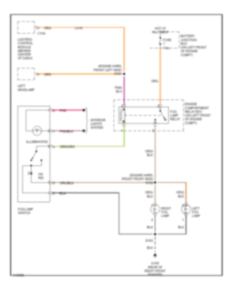
Fog Lamp Wiring Diagram for Mercury Villager Estate 2001
List of elements for Fog Lamp Wiring Diagram for Mercury Villager Estate 2001:
- (engine harn, front front side) s162
- (engine harn, front left side) s161
- 7.5a
- Battery junction box (on left front of engine compt)
- C104
- Engine compartment relay box (on left front of engine compt)
- Fog lamp relay
- Fog lamp switch
- Fuse
- G105 (rear of right front fender)
- Hot at all times
- Illumination
- Interior lights system
- La16
- Left fog lamp
- Left headlamp
- Lighting control module (behind center of dash)
- On ind
- Pnk
- Right fog lamp
- S163
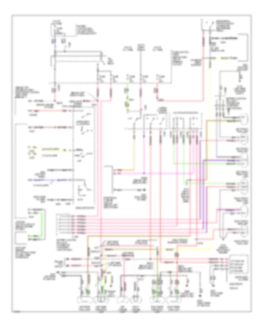
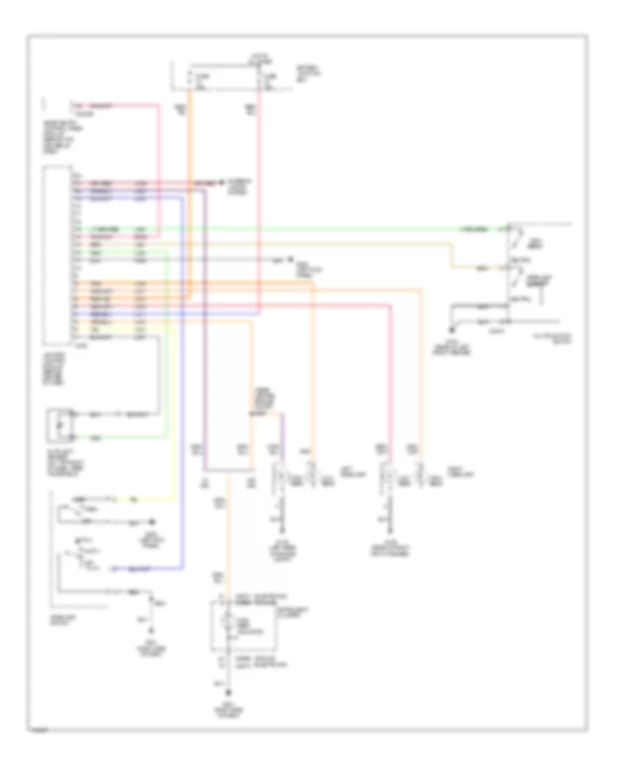
Headlamps Wiring Diagram, with Autolamps for Mercury Villager Estate 2001
List of elements for Headlamps Wiring Diagram, with Autolamps for Mercury Villager Estate 2001:
- (analog)
- (electronic)
- (rear center engine compt) s297
- Auto 1
- Auto 2
- Autolamp sensor (on top right of dash, near windshield)
- Battery junction box
- C2032b
- C224a
- C266b
- C267c
- C349
- Exteror lights system
- Fuse 15a
- G104 (rear of left front fender)
- G105 (rear of right front fender)
- G116 (left rear of engine compt)
- G200 (left kick panel)
- G201 (right side of dash)
- Head
- Headlamp flasher
- Headlamp switch
- High beam
- High beam indicator
- Hot at all times
- Instrument cluster
- La03
- La11
- La12
- La14
- La15
- La16
- La17
- La18
- La21
- La23
- Lc45
- Left headlamp
- Lighting control module (behind center of dash)
- Low beam
- Lx03
- Lx04
- Lx07
- Multifunction switch
- Neutral
- Off
- Park
- Pre1
- Right headlamp
- S204
- Sc23
- Smart entry control/timer module (behind top center of dash)
- W/ drl
- W/o drl
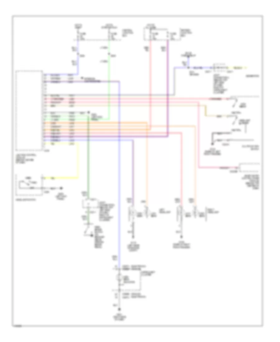
Headlamps Wiring Diagram, with DRL for Mercury Villager Estate 2001
List of elements for Headlamps Wiring Diagram, with DRL for Mercury Villager Estate 2001:
- (analog)
- (electronic)
- Battery junction box
- Bulb check relay
- C2011
- C2032b
- C224a
- C258
- C266b
- C267c
- C349
- Central junction box
- Exterior lights system
- Fuse 10a
- Fuse 15a
- Fuse 7.5a
- G104 (rear of left front fender)
- G105 (rear of right front fender)
- G116 (left rear of engine compt)
- G200 (left kick panel)
- G201 (right side of dash)
- Generator
- Head
- Headlamp flasher
- Headlamp switch
- High beam
- High beam indicator
- Hot at all times
- Hot in start
- Hot in start or run
- Instrument cluster
- Joint connector 2 (behind top left side of dash, right of instrument cluster)
- La03
- La11
- La12
- La14
- La15
- La16
- La17
- La18
- La21
- La23
- Lc45
- Left headlamp
- Lighting control module (behind center of dash)
- Low beam
- Multifunction switch
- Neutral
- Off
- Park
- Park brake switch (on bracket above parking brake pedal)
- Pr01
- Pr05
- Pr11
- Pr12
- Pre1
- Right headlamp
- S141 (engine)
- S238
- S245
- Sc23
- Smart entry control/timer module) (behind top center of dash)
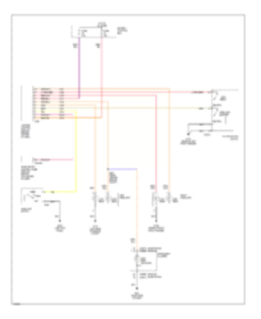
Headlamps Wiring Diagram, without Autolamps for Mercury Villager Estate 2001
List of elements for Headlamps Wiring Diagram, without Autolamps for Mercury Villager Estate 2001:
- (analog)
- (electronic)
- Battery junction box
- C2032b
- C224a
- C258
- C266b
- C267c
- C350
- Fuse 15a
- G104 (rear of left front fender)
- G105 (rear of right front fender)
- G116 (left rear of engine compt)
- G200 (left kick panel)
- G201 (right side of dash)
- Head
- Headlamp flasher
- Headlamp switch
- High beam
- High beam indicator
- Hot at all times
- Instrument cluster
- La11
- La12
- La14
- La15
- La16
- La17
- La18
- La21
- La23
- Left headlamp
- Lighting control module (behind center of dash)
- Low beam
- Multifunction switch
- Neutral
- Off
- Park
- Right headlamp
- S297 (rear center engine compt)
- Sc23
- Smart entry control/timer module (behind top center of dash)
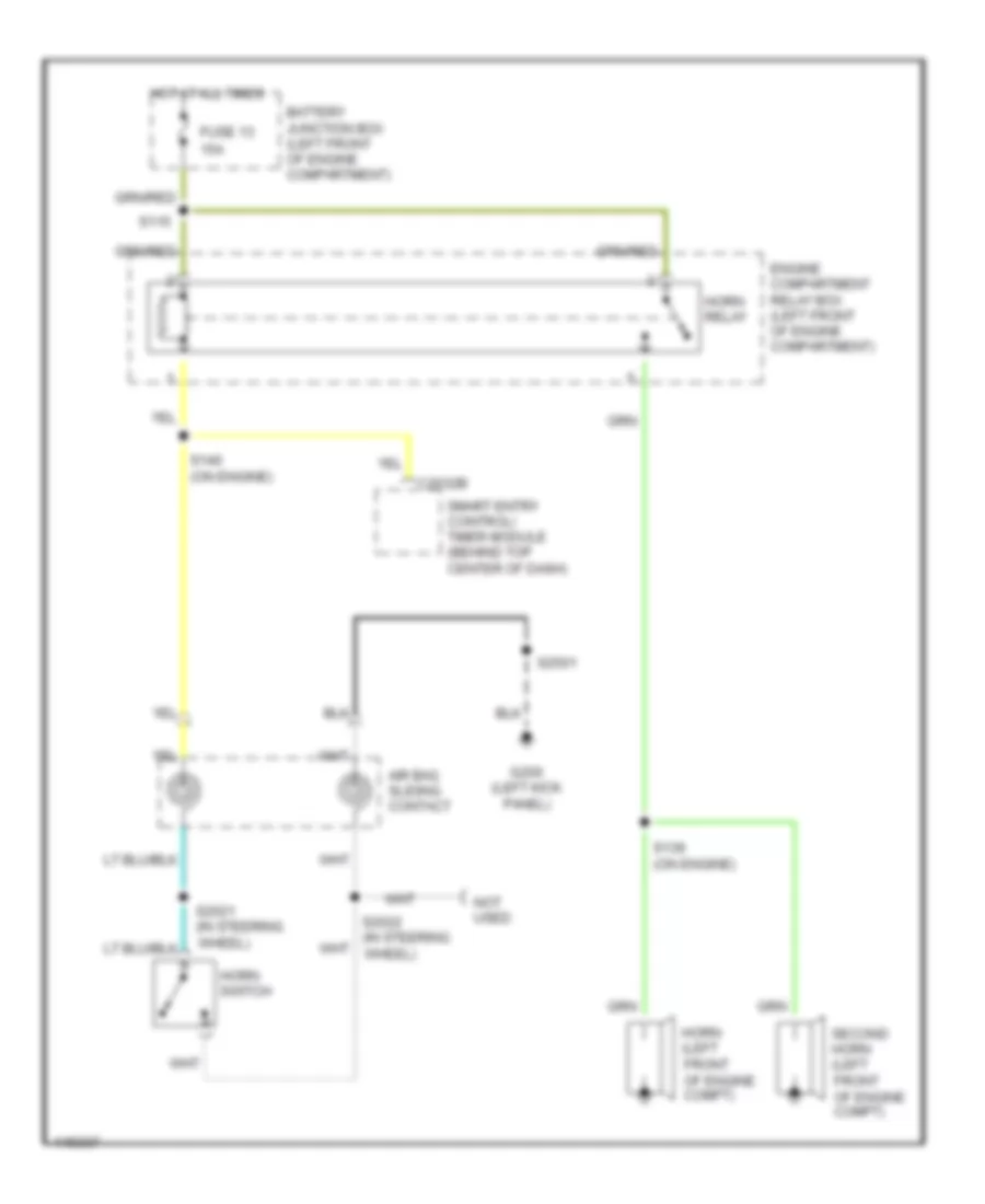
HORN
Horn Wiring Diagram for Mercury Villager Estate 2001
List of elements for Horn Wiring Diagram for Mercury Villager Estate 2001:
- 15a
- Air bag sliding contact
- Battery junction box (left front of engine compartment)
- C2032b
- Engine compartment relay box (left front of engine compartment)
- Fuse 13
- G200 (left kick panel)
- Horn (left front of engine compt)
- Horn relay
- Horn switch
- Hot at all times
- Not used
- S115
- S139 (on engine)
- S140 (on engine)
- S2021 (in steering wheel)
- S2022 (in steering wheel)
- S2501
- Second horn (left front of engine compt)
- Smart entry control/ timer module (behind top center of dash)
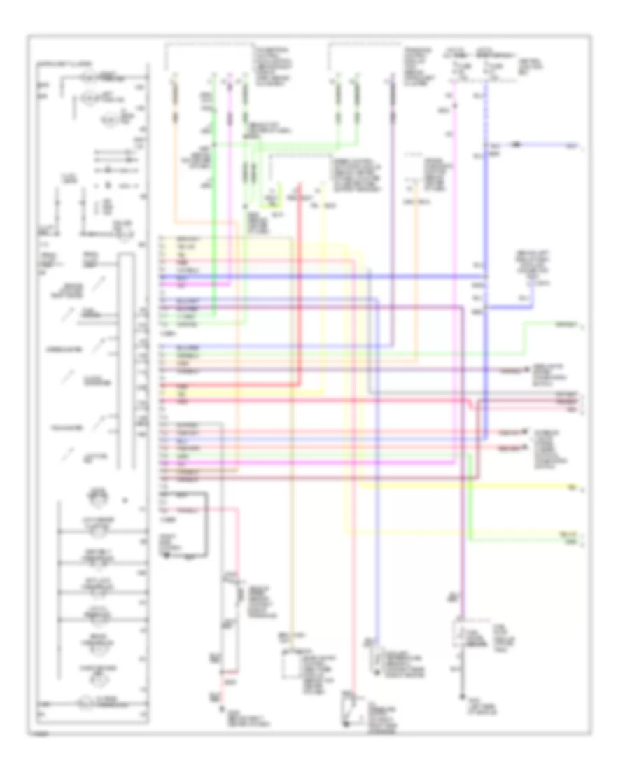
INSTRUMENT CLUSTER
Instrument Cluster Wiring Diagram, Analog Cluster (1 of 2) for Mercury Villager Estate 2001
List of elements for Instrument Cluster Wiring Diagram, Analog Cluster (1 of 2) for Mercury Villager Estate 2001:
- (behind left side of dash) data link connector (dlc)
- (behind top center of dash) s254
- (left rear of vehicle)
- (right side of dash) g201
- 10a
- 11a
- 11b
- 11c
- 12a
- 12b
- 13b
- 14b
- 15b
- 16b
- 17b
- 20b
- 22b
- Air bag diagnostic monitor (behind center of dash)
- Air bag ind.
- Anti-lock warning ind.
- Av02
- Av05
- Av32
- Brake warning ind.
- C2018
- C2032a
- C266a
- C266b
- Central junction box
- Charge warning ind.
- Check engine ind.
- Clock/ odometer
- Coolant temperature sensor 2 (on right rear side of engine)
- Cruise ind.
- Door ajar ind.
- Ej07
- Ej10
- Ej23
- Engine coolant temp. gauge
- Exterior lights system (hazard switch & combination switch)
- Fuel gauge
- Fuel gauge sender
- Fuel pump module (at fuel tank)
- Fuse 10a
- G206 (behind right center of dash)
- G404
- Gnd
- Headlights system (combination switch)
- Hi beam ind.
- Hot at all times
- Hot in start or run
- Ign
- Illum. dim
- Illum. lamps
- Instrument cluster
- Left turn ind.
- Low fuel ind.
- Low oil press. ind.
- Low washer fluid ind.
- Nr01
- Oil pressure switch (on right front side of engine)
- Pnk
- Powertrain control module (pcm) (behind right side of dash, behind glove box)
- Prndl illum. lamp
- Prndl illum. pwr
- Ps15
- Red
- Right turn ind.
- S229
- S232
- S255 (behind center of dash)
- S257 (behind top center of dash)
- S258
- S260
- S261
- S262
- Seat belt warning ind.
- Smart entry control (sec)/timer module (behind top center of dash)
- Speed control actuator module (behind center of dash, mounted on center dash support bracket)
- Speedometer
- Tachometer
- Transaxle control module (tcm) (behind instrument cluster)
- Vehicle speed sensor (on right side of transaxle)
- Zy03
- Zy24
- Zy27
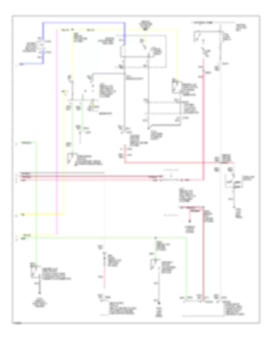
Instrument Cluster Wiring Diagram, Analog Cluster (2 of 2) for Mercury Villager Estate 2001
List of elements for Instrument Cluster Wiring Diagram, Analog Cluster (2 of 2) for Mercury Villager Estate 2001:
- (behind top center of dash) s292
- (below center of dash, mounted on center dash support brace)
- (in right front side of engine compt, on washer fluid reservoir)
- (left kick panel)
- (on brake fluid reservoir)
- Abs control module
- Abs diode (behind top left side of dash)
- Battery junction box joint connector
- Brake fluid level switch
- Bs29
- Bulb check relay
- C1000
- C2016
- C2032a
- C2032b
- C349
- Central junction box
- Engine compartment relay box
- Fuse 7.5a
- G105 (rear of right front fender)
- G116 (left rear of engine compt)
- G200
- Generator
- Head
- Headlamp switch
- Hot at all times
- Interior lights system
- J/c 2 (behind top left side of dash, right of instrument cluster)
- Jc11
- Lc45
- Lighting control module (behind center of dash)
- Of dash) s2023
- Off
- Park
- Park brake switch (on bracket, above parking brake pedal)
- Pnk
- Pr11
- Pr12
- S141 (engine compt)
- S2502
- S291 (behind top center of dash)
- S293 (behind top center of dash)
- S294 behind top center of dash)
- Sc22
- Seat belt switch (on driver's seat belt buckle)
- Smart entry control (sec)/ timer module (behind top center of dash)
- Tail- lamp relay
- Washer fluid level switch
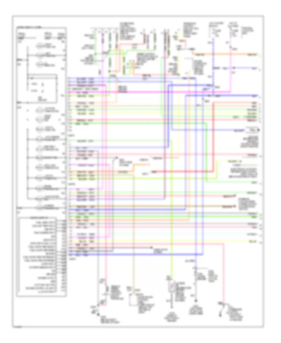
Instrument Cluster Wiring Diagram, Electronic Cluster (1 of 2) for Mercury Villager Estate 2001
List of elements for Instrument Cluster Wiring Diagram, Electronic Cluster (1 of 2) for Mercury Villager Estate 2001:
- (1999 -00)
- (1999-00)
- (2001)
- (at fuel tank)
- (behind center of dash)
- (behind top center of dash) s283
- (or red)
- 10a
- 10b
- 10c
- 11a
- 11b
- 11c
- 12a
- 12c
- 13a
- 13c
- 14a
- 14c
- 15c
- 16c
- 17c
- 18c
- 19c
- Air bag diagnostic monitor (behind center of dash)
- Air bag ind.
- All times
- Anti-lock warning ind.
- Av02
- Av05
- Av32
- Bat
- Brake warning ind.
- Bs29
- C20
- C2028a
- C2032a
- C267a
- C267b
- C267c
- Central junction box
- Charge warning ind.
- Coolant temp input
- Coolant temperature sensor 2 (on right rear side of engine)
- Cruise control on input
- Data input-fuel flow
- Digital display
- Dimmer output
- Door ajar ind.
- Ej07
- Ej08
- Ej10
- Electronic automatic temperature control (eatc) module (behind center of dash)
- Eng/met
- Exterior lights system (hazard switch & combination switch)
- Fuel computer reset
- Fuel computer select
- Fuel computer trip/reset
- Fuel computer trip/select
- Fuel gauge sender
- Fuel level input
- Fuel pump module
- Fuse 10a
- G105 (rear of right front fender)
- G201 (right side of dash)
- G206 (behind right center of dash)
- G404 (left rear of vehicle) cargo area)
- Gnd
- Grd
- Hc06
- Headlights system
- Hi beam ind.
- Hot at
- Hot in start or run
- Ig01
- Ig91
- Ig92
- Ign
- Illum dim input
- Instrument cluster
- La03
- Lb15
- Lb16
- Left turn ind.
- Low fuel ind ctrl
- Low fuel warning ind.
- Low oil level ind.
- Low oil press. ind.
- Low washer fluid ind.
- Ma01
- Ma02
- Ma03
- Ma04
- Ma06
- Ma07
- Ma11
- Ma12
- Ma14
- Ma15
- Ma16
- Ma17
- Ma41
- Mae1
- Mae2
- Malfunction ind.
- Md01
- Mj01
- Mje2
- Nb01
- Nf01
- Ni03
- Nm01
- Nn01
- Nr01
- O/d off ind.
- O/s temp sensor input
- Oil pressure switch (on right front side of engine)
- Outside air temperature sensor (behind center of front bumper)
- Pnk
- Powertrain control module (pcm) (behind right side of dash, behind glove box)
- Prndl illum. dim
- Prndl illum. lamp
- Prndl illum. pwr
- Ps15
- Red
- Right turn ind.
- S229
- S232
- S254
- S255
- S257 (behind top center of dash)
- S258
- S259
- S260
- Sc25
- Seat belt warning ind.
- Smart entry control (sec)/ timer module (behind top center of dash)
- Speed control actuator module (behind center of dash)
- Start input
- Tachometer input
- Transaxle control module (tcm) (behind instrument panel)
- Vehicle speed sensor (on right side of transaxle)
- Vss grd
- Vss input
- Vss ouput
- Zy03
- Zy24
- Zy27
- Zy34
Instrument Cluster Wiring Diagram, Electronic Cluster (2 of 2) for Mercury Villager Estate 2001
List of elements for Instrument Cluster Wiring Diagram, Electronic Cluster (2 of 2) for Mercury Villager Estate 2001:
- (2001)
- (behind center of dash) s2023
- (behind center of dash, mounted on center dash support bracket)
- (behind top center of dash) s292
- (in right front side of engine compt, on washer fluid reservoir)
- (left kick panel)
- Abs control module
- Abs diode (behind top left side of dash)
- Battery junction box
- Battery junction box joint connector
- Brake fluid level switch (on brake fluid reservoir)
- Bs29
- Bulb check relay
- C1000
- C2032a
- C2032b
- C349
- Central junction box
- Ej17
- Ejo8
- English/ metric
- Fuel computer control panel
- Fuse 7.5a
- G105 (rear of right front fender)
- G116 (left rear of engine compt)
- G200
- G200 (left kick panel)
- Generator
- Head
- Headlamp switch
- Hot at all times
- Illum.
- Interior lights system (instrument illumination)
- J/c 2 (behind top left side of dash, right of instrument cluster)
- Lighting control module (behind center of dash)
- Of dash)
- Off
- Park
- Park brake switch (on bracket, above parking brake pedal)
- Pnk
- Pr11
- Red
- Reset
- S141 (engine compt)
- S2502
- S253 (behind dash)
- S291 (behind top center of dash)
- S294 (behind top center of dash)
- Seat belt switch (on driver's seat belt buckle)
- Select
- Smart entry control (sec)/ timer module (behind top center of dash)
- Speed control actuator module (behind center of dash) (2001)
- Tail lamp relay
- Trip reset
- Trip select
- Washer fluid level switch
INTERIOR LIGHTS
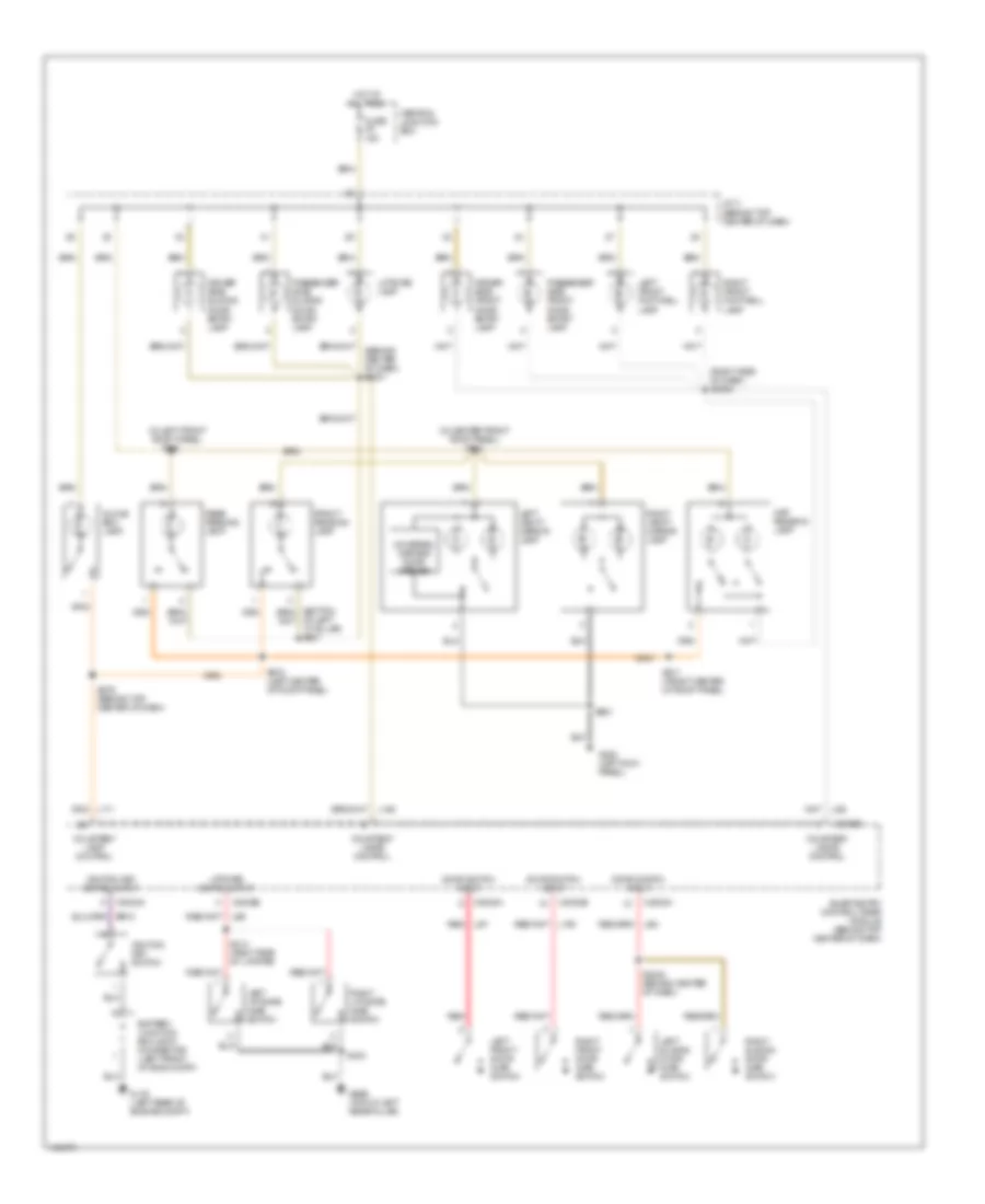
Courtesy Lamps Wiring Diagram, with Reading Lights for Mercury Villager Estate 2001
List of elements for Courtesy Lamps Wiring Diagram, with Reading Lights for Mercury Villager Estate 2001:
- (behind center of dash) s2001
- (in center front roof panel) s912
- (in left front roof panel)
- (right side of dash) s2000
- Battery junction box joint connector (left front of eng compt)
- C2032a
- C2032b
- Central junction box
- Courtesy lamp control
- Courtesy lamps control
- Door switch input
- Driver side front door entry lamp
- Driver side sliding door entry lamp
- Front reading lamp
- Fuse 15a
- G116 (left rear of engine compt)
- G200 (left kick panel)
- G999 (top of left rear pillar)
- Glove box lamp
- Hot at all times
- Ignition key switch
- Ignition key switch input
- J/c 3 (behind top center of dash)
- L192
- Left front footwell lamp
- Left front door ajar switch
- Left liftgate ajar switch
- Left sliding door ajar switch
- Left vanity mirror lamp
- Li92
- Liftgate lamp
- Liftgate switch input
- Map reading lamp
- Of left "a" pillar) s907
- Passenger side front door entry lamp
- Passenger side sliding door entry lamp
- Rear reading lamp
- Red
- Red li87
- Right front door ajar switch
- Right front footwell lamp
- Right liftgate ajar switch
- Right sliding door ajar switch
- Right vanity mirror lamp
- S2040 (behind center of dash)
- S276 (behind top center of dash)
- S403
- S414 (right side of lifgate)
- S901
- S910
- S911 (front center of roof panel)
- S915 (left center of roof panel)
- Smart entry control/timer module (behind top center of dash)
- Universal garage door opener
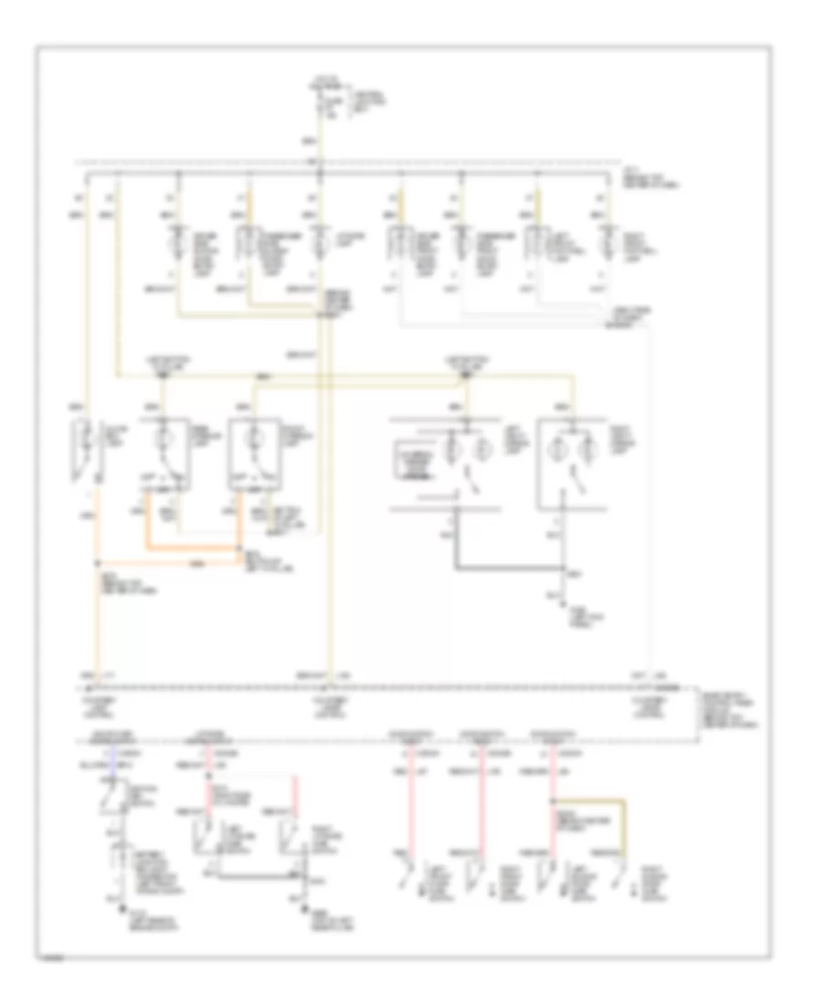
Courtesy Lamps Wiring Diagram, without Reading Lights for Mercury Villager Estate 2001
List of elements for Courtesy Lamps Wiring Diagram, without Reading Lights for Mercury Villager Estate 2001:
- (behind center of dash) s2001
- (left bottom "a" pillar)
- (left bottom "a" pillar) s904
- (right side of dash) s2000
- Battery junction box joint connector (left front of eng compt)
- C2032a
- C2032b
- Central junction box
- Courtesy lamp control
- Courtesy lamps control
- Door switch input
- Driver side front door entry lamp
- Driver side sliding door entry lamp
- Front interior lamp
- Fuse 15a
- G116 (left rear of engine compt)
- G200 (left kick panel)
- G999 (top of left rear pillar)
- Glove box lamp
- Hot at all times
- Ignition key switch
- Ignition key switch input
- J/c 3 (behind top center of dash)
- L192
- Left front footwell lamp
- Left front door ajar switch
- Left liftgate ajar switch
- Left sliding door ajar switch
- Left vanity mirror lamp
- Li92
- Liftgate lamp
- Liftgate switch input
- Of left "a" pillar) s917
- Off
- Passenger side front door entry lamp
- Passenger side sliding door entry lamp
- Rear interior lamp
- Red
- Red li87
- Right front door ajar switch
- Right front footwell lamp
- Right liftgate ajar switch
- Right sliding door ajar switch
- Right vanity mirror lamp
- S2040 (behind center of dash)
- S276 (behind top center of dash)
- S403
- S414 (right side of lifgate)
- S901
- S902
- S916 (bottom of left "a" pillar)
- Smart entry control/timer module (behind top center of dash)
- Universal garage door opener
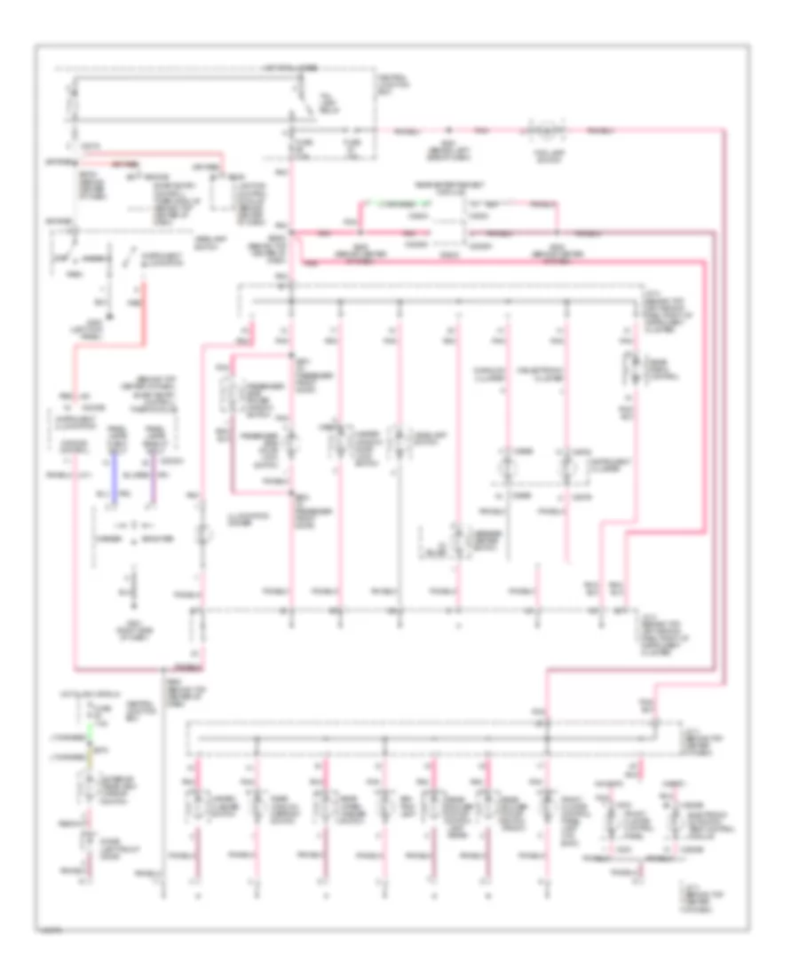
Instrument Illumination Wiring Diagram for Mercury Villager Estate 2001
List of elements for Instrument Illumination Wiring Diagram for Mercury Villager Estate 2001:
- (2) bulbs
- (behind top center of dash)
- (or 4)
- Ash- tray lamp
- Brighter
- C2016
- C2026a
- C2028b
- C203
- C2032a
- C2032b
- C266b
- C267b
- C267c
- C349
- C393a
- Central junction box
- Darker
- Dimming control
- Diode (left front door)
- Electronic automatic temp control module
- Exterior rear view mirror switch
- Fog lamp switch
- Front climate control panel
- Front climate control panel lamp (w/o eatc)
- Fuse 10a
- Fuse 7.5a
- G200 (left kick panel)
- G201 (right side of dash)
- Hazard flasher switch
- Head
- Headlamp switch
- Hot at all times
- Hot in acc or run
- Illumination dimmer
- Instrument cluster
- Instrument illumination
- Ip02
- J/c 2 (behind top left side of dash, right of instrument cluster)
- J/c 3 (behind top center of dash)
- Lighting control module (behind center of dash)
- Master window/ door lock switch
- Message center switch
- Off
- Panel lamps "bright" input
- Panel lamps "dark" input
- Park
- Passenger side door lock switch
- Passenger side power window switch
- Pnk
- Radio
- Rear blower motor switch (front)
- Rear blower motor switch lamp (rear)
- Rear entertainment module
- Rear radio control
- Rear window defrost switch
- Rear wiper/ washer switch
- Red
- Red li40
- S202 (behind center of dash)
- S2023 (behind center of dash)
- S209 (behind center of dash)
- S2502 (behind top center of dash)
- S251 (behind left side of dash)
- S279
- S294 (behind top center of dash)
- S601 (in passenger front door)
- S602 (in passenger front door)
- Smart entry control/ timer module
- Smart entry control/ timer module (behind top center of dash)
- Tail lamp relay
- W/analog cluster
- W/eatc
- W/electronic cluster
- W/o eatc
MEMORY SYSTEMS
Memory Mirrors Wiring Diagram for Mercury Villager Estate 2001
List of elements for Memory Mirrors Wiring Diagram for Mercury Villager Estate 2001:
- (left kick panel) g200
- (left rear of vehicle) g404
- (top of pass door) s2044
- Battery junction box
- C2032a
- C2032b
- C502a
- C502b
- C614a
- C614b
- Central junction box
- Circuit breaker 2 (behind left side of dash)
- Defogger system
- Direct- tional switch
- Driver seat module (under driver seat)
- Exterior rear view mirror switch
- Fuse 10a
- Fuse 15a
- Fuse 30a
- Fuse 7.5a
- Heated mirror
- Hot at all times
- Hot in run or accy
- Hot in run or start
- Interior lights system
- J/c 3 (behind top center of dash)
- Ka11
- Ka12
- Ka22
- Ka24
- Ka25
- Ka26
- Ka27
- Ka28
- Ka29
- Ka30
- Ka31
- Ka32
- Ka33
- Ka34
- Ka35
- Ka36
- Ka40
- Ka41
- Ka55
- Kae7
- Left exterior rear view mirror
- Left/ right
- Left/right mirror select switch
- Memory seats system
- Memory set switch
- Nca
- Pnk
- Right exterior rear view mirror
- S2029
- S2041 (top of driver door)
- S2042 (top of driver door)
- S2043 (behind left side of dash)
- S2045 (top of pass door)
- S2046 (behind left side of dash)
- S2047 (behind left side of dash)
- S2048 (behind left side of dash)
- S226
- S228
- S237
- S2500
- S279
- S501
- S512
- Sb01
- Sb04
- Sb06
- Sbe3
- Sbe4
- Set
- Smart entry control (sec)/ timer module (behind top center of dash)
- Transmissions system
- Up/ down
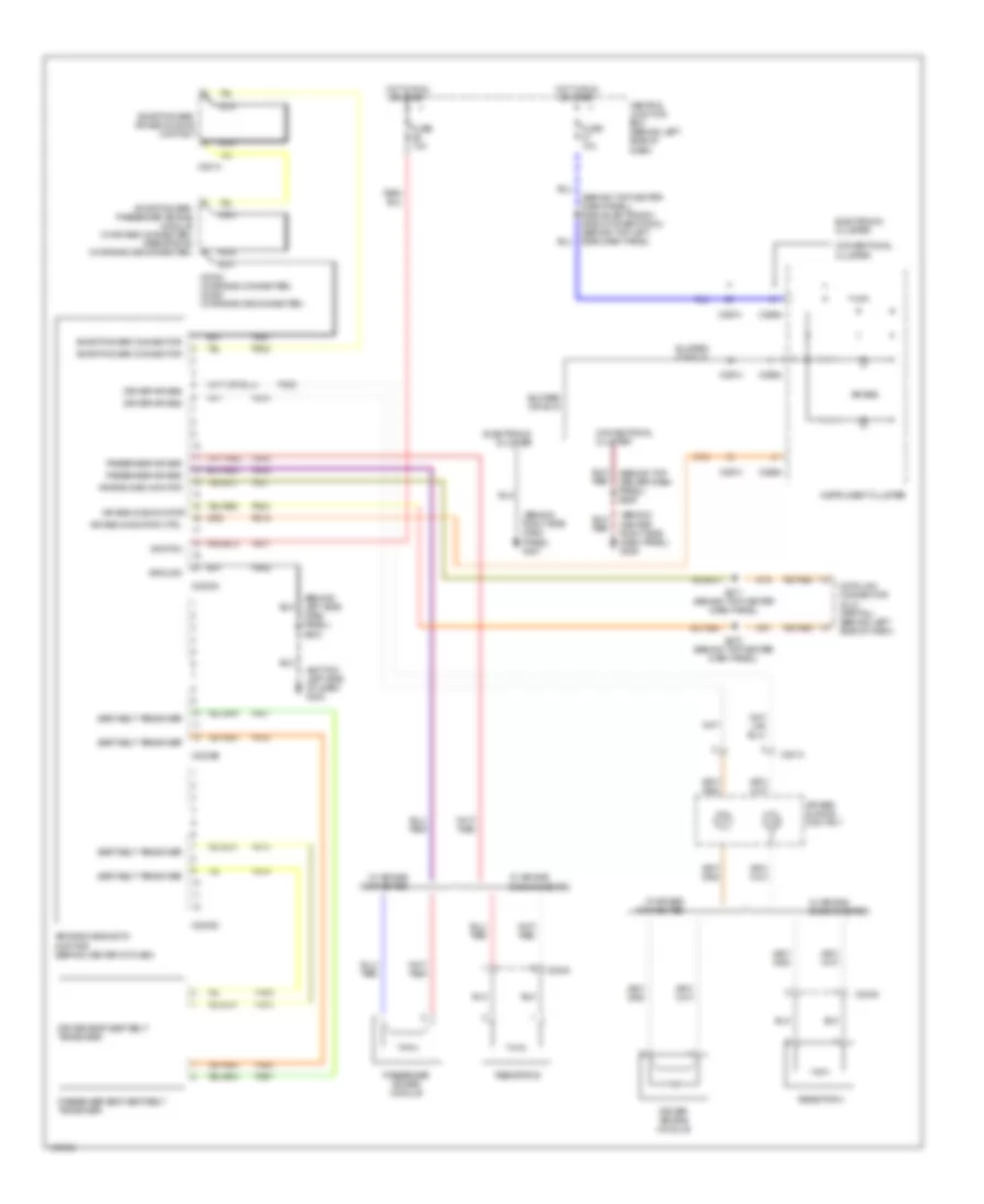
Memory Seat Wiring Diagram for Mercury Villager Estate 2001
List of elements for Memory Seat Wiring Diagram for Mercury Villager Estate 2001:
- (left kick panel) g200
- (left rear of vehicle) g404
- Backrest forward/ rearward
- Backrest forward/ rearward sensor
- Backrest switch
- Battery junction box
- C2032b
- C357
- Central junction box
- Circuit breaker 2 (behind left side of dash)
- Down
- Driver seat module (under driver seat)
- Forward
- Fuse 10a
- Fuse 15a
- Fuse 30a
- Height switch
- Hot at all times
- Hot in run or start
- J/c 3 (behind top center of dash)
- Ka11
- Ka12
- Ka22
- Ka24
- Ka25
- Ka26
- Ka27
- Ka28
- Ka29
- Ka30
- Ka31
- Ka32
- Ka33
- Ka34
- Ka35
- Ka36
- Ka40
- Ka41
- Ka55
- Kae7
- Left power seat motor assembly (on underside of left front seat)
- Left power seat switch
- Memory mirrors system
- Memory set switch
- Nca
- Pnk
- Rearward
- Rest
- S2029
- S2030 (driver seat)
- S2031 (driver seat)
- S2032 (driver seat)
- S226
- S228
- S237
- S2500
- S501
- Sb01
- Sb04
- Sb06
- Sbe3
- Sbe4
- Seat forward/ rearward
- Seat forward/ rearward sensor
- Seat height up/ down sensor
- Seat switch
- Seat up/ down
- Set
- Smart entry control (sec)/ timer module (behind top center of dash)
- Transmissions system
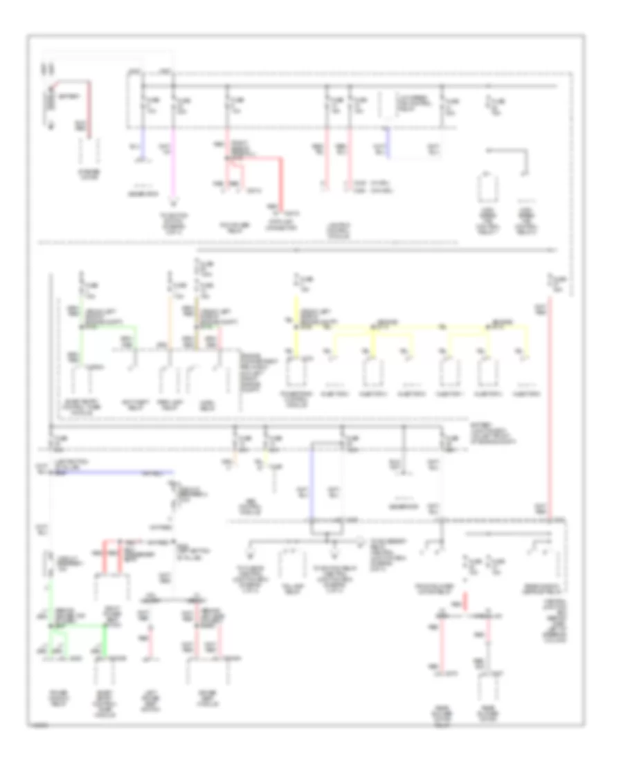
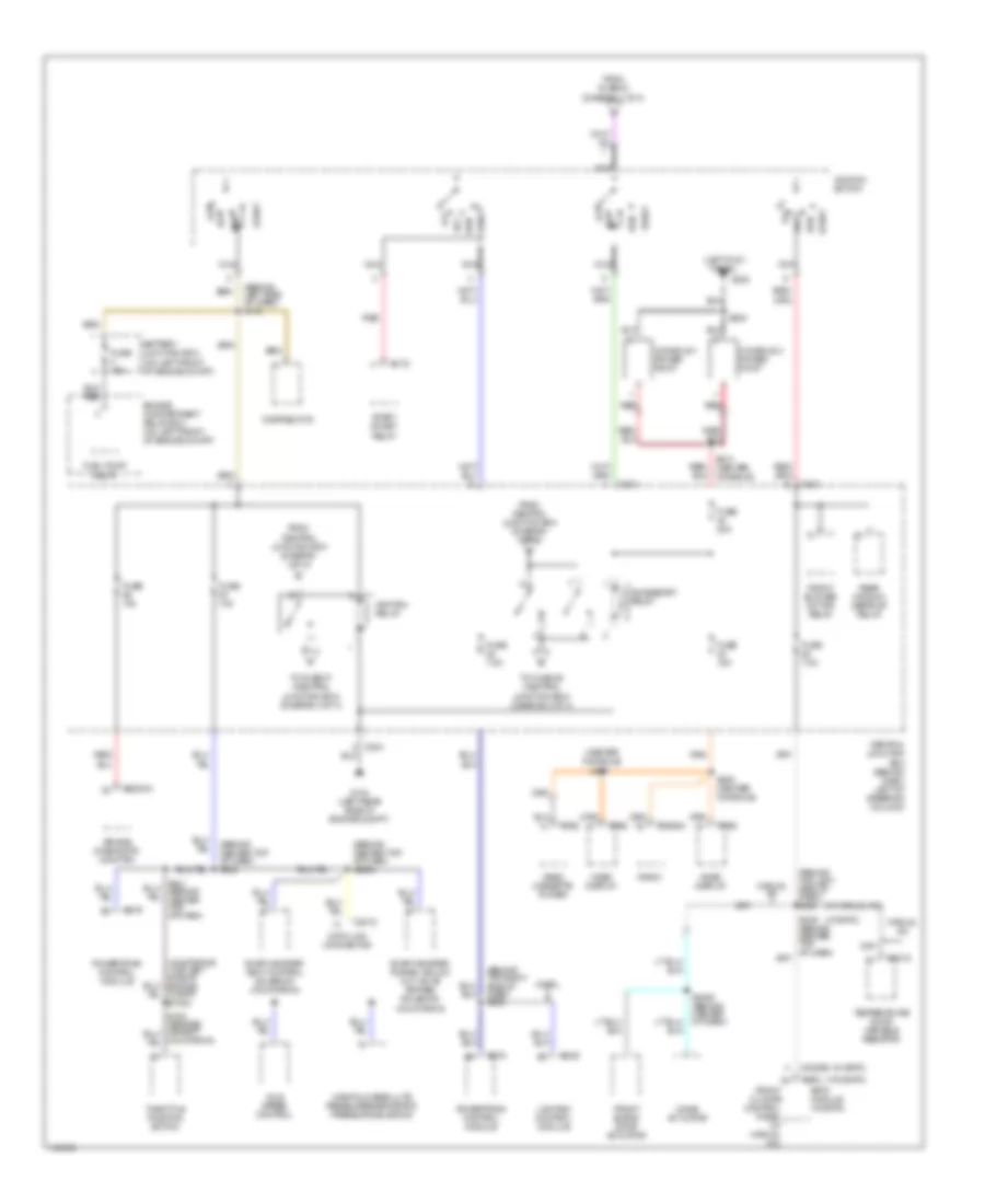
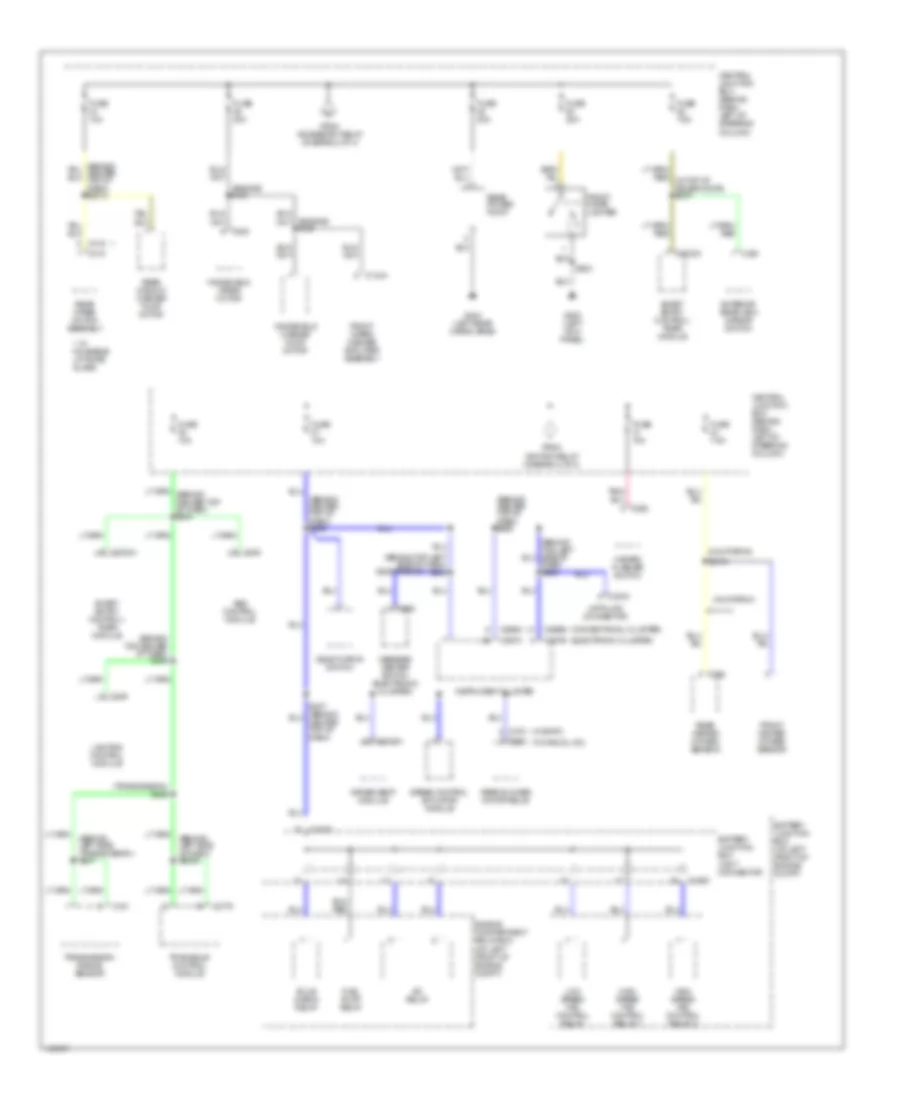
POWER DISTRIBUTION
Power Distribution Wiring Diagram (1 of 4) for Mercury Villager Estate 2001
List of elements for Power Distribution Wiring Diagram (1 of 4) for Mercury Villager Estate 2001:
- "b" pillar)
- (behind center top of dash) s227
- (behind left side of dash) s2500
- (engine) s114
- (engine) s118
- (front left side of engine compt) s115
- (front left side of engine compt) s129
- (front left side of engine compt) s133
- (left bottom "b" pillar) s226
- (right side of firewall) s112
- (w/ drl)
- (w/o drl)
- Abs control module
- Anti-theft relay
- Battery
- Battery junction box (on left front of engine compt)
- C2012
- C2018
- C202
- C2032a
- C2032b
- C2046a
- C206
- C228
- C249
- C275
- C337
- C349
- C350
- C370
- Central junction box (behind dash, left of steering column)
- Circuit breaker 1 18a
- Circuit breaker 2 18a
- Data link connector
- Driver seat module
- Engine compartment relay box (on left front engine compt)
- Front blower motor relay
- Fuse 100a
- Fuse 10a
- Fuse 140a
- Fuse 15a
- Fuse 20a
- Fuse 30a
- Fuse 40a
- Fuse 45a
- Fuse 65a
- Fuse 7.5a
- Fuse 75a
- Generator
- High speed fan control relay 1
- High speed fan control relay 2
- Horn relay
- Injector 1
- Injector 2
- Injector 3
- Injector 4
- Injector 5
- Injector 6
- Left power seat switch
- Lighting control module
- Low speed fan control relay
- Park lamp relay
- Pcm power relay
- Power window relay
- Powertrain control module
- Rear blower motor
- Rear blower motor relay
- Rear window defrost relay
- Red
- Right power seat switch
- S228 (left bottom
- S341 (passenger seat)
- Smart entry control timer module
- Smart entry control/ timer module
- Starter motor
- Taillamp relay
- To accessory relay (central junction box) (diagram 2 of 4)
- To fuse 55 (central junction box) (diagram 4 of 4)
- To ignition relay (central junction box) (diagram 2 of 4)
- To ignition switch (diagram 2 of 4)
- W/ eatc
- W/ manual a/c
- W/ memory
- W/o memory
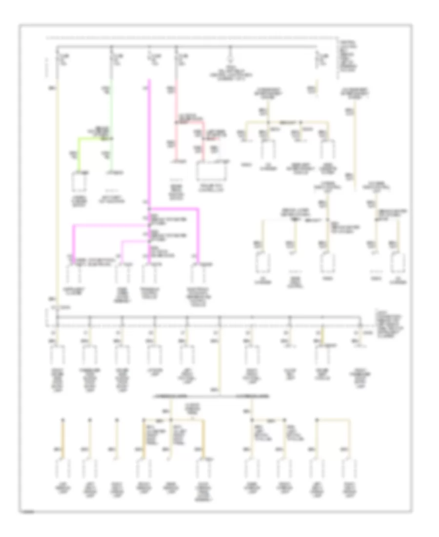
Power Distribution Wiring Diagram (2 of 4) for Mercury Villager Estate 2001
List of elements for Power Distribution Wiring Diagram (2 of 4) for Mercury Villager Estate 2001:
- (behind center top of dash) s2024
- (behind center top of dash) s242
- (behind left side of dash) s119
- (behind top left side of dash) s250
- (behind top right side of dash) s238
- (center console)
- (left kick panel)
- (w/ eatc)
- (w/ manual a/c)
- (w/o eatc)
- Acc
- Accessory relay
- Air bag diagnostic monitor
- Battery junction box (on left front of engine compt)
- C178
- C2003a
- C2015
- C2018
- C2026a
- C2028b
- C203
- C204
- C275
- C349
- C392
- C395
- Central junction box (behind dash, left of steering column)
- Console 1 power point
- Console 2 power point
- Data link connector
- Distributor
- Eatc module (w/ eatc)
- Engine compartment relay box (on left front of engine compt)
- Evap canister purge vacuum cut valve bypass solenoid (california)
- Evap canister vent control solenoid (california)
- From central junction box (diagram 1 of 4)
- From fuse 23 (diagram 1 of 4)
- Front blend door actuator
- Front blower motor relay
- Front climate control panel (w/ manual a/c)
- Fuel pump relay
- Fuse 10a
- Fuse 15a
- Fuse 20a
- Fuse 7.5a
- G104 (left rear side of engine compt)
- G200
- Idle speed control
- Ignition relay
- Ignition switch
- Lighting control module
- Manifold absolute pressure/barometric pressure solenoid
- Manual a/c
- Mode actuator
- Nca
- Off
- Powertrain control module
- Radio
- Rear window defrost relay
- Red
- Run
- S1002
- S205 (center console)
- S2050 (behind center of dash)
- S207
- S208
- S210 (center console)
- Start
- Start inhibit relay
- Temperature door variable resistor
- Throttle position switch
- To fuse 37 (central junction box) (diagram 3 of 4)
- To fuse 46 (central junction box) (diagram 3 of 4)
- Video cassette player
- Video display
- W/drl
Power Distribution Wiring Diagram (3 of 4) for Mercury Villager Estate 2001
List of elements for Power Distribution Wiring Diagram (3 of 4) for Mercury Villager Estate 2001:
- (behind center top of dash) s258
- (behind center top of dash) s260
- (behind left side (transmission) s247
- (behind left side of dash) s2035
- (behind top center of dash) s245
- (behind top left side of dash) s259
- (behind top left side of dash) s262
- (california)
- (conventional cluster)
- (electronic cluster)
- (electronic)
- (engine) s127
- (engine) s160
- (transmission) s246
- (w/ eatc)
- (w/ manual a/c)
- 1 w/ moveable liftgate glass
- A/c relay
- Abs control module
- Battery junction box (on left front of engine compt)
- Battery junction box joint connector
- Bulb check relay
- C1000
- C134a
- C161
- C200
- C2018
- C2032a
- C2046a
- C249
- C254
- C264
- C266a
- C266b
- C267b
- C267c
- C268
- C277a
- C292
- C349
- C365
- C370
- C418
- C419
- California
- Central junction box (behind dash, left of steering column)
- Data link connector
- Deactivator switch
- Driver seat module
- Engine compartment relay box (on left front of engine compt)
- Exterior rear view mirror switch
- From accessory relay (diagram 2 of 4)
- From ignition relay (diagram 2 of 4)
- Front cigar lighter
- Front heated oxygen sensor
- Front wiper/ washer amplifier assembly
- Fuel pump relay
- Fuse 10a
- Fuse 20a
- Fuse 7.5a
- G200 (left kick panel)
- G404 (left rear cargo area)
- Hazard flasher switch
- High speed fan control relay 1
- High speed fan control relay 2
- Instrument cluster
- Lighting control module
- Low speed fan control relay
- Message center switch (electronic cluster)
- Rear blower motor relay
- Rear heated oxygen sensor
- Rear power point
- Rear window washer pump motor
- Rear wiper motor assembly
- S203
- S2104
- Smart entry control/ timer module
- Speed control actuator module
- Transaxle control module
- Transmission range sensor
- Windshield washer pump motor
- Windshield wiper motor
Power Distribution Wiring Diagram (4 of 4) for Mercury Villager Estate 2001
List of elements for Power Distribution Wiring Diagram (4 of 4) for Mercury Villager Estate 2001:
- (behind center top of dash) s2105
- (behind lower center of dash)
- (behind top center of dash) s240
- (conventional)
- (electronic)
- (in top of driver door) s239
- Anti-theft "on" indicator
- Brake pedal position switch
- C2020
- C2028b
- C2040
- C2046a
- C267a
- C277b
- C280
- C292
- C361
- C419
- C914
- Cd changer
- Central junction box (behind dash, left of steering column)
- Driver seat module
- Driver side sliding door entry lamp
- Electronic automatic temperature control module
- From taillamp relay (central junction box) (diagram 1 of 4)
- Front driver side door entry lamp
- Front interior lamp
- Front passenger door entry lamp
- Front reading lamp
- Fuse 10a
- Fuse 15a
- Fuse 20a
- Glove box lamp
- Hazard flasher switch
- Instrument cluster
- Joint connector 3 (behind top left side of dash, right of instrument cluster)
- Left front footwell lamp
- Left vanity mirror lamp
- Liftgate lamp
- Map reading lamp
- Passenger side sliding door entry lamp
- Radio
- Rear interior lamp
- Rear radio control
- Rear reading lamp
- Rear seat entertainment module
- Rear wiper motor assembly
- Right front footwell lamp
- Right vanity mirror lamp
- Roof opening panel motor assembly
- S2034
- S234 (behind center top of dash)
- S312
- S902 (left bottom "a" pillar)
- S904 (left bottom "a" pillar)
- S910 (in left front roof panel)
- S912 (in center front roof panel)
- Trailer tow control unit
- Transaxle control module
- Video cassette player
- W/ interior lamps
- W/ reading lamps
- W/ rear radio control unit
- W/ rear seat entertainment system
- W/ roof opening panel
- W/o rear radio control unit
- W/o rear seat entertainment system
POWER DOOR LOCKS
Power Door Lock Wiring Diagram (1 of 2) for Mercury Villager Estate 2001
List of elements for Power Door Lock Wiring Diagram (1 of 2) for Mercury Villager Estate 2001:
- (1999, 2000)
- (behind top center of dash)
- (left front of engine compt) engine compartment relay box
- (left rear of engine compt) g116
- (right side of dash) g201
- 20a
- Anti- theft 'on' indicator
- Anti-theft relay
- Battery junction box (on left front of engine compt)
- Battery junction box joint connector
- C2032a
- C2032b
- C242
- Central junction box (behind left side of dash)
- Circuit breaker 1 (behind left side of dash)
- Engine compartment switch (1999, 2000)
- Er05
- Er10
- Front power windows only
- Full power windows
- Fuse 35 10a
- Fuse 4 7.5a
- Fuse 49 10a
- Fuse 52 7.5a
- G105 (rear of right front fender)
- G200 (left kick panel)
- G201 (right side of dash)
- G999 (top of left rear pillar)
- Horns system
- Hot at all times
- Hot in run or accy
- Hot in run or start
- Ignition key switch
- Interior lights system
- Left front door ajar switch
- Left liftgate ajar switch
- Left sliding door ajar switch
- Li87
- Li89
- Li90
- Li94
- Lock
- Master window/ door lock/ unlock switch
- Passenger window/ door lock/ unlock switch
- Ph10
- Ph19
- Ph35
- Ph38
- Ph43
- Pnk
- Ps95
- Red
- Right front door ajar switch
- Right liftgate ajar switch
- Right sliding door ajar switch
- S133
- S2040 (behind center of dash)
- S206
- S227
- S240
- S244
- S267
- S268
- S279
- S403
- S414 (right side of liftgate)
- S501
- S600
- Sc06
- Sc09
- Sc11
- Sc13
- Sc14
- Sc15
- Sc16
- Sc18
- Sc21
- Sc24
- Sce1
- Sce2
- Sce3
- Smart entry control (sec)/ timer module (behind top center of dash)
- St70
- St96
- Starting/ charging system
- Unlk
Power Door Lock Wiring Diagram (2 of 2) for Mercury Villager Estate 2001
List of elements for Power Door Lock Wiring Diagram (2 of 2) for Mercury Villager Estate 2001:
- (behind center of dash) s2049
- (left rear of vehicle) s330
- (left rear of vehicle) s331
- (left side of sliding door) s307
- (right side of sliding door) s308
- Driver side door lock actuator assembly
- Driver side key lock switch
- G200 (left kick panel)
- G201 (right side of dash)
- G999 (top of left rear pillar)
- Left sliding door lock actuator assembly
- Liftgate key lock switch
- Liftgate lock actuator assembly
- Lock
- Nca
- Passenger side door lock actuator assembly
- Passenger side key lock switch
- Red
- Right sliding door lock actuator assembly
- S2503 (behind center of dash)
- S274 (behind top center of dash)
- S275 (behind top center of dash)
- S303 (behind center top of dash)
- S332 (left rear of vehicle)
- S403
- S404
- S501
- S600
- Sliding door contact assemblies
- Unlk
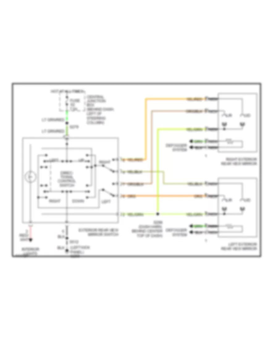
POWER MIRRORS
Power Mirror Wiring Diagram for Mercury Villager Estate 2001
List of elements for Power Mirror Wiring Diagram for Mercury Villager Estate 2001:
- (left kick panel) g200
- Central junction box (behind dash, left of steering column)
- Defogger system
- Direc- tional control switch
- Down
- Exterior rear view mirror switch
- Fuse 7.5a
- Hot at all times
- Interior lights
- L/r
- Left
- Left exterior rear view mirror
- Nca
- Right
- Right exterior rear view mirror
- S279
- S298 (dash harn, behind center top of dash)
- S512
- U/d
POWER SEATS
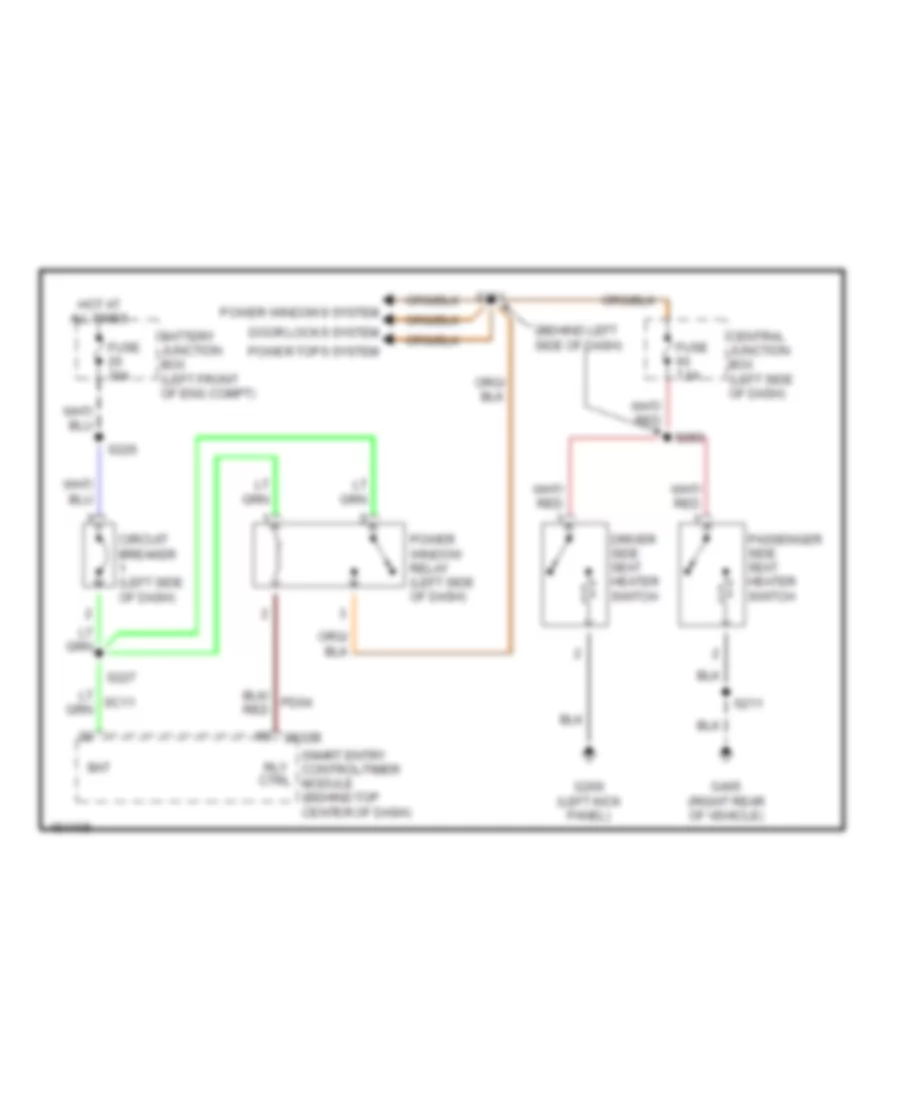
Heated Seats Wiring Diagram for Mercury Villager Estate 2001
List of elements for Heated Seats Wiring Diagram for Mercury Villager Estate 2001:
- (behind left side of dash)
- 2032b
- Bat
- Battery junction box (left front of eng compt)
- Central junction box (left side of dash)
- Circuit breaker (left side of dash)
- Door locks system
- Driver side seat heater switch
- Fuse 30a
- Fuse 7.5a
- G200 (left kick panel)
- G405 (right rear of vehicle)
- Hot at all times
- Passenger side seat heater switch
- Power tops system
- Power window relay (left side of dash)
- Power windows system
- Rly ctrl
- S211
- S226
- S227
- S261
- S283
- Smart entry control/timer module (behind top center of dash)
Power Seat Wiring Diagrams for Mercury Villager Estate 2001
List of elements for Power Seat Wiring Diagrams for Mercury Villager Estate 2001:
- Battery junction box
- Circuit breaker 2 (behind left side of dash)
- Fuse 30a
- Fwd rwd
- Fwd/ rev motor
- G200 (left kick panel)
- G405 (right rear of vehicle)
- Hot at all times
- Left power seat motor assembly
- Left power seat switch
- Nca
- Pnk
- Recline motor
- Recline switch
- Red
- Right power seat motor assembly
- Right power seat switch
- S226
- S228
- S319
- S341
- Up dn
- Up/dn motor
POWER TOP/SUNROOF
Power Top/Sunroof Wiring Diagrams for Mercury Villager Estate 2001
List of elements for Power Top/Sunroof Wiring Diagrams for Mercury Villager Estate 2001:
- (1999, 2000)
- (2001)
- (dash harn,
- (dash harn, behind center top of dash)
- (roof harn, center of headliner)
- Battery junction box (left front of engine compt)
- Behind center top of dash)
- C2032b
- C288
- C910
- C914
- Central junction box (behind left side of dash)
- Circuit breaker 1 18a (behind left side of dash)
- Fuse 15a
- Fuse 30a
- G200 (left kick panel)
- Hot at all times
- Interior lighting
- Open/ down
- Power window relay (behind left
- Power windows
- Roof opening panel motor assembly (center of headliner)
- Roof opening panel switch (center of headliner)
- S226
- S227
- S261
- S276
- S299 (dash harn, behind (dash harn, behind left right side of dash)
- S910
- S911
- S915
- Side of dash)
- Smart entry control/ timer module (behind top center of dash)
- Up/ close
POWER WINDOWS
Power Window Wiring Diagram for Mercury Villager Estate 2001
List of elements for Power Window Wiring Diagram for Mercury Villager Estate 2001:
- (2001) (2000)
- (behind left side of dash) s261 s299 (behind right side of dash)
- (w/ rear power windows) (w/o rear power windows)
- (w/o rear power windows) (w/ rear power windows)
- C2032
- Circuit breaker 1 (behind left side of dash)
- Closed
- Front driver side power window motor
- Front passenger side power window motor
- G200 (left kick panel)
- Hot at all times
- Interior lights system
- Left rear power window motor
- Master window/ door lock/ unlock switch
- Open
- Passenger side power window switch
- Pd04
- Pnk
- Power tops system
- Power window relay (behind left side of dash)
- Red
- Right rear power window motor
- S227
- S501
- Sc11
- Smart entry control/timer module (behind top center of dash)
- Solid state
RADIO
Radio Wiring Diagrams, Base for Mercury Villager Estate 2001
List of elements for Radio Wiring Diagrams, Base for Mercury Villager Estate 2001:
- Air bag sliding contact
- Antenna
- Audio network
- Audio on
- Audio system on
- C2026a
- C2026b
- C237
- Cd changer
- Cd left sig in
- Cd left sig out
- Cd player shield
- Cd right sig in
- Cd right sig out
- Central junction box (behind left side of dash)
- Down
- Fuse 10a
- Fuse 15a
- Fused ignition
- G206 (behind right center of dash)
- Ground
- Hot at all times
- Hot in run or acc
- Illum feed
- Illum return
- Interior lights
- L front spkr
- L rear spkr
- Left front speaker
- Left rear speaker
- Left sig (+)
- Left sig (-)
- Lf01
- Lf91
- Nca
- Next
- Pnk
- Power
- R front spkr
- R rear spkr
- Ra01
- Ra03
- Ra50
- Ra51
- Ra52
- Ra53
- Ra54
- Ra55
- Ra56
- Ra57
- Radio
- Radio control
- Rb06
- Rb07
- Rb19
- Rb20
- Rb25
- Rb27
- Rb61
- Rb62
- Rb63
- Rb64
- Rb95
- Rbe1
- Rbe6
- Rbe7
- Red
- Right front speaker
- Right rear speaker
- Right sig (+)
- Right sig (-)
- S2033
- S205
- S2105
- Shield
- Steering wheel radio switch
Radio Wiring Diagrams, Midline for Mercury Villager Estate 2001
List of elements for Radio Wiring Diagrams, Midline for Mercury Villager Estate 2001:
- (behind center of dash)
- (left kick panel)
- (left side of engine compt)
- Air bag sliding contact
- Antenna
- Audio joint connector
- Audio network
- Audio on
- Audio system on
- C2026a
- C2026b
- C237
- C320
- Cd changer
- Cd left sig in
- Cd left sig out
- Cd player shield
- Cd right sig in
- Cd right sig out
- Central junction box (behind left side of dash)
- Down
- Fuse 10a
- Fuse 15a
- Fused ignition
- G200
- G206 (behind right center of dash)
- Ground
- Hot at all times
- Hot in run or acc
- Illlum feed
- Illum feed
- Illum return
- Interior lights
- L front spkr
- L rear spkr
- Left front speaker
- Left rear speaker
- Left sig (+)
- Left sig (-)
- Lf01
- Lf04
- Lf91
- Lf94
- Nca
- Next
- Pnk
- Power
- Protocol a
- R front spkr
- R rear spkr
- Ra01
- Ra03
- Ra12
- Ra21
- Ra44
- Ra45
- Ra46
- Ra47
- Ra50
- Ra51
- Ra52
- Ra53
- Radio
- Radio control
- Rb03
- Rb04
- Rb06
- Rb07
- Rb11
- Rb15
- Rb19
- Rb20
- Rb23
- Rb24
- Rb25
- Rb27
- Rb35
- Rb36
- Rb37
- Rb50
- Rb95
- Rbe1
- Rbe2
- Rbe6
- Rbe7
- Rear radio control
- Red
- Right front speaker
- Right rear speaker
- Right sig (+)
- Right sig (-)
- S2006
- S2007
- S2008
- S2033
- S2034
- S205
- S234
- Shield
- Steering wheel radio switch
Radio Wiring Diagrams, Premium Radio with Rear Entertainment Center (1 of 2) for Mercury Villager Estate 2001
List of elements for Radio Wiring Diagrams, Premium Radio with Rear Entertainment Center (1 of 2) for Mercury Villager Estate 2001:
- (behind center of dash)
- (left side of engine compt)
- Air bag sliding contact
- Antenna
- Audio network
- Audio on
- Audio shield
- Audio system on
- C2026a
- C2026b
- C2026c
- C237
- C353
- C388
- Cd changer
- Cd left sig in
- Cd left sig out
- Cd player shield
- Cd right sig in
- Cd right sig out
- Central junction box (behind left side of dash)
- Down
- Fuse 10a
- Fuse 15a
- Fused ignition
- G206 (behind right center of dash)
- G404 (left rear of vehicle)
- Ground
- High audio mute
- Hot at all times
- Hot in run or acc
- Illum feed
- Illum return
- Interior lights system
- L front spkr
- L rear spkr
- Left front speaker
- Left front tweeter
- Left sig (+)
- Left sig (-)
- Lf01
- Lf91
- Nca
- Next
- Pnk
- Power
- R front spkr
- R rear spkr
- Ra01
- Ra03
- Ra40
- Ra41
- Ra42
- Ra43
- Ra44
- Ra45
- Ra46
- Ra47
- Radio
- Radio control
- Rb03
- Rb04
- Rb06
- Rb07
- Rb19
- Rb20
- Rb23
- Rb24
- Rb25
- Rb26
- Rb27
- Rb35
- Rb36
- Rb50
- Rb52
- Rb53
- Rb55
- Rb95
- Rb98
- Rbe1
- Rbe3
- Rbe6
- Rbe7
- Red
- Right front speaker
- Right front tweeter
- Right sig (+)
- Right sig (-)
- S2006
- S2007
- S2008
- S2033
- S2034
- S205
- S234
- S401
- S510
- S611
- Shield
- Steering wheel radio switch
- Sub speaker (+)
- Sub speaker (-)
- Subwoofer
- Subwoofer (+)
- Subwoofer (-)
- Subwoofer amplifier
Radio Wiring Diagrams, Premium Radio with Rear Entertainment Center (2 of 2) for Mercury Villager Estate 2001
List of elements for Radio Wiring Diagrams, Premium Radio with Rear Entertainment Center (2 of 2) for Mercury Villager Estate 2001:
- (body harn, right rear end of vehicle)
- (dash harn, behind dash panel, center console) s207
- Acc
- Acp bus a
- Acp bus b
- Audio l +
- Audio l -
- Audio left -
- Audio r +
- Audio r -
- Audio right +
- Audio right -
- Batt
- C392
- C393a
- C393b
- C395
- Cass cntrl
- Cd l +
- Cd l -
- Cd r +
- Cd r -
- Csstt cntrl
- G206 (behind right center of dash)
- Ground
- Illum +
- Illum -
- Interior lights system
- L spkr in +
- L spkr out +
- Left rear speaker
- Nca
- Not used
- On (asyson)
- Pnk
- Power
- R spkr in +
- R spkr in -
- R spkr out+
- Rc02
- Rc10
- Rc11
- Rc96
- Rce6
- Rear seat entertainment module (under rear center console)
- Red
- Right rear speaker
- S200 (dash harn, behind dash panel, center console)
- S201 (dash harn, behind dash panel, center console)
- S2033
- S2038 (dash harn, behind dash panel, center bottom)
- S345
- S346
- Shield
- Tan
- Video cassette player
- Video dis +
- Video dis -
- Video display
Radio Wiring Diagrams, Premium Radio without Rear Entertainment Center for Mercury Villager Estate 2001
List of elements for Radio Wiring Diagrams, Premium Radio without Rear Entertainment Center for Mercury Villager Estate 2001:
- (behind center of dash)
- (dash harn, behind dash, center console)
- (left kick panel)
- (left side of engine compt)
- Air bag sliding contact
- Antenna
- Audio joint connector
- Audio network
- Audio on
- Audio shield
- Audio system on
- C2026a
- C2026b
- C2026c
- C237
- C320
- C353
- C388
- Cd changer
- Cd left sig in
- Cd left sig out
- Cd player shield
- Cd right sig in
- Cd right sig out
- Central junction box (behind left side of dash)
- Down
- Fuse 10a
- Fuse 15a
- Fused ignition
- G200
- G206 (behind right center of dash)
- G404 (left rear of vehicle)
- Ground
- High audio mute
- Hot at all times
- Hot in run or acc
- Illlum feed
- Illum feed
- Illum return
- Interior lights
- L front spkr
- L rear spkr
- Left front speaker
- Left front tweeter
- Left rear speaker
- Left sig (+)
- Left sig (-)
- Lf01
- Lf04
- Lf91
- Lf94
- Nca
- Next
- Not used
- Pnk
- Power
- Protocol a
- R front spkr
- R rear spkr
- Ra01
- Ra03
- Ra12
- Ra21
- Ra40
- Ra41
- Ra42
- Ra43
- Ra44
- Ra45
- Ra46
- Ra47
- Radio
- Radio control
- Rb03
- Rb04
- Rb06
- Rb07
- Rb11
- Rb15
- Rb19
- Rb20
- Rb23
- Rb24
- Rb25
- Rb26
- Rb27
- Rb35
- Rb36
- Rb37
- Rb50
- Rb52
- Rb53
- Rb55
- Rb95
- Rb98
- Rbe1
- Rbe2
- Rbe3
- Rbe6
- Rbe7
- Rear radio control
- Red
- Right front speaker
- Right front tweeter
- Right rear speaker
- Right sig (+)
- Right sig (-)
- S2006
- S2007
- S2008
- S2033
- S2034
- S205
- S234
- S345
- S346
- S401
- S510
- S611
- Shield
- Steering wheel radio switch
- Sub speaker (+)
- Sub speaker (-)
- Subwoofer
- Subwoofer (+)
- Subwoofer (-)
- Subwoofer amplifier
SHIFT INTERLOCKS
Shift Interlock Wiring Diagram for Mercury Villager Estate 2001
List of elements for Shift Interlock Wiring Diagram for Mercury Villager Estate 2001:
- (on top left side of steering column)
- Brake shift interlock
- Central junction box (behind left side of dash)
- Deactivator switch (behind left side
- Fuse 37 10a
- G104 (rear of left front fender)
- Hot in start or run
- Of dash, top of brake pedal support)
- Park position switch
- S258
- Shift lock solenoid
STARTING/CHARGING
Charging Wiring Diagram for Mercury Villager Estate 2001
List of elements for Charging Wiring Diagram for Mercury Villager Estate 2001:
- (behind top left side of dash, right of cluster) joint connector 2
- Analog cluster
- Battery
- Battery junction box (left front of engine compt)
- C117
- C266a
- C267c
- Central junction box (behind left side of dash)
- Charge indicator
- Digital cluster
- Fuse 10a
- Fuse 140a
- G106 (left front of engine compt)
- G112 (left side of engine compt)
- Generator
- Hot in start or run
- Instrument cluster
- S260 s259
- Starter motor
Starting Wiring Diagram, with Anti-theft for Mercury Villager Estate 2001
List of elements for Starting Wiring Diagram, with Anti-theft for Mercury Villager Estate 2001:
- Acc
- Anti-theft relay
- Battery
- Battery junction box (left front of engine compt)
- Battery junction box joint connector (in battery junction box)
- Central junction box (behind left side of dash)
- Cruise control system
- Engine compartment relay box (left front of engine compt)
- Fuse 10a
- Fuse 30a
- Fuse 7.5a
- G106 (left front of engine compt)
- G116 (left rear of engine compt)
- Hold
- Hot at all times
- Hot in start or run
- Ignition switch
- Lock
- Off
- Pull
- Red
- Run
- S133
- S247
- Smart entry control/ timer module (behind top center of dash)
- Start
- Start inhibit relay
- Starter motor
- Transmission range (tr) sensor (top front of transaxle)
Starting Wiring Diagram, without Anti-theft for Mercury Villager Estate 2001
List of elements for Starting Wiring Diagram, without Anti-theft for Mercury Villager Estate 2001:
- (1999, 2001) (2000)
- Acc
- Battery
- Battery junction box (left front of engine compt)
- Battery junction box joint connector (in battery junction box)
- Central junction box (behind left side of dash)
- Cruise control system
- Engine compartment relay box (left front of engine compt)
- Fuse 10a
- Fuse 30a
- G106 (left front of engine compt)
- G116 (left rear of engine compt)
- Hold
- Hot in start or run
- Ignition switch
- Lock
- Off
- Pull
- Red
- Run
- S247
- Start
- Start inhibit relay
- Starter motor
- Transmission range (tr) sensor (top front of transaxle)
SUPPLEMENTAL RESTRAINTS
Supplemental Restraint Wiring Diagram for Mercury Villager Estate 2001
List of elements for Supplemental Restraint Wiring Diagram for Mercury Villager Estate 2001:
- driver air bag
- (behind center right side dash panel) g206
- (behind right side dash panel) g201
- (behind top center dash panel) s229
- (behind top center dash panel) s260 (electronic) s262 (conventional) (behind top left side dash panel)
- (bottom left side of dash) g202
- Air bag
- Air bag diag monitor
- Air bag diag monitor
- Air bag diagnostic monitor (behind center of dash)
- Air bag indicator ctrl
- Air bag sliding contact
- Av07
- Av15
- C2003a
- C2003b
- C2003c
- C2013
- C2035 (w/air bag connected) c2050 (w/air bag disconnected)
- C2048
- C2049
- C266b
- C267c
- Central junction box (behind left side of dash)
- Conventional cluster
- Dash panel) s203
- Data link connector (dlc) (partial) (behind left side of dash)
- Driver air bag
- Driver air bag module
- Driver seat seat belt tensioner
- Electronic cluster
- Fuse 10a
- Ground
- Hot in run or start
- Ignition
- Instrument cluster
- Nca
- Passenger air bag
- Passenger air bag module
- Passenger seat seat belt tensioner
- Ps01
- Ps03
- Ps04
- Ps05
- Ps06
- Ps07
- Ps08
- Ps09
- Ps10
- Ps15
- Ps20
- Ps21
- Ps28
- Pse1
- Pse2
- Resistor a
- Resistor b
- S271 (behind top center dash panel)
- S272 (behind top center dash panel)
- Seat belt tensioner
- Shorting bar connector
- Shorting bar: air bag sliding contact
- Shorting bar: passenger air bag module (w/air bag connected) (resistor b) (w/air bag disconnected)
- W/ air bag connected
- W/ air bag disconnected
TRANSMISSION
A/T Wiring Diagram for Mercury Villager Estate 2001
List of elements for A/T Wiring Diagram for Mercury Villager Estate 2001:
- (behind center of dash)
- (behind center of dash) speed control actuator module
- (behind instrument cluster) s253
- (behind left side of dash)
- (behind right center of dash) g200
- (behind right side of dash, behind glove box)
- (behind top center of dash)
- (center rear of engine compt)
- (left side of dash) data link connector
- (near trans) s137
- (near trans) s138
- (on right side of transaxle) vehicle speed sensor
- (right side of engine compt)
- (top of engine) g108
- Abs control module, smart entry control/ timer module
- Av20
- Av21
- Av33
- Av37
- Av56
- Av57
- Av58
- Av61
- Back-up lights
- Batt
- Battery junction box (left front of engine compt)
- Battery junction box joint connector, rear blower relay, deactivator switch, message center, data link connector, speed control actuator module, driver seat module, instrument cluster
- C247
- C266a
- C266b
- C267a c266b
- C267c c266b
- C275
- C277a
- C277b
- Ccs
- Central junction box (behind left side of dash)
- Coasting clutch solenoid
- Computer data lines
- Dlc
- Dropping resistor (below left side of air cleaner assembly)
- Ej08
- Ej17
- Elec analog
- Elect pressure control solenoid
- Electronic temp control module
- Engine controls
- Epc
- Epc dr
- Fuse 10a
- G105 (left side of engine compt)
- Grd
- Hot at all times
- Hot in run or start
- Ign
- Instrument cluster
- Joint connector
- Lighting control module
- Module (tcm) (behind inst panel)
- Nca
- O/d off lamp
- O/d sw
- Od off
- P/n
- Pcm
- Pcm, evap solenoids, idle speed control, egr solenoid, map/baro solenoid
- Powertrain control module (pcm) (behind glove box)
- Psg
- Pulse signal generator (behind left side of dash)
- Rear wiper motor
- Red
- Return
- S131
- S134
- S2035
- S2036
- S2037 (left rear side of engine compt)
- S221
- S229
- S231
- S232
- S233
- S244
- S245
- S246
- S247
- S255
- S257
- S260
- S269
- S271
- S272
- S277
- S278 (near trans)
- S281 (near trans)
- Shift solenoid a
- Shift solenoid b
- Spd ctl
- Ss a
- Ss b
- Starting/ charging
- Tach
- Tach out
- Tcc
- Tcm
- Tft
- Throttle position (tp) sensor (on throttle body assembly)
- Throttle position (tp) switch (on throttle body)
- Torque converter clutch solenoid
- Tps
- Transaxle control
- Transaxle fluid temperature sensor
- Transaxle solenoid assembly/ transaxle fluid temperature
- Transmission control switch (part of gear shift selector)
- Transmission range (tr) sensor (top front of transaxle)
- V+ ref
- Vss
- Vss in
- Vss out
- W/ elec cluster
- Ze15
- Ze48
- Zy01
- Zy02
- Zy03
- Zy04
- Zy05
- Zy06
- Zy07
- Zy08
- Zy09
- Zy13
- Zy14
- Zy16
- Zy17
- Zy18
- Zy19
- Zy20
- Zy21
- Zy23
- Zy24
- Zy25
- Zy27
- Zy28
- Zy30
- Zy31
- Zy33
- Zy34
- Zy35
- Zy39
WARNING SYSTEMS
Warning System Wiring Diagrams for Mercury Villager Estate 2001
List of elements for Warning System Wiring Diagrams for Mercury Villager Estate 2001:
- (behind top center of dash) s293
- (electronic) (analog)
- (on driver's
- Battery junction box (left front of engine compt)
- Battery junction box joint connector
- C2016
- C2032a
- C2032a smart entry control/timer module (behind top center of dash)
- C2032b
- C258
- C267a c266b
- Central juncton box (behind left side of dash)
- Exterior lights system
- Fuse 10a
- Fuse 7.5a
- G116 (left rear of engine compt)
- G200 (left kick panel)
- G201 (right side of dash)
- Head
- Headlamp switch
- Hot at all times
- Hot in acc or run
- Hot in start or run
- Ignition key switch
- Instrument cluster
- Left front door ajar switch
- Off
- Park
- Red
- S133
- S2023 (behind center of dash)
- S206
- S244
- S279
- Seat belt switch
- Seat belt)
- Tail lamp relay
WIPER/WASHER
Front Wiper/Washer Wiring Diagram for Mercury Villager Estate 2001
List of elements for Front Wiper/Washer Wiring Diagram for Mercury Villager Estate 2001:
- 20a
- Battery junction box (left front of engine compt)
- C134a
- C134b
- C224a
- Central junction box (behind left side of dash)
- Fast
- Front washer pump motor (in washer reservoir)
- Front wiper motor assembly (left side of firewall)
- Front wiper/washer amplifier assembly (left side of engine compartment, front of strut tower)
- Fuse 46
- G104 (rear of left front fender)
- G116 (left rear of eng compt)
- Hot in acc or run
- Joint connector
- Multifunction switch
- Off
- Park
- Red
- Run
- S127
- S160
- Slow
- Wa03
- Wa04
- Wa05
- Wa06
- Wa07
- Wa08
- Wa09
- Wa10
- Wae1
- Wae3
- Washer switch
- Wiper motor
Rear Washer/Wiper Wiring Diagram, with Moveable Liftgate Glass for Mercury Villager Estate 2001
List of elements for Rear Washer/Wiper Wiring Diagram, with Moveable Liftgate Glass for Mercury Villager Estate 2001:
- 10a
- Central junction box (behind dash, left of steering column)
- Close
- Fuse 44
- Fuse 58
- G200 (left kick panel)
- G999 (top of left rear pillar)
- Hot at all times
- Hot in acc or run
- Interior light system
- Liftgate glass ajar switch (center of liftgate)
- Nca
- Open
- Pnk
- Rear washer motor (in washer reservoir)
- Rear window wiper/washer switch
- Rear wiper motor assembly (right center of liftgate, below glass)
- S2013
- S204
- S295 (top center of dash)
- S404
- Solid state
- Washer switch
- Wiper switch
Rear Washer/Wiper Wiring Diagram, without Moveable Liftgate Glass for Mercury Villager Estate 2001
List of elements for Rear Washer/Wiper Wiring Diagram, without Moveable Liftgate Glass for Mercury Villager Estate 2001:
- 10a
- Central junction box (behind left side of dash)
- Fuse 44
- G200 (left kick panel)
- G999 (top of left rear pillar)
- Hot in acc or run
- Interior lights system
- Pnk
- Rear washer motor (in washer reservoir)
- Rear window wiper/washer switch
- Rear wiper motor assembly (right center of liftgate, below glass)
- S2013
- S204
- S295 (top center of dash)
- S404
- Washer switch
- Wiper switch