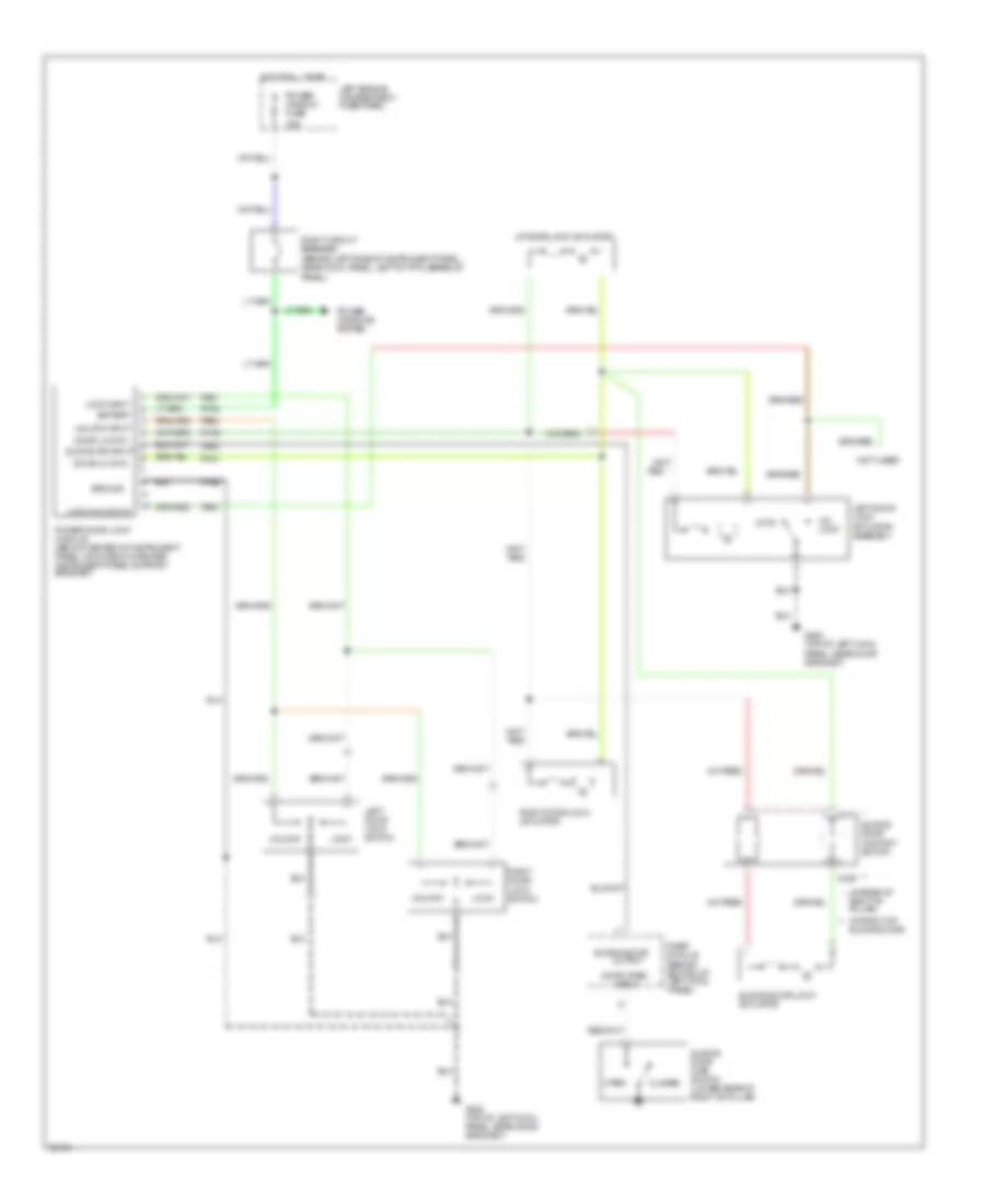
COOLING FAN
Cooling Fan Wiring Diagram for Mercury Villager GS 1993

List of elements for Cooling Fan Wiring Diagram for Mercury Villager GS 1993:
- (left front strut tower)
- (top right rear of eng.)
- Av92
- Cooling fan hi1 relay (eng. compt. relay block)
- Cooling fan hi2 relay (eng. compt. relay block)
- Cooling fan lo relay (eng. compt. relay block)
- Cooling fan motor
- Engine coolant temperature sensor
- Fa06
- Fa12
- Fuse block: i/p
- Fuse block: underhood (center)
- G102
- Hot at all times
- Hot in run or start
- Powertrain control module (behind glove box)
- Rad fan fuse 65a
- Rly coil fuse 10a
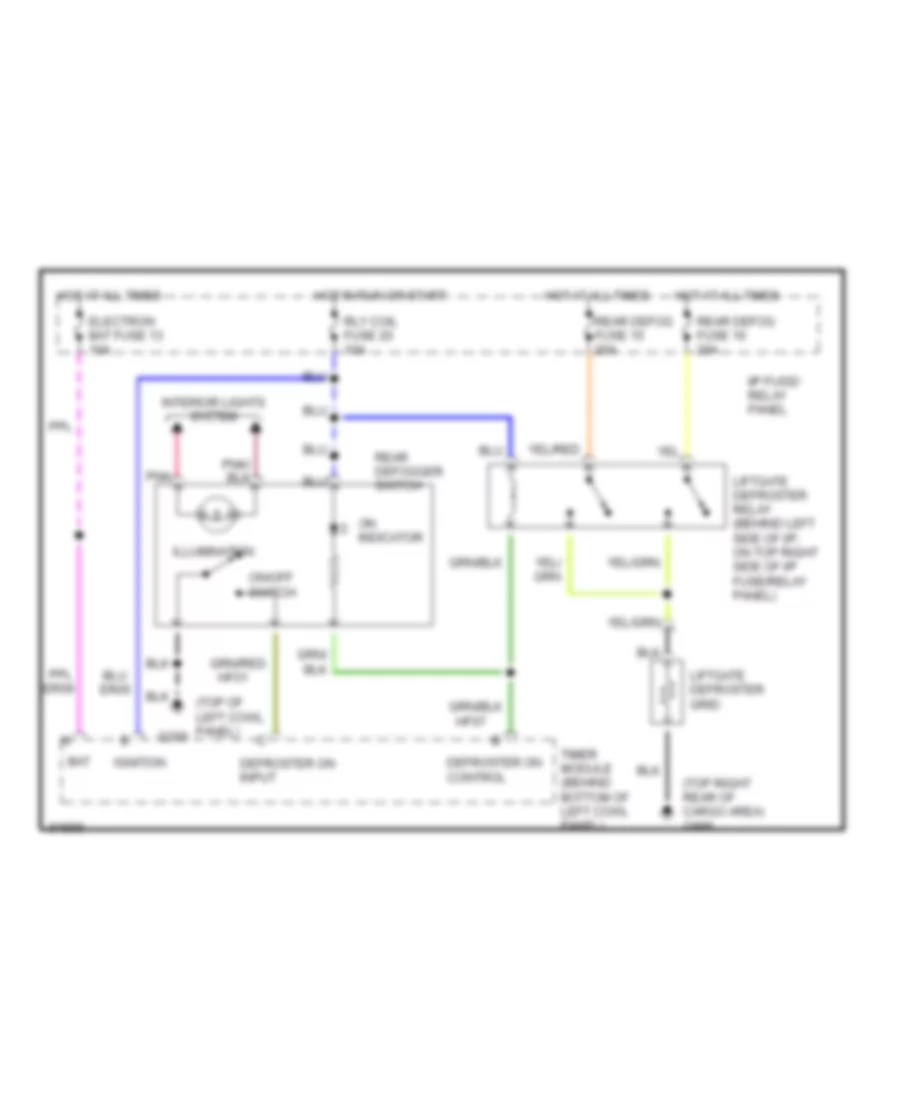
DEFOGGERS
Defogger Wiring Diagram for Mercury Villager GS 1993
List of elements for Defogger Wiring Diagram for Mercury Villager GS 1993:
- (top of left cowl panel)
- (top right rear of cargo area) g998
- Bat
- Defroster on control
- Defroster on input
- Electron bat fuse 13 10a
- Er05
- Er09
- G200
- Hf01
- Hf07
- Hot at all times
- Hot in run or start
- I/p fuse/ relay panel
- Ignition
- Illumination
- Interior lights system
- Liftgate defroster grid
- Liftgate defroster relay (behind left side of i/p, on top right side of i/p fuse/relay panel)
- On indicator
- On/off switch
- Pnk
- Rear defog fuse 15 20a
- Rear defog fuse 16 20a
- Rear defogger switch
- Rly coil fuse 20 10a
- Timer module (behind bottom of left cowl panel)
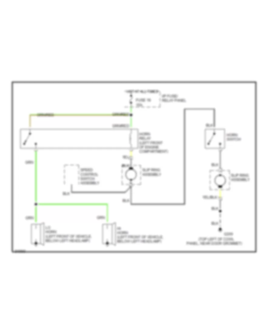
HORN
Horn Wiring Diagram for Mercury Villager GS 1993
List of elements for Horn Wiring Diagram for Mercury Villager GS 1993:
- (top left of cowl
- 15a
- Fuse 18
- G200
- Hi horn (left front of vehicle, below left headlamp)
- Horn relay (left front of engine compartment)
- Horn switch
- Hot at all times
- I/p fuse/ relay panel
- Lo horn (left front of vehicle, below left headlamp)
- Panel, near door grommet)
- Slip ring assembly
- Speed control switch assembly
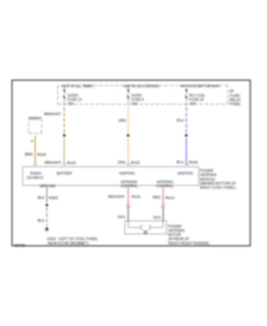
POWER ANTENNA
Power Antenna Wiring Diagram for Mercury Villager GS 1993
List of elements for Power Antenna Wiring Diagram for Mercury Villager GS 1993:
- (left of cowl panel,
- Antenna control
- Audio fuse 23 10a
- Audio fuse 9 10a
- Battery
- G200 near door grommet)
- Ground
- Hot at all times
- Hot in acc or run
- Hot in start or run
- I/p fuse/ relay panel
- Ignition
- Nca
- Power antenna module (behind bottom of right cowl panel)
- Power antenna motor (in rear of right front fender)
- Ra05
- Ra30
- Ra32
- Ra33
- Ra34
- Ra35
- Radio
- Radio on input
- Rae5
- Red
- Rly coil fuse 20 10a
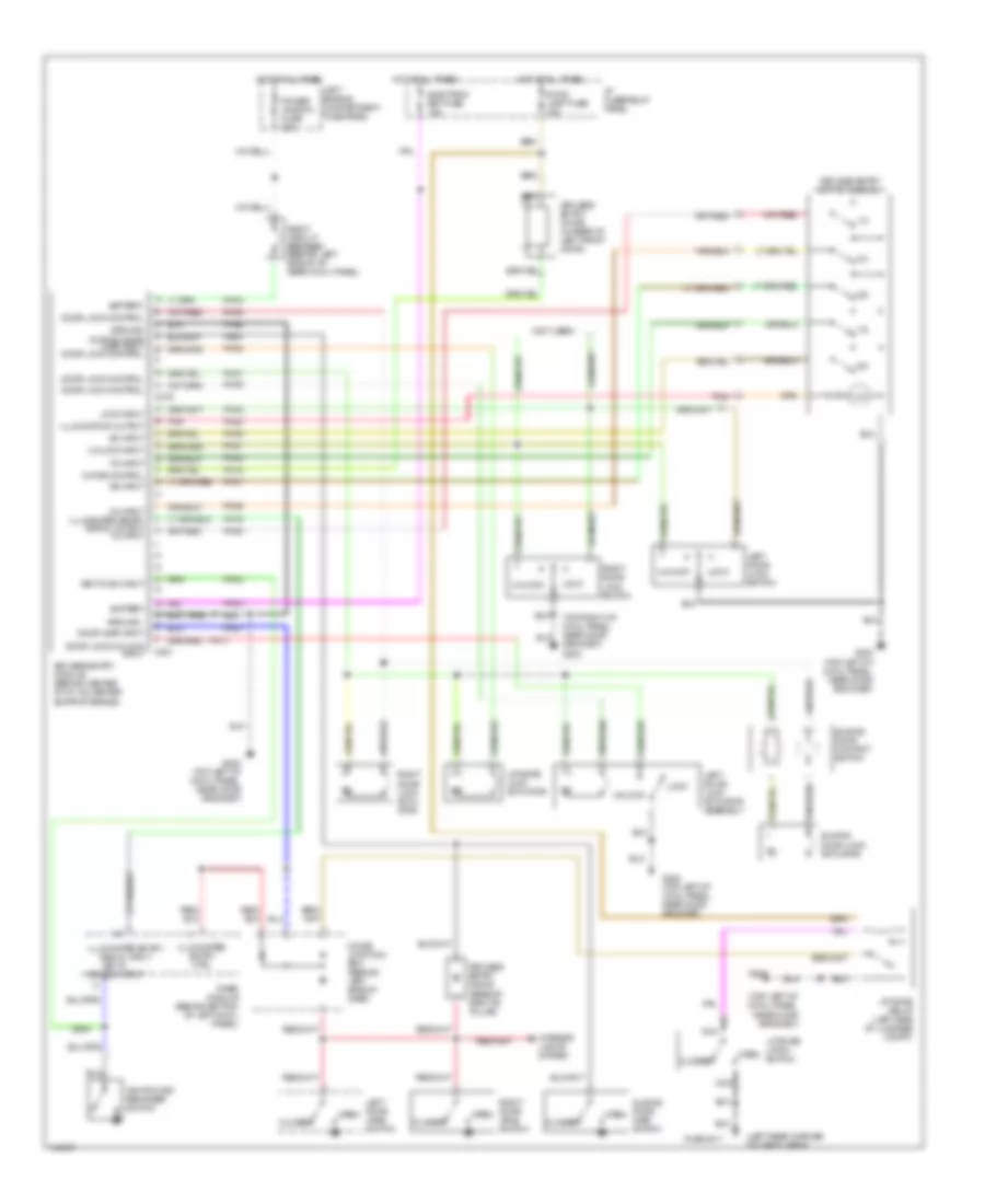
POWER DOOR LOCKS
Door Lock Wiring Diagram for Mercury Villager GS 1993
List of elements for Door Lock Wiring Diagram for Mercury Villager GS 1993:
- (behind left side of instrument panel, near cowl panel, left of i/p fuse/relay
- (in front of sliding door)
- (in rear of * right "b" pillar)
- (not used)
- 30a
- Battery
- C311
- C329
- Closed
- Door lk cntl
- Door open
- G200 (top of left cowl panel, near door grommet)
- Ground
- Hot at all times
- Input
- Left door lock switch
- Left door lock actuator assembly
- Left engine compartment fuse panel
- Liftgate lock actuator
- Lock
- Lock input
- Lock/unlock in
- Open
- Output
- Panel)
- Pb01
- Pb02
- Pb04
- Pb05
- Ph31
- Ph34
- Ph35
- Phe2
- Power window fuse
- Power door lock module (below center of instrument panel, mounted on center instrument panel support bracket)
- Power windows system
- Red
- Right door lock switch
- Right circuit breaker
- Right door lock actuator
- Sliding door
- Sliding door ajar switch (lower rear of right "b" pillar)
- Sliding door contact switch
- Sliding door lock actuator
- Sliding dr input
- Timer module (behind bottom of left cowl panel)
- Un- lock
- Unlock
- Unlock input
Keyless Entry Wiring Diagram for Mercury Villager GS 1993
List of elements for Keyless Entry Wiring Diagram for Mercury Villager GS 1993:
- (left rear corner of cargo area)
- (not used)
- (top left of cowl panel, near door grommet)
- (top right of cowl panel, near door grommet) g203
- 1/2
- 3/4
- 3/4 input illuminated entry signal output 1/2 input
- 5/6
- 5/6 input
- 7/8
- 7/8 input
- 9/0
- 9/0 input
- Battery
- C219
- C221
- Chime control
- Closed
- Diode junction box (behind left side of dash)
- Door ajar input
- Door lock control
- Door lock/unlock input
- Electron bat fuse 10a
- G200
- G200 (top left of cowl panel, near door grommet)
- G409,g411
- Ground
- Hot at all times
- I/p fuse/relay panel
- Ignition key reminder switch
- Illuminated entry ctrl
- Illuminated entry signal input
- Illumination output
- Interior lights system
- Key in ignition input
- Key-in ign input
- Keyless entry chime (in rear of left front door)
- Keyless entry diode (base of right b- pillar)
- Keyless entry keypad assembly
- Keyless entry module (behind center of i/p, on center support brace)
- Left door jamb switch
- Left door lock actuator assembly
- Left door lock switch
- Left engine compartment fuse panel
- Liftgate latch switch
- Liftgate lock actuator
- Liftgate relay (left side of luggage compt)
- Lock
- Lock input
- Nca
- Open
- Pb05
- Ph01
- Ph02
- Ph03
- Ph05
- Ph06
- Ph07
- Ph08
- Ph09
- Ph11
- Ph16
- Ph18
- Ph20
- Ph31
- Ph32
- Ph34
- Ph35
- Ph38
- Ph41
- Ph42
- Phe1
- Phe2
- Pnk
- Power window fuse 30a
- Right circuit breaker (behind left side of i/p, near cowl panel)
- Right door jamb switch
- Right door lock actu- ator
- Right door lock switch
- Room lamp fuse 15a
- Sliding door ajar input door lock control
- Sliding door ajar switch
- Sliding door contact switch
- Sliding door lock actuator
- Timer module (behind bottom of left cowl panel)
- Unlock
- Unlock input
Power Door Locks Wiring Diagram, without Keyless Entry for Mercury Villager GS 1993
List of elements for Power Door Locks Wiring Diagram, without Keyless Entry for Mercury Villager GS 1993:
- (behind left side of instrument panel, near cowl panel, left of i/p fuse/relay
- (in front of sliding door)
- (in rear of * right "b" pillar)
- (not used)
- 30a
- Battery
- C311
- C329
- Closed
- Door lk cntl
- Door open
- G200 (top of left cowl panel, near door grommet)
- Ground
- Hot at all times
- Input
- Left door lock switch
- Left door lock actuator assembly
- Left engine compartment fuse panel
- Liftgate lock actuator
- Lock
- Lock input
- Lock/unlock in
- Open
- Output
- Panel)
- Pb01
- Pb02
- Pb04
- Pb05
- Ph31
- Ph34
- Ph35
- Phe2
- Power window fuse
- Power door lock module (below center of instrument panel, mounted on center instrument panel support bracket)
- Power windows system
- Red
- Right door lock switch
- Right circuit breaker
- Right door lock actuator
- Sliding door
- Sliding door ajar switch (lower rear of right "b" pillar)
- Sliding door contact switch
- Sliding door lock actuator
- Sliding dr input
- Timer module (behind bottom of left cowl panel)
- Un- lock
- Unlock
- Unlock input
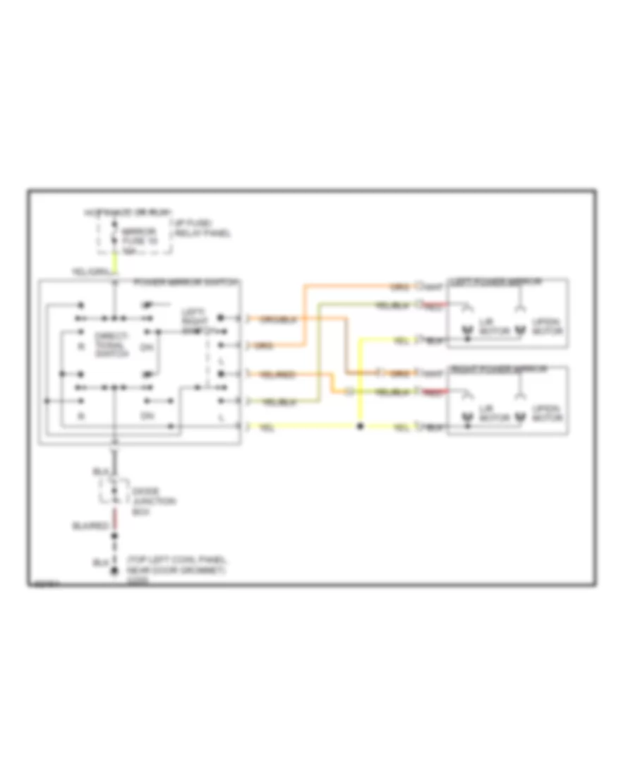
POWER MIRRORS
Power Mirror Wiring Diagram for Mercury Villager GS 1993
List of elements for Power Mirror Wiring Diagram for Mercury Villager GS 1993:
- (top left cowl panel, near door grommet) g200
- Diode junction box
- Direct- tional switch
- Hot in acc or run
- I/p fuse/ relay panel
- L/r motor
- Left/ right switch
- Mirror fuse 10 10a
- Power mirror switch
- Red
- Up/dn motor
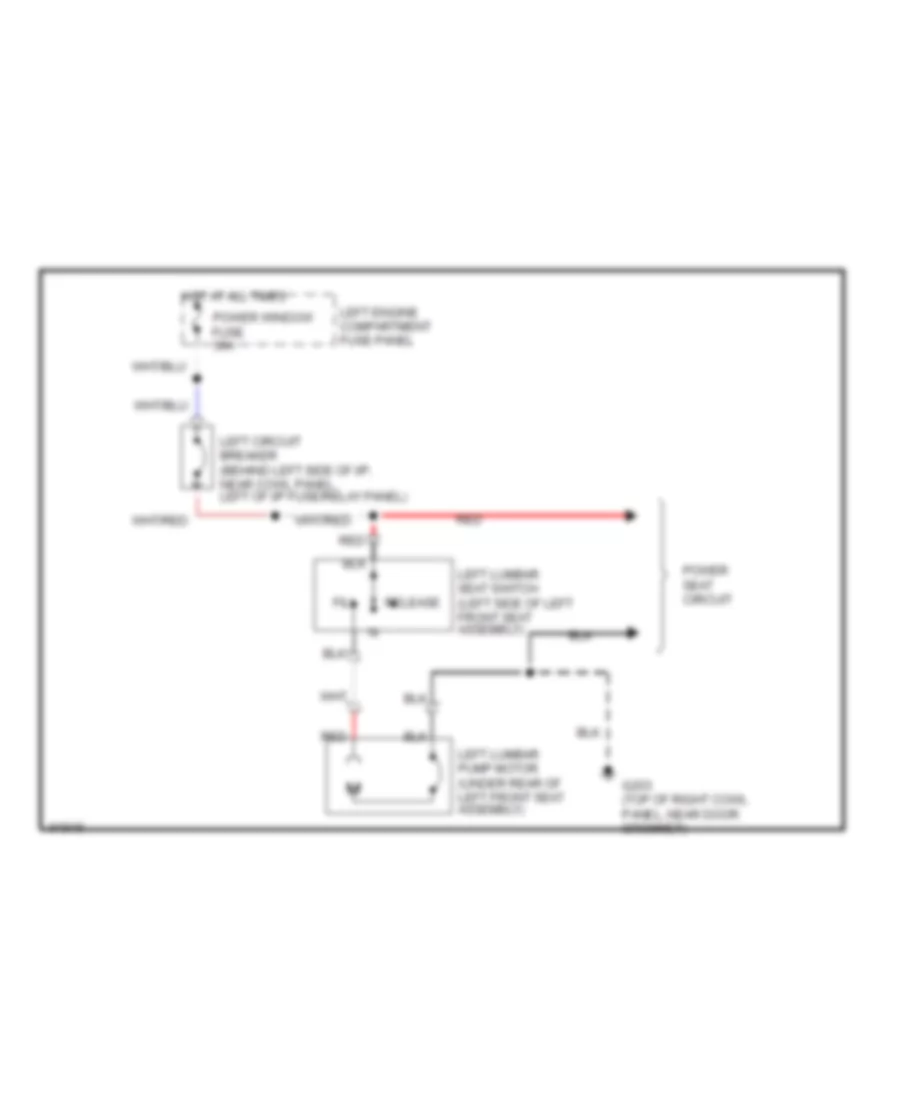
POWER SEATS
Lumbar Wiring Diagram for Mercury Villager GS 1993
List of elements for Lumbar Wiring Diagram for Mercury Villager GS 1993:
- Fill
- G203 (top of right cowl panel, near door grommet)
- Hot at all times
- Left circuit breaker (behind left side of i/p, near cowl panel, left of i/p fuse/relay panel)
- Left engine compartment fuse panel
- Left lumbar pump motor (under rear of left front seat assembly)
- Left lumbar seat switch (left side of left front seat assembly)
- Power seat circuit
- Power window fuse 30a
- Red
- Release
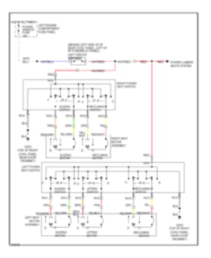
Power Seat Wiring Diagram for Mercury Villager GS 1993
List of elements for Power Seat Wiring Diagram for Mercury Villager GS 1993:
- (behind left side of i/p, near cowl panel, left of i/p fuse/relay panel)
- Cowl panel, near door grommet)
- G203 (top of right
- Hot at all times
- Left circuit breaker
- Left engine compartment fuse panel
- Left power seat switch
- Left seat motor assembly
- Lifting motor
- Lifting switch
- Nca
- Pnk
- Power lumbar seats system
- Power window fuse 30a
- Reclining motor
- Reclining switch
- Red
- Right power seat switch
- Right seat motor assembly
- Sliding motor
- Sliding switch
POWER WINDOWS
Power Window Wiring Diagram for Mercury Villager GS 1993
List of elements for Power Window Wiring Diagram for Mercury Villager GS 1993:
- (top of left cowl panel, near door grommet) g200
- (top of right cowl panel near door grommet) g203
- (top right cowl panel, near door grommet) g203
- Auto dn input
- Auto down
- Close
- Diode junction box (behind top left side of i/p, taped to main harness)
- Down
- Down input
- Fuse 20 rly coil 10a
- Ground
- Hot at all times
- Hot in start or run
- I/p fuse/ relay panel
- Ignition
- Left front power window motor
- Left rear power window motor
- Left window switch
- Lock
- Master window control switch
- Nca
- Neu- tral
- Off input
- Open
- Passenger power window control
- Passenger power window motor
- Pd03
- Pd07
- Pd08
- Pd09
- Pd14
- Pd15
- Pd16
- Pde2
- Power tops system
- Power window module (in rear of left front door)
- Power window relay (behind left side of i/p)
- Rear power window control
- Red
- Right circuit breaker
- Right rear power window motor
- Right window switch
- Un- lock
- Win mot cntl
- Window lock switch
RADIO
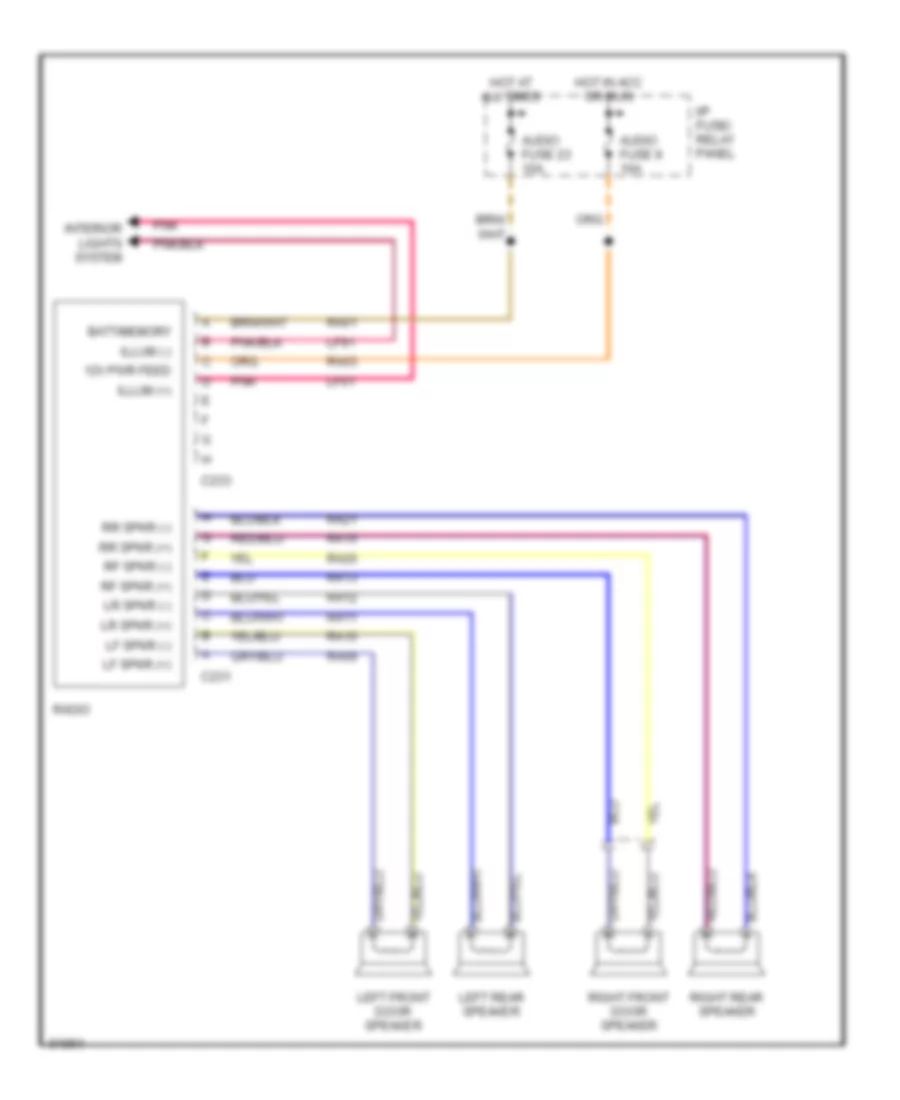
Radio Wiring Diagrams, Base Radio for Mercury Villager GS 1993
List of elements for Radio Wiring Diagrams, Base Radio for Mercury Villager GS 1993:
- 12v pwr feed
- Audio fuse 23 10a
- Audio fuse 9 10a
- Batt/memory
- C231
- C233
- Hot at all times
- Hot in acc or run
- I/p fuse/ relay panel
- Illum (+)
- Illum (-)
- Interior lights system
- Left front door speaker
- Left rear speaker
- Lf spkr (+)
- Lf spkr (-)
- Lf01
- Lf91
- Lr spkr (+)
- Lr spkr (-)
- Pnk
- Ra01
- Ra03
- Ra09
- Ra10
- Ra11
- Ra12
- Ra13
- Ra15
- Ra20
- Ra21
- Radio
- Rf spkr (+)
- Rf spkr (-)
- Right front door speaker
- Right rear speaker
- Rr spkr (+)
- Rr spkr (-)
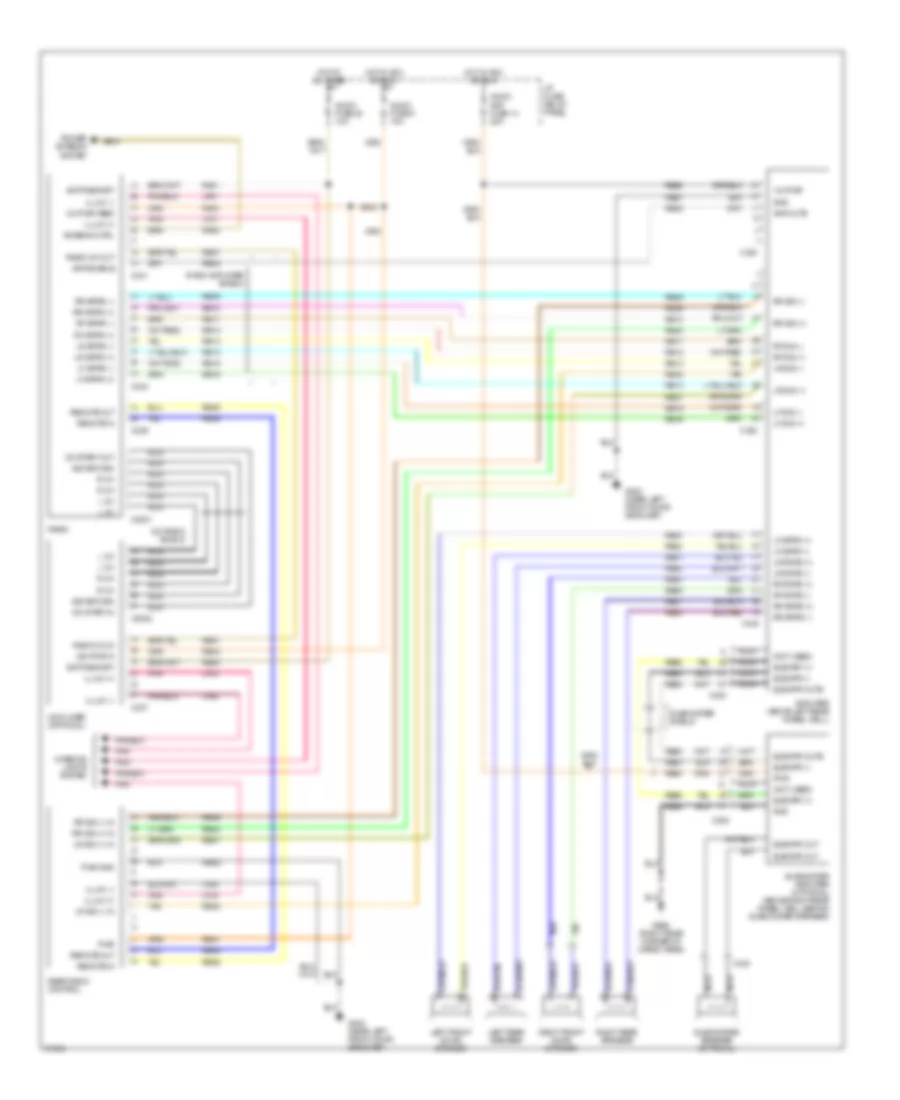
Radio Wiring Diagrams, High Level for Mercury Villager GS 1993
List of elements for Radio Wiring Diagrams, High Level for Mercury Villager GS 1993:
- (not used)
- 12v pwr
- 12v pwr feed
- Amp enable
- Amp mute
- Amplifier (above left rear wheel well)
- Antenna ctrl
- Audio amp fuse 14 20a
- Audio fuse 23 10a
- Audio fuse 9 10a
- Batt/memory
- C2001
- C2002
- C237
- C239
- C241
- C243
- C338
- C340
- C353
- C354
- C430
- Cd player (optional)
- Cd start in
- Cd start out
- Cd-radio shield
- G202 (near left front door grommet)
- G998 (right rear corner of cargo area)
- Gnd
- Hot at all times
- Hot in acc or run
- I/p fuse/ relay panel
- Ign pwr in
- Illum (+)
- Illum (-)
- Interior lights system
- L ch
- Left front door speaker
- Left rear speaker
- Lf sig (+)
- Lf sig (-)
- Lf spkr (+)
- Lf spkr (-)
- Lf01
- Lf02
- Lf04
- Lf91
- Lf92
- Lf94
- Lr sig (+)
- Lr sig (+) in
- Lr sig (-)
- Lr sig (-) in
- Lr spkr (+)
- Lr spkr (-)
- Nca
- Pnk
- Power antenna system
- Pwr
- Pwr gnd
- R ch
- Ra01
- Ra03
- Ra05
- Radio
- Radio amplifier shield
- Radio on in
- Radio on out
- Rb08
- Rb09
- Rb10
- Rb11
- Rb12
- Rb13
- Rb14
- Rb15
- Rb16
- Rb26
- Rb27
- Rb28
- Rb29
- Rb30
- Rb31
- Rb32
- Rb33
- Rb34
- Rb35
- Rb36
- Rb37
- Rb38
- Rb40
- Rb41
- Rb42
- Rb49
- Rb50
- Rb51
- Rb52
- Rb53
- Rb54
- Rb55
- Rbe1
- Rbe2
- Rbe3
- Rear radio control
- Remote in
- Remote out
- Rf sig (+)
- Rf sig (-)
- Rf spkr (+)
- Rf spkr (-)
- Right front door speaker
- Right rear speaker
- Rr sig (+)
- Rr sig (+) in
- Rr sig (-)
- Rr sig (-) in
- Rr spkr (+)
- Rr spkr (-)
- Sig return
- Subwfr (-)
- Subwfr mute
- Subwfr out
- Subwoofer amplifier (optional) (above right rear wheel well behind subwoofer speaker)
- Subwoofer shield
- Subwoofer speaker (optional)
- Subwrf (+)
- Tan
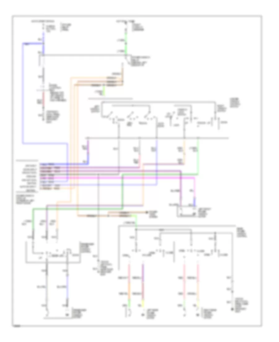
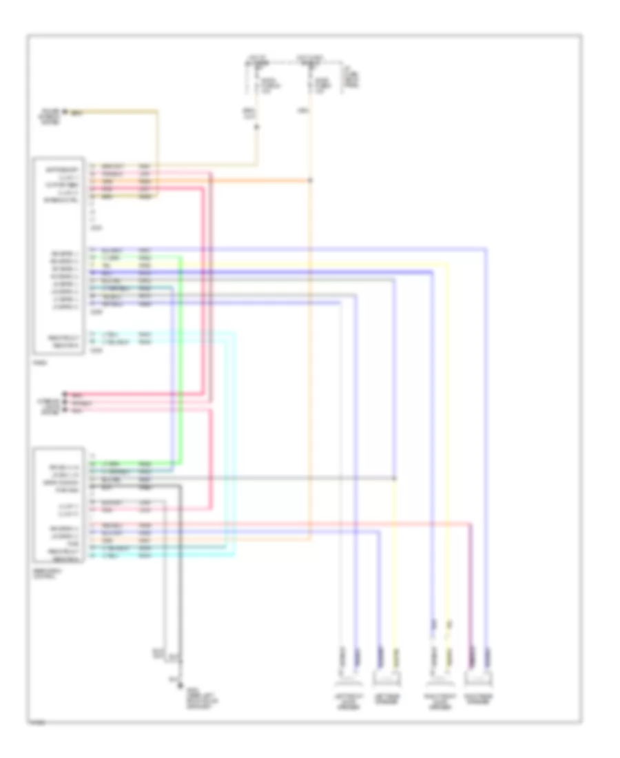
Radio Wiring Diagrams, Mid Level for Mercury Villager GS 1993
List of elements for Radio Wiring Diagrams, Mid Level for Mercury Villager GS 1993:
- 12v pwr feed
- Antenna ctrl
- Audio fuse 23 10a
- Audio fuse 9 10a
- Batt/memory
- C229
- C233
- C235
- G202 (near left front door grommet)
- Hot at all times
- Hot in acc or run
- I/p fuse/ relay panel
- Illum (+)
- Illum (-)
- Interior lights system
- Left front door speaker
- Left rear speaker
- Lf spkr (+)
- Lf spkr (-)
- Lf01
- Lf04
- Lf91
- Lf94
- Lr sig (-) in
- Lr spkr (+)
- Lr spkr (-)
- Pnk
- Power antenna system
- Pwr
- Pwr gnd
- Ra01
- Ra03
- Ra05
- Ra09
- Ra10
- Ra12
- Ra13
- Ra14
- Ra16
- Ra20
- Ra21
- Ra22
- Ra23
- Ra27
- Ra28
- Ra29
- Ra31
- Radio
- Rae2
- Rear radio control
- Remote in
- Remote out
- Rf spkr (+)
- Rf spkr (-)
- Right front door speaker
- Right rear speaker
- Rr sig (+) in
- Rr spkr (+)
- Rr spkr (-)
- Spkr common
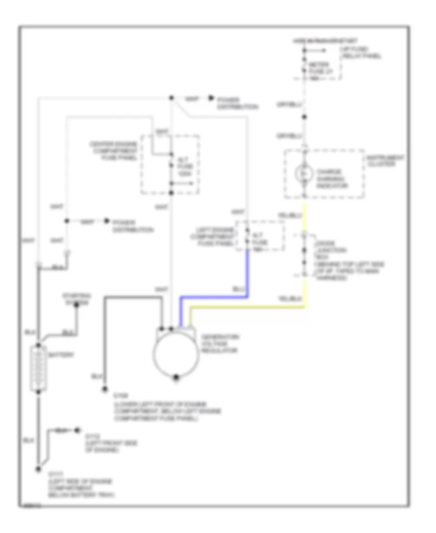
STARTING/CHARGING
Charging Wiring Diagram for Mercury Villager GS 1993
List of elements for Charging Wiring Diagram for Mercury Villager GS 1993:
- (lower left front of engine compartment, below left engine compartment fuse panel)
- Alt fuse 10a
- Alt fuse 120a
- Battery
- Center engine compartment fuse panel
- Charge warning indicator
- Diode junction box (behind top left side of i/p, taped to main harness)
- G108
- G111 (left side of engine compartment, below battery tray)
- G112 (left front side of engine)
- Generator/ voltage regulator
- Hot in run or start
- I/p fuse/ relay panel
- Instrument cluster
- Left engine compartment fuse panel
- Meter fuse 21 10a
- Power distribution
- Starting system
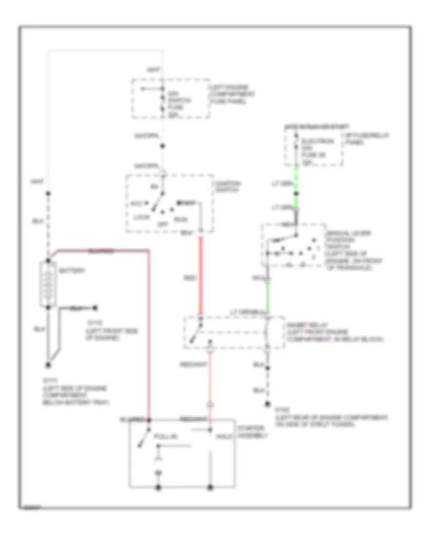
Starting Wiring Diagram for Mercury Villager GS 1993
List of elements for Starting Wiring Diagram for Mercury Villager GS 1993:
- (left front side of engine)
- (left rear of engine compartment, on side of strut tower)
- (left side of engine compartment, below battery tray)
- (left side of engine, on front of transaxle)
- Acc
- Battery
- Electron ign fuse 26 10a
- G102
- G111
- G112
- Hold
- Hot in run or start
- I/p fuse/relay panel
- Ign switch fuse 30a
- Ignition switch
- Inhibit relay (left front engine compartment, in relay block)
- Left engine compartment fuse panel
- Lock
- Manual lever position switch
- Nca
- Off
- Pull-in
- Red
- Run
- Sta
- Start
- Starter assembly
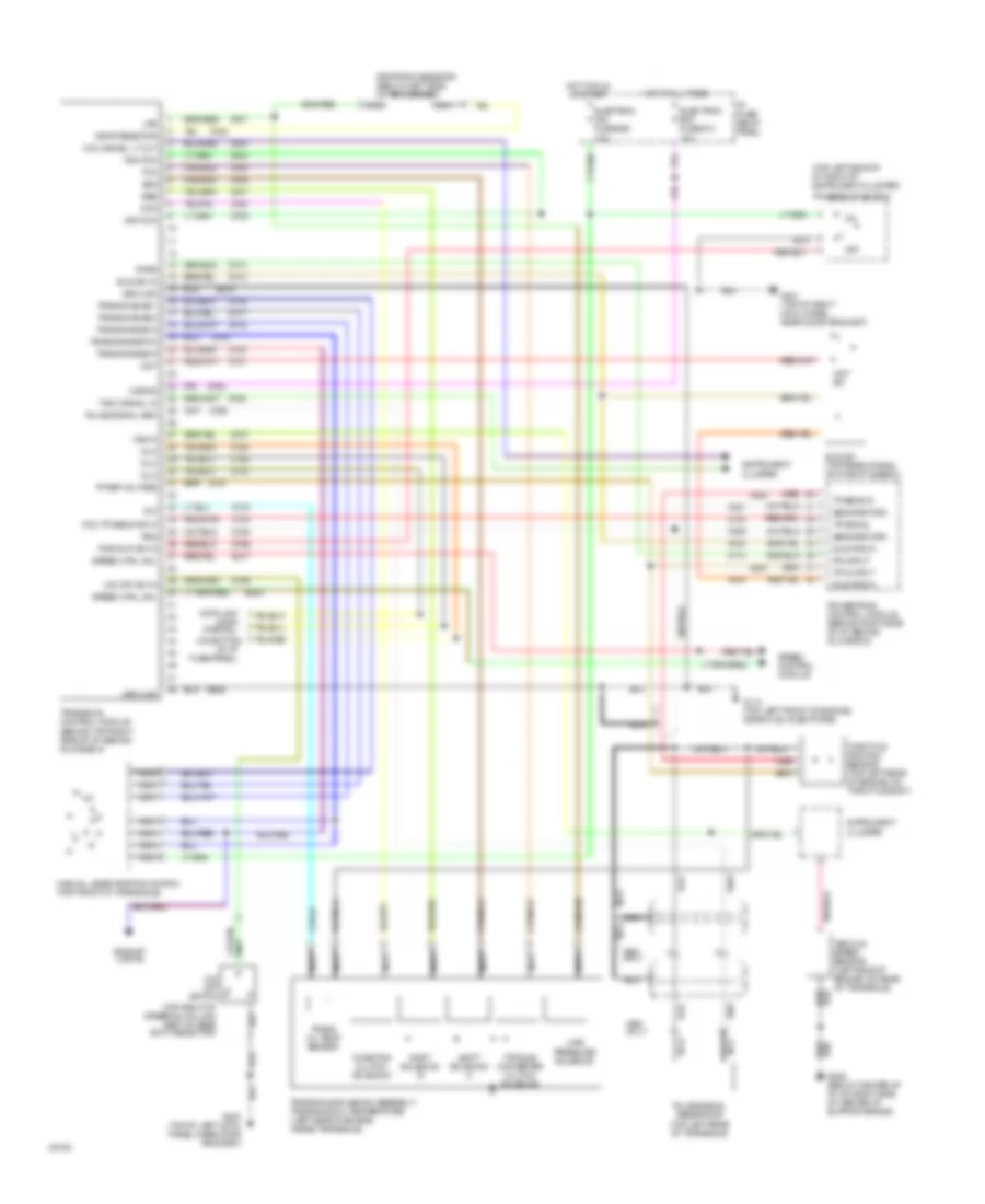
TRANSMISSION
Transmission Wiring Diagram for Mercury Villager GS 1993
List of elements for Transmission Wiring Diagram for Mercury Villager GS 1993:
- (behind top right side of i/p, behind glove box)
- (on bottom
- (top left side of i/p, right of instrument cluster)
- (top right of steering column part of gear shift selector)
- Av20
- Av21
- Av29
- Av33
- Av37
- Av44
- Backup lights
- Ccs
- Coasting clutch solenoid
- Data link conn (partial)
- Dlc
- Drop resistor
- Dropping resistor (below left side of air cleaner)
- Ej08
- Ej17
- Electron bat fuse #13 10a
- Electron ign fuse #26 10a
- G114 (top left front of engine, near fuel injector #6)
- G200 (top of left cowl panel, near door grommet)
- G201 (top of right cowl panel, near door grommet)
- G206 (below center of i/p, on right side of center i/p support brace)
- Ground
- Hot at all times
- Hot in run or start
- I/p fuse/ relay panel
- Idle pos in
- Idle sw (top rear of eng, on throttle body)
- Idle sw in
- Ignition
- Instrument cluster
- Kapwr
- Line pressure solenoid
- Lps
- Manual lever position switch (top front of transaxle)
- Nca
- O/d cancel lt out
- O/d off sw in
- O/d off switch
- Of i/p fuse/panel)
- Off
- Only
- P/n input
- Pcm tp sens input
- Pnps
- Power e-at switch
- Powertrain control module (behind right side of i/p, behind glove box)
- Psg
- Pulse signal gen
- Pulse signal generator (top left rear of transaxle)
- Pwr e-at sw in
- Red
- Sens return
- Shift solenoid a
- Shift solenoid b
- Speed control module
- Speed ctrl mdl
- Ssa
- Ssb
- Tach signal in
- Tcc
- Throttle position sensor (top left rear of engine, on throttle body)
- Torque converter clutch solenoid
- Tot
- Tp output
- Tp ref voltage
- Tp sens in
- Tp signal
- Trans oil temp sensor
- Trans range 1
- Trans range 2
- Trans range d
- Trans range p/n
- Trans range r
- Transaxle control module
- Transaxle solenoid assembly/ transaxle oil temperature (left side of engine, inside transaxle)
- Vehicle speed sensor (left side of engine, on rear of transaxle)
- Vss in
- Wot
- Wot sw
- Ze15
- Ze48
- Zy01
- Zy02
- Zy03
- Zy04
- Zy05
- Zy06
- Zy07
- Zy08
- Zy09
- Zy13
- Zy14
- Zy16
- Zy17
- Zy18
- Zy19
- Zy20
- Zy21
- Zy23
- Zy24
- Zy25
- Zy27
- Zy28
- Zy29
- Zy30
- Zy31
- Zy33
- Zy34
- Zy35
- Zy36
- Zy39
WIPER/WASHER
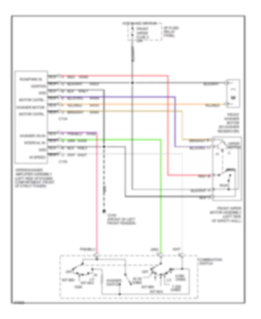
Front Washer/Wiper Wiring Diagram for Mercury Villager GS 1993
List of elements for Front Washer/Wiper Wiring Diagram for Mercury Villager GS 1993:
- 100k
- 36.3k ohms int min
- 4.08k
- 7.25k ohms
- B red
- C134
- C136
- Combination switch
- Front washer motor (in washer reservoir)
- Front wiper fuse 6 20a
- Front wiper motor assembly (left side of safety wall)
- G100 (front of left front fender)
- Gnd
- Hot in acc or run
- I/p fuse/ relay panel
- Ignition
- Int max
- Int min
- L wiper motor
- Motor cntrl
- Nca
- Nca hi speed
- Nca interval in
- Nca washer on in
- Off
- Ohms
- Park
- Red
- Run
- Run/park in
- Wa03
- Wa04
- Wa05
- Wa06
- Wa07
- Wa08
- Wa09
- Wa10
- Wae1
- Wae3
- Washer motor
- Washer switch
- Wiper/washer amplifier assembly (left side of engine compartment, front of strut tower)
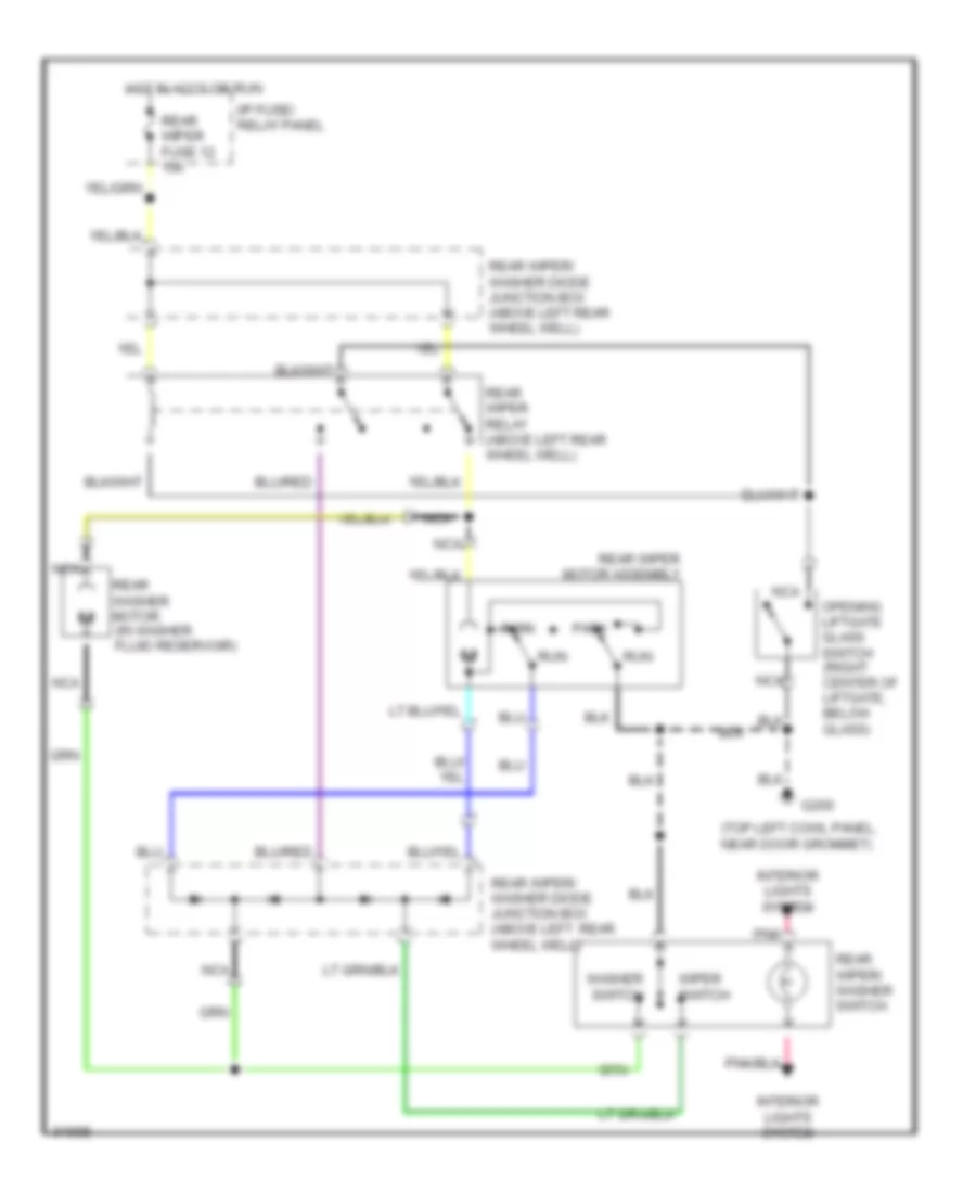
Rear Wiper/Washer Wiring Diagram, with Moveable Liftgate Glass for Mercury Villager GS 1993
List of elements for Rear Wiper/Washer Wiring Diagram, with Moveable Liftgate Glass for Mercury Villager GS 1993:
- (top left cowl panel, near door grommet)
- G200
- Hot in accy or run
- I/p fuse/ relay panel
- Interior lights system
- Nca
- Opening liftgate glass switch (right center of liftgate, below glass)
- Park
- Pnk
- Rear washer motor (in washer fluid reservoir)
- Rear wiper fuse 12 15a
- Rear wiper motor assembly
- Rear wiper relay (above left rear wheel well)
- Rear wiper/ washer diode junction box (above left rear wheel well)
- Rear wiper/ washer diode junction box (above left rear wheel well)
- Rear wiper/ washer switch
- Run
- Washer switch
- Wiper switch
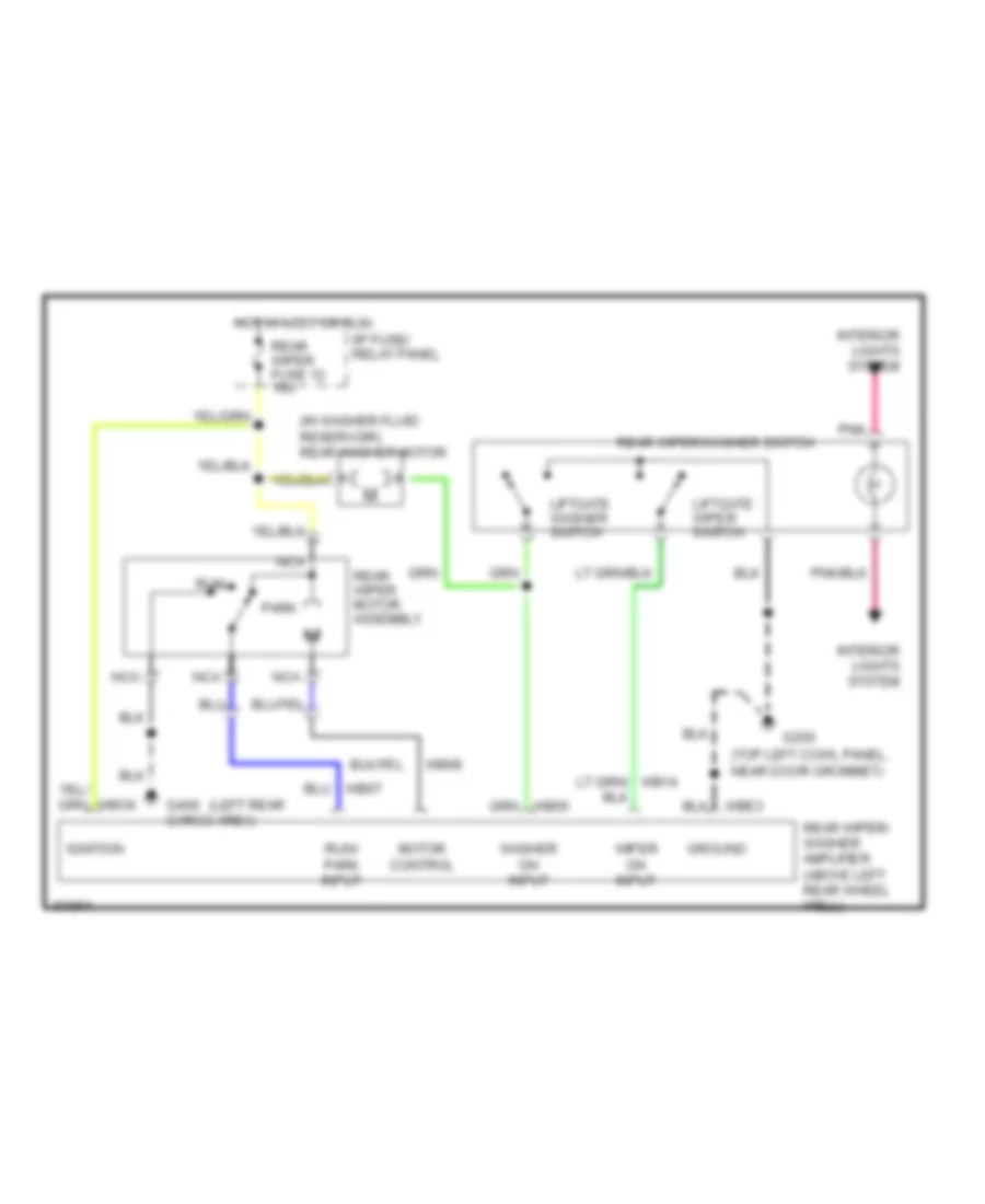
Rear Wiper/Washer Wiring Diagram, without Moveable Liftgate Glass for Mercury Villager GS 1993
List of elements for Rear Wiper/Washer Wiring Diagram, without Moveable Liftgate Glass for Mercury Villager GS 1993:
- (in washer fluid reservoir) rear washer motor
- (left rear
- (top left cowl panel, near door grommet)
- G200
- G409 cargo area)
- Ground
- Hot in accy or run
- I/p fuse/ relay panel
- Ignition
- Interior lights system
- Liftgate washer switch
- Liftgate wiper switch
- Motor control
- Nca
- Park
- Pnk
- Rear wiper fuse 12 15a
- Rear wiper motor assembly
- Rear wiper/ washer amplifier (above left rear wheel well)
- Rear wiper/washer switch
- Run
- Run/ park input
- Washer on input
- Wb08
- Wiper on input