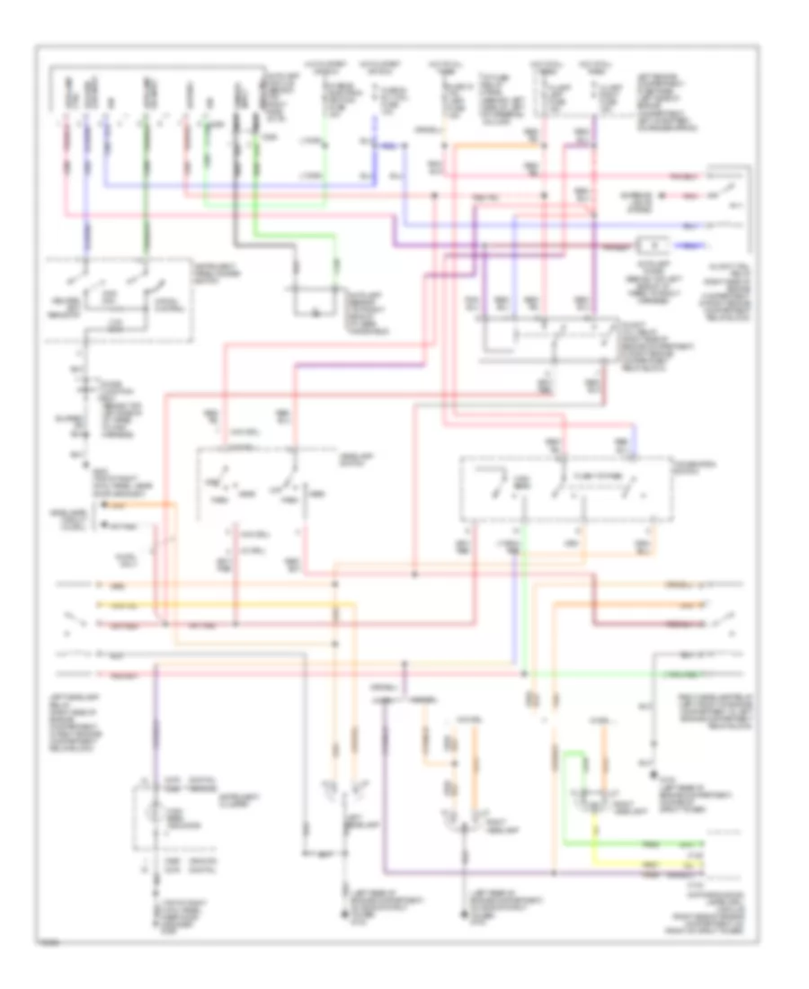
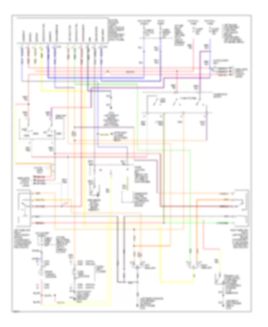
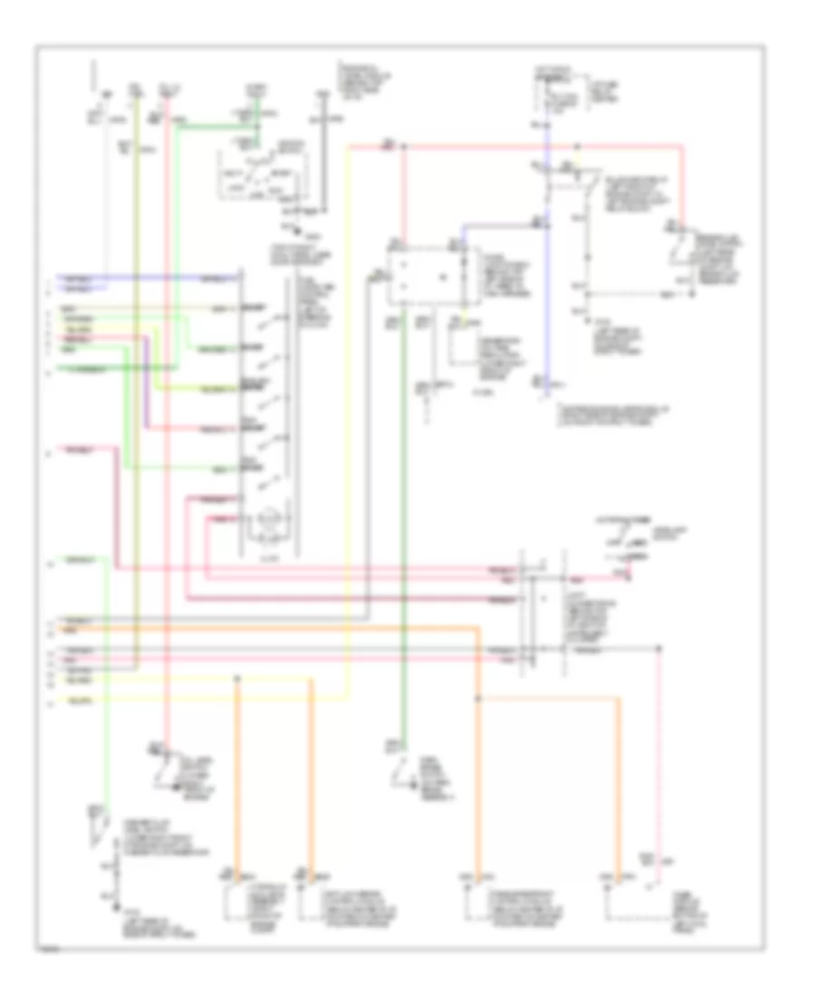
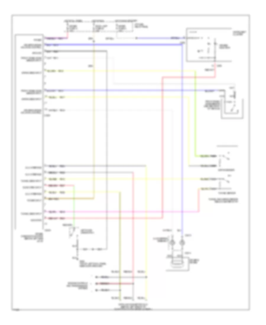
AIR CONDITIONING
A/C Wiring Diagram for Mercury Villager LS 1995

List of elements for A/C Wiring Diagram for Mercury Villager LS 1995:
- #1 front blower motor fuse 20a
- #13 electron bat fuse 10a
- #2 front blower motor fuse 20a
- #20 rly coil fuse 10a
- #21 meter fuse 10a
- (on left
- A/c compressor clutch coil
- A/c high pressure switch (right front of engine)
- A/c low pressure switch (right side of engine compartment, on accumulator)
- A/c press switches
- A/c relay (in left engine compartment relay box)
- Acc
- Auxiliary a/c-heater circuit
- Bi-lev/flr input
- C 1995 vftc
- Center engine compartment fuse panel
- Cooling fan hi1 relay (in left engine compartment relay block)
- Cooling fan hi2 relay (in left engine compartment relay block)
- Cooling fan lo relay (in left engine compartment relay block)
- Cooling fan motor
- Def input
- Fa06
- Fa12
- Flr,flr/def input
- Flr/def or def input
- Fresh/recirc dr act
- Fresh/recirculation door actuator (behind right side of i/p, on plenum)
- Front blend door actuator (behind right side of i/p, on plenum)
- Front blower motor
- Front blower motor relay (behind right side of i/p, on plenum)
- Front blower motor resistor assembly (behind right side of i/p, in plenum)
- Front blower motor switch
- Front climate control panel
- Frt blend dr act
- Frt blend dr mtr act
- Frt blower mtr ctrl
- G102
- G110 (top left front of engine)
- G200 (top of left cowl panel)
- Ground
- Ha01
- Ha02
- Ha04
- Ha05
- Ha06
- Ha09
- Ha11
- Ha12
- Ha13
- Ha14
- Ha15
- Ha16
- Ha17
- Ha18
- Ha20
- Ha21
- Ha22
- Ha23
- Ha24
- Ha28
- Ha41
- Ha45
- Hae4
- Hb21
- He01
- Hot at all times
- Hot in start or run
- Hx01
- I/p fuse/ relay panel
- Ignition
- Ignition switch
- Ih01
- Ih91
- Illumination
- Interior lights system
- Lock
- Mode act motor
- Mode act sig return
- Mode actuator
- Mode actuator (behind center of i/p)
- Nca
- Off
- Pnk
- Position switches
- Power
- Powertrain control module (behind glove box)
- Rad fan fuse 65a
- Rear blw mtr sw
- Run
- Start
- Strut
- Tower)
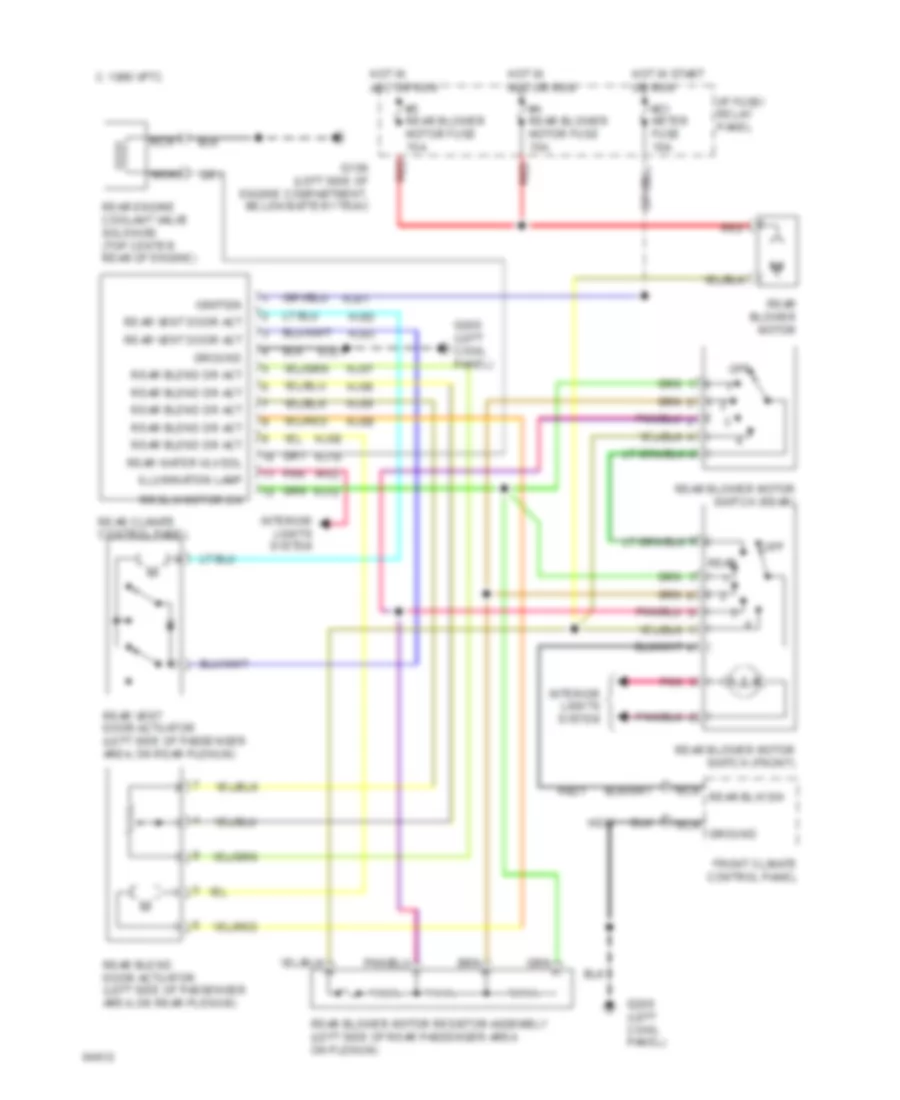
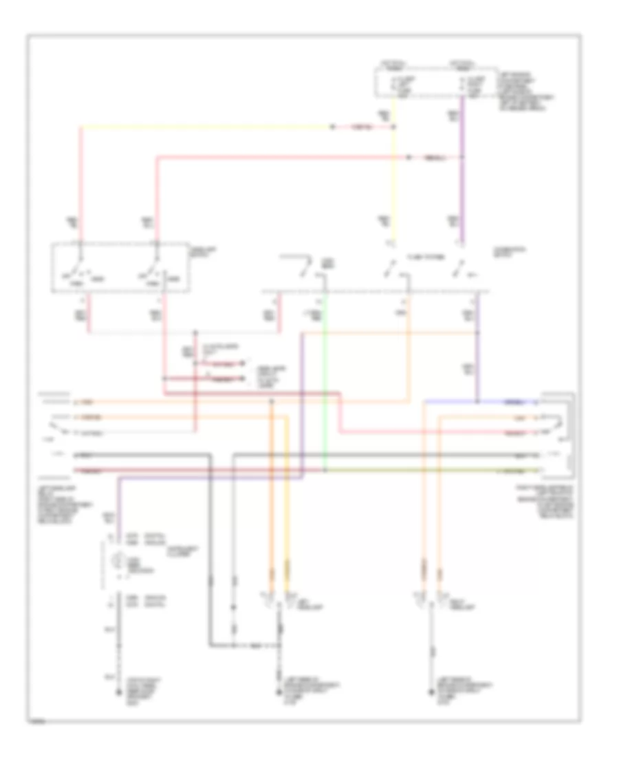
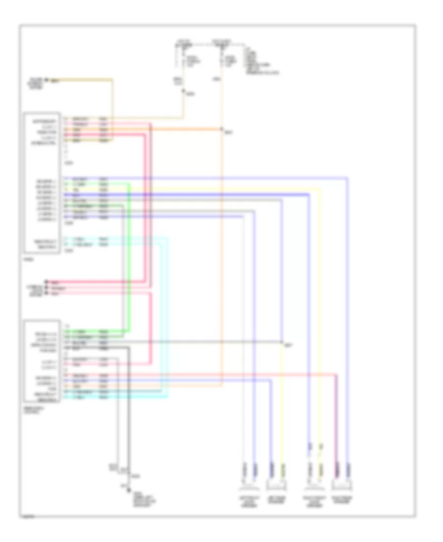
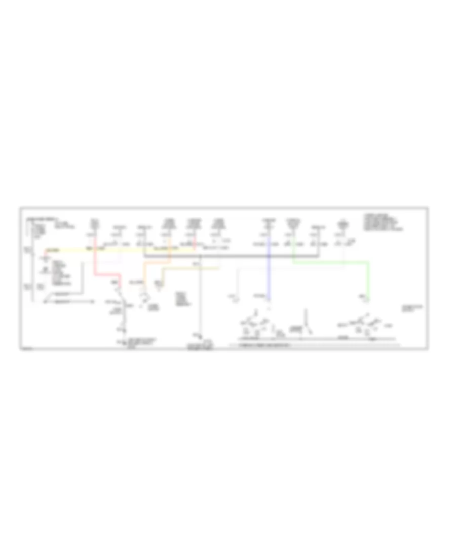
Rear A/C Wiring Diagram for Mercury Villager LS 1995
List of elements for Rear A/C Wiring Diagram for Mercury Villager LS 1995:
- #21 meter fuse 10a
- #4 rear blower motor fuse 15a
- #5 rear blower motor fuse 15a
- C 1995 vftc
- Front climate control panel
- G100 (left side of engine compartment, below battery tray)
- G200 (left cowl panel)
- G200 (left cowl panel)
- Ground
- Hb21
- He01
- Hj01
- Hj02
- Hj03
- Hj05
- Hj06
- Hj07
- Hj08
- Hj09
- Hj10
- Hj12
- Hje1
- Hot in acc or run
- Hot in start or run
- I/p fuse/ relay panel
- Ignition
- Ih02
- Illumination lamp
- Interior lights system
- Nca
- Nca ground
- Nca rear blw sw
- Off
- Pnk
- Rear
- Rear blend door actuator (left side of passenger area, on rear plenum)
- Rear blend dr act
- Rear blower motor
- Rear blower motor resistor assembly (left side of rear passenger area on plenum)
- Rear blower motor switch (front)
- Rear blower motor switch (rear)
- Rear climate control panel
- Rear engine coolant valve solenoid (top center rear of engine)
- Rear vent door act
- Rear vent door actuator (left side of passenger area, on rear plenum)
- Rear water vlv sol
- Red
- Rr blw motor sw
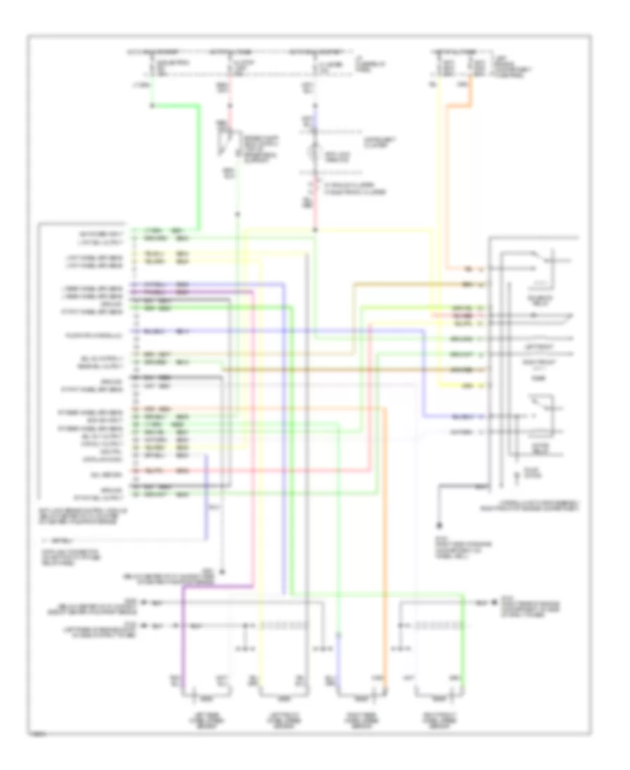
ANTI-LOCK BRAKES
Anti-lock Brake Wiring Diagrams for Mercury Villager LS 1995
List of elements for Anti-lock Brake Wiring Diagrams for Mercury Villager LS 1995:
- 21 meter 15a
- 24 stop lamp 15a
- 26 electron ign 10a
- Anti- skid 20a
- Anti- skid 30a
- Anti-lock brake control module (below center of i/p, mounted on center i/p support brace)
- Anti-lock warn ind
- Boo sw input
- Brake on/off (boo) switch (top of brake pedal support)
- Bs01
- Bs02
- Bs04
- Bs05
- Bs08
- Bs09
- Bs14
- Bs17
- Bs18
- Bs21
- Bs23
- Bs24
- Bs25
- Bs26
- Bs27
- Bs28
- Bs29
- Bs30
- Bs32
- Bs35
- Data link conn
- Data link connector (on bottom of i/p fuse/ relay panel)
- Eb10
- Eb20
- Eb34
- G102 (left rear of engine compt, on side of strut tower)
- G103 (right rear of engine compartment, on side of strut tower)
- G103 (right side of engine compartment, on wheel well)
- G201 (below center of i/p, on right side of center i/p support brace)
- G206 (below center of i/p, on right side of center i/p support brace)
- Ground
- Hot at all times
- Hot in run or start
- Hydraulic actuator assembly (right front of engine compartment)
- I/p fuse/relay panel
- Ign power input
- Ind ctrl
- Instrument cluster
- L fnt sol output
- L fnt wheel spd sens
- L rear wheel spd sens
- Left engine compartment fuse panel
- Left front
- Left front wheel speed sensor
- Left rear wheel speed sensor
- Motor relay
- Mtr rly output
- Pump motor
- Pump mtr (hydraulic)
- Rear
- Rear sol output
- Right front
- Right front wheel speed sensor
- Right rear wheel speed sensor
- Rt fnt sol output
- Rt fnt wheel spd sens
- Rt rear wheel spd sens
- Sol return
- Sol rly output
- Sol rly/mtr rly
- Solenoid relay
- W/ analog cluster
- W/ electronic cluster
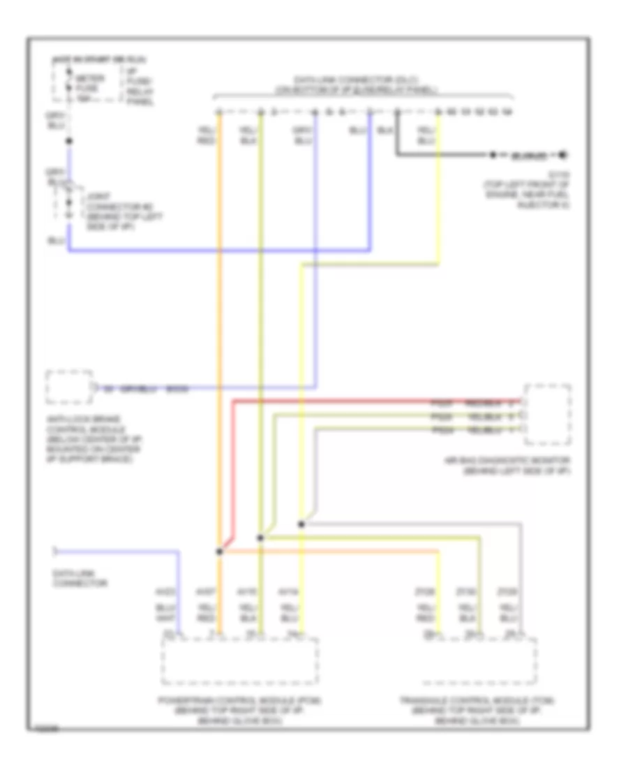
COMPUTER DATA LINES
Computer Data Lines for Mercury Villager LS 1995
List of elements for Computer Data Lines for Mercury Villager LS 1995:
- Air bag diagnostic monitor (behind left side of i/p)
- Anti-lock brake control module (below center of i/p, mounted on center i/p support brace)
- Av07
- Av14
- Av15
- Av23
- Bs30
- Data link connector
- Data link connector (dlc) (on bottom of i/p fuse/relay panel)
- G110 (top left front of engine, near fuel injector 6)
- Hot in start or run
- I/p fuse/ relay panel
- Joint connector #2 (behind top left side of i/p)
- Meter fuse 10a
- Powertrain control module (pcm) (behind top right side of i/p, behind glove box)
- Ps24
- Ps25
- Ps26
- Transaxle control module (tcm) (behind top right side of i/p, behind glove box)
- Zy28
- Zy29
- Zy30
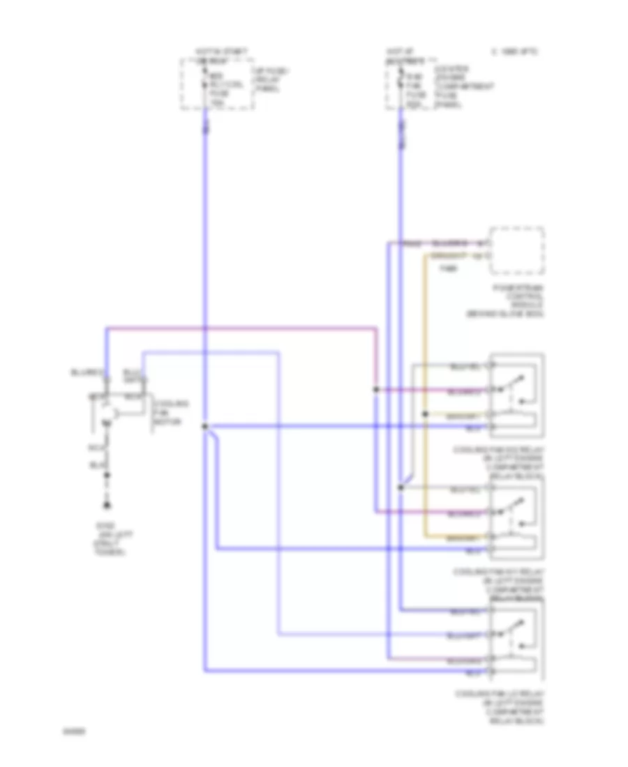
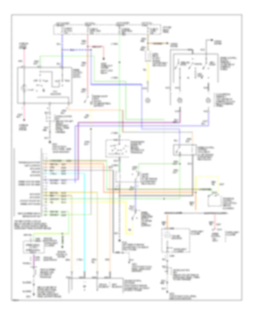
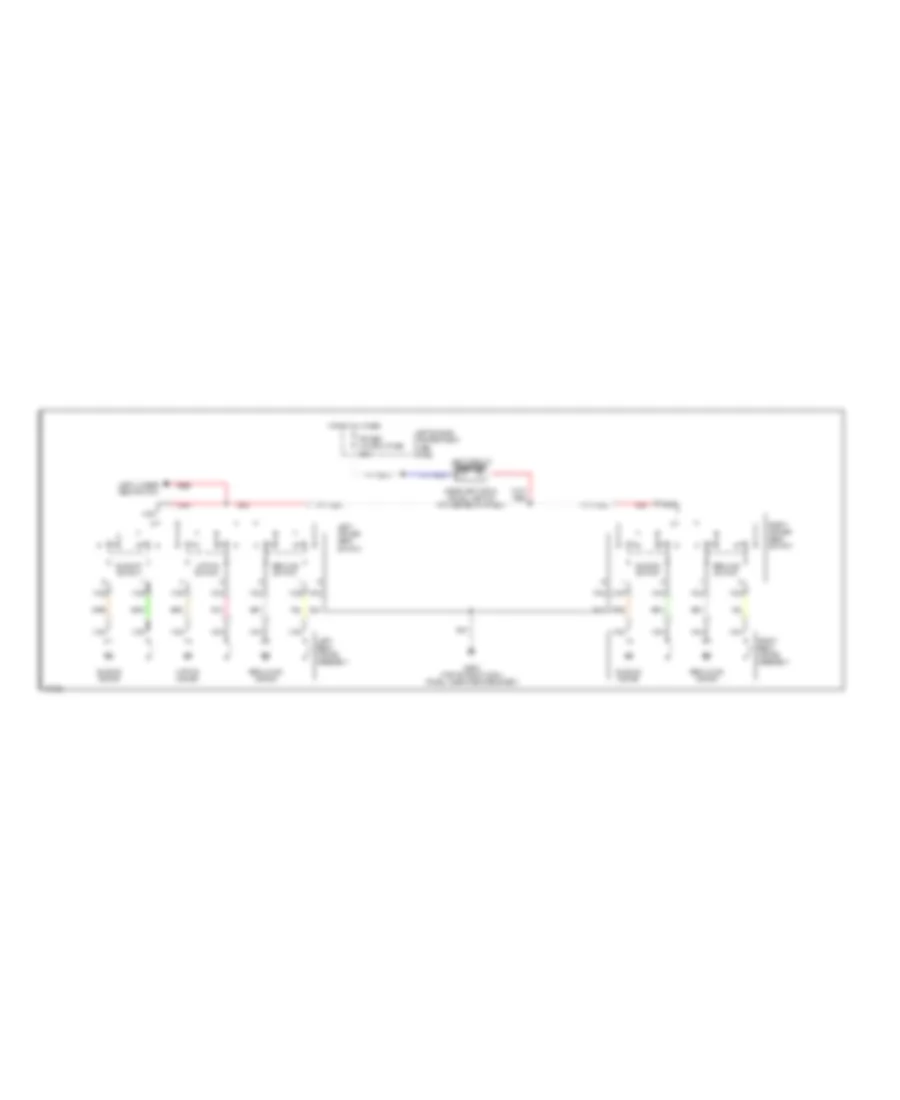
COOLING FAN
Cooling Fan Wiring Diagram for Mercury Villager LS 1995
List of elements for Cooling Fan Wiring Diagram for Mercury Villager LS 1995:
- #20 rly coil fuse 10a
- (on left
- C 1995 vftc
- Center engine compartment fuse panel
- Cooling fan hi1 relay (in left engine compartment relay block)
- Cooling fan hi2 relay (in left engine compartment relay block)
- Cooling fan lo relay (in left engine compartment relay block)
- Cooling fan motor
- Fa06
- Fa12
- G102
- Hot at all times
- Hot in start or run
- I/p fuse/ relay panel
- Nca
- Powertrain control module (behind glove box)
- Rad fan fuse 65a
- Strut
- Tower)
CRUISE CONTROL
Cruise Control Wiring Diagram for Mercury Villager LS 1995
List of elements for Cruise Control Wiring Diagram for Mercury Villager LS 1995:
- "cruise" indicator
- "on"
- "on" input
- (analog) (electronic)
- (behind top left side of instrument panel, taped to main harness)
- (below center of instrument panel, on right side of center instrument panel support brace)
- (in left engine compartment relay block)
- (right side of engine, compartment on front of strut tower)
- (shift lock relay)
- (top of right cowl panel, near
- Accel
- Actuator
- Analog cluster
- Brake on/off (boo) switch (on brake pedal support)
- Brake on/off sw
- C266
- C268 c272
- C274
- Cancel
- Clockspring assembly (top center of steering column, below steering wheel)
- Compartment relay block)
- Cr cont on/off sw
- Cruise control actuator
- Cruise control module (below center of instrument panel, on right side of center instrument panel support brace)
- Diode junction box
- Diode junction box (behind top left side of instrument panel, taped to main harness)
- Door grommet)
- Ej04
- Ej06
- Ej07
- Ej08
- Ej09
- Ej10
- Ej13
- Ej14
- Ej15
- Ej16
- Eje1
- Ejo1
- Ejo2
- Electronic cluster
- Engine compartment relay block)
- Engine controls system
- Fuse 18 horn 15a
- Fuse 20 rly coil 10a
- Fuse 24 stop lamp 15a
- Fuse 26 electron ign 10a
- G102 (left rear of engine compartment, on side of strut tower)
- G201
- G203
- G203 (top of right cowl panel, near door grommet)
- G203 (top of right cowl panel, near door grommet)
- Glove box)
- Ground
- Horn relay (in left
- Horns system
- Hot at all times
- Hot in start or run
- I/p fuse/ relay panel
- Illum
- Indicator
- Inhibit relay (in left engine
- Input
- Inst clstr/tcm
- Instrument cluster
- Interior lights system
- Nca
- Off
- Ohms
- Output
- Pnk
- Pnk/
- Red
- Red/
- Resume/
- Set/ coast
- Shift interlock system
- Speed control
- Speed cont dis sw
- Speed cont sw assm
- Speed control control hold relay
- Speed control disengage switch (on brake pedal support)
- Speed control on/off switch
- Speed control switch assembly (in center of steering wheel)
- Speed signal
- Transaxle cont mod
- Transaxle control module (tcm) (behind
- Transaxle)
- Transmission range (tr) switch sensor (on front of transaxle)
- Vacuum solenoid
- Vehicle speed sensor (vss) (on rear of
- Vehicle speed signal
- Vent solenoid
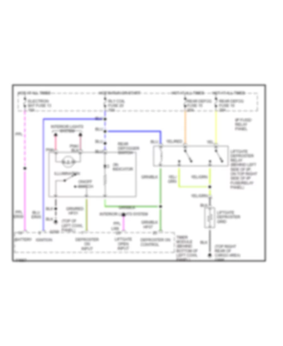
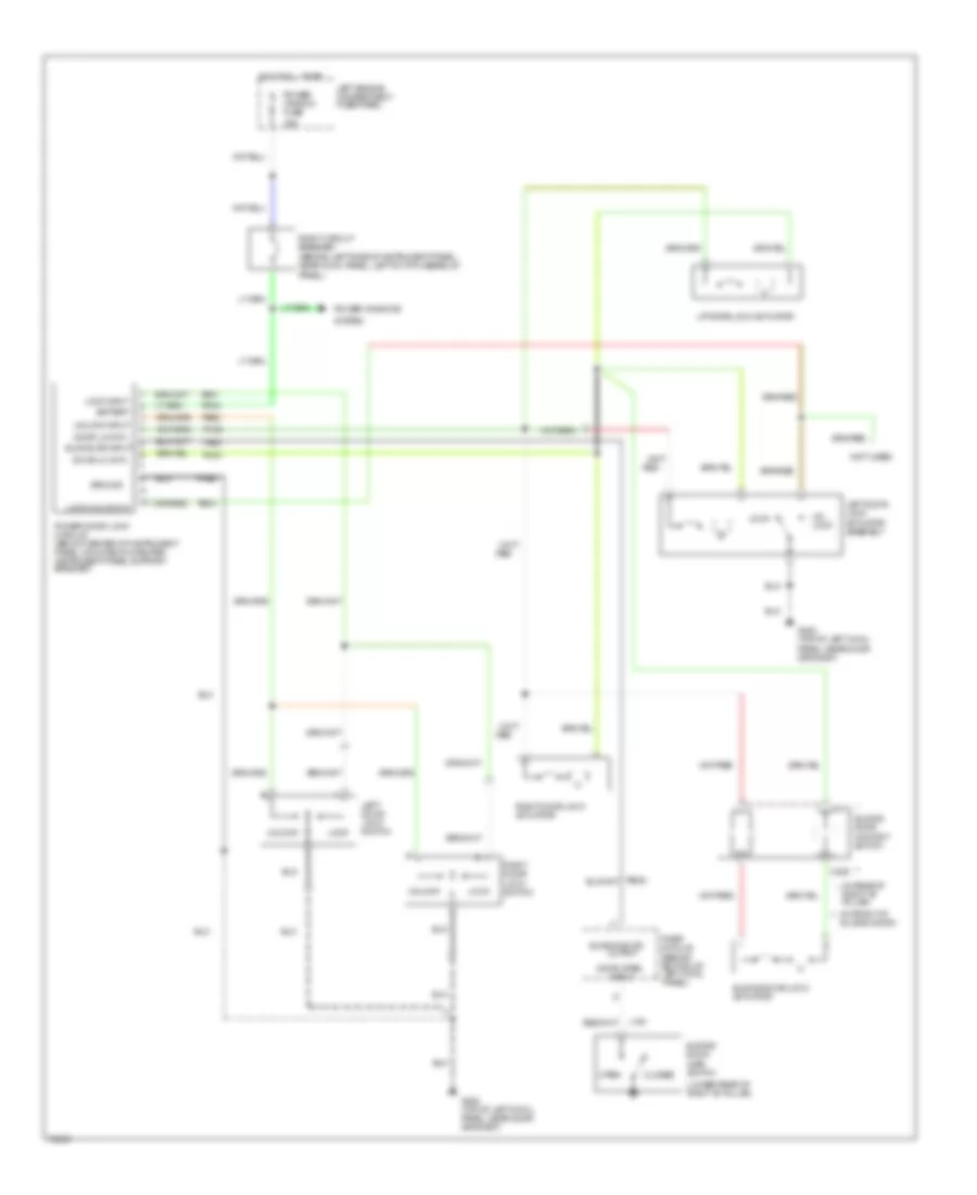
DEFOGGERS
Defogger Wiring Diagram for Mercury Villager LS 1995
List of elements for Defogger Wiring Diagram for Mercury Villager LS 1995:
- (top of left cowl panel)
- (top right rear of cargo area) g998
- Battery
- Defroster on control
- Defroster on input
- Electron bat fuse 13 10a
- Er05
- Er09
- G200
- Hf01
- Hf07
- Hot at all times
- Hot in run or start
- I/p fuse/ relay panel
- Ignition
- Illumination
- Interior lights system
- Li98
- Liftgate defroster grid
- Liftgate defroster relay (behind left side of i/p, on top right side of i/p fuse/relay panel)
- Liftgate open input
- On indicator
- On/off switch
- Pnk
- Rear defog fuse 15 20a
- Rear defog fuse 16 20a
- Rear defogger switch
- Rly coil fuse 20 10a
- Timer module (behind bottom of left cowl panel)
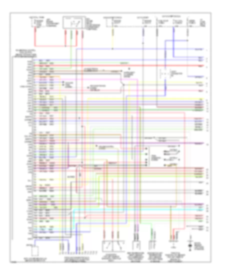
ENGINE PERFORMANCE
3.0L
3.0L, Engine Performance Wiring Diagrams (1 of 2) for Mercury Villager LS 1995
List of elements for 3.0L, Engine Performance Wiring Diagrams (1 of 2) for Mercury Villager LS 1995:
- mil
- (w/ electronic cluster only)
- 10a
- 15a
- Acr
- Air conditioning system (a/c relay)
- Anti-lock brake module (behind center of i/p)
- Av01
- Av02
- Av03
- Av04
- Av08
- Av12
- Av14
- Av15
- Av16
- Av17
- Av18
- Av19
- Av20
- Av21
- Av22
- Av23
- Av27
- Av29
- Av30a
- Av31a
- Av32
- Av33
- Av34
- Av36
- Av37
- Av38a
- Av40
- Av44
- Av46a
- Av47
- Av51
- Av52
- Av53
- Av54
- Av55
- Av59
- Av60
- Av62
- Av63
- Av64
- Avo5
- Avo7
- Ckp
- Ckpref
- Cooling fans system
- Cruise control system
- Data link connector (dlc) (left side of i/p, on bottom of i/p fuse/relay panel)
- Dlc
- Dtc
- Ect
- Egr temperature (egrt) sensor (on underside of throttle body, air intake)
- Egrc
- Egrt
- Engine cont 3
- Engine cont 7
- Engine cont fuse 25a
- Engine coolant temperature (ect) sensor (top right rear
- Engine, on throttle body)
- Ep13
- Ep57
- Ep58
- Ep66
- Epo6
- Es39
- Es48
- Es90
- Fa06
- Fa12
- Ffs
- Fpr
- Fuel pump fuse 8
- Gnd
- Ha41
- Ha45
- Hfan1/hfan2
- Ho2s
- Hot at all times
- Hot in start
- Hot in start or run
- Hps
- I/p fuse/ relay panel
- Iac
- Idl+
- Idl-
- Idle switch (top left rear of engine on throttle body)
- Ignc
- Ing
- Ings
- Inj1
- Inj2
- Inj3
- Inj4
- Inj5
- Inj6
- Instrument clusters system
- Joint connector #2
- Kapwr
- Knock sensor (left side of engine)
- Left engine compartment fuse/panel
- Lfan
- Maf+
- Maf-
- Meter fuse 21
- Nca
- Nr01
- Of engine)
- Pcm power relay (in left engine compartment fuse panel)
- Pcmr
- Pnk
- Pnps
- Powertrain control module (pcm) (behind top right side of i/p, behind glow box)
- Psp
- Red
- Rly coil fuse 20
- Rpm
- Sigrtn
- Tcm (tp)
- Throttle positiion (tp) sensor (top left rear of
- Tran- smissions system
- Vpwr
- Vref
- Vss
- Vst
- Zy13
- Zy34
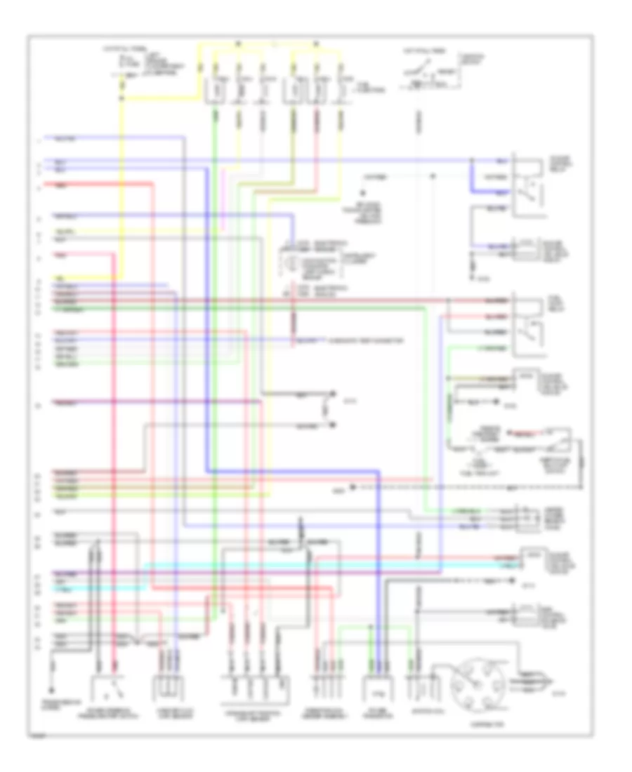
3.0L, Engine Performance Wiring Diagrams (2 of 2) for Mercury Villager LS 1995
List of elements for 3.0L, Engine Performance Wiring Diagrams (2 of 2) for Mercury Villager LS 1995:
- (analog)
- (electronic)
- 25a
- Acc
- Air condi- tioning system (a/c high press sw)
- C268
- C276
- Ckp out
- Ckp ref
- Crankshaft position (ckp) sensor
- Diagnostic test connector
- Distributor
- Egr control solenoid valve
- Fuel injectors
- Fuel pump
- Fuel pump relay
- Fuel tank unit
- G102
- G110
- G114
- G119
- G200
- Gnd
- Heated oxygen sensor (ho2s)
- Hot at all times
- Idle air control (iac) sole- noid #1
- Idle air control (iac) sole- noid #2
- Idle air control (iac) sole- noid #3
- Idle air control relay
- Ignitiion switch
- Ignition coil
- Inertia fuel shut-off switch
- Inj fuse
- Instrument cluster
- Left engine compartment fuse/panel
- Lock
- Malfunction indicator lamp "check engine"
- Mass air flow (maf) sensor
- Nca
- Passive restraint system
- Pnk
- Power steering pressure (psp) switch
- Power transistor
- Pwr in
- Red
- Resistor/con- denser assembly
- Run
- Start
- Transmissions system
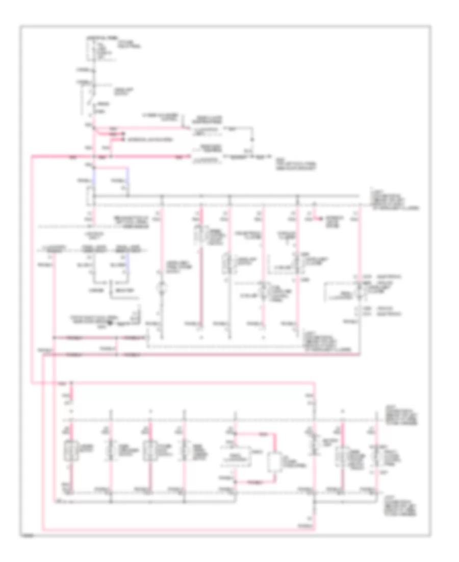
EXTERIOR LIGHTS
Exterior Light Wiring Diagram (1 of 2) for Mercury Villager LS 1995
List of elements for Exterior Light Wiring Diagram (1 of 2) for Mercury Villager LS 1995:
- (analog) (digital)
- (digital) (analog)
- C224
- C270 c276
- C276 c270
- Combination switch (top of steering column)
- Diode junction box (top left side of i/p, taped to main harness)
- Electron ign fuse 26 10a
- Flasher module (behind left side of i/p, right of steering column)
- Flasher output
- G102 (left rear of engine compartment, on side of strut tower)
- G203 (top of right cowl panel, near door grommet)
- G402 (above left rear wheel well, above connector bracket)
- G409 (left rear corner of cargo area)
- G410 (right rear corner of cargo area)
- Ground
- Ground distribution system
- Hazard flasher (top left side of i/p, right of cluster)
- Hazard fuse 17 15a
- Hot at all times
- Hot in start or run
- I/p fuse/relay panel
- Ignition/battery
- Illimination lamp
- Instrument cluster
- Interior lights system (instrument illumination)
- Lbe7
- Lbo3
- Lbo4
- Left
- Left backup lamp
- Left front turn lamp
- Left rear turn/ hazard lamp
- Left turn indicator
- Nca
- Off
- Pnk
- Right
- Right backup lamp
- Right front turn lamp
- Right rear turn/ hazard lamp
- Right turn indicator
- Transmission range position sensor (left side of engine, on front of transaxle)
- Transmission system (transmission control module pin #20)
- Turn fuse 22 10a
- Zy20
Exterior Light Wiring Diagram (2 of 2) for Mercury Villager LS 1995
List of elements for Exterior Light Wiring Diagram (2 of 2) for Mercury Villager LS 1995:
- (above left rear well, above connector bracket)
- (left rear of cargo area)
- (not used)
- A/light (tail) relay
- Anti-lock brake system
- Battery
- Boo input
- Brake on/off switch (top of brake pedal support)
- C220
- C224
- C258
- Combination switch (top of steering column)
- Courtesy lights system (underhood lamp)
- Cruise control system
- Front grill a lamp relay
- Front grill lamp relay
- Front grill lamps diode
- G102 (left rear of engine compartment, on side of strut tower)
- G402
- G409 (left rear corner of cargo area)
- G410 (right rear corner of cargo area)
- Grill trail fuse 20a
- Grille illumination lamps
- Ground
- Ground distribution system
- Head
- Headlamp switch
- High mount stop lamps
- Hot at all times
- I/p fuse/relay panel
- Lb31
- Lb32
- Left front park/ cornering lamp
- Left engine compartment fuse panel
- Left engine compartment relay block
- Left front marker lamp
- Left license lamp
- Left rear marker lamp
- Left rear park/ stop lamp
- Left right
- Left turn in
- Left turn out
- Lq04
- Lq21
- Lq25
- Lq26
- Lqe1
- Nca
- Off
- Park
- Pnk
- Right engine compartment relay block
- Right front marker lamp
- Right front park/ cornering lamp
- Right license lamp
- Right rear marker lamp
- Right rear park/ stop lamp
- Rt turn in
- Rt turn out
- Shift interlock system
- Stop lamp fuse 24 15a
- Tail lamp fuse 19 15a
- Trailer tow connector (optional)
- Trailer tow connector (under left rear of vehicle)
- Trailer tow control unit
- W/ autolamps/ delayed exit
- W/ trailer option
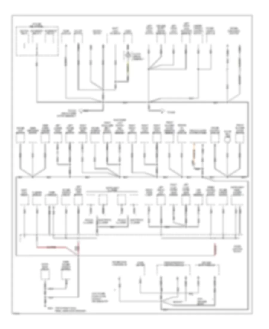
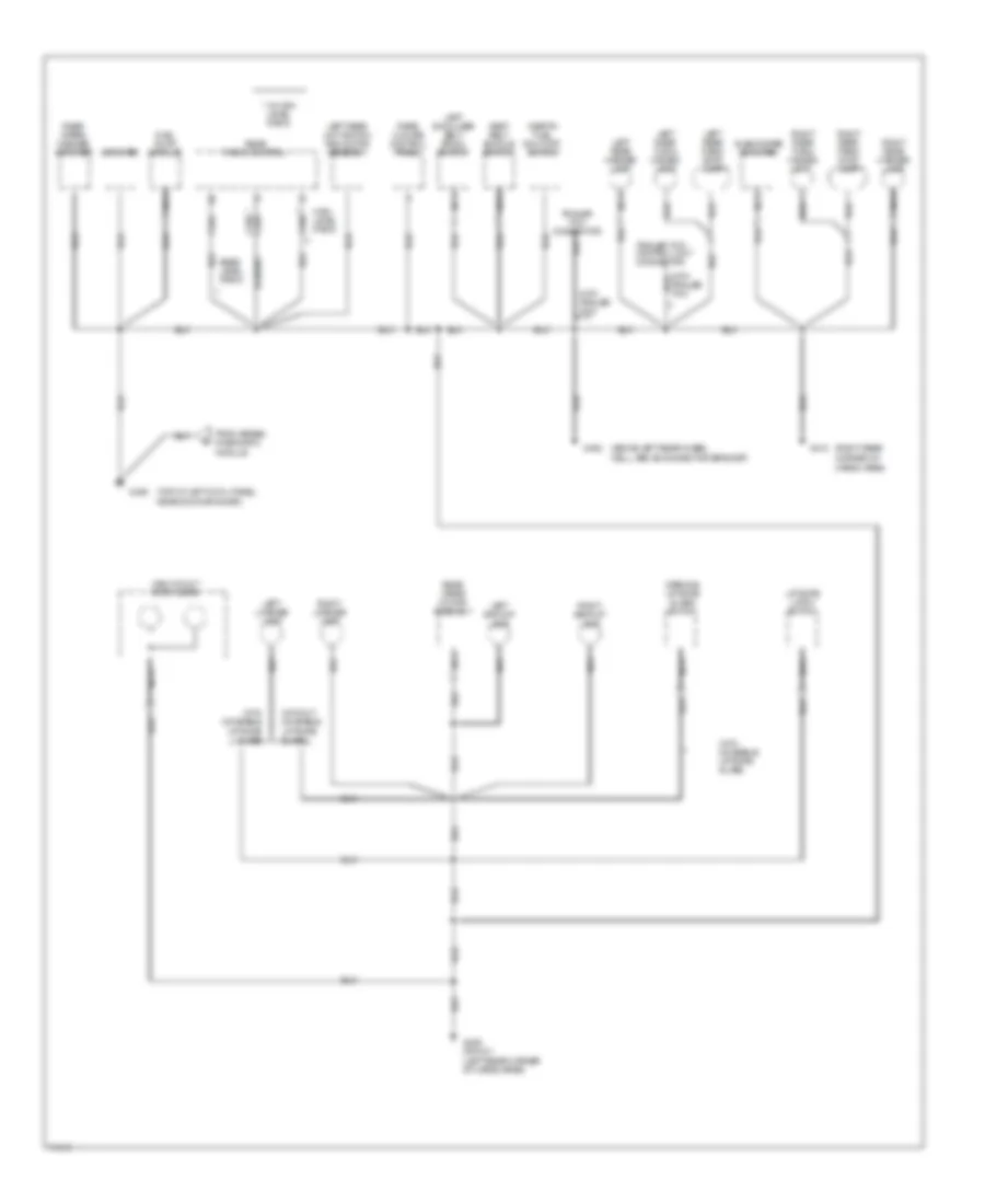
GROUND DISTRIBUTION
Ground Distribution Wiring Diagram (1 of 3) for Mercury Villager LS 1995
List of elements for Ground Distribution Wiring Diagram (1 of 3) for Mercury Villager LS 1995:
- (left front side of engine)
- (left rear of engine compartment on side of strut tower)
- (left rear of engine compartment, on side of strut tower)
- (lower left front of engine comparment, below left engine compartment fuse panel)
- (right rear of engine compartment,
- (top left front of engine, near fuel injector 6)
- A/c comp- ressor clutch coil
- A/c high pressure switch
- Anti-lock brake control module
- Battery
- Brake fluid level switch
- Bulb check relay
- C134
- C135
- C136
- C138
- C268
- C270
- C274
- Cooling fan motor
- Crankshaft position sensor
- Crankshaft position sensor shield
- Data link connector
- Daytime running lamps module
- Engine compart- ment lamp
- From i/p fuse/relay a
- Front grille lamps diode
- Front wiper motor assembly
- G102
- G103
- G103 (center of right fender apron)
- G108
- G110
- G111 (left side of engine compartment, below battery tray)
- G112
- G201 (below center of i/p, on right side of center i/p
- G402 (above left rear wheel well, above connector bracket)
- Generator/ voltage regulator
- Grille lamp relay
- Heated oxygen sensor
- Heated oxygen sensor shield
- Idle air control solenoid #1
- Idle air control solenoid #3
- Inhibit relay
- Instrument cluster
- Instrument cluster (analog)
- Knock sensor shield
- Left front marker lamp
- Left front park/ cornering lamp
- Left front turn lamp
- Left front wheel speed sensor shield
- Left headlamp
- Left headlamp relay
- Left rear wheel speed sensor shield
- Mass air flow sensor shield
- Nca
- On side of
- Outside air temperature sensor
- Panel
- Power steering pressure switch
- Power transistor
- Powertrain control module
- Rear engine coolant valve solenoid
- Right front marker lamp
- Right front park/ cornering lamp
- Right front turn lamp
- Right front wheel speed sensor shield
- Right headlamp
- Right headlamp relay
- Right rear wheel speed sensor shield
- Speed control hold relay
- Strut tower)
- Support brace)
- Throttle position sensor shield
- Trans- mission control module
- Transaxle control module
- Vehicle speed sensor
- W/ analog cluster
- W/ electronic cluster
- Washer fluid level switch
- Wiper/washer amplifier assembly
- With abs
- Without daytime running lamps
Ground Distribution Wiring Diagram (2 of 3) for Mercury Villager LS 1995
List of elements for Ground Distribution Wiring Diagram (2 of 3) for Mercury Villager LS 1995:
- (front wiper motor assembly)
- (top of right cowl panel, near door grommet)
- Accessory relay 1
- Accessory relay 2
- Air bag
- Analog cluster
- And motor assembly
- Blower
- Box lamp
- C2003
- C2004
- C203
- C219
- C221
- C223
- C225
- C266
- C270
- C274
- C276
- Cigar lighter
- Clock-
- Control module
- Control switch
- Cruise
- Diagnostic monitor
- Diode junction block
- Door jamb switch
- Door latch switch
- Door lock switch
- Electronic cluster
- Engine
- Flasher module
- Front
- Front climate control panel
- Front dome lamp
- Front limit switch
- G203
- Glove
- Gnd
- Horn switch
- I/p fuse/ relay panel
- Ignition relay
- Ignition switch
- Inated visor mirror
- Instrument cluster
- Instrument panel dimmer switch
- Keyless entry
- Keyless entry module
- Keypad assembly
- Latch switch
- Left
- Left door
- Left front limit switch
- Left illum-
- Level module
- Limit switch
- Lock actuator assembly
- Lock solenoid
- Lock switch
- Lumbar pump motor
- Map lamp assembly
- Master window
- Moon-
- Motor resistor assembly
- Motor switch
- Nca
- O/d off switch
- Oil
- Passive restraint control module
- Power
- Power antenna module
- Power door lock module
- Power e-at switch
- Power mirror switch
- Power seat switch
- Power window control
- Power window relay
- Rear
- Rear defogger switch
- Right
- Right illum-
- Right rear
- Roof relay
- Shift
- Shift lock relay
- Shoulder belt spool switch
- Speed control on/off switch
- Spring assembly
- Timer module
- To g103
- To g200
- Window module
- Wiper/ washer switch
- With keyless entry
- With power door locks, without keyless entry
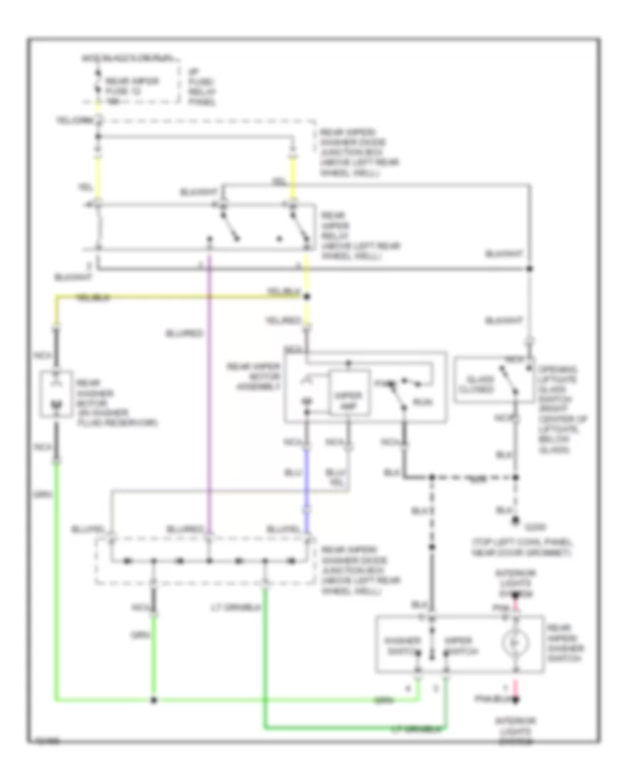
Ground Distribution Wiring Diagram (3 of 3) for Mercury Villager LS 1995
List of elements for Ground Distribution Wiring Diagram (3 of 3) for Mercury Villager LS 1995:
- (above left rear wheel well, above connector bracket)
- (left rear corner of cargo area)
- (right rear corner of cargo area)
- (top of left cowl panel, near door grommet)
- * c320
- * w/ high level radio
- Amplifier
- Base level radio
- C324
- From airbag diagnostic module
- Fuel pump module
- G200
- G402
- G409 or g411
- G410
- High level radio
- High mount stop lamps
- Inertia fuel shut-off switch
- Lamp
- Left backup lamp
- Left license lamp
- Left rear limit switch and motor assembly
- Left rear marker lamp
- Left rear park/ stop lamp
- Left rear turn/ hazard lamp
- Left shoulder belt spool switch
- Liftgate latch switch
- Nca
- Opening liftgate glass switch
- Rear climate control panel
- Rear radio control
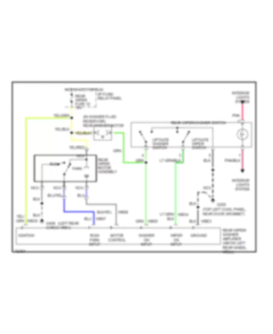
- Rear wiper motor assembly
- Rear wiper/ washer amplifier
- Right backup lamp
- Right license lamp
- Right rear marker lamp
- Right rear park/ stop lamp
- Right rear turn/ hazard
- Seat belt buckle switch
- Subwoofer amplifier
- Trailer tow connector
- Trailer tow control unit connector
- With moveable liftgate glass
- With trailer tow
- Without moveable liftgate glass
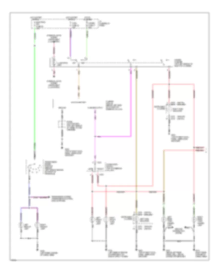
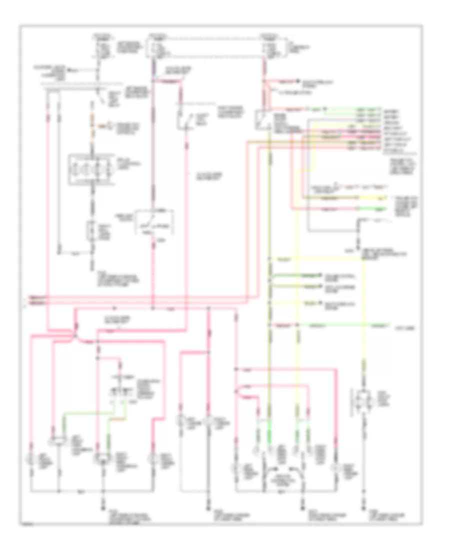
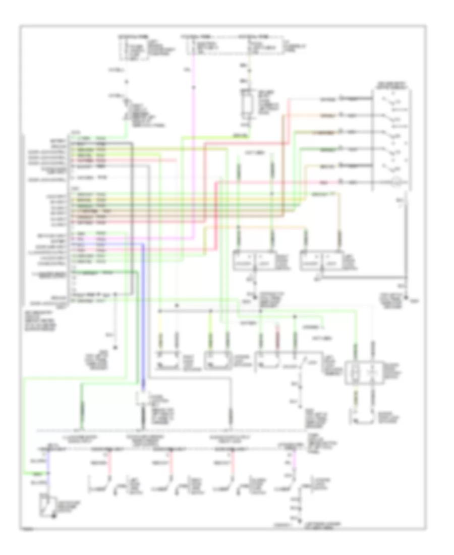
HEADLIGHTS
Headlamps Wiring Diagram, with Autolamps for Mercury Villager LS 1995
List of elements for Headlamps Wiring Diagram, with Autolamps for Mercury Villager LS 1995:
- (analog)
- (digital)
- (left rear of engine compartment, on side of strut tower) g102
- (top of right cowl panel, near door grommet) g203
- (w/ drl)
- (w/o drl)
- 100k ohm
- 3.3k ohm
- A/light (h/l) relay (right side of engine compartment, in right engine compartment relay block)
- A/light (tail) relay (right side of engine compartment, in right engine compartment relay block)
- Al01
- Al02
- Autolamp ctrl
- Autolamp diode (behind top left side of i/p, taped to front harness)
- Autolamp module (behind top right side
- Autolamp on input
- Autolamp sensor (top right side of i/p, near windshield)
- Battery
- C133
- C135
- C266
- C276
- C285
- Combination switch
- Daytime running lamps (drl) module (right side of engine compartment, on front of strut tower)
- Delayed exit input
- Delayed exit rehostat
- Diode junction box (behind top left side of i/p, taped to main harness)
- Exterior lights system
- Flash-to-pass
- Fuse 19 tail lamp fuse 15a
- Fuse 20 rly coil fuse 10a
- Fuse 26 electron ignition fuse 10a
- G102 (left rear of engine compartment, on side of strut tower)
- G203 (top of right cowl panel, near door grommet)
- H/lamp left fuse 15a
- H/lamp right fuse 15a
- Head
- Headlamp switch
- Headlamps circuit (w/ drl)
- High beam
- High beam indicator
- Hot at all times
- Hot in start or run
- I/p fuse/ relay panel (behind left side of, left of steering column)
- Ign
- Instrument cluster
- Instrument panel dimmer switch
- Left engine compartment fuse panel (left side of engine compartment, left of battery, on fender apron)
- Left headlamp
- Left headlamp relay (right side of engine compartment, in right engine compartment relay block)
- Lx01
- Lx02
- Lx03
- Lx04
- Lx05
- Lx06
- Nca
- Of i/p)
- Off
- Off/on control
- Park
- Pnk
- Pr06
- Pr07
- Pr08
- Ref ctrl
- Right headlamp
- Right headlamp relay (left front of engine compartment, in left engine compartment relay block)
- Sensor input
- W/ drl
- W/ drl only
- W/o drl
Headlamps Wiring Diagram, with DRL for Mercury Villager LS 1995
List of elements for Headlamps Wiring Diagram, with DRL for Mercury Villager LS 1995:
- (analog)
- (center of right fender apron) g103
- (digital)
- (left rear of engine compartment on side of strut tower) g102
- (top of right cowl panel, near door grommet) g203
- Battery
- Brake fluid level switch (left rear of engine compartment, on brake fluid reservoir)
- Brake warning indicator
- C266
- C268
- C276
- Ci33
- Ci35
- Combination switch
- Daytime running lamps (drl) module (right side of engine compartment, on front of strut tower)
- Diode junction box (behind top left side of i/p, taped to main harness)
- Flash-to-pass
- Fuse 20 rly coil 10a
- Fuse 21 meter fuse 10a
- Fuse 3 engine cont 5a
- G102 (left rear of engine compartment, on side of strut tower)
- Gen input
- Generator/ voltage regulator (lower right front of engine)
- Gnd
- H/lamp left 15a
- H/lamp right 15a
- Head
- Headlamp switch
- Headlamps circuit (w/ auto- lamps)
- High beam
- High beam indicator
- High beam on in
- Hot at all times
- Hot in start
- Hot in start or run
- I/p fuse relay panel (behind left side of i/p, left of steering column)
- I/p fuse/ relay panel (behind left side of i/p, left of steering column)
- Ign input
- Instru- ment cluster
- Instrument cluster (bulb check relay)
- Left engine compartment fuse panel (left side of engine compartment, left of battery, on fender apron)
- Left hdlp ctrl
- Left headlamp
- Left headlamp relay (right side of engine compartment, in right engine compartment relay block)
- Lights on input
- Off
- Park
- Park bk sw in
- Park brake switch (on park brake assembly)
- Pr01
- Pr02
- Pr03
- Pr04
- Pr05
- Pr06
- Pr07
- Pr08
- Pr09
- Pr11
- Pr12
- Pre1
- Right hdlp ctrl
- Right headlamp
- Right headlamp relay (left front of engine compartment, in left engine compartment relay block)
- Start input
- W/ auto- lamps only
- W/ autolamps only
Headlamps Wiring Diagram, without DRL for Mercury Villager LS 1995
List of elements for Headlamps Wiring Diagram, without DRL for Mercury Villager LS 1995:
- (analog)
- (digital)
- (left rear of engine compartment, on side of strut tower) g102
- (top of right cowl panel, near door grommet) g203
- C266
- C276
- Combination switch
- Flash-to-pass
- H/lamp left fuse 15a
- H/lamp right fuse 15a
- Head
- Headlamp switch
- Headlamps circuit (w/ auto- lamps)
- High beam
- High beam indicator
- Hot at all times
- Instrument cluster
- Left engine compartment fuse panel (left side of engine compartment, left of battery, on fender apron)
- Left headlamp
- Left headlamp relay (right side of engine compartment, in right engine compartment relay block)
- Off
- Park
- Right headlamp
- Right headlamp relay (left front of engine compartment, in left engine compartment relay block)
- W/ autolamps only
HORN
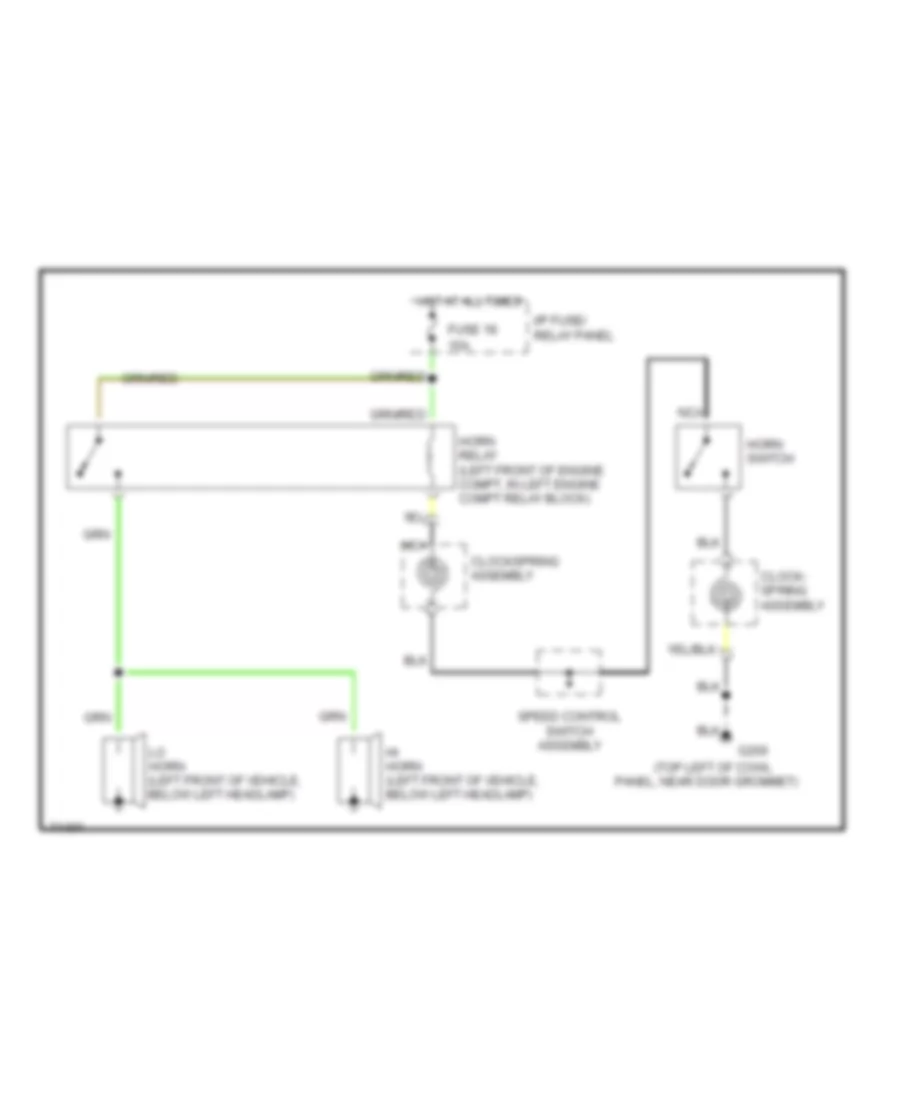
Horn Wiring Diagram for Mercury Villager LS 1995
List of elements for Horn Wiring Diagram for Mercury Villager LS 1995:
- (top left of cowl
- 15a
- Clock- spring assembly
- Clockspring assembly
- Fuse 18
- G200
- Hi horn (left front of vehicle, below left headlamp)
- Horn relay (left front of engine compt, in left engine compt relay block)
- Horn switch
- Hot at all times
- I/p fuse/ relay panel
- Lo horn (left front of vehicle, below left headlamp)
- Nca
- Panel, near door grommet)
- Speed control switch assembly
INSTRUMENT CLUSTER
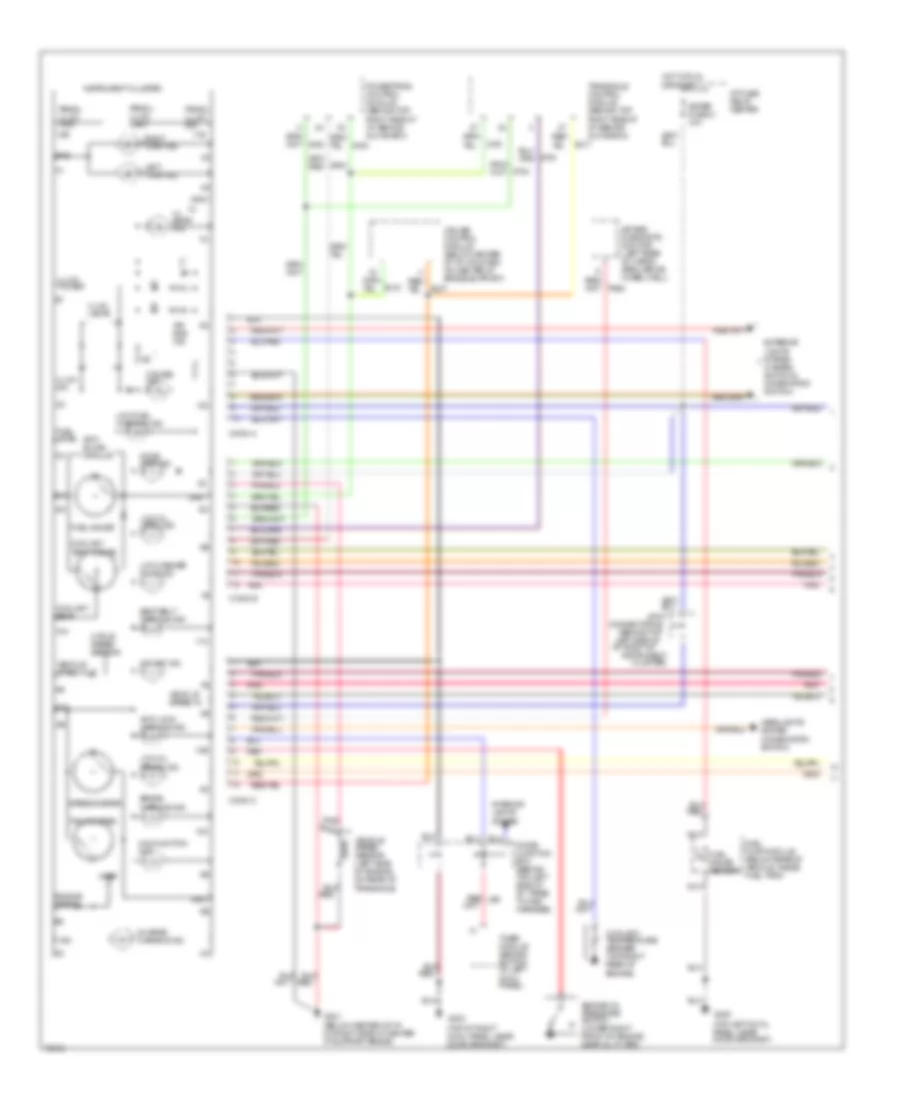
Instrument Cluster Wiring Diagram, Analog (1 of 2) for Mercury Villager LS 1995
List of elements for Instrument Cluster Wiring Diagram, Analog (1 of 2) for Mercury Villager LS 1995:
- (behind top left side of i/p, right of
- (below center of i/p, on right side of center i/p support brace)
- (top left cowl panel, near door grommet)
- (top of right cowl panel, near door grommet)
- 10a
- 10b
- 10c
- 11b
- 11c
- 12b
- 12c
- 2 pole speed sensor
- Air bag diagnostic monitor (left rear of cargo area, above wheel well)
- Air bag ind.
- Anti- slosh module
- Anti-lock warning ind.
- Av02
- Av32
- Brake warning ind.
- Charge warning ind.
- Cluster)
- Conn a
- Conn b
- Conn c
- Connector #2
- Coolant temp.
- Coolant temp. gauge
- Coolant temperature sender (top right rear of engine)
- Cruise control module (below center of i/p, mounted on center i/p brace support)
- Cruise ind.
- Diode junction box (behind top left side of i/p, taped to main harness)
- Door ajar ind.
- Ej07
- Ej10
- Ej17
- Engine oil pressure switch (lower right front of engine, near oil filter)
- Engine speed
- Exterior lights system (hazard switch & combination switch)
- Fuel gauge
- Fuel gauge sender
- Fuel level
- Fuel pump module (below rear of vehicle, inside fuel tank)
- G200
- G201
- G203
- Gnd
- Headlights system (combination switch)
- Hi beam ind.
- Hot in run or start
- I/p fuse/ relay center
- Ign
- Illum. dim
- Illum. lamps
- Illum. power
- Instrument
- Instrument cluster
- Interior lights system
- Joint
- Left turn ind.
- Low fuel warning ind.
- Low oil level ind.
- Low oil press. ind.
- Low washer fluid ind.
- Malfunction ind.
- Meter fuse 21 10a
- Nca
- Nr01
- O/d off ind.
- Pnk
- Powertrain control module (behind top right side of i/p, behind glove box)
- Prndl illum. dim
- Prndl illum. lamp
- Prndl illum. pwr
- Ps03
- Red
- Red/ li98
- Right turn ind.
- Seat belt warning ind.
- Speedometer
- Tachometer
- Timer module (behind bottom of left cowl panel)
- Transaxle control module (behind top right side of i/p, behind glove box)
- V ref
- Vehicle speed in
- Vehicle speed out
- Vehicle speed sensor (left side of engine, on rear of transaxle)
- Zy03
- Zy24
- Zy27
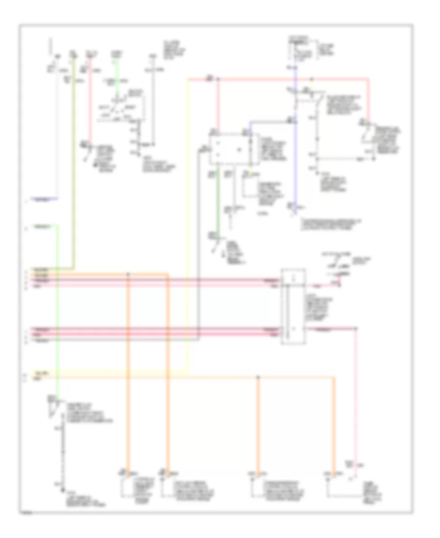
Instrument Cluster Wiring Diagram, Analog (2 of 2) for Mercury Villager LS 1995
List of elements for Instrument Cluster Wiring Diagram, Analog (2 of 2) for Mercury Villager LS 1995:
- (below center of i/p, mounted on center i/p support brace)
- (left rear of engine compt, on brake fluid reservoir)
- (left rear of engine compt, on side of strut tower)
- (lower right front of engine compt, on washer fluid reservoir)
- (lower right front of engine)
- (on park brake assembly)
- (top of right cowl panel, near door grommet)
- Acc
- Anti-lock brake control module
- Brake fluid level switch
- Bulb check relay (left front of engine compt, in left engine compt relay block)
- Daytime running lamps module (right side of engine compt, on front of strut tower)
- Diode junction box (behind top left side of i/p, taped to main harness)
- Engine oil level switch
- G102
- G203
- Generator/ voltage regulator (lower right front of engine)
- Gnd
- Head
- Headlamp switch
- Hot at all times
- Hot in run or start
- Hydraulic actuator assembly (right front of engine compt)
- I/p fuse/ relay center
- Ig91
- Ign
- Ignition switch
- Ind. ctrl
- Joint connector #2 (behind top left side of i/p, right of instrument cluster)
- Lock
- Np02
- Np04
- Np05
- Off
- Oil level module (behind top right side of i/p)
- Oil lvl input
- Park
- Park brake switch
- Passive restraint control module
- Pnk
- Rly coil fuse 20 10a
- Run
- Start
- Start input
- Timer module (behind bottom of left cowl panel)
- W/ drl
- Washer fluid level switch
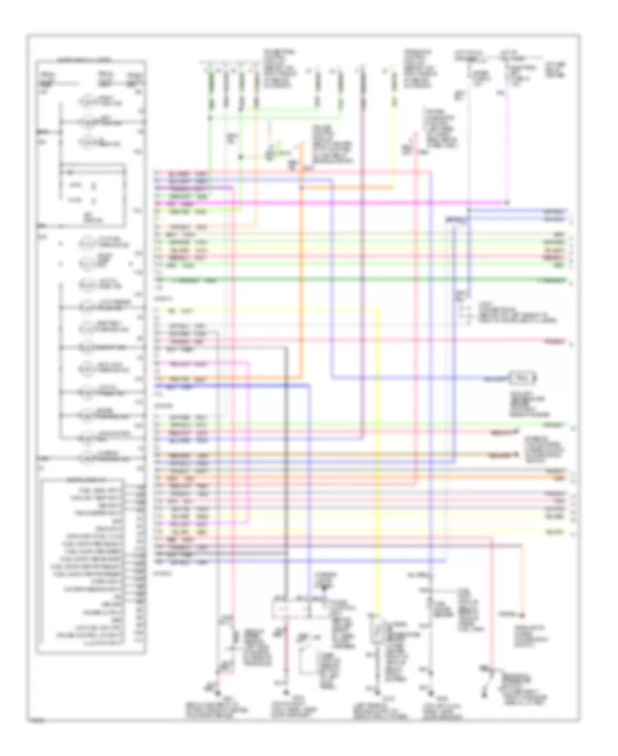
Instrument Cluster Wiring Diagram, Electronic (1 of 2) for Mercury Villager LS 1995
List of elements for Instrument Cluster Wiring Diagram, Electronic (1 of 2) for Mercury Villager LS 1995:
- (below center of i/p, on right side of center i/p support brace)
- (left rear of engine compt, on side of strut tower)
- (top left cowl panel, near door grommet)
- (top of right cowl panel, near door grommet)
- 10a
- 10b
- 10c
- 11a
- 11b
- 11c
- 12a
- 12c
- 13a
- 13c
- 14a
- 14c
- 15c
- 16c
- 17c
- 18c
- 19c
- Air bag diagnostic monitor (left rear of cargo area, above wheel well)
- Air bag ind.
- Anti-lock warning ind.
- Av02
- Av05
- Av32
- Bat
- Brake warning ind.
- Bs29
- C20
- Charge warning ind.
- Conn a
- Conn b
- Conn c
- Coolant temp input
- Coolant temperature sender (top right rear of engine)
- Cruise control module (below center of i/p, mounted on center i/p brace support)
- Cruise control on input
- Data input-fuel flow
- Digital display
- Dimmer output
- Diode junction box (behind top left side of i/p, taped to main harness)
- Door ajar ind.
- Ej07
- Ej10
- Ej17
- Electron bat fuse 13 10a
- Engine oil pressure switch (lower right front of engine, near oil filter)
- Exterior lights system (hazard switch & combination switch)
- Fuel computer eng/met
- Fuel computer reset
- Fuel computer select
- Fuel computer trip/reset
- Fuel computer trip/select
- Fuel gauge sender
- Fuel level input
- Fuel pump module (below rear of vehicle, inside fuel tank)
- G102
- G200
- G201
- G203
- Gnd
- Grd
- Headlights system (combination switch)
- Hi beam ind.
- Hot at all times
- Hot in run or start
- I/p fuse/ relay center
- Ig01
- Ig91
- Ig92
- Ign
- Illum dim input
- Instrument cluster
- Interior lights system
- Joint connector #2 (behind top left side of i/p, right of instrument cluster)
- La03
- Lb15
- Lb16
- Left turn ind.
- Low fuel ind ctrl
- Low fuel warning ind.
- Low oil level ind.
- Low oil press. ind.
- Low washer fluid ind.
- Ma01
- Ma02
- Ma03
- Ma04
- Ma06
- Ma07
- Ma11
- Ma12
- Ma14
- Ma15
- Ma16
- Ma17
- Ma20
- Ma41
- Mae1
- Mae2
- Malfunction ind.
- Md01
- Meter fuse 21 10a
- Mj01
- Mje2
- Nb01
- Nca
- Nf01
- Ni03
- Nm01
- Nn01
- Np04
- Nr01
- O/d off ind.
- O/s temp sensor input
- Outside air temperature sensor (lower center front of vehicle, below front bumper)
- Pnk
- Powertrain control module (behind top right side of i/p, behind glove box)
- Prndl illum. dim
- Prndl illum. lamp
- Prndl illum. pwr
- Ps03
- Red
- Red/ li98
- Right turn ind.
- Seat belt warning ind.
- Start input
- Tachometer input
- Timer module (behind bottom of left cowl panel)
- Transaxle control module (behind top right side of i/p, behind glove box)
- Vehicle speed sensor (left side of engine, on rear of transaxle)
- Vss grd
- Vss input
- Vss ouput
- Zy03
- Zy24
- Zy27
Instrument Cluster Wiring Diagram, Electronic (2 of 2) for Mercury Villager LS 1995
List of elements for Instrument Cluster Wiring Diagram, Electronic (2 of 2) for Mercury Villager LS 1995:
- (below center of i/p, mounted on center i/p support brace)
- (left rear of engine compt, on brake fluid reservoir)
- (left rear of engine compt, on side of strut tower)
- (lower right front of engine compt, on washer fluid reservoir)
- (lower right front of engine)
- (on park brake assembly)
- (top of right cowl panel, near door grommet)
- 0rg
- Acc
- Anti-lock brake control module
- Brake fluid level switch
- Bulb check relay (left front of engine compt, in left engine compt relay block)
- Daytime running lamps module (right side of engine compt, on front of strut tower)
- Diode junction box (behind top left side of i/p, taped to main harness)
- Engine oil level module (behind top right side of i/p)
- English/ metric
- Fuel computer control panel (left of steering column)
- G102
- G203
- Generator/ voltage regulator (lower right front of engine)
- Gnd
- Head
- Headlamp switch
- Hot at all times
- Hot in run or start
- Hydraulic actuator assembly (right front of engine compt)
- I/p fuse/ relay center
- Ig91
- Ign
- Ignition switch
- Illum.
- Ind. ctrl
- Joint connector #2 (behind top left side of i/p, right of instrument cluster)
- Lock
- Np02
- Np04
- Np05
- Off
- Oil level switch
- Oil lvl input
- Park
- Park brake switch
- Passive restraint control module
- Pnk
- Reset
- Rly coil fuse 20 10a
- Run
- Select
- Start
- Start input
- Timer module (behind bottom of left cowl panel)
- Trip reset
- Trip select
- W/ drl
- Washer fluid level switch
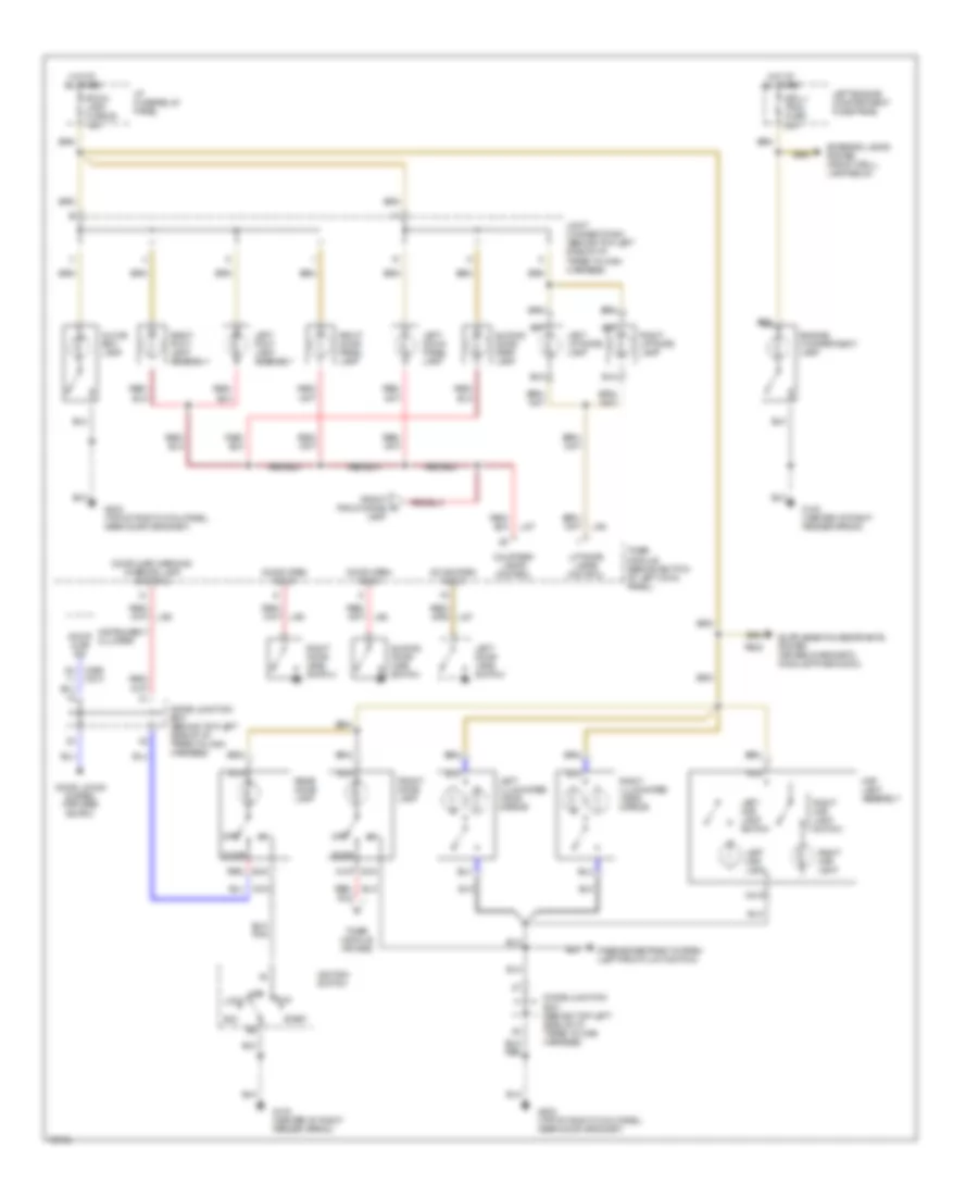
INTERIOR LIGHTS
Courtesy Lamps Wiring Diagram for Mercury Villager LS 1995
List of elements for Courtesy Lamps Wiring Diagram for Mercury Villager LS 1995:
- 8c c266 c274
- Acc
- Courtesy lamps control
- Diode junction box (behind top left side of i/p, taped to main harness)
- Door
- Door ajar ind
- Door ajar warning/ interior lamp control
- Door locks system (keyless entry)
- Door open input
- Engine compartment lamp
- Exterior lamps system (front grill lamp relay)
- Front dome lamp
- Front front dome a
- G103 (center of right fender apron)
- G203 (top of right cowl panel, near door grommet)
- Glove box lamp
- Grill/ trail fuse 20a
- Hot at all times
- I/p fuse/relay panel
- Ignition switch
- Instrument cluster
- Joint connector #1 (behind top left side of i/p, taped to main harness)
- Lamp
- Left door jamb switch
- Left door panel lamp
- Left engine compartment fuse panel
- Left foot lamp assembly
- Left illuminated visor mirror
- Left liftgate lamp
- Left map lamp
- Left map lamp switch
- Li87
- Li93
- Liftgate lamps control
- Lock
- Map lamp assembly
- Nca
- Off
- Passive restraint system (left front limit switch)
- Ps02
- Rear dome lamp
- Red
- Right door jamb switch
- Right door panel lamp
- Right foot lamp assembly
- Right illuminated visor mirror
- Right liftgate lamp
- Right map lamp
- Right map lamp switch
- Room lamp fuse 25 15a
- Run
- Sliding door ajar switch
- Sliding door step lamp
- Start
- Timer module (behind bottom of left cowl panel)
- Timer module (pin #26)
Instrument Illumination Wiring Diagram for Mercury Villager LS 1995
List of elements for Instrument Illumination Wiring Diagram for Mercury Villager LS 1995:
- (2) bulbs
- (4) bulbs
- (analog)
- (behind bottom of left cowl panel) timer module
- (electronic)
- (top of right cowl panel,
- Ashtray lamp
- Brighter
- C201
- C266
- C268
- C274
- C276
- Cd player (if equipped)
- Darker
- Exterior lights system
- Front climate control panel
- Fuel computer control panel
- G200 (top left cowl panel, near door grommet)
- G203
- Hazard switch
- Head
- Headlamp switch
- Hot at all times
- I/p fuse/ relay panel
- Illumination
- Illumination dimming
- Illumination lamp
- Instrument cluster
- Instrument panel dimmer switch
- Joint connector #1 (behind top left side of i/p, taped to main harness)
- Joint connector #2 (behind top left side of i/p, right of instrument cluster)
- Lights-on input
- Near door grommet)
- Panel lamps "bright" input
- Panel lamps "dark" input
- Park
- Pnk
- Power e-a/t switch
- Prndl illumination
- Radio
- Radio illumination
- Rear blower motor switch (front)
- Rear climate control panel
- Rear defogger switch
- Rear radio control
- Rear wiper/ washer switch
- Speed control on/off switch
- Tail lamp fuse 19 15a
- W/ rear a/c-heater control
- W/analog cluster
- W/electronic cluster
PASSIVE RESTRAINTS
Passive Restraint Wiring Diagram for Mercury Villager LS 1995
List of elements for Passive Restraint Wiring Diagram for Mercury Villager LS 1995:
- (top of left cowl panel, near door grommet)
- Activate chime input
- Activate chime output
- Activate lamp output
- Battery power input
- C223
- C225
- Electron ign fuse 26 10a
- Engine controls system (fuel tank unit)
- G200
- G200 (top of left cowl panel, near door grommet)
- G402 (above left rear wheel well, above connector bracket)
- Ground
- Hot at all times
- Hot in run or start
- I/p fuse/ relay panel
- Ignition power input
- Inertia fuel shut-off switch (behind bottom left cowl panel)
- Inertia fuel shutoff switch in
- Instrument cluster
- Left circuit breaker (left of i/p fuse/ relay panel)
- Left door latch switch
- Left door latch switch (on left front door latch assembly)
- Left engine compartment fuse panel
- Left front limit switch (in left "a" pillar, on track assembly)
- Left front limit switch input
- Left rear limit motor
- Left rear limit switch and motor assembly (in left "b" pillar)
- Left rear limit switch input
- Left shoulder belt spool sw
- Left shoulder belt spool switch (right side of left front seat)
- Logic ground
- Meter fuse 10a
- Nca
- Ni03
- Passive restraint control module (mounted on center i/p support bracket)
- Power window fuse 30a
- Pp01
- Pp02
- Pp03
- Pp04
- Pp05
- Pp07
- Pp08
- Pp09
- Pp10
- Pp11
- Pp12
- Pp13
- Pp14
- Pp15
- Pp17
- Pp18
- Pp20
- Pp21
- Pp22
- Pp23
- Pp25
- Ppe1
- Ppe2
- Ppe3
- Right door latch switch
- Right door latch switch (on right front door latch assembly)
- Right front limit switch
- Right front limit switch (in right "a" pillar, on track assembly)
- Right rear limit motor
- Right rear limit switch and motor assembly (in right "b" pillar)
- Right shoulder belt spool switch (lower left side of right front seat)
- Room lamp fuse 25 15a
- Rt rear limit switch
- Rt shoulder belt spool sw
- Seat belt warning lamp
- Seat belt warning lamp output
- Timer module (behind bottom of left cowl panel)
- Timer module chime output
- Warning chime (behind top left side of i/p)
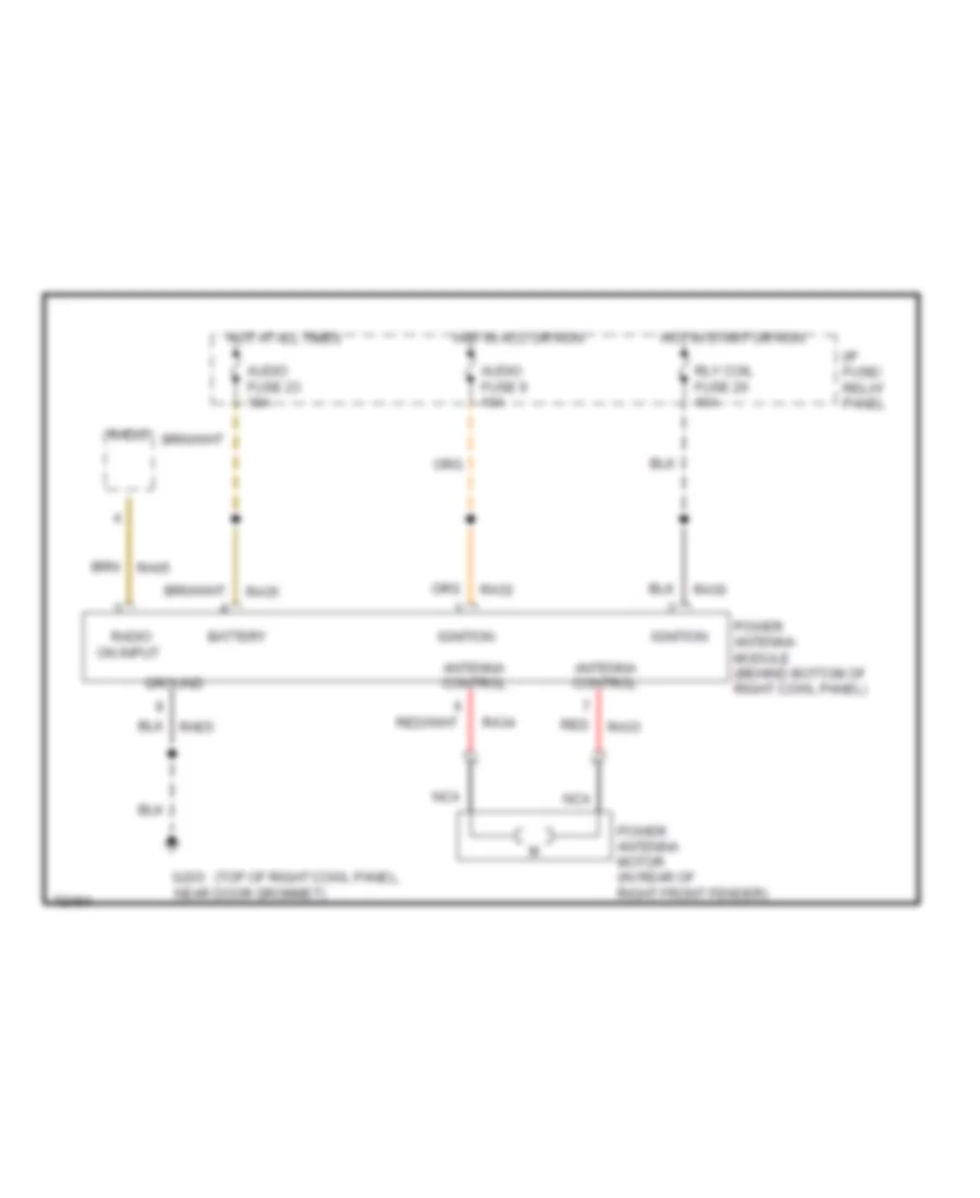
POWER ANTENNA
Power Antenna Wiring Diagram for Mercury Villager LS 1995
List of elements for Power Antenna Wiring Diagram for Mercury Villager LS 1995:
- (top of right cowl panel,
- Antenna control
- Audio fuse 23 10a
- Audio fuse 9 10a
- Battery
- G203 near door grommet)
- Ground
- Hot at all times
- Hot in acc or run
- Hot in start or run
- I/p fuse/ relay panel
- Ignition
- Nca
- Power antenna module (behind bottom of right cowl panel)
- Power antenna motor (in rear of right front fender)
- Ra05
- Ra30
- Ra32
- Ra33
- Ra34
- Ra35
- Radio
- Radio on input
- Rae5
- Red
- Rly coil fuse 20 10a
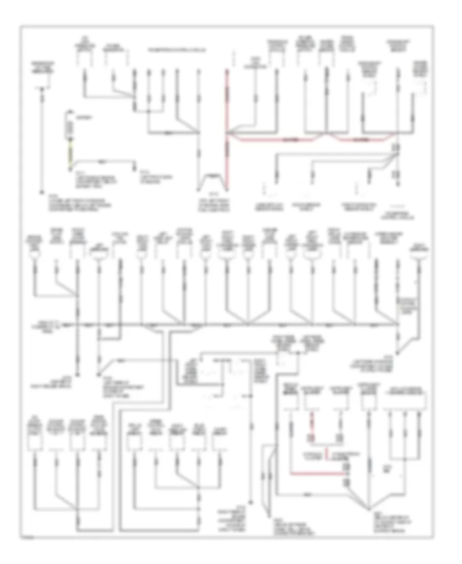
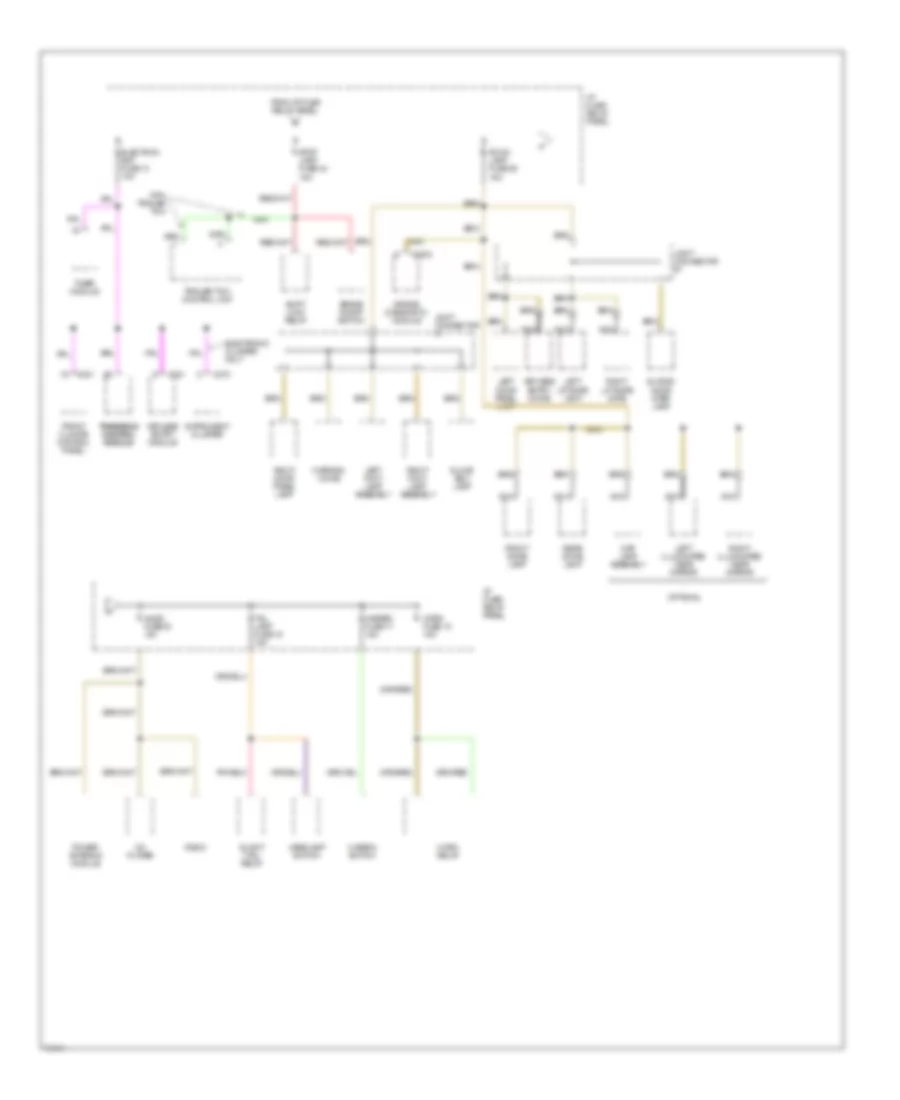
POWER DISTRIBUTION
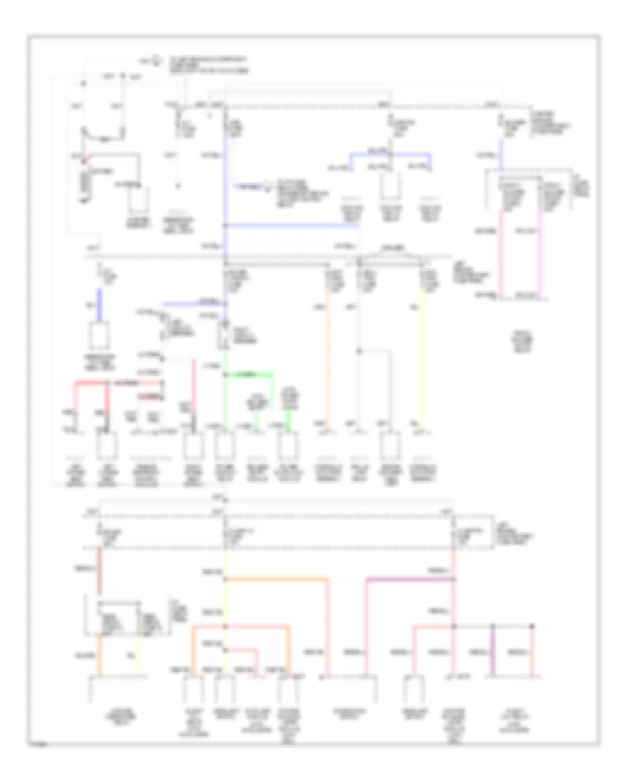
Power Distribution Wiring Diagram (1 of 4) for Mercury Villager LS 1995
List of elements for Power Distribution Wiring Diagram (1 of 4) for Mercury Villager LS 1995:
- (with autolamps)
- (with drl)
- A/light (h/l) relay
- Alt fuse 10a
- Alt fuse 120a
- Anti- skid fuse 20a
- Anti- skid fuse 30a
- Autolamp module
- Battery
- Blower fuse 65a
- C133
- C223
- Center engine compartment fuse panel
- Combination switch
- Cooling fan hi1 relay
- Cooling fan hi2 relay
- Cooling fan lo relay
- Daytime running lamps module
- Engine compart- ment lamp
- Front blower motor fuse 1 20a
- Front blower motor fuse 2 20a
- Front blower motor relay
- Generator/ voltage regulator
- Grill/ trail fuse 20a
- Grille lamp relay
- H/lamp lh fuse 15a
- H/lamp rh fuse 15a
- Headlamp switch
- Hydraulic actuator assembly
- I/p fuse/ relay panel
- Keyless entry module
- Left circuit breaker
- Left engine compartment fuse panel
- Left lumbar seat switch
- Left power seat switch
- Liftgate defroster relay
- Main fuse 100a
- Nca
- Passive restraint control module
- Power door lock module
- Power window fuse 30a
- Power window relay
- Rad fan fuse 65a
- Rear defog fuse 15 20a
- Rear defog fuse 16 20a
- Red
- Right circuit breaker
- Right power seat switch
- Rr def fuse 45a
- Starter assembly
- To i/p fuse/ relay panel (accessory relays 1 & 2 and ignition relay)
- To left engine compartment fuse panel (eng cont, ign sw, & inj fuses)
- With abs
- With keyless entry
- With power door locks
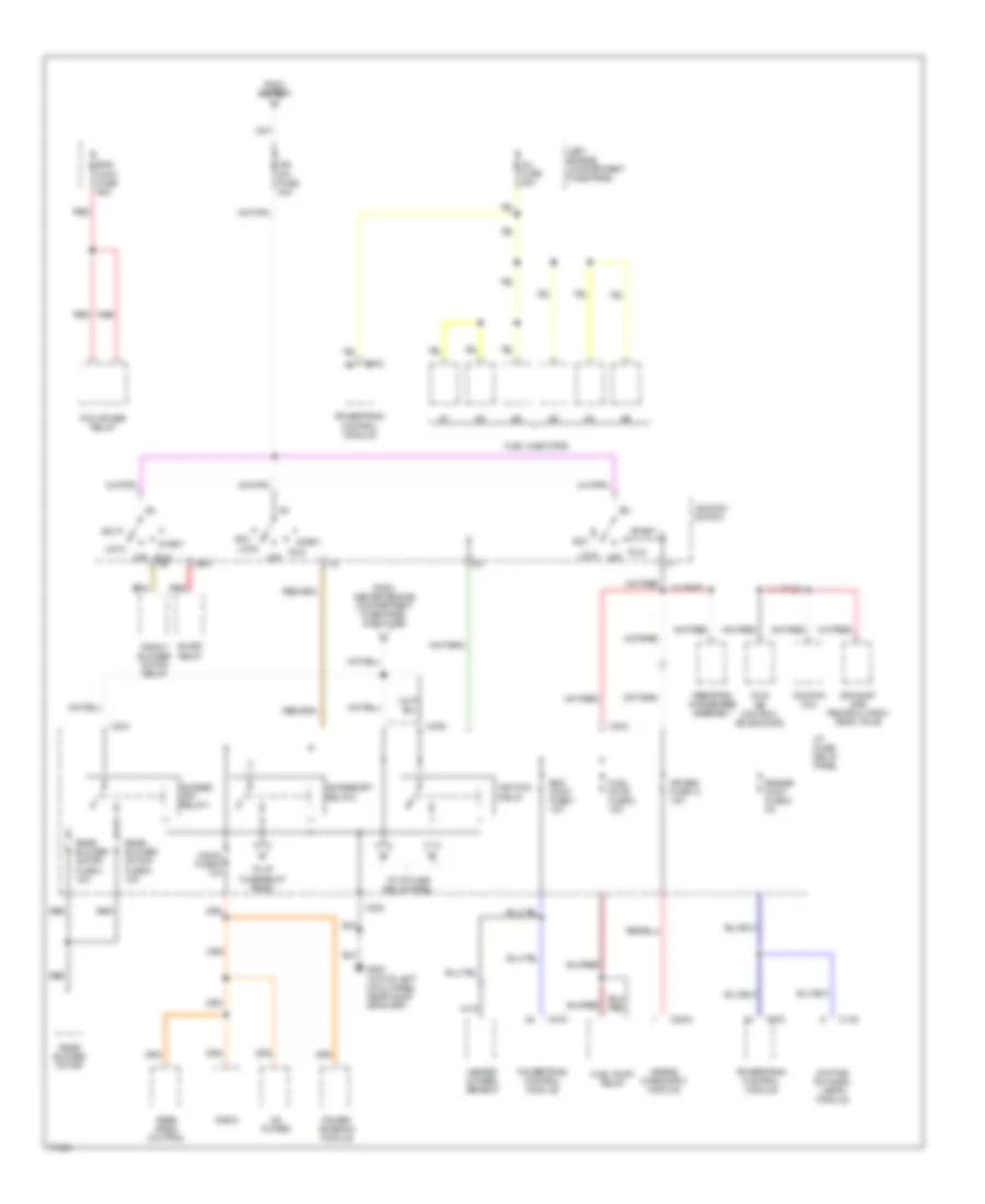
Power Distribution Wiring Diagram (2 of 4) for Mercury Villager LS 1995
List of elements for Power Distribution Wiring Diagram (2 of 4) for Mercury Villager LS 1995:
- Acc
- Access- ory relay 1
- Accessory relay 2
- Air bag fuse 14 10a
- Airbag diagnostic module
- Audio fuse 9 10a
- C135
- C2004
- C202
- C204
- C206
- C275
- Cd player
- Daytime running lamps module
- Eng cont fuse 25a
- Eng cont fuse 7 10a
- Engine cont fuse 3 5a
- Exhaust gas recirculation (egr) valve
- From battery
- From center engine compartment fuse panel (main fuse)
- Front blower motor relay
- Fuel injectors
- Fuel pump fuse 8 15a
- Fuel pump relay
- G200 (top of left cowl panel, near door grommet)
- Heated oxygen sensor
- I/p fuse/ relay panel
- Idle air control solenoid #2
- Ign sw fuse 30a
- Ignition coil
- Ignition relay
- Ignition switch
- Inhibit relay
- Inj fuse 25a
- Left engine compartment fuse panel
- Lock
- Nca
- Off
- Pcm power relay
- Power antenna module
- Powertrain control module
- Radio
- Rear blower motor
- Rear blower motor fuse 4 15a
- Rear blower motor fuse 5 15a
- Rear radio control
- Red
- Resistor/ condenser assembly
- Run
- Run a4
- Sta
- Start
- To i/p fuse/ relay panel
- To i/p fuse/relay panel
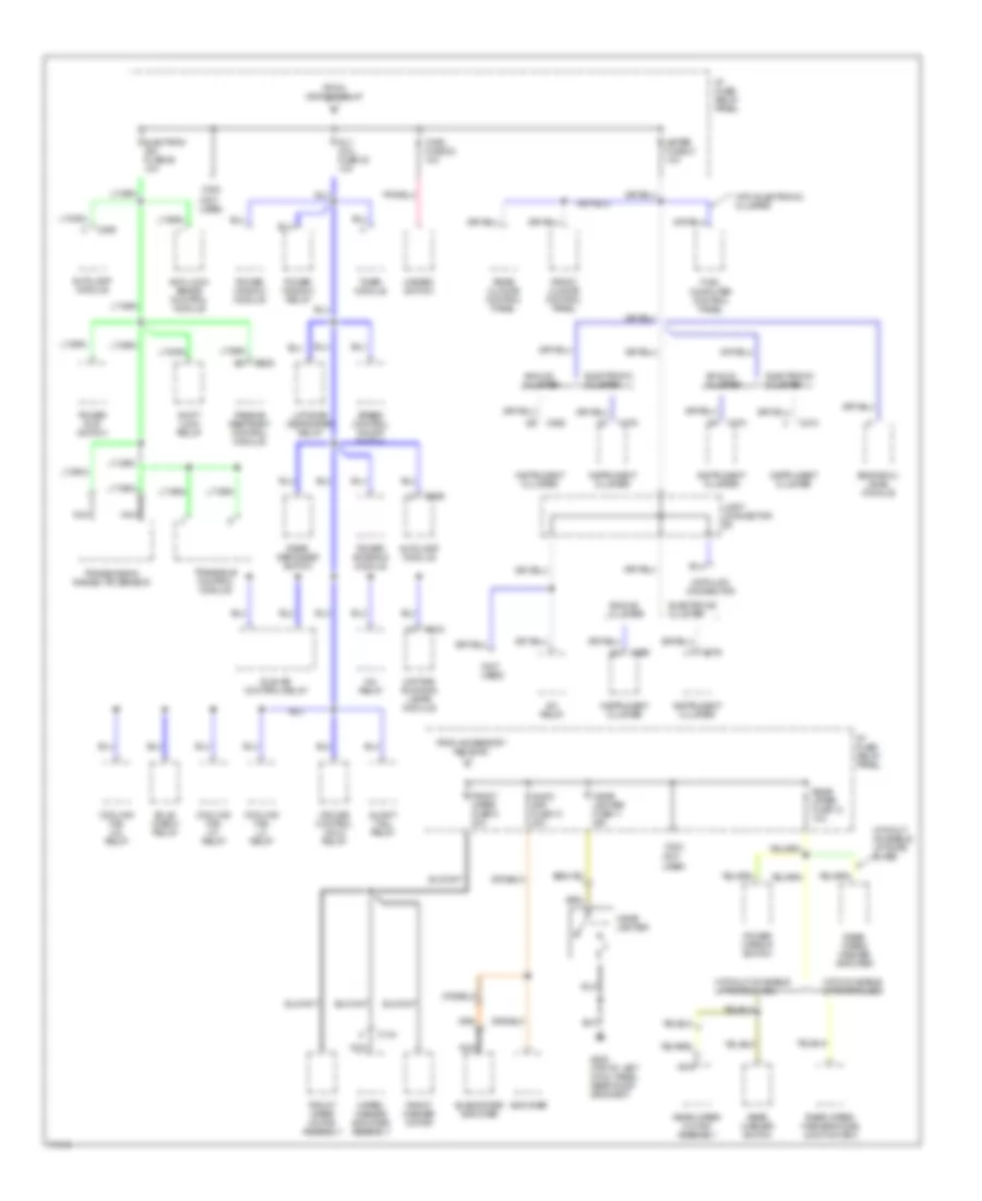
Power Distribution Wiring Diagram (3 of 4) for Mercury Villager LS 1995
List of elements for Power Distribution Wiring Diagram (3 of 4) for Mercury Villager LS 1995:
- (not used)
- A/c relay
- A/light (tail) relay
- Amplifier
- Analog cluster
- Anti-lock brake control module
- Audio amp fuse 10 20a
- Autolamp module
- Bulb check relay
- C133
- C134
- C202
- C204
- C225
- C259
- C266
- C268
- C270
- C274
- C276
- Cigar lighter
- Cigar lighter fuse 11 20a
- Cooling fan hi1 relay
- Cooling fan hi2 relay
- Cooling fan lo relay
- Cruise control hold relay
- Data link connector
- Daytime running lamps module
- Electron ign fuse 26 10a
- Electronic cluster
- Engine oil level module
- From accessory relay #2
- From ignition relay
- Front climate control panel
- Front washer motor
- Front wiper fuse 6 20a
- Front wiper motor assembly
- Fuel computer control panel
- G200 (top of left cowl panel near door grommet)
- Hazard switch
- I/p fuse/ relay panel
- Idle air control relay
- Instrument cluster
- Joint connector #2
- Liftgate defroster relay
- Meter fuse 21 10a
- Nca
- Passive restraint control module
- Power antenna module
- Power e-at switch
- Power mirror switch
- Power window module
- Power window relay
- Rear climate control panel
- Rear defogger switch
- Rear washer switch
- Rear wiper fuse 12 10a
- Rear wiper motor assembly
- Rear wiper/ washer amplifier
- Rear wiper/ washer diode junction box
- Rly coil fuse 20 10a
- Shift lock relay
- Speed control on/off switch
- Subwoofer amplifier
- Timer module
- Transaxle control module
- Transmission range (tr) sensor
- Turn fuse 22 10a
- Wiper/ washer amplifier assembly
- With electronic cluster
- With moveable liftgate glass
- Without moveable liftgate glass
Power Distribution Wiring Diagram (4 of 4) for Mercury Villager LS 1995
List of elements for Power Distribution Wiring Diagram (4 of 4) for Mercury Villager LS 1995:
- A/light (tail) relay
- Air bag diagnostic module
- Audio fuse 23 10a
- Brake on/off switch
- C2003
- C201
- C221
- C272
- Cd player
- Electron bat fuse 13 10a
- Electronic cluster only
- From i/p fuse relay panel
- Front climate control panel
- Front dome lamp
- Glove box lamp
- Hazard fuse 17 15a
- Hazard switch
- Headlamp switch
- Horn fuse 18 15a
- Horn relay
- I/p fuse/ relay panel
- Instrument cluster
- Joint connector #1
- Keyless entry chime
- Keyless entry module
- Left door panel lamp
- Left foot lamp assembly
- Left illuminated visor mirror
- Left liftgate lamp
- Map lamp assembly
- Nca
- Optional
- Power antenna module
- Radio
- Rear dome lamp
- Right door panel lamp
- Right foot lamp assembly
- Right illuminated visor mirror
- Right liftgate gate
- Room lamp fuse 25 15a
- Shift lock relay
- Sliding door step lamp
- Stop lamp fuse 24 15a
- Tail lamp fuse 19 15a
- Timer module
- Trailer tow control unit
- Transaxle transaxle control control module module
- Warning chime
- With trailer tow
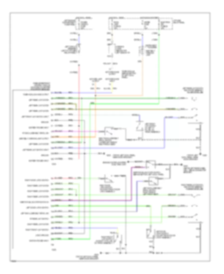
POWER DOOR LOCKS
Keyless Entry Wiring Diagram for Mercury Villager LS 1995
List of elements for Keyless Entry Wiring Diagram for Mercury Villager LS 1995:
- (behind top left side of i/p, taped to harness)
- (left rear corner of cargo area)
- (not used)
- (top left of cowl panel, near door grommet)
- (top right of cowl panel, near door grommet)
- 1/2
- 1/2 input
- 3/4
- 3/4 input
- 5/6
- 5/6 input
- 7/8
- 7/8 input
- 9/0
- 9/0 input
- Battery
- C219
- C221
- Chime control
- Closed
- Diode junction box
- Door ajar input
- Door ajar warning/ rear interior lamp control
- Door lock control
- Door lock/unlock input
- Door open input
- Electron bat fuse 13 10a
- G200
- G200 (top left of cowl panel, near door grommet)
- G200 (top left of cowl panel, near door grommet)
- G203
- G409/g411
- Ground
- Hot at all times
- I/p fuse/relay panel
- Ignition key reminder switch
- Illuminated entry signal input
- Illuminated entry signal output
- Illumination output
- Key in ignition input
- Key-in ign input
- Keyless entry chime (in rear of left front door)
- Keyless entry keypad assembly
- Keyless entry module (behind center of i/p, on center support brace)
- Left door jamb switch
- Left door lock actuator assembly
- Left door lock switch
- Left engine compartment fuse panel
- Liftgate latch switch
- Liftgate lock actuator
- Liftgate open input
- Lock
- Lock input
- Nca
- Open
- Pb05
- Ph01
- Ph02
- Ph03
- Ph05
- Ph06
- Ph07
- Ph08
- Ph09
- Ph11
- Ph16
- Ph18
- Ph20
- Ph31
- Ph32
- Ph34
- Ph35
- Ph38
- Ph41
- Ph42
- Phe1
- Phe2
- Pnk
- Power window fuse 30a
- Right circuit breaker (behind left side of i/p, near cowl panel)
- Right door jamb switch
- Right door lock actuator
- Right door lock switch
- Room lamp fuse 25 15a
- Sliding door ajar input
- Sliding door ajar switch
- Sliding door contact switch
- Sliding door lock actuator
- Sliding door output (delay lock)
- Timer module (behind bottom of left cowl panel)
- Unlock
- Unlock input
Power Door Locks Wiring Diagram for Mercury Villager LS 1995
List of elements for Power Door Locks Wiring Diagram for Mercury Villager LS 1995:
- (behind left side of instrument panel, near cowl panel, left of i/p fuse/relay
- (in front of **
- (in rear of * right "b" pillar)
- (lower rear of right "b" pillar)
- (not used)
- 30a
- Ajar switch
- Battery
- C311
- C329
- Closed
- Door lk cntl
- Door open
- G200 (top of left cowl panel, near door grommet)
- Ground
- Hot at all times
- Input
- L194
- Left door lock switch
- Left door lock actuator assembly
- Left engine compartment fuse panel
- Liftgate lock actuator
- Lock
- Lock input
- Lock/unlock in
- Open
- Output
- Panel)
- Pb01
- Pb02
- Pb04
- Pb05
- Pbo5
- Ph31
- Ph34
- Ph35
- Phe2
- Power window fuse
- Power door lock module (below center of instrument panel, mounted on center instrument panel support bracket)
- Power windows
- Red
- Right door lock switch
- Right circuit breaker
- Right door lock actuator
- Sliding door
- Sliding door
- Sliding door contact switch
- Sliding door lock actuator
- Sliding door)
- Sliding dr input
- System
- Timer module (behind bottom of left cowl panel)
- Un- lock
- Unlock
- Unlock input
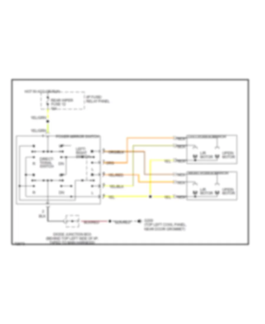
POWER MIRRORS
Power Mirror Wiring Diagram for Mercury Villager LS 1995
List of elements for Power Mirror Wiring Diagram for Mercury Villager LS 1995:
- Diode junction box (behind top left side of i/p, taped to main harness)
- Direct- tional switch
- G200 (top left cowl panel, near door grommet)
- Hot in acc or run
- I/p fuse/ relay panel
- L/r motor
- Left power mirror nca
- Left/ right switch
- Nca
- Power mirror switch
- Rear wiper fuse 12 10a
- Right power mirror nca
- Up/dn motor
POWER SEATS
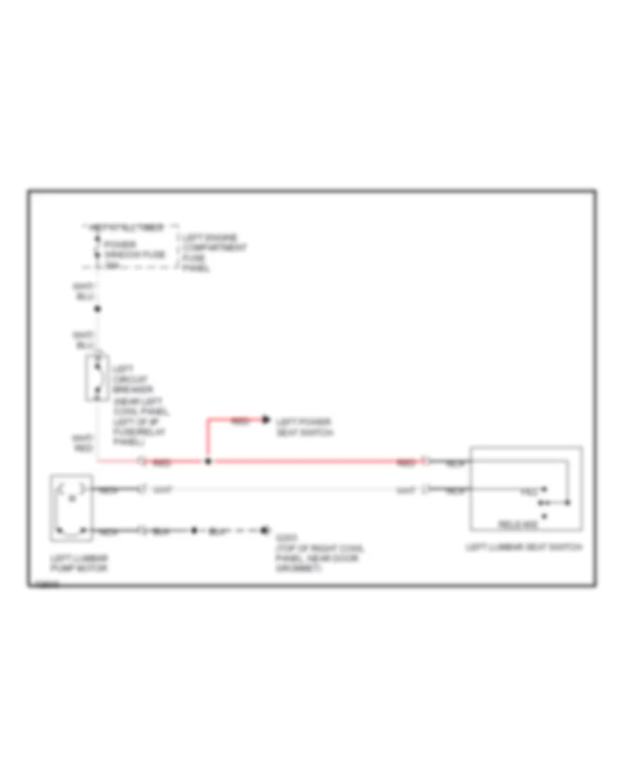
Lumbar Wiring Diagram for Mercury Villager LS 1995
List of elements for Lumbar Wiring Diagram for Mercury Villager LS 1995:
- (near left cowl panel, left of i/p fuse/relay panel)
- Fill
- G203 (top of right cowl panel, near door grommet)
- Hot at all times
- Left circuit breaker
- Left engine compartment fuse panel
- Left lumbar pump motor
- Left lumbar seat switch
- Left power seat switch
- Nca
- Power window fuse 30a
- Red
- Release
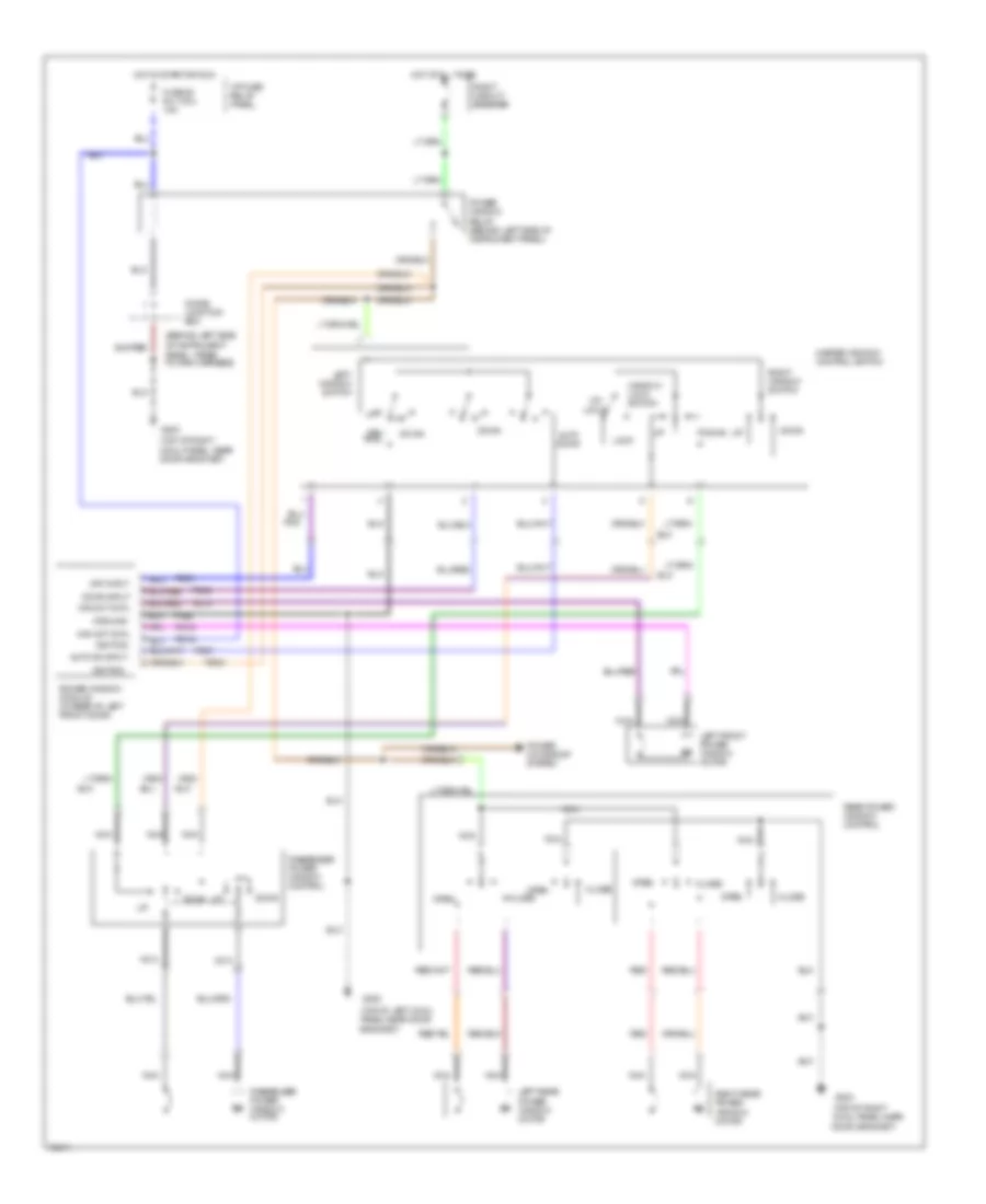
Power Seat Wiring Diagram for Mercury Villager LS 1995
List of elements for Power Seat Wiring Diagram for Mercury Villager LS 1995:
- (near left cowl panel, left of i/p fuse/relay panel)
- G203 (top of right cowl panel, near door grommet)
- Hot at all times
- Left circuit breaker
- Left engine compartment fuse panel
- Left lumbar seat switch
- Left power seat switch
- Left seat motor assembly
- Lifting motor
- Lifting switch
- Nca
- Pnk
- Power window fuse 30a
- Recline switch
- Reclining motor
- Red
- Right power seat switch
- Right seat motor assembly
- Sliding motor
- Sliding switch
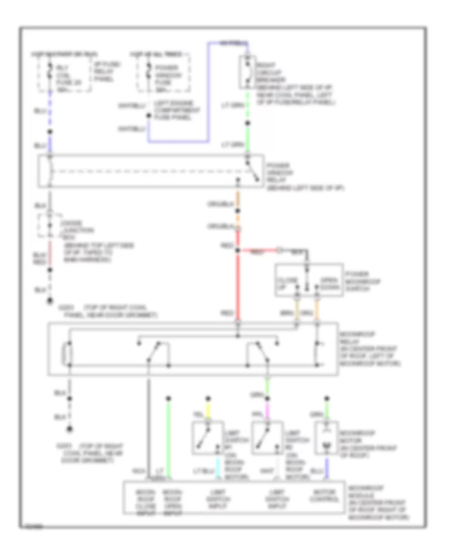
POWER TOP/SUNROOF
Power Top/Sunroof Wiring Diagrams for Mercury Villager LS 1995
List of elements for Power Top/Sunroof Wiring Diagrams for Mercury Villager LS 1995:
- (behind left side of i/p)
- (top of right
- (top of right cowl
- Close up
- Cowl panel, near
- Diode junction box (behind top left side of i/p, taped to main harness)
- Door grommet)
- G203
- Hot at all times
- Hot in start or run
- I/p fuse/ relay panel
- Left engine compartment fuse panel
- Limit switch #1 (on moon- roof motor)
- Limit switch #2 (on moon- roof motor)
- Limit switch input
- Moon- roof close input
- Moon- roof open input
- Moonroof module (in center front of roof, right of moonroof motor)
- Moonroof motor (in center front of roof)
- Moonroof relay (in center front of roof, left of moonroof motor)
- Motor control
- Nca
- Open down
- Panel, near door grommet)
- Power moonroof switch
- Power window fuse 30a
- Power window relay
- Red
- Right circuit breaker (behind left side of i/p, near cowl panel, left of i/p fuse/relay panel)
- Rly coil fuse 20 10a
POWER WINDOWS
Power Window Wiring Diagram for Mercury Villager LS 1995
List of elements for Power Window Wiring Diagram for Mercury Villager LS 1995:
- (behind left side of instrument panel, taped to main harness)
- (top of left cowl panel near door grommet)
- (top of right cowl panel near door grommet)
- (top of right cowl panel, near door grommet)
- Auto dn input
- Auto down
- Close
- Diode junction box
- Down
- Down input
- Fuse 20 rly coil 10a
- G200
- G203
- Ground
- Hot at all times
- Hot in start or run
- I/p fuse/ relay panel
- Ignition
- Left front power window motor
- Left rear power window motor
- Left window switch
- Lock
- Master window control switch
- Nca
- Neu- tral
- Off input
- Open
- Passenger power window control
- Passenger power window motor
- Pd03
- Pd07
- Pd08
- Pd09
- Pd14
- Pd15
- Pd16
- Pde2
- Pnk
- Power moonroof system
- Power window module (in rear of left front door)
- Power window relay (behind left side of instrument panel)
- Rear power window control
- Red
- Right circuit breaker
- Right rear power window motor
- Right window switch
- Un- lock
- Win mot cntl
- Window lock switch
RADIO
Radio Wiring Diagrams, Base Radio for Mercury Villager LS 1995
List of elements for Radio Wiring Diagrams, Base Radio for Mercury Villager LS 1995:
- Antenna ctrl
- Audio fuse 23 10a
- Audio fuse 9 10a
- Batt/memory
- C229
- C233
- C235
- G202 (near left front door grommet)
- Hot at all times
- Hot in acc or run
- I/p fuse/ relay panel (behind dash, left of steering column)
- Illum (+)
- Illum (-)
- Interior lights system
- Left front door speaker
- Left rear speaker
- Lf spkr (+)
- Lf spkr (-)
- Lf01
- Lf04
- Lf91
- Lf94
- Lr sig (+) in
- Lr spkr (+)
- Lr spkr (-)
- Pnk
- Power antenna system
- Pwr
- Pwr gnd
- Ra01
- Ra03
- Ra05
- Ra09
- Ra10
- Ra12
- Ra13
- Ra14
- Ra16
- Ra20
- Ra21
- Ra22
- Ra23
- Ra27
- Ra28
- Ra29
- Ra31
- Radio
- Radio pwr
- Rae2
- Rear radio control
- Remote in
- Remote out
- Rf spkr (+)
- Rf spkr (-)
- Right front door speaker
- Right rear speaker
- Rr sig (+) in
- Rr spkr (+)
- Rr spkr (-)
- S243
- S293
- S305
- S307
- Spkr common
Radio Wiring Diagrams, Premium Radio for Mercury Villager LS 1995
List of elements for Radio Wiring Diagrams, Premium Radio for Mercury Villager LS 1995:
- (1995)
- (not used)
- 12v pwr
- Amp enable
- Amp mute
- Amplifier (above left rear wheelwell)
- Antenna ctrl
- Audio amp fuse 10 20a
- Audio fuse 23 10a
- Audio fuse 9 10a
- Batt/memory
- C2001
- C2002
- C237
- C239
- C241
- C243
- C338
- C340
- C353
- C354
- C430
- Cd player (optional)
- Cd start in
- Cd start out
- Cd-radio shield
- G202 (near left front door grommet)
- G998 (right rear corner of cargo area)
- Gnd
- Hot at all times
- Hot in acc or run
- I/p fuse/ relay panel (behind dash, left of steering column)
- Ign pwr in
- Illum (+)
- Illum (-)
- Interior lights system
- L ch
- Left front door speaker
- Left rear speaker
- Lf spkr (+)
- Lf spkr (-)
- Lf01
- Lf02
- Lf04
- Lf91
- Lf92
- Lf94
- Lr sig (+) in
- Lr sig (-) in
- Lr spkr (+)
- Lr spkr (-)
- Nca
- Pnk
- Power antenna system
- Pwr
- Pwr gnd
- R ch
- Ra01
- Ra03
- Ra05
- Radio
- Radio amplifier shield
- Radio on out
- Radio pwr
- Rb08
- Rb09
- Rb10
- Rb11
- Rb12
- Rb13
- Rb14
- Rb15
- Rb16
- Rb26
- Rb27
- Rb28
- Rb29
- Rb30
- Rb31
- Rb32
- Rb33
- Rb34
- Rb35
- Rb36
- Rb37
- Rb38
- Rb40
- Rb41
- Rb42
- Rb49
- Rb50
- Rb51
- Rb52
- Rb53
- Rb54
- Rb55
- Rb93
- Rbe1
- Rbe2
- Rbe3
- Rear control amp shield
- Rear radio control
- Remote in
- Remote out
- Rf spkr (+)
- Rf spkr (-)
- Right front door speaker
- Right rear speaker
- Rr sig (+) in
- Rr sig (-) in
- Rr spkr (+)
- Rr spkr (-)
- S2014
- S243
- S245
- S293
- S305
- S315
- S321
- Shield
- Sig return
- Subwfr (+)
- Subwfr (-)
- Subwfr mute
- Subwfr out
- Subwoofer amplifier (optional) (above right rear wheelwell behind subwoofer speaker)
- Subwoofer shield
- Subwoofer speaker (optional)
- Subwrf (+)
- Tan
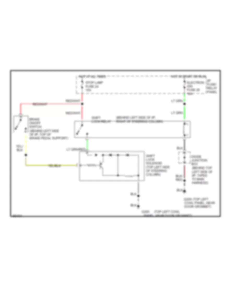
SHIFT INTERLOCKS
Shift Interlock Wiring Diagram for Mercury Villager LS 1995
List of elements for Shift Interlock Wiring Diagram for Mercury Villager LS 1995:
- (behind left side of i/p, right of steering column)
- (top left
- (top left cowl panel, near door grommet)
- Brake on/off switch (behind left side of i/p, top of brake pedal support)
- Cowl panel, near door grommet)
- Diode junction box (behind top left side of i/p, taped to main harness)
- Electron ign fuse 26 10a
- G200
- Hot at all times
- Hot in start or run
- I/p fuse/ relay panel
- Shift lock relay
- Shift lock solenoid (top left side of steering column)
- Stop lamp fuse 24 15a
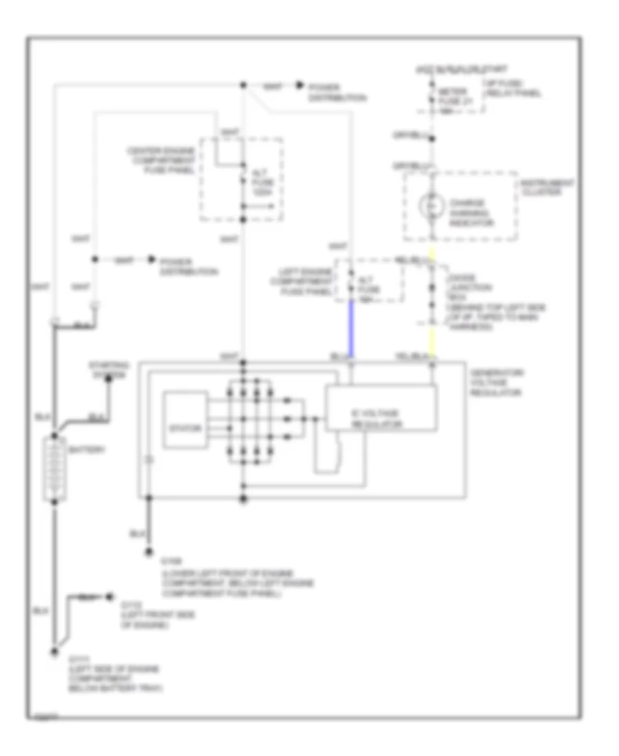
STARTING/CHARGING
Charging Wiring Diagram for Mercury Villager LS 1995
List of elements for Charging Wiring Diagram for Mercury Villager LS 1995:
- (lower left front of engine compartment, below left engine compartment fuse panel)
- Alt fuse 10a
- Alt fuse 120a
- Battery
- Center engine compartment fuse panel
- Charge warning indicator
- Diode junction box (behind top left side of i/p, taped to main harness)
- G108
- G111 (left side of engine compartment, below battery tray)
- G112 (left front side of engine)
- Generator/ voltage regulator
- Hot in run or start
- I/p fuse/ relay panel
- Ic voltage regulator
- Instrument cluster
- Left engine compartment fuse panel
- Meter fuse 21 10a
- Power distribution
- Starting system
- Stator
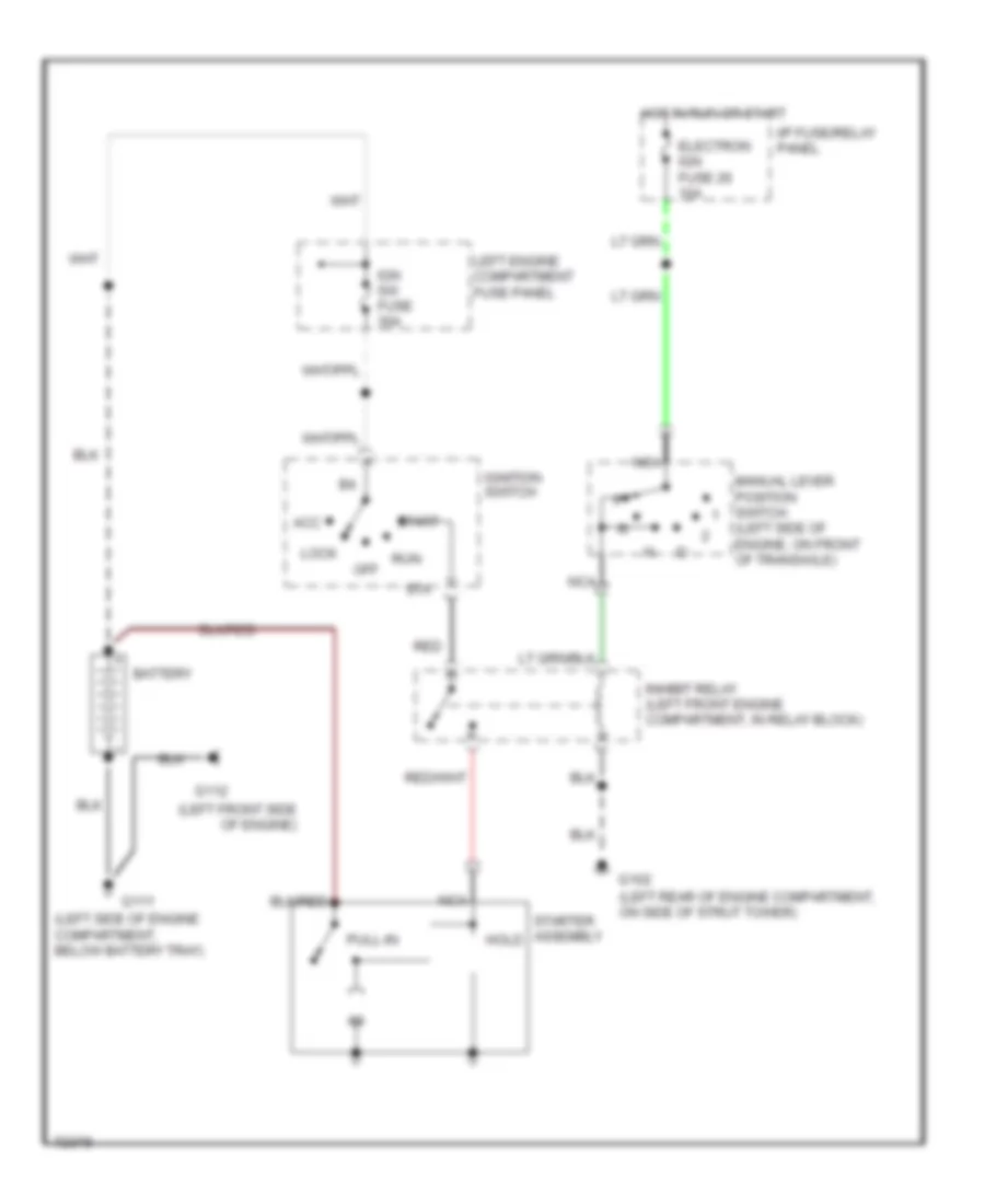
Starting Wiring Diagram for Mercury Villager LS 1995
List of elements for Starting Wiring Diagram for Mercury Villager LS 1995:
- (left front side of engine)
- (left rear of engine compartment, on side of strut tower)
- (left side of engine compartment, below battery tray)
- (left side of engine, on front of transaxle)
- Acc
- Battery
- Electron ign fuse 26 10a
- G102
- G111
- G112
- Hold
- Hot in run or start
- I/p fuse/relay panel
- Ign sw fuse 30a
- Ignition switch
- Inhibit relay (left front engine compartment, in relay block)
- Left engine compartment fuse panel
- Lock
- Manual lever position switch
- Nca
- Off
- Pull-in
- Red
- Run
- Sta
- Start
- Starter assembly
SUPPLEMENTAL RESTRAINTS
Supplemental Restraint Wiring Diagram for Mercury Villager LS 1995
List of elements for Supplemental Restraint Wiring Diagram for Mercury Villager LS 1995:
- "air bag" indicator
- Air bag diagnostic monitor (behind left side of i/p)
- Air bag fuse 14 10a
- C2003
- C2004
- C2013
- C2014
- C268
- Clockspring assembly
- Data link connector (dlc) (behind left side of i/p, on bottom of i/p fuse/relay panel)
- Dlc interface
- Door open input
- Driver's air bag
- Driver's air bag inflation control
- Engine controls and transmissions systems
- Front crash zone sensor (center front of vehicle)
- Front crash zone sensor input
- G200 (top of left cowl panel, near door grommet)
- Ground
- Hot at all times
- Hot in run
- Hot in run or start
- I/p fuse/ relay panel
- Indicator
- Instrument cluster
- Left door jamb switch
- Meter fuse 21 10a
- Nca
- Power
- Power input
- Ps01
- Ps02
- Ps03
- Ps10
- Ps11
- Ps14
- Ps15
- Ps16
- Ps17
- Ps18
- Ps19
- Ps24
- Ps25
- Ps26
- Ps27
- Pse1
- Room lamp fuse 25 15a
- Safing sens input
- Safing sensor
- Tunnel and safing sensor (below center of i/p)
- Tunnel sens input
- Tunnel sensor
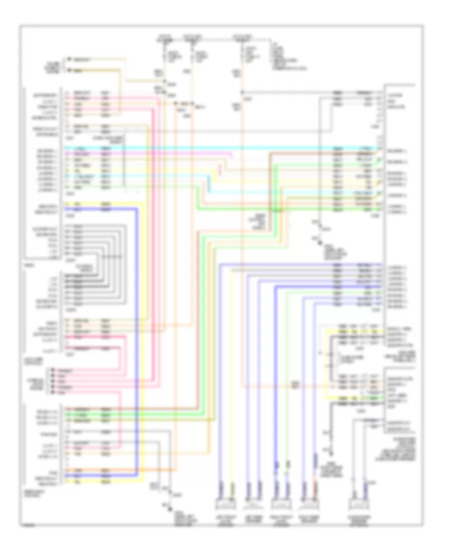
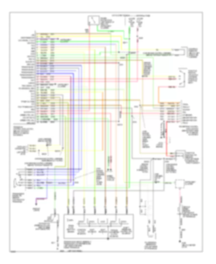
TRANSMISSION
Transmission Wiring Diagram for Mercury Villager LS 1995
List of elements for Transmission Wiring Diagram for Mercury Villager LS 1995:
- #2 (left side
- (behind top right side of i/p, behind glove box)
- (engine control harness, center rear of engine compt) s166
- (engine control harness, in break out to tcm
- (left kick panel)
- (main engine control harness, behind top right side of i/p)
- (main engine control harness, near break out to pcm)
- (main engine control harness, near break out to ect sensor)
- (main engine control harness, near break out to egr valve)
- (main engine control harness, near break out to pcm)
- (main harness, behind center of i/p) s2024
- (main harness, top of i/p) s2049
- (top right of steering column part of gear shift selector)
- Av20
- Av21
- Av33
- Av37
- Av44
- Backup lights
- Ccs
- Coasting clutch solenoid
- Data link connector
- Dlc
- Drop resistor
- Dropping resistor (below left side of air cleaner)
- E-at switch
- Ej08
- Ej17
- Elect pressure control (pc) solenoid
- Fuse elec bat 10a
- Fuse elec ign 10a
- G134 (top of engine)
- G200
- G206 (below center of i/p)
- Ground
- Hot at all times
- Hot in start or run
- Iat sensor
- Idle sw in
- Ignition
- Instrument cluster
- Itps in
- Kapwr
- Lps
- Nca
- O/d cancel lt out
- O/d off sw in
- O/d off switch
- Of i/p)
- Pcm in
- Pcm tp sens input
- Pnk
- Power e-at switchd (left side of i/p right of instrument cluster)
- Powertrain control module (pcm) (behind right side of i/p, behind glove box)
- Psg
- Pulse signal gen
- Pulse signal generator (top left rear of transaxle)
- Red
- S153
- S159
- S160
- S161
- S162
- S2011
- S2015
- S2019
- S2020
- S2022
- S2029
- S2030
- S2031
- S211
- S286
- S290
- Sensor
- Sensor return
- Shift solenoid
- Speed control module
- Speed ctrl mdl
- Ssa
- Ssb
- Tach signal in
- Tcc
- Tcm/pnp
- Throttle position (tp) sensor (top left rear of engine, on throttle body)
- Throttle position (tp) switch (top rear of eng, on throttle body)
- Torque converter clutch solenoid
- Tot
- Tp ref voltage
- Tps
- Tps in
- Tps out
- Trans fluid temp (tft)
- Trans range 1
- Trans range 2
- Trans range d
- Trans range p/n
- Trans range r
- Transaxle control module (tcm)
- Transaxle solenoid assembly/ transaxle fluid temperature (left side of engine, inside transaxle)
- Transmission range (tr) sensor (top front of transaxle)
- Vehicle speed sensor (left side of engine, on rear of transaxle)
- Vss in
- Wot
- Ze15
- Ze48
- Zy01
- Zy02
- Zy03
- Zy04
- Zy05
- Zy06
- Zy07
- Zy08
- Zy09
- Zy13
- Zy14
- Zy16
- Zy17
- Zy18
- Zy19
- Zy20
- Zy21
- Zy23
- Zy24
- Zy25
- Zy27
- Zy28
- Zy29
- Zy30
- Zy31
- Zy33
- Zy34
- Zy35
- Zy36
- Zy39
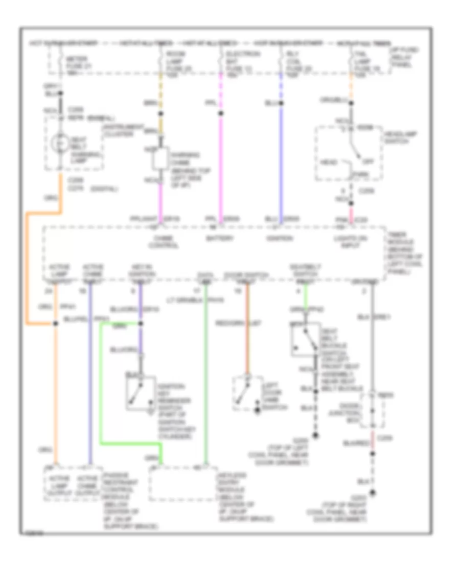
WARNING SYSTEMS
Warning System Wiring Diagrams for Mercury Villager LS 1995
List of elements for Warning System Wiring Diagrams for Mercury Villager LS 1995:
- (behind top left side of i/p)
- (digital)
- Active chime input
- Active chime output
- Active lamp output
- Battery
- C256
- C258
- C268 c276
- Chime control
- Data line
- Diode junction box
- Door switch input
- Electron bat fuse 13 10a
- G200 (top of left cowl panel, near door grommet)
- G203 (top of right cowl panel, near door grommet)
- Ground
- Head
- Headlamp switch
- Hot at all times
- Hot in run or start
- I/p fuse/ relay panel
- Ignition
- Ignition key reminder switch (part of ignition switch key cylinder)
- Instrument cluster
- Key in ignition input
- Keyless entry module (below center of i/p, on i/p support brace)
- Left door jamb switch
- Lights on input
- Meter fuse 21 10a
- Nca
- Off
- Park
- Passive restraint control module (below center of i/p, on i/p support brace)
- Pnk ic20
- Rly coil fuse 20 10a
- Room lamp fuse 25 15a
- Seat belt buckle switch (on left front seat assembly, near seat belt buckle
- Seat belt warning lamp
- Seatbelt switch input
- Tail lamp fuse 19 15a
- Timer module (behind bottom of left cowl panel)
- Warning chime
WIPER/WASHER
Front Wiper/Washer Wiring Diagram for Mercury Villager LS 1995
List of elements for Front Wiper/Washer Wiring Diagram for Mercury Villager LS 1995:
- (center of left fender apron)
- (center of right fender apron) g103
- 100k ohms
- 3.3k ohms
- 4.08k
- 7.25k
- C134
- C136
- Combination switch
- Front wiper fuse 6 20a
- Front washer pump motor (in washer fluid reservoir)
- Front wiper motor assembly
- G102
- Ground
- Hi speed input
- Hot in accy or run
- I/p fuse/ relay panel
- Ignition
- Int max
- Int min
- Internal adjust input
- Interval wiper/washer switch
- Nca
- Off
- Off 36.27k
- Ohms
- Park
- Park switch
- Red
- Run
- Run/ park input
- Wa03
- Wa06 red
- Wa07
- Wa08
- Wa09
- Wae1
- Wae3
- Washer motor control
- Washer on input
- Washer switch
- Wiper motor
- Wiper motor control
- Wiper/washer amplifier assembly (left side of engine compaertment, on front of strut tower)
Rear Wiper/Washer Wiring Diagram, with Moveable Liftgate Glass for Mercury Villager LS 1995
List of elements for Rear Wiper/Washer Wiring Diagram, with Moveable Liftgate Glass for Mercury Villager LS 1995:
- (top left cowl panel, near door grommet)
- G200
- Glass closed
- Hot in accy or run
- I/p fuse/ relay panel
- Interior lights system
- Nca
- Opening liftgate glass switch (right center of liftgate, below glass)
- Park
- Pnk
- Rear washer motor (in washer fluid reservoir)
- Rear wiper fuse 12 10a
- Rear wiper motor assembly
- Rear wiper relay (above left rear wheel well)
- Rear wiper/ washer diode junction box (above left rear wheel well)
- Rear wiper/ washer switch
- Run
- Washer switch
- Wiper amp
- Wiper switch
Rear Wiper/Washer Wiring Diagram, without Moveable Liftgate Glass for Mercury Villager LS 1995
List of elements for Rear Wiper/Washer Wiring Diagram, without Moveable Liftgate Glass for Mercury Villager LS 1995:
- (in washer fluid reservoir) rear washer motor
- (left rear
- (top left cowl panel, near door grommet)
- G200
- G409 cargo area)
- Ground
- Hot in accy or run
- I/p fuse/ relay panel
- Ignition
- Interior lights system
- Liftgate washer switch
- Liftgate wiper switch
- Motor control
- Nca
- Park
- Pnk
- Rear wiper fuse 12 10a
- Rear wiper motor assembly
- Rear wiper/ washer amplifier (above left rear wheel well)
- Rear wiper/washer switch
- Run
- Run/ park input
- Washer on input
- Wb08
- Wiper on input