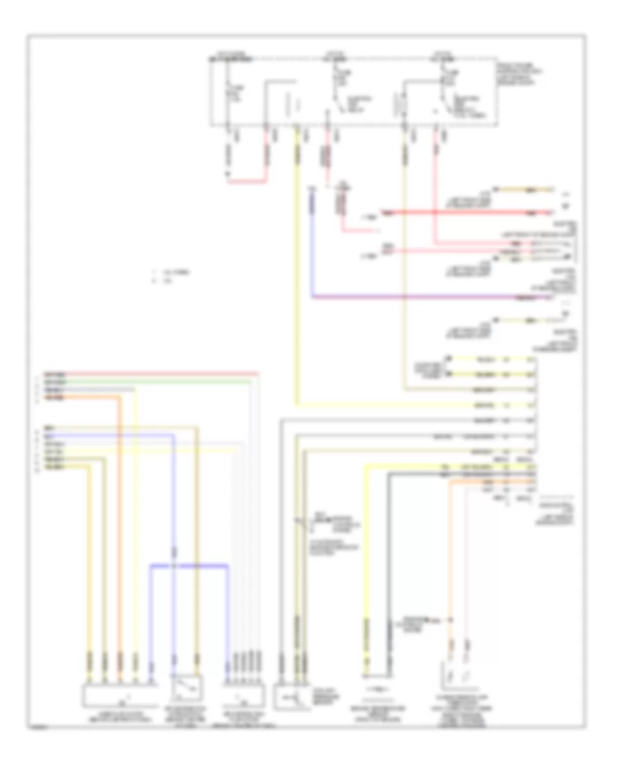
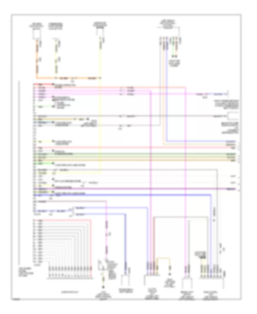
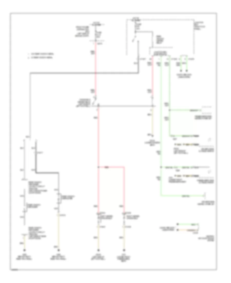
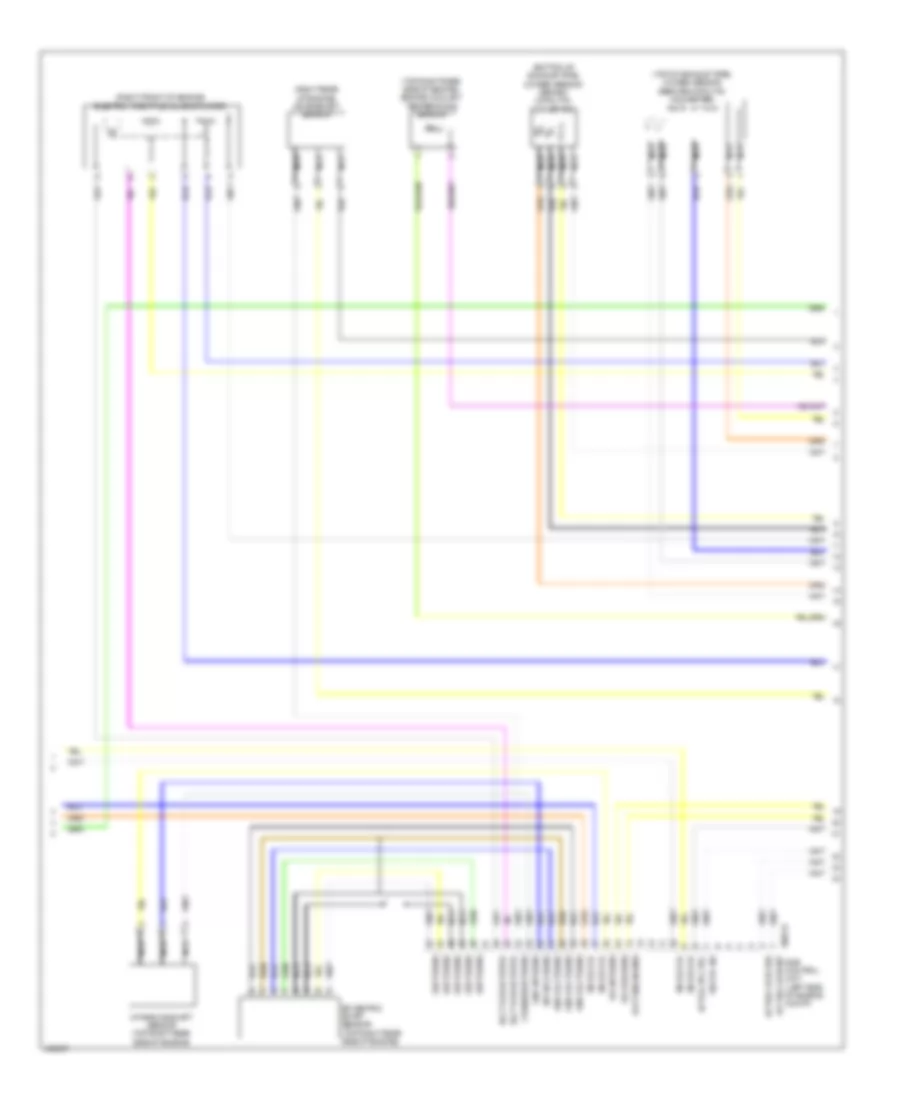
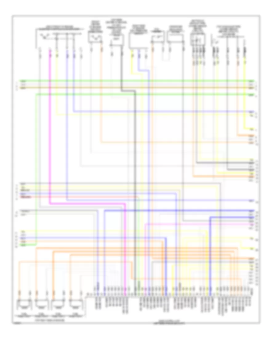
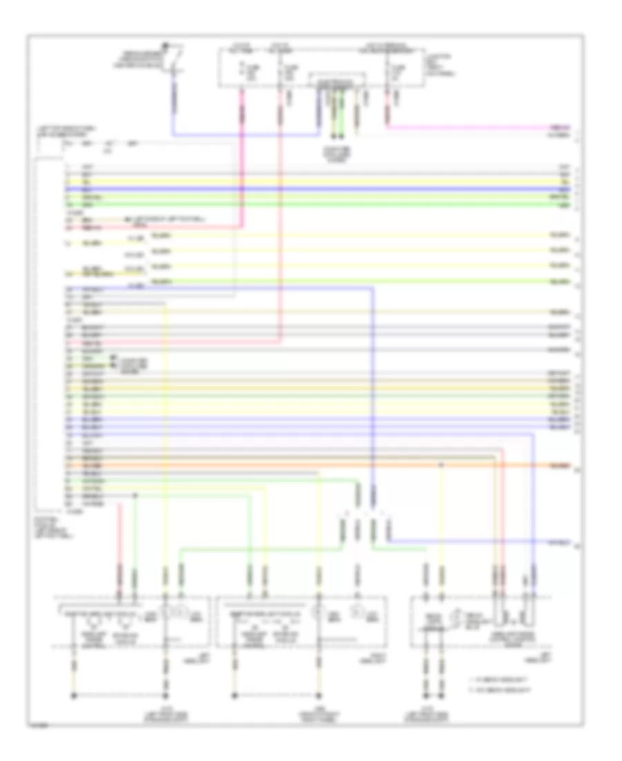
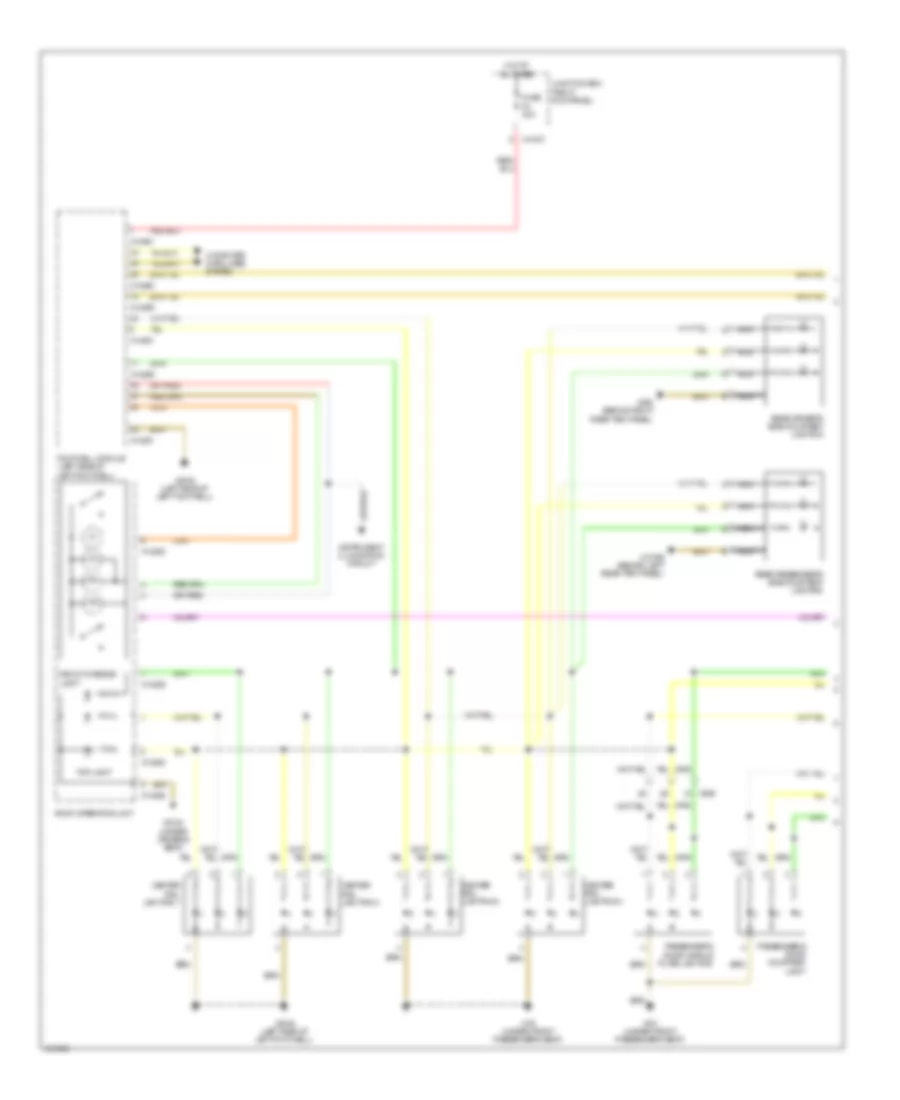
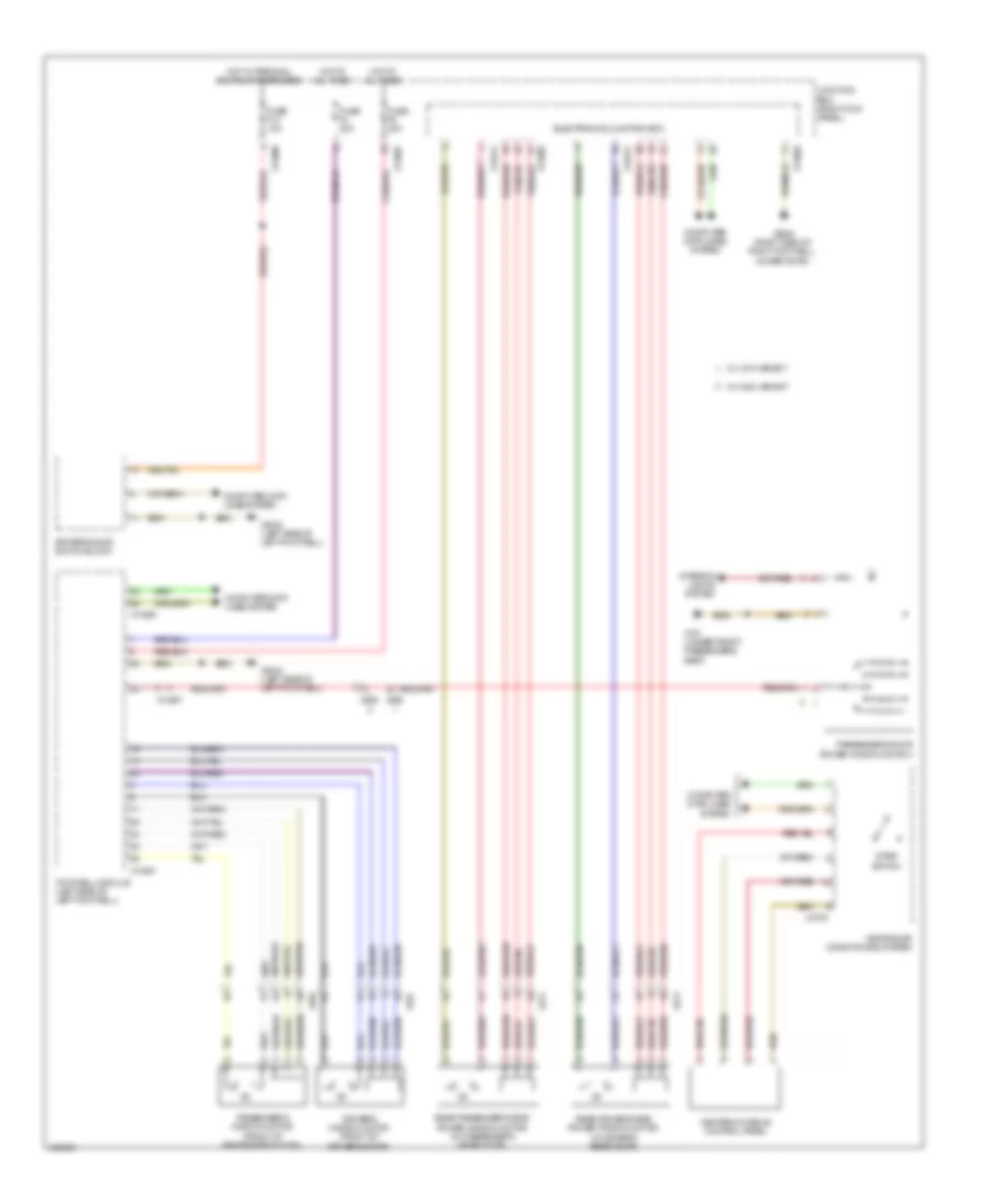
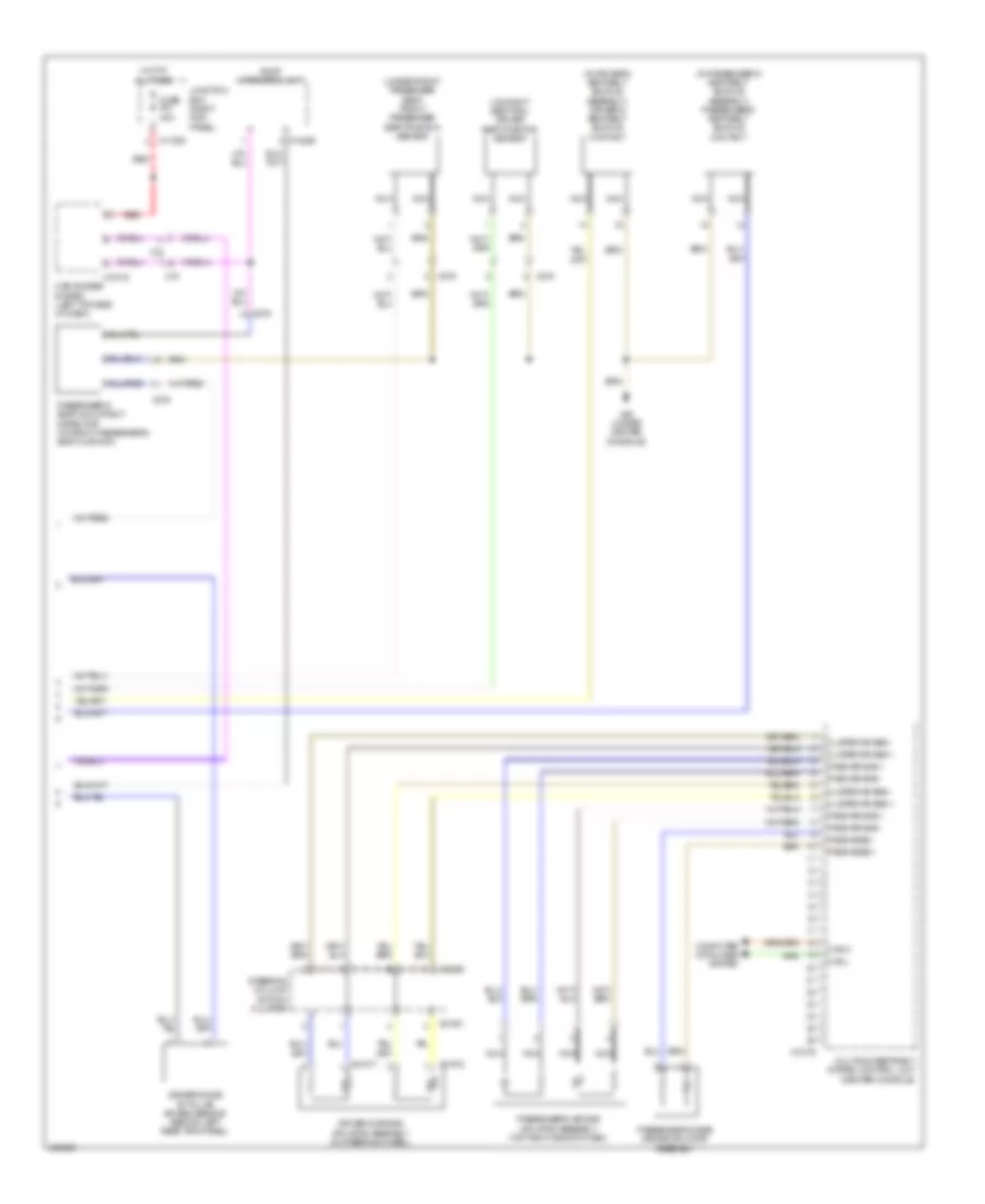
AIR CONDITIONING
Automatic A/C Wiring Diagram (1 of 2) for MINI Cooper Paceman S ALL4 2014

List of elements for Automatic A/C Wiring Diagram (1 of 2) for MINI Cooper Paceman S ALL4 2014:
- A/c compressor relay
- Anti-theft system
- Blower motor (behind center of dash)
- Blower output stage (behind center of dash)
- Center console control panel
- Compressor clutch (lower right front of engine)
- Computer data lines system
- Electronics junction box
- Evaporator temperature sensor (behind center of dash)
- Fresh air/ recirculation flap motor (behind center of dash)
- Fuse f20 10a
- Fuse f24 10a
- Fuse f48 30a
- Heat exchanger sensor (behind center of dash)
- Heater blower relay
- Heating/air conditioning system
- Hot at all times
- Hot w/ terminal 30g relay energized
- Interior lights system
- Junction box (right kick panel)
- Red
- Solar sensor (behind center of dash)
- X11007
- X11009
- X165 (front of right front wheel)
- X1879
- X2042 (left side of left footwell)
- X6056
- X610
- X9331
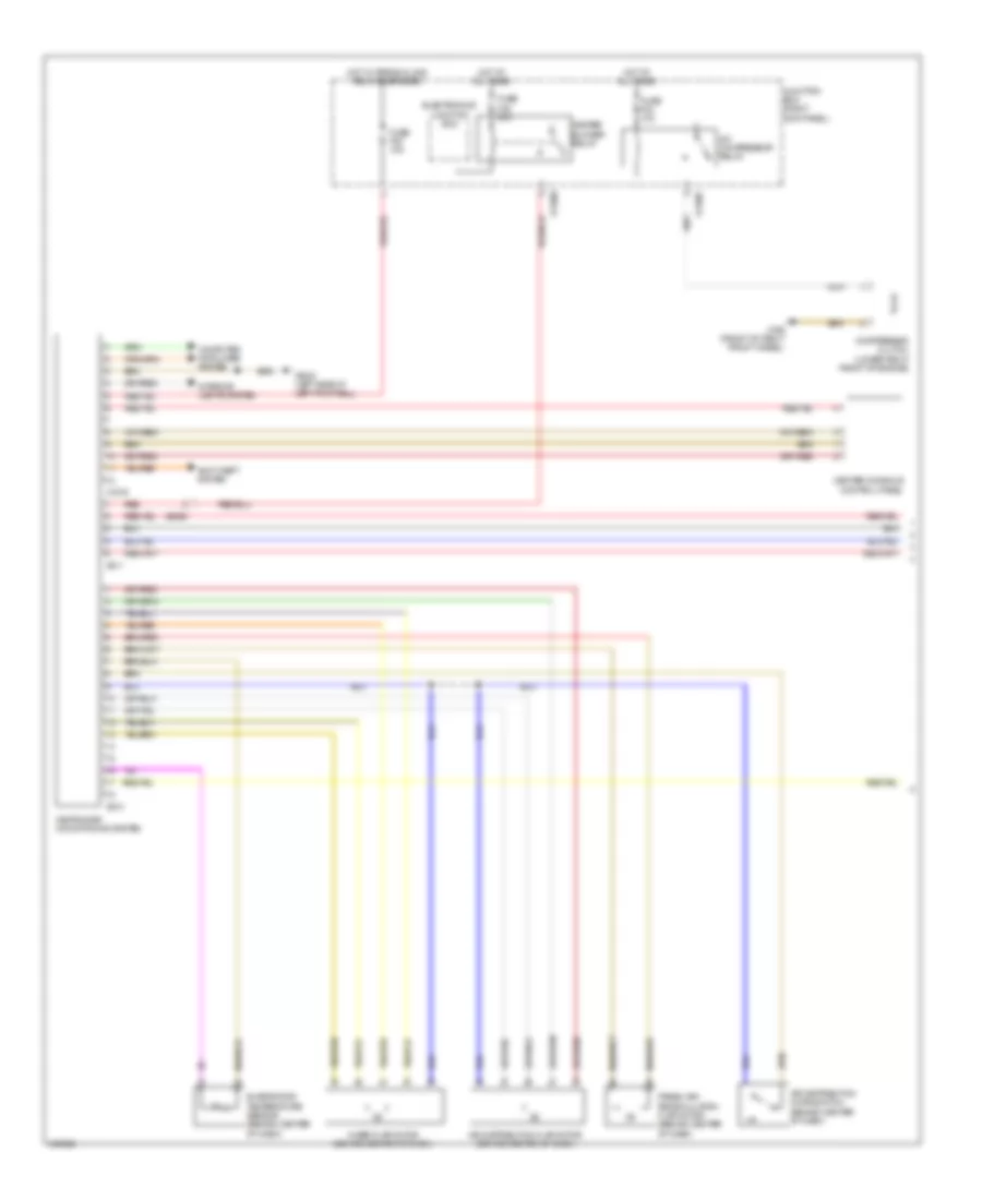
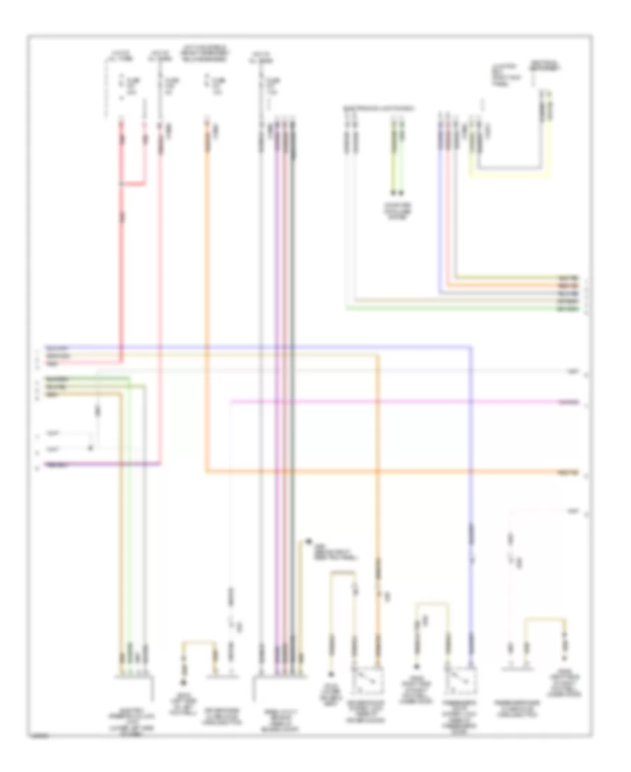
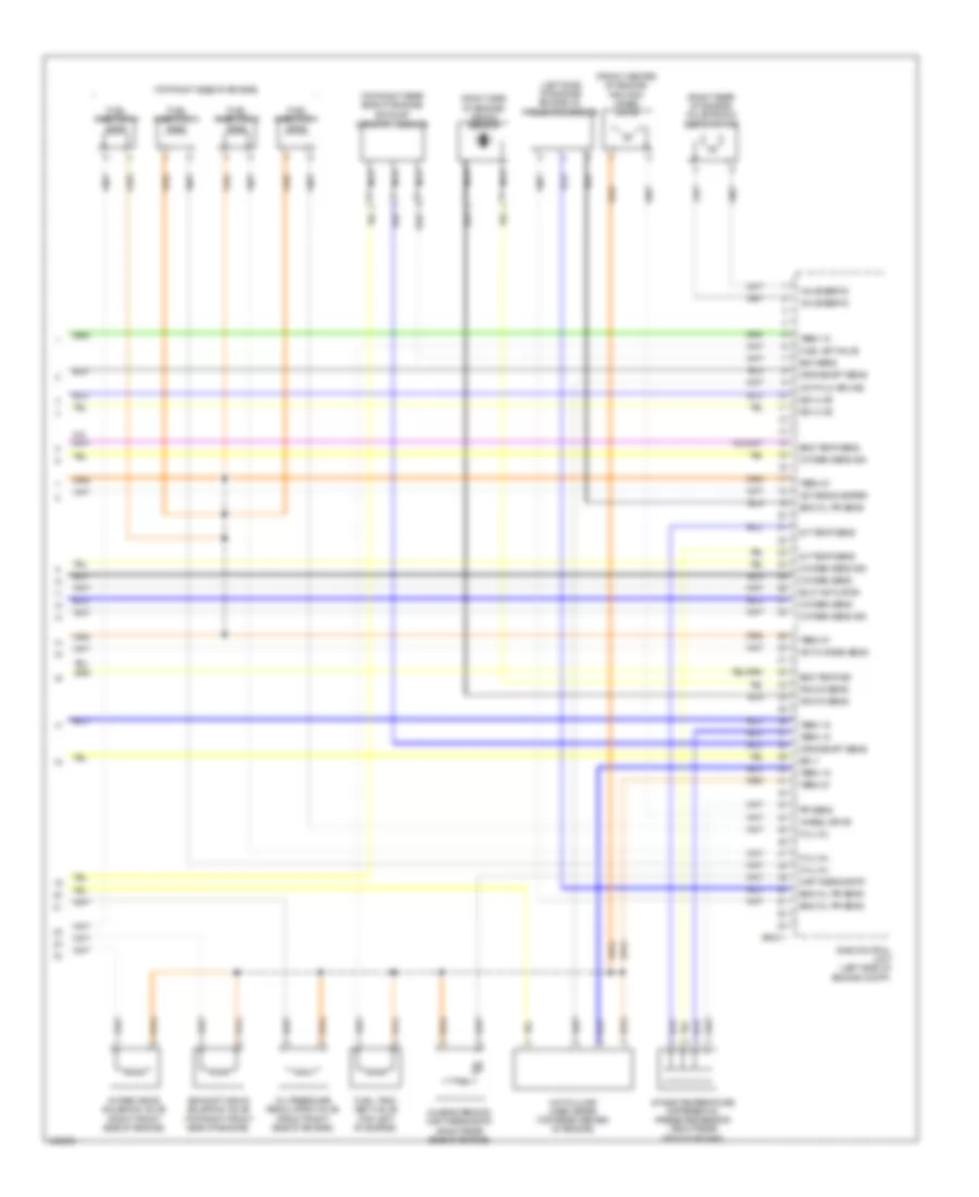
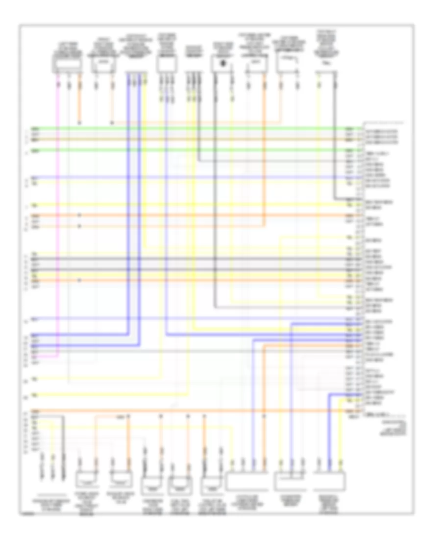
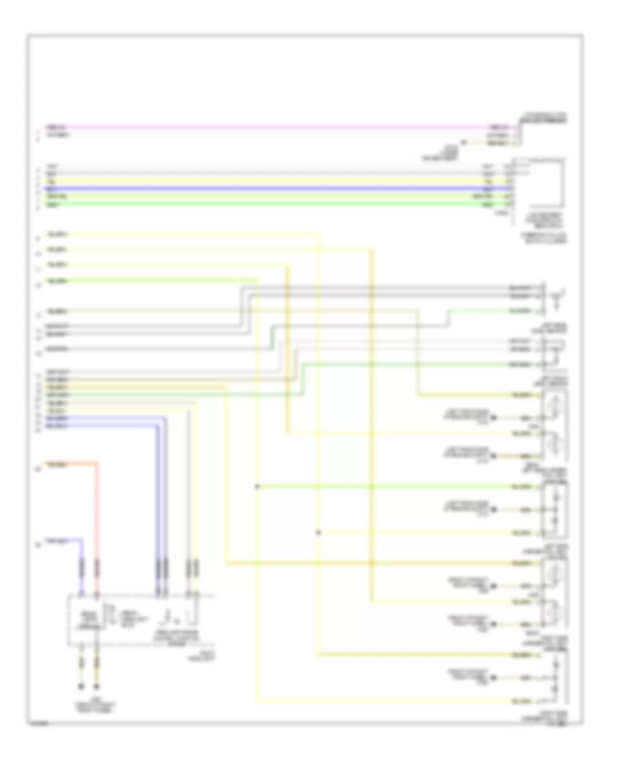
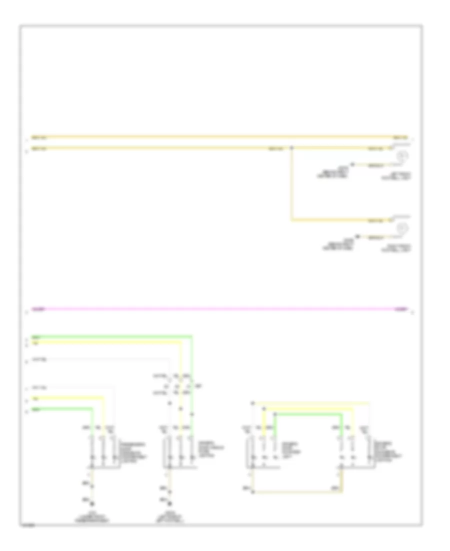
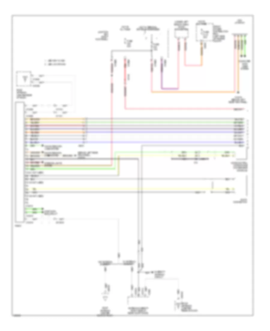
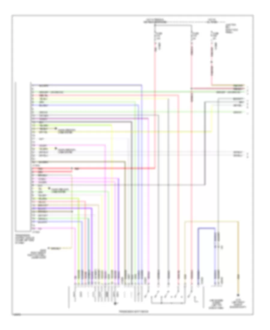
Automatic A/C Wiring Diagram (2 of 2) for MINI Cooper Paceman S ALL4 2014
List of elements for Automatic A/C Wiring Diagram (2 of 2) for MINI Cooper Paceman S ALL4 2014:
- 1-tier
- 1.6l
- 1.6l turbo
- 2-tier
- Air distribution flap motor (behind center of dash)
- Air distribution microswitch (behind center of dash)
- Characteristic map thermostat (non turbo: right rear side of engine) (turbo: top rear center of engine)
- Computer data lines system
- Coolant pressure sensor
- Dme control unit (left side of engine compt)
- Electric fan (left front of engine compt)
- Electric fan relay
- Electric fan relay 2 (1.6l turbo)
- Engine controls system
- Engine temperature sensor (front of engine)
- Front power distribution box (left side of engine compt)
- Fuse f05 7.5a
- Fuse f08 40a
- Fuse fl9 50a
- Hot at all times
- Hot w/ dme relay energized
- Mixer flap motor (behind center of dash)
- Red
- W/ automatic engine start/stop function
- X175 (left front side of engine compt)
- X4007
- X4010
- X4013
- X4014
- X60004
- X60211
- X60231
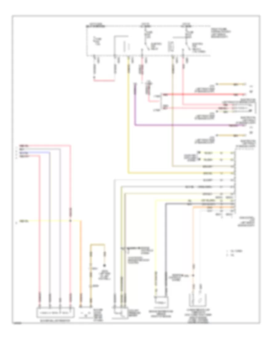
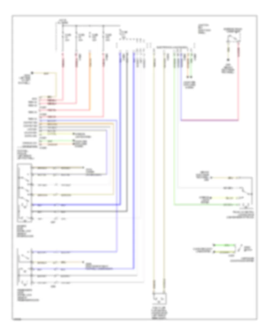
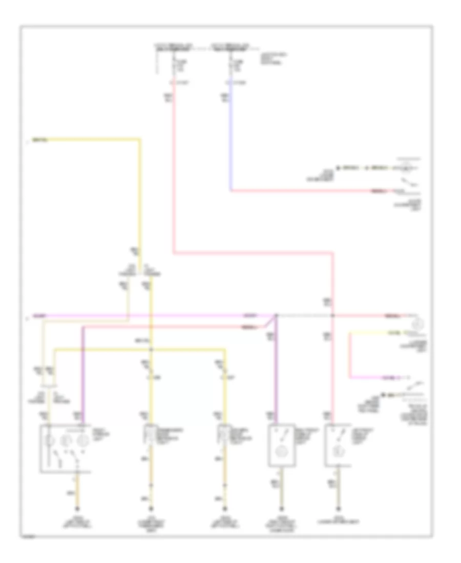
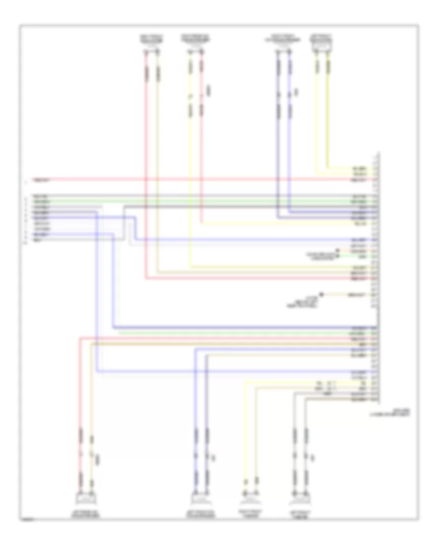
Manual A/C Wiring Diagram (1 of 2) for MINI Cooper Paceman S ALL4 2014
List of elements for Manual A/C Wiring Diagram (1 of 2) for MINI Cooper Paceman S ALL4 2014:
- A/c compressor relay
- Air distribution flap motor (behind center of dash)
- Air distribution microswitch (behind center of dash)
- Anti-theft system
- Center console control panel
- Compressor clutch (lower right front of engine)
- Computer data lines system
- Electronics junction box
- Evaporator temperature sensor (behind center of dash)
- Fresh air/ recirculation flap motor (behind center of dash)
- Fuse f20 10a
- Fuse f24 10a
- Fuse f48 30a
- Heater blower relay
- Heating/air conditioning system
- Hot at all times
- Hot w/ terminal 30g relay energized
- Interior lights system
- Junction box (right kick panel)
- Mixer flap motor (behind center of dash)
- Red
- X11007
- X11009
- X165 (front of right front wheel)
- X1879
- X2042 (left side of left footwell)
- X6056
- X610
- X611
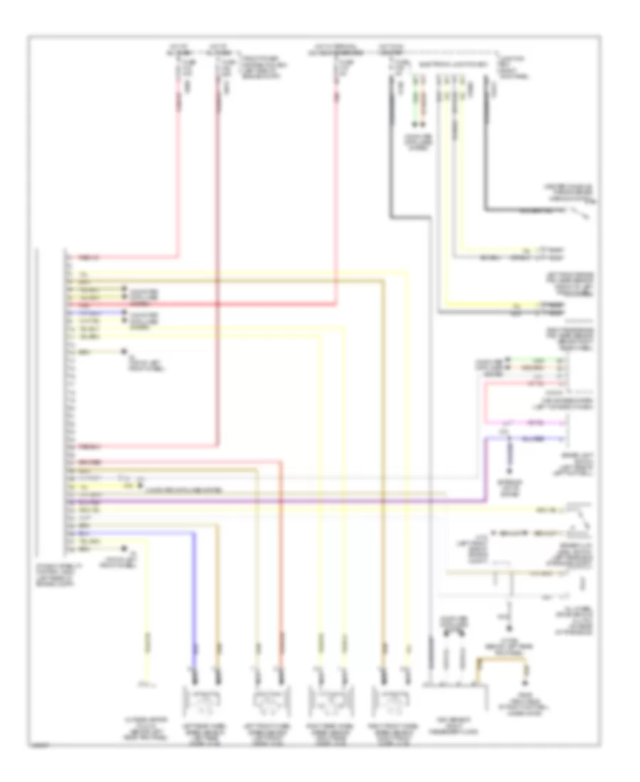
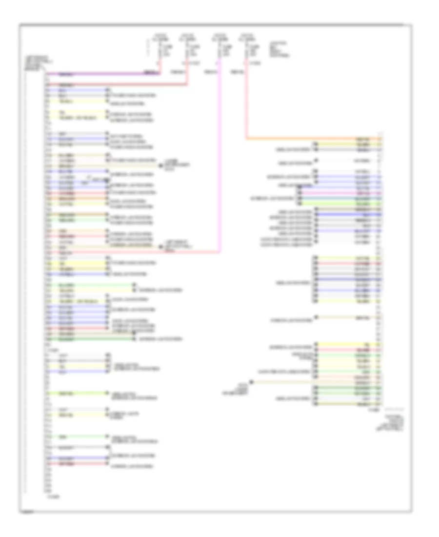
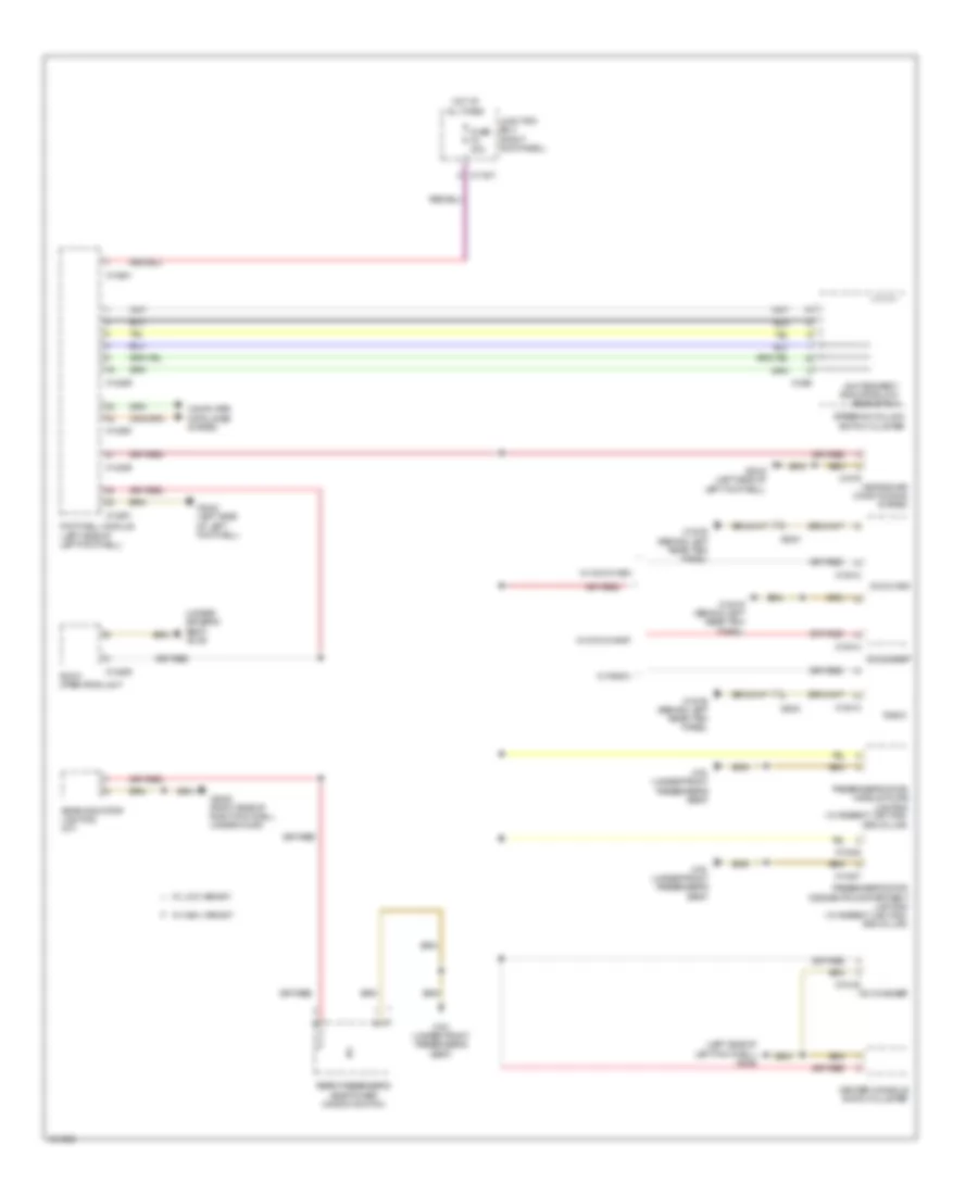
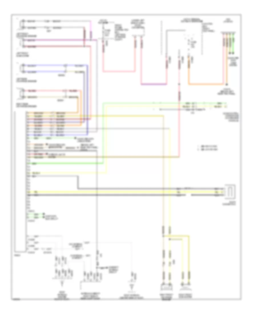
Manual A/C Wiring Diagram (2 of 2) for MINI Cooper Paceman S ALL4 2014
List of elements for Manual A/C Wiring Diagram (2 of 2) for MINI Cooper Paceman S ALL4 2014:
- 1-tier
- 1.6l
- 1.6l turbo
- 2-tier
- Blower ballast resistor
- Blower motor (behind center of dash)
- Characteristic map thermostat (non turbo: right rear side of engine) (turbo: top rear center of engine)
- Computer data lines system
- Coolant pressure sensor
- Dme control unit (left side of engine compt)
- Electric fan (left front of engine compt)
- Electric fan relay
- Electric fan relay 2 (1.6l turbo)
- Engine controls system
- Engine temperature sensor (front of engine)
- Front power distribution box (left side of engine compt)
- Fuse f05 7.5a
- Fuse f08 40a
- Fuse fl9 50a
- Hot at all times
- Hot w/ dme relay energized
- Red
- W/ automatic engine start stop function
- X175 (left front side of engine compt)
- X2042 (left side of left footwell)
- X4007
- X4010
- X4013
- X4014
- X60004
- X60211
- X60231
- X6056
- X9331
ANTI-LOCK BRAKES
Anti-lock Brakes Wiring Diagram for MINI Cooper Paceman S ALL4 2014
List of elements for Anti-lock Brakes Wiring Diagram for MINI Cooper Paceman S ALL4 2014:
- (center console) parking brake warning switch
- All-wheel drive vehicle clutch (on rear of transaxle)
- Brake fluid level switch (left rear side of engine compt)
- Brake light switch (left side of left footwell)
- Car access system (left top side of dash)
- Computer data lines system
- Dsc sensor (right passenger floor)
- Dynamic stability control (dsc) (left rear of engine compt)
- Electronic junction box
- Exterior lights system
- Front power distribution box (left side of engine compt)
- Fuse f06 25a
- Fuse f18 5a
- Fuse f35 5a
- Fuse fl6 40a
- Hot at all times
- Hot in on or start
- Hot w/ terminal 30g relay energized
- Junction box (right kick panel)
- Left front brake pad wear sensor (front of left front wheel)
- Left front wheel speed sensor (left front wheel hub)
- Left rear wheel speed sensor (left rear wheel hub)
- Nca
- Outside mirror fold-in (behind left rear trim panel)
- Red
- Right front wheel speed sensor (right front wheel hub)
- Right rear brake pad wear sensor (behind right rear wheel)
- Right rear wheel speed sensor (right rear wheel hub)
- X10318
- X11002
- X1108
- X13795 (behind left rear trim panel)
- X14272
- X15
- X175 (left front side of engine compt)
- X2846 (right side of right footwell, under door)
- X4 (top of left front wheel)
- X4010
- X4013
ANTI-THEFT
Access/Start Wiring Diagram (1 of 3) for MINI Cooper Paceman S ALL4 2014
List of elements for Access/Start Wiring Diagram (1 of 3) for MINI Cooper Paceman S ALL4 2014:
- (left side of left footwell) footwell module
- A/t
- Anti-lock brakes system
- Brake light switch (left side of left footwell)
- Car access system (left top side of dash)
- Clutch module (m/t) (under left side of dash)
- Computer data lines system
- Dme control unit (left side of engine compt)
- Driver's door switch block
- Front passenger seat occupancy detector (in front passenger's seat cushion)
- Heating/air conditioning system
- Hood contact switch (left rear side of engine compt)
- M/t
- Mirrors system
- Passenger's door center lock button
- Power distribution system
- Red
- Selector lever position switch (a/t) (at base of gear selector)
- Start stop unit
- Starting/ charging system
- Transmission shift device
- X10318
- X11632
- X13269
- X14027
- X14260
- X14261
- X15
- X175 (left front side of engine compt)
- X1879
- X2042 (left side of left footwell)
- X256
- X257
- X279
- X60004
Access/Start Wiring Diagram (2 of 3) for MINI Cooper Paceman S ALL4 2014
List of elements for Access/Start Wiring Diagram (2 of 3) for MINI Cooper Paceman S ALL4 2014:
- Additional instrument
- Computer data lines system
- Driver's door system lock (rear of driver's door)
- Driver's side outer door handle button
- Electric steering column lock (under left side of dash)
- Electronics junction box
- Fuse f21 10a
- Fuse f27 7.5a
- Fuse f36 5a
- Fuse f51 40a
- Hot at all times
- Hot w/ bi-stable variant dependent relay energized
- Junction box (right kick panel)
- Passenger's door system lock (rear of passenger's door)
- Passenger's side outer door handle button
- Red
- Siren w/ tilt sensor (rear of engine compt)
- X11001
- X11002
- X11006
- X11008
- X14272
- X2042 (left side of left footwell)
- X2184 (under driver's seat)
- X256
- X257
- X2846 (right side of right footwell, under door)
- X490 (behind right rear trim panel)
Access/Start Wiring Diagram (3 of 3) for MINI Cooper Paceman S ALL4 2014
List of elements for Access/Start Wiring Diagram (3 of 3) for MINI Cooper Paceman S ALL4 2014:
- (center rear of trunk) trunk lid central locking drive
- (in overhead console) interior movement detector
- Comfort access control module (behind right rear trim panel)
- Computer data lines system
- Computer data lines system x490 (behind right rear trim panel)
- Driver's side section interior aerial
- Electrochromic interior rearview mirror
- Front center console interior antenna (center console)
- Interior lights system
- Passenger's side section interior aerial
- Rear fender aerial
- Rear interior
- X15
- X2184 (under driver's seat)
- X256
- X257
- X490 (behind right rear trim panel)
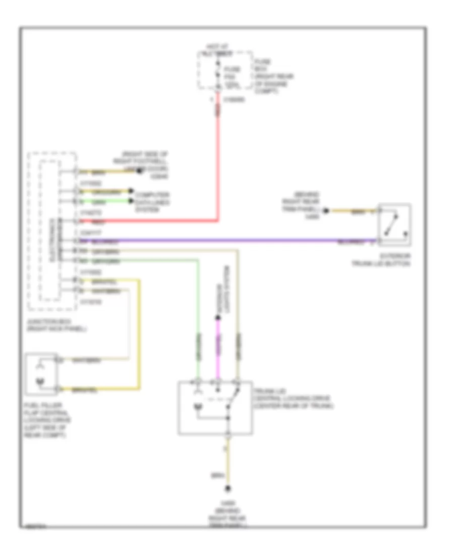
Anti-theft & Central Locking Wiring Diagram for MINI Cooper Paceman S ALL4 2014
List of elements for Anti-theft & Central Locking Wiring Diagram for MINI Cooper Paceman S ALL4 2014:
- (behind right rear trim panel) x490
- Can bus high
- Can bus low
- Computer data lines system
- Contact sig
- Driver's door system lock (rear of driver's door)
- Electronics junction box
- Exterior trunk lid button
- Footwell module (left side of left footwell)
- Fuel filler flap central locking drive (left side of rear compt)
- Fuse f11 15a
- Fuse f4 30a
- Fuse f52 40a
- Fuse f53 40a
- Fuse f8 30a
- Gnd
- Heating/air conditioning system
- Hot at all times
- Interior lights system
- Junction box (right kick panel)
- Lock sig
- Passenger's door system lock (rear of passenger's door)
- Strip switch
- Switch sig
- Term 30
- Trunk lid central locking drive (center rear of trunk)
- Unlock sig
- X11002
- X11005
- X11007
- X11010
- X14260
- X14261
- X1879
- X2042 (left side of left footwell)
- X2184 (under driver's seat)
- X256
- X257
- X2846 (right side of right footwell, under door)
- X490 (behind right rear trim panel)
BODY CONTROL MODULES
Body Control Modules Wiring Diagram for MINI Cooper Paceman S ALL4 2014
List of elements for Body Control Modules Wiring Diagram for MINI Cooper Paceman S ALL4 2014:
- (left side of left footwell) footwell module
- (left side of left footwell) x2042
- (not used)
- (under driver's seat) x2184
- Anti-theft system
- Computer data lines system
- Door locks system
- Exterior lights system
- Footwell module (left side of left footwell)
- Fuse f4 30a
- Fuse f52 40a
- Fuse f53 40a
- Fuse f8 30a
- Headlights & exterior lights systems
- Headlights system
- Hot at all times
- Interior lights system
- Junction box (right kick panel)
- Power windows system
- X11005
- X11007
- X14259
- X14260
- X14261
- X2184 (under driver's seat)
- X257
COMPUTER DATA LINES
Data Link Connector Wiring Diagram for MINI Cooper Paceman S ALL4 2014
List of elements for Data Link Connector Wiring Diagram for MINI Cooper Paceman S ALL4 2014:
- Car access system (left top side of dash)
- Ccc/ m-ask
- Dme control unit (left side of engine compt)
- Electronics junction box
- Fuse f29 5a
- Hot at all times
- Junction box (right kick panel)
- Obdii
- Socket
- Terminating resistor d-can (under left end of dash)
- X10318
- X11006
- X13812
- X14272
- X15
- X2042 (left side of left footwell)
- X60004
High/Low Bus Wiring Diagram for MINI Cooper Paceman S ALL4 2014
List of elements for High/Low Bus Wiring Diagram for MINI Cooper Paceman S ALL4 2014:
- Additional instrument
- Amplifier (behind left rear trim panel)
- Car access system (left top side of dash)
- Ccc/m-ask
- Central information display
- Comfort access control module (behind right rear trim panel)
- Dme control unit (left side of engine compt)
- Dsc senor (right passenger floor)
- Dynamic stability control (dsc) (left rear of engine compt)
- Electric steering column lock (under left side of dash)
- Electromechanical power steering (rear of engine compt)
- Footwell module (left side of left footwell)
- Heating/air conditioning system
- Intelligent battery sensor (on battery)
- Junction box (right kick panel)
- Mini joystick
- Mission control
- Multiple restraint system control unit (center console)
- Nca
- Park distance control (pdc) (right side of rear compt)
- Radio
- Steering column switch cluster
- Sunroof
- Tire pressure control (rdc) (right side of luggage compt)
- Transmission control module (a/t) (under left side of dash)
- X10179
- X10318
- X11002
- X11633
- X11634
- X13812
- X14260
- X14272
- X15
- X1879
- X1880
- X300
- X60004
- X60234
- X6060
COOLING FAN
Cooling Fan Wiring Diagram for MINI Cooper Paceman S ALL4 2014
List of elements for Cooling Fan Wiring Diagram for MINI Cooper Paceman S ALL4 2014:
- (left front of engine compt) electric fan
- 1-tier
- 2-tier
- Characteristic map thermostat (top rear center of engine)
- Computer data lines system
- Coolant pressure sensor
- Dme control unit (left side of engine compt)
- Electric fan (left front of engine compt)
- Electric fan relay
- Electric fan relay 2
- Engine controls system
- Engine temperature sensor (front of engine)
- Front power distribution box (left side of engine compt)
- Fuse f05 7.5a
- Fuse f08 40a
- Fuse fl9 50a
- Hot at all times
- Hot w/ dme relay energized
- Red
- W/ automatic engine start-stop function
- X167 (under left front of vehicle)
- X175 (left front side of engine compt)
- X4007
- X4010
- X4013
- X4014
- X60004
- X60231
CRUISE CONTROL
Cruise Control Wiring Diagram for MINI Cooper Paceman S ALL4 2014
List of elements for Cruise Control Wiring Diagram for MINI Cooper Paceman S ALL4 2014:
- (left side of left footwell) x2042
- 1.6l
- 1.6l turbo
- Accelerator pedal module (part of acceleration pedal assembly)
- Brake light switch (left side of left footwell)
- Brk light sig
- Brk test sig
- Can bus sig
- Car access system (left top side of dash)
- Clutch module (m/t) (under left side of dash)
- Computer data lines system
- Dme control unit (left side of engine compt)
- Dynamic stability control (dsc) (left rear of engine compt)
- Electric throttle valve actuator (right front of engine)
- F-can high
- F-can low
- Footwell module (left side of left footwell)
- Front power distribution box (left side of engine compt)
- Fuse f01 7.5a
- Hot at all times
- Left multi-function steering wheel switch block
- Right multi-function steering wheel switch block
- Spi interface sig
- Steering column switch cluster
- Terminal r sig
- Trans sig
- X01006
- X10318
- X14261
- X15
- X167 (under left front of vehicle)
- X1880
- X4013
- X60004
- X60211
- X60212
- X60231
- X60232
DEFOGGERS
Defoggers Wiring Diagram for MINI Cooper Paceman S ALL4 2014
List of elements for Defoggers Wiring Diagram for MINI Cooper Paceman S ALL4 2014:
- Computer data lines system
- Driver's side heated water jet
- Driver's side outside mirror
- Front power distribution box (left side of engine compt)
- Fuse f40 30a
- Fuse fl10 50a
- Heating/ air conditioning system
- Hot at all times
- Junction box (right kick panel)
- Junction box electronics
- Left heated windshield
- Nca
- Passenger's side heated water jet
- Passenger's side outside mirror
- Rear window defogger
- Rear window defogger lockout circuit (ground) (left side of rear compt door)
- Rear window defogger lockout circuit (positive) (right side of rear compt door)
- Rear window defroster
- Rear window heated relay
- Red
- Right heated windshield
- W/ rear window aerial
- W/o rear window aerial
- Windshield heater relay (left side of left footwell)
- X11002
- X11007
- X13017
- X13018
- X13443
- X13444
- X13445
- X13446
- X14272
- X151 (under front passenger's seat)
- X1879
- X2042 (left side of left footwell)
- X2184 (under driver's seat)
- X256
- X257
- X4015
- X490 (behind right rear trim panel)
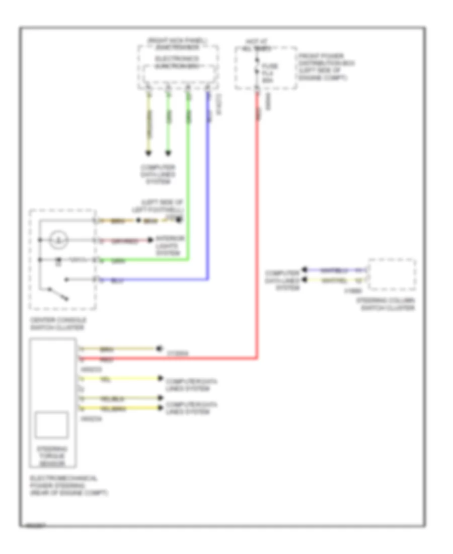
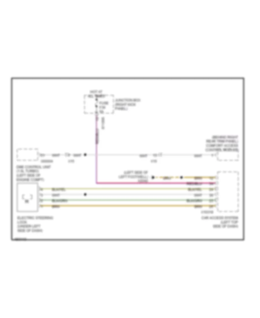
ELECTRONIC POWER STEERING
Electronic Power Steering Wiring Diagram for MINI Cooper Paceman S ALL4 2014
List of elements for Electronic Power Steering Wiring Diagram for MINI Cooper Paceman S ALL4 2014:
- (left side of left footwell) x2042
- (right kick panel) junction box
- Center console switch cluster
- Computer data lines system
- Electromechanical power steering (rear of engine compt)
- Electronics junction box
- Front power distribution box (left side of engine compt)
- Fuse fl4 80a
- Hot at all times
- Interior lights system
- Red
- Steering column switch cluster
- Steering torque sensor
- X13004
- X14272
- X1880
- X4844
- X60233
- X60234
ENGINE PERFORMANCE
1.6L
1.6L, Engine Performance Wiring Diagram (1 of 4) for MINI Cooper Paceman S ALL4 2014
List of elements for 1.6L, Engine Performance Wiring Diagram (1 of 4) for MINI Cooper Paceman S ALL4 2014:
- (top of fuel tank) electric fuel pump
- Acc gnd
- Acc pedl sens
- Acc sply
- Accelerator pedal module (part of acceleration pedal assembly)
- Act eng rly
- Act fan rly
- Act fuel pump
- Act rly
- Anti- theft system
- Anti-theft system
- Brake lt sw
- Brake vacuum sensor (left rear of engine compt)
- Brk lt sw sig
- Brk snsr
- Bsd sig
- Clutch module (m/t) (under left side of dash)
- Clutch sw
- Computer data lines system
- Cooling fans system
- Dme control unit (left side of engine compt)
- Dme rly
- Electronics junction box
- Front power distribution box (left side of engine compt)
- Fuel pump relay
- Fuse f010 15a
- Fuse f46 20a
- Gnd
- Gnd acc
- Gnd neutral
- Gnd refr
- Hot at all times
- Hot w/ terminal 30g relay energized
- Junction box (right kick panel)
- Neutral sens
- Neutral sensor
- Pa bus sig
- Pt-can hi
- Pt-can lo
- Red
- Refr pr sens
- Refrigerant pressure sensor (rear of engine compt)
- Sig
- Sply sens
- Start rly
- Start/stop function
- Starting/charging system
- Td sig
- Term 15
- Term 15 sply
- Term 30
- Term 87
- Terminal 15 relief relay
- Valvetronic
- W/ automatic engine start/stop function
- W/o automatic engine
- Wake-up sig
- X11002
- X11008
- X11010
- X151 (under front passenger's seat)
- X167 (under left front of vehicle)
- X2042 (left side of left footwell)
- X4010
- X4014
- X60004
1.6L, Engine Performance Wiring Diagram (2 of 4) for MINI Cooper Paceman S ALL4 2014
List of elements for 1.6L, Engine Performance Wiring Diagram (2 of 4) for MINI Cooper Paceman S ALL4 2014:
- (left rear of engine compt) valvetronic relay
- (top left side of engine)
- Brake light switch (left side of left footwell)
- Cooling fans system
- Crankcase ventilation heating relay
- Dme relay
- Engine breather heater 1 (right rear side of engine)
- Exterior lights system
- Front power distribution box (left side of engine compt)
- Fuel tank leakage diagnostic module (front of right rear wheel)
- Fuse box (right rear of engine compt)
- Fuse f01 7.5a
- Fuse f02 25a
- Fuse f03 20a
- Fuse f04 20a
- Fuse f05 7.5a
- Fuse f07 7.5a
- Fuse f67 150a
- Fuse f68 40a
- Hot at all times
- Ignition coil 1
- Ignition coil 2
- Ignition coil 3
- Ignition coil 4
- Interference suppression capacitor (top right side of engine)
- Red
- X13020
- X175 (left front side of engine compt)
- X2042 (left side of left footwell)
- X4009
- X4010
- X4013
- X5353
- X6401
- X64561 (center of top left side of engine)
- X65399
1.6L, Engine Performance Wiring Diagram (3 of 4) for MINI Cooper Paceman S ALL4 2014
List of elements for 1.6L, Engine Performance Wiring Diagram (3 of 4) for MINI Cooper Paceman S ALL4 2014:
- (bottom of exhaust pipe) oxygen sensor (behind catalytic converter)
- (right front of engine) electric throttle valve actuator
- (right rear of engine) crankshaft sensor
- (top of exhaust pipe) oxygen sensor (before catalytic converter)
- (top right rear side of engine) engine coolant temperature sensor
- Act oil pr ctrl
- Act sol vlve exh
- Act sol vlve int
- Crankshaft sens
- Dme control unit (left side of engine compt)
- Eccentric shaft sensor (top right rear side of engine)
- Elct vlve actutor
- Gnd elct sens
- Gnd int sens
- Hot-film air mas
- Int sply sens
- Intake camshaft sensor (top right rear side of engine)
- Nca
- Shft sens
- Sig exh sens
- Sig ful inj
- Sig ig coil
- Sig int sens
- X60212
1.6L, Engine Performance Wiring Diagram (4 of 4) for MINI Cooper Paceman S ALL4 2014
List of elements for 1.6L, Engine Performance Wiring Diagram (4 of 4) for MINI Cooper Paceman S ALL4 2014:
- (front center of engine) friction wheel drive
- (left side of engine) engine oil pressure sensor
- (right rear of engine) valvetronic servo motor
- (right side of engine) knock sensor
- (top right rear side of engine)
- (top right side of engine)
- Act oxygen sens
- Act sens heater
- Characteristic map thermostat (right rear side of engine)
- Crnkshaft sens
- Dme control unit (left side of engine compt)
- Elct actuator
- Eng oil pr sens
- Eng temp sens
- Eng temp sig
- Exh sens
- Exhaust camshaft sensor
- Exhaust vanos solenoid valve (top right front side of engine)
- Fuel injection 1
- Fuel injection 2
- Fuel injection 3
- Fuel injection 4
- Fuel tank vent valve (top left of engine)
- Fuel vet valve
- Fuil inj
- Hot-film air mas
- Hot-film air mass meter (top rear center of engine)
- Int temp sens
- Intake temperature differential pressure sensor (right rear side of engine)
- Intake vanos solenoid valve (right front side of engine)
- Knock sens
- Map thermostat
- Nca
- Oil pressure regulating valve (front right side of engine)
- Oxygen sens
- Oxygen sens sig
- Pr sens
- Sig vlve
- Sply
- Term 15
- Term 87
- Valve servo
- Wheel drive
- X60211
1.6L TURBO
1.6L Turbo, Engine Performance Wiring Diagram (1 of 4) for MINI Cooper Paceman S ALL4 2014
List of elements for 1.6L Turbo, Engine Performance Wiring Diagram (1 of 4) for MINI Cooper Paceman S ALL4 2014:
- Accelerator pedal module (part of acceleration pedal assembly)
- Act dme relay
- Act heating rly
- Activation rly
- Activation rly 2
- Anti-theft system
- Brake light sig
- Brake light switch (left side of left footwell)
- Brake vacuum sensor (left rear of engine compt)
- Brk light sig
- Bsd sig
- Clutch module (m/t) (under left side of dash)
- Computer data lines system
- Cooling fans system
- Dme control unit (left side of engine compt)
- Electric fuel pump (top of fuel tank)
- Electronics junction box
- Exterior lights system
- Front power distribution box (left side of engine compt)
- Fuel pump relay
- Fuel tank sig
- Fuse f01 7.5a
- Fuse f010 15a
- Fuse f46 20a
- Gnd
- Gnd sens
- Hot at all times
- Hot w/ terminal 30g relay energized
- Junction box (right kick panel)
- Neutral sensor
- Pa bus sig
- Pt can high
- Pt can low
- Red
- Refrigerant pressure sensor (rear of engine compt)
- Sens sig
- Sig switch
- Sply sens
- Start sig
- Starting/charging system
- Td sig
- Terminal 15 relief relay
- Terminal 15 sply
- Terminal 30
- Terminal 87 sply
- Valvetronic rly
- Valvetronic rly act
- W/ automatic engine start/stop function
- W/o automatic engine start/stop function
- Wake up sig
- X11002
- X11008
- X11010
- X151 (under front passenger's seat)
- X167 (under left front of vehicle)
- X2042 (left side of left footwell)
- X4010
- X4013
- X4014
- X60004
1.6L Turbo, Engine Performance Wiring Diagram (2 of 4) for MINI Cooper Paceman S ALL4 2014
List of elements for 1.6L Turbo, Engine Performance Wiring Diagram (2 of 4) for MINI Cooper Paceman S ALL4 2014:
- (left rear of engine compt) valvetronic relay
- (top of engine)
- Cooling fans system
- Crankcase ventilation heating relay
- Dme relay
- Engine breather heater 1 (right rear side of engine)
- Front power distribution box (left side of engine compt)
- Fuel tank leakage diagnostic module (front of right rear wheel)
- Fuse box (right rear of engine compt)
- Fuse f02 25a
- Fuse f03 20a
- Fuse f04 20a
- Fuse f05 7.5a
- Fuse f07 7.5a
- Fuse f67 150a
- Fuse f68 40a
- Hot at all times
- Ignition coil 1
- Ignition coil 2
- Ignition coil 3
- Ignition coil 4
- Interference suppression capacitor (top right side of engine)
- Red
- Valvetronic servo motor (right rear of engine)
- X13020
- X175 (left front side of engine compt)
- X4009
- X4010
- X4013
- X5353
- X6401
- X64561 (center of top left side of engine)
- X65399
1.6L Turbo, Engine Performance Wiring Diagram (3 of 4) for MINI Cooper Paceman S ALL4 2014
List of elements for 1.6L Turbo, Engine Performance Wiring Diagram (3 of 4) for MINI Cooper Paceman S ALL4 2014:
- (bottom of exhaust pipe) oxygen sensor behind catalytic converter
- (front center of engine) friction wheel drive
- (right front of engine) electric throttle valve actuator
- (right side of engine) rail pressure sensor
- (top of exhaust pipe) oxygen sensor before catalytic converter
- (top rear center of engine) (w/ high pressure pump) volume control valve
- (top right side of engine)
- Crankcase ventilation bypass
- Dme control unit (left side of engine compt)
- Fuel injection 1
- Fuel injection 2
- Fuel injection 3
- Fuel injection 4
- Gnd actuator
- Gnd friction
- Gnd pump
- Gnd sens
- Ign coil 1 sig
- Ign coil 2 sig
- Ign coil 3 sig
- Ign coil 4 sig
- Inj 1 sig
- Inj 2 sig
- Inj 3 sig
- Inj 4 sig
- Nca
- Pvc heater
- Sig meter
- Sig motor
- Sig oil press
- Sig sens
- Sig vlv
- Sply motor
- Sply sens
- Term 15 sply
- Vlv acti
- Vlvetronic gnd
- Vlvetronic sig
- X60232
1.6L Turbo, Engine Performance Wiring Diagram (4 of 4) for MINI Cooper Paceman S ALL4 2014
List of elements for 1.6L Turbo, Engine Performance Wiring Diagram (4 of 4) for MINI Cooper Paceman S ALL4 2014:
- (front right side of engine) oil pressure regulating valve
- (left rear of engine) turbocharger coolant pump
- (right side of engine) knock sensor
- (top front center of engine) intake air temperature/ boost pressure sensor
- (top rear center of engine) (w/o high pressure pump) volume control valve
- (top rear center of engine) characteristic map thermostat
- (top rear center of engine) intake camshaft sensor
- (top right rear side of engine) engine coolant temperature sensor
- Acti sens
- Acti servo motor
- Acti vlv
- Crankshaft sensor (right rear of engine)
- Dme control unit (left side of engine compt)
- Eng temp sens
- Engine oil pressure sensor (left side of engine)
- Exhaust camshaft sensor
- Exhaust vanos solenoid valve
- Fuel tank vent valve (top left of engine)
- Gnd actuator
- Gnd meter
- Gnd sens
- Gnd servo motor
- Hot-film air mass meter (top rear center of engine)
- Intake pipe pressure sensor
- Intake vanos solenoid valve (right front side of engine)
- Nca
- Plug in jumper
- Sig actuator
- Sig pump
- Sig sens
- Sig temp
- Sig thermostat
- Sig vlv
- Sply actuator
- Sply sens
- Term 15
- Term 15 sply
- Term 87
- Thrust air control valve (top left rear side of engine)
- Wastegate valve (right side of engine)
- X60231
EXTERIOR LIGHTS
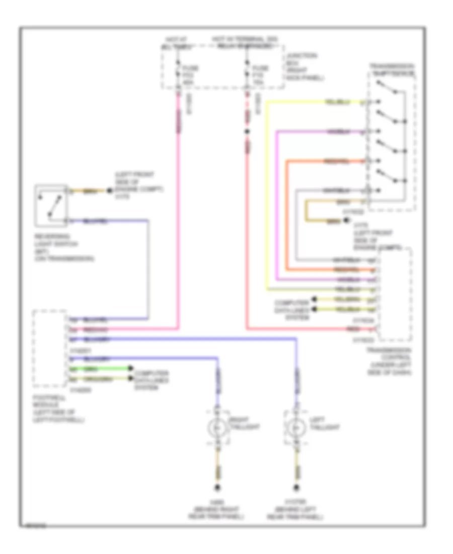
Backup Lamps Wiring Diagram for MINI Cooper Paceman S ALL4 2014
List of elements for Backup Lamps Wiring Diagram for MINI Cooper Paceman S ALL4 2014:
- (left front side of engine compt) x175
- Computer data lines system
- Footwell module (left side of left footwell)
- Fuse f15 15a
- Fuse f53 40a
- Hot at all times
- Hot w/ terminal 30g relay energized
- Junction box (right kick panel)
- Left taillight
- Red
- Reversing light switch (m/t) (on transmission)
- Right taillight
- Transmission control (under left side of dash)
- Transmission shift device
- X11003
- X11005
- X11632
- X11633
- X11634
- X13795 (behind left rear trim panel)
- X14260
- X14261
- X175 (left front side of engine compt)
- X490 (behind right rear trim panel)
Exterior Lamps Wiring Diagram (1 of 2) for MINI Cooper Paceman S ALL4 2014
List of elements for Exterior Lamps Wiring Diagram (1 of 2) for MINI Cooper Paceman S ALL4 2014:
- Computer data lines system
- Direction indicator light
- Fuse f3 30a
- Fuse f43 20a
- Fuse f52 40a
- Fuse f7 20a
- Hot at all times
- Hot w/ bi-stable relay energized
- Junction box (right kick panel)
- Left front side marker light
- Left headlamp
- Left license plate light
- Left rear side marker light
- Right front direction indicator light repeater
- Right front side marker light
- Right headlamp
- Right license plate light
- Right rear side marker light
- Trailer module (right rear quarterpanel)
- Trailer socket
- X11001
- X11003
- X11005
- X13795 (behind left rear trim panel)
- X165 (front of right front wheel)
- X175 (left front side of engine compt)
Exterior Lamps Wiring Diagram (2 of 2) for MINI Cooper Paceman S ALL4 2014
List of elements for Exterior Lamps Wiring Diagram (2 of 2) for MINI Cooper Paceman S ALL4 2014:
- (left side of left footwell) x2042
- Auxiliary brake light
- Brake light switch (left side of left footwell)
- Car access system (left top side of dash)
- Computer data lines system
- Dme control unit (left side of engine compt)
- Dynamic stability control (dsc) (left rear of engine compt)
- Footwell module (left side of left footwell)
- Hazard warning switch
- Interference suppressor filter 2
- Left front direction indicator light repeater
- Left side marker/ fog light
- Left taillight
- Lights/direction indicator/low beam stalk
- Right side marker/ fog light
- Right taillight
- Steering column switch cluster
- W/ interference suppressor filter
- W/o interference suppressor filter
- X10318
- X10900
- X10901
- X129
- X136
- X13795 (behind left rear trim panel)
- X14259
- X14260
- X14261
- X165 (front of right front wheel)
- X175 (left front side of engine compt)
- X1880
- X2042 (left side of left footwell)
- X490 (behind right rear trim panel)
- X60004
GROUND DISTRIBUTION
Ground Distribution Wiring Diagram (1 of 3) for MINI Cooper Paceman S ALL4 2014
List of elements for Ground Distribution Wiring Diagram (1 of 3) for MINI Cooper Paceman S ALL4 2014:
- (a/t) gear indicator lighting
- (if equipped) interference suppressor filter 2
- (right kick panel) junction box
- (w/ individual horn) horn
- (w/ rear window aerial) rear window defroster
- (w/ twin horn) horn
- (w/ twin horn) horn 2
- (w/o rear window aerial) rear window defogger lockout circuit
- Auxiliary brake light
- Battery
- Comfort access control module
- Compressor clutch
- Dsc sensor
- Exterior trunk lid button
- Ignition coil cylinder
- Intelligent battery sensor
- Interference suppression capacitor for ignition coils
- Nca
- Passenger's door system lock
- Passenger's seat heating module
- Rear driver's side courtesy lighting
- Rear wiper drive
- Right front direction indicator light repeater
- Right front make-up mirror light
- Right front side marker light
- Right headlight
- Right side marker/ fog light
- Right taillight
- Selector lever position switch
- Siren w/ tilt alarm sensor
- Tire pressure control
- Transmission control
- Trunk lid central locking drive
- W/ led
- W/ xenon
- W/o led
- W/o xenon
- X013709
- X10901
- X11002
- X11007
- X11633
- X13018
- X136
- X165 (front of right front wheel)
- X256
- X279
- X2846 (right side of right footwell, under door)
- X490 (behind right rear trim panel)
- X5550
- X6402
- X64561 (center of top left side of engine)
- X9039
Ground Distribution Wiring Diagram (2 of 3) for MINI Cooper Paceman S ALL4 2014
List of elements for Ground Distribution Wiring Diagram (2 of 3) for MINI Cooper Paceman S ALL4 2014:
- (a/t) transmission shift device
- (m/t) clutch module
- (m/t) reversing light switch
- Active sound design
- Additional instrument
- Automatic a/c
- Base plate
- Blower motor
- Blower output stage
- Brake fluid level switch
- Brake light switch
- Car access system
- Center console switch cluster
- Central rail lighting 1
- Central rail lighting 2
- Combox
- Driver door oddments compartment lighting
- Driver's door courtesy lighting
- Driver's door entrance light
- Driver's door handle plate lighting
- Driver's door switch block
- Driver's seat belt buckle contact
- Driver's seat heating module
- Driver's seat position sensor
- Driver's side heated washer nozzle
- Driver's side outside mirror
- Electric fan
- Engine breather heater 1
- Footwell module
- Front cigar lighter
- Front interior light
- Front passenger's seat position sensor
- Front power distribution box
- Fuel heater
- Hazard warning switch
- Headlight washer pump
- Heating/air conditioning system
- Hood contact switch
- Instrument cluster control module
- Left front direction indicator light repeater
- Left front side marker light
- Left headlight
- Left heated windscreen
- Left side marker/ fog light
- Manual a/c
- Mini joystick
- Multiple restraint system control unit
- Nca
- Obdii socket
- Passenger's seat belt buckle contact
- Passenger's seat occupancy detection
- Passenger's side heated washer nozzle
- Radio
- Steering column switch cluster
- Usb hub
- W/ led
- W/ xenon
- W/o led
- W/o xenon
- Washer fluid level switch
- Wiper module
- X10318
- X11632
- X129
- X13016 (behind left rear trim panel)
- X13443
- X13709
- X13812
- X14261
- X15
- X17177
- X175 (left front side of engine compt)
- X18069
- X1879
- X1880
- X2042 (left side of left footwell)
- X257
- X275
- X279
- X34130
- X4013
- X46 (under center console)
- X5549
- X6056
- X65399
- X9024
- X9331
Ground Distribution Wiring Diagram (3 of 3) for MINI Cooper Paceman S ALL4 2014
List of elements for Ground Distribution Wiring Diagram (3 of 3) for MINI Cooper Paceman S ALL4 2014:
- (not used)
- (right kick panel) junction box
- All-wheel drive vehicle clutch shield
- Amplifier
- Car access system
- Center rail lighting
- Dc/dc converter
- Dme control unit
- Driver's door system lock
- Dynamic stability control (dsc)
- Electric fuel pump
- Electro- mechanical power steering
- Electrochromic interior rear view mirror
- Footwell module
- Front passenger's door handle plate lighting
- Glove compartment light
- Inner tailgate push-button
- Interior movement detector
- Left front footwell light
- Left front make-up mirror light
- Left license plate light
- Left rear side marker light
- Left taillight
- Luggage compartment charging socket
- Nca
- Park distance control (pdc)
- Passenger's door courtesy light
- Passenger's door entrance light
- Passenger's door oddments compartment lighting
- Passenger's door power window switch
- Passenger's side outer door handle button
- Passenger's side outside mirror
- Rain/ headlight sensor
- Rear cigarette lighter
- Rear passenger's side courtesy lighting
- Rear socket 2
- Rear socket outlet
- Right front footwell light
- Right heated windshield
- Right license plate light
- Right rear side marker light
- Roof operating unit
- Slide/ tilt sunroof control module
- Steering column switch cluster
- Trailer module
- Trailer socket
- W/ high equipment variant
- W/ low equipment variant
- Windshield heater relay
- X11007
- X13004
- X13446
- X13795 (behind left rear trim panel)
- X14260
- X14261
- X151 (under front passenger's seat)
- X167 (under left front of vehicle)
- X19527
- X2184 (under driver's seat)
- X256
- X257
- X300
- X4 (top of left front wheel)
- X60004
- X60233
- X9331
HEADLIGHTS
Headlights Wiring Diagram (1 of 2) for MINI Cooper Paceman S ALL4 2014
List of elements for Headlights Wiring Diagram (1 of 2) for MINI Cooper Paceman S ALL4 2014:
- (left side of left footwell) x2042
- (left top side of dash) car access system
- Adaptive headlight module
- Computer data lines system
- Electronics junction box
- Footwell module (left side of left footwell)
- Fuse f19 5a
- Fuse f52 40a
- Fuse f53 40a
- Headlamp range control
- Headlamp range control position motor
- High beam
- Hot at all times
- Hot w/ terminal 30g relay energized
- Junction box (right kick panel)
- Left headlight
- Low beam
- Parking brake warning switch (center console)
- Right headlight
- Swiveling module
- W/ led
- W/ xenon headlight
- W/o led
- W/o xenon headlight
- X11002
- X11005
- X11008
- X14259
- X14260
- X14261
- X14272
- X15
- X165 (front of right front wheel)
- X175 (left front side of engine compt)
- Xenon headlight bulb
- Xenon lamps module
Headlights Wiring Diagram (2 of 2) for MINI Cooper Paceman S ALL4 2014
List of elements for Headlights Wiring Diagram (2 of 2) for MINI Cooper Paceman S ALL4 2014:
- (front of right front wheel) x165
- (left front side of engine compt) x175
- (windshield top) rain/light sensor
- Headlamp range control position motor
- Left front level sensor
- Left rear level sensor
- Left side marker/ fog light (w/o led)
- Left side marker/fog light (w/ led)
- Lights/direct indicator/low beam stalk
- Right headlight
- Right side marker/fog light (w/ led)
- Right side marker/fog light (w/o led)
- Steering column switch cluster
- X165 (front of right front wheel)
- X1880
- X2184 (under driver's seat)
- X768
- X769
- X9024
- X9039
- Xenon headlight bulb
- Xenon lamps module
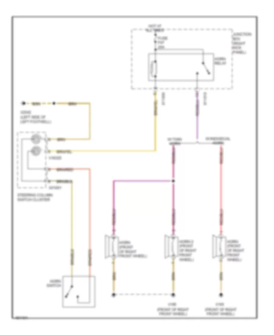
HORN
Horn Wiring Diagram for MINI Cooper Paceman S ALL4 2014
List of elements for Horn Wiring Diagram for MINI Cooper Paceman S ALL4 2014:
- (front of right front wheel)
- (left side of left footwell)
- Fuse f47 20a
- Horn (front of right front wheel)
- Horn 2 (front of right front wheel)
- Horn relay
- Horn switch
- Hot at all times
- Junction box (right kick panel)
- Steering column switch cluster
- W/ individual horn
- W/ twin horn
- X01001
- X11006
- X11010
- X165
- X18325
- X2042
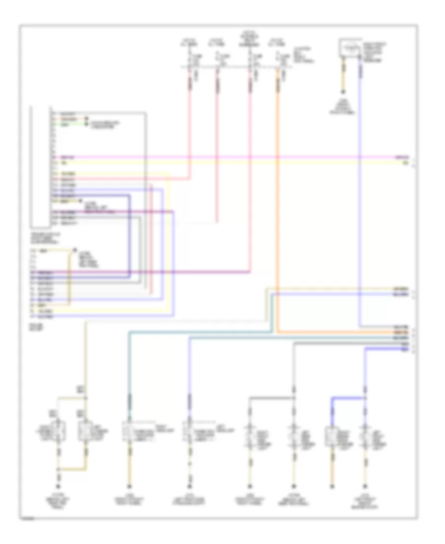
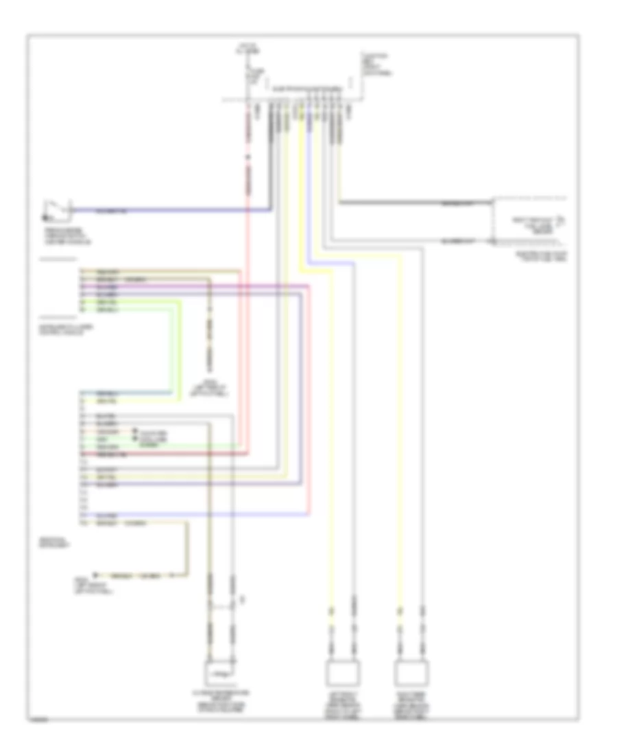
INSTRUMENT CLUSTER
Instrument Cluster Wiring Diagram for MINI Cooper Paceman S ALL4 2014
List of elements for Instrument Cluster Wiring Diagram for MINI Cooper Paceman S ALL4 2014:
- Additional instrument
- Computer data lines system
- Electric fuel pump (top of fuel tank)
- Electronics junction box
- Fuse f29 5a
- Hot at all times
- Instrument cluster control module
- Junction box (right kick panel)
- Left front brake pad wear sensor (front of left front wheel)
- Nca
- Outside temperature sensor (behind right side of front bumper)
- Parking brake warning switch (center console)
- Right rear brake pad wear sensor (behind right rear wheel)
- Right tank half fuel level sensor
- X11002
- X11006
- X14272
- X15
- X2042 (left side of left footwell)
INTERIOR LIGHTS
Courtesy Lamps Wiring Diagram (1 of 3) for MINI Cooper Paceman S ALL4 2014
List of elements for Courtesy Lamps Wiring Diagram (1 of 3) for MINI Cooper Paceman S ALL4 2014:
- Center rail lighting 1
- Center rail lighting 2
- Center rail lighting 3
- Center rail lighting 4
- Computer data lines system
- Footwell module (left side of left footwell)
- Front interior light
- Fuse f4 30a
- Hot at all times
- Instrument illumination circuit
- Junction box (right kick panel)
- Nca
- Passenger's door courtesy light
- Passenger's door handle plate lighting
- Rear driver's side courtesy lighting
- Rear passenger's side courtesy lighting
- Roof operating unit
- Top light
- X11007
- X13795 (behind left rear trim panel)
- X14259
- X14260
- X14261
- X14286
- X14288
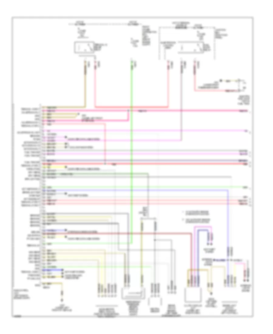
- X151 (under front passenger's seat)
- X2042 (left side of left footwell)
- X2184 (under driver's seat)
- X256
- X490 (behind right rear trim panel)
Courtesy Lamps Wiring Diagram (2 of 3) for MINI Cooper Paceman S ALL4 2014
List of elements for Courtesy Lamps Wiring Diagram (2 of 3) for MINI Cooper Paceman S ALL4 2014:
- Driver's door courtesy light
- Driver's door handle plate lighting
- Driver's door oddments compartment lighting
- Left front footwell light
- Passenger's door oddments compartment lighting
- Right front footwell light
- X151 (under front passenger's seat)
- X2042 (left side of left footwell)
- X257
- X3279 (behind right center of dash)
- X3456 (behind right center of dash)
Courtesy Lamps Wiring Diagram (3 of 3) for MINI Cooper Paceman S ALL4 2014
List of elements for Courtesy Lamps Wiring Diagram (3 of 3) for MINI Cooper Paceman S ALL4 2014:
- Driver's door entrance light
- Front interior light
- Fuse f16 10a
- Fuse f20 10a
- Glove compartment light
- Hot w/ terminal 30g relay energized
- Junction box (right kick panel)
- Left front make-up mirror light
- Luggage compartment light
- Passenger's door entrance light
- Right front make-up mirror light
- Trunk lid central locking drive (center rear of trunk)
- W/ light package
- W/o light package
- X11006
- X11007
- X151 (under front passenger's seat)
- X2042 (left side of left footwell)
- X2184 (under driver's seat)
- X256
- X257
- X2846 (right side of right footwell, under door)
- X490 (behind right rear trim panel)
Instrument Illumination Wiring Diagram for MINI Cooper Paceman S ALL4 2014
List of elements for Instrument Illumination Wiring Diagram for MINI Cooper Paceman S ALL4 2014:
- (left side of left footwell) x2042
- (under driver's seat) x2184
- Ccc/champ
- Ccc/m-ask
- Cd changer
- Center console switch cluster
- Computer data lines system
- Footwell module (left side of left footwell)
- Fuse f4 30a
- Gear indicator lighting (a/t)
- Heating/air conditioning system
- Hot at all times
- Junction box (right kick panel)
- Lights/direct indicator/low beam stalk
- Passenger's door handle plate lighting (w/ ambient lighting, 3rd color)
- Passenger's door oddments compartment lighting (w/ ambient lighting, 3rd color)
- Radio
- Rear passenger's side power window switch
- Roof operating unit
- Steering column switch cluster
- W/ ccc/champ
- W/ ccc/m-ask
- W/ high variant
- W/ low variant
- W/ radio
- X11007
- X13016 (behind left rear trim panel)
- X13425
- X13812
- X14259
- X14260
- X14261
- X14286
- X14487
- X151 (under front passenger's seat)
- X18180
- X1879
- X1880
- X2042 (left side of left footwell)
- X2846 (right side of right footwell, under door)
- X9331
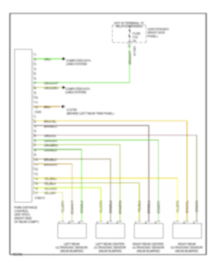
NAVIGATION
Navigation Wiring Diagram for MINI Cooper Paceman S ALL4 2014
List of elements for Navigation Wiring Diagram for MINI Cooper Paceman S ALL4 2014:
- Computer data lines system
- Fuse f32 5a
- Hot w/ terminal 15 relay energized
- Junction box (right kick panel)
- Left rear center ultrasonic sensor (rear bumper)
- Left rear ultrasonic sensor (rear bumper)
- Park distance control unit (pdc) (right side of rear compt)
- Right rear center ultrasonic sensor (rear bumper)
- Right rear ultrasonic sensor (rear bumper)
- X11001
- X13795 (behind left rear trim panel)
- X18013
- X300
POWER DISTRIBUTION
Power Distribution Wiring Diagram (1 of 3) for MINI Cooper Paceman S ALL4 2014
List of elements for Power Distribution Wiring Diagram (1 of 3) for MINI Cooper Paceman S ALL4 2014:
- (not used)
- (right kick panel) junction box
- 1.6l
- 1.6l turbo
- A/c compressor relay
- Additional instrument
- Alternator
- Amplifier (if equipped)
- Battery
- Car access system
- Dme control module
- Driver's seat heating module
- Dynamic stability control (dsc)
- Electro- mechanical power steering
- Electrochromic interior rear view mirror
- Footwell module
- Front washer pump relay
- Fuel injectors relay
- Fuel pump relay
- Fuse box (right rear of engine compt)
- Fuse f10 10a
- Fuse f10 30a
- Fuse f11 15a
- Fuse f2 30a
- Fuse f24 10a
- Fuse f25 15a
- Fuse f26 5a
- Fuse f27 7.5a
- Fuse f28 15a
- Fuse f29 5a
- Fuse f3 30a
- Fuse f36 5a
- Fuse f39 5a
- Fuse f4 30a
- Fuse f40 30a
- Fuse f41 30a
- Fuse f42 30a
- Fuse f43 20a
- Fuse f46 20a
- Fuse f47 20a
- Fuse f48 30a
- Fuse f49 30a
- Fuse f50 15a
- Fuse f51 40a
- Fuse f52 40a
- Fuse f53 40a
- Fuse f60 125a
- Fuse f67 150a
- Fuse f68 40a
- Fuse f8 30a
- Fuse f9 30a
- Headlight cleaning system relay
- Heater blower relay
- Horn relay
- Intelligent battery sensor (on battery)
- Junction box (right kick panel)
- Nca
- Obdii socket
- Passenger's seat heating module
- Rear driver's side power window relay
- Rear washer pump relay
- Rear window defroster relay
- Rear window wiper relay
- Red
- Selector lever position switch
- Siren w/ tilt alarm sensor
- Start stop unit
- Starter
- Steering column switch cluster
- To electronics junction box (diagram 3 of 3)
- To front power distribution box (diagram 2 of 3)
- Trailer module
- Transmission control module (a/t)
- Usb hub (w/ combox)
- Valvetronic relay
- X013709
- X10318
- X11001
- X11002
- X11005
- X11006
- X11007
- X11008
- X11009
- X11633
- X13020
- X13709
- X14027
- X14260
- X14261
- X14272
- X15
- X1716
- X17177
- X18090
- X1880
- X2498
- X275
- X279
- X34117
- X60004
- X60234
- X6060
- X6401
- X6402
Power Distribution Wiring Diagram (2 of 3) for MINI Cooper Paceman S ALL4 2014
List of elements for Power Distribution Wiring Diagram (2 of 3) for MINI Cooper Paceman S ALL4 2014:
- (left side of engine compt) front power distribution box
- (not used)
- (right kick panel) junction box
- (right side of right footwell, under door) x2846
- 1.6l
- 1.6l turbo
- Auc sensor
- Baseplate
- Car access system
- Combox
- Crankcase ventilation heater relay
- Dc/dc converter (under left side of dash)
- Dme control unit
- Dme relay
- Driver's seat heating module
- Dsc sensor
- Dynamic stability control (dsc)
- Electric fan relay
- Electric fan relay 2 (1.6l turbo)
- Electro- mechanical power steering
- Electrochromic interior rearveiw mirror
- Electronics junction box
- From fuse box (diagram 1 of 3)
- From fuse f13 (diagram 3 of 3)
- From junction box (diagram 3 of 3)
- From terminal 15 relay (diagram 3 of 3)
- Front cigar lighter
- Fuse f01 7.5a
- Fuse f010 15a
- Fuse f06 25a
- Fuse f07 7.5a
- Fuse f08 40a
- Fuse f09 30a
- Fuse f12 5a
- Fuse f32 5a
- Fuse f33 5a
- Fuse f34 7.5a
- Fuse f35 5a
- Fuse f44 20a
- Fuse fl10 50a
- Fuse fl12 30a
- Fuse fl3 40a
- Fuse fl4 80a
- Fuse fl6 40a
- Fuse fl9 50a
- Luggage compartment charging socket
- Mirror adjustment switch
- Nca
- Park distance control (pdc)
- Passenger's seat heating module
- Rear cigarette lighter
- Rear socket 2
- Rear socket outlet
- Red
- Terminal 15 relief relay
- To junction box (diagram 3 of 3)
- Ulf sbx (if equipped)
- Ulf sbx h (if equipped)
- Usb hub
- W/ combox
- W/o combox
- Windscreen heater relay
- Wiper relay 1
- Wiper relay 2
- X013709
- X10318
- X11001
- X11002
- X11003
- X11007
- X11008
- X13566
- X13709
- X14133
- X15
- X151 (under front passenger's seat)
- X17177
- X17397
- X2042 (left side of left footwell)
- X257
- X275
- X279
- X300
- X34130
- X4010
- X4013
- X4015
- X4545
- X4844
- X60004
- X60233
- X625
Power Distribution Wiring Diagram (3 of 3) for MINI Cooper Paceman S ALL4 2014
List of elements for Power Distribution Wiring Diagram (3 of 3) for MINI Cooper Paceman S ALL4 2014:
- (not used)
- Bi stable relay (variant- dependent)
- Car access system
- Ccc/ m-ask
- Central information display
- Comfort access control unit
- Driver's door switch block
- Driver's side outside mirror
- Dynamic stability control (dsc)
- Electronics junction box
- From b fuse f28 (diagram 1 of 3)
- From converter dc/dc (diagram 2 of 3)
- From dc/dc converter (diagram 2 of 3)
- Front interior light
- Fuel pump relay
- Fuse f13 10a
- Fuse f14 10a
- Fuse f15 15a
- Fuse f16 10a
- Fuse f17 10a
- Fuse f18 5a
- Fuse f19 5a
- Fuse f20 10a
- Fuse f21 10a
- Fuse f22 7.5a
- Fuse f23 10a
- Fuse f45 20a
- Fuse f6 30a
- Fuse f7 20a
- Glove compartment light
- Heating/ air conditioning system
- Jbe high
- Jbe high w/ msa
- Jbe low (or) high
- Junction box (right kick panel)
- Left front make up mirror light
- Luggage compartment light
- Mini joystick
- Mission control
- Nca
- Passenger's side outside mirror
- Radio
- Rain/ headlight sensor
- Red
- Right front make up mirror light
- Roof operating unit
- Selector lever position switch
- Steering column switch cluster
- Sunroof
- Terminal 30g relay
- Terminal relay
- Tire pressure control
- To dc/dc converter (diagram 2 of 3)
- To fuse f12 (diagram 2 of 3)
- To fuse f33 (diagram 2 of 3)
- Trailer socket (coupe & clubman)
- Transmission control (a/t)
- Transmission shift device
- W/ light package
- W/ radio
- W/o radio
- X10318
- X11001
- X11002
- X11003
- X11006
- X11007
- X11008
- X11009
- X11632
- X11633
- X13812
- X14286
- X15
- X1879
- X1880
- X256
- X257
- X2846 (right side of right footwell, under door)
- X9270
- X9997
POWER DOOR LOCKS
Power Door Locks Wiring Diagram for MINI Cooper Paceman S ALL4 2014
List of elements for Power Door Locks Wiring Diagram for MINI Cooper Paceman S ALL4 2014:
- (behind right rear trim panel) x490
- Can bus high
- Can bus low
- Computer data lines system
- Contact sig
- Driver's door system lock (rear of driver's door)
- Electronics junction box
- Exterior trunk lid button
- Footwell module (left side of left footwell)
- Fuel filler flap central locking drive (left side of rear compt)
- Fuse f11 15a
- Fuse f4 30a
- Fuse f52 40a
- Fuse f53 40a
- Fuse f8 30a
- Gnd
- Heating/air conditioning system
- Hot at all times
- Interior lights system
- Junction box (right kick panel)
- Lock sig
- Passenger's door system lock (rear of passenger's door)
- Strip switch
- Switch sig
- Term 30
- Trunk lid central locking drive (center rear of trunk)
- Unlock sig
- X11002
- X11005
- X11007
- X11010
- X14260
- X14261
- X1879
- X2042 (left side of left footwell)
- X2184 (under driver's seat)
- X256
- X257
- X2846 (right side of right footwell, under door)
- X490 (behind right rear trim panel)
POWER MIRRORS
Electrochromic Mirror Wiring Diagram for MINI Cooper Paceman S ALL4 2014
List of elements for Electrochromic Mirror Wiring Diagram for MINI Cooper Paceman S ALL4 2014:
- Car access system (left top side of dash)
- Comfort access control module (behind right rear trim panel)
- Driver's side outside mirror
- Electrochromic interior rear view mirror
- Fbd receiver
- Fuse f26 5a
- Fuse f34 7.5a
- Hot at all times
- Hot w/ terminal 15 relay energized
- Junction box (right kick panel)
- Junction box electronics
- Nca
- Passenger's side outside mirror
- X10318
- X11002
- X11008
- X15
- X2184 (under driver's seat)
- X256
- X257
Power Mirrors Wiring Diagram for MINI Cooper Paceman S ALL4 2014
List of elements for Power Mirrors Wiring Diagram for MINI Cooper Paceman S ALL4 2014:
- (left side of left footwell) x2042
- (right kick panel) junction box
- (under front passenger's seat) x151
- Adjustment drive
- Driver's door switch block
- Driver's side outside mirror
- Electrochromic mirror circuits
- Electronics junction box
- Fold-in motor
- Footwell module (left side of left footwell)
- Fuse f14 10a
- Fuse f22 7.5a
- Heating
- Horizontal
- Hot w/ terminal 30g relay energized
- Motor fold-in
- Nca
- Passenger's side outside mirror
- Vertical
- Wiper/washer system
- X11002
- X11006
- X11008
- X14260
- X15
- X256
- X257
POWER SEATS
Power Seats Wiring Diagram for MINI Cooper Paceman S ALL4 2014
List of elements for Power Seats Wiring Diagram for MINI Cooper Paceman S ALL4 2014:
- Computer data lines system
- Driver's seat backrest heating
- Driver's seat cushion heating
- Driver's seat heating module
- Electronics junction box
- Fuse f34 7.5a
- Fuse f41 30a
- Fuse f42 30a
- Heating/air conditioning system
- Hot at all times
- Hot w/ terminal 15 relay energized
- Junction box (right kick panel)
- Nca
- Passenger's seat backrest heating
- Passenger's seat cushion heating
- Passenger's seat heating module
- X013709
- X0732
- X0733
- X11001
- X11002
- X11008
- X13709
- X1879
- X2042 (left side of left footwell)
- X275
- X279
- X2846 (right side of right footwell, under door)
- X732
- X733
POWER TOP/SUNROOF
Power Top/Sunroof Wiring Diagram for MINI Cooper Paceman S ALL4 2014
List of elements for Power Top/Sunroof Wiring Diagram for MINI Cooper Paceman S ALL4 2014:
- Close slide/ tilt sunroof switch
- Computer data lines system
- Fuse f6 30a
- Hot w/ terminal 30g relay energized
- Junction box (right kick panel)
- Open slide/ tilt sunroof switch
- Roof operating unit
- Slide/tilt sunroof control module (under center front headliner)
- X11003
- X14286
- X14288
- X151 (under front passenger's seat)
- X2184 (under driver's seat)
POWER WINDOWS
Power Windows Wiring Diagram for MINI Cooper Paceman S ALL4 2014
List of elements for Power Windows Wiring Diagram for MINI Cooper Paceman S ALL4 2014:
- Center console control panel
- Computer data lines system
- Driver's door switch block
- Driver's window motor (front of driver's door)
- Electronics junction box
- Footwell module (left side of left footwell)
- Fuse f14 10a
- Fuse f4 30a
- Fuse f8 30a
- Heating/air conditioning system
- Hot at all times
- Hot w/ terminal 30g relay energized
- Interior lights system
- Junction box (right kick panel)
- Passenger's door power window switch
- Passenger's window motor (front of passenger's door)
- Rear driver's side power window motor (in driver's rear door)
- Rear passenger's side power window motor (in passenger's rear door)
- Strip switch
- W/ high variant
- W/ low variant
- X11002
- X11006
- X11007
- X11011
- X14260
- X14261
- X151 (under front passenger's seat)
- X1879
- X2042 (left side of left footwell)
- X256
- X257
- X273
- X274
- X2846 (right side of right footwell, under door)
RADIO
Radio Wiring Diagram, with Amplifier (1 of 2) for MINI Cooper Paceman S ALL4 2014
List of elements for Radio Wiring Diagram, with Amplifier (1 of 2) for MINI Cooper Paceman S ALL4 2014:
- (18-21 not used)
- (31-33 not used)
- (37-38 not used)
- (behind left rear trim panel) x13016
- (under left side of dash) dc/dc converter
- Antenna diversity (right side of rear compt door)
- Aux-in connection
- Computer data lines system
- Diversity antenna circuit
- Front power distribution box (left side of engine compt)
- Fuse f23 10a
- Fuse f49 30a
- Fuse fl12 30a
- Hot at all times
- Hot w/ terminal 30g relay energized
- Interior lights system
- Jbe high w/ msa
- Jbe low or high
- Junction box (right kick panel)
- Mini joystick
- Most data bus circuit
- Nca
- Radio
- Red
- Roof antenna (center rear of roof)
- Voice control microphone (in overhead console)
- W/ antenna diversity
- W/o antenna diversity
- X013816
- X11003
- X11009
- X11411
- X13016 (behind left rear trim panel)
- X13174
- X13344
- X13386
- X1365
- X13812
- X13815
- X13816
- X14064
- X14066
- X15
- X16766
- X16792
- X1716
- X17414
- X4010
- X9331
Radio Wiring Diagram, with Amplifier (2 of 2) for MINI Cooper Paceman S ALL4 2014
List of elements for Radio Wiring Diagram, with Amplifier (2 of 2) for MINI Cooper Paceman S ALL4 2014:
- Amplifier (under driver's seat)
- Computer data lines system
- Left front mid- range speaker
- Left front subwoofer
- Left front tweeter
- Left rear mid- range speaker
- Right front mid range speaker
- Right front sub woofer
- Right front tweeter
- Right rear mid- range speaker
- X13795 (behind left rear trim panel)
- X256
- X257
- X60681
- X60682
Radio Wiring Diagram, without Amplifier for MINI Cooper Paceman S ALL4 2014
List of elements for Radio Wiring Diagram, without Amplifier for MINI Cooper Paceman S ALL4 2014:
- (behind left rear trim panel) x13016
- (under left side of dash) dc/dc converter
- Antenna diversity (right side of rear compt door)
- Aux-in connection
- Computer data lines system
- Diversity antenna circuit
- Front power distribution box (left side of engine compt)
- Fuse f23 10a
- Fuse fl12 30a
- Hot at all times
- Hot w/ terminal 30g relay energized
- Interior lights system
- Jbe high w/ msa
- Jbe low or high
- Junction box (right kick panel)
- Left front mid-range speaker
- Left front subwoofer
- Left rear mid-range speaker
- Mini joystick
- Most data bus circuit
- Nca
- Radio
- Right front mid-range speaker
- Right front sub woofer
- Right rear mid-range speaker
- Roof antenna (center rear of roof)
- Voice control microphone (in overhead console)
- W/ antenna diversity
- W/o antenna diversity
- X013816
- X11003
- X11009
- X11411
- X13016 (behind left rear trim panel)
- X13175
- X13344
- X13365
- X13386
- X13812
- X13815
- X13816
- X14064
- X14066
- X15
- X16766
- X16792
- X17414
- X256
- X257
- X4010
- X60681
- X60682
- X9331
SHIFT INTERLOCK
Shift Interlock Wiring Diagram for MINI Cooper Paceman S ALL4 2014
List of elements for Shift Interlock Wiring Diagram for MINI Cooper Paceman S ALL4 2014:
- (behind right rear trim panel) comfort access control module
- (left side of left footwell) x2042
- Car access system (left top side of dash)
- Dme control unit (1.6l turbo) (left side of engine compt)
- Electric steering lock (under left side of dash)
- Fuse f36 5a
- Hot at all times
- Junction box (right kick panel)
- X10318
- X11006
- X15
- X60004
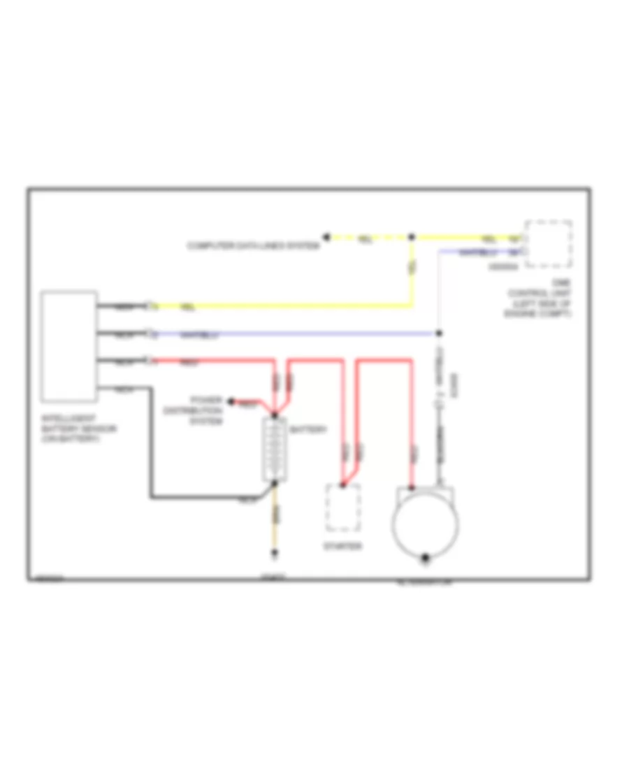
STARTING/CHARGING
Charging Wiring Diagram for MINI Cooper Paceman S ALL4 2014
List of elements for Charging Wiring Diagram for MINI Cooper Paceman S ALL4 2014:
- Alternator
- Battery
- Computer data lines system
- Dme control unit (left side of engine compt)
- Intelligent battery sensor (on battery)
- Nca
- Power distribution system
- Red
- Starter
- X2498
- X60004
- X6402
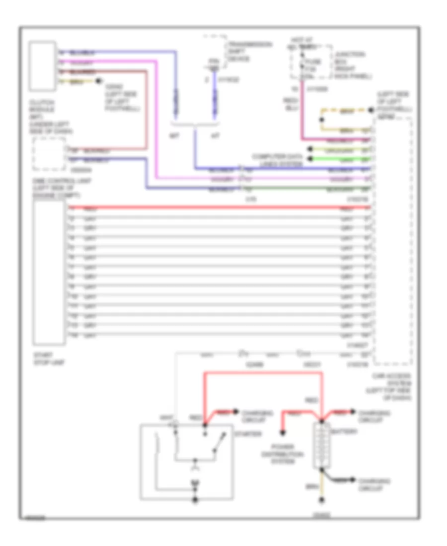
Starting Wiring Diagram for MINI Cooper Paceman S ALL4 2014
List of elements for Starting Wiring Diagram for MINI Cooper Paceman S ALL4 2014:
- (left side of left footwell) x2042
- A/t
- Battery
- Car access system (left top side of dash)
- Charging circuit
- Clutch module (m/t) (under left side of dash)
- Computer data lines system
- Dme control unit (left side of engine compt)
- Fuse f36 5a
- Hot at all times
- Junction box (right kick panel)
- M/t
- Nca
- P/n sig
- Power distribution system
- Red
- Start stop unit
- Starter
- Transmission shift device
- X10318
- X11006
- X11632
- X14027
- X15
- X2042 (left side of left footwell)
- X2498
- X60004
- X6402
- X9331
SUPPLEMENTAL RESTRAINTS
Supplemental Restraints Wiring Diagram (1 of 2) for MINI Cooper Paceman S ALL4 2014
List of elements for Supplemental Restraints Wiring Diagram (1 of 2) for MINI Cooper Paceman S ALL4 2014:
- (base of driver "b" pillar ) driver belt force limiter alternator
- (base of driver's front seat belt buckle assembly) driver's seat belt tensioner generator
- (base of passenger's front seat belt buckle assembly) passenger's seat belt tensioner generator
- (front of driver's door) driver's side door air bag sensor
- (front of left front wheel) driver's side front air bag sensor
- (in steering wheel) driver side air bag inflator assembly
- (top right side of dash) passenger side air bag inflator assembly
- (under left center side headliner) driver's side head air bag inflator assembly
- (under right center side headliner) passenger's side head air bag inflator assembly
- Deactivate ind
- Driver's side seat belt retractor tensioner (base of driver's "b" pillar)
- Drvr alt +
- Drvr alt -
- Drvr seat belt
- Drvr seat belt +
- Drvr seat belt -
- Drvr seat sens
- Drvr side +
- Drvr side -
- Front passenger belt force limiter alternator (base of front passenger "b" pillar)
- Front passenger's side door air bag sensor (front of passenger's door)
- Frt pass sens
- Ground
- L b-pillar sens
- Left head +
- Left head -
- Lf door sens
- Lf sens
- Multiple restraint system control unit (center console)
- Nca
- Occupancy sig
- Pass alt +
- Pass alt -
- Pass seat belt
- Pass seat belt +
- Pass seat belt -
- Pass side +
- Pass side -
- Passenger's side "b" pillar air bag sensor (behind right rear trim panel)
- Passenger's side front air bag sensor (front of right front wheel)
- Passenger's side seat belt retractor tensioner alternator (base of passenger's "b" pillar)
- R b-pillar sens
- Rf door sens
- Rf sens
- Right head +
- Right head -
- Terminal r
- X18069
- X256
- X257
- X275
- X279
- X46 (under center console)
Supplemental Restraints Wiring Diagram (2 of 2) for MINI Cooper Paceman S ALL4 2014
List of elements for Supplemental Restraints Wiring Diagram (2 of 2) for MINI Cooper Paceman S ALL4 2014:
- (in driver's seat belt buckle assembly) driver's seat belt buckle contact
- (in passenger's seat belt buckle assembly) passenger's seat belt buckle contact
- (on right seat rail) driver seat position sensor
- (under front passenger seat) front passenger seat position sensor
- Can h
- Can l
- Car access system (left top side of dash)
- Clster air bag +
- Clster air bag -
- Computer data lines system
- Driver's air bag inflator assembly (in steering wheel)
- Driver's side "b" pillar air bag sensor (behind left rear trim panel)
- Fuse f51 40a
- Hot at all times
- Junction box (right kick panel)
- Multiple restraint system control unit (center console)
- Nca
- Pass air bag +
- Pass air bag -
- Pass knee +
- Pass knee -
- Passenger's air bag inflator assembly (top right side of dash)
- Passenger's knee air bag inflator assembly
- Passenger's seat occupancy detector (in front passenger's seat cushion)
- Red
- Roof operating unit
- Steering column switch cluster
- X01001
- X01071
- X01072
- X10179
- X10318
- X11006
- X14286
- X15
- X18325
- X275
- X279
- X46 (under center console)
TRANSMISSION
Transmission Wiring Diagram (1 of 2) for MINI Cooper Paceman S ALL4 2014
List of elements for Transmission Wiring Diagram (1 of 2) for MINI Cooper Paceman S ALL4 2014:
- Car access system (left top side of dash)
- Computer data lines system
- Fuse f15 15a
- Fuse f19 5a
- Fuse f26 5a
- Hot at all times
- Hot w/ terminal 30g relay energized
- Junction box (right kick panel)
- Red
- Transmission control module (under left side of dash)
- Transmission shift device
- X10318
- X11003
- X11008
- X11630
- X11631
- X11632
- X11633
- X11634
- X15
- X175 (left front side of engine compt)
- X2846 (right side of right footwell, under door)
Transmission Wiring Diagram (2 of 2) for MINI Cooper Paceman S ALL4 2014
List of elements for Transmission Wiring Diagram (2 of 2) for MINI Cooper Paceman S ALL4 2014:
- (right side of right footwell, under door) x2846
- All-wheel drive vehicle clutch (on rear of transaxle)
- Computer data lines system
- Dynamic stability control (dsc) (left rear of engine compt)
- Gear indicator lighting
- Interior lights system
- Left rocker switch
- Nca
- Red
- Right rocker switch
- Selector lever position switch (at base of gear selector)
- Steering column switch cluster
- X01006
- X01185
- X0465
- X13795 (behind left rear trim panel)
- X15
- X1880
TRUNK, TAILGATE, FUEL DOOR
Trunk & Fuel Door Release Wiring Diagram for MINI Cooper Paceman S ALL4 2014
List of elements for Trunk & Fuel Door Release Wiring Diagram for MINI Cooper Paceman S ALL4 2014:
- (behind right rear trim panel) x490
- (right side of right footwell, under door) x2846
- Computer data lines system
- Exterior trunk lid button
- Fuel filler flap central locking drive (left side of rear compt)
- Fuse box (right rear of engine compt)
- Fuse f60 125a
- Hot at all times
- Junction box (right kick panel)
- Junction box electronics
- Lights system interior
- Red
- Trunk lid central locking drive (center rear of trunk)
- X11002
- X11010
- X14272
- X18090
- X34117
- X490 (behind right rear trim panel)
WARNING SYSTEMS
Warning Systems Wiring Diagram for MINI Cooper Paceman S ALL4 2014
List of elements for Warning Systems Wiring Diagram for MINI Cooper Paceman S ALL4 2014:
- Computer data lines system
- Fuse f19 5a
- Hot w/ terminal 30g relay energized
- Junction box (right kick panel)
- Power distribution system
- Red
- Tire pressure control (rdc) (right side of luggage compt)
- X11008
- X490 (behind right rear trim panel)
WIPER/WASHER
Front & Rear Wiper/Washer Wiring Diagram for MINI Cooper Paceman S ALL4 2014
List of elements for Front & Rear Wiper/Washer Wiring Diagram for MINI Cooper Paceman S ALL4 2014:
- (behind right side of front bumper)
- (left side of engine compt) front power distribution box
- (right kick panel) junction box
- Additional instrument
- Clubman
- Computer data lines system
- Electronics junction box
- Front washer pump relay
- Fuse box (right rear of engine compt)
- Fuse f09 30a
- Fuse f19 5a
- Fuse f25 15a
- Fuse f50 15a
- Fuse f60 125a
- Hot at all times
- Hot w/ terminal 30g relay energized
- Outside temperature sensor
- Rain/ headlight sensor
- Rear washer pump relay
- Rear window wiper relay
- Rear wiper drive
- Red
- Right rear trim panel)
- Steering column & switch cluster
- Washer fluid level switch (front of left front wheel)
- Windshield washer pump (front of left front wheel)
- Wiper module
- Wiper relay
- Wiper switch
- X10669
- X11002
- X11007
- X11008
- X11010
- X14272
- X15
- X175 (left front side of engine compt)
- X18090
- X1880
- X2184 (under driver's seat)
- X34117
- X4009
- X4010
- X4013
- X490 (behind
Headlamp Washer Wiring Diagram for MINI Cooper Paceman S ALL4 2014
List of elements for Headlamp Washer Wiring Diagram for MINI Cooper Paceman S ALL4 2014:
- Fuse f2 30a
- Headlight cleaning system relay
- Headlight washer pump (left front wheelwell)
- Hot at all times
- Junction box (right kick panel)
- X11001
- X175 (left front side of engine compt)
Washer Jet Heater Wiring Diagram for MINI Cooper Paceman S ALL4 2014
List of elements for Washer Jet Heater Wiring Diagram for MINI Cooper Paceman S ALL4 2014:
- Driver's side heated washer nozzle
- Driver's side outside mirror
- Electronics junction box
- Fuse box (right rear of engine compt)
- Fuse f60 125a
- Hot at all times
- Junction box (right kick panel)
- Nca
- Passenger's side heated washer nozzle
- Passenger's side outside mirror
- Red
- X11002
- X175 (left front side of engine compt)
- X18090
- X256
- X257
- X34117