Diagram sections — 29 (59 total)
AIR CONDITIONING ANTI-LOCK BRAKES ANTI-THEFT BODY CONTROL MODULES COMPUTER DATA LINES COOLING FAN CRUISE CONTROL DEFOGGERS ELECTRONIC POWER STEERING ENGINE PERFORMANCE EXTERIOR LIGHTS GROUND DISTRIBUTION HEADLIGHTS HORN INSTRUMENT CLUSTER INTERIOR LIGHTS NAVIGATION POWER DISTRIBUTION POWER MIRRORS POWER SEATS POWER TOP/SUNROOF POWER WINDOWS RADIO SHIFT INTERLOCK STARTING/CHARGING SUPPLEMENTAL RESTRAINTS TRANSMISSION TRUNK, TAILGATE, FUEL DOOR WIPER/WASHER
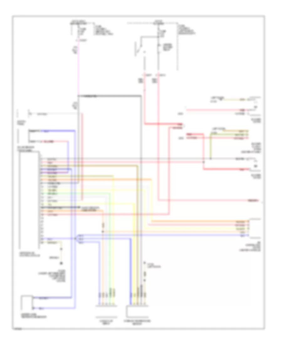
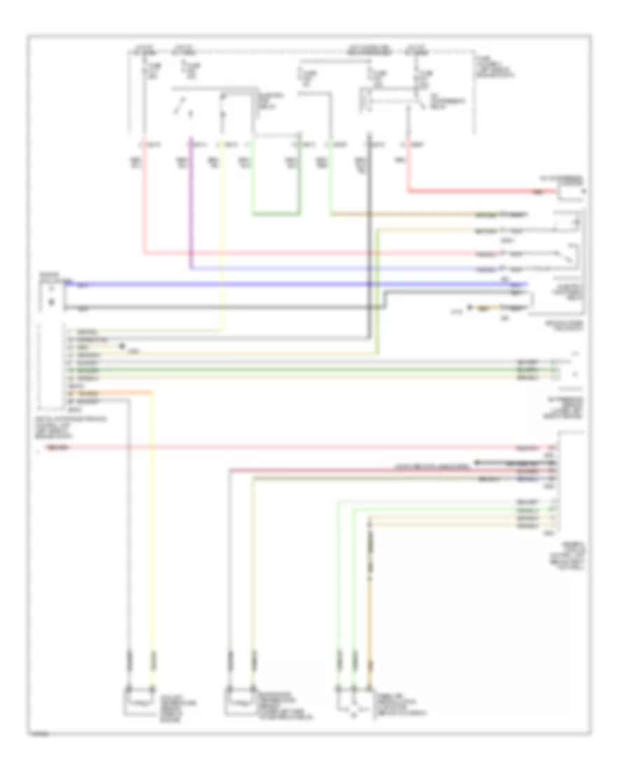
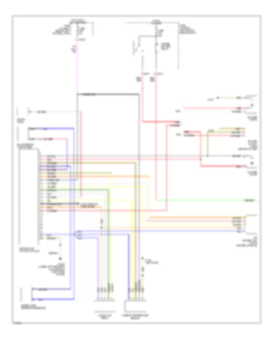
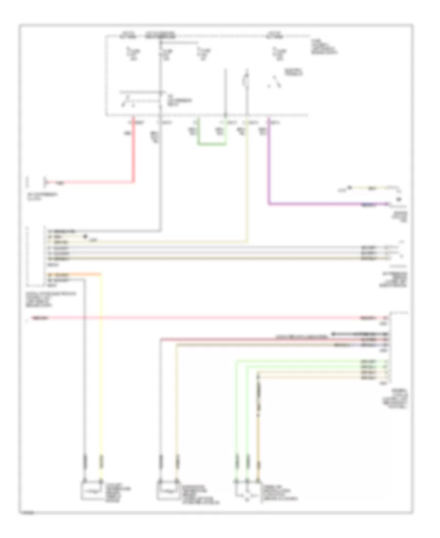
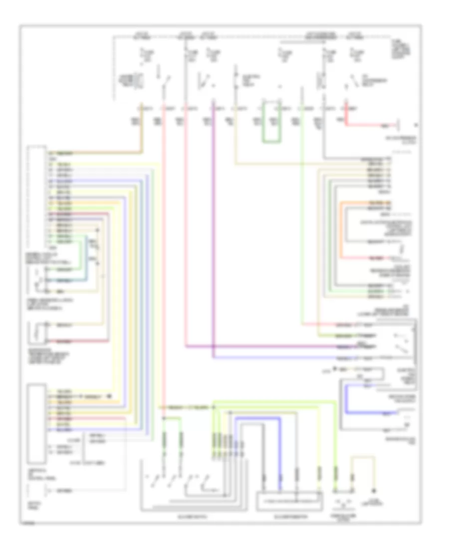
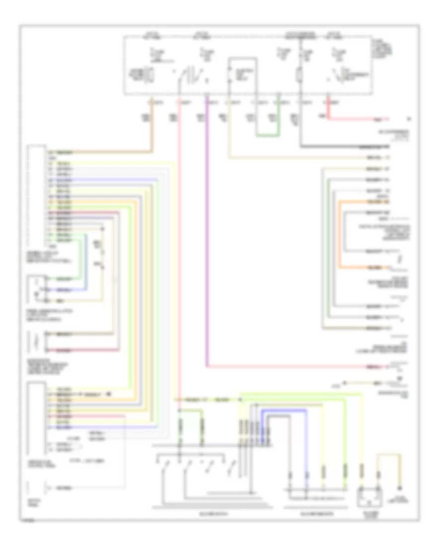
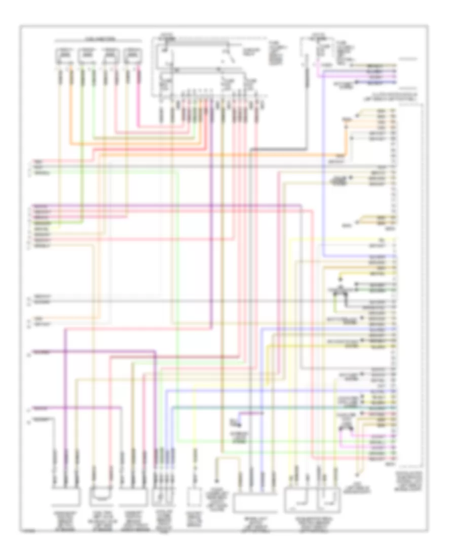
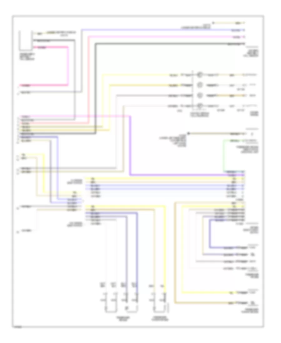
AIR CONDITIONING Automatic A/C Wiring Diagram, with Dual Stage Cooling Fans (1 of 2) for MINI Cooper S 2003 List of elements for Automatic A/C Wiring Diagram, with Dual Stage Cooling Fans (1 of 2) for MINI Cooper S 2003: 29 (center of dash) (left door) (top of dash) Air distribution motor (center console) Blower motor Blower output stage Computer data lines system Fuse f29 5a Fuse fl9 30a Fuse holder 2 (behind left footwell trim) Fuse holder 3 (left side of engine compt) Heater blower relay Heater core temperature sensor Heating & a/c control module Hot at all times Hot in accy, run and start Interior temperature sensor Mixing flap servo Nca Red Red red Solar sensor Switch panel X10207 X1108 X1108 (left door) X13230 (under left rear seat) (convertible) (left door) (coupe) X4007 X4013 Automatic A/C Wiring Diagram, with Dual Stage Cooling Fans (2 of 2) for MINI Cooper S 2003 List of elements for Automatic A/C Wiring Diagram, with Dual Stage Cooling Fans (2 of 2) for MINI Cooper S 2003: 38 A/c compressor clutch A/c compressor relay A/c pressure sensor (lower left side of engine) Computer data lines system Coolant temperature sensor (rear of engine) Digital motor electronics control unit (left side of engine compt) Electric fan relay Electric fan stage 2 relay Engine cooling fan Evaporator temperature sensor (under left side of center console) Fresh air/ recirculation flap motor (behind glove box) Fuse f03 15a Fuse f05 5a Fuse f07 30a Fuse f08 30a Fuse fl11 50a Fuse holder 3 (left side of engine compt) General module control unit (behind right footwell) Hot at all times Hot w/ dme main relay energized Nca Red Second stage fan switch X167 X175 X253 X254 X255 X4009 X4010 X4013 X4014 X4015 X53 X5301 X6000 X60004 X8687 Automatic A/C Wiring Diagram, with Single Stage Cooling Fans (1 of 2) for MINI Cooper S 2003 List of elements for Automatic A/C Wiring Diagram, with Single Stage Cooling Fans (1 of 2) for MINI Cooper S 2003: 25 Air distribution motor (center console) Blower motor Blower output stage (center of dash) Computer data lines system Fuse f29 5a Fuse fl9 30a Fuse holder 2 (behind left footwell trim) Fuse holder 3 (left side of engine compt) Heater blower relay Heater core temperature sensor Heating & a/c control module Hot at all times Hot in accy, run and start Interior temperature sensor Mixing flap servo Nca Red Solar sensor (top of dash) Switch panel X10207 X1108 X1108 (left door) X13230 (under left rear seat) (convertible) (left door) (coupe) X4007 X4013 Automatic A/C Wiring Diagram, with Single Stage Cooling Fans (2 of 2) for MINI Cooper S 2003 List of elements for Automatic A/C Wiring Diagram, with Single Stage Cooling Fans (2 of 2) for MINI Cooper S 2003: 30 A/c compressor clutch A/c compressor relay A/c pressure sensor (lower left side of engine) Computer data lines system Coolant temperature sensor (rear of engine) Digital motor electronics control unit (left side of engine compt) Electric fan relay Engine cooling fan Evaporator temperature sensor (under left side of center console) Fresh air/ recirculation flap motor (behind glove box) Fuse f03 15a Fuse f05 5a Fuse f07 30a Fuse f08 20a Fuse holder 3 (left side of engine compt) General module control unit (behind right footwell) Hot at all times Hot w/ dme main relay energized Red X167 X175 X253 X254 X255 X4010 X4013 X4014 X6000 X60004 X8687 Manual A/C Wiring Diagram, with Dual Stage Cooling Fans for MINI Cooper S 2003 List of elements for Manual A/C Wiring Diagram, with Dual Stage Cooling Fans for MINI Cooper S 2003: 48 (left door) (not used) A/c compressor clutch A/c compressor relay A/c pressure sensor (lower left side of engine) Blower resistor Blower switch Coolant temperature sensor (rear of engine) Digital motor electronics control unit (left side of engine compt) Electric fan relay Electric fan stage 2 relay Engine cooling fan Evaporator temperature sensor (under left side of center console) Fresh air/recirculation flap motor (behind glove box) Fuse f03 15a Fuse f05 5a Fuse f07 30a Fuse f08 30a Fuse fl11 50a Fuse fl9 30a Fuse holder 3 (left side of engine compt) General module control unit (behind right footwell) Heater blower relay Heating & a/c control panel Hot at all times Hot w/ dme main relay energized Nca Rear blower motor Red Second stage fan switch Switch panel W/ ihkr W/ ihs X1108 X175 X253 X255 X4007 X4009 X4010 X4013 X4014 X4015 X53 X5301 X6000 X60004 X8687 Manual A/C Wiring Diagram, with Single Stage Cooling Fans for MINI Cooper S 2003 List of elements for Manual A/C Wiring Diagram, with Single Stage Cooling Fans for MINI Cooper S 2003: 40 (left door) (not used) A/c compressor clutch A/c compressor relay A/c pressure sensor (lower left side of engine) Blower motor Blower resistor Blower switch Coolant temperature sensor (rear of engine) Digital motor electronics control unit (left side of engine compt) Electric fan relay Engine cooling fan Evaporator temperature sensor (under left side of center console) Fresh air/recirculation flap motor (behind glove box) Fuse f03 15a Fuse f05 5a Fuse f07 30a Fuse f08 20a Fuse fl9 30a Fuse holder 3 (left side of engine compt) General module control unit (behind right footwell) Heater blower relay Heating & a/c control panel Hot at all times Hot w/ dme main relay energized Red Switch panel W/ ihkr W/ ihs X1108 X175 X253 X255 X4007 X4010 X4013 X4014 X6000 X60004 X8687
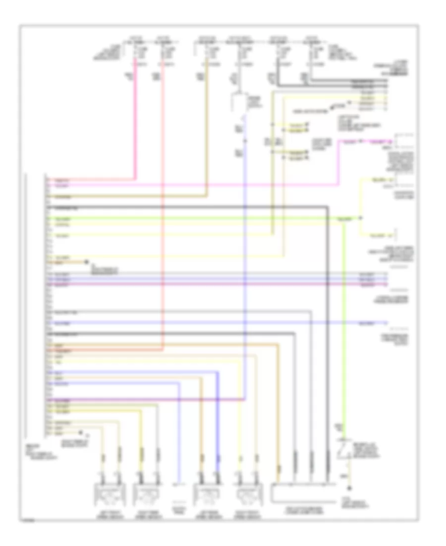
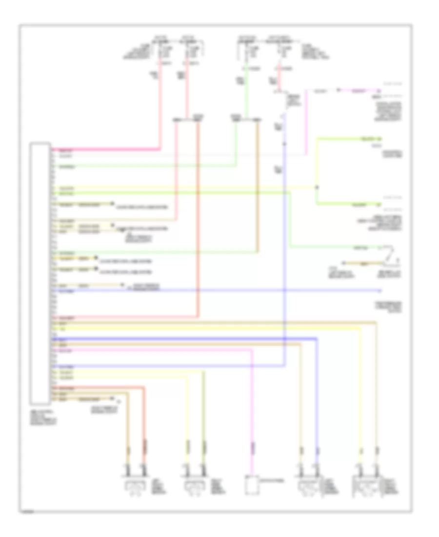
ANTI-LOCK BRAKES Anti-lock Brakes Wiring Diagram, with Dynamic Stability Control for MINI Cooper S 2003 List of elements for Anti-lock Brakes Wiring Diagram, with Dynamic Stability Control for MINI Cooper S 2003: 42 (left door) (coupe) (under left rear seat) (convertible) (lower steering column) steering angle sensor (right rear of engine compt) Abs/dsc unit (right rear of Brake fluid level switch (left side of engine compt) Brake light switch Computer data lines system Digital motor electronics control unit (left side of engine compt) Dsc motion sensor (under lever cover) Engine compt) Fuse f06 30a Fuse f2 5a Fuse f33 10a Fuse f40 5a Fuse f6 5a Fuse fl6 40a Fuse holder 2 (behind left footwell trim) Fuse holder 3 (left side of engine compt) Headlight beam height control module (behind right side of glove box) Headlights system Hot at all times Hot in accy, run and start Hot in on or start Hydraulic brake pressure sensor Left front speed sensor Left rear speed sensor Navigation computer Nca Right front speed sensor Right rear speed sensor Switch panel Tire pressure warning (rdm) switch X10200 X10205 X10207 X1314 X13230 X175 (left side of engine compt) X4 (right rear of engine compt) X4010 X4013 X6004 Anti-lock Brakes Wiring Diagram, without Dynamic Stability Control for MINI Cooper S 2003 List of elements for Anti-lock Brakes Wiring Diagram, without Dynamic Stability Control for MINI Cooper S 2003: 35 (2002 & 2003) (2004) (right rear of engine compt) 2002& Abs control module (right rear of engine compt) Brake fluid level switch Brake light switch Computer data lines system Digital motor electronics control unit (left side of engine compt) Fuse f06 30a Fuse f33 10a Fuse f6 5a Fuse fl6 40a Fuse holder 2 (behind left footwell trim) Fuse holder 3 (left side of engine compt) Headlight beam height control module (behind right side of glove box) Hot at all times Hot in accy, run and start Hot in on or start Left front speed sensor Left rear speed sensor Navigation computer Nca Right front speed sensor Right rear speed sensor Switch panel Tire pressure warning (rdm) switch X10200 X10205 X1314 X175 (left side of engine compt) X4 (right rear of engine compt) X4010 X4013 X6000
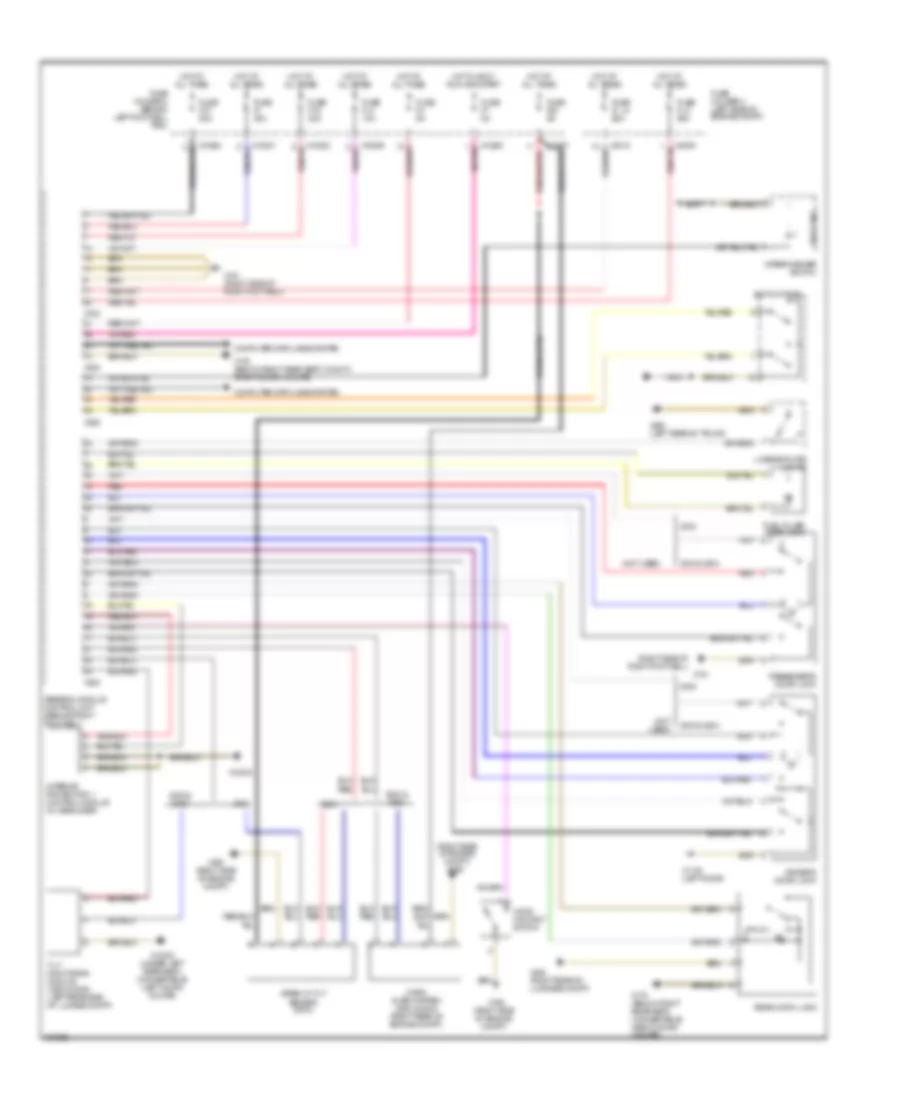
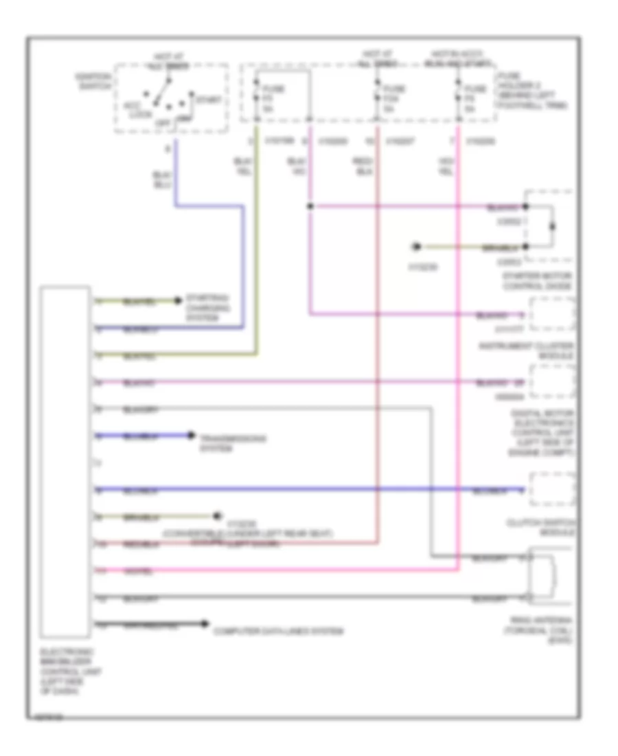
ANTI-THEFT Forced Entry Wiring Diagram for MINI Cooper S 2003 List of elements for Forced Entry Wiring Diagram for MINI Cooper S 2003: 58 (not used) (right side of engine compt) (right side of engine compt) x165 (right side of right footwell) 2002 & 2003 & 2004 Computer data lines system Driver's door lock Fuel filler door lock Fuse f1 30a Fuse f14 10a Fuse f19 30a Fuse f24 5a Fuse f37 20a Fuse f4 5a Fuse f7 5a Fuse fl 12 50a Fuse fl 8 50a Fuse holder 2 (behind left footwell trim) Fuse holder 3 (left side of engine compt) General module control unit (behind right footwell) Hood contact switch Horn alarm system (2002 & 2003) (right rear of engine compt) Hot at all times Hot in accy, run and start Interior protection 1 control module (in headliner) License plate lights Nca Passenger's door lock Rear hatch lock Red Siren w/ tilt sensor (2004) Switch panel Theft ind Tilt monitoring module (2002 & 2003) (left rear side of lugage compt) Wiper/washer switch X10200 X10201 X10202 X10206 X10207 X1108 (left door) X13230 X13230 (under left rear seat) (convertible) (left door) (coupe) X151 X151 (right side of right footwell) X165 X165 (right side of engine compt) X179 (below right rear seat) (convertible) (right door) (coupe) X179 (below right rear seat) (convt) (right door) (coupe) X253 X254 X255 X332 X4009 X4010 X490 (left rear of trunk) X494 (right rear of luggage compt) Immobilizer Wiring Diagram for MINI Cooper S 2003 List of elements for Immobilizer Wiring Diagram for MINI Cooper S 2003: 28 Acc lock Clutch switch module Computer data lines system Digital motor electronics control unit (left side of engine compt) Electronic immobilizer control unit (left side of dash) Fuse f24 5a Fuse f5 5a Fuse f6 5a Fuse holder 2 (behind left footwell trim) Hot at all times Hot in accy, run and start Ignition switch Instrument cluster module Off Ring antenna (toroidal coil) (ews) Start Starter motor control diode Starting/ charging system Transmissions system X10199 X10200 X10207 X11177 X13230 X13230 (convertible) (under left rear seat) (coupe) (left door) X3552 X3553 X60004
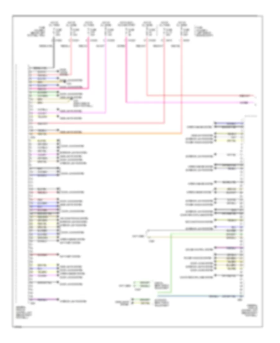
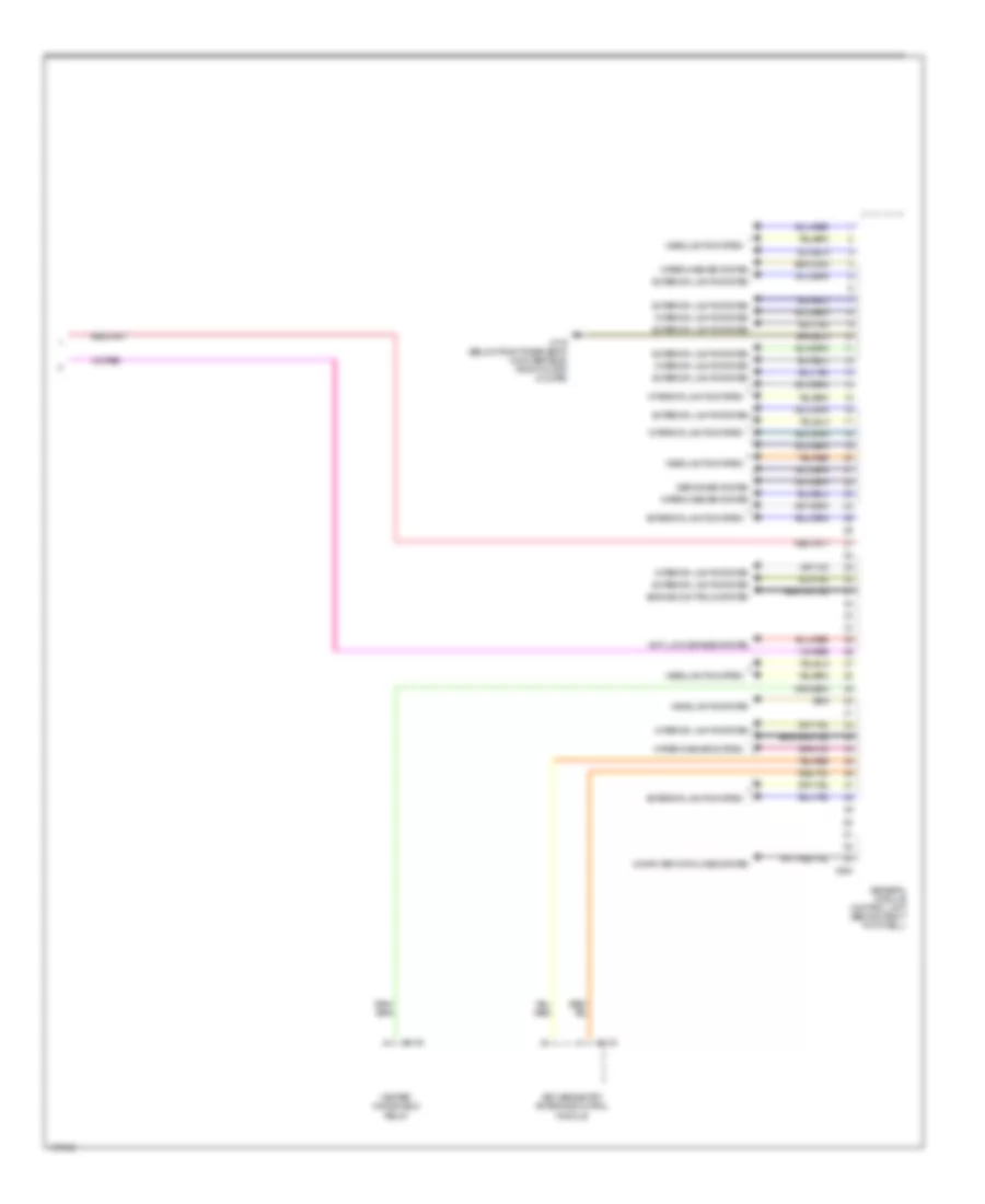
BODY CONTROL MODULES Body Control Modules Wiring Diagram (1 of 2) for MINI Cooper S 2003 List of elements for Body Control Modules Wiring Diagram (1 of 2) for MINI Cooper S 2003: 39 (not used) Air conditioning system Anti-theft system Automatic beam throw adjustment Computer data lines system Cruise control system Door locks system Exterior lights system Fuse f1 30a Fuse f14 10a Fuse f19 30a Fuse f37 20a Fuse f4 5a Fuse f7 5a Fuse fl 12 50a Fuse fl 8 50a Fuse holder 2 (behind left footwell trim) Fuse holder 3 (left side of engine compt) General module control unit (behind right footwell) Headlights system Hot at all times Hot in accy, run and start Interior lights system Manual beam throw adjustment Power windows system Red Wiper/washer system X10200 X10201 X10202 X10206 X151 X151 (right side of right footwell) X1527 X253 X255 X332 X4009 X4010 Body Control Modules Wiring Diagram (2 of 2) for MINI Cooper S 2003 List of elements for Body Control Modules Wiring Diagram (2 of 2) for MINI Cooper S 2003: 15 Anti-lock brakes system Computer data lines system Defogger system Engine controls system Exterior lights system General module control unit (behind right footwell) Headlights system Heated windshield relay Interior lights system Keyless entry antenna/control module Wiper/washer system X1143 X179 (below right rear seat) (convertible) (right door) (coupe) X254 X3148
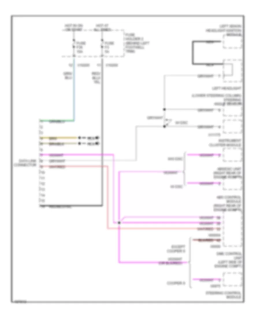
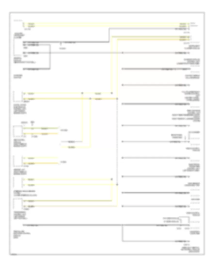
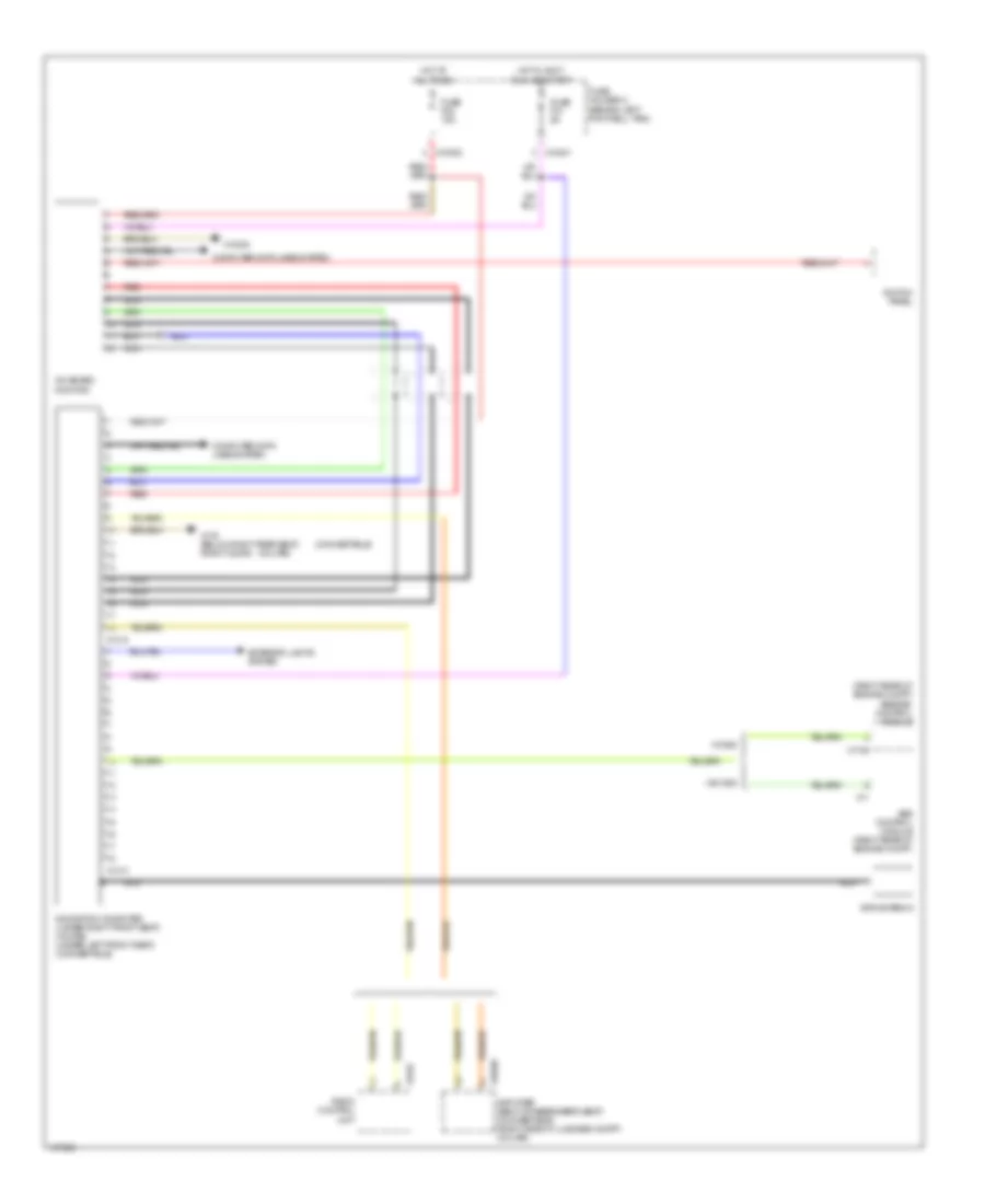
COMPUTER DATA LINES Data Link Connector Wiring Diagram for MINI Cooper S 2003 List of elements for Data Link Connector Wiring Diagram for MINI Cooper S 2003: 26 (lower steering column) steering angle sensor Abs control module (right rear of engine compt) Abs/dsc unit (right rear of engine compt) Connector Cooper s Data link Dme control unit (left side of engine compt) Except cooper s Fuse f3 5a Fuse f36 10a Fuse holder 2 (behind left footwell trim) Hot at all times Hot in on or start Instrument cluster module Left headlight Left xenon headlight ignition module Nca Steering control module W/ dsc W/o dsc X10200 X10205 X11175 X6000 X60004 X6975 High/Low Bus Wiring Diagram for MINI Cooper S 2003 List of elements for High/Low Bus Wiring Diagram for MINI Cooper S 2003: 46 2002-03 Abs control module (right rear of engine compt) Abs/dsc unit (right rear of engine compt) Amplifier Auxiliary Boost radio Cd changer Cluster Contact spring (volute spring) Digital motor electronics control unit (left side of engine compt) Electronic immobilizer control unit (left side of dash) General module (behind right footwell) Headlight vertical aim control module (2002 & 2003) Instrument Instrument cluster module Multiple restraint system control unit (center tunnel, under carpet) Navigation computer Nca On-board monitor Park distance control unit (right rear passenger compt) (convt) right rear of luggage compt) (coupe) Radio control module Rain sensor (windshield top) Steering angle sensor (w/ dsc) (lower steering column) Sunroof module control unit (under front headliner) Tire failure indicator control module (2002) Transmission control unit (left side of left footwell) Video control module W/ dsc W/ ihka W/ video module W/o dsc W/o video module Wave radio X11 X11175 X11176 X11177 X11525 X1312 X1314 X1746 X18114 X19561 X254 X255 X60004
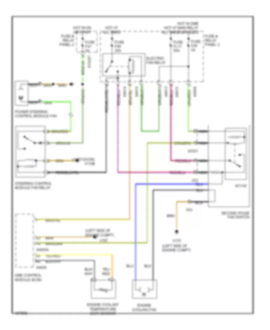
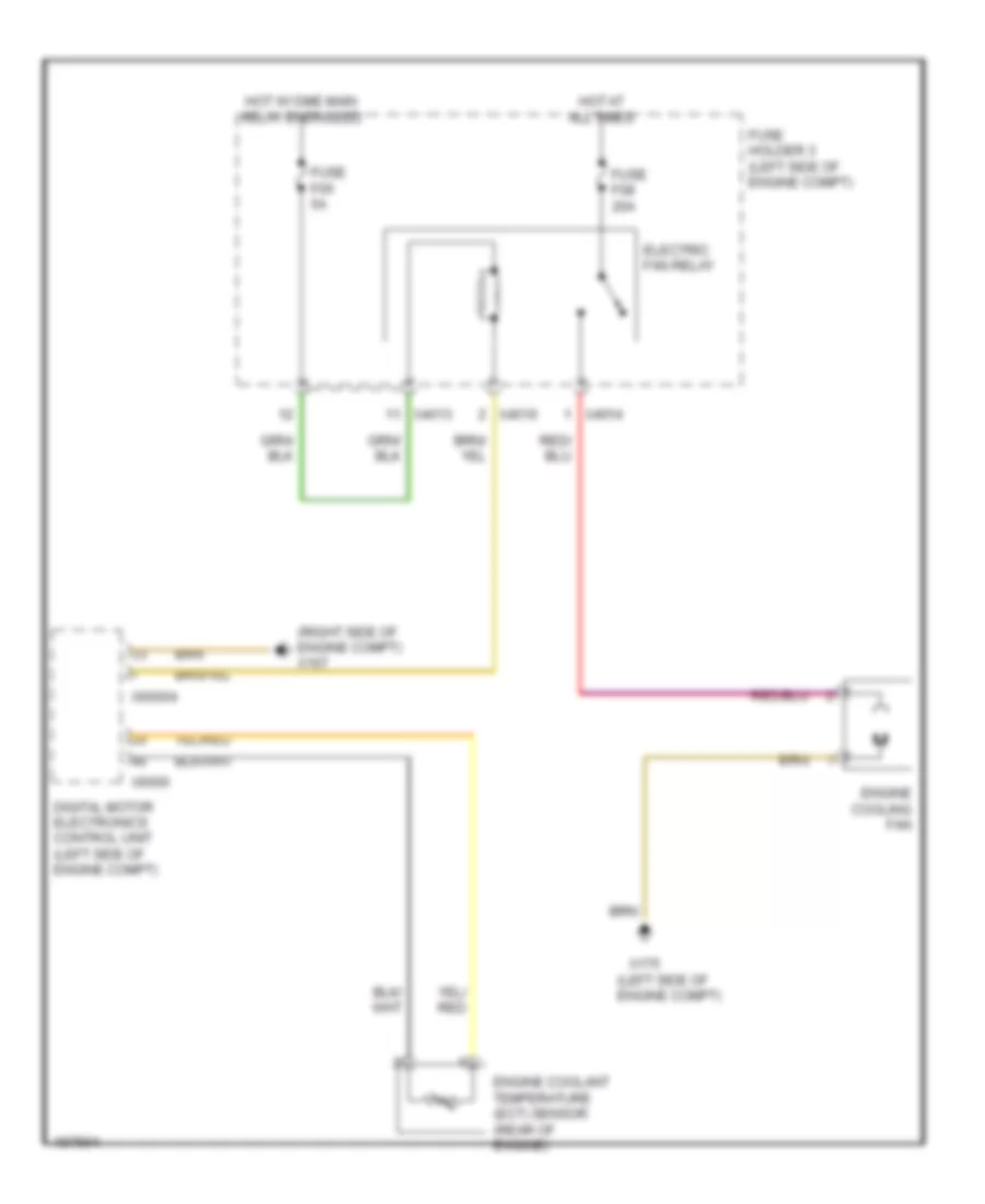
COOLING FAN Cooling Fan Wiring Diagram, Dual Stage for MINI Cooper S 2003 List of elements for Cooling Fan Wiring Diagram, Dual Stage for MINI Cooper S 2003: 32 (left door) x1108 (left side of engine compt) Dme control module (ecm) Electric fan relay Engine coolant temperature (ect) sensor Engine cooling fan Fuse & relay panel 2 Fuse & relay panel 3 Fuse f05 5a Fuse f08 30a Fuse f41 5a Fuse fl11 50a Hot at all times Hot in on or start Hot w/ dme main relay energized I01135 Nca Power steering control module fan Second stage fan switch Steering control module fan relay X10207 X167 X175 X4009 X4010 X4013 X4014 X4015 X53 X5301 X6000 X60004 Cooling Fan Wiring Diagram, Single Stage for MINI Cooper S 2003 List of elements for Cooling Fan Wiring Diagram, Single Stage for MINI Cooper S 2003: 17 (left side of engine compt) (right side of engine compt) x167 Digital motor electronics control unit (left side of engine compt) Electric fan relay Engine coolant temperature (ect) sensor (rear of engine) Engine cooling fan Fuse f05 5a Fuse f08 20a Fuse holder 3 (left side of engine compt) Hot at all times Hot w/ dme main relay energized X175 X4010 X4013 X4014 X6000 X60004
CRUISE CONTROL Cruise Control Wiring Diagram for MINI Cooper S 2003 List of elements for Cruise Control Wiring Diagram for MINI Cooper S 2003: 32 Abs/dsc unit Accelerator pedal position sensor (below accelerator pedal) Brake light switch Clutch switch module (left side of left footwell) Computer data lines system Contact spring (volute spring) Digital motor electronics control unit (left side of engine compt) Electronic immobilizer (ews) control module Electronic throttle control housing Fuse 10a Fuse 5a Fuse holder 2 (behind left footwell trim) General module (bc1) Hot in accy, run and start Hot in on or start Instrument cluster control module Left mfl switch block Nca Red Right mfl switch block X01000 X01002 X01003 X10195 X10200 X10204 X11177 X13230 X151 X255 X6000 X60004
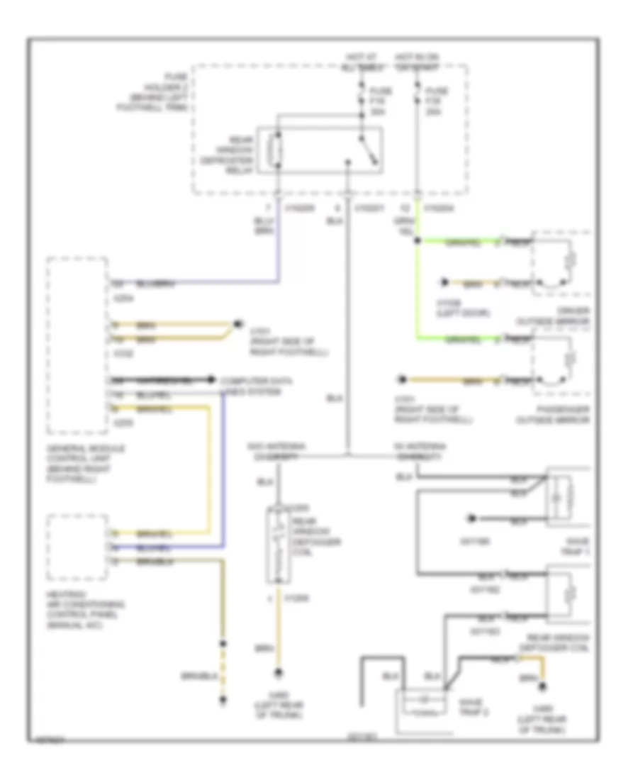
DEFOGGERS Defoggers Wiring Diagram for MINI Cooper S 2003 List of elements for Defoggers Wiring Diagram for MINI Cooper S 2003: 32 Computer data lines system Driver outside mirror Fuse f16 30a Fuse f35 20a Fuse holder 2 (behind left footwell trim) General module control unit (behind right footwell) Heating/ air conditioning control panel (manual a/c) Hot at all times Hot in on or start Nca Passenger outside mirror Rear window defogger coil Rear window defroster relay W/ antenna diversity W/o antenna diversity Wave trap 1 Wave trap 2 X01180 X01181 X01182 X01183 X10201 X10204 X10206 X1108 (left door) X1265 X1266 X151 (right side of right footwell) X254 X255 X332 X490 (left rear of trunk)
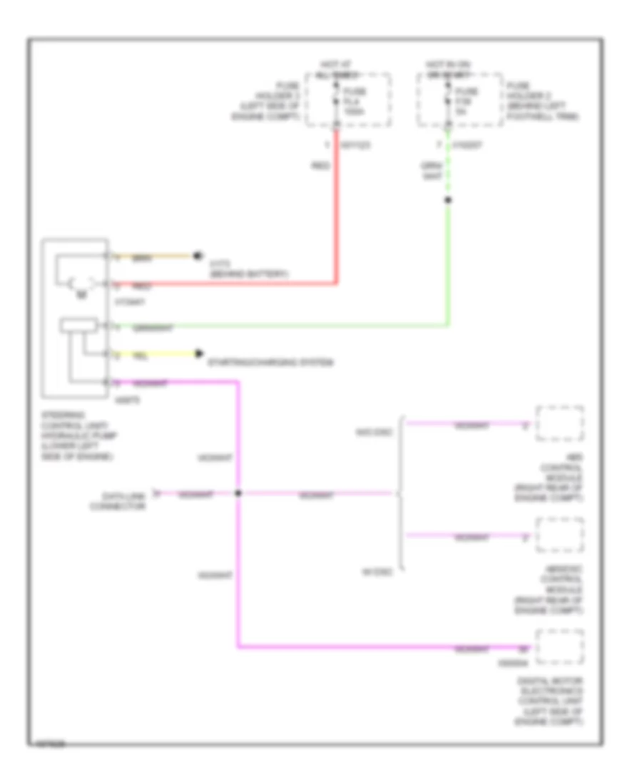
ELECTRONIC POWER STEERING Electronic Power Steering Wiring Diagram for MINI Cooper S 2003 List of elements for Electronic Power Steering Wiring Diagram for MINI Cooper S 2003: 21 Abs control module (right rear of engine compt) Abs/dsc control module (right rear of engine compt) Data link connector Digital motor electronics control unit (left side of engine compt) Fuse f39 5a Fuse fl4 100a Fuse holder 2 (behind left footwell trim) Fuse holder 3 (left side of engine compt) Hot at all times Hot in on or start Red Starting/charging system Steering control unit/ hydraulic pump (lower left side of engine) W/ dsc W/o dsc X01123 X10207 X13441 X173 (behind battery) X60004 X6975
ENGINE PERFORMANCE
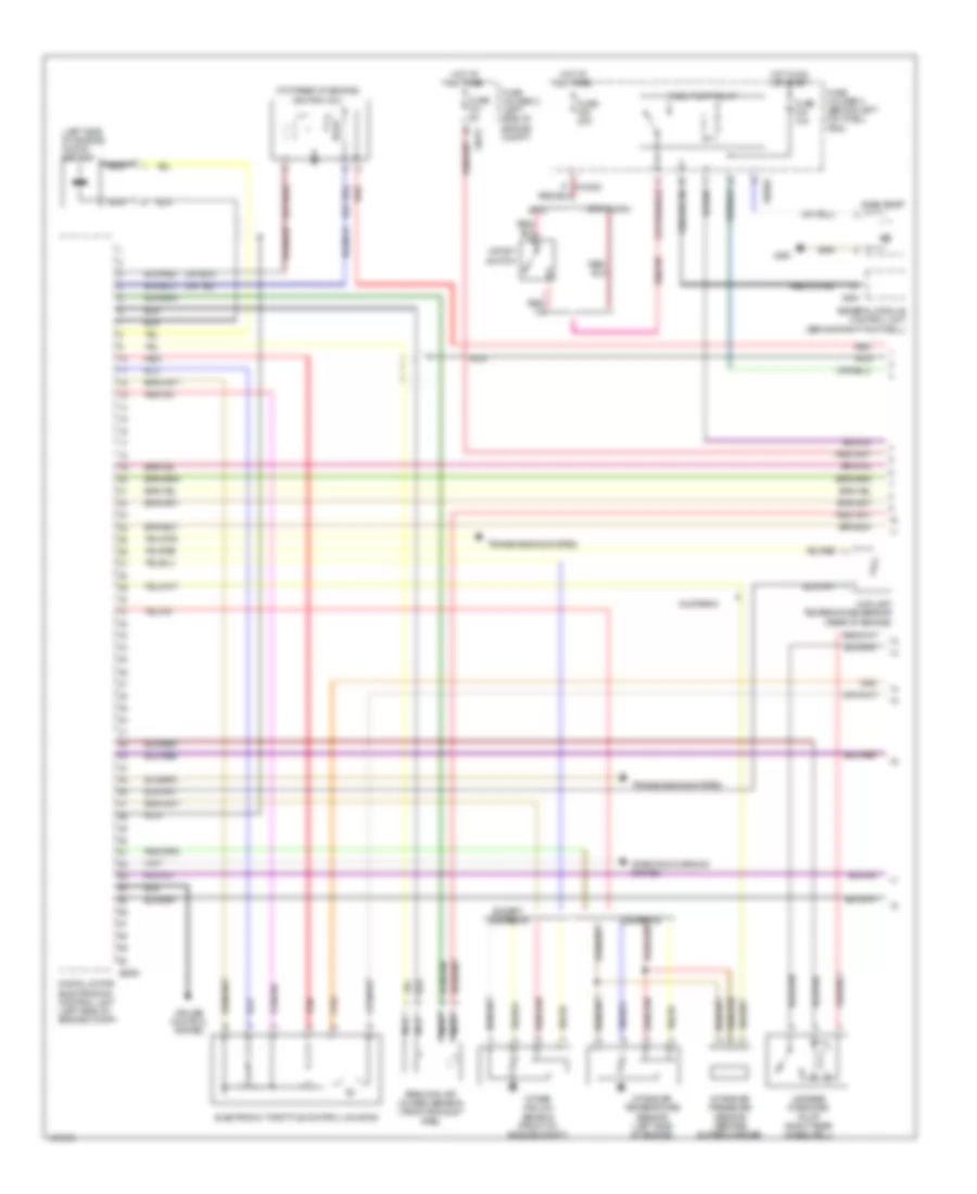
1.6L 1.6L, Engine Performance Wiring Diagram (1 of 2) for MINI Cooper S 2003 List of elements for 1.6L, Engine Performance Wiring Diagram (1 of 2) for MINI Cooper S 2003: 35 (left side of engine) knock sensor (top rear of engine) ignition coil 2003 & 2004 Coolant temperature sensor (rear of engine) Cooper s Cruise control system Digital motor electronics control unit (left side of engine compt) Electronic throttle control housing Except cooper s Fuel pump Fuel pump relay Fuse f01 5a Fuse f20 20a Fuse f34 10a Fuse holder 2 (behind left footwell trim) Fuse holder 3 (left side of engine compt) General module control unit (behind right footwell) Hot at all times Hot in on or start Impact switch Intake air pressure sensor (before supercharger) Intake air temperature sensor (left side of engine) Intake vacuum sensor (front of engine compt) Leakage diagnosis pump (right rear wheelwell) Nca Precatalyst oxygen sensor (front exhaust pipe) Red Starting/charging system Transmissions system X10202 X10204 X254 X4013 X490 X6000 1.6L, Engine Performance Wiring Diagram (2 of 2) for MINI Cooper S 2003 List of elements for 1.6L, Engine Performance Wiring Diagram (2 of 2) for MINI Cooper S 2003: 40 (right front side of engine) Accelerator pedal position sensor (right side of left footwell) Air conditioning system Anti-theft system Brake light switch (left side of left footwell) Camshaft position sensor Catalyst oxygen sensor (front exhaust pipe) Clutch switch module (left side of left footwell) Computer data lines system Contact spring (volute spring) Crankshaft position sensor (bottom of engine) Cruise control system Cyl 1 Cyl 2 Cyl 3 Cyl 4 Digital motor electronics control unit (left side of engine compt) Dme main relay Exterior lights system Fuel injectors Fuel tank vent valve solenoid valve (left side of engine) Fuse f02 20a Fuse f03 15a Fuse f04 15a Fuse f6 5a Fuse holder 2 (behind left footwell trim) Fuse holder 3 (left side of engine compt) Hot at all times Nca Red Shift interlock system X10200 X13230 (under left rear seat) (convt) (left door) (coupe) X167 (left side of engine compt) X4009 X4013 X6000 X6004 X6454 X8687
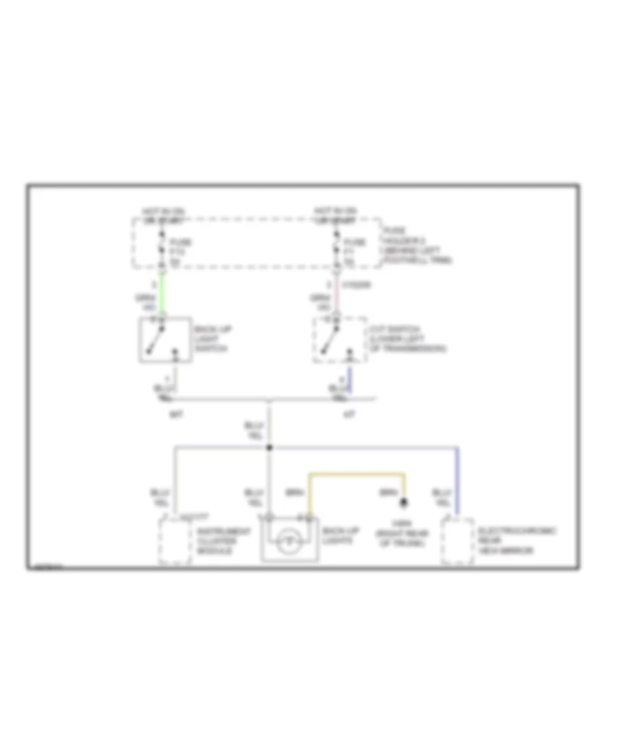
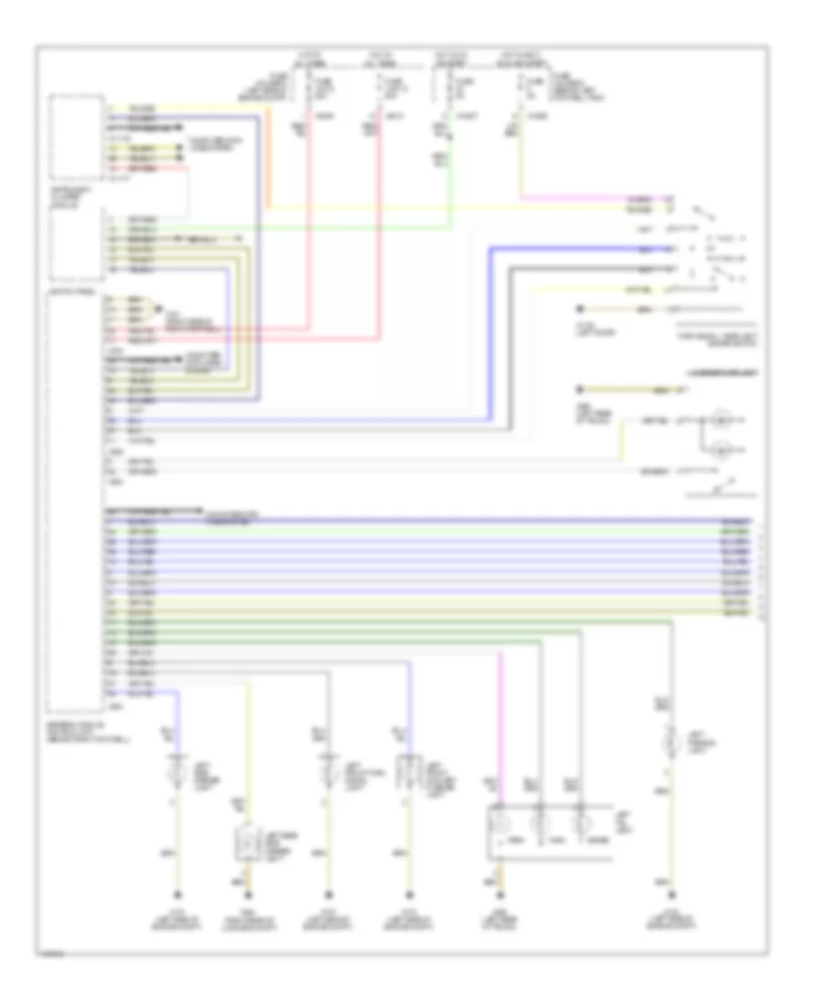
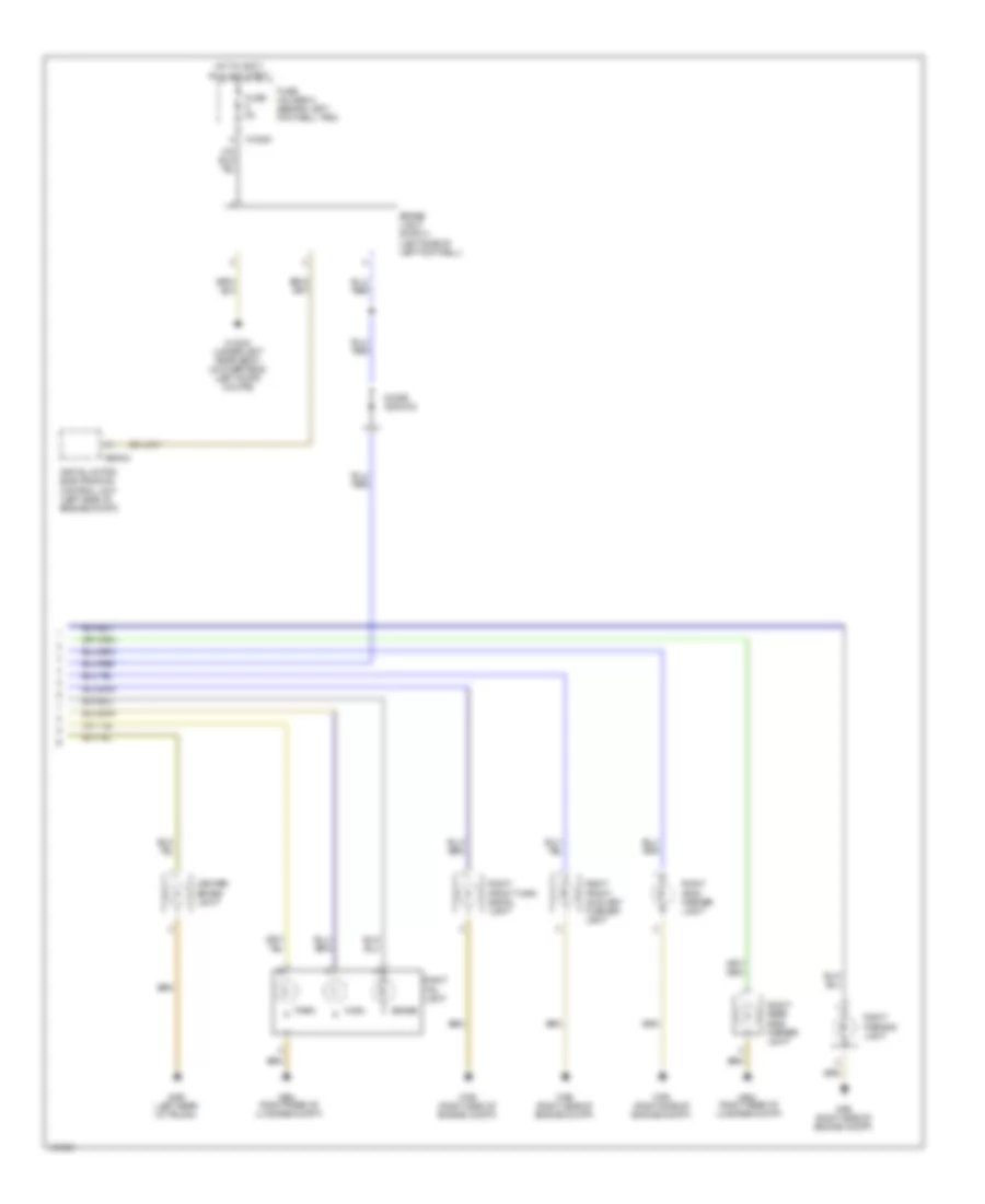
EXTERIOR LIGHTS Back-up Lamps Wiring Diagram for MINI Cooper S 2003 List of elements for Back-up Lamps Wiring Diagram for MINI Cooper S 2003: 14 A/t Back-up light switch Back-up lights Cvt switch (lower left of transmission) Electrochromic rear view mirror Fuse f1 5a Fuse f13 5a Fuse holder 2 (behind left footwell trim) Hot in on or start Instrument cluster module M/t X10206 X11177 X494 (right rear of trunk) Exterior Lamps Wiring Diagram (1 of 2) for MINI Cooper S 2003 List of elements for Exterior Lamps Wiring Diagram (1 of 2) for MINI Cooper S 2003: 39 (right rear of luggage compt) Brake Computer data lines system Fuse 5a Fuse holder 2 (behind left footwell trim) Fuse holder 3 (left side of engine compt) Fuse link 12 50a Fuse link 8 50a General module control unit (behind right footwell) Hot at all times Hot in accy, run and start Hot in on or start Instrument cluster module Left front auxiliary flasher light Left front turn signal light Left parking light Left rear side marker light Left side marker light Left tail light License plate light Park Switch panel Turn Turn signal / headlight dimmer switch X10200 X10207 X1108 (left door) X11175 X11177 X151 (right side of right footwell) X175 (left side of engine compt) X253 X254 X255 X332 X4009 X4010 X490 (left rear of trunk) X494 Exterior Lamps Wiring Diagram (2 of 2) for MINI Cooper S 2003 List of elements for Exterior Lamps Wiring Diagram (2 of 2) for MINI Cooper S 2003: 22 Brake Brake light switch (left side of left footwell) Center brake light Digital motor electronics control unit (left side of engine compt) Diode (2002-03) Fuse 5a Fuse holder 2 (behind left footwell trim) Hot in accy, run and start Park Right front auxiliary flasher light Right front turn signal light Right parking light Right rear side marker light Right side marker light Right tail light Turn X10200 X13230 (under left rear seat) (convertible) (left door) (coupe) X165 (right side of engine compt) X490 (left rear of trunk) X494 (right rear of luggage compt) X60004
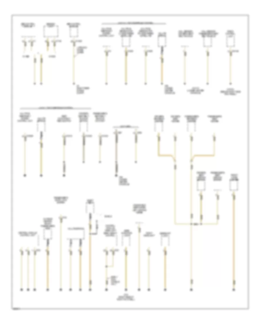
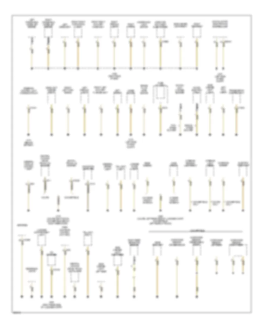
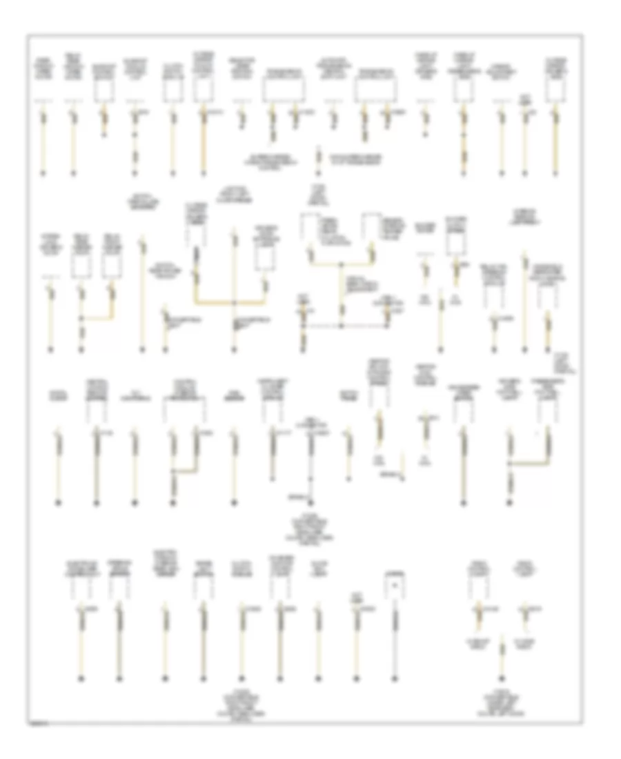
GROUND DISTRIBUTION Ground Distribution Wiring Diagram (1 of 3) for MINI Cooper S 2003 List of elements for Ground Distribution Wiring Diagram (1 of 3) for MINI Cooper S 2003: 42 (w/ multiple restraint system) (w/o multiple restraint system) Abs control module Abs/dsc unit Central module control unit Control module, headlight beam height control Driver's seat belt buckle switch Driver's seat heater Driver's seat heating switch Driver's seatback heater Early models only Eject box Front cigar lighter Gear indicator light Gearshift lock Hall sensor, driver's seat belt buckle Hall sensor, passenger's seat belt buckle Late 2003 model w/ abs Multiple restraint system control unit Multiple sensor for lh side airbag (satellite) Multiple sensor for rh side airbag (satellite) Nca Not used Outside mirror, front passenger's side Passenger's door lock switch Passenger's seat belt buckle contact Passenger's seat heater Passenger's seat heating switch Passenger's seatback heater Radio control unit Right headlight Seat occupancy recognition Shield Volute spring W/ abs W/ dsc Windshield defroster, left heating zone X151 (right side of right footwell) X18170 (under center console) X18723 (behind right side trim panel) X4 (right rear of eng compt) X46 (under center console) Ground Distribution Wiring Diagram (2 of 3) for MINI Cooper S 2003 List of elements for Ground Distribution Wiring Diagram (2 of 3) for MINI Cooper S 2003: 70 Amplifier Brake fluid level switch Cd changer Central locking drive, trunk lid/ tailgate Central locking drive, trunk lid/tailgate Charging socket Convertible Convertible only Coupe Coupe only Digital motor electronics control unit Electric fuel pump Front left auxiliary flasher unit Front left turn signal Front right auxiliary flash unit Front right turn signal lamp Fuse holder iii General brake light General module control unit Headlight washer pump Horn for anti-theft alarm system Interior light, rear Interior reading lamp, front Left fog light Left headlight Left horn Left parking light Left windshield water jet heater License plate light Luggage compartment light Microwave sensor, driver's door Microwave sensor, left rear Microwave sensor, passenger's door Microwave sensor, right rear Motor, electric fan i Navigation computer Nca Park distance control unit (pdc) Rear fog light Rear window Reversing lights Right fog right Right horn Right parking light Right rear brake pad sensor Right windshield water jet heater Side marker light, left Side marker light, left rear Side marker light, right Side marker light, right rear Single- stage blower Steering control unit/ hydraulic pump Switch unit, 2-stage blower Switch, trunk lid contact Taillight, left Taillight, right Transmission control unit Two- stage blower Underhood light switch W/ rear window antenna W/o rear window antenna Wave trap 2 Wiper motor X165 (right side of eng) X167 (left side of eng compt) X173 (behind battery) X175 (left side of eng compt) X179 (coupe: right door, convertible: below right rear door) X490 (coupe: left rear side of luggage compt, convertible: left rear of trunk) X494 (right rear side of luggage compt) Ground Distribution Wiring Diagram (3 of 3) for MINI Cooper S 2003 List of elements for Ground Distribution Wiring Diagram (3 of 3) for MINI Cooper S 2003: 60 Automatic transmission central shift unit Blower motor Blower output stage Brake light switch Central locking remote control Clutch switch module Control module, interior protection Digital clock Diode Driver's door entrance light Driver's side footwell light Electro- chromic interior rear-view mirror Electronic immobilizer control unit Fresh air/air recir- culation flap motor Glove box light Heating & a/c control module Heating/ air con- ditioning control panel Instrument cluster control module Interior reading lamp, front Lighting front left door opener Make-up mirror light, driver's side Make-up mirror light, passenger's side Manual beam throw adjustment Mirror adjustment switch Nca Non-supercharged w/ a/t transmission Not used Obd ii connector On-board monitor control unit Outside mirror fold-in control unit Outside mirror, driver's side Passenger's side footwell light Radio control unit Rain sensor Rear window wiper motor Relay, fan, steering control module Relay, front washer pump Relay, rear washer pump Relay, rear window wiper motor Selector lever position switch Sensor, interior temper- ature Steering angle sensor Sunroof control switch Sunroof module control unit Supercharged w/ egs transmission control Switch panel Switch, rear power window Switch, tire failure indicator System lock, driver's door Tilt monitoring Transmission control unit W/ boost radio W/ ihka W/ wave radio W/o ihka Windscreen wiper switch Windshield defroster, right heating zone X1108 (left door) (partial) X13016 (convertible: under left rear seat, coupe: left door) X13230 (convertible: right front headliner, coupe: headliner) (partial)
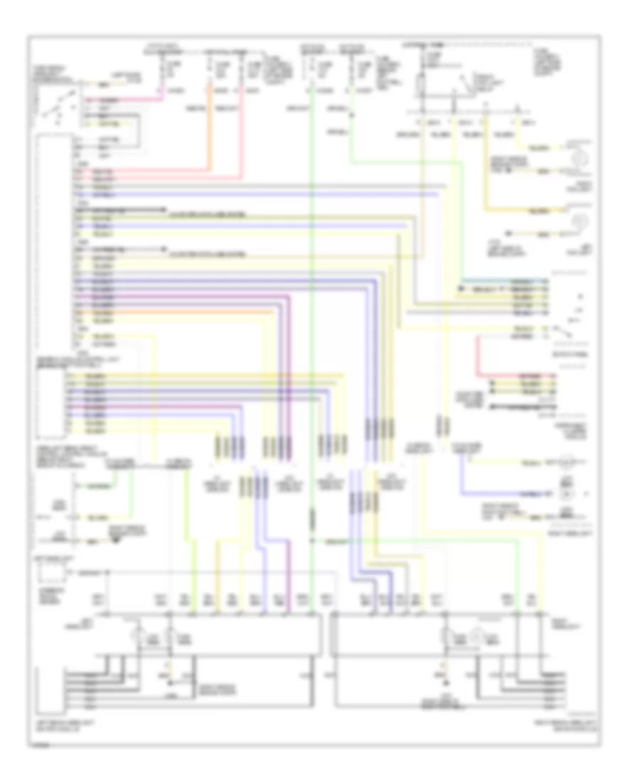
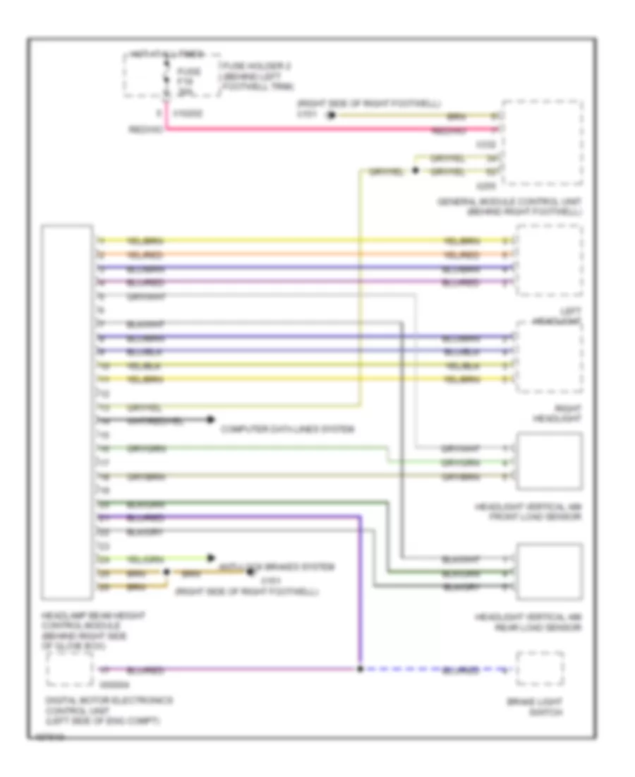
HEADLIGHTS Headlamps Wiring Diagram for MINI Cooper S 2003 List of elements for Headlamps Wiring Diagram for MINI Cooper S 2003: 54 (left door) x1108 (left side of engine compt) (right side of engine compt) (right side of engine compt) x165 (right side of right footwell) (right side of right footwell) x151 Computer data lines system Front fog light relay Fuse f010 15a Fuse f12 5a Fuse f40 5a Fuse f8 5a Fuse fl12 50a Fuse fl8 50a Fuse holder 2 (behind left footwell trim) Fuse holder 3 (left side of engine compt) General module control unit (behind right footwell) Headlight beam height control control module (behind right side of glove box) High beam Hot at all times Hot in accy, Hot in on or start Instrument cluster module Left fog light Left headlight Left xenon headlight ignition module Low beam Nca Right fog light Right headlight Right xenon headlight ignition module Run and start Steering angle sensor Switch panel Turn signal/ headlight dimmer switch W/ halogen headlight W/ headlight leveling W/ xenon headlight W/o headlight leveling X10200 X10206 X10207 X11175 X11177 X151 X165 X175 X254 X255 X332 X4009 X4010 X4013 X4014 Headlamps Leveling Wiring Diagram for MINI Cooper S 2003 List of elements for Headlamps Leveling Wiring Diagram for MINI Cooper S 2003: 20 (right side of right footwell) (right side of right footwell) x151 Anti-lock brakes system Brake light switch Computer data lines system Digital motor electronics control unit (left side of eng compt) Fuse f19 30a Fuse holder 2 (behind left footwell trim) General module control unit (behind right footwell) Headlamp beam height control module (behind right side of glove box) Headlight vertical aim front load sensor Headlight vertical aim rear load sensor Hot at all times Left headlight Right headlight X10202 X151 X255 X332 X60004
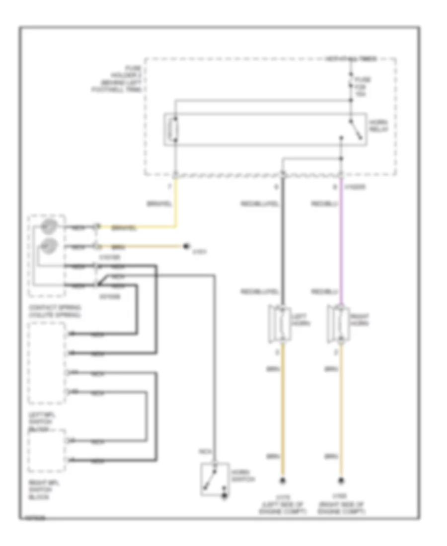
HORN Horn Wiring Diagram for MINI Cooper S 2003 List of elements for Horn Wiring Diagram for MINI Cooper S 2003: 18 (right side of engine compt) Contact spring (volute spring) Fuse f28 15a Fuse holder 2 (behind left footwell trim) Horn relay Horn switch Hot at all times Left horn Left mfl switch block Nca Right horn Right mfl switch block X01008 X10195 X10205 X151 X165 X175 (left side of engine compt)
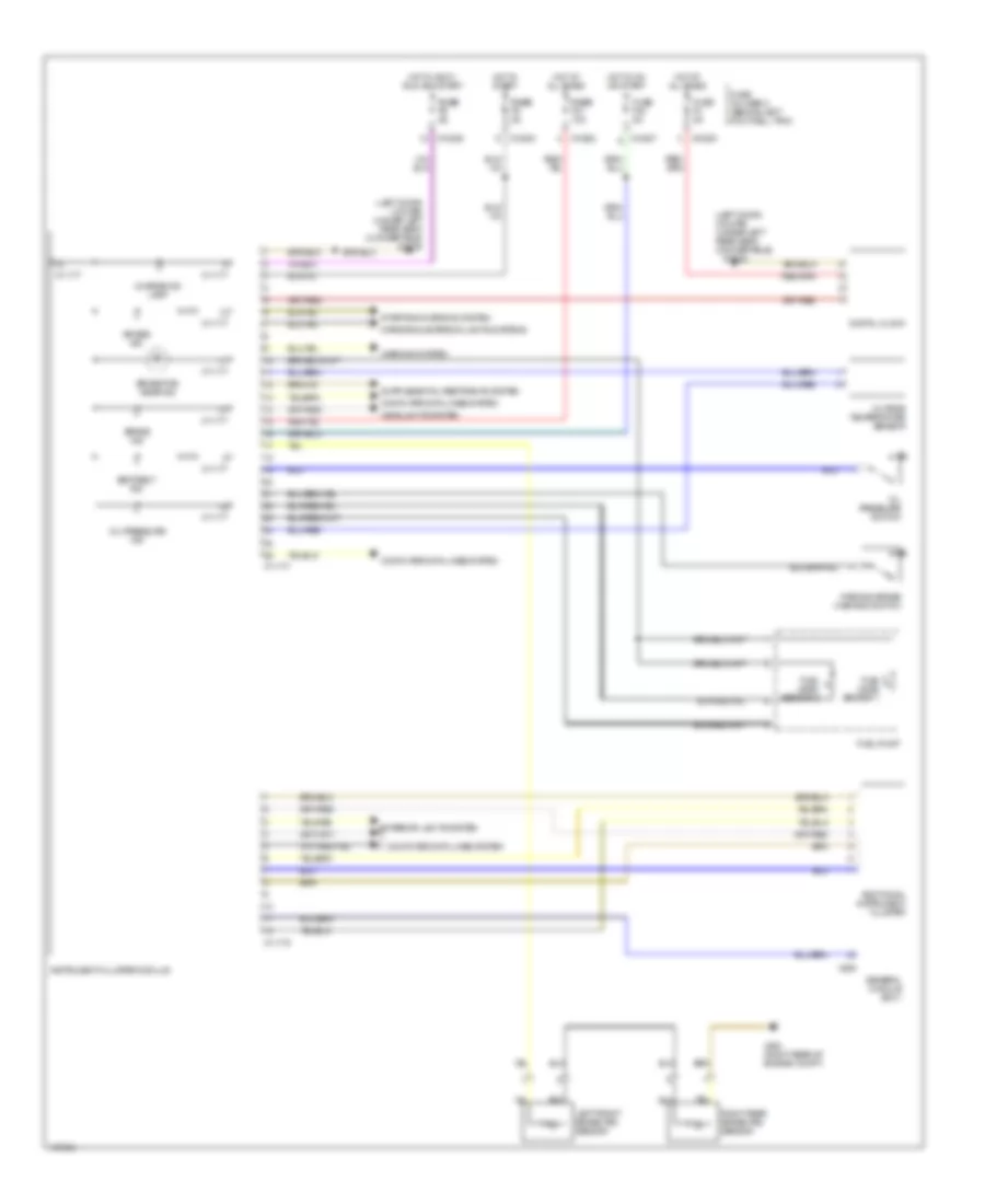
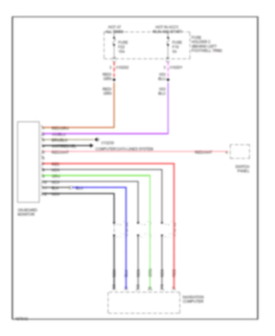
INSTRUMENT CLUSTER Instrument Cluster Wiring Diagram for MINI Cooper S 2003 List of elements for Instrument Cluster Wiring Diagram for MINI Cooper S 2003: 45 (left door) (coupe) (under left rear seat) (convertible) (left door) (coupe) (under left rear seat) (convertible) x13230 Additional instrument cluster Air bag ind Brake ind Brake pad wear ind Charge ind lamp Computer data lines system Digital clock Exterior lights system Fuel level sensor 1 Fuel level sensor 2 Fuel pump Fuse f3 5a Fuse f40 5a Fuse fuse f21 10a Fuse fuse f5 5a Fuse fuse f9 5a Fuse holder 2 (behind left footwell trim) General module (bc1) Headlights system Hot at all times Hot in accy, run and start Hot in on or start Hot in start Instrument cluster module Left front brake pad sensor Mirrors & exterior lights systems Oil pressure ind Oil pressure switch Outside temperature sensor Parking brake warning switch Right rear brake pad sensor Seat belt ind Starting/charging system Warning system X10200 X10202 X10206 X10207 X11175 X11177 X13230 X255 X494 (right rear of engine compt) On-Board Computer Wiring Diagram for MINI Cooper S 2003 List of elements for On-Board Computer Wiring Diagram for MINI Cooper S 2003: 14 Computer data lines system Fuse f10 5a Fuse f22 15a Fuse holder 2 (behind left footwell trim) Hot at all times Hot in accy, run and start Navigation computer Nca On-board monitor Red Switch panel X10201 X10202 X13230
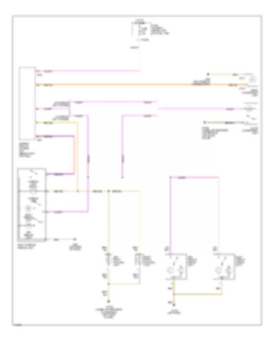
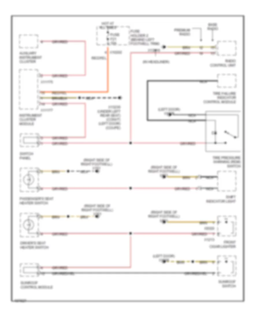
INTERIOR LIGHTS Courtesy Lamps Wiring Diagram for MINI Cooper S 2003 List of elements for Courtesy Lamps Wiring Diagram for MINI Cooper S 2003: 29 (left door) (under left rear seat) (convertible) (left door) (coupe) Cargo compartment light Front interior/ reading lamp Fuse f14 10a Fuse holder 2 (behind left footwell trim) General module control unit (behind right footwell) Glove compartment light Hot at all times Interior light Interior light switch Left front footwell light Left make-up mirror light Left reading light Right front footwell light Right make-up mirror light Right reading light W/ interior light package W/o interior light package X10206 X1108 X13230 X13230 (under left rear seat) (convertible) (left door) (coupe) X1740 X1741 X253 X332 X490 (left rear of trunk) X494 (right rear of luggage compt) Instrument Illumination Wiring Diagram for MINI Cooper S 2003 List of elements for Instrument Illumination Wiring Diagram for MINI Cooper S 2003: 28 (in headliner) (left door) x1108 (right side of right footwell) x151 Auxiliary instrument cluster Base radio Driver's seat heater switch Front cigar lighter Fuse f21 10a Fuse holder 2 (behind left footwell trim) Hot at all times Instrument cluster module Nca Passenger's seat heater switch Premium radio Radio control unit Shift indicator light Sunroof control module Sunroof switch Switch panel Tire failure indicator control module Tire pressure warning (rdm) switch X10202 X11175 X11177 X1213 X13016 X13230 (under left rear seat) (convt) (left door) (coupe) X9320
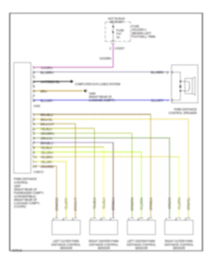
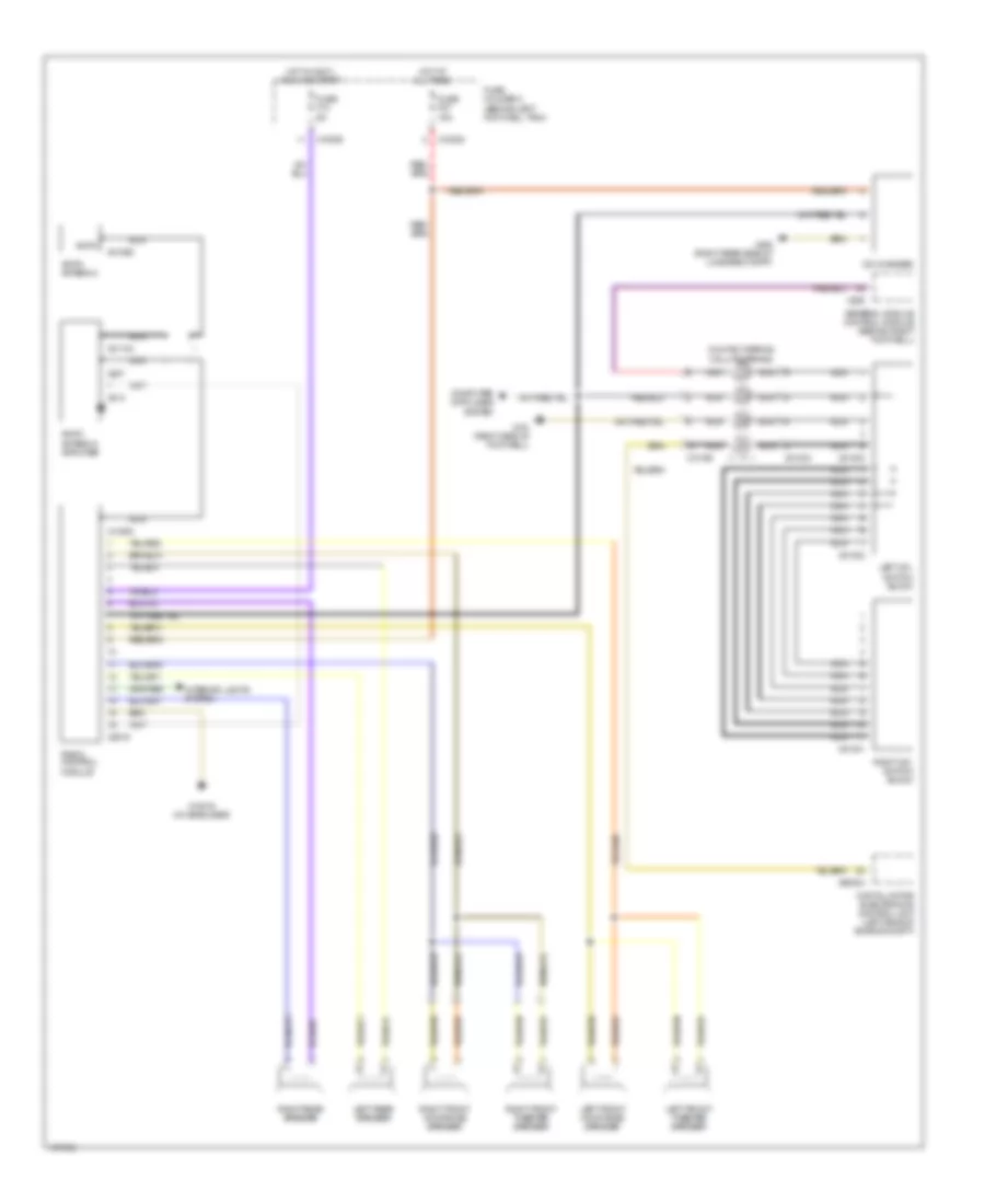
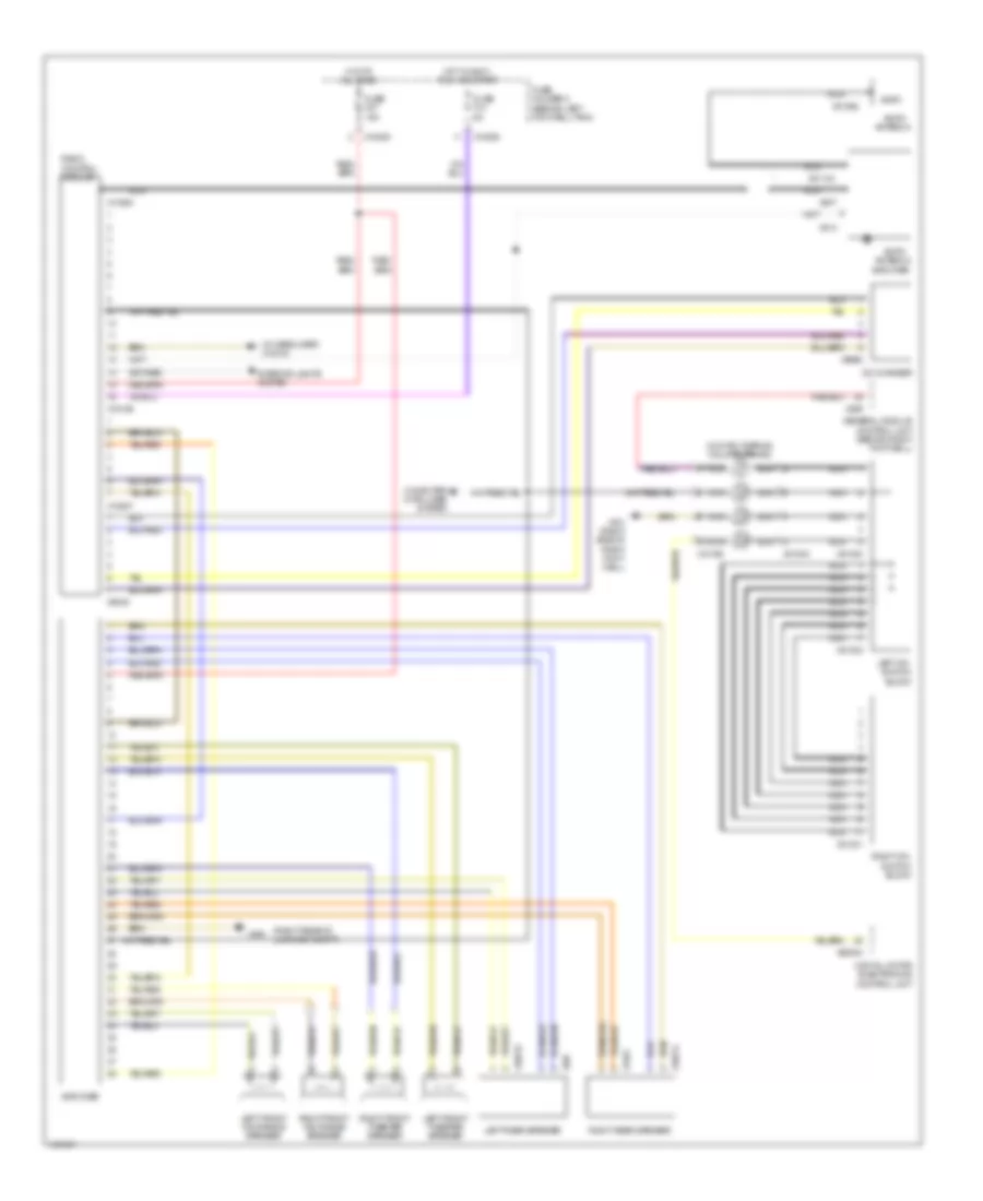
NAVIGATION Navigation Wiring Diagram for MINI Cooper S 2003 List of elements for Navigation Wiring Diagram for MINI Cooper S 2003: 32 (convertible) (coupe) (right rear of engine compt) Abs control module (right rear of engine compt) Abs/dsc control module Amplifier (below passenger's seat) (convertible) (right side of luggage compt) (coupe) Computer data lines system Exterior lights system Fuse f10 5a Fuse f22 15a Fuse holder 2 (behind left footwell trim) Gps antenna Hot at all times Hot in accy run and start Navigation computer (under right front seat) (coupe) (under left front seat) (convertible) Nca On-board monitor Radio control unit Red Switch panel W/ dsc W/o dsc X10201 X10202 X10266 X11 X1312 X1313 X13230 X1532 X1746 X179 (below right rear seat) (right door) Parking Assistant Wiring Diagram for MINI Cooper S 2003 List of elements for Parking Assistant Wiring Diagram for MINI Cooper S 2003: 14 Computer data lines system Fuse f41 5a Fuse holder 2 (behind left footwell trim) Hot in run or start Left center park distance control sensor Left outer park distance control sensor Park distance control speaker Park distance control unit (right rear of passenger compt) (convertible) (right rear of luggage compt) (coupe) Right center park distance control sensor Right outer park distance control sensor X10207 X18013 X300 X494 (right rear of luggage compt)
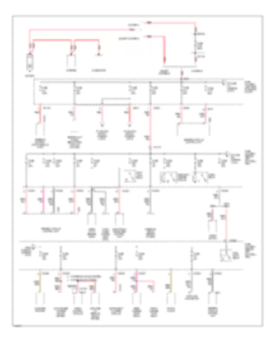
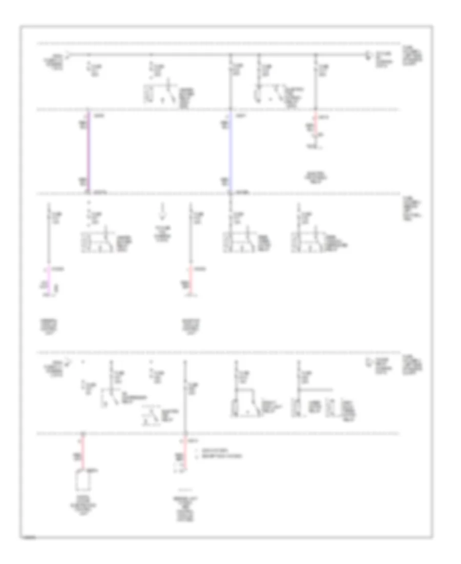
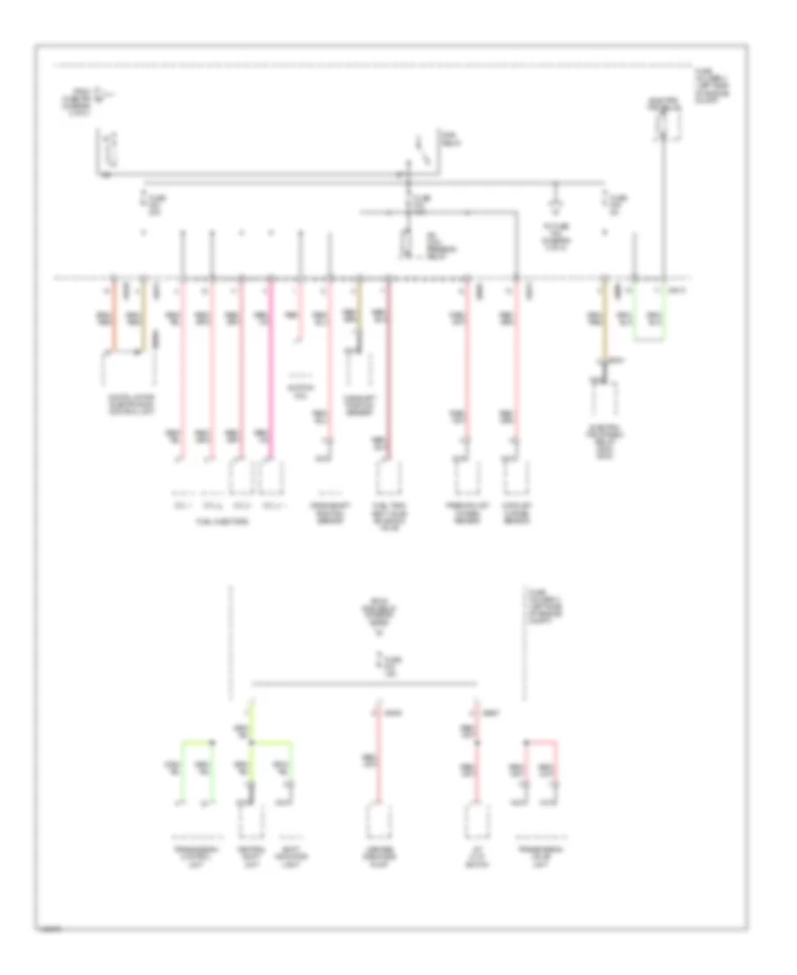
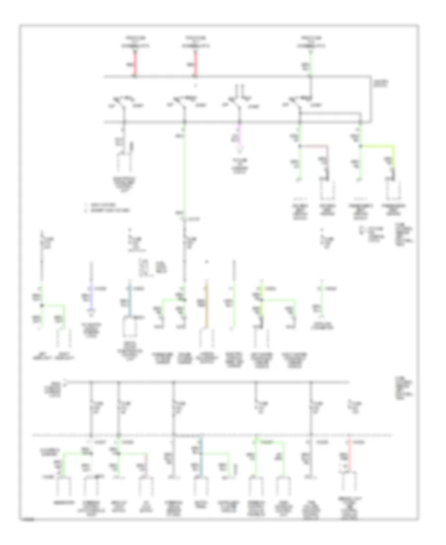
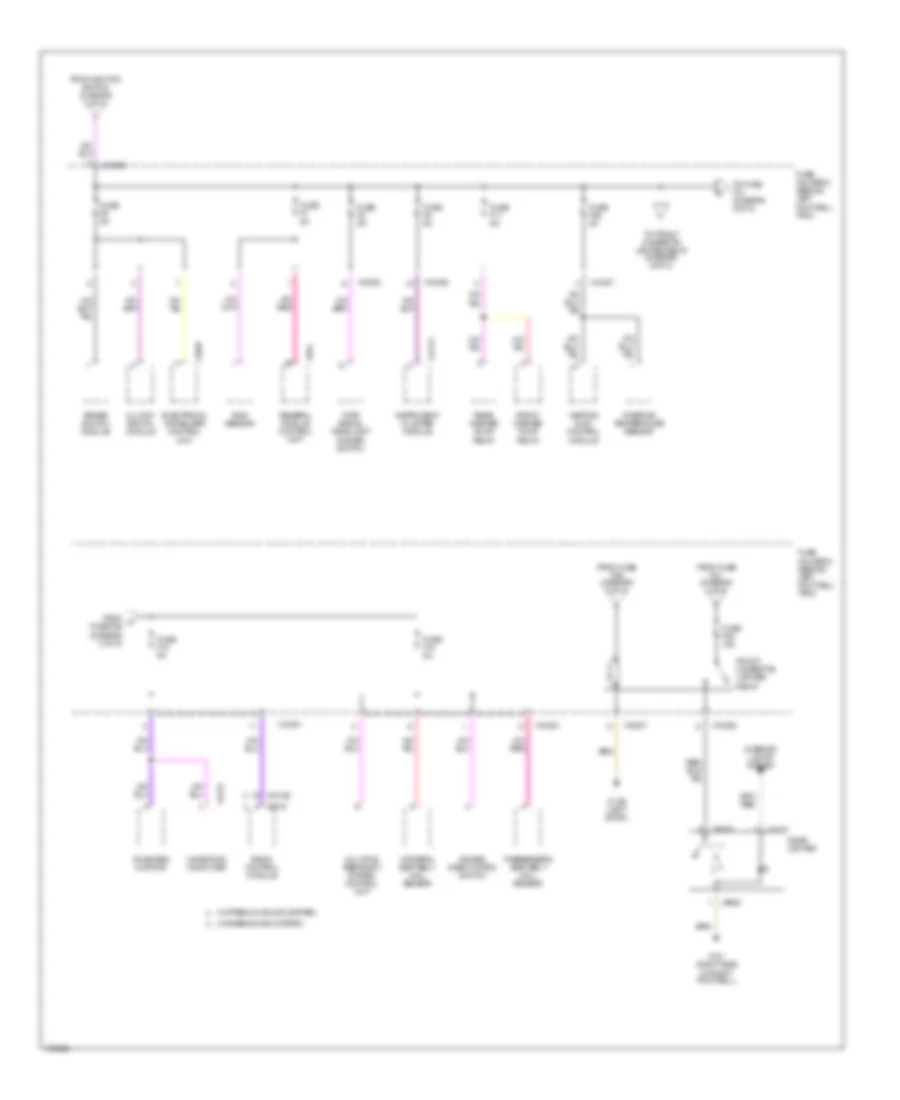
POWER DISTRIBUTION Power Distribution Wiring Diagram (1 of 5) for MINI Cooper S 2003 List of elements for Power Distribution Wiring Diagram (1 of 5) for MINI Cooper S 2003: 78 (w/ base sound system) (w/ premium sound system) 2003- Abs/dsc unit (w dsc) abs control module (w/o dsc) Alternator Amplifier (w/ premium sound system) Battery Cd changer (w/ base sound system) Cooper s Data link connector Digital clock Electronic immoblizer control unit Except cooper s From d fuse f20 (diagram 1 of 5) Front washer pump relay Fuel pump relay Fuse f1 30a Fuse f100 250a Fuse f19 30a Fuse f2 5a Fuse f20 20a Fuse f21 10a Fuse f22 15a Fuse f23 20a Fuse f24 5a Fuse f25 30a Fuse f26 10a Fuse f27 15a Fuse f28 15a Fuse f3 5a Fuse f37 20a Fuse f4 5a Fuse fl12 50a Fuse fl2 50a Fuse fl4 100a Fuse fl6 40a Fuse fl7 50a Fuse fl8 50a Fuse holder 2 (behind left footwell trim) Fuse holder 3 (left side of engine compt) General module control unit Headlight washer module Horn alarm system (2002- 2003) Horn relay Impact switch Instrument cluster module On-board monitor Radio control module Rear washer pump relay Red Red x01121 Shift lock relay Siren w/ tilt sensor (2004) Starter Steering angle sensor (w/ dsc) Steering control unit/hydraulic pump To fuse f22 (diagram 1 of 5) To fuse fl1 (diagram 2 of 5) To ignition switch (diagram 4 of 5) X01122 X01123 X10178 X10200 X10201 X10202 X10204 X10205 X10207 X11177 X13441 X18126 X2519 X254 X332 X4008 X4009 X4010 X819 Power Distribution Wiring Diagram (2 of 5) for MINI Cooper S 2003 List of elements for Power Distribution Wiring Diagram (2 of 5) for MINI Cooper S 2003: 51 (2004 w/o dsc) (except 2004 w/o dsc) A/c compressor relay Abs/dsc unit (w dsc) abs control module (w/o dsc) Digital motor electronics control unit Electric fan relay Electric fan stage 2 relay Electric fan stage 2 relay (2004) Fast/ slow wiper motor relay From a fuse fl12 (diagram 1 of 5) From e fuse fl11 (diagram 2 of 5) Front fog light relay Fuse f01 5a Fuse f010 15a Fuse f06 30a Fuse f07 30a Fuse f08 30a Fuse f09 20a Fuse f14 10a Fuse f15 20a Fuse f16 30a Fuse f17 15a Fuse f31 30a Fuse fl1 50a Fuse fl11 50a Fuse fl5 50a Fuse fl9 30a Fuse fl9 50a Fuse holder 2 (behind left footwell trim) Fuse holder 3 (left side of engine compt) General module control unit Heater blower relay (2002- 2003) Heater blower relay (2004) Nca Rear window defroster relay Rear wiper motor relay Sunroof module control unit To dme relay (diagram 3 of 5) To fuse f01 (diagram 2 of 5) To fuse f32 (diagram 5 of 5) Wiper motor relay X10178 X10199 X10206 X332 X4007 X4008 X4013 X4015 X53 X60004 Power Distribution Wiring Diagram (3 of 5) for MINI Cooper S 2003 List of elements for Power Distribution Wiring Diagram (3 of 5) for MINI Cooper S 2003: 39 (diagram 2 of 5 ) A/c com- pressor relay A/t (cvt) switch Camshaft position sensor Catalyst oxygen sensor Central shift unit Crankshaft position sensor Cyl 1 Cyl 2 Cyl 3 Cyl 4 Digital motor electronics control unit Dme relay Electric fan relay Electric fan stage 2 relay (2002- 2003) From dme relay (diagram 3 of 5) From fuse f09 g Fuel injectors Fuel tank vent valve solenoid valve Fuse f02 20a Fuse f03 15a Fuse f04 15a Fuse f05 5a Fuse holder 3 (left side of engine compt) Ignition coil Leakage diagnosis pump Nca Precatalyst oxygen sensor Red Shift indicator light To fuse f04 (diagram 3 of 5) Transmission control unit Transmission valve unit X4009 X4010 X4013 X5301 X60004 X8687 Power Distribution Wiring Diagram (4 of 5) for MINI Cooper S 2003 List of elements for Power Distribution Wiring Diagram (4 of 5) for MINI Cooper S 2003: 64 (2004 w/o dsc) (cooper s & denso) (except 2004 w/o dsc) (valeo) A/t (cvt) switch Abs/dsc unit (w dsc) abs control module (w/o dsc) Acc Back-up light switch Data link connector Digital motor electronics control unit Driver outside mirror Driver's seat heating Driver's seat heating switch Electro- chromic rear view mirror Electronic immoblizer control unit From fuse f12 (diagram 4 of 5) From fuse fl7 (diagram 1 of 5) From k fuse f36 (diagram 4 of 5) Fuel pump relay Fuse f12 20a Fuse f13 5a Fuse f30 5a Fuse f33 10a Fuse f34 10a Fuse f35 5a Fuse f36 5a Fuse f39 5a Fuse f40 5a Fuse f41 5a Fuse holder 2 (behind left footwell trim) Generator Ignition switch Instrument cluster module Left headlight Left heated windshield washer nozzle Mirror adjustment switch Nca Off Park distance control unit Passenger outside mirror Passenger's seat heating Passenger's seat heating switch Red Right headlight Right heated windshield washer nozzle Run Start Steering angle sensor (w/ dsc) Steering control module fan relay Steering control unit/hydraulic pump Switch panel Tire failure indicator control module To fuse f39 (diagram 4 of 5) To fuse f6 (diagram 5 of 5) To ignition switch (diagram 4 of 5) X10178 X10204 X10205 X10206 X10207 X11177 X1659 X60004 X6975 Power Distribution Wiring Diagram (5 of 5) for MINI Cooper S 2003 List of elements for Power Distribution Wiring Diagram (5 of 5) for MINI Cooper S 2003: 55 (w/ base sound system) (w/ premium sound system) Air bag deactivation switch Brake switch module Cigar lighter Clutch switch module Driver's seat belt hall sensor Electronic immoblizer control unit From fuse f29 (diagram 5 of 5) From fuse f31 (diagram 2 of 5) From ignition switch (diagram 4 of 5) From m fuse f29 (diagram 5 of 5) Front cigarette lighter relay Front washer pump relay Fuse f10 5a Fuse f11 5a Fuse f18 5a Fuse f29 5a Fuse f32 15a Fuse f6 5a Fuse f7 5a Fuse f8 5a Fuse f9 5a Fuse holder 2 (behind left footwell trim) General module control unit Heating & a/c control module Instrument cluster module Interior lights system Interior temperature sensor Multiple restraint system control unit Navigation computer On-board monitor Passenger's seat belt hall sensor Radio control module Rain sensor Rear washer pump relay To front cigarette lighter relay (diagram 5 of 5) To fuse f10 (diagram 5 of 5) Turn signal/ headlight dimmer switch X10199 X10200 X10201 X10203 X10206 X10207 X1108 (left door) X11177 X1213 X1313 X151 (right side of right footwell) X1659 X18126 X2519 X254 X9320
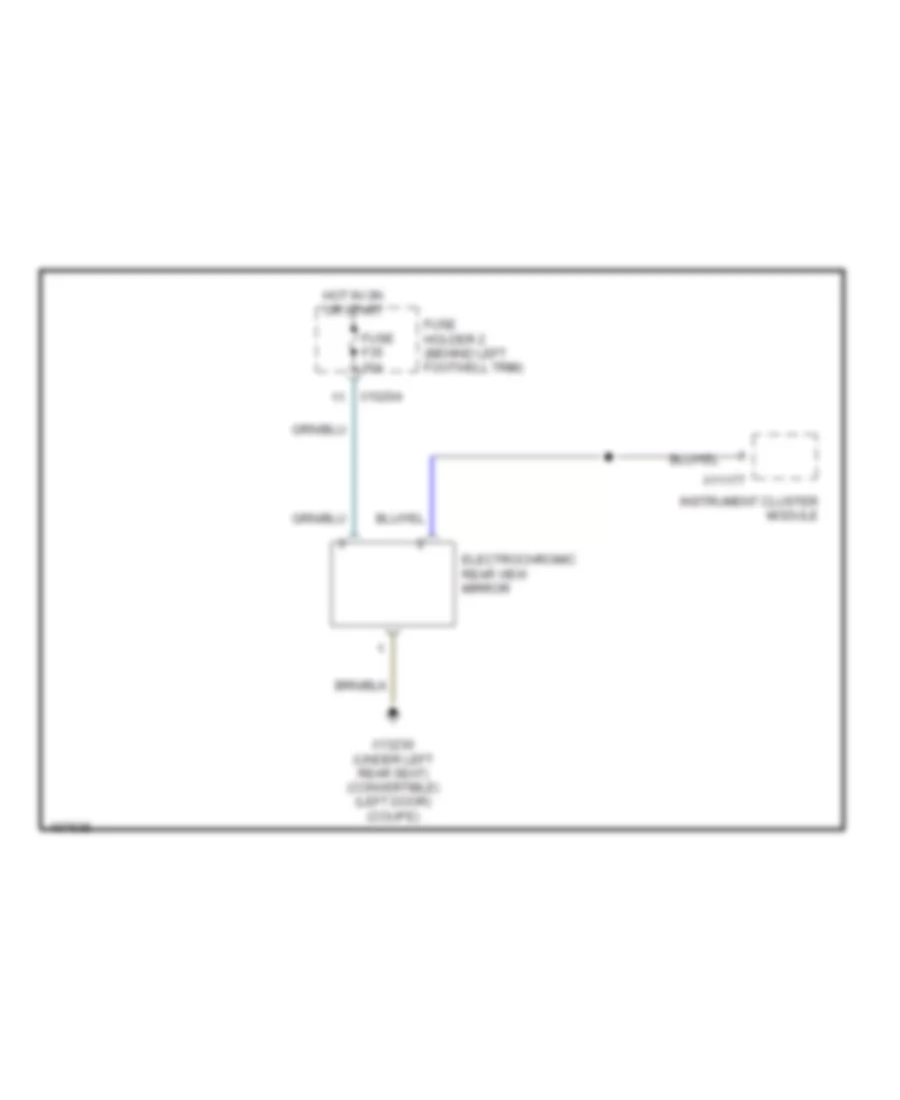
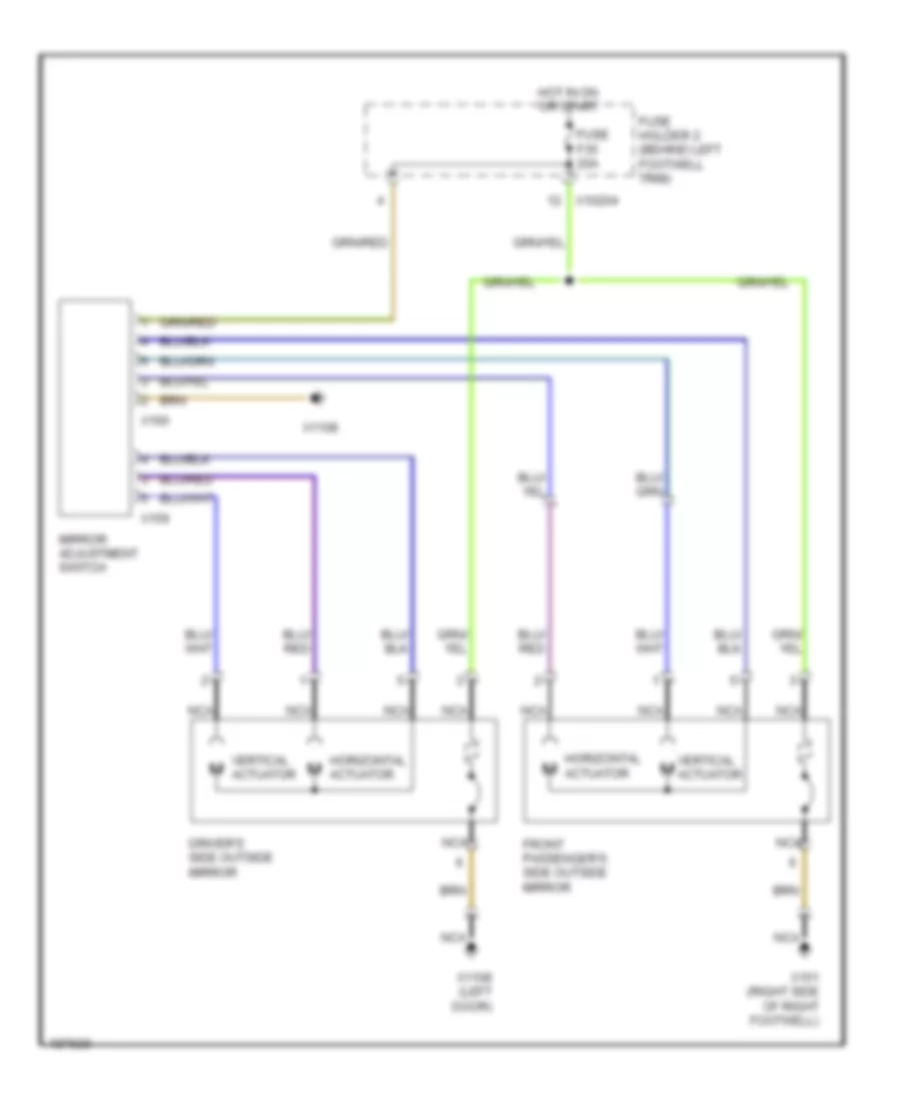
POWER MIRRORS Electrochromic Mirror Wiring Diagram for MINI Cooper S 2003 List of elements for Electrochromic Mirror Wiring Diagram for MINI Cooper S 2003: 8 Electrochromic rear view mirror Fuse f35 20a Fuse holder 2 (behind left footwell trim) Hot in on or start Instrument cluster module X10204 X11177 X13230 (under left rear seat) (convertible) (left door) (coupe) Power Mirror Wiring Diagram for MINI Cooper S 2003 List of elements for Power Mirror Wiring Diagram for MINI Cooper S 2003: 16 Driver's side outside mirror Front passenger's side outside mirror Fuse f35 20a Fuse holder 2 (behind left footwell trim) Horizontal actuator Hot in on or start Mirror adjustment switch Nca Vertical actuator Vertical m actuator X10204 X1108 X1108 (left door) X151 (right side of right footwell) X159 X160
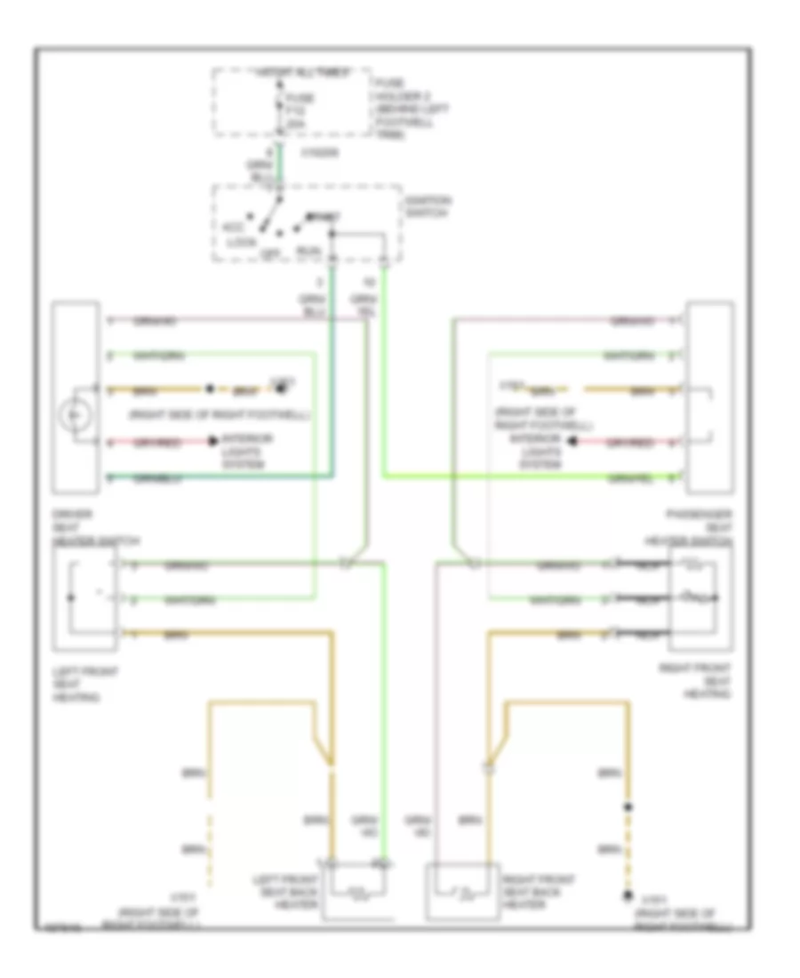
POWER SEATS Heated Seats Wiring Diagram for MINI Cooper S 2003 List of elements for Heated Seats Wiring Diagram for MINI Cooper S 2003: 20 (right side of right footwell) Acc Driver seat heater switch Fuse f12 20a Fuse holder 2 (behind left footwell trim) Hot at all times Ignition switch Interior lights system Left front seat back heater Left front seat heating Lock Nca Off Passenger seat heater switch Right front seat back heater Right front seat heating Run Start X10206 X151
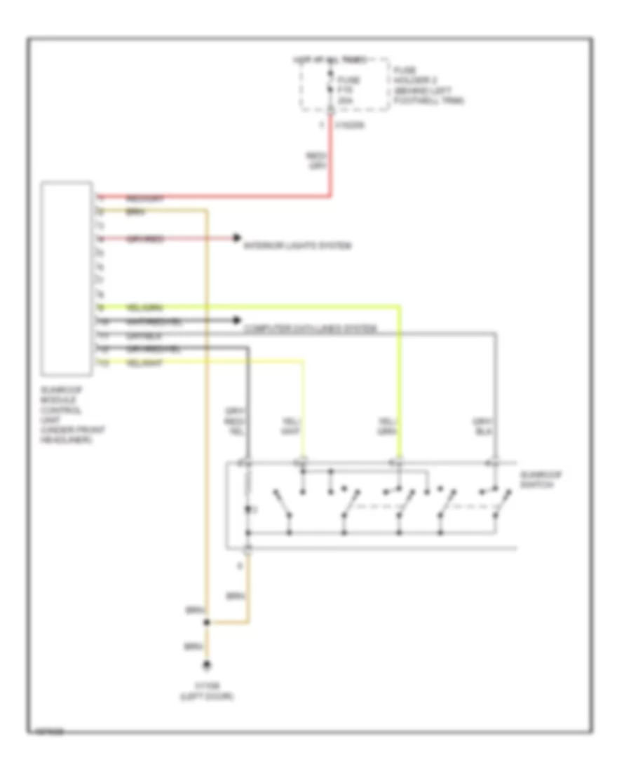
POWER TOP/SUNROOF Power Top/Sunroof Wiring Diagram for MINI Cooper S 2003 List of elements for Power Top/Sunroof Wiring Diagram for MINI Cooper S 2003: 9 Computer data lines system Fuse f15 20a Fuse holder 2 (behind left footwell trim) Hot at all times Interior lights system Sunroof module control unit (under front headliner) Sunroof switch X10206 X1108 (left door)
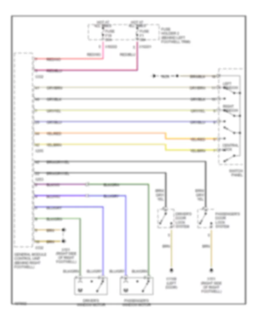
POWER WINDOWS Power Windows Wiring Diagram for MINI Cooper S 2003 List of elements for Power Windows Wiring Diagram for MINI Cooper S 2003: 23 (right side of right footwell) Central lock Driver's door lock system Driver's window motor Fuse f1 30a Fuse f19 30a Fuse holder 2 (behind left footwell trim) General module control unit (behind right footwell) Hot at all times Left window Nca Passenger's door lock system Passenger's window motor Right window Switch panel X10201 X10202 X1108 (left door) X151 X151 (right side of right footwell) X253 X255 X332
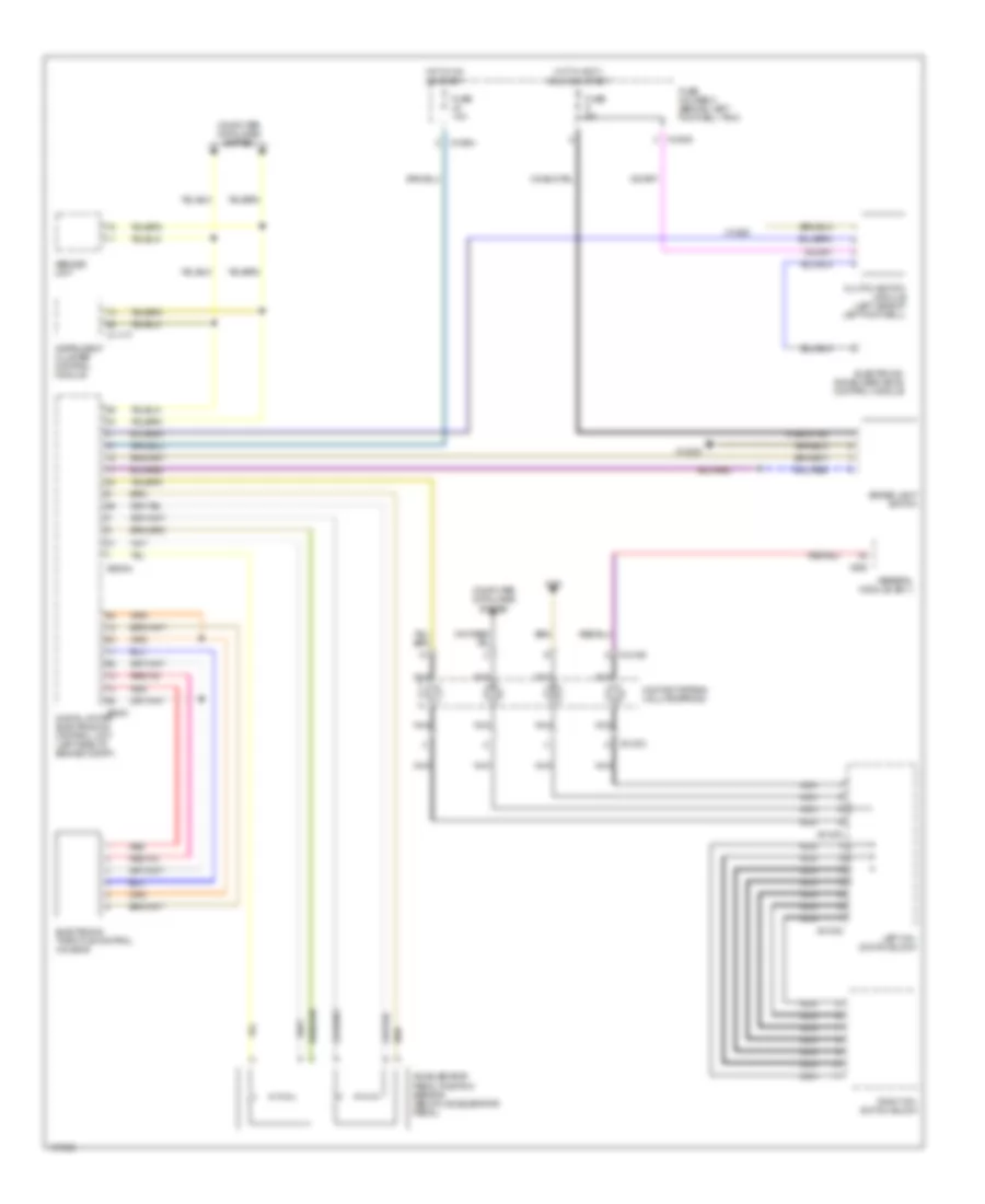
RADIO Base Radio Wiring Diagram for MINI Cooper S 2003 List of elements for Base Radio Wiring Diagram for MINI Cooper S 2003: 42 Am/fm Am/fm antenna Am/fm antenna amplifier Cd changer Computer data lines system Contact spring (volute spring) Digital motor electronics control unit (left side of engine compt) Fuse f10 5a Fuse f27 15a Fuse holder 2 (behind left footwell trim) General module control module (behind right footwell) Hot at all times Hot in accy, run and start Interior lights system Left front mid-range speaker Left front tweeter speaker Left mfl switch block Left rear speaker Nca Radio control module Right front mid-range speaker Right front tweeter speaker Right mfl switch block Right rear speaker X01000 X01001 X01002 X01003 X01068 X01104 X10195 X10205 X10206 X13016 (in headliner) X13364 X151 (right side of footwell) X2519 X255 X494 (right rear side of luggage compt) X60004 X807 X813 Premium Sound Radio Wiring Diagram for MINI Cooper S 2003 List of elements for Premium Sound Radio Wiring Diagram for MINI Cooper S 2003: 50 (in headliner) x13016 (right rear of luggage compt) Am/fm Amplifier Antenna Cd changer Computer data lines system Contact spring (volute spring) Digital motor electronics control unit Fuse f10 5a Fuse f27 15a Fuse holder 2 (behind left footwell trim) General module control unit (behind right footwell) Hot at all times Hot in accy, run and start Interior lights system Left front mid-range speaker Left front tweeter speaker Left mfl switch block Left rear speaker Nca Radio control module Right front mid-range speaker Right front tweeter speaker Right mfl switch block Right rear speaker X01000 X01001 X01002 X01003 X01068 X01104 X10195 X10205 X10206 X1261 X13364 X13647 X151 (right side of right foot- well) X18126 X18514 X18515 X255 X397 X494 X60004 X807 X813 X9345 X9960
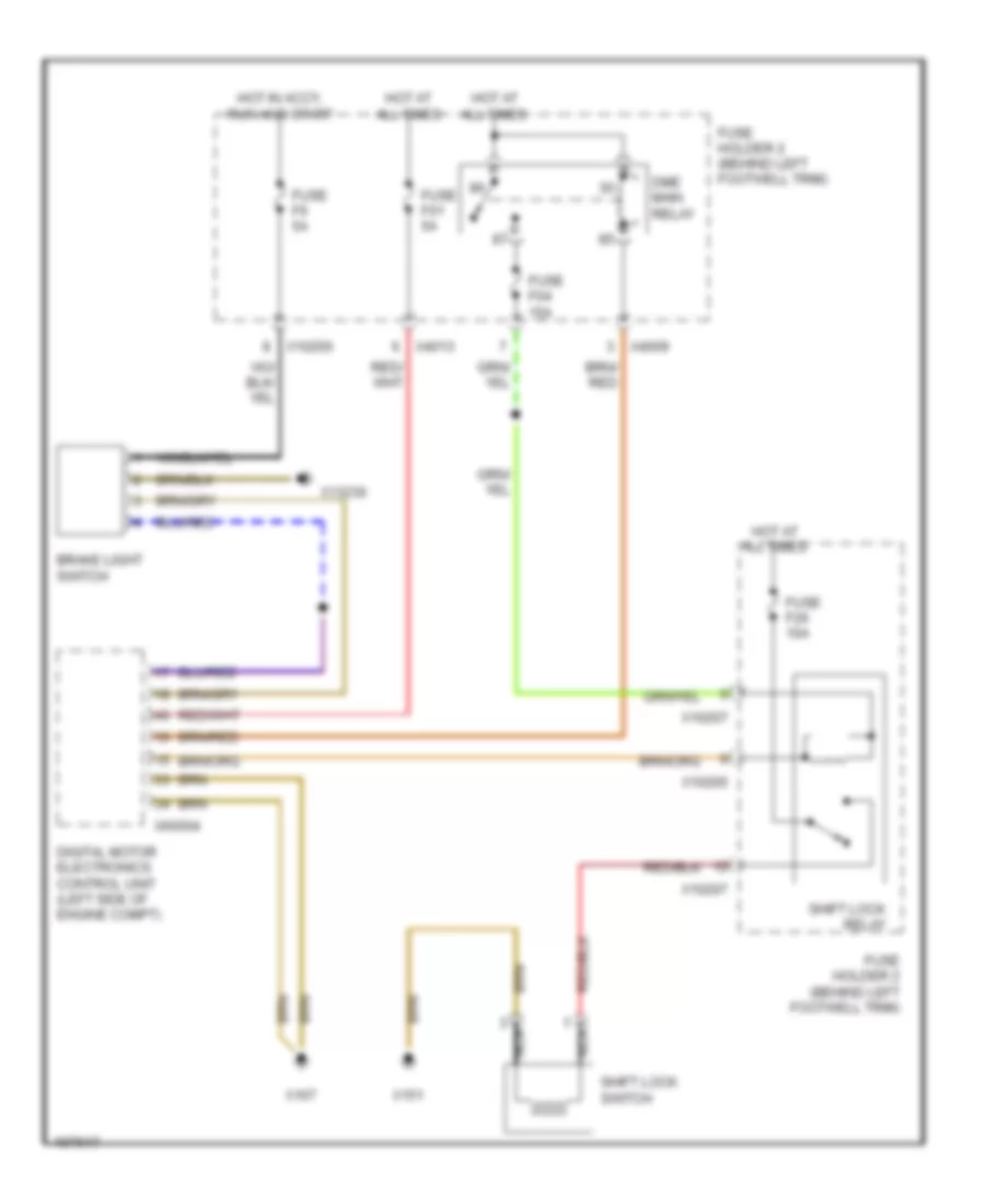
SHIFT INTERLOCK Shift Interlock Wiring Diagram for MINI Cooper S 2003 List of elements for Shift Interlock Wiring Diagram for MINI Cooper S 2003: 22 Brake light switch Digital motor electronics control unit (left side of engine compt) Dme main relay Fuse f01 5a Fuse f04 15a Fuse f26 10a Fuse f6 5a Fuse holder 2 (behind left footwell trim) Hot at all times Hot in accy, run and start Nca Shift lock relay Shift lock switch X10200 X10205 X10207 X13230 X151 X167 X4009 X4013 X60004
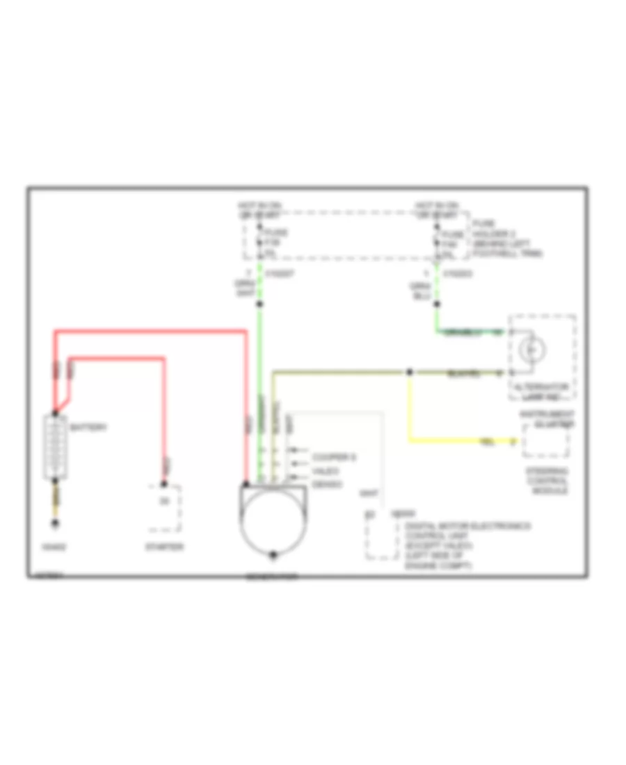
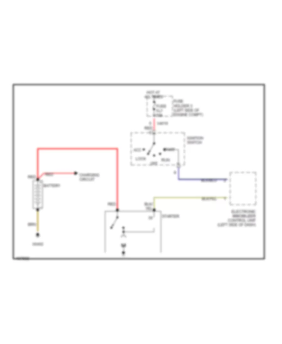
STARTING/CHARGING Charging Wiring Diagram for MINI Cooper S 2003 List of elements for Charging Wiring Diagram for MINI Cooper S 2003: 19 Alternator lamp ind Battery Cooper s Denso Digital motor electronics control unit (except valeo) (left side of engine compt) Fuse f39 5a Fuse f40 5a Fuse holder 2 (behind left footwell trim) Generator Hot in on or start Instrument cluster Red Starter Steering control module Valeo X10203 X10207 X6000 X6402 Starting Wiring Diagram for MINI Cooper S 2003 List of elements for Starting Wiring Diagram for MINI Cooper S 2003: 16 Acc Battery Charging circuit Electronic immobilizer control unit (left side of dash) Fuse fl7 50a Fuse holder 3 (left side of engine compt) Hot at all times Ignition switch Lock Off Red Run Start Starter X4010 X6402
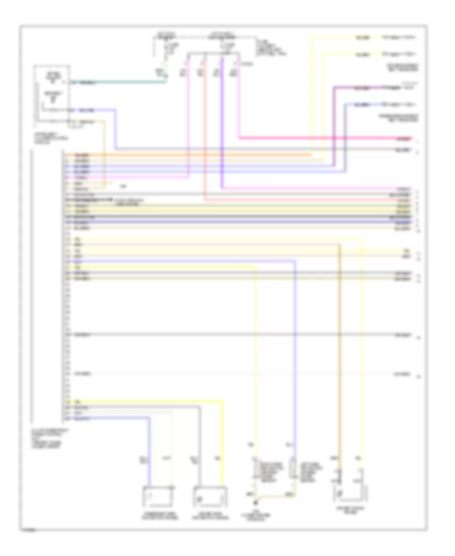
SUPPLEMENTAL RESTRAINTS Supplemental Restraints Wiring Diagram (1 of 2) for MINI Cooper S 2003 List of elements for Supplemental Restraints Wiring Diagram (1 of 2) for MINI Cooper S 2003: 22 Air bag ind lamp Computer data lines system Driver head protection air bag Driver side seat belt tensioner Driver thorax air bag Fuse f18 5a Fuse f40 5a Fuse holder 2 (behind left footwell trim) Hot in accy, run and start Hot in on or start Instrument cluster control module Left head protection air bags crash sensor Multiple restraint system control unit (center tunnel under carpet) Nca Passenger head protection air bag Passenger side seat belt tensioner Right head protection air bags crash sensor Seat belt ind X10203 X11177 X46 X46 (under center console) Supplemental Restraints Wiring Diagram (2 of 2) for MINI Cooper S 2003 List of elements for Supplemental Restraints Wiring Diagram (2 of 2) for MINI Cooper S 2003: 21 (under center console) Air bag deactivation switch Contact spring (volute spring) Driver air bag Driver's seat belt hall sensor Nca Passenger air bag Passenger air bag deactivation indicator lamp Passenger thorax air bag Passenger's seat belt hall sensor W/ air bag deactivation W/o air bag deactivation X01099 X01156 X01157 X11558 X13230 (under left rear seat) (convertible) (left door) (coupe) X18170 X18170 (under center console) X19565 X783
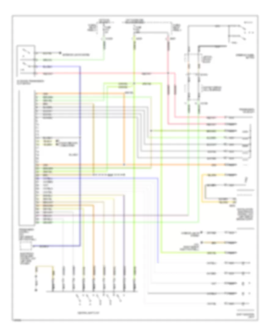
TRANSMISSION Transmission Wiring Diagram for MINI Cooper S 2003 List of elements for Transmission Wiring Diagram for MINI Cooper S 2003: 27 Automatic transmission (cvt) switch Central shift unit Computer data lines system Contact spring (volute spring) Digital motor electronics control unit (left side of engine compt) Electronic immobilizer control unit (left side of dash) Exterior lights system Fuse & relay panel 2 Fuse & relay panel 3 Fuse f04 15a Fuse f13 5a Hot in on or start Hot w/ dme main relay energized Interior lights system Left mfl switch block Nca Shift indicator light Steering wheel button Transmission control unit (left side of left footwell) Transmission valve unit X01003 X10195 X10206 X151 (right side of right footwell) X4009 X6000 X8687
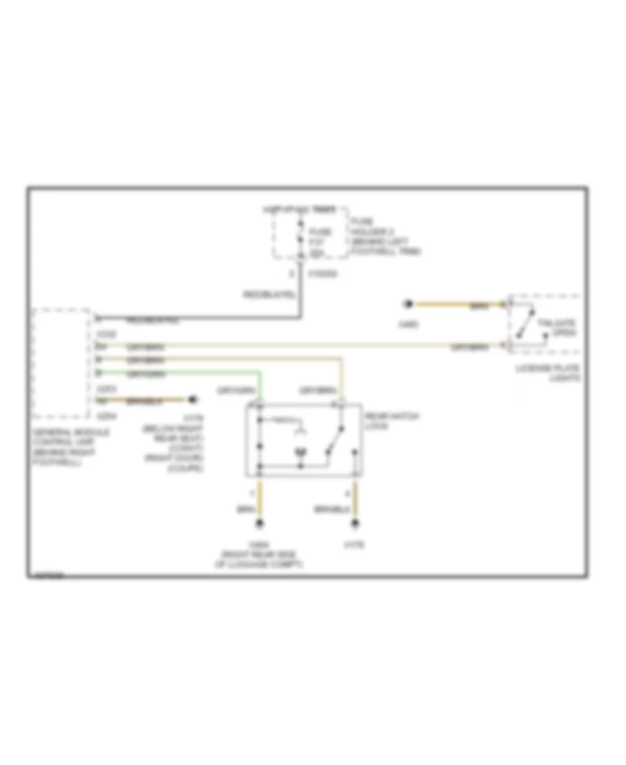
TRUNK, TAILGATE, FUEL DOOR Trunk Release Wiring Diagram for MINI Cooper S 2003 List of elements for Trunk Release Wiring Diagram for MINI Cooper S 2003: 15 Fuse f37 20a Fuse holder 2 (behind left footwell trim) General module control unit (behind right footwell) Hot at all times License plate lights Rear hatch lock Tailgate open X10202 X179 X179 (below right rear seat) (convt) (right door) (coupe) X253 X254 X332 X490 X494 (right rear side of luggage compt)
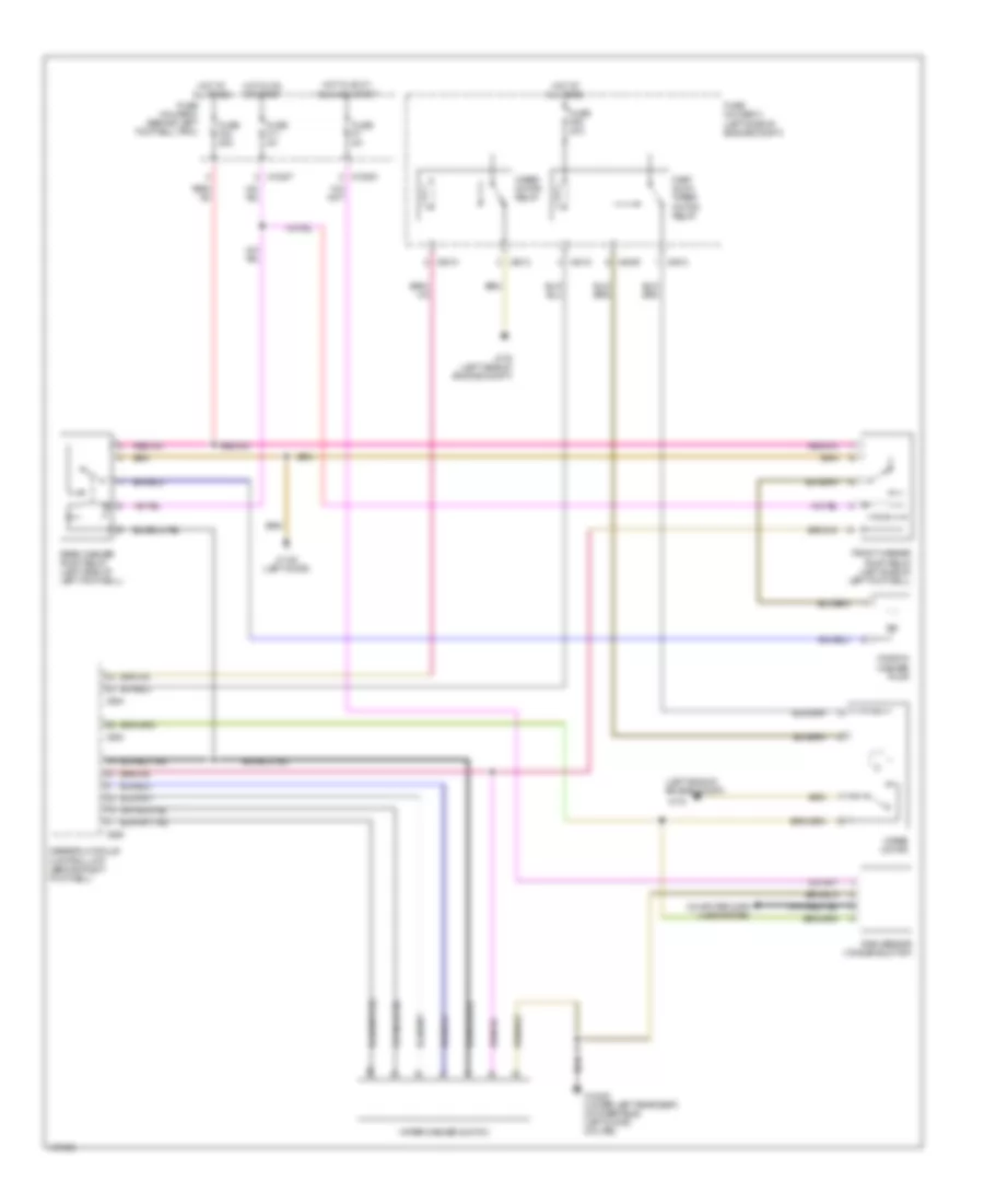
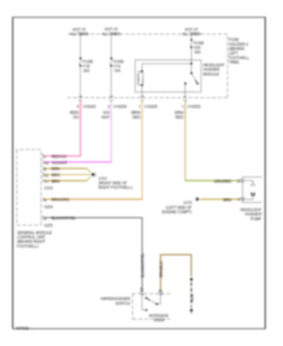
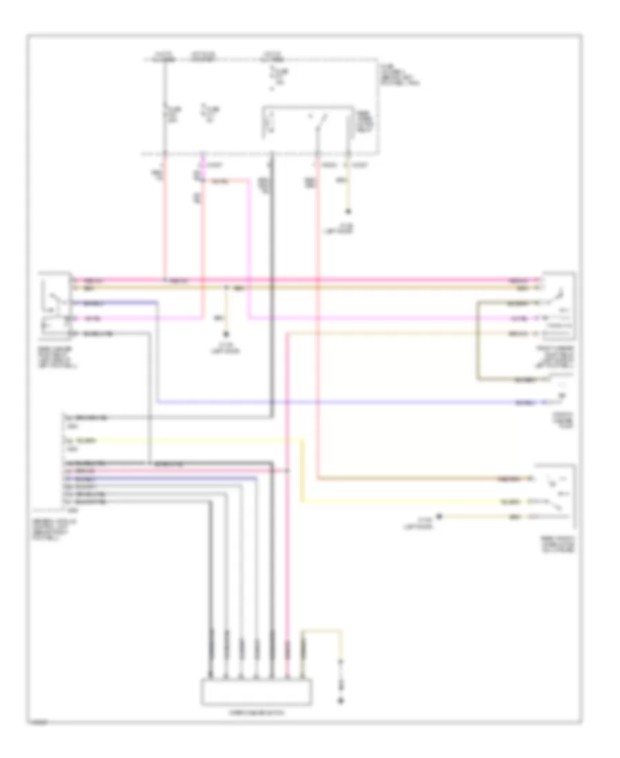
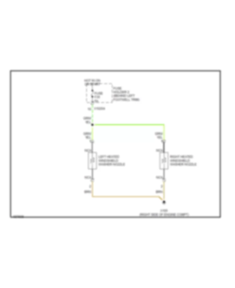
WIPER/WASHER Front Wiper/Washer Wiring Diagram for MINI Cooper S 2003 List of elements for Front Wiper/Washer Wiring Diagram for MINI Cooper S 2003: 34 (left side of engine compt) Computer data lines system Fast/ slow wiper motor relay Front washer pump relay (left side of left footwell) Fuse f09 20a Fuse f11 5a Fuse f23 20a Fuse f7 5a Fuse holder 2 (behind left footwell trim) Fuse holder 3 (left side of engine compt) General module control unit (behind right footwell) Hot at all times Hot in accy, Hot in on or start Nca Rain sensor (windshield top) Rear washer pump relay (left side of left footwell) Run and start Window washer pump Wiper motor Wiper motor relay Wiper/washer switch X10200 X10207 X1108 (left door) X13230 (under left rear seat) (convertible) (left door) (coupe) X175 X175 (left side of engine compt) X253 X254 X255 X4009 X4010 X4013 Headlamp Washer Wiring Diagram for MINI Cooper S 2003 List of elements for Headlamp Washer Wiring Diagram for MINI Cooper S 2003: 19 Fuse f14 10a Fuse f19 30a Fuse f25 30a Fuse holder 2 (behind left footwell trim) General module control unit (behind right footwell) Headlight washer module Headlight washer pump Hot at all times Intensive wash Nca Wiper/washer switch X10202 X10205 X10206 X151 (right side of right footwell) X175 (left side of engine compt) X254 X255 X332 Rear Wiper/Washer Wiring Diagram for MINI Cooper S 2003 List of elements for Rear Wiper/Washer Wiring Diagram for MINI Cooper S 2003: 22 (left door) Front washer pump relay (left side of left footwell) Fuse f11 5a Fuse f17 15a Fuse f23 20a Fuse holder 2 (behind left footwell trim) General module control unit (behind right footwell) Hot at all times Hot in on or start Nca Rear washer pump relay (left side of left footwell) Rear window wiper motor (on liftgate) Rear wiper motor relay Window washer pump Wiper/washer switch X10204 X10207 X1108 X1108 (left door) X253 X254 X255 Washer Jet Heater Wiring Diagram for MINI Cooper S 2003 List of elements for Washer Jet Heater Wiring Diagram for MINI Cooper S 2003: 8 Fuse f35 5a Fuse holder 2 (behind left footwell trim) Hot in on or start Left heated windshield washer nozzle Nca Right heated windshield washer nozzle X10204 X165 (right side of engine compt)