Diagram sections — 29 (67 total)
AIR CONDITIONING ANTI-LOCK BRAKES ANTI-THEFT BODY CONTROL MODULES COMPUTER DATA LINES COOLING FAN CRUISE CONTROL DEFOGGERS ENGINE PERFORMANCE EXTERIOR LIGHTS GROUND DISTRIBUTION HEADLIGHTS HORN INSTRUMENT CLUSTER INTERIOR LIGHTS NAVIGATION POWER DISTRIBUTION POWER DOOR LOCKS POWER MIRRORS POWER SEATS POWER TOP/SUNROOF POWER WINDOWS RADIO STARTING/CHARGING SUPPLEMENTAL RESTRAINTS TRANSMISSION TRUNK, TAILGATE, FUEL DOOR WARNING SYSTEMS WIPER/WASHER
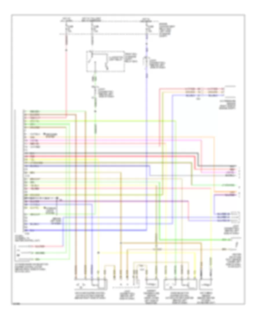
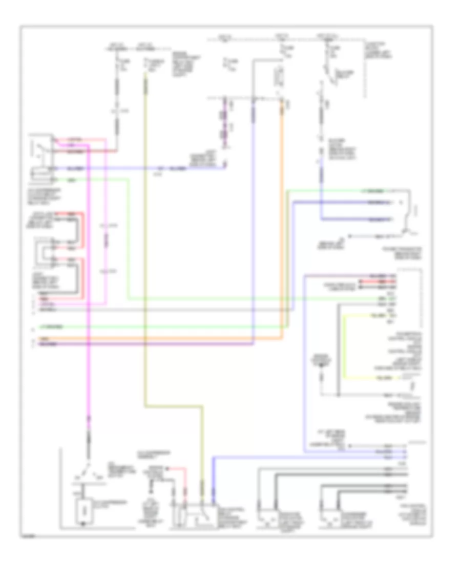
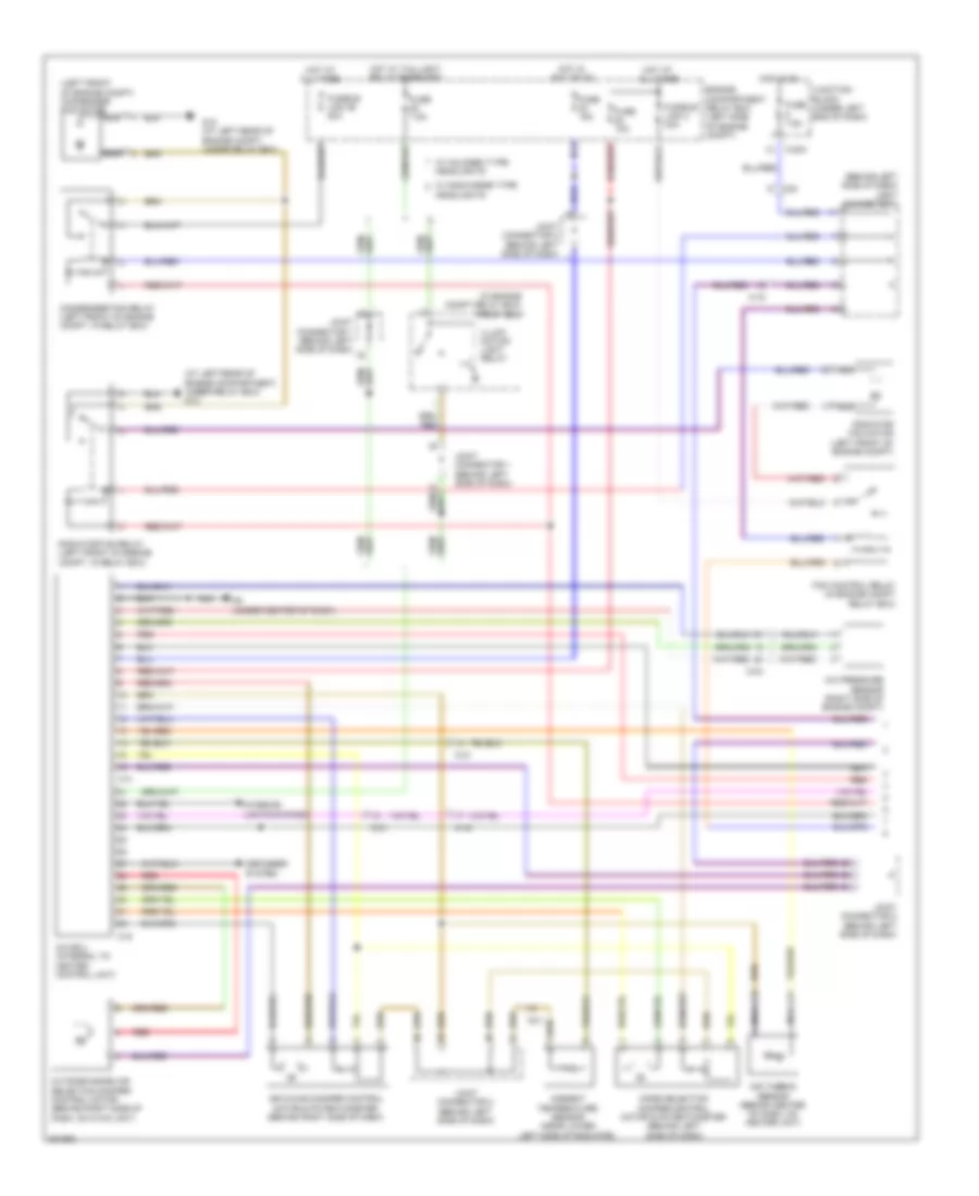
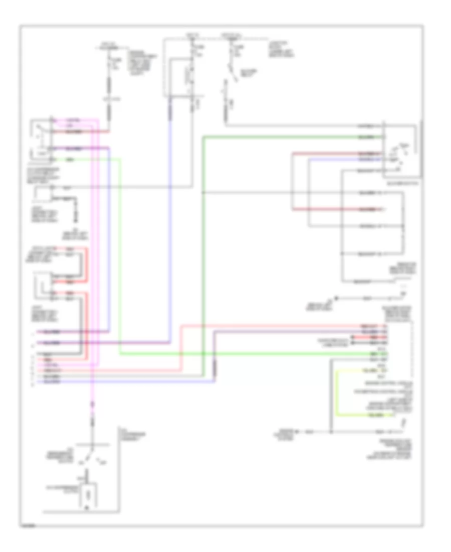
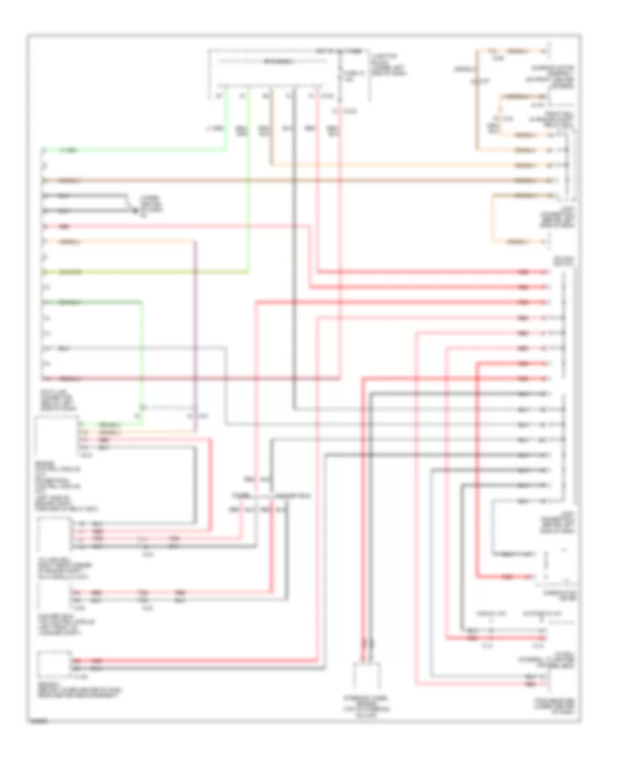
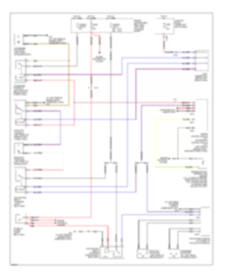
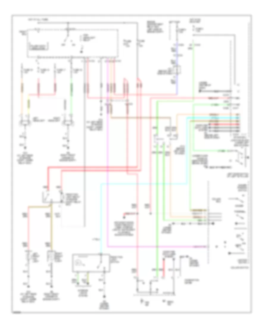
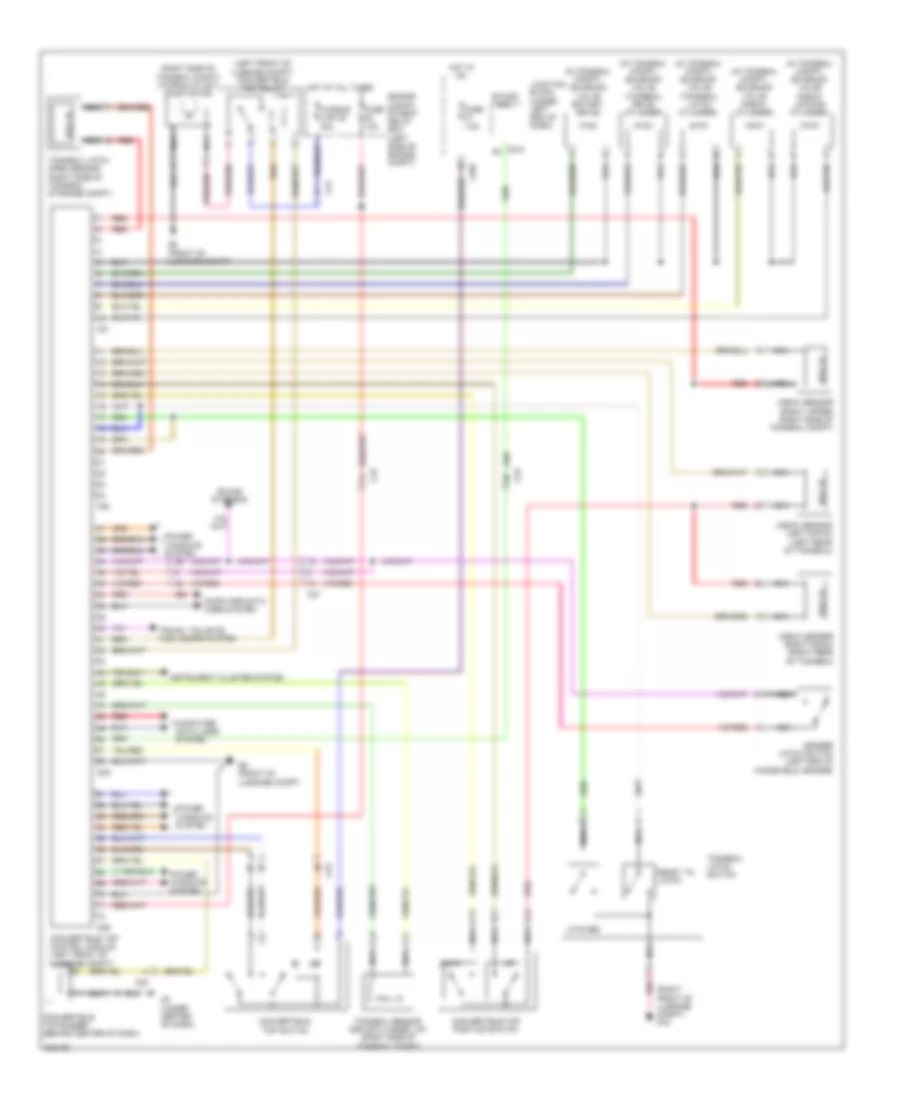
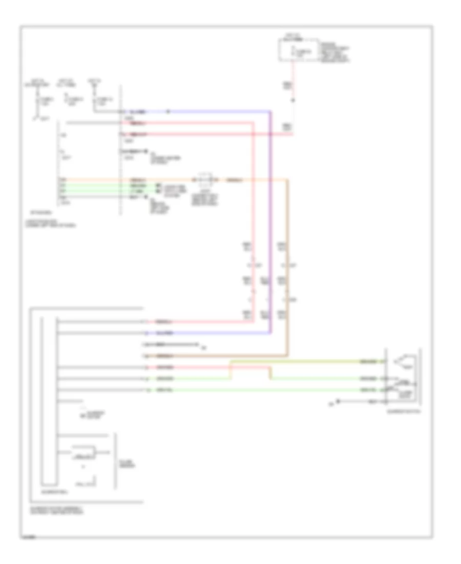
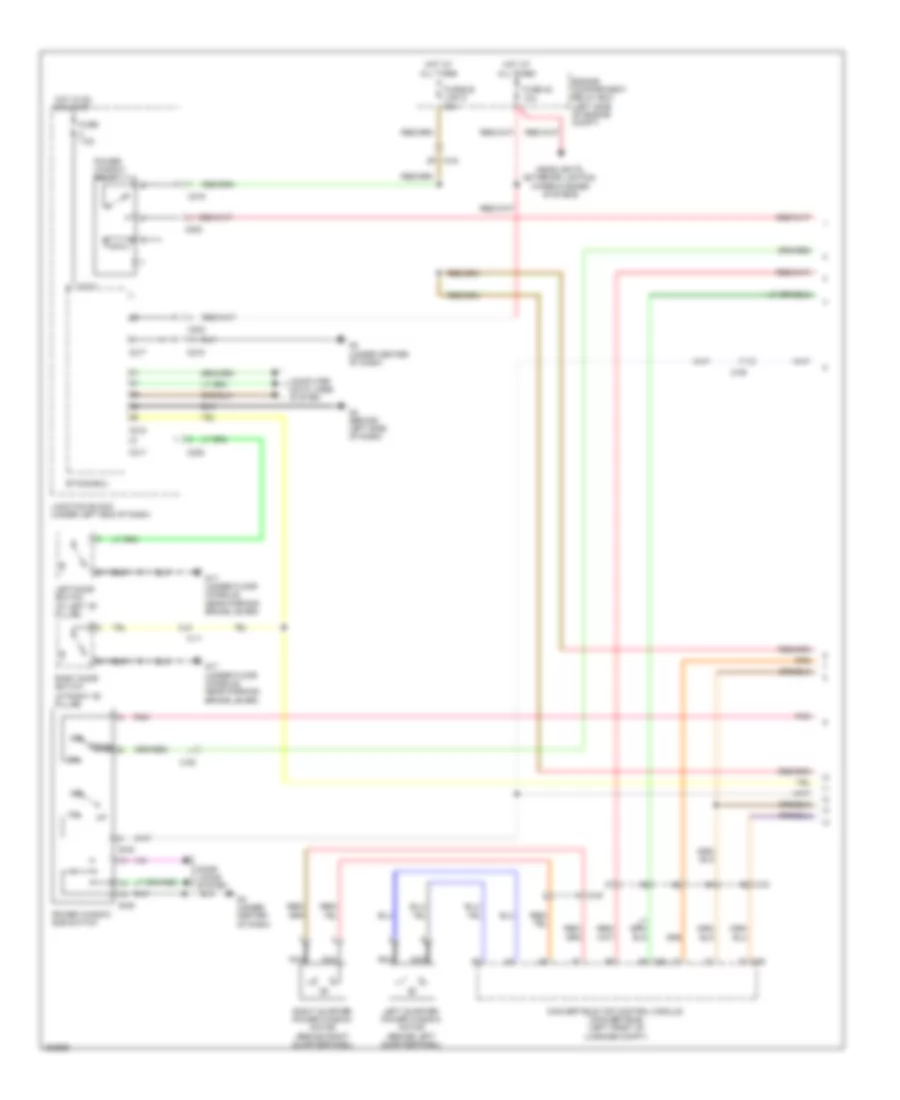
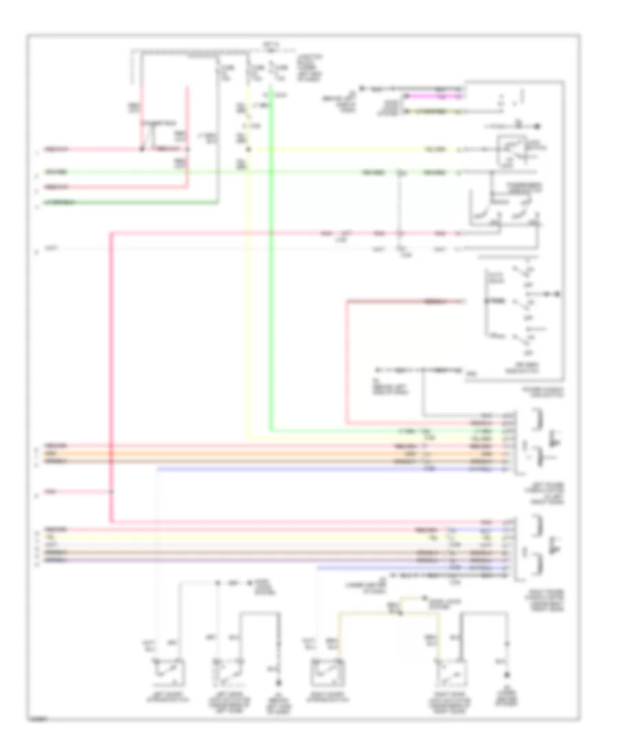
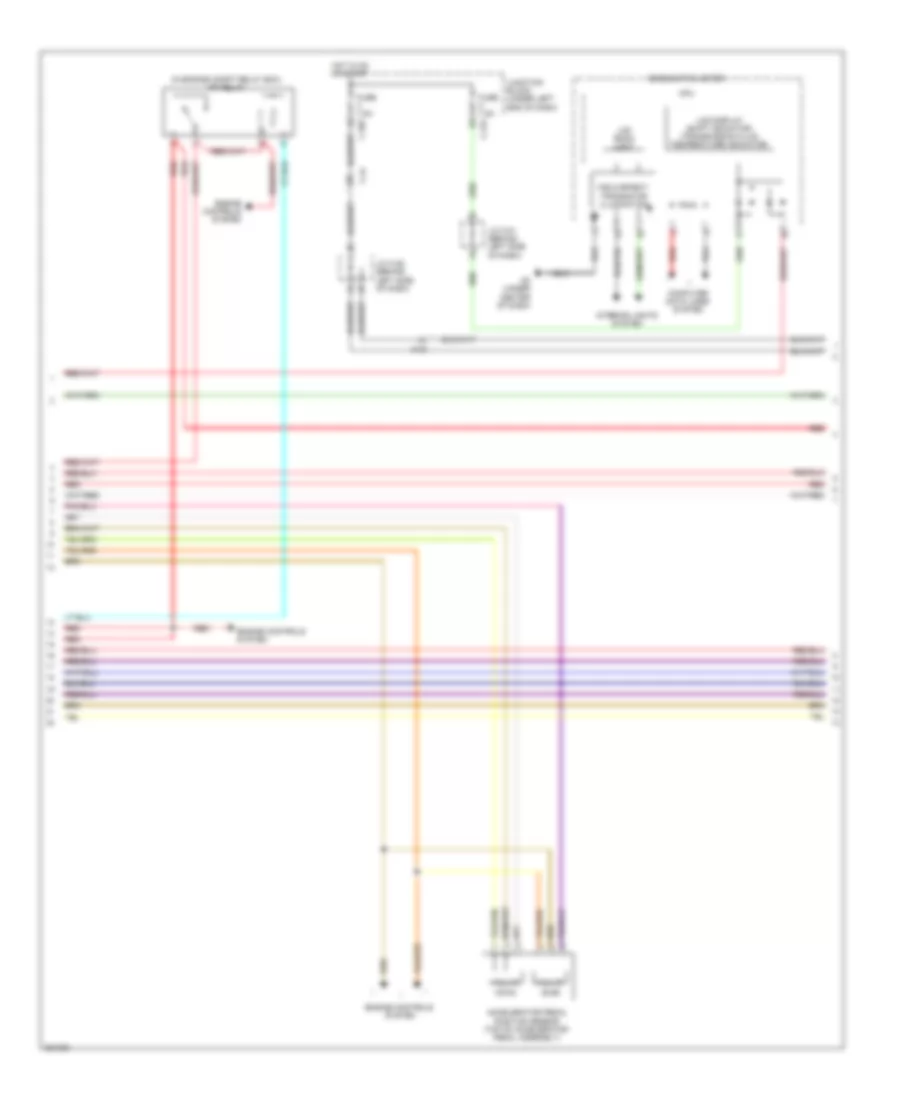
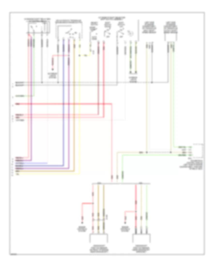
AIR CONDITIONING Automatic A/C Wiring Diagram (1 of 2) for Mitsubishi Eclipse Spyder GT 2012 List of elements for Automatic A/C Wiring Diagram (1 of 2) for Mitsubishi Eclipse Spyder GT 2012: 28 (behind left side of dash) A/c ecu (integral to heater control unit) A/c pressure sensor (right side of engine compt) Air mixing damper control motor & potentiometer (behind right side of dash) Air thermo sensor (behind center of dash, on heater unit) Ambient temperature sensor (near lower left side of radiator) C-15 C-20 C-21 C24 Defogger system Engine compartment relay box (left side of engine compt) Front ecu (in engine compt relay box) Fuse 10a Fuse 15a Fuse 7.5a Heater air intake duct sensor (under left side of dash, in air duct) Hot at all times Hot in acc or on Hot w/ taillight relay energized Illumination light relay Interior lights system Joint connector 1 (behind left side of dash) Joint connector 2 (behind left side of dash) Mode selection damper control motor & potentiometer (behind left side of dash) Nca Outside/inside air selection damper control motor (behind right side of dash, on hvac unit) Red Automatic A/C Wiring Diagram (2 of 2) for Mitsubishi Eclipse Spyder GT 2012 List of elements for Automatic A/C Wiring Diagram (2 of 2) for Mitsubishi Eclipse Spyder GT 2012: 44 (at left rear of engine compt, under relay box) g12 A-15 A-22 A/c compressor assembly A/c compressor clutch A/c compressor clutch relay (in engine compt relay box) A/c refrigerant temperature switch A22-1 B18 B20 B21 Blower motor (behind right side of dash, on hvac unit) Blower relay C-203 C-21 C-24 C202 C215 Computer data lines system Condenser fan motor (left front of engine compt) Connector (below left side of dash) Data link Engine compartment relay box (left side of engine compt) Engine controls system Engine coolant temperature sensor (on rear center of engine, near coolant outlet) Fan control module (attached to cooling fan shroud) Fan control relay (in engine compartment relay box) Fuse 10a Fuse 30a Fuse 7.5a Fusible link 2 50a G12 (at left rear of engine compt, under relay box) G4 (behind left side of dash) Hot at all times Hot in on Joint connector 1 (behind left side of dash) Joint connector 3 (behind left side of dash) Junction block (under left end of dash) Nca Off Power transistor (behind right side of dash) Powertrain control module (a/t) engine control module (m/t) (left side of engine compt, forward of relay box) Radiator fan motor (left front of engine compt) Red Manual A/C Wiring Diagram (1 of 2) for Mitsubishi Eclipse Spyder GT 2012 List of elements for Manual A/C Wiring Diagram (1 of 2) for Mitsubishi Eclipse Spyder GT 2012: 45 (at left rear of engine compartment, under relay box) g12 (behind left side of dash) joint connector 1 (in engine compt relay box) front ecu (left front of engine compt) condenser fan motor A-15 A/c ecu (integral to heater control unit) A/c pressure sensor (right side of engine compt) Air mixing damper control motor & potentiometer (behind right side of dash) Air thermo sensor (behind center of dash, on heater unit) Ambient temperature sensor (near lower left side of radiator) C-203 C-21 C-24 C14 C19 C24 Condenser fan relay (left front of engine compt, in relay box) Defogger system Engine compartment relay box (left side of engine compt) Fan control relay (in engine compt relay box) Fuse 10a Fuse 15a Fuse 7.5a Fusible link 2 30a Fusible link 26 20a G12 (at left rear of engine compt, under relay box) G3 (under center of dash) Headlights Hot at all times Hot in acc or on Hot in on Hot w/ taillight relay energized Illumi- nation light relay Interior lights system Joint connector 1 (behind left side of dash) Joint connector 2 (behind left side of dash) Junction block (under left end of dash) Mode selection damper control motor & potentiometer (behind left side of dash) Nca Outside/inside air selection damper control motor (behind right side of dash, on hvac unit) Radiator fan motor (left front of engine compt) Radiator fan relay (left front of engine compt, in relay box) Red W/ discharge type W/ halogen type headlights Manual A/C Wiring Diagram (2 of 2) for Mitsubishi Eclipse Spyder GT 2012 List of elements for Manual A/C Wiring Diagram (2 of 2) for Mitsubishi Eclipse Spyder GT 2012: 33 A-15 A/c compressor assembly A/c compressor clutch A/c compressor clutch relay (in engine compt relay box) A/c refrigerant temperature switch B-18 B-20 B-21 Blower motor (behind right side of dash, on hvac unit) Blower relay Blower switch C-202 C-215 Computer data lines system Connector (below left side of dash) Data link Engine compartment relay box (left side of engine compt) Engine control module (m/t) powertrain control module (a/t) (left side of engine compartment, forward of relay box) Engine controls system Engine coolant temperature sensor (on rear of engine, near coolant outlet) Fuse 10a Fuse 30a Fuse 7.5a G4 (behind left side of dash) Hot at all times Hot in on Joint connector 2 (behind left side of dash) Joint connector 3 (behind left side of dash) Junction block (under left end of dash) Nca Off Red Resistor (behind right side of dash)
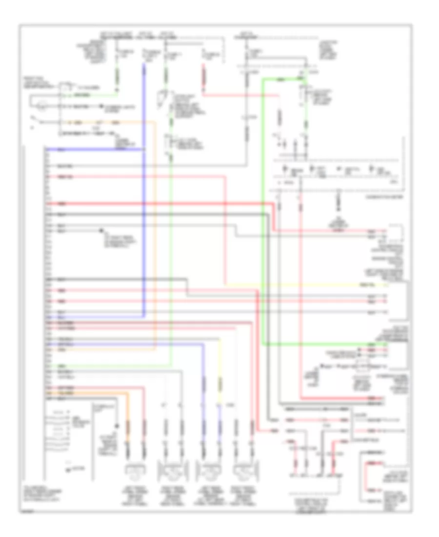
ANTI-LOCK BRAKES Anti-lock Brakes Wiring Diagram for Mitsubishi Eclipse Spyder GT 2012 List of elements for Anti-lock Brakes Wiring Diagram for Mitsubishi Eclipse Spyder GT 2012: 52 Abs solenoid valve Anti lock ind Asc off ind Asc/tcl ind B-18 Brake ind C-203 C-215 C-23 C-24 C-26 Combination meter Computer data lines system Convertible Convertible top control module (left front of luggage compt) Coupe Cpu D-45 Data link connector (below left Engine compartment relay box (left side of engine compt) Front fog lamp switch/ asc off switch Fuse 11 7.5a Fuse 2 7.5a Fuse 20 7.5a Fuse 22 10a Fusible link 3 60a G & yaw rate sensor (under rear of center console) G1 (at right rear of engine compt, on firewall) G3 (under center of dash) Hot at all times Hot in on or start Hot w/ taillight relay energized Hydraulic unit Interior lights system J/c 1 (c-28) (behind left side of dash) J/c 2 (c-01) (behind left side of dash) J/c 3 (c-03) (behind left side of dash) Junction block (under left end of dash) Left front wheel speed sensor (at left front wheel) Left rear wheel speed sensor (at left rear wheel assembly) Motor m Nca Powertrain control module (a/t) engine control module (m/t) (left side of engine compt, forward of relay box) Red Right front wheel speed sensor (at right front wheel) Right rear wheel speed sensor (at right rear wheel) Side of dash) Steering wheel sensor (top of steering column) Stoplight switch (behind left side of dash, on brake pedal support) Tcl/asc-ecu (right rear corner of engine compt, on hydraulic unit) W/ halogen W/ hid
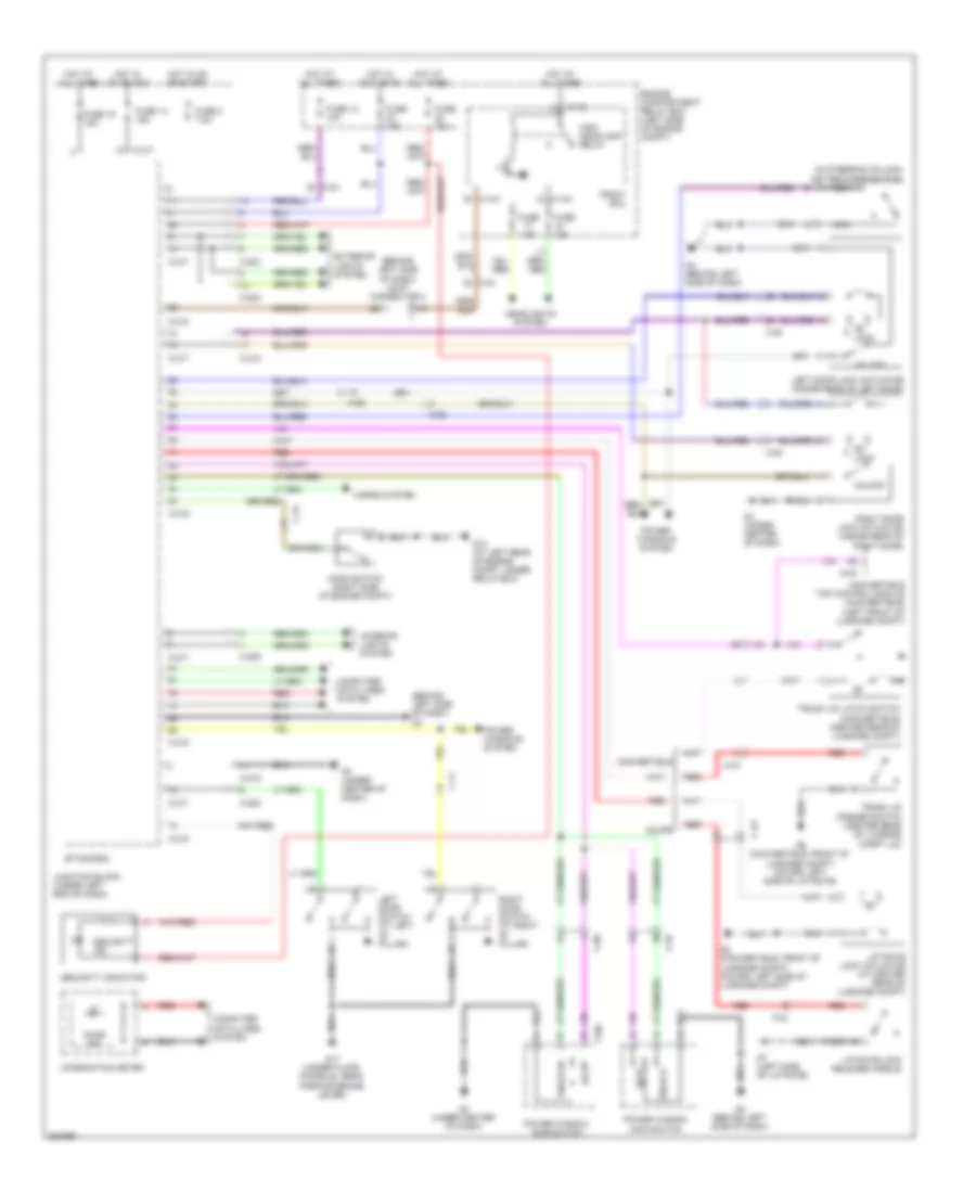
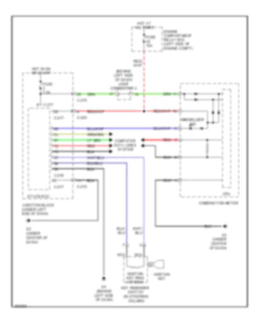
ANTI-THEFT Forced Entry Wiring Diagram for Mitsubishi Eclipse Spyder GT 2012 List of elements for Forced Entry Wiring Diagram for Mitsubishi Eclipse Spyder GT 2012: 70 (behind left side of dash) g4 (behind left side of dash) joint connector 2 (in steering column) key reminder switch A-13x A-14x C-09 C-11 C-203 C-208 C-209 C-215 C-217 C-218 C-219 C-23 C-24 C-25 Combination meter Computer data lines system Convertible Convertible top control module (convertible) (left front of luggage compt) Coupe D-45 Door ind E-06 Engine compartment relay box (left side of engine compt) Etacs-ecu Exterior lights system F-02 Front ecu Fuse 10a Fuse 14 10a Fuse 14 15a Fuse 15 15a Fuse 15a Fuse 2 7.5a G12 (at left rear of engine compt, under relay box) G17 (under floor console, near parking brake lever) G3 (under center of dash) G4 (behind left side of dash) G6 (convertible: front of luggage compt) (coupe: left side of liftgate) G7 (left side of liftgate) G8 (convertible: front of luggage compt) (coupe: left side of luggage compt) Headlights system High headlamp relay Hood switch (right side of engine compt) Horns system Hot at all times Hot in acc or on Hot in on or acc Hot in on or start Interior lights system Junction block (under left end of dash) Left door lock actuator (inside rear of left door) Left door switch (at left "b" pillar) Liftgate lock actuator (at center rear of luggage compt) Liftgate lock release handle Lock Nca Power window main switch Power window sub switch Power windows system Red Right door lock actuator (inside rear of right door) Right door switch (at right "b" pillar) Security ind Security indicator Trunk lid latch switch (convertible) (center rear of luggage compt) Trunk lid opener switch (center rear of luggage compt lid) Unlock Immobilizer Wiring Diagram for Mitsubishi Eclipse Spyder GT 2012 List of elements for Immobilizer Wiring Diagram for Mitsubishi Eclipse Spyder GT 2012: 23 (behind left side of dash) joint connector 2 C-203 C-215 C-217 C-218 Combination meter Computer data lines system Cpu Engine compartment relay box (left side of engine compt) Etacs-ecu Fuse 10a Fuse 7.5a G3 (under center of dash) G4 (behind left side of dash) Hot at all times Hot in on or start Ignition key Ignition key ring antenna Immobilizer ind Junction block (under left end of dash) Key reminder switch (in steering column) Nca Red
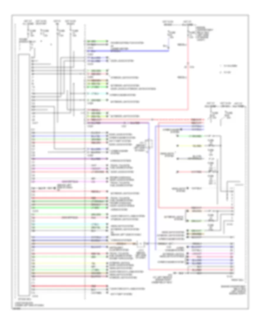
BODY CONTROL MODULES Body Control Modules Wiring Diagram for Mitsubishi Eclipse Spyder GT 2012 List of elements for Body Control Modules Wiring Diagram for Mitsubishi Eclipse Spyder GT 2012: 55 (behind left side of dash) g4 (convertible) A-13x A-14x All times Anti-theft system C-203 C-208 C-209 C-215 C-217 C-218 C-219 C-24 Computer data lines system Door locks & interior lights systems Door locks system Engine compartment relay box (left side of engine compt) Etacs- ecu Exterior lights & headlights systems Exterior lights system Front ecu Fuse 10a Fuse 10a 20a Fuse 15a Fuse 30a Fuse 7.5a G12 (at left rear of engine compt, under relay box) G3 (under center of dash) G4 (behind left side of dash) Headlights system Horns system Hot at Hot in Hot in on Instrument cluster system Interior lights & door locks systems Interior lights system J/c 1 (behind left side of dash) J/c 2 (behind left side of dash) Junction block (under left end of dash) Or acc Or start Pnk Power distribution system Power window relay Power windows & door locks systems Red Trunk, tailgate, fuel doors system Trunk, tailgate, fuel doors system power tops system W/ halogen W/ hid Warning systems Wiper/ washer system Wiper/washer system
COMPUTER DATA LINES Computer Data Lines Wiring Diagram for Mitsubishi Eclipse Spyder GT 2012 List of elements for Computer Data Lines Wiring Diagram for Mitsubishi Eclipse Spyder GT 2012: 37 (under center of dash) g3 A-14x A/c ecu (integral to heater control unit) Automatic a/c B-18 C-123 C-14 C-15 C-21 C-215 C-218 C-23 C-24 C-27 Column switch Combination meter Convertible Convertible top control module (left front of luggage compt) Coupe D-29 D-45 Data link connector (below left side of dash) Engine control module (m/t) powertrain control module (a/t) (left side of engine compt, forward of relay box) Etacs-ecu Front ecu (in engine compt relay box) Fuse 15 15a Hot at all times Joint connector 2 (behind left side of dash) Joint connector 3 (behind left side of dash) Junction block (under left end of dash) Manual a/c Red Srs-ecu (behind lower center of dash, near center reinforcement) Steering wheel sensor (top of steering column) Sunroof motor assembly (on front center of roof) Tcl/asc ecu (right rear corner of engine compt, on hydraulic unit) Tpms receiver (under center of dash)
COOLING FAN Cooling Fan Wiring Diagram for Mitsubishi Eclipse Spyder GT 2012 List of elements for Cooling Fan Wiring Diagram for Mitsubishi Eclipse Spyder GT 2012: 39 (2.4l) (3.8l) (at left rear of engine compat, under relay box) g12 (at left rear of engine compt, under relay box) g12 2.4l 3.8l A-15 A-22 A-22-1 B-18 B-20 B-21 C-203 C-24 Computer data lines system Condenser fan motor (left front of engine compt) Condenser fan motor (m/t: left front of engine compt) Condenser fan relay (left front of engine compt, in relay box) Engine compartment relay box (left side of engine compt) Engine control module (m/t) powertrain control module (a/t) (left side of engine compt, forward of relay box) Engine controls system Engine coolant temperature sensor (2.4l: on rear of engine, near coolant outlet 3.8l: on rear center of engine, near coolant outlet) Fan control module (attached to cooling fan shroud) Fan control relay (in engine compartment relay box) Fan control relay (in engine compt relay box) Fuse 20a Fuse 7.5a Fusible link 2 30a 50a Fusible link 26 20a G12 (at left rear of engine compt, under relay box) Hot at all times Hot in on Joint connector 1 (behind left side of dash) Junction block (under left end of dash) Mfi relay (in eng compt relay box) Nca Power distribution system Radiator fan motor (left front of engine compt) Radiator fan relay (left front of engine compt, in relay box) Red
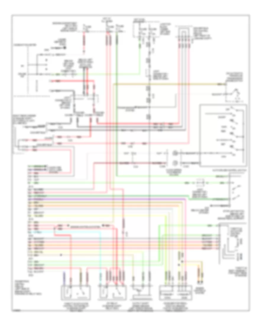
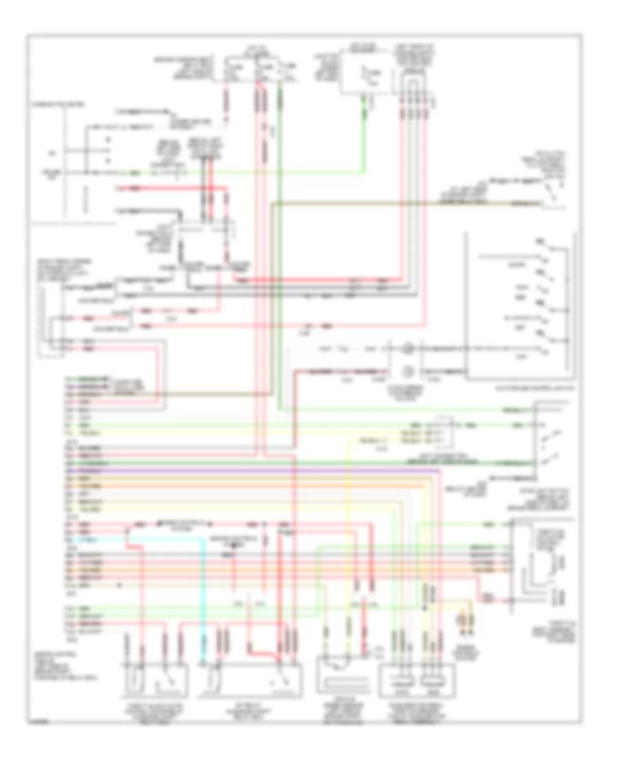
CRUISE CONTROL Cruise Control Wiring Diagram, A/T for Mitsubishi Eclipse Spyder GT 2012 List of elements for Cruise Control Wiring Diagram, A/T for Mitsubishi Eclipse Spyder GT 2012: 57 (behind left side of dash) joint connector 2 (below left side of dash) data link connector (main) (on automatic transaxle) transmission range switch (right rear corner of engine compt, on hydraulic unit) tcl/abs ecu (sub) (under center of dash) g3 A-15 Accelerator pedal position sensor (top of accelerator pedal assembly) Auto-cruise control switch B-18 B-19 B-20 B-21 B-22 C-203 C-215 C-23 C-24 C-26 C-303 C-306 Can Clock spring (in steering column) Combination meter Computer data lines system Conver- tible Convertible Convertible top control module (left front of luggage compt) d-45 Coupe Cruise ind Engine compartment relay box (left side of engine compt) Engine controls system Fuse 10a Fuse 20a Fuse 7.5a G16 (below center of dash) Gnd Hall ic Hot at all times Hot in on or start Joint connector 1 (behind left side of dash) Joint connector 3 (behind left side of dash) Junction block (under left end of dash) Mfi relay (in engine compt relay box) Off On/off Output shaft speed sensor (left side of engine compt, on transaxle) Powertrain control module (left side of engine compt, forward of relay box) Red Res Set Stoplight switch (behind left side of dash, on brake pedal support) Throttle actuator control motor Throttle actuator control motor relay (in engine compt relay box) Throttle body assembly (top right rear of engine) Transmissions system Cruise Control Wiring Diagram, M/T for Mitsubishi Eclipse Spyder GT 2012 List of elements for Cruise Control Wiring Diagram, M/T for Mitsubishi Eclipse Spyder GT 2012: 58 (behind left side of dash) joint connector 2 (below left side of dash) data link connector (left front of luggage compt) convertible top control module (main) (on clutch pedal support) clutch pedal position switch (right rear corner of engine compt, on hydraulic unit) tcl/abs ecu (sub) 2.4l 3.8l A-15 Accelerator pedal position sensor (top of accelerator pedal assembly) Auto-cruise control switch B-18 B-19 B-20 B-21 B-22 C-215 C-23 C-24 C-26 C-303 C-306 Can Clock spring (in steering column) Combination meter Computer data lines system Conver- tible Convertible Coupe Cruise ind D-45 Engine compartment relay box (left side of engine compt) Engine control module (left side of engine compt, forward of relay box) Engine controls system Fuse 10a Fuse 20a Fuse 7.5a G12 (at left rear of engine compt, under relay box) G16 (below center of dash) G3 (under center of dash) Hall ic Hot at all times Hot in on or start Joint connector 1 (behind left side of dash) Joint connector 3 (behind left side of dash) Junction block (under left end of dash) Mfi relay (in engine compt relay box) Off On/off Red Res Set Stoplight switch (behind left side of dash, on brake pedal support) Throttle actuator control motor Throttle actuator control motor relay (in engine compt relay box) Throttle body assembly (top right rear of engine) Vehicle speed sensor (left side of engine compt, on transaxle)
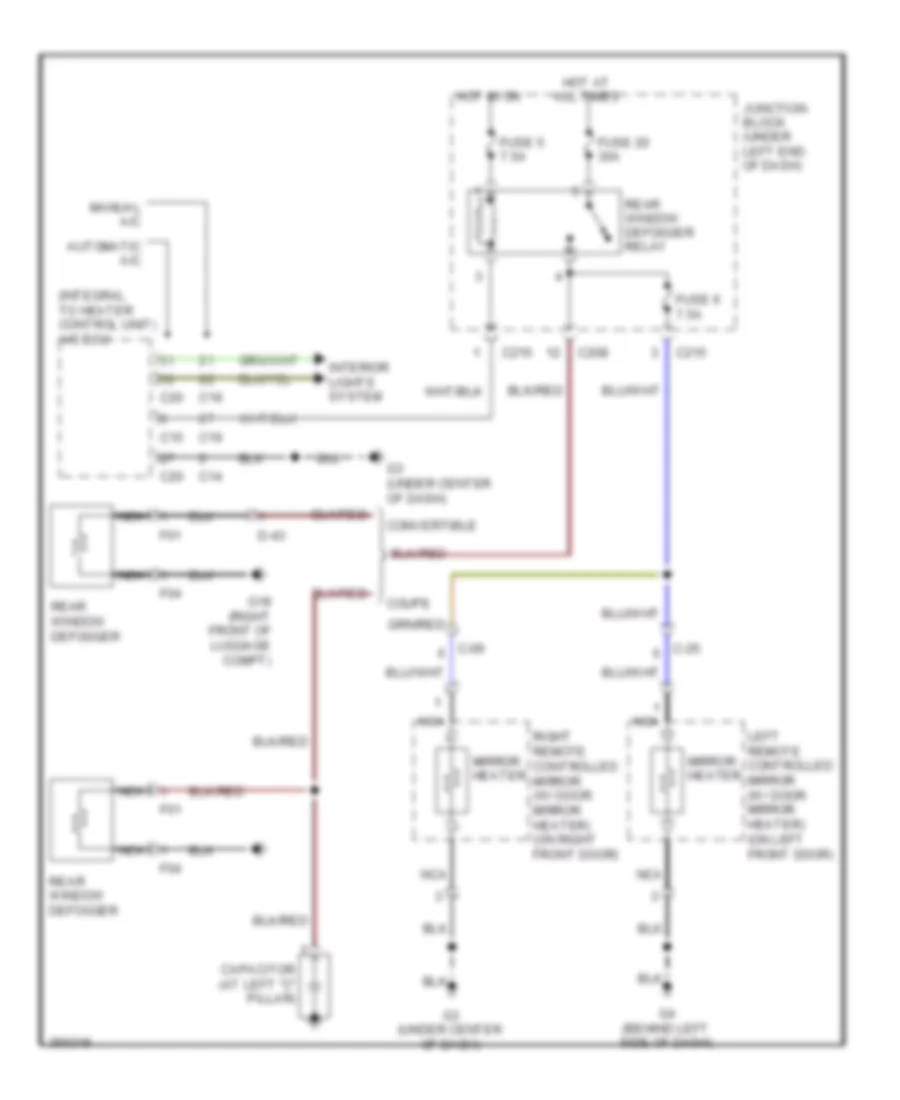
DEFOGGERS Defoggers Wiring Diagram for Mitsubishi Eclipse Spyder GT 2012 List of elements for Defoggers Wiring Diagram for Mitsubishi Eclipse Spyder GT 2012: 33 (integral to heater control unit) a/c ecu Automatic a/c C-09 C-25 C14 C15 C19 C20 C208 C215 Capacitor (at left "c" pillar) Convertible Coupe D-43 F01 F04 Fuse 20 30a Fuse 5 7.5a Fuse 6 7.5a G18 (right front of luggage compt) G3 (under center of dash) G4 (behind left side of dash) Hot at all times Hot in on Interior lights system Junction block (under left end of dash) Left remote controlled mirror (w/ door mirror heater) (on left front door) Manual a/c Mirror heater Nca Rear window defogger Rear window defogger relay Right remote controlled mirror (w/ door mirror heater) (on right front door)
ENGINE PERFORMANCE
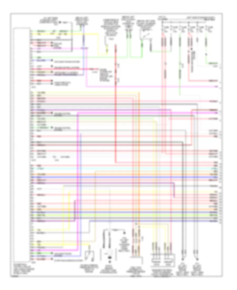
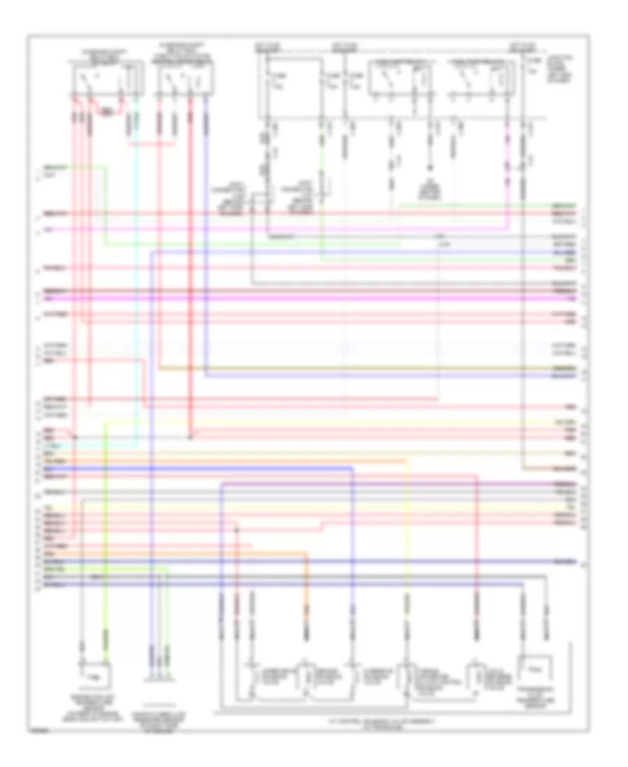
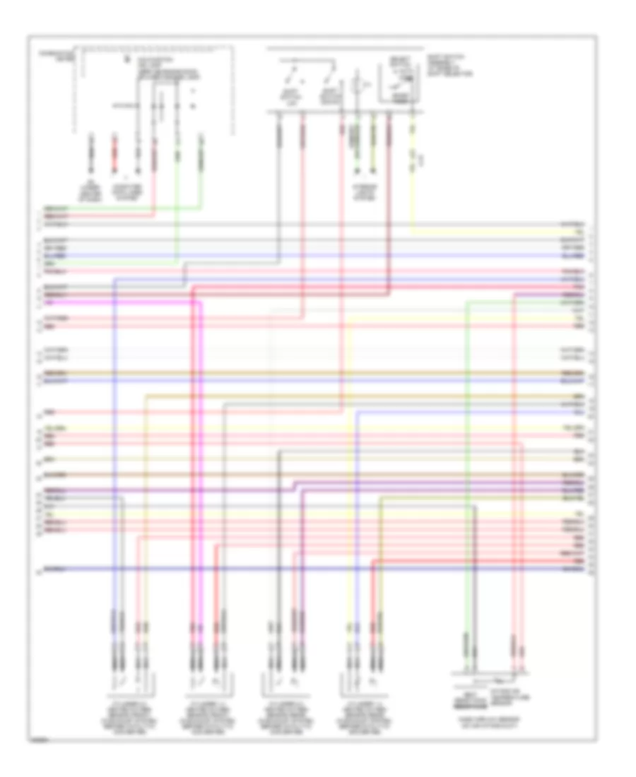
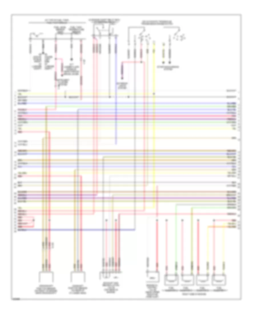
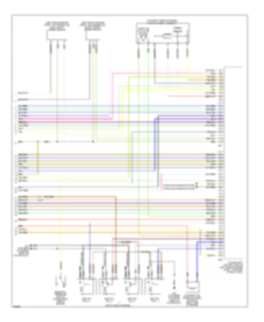
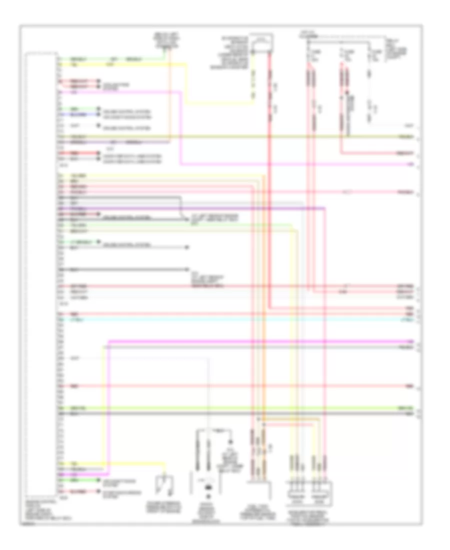
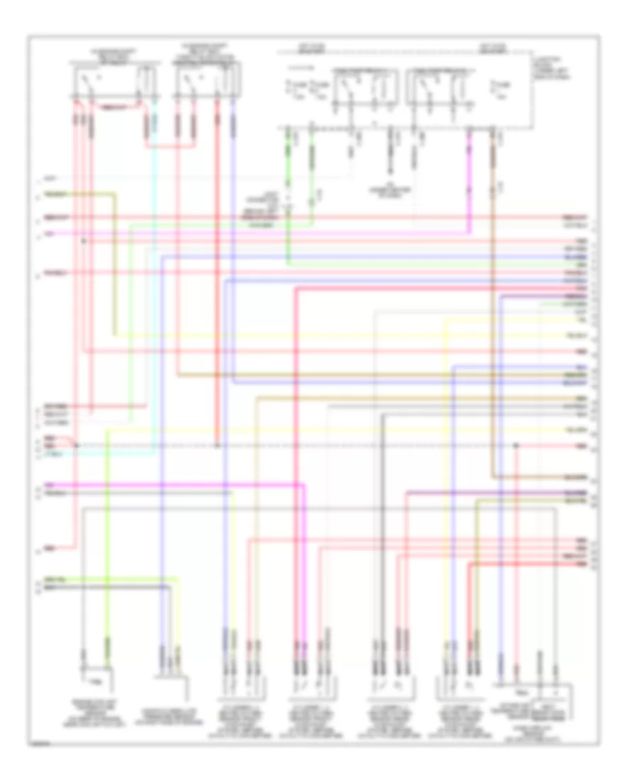
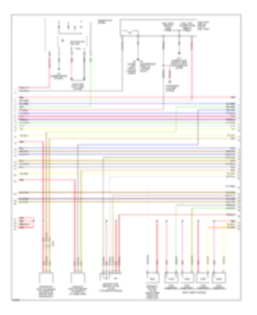
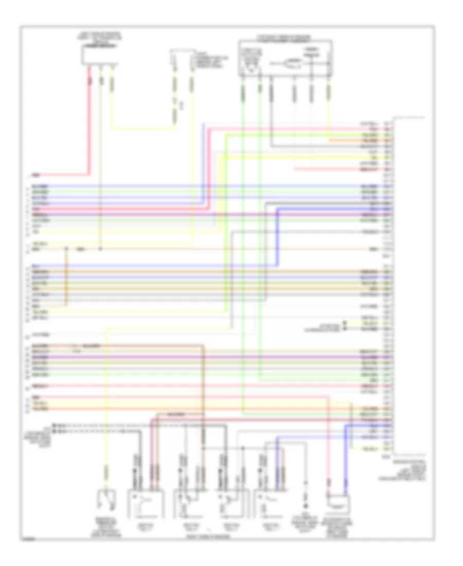
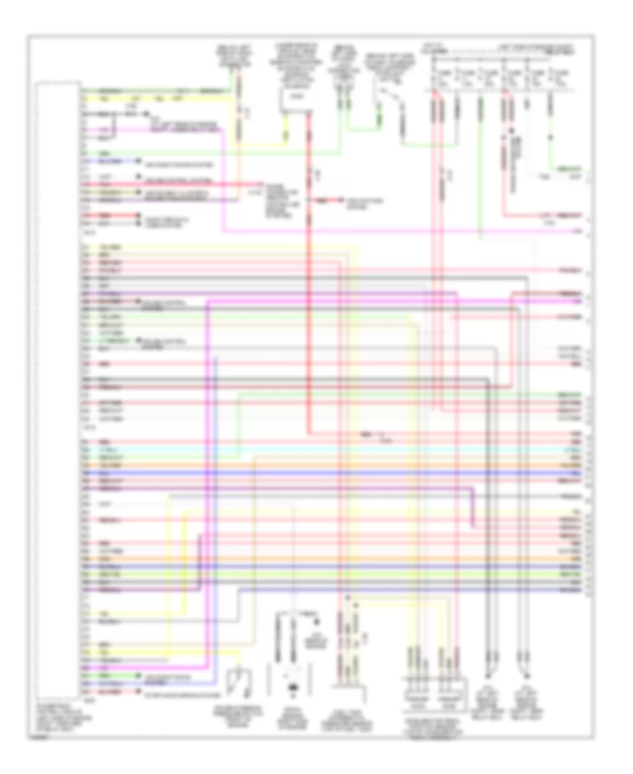
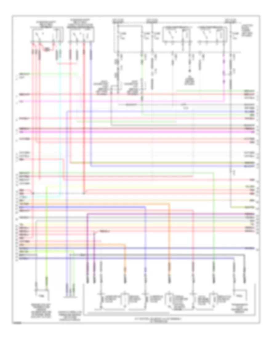
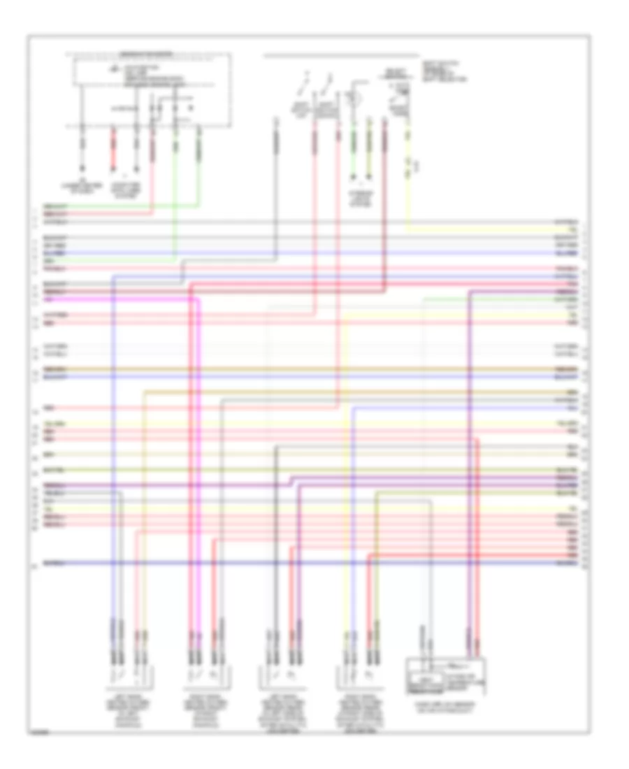
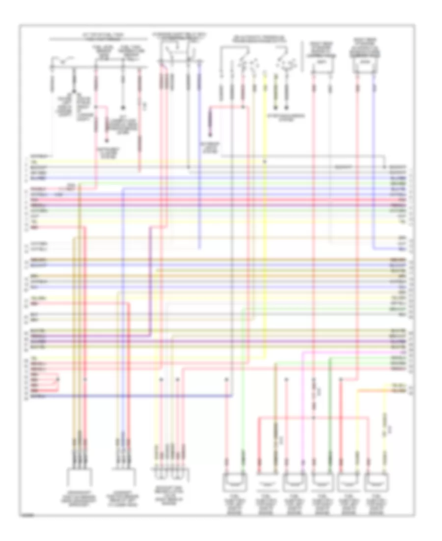
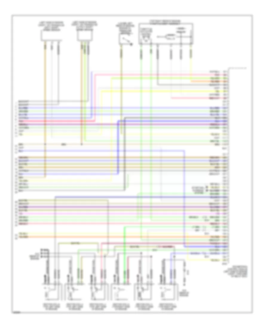
2.4L 2.4L, Engine Performance Wiring Diagram, A/T (1 of 5) for Mitsubishi Eclipse Spyder GT 2012 List of elements for 2.4L, Engine Performance Wiring Diagram, A/T (1 of 5) for Mitsubishi Eclipse Spyder GT 2012: 41 (at left rear of engine compt, under relay box) g12 (behind left side of dash) joint connector c-28 (behind left side of dash, on brake pedal support) stoplight switch (below left side of dash) data link connector (left side of engine compt) relay box (main) (sub) (under rear of vehicle, near evaporative emission canister) evaporative emission ventilation solenoid A-15 Accelerator pedal position sensor (top of accelerator pedal assembly) Air conditioning system B-18 B-19 B-20 C-140 C-21 C-24 C-26 Computer data lines system Cooling fans system Cruise control system Fuel tank differential pressure sensor (top of fuel tank) Fuse 10a Fuse 15a Fuse 20a Fuse 7.5a G12 (at left rear of engine compt, under relay box) G13 (at left rear of engine compt, near relay box) G14 (at left rear of engine compt, near relay box) Hall ic Hot at all times Instrument cluster & power tops systems Knock sensor (on right side of engine block) Nca Pnk Power distribution system Power steering pressure switch (front of engine) Powertrain control module (left side of engine compt, forward of relay box) Red Spare connector (remote controlled engine starter) Starting/charging system 2.4L, Engine Performance Wiring Diagram, A/T (2 of 5) for Mitsubishi Eclipse Spyder GT 2012 List of elements for 2.4L, Engine Performance Wiring Diagram, A/T (2 of 5) for Mitsubishi Eclipse Spyder GT 2012: 27 (in engine compt relay box) mfi relay (in engine compt relay box) throttle actuator control motor relay A-15 A/t control solenoid valve assembly (in transaxle) C-203 C-208 C-215 C-24 Engine coolant temperature sensor (on rear of engine, near coolant outlet) Fuel pump relay 1 Fuel pump relay 2 Fuse 10a Fuse 7.5a G3 (under center of dash) Hot in on or start Joint connector c-01 (behind left side of dash) Joint connector c-28 (behind left side of dash) Junction block (under left end of dash) Low & reverse solenoid valve Manifold absolute pressure sensor (on right side of engine) Nca Overdrive solenoid valve Red Second solenoid valve Torque converter clutch control solenoid valve Transmission fluid temperature sensor Under drive solenoid valve 2.4L, Engine Performance Wiring Diagram, A/T (3 of 5) for Mitsubishi Eclipse Spyder GT 2012 List of elements for 2.4L, Engine Performance Wiring Diagram, A/T (3 of 5) for Mitsubishi Eclipse Spyder GT 2012: 24 (up) A-15 Auto mode Combination meter Computer data lines system Cylinder 1,4 heated oxygen sensor (front) (in exhaust system, before catalytic converter) Cylinder 1,4 heated oxygen sensor (rear) (in exhaust system, before catalytic converter) Cylinder 2,3 heated oxygen sensor (front) (in exhaust system, before catalytic converter) Cylinder 2,3 heated oxygen sensor (rear) (in exhaust system, before catalytic converter) G3 (under center of dash) Heat sensitizing resistance Ill Intake air temperature sensor Interior lights system Malfunction ind lamp (service engine soon or check engine lamp) Mass airflow sensor (on air intake duct) Nca Pnk Red Select switch Shift switch Shift switch (down) Shift switch assembly (at base of shift selector) Sport mode 2.4L, Engine Performance Wiring Diagram, A/T (4 of 5) for Mitsubishi Eclipse Spyder GT 2012 List of elements for 2.4L, Engine Performance Wiring Diagram, A/T (4 of 5) for Mitsubishi Eclipse Spyder GT 2012: 24 (at top of fuel tank) fuel pump module (in engine compt relay box) a/t control relay (on automatic transaxle) transmission range switch (right side of engine) B-125 C-26 Camshaft position sensor (on rear of cylinder head) Crankshaft position sensor (on front of engine, near crankshaft) Engine oil control valve (near upper radiator hose inlet) Exhaust gas recirculation valve (top rear of engine) Exterior lights system Fuel injector 1 Fuel injector 2 Fuel injector 3 Fuel injector 4 Fuel level sensor (main) Fuel tank temperature sensor G17 (under floor console, near parking brake lever) G6 (conve- rtible) (front of luggage compt) G8 (coupe) (left side of luggage compt) Instrument cluster system Pnk Red Starting/charging system 2.4L, Engine Performance Wiring Diagram, A/T (5 of 5) for Mitsubishi Eclipse Spyder GT 2012 List of elements for 2.4L, Engine Performance Wiring Diagram, A/T (5 of 5) for Mitsubishi Eclipse Spyder GT 2012: 24 (left side of engine compt, on transaxle) input shaft speed sensor (left side of engine compt, on transaxle) output shaft speed sensor (main) (right side of engine) (sub) (top right rear of engine) throttle body assembly B-21 B-22 C-15 Engine oil pressure switch (lower right side of engine) Evaporative emission purge solenoid (right side of engine) G10 (top rear of engine, near air intake duct) Hall ic Ignition coil 1 Ignition coil 2 Ignition coil 3 Ignition coil 4 Nca Pnk Powertrain control module (left side of engine compt, forward of relay box) Red Spark plug Starting/charging system Throttle actuator control motor 2.4L, Engine Performance Wiring Diagram, M/T (1 of 4) for Mitsubishi Eclipse Spyder GT 2012 List of elements for 2.4L, Engine Performance Wiring Diagram, M/T (1 of 4) for Mitsubishi Eclipse Spyder GT 2012: 33 (at left rear of engine compt, near relay box) g14 (below left side of dash) data link connector (main) (sub) A-15 Accelerator pedal position sensor (top of accelerator pedal assembly) Air conditioning system B-18 B-19 B-20 C-21 C-24 C-26 Computer data lines system Cooling fans system Cruise control system Engine control module (left side of engine compt, forward of relay box) Evaporative emission ventilation solenoid (under rear of vehicle, near evaporative emission canister) Fuel tank differential pressure sensor (top of fuel tank) Fuse 10a Fuse 15a Fuse 20a G12 (at left rear of engine compt, under relay box) G13 (at left rear of engine compt, near relay box) Hall ic Hot at all times Knock sensor (on right side of engine block) Nca Power distribution system Power steering pressure switch (front of engine) Red Relay box (left side of engine compt) Starting/charging system 2.4L, Engine Performance Wiring Diagram, M/T (2 of 4) for Mitsubishi Eclipse Spyder GT 2012 List of elements for 2.4L, Engine Performance Wiring Diagram, M/T (2 of 4) for Mitsubishi Eclipse Spyder GT 2012: 26 (in engine compt relay box) mfi relay (in engine compt relay box) throttle actuator control motor relay C-203 C-208 C-215 C-24 Cylinder 1, 4 heated oxygen sensor (front) (in exhaust system, before catalytic converter) Cylinder 1, 4 heated oxygen sensor (rear) (in exhaust system, before catalytic converter) Cylinder 2, 3 heated oxygen sensor (front) (in exhaust system, before catalytic converter) Cylinder 2, 3 heated oxygen sensor (rear) (in exhaust system, before catalytic converter) Engine coolant temperature sensor (on rear of engine, near coolant outlet) Fuel pump relay 1 Fuel pump relay 2 Fuse 10a Fuse 7.5a G3 (under center of dash) Heat sensitizing resistance Hot in on or start Intake air temperature sensor Joint connector c-01 (behind left side of dash) Junction block (under left end of dash) Manifold absolute pressure sensor (on right side of engine) Mass airflow sensor (on air intake duct) Nca Pnk Red 2.4L, Engine Performance Wiring Diagram, M/T (3 of 4) for Mitsubishi Eclipse Spyder GT 2012 List of elements for 2.4L, Engine Performance Wiring Diagram, M/T (3 of 4) for Mitsubishi Eclipse Spyder GT 2012: 23 (right side of engine) B125 Camshaft position sensor (on rear of cylinder head) Combination meter Computer data lines system Crankshaft position sensor (on front of engine, near crankshaft) Engine oil control valve (near upper radiator hose inlet) Exhaust gas recirculation valve (top rear of engine) Fuel injector 1 Fuel injector 2 Fuel injector 3 Fuel injector 4 Fuel level sensor (main) Fuel pump module (top of fuel tank) Fuel tank temperature sensor G17 (under floor console, near parking brake lever) G3 (under center of dash) G6 (convertible) (front of luggage compt) G8 (coupe) (left side of luggage compt) Instrument cluster system Malfunction ind lamp Pnk Red 2.4L, Engine Performance Wiring Diagram, M/T (4 of 4) for Mitsubishi Eclipse Spyder GT 2012 List of elements for 2.4L, Engine Performance Wiring Diagram, M/T (4 of 4) for Mitsubishi Eclipse Spyder GT 2012: 24 (left side of engine compt, on transaxle) vehicle speed sensor (main) (right side of engine) (sub) (top right rear of engine) throttle body assembly A-15 B-21 B-22 Engine control module (left side of engine compt, forward of relay box) Engine oil pressure switch (lower right side of engine) Evaporative emission purge solenoid (right side of engine) G10 (top rear of engine, near air intake duct) Hall ic Ignition coil 1 Ignition coil 2 Ignition coil 3 Ignition coil 4 Joint connector c-28 (behind left side of dash) Nca Plug spark Pnk Red Starting/ charging system Throttle actuator control motor
3.8L 3.8L, Engine Performance Wiring Diagram (1 of 5) for Mitsubishi Eclipse Spyder GT 2012 List of elements for 3.8L, Engine Performance Wiring Diagram (1 of 5) for Mitsubishi Eclipse Spyder GT 2012: 41 (behind left side of dash) joint connector c-28 (behind left side of dash, on brake pedal support) stoplight switch (below left side of dash) data link connector (left side of engine compt) relay box (main) (remote controlled engine starter) (sub) (under rear of vehicle, near evaporative emission canister) evaporative emission ventilation solenoid A-15 Accelerator pedal position sensor (top of accelerator pedal assembly) Air conditioning system B-18 B-19 B-20 C-21 C-24 C-26 Computer data lines system Cooling fans system Cruise control system Fuel tank differential pressure sensor (top of fuel tank) Fuse 10a Fuse 15a Fuse 20a Fuse 7.5a G10 (rear of engine) G12 (at left rear of engine compt, under relay box) G13 (at left rear of engine compt, near relay box) G14 (at left rear of engine compt, near relay box) Hall ic Hot at all times Instrument cluster & power tops systems Knock sensor (right side of engine) Nca Pnk Power distribution system Power steering pressure switch (front of engine) Powertrain control module (left side of engine compt, forward of relay box) Red Spare connector c-140 Starting/charging system 3.8L, Engine Performance Wiring Diagram (2 of 5) for Mitsubishi Eclipse Spyder GT 2012 List of elements for 3.8L, Engine Performance Wiring Diagram (2 of 5) for Mitsubishi Eclipse Spyder GT 2012: 28 (in engine compt relay box) mfi relay (in engine compt relay box) throttle actuator control motor relay A-15 A/t control solenoid valve assembly (in transaxle) C-203 C-208 C-215 C-24 Engine coolant temperature sensor (on rear center of engine, near coolant outlet) Fuel pump relay 1 Fuel pump relay 2 Fuse 10a Fuse 7.5a G3 (under center of dash) Hot in on or start Joint connector c-01 (behind left side of dash) Joint connector c-28 (behind left side of dash) Junction block (under left end of dash) Low & reverse solenoid valve Manifold absolute pressure sensor (on intake manifold plenum) Nca Overdrive solenoid valve Red Reduction solenoid valve Second solenoid valve Torque converter clutch control solenoid valve Transmission fluid temperature sensor Under drive solenoid valve 3.8L, Engine Performance Wiring Diagram (3 of 5) for Mitsubishi Eclipse Spyder GT 2012 List of elements for 3.8L, Engine Performance Wiring Diagram (3 of 5) for Mitsubishi Eclipse Spyder GT 2012: 23 A-15 Auto mode Combination meter Computer data lines system G3 (under center of dash) Heat sensitizing resistance Ill Intake air temperature sensor Interior lights system Left bank heated oxygen sensor (front) (in left exhaust manifold) Left bank heated oxygen sensor (rear) (in left side of exhaust system, after catalytic converter) Malfunction ind lamp (service engine soon or check engine lamp) Mass airflow sensor (on air intake duct) Nca Pnk Red Right bank heated oxygen sensor (front) (in right exhaust manifold) Right bank heated oxygen sensor (rear) (in right side of exhaust system, after catalytic converter) Select switch Shift switch (down) Shift switch (up) Shift switch assembly (at base of shift selector) Sport mode 3.8L, Engine Performance Wiring Diagram (4 of 5) for Mitsubishi Eclipse Spyder GT 2012 List of elements for 3.8L, Engine Performance Wiring Diagram (4 of 5) for Mitsubishi Eclipse Spyder GT 2012: 27 (at top of fuel tank) fuel pump module (in engine compt relay box) a/t control relay (on automatic transaxle) transmission range switch (right rear of engine) engine oil control valve (right rear of engine) evaporative emission purge solenoid valve B-31 C-26 Camshaft position sensor (rear of left cylinder head) Crankshaft position sensor (near crankshaft sprocket) Exhaust gas recirculation valve (right rear of engine) Exterior lights system Fuel injector 1 (top right side of engine) Fuel injector 2 (top left side of engine) Fuel injector 3 (top right side of engine) Fuel injector 4 (top left side of engine) Fuel injector 5 (top right side of engine) Fuel injector 6 (top left side of engine) Fuel level sensor (main) Fuel tank temperature sensor G17 (under floor console, near parking brake lever) G6 (conve- rtible) (front of luggage compt) G8 (coupe) (left side of luggage compt) Instrument cluster system Nca Pnk Red Starting/charging system 3.8L, Engine Performance Wiring Diagram (5 of 5) for Mitsubishi Eclipse Spyder GT 2012 List of elements for 3.8L, Engine Performance Wiring Diagram (5 of 5) for Mitsubishi Eclipse Spyder GT 2012: 23 (left side of engine compt, on transaxle) input shaft speed sensor (left side of engine compt, on transaxle) output shaft speed sensor (lower left rear of engine) engine oil pressure switch (main) (sub) (top right rear of engine) throttle body assembly B-21 B-22 B-31 G10 (rear of engine) Hall ic Ignition coil 1 (top right side of engine) Ignition coil 2 (top left side of engine) Ignition coil 3 (top right side of engine) Ignition coil 4 (top left side of engine) Ignition coil 5 (top right side of engine) Ignition coil 6 (top left side of engine) Nca Pnk Powertrain control module (left side of engine compt, forward of relay box) Spark plug Starting/ charging system Throttle actuator control motor
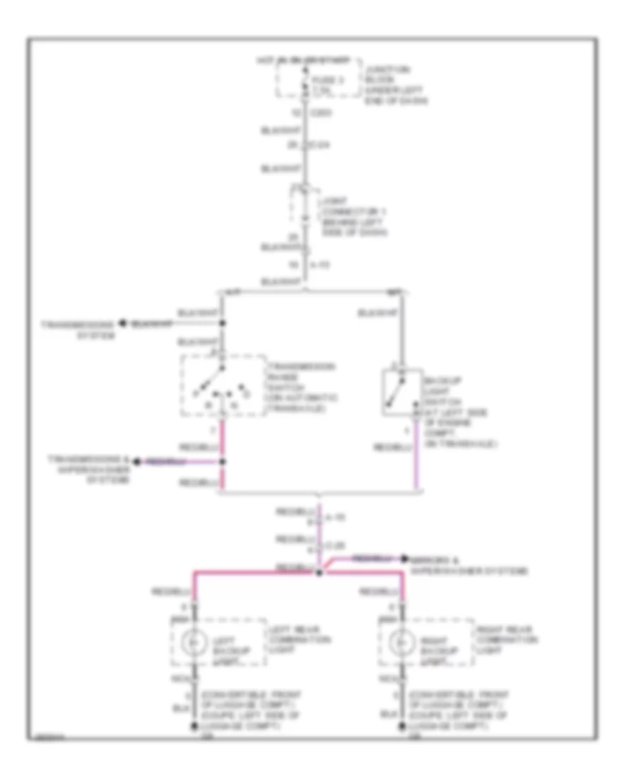
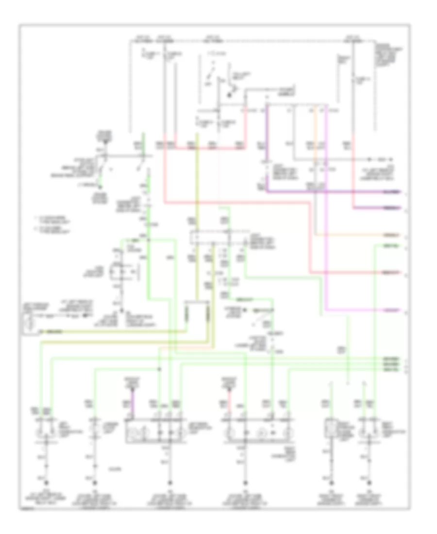
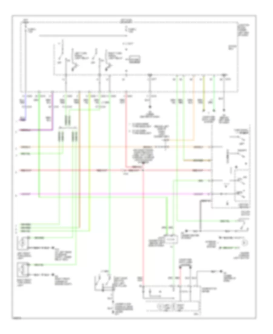
EXTERIOR LIGHTS Backup Lamps Wiring Diagram for Mitsubishi Eclipse Spyder GT 2012 List of elements for Backup Lamps Wiring Diagram for Mitsubishi Eclipse Spyder GT 2012: 22 (convertible: front A-15 A/t Backup light switch (at left side of engine compt, on transaxle) C-24 C-26 C203 Fuse 3 7.5a Hot in on or start Joint connector 1 (behind left side of dash) Junction block (under left end of dash) Left backup light Left rear combination light M/t Mirrors & wiper/washer systems Nca Of luggage compt) (coupe: left side of luggage compt) g8 Right backup light Right rear combination light Transmission range switch (on automatic transaxle) Transmissions & wiper/washer systems Transmissions system Exterior Lamps Wiring Diagram (1 of 2) for Mitsubishi Eclipse Spyder GT 2012 List of elements for Exterior Lamps Wiring Diagram (1 of 2) for Mitsubishi Eclipse Spyder GT 2012: 44 (at left rear of engine compt under relay box) A-13x A-14x Backup lamps circuit C-21 C-24 C-26 C203 C208 Coupe Cruise control system Engine compartment relay box (left side of engine compt) F-02 (coupe) Front ecu Fuse 11 7.5a Fuse 14 10a Fuse 20 7.5a Fuse 21 7.5a Fuse 22 10a G12 G12 (at left rear of engine compt, under relay box) G7 (coupe) (left side of liftgate) G8 (convertible) (front of luggage compt) G8 (coupe: left side of luggage compt) (convertible: front of luggage compt) G9 (right front corner of engine compt) High mounted stoplight Hot at all times Interior lights system Joint connector 1 (behind left side of dash) Junction block (under left end of dash) Left front combination light Left parking/ side marker light Left rear combination light License plate light Nca Off Right front combination light Right parking & side marker light Right rear combination light Stoplight switch (behind left side of dash, on brake pedal support) Taillight relay Type headlight W/ discharge type headlight W/ halogen Exterior Lamps Wiring Diagram (2 of 2) for Mitsubishi Eclipse Spyder GT 2012 List of elements for Exterior Lamps Wiring Diagram (2 of 2) for Mitsubishi Eclipse Spyder GT 2012: 46 (behind left side of dash) joint connector 2 (under floor console, near parking brake lever) g17 Air conditioning, computer data lines, anti-theft, warning, interior lights & sound systems C-24 C203 C208 C215 C217 C218 Column switch Column-ecu Combination meter Computer data lines system Cpu Etacs ecu Fuse 2 7.5a Fuse 5 7.5a G12 (at left rear of engine compt, under relay box) G3 (under center of dash) G4 (behind left side of dash) G9 (right front corner of engine compt) Gnd Hazard warning light switch Head Hot in on Hot in on or start Interior lights system Joint connector 2 (behind left side of dash) Junction block (under left end of dash) Left Left door switch (at left "b" pillar) Left front turn signal light Left turn ind Left turn signal light relay Lighting switch Off Power source Red Right Right front turn signal light Right turn ind Right turn signal light relay Tail Turn signal switch W/ discharge type headlight W/ halogen type headlight
GROUND DISTRIBUTION Ground Distribution Wiring Diagram for Mitsubishi Eclipse Spyder GT 2012 List of elements for Ground Distribution Wiring Diagram for Mitsubishi Eclipse Spyder GT 2012: 59 (2.4l), (3.8l) & (3.8l), (a/t) & (a/t), (coupe) (coupe), (coupe), (coupe), (halogen type) (halogen type), (m/t) (m/t), Accessory socket (battery), stoplight switch & satellite radio tuner Asc off switch Battery Brake fluid level switch, left front combination light & left headlight assembly (discharge type) Condenser fan motor clutch pedal position switch (m/t), knock sensor left front combination light, windshield wiper motor, radiator fan relay left headlight (halogen type), brake fluid level switch fan control module left headlight assembly (discharge type) Convertible top buzzer (convertible), multi-center display unit, accessory socket (acc), inside rear view mirror assembly, remote controlled mirror switch, left remote controlled mirror (w/ door mirror heater), blower motor, blower relay, tpms receiver, a/c-ecu, heated seat switch, front dome light, power window main switch, etacs-ecu, heated seat relay, column switch, key reminder switch, front fog light/asc off switch (discharge type), glove box light, rear dome light left vanity mirror light, right vanity mirror light, key reminder switch, left door lock actuator, hazard warning light switch, left power window motor, accessory socket relay, micro phone switch, hands-free module, Convertible top buzzer (convertible), power window relay, multi-center display unit, accessory socket (acc), inside rear view mirror assembly, remote controlled mirror switch, right remote controlled mirror (w/ door mirror heater), a/c-ecu, tpms receiver, fuel pump relay (1), front dome light, combination meter, blower relay, power window sub switch, data link connector, column switch, srs ecu, front fog light/asc off switch (discharge type), rear dome light key reminder switch, glove box light, etacs-ecu, left vanity mirror light, right vanity mirror light, hazard warning light switch, right door lock actuator, accessory socket relay, audio amplifier, right power window motor, micro phone switch, hands-free module & front fog light switch (halogen type) Engine control module Engine control module clutch pedal position switch front-ecu, windshield wiper motor, left front fog light, Fan control relay Front-ecu, hood switch, left front fog light, Fuel pump module, left door switch, right door switch, left heated seat assembly, seat belt switch (driver side), power seat assembly, occupant classification-ecu & right heated seat assembly G1 (at right rear of engine compt, on firewall) G10 (2.4l: top rear of engine, near air intake duct) (3.8l: rear of engine) G11 (2.4l: lower rear of engine) (3.8l: rear of engine) G12 (at left rear of engine compt, under relay box) G13 (at left rear of engine compt, near relay box) G14 (at left rear of engine compt, near relay box) G15 (near left front shock tower) G16 (below center of dash) G17 (under floor console, near parking brake lever) G18 (right front of luggage compt) G2 (behind multi-center display) G3 (under center of dash) G4 (behind left side of dash) G6 (convertible) (front of luggage compt) G7 (left side of liftgate) G8 (coupe: left side of luggage compt) (convertible: front of luggage compt) G9 (right front corner of engine compt) High-mounted stoplight (coupe), rear wiper motor & liftgate lock release handle (coupe) Ignition coils 1, 2, 3 & 4 (2.4l), knock sensor (3.8l) ignition coils 1, 2, 3, 4, 5 & 6 (3.8l) Interlock switch Left front turn signal light, left parking & side marker light, condenser fan motor powertrain control module Left headlight Left heated seat assembly right heated seat assembly Left parking & side marker light, left front turn signal light, interlock switch powertrain control module fan control relay hood switch, Liftgate lock actuator (coupe), high-mounted stoplight (convertible), liftgate latch switch fuel pump module left rear combination light, license plate light, right rear combination light, liftgate lock actuator Light switch Micro phone switch, multi-center display unit & hands-free module Power transistor & front fog Powertrain control module Rear window defogger & tonneau latch switch (convertible) Right headlight assembly (discharge type), right parking side marker light, right front turn signal light, windshield washer motor (convertible), right headlight (halogen type), right front combination light & right front fog light Right heated seat assembly, left heated seat assembly, hydraulic unit pump motor, trunk lid opener switch, fuel pump module & convertible top control module Steering wheel sensor, Sunroof switch & sunroof motor assembly Tcl/asc-ecu
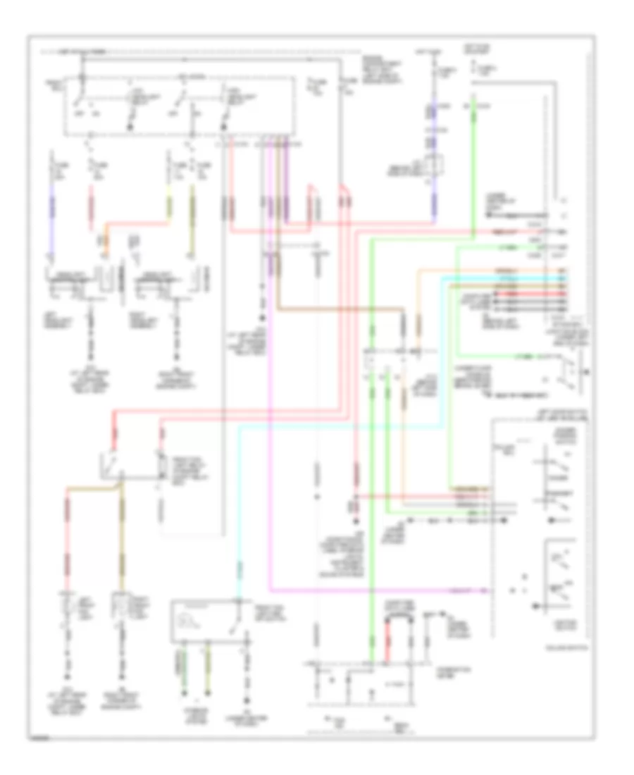
HEADLIGHTS Headlights Wiring Diagram, with High Intensity Discharge for Mitsubishi Eclipse Spyder GT 2012 List of elements for Headlights Wiring Diagram, with High Intensity Discharge for Mitsubishi Eclipse Spyder GT 2012: 56 (under center of dash) g3 (under floor console, near parking brake lever) g17 A-13x A-14x Air conditioning, computer data lines, interior lights, instrument cluster & sound systems Beam ind C-208 C-215 C-217 C-218 C-24 C203 Column ecu Column switch Combination meter Computer data lines system Dimmer Dimmer/ passing switch Engine compartment relay box (left side of engine compt) Etacs ecu Fog ind Front ecu Front fog light relay (in engine compt relay box) Front fog light/asc off switch Fuse 10a Fuse 15a Fuse 2 7.5a Fuse 20a Fuse 5 7.5a G12 (at left rear of engine compt, under relay box) G3 (under center of dash) G4 (behind left side of dash) G9 (right front corner of engine compt) Head Headlight control unit High headlight relay Hot at all times Hot in on Hot in on or start Ill Interior lights system J/c 1 (behind left side of dash) J/c 2 (behind left side of dash) Junction block (under left end of dash) Left door switch (at left ''b'' pillar) Left front fog light Left headlight assembly Lighting switch Low headlight relay Off Passing Red Right front fog light Right headlight assembly Solenoid Tail Headlights Wiring Diagram, without High Intensity Discharge for Mitsubishi Eclipse Spyder GT 2012 List of elements for Headlights Wiring Diagram, without High Intensity Discharge for Mitsubishi Eclipse Spyder GT 2012: 58 (under center of dash) g3 (under floor console, near parking brake lever) g17 A-13x A-14x Air conditioning, computer data lines, interior lights, instrument cluster & sound systems Beam ind C-203 C-208 C-215 C-217 C-218 C-24 C203 Column ecu Column switch Combination meter Computer data lines system Dimmer Dimmer/ passing switch Engine compartment relay box (left side of engine compt) Etacs ecu Fog ind Front ecu Front fog light relay (in engine compt relay box) Front fog light switch Fuse 10a Fuse 15a Fuse 16 10a Fuse 17 10a Fuse 18 10a Fuse 19 10a Fuse 2 7.5a Fuse 5 7.5a G12 (at left rear of engine compt, under relay box) G3 (under center of dash) G4 (behind left side of dash) G9 (right front corner of engine compt) Head High headlight relay Hot at all times Hot in on Hot in on or start Ill Interior lights system J/c 1 (behind left side of dash) J/c 2 (behind left side of dash) Junction block (under left end of dash) Left door switch (at left ''b'' pillar) Left front fog light Left headlight Lighting switch Off Passing Pulse width modulator Red Right front fog light Right headlight Tail
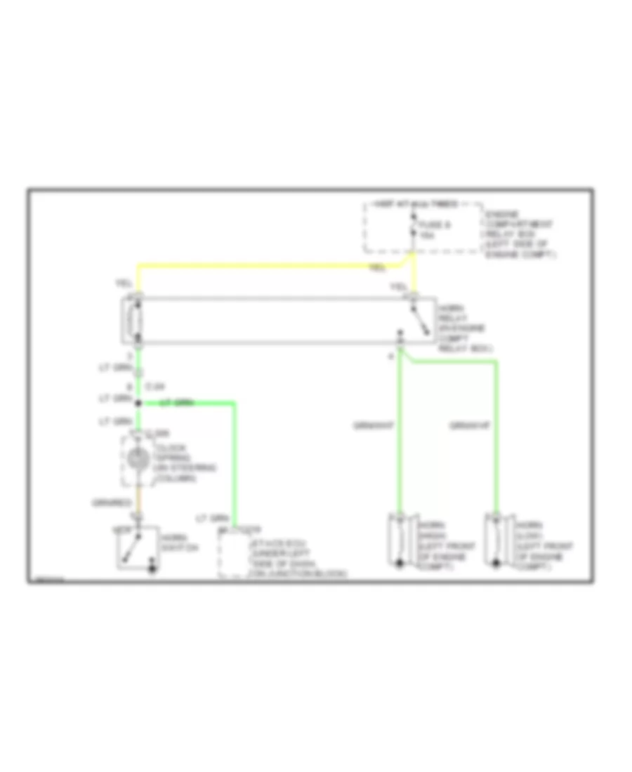
HORN Horn Wiring Diagram for Mitsubishi Eclipse Spyder GT 2012 List of elements for Horn Wiring Diagram for Mitsubishi Eclipse Spyder GT 2012: 13 C-24 C-306 C219 Clock spring (in steering column) Engine compartment relay box (left side of engine compt) Etacs ecu (under left side of dash, on junction block) Fuse 8 15a Horn (high) (left front of engine compt) Horn (low) (left front of engine compt) Horn relay (in engine compt relay box) Horn switch Hot at all times Nca
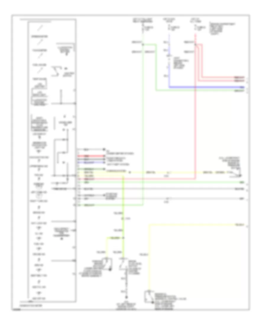
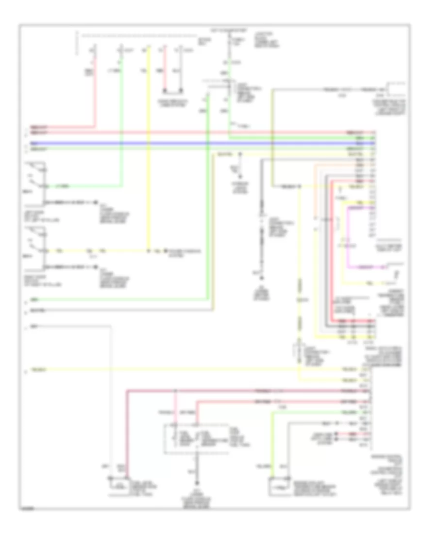
INSTRUMENT CLUSTER Instrument Cluster Wiring Diagram (1 of 2) for Mitsubishi Eclipse Spyder GT 2012 List of elements for Instrument Cluster Wiring Diagram (1 of 2) for Mitsubishi Eclipse Spyder GT 2012: 54 (2.4l: lower right side of engine) engine oil pressure switch Anti lock ind Anti-theft system Asc off ind Asc/tcl ind Brake fluid level switch (on side of master cylinder) Brake ind C-23 C-24 Combination meter Computer data lines system Cpu Cruise ind Door ind Engine compartment relay box (left side of engine compt) Engine oil pressure switch (engine oil control valve) (2.4l: lower right side of engine) (3.8l: lower left rear of engine) Field effect transistor for illumination Fog ind Fuel gauge Fuel ind Fuse 20 7.5a Fuse 22 10a Fuse 23 15a G12 (at left rear of engine compt, under relay box) G3 (under center of dash) Generator malfunction light ind Hot at all times Hot in acc or on Hot w/ taillight relay energized Illumination control button Illumination pointer/ dial face Immobilizer ind Joint connector 2 (behind left side of dash) Lcd back light Lcd display Lcd odo/trip Left turn ind Malfunction ind Odo/trip Oil ind Parking brake switch (under center floor console, at base of parking brake assembly) Red Right turn ind Seat belt ind Shift indicator & transmission fluid temperature indicator Speedometer Srs ind Starting/ charging system Switch Tachometer Temp gauge Tire air ind Upper beam ind Warning system Instrument Cluster Wiring Diagram (2 of 2) for Mitsubishi Eclipse Spyder GT 2012 List of elements for Instrument Cluster Wiring Diagram (2 of 2) for Mitsubishi Eclipse Spyder GT 2012: 42 Ambient temperature sensor (type 1) (near lower left side of radiator) B-18 B-19 B-20 B-21 C-11 C-118 C-119 C-21 C-215 C-217 C-218 C-23 C-24 C-26 Computer data lines system Convertible top control module (left front of luggage compt) D-45 Engine control module (m/t) powertrain control module (a/t) (left side of engine compt, forward of relay box) Engine coolant temperature sensor (on rear of engine, near coolant outlet) Etacs ecu Fuel level sensor (main) Fuel level sensor (sub) (top of fuel tank) Fuel pump module (top of fuel tank) Fuel tank temperature sensor Fuse 2 7.5a G17 (under floor console, near parking brake lever) G3 (under center of dash) Hot in on or start Interior lights system Joint connector 1 (behind left side of dash) Joint connector 2 (behind left side of dash) Junction block (under left end of dash) Left door switch (at left "b" pillar) Multi center display unit Power windows system Radio, cd player & cd changer (w/ audio amplifier) radio & cd player (w/o audio amplifier) Red Right door switch (at right "b" pillar) Type 1 W/ audio amplifier W/o audio amplifier
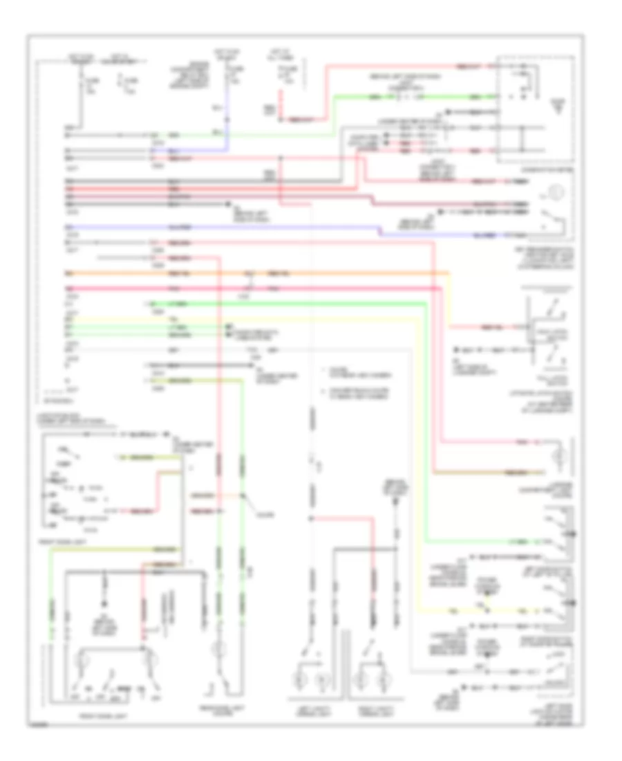
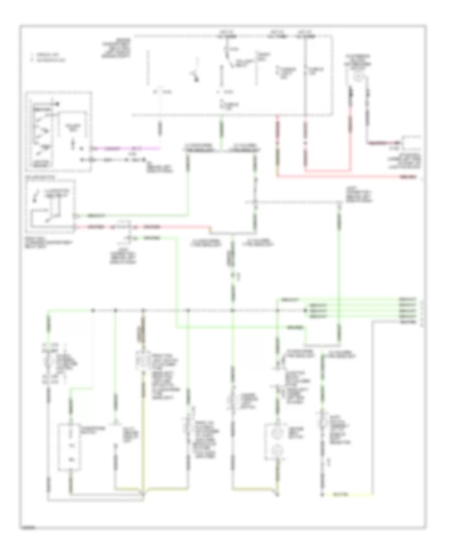
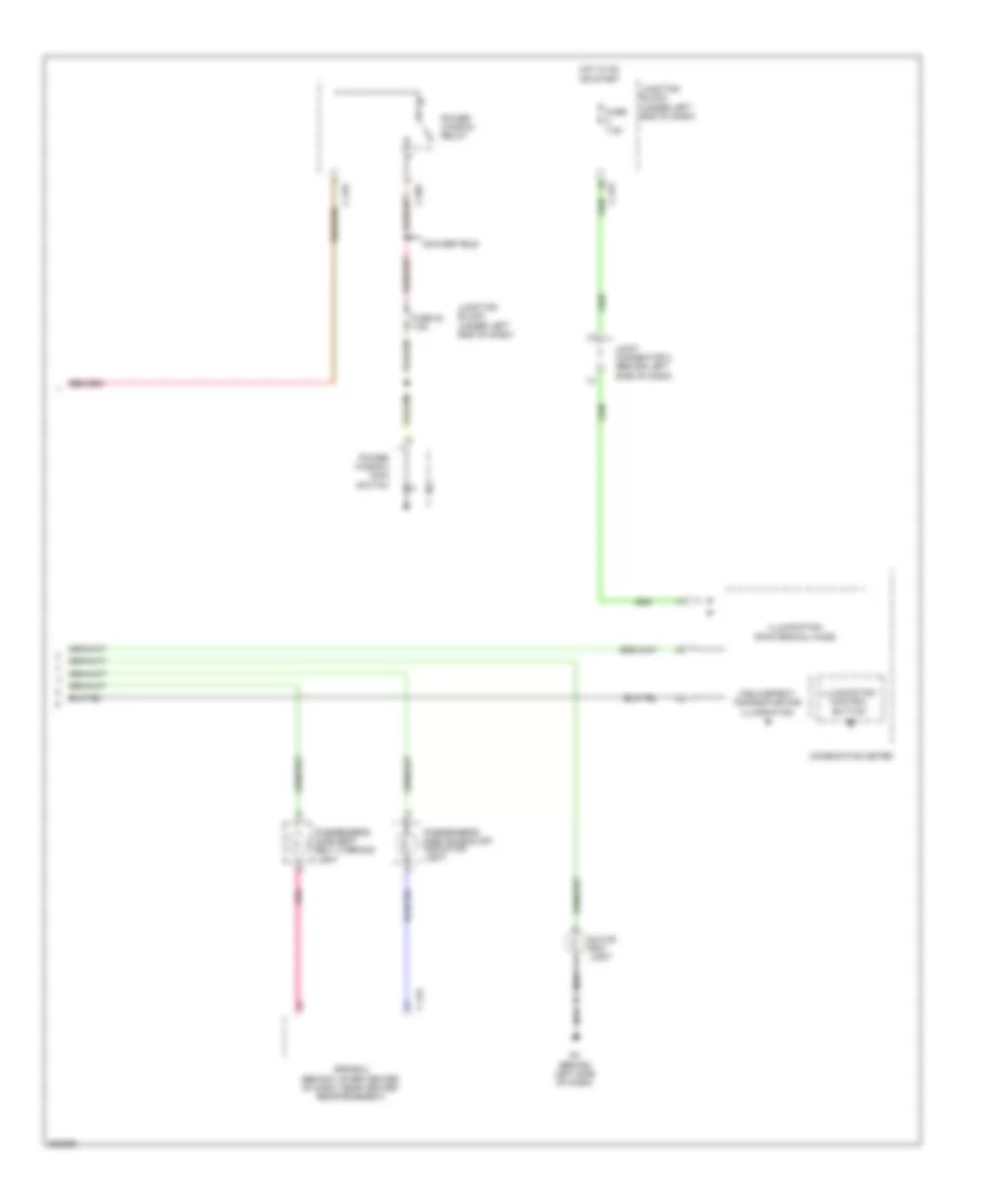
INTERIOR LIGHTS Courtesy Lamps Wiring Diagram for Mitsubishi Eclipse Spyder GT 2012 List of elements for Courtesy Lamps Wiring Diagram for Mitsubishi Eclipse Spyder GT 2012: 59 (behind left side of dash) g4 (behind left side of dash) joint connector 2 10a 15a C-23 C-25 C-27 C203 C208 C209 C215 C217 C218 C219 Combination meter Computer data lines system Convertible & coupe w/ rear view camera Coupe Coupe w/o rear view camera D-30 Door Door ind Engine compartment relay box (left side of engine compt) Etacs ecu Front dome light Full latch switch Fuse Fuse 15a Fuse 7.5a G17 (under floor console, near parking brake lever) G3 (under center of dash) G4 (behind left side of dash) G8 (left side of luggage compt) Half latch switch Hot at all times Hot in on or acc Hot in on or start Ill Joint connector 3 (behind left side of dash) Junction block (under left end of dash) Key reminder switch (ignition key hole illumination light) (in steering column) Left door lock actuator (inside rear of left door) Left door switch (at left "b" pillar) Left vanity mirror light Liftgate latch switch (coupe) (at center rear of luggage compt) Lock Luggage compartment light (coupe) Nca Off Off (door) Pnk Power windows system Rear dome light (coupe) Red Right door switch (at right "b" pillar) Right vanity mirror light Unlock W/ sunroof W/o sunroof Instrument Illumination Wiring Diagram (1 of 2) for Mitsubishi Eclipse Spyder GT 2012 List of elements for Instrument Illumination Wiring Diagram (1 of 2) for Mitsubishi Eclipse Spyder GT 2012: 44 (in steering column) key reminder switch A/c ecu (integral to heater control unit) A13x A14x Amplifier) Automatic a/c C-117 C-128 C-19 C-20 C-21 C-24 C203 C215 Column switch Column- ecu Dimmer Engine compartment relay box (left side of engine compt) Etacs ecu (under left side of dash, on junction block) Front ecu Front ecu (in engine compartment relay box) Front fog light switch (w/ halogen type headlight) front fog light/asc off switch (w/ discharge type headlight) Fuse 20 7.5a Fuse 22 10a Fusible link 5 30a G4 (behind left side of dash) Hazard warning light switch Head Heated seat switch Hot at all times Illumination light relay Joint connector 1 (behind left side of dash) Junction block (w/ halogen type headlight) (under left end of dash) Lighting switch Manual a/c Microphone switch Multi- center display unit Nca Radio, cd player & cd changer (w/ audio amplifier) radio & cd player (w/o audio c-117 Shift switch assembly (a/t: at base of shift selector) Tail Taillight relay W/ discharge type headlight W/ halogen type headlight Instrument Illumination Wiring Diagram (2 of 2) for Mitsubishi Eclipse Spyder GT 2012 List of elements for Instrument Illumination Wiring Diagram (2 of 2) for Mitsubishi Eclipse Spyder GT 2012: 24 7.5a C-123 C-202 C-215 C-216 Combination meter Convertible Field effect transistor for illumination Fuse Fuse 23 7.5a G4 (behind left side of dash) Glove box light Hot in on or start Ill Illumination (pointer/dial face) Illumination control button Joint connector 2 (behind left side of dash) Junction block (under left end of dash) Passenger's side air bag off indicator light Passenger's side seat belt warning light Pnk Power window main switch Power window relay Srs-ecu (behind lower center of dash, near center reinforcement)
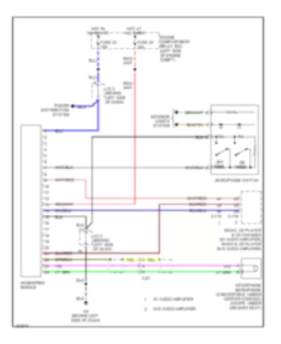
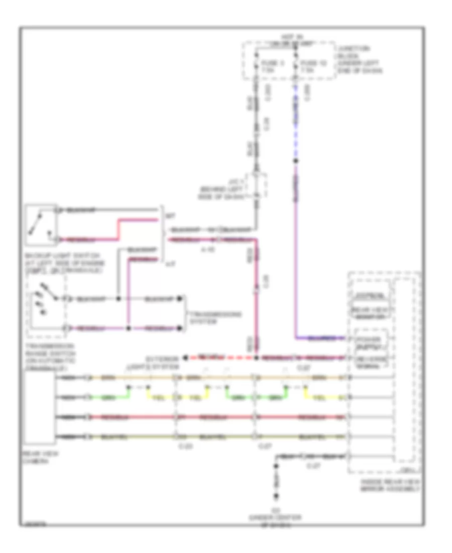
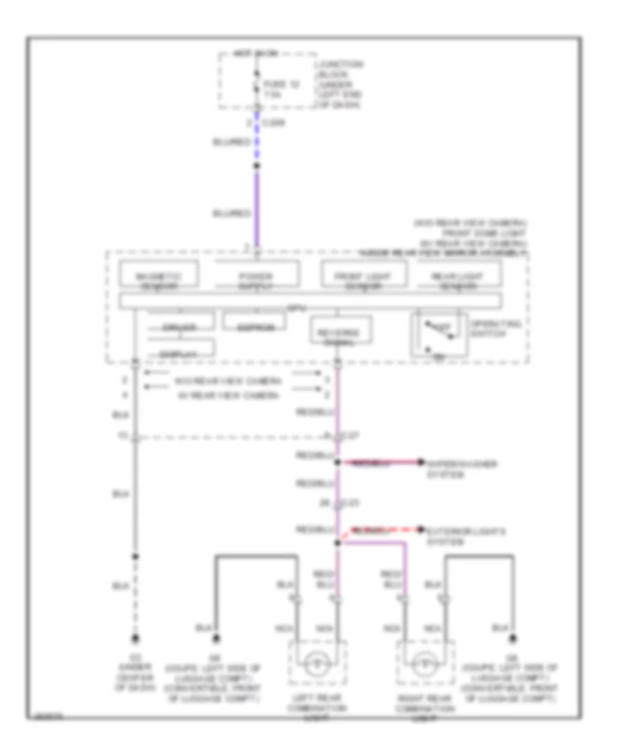
NAVIGATION Hands Free Module Wiring Diagram for Mitsubishi Eclipse Spyder GT 2012 List of elements for Hands Free Module Wiring Diagram for Mitsubishi Eclipse Spyder GT 2012: 21 C-118 C-119 C-27 Engine compartment relay box (left side of engine compt) Fuse 22 10a Fuse 23 15a G4 (behind left side of dash) Handsfree module Hot at all times Hot in on or acc Ill Interior lights system Interphone microphone (convertible: under center console) (coupe: under driver's seat) J/c 2 (behind left side of dash) Microphone switch Off hook On hook Power distribution system Radio, cd player & cd changer (w/ audio amplifier) radio & cd player (w/o audio amplifier) W/ audio amplifier W/o audio amplifier Rear View Camera Wiring Diagram for Mitsubishi Eclipse Spyder GT 2012 List of elements for Rear View Camera Wiring Diagram for Mitsubishi Eclipse Spyder GT 2012: 26 A-15 A/t Backup light switch (at left side of engine compt, on transaxle) C-203 C-209 C-23 C-24 C-26 C-27 Cpu Eeprom Exterior lights system Fuse 12 7.5a Fuse 3 7.5a G3 (under center of dash) Hot in on or start Inside rear view mirror assembly J/c 1 (behind left side of dash) Junction block (under left end of dash) M/t Nca Rear view camera Rear view monitor Reverse signal Transmission range switch (on automatic transaxle) Transmissions system
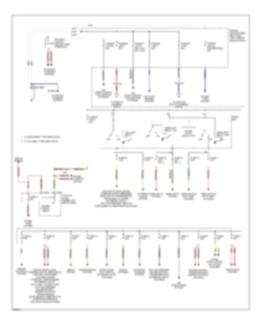
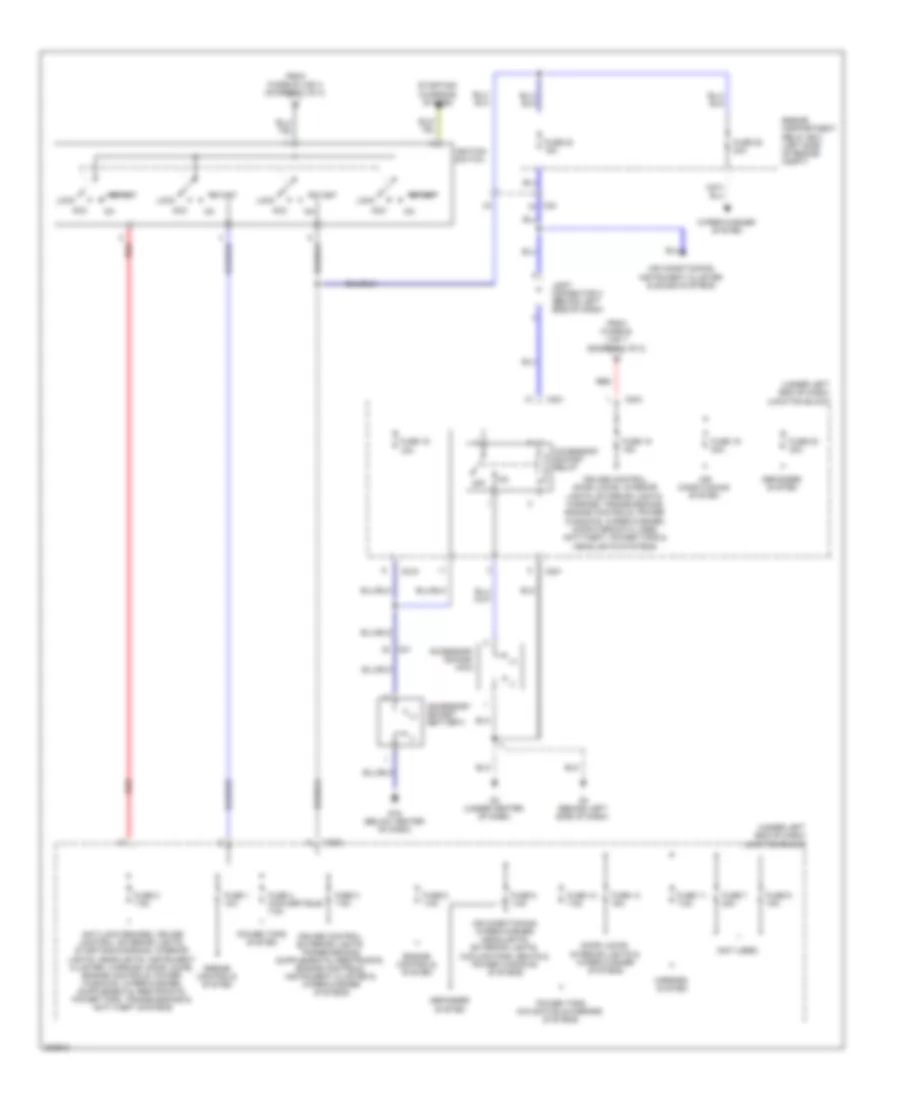
POWER DISTRIBUTION Power Distribution Wiring Diagram (1 of 2) for Mitsubishi Eclipse Spyder GT 2012 List of elements for Power Distribution Wiring Diagram (1 of 2) for Mitsubishi Eclipse Spyder GT 2012: 64 (2.4l) (3.8l) 120a Air conditioning & cooling fans systems Air conditioning system Anti-lock brakes system Anti-lock brakes, cruise control, transmissions & exterior lights systems Battery C202 C216 C24 Cruise control, transmissions & engine controls systems Door locks, anti-theft & exterior lights systems Engine compartment relay box (left side of engine compt) Engine controls system Exterior lights system Front ecu Fuse 10 10a Fuse 11 7.5a Fuse 12 30a Fuse 13 7.5a Fuse 14 10a Fuse 15 20a Fuse 16 10a Fuse 17 10a Fuse 18 20a 10a Fuse 19 20a 10a Fuse 20 7.5a Fuse 21 20a Fuse 21 7.5a Fuse 22 10a Fuse 24 15a Fuse 6 15a Fuse 7 20a Fuse 8 15a Fuse 9 20a Fusible link 1 80a Fusible link 2 30a 50a Fusible link 26 20a Fusible link 27 (on battery terminal) Fusible link 28 (convertible) 40a Fusible link 3 60a Fusible link 4 40a Fusible link 5 30a Headlight relay high Headlight relay low Headlights & anti-theft systems Headlights system Horns, door locks & anti-theft systems Junction block (under left end of dash) Off Power tops system Power window relay Power windows system Pulse width modulator Red Seats system Sound systems Starting/ charging system Taillight relay To fuse 15 (diagram 2 of 2) To ignition switch (diagram 2 of 2) Transmissions system W/ discharge type headlights W/ halogen type headlights Power Distribution Wiring Diagram (2 of 2) for Mitsubishi Eclipse Spyder GT 2012 List of elements for Power Distribution Wiring Diagram (2 of 2) for Mitsubishi Eclipse Spyder GT 2012: 55 (+) (-) (not used) (under left end of dash) junction block Acc Accessory socket (acc) Accessory socket (battery) Accessory socket relay Air conditioning system Air conditioning, instrument cluster & sound systems Air conditioning, wiper/washer, headlights, exterior lights, cooling fans, seats & power windows systems C201 C202 C204 C21 C215 C24 Cruise control, door locks, interior lights, exterior lights, warning, transmissions, engine controls, power windows, wiper/washer, computer data lines, anti-theft, power tops & headlights systems Defogger system Door locks, interior lights & wiper/washer systems Engine compartment relay box (left side of engine compt) Engine controls system From fusible link 1 (diagram 1 of 2) From fusible link 4 (diagram 1 of 2) Fuse 1 10a Fuse 11 7.5a Fuse 12 7.5a Fuse 14 15a Fuse 15 15a Fuse 16 15a Fuse 19 30a Fuse 2 7.5a Fuse 20 30a Fuse 23 15a Fuse 25 30a Fuse 3 7.5a Fuse 4 (convertible) 7.5a Fuse 5 7.5a Fuse 7 20a Fuse 8 7.5a Fuse 9 15a G16 (below center of dash) G3 (under center of dash) G4 (behind left side of dash) Ignition switch Joint connector 2 (behind left side of dash) Lock Mirrors system Off Power tops navigation & mirrors systems Power tops system Red Start Starting/ charging system Wiper/washer system
POWER DOOR LOCKS Power Door Locks Wiring Diagram for Mitsubishi Eclipse Spyder GT 2012 List of elements for Power Door Locks Wiring Diagram for Mitsubishi Eclipse Spyder GT 2012: 70 (behind left side of dash) g4 (behind left side of dash) joint connector 2 (in steering column) key reminder switch A-13x A-14x C-09 C-11 C-203 C-208 C-209 C-215 C-217 C-218 C-219 C-23 C-24 C-25 Combination meter Computer data lines system Convertible Convertible top control module (convertible) (left front of luggage compt) Coupe D-45 Door ind E-06 Engine compartment relay box (left side of engine compt) Etacs-ecu Exterior lights system F-02 Front ecu Fuse 10a Fuse 14 10a Fuse 14 15a Fuse 15 15a Fuse 15a Fuse 2 7.5a G12 (at left rear of engine compt, under relay box) G17 (under floor console, near parking brake lever) G3 (under center of dash) G4 (behind left side of dash) G6 (convertible: front of luggage compt) (coupe: left side of liftgate) G7 (left side of liftgate) G8 (convertible: front of luggage compt) (coupe: left side of luggage compt) Headlights system High headlamp relay Hood switch (right side of engine compt) Horns system Hot at all times Hot in acc or on Hot in on or acc Hot in on or start Interior lights system Junction block (under left end of dash) Left door lock actuator (inside rear of left door) Left door switch (at left "b" pillar) Liftgate lock actuator (at center rear of luggage compt) Liftgate lock release handle Lock Nca Power window main switch Power window sub switch Power windows system Red Right door lock actuator (inside rear of right door) Right door switch (at right "b" pillar) Security ind Security indicator Trunk lid latch switch (convertible) (center rear of luggage compt) Trunk lid opener switch (center rear of luggage compt lid) Unlock
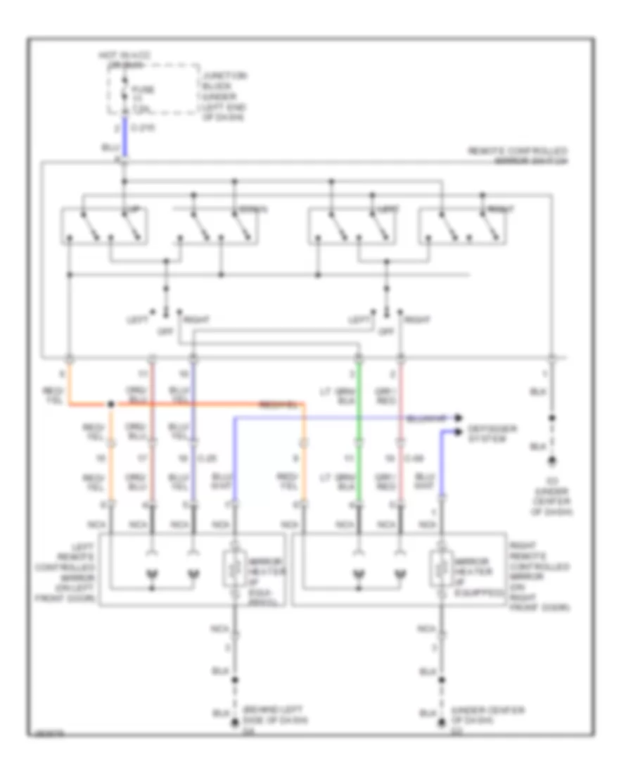
POWER MIRRORS Automatic Day/Night Mirror Wiring Diagram for Mitsubishi Eclipse Spyder GT 2012 List of elements for Automatic Day/Night Mirror Wiring Diagram for Mitsubishi Eclipse Spyder GT 2012: 26 (w/o rear view camera) front dome light (w/ rear view camera) inside rear view mirror assembly C-209 C-23 C-27 Cpu Display Driver Eeprom Exterior lights system Front light sensor Fuse 12 7.5a G3 (under center of dash) G8 (coupe: left side of luggage compt) (convertible: front of luggage compt) Hot in on Junction block (under left end of dash) Left rear combination light Magnetic sensor Nca Off Operating switch Rear light sensor Reverse signal Right rear combination light W/ rear view camera W/o rear view camera Wiper/washer system Power Mirror Wiring Diagram for Mitsubishi Eclipse Spyder GT 2012 List of elements for Power Mirror Wiring Diagram for Mitsubishi Eclipse Spyder GT 2012: 20 (behind left side of dash) g4 (under center of dash) g3 C-09 C-215 C-25 Defogger system Down Fuse 7.5a G3 (under center of dash) Hot in acc or run Junction block (under left end of dash) Left Left remote controlled mirror (on left front door) Mirror heater (if equi- pped) Mirror heater (if equipped) Nca Off Remote controlled mirror switch Right Right remote controlled mirror (on right front door)
POWER SEATS Heated Seats Wiring Diagram for Mitsubishi Eclipse Spyder GT 2012 List of elements for Heated Seats Wiring Diagram for Mitsubishi Eclipse Spyder GT 2012: 31 (behind left side of dash) g4 (front of luggage compt) (convertible) g6 (left side of luggage compt) (coupe) g8 (under floor console, near parking brake lever) g17 C-11 C-201 C-215 C-23 C-24 Engine compartment relay box (left side of engine compt) Fuse 5 7.5a Fuse 7 20a Heated seat relay Heated seat switch Heater Hot at all times Hot in on Illum Ind Interior lights system J/c 2 (behind left side of dash) Junction block (under left end of dash) Left Left heated seat assembly (under driver's seat) Nca Off Right Right heated seat assembly (under front passenger's seat) Seat back heater Seat cushion heater Thermo- stat Power Seat Wiring Diagram for Mitsubishi Eclipse Spyder GT 2012 List of elements for Power Seat Wiring Diagram for Mitsubishi Eclipse Spyder GT 2012: 17 C-23 Down Engine compartment relay box (left side of engine compt) Front height Front height motor Fusible link 5 30a Fwd G17 (under floor console, near parking brake lever) Hot at all times Nca Power seat assembly (under driver's seat) Power seat switch Rear height Rear height motor Rwd Slide Slide motor
POWER TOP/SUNROOF Convertible Top Wiring Diagram for Mitsubishi Eclipse Spyder GT 2012 List of elements for Convertible Top Wiring Diagram for Mitsubishi Eclipse Spyder GT 2012: 49 (in tonneau compt) solenoid valve (5-bow cylinder) (in tonneau compt) solenoid valve (5-bow locking cylinder) (in tonneau compt) solenoid valve (rotary drive) (in tonneau compt) solenoid valve (tonneau drive cylinder) (in tonneau compt) solenoid valve (tonneau latch cylinder) (left front of luggage compt) convertible top relay (right front of luggage compt) g18 (right side of tonneau compt) hydraulic unit pump motor 5-bow sensor (left down) (left rear of tonneau) 5-bow sensor (right down) (right rear of tonneau) 5-bow sensor (right upper) (right side of tonneau compt) C203 C218 C23 C27 C31 Computer data lines system Convertible top buzzer (behind center of dash) Convertible top control module (left front of luggage compt) Convertible top position switch Convertible top switch D45 D46 Down Engine compa- rtment relay box (left side of engine compt) Etacs- ecu F26 F27 Fuse 10a Fuse 7.5a Fusible link 28 40a G3 (under center of dash) G6 (front of luggage compt) Hall ic Header latch switch (left end of windshield header) Hot at all times Hot in on Instrument cluster system Junction block (under left end of dash) Latched Nca Power windows system Ready to latch Red Sound systems Tonneau latch open sensor (right side of tonneau storage compt) Tonneau latch switch Tonneau sensor (drive cylinder: up) (right side of tonneau compt) Trunk, tailgate, fuel doors system Sunroof Wiring Diagram for Mitsubishi Eclipse Spyder GT 2012 List of elements for Sunroof Wiring Diagram for Mitsubishi Eclipse Spyder GT 2012: 31 C203 C209 C215 C217 C218 C27 Close/ down Computer data lines system D29 Engine compartment relay box (left side of engine compt) Etacs ecu Fuse 12 7.5a Fuse 2 7.5a Fuse 21 20a Fuse 22 10a G3 (under center of dash) G4 (behind left side of dash) Hall ic 1 Hall ic 2 Hot at all times Hot in on Hot in on or start Joint connector 2 (behind left side of dash) Junction block (under left end of dash) Off Open Pulse sensor Sunroof ecu Sunroof motor Sunroof motor assembly (on front center of roof) Sunroof switch
POWER WINDOWS Power Windows Wiring Diagram (1 of 2) for Mitsubishi Eclipse Spyder GT 2012 List of elements for Power Windows Wiring Diagram (1 of 2) for Mitsubishi Eclipse Spyder GT 2012: 42 (at right "b" pillar) C-09 C-11 C-23 C-24 C202 C203 C208 C215 C216 C217 C218 Computer data lines system Convertible top control module (convertible) (left front of luggage compt) D-40 D45 D46 Door locks system Down E-06 E-08 Engine compartment relay box (left side of engine compt) Etacs-ecu Fuse 22 10a Fuse 7.5a Fusible link 5 30a G17 (under floor console, near parking brake lever) G3 (under center of dash) G4 (behind left side of dash) Headlights, exterior lights & wiper/washer systems Hot at all times Hot in on or start Junction block (under left end of dash) Left door switch (at left "b" pillar) Left quarter power window motor (behind left quarterpanel) Nca Off Pnk Power window relay Power window sub switch Right door switch Right quarter power window motor (behind right quarterpanel) Power Windows Wiring Diagram (2 of 2) for Mitsubishi Eclipse Spyder GT 2012 List of elements for Power Windows Wiring Diagram (2 of 2) for Mitsubishi Eclipse Spyder GT 2012: 32 Auto down C-09 C-25 C215 Convertible Cpu Door locks system Down Driver's side switch Fuse 15a Fuse 7.5a G3 (under center of dash) G4 (behind left side of dash) Gnd Hot in on Ill Junction block (under left end of dash) Left door lock actuator (inside rear of left door) Left power window motor (in left front door) Left short stroke switch Lock Lock switch Motor Off Passenger's side switch Pnk Power window main switch Relay Right door lock actuator (inside rear of right door) Right power window motor (inside right front door) Right short stroke switch Un lock
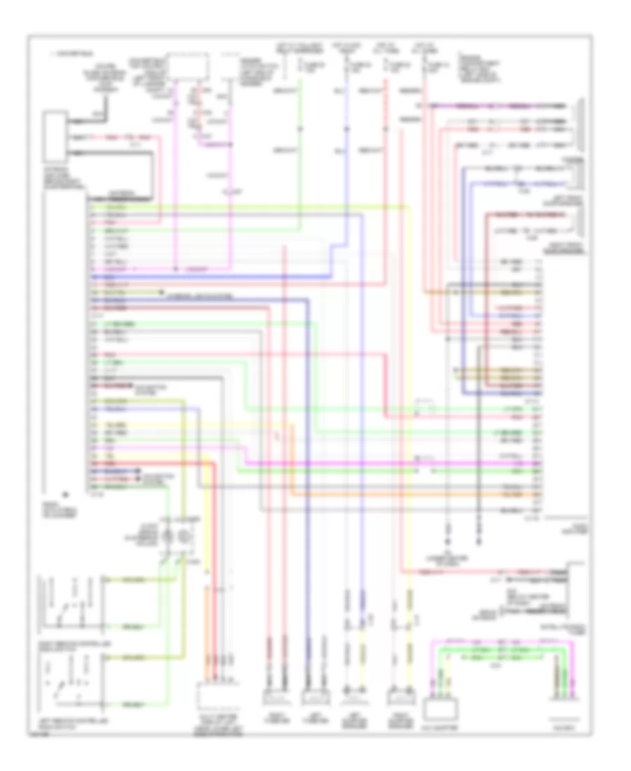
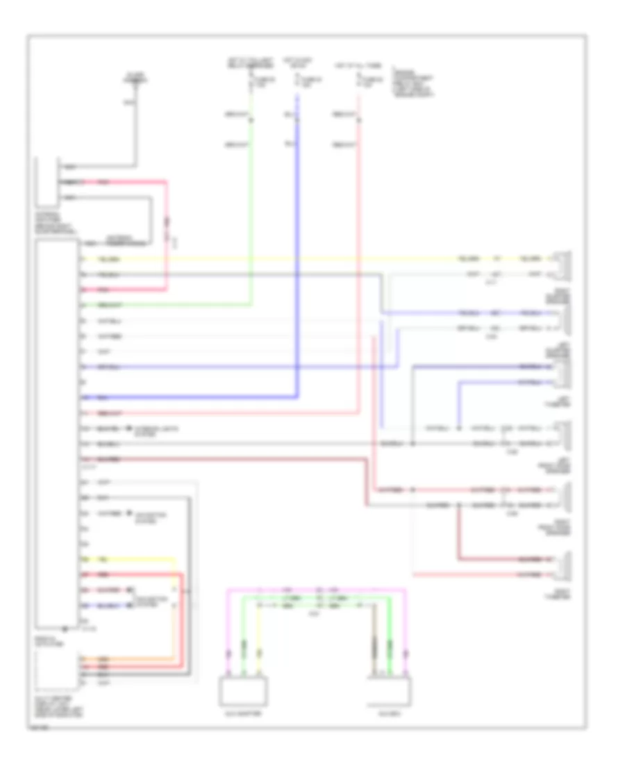
RADIO Radio Wiring Diagram, with Amplifier for Mitsubishi Eclipse Spyder GT 2012 List of elements for Radio Wiring Diagram, with Amplifier for Mitsubishi Eclipse Spyder GT 2012: 53 (antenna feeder cable) (coupe) glass antenna (convertible) whip antenna Antenna amplifier (behind right quarterpanel) Audio amplifier Aux adapter Aux box C-09 C-11 C-114 C-115 C-21 C-23 C-24 C-25 C-27 C-303 C-306 C117 C119 C27 Clock spring (in steering column) Convertible Convertible top control module (left front of luggage compt) D45 Engine compartment relay box (left side of engine compt) Fuse 12 30a Fuse 20 7.5a Fuse 22 10a Fuse 23 15a G16 (below center of dash) G3 (under center of dash) Header latch switch (left end of windshield header) Hot at all times Hot in acc or on Hot w/ taillight relay energized Interior lights system Left front door speaker Left quarter speaker Left remote controlled radio switch Left tweeter Multi center display unit (near lower left side of radiator) Navigation system Nca Pnk Radio, cd player & cd changer Red Right front door speaker Right quarter speaker Right remote controlled radio switch Right tweeter Satellite radio tuner Sirius antenna Woofer Radio Wiring Diagram, without Amplifier for Mitsubishi Eclipse Spyder GT 2012 List of elements for Radio Wiring Diagram, without Amplifier for Mitsubishi Eclipse Spyder GT 2012: 32 (antenna feeder cable) Antenna amplifier (behind right quarterpanel) Aux adapter Aux box C-09 C-11 C-117 C-118 C-21 C-23 C-25 Engine compartment relay box (left side of engine compt) Fuse 20 7.5a Fuse 22 10a Fuse 23 15a Glass antenna Hot at all times Hot in acc or on Hot w/ taillight relay energized Interior lights system Left front door speaker Left quarter speaker Left tweeter Multi center display unit (near lower left side of radiator) Navigation system Nca Pnk Radio & cd player Red Right front door speaker Right quarter speaker Right tweeter
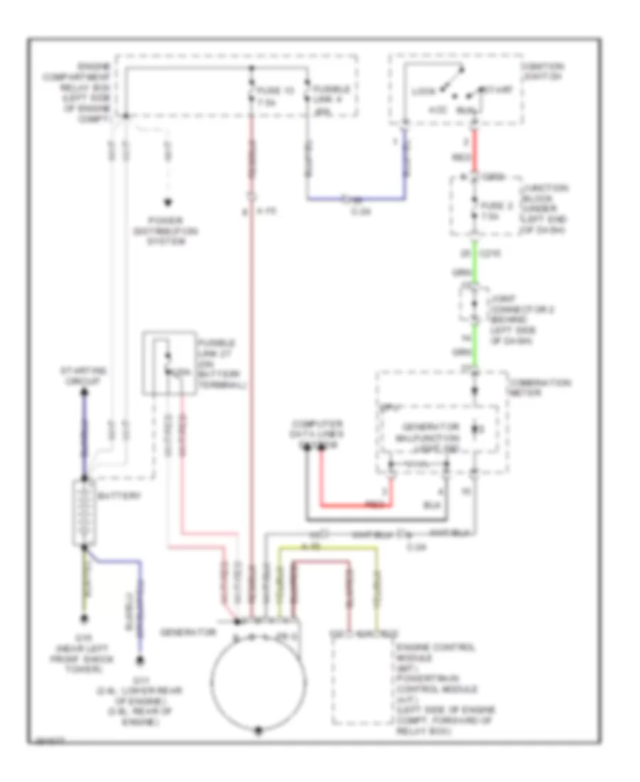
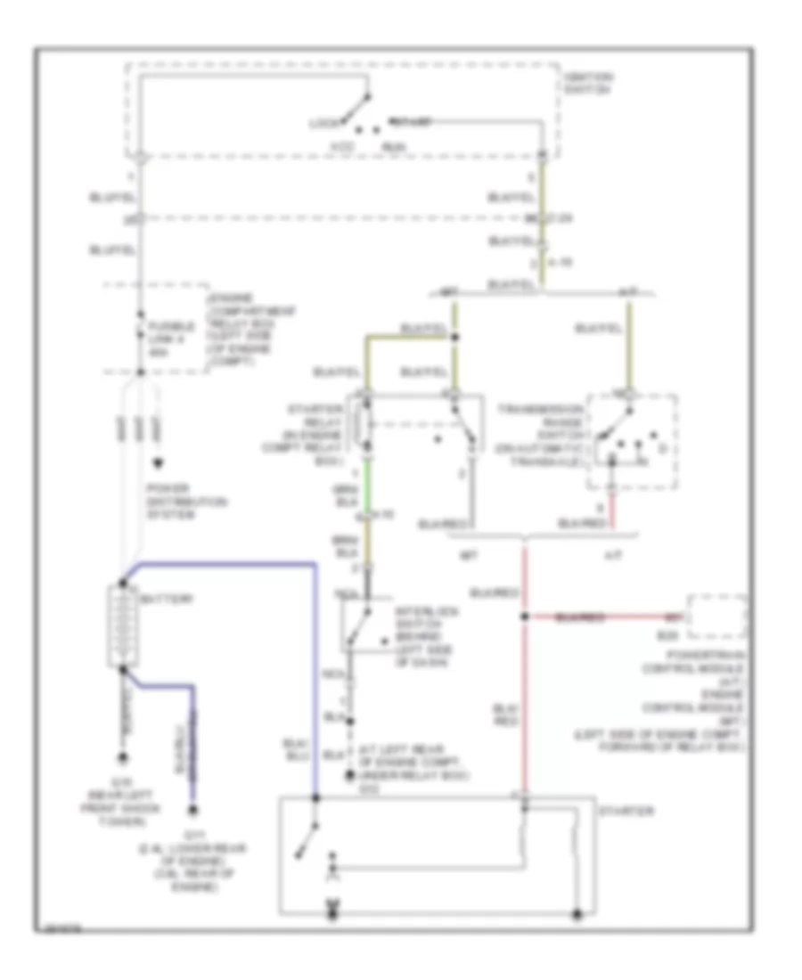
STARTING/CHARGING Charging Wiring Diagram for Mitsubishi Eclipse Spyder GT 2012 List of elements for Charging Wiring Diagram for Mitsubishi Eclipse Spyder GT 2012: 32 120a 40a 7.5a A-15 Acc B22 Battery C-24 C202 C215 Combination meter Computer data lines system Cpu Engine compartment relay box (left side of engine compt) Engine control module (m/t) powertrain control module (a/t) (left side of engine compt, forward of relay box) Fuse 13 Fuse 2 7.5a Fusible link 27 (on battery terminal) Fusible link 4 G11 (2.4l: lower rear of engine) (3.8l: rear of engine) G15 (near left front shock tower) Generator Generator malfunction light ind Ignition switch Joint connector 2 (behind left side of dash) Junction block (under left end of dash) Lock Power distribution system Red Run Start Starting circuit Starting Wiring Diagram for Mitsubishi Eclipse Spyder GT 2012 List of elements for Starting Wiring Diagram for Mitsubishi Eclipse Spyder GT 2012: 24 (at left rear of engine compt, under relay box) g12 A-15 A/t A15 Acc B20 Battery C-24 Engine compartment relay box (left side of engine compt) Fusible link 4 40a G11 (2.4l: lower rear of engine) (3.8l: rear of engine) G15 (near left front shock tower) Ignition switch Interlock switch (behind left side of dash) Lock M/t Nca Power distribution system Powertrain control module (a/t) engine control module (m/t) (left side of engine compt, forward of relay box) Run Start Starter Starter relay (in engine compt relay box) Transmission range switch (on automatic transaxle)
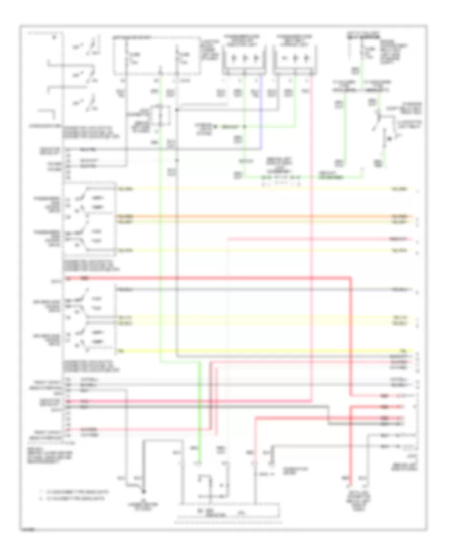
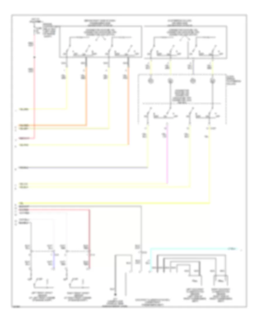
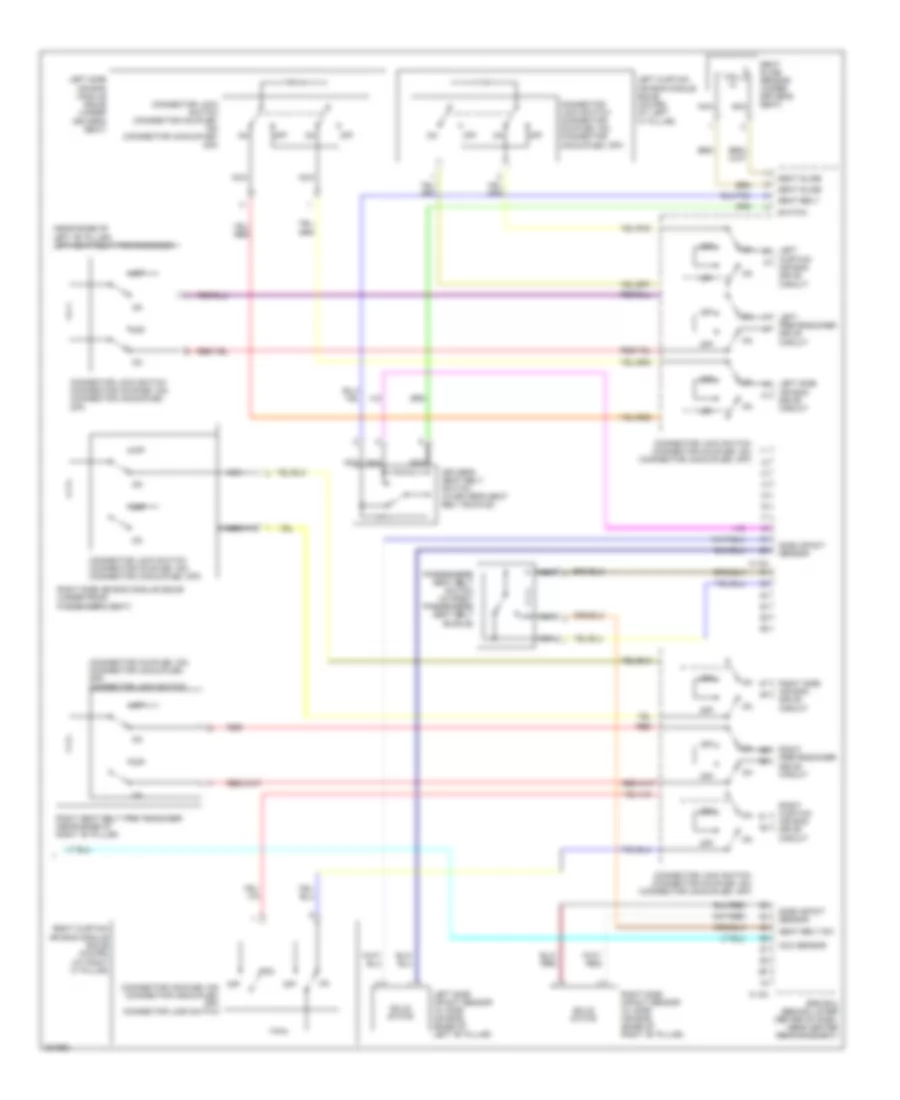
SUPPLEMENTAL RESTRAINTS Supplemental Restraints Wiring Diagram (1 of 3) for Mitsubishi Eclipse Spyder GT 2012 List of elements for Supplemental Restraints Wiring Diagram (1 of 3) for Mitsubishi Eclipse Spyder GT 2012: 37 (behind left side of dash) joint connector 1 (in engine compt relay box) front ecu C-123 C-215 C-24 Combination meter Connector lock switch (connector coupled: on) (connector uncoupled: off) Cpu Data Data link connector (below left side of dash) Driver's side air bag drive Engine compartment relay box (left side of engine compt) Front impact Fuse 7.5a G3 (under center of dash) Gnd Hot in on or start Hot w/ taillight relay energized Illumination light relay Indicator drive ckt Interior lights system Joint (behind left side of dash) Joint connector (behind left side of dash) Junction block (under left end of dash) Microcomputer Off Passenger's side air bag drive Passenger's side air bag off indicator light Passenger's side seat belt warning light Pnk Power Red Sens interface Srs ecu (behind lower center of dash, near center reinforcement) Srs indicator W/ discharge type headlights W/ halogen type headlights Supplemental Restraints Wiring Diagram (2 of 3) for Mitsubishi Eclipse Spyder GT 2012 List of elements for Supplemental Restraints Wiring Diagram (2 of 3) for Mitsubishi Eclipse Spyder GT 2012: 20 (behind right side of dash) passenger's side air bag module squib (connector coupled: on) (connector uncoupled: off) connector lock switch (connector coupled: on) connector uncoupled: off) connector lock switch (in steering column) driver's side air bag module squib C-10 C-21 C-23 C-307 Clock spring (in steering column) Engine compartment relay box (left side of engine compt) Fuse 10a G17 (under floor console, near parking brake lever) Hot at all times Left front impact sensor (at left front corner of engine compt) Left occupant classification sensor (left side of front passenger's seat) Nca Occupant classification ecu (under front passenger's seat) Off Right front impact sensor (at right front corner of engine compt) Right occupant classification sensor (right side of front passenger's seat) Supplemental Restraints Wiring Diagram (3 of 3) for Mitsubishi Eclipse Spyder GT 2012 List of elements for Supplemental Restraints Wiring Diagram (3 of 3) for Mitsubishi Eclipse Spyder GT 2012: 34 (connector coupled: on) (connector uncoupled: off) connector lock switch (near base of left "b" pillar) left seat belt pretensioner C-122 C-124 Connector lock switch (connector coupled: on) (connector uncoupled: off) Driver's seat belt switch (in driver's seat belt buckle) Hall ic Left curtain air bag drive circuit Left curtain air bag module squib (coupe) (at left "c" pillar) Left pretensioner drive circuit Left side air bag drive circuit Left side air bag module squib (under driver's seat) Left side impact sensor (w/ side air bag) (base of left "b" pillar) Nca Occ sensor Off Off (connector coupled: on) (connector uncoupled: off) connector lock switch Passenger's seat belt switch (in front passenger's seat belt buckle) Red Right curtain air bag drive circuit Right curtain air bag module squib (coupe) (at right "c" pillar) Right pretensioner drive circuit Right seat belt pre-tensioner (near base of right "b" pillar) Right side air bag drive circuit Right side air bag module squib (under front passenger's seat) Right side impact sensor (w/ side air bag) (base of right "b" pillar) Seat belt Seat belt sw Seat slide Seat slide sensor (under driver's seat) Side impact sensor Solid state Srs ecu (behind lower center of dash, near center reinforcement) Switch
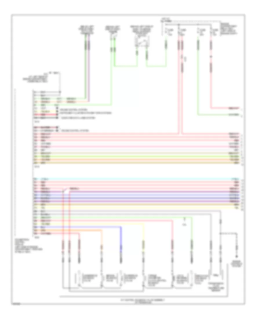
TRANSMISSION Transmission Wiring Diagram (1 of 3) for Mitsubishi Eclipse Spyder GT 2012 List of elements for Transmission Wiring Diagram (1 of 3) for Mitsubishi Eclipse Spyder GT 2012: 32 (behind left side of dash) j/c c-28 (behind left side of dash, on brake pedal support) stoplight switch (below left 3.8l A-15 A/t control solenoid valve assembly (in transaxle) B-18 B-19 B-20 C-21 Computer data lines system Cruise control system Data link connector Engine compartment relay box (left side of engine compt) Engine controls system Fuse 10a Fuse 20a Fuse 7.5a G12 (at left rear of engine compartment, under relay box) Hot at all times Instrument cluster & power tops systems Low & reverse solenoid valve Nca Overdrive solenoid valve Powertrain control module (left side of engine compartment, forward of relay box) Red Reduction solenoid valve (3.8l) Second solenoid valve Side of dash) Torque converter clutch control solenoid valve Transmission fluid temperature sensor Underdrive solenoid valve Transmission Wiring Diagram (2 of 3) for Mitsubishi Eclipse Spyder GT 2012 List of elements for Transmission Wiring Diagram (2 of 3) for Mitsubishi Eclipse Spyder GT 2012: 24 (in engine compt relay box) mfi relay (main) (sub) A-15 Accelerator pedal position sensor (top of accelerator pedal assembly) C-203 C-215 C-24 Combination meter Computer data lines system Cpu Engine controls system Field effect transistor illumination Fuse 7.5a G3 (under center of dash) Hall ic Hot in on or start Interior lights system J/c c-01 (behind left side of dash) J/c c-28 (behind left side of dash) Junction block (under left end of dash) Lcd back light Lcd display (shift indicator) (transmission fluid temperature indicator) Red Transmission Wiring Diagram (3 of 3) for Mitsubishi Eclipse Spyder GT 2012 List of elements for Transmission Wiring Diagram (3 of 3) for Mitsubishi Eclipse Spyder GT 2012: 25 (at base of shift selector) shift switch assembly (in engine compt relay box) a/t control relay (left side of engine compartment, on transaxle) input shaft speed sensor (left side of engine compartment, on transaxle) output shaft speed sensor (on automatic transaxle) transmission range switch 2.4l 3.8l A-15 Auto mode B-125 B-21 Crankshaft position sensor (near crankshaft sprocket) Crankshaft position sensor (on front of engine, near crankshaft) Engine controls system Exterior lights system Ill Interior lights system Nca Off Powertrain control module (left side of engine compartment, forward of relay box) Red Select switch Shift switch (down) Shift switch (up) Sport mode
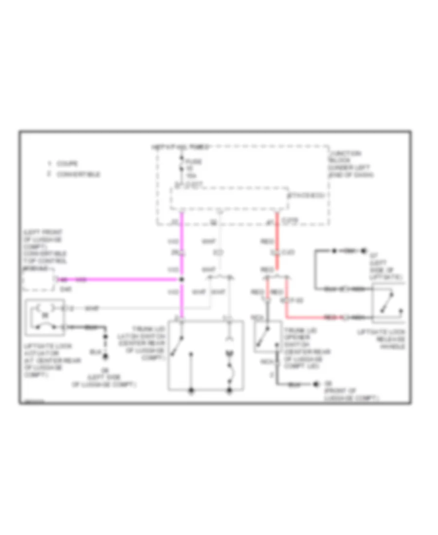
TRUNK, TAILGATE, FUEL DOOR Trunk Release Wiring Diagram for Mitsubishi Eclipse Spyder GT 2012 List of elements for Trunk Release Wiring Diagram for Mitsubishi Eclipse Spyder GT 2012: 21 (left front of luggage compt) convertible top control module C-217 C-219 C-23 Convertible Coupe D45 Etacs-ecu F-02 Fuse 15a G6 (front of luggage compt) G7 (left side of liftgate) G8 (left side of luggage compt) Hot at all times Junction block (under left end of dash) Liftgate lock actuator (at center rear of luggage compt) Liftgate lock release handle Nca Red Trunk lid latch switch (center rear of luggage compt) Trunk lid opener switch (center rear of luggage compt lid)
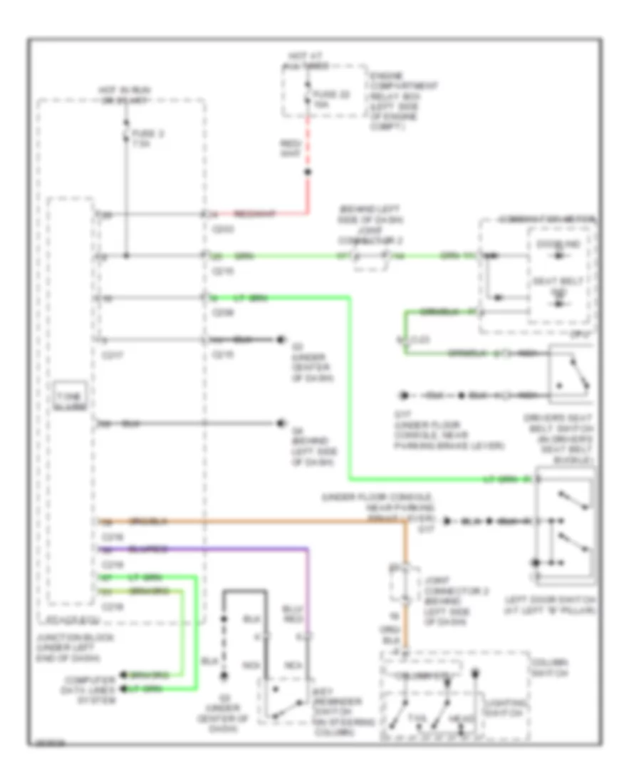
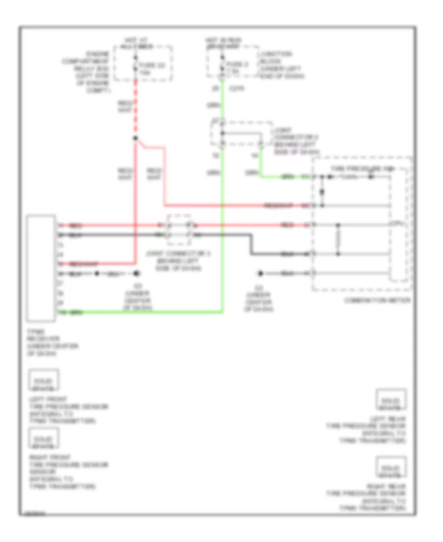
WARNING SYSTEMS Chime Wiring Diagram for Mitsubishi Eclipse Spyder GT 2012 List of elements for Chime Wiring Diagram for Mitsubishi Eclipse Spyder GT 2012: 35 (behind left side of dash) joint connector 2 (under floor console, near parking brake lever) g17 C-23 C203 C208 C215 C217 C218 C219 Column ecu Column switch Combination meter Computer data lines system Cpu Door ind Driver's seat belt switch (in driver's seat belt buckle) Engine compartment relay box (left side of engine compt) Etacs ecu Fuse 2 7.5a Fuse 22 10a G17 (under floor console, near parking brake lever) G3 (under center of dash) G4 (behind left side of dash) Head Hot at all times Hot in run or start Joint connector 2 (behind left side of dash) Junction block (under left end of dash) Key reminder switch (in steering column) Left door switch (at left "b" pillar) Lighting switch Nca Seat belt ind Tail Tone alarm Tire Pressure Monitoring Wiring Diagram for Mitsubishi Eclipse Spyder GT 2012 List of elements for Tire Pressure Monitoring Wiring Diagram for Mitsubishi Eclipse Spyder GT 2012: 20 C215 Combination meter Cpu Engine compartment relay box (left side of engine compt) Fuse 2 7.5a Fuse 22 10a G3 (under center of dash) Hot at all times Hot in run or start Joint connector 2 (behind left side of dash) Joint connector 3 (behind left side of dash) Junction block (under left end of dash) Left front tire pressure sensor (integral to tpms transmitter) Left rear tire pressure sensor (integral to tpms transmitter) Red Right front tire pressure sensor sensor (integral to tpms transmitter) Right rear tire pressure sensor (integral to tpms transmitter) Solid state Tire pressure ind Tpms receiver (under center of dash)
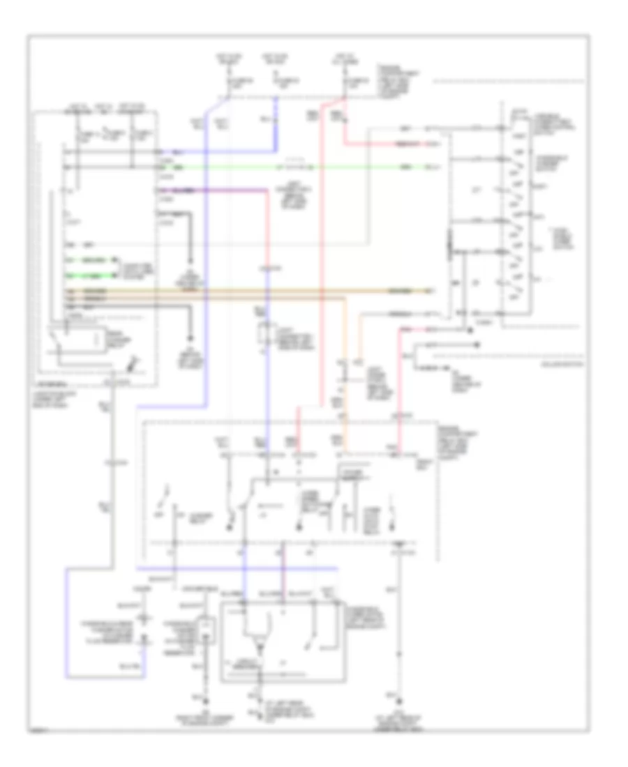
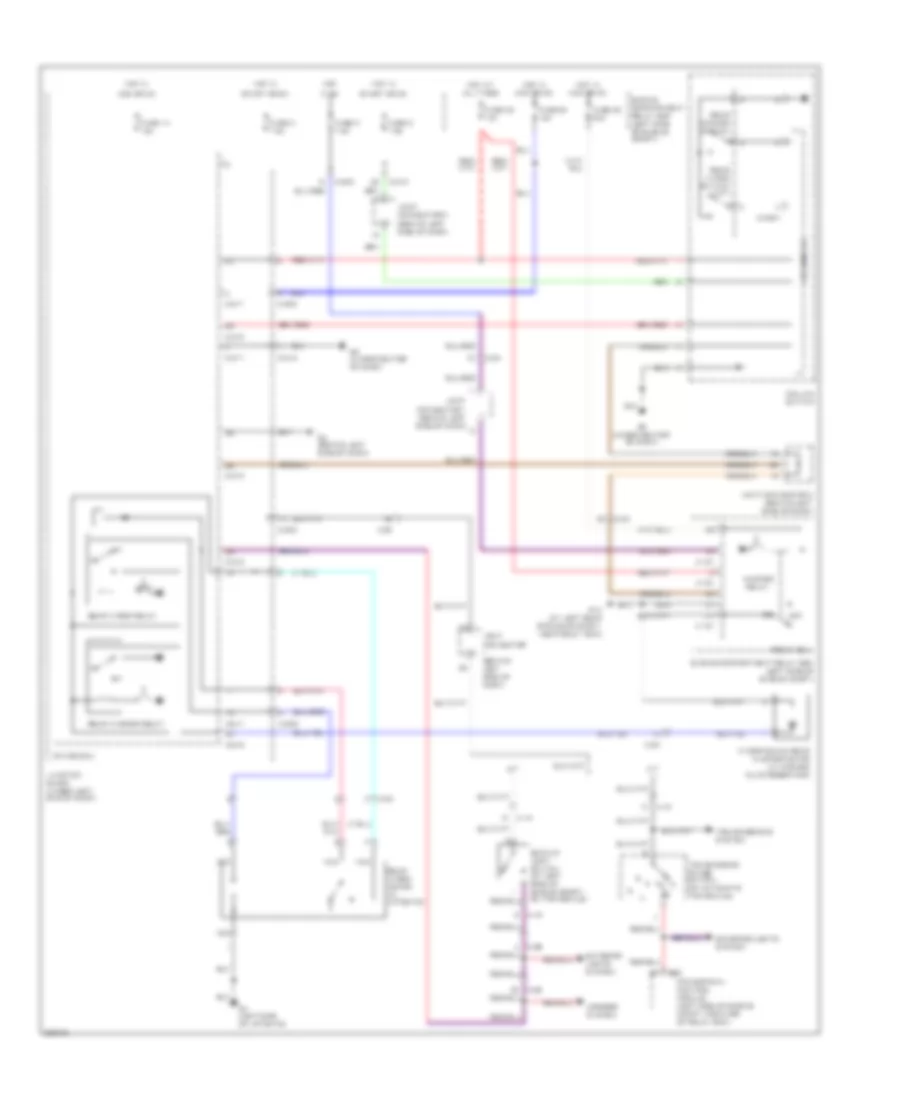
WIPER/WASHER Front Wiper/Washer Wiring Diagram for Mitsubishi Eclipse Spyder GT 2012 List of elements for Front Wiper/Washer Wiring Diagram for Mitsubishi Eclipse Spyder GT 2012: 56 (at left rear of engine compt, under relay box) g12 (hi) (int) (lo) (mist) A-13x A-14x C-203 C-215 C-217 C-218 C-219 C-24 C-309-1 Circuit breaker Column ecu Column switch Computer data lines system Convertible Coupe Engine compartment relay box (left side of engine compt) Etacs ecu Fast Front ecu Fuse 14 15a Fuse 2 7.5a Fuse 22 10a Fuse 23 15a Fuse 25 30a Fuse 5 7.5a G12 (at left rear of engine compt, under relay box) G3 (under center of dash) G4 (behind left side of dash) G9 (right front corner of engine compt) Gnd Hot at all times Hot in on Hot in on or acc Joint conne- ctor 2 (behind left side of dash) Joint connector 1 (behind left side of dash) Joint connector 2 (behind left side of dash) Junction block (under left end of dash) Off Or start Pnk Rear washer relay Slow Variable intermittent wiper control switch Washer relay Wind- shield wiper switch Windshield & rear washer motor (in washer fluid reservoir) Windshield washer motor (in washer fluid reservoir) Windshield washer switch Windshield wiper motor (left rear of engine compt) Wiper auto- matic stop relay Wiper speed switching relay Rear Wiper/Washer Wiring Diagram for Mitsubishi Eclipse Spyder GT 2012 List of elements for Rear Wiper/Washer Wiring Diagram for Mitsubishi Eclipse Spyder GT 2012: 59 A-15 A/t A13x A14x Acc or on B20 Backup light switch (at left side of engine compt, on transaxle) C-203 C-208 C-215 C-217 C-218 C-219 C-23 C-24 C-26 C-309-1 Column ecu Column switch Engine compartment relay box (left side of engine compt) Etacs ecu Exterior lights system F-02 Front ecu Fuse 14 15a Fuse 2 7.5a Fuse 22 10a Fuse 23 15a Fuse 25 30a Fuse 3 7.5a Fuse 5 7.5a G14 (at left rear of engine compt, near relay box) G3 (under center of dash) G4 (behind left side of dash) G7 (left side of liftgate) Hot Hot at all times Hot in Hot in acc or on In on Joint connector (behind left side of dash) Joint connector 1 (behind left side of dash) Joint connector 2 (behind left side of dash) Junction block (under left end of dash) M/t Mirrors system Nca Off Powertrain control module (left side of engine compt, forward of relay box) Rear washer relay Rear washer switch Rear wiper motor (in liftgate) Rear wiper relay Rear wiper switch (int) Start or on Transmission range switch (on automatic transaxle) Transmissions system Washer relay Windshield & rear washer motor (in washer fluid reservoir)