Diagram sections — 26 (69 total)
AIR CONDITIONING ANTI-LOCK BRAKES ANTI-THEFT BODY CONTROL MODULES COMPUTER DATA LINES COOLING FAN CRUISE CONTROL DEFOGGERS ENGINE PERFORMANCE EXTERIOR LIGHTS GROUND DISTRIBUTION HEADLIGHTS HORN INSTRUMENT CLUSTER INTERIOR LIGHTS POWER DISTRIBUTION POWER DOOR LOCKS POWER MIRRORS POWER TOP/SUNROOF POWER WINDOWS RADIO STARTING/CHARGING SUPPLEMENTAL RESTRAINTS TRANSMISSION WARNING SYSTEMS WIPER/WASHER
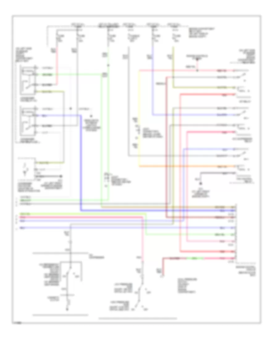
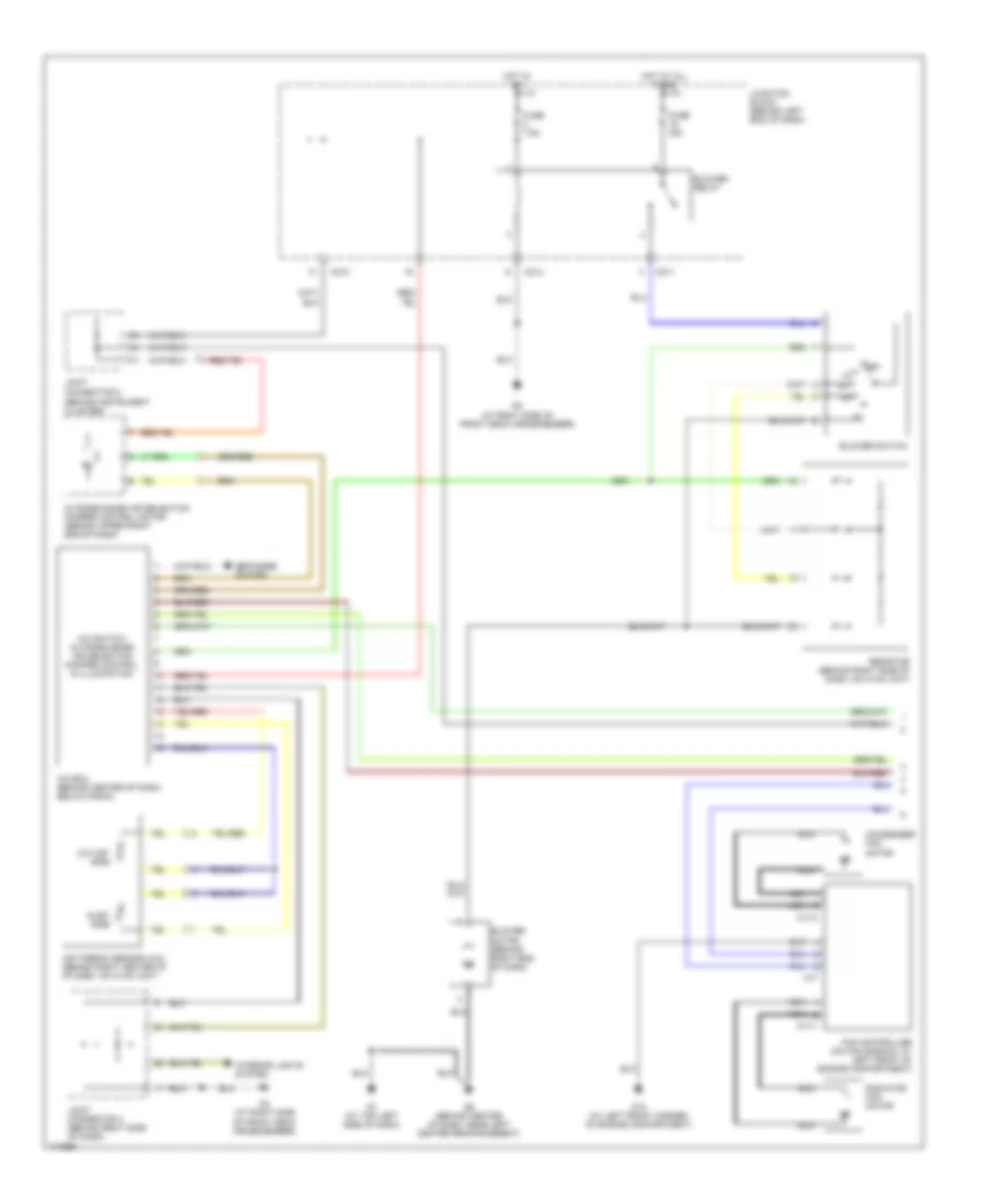
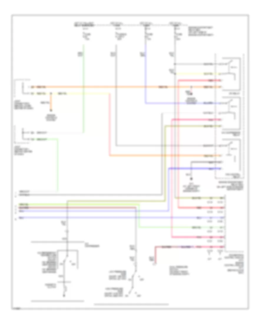
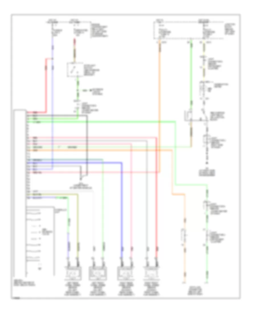
AIR CONDITIONING Manual A/C Wiring Diagram, Evolution (1 of 2) for Mitsubishi Lancer ES 2003 List of elements for Manual A/C Wiring Diagram, Evolution (1 of 2) for Mitsubishi Lancer ES 2003: 34 (behind instrument cluster) A/c ecu (behind center of dash, below radio) A/c switch, outside/inside air selection damper control & illumination A17 A17-1 Air thermo sensor (behind right center of of dash, on hvac unit) Blower motor (behind right end of dash) Blower relay Blower switch C210 C211 C214 Defogger system Fan control module (on fan shroud, at left front of engine compt) Fuse 30a Fuse 7.5a G13 (at left front corner of engine compartment) G3 (at right side of front deck crossmember) G6 (behind center of dash, near left center reinforcement) G7 (at top left side of dash) Hot at all times Hot in on Inlet side Interior lights system Joint connector 2 Joint connector 3 (behind right side of dash) Junction block (behind left end of dash) Nca Off Outlet side Outside/inside air selection damper control motor (behind upper right end of dash) Pnk Radiator fan motor Resistor (behind right side of dash, on hvac unit) Manual A/C Wiring Diagram, Evolution (2 of 2) for Mitsubishi Lancer ES 2003 List of elements for Manual A/C Wiring Diagram, Evolution (2 of 2) for Mitsubishi Lancer ES 2003: 38 (behind glove box) (on left side of engine compt) engine compartment relay box A/c compressor A/c compressor relay A/c refrigerant temperature switch (on-off: 150 degrees centigrade) (off-on: 120 degrees centigrade) A34 A35 C115 C119 C121 Condenser fan motor (mounted on rear of radiator) Condenser fan relay (hi) Condenser fan relay (lo) Dual pressure switch (on right side of engine compartment) Engine compartment relay box (on left side of engine compt) Engine control module Engine controls system Fan control relay Fuse 10a Fuse 20a Fuse 30a Fuse 7.5a Fusible link 2 50a G13 (at left front corner of engine compartment) G13 (at left front corner of engine compt) Headlights, exterior lights & wiper/washer systems High pressure side on-off: 3138 kpa off-on: 2550 kpa Hot at all times Hot w/ taillight relay energized Joint connector 1 (behind center of dash) Joint connector 6 (behind lower center of dash) Low pressure side on-off: 196 kpa off-on: 221 kpa Magnetic clutch Mfi relay Nca Off Pnk Red Manual A/C Wiring Diagram, Except Evolution (1 of 2) for Mitsubishi Lancer ES 2003 List of elements for Manual A/C Wiring Diagram, Except Evolution (1 of 2) for Mitsubishi Lancer ES 2003: 35 (behind instrument cluster) A/c ecu (behind center of dash, below radio) A/c switch, outside/inside air selection damper control & illumination A17 A17-1 A17-2 Air thermo sensor (a/c) (behind right center of of dash, on hvac unit) Blower motor (behind right end of dash) Blower relay Blower switch C210 C211 C214 Condenser fan motor Defogger system Fan controller (on fan shroud, at left front of engine compartment) Fuse 30a Fuse 7.5a G13 (at left front corner of engine compartment) G3 (at right side of front deck crossmember) G6 (behind center of dash, near left center reinforcement) G7 (at top left side of dash) Hot at all times Hot in on Inlet side Interior lights system Joint connector 2 Joint connector 3 (behind right side of dash) Junction block (behind left end of dash) Nca Off Outlet side Outside/inside air selection damper control motor (behind upper right end of dash) Radiator fan motor Resistor (behind right side of dash, on hvac unit) Manual A/C Wiring Diagram, Except Evolution (2 of 2) for Mitsubishi Lancer ES 2003 List of elements for Manual A/C Wiring Diagram, Except Evolution (2 of 2) for Mitsubishi Lancer ES 2003: 35 (behind glove box) A/c compressor A/c compressor relay A/c refrigerant temperature switch (on-off: 150 degrees centigrade) (off-on: 120 degrees centigrade) A/t C115 C116 C118 C119 C120 C121 Dual pressure switch (on right front of engine compt) Engine compartment relay box (on left side of engine compartment) Engine control module (m/t) Engine controls system Fan control relay Fuse 10a Fuse 20a Fuse 7.5a Fusible link 2 50a G13 (at left front corner of engine compt) High pressure side on-off: 3138 kpa off-on: 2550 kpa Hot at all times Hot w/ taillight relay energized Joint connector 1 (behind center of dash) Joint connector 6 (behind lower center of dash) Low pressure side on-off: 196 kpa off-on: 221 kpa M/t Magnetic clutch Mfi relay Nca Off Pnk Powertrain control module (a/t) Red
ANTI-LOCK BRAKES Anti-lock Brakes Wiring Diagram, Evolution for Mitsubishi Lancer ES 2003 List of elements for Anti-lock Brakes Wiring Diagram, Evolution for Mitsubishi Lancer ES 2003: 39 (under center console, left of parking brake lever assembly) (lateral) g-sensor Abs ecu (behind center of dash, below radio) Anti lock Anti-theft, exterior lights system C01 C02 C210 C214 Combination meter Data link connector (below left side of dash) Engine compartment relay box (on left side of engine compartment) Fuse 10 15a Fuse 12 7.5a Fuse 2 7.5a Fuse 5 7.5a Fusible link 3 60a G-sensor (longitudinal) (under center console, left of parking brake lever assembly) G14 (under front of center console) G7 (at top left side of dash) Hot at all times Hot in on Hot in on or start Hydraulic unit Joint connector 2 (behind instrument cluster) Joint connector 3 (behind right side of dash) Joint connector 4 Joint connector 6 (behind lower center of dash) Junction block (behind left end of dash) Left front abs sensor (on left front wheel hub assembly) Left rear abs sensor (on left rear wheel hub assembly) Nca Parking brake switch (at base of parking brake lever) Pnk Red Right front abs sensor (on right front wheel hub assembly) Right rear abs sensor (on right rear wheel hub assembly) Solenoid valve Steering angular velocity sensor (at top of steering column) Stoplight switch (above brake pedal, on bracket) Anti-lock Brakes Wiring Diagram, Except Evolution for Mitsubishi Lancer ES 2003 List of elements for Anti-lock Brakes Wiring Diagram, Except Evolution for Mitsubishi Lancer ES 2003: 34 Abs ecu (behind center of dash, below radio) Abs ind Abs solenoid valve Abs warning light relay (on junction block) C01 C210 C214 Combination meter Data link connector (below left side of dash) Dedicated fuse 10 15a Engine compartment relay box (on left side of engine compartment) Exterior lights systems Fusible link 3 60a G14 (under front of center console) G3 (at right side of front deck crossmember) Hot at all times Hot in on Hot in on or start Hydraulic unit Joint connector 5 (behind instrument cluster) Joint connector 2 (behind instrument cluster) Joint connector 3 (behind right side of dash) Joint connector 6 (behind lower center of dash) Junction block (behind left end of dash) Left front wheel speed sensor (on left front wheel hub assembly) Left rear wheel speed sensor (on left rear wheel hub assembly) Multi- purpose fuse 12 7.5a Multi- purpose fuse 2 7.5a Nca Pnk Red Right front wheel speed sensor (on right front wheel hub assembly) Right rear wheel speed sensor (on right rear wheel hub assembly) Stoplight switch (above brake pedal, on bracket)
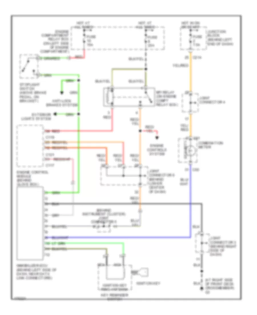
ANTI-THEFT Immobilizer Wiring Diagram, Evolution for Mitsubishi Lancer ES 2003 List of elements for Immobilizer Wiring Diagram, Evolution for Mitsubishi Lancer ES 2003: 33 (at right side of front deck crossmember) g3 (behind instrument cluster) joint connector 5 All times Anti-lock brakes system C01 C02 C117 C119 C121 C214 Combination meter Engine compartment relay box (on left side of engine compartment) Engine control module (behind glove box) Engine controls system Exterior lights system Fuse 15a Fuse 20a Fuse 7.5a Hot at Hot in on or start Ignition key Ignition key ring antenna Immobilizer-ecu (behind left side of dash, near data link connectors) Joint connector 3 (behind right side of dash) Joint connector 4 Joint connector 6 (behind lower center of dash) Junction block (behind left end of dash) Key reminder switch Mfi relay (on engine compt relay box) Nca Red Security Stoplight switch (above brake pedal, on bracket)
BODY CONTROL MODULES Body Control Modules Wiring Diagram, Evolution for Mitsubishi Lancer ES 2003 List of elements for Body Control Modules Wiring Diagram, Evolution for Mitsubishi Lancer ES 2003: 53 (at right side of front deck crossmember) g3 A10x A11x All times C210 C214 C217 C218 C226 C227 C228 Computer data lines system Dedicated fuse 13 10a Dedicated fuse 16 10a Dedicated fuse 17 10a Dedicated fuse 18 10a Dedicated fuse 19 10a Dedicated fuse 20 7.5a Dedicated fuse 21 7.5a Dedicated fuse 22 10a Dedicated fuse 23 10a Door locks system Engine compartment relay box (on left side of engine compartment) Engine compartment relay box (on left side of engine compartment) Etacs ecu Exterior lights system Front ecu G13 (at left front corner of engine compartment) G6 (behind center of dash, near left center reinforcement) Headlights system Headlights, wiper/washer, exterior lights systems Horns system Hot at Hot in Hot in on Interior lights system Interior lights, door locks systems Interior lights, power windows systems Joint connector 1 (behind center of dash) Joint connector 2 (behind instrument cluster) Joint connector 3 (behind right side of dash) Junction block (behind left end of dash) Multi- purpose fuse 14 15a Multi- purpose fuse 15 15a Multi- purpose fuse 2 7.5a On or acc Or start Pnk Power window relay Red Warning system Wiper/ washer system Wiper/washer system Body Control Modules Wiring Diagram, Except Evolution for Mitsubishi Lancer ES 2003 List of elements for Body Control Modules Wiring Diagram, Except Evolution for Mitsubishi Lancer ES 2003: 53 A10x A11x All times C210 C214 C217 C218 C226 C227 C228 Computer data lines system Dedicated fuse 13 10a Dedicated fuse 16 10a Dedicated fuse 17 10a Dedicated fuse 18 10a Dedicated fuse 19 10a Dedicated fuse 20 7.5a Dedicated fuse 21 7.5a Dedicated fuse 22 10a Dedicated fuse 23 10a Door locks system Engine compartment relay box (on left side of engine compartment) Engine compartment relay box (on left side of engine compartment) Etacs ecu Exterior lights system Front ecu G13 (at left front corner of engine compartment) G3 (at right side of front deck crossmember) Headlights system Headlights sytem Headlights, wiper/washer, exterior lights systems Horns system Hot at Hot in Hot in on Interior lights system Interior lights, door locks systems Interior lights, door locks systems Joint connector 1 (behind center of dash) Joint connector 2 (behind instrument cluster) Joint connector 3 (behind right side of dash) Junction block (behind left end of dash) Multi- purpose fuse 14 15a Multi- purpose fuse 15 15a Multi- purpose fuse 2 7.5a On or acc Or start Pnk Power tops system Power window relay Red Warning system Wiper/washer system
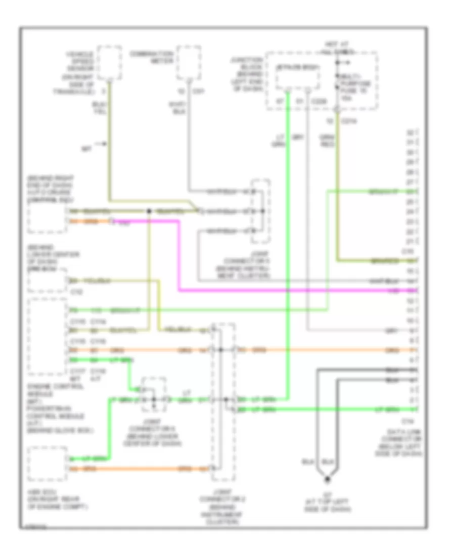
COMPUTER DATA LINES Computer Data Lines Wiring Diagram, Evolution for Mitsubishi Lancer ES 2003 List of elements for Computer Data Lines Wiring Diagram, Evolution for Mitsubishi Lancer ES 2003: 25 (behind instrument cluster) (on right side of transaxle) Abs ecu (on right rear of engine compt) C01 C115 C117 C12 C14 C15 C214 C228 Combination meter Data link connector (below left side of dash) Engine control module (behind glove box) Etacs ecu Fuse 15a G7 (at top left side of dash) Hot at all times Joint connector 2 Joint connector 4 Joint connector 5 (behind instrument cluster) Joint connector 6 (behind lower center of dash) Junction block (behind left end of dash) Srs ecu (behind lower center of dash) Vehicle speed sensor Computer Data Lines Wiring Diagram, Except Evolution for Mitsubishi Lancer ES 2003 List of elements for Computer Data Lines Wiring Diagram, Except Evolution for Mitsubishi Lancer ES 2003: 29 (behind instrument cluster) (behind lower center of dash) srs ecu (behind right end of dash) auto cruise control ecu (on right side of transaxle) Abs ecu (on right rear of engine compt) C01 C114 C115 C116 C116 a/t C117 C12 C14 C15 C214 C228 Combination meter Data link connector (below left side of dash) Engine control module (m/t) powertrain control module (a/t) (behind glove box) Etacs ecu G7 (at top left side of dash) Hot at all times Joint connector 2 Joint connector 5 (behind instru- ment cluster) Joint connector 6 (behind lower center of dash) Junction block (behind left end of dash) M/t Multi- purpose fuse 15 15a Vehicle speed sensor
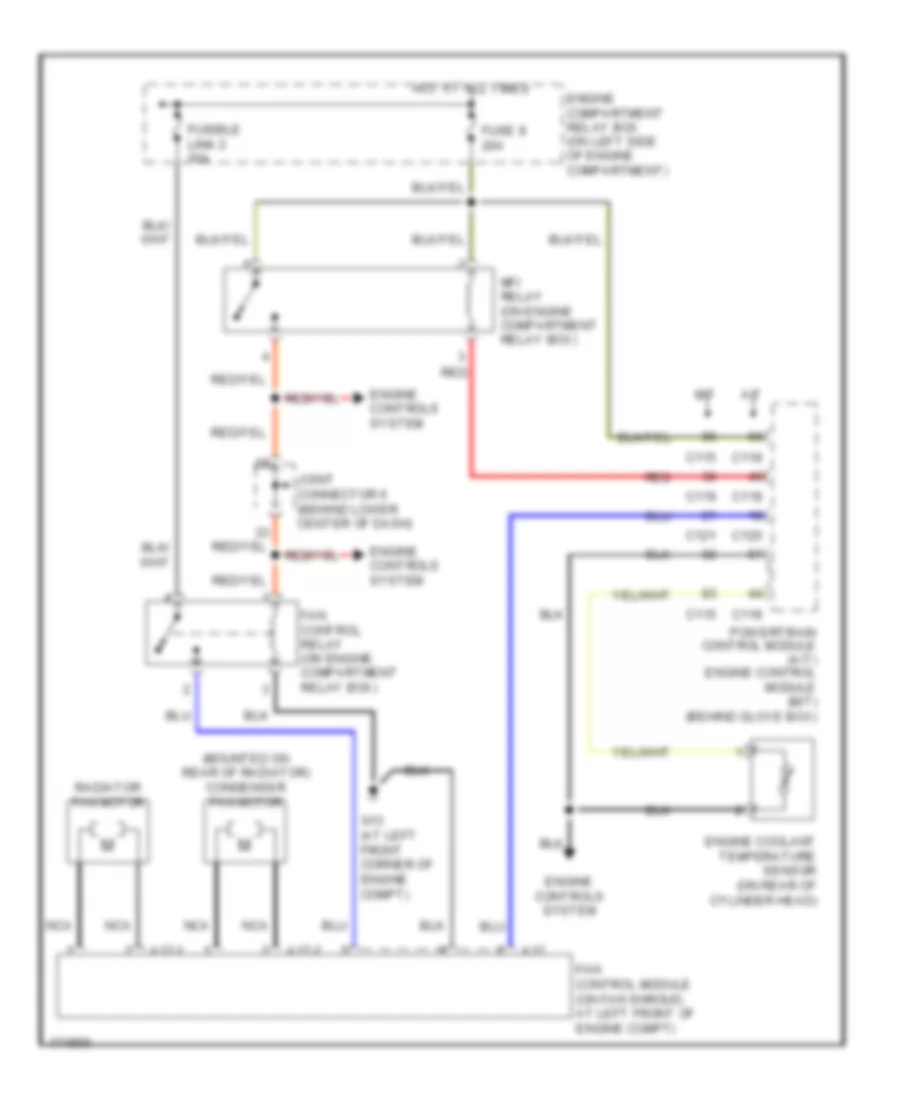
COOLING FAN Cooling Fan Wiring Diagram, Evolution for Mitsubishi Lancer ES 2003 List of elements for Cooling Fan Wiring Diagram, Evolution for Mitsubishi Lancer ES 2003: 33 (mounted on rear of radiator) A17 A17-1 A34 A35 C115 C119 C121 C210 Condenser fan motor Condenser fan relay (hi) (on engine compt relay box) Condenser fan relay (lo) (on engine compt relay box) Cooling fan motor Engine compartment relay box (on left side of engine compt) Engine control module (behind glove box) Engine controls system Engine coolant temperature sensor (on rear of cylinder head) Fan control module (on fan shroud, at left front of engine compt) Fan control relay (on engine compartment relay box) Fuse 11 30a Fuse 25 30a Fuse 5 7.5a Fuse 8 20a Fusible link 2 50a G13 (at left front corner of engine compt) Headlights, exterior lights & wiper/washer systems Hot in all times Hot in on Joint connector 2 (behind instrument cluster) Joint connector 6 (behind lower center of dash) Mfi relay (on engine compartment relay box) Nca Red Cooling Fan Wiring Diagram, Except Evolution for Mitsubishi Lancer ES 2003 List of elements for Cooling Fan Wiring Diagram, Except Evolution for Mitsubishi Lancer ES 2003: 26 (mounted on rear of radiator) condenser fan motor A/t A17 A17-1 A17-2 C115 C118 C119 C120 C121 Engine compartment relay box (on left side of engine compartment) Engine controls system Engine coolant temperature sensor (on rear of cylinder head) Fan control module (on fan shroud, at left front of engine compt) Fan control relay (on engine compartment relay box) Fuse 8 20a Fusible link 2 50a G13 (at left front corner of engine compt) Hot at all times Joint connector 6 (behind lower center of dash) M/t Mfi relay (on engine compartment relay box) Nca Powertrain control module (a/t) engine control module (m/t) (behind glove box) Radiator fan motor Red
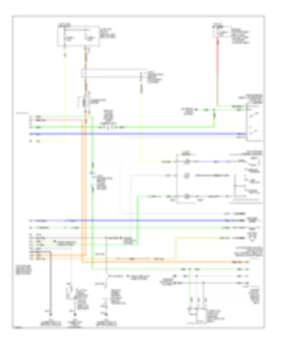
CRUISE CONTROL Cruise Control Wiring Diagram, A/T for Mitsubishi Lancer ES 2003 List of elements for Cruise Control Wiring Diagram, A/T for Mitsubishi Lancer ES 2003: 43 (behind lower center of dash) joint connentor 6 Auto cruise control ecu (behind right end of dash) Auto cruise control switch Auto-cruise control vacuum pump (2.0l: on right front of engine compartment) C01 C02 C114 C116 C118 C120 C204 C214 C229 Cancel Clock spring Combination meter Computer data lines system Control valve Cruise Engine compartment relay box (on left side of engine compartment) Engine controls system Exterior lights system Fuse 10 15a Fuse 2 7.5a Fuse 4 7.5a G14 (under front of center console) Hot at all times Hot in on or start Joint connectior 5 (behind instrument cluster) Joint connector 6 (behind lower center of dash) Junction block (behind left end of dash) Main Nca Off Output shaft speed sensor (2.0l: on top right of transaxle) Powertrain control module (behind glove box) Red Release valve Resume Set Starting/ charging system Stoplight switch (above brake pedal, on bracket) Throttle position sensor (on throttle body) Cruise Control Wiring Diagram, M/T for Mitsubishi Lancer ES 2003 List of elements for Cruise Control Wiring Diagram, M/T for Mitsubishi Lancer ES 2003: 41 (above brake pedal, on bracket) stoplight switch (behind lower center of dash) joint connector 6 Auto cruise control ecu (behind right end of dash) Auto cruise control switch Auto-cruise control vacuum pump (2.0l: on right front of engine compartment) C01 C02 C115 C204 C214 C229 Cancel Clock spring Clutch pedal position switch (above clutch pedal on bracket) Combination meter Computer data lines system Control valve Cruise Engine compartment relay box (on left side of engine compartment) Engine control module (behind glove box) Engine controls system Exterior lights system Fuse 10 15a Fuse 2 7.5a Fuse 4 7.5a G14 (under front of center console) G15 (under left front kick panel) Hot at all times Hot in on or start Joint connector 5 (behind instrument cluster) Joint connector 6 (behind lower center of dash) Junction block (behind left end of dash) Main Nca Off Red Release valve Resume Set Throttle position sensor (on throttle body) Vehicle speed sensor (on right side of transaxle)
DEFOGGERS Defoggers Wiring Diagram for Mitsubishi Lancer ES 2003 List of elements for Defoggers Wiring Diagram for Mitsubishi Lancer ES 2003: 19 A/c ecu (behind center of dash, below radio) C214 C217 Defogger Defogger relay F16 G3 (at right side of front deck crossmember) Heat print Hot at all times Hot in run Interior lights system Junction block (behind left end of dash) Left remote controlled mirror Multi- purpose fuse 20 30a Multi- purpose fuse 5 7.5a Multi- purpose fuse 6 7.5a Nca Right remote controlled mirror W/ heated mirrors
ENGINE PERFORMANCE
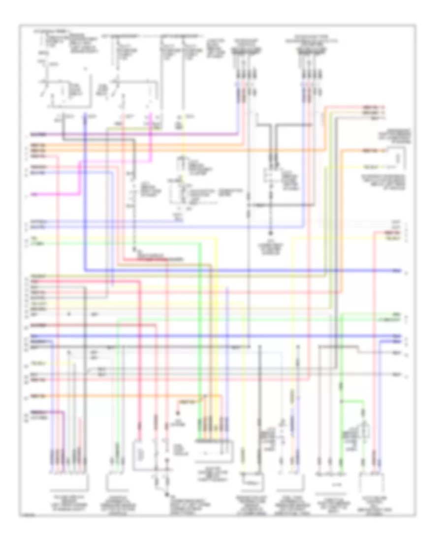
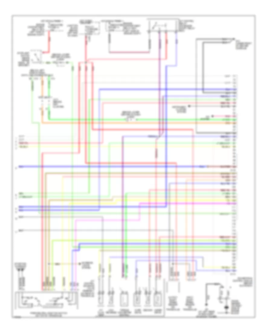
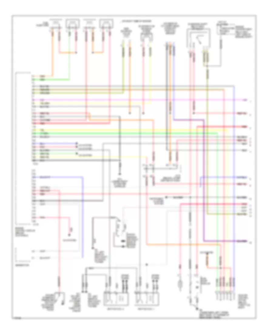
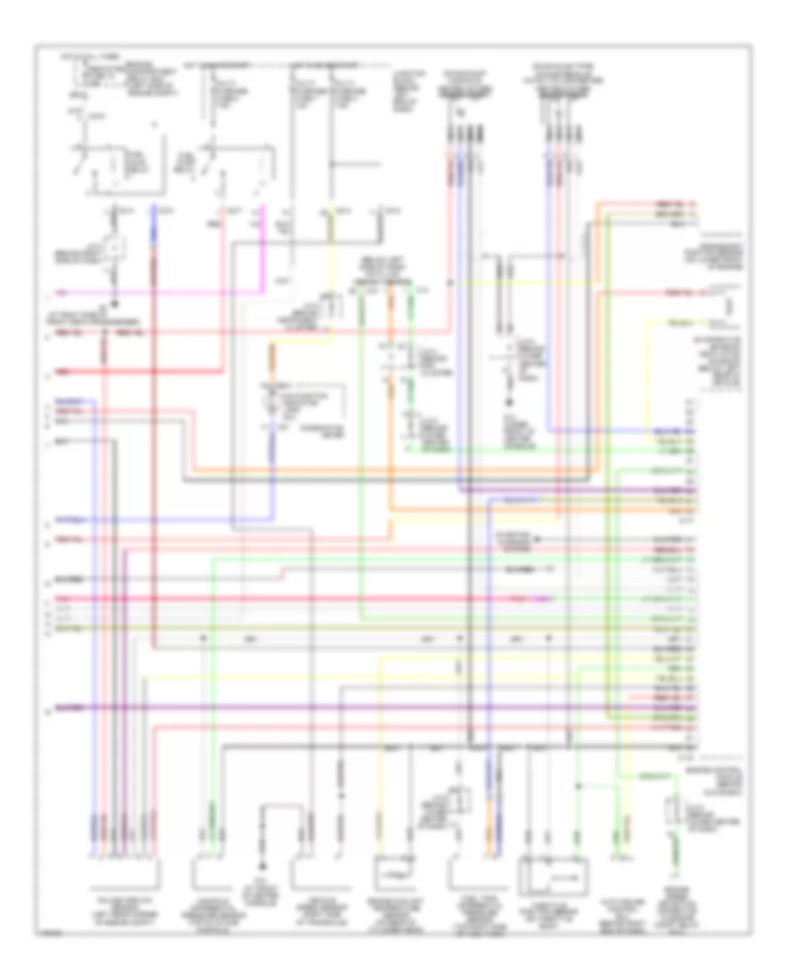
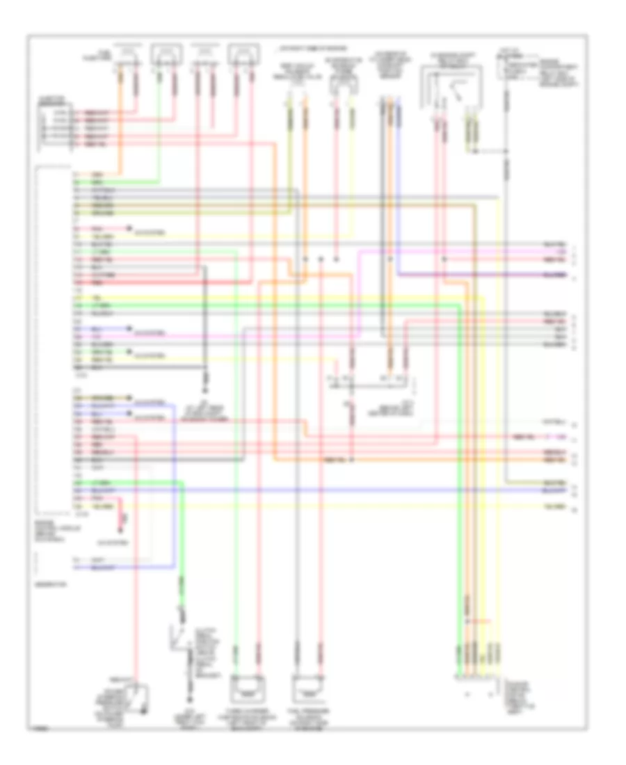
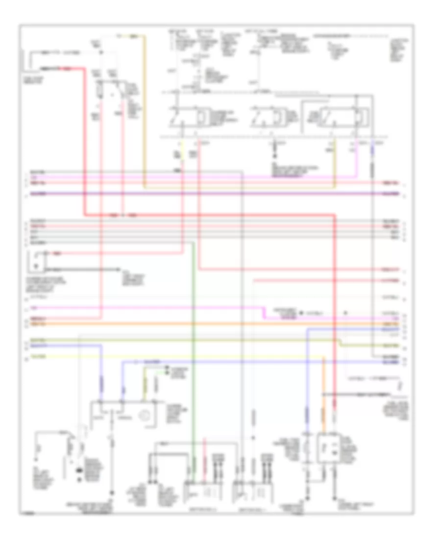
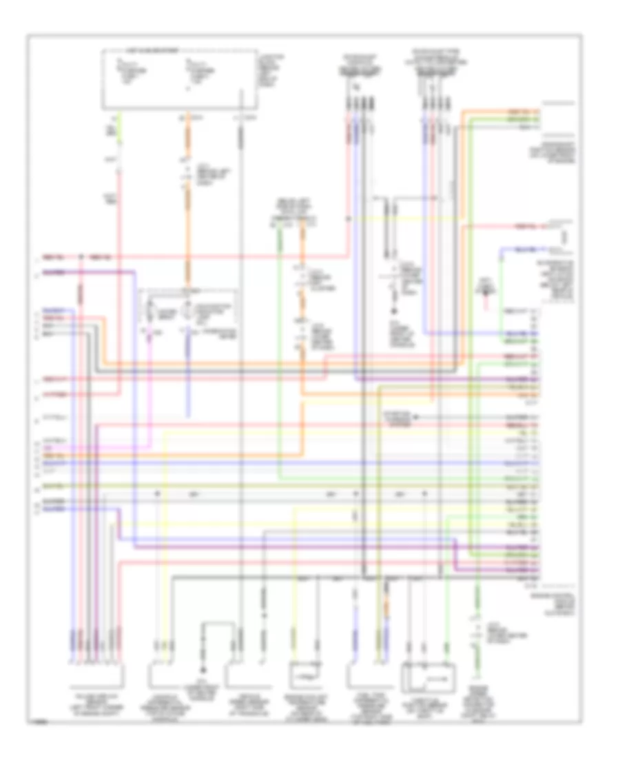
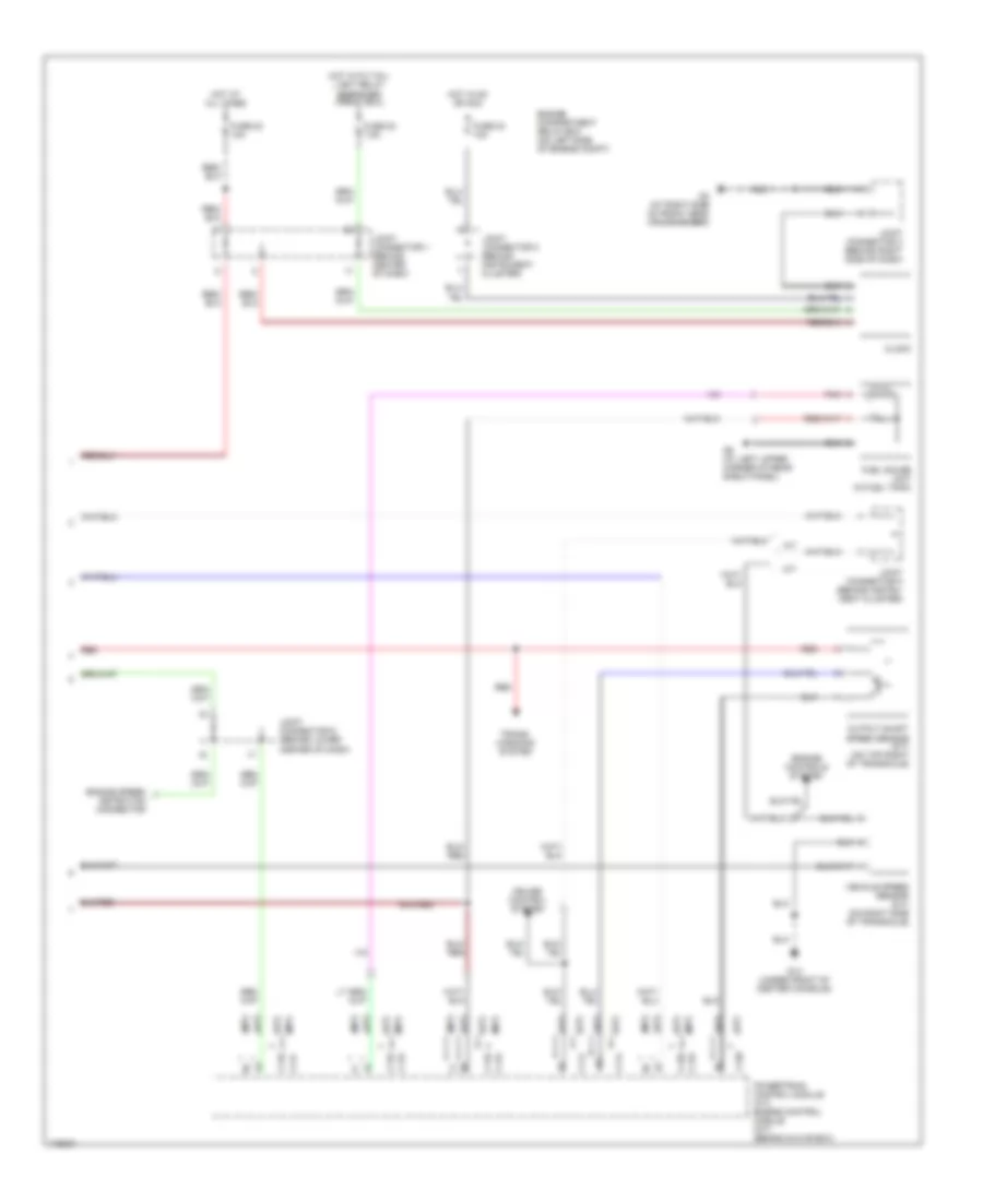
2.0L 2.0L, Engine Performance Wiring Diagram, with A/T (1 of 3) for Mitsubishi Lancer ES 2003 List of elements for 2.0L, Engine Performance Wiring Diagram, with A/T (1 of 3) for Mitsubishi Lancer ES 2003: 29 (behind lower center of dash) j/c 6 (on engine compt relay box) mfi relay (on rear of cylinder head) camshaft position sensor (right side of engine) A/c system C118 C120 Dedicated fuse 3 20a Egr solenoid valve Engine compartment relay box (left side of engine compt) Engine speed detection connector (in engine compt relay box) Evaporative emission purge solenoid Fuel injectors G11 (left side of cylinder head, under throttle cable) G14 (under front of center console) G4 (at left rear of engine compt, on shock tower) Generator Hot at all times Ignition coil 1 Ignition coil 2 Instrument cluster system J/c 6 (behind lower center of dash) Nca Pnk Power steering oil pressure switch (on power steering pump) Powertrain control module (behind glove box) Red Spark plugs Starting/ charging system 2.0L, Engine Performance Wiring Diagram, with A/T (2 of 3) for Mitsubishi Lancer ES 2003 List of elements for 2.0L, Engine Performance Wiring Diagram, with A/T (2 of 3) for Mitsubishi Lancer ES 2003: 38 (on exhaust manifold) heated oxygen sensor (front) (on exhaust pipe, downstream of catalytic converter) heated oxygen sensor (rear) A/c system Auto cruise control ecu (behind right end of dash) C01 C210 C214 C217 Combination meter Crankshaft position sensor (on lower front of engine) Dedicated fuse 15 15a Engine compartment relay box (left side of engine compt) Engine coolant temperature sensor (on rear of cylinder head) Evaporative emission ventilation solenoid (below left rear of vehicle) Fuel pump module Fuel pump relay Fuel tank differential pressure sensor (on top right side of fuel tank) G14 (under front of center console) G3 (right side of frt deck crossmember) G9 (under rear seat back, at left upper corner of rear shelf panel) Hot at all times Hot in on or start Idle air control motor (below throttle body) J/c 3 (behind right side of dash) J/c 5 (behind instrument cluster J/c 6 (behind center lower of dash) J/c 6 (behind lower center of dash) Junction block (behind left side of dash) Malfunction indicator lamp (mil) Manifold differential pressure sensor (on top of intake manifold) Multi- purpose fuse 1 10a Multi- purpose fuse 2 7.5a Multi- purpose fuse 8 7.5a Nca Pnk Red Throttle position sensor (on throttle body) Volume airflow sensor (left rear corner of engine compt) 2.0L, Engine Performance Wiring Diagram, with A/T (3 of 3) for Mitsubishi Lancer ES 2003 List of elements for 2.0L, Engine Performance Wiring Diagram, with A/T (3 of 3) for Mitsubishi Lancer ES 2003: 37 (behind lower center of dash) j/c 6 (below left side of dash) data link connector (dlc) A/c system A/t control relay (on engine compt relay box) A/t control solenoid valve assembly (on rear of transaxle) A/t fluid temp C114 C116 C14 C15 C210 Dedicated fuse 10 15a Dedicated fuse 14 20a Engine compartment relay box (left side of engine compt) Exterior lights system G14 (under front of center console) G4 (at left rear of eng compt, on shock tower) Hot at all times Hot in run or start Input shaft speed sensor (on transaxle) Instrument cluster system J/c 2 (behind inst cluster) Junction block (behind left end of dash) Knock sensor (on right side of engine block) Low/ reverse Multi- purpose fuse 3 7.5a Output shaft speed sensor (on transaxle) Over drive Park/neutral position switch (on top of transaxle) Pnk Powertrain control module (behind glove box) Red Second Starting/ charging system Stoplight switch (above brake pedal, on bracket) Torque converter control Under drive 2.0L, Engine Performance Wiring Diagram, with M/T (1 of 2) for Mitsubishi Lancer ES 2003 List of elements for 2.0L, Engine Performance Wiring Diagram, with M/T (1 of 2) for Mitsubishi Lancer ES 2003: 30 (in engine compt relay box) mfi relay (on rear of cylinder head) camshaft position sensor (on right side of engine) A/c system C119 C121 Dedicated fuse 8 20a Egr solenoid valve Engine compartment relay box (left side of engine compt) Engine control module (behind glove box) Evaporative emission purge solenoid Fuel injectors Fuel pump module G11 (on left side of cylinder head, under throttle cable) G14 (under front of center console) G4 (at left rear of eng compt, on shock tower) G9 (under rear left upper seat back, at corner of rear shelf panel) Generator Hot at all times Idle air control motor (below throttle body) Ignition coil 1 Ignition coil 2 Instrument cluster system J/c 6 (behind lower center of dash) Knock sensor (on right side of engine block) Nca Pnk Power steering pressure switch (on power steering pump) Red Spark plugs 2.0L, Engine Performance Wiring Diagram, with M/T (2 of 2) for Mitsubishi Lancer ES 2003 List of elements for 2.0L, Engine Performance Wiring Diagram, with M/T (2 of 2) for Mitsubishi Lancer ES 2003: 46 (below left side of dash) data link connector (dlc) (on exhaust manifold) heated oxygen sensor (front) (on exhaust pipe, downstream of catalytic converter) heated oxygen sensor (rear) Auto cruise control ecu (behind right end of dash) C01 C115 C117 C14 C15 C210 C214 C217 Combination meter Crankshaft position sensor (on lower front of engine) Dedicated fuse 15 15a Engine compartment relay box (left side of engine compt) Engine control module (behind glove box) Engine coolant temperature sensor (on rear of cylinder head) Engine speed detection connector (in engine compt relay box) Evaporative emission ventilation solenoid (below left rear of vehicle) Front deck crossmember) Fuel pump relay Fuel tank differential pressure sensor (top right side of fuel tank) G14 (at front of center console) G14 (under front of center console) G3 (at right side of Hot at all times Hot in on or start J/c 2 (behind inst cluster) J/c 3 (behind right side of dash) J/c 5 (behind instrument cluster) J/c 6 (behind lower center of dash) J/c 6 (behind lower center of dash) Junction block (behind left end of dash) Malfunction indicator lamp (mil) Manifold differential pressure sensor (top of intake manifold) Multi- purpose fuse 1 10a Multi- purpose fuse 2 7.5a Multi- purpose fuse 8 7.5a Nca Pnk Red Starting/ charging system Throttle position sensor (on throttle body) Vehicle speed sensor (right side of transaxle) Volume airflow sensor (left rear corner of engine compt)
2.0L TURBO 2.0L Turbo, Engine Performance Wiring Diagram (1 of 3) for Mitsubishi Lancer ES 2003 List of elements for 2.0L Turbo, Engine Performance Wiring Diagram (1 of 3) for Mitsubishi Lancer ES 2003: 27 (in engine compt relay box) mfi relay (on rear of cylinder head) camshaft position sensor (on right side of engine) A/c system C119 C121 Clutch pedal position switch (above nca Clutch pedal, on bracket) Dedicated fuse 8 20a Egr vacuum solenoid regulator valve Engine compartment relay box (left side of engine compt) Engine control module (behind glove box) Evaporative emission purge solenoid Fuel injectors Fuel pressure solenoid (on right side of engine) G15 (under left front kick panel) G4 (at left rear of eng compt, on shock tower) Generator Hot at all times Idle air control motor (below throttle body) Injector resistor J/c 4 (behind left center of dash) Nca Pnk Power steering pressure switch (on power steering pump) Red Turbo charger wastegate solenoid (left front of eng compt) 2.0L Turbo, Engine Performance Wiring Diagram (2 of 3) for Mitsubishi Lancer ES 2003 List of elements for 2.0L Turbo, Engine Performance Wiring Diagram (2 of 3) for Mitsubishi Lancer ES 2003: 38 Auto C209 C210 C214 Charge air cooler water spray motor (left front of engine compt) Charge air cooler water spray relay Charge air cooler water spray switch Dedicated fuse 15 15a Engine compartment relay box (left side of engine compt) Fuel level sensor (sub) (on top right side of fuel tank) Fuel pump & level sensor (main) (in fuel tank) Fuel pump relay Fuel pump relay (at right side of fire- wall) Fuel pump resistor Fuel tank temperature sensor (on top of fuel tank) G11 (at rear of engine, below cylinder head) G13 (left front corner of eng compt) G15 (under left front kick panel) G2 (under right front kick panel) G4 (at left rear of eng compt, on shock tower) G6 (behind center of dash, near left center reinforcement) Hot at all times Hot in on Hot in on or start Ignition coil 1 Ignition coil 2 Instrument cluster system Interior lights system J/c 2 (behind instrument cluster) Junction block (behind left end of dash) Knock sensor (on right side of engine block) Manual Multi- purpose fuse 23 10a Multi- purpose fuse 5 7.5a Multi- purpose fuse 8 7.5a Nca Red Spark plugs 2.0L Turbo, Engine Performance Wiring Diagram (3 of 3) for Mitsubishi Lancer ES 2003 List of elements for 2.0L Turbo, Engine Performance Wiring Diagram (3 of 3) for Mitsubishi Lancer ES 2003: 36 (below left side of dash) data link connector (dlc) (on exhaust manifold) heated oxygen sensor (front) (on exhaust pipe, downstream of catalytic converter) heated oxygen sensor (rear) Anti theft system C01 C02 C115 C117 C14 C15 C210 C214 Combination meter Crankshaft position sensor (on lower front of engine) Engine control module (behind glove box) Engine coolant temperature sensor (on rear of cylinder head) Engine speed detection connector (in engine compt relay box) Evaporative emission ventilation solenoid (below left rear of vehicle) Fuel tank differential pressure sensor (top right side of fuel tank) G14 (under front of center console) Hot in on or start J/c 2 (behind inst cluster) J/c 4 (behind left center of dash) J/c 6 (behind lower center of dash) J/c 6 (behind lower center of dash) Junction block (behind left end of dash) Malfunction indicator lamp (mil) Manifold differential pressure sensor (top of intake manifold) Multi- purpose fuse 1 10a Multi- purpose fuse 2 7.5a Nca Starting/ charging system Throttle position sensor (on throttle body) Vehicle speed sensor (right side of transaxle) Volume airflow sensor (left front corner of engine compt) Water spray
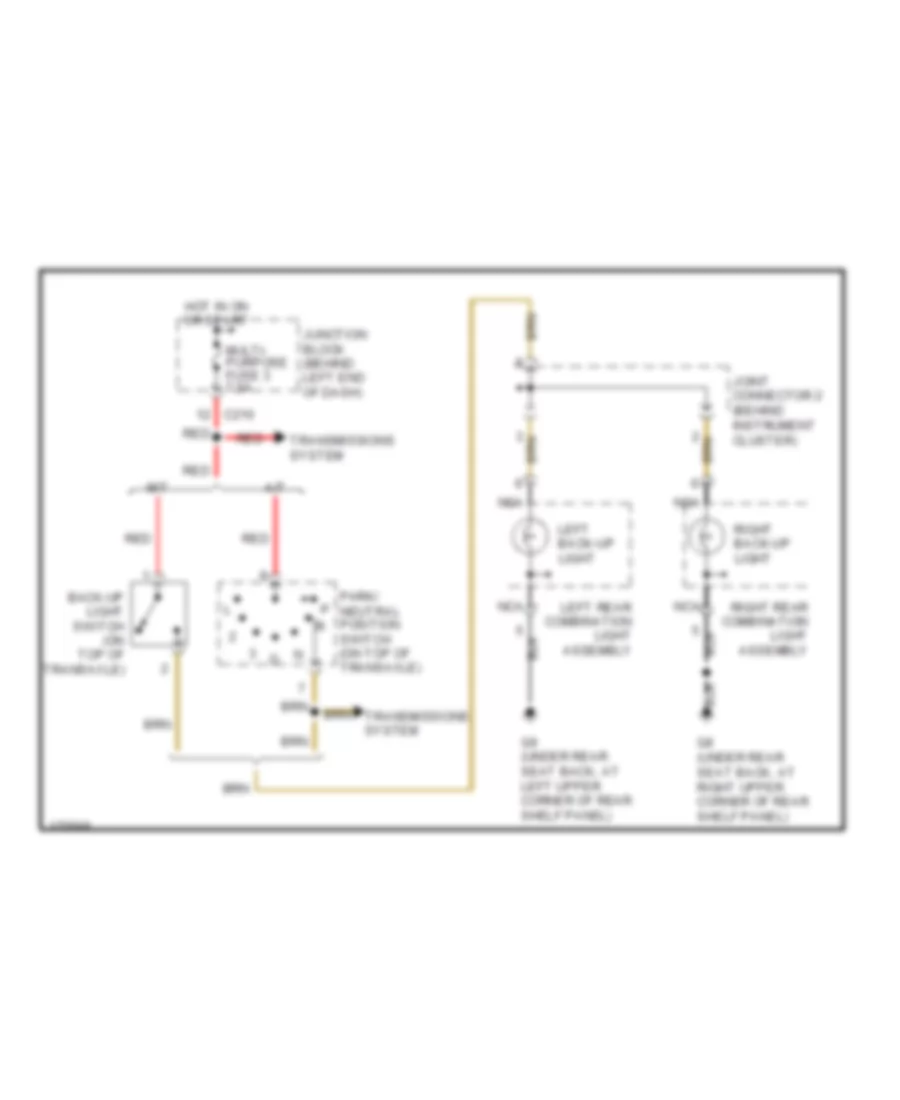
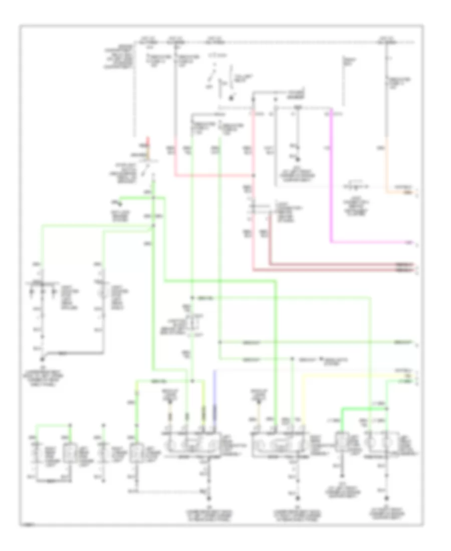
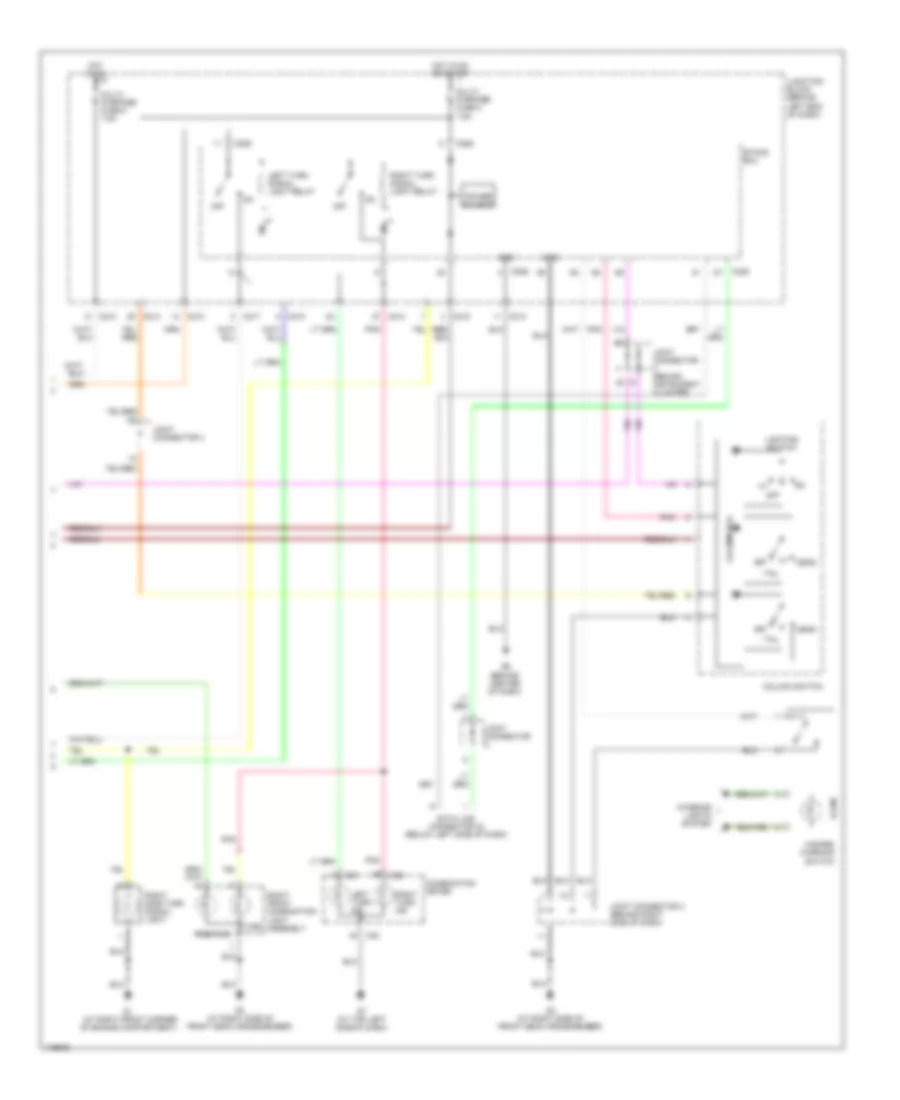
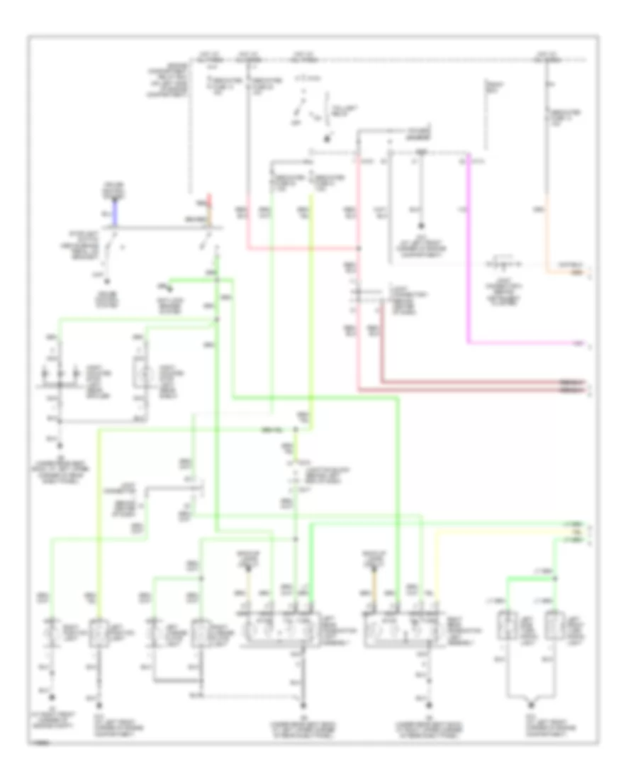
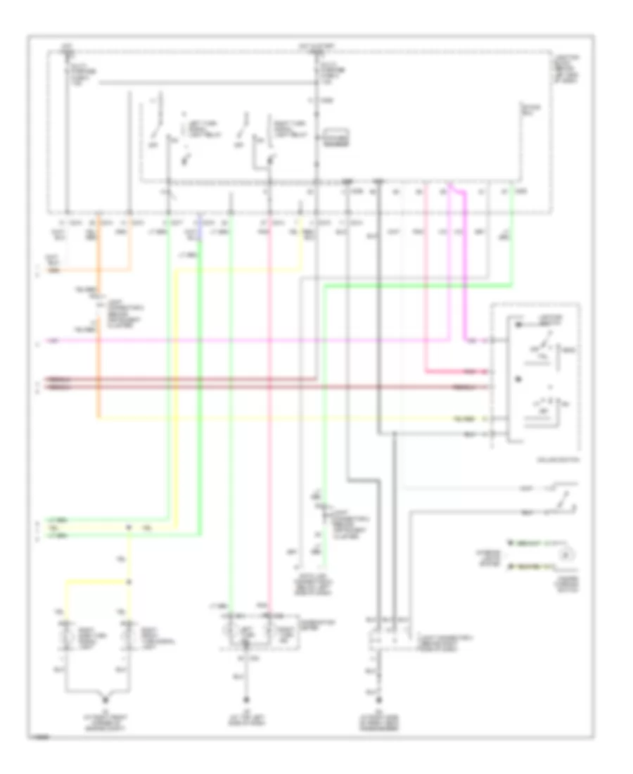
EXTERIOR LIGHTS Back-up Lamps Wiring Diagram, Evolution for Mitsubishi Lancer ES 2003 List of elements for Back-up Lamps Wiring Diagram, Evolution for Mitsubishi Lancer ES 2003: 14 Back-up light switch (on top of transaxle) C210 G8 (under rear seat back, at right upper corner of rear shelf panel) G9 (under rear seat back, at left upper corner of rear shelf panel) Hot in run or start Joint connector 4 Junction block (behind left end of dash) Left back-up light Left rear combination light Multi- purpose fuse 3 7.5a Nca Red Right back-up light Right rear combination light Back-up Lamps Wiring Diagram, Except Evolution for Mitsubishi Lancer ES 2003 List of elements for Back-up Lamps Wiring Diagram, Except Evolution for Mitsubishi Lancer ES 2003: 18 A/t Back-up light switch (on top of transaxle) C210 G8 (under rear seat back, at right upper corner of rear shelf panel) G9 (under rear seat back, at left upper corner of rear shelf panel) Hot in on or start Joint connector 2 (behind instrument cluster) Junction block (behind left end of dash) Left back-up light Left rear combination light assembly M/t Multi- purpose fuse 3 7.5a Nca Park/ neutral position switch (on top of transaxle) Red Right back-up light Right rear combination light assembly Transmissions system Exterior Lamps Wiring Diagram, Evolution (1 of 2) for Mitsubishi Lancer ES 2003 List of elements for Exterior Lamps Wiring Diagram, Evolution (1 of 2) for Mitsubishi Lancer ES 2003: 43 A10x A11x Anti-lock brakes system Back-up lamps circuit C210 C217 Dedicated fuse 10 15a Dedicated fuse 13 10a Dedicated fuse 20 7.5a Dedicated fuse 21 7.5a Dedicated fuse 22 10a Engine compartment relay box (on left side of engine compartment) Front ecu G1 (at right front corner of engine compartment) G13 (at left front corner of engine compartment) G8 (under rear seat back, at right upper corner of rear shelf panel) G9 (under rear seat back, at left upper corner of rear shelf panel) Gnd Headlights system Hight mounted stop light (rear shelf) Hight mounted stop light (rear spoiler) Hot at all times Joint connector 1 (behind center of dash) Joint connector 2 (behind instrument cluster) Junction block (behind left end of dash) Left front combi- nation assembly Left license plate light Left rear combination light assembly turn Left rear side marker light Left side turn signal light Nca Off Position Power source Red Right license plate light Right rear combination light assembly turn Right rear side marker light Stop Stoplight switch (above brake pedal, on bracket) Tail Taillight relay Turn Exterior Lamps Wiring Diagram, Evolution (2 of 2) for Mitsubishi Lancer ES 2003 List of elements for Exterior Lamps Wiring Diagram, Evolution (2 of 2) for Mitsubishi Lancer ES 2003: 43 (at right front corner of engine compartment) C01 C02 C210 C214 C217 C226 C228 Column switch Column-ecu Combination meter Data link connector (2) (below left side of dash) Etacs ecu G3 (at right side of front deck crossmember) G6 (behind center of dash) G7 (at top left side of dash) Gnd Hazard warning switch Head Hot in on Hot in on or start Illum Interior lights system Joint connector Joint connector (behind instrument cluster) Joint connector 3 (behind right side of dash) Joint connector 4 Junction block (behind left end of dash) Left turn ind Left turn signal light relay Lighting switch Multi- purpose fuse 2 7.5a Multi- purpose fuse 5 7.5a Off Pnk Position Power source Right front combination light assembly Right side turn signal light Right turn ind Right turn signal light relay Tail Turn Exterior Lamps Wiring Diagram, Except Evolution (1 of 2) for Mitsubishi Lancer ES 2003 List of elements for Exterior Lamps Wiring Diagram, Except Evolution (1 of 2) for Mitsubishi Lancer ES 2003: 43 A10x A11x Anti-lock brakes system Back-up lamps circuit C210 C217 Cruise control system Dedicated fuse 10 15a Dedicated fuse 13 10a Dedicated fuse 20 7.5a Dedicated fuse 21 7.5a Dedicated fuse 22 10a Engine compartment relay box (on left side of engine compartment) Front ecu G1 (at right front corner of engine compt) G13 (at left front corner of engine compartment) G8 (under rear seat back, at right upper corner of rear shelf panel) G9 (under rear seat back, at left upper corner of rear shelf panel) Gnd Hight mounted stop light (rear shelf) Hight mounted stop light (rear spoiler) Hot at all times Joint connector (behind center of dash) Joint connector 1 (behind center of dash) Joint connector 2 (behind instrument cluster) Junction block (behind left end of dash) Left front turn signal light Left license plate light Left position light Left rear combination light assembly Left side turn signal light Nca Off Power source Red Right license plate light Right position light Right rear combination light assembly Stop Stoplight switch (above brake pedal, on bracket) Tail Taillight relay Turn Exterior Lamps Wiring Diagram, Except Evolution (2 of 2) for Mitsubishi Lancer ES 2003 List of elements for Exterior Lamps Wiring Diagram, Except Evolution (2 of 2) for Mitsubishi Lancer ES 2003: 37 C01 C02 C210 C214 C217 C226 C228 Column switch Combination meter Data link connector (2) (below left side of dash) Etacs ecu G1 (at right front corner of engine compt) G3 (at right side of front deck crossmember) G7 (at top left side of dash) Gnd Hazard warning switch Head Hot in on Hot in start or on Interior lights system Joint connector 2 (behind instrument cluster) Joint connector 3 (behind right side of dash) Joint connector 5 (behind instrument cluster) Junction block (behind left end of dash) Left turn ind Left turn signal light relay Lighting switch Multi- purpose fuse 2 7.5a Multi- purpose fuse 5 7.5a Off Pnk Power source Right front turn signal light Right side turn signal light Right turn ind Right turn signal light relay Tail
GROUND DISTRIBUTION Ground Distribution Wiring Diagram for Mitsubishi Lancer ES 2003 List of elements for Ground Distribution Wiring Diagram for Mitsubishi Lancer ES 2003: 30 A/c ecu, abs warning light relay, blower relay, cigarette lighter, clock, column ecu, column switch, etacs ecu, fuel pump relay 1, key reminder switch, left door lock key cylinder switch, power window relay, left front door lock actuator, power window main switch, power window sub switch, remote controlled mirror switch, right door lock key cylinder switch, left remote controlled mirror, right remote controlled mirror Abs ecu, auto-cruise control ecu, brake fluid level switch, engine control module, heated oxygen sensor shields, powertrain control module, vehicle speed sensor, windshield wiper motor Battery Blower motor Clutch pedal position switch, starter relay interlock switch Connector lock switch Data link connector, combination meter, rheostat Drl ecu, fan controller, fan control relay, front ecu, left side turn signal light, left front turn signal light, left position light, left headlight Fuel pump, fuel gauge unit, license plate lights, left rear combination light assembly, G1 (right front corner of engine compartment) G10 (evolution) (at lower left rear of engine) G10 (except evolution) (at rear of cylinder head) G11 (evolution) (at rear of engine, below cylinder head) G11 (except evolution) (on left side of cylinder head, under throttle cable) G12 (at left front of engine compartment, left of battery) G13 (at left front corner of engine compartment) G14 (under front of center console) G15 (under left front kick panel) G16 (behind center of dash, on right dash support) G3 (at right side of front deck crossmember) G4 (at left rear of engine compartment, on shock tower) G6 (behind center of dash, near left center reinforcement) G7 (at top left side of dash) G8 (at right upper corner of rear shelf panel) G9 (at left upper corner of rear shelf panel) Ignition coil 1, ignition coil 2 Ignition coil 1, ignition coil 2, knock sensor shield Rear shelf high mounted stoplight, rear spoiler high mounted stoplight, rear wiper motor Right headlight, right position light, right side turn signal light, right front turn signal light, windshield washer motor, rear washer motor Right rear combination light assembly, sunroof motor assembly, sunroof switch
HEADLIGHTS Headlights Wiring Diagram, Evolution for Mitsubishi Lancer ES 2003 List of elements for Headlights Wiring Diagram, Evolution for Mitsubishi Lancer ES 2003: 76 (at left front corner of engine compartment) (at right front corner of engine compartment) (at right side of front deck crossmember) (at right side of front deck crossmember) g3 (at top left side of dash) (behind center of dash, near left center reinforcement) g6 A10x A11x Air conditioning system Beam ind C01 C02 C210 C214 C217 C226 C228 Column switch Column-ecu Combination meter Computer data lines system Controller discharge Dedicated fuse 16 10a Dedicated fuse 17 10a Dedicated fuse 18 20a Dedicated fuse 19 20a Dedicated fuse 20 7.5a Dimmer/ passing switch Discharge bulb Discharge controller Engine compartment relay box (on left side of engine compt) Etacs ecu Fog ind Foglight relay (on engine compt relay box) Foglight switch Front ecu Front ecu (in engine compt relay box) Fuse 10a Fuse 15a G1 (at right front corner of engine compt) G13 G13 (at left front corner of engine compt) G3 (at right side of front deck crossmember) Head Headlight relay high Headlight relay low Hot at all times Hot in on Hot in on or start Ill Interior lights system Joint conn- ector 2 (behind instru- ment cluster) Joint conne- ctor 2 (behind instru- ment cluster) Joint connector (behind center of dash) Joint connector (behind right side of dash) Joint connector 1 (behind center of dash) Joint connector 3 (behind right side of dash) Joint connector 4 Junction block (behind left end of dash) Left foglight Left front combination light assembly Left front door switch Left headlight Lighting switch Multi- purpose fuse 2 7.5a Multi- purpose fuse 5 7.5a Nca Off Pass Pnk Red Right foglight Right front combination light assembly Right headlight Tail Taillight relay Headlights Wiring Diagram, with DRL, Except Evolution for Mitsubishi Lancer ES 2003 List of elements for Headlights Wiring Diagram, with DRL, Except Evolution for Mitsubishi Lancer ES 2003: 54 (at right side of front deck crossmember) g3 A10x A11x Beam C01 C210 C214 C217 C226 C228 Column switch Column-ecu Combination meter Computer data lines system Dedicated fuse 16 10a Dedicated fuse 17 10a Dedicated fuse 18 10a Dedicated fuse 19 10a Dedicated fuse 22 10a Dedicated fuse 25 15a Dimmer/ passing switch Drl ecu (at left front corner of engine compartment) Engine compartment relay box (on left side of engine compt) Etacs ecu Front ecu Front ecu (in engine compt relay box) G1 (at right front corner of engine compt) G13 (at left front corner of engine compt) G3 (at right side of front deck crossmember) Gnd Head Headlight relay high Headlight relay low Hot at all times Hot in on Hot in on or start Interior lights system Joint conn- ector 2 (behind instru- ment cluster) Joint connector (behind center of dash) Joint connector (behind right side of dash) Joint connector 3 (behind right side of dash) Joint connector 5 (behind instrument cluster) Junction block (behind left end of dash) Left front door switch Left headlight Lighting switch Multi- purpose fuse 2 7.5a Multi- purpose fuse 5 7.5a Off Pass Pnk Red Right headlight Tail Headlights Wiring Diagram, without DRL, Except Evolution for Mitsubishi Lancer ES 2003 List of elements for Headlights Wiring Diagram, without DRL, Except Evolution for Mitsubishi Lancer ES 2003: 52 (at right side of front deck crossmember) g3 (behind instrument cluster) A10x A11x Beam C01 C210 C214 C217 C226 C228 Column switch Column-ecu Combination meter Computer data lines system Dedicated fuse 16 10a Dedicated fuse 17 10a Dedicated fuse 18 10a Dedicated fuse 19 10a Dedicated fuse 22 10a Dimmer/ passing switch Engine compartment relay box (on left side of engine compt) Etacs ecu Front ecu Front ecu (in engine compt relay box) G1 (at right front corner of engine compt) G13 (at left front corner of engine compt) G3 (at right side of front deck crossmember) Head Headlight relay high Headlight relay low Hot at all times Hot in on Hot in on or start Interior lights system Joint conn- ector 2 (behind instru- ment cluster) Joint connector (behind center of dash) Joint connector (behind right side of dash) Joint connector 3 (behind right side of dash) Joint connector 5 Junction block (behind left end of dash) Left front door switch Left headlight Lighting switch Multi- purpose fuse 2 7.5a Multi- purpose fuse 5 7.5a Off Pass Pnk Red Right headlight Tail
HORN Horn Wiring Diagram, Evolution for Mitsubishi Lancer ES 2003 List of elements for Horn Wiring Diagram, Evolution for Mitsubishi Lancer ES 2003: 13 (behind left center of front bumper fascia) (behind left end of front bumper fascia) Clock spring Dedicated fuse 7 10a Engine compartment relay box (on left side of engine compt) Horn (hi) Horn (lo) Horn relay (on engine compt relay box) Horn switch Hot at all times Joint connector 5 (behind instrument cluster) Nca Red Horn Wiring Diagram, Except Evolution for Mitsubishi Lancer ES 2003 List of elements for Horn Wiring Diagram, Except Evolution for Mitsubishi Lancer ES 2003: 10 Clock spring Dedicated fuse 7 10a Engine compartment relay box (on left side of engine compartment) Horn (hi) (behind left center of front bumper fascia) Horn (lo) (behind left center of front bumper fascia) Horn relay (on engine compt relay box) Horn switch Hot at all times Joint connector 2 (behind instrument cluster) Nca
INSTRUMENT CLUSTER Instrument Cluster Wiring Diagram (1 of 2) for Mitsubishi Lancer ES 2003 List of elements for Instrument Cluster Wiring Diagram (1 of 2) for Mitsubishi Lancer ES 2003: 50 (at top left side of dash) g7 A/t Abs ind Anti-lock brakes system Brake fluid level switch (on brake master cylinder reservoir) Brake ind C01 C02 C210 C214 Charge ind Combination meter Control circuit Cruise control system Cruise ind Door ind Engine coolant temperature gauge unit (on rear of cylinder head) Exterior lights system Exterior lights system Fuel gauge Fuel ind Fuse 2 7.5 Fuse 3 7.5a G14 (under front of center console) G7 (at top left side of dash) Headlights system High beam ind Hot in on or start Illumination Interior lights system Joint connector 5 (behind instru- ment cluster) Junction block (behind left end of dash) Left turn ind M/t Malfunction ind light Nca Odometer/trip Oil ind Oil pressure switch (w/ turbo) (on left rear of engine) (w/o turbo) (on right front of engine) Parking brake switch (at base of parking brake lever) Pnk Red Right turn ind Seat belt ind Speedometer Srs ind Starting/charging system Tachometer Temperature gauge Warning systems Instrument Cluster Wiring Diagram (2 of 2) for Mitsubishi Lancer ES 2003 List of elements for Instrument Cluster Wiring Diagram (2 of 2) for Mitsubishi Lancer ES 2003: 37 (a/t) (m/t) A/t C114 C115 C117 C118 C119 C120 Clock Cruise control system Detection connector Engine compartment relay box (on left side of engine compt) Engine controls system Engine speed Fuel gauge unit (in fuel tank) Fuse 20 7.5a Fuse 22 10a Fuse 23 10a G14 (under front of center console) G3 (at right side of front deck crossmember) G9 (at left upper corner of rear shelf panel) Hot at all times Hot in on or acc Hot with tail- light relay energized (front ecu) Joint connector 1 (behind center of dash) Joint connector 2 (behind instrument cluster) Joint connector 3 (behind right side of dash) Joint connector 5 (behind instru- ment cluster) Joint connector 6 (behind lower center of dash) M/t Output shaft speed sensor (a/t) (on top right of transaxle) Pnk Powertrain control module (a/t) engine control module (m/t) (behind glove box) Red Trans- missions system Vehicle speed sensor (m/t) (on right side of transaxle)
INTERIOR LIGHTS Courtesy Lamps Wiring Diagram, Evolution for Mitsubishi Lancer ES 2003 List of elements for Courtesy Lamps Wiring Diagram, Evolution for Mitsubishi Lancer ES 2003: 45 (at right side of front deck crossmember) g3 (behind center of dash, near left center reinforcement) (behind instrument cluster) (closed when key is removed) key reminder switch 10a C01 C02 C210 C214 C217 C218 C226 C227 C228 Combination meter Dedicated fuse 22 Dedicated fuse 23 Door Engine compartment relay box (on left side of engine compartment) Etacs ecu Front dome light G3 (at right side of front deck crossmember) Hot at all times Hot in acc or on Hot in start or on Illum Joint connector 1 (behind center of dash) Joint connector 2 Joint connector 3 (behind right side of dash) Joint connector 4 Junction block (behind left end of dash) Left front door switch Left rear door switch Luggage compartment light Luggage compartment light switch Map Multi- purpose fuse 14 15a Multi- purpose fuse 2 7.5a Nca Off Rear dome light (w/o sunroof) Red Right front door switch Right rear door switch Room Courtesy Lamps Wiring Diagram, Except Evolution for Mitsubishi Lancer ES 2003 List of elements for Courtesy Lamps Wiring Diagram, Except Evolution for Mitsubishi Lancer ES 2003: 40 (closed when key is removed) key reminder switch 10a C01 C02 C210 C214 C217 C218 C226 C227 C228 Combination meter Dedicated fuse 22 Dedicated fuse 23 Door Engine compartment relay box (on left side of engine compartment) Etacs ecu Front dome light G3 (at right side of front deck crossmember) Hot at all times Hot in acc or on Hot in start or on Joint connector 1 (behind center of dash) Joint connector 2 (behind instrument cluster) Joint connector 3 (behind right side of dash) Junction block (behind left end of dash) Left front door switch Left rear door switch Luggage compartment light Luggage compartment light switch Map Multi- purpose fuse 14 15a Multi- purpose fuse 2 7.5a Nca Off Rear dome light (w/o sun roof) Red Right front door switch Right rear door switch Room Instrument Illumination Wiring Diagram, Evolution for Mitsubishi Lancer ES 2003 List of elements for Instrument Illumination Wiring Diagram, Evolution for Mitsubishi Lancer ES 2003: 26 5 bulbs 7.5a A/c ecu Ashtray illumination light C02 C10x C210 C214 Charge air cooler water spray switch Cigarette lighter illumination light Clock Combination meter Engine compartment relay box (on left side of engine compartment) Fog light switch Front ecu (taillight relay) Fuse G3 (at right side of front deck crossmember) G7 (at top left side of dash) Hazard warning light switch Hot at all times Illumination Joint connector 1 (behind center of dash) Joint connector 3 (behind right side of dash) Junction block (behind left end of dash) Radio & cd player Rheostat Instrument Illumination Wiring Diagram, Except Evolution for Mitsubishi Lancer ES 2003 List of elements for Instrument Illumination Wiring Diagram, Except Evolution for Mitsubishi Lancer ES 2003: 26 5 bulbs 7.5a A/c ecu (behind center of dash, below radio) A/t selector lever position illumination light Ashtray illumination light C02 C10x C210 C214 Cigarette lighter illumination light Clock Combination meter Engine compartment relay box (on left side of engine compartment) Front ecu (taillight relay) Fuse G3 (at right side of front deck crossmember) G7 (at top left side of dash) Hazard warning switch Hot at all times Illumination Joint connector 1 (behind center of dash) Joint connector 3 (behind right side of dash) Junction block (behind left end of dash) Nca Radio & cd player Rheostat
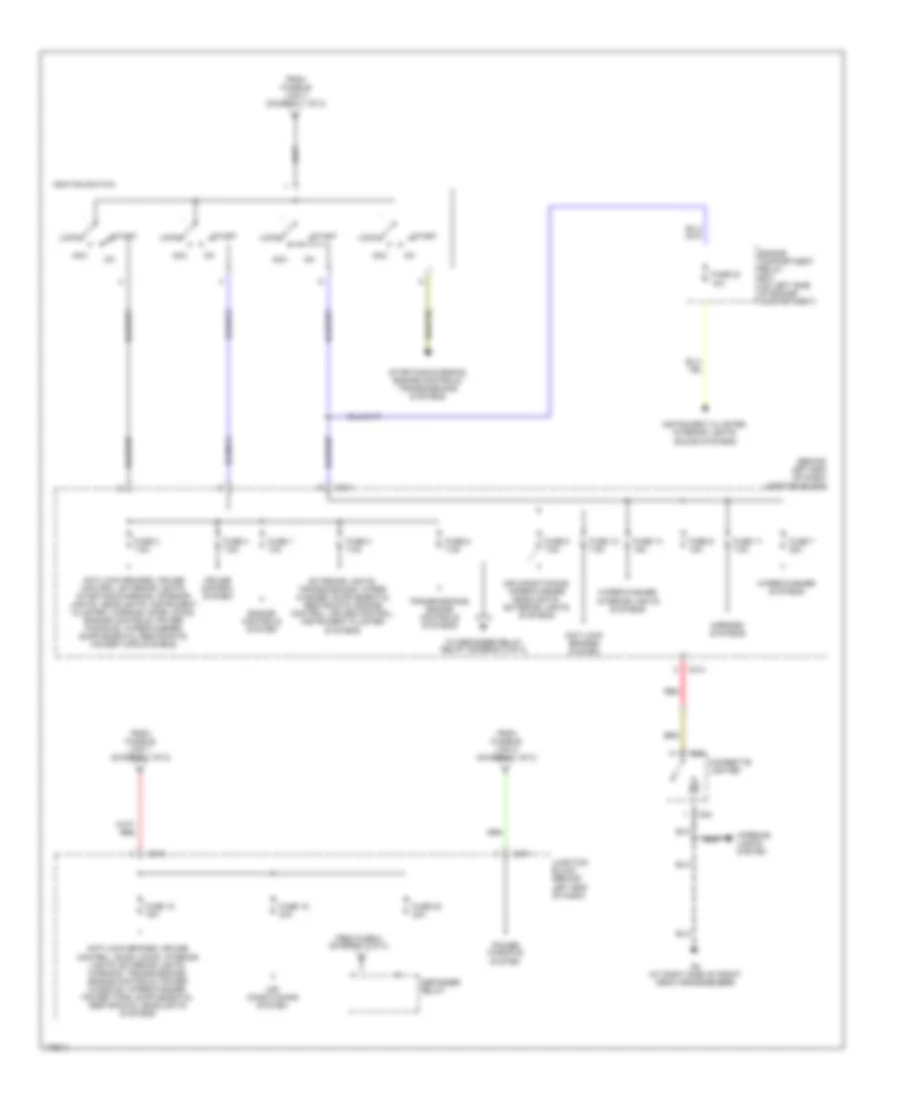
POWER DISTRIBUTION Power Distribution Wiring Diagram (1 of 2) for Mitsubishi Lancer ES 2003 List of elements for Power Distribution Wiring Diagram (1 of 2) for Mitsubishi Lancer ES 2003: 55 (connected to battery positive terminal) Air conditioning system Air conditioning, cooling fans systems Air conditioning, sound, interior lights, defogger, transmissions, instrument cluster, exterior lights systems Anti-lock brakes system Anti-lock brakes, cruise control, transmissions, exterior lights systems Battery Charging system Door locks, exterior lights systems Engine compartment relay box (on left side of engine compartment) Engine controls system Engine controls, transmissions systems Exterior lights system Exterior lights, instrument cluster, transmissions systems Front ecu Fuse 10 15a Fuse 12 7.5a Fuse 13 10a Fuse 14 20a Fuse 15 15a Fuse 16 10a Fuse 17 10a Fuse 18 10a Fuse 19 10a Fuse 20 7.5a Fuse 21 7.5a Fuse 22 10a Fuse 25 15a Fuse 7 10a Fuse 8 20a Fuse 9 10a Fusible link 1 60a Fusible link 2 50a Fusible link 26 100a Fusible link 3 60a Fusible link 4 40a Fusible link 5 30a G10 (w/o turbo) (at rear of cylinder head) (w/ turbo) (at lower left rear of engine) G12 (at left front of engine compt, left of battery) Headlight relay high Headlight relay low Headlights system Headlights system (canada) Horns systems Off Pnk Red Sound, door locks, interior lights, instrument cluster, headlights, warning, power windows, wiper/washer, exterior lights systems Starting system Starting/ charging system Taillight relay To fuse 15 (diagram 2 of 2) To ignition switch (diagram 2 of 2) To junction block (diagram 2 of 2) Transmissions system Power Distribution Wiring Diagram (2 of 2) for Mitsubishi Lancer ES 2003 List of elements for Power Distribution Wiring Diagram (2 of 2) for Mitsubishi Lancer ES 2003: 49 (behind left end of dash) junction block Acc Air conditioning system Air conditioning, wiper/washer headlights, exterior lights systems Anti-lock brakes system C211 C212 C214 Cigarette lighter Cruise control system D23 D24 Defogger relay Engine compartment relay box (on left side of engine compartment) Engine controls system From fuse 5 (diagram 2 of 2) From fusible link 1 (diagram 1 of 2) From fusible link 4 (diagram 1 of 2) From fusible link 5 (diagram 1 of 2) Fuse 1 10a Fuse 11 7.5a Fuse 12 7.5a Fuse 14 15a Fuse 15 15a Fuse 19 30a Fuse 2 7.5a Fuse 20 30a Fuse 23 10a Fuse 3 7.5a Fuse 4 7.5a Fuse 5 7.5a Fuse 7 20a Fuse 8 7.5a Fuse 9 15a G3 (at right side of front deck crossmember) Ignition switch Instrument cluster, interior lights, sound systems Interior lights system Junction block (behind left end of dash) Lock Mirrors systems Power windows system Red Start Starting/charging, engine controls, transmissions systems To defogger relay relay (diagram 2 of 2) Transmissions, engine controls systems Wiper/washer systems Wiper/washer, interior lights systems
POWER DOOR LOCKS Power Door Locks Wiring Diagram, with Keyless Entry for Mitsubishi Lancer ES 2003 List of elements for Power Door Locks Wiring Diagram, with Keyless Entry for Mitsubishi Lancer ES 2003: 46 (at right side of front deck crossmember) g3 C210 C214 C217 C218 C226 C227 C228 Dedicated fuse 22 10a Door lock switch Engine compartment relay box (on left side of engine compt) Etacs ecu Evolution Except evolution Exterior lights system G3 (at right side of front deck crossmember) G6 (behind center of dash, near left center reinforcement) Horns system Hot at all times Hot in start or run Interior lights system Joint connector 1 (behind center of dash) Joint connector 2 (behind instrument cluster) Joint connector 3 (behind right side of dash) Junction block (behind left end of dash) Key reminder switch Left door lock key cylinder switch Left front door lock actuator Left front door switch Left rear door lock actuator Left rear door switch Lock Multi- purpose fuse 15 15a Multi- purpose fuse 2 7.5a Nca Pnk Power window main switch Power window sub switch Red Right door lock key cylinder switch Right front door lock actuator Right front door switch Right rear door lock actuator Right rear door switch Unlock W/ evolution Power Door Locks Wiring Diagram, without Keyless Entry for Mitsubishi Lancer ES 2003 List of elements for Power Door Locks Wiring Diagram, without Keyless Entry for Mitsubishi Lancer ES 2003: 34 C210 C214 C217 C226 C227 C228 Dedicated fuse 22 10a Door lock switch Engine compartment relay box (on left side of engine compt) Etacs ecu G3 (at right side of front deck crossmember) G3 (at right side of front deck crossmember) Hot at all times Hot in start or run Joint connector 1 (behind center of dash) Joint connector 3 (behind right side of dash) Junction block (behind left end of dash) Left door lock key cylinder switch Left front door lock actuator Left front door switch Left rear door lock actuator Lock Multi- purpose fuse 15 15a Multi- purpose fuse 2 7.5a Nca Pnk Power window main switch Power window sub switch Red Right door lock key cylinder switch Right front door lock actuator Right front door switch Right rear door lock actuator Unlock
POWER MIRRORS Power Mirrors Wiring Diagram, Evolution for Mitsubishi Lancer ES 2003 List of elements for Power Mirrors Wiring Diagram, Evolution for Mitsubishi Lancer ES 2003: 14 C214 Down G3 (at right side of front deck crossmember) Hot in acc or run Joint connector 2 (behind right side of dash) Junction block (behind left end of dash) Left Left remote controlled mirror Multi- purpose fuse 11 7.5a Off Red Remote controlled mirror switch Right Right remote controlled mirror Power Mirrors Wiring Diagram, Except Evolution for Mitsubishi Lancer ES 2003 List of elements for Power Mirrors Wiring Diagram, Except Evolution for Mitsubishi Lancer ES 2003: 23 (at right side of front deck crossmember) g3 C214 Defogger system Down E03 E10 E19 E20 G3 (at right side of front deck crossmember) Hot in acc or run Htr Joint connector 3 (behind right side of dash) Junction block (behind left end of dash) Left Left remote controlled mirror Multi- purpose fuse 11 7.5a Off Red Remote controlled mirror switch Right Right remote controlled mirror W/ door mirror heater W/o door mirror heater
POWER TOP/SUNROOF Power Top/Sunroof Wiring Diagram for Mitsubishi Lancer ES 2003 List of elements for Power Top/Sunroof Wiring Diagram for Mitsubishi Lancer ES 2003: 33 (behind instrument cluster) joint connector 2 (evolution) (except evolution) C210 C214 C218 C226 C228 Close/ down Control circuit Dedicated fuse 21 20a Engine compartment relay box (on left side of engine compartment) Etacs ecu Evolution Except evolution G3 (at right side of front deck crossmember) G6 (behind center of dash) G8 g17 (evolution) (except evolution) (at right upper corner of rear shelf panel) Headlights system Hot at all times Hot in on Hot in on or start Joint connector 1 (behind center of dash) Joint connector 3 (behind right side of dash) Junction block (under left end of dash) Multi- purpose fuse 12 7.5a Multi- purpose fuse 2 7.5a Multi- purpose fuse 22 10a Off Open Red Sun roof motor assembly (at rear of sun roof) Sun roof switch
POWER WINDOWS Power Windows Wiring Diagram, Evolution for Mitsubishi Lancer ES 2003 List of elements for Power Windows Wiring Diagram, Evolution for Mitsubishi Lancer ES 2003: 43 C210 C211 C214 C217 C226 C228 Data link connector (below left side of dash) Down Engine compartment relay box (on left side of engine compt) Etacs ecu Fuse 22 10a Fusible link 5 30a G3 (at right side of front deck crossmember) G6 (behind center of dash, near left center reinforcement) Hot at all times Hot in run or start Illum Joint connector (behind right side of dash) Joint connector 1 (behind center of dash) Joint connector 4 Junction block (behind left end of dash) Left front door switch Left front power window switch Left front power window regulator motor Left rear power window switch Left rear power window regulator motor Left rear power window sub switch Lock Lock switch Multi- purpose fuse 2 7.5a Nca Off Power window main switch Power window relay Red Right front door switch Right front power window switch Right front power window regulator motor Right front power window sub switch Right rear power window switch Right rear power window regulator motor Right rear power window sub switch Unlock Power Windows Wiring Diagram, Except Evolution for Mitsubishi Lancer ES 2003 List of elements for Power Windows Wiring Diagram, Except Evolution for Mitsubishi Lancer ES 2003: 42 C210 C211 C214 C217 C226 C228 Data link connector (below left side of dash) Down Engine compartment relay box (on left side of engine compt) Etacs ecu Fuse 10a Fusible link 5 30a G3 (at right side of front deck crossmember) Hot at all times Hot in run or start Illum Joint connector (behind center of dash) Joint connector (behind right side of dash) Joint connector 2 (behind instrument cluster) Junction block (behind left end of dash) Left front door switch Left front power window switch Left front power window motor Left rear power window switch Left rear power window motor Left rear power window switch Lock Lock switch Multi- purpose fuse 2 7.5a Nca Off Power window main switch Power window relay Red Right front door switch Right front power window switch Right front power window motor Right front power window sub switch Right rear power window switch Right rear power window motor Right rear power window switch Unlock
RADIO 4-Speaker System Wiring Diagram for Mitsubishi Lancer ES 2003 List of elements for 4-Speaker System Wiring Diagram for Mitsubishi Lancer ES 2003: 25 (if equipped) pole antenna Antenna amplifier (if equipped) Antenna feeder Antenna feeder cable Cable nca Cd auto changer Dedicated fuse 20 7.5a Dedicated fuse 22 10a Dedicated fuse 23 10a Din cable Engine compartment relay box (on left side of engine compartment) Hot at all times Hot in on or acc Hot w/ taillight relay energized Interior lights system Joint connector 1 (behind center of dash) Joint connector 2 (behind instrument cluster) Left door speaker Left rear speaker Nca Radio & cd player Red Right door speaker Right rear speaker Roof antenna 6-Speaker System Wiring Diagram, Evolution for Mitsubishi Lancer ES 2003 List of elements for 6-Speaker System Wiring Diagram, Evolution for Mitsubishi Lancer ES 2003: 24 Antenna amplifier Antenna feeder cable Cd auto changer Dedicated fuse 20 7.5a Dedicated fuse 22 10a Dedicated fuse 23 10a Din cable Engine compartment relay box (on left side of engine compartment) Hot at all times Hot in on or acc Hot w/ taillight relay energized Interior lights system Joint connector 1 (behind center of dash) Left front door speaker Left rear door speaker Left tweeter Nca Pnk Radio & cd player Red Right front door speaker Right rear door speaker Right tweeter Roof antenna 6-Speaker System Wiring Diagram, Except Evolution for Mitsubishi Lancer ES 2003 List of elements for 6-Speaker System Wiring Diagram, Except Evolution for Mitsubishi Lancer ES 2003: 27 (behind instrument cluster) joint connector 5 (if equipped) pole antenna Antenna amplifier (if equipped) Antenna feeder cable Cable antenna feeder nca Cd auto changer Dedicated fuse 20 7.5a Dedicated fuse 22 10a Dedicated fuse 23 10a Din cable Engine compartment relay box (on left side of engine compartment) Hot at all times Hot in on or acc Hot w/ taillight relay energized Interior lights system Joint connector 1 (behind center of dash) Joint connector 2 (behind instrument cluster) Left door speaker Left rear speaker Left tweeter Nca Radio & cd player Red Right door speaker Right rear speaker Right tweeter Roof antenna
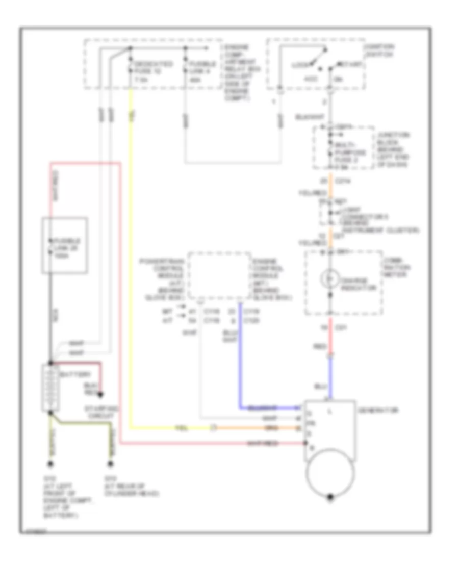
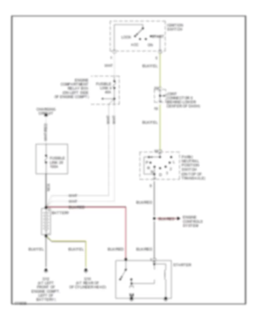
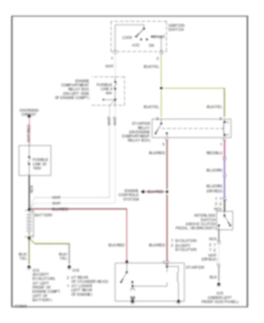
STARTING/CHARGING Charging Wiring Diagram, Evolution for Mitsubishi Lancer ES 2003 List of elements for Charging Wiring Diagram, Evolution for Mitsubishi Lancer ES 2003: 27 40a 7.5a Acc Battery C01 C119 C211 C214 C23 Charge indicator Comb- ination meter Dedicated fuse 12 Engine comp- artment relay box (on left side of engine compt) Engine control module (behind glove box) Fuse 2 7.5a Fusible link 26 100a Fusible link 4 G10 (at lower left rear of engine) Generator Ignition switch Joint connector 4 Junction block (behind left end of dash) Lock Nca Red Start Starting circuit Charging Wiring Diagram, Except Evolution for Mitsubishi Lancer ES 2003 List of elements for Charging Wiring Diagram, Except Evolution for Mitsubishi Lancer ES 2003: 33 40a 7.5a A/t Acc Battery C01 C118 C119 C120 C21 C211 C214 Charge indicator Comb- ination meter Dedicated fuse 12 Engine comp- artment relay box (on left side of engine compt) Engine control module (m/t) (behind glove box) Fusible link 26 100a Fusible link 4 G10 (at rear of cylinder head) G12 (at left front of engine compt, left of battery) Generator Ignition switch Joint connector 5 (behind instrument cluster) Junction block (behind left end of dash) Lock M/t Multi- purpose fuse 2 7.5a Nca Powertrain control module (a/t) (behind glove box) Red Start Starting circuit Starting Wiring Diagram, A/T for Mitsubishi Lancer ES 2003 List of elements for Starting Wiring Diagram, A/T for Mitsubishi Lancer ES 2003: 17 (on top of transaxle) Acc Battery Charging circuit Engine compartment relay box (on left side of engine compt) Engine controls system Fusible link 26 100a Fusible link 4 40a G10 (at rear of of cylinder head) G12 (at left front of engine compt, left of battery) Ignition switch Joint connector 6 (behind lower center of dash) Lock Nca Park/ neutral position switch Start Starter Starting Wiring Diagram, M/T for Mitsubishi Lancer ES 2003 List of elements for Starting Wiring Diagram, M/T for Mitsubishi Lancer ES 2003: 24 (at left front of engine compt, left of battery) (or red) Acc At rear Battery Charging circuit Engine compartment relay box (on left side of engine compt) Engine controls system Evolution Except evolution Fusible link 26 100a Fusible link 4 40a G10 G12 (except evolution) G15 (under left front kick panel) Ignition switch Interlock switch (above clutch pedal, on bracket) Left rear of engine) Lock Nca Of cylinder head) (at lower Start Starter Starter relay (on engine compartment relay box)
SUPPLEMENTAL RESTRAINTS Supplemental Restraints Wiring Diagram, Evolution (1 of 2) for Mitsubishi Lancer ES 2003 List of elements for Supplemental Restraints Wiring Diagram, Evolution (1 of 2) for Mitsubishi Lancer ES 2003: 30 (at left front of engine compartment) left front impact sensor (at right front of engine compartment) right front impact sensor (at top left side of dash) g7 (behind center of dash, on right dash support) g16 (partial) (below left side of Air bag drive circuit C-01 C-02 C-12 C-214 Clock spring Combination meter Connector lock switch (connector coupled: on) (connector uncoupled: off) Dash) Data Data link connector (dlc) Detection circuit Driver's side air bag module (squib) (in steering column) Fuse 7.5a Ground Hot in on or start Ignition J/c 2 (behind instrument cluster) J/c 4 Junction block (behind left end of dash) Nca Off Srs ecu (behind lower center of dash) Srs indicator Warning light Supplemental Restraints Wiring Diagram, Evolution (2 of 2) for Mitsubishi Lancer ES 2003 List of elements for Supplemental Restraints Wiring Diagram, Evolution (2 of 2) for Mitsubishi Lancer ES 2003: 11 (at base of right "b" pillar, behind trim) right seat belt pretensioner (at right side of dash) passenger's side air bag module squib (connector coupled: on) (connector uncoupled: off) connector lock switch Air bag drive circuit C-13 Connector lock switch (connector coupled: on) (connector uncoupled: off) Left seat belt pretensioner (at base of left "b" pillar, behind trim) Nca Off Red Srs ecu (behind lower center of dash) Supplemental Restraints Wiring Diagram, Except Evolution (1 of 2) for Mitsubishi Lancer ES 2003 List of elements for Supplemental Restraints Wiring Diagram, Except Evolution (1 of 2) for Mitsubishi Lancer ES 2003: 22 (at top left side of dash) g7 (behind center of dash, on right dash support) g16 (partial) (below left side of Air bag drive circuit C-12 Clock spring Connector lock switch (connector coupled: on) (connector uncoupled: off) Connector lock switch (connector coupled: on) connector uncoupled: off) Dash) Data Data link connector (dlc) Detection circuit Driver's side air bag module squib Ground Ignition J/c 2 (behind combination meter) Nca Off Passenger's side air bag module squib Right side air bag squib module (w/side air bag) Srs ecu (behind lower center of dash) Warning light Supplemental Restraints Wiring Diagram, Except Evolution (2 of 2) for Mitsubishi Lancer ES 2003 List of elements for Supplemental Restraints Wiring Diagram, Except Evolution (2 of 2) for Mitsubishi Lancer ES 2003: 24 Air bag drive circuit C-01 C-02 C-13 C-214 Combination meter Connector lock switch (connector coupled: on) (connector uncoupled: off) Fuse 7.5a Hot in on or start Interface J/c 5 (behind combination meter) Junction block (behind left end of dash) Left seat belt pretensioner (at base of left "b" pillar, behind trim) Left side air bag module squib (w/side air bags) Left side impact sensor (w/side air bags) (at base of left "b" pillar, behind trim) Nca Off Pnk Red Right seat belt pretensioner (at base of right "b" pillar, behind trim) Right side impact sensor (w/side air bags) (at base of right "b" pillar, behind trim) Solid state Srs ecu (behind lower center of dash) Srs indicator
TRANSMISSION A/T Wiring Diagram for Mitsubishi Lancer ES 2003 List of elements for A/T Wiring Diagram for Mitsubishi Lancer ES 2003: 38 (behind left side of dash) g14 A/t control relay (on engine compt relay box) A/t control solenoid valve assembly (rear of transaxle) A/t oil temp C-114 C-116 C-118 C-120 C-210 Crankshaft position sensor (on lower front of engine) Data link connector (below left side of dash) Engine compartment relay box (left side of engine compt) Engine controls system Engine coolant temperature sensor (rear of cyl head) Exterior lights system Fuse 15a Fuse 20a Fuse 7.5a Hot at all times Hot in run or start Input shaft speed sensor (top of transaxle) J/c 2 (behind left side of dash) J/c 6 (behind left side of dash) J/c 6 (below center of dash) Junction block (behind left end of dash) Low/ reverse Mfi relay (on engine compartment relay box) Output shaft speed sensor (top of transaxle) Over drive Park/neutral position switch (top of transaxle) Powertrain control module (behind glove box) Red Second Starting/ charging system Stop light switch (above brake pedal) Throttle position sensor (on throttle body) Torque converter control Under drive
WARNING SYSTEMS Warning Systems Wiring Diagram, Evolution for Mitsubishi Lancer ES 2003 List of elements for Warning Systems Wiring Diagram, Evolution for Mitsubishi Lancer ES 2003: 33 (at right side of front deck crossmember) g3 (behind instrument cluster) joint connector 2 C01 C02 C210 C214 C217 C226 C227 C228 Column ecu Column switch Combination meter Computer data lines system Door ind Engine compartment relay box (on left side of engine compt) Etacs-ecu Fuse 10a G6 (behind center of dash, near left center reinforcement) Hot at all times Hot in run or start Joint connector 1 (behind center of dash) Joint connector 2 (behind instrument cluster) Joint connector 3 (behind right side of dash) Joint connector 4 Junction block (behind left end of dash) Key reminder switch Left front door switch Multi- purpose fuse 2 7.5a Nca Red Seat belt ind Seat belt switch (inside driver's seat belt buckle) Warning Systems Wiring Diagram, Except Evolution for Mitsubishi Lancer ES 2003 List of elements for Warning Systems Wiring Diagram, Except Evolution for Mitsubishi Lancer ES 2003: 31 (at right side of front deck crossmember) g3 (behind instrument cluster) joint connector 5 C01 C02 C210 C214 C217 C226 C227 C228 Column ecu Column switch Combination meter Computer data lines system Door ind Engine compartment relay box (on left side of engine compt) Etacs-ecu Fuse 10a Hot at all times Hot in run or start Joint connector 1 (behind center of dash) Joint connector 3 (behind right side of dash) Joint connector 4 Junction block (behind left end of dash) Key reminder switch Left front door switch Multi- purpose fuse 2 7.5a Nca Red Seat belt ind Seat belt switch (inside driver's seat belt buckle)
WIPER/WASHER Front Wiper/Washer Wiring Diagram, Evolution for Mitsubishi Lancer ES 2003 List of elements for Front Wiper/Washer Wiring Diagram, Evolution for Mitsubishi Lancer ES 2003: 50 A10x A11x Acc or on Air conditioning system C210 C214 C226 C228 Circuit breaker Column ecu Column switch Dedicated fuse 22 10a Engine compartment relay box (on left side of engine compartment) Engine controls systems Etacs ecu Fast Front ecu (in engine compartment relay box) G13 (at left front corner of engine compartment) G14 (under front of center console) G3 (at right side of front deck crossmember) G6 (behind center of dash, near left center reinforcement) G8 (under rear seat back, at right upper corner of rear shelf panel) High Hot at all times Hot in Hot in on Hot in start Int Intermittent wiper interval adjusting knob Joint connector 1 (behind center of dash) Joint connector 2 (behind instrument cluster) Joint connector 3 (behind right side of dash) Joint connector 4 Joint connector 5 (behind instrument cluster) Junction block (behind left end of dash) Low Mist Multi- purpose fuse 2 7.5a Multi- purpose fuse 5 7.5a Multi- purpose fuse 7 20a Or on Pnk Red Slow Vehicle speed sensor (on right side of transaxle) Wash Washer switch Windshield washer motor (at right rear of trunk, on washer fluid reservoir) Windshield wiper motor (on right rear of engine compt) Wiper switch Front Wiper/Washer Wiring Diagram, Except Evolution for Mitsubishi Lancer ES 2003 List of elements for Front Wiper/Washer Wiring Diagram, Except Evolution for Mitsubishi Lancer ES 2003: 52 (at right rear of trunk, on washer fluid reservoir) A/t A10x A11x Acc or on C116 C210 C214 C226 C228 Circuit breaker Column ecu Column switch Cruise control, engine controls systems Dedicated fuse 22 10a Engine compartment relay box (on left side of engine compartment) Etacs ecu Fast Front ecu (in engine compartment relay box) G1 (at right front corner of engine compartment) G13 (at left front corner of engine compartment) G14 (under front of center console) G3 (at right side of front deck crossmember) High Hot at all times Hot in Hot in on Hot in start Int Intermittent wiper interval adjusting knob Joint connector 1 (behind center of dash) Joint connector 2 (behind instrument cluster) Joint connector 3 (behind right side of dash) Joint connector 5 (behind instrument cluster) Junction block (behind left end of dash) Low M/t Mist Multi- purpose fuse 2 7.5a Multi- purpose fuse 5 7.5a Multi- purpose fuse 7 20a Off Or on Pnk Powertrain control module (behind glove box) Slow Vehicle speed sensor (on right side of transaxle) Wash Washer switch Windshield washer motor Windshield wiper motor (on right rear of engine compt) Wiper switch Rear Wiper/Washer Wiring Diagram, Evolution for Mitsubishi Lancer ES 2003 List of elements for Rear Wiper/Washer Wiring Diagram, Evolution for Mitsubishi Lancer ES 2003: 39 (behind center of dash, near left center reinforcement) g6 (behind instrument cluster) joint (below left side of dash) (under rear seat back, at left upper corner of rear shelf panel) Acc or on Back-up light switch (on top of transaxle) C210 C214 C217 C226 C227 C228 Column ecu Column switch Connector 2 Connector 3 (behind right side of dash) Data link connector Dedicated fuse 22 10a Engine compartment relay box (on left side of engine compartment) Etacs ecu G3 (at right side of front deck crossmember) G8 (under rear seat back, at right upper corner of rear shelf panel) Hot at all times Hot in Joint Joint connector 1 (behind center of dash) Joint connector 4 Junction block (behind left end of dash) Multi- purpose fuse 14 15a Multi- purpose fuse 2 7.5a Multi- purpose fuse 3 7.5a Nca Pnk Rear washer motor (at right rear of trunk, on washer fluid reservoir) Rear washer switch Rear wiper motor (below right side of rear speaker shelf) Rear wiper switch Red Start or on Rear Wiper/Washer Wiring Diagram, Except Evolution for Mitsubishi Lancer ES 2003 List of elements for Rear Wiper/Washer Wiring Diagram, Except Evolution for Mitsubishi Lancer ES 2003: 38 (at right side of front deck crossmember) g3 A/t Acc or on Back-up light switch (on top of transaxle) C210 C214 C217 C226 C227 C228 Column ecu Column switch Dedicated fuse 22 10a Engine compartment relay box (on left side of engine compartment) Etacs ecu G1 (at right front corner of engine compartment) G9 (under rear seat back, at left upper corner of rear shelf panel) Hot at all times Hot in Joint connector 1 (behind center of dash) Joint connector 2 (behind instrument cluster) Joint connector 3 (behind right side of dash) Joint connector 5 (behind instrument cluster) Junction block (behind left end of dash) M/t Multi- purpose fuse 14 15a Multi- purpose fuse 2 7.5a Multi- purpose fuse 3 7.5a Nca Off Park/neutral position switch (on top of transaxle) Pnk Rear washer motor (at right rear of trunk, on washer fluid reservoir) Rear washer switch Rear wiper motor (below right side of rear speaker shelf) Rear wiper switch Red Start or on