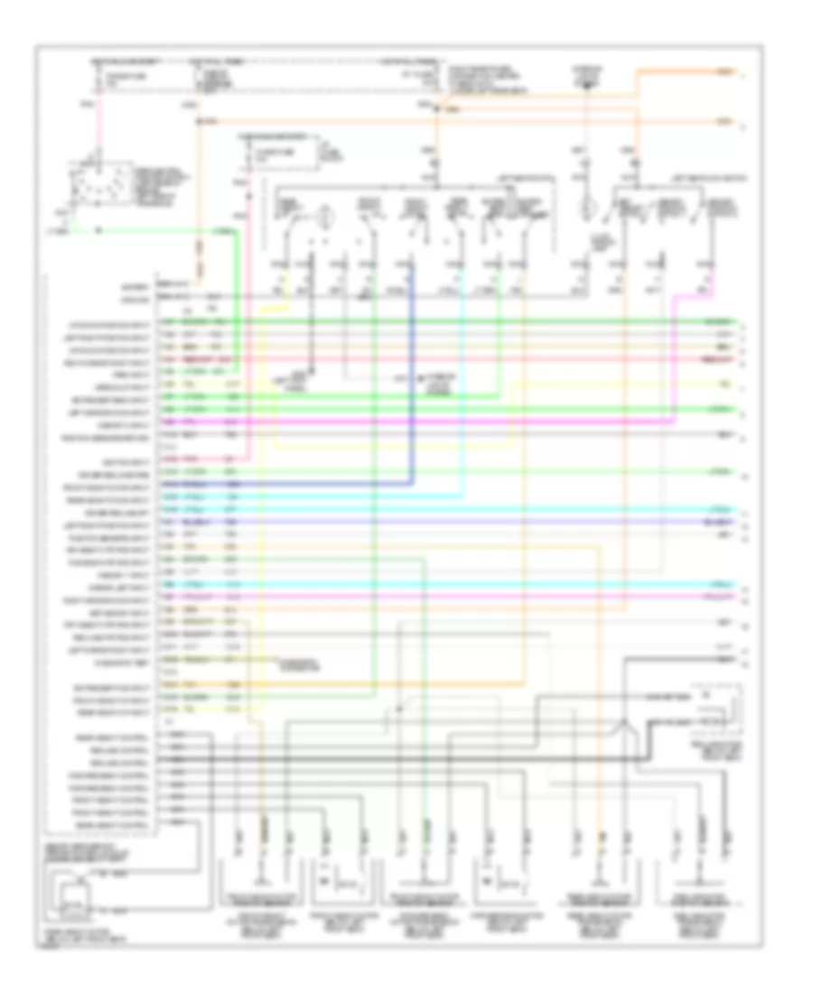
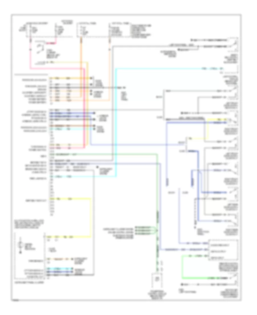
AIR CONDITIONING
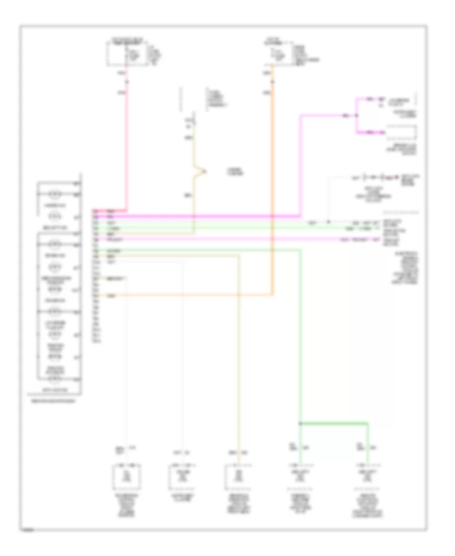
Air Conditioning Wiring Diagrams (1 of 2) for Oldsmobile Aurora 1996

List of elements for Air Conditioning Wiring Diagrams (1 of 2) for Oldsmobile Aurora 1996:
- (left front
- (right front shroud)
- +5v
- A/c high pressure cut-out switch (on rear of compressor)
- A/c low pressure switch (right front engine compartment)
- A/c req
- A10
- A11
- A12
- Act enable
- Act sense
- Amb temp input
- Ambient temperature sensor (center front of vehicle)
- B10
- B11
- B12
- Battery
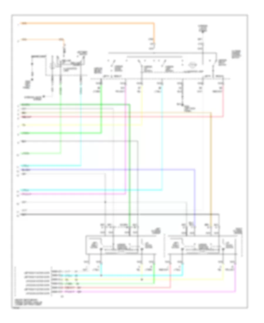
- Blower control module (behind right side of i/p)
- Blower ctrl
- Blower motor
- Blw speed feedbk
- Blw speed input
- C 1995 vftc
- C10
- C11
- C12
- C13
- C14
- C15
- C16
- Computer data lines
- D10
- D11
- D12
- D13
- D14
- D15
- D16
- Data line
- Defog rly ctrl
- Driver information center
- G119 (right front of engine)
- G200
- G203
- G203 (right front shroud)
- Ground
- Heater and a/c control assembly
- Hot at all times
- Hot at all times rear maxi fuse block
- Hvac blo mot fuse 30a
- Hvac blower 10a
- Hvac programmer (behind right side of i/p)
- I/p 1 fuse 15a
- I/p fuse block
- Ignition
- Illumination
- In-vehicle temperature sensor (behind center of i/p)
- Inside temp input
- Interior ligths system
- Left solar sensor (top left of i/p)
- Lt solar sensor
- Pass ctrl gnd
- Pass ctrl input
- Passenger climate control assembly
- Passenger heated seat module
- Pwm blw spd ctrl
- Rear defogger system
- Red
- Right rear power distri- bution center fuse block 1
- Right solar sensor (top right of i/p)
- Rt solar sensor
- Sensor ground
- Shroud)
- Signal status
- Tan
- Uart
Air Conditioning Wiring Diagrams (2 of 2) for Oldsmobile Aurora 1996
List of elements for Air Conditioning Wiring Diagrams (2 of 2) for Oldsmobile Aurora 1996:
- (behind i/p, on plenum)
- A/c compressor clutch
- A/c compressor clutch diode
- A/c compressor clutch relay (in engine compartment 2 relay center)
- A/c high temperature sensor (right front of engine compartment)
- A/c low temperature sensor (under wiper motor)
- A/c mode actuator (behind i/p, on plenum)
- A/c request
- Air inlet actuator (behind i/p, on plenum)
- C 1995 vftc
- Clng fan fuse 10a
- Cooling fan fuse 60a
- Cooling fan relay 1 (rear center of engine compartment)
- Cooling fan relay 2 (in right front under- hood relay center)
- Cooling fan relay 3 (in right front under- hood relay center)
- Cr cont fuse 10a
- Driver's side actuator (behind i/p, on plenum)
- Engine coolant temperature sensor (top left side of
- Engine)
- G103 (right front strut tower)
- Heater/defroster actuator (behind i/p, on plenum)
- Hot at all
- Hot in run
- I/p fuse block
- Ign 3 fuse 10a
- Left cooling fan
- Left cooling fan diode
- Nca
- Or start
- Passenger's side actuator
- Pnk
- Powertrain control module (behind right side of i/p, near shroud)
- Red
- Relay control
- Right cooling fan
- Right front underhood relay center
- Sensor ground
- Sensor input
- Solid state
- Switch input
- Times
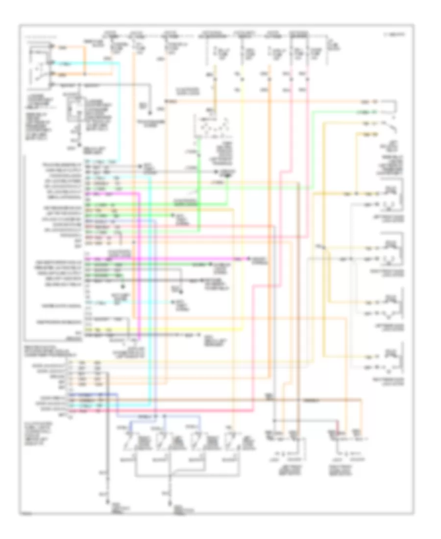
ANTI-LOCK BRAKES
Anti-lock Brake Wiring Diagrams for Oldsmobile Aurora 1996
List of elements for Anti-lock Brake Wiring Diagrams for Oldsmobile Aurora 1996:
- (buick) (olds)
- (left front lower frame rail)
- (left side
- (right i/p, near shroud) powertrain control module
- 1141 or 441
- A red
- Abs
- Abs fuse 10a
- Abs ind request
- Abs main relay (center rear of engine compt)
- Abs pump motor fuse 40a
- Abs pump motor relay (center rear of engine compt)
- Anti- lock ind
- Antilock diode (right of steering column)
- Bat
- Chime fuse 10a
- Computer data lines
- Cruise/shift interlock/ brake switch (on brake pedal support)
- Desired torque in
- Desired torque out
- Electronic brake (& traction) control module (attached to left front strut tower)
- Fluid level input
- Fluid level switch
- G100
- G100 (left front lower frame rail)
- G200 (left kick panel)
- Grd
- Hot at all times
- Hot in run
- Hot in run or start
- Hzrd/
- I/p fuse block
- Ign
- Ign 1 fuse 10a
- Ign 3
- Interior lights system
- L isolation
- Left front
- Left iso vlv ctrl
- Left rear
- Lf inlet
- Lf inlet vlv ctrl
- Lf outlet
- Lf outlet vlv ctrl
- Lf wss (+)
- Lf wss (-)
- Lr inlet
- Lr inlet vlv ctrl
- Lr outlet
- Lr outlet vlv ctrl
- Lr wss (+)
- Lr wss (-)
- Main fuse 30a
- Main relay ctrl
- Nca
- Of i/p)
- Olds w/traction control
- Pedal travel switch
- Pnk
- Pnk a
- Pressure input
- Pressure modulator valve assembly (lower left front of engine compt)
- Pressure switch
- Program input
- Pump motor
- Pump motor run sensor
- Pump mtr relay ctrl
- Pump mtr sense (hi)
- Pump mtr sense (lo)
- R isolation
- Rear fuse block (below rear seat)
- Red
- Remote indicator bank or instrument cluster
- Rf inlet
- Rf inlet vlv ctrl
- Rf outlet
- Rf outlet vlv ctrl
- Rf wss (+)
- Rf wss (-)
- Right front
- Right front underhood relay center (right front of engine compartment)
- Right iso vlv ctrl
- Right rear
- Rr inlet
- Rr inlet vlv ctrl
- Rr outlet
- Rr outlet vlv ctrl
- Rr wss (+)
- Rr wss (-)
- Stop fuse 20a
- Switch return
- Tan
- Tcc/antilock brake switch (on brake pedal support)
- Tract active ind
- Tract active ind ctrl
- Tract off ind
- Tract off ind ctrl
- Traction control on/off switch
- Traction off input
- Uart data line
- W/ traction control
- W/traction control
- Wheel speed sensor
ANTI-THEFT
Forced Entry Wiring Diagram for Oldsmobile Aurora 1996
List of elements for Forced Entry Wiring Diagram for Oldsmobile Aurora 1996:
- (under rear seat, left side of rocker panel)
- Battery
- Door lock
- Door lock input
- Door open input
- Door unlock
- Door unlock input
- E10
- E11
- E12
- E15
- E16
- F10
- F16
- G203 (right front shroud)
- G312
- G312 (under rear seat, left side of rocker panel)
- Ground
- Headlamps alarm input
- Headlamps output
- Horn rly ctrl
- Horns system (horn relay)
- Hot in run, bulb test or start
- Hto at all times
- I/p 1 fuse 10a
- I/p fuse block
- Ign-1 fuse 10a
- Ignition
- Key unlock input
- Lamp control module (behind left kick panel)
- Left door lock cylinder switch
- Left front door jamb switch
- Left rear door jamb switch (olds only)
- Lf door jamb input
- Lock
- Luggage compartment lid tamper switch
- Luggage compt ajar
- Multi-function alarm, lock and lighting module (left instrument panel)
- Passkey circuit (security indicator)
- Pnk
- Remote function actuation module (right front of luggage compt)
- Right door lock cylinder switch
- Right front door jamb switch (buick) right front door lock actuator (olds)
- Right rear door jamb switch (olds only)
- Right rear electrical center (under rear seat)
- Security indicator
- Tan
- Un- lock
Pass-Key Wiring Diagram for Oldsmobile Aurora 1996
List of elements for Pass-Key Wiring Diagram for Oldsmobile Aurora 1996:
- (buick)
- (olds)
- (right front shroud)
- A16
- A17
- Acc
- Bat
- Bulb test
- Crank fuse 10a
- E14
- Enable out
- G203
- Ground
- Hot at all times
- Hot in run or start
- Hot in start
- I/p 1 fuse 10a
- I/p fuse block
- Ign
- Ignition key
- Ignition key lock cylinder
- Ignition switch
- Ind cntrl
- Key res in
- Lock
- Nca
- Neutral position
- Off
- Olds only
- Park/
- Passkey ii decoder module (behind right side of i/p)
- Pcm fuse 10a
- Pcm/ vats fuse 20a
- Pnk
- Powertrain control module (behind right i/p)
- Red
- Remote function actuation module (right front of luggage compt)
- Remote indicator bank (olds) instrument cluster (buick)
- Resistor pellet
- Right rear electrical center (below rear seat)
- Rly cntrl
- Run
- Security indicator
- Start
- Starter enable relay (lower left of steering column)
- Starter solenoid
- Strtr disable
- Switch
BODY COMPUTER
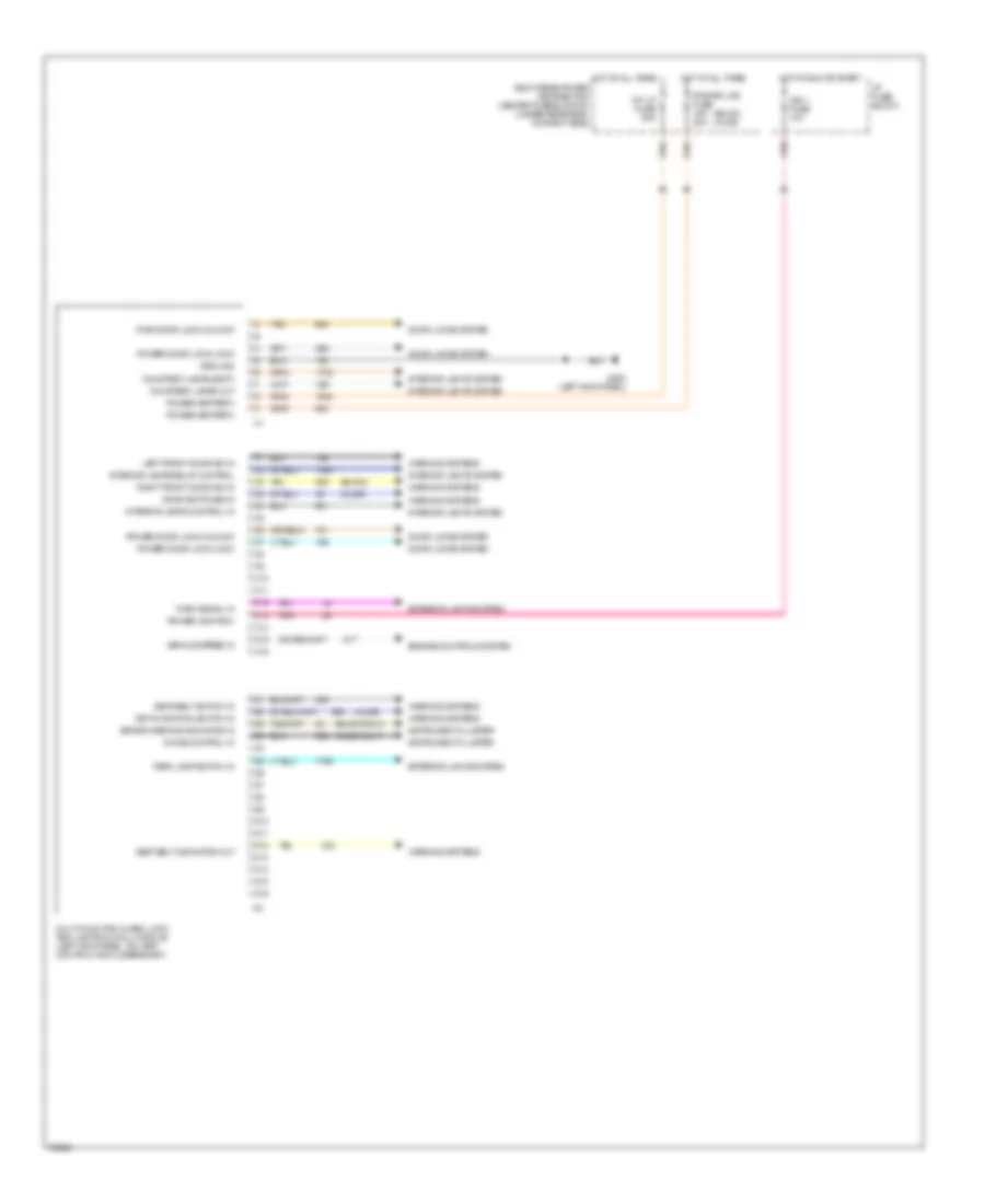
Body Computer Wiring Diagrams for Oldsmobile Aurora 1996
List of elements for Body Computer Wiring Diagrams for Oldsmobile Aurora 1996:
- (buick only)
- (buick)
- (buick) (olds)
- (olds only)
- (olds)
- Brake warning indicator in
- C10
- C11
- C12
- C13
- C14
- C15
- C16
- Chime control in
- Courtesy lamps (batt)
- Courtesy lamps out
- D10
- D11
- D12
- D13
- D14
- D15
- D16
- Door locks system
- Door switches in
- Engine controls system
- Exterior lights system
- G200 (left kick panel)
- Ground
- Hot at all times
- Hot in run or start
- I/p fuse block
- Ign 1 fuse 10a
- Instrument cluster
- Int lp fuse 20a
- Interior lamps control in
- Interior lamps relay control
- Interior lights system
- Key-in-ignition switch in
- Left front door sw in
- Multi-function alarm, lock and lighting (mall) module (left kick panel, on lamp control module bracket)
- Park lamp switch in
- Pnk
- Power (battery)
- Power (ignition)
- Power door lock-lock
- Power door lock-unlock
- Pwr door lock-unlock
- Pwr dr lks fuse 15a 20a
- Right front door sw in
- Right rear power distribution center fuse block #1 (under rear seat, on right side)
- Seat belt indicator out
- Seat belt switch in
- Tan
- Turn signal in
- Vehicle speed in
- Warning systems
COMPUTER DATA LINES
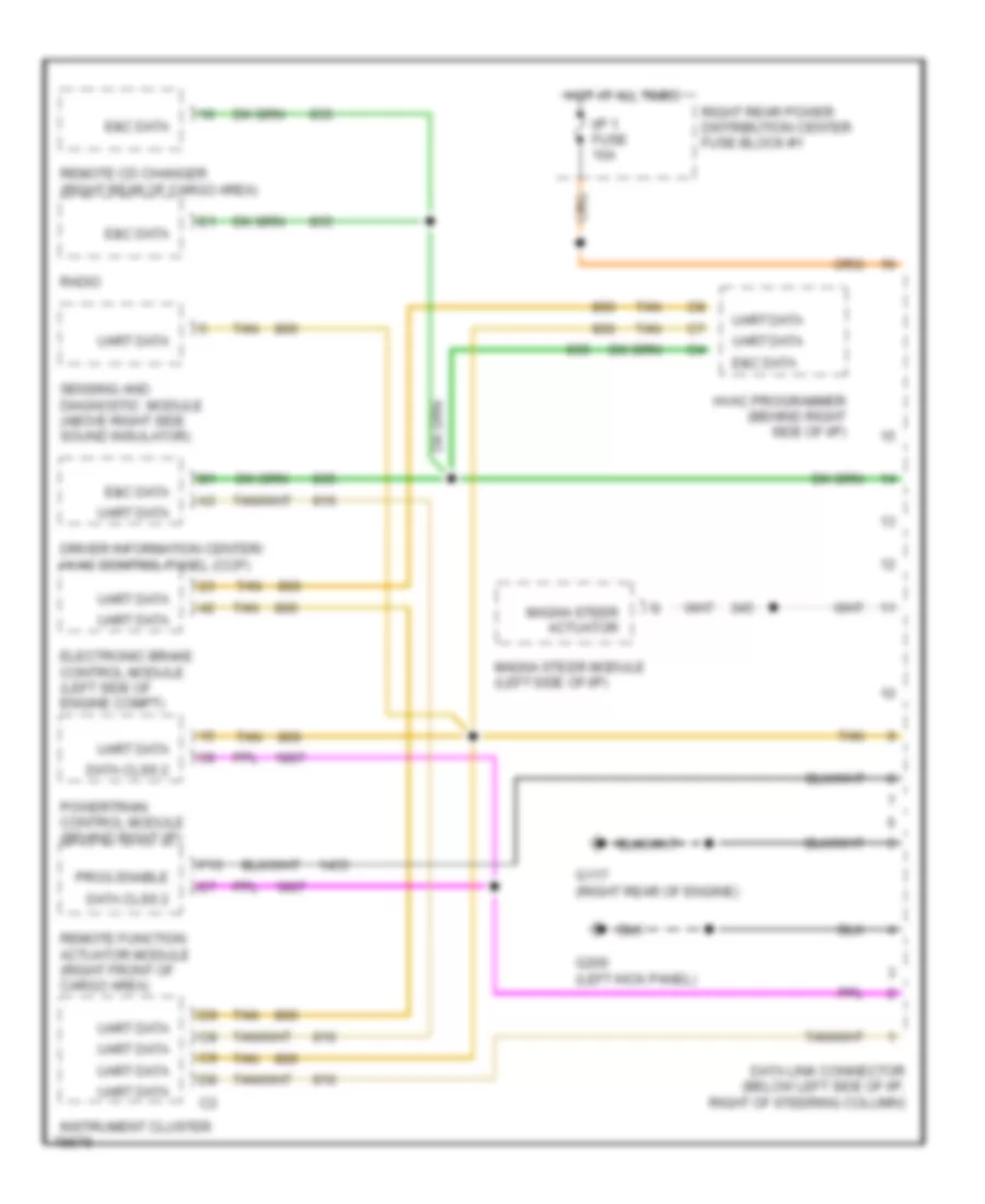
Computer Data Lines for Oldsmobile Aurora 1996
List of elements for Computer Data Lines for Oldsmobile Aurora 1996:
- Data clss 2
- Data link connector (below left side of i/p, right of steering column)
- Driver information center/ hvac control panel (ccp)
- E&c data
- Electronic brake control module (left side of engine compt)
- F13
- G117 (right rear of engine)
- G200 (left kick panel)
- Hot at all times
- Hvac programmer (behind right side of i/p)
- I/p 1 fuse 10a
- Instrument cluster
- Magna steer actuator
- Magna steer module (left side of i/p)
- Powertrain control module (behind right i/p)
- Prog enable
- Radio
- Remote cd changer (right rear of cargo area)
- Remote function actuator module (right front of cargo area)
- Right rear power distribution center fuse block #1
- Sensing and diagnostic module (above right side sound insulator)
- Tan
- Uart data
COOLING FAN
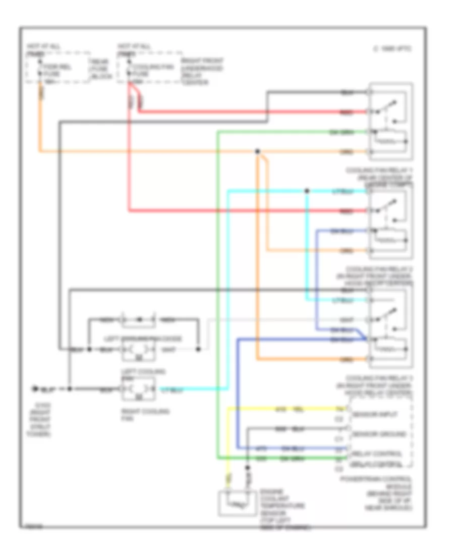
Cooling Fan Wiring Diagram for Oldsmobile Aurora 1996
List of elements for Cooling Fan Wiring Diagram for Oldsmobile Aurora 1996:
- C 1995 vftc
- Cooling fan fuse 60a
- Cooling fan relay 1 (rear center of engine compt)
- Cooling fan relay 2 (in right front under- hood relay center)
- Cooling fan relay 3 (in right front under- hood relay center)
- Engine coolant temperature sensor (top left side of engine)
- F/dr rel fuse 10a
- G103 (right front strut tower)
- Hot at all
- Left cooling fan
- Left cooling fan diode
- Nca
- Powertrain control module (behind right side of i/p, near shroud)
- Rear fuse block
- Red
- Relay control
- Right cooling fan
- Right front underhood relay center
- Sensor ground
- Sensor input
- Times
CRUISE CONTROL
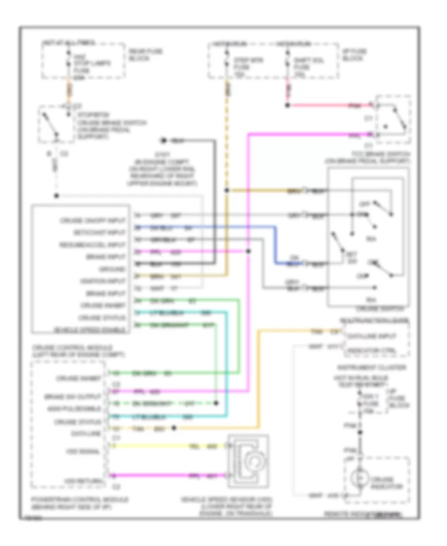
Cruise Control Wiring Diagram for Oldsmobile Aurora 1996
List of elements for Cruise Control Wiring Diagram for Oldsmobile Aurora 1996:
- 4000 pulses/mile
- A10
- A11
- Brake input
- Brake sw output
- C 1995 vftc
- Cruise brake switch (on brake pedal support)
- Cruise control module (left rear of engine compt)
- Cruise indicator
- Cruise inhibit
- Cruise on/off input
- Cruise status
- Cruise switch
- Data line
- Data line input
- G101 (in engine compt, on right lower rail rearward of right upper engine mount)
- Ground
- Haz stop lamps fuse 20a
- Hot at all times
- Hot in run
- Hot in run, bulb test or start
- I/p fuse block
- Ign 1 fuse 10a
- Ignition input
- Indicator ctrl
- Instrument cluster
- Multifunction lever
- Off
- Pnk
- Powertrain control module (behind right side of i/p)
- R/a
- Rear fuse block
- Remote indicator bank
- Resume/accel input
- Set sw
- Set/coast input
- Shift sol fuse 10a
- Step mtr fuse 15a
- Stop/btsi/
- Tan
- Tcc brake switch (on brake pedal support)
- Vehicle speed enable
- Vehicle speed sensor (vss) (lower right rear of engine, on transaxle)
- Vss return
- Vss signal
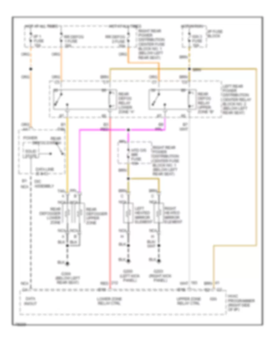
DEFOGGERS
Defogger Wiring Diagram for Oldsmobile Aurora 1996
List of elements for Defogger Wiring Diagram for Oldsmobile Aurora 1996:
- D12
- D13
- Data
- Data line (e & c)
- Dic assembly
- G200 (left kick panel)
- G203 (right kick panel)
- G304 (below left rear seat)
- Hot at all times
- Hot in run
- Htd o/s mir fuse 10a
- Hvac programmer (right side of i/p)
- I/p 1 fuse 10a
- I/p fuse block
- Ign
- Ign 3 fuse 10a
- In/out
- Left heated mirror element
- Left rear power distribution center relay block no. 2 (below left rear seat)
- Lower zone relay ctrl
- Nca
- Power
- Rear defog relay lower zone "a"
- Rear defog relay upper zone "b"
- Rear defog switch
- Rear defogger lower zone
- Rear defogger upper zone
- Red
- Right heated mirror element
- Right rear power distribution center fuse block no. 1 (below left rear seat)
- Rr defog 1 fuse 30a
- Rr defog 2 fuse 30a
- Solid state
- Tan
- Upper zone relay ctrl
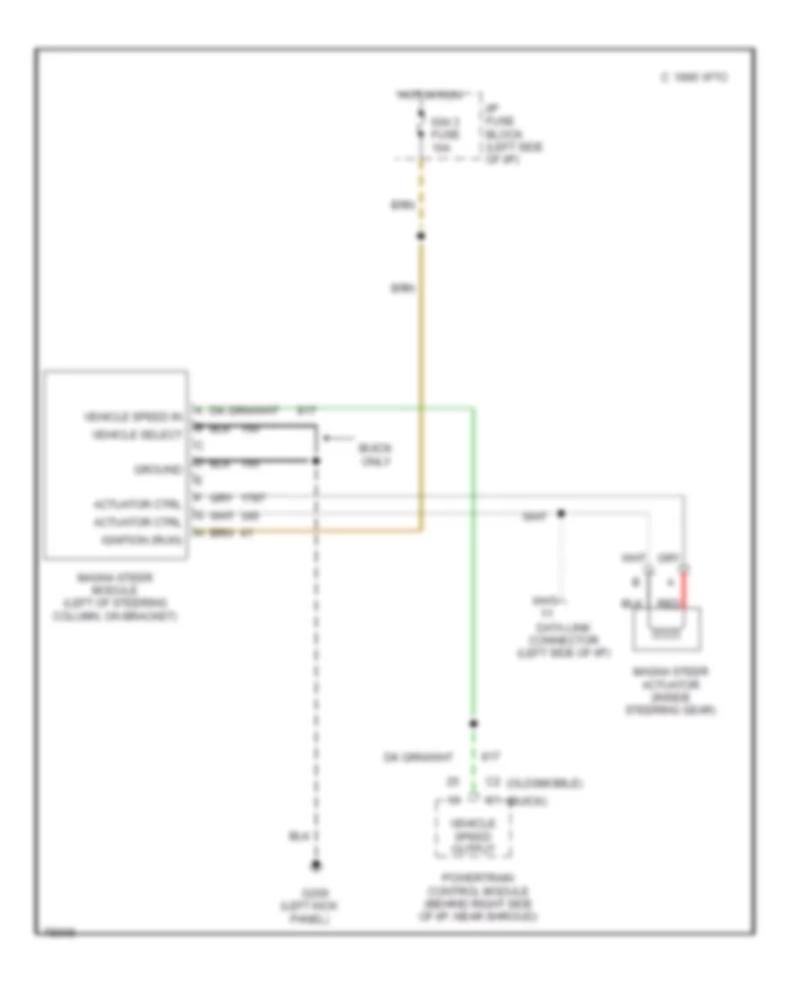
ELECTRONIC POWER STEERING
Electronic Power Steering Wiring Diagram for Oldsmobile Aurora 1996
List of elements for Electronic Power Steering Wiring Diagram for Oldsmobile Aurora 1996:
- (buick)
- (left kick
- (oldsmobile)
- 1995 vftc c
- Actuator ctrl
- Buick only
- Data link connector (left side of i/p)
- G200
- Ground
- Hot in run
- I/p fuse block (left side of i/p)
- Ign 3 fuse 10a
- Ignition (run)
- Magna steer actuator (inside steering gear)
- Magna steer module (left of steering column, on bracket)
- Panel)
- Powertrain control module (behind right side of i/p, near shroud)
- Red
- Vehicle select
- Vehicle speed in
- Vehicle speed output
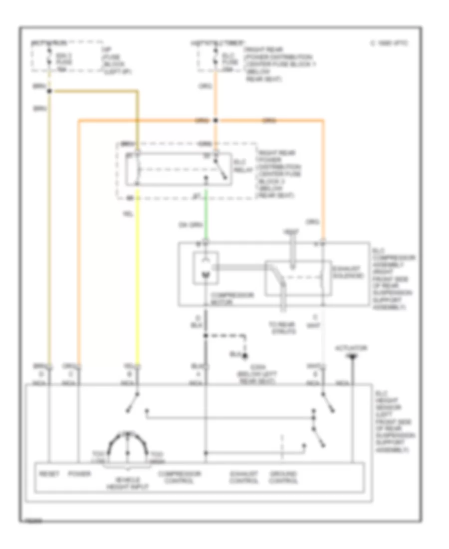
ELECTRONIC SUSPENSION
Electronic Level Control for Oldsmobile Aurora 1996
List of elements for Electronic Level Control for Oldsmobile Aurora 1996:
- (below left rear seat)
- Actuator arm
- C 1995 vftc
- Compressor control
- Compressor motor
- Elc
- Elc compressor assembly (right front side of rear suspension support assembly)
- Elc fuse 20a
- Elc height sensor (left front side of rear suspension support assembly)
- Exhaust control
- Exhaust solenoid
- G304
- Ground control
- Hot at all times
- Hot in run
- I/p fuse block (left i/p)
- Ign 3 fuse 10a
- Level
- Nca
- Power
- Relay
- Reset
- Right rear power distribution center fuse block 1 (below rear seat)
- Right rear power distribution center fuse block 3 (below rear seat)
- To rear struts
- Too high
- Too low
- Vehicle height input
- Vent
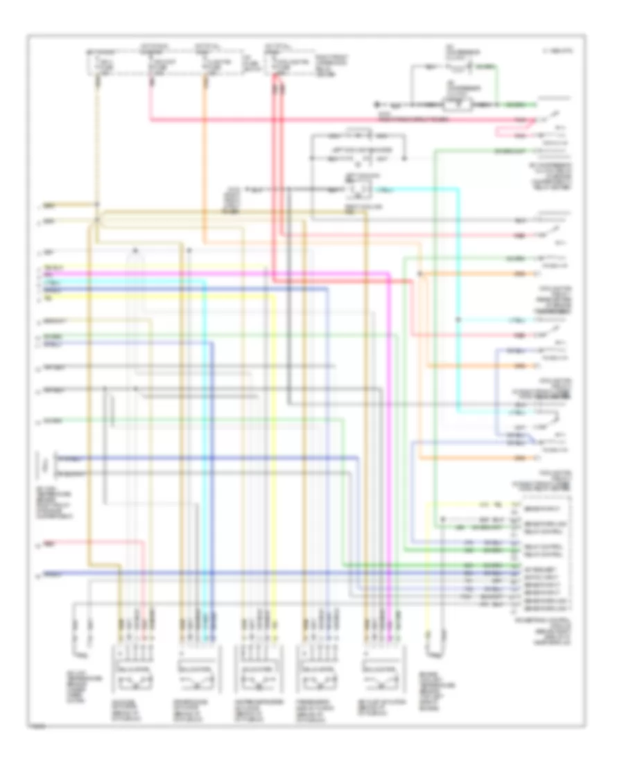
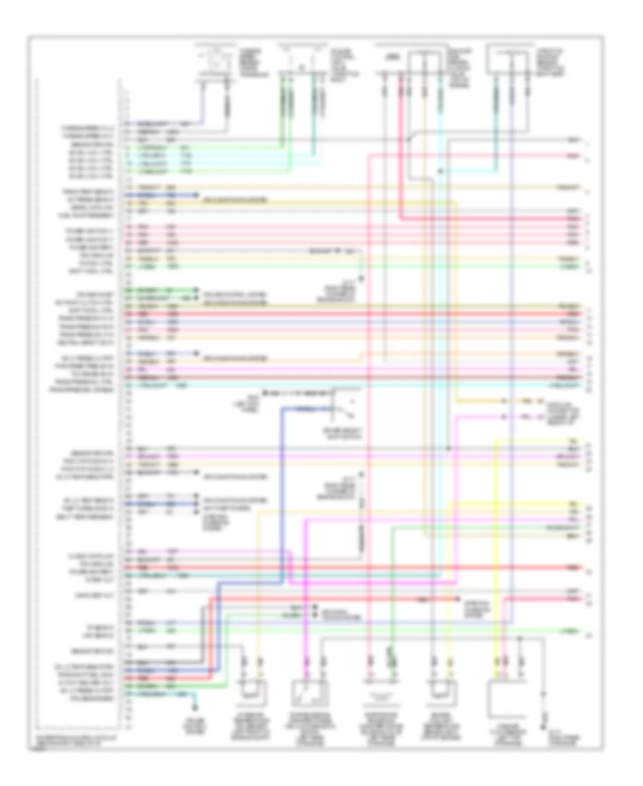
ENGINE PERFORMANCE
4.0L
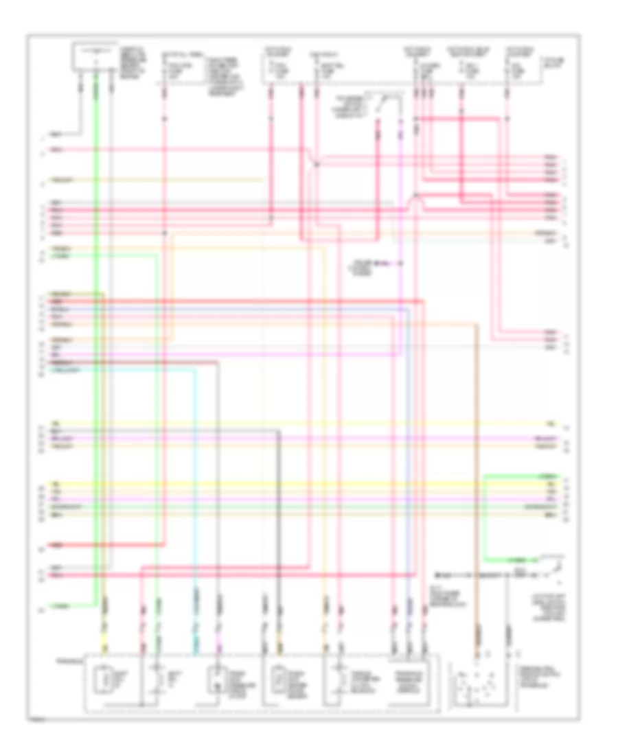
4.0L (VIN C), Engine Performance Wiring Diagrams (1 of 4) for Oldsmobile Aurora 1996
List of elements for 4.0L (VIN C), Engine Performance Wiring Diagrams (1 of 4) for Oldsmobile Aurora 1996:
- 5v ref out
- A/c comp clutch ctrl
- A/c hi press cutoff
- A/c hi temp sens rtrn
- A/c lo press cutoff
- A/c lo temp sens in
- A/c lo temp sens rtrn
- A/c press sens in
- Air condi- tioning system
- Air conditioning system
- Alt out reg ref volt
- Anti-theft system
- Class ii data link
- Cruise control system
- Cruise engaged
- Cruise inhibit
- Data link connector (under left side of i/p)
- Driver select shift switch
- Engine coolant temperature sensor (ect) (top of engine)
- Evap emissions canister purge vacuum diagnostic switch (left rear of engine)
- Evaporative emissions canister purge solenoid valve (left rear of engine)
- Exhaust gas recirc- ulation valve (top of engine)
- Fuel pump feedback
- G117 (right rear corner of engine block)
- G117 (right rear of engine)
- G200 (left kick panel)
- Gen 'f' term feedback
- Iac sol coil ctrl
- Idle air control (iacv) valve (throttle body)
- Intake air temperature (iat) sensor (left front of engine compt)
- Map 5v ref out
- Map sens in
- Mass air flow sensor (left top of engine)
- Neutral safety sw in
- Pcm ground
- Pnk
- Post cat ho2s in hi
- Post cat ho2s in lo
- Power (battery)
- Power (ignition 1)
- Powertrain control module (behind right side of i/p)
- Pwr steer pres sw in
- Red
- Sensor return
- Serial data link
- Shift 'a' sol ctrl
- Shift 'b' sol ctrl
- Starting/ charging system
- Tan
- Tcc brake sw in
- Tcc sol ctrl
- Theft disable sig in
- Throttle position sensor (throttle body assy)
- Tp sens in
- Trans press sol ctrl
- Trans press sol enable
- Trans press sw 'a' in
- Trans press sw 'b' in
- Trans press sw 'c' in
- Trans shift sel indic
- Trans temp sens in
- Turbine speed in hi
- Turbine speed in lo
- Turbine speed sensor (inside transaxle)
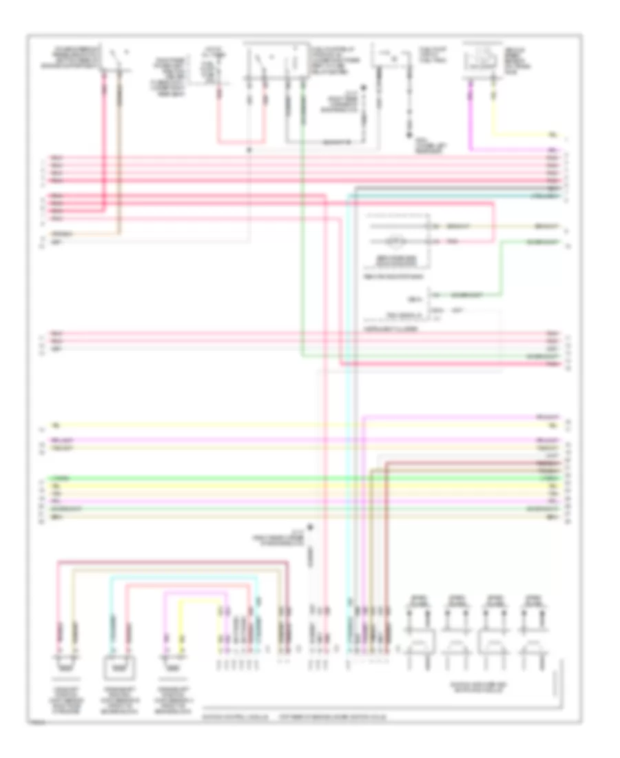
4.0L (VIN C), Engine Performance Wiring Diagrams (2 of 4) for Oldsmobile Aurora 1996
List of elements for 4.0L (VIN C), Engine Performance Wiring Diagrams (2 of 4) for Oldsmobile Aurora 1996:
- Cruise control system
- Dis fuse 15a
- G117 (right rear corner of engine block)
- Hot at all times
- Hot in run
- Hot in run or start
- Hot in run, bulb test or start
- I/p fuse block
- Ign 1 fuse 10a
- Low coolant level switch (radiator coolant surge tank)
- Manifold absolute pressure sensor (front of engine)
- Nca
- Oxy sen fuse 10a
- Park/neutral position switch (top of transaxle)
- Pcm fuse 10a
- Pcm vats fuse 20a
- Pnk
- Red
- Right rear power dist- ribution center maxi fuse block 2 (under right rear seat)
- Shift sol 'a'
- Shift sol 'b"
- Shift sol fuse 10a
- Switch manifold
- Tan
- Tcc brake switch (under left side of i/p)
- Torque converter clutch solenoid
- Trans- axle pressure force motor
- Trans- axle temper- ature sensor
- Transaxle
- Transaxle pressure
4.0L (VIN C), Engine Performance Wiring Diagrams (3 of 4) for Oldsmobile Aurora 1996
List of elements for 4.0L (VIN C), Engine Performance Wiring Diagrams (3 of 4) for Oldsmobile Aurora 1996:
- (not used)
- (top rear of engine under ignition coils)
- B12
- Camshaft position (cmp) sensor (right side of engine)
- Crankshaft position (ckp) sensor a (front of engine block)
- Crankshaft position (ckp) sensor b (front of engine block)
- Fuel pump (top of fuel tank)
- Fuel pump fuse 20a
- Fuel pump relay (position 'e') (under right rear seat, in fuse/ relay center)
- G117 (right rear corner of engine block)
- G304 (under left rear seat)
- Hot at all times
- Ignition amplifier and switching module
- Ignition control module
- Instrument cluster
- Nca
- Pnk
- Power steering pressure switch (bottom rear of engine compartment)
- Red
- Remote indicator bank
- Right rear power dist- ribution center fuse block 1 (under right rear seat)
- Service engine soon indicator
- Spark plugs
- Tach signal in
- Tan
- Vehicle speed sensor (on trans- axle)
- Vss in
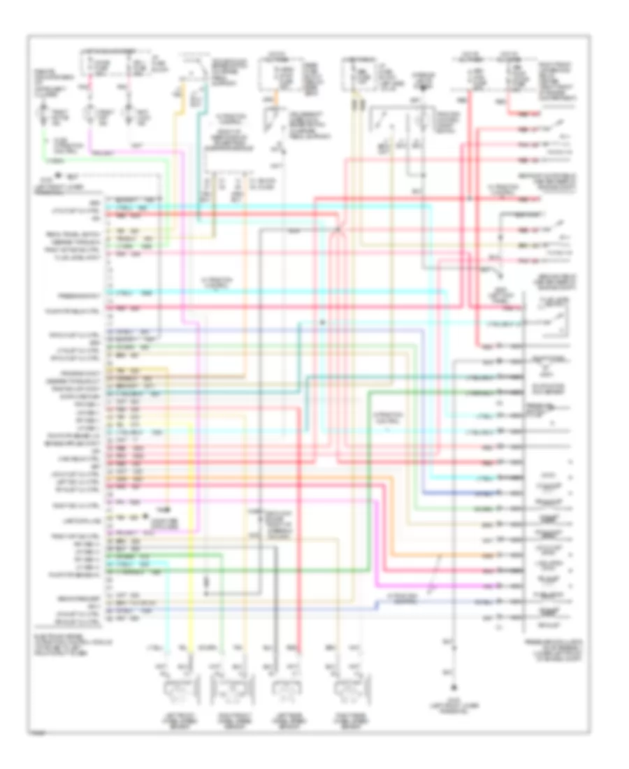
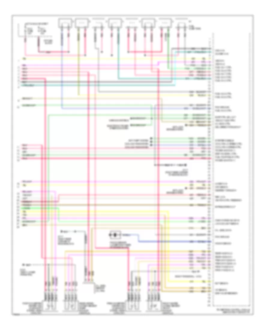
4.0L (VIN C), Engine Performance Wiring Diagrams (4 of 4) for Oldsmobile Aurora 1996
List of elements for 4.0L (VIN C), Engine Performance Wiring Diagrams (4 of 4) for Oldsmobile Aurora 1996:
- (right frame rail)
- 24x ref hi in
- 4x ref hi in
- Anti-lock brakes system
- Anti-theft system
- Bypass spark out
- Cam hi in
- Cann purge vac sw in
- Cool fan hi speed ctrl
- Cool fan lo speed ctrl
- Cooling fans system
- Delivered torque out
- Desired torque in
- Ect sens in
- Egr valve feedback
- Egr valve sol ctrl
- Electronic power steering system
- Evap ctrl sol out
- Front heated oxygen sensor (front exhaust manifold)
- Front ho2s in hi
- Front ho2s in lo
- Fuel inj 1 ctrl
- Fuel inj 2 ctrl
- Fuel inj 3 ctrl
- Fuel inj 4 ctrl
- Fuel inj 5 ctrl
- Fuel inj 6 ctrl
- Fuel inj 7 ctrl
- Fuel inj 8 ctrl
- Fuel injectors
- Fuel pump relay ctrl
- G103
- G103 (right lower frame rail)
- G117 (right rear corner of engine block)
- Hot in run or start
- I/p fuse block
- Iat sens in
- Ignition ctrl feedback
- Inj 1 fuse 10a
- Inj 2 fuse 10a
- Knock sens in
- Knock sensor (lower right rear of engine block)
- Low coolant sens in
- Maf sens in
- Mil indic ctrl
- Nca
- Oil level sensor (oil pan)
- Oil level sw in
- Pcm ground
- Pnk
- Post-converter heated o2s (in exhaust system, near catalyst)
- Power (ignition 1)
- Powertrain control module (behind right side of i/p)
- Pre-cat ho2s in hi
- Pre-cat ho2s in lo
- Pre-converter heated o2s (in exhaust system, near catalyst)
- Rear h02s in lo
- Rear heated oxygen sensor (rear exhaust manifold)
- Rear ho2s in hi
- Ref lo in
- Starter disable
- Tan
- Vss in hi
- Vss in lo
- Vss out (4000 ppm)
- Warning systems
EXTERIOR LIGHTS
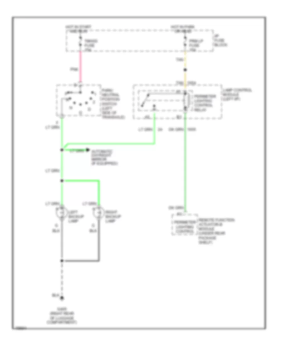
Backup Lamps Wiring Diagram for Oldsmobile Aurora 1996
List of elements for Backup Lamps Wiring Diagram for Oldsmobile Aurora 1996:
- Automatic day/night mirror (if equipped)
- G405 (right rear of luggage compartment)
- Hot in park or head
- Hot in start and run
- I/p fuse block
- Lamp control module (left i/p)
- Left backup lamp
- Park/ neutral position switch (left side of transaxle)
- Perimeter lightimg control
- Perimeter lighting control relay
- Pnk
- Prm lp fuse 15a
- Remote function actuator-b module (under rear package shelf)
- Right backup lamp
- Tan
- Tmnss fuse 15a
Exterior Lamps Wiring Diagram for Oldsmobile Aurora 1996
List of elements for Exterior Lamps Wiring Diagram for Oldsmobile Aurora 1996:
- (left kick
- (right rear of luggage
- A10
- Anti-lock brake system
- Backup lights system
- C12
- Center high mounted stop lamp
- Compartment)
- D12
- G102 (left side of engine compartment)
- G103 (right side of engine compartment)
- G200
- G200 (left kick panel)
- G304 (below left rear seat)
- G304 (under left rear seat)
- G405
- Grd
- Hazard
- Hazard flasher (left i/p)
- Headlamp switch
- Hot at all times
- Hot at hot at all times all times
- Hot in run, and start
- Hzrd/ stop lps fuse 20a
- I/p fuse block
- Instrument cluster
- Interior lights system
- L prk lp fuse 10a
- Lamp control module (left i/p)
- Left corn- ering lamp
- Left front park/ side marker lamp
- Left front park/ turn lamp
- Left license lamp
- Left rear side marker lamp
- Left rear tail/ stop/ turn lamps
- Left turn & hazard
- Left turn ind.
- Nca
- Panel)
- Park lamp switch
- Park lamp switch input
- Park lamps ctrl
- Park lp fuse 15a
- Perimeter lighting control
- Perimeter lighting control relay (left i/p, in lamp control module)
- Pnk
- Prm lp fuse 25a
- R prk lp fuse 10a
- Remote function actuator-b module (under rear packagr shelf)
- Right corn- ering lamp
- Right front park/ side marker lamp
- Right front park/ turn lamp
- Right license lamp
- Right rear power distribution center (left rear of passenger compartment)
- Right rear side marker lamp
- Right rear tail/ stop/ turn lamps
- Right turn & hazard
- Right turn ind.
- Stop lamp/ brake switch (on brake pedal support)
- Tan
- Turn flasher (left i/p)
- Turn lps fuse 15a
- Turn/ hazard switch assembly
- Warning systems
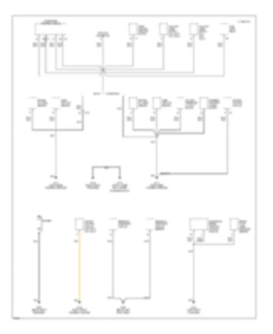
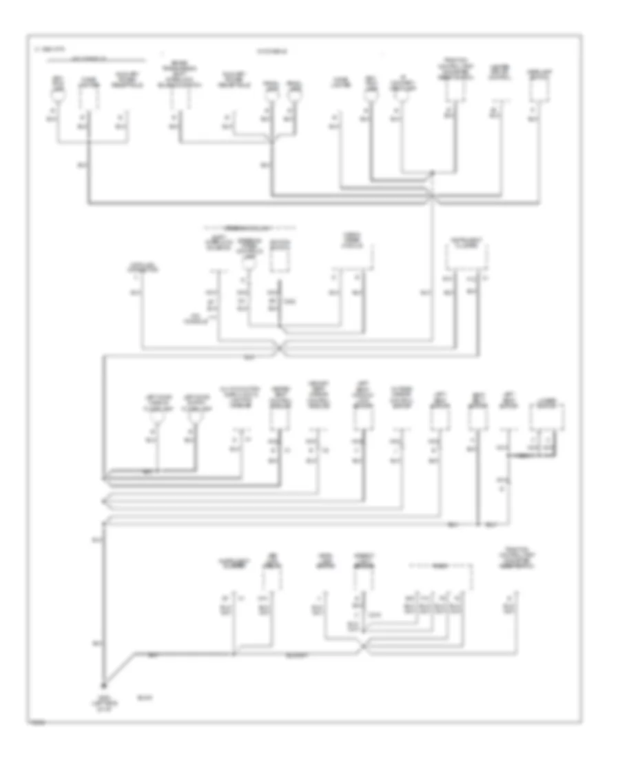
GROUND DISTRIBUTION
Ground Distribution Wiring Diagram (1 of 5) for Oldsmobile Aurora 1996
List of elements for Ground Distribution Wiring Diagram (1 of 5) for Oldsmobile Aurora 1996:
- 1995 vftc c
- A/c high pressure cut-out switch
- Battery
- Brake fluid level indicator sensor
- Buick
- C101
- Coolant level switch (3.8l vin k/ vin 1 only)
- Coolant level switch (4.0l vin c only)
- Data link connector
- Electronic brake/ traction control module
- Engine oil level sensor
- Evap/ems canistor purge switch
- Fuel pump relay
- G110 (left front of engine)
- G117 (right rear corner of engine)
- G119 (right front corner of engine)
- G119 (right front of engine)
- G119 (right lower rail, foward
- G300 (below left front seat)
- G303 (below right rear seat)
- Ignition control module
- Ignition control module (3.8l vin k/ vin 1 only)
- Mass air flow sensor
- Nca
- Of engine mount)
- Oldsmobile
- Park/ neutral position switch
- Powertrain control module
- Sensing & diagnostic module
- Sensing & diagnostic module sensor
- Tan
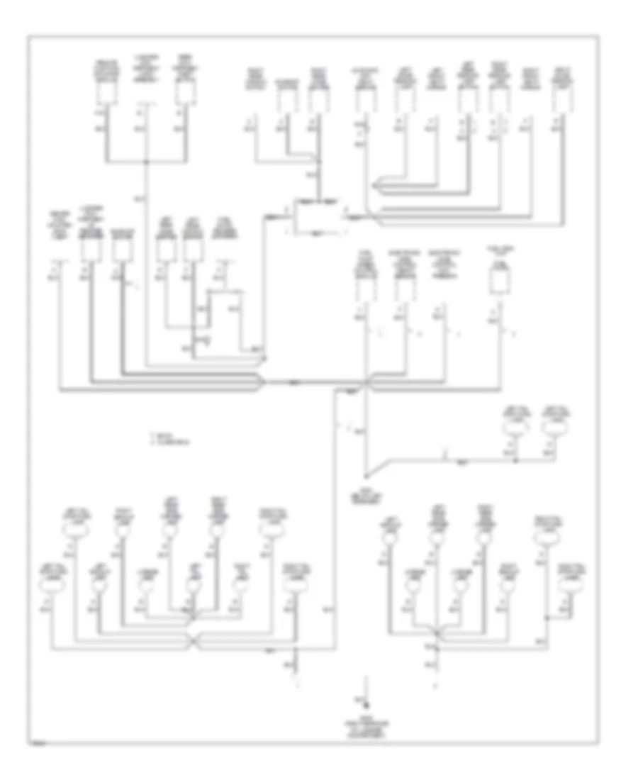
Ground Distribution Wiring Diagram (2 of 5) for Oldsmobile Aurora 1996
List of elements for Ground Distribution Wiring Diagram (2 of 5) for Oldsmobile Aurora 1996:
- 1995 vftc c
- A/c com- pressor clutch
- A/c comp- ressor clutch diode
- B10
- Blower control module
- Blower motor
- Buick
- C125
- C126
- C502
- C505
- C602
- C605
- Cooling fan relay #3
- Cruise module
- D16
- Engine com- part- ment lamp
- G103 (right side of engine compartment)
- G110 (left front of engine)
- G203 (right kick panel)
- High speed coolant fan motor
- Hvac pro- grammer
- Instrument cluster
- Left cornering lamp
- Left door lock cylinder switch
- Left front door jamb switch
- Left front door switches
- Left front heated oxygen sensor
- Left front park/ turn lamp
- Left high beam headlamp
- Left horn (f note)
- Left lock switch
- Left low beam headlamp
- Left rear door jamb switch
- Lumbar control module
- Nca
- Oldsmobile
- Pass- enger climate control assembly
- Passkey ii decoder module
- Post converter heated oxygen sensor
- Pre converter heated oxygen sensor
- Pressure modulator valve assembly
- Pump motor
- Right cornering lamp
- Right door handle flood lamp
- Right door jamb switch
- Right door lock cylinder switch
- Right door switch flood lamp
- Right door switches
- Right fog lamp
- Right front door jamb switch
- Right front door lock actuator
- Right front park/ turn lamp
- Right front window switch
- Right heated seat control module
- Right high beam headlamp
- Right horn (a note)
- Right lock switch
- Right low beam headlamp
- Right outside mirror
- Right rear door jamb switch
- Right rear heated oxygen sensor nca
- Right seat switch
- Washer fluid level switch
- Wiper motor module
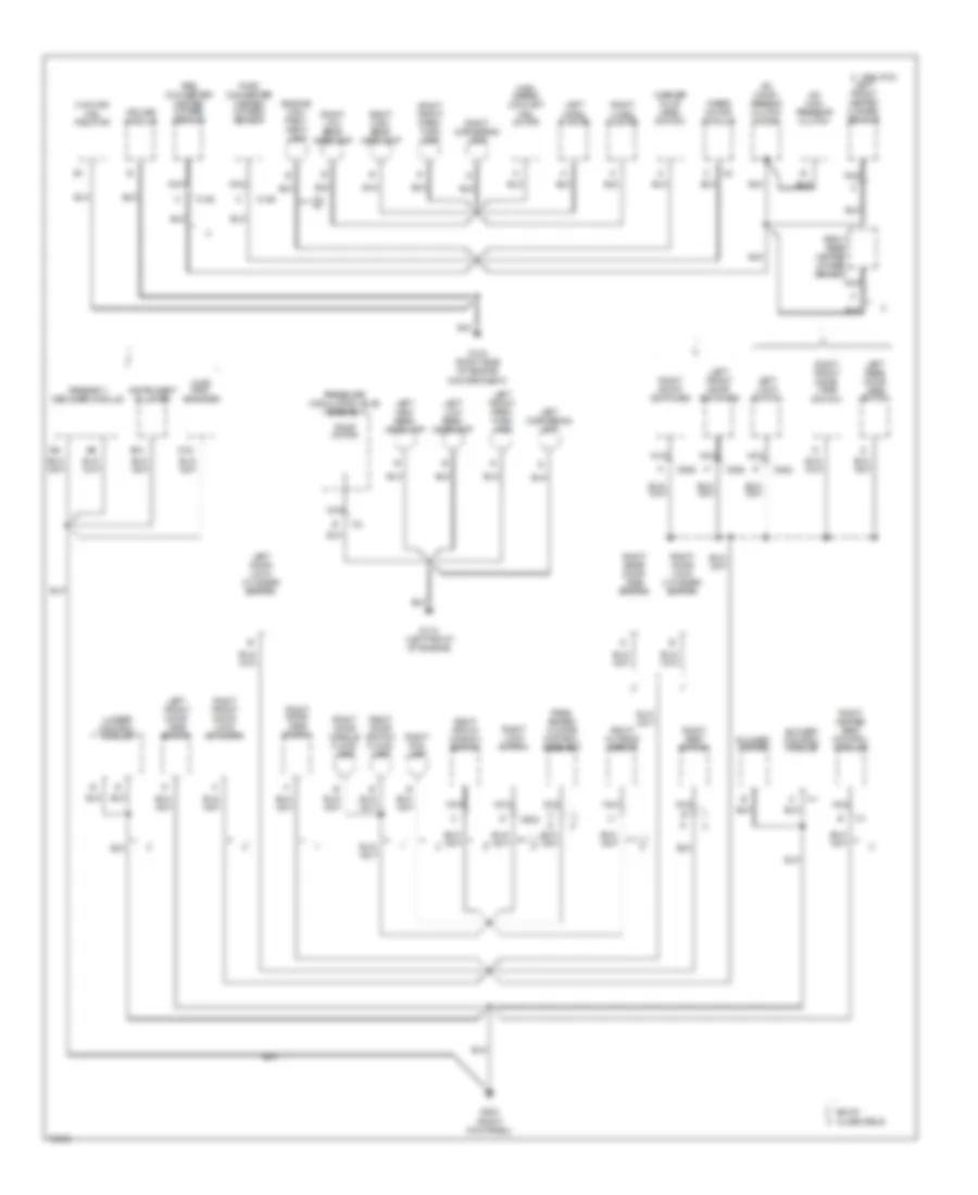
Ground Distribution Wiring Diagram (3 of 5) for Oldsmobile Aurora 1996
List of elements for Ground Distribution Wiring Diagram (3 of 5) for Oldsmobile Aurora 1996:
- 1995 vftc c
- 87a
- Abs main relay
- Ambient light sensor
- Amplifier/ sub-woofer
- Ash- tray lamp
- Auxiliary power receptacle
- Brake transmission shift interlock solenoid
- C12
- C212
- Compact disc player
- Console compart- ment lamp switch
- D12
- Data link connector
- Driver information center/ hvac controller
- E16
- Fog lamp switch
- Front cigar lighter
- Fuel door release switch
- G202 (left side of i/p)
- Head- lamp switch
- I/p compart- ment lamp switch
- Ignition switch
- Instrument cluster
- Lamp control module
- Left fog lamp
- Left heated seat control module
- Left outside mirror
- Left seat switch
- Magna steer module
- Master switch assembly
- Memory seat/ mirror control module
- Multi-function alarm lock & lighting module
- Nca
- Oldsmobile
- Outside mirror control switch
- Panel dimming switch
- Prndl illum- nation
- Prndl lamp
- Radio
- Seat belt switch
- Shift select switch
- Steering column
- Steering wheel controls lamp
- Traction control switch
- W/ steering wheel controls only
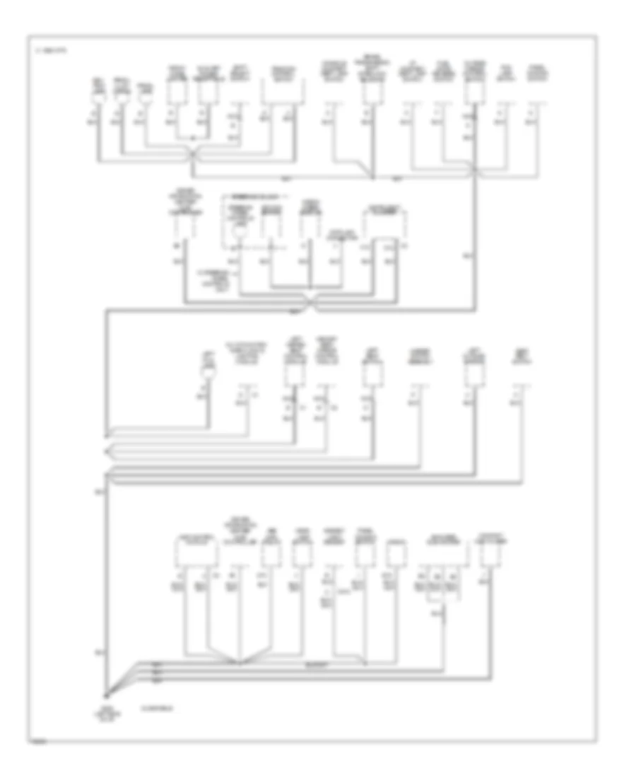
Ground Distribution Wiring Diagram (4 of 5) for Oldsmobile Aurora 1996
List of elements for Ground Distribution Wiring Diagram (4 of 5) for Oldsmobile Aurora 1996:
- 1995 vftc c
- 87a
- Abs main relay
- Ambient light sensor
- Ash- tray lamp
- Auxiliary power receptacle
- Brake transmission shift interlock solenoid switch
- Buick
- C202
- C219
- Cigar lighter
- Data link connector
- E12
- E16
- F10
- F12
- G202 (left side of i/p)
- Head- lamp switch
- Headlamp switch
- Heated seat control module
- Heater and a/c control
- I/p compart- ment lamp
- Ignition switch
- Instrument cluster
- Left door handle flood lamp
- Left door switch flood lamp
- Left seat switch
- Left seat/ window/ lock switch
- Lumbar switch
- Magna steer module
- Memory seat/ mirror control module
- Multi-function alarm lock & lighting module
- Nca
- Outside mirror control switch
- Prndl lamp
- Radio
- Seat belt switch
- Shift interlock solenoid
- Steering column
- Steering wheel controls lamp
- Traction control/trip odometer reset switch
- W/ console
- W/o console
Ground Distribution Wiring Diagram (5 of 5) for Oldsmobile Aurora 1996
List of elements for Ground Distribution Wiring Diagram (5 of 5) for Oldsmobile Aurora 1996:
- Automatic day/ night mirror
- Buick
- Center high mounted stop lamp
- Electronic level control com- pressor
- Electronic level control height sensor
- F16
- Fuel door release actuator
- Fuel pump
- Fuel pump speed control module
- Fuel tank unit
- G304 (below left rear seat)
- G405 (right rear side of luggage compartment)
- Left backup lamp
- Left dome/ reading lamp
- Left front vanity mirror
- Left rear cigar lighter
- Left rear reading lamp switch
- Left rear side marker lamp
- Left rear window switch
- Left tail lamp
- Left tail/ stop/turn lamp
- License lamp
- Luggage com- partment latch assembly
- Luggage com- partment lid release actuator
- Nca
- Oldsmobile
- Rear com- partment theft switch
- Remote function actuator module
- Right backup lamp
- Right dome/ reading lamp
- Right front vanity mirror
- Right rear cigar lighter
- Right rear reading lamp switch
- Right rear side marker lamp
- Right rear window switch
- Right tail lamp
- Right tail/ stop/turn lamp
- Sunroof motor
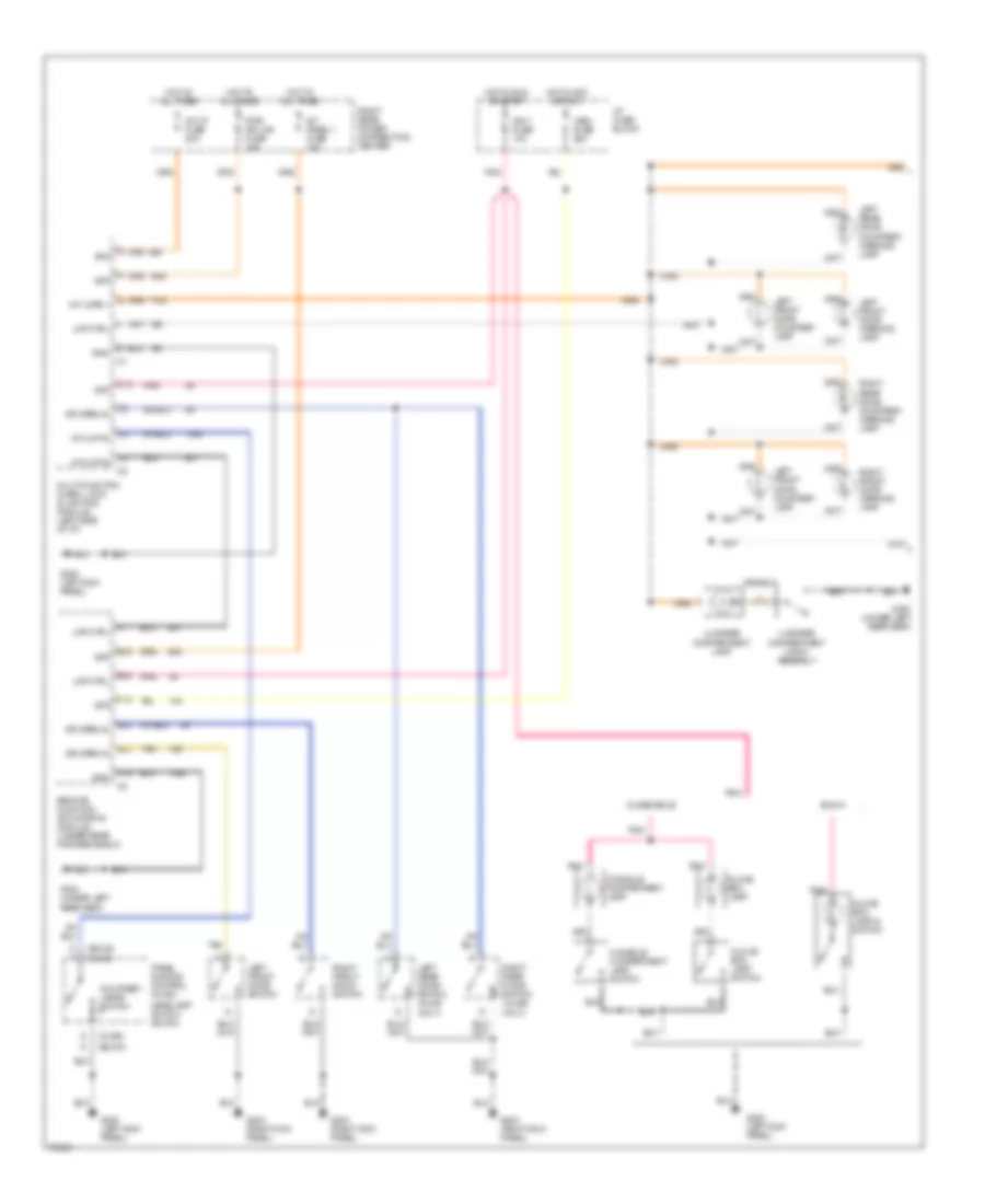
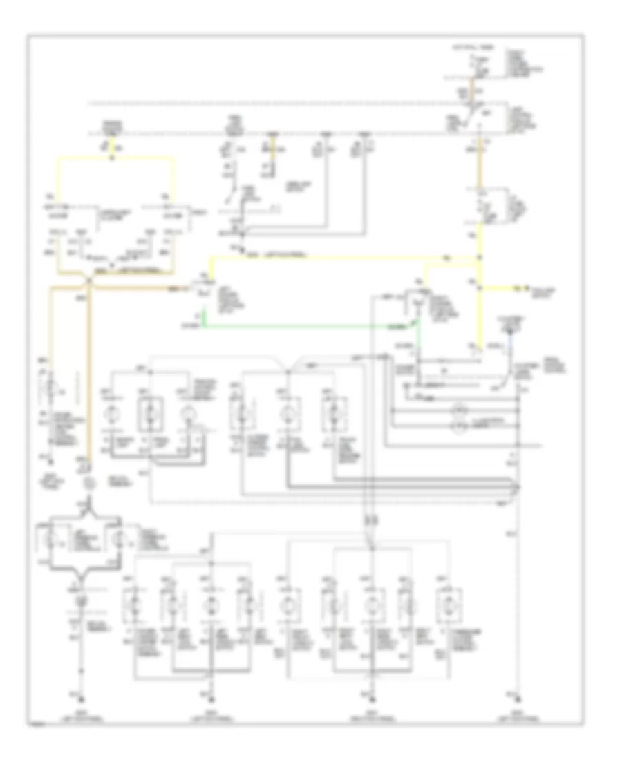
HEADLIGHTS
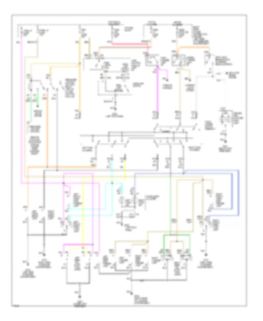
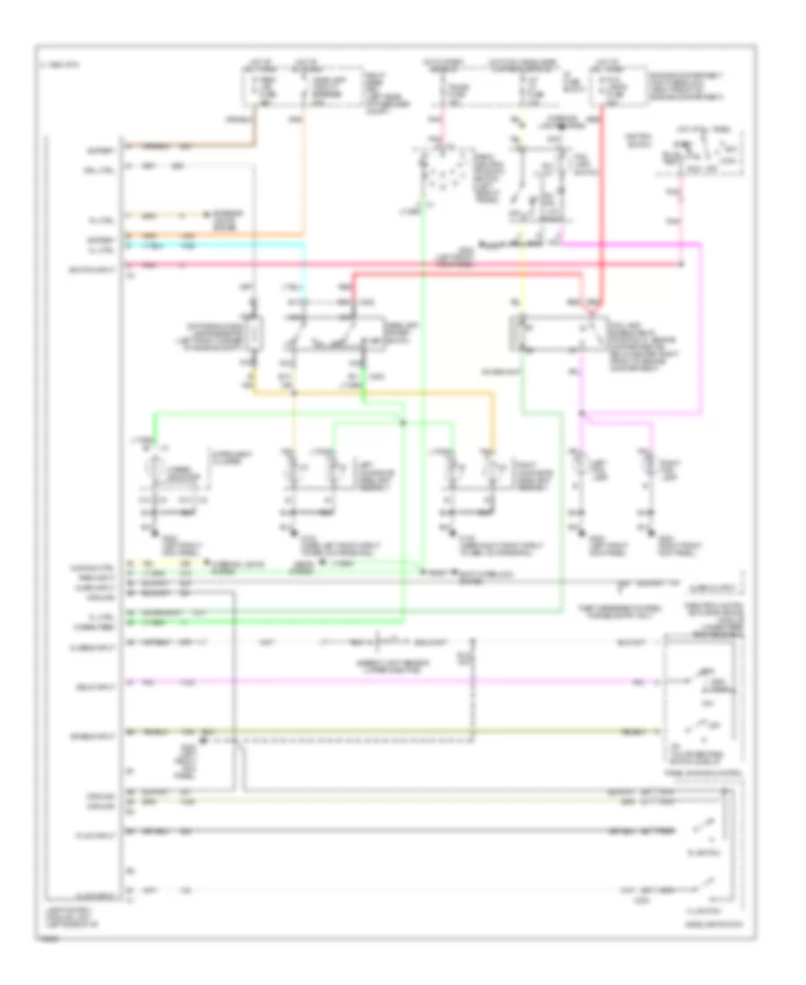
Headlight Wiring Diagram, with Twilight Sentinel / DRL for Oldsmobile Aurora 1996
List of elements for Headlight Wiring Diagram, with Twilight Sentinel / DRL for Oldsmobile Aurora 1996:
- alarm output
- 10a
- 15a
- 200k ohms
- 20a
- 25a
- Acc
- Al sens input
- Alarm input
- Ambient light sensor (upper dash pad)
- Battery
- Bulb test
- C 1995 vftc
- C c1
- C12
- C202
- D12
- Daytime running lamps resistor (left front corner of engine compt.)
- Delay input
- Dimming ctrl
- Drl ctrl
- E10
- E11
- E12
- E13
- Enable input
- Engine compartment maxi fuse block (right front of engine compartment)
- Exterior lights system
- Fl ctrl
- Flash
- Fog lamp enable relay (position 'c', engine compartment #2 relay center, right front of engine compartment)
- Fog lamp switch
- Fog lamps fuse
- G102 (near left front strut tower, on frame rail)
- G103 (near right front strut tower, on frame rail)
- G200 (left front kick panel)
- G203 (right front kick panel)
- Ground
- Headlamp circuit breaker
- Headlamp dimmer switch
- Headlamp switch
- Hi beam feed
- Hi beam indicator
- Hl ctrl
- Hl sw input
- Hl switch
- Hot at all times
- Hot in start and run
- Hot with headlamps or park lamps on
- I/p fuse block
- Ignition input
- Ignition switch
- Instrument cluster
- Int lp fuse
- Interior lights system
- Lamp control module (lcm) (left side of i/p)
- Left composite headlamp assembly
- Left fog lamp
- Lock
- Max
- Min
- Nca
- Off
- Ohm
- On ind
- On twilite sentinel switch & delay
- Panel dimming control
- Park input
- Park lps fuse
- Park/ neutral position switch (left side of trans.)
- Pl ctrl
- Pl sw input
- Pl switch
- Pnk
- Pnk d c1
- Red
- Remote function actuator (rfa-b) module (under rear package shelf)
- Right composite headlamp assembly
- Right fog lamp
- Right rear pdc (left rear of passnger. compt.)
- Run
- Seats system
- Shift interlock system
- Start
- Sw illum
- Tan
- Tan a
- Theft deterrent system: forced entry only
- Tmmss fuse
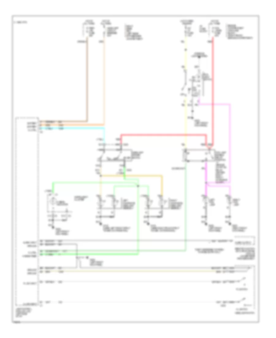
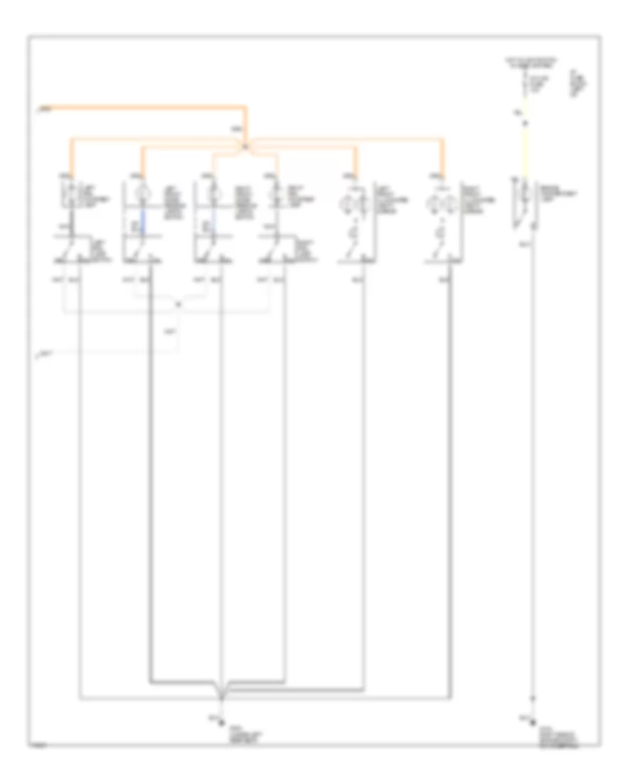
Headlight Wiring Diagram, without DRL/Twilight Sentinel for Oldsmobile Aurora 1996
List of elements for Headlight Wiring Diagram, without DRL/Twilight Sentinel for Oldsmobile Aurora 1996:
- alarm output
- Alarm input
- Battery
- C 1995 vftc
- C12
- C202
- D12
- E10
- E11
- E12
- E13
- Engine compartment maxi fuse block (right front engine compartment)
- Fl ctrl
- Flash
- Fog lamp enable relay position "c" (engine compt. #2 relay center: right front of engine compt.)
- Fog lamp switch
- Fog lamps fuse 20a
- G102 (near left front strut tower, on frame rail)
- G103 (near right front strut tower, on frame rail)
- G200 (left front kick panel)
- G203 (right front kick panel)
- Ground
- Headlamp circuit breaker 20a
- Headlamp dimmer switch
- Headlamp switch
- Hi beam feed
- Hi beam indicator
- Hl ctrl
- Hl sw input
- Hl switch
- Hot at all times
- Hot in park or head
- I/p fuse block
- Instrument cluster
- Int lp fuse 10a
- Interior lights system
- Lamp control module (lcm) (left side of i/p)
- Left composite headlamp assembly
- Left fog lamp
- Nca
- Off
- Ohm
- On ind
- Park lps fuse 25a
- Pl sw input
- Pl switch
- Red
- Remote function actuator (rfa-b) module (under rear package shelf)
- Right composite headlamp assembly
- Right fog lamp
- Right rear pdc (left rear of passnger. compartment)
- Sw illum
- Tan
- Tan a
- Theft deterrent system: forced entry only
HORN
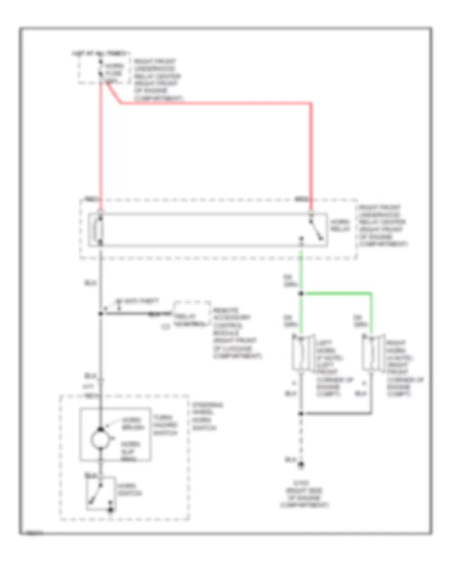
Horn Wiring Diagram for Oldsmobile Aurora 1996
List of elements for Horn Wiring Diagram for Oldsmobile Aurora 1996:
- A11
- Control module (right front
- G103 (right side of engine compartment)
- Horn brush
- Horn fuse 20a
- Horn relay
- Horn slip ring
- Horn switch
- Hot at all times
- Left horn (f note) (left front corner of engine compt)
- Nca
- Of luggage compartment)
- Red
- Relay control
- Remote accessory
- Right front underhood relay center (right front of engine compartment)
- Right horn (a note) (right front corner of engine compt)
- Steering wheel
- Switch
- Turn/ hazard
- W/ anti-theft
INSTRUMENT CLUSTER
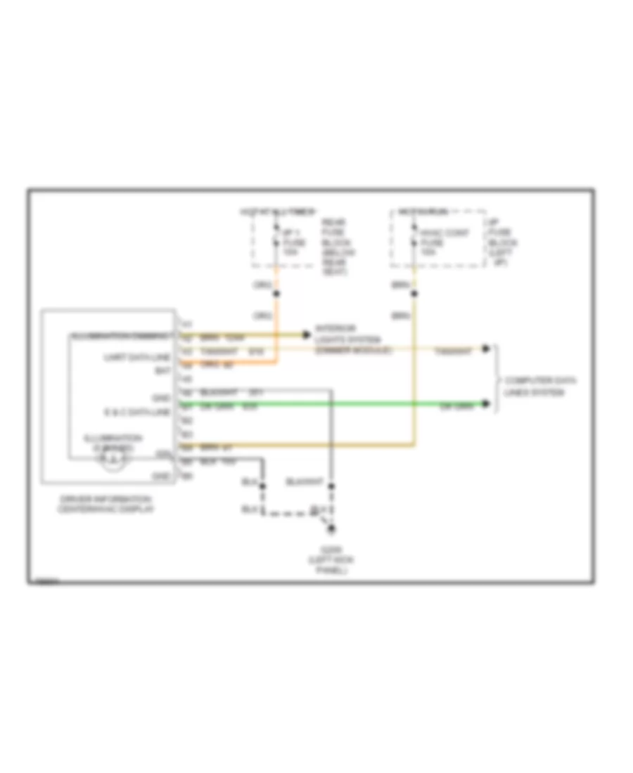
Driver Information Center Wiring Diagram for Oldsmobile Aurora 1996
List of elements for Driver Information Center Wiring Diagram for Oldsmobile Aurora 1996:
- Bat
- Computer data
- Driver information center/hvac display
- E & c data line
- G200 (left kick panel)
- Gnd
- Hot at all times
- Hot in run
- Hvac cont fuse 10a
- I/p 1 fuse 10a
- I/p fuse block (left
- I/p)
- Ign
- Illumination (6 bulbs)
- Illumination dimming
- Interior
- Lights system (dimmer module)
- Lines system
- Rear fuse block (below rear seat)
- Uart data line
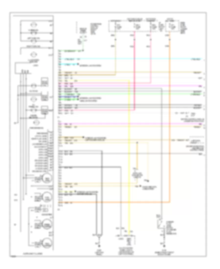
Instrument Cluster Wiring Diagram (1 of 2) for Oldsmobile Aurora 1996
List of elements for Instrument Cluster Wiring Diagram (1 of 2) for Oldsmobile Aurora 1996:
- A10
- A11
- A12
- Aux chime out
- B10
- B11
- B12
- Bat
- C10
- C12
- C13
- C14
- C15
- C16
- Computer data lines system
- Cruise ind. ctrl
- D10
- D11
- D12
- D13
- D14
- D15
- D16
- Data line
- Data link connector (left i/p)
- Dim level
- Driver information center/hvac control panel
- Exterior lights system
- Fasten belts ind.
- Fuel gage
- G103 (base of right front shock tower)
- G200 (left kick panel)
- Grd
- Headlights system
- Hi beam ind.
- Hot at all times
- Hot in run
- Hot in run or start
- Hot in run, bulb test or start
- I/p 1 fuse 10a
- I/p 3 fuse 10a
- I/p fuse block (left
- I/p)
- Ign
- Ign 1 fuse 10a
- Ignition control module (under ignition coils)
- Illumination (6 bulbs)
- Instrument cluster
- Interior lights system (dimmer module)
- Interior lights system (left dimmer module)
- Left turn ind.
- Lf door ajar
- Logic
- Low brake fluid
- Low oil level
- Lr door ajar
- Multi-function alarm, lock & lighting module (left kick panel)
- Odometers
- Oil press. ind.
- Park brake
- Park brake ind.
- Pcm fuse 10a
- Pnk
- Powertrain control module (right side of i/p)
- Rear fuse block (under rear seat)
- Rf door ajar
- Right turn ind.
- Rr door ajar
- Seat belt ind ctrl
- Solid state ctrl
- Speed- ometer
- Tach out
- Tach- ometer
- Tan
- Temp gage
- Uart data in/out
- Vehicle speed output
- Volts ind.
- Washer fluid level switch (in washer fluid reservoir)
- Wshr fluid level
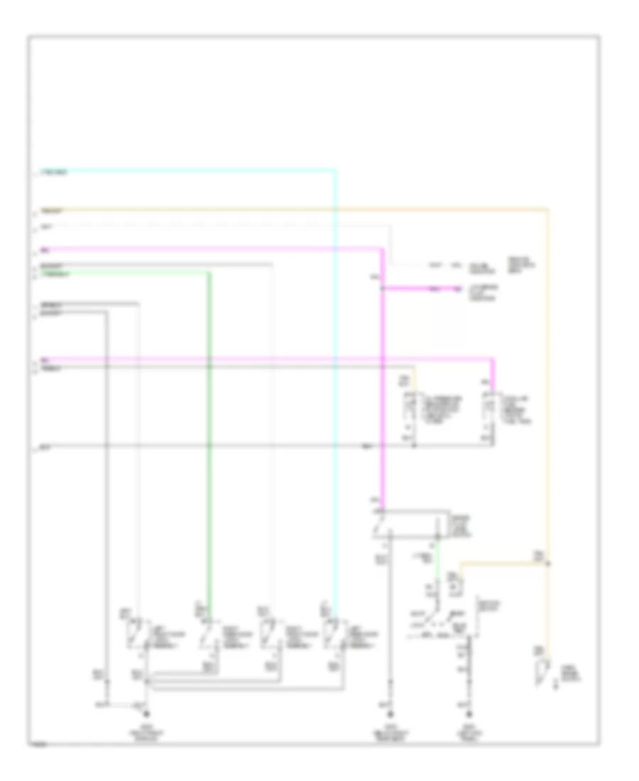
Instrument Cluster Wiring Diagram (2 of 2) for Oldsmobile Aurora 1996
List of elements for Instrument Cluster Wiring Diagram (2 of 2) for Oldsmobile Aurora 1996:
- A10
- Accy
- Brake fluid level switch
- Bulb test
- Cruise indicator
- G200 (left kick panel)
- G203 (right front shroud)
- G303 (below right rear seat)
- Ignition switch
- Left front door latch assembly
- Left rear door latch assembly
- Lock
- Low brake fluid indicator
- Modular fuel sender (top of fuel tank)
- Nca
- Off
- Oil pressure sensor/fuel pump switch (above oil filter)
- Park brake switch
- Remote indicator bank
- Right front door latch assembly
- Right rear door latch assembly
- Run
- Start
Remote Indicator Bank Wiring Diagram for Oldsmobile Aurora 1996
List of elements for Remote Indicator Bank Wiring Diagram for Oldsmobile Aurora 1996:
- A10
- A11
- A12
- Air bag ind.
- Anti-lock brake system
- Anti-lock diode (right of steering column)
- Anti-lock ind req
- Anti-lock ind.
- B10
- B11
- B12
- Brake fluid level indicator switch
- Cruise ind ctrl
- Cruise ind.
- Electronic brake & traction control module (attached to left front strut tower)
- Hazard flasher
- Hazard ind.
- Hot at all times
- Hot in run, bulb test or start
- I/p 1 fuse 10a
- I/p fuse block (left
- I/p)
- Ign 1 fuse 10a
- Indtrument cluster
- Instrument cluster
- Low brake fluid in
- Low brake fluid ind.
- Mil ind ctrl
- Nca
- Passkey ii decoder module (right side of i/p)
- Pnk
- Powertrain control module (right i/p, near shroud)
- Rear fuse block (below rear seat)
- Red
- Remote functional actuation module (right front of luggage compt.)
- Remote indicator bank
- Security ind ctrl
- Security ind.
- Sensing & diagnostic module (below left front seat)
- Service engine soon ind.
- Sir ind ctrl
- Trac active ind ctrl
- Trac off ind ctrl
- Traction active ind.
- Traction off ind.
- Turn/ hazard switch assembly
INTERIOR LIGHTS
Courtesy Lamps Wiring Diagram (1 of 2) for Oldsmobile Aurora 1996
List of elements for Courtesy Lamps Wiring Diagram (1 of 2) for Oldsmobile Aurora 1996:
- (buick)
- (olds)
- Bat
- Buick
- C13
- Console compartment lamp
- Console compartment lamp switch
- Courtesy lamps switch
- Dr open in
- E10
- E12
- E15
- E16
- F15
- F16
- G200 (left kick panel)
- G203 (right kick panel)
- G304 (under left rear seat)
- Glove box lamp
- Glove box lamp & switch
- Glove box lamp switch
- Gnd
- Headlamp switch (buick)
- Hot at all times
- Hot in acc or run
- Hot in run or start
- I/p fuse block
- Ign 1 fuse 10a
- Int lmp in
- Int lmps +
- Int lp fuse 20a
- Int panel 1 fuse 10a
- Left
- Left front door courtesy lamp
- Left front door switch
- Left front door warning lamp
- Left rear door switch (olds only)
- Lmp ctrl
- Luggage compartment lamp
- Luggage compartment latch assembly
- Multi-function alarm, lock & lighting module (left side of i/p)
- Oldsmobile
- Panel dimming control (olds)
- Pnk
- Pwr dr lks fuse 15a
- Rear door courtesy/ warning lamp
- Remote function actuator-b module (under rear package shelf)
- Right
- Right front door switch
- Right front door warning lamp
- Right rear door switch (olds) only)
- Right rear power distribution center
- Tan
- Wsw fuse 25a
Courtesy Lamps Wiring Diagram (2 of 2) for Oldsmobile Aurora 1996
List of elements for Courtesy Lamps Wiring Diagram (2 of 2) for Oldsmobile Aurora 1996:
- Engine compartment lamp
- G103 right side of engine compt., on lower rail)
- G304 (under left rear seat)
- Hot w/light switch in head or park
- I/p fuse block (left i/p)
- Int lps fuse 10a
- Left front dome/ reading lamp & switch
- Left front illuminated vanity mirror
- Left rail courtesy lamp
- Left rail lamp switch
- Nca
- Right front dome/ reading lamp & switch
- Right front illuminated vanity mirror
- Right rail courtesy lamp
- Right rail lamp switch
Instrument Illumination Wiring Diagram for Oldsmobile Aurora 1996
List of elements for Instrument Illumination Wiring Diagram for Oldsmobile Aurora 1996:
- (2)
- (6)
- (left kick panel)
- Ashray lamp
- Bat
- Bright
- Courtesy lamps switch
- Courtesy lights circuit
- D11
- D12
- Dim
- Dim lvl
- Dim ref
- Dimmer switch
- Driver information center/ hvac control assembly
- E16
- Fog lamp switch
- G200
- G200 (left kick panel)
- G201 (right kick panel)
- Gnd
- Headlamp switch
- Hot at all times
- I/p fuse block (left i/p)
- Illumination lamps
- Instrument cluster
- Int lp fuse 10a
- Lamp control module (left side of i/p)
- Left dimmer module (left side of i/p)
- Left rear window switch
- Left seat switch
- Left seat/ lock switch
- Left steering wheel controls
- Nca
- Off
- Outside mirror control switch
- Panel dimming control
- Parade dimming ctrl
- Park lamp switch
- Park lamp switch input
- Park lamps ctrl
- Park lp fuse 25a
- Passenger climate control assembly
- Power window master switch assembly
- Prndl lamp
- Radio
- Right dimmer module (left side of i/p)
- Right front window switch
- Right rear power distribution center
- Right rear window switch
- Right seat switch
- Right seat/ lock switch
- Right steering wheel controls
- Sir coil assembly
- Traction control on/off switch
- Trunk/ fuel door release switch
MEMORY SYSTEMS
Memory Seat/Mirrors Wiring Diagram (1 of 2) for Oldsmobile Aurora 1996
List of elements for Memory Seat/Mirrors Wiring Diagram (1 of 2) for Oldsmobile Aurora 1996:
- 10a
- Battery
- C10
- C11
- C12
- C13
- C14
- C15
- C16
- Chime fuse 10a
- D nca
- D10
- D11
- D12
- D13
- D14
- D15
- D16
- Diagnostic connector
- Diagnostic test
- Driver recline-aft
- Driver recline-fore
- E.c.b.
- Entire seat back
- Entire seat back input
- Entire seat forward
- Entire seat fwd input
- Forward/back control
- Forward/back motor (below left front seat)
- Forward/back motor transmission (below left front seat)
- Front height
- Front height control
- Front height down
- Front height down input
- Front height motor (below left front seat)
- Front height motor position sensor
- Front height motor transmission (below left front seat)
- Front height up input
- Frt height mtr pos input
- Fwd/back mtr pos input
- G200 (left kick- panel)
- Ground
- Hot at all times
- Hot in run or start
- I/p 1 fuse
- I/p fuse block
- Ignition input
- Illum- ination lamp
- Interior lights system
- Left mirror down input
- Left mirror right input
- Left seat switch
- Left seat/lock switch
- Left-right position input
- Memory 1 input
- Memory 2 input
- Memory position switch 1
- Memory position switch 2
- Memory seat/memory mirror control module (under left front seat)
- Mirror left input
- Mirror up input
- Nca
- Park input
- Park/neutral position switch (left rear of engine, left side of transaxle)
- Pnk
- Position sensors input
- Position sensors return
- Pwr st circuit breaker 25a
- Rear height control
- Rear height down
- Rear height down input
- Rear height motor (below left front seat)
- Rear height motor position sensor
- Rear height motor transmission (below left front seat)
- Rear height up
- Rear height up input
- Recline control
- Recline motor (below left front seat)
- Recline motor position sensor
- Recline motor transmission (below left front seat)
- Recline mtr pos input
- Right mirror down input
- Right mirror right input
- Right rear power distribution center fuse block 2 (under left rear seat)
- Rr height mtr pos input
- Set memory input
- Set memory switch
- Tan
- Tmnss fuse 15a
- Up-down position input
Memory Seat/Mirrors Wiring Diagram (2 of 2) for Oldsmobile Aurora 1996
List of elements for Memory Seat/Mirrors Wiring Diagram (2 of 2) for Oldsmobile Aurora 1996:
- B10
- C10
- G200 (left kick panel)
- G200 (left kick- panel)
- Illumination lamp
- Interior lights system
- Left
- Left outside mirror
- Left seat switch
- Left- right motor
- Left-right motor cntr
- Memory seat/memory mirror control module (under left front seat)
- Mirror down switch
- Mirror left switch
- Mirror position sensors
- Mirror right switch
- Mirror select switch
- Mirror up switch
- Nca
- Outside mirror control switch
- Recline down
- Recline up
- Right
- Right outside mirror
- Up- down motor
- Up-down motor cntr
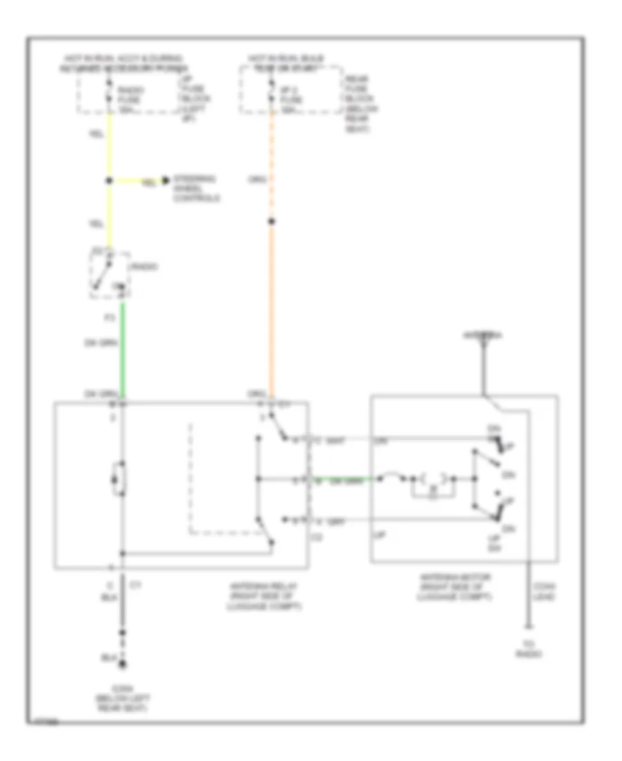
POWER ANTENNA
Power Antenna Wiring Diagram for Oldsmobile Aurora 1996
List of elements for Power Antenna Wiring Diagram for Oldsmobile Aurora 1996:
- Antenna
- Antenna motor (right side of luggage compt)
- Antenna relay (right side of luggage compt)
- Coax lead
- Dn sw
- G304 (below left rear seat)
- Hot in run, accy & during retained accessory power
- Hot in run, bulb test or start
- I/p 2 fuse 10a
- I/p fuse block (left i/p)
- Radio
- Radio fuse 15a
- Rear fuse block (below rear seat)
- Steering wheel controls
- To radio
- Up sw
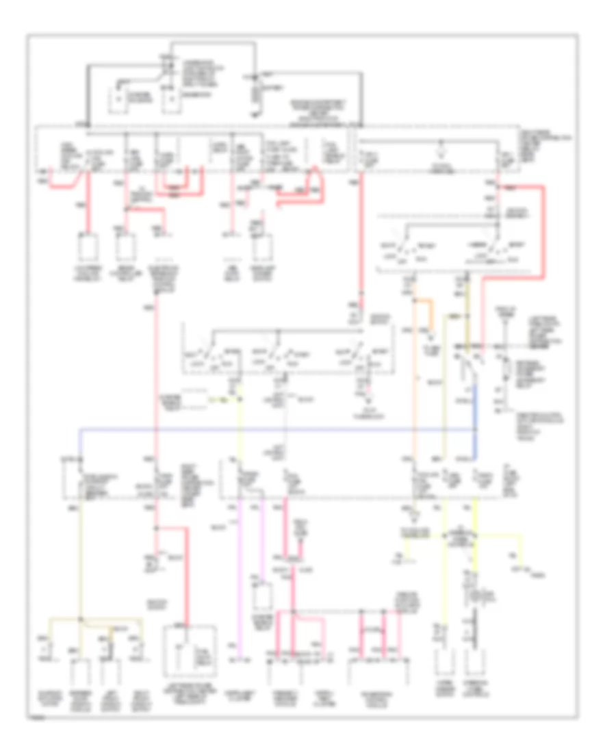
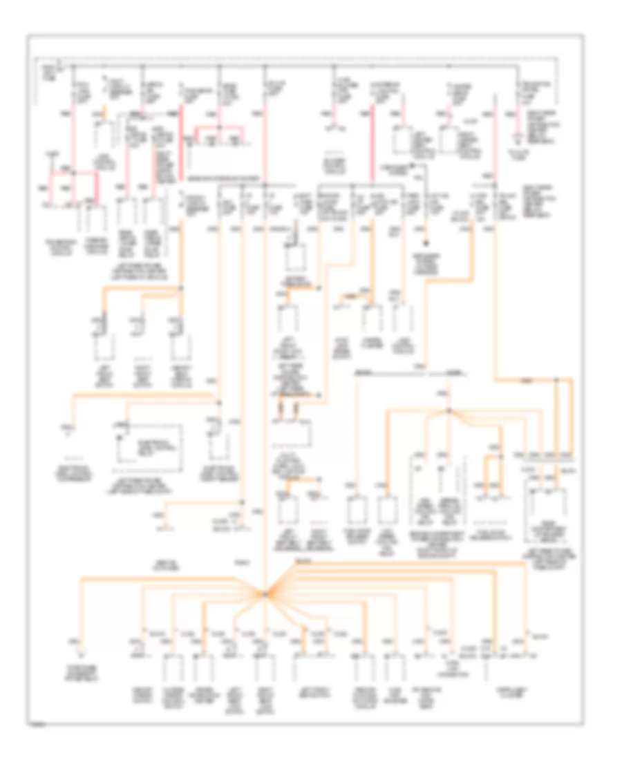
POWER DISTRIBUTION
Power Distribution Wiring Diagram (1 of 4) for Oldsmobile Aurora 1996
List of elements for Power Distribution Wiring Diagram (1 of 4) for Oldsmobile Aurora 1996:
- (buick)
- (left rear pass compt)
- (olds)
- 15a
- 20a
- Abs main fuse 30a
- Abs pump motor fuse 40a
- Abs pump relay
- Accy
- Battery
- Brake controller relay
- Buick
- Cooling fan fuse 10a (buick)
- Cooling fan fuse 60a
- Crank fuse 10a
- E10
- Electronic brake and traction control module
- Engine compartment power distribution center (right front of engine compartment)
- Express down window module
- F/pmp fuse 20a
- F15
- Flash-to pass fuse
- Fog lamp enable relay
- Fog lamp fuse
- From i/p 1 fuse
- From pcm fuse
- Fuel pump relay
- Generator
- Headlamp dimmer switch
- High speed cooling fan relay 2
- Horn fuse 20a
- Horn relay
- I/p fuse block (left side of i/p)
- Ign 1 fuse 60a
- Ign 3 fuse 60a
- Ignition switch
- Instru- ment cluster
- Instrument cluster
- Left front window switch
- Left rear power distribution center
- Left rear power distribution center (left rear of pass compt)
- Lock
- Low speed cooling fan relay 1
- Nca
- Off
- Olds
- Passkey ii decoder module
- Pcm fuse 10a (buick)
- Pnk
- Pnk (buick)
- Powertrain control module
- Pwr window sunroof circuit breaker 25a
- Radio
- Radio fuse 10a
- Red
- Remote function actuator module
- Remote function actuator module (right front of trunk)
- Retained accessory power accessory relay
- Right front window switch
- Right rear power distribution center (below rear seat)
- Right rear power distribution center (under rear seat)
- Run
- Sir coil
- Start
- Starter enable relay
- Starter solenoid
- Steering wheel controls
- Sunroof actuator motor
- To abs fuse
- To cooling fan relays
- To i/p fuse block
- To pcm/ vats fuse
- Underhood junction block (forward of right front strut tower)
- W/ steering wheel controls
- W/ traction control
- Wiper/ washer switch
- Wsw fuse 25a
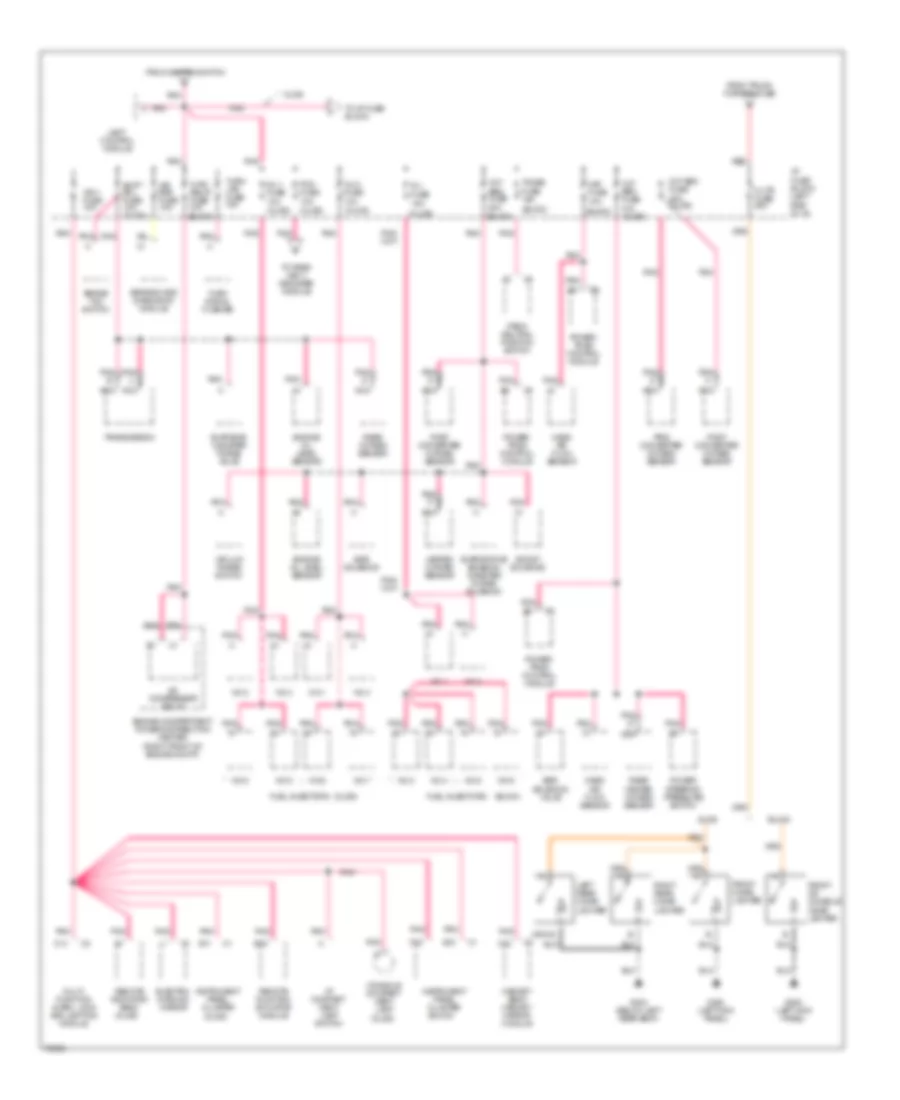
Power Distribution Wiring Diagram (2 of 4) for Oldsmobile Aurora 1996
List of elements for Power Distribution Wiring Diagram (2 of 4) for Oldsmobile Aurora 1996:
- (buick)
- (olds)
- 15a
- 20a
- Batt ther fuse 10a
- Battery thermistor
- Blower control module
- Bose amplifier/sub-woofer
- Bose fuse (olds) 20a
- Buick
- Control module
- D15
- Data link connector
- Defog rr fuse 60a
- Defogger system
- Defogger system (outside mirrors)
- Driver information center
- E14
- E16
- Elc fuse 20a
- Elc-i/p fuse 60a
- Electronic level control compressor
- Electronic level control height sensor
- Electronic level control relay
- Engine compartment power distribution center (right front of engine compt)
- Exterior lighting fuse 60a
- F/dr rel fuse 20a
- F14
- From a ign 3 fuse
- Fuel door release switch
- Fuse 40a
- Haz/ stop lps fuse 20a
- Hazard flasher
- Hdlp circuit breaker 20a
- Heated seats fuse 20a
- High speed cooling fan relay
- Hot o/s mir fuse 10a
- Hvac blower mtr fuse 30a
- Hvac pr0- grammer
- I/p fuse 10a
- Instrument cluster
- Int lp fuse 20a
- Ipc remote indi- cator bank
- Lamp
- Lamp control module
- Left front door lock relay
- Left front seat belt solenoid
- Left front seat switch
- Left front seat/ lock switch
- Left heated seat control module
- Left rear power distribution center (left rear of pass compt)
- Left rear power distribution center (left rear of vehicle)
- Left rear power distribution center (left side of pass compt)
- Low speed cooling fan relay
- Memory mirror switch
- Memory seat/ mirror module
- Multi- function alarm, lock and lighting module
- Nca
- Olds
- Outside mirror control switch
- Park lamp fuse 25a
- Passkey decoder module
- Pcm/ vats fuse 20a
- Powertrain control module
- Pwr dr locks fuse 15a
- Pwr seats fuse 50a
- Pwr st circuit breaker 25a
- Radio
- Rear compartment lid release relay
- Rear defog lower zone relay
- Rear defog upper zone relay
- Red
- Remote cd player
- Remote function actuator module
- Right front seat belt solenoid
- Right front seat switch
- Right front seat/ lock switch
- Right heated seat control module
- Right rear power distri- bution center
- Right rear power distribution center (below rear seat)
- Rr defog 1 fuse 30a
- Rr defog 2 fuse 30a
- Series/ parallel cooling fan relay
- Stop lamp/ brake switch
- To c/ltr fuse
- To retained accessory power relay
- Trunk rel fuse 15a (buick)
- Trunk/fuel dr rel
Power Distribution Wiring Diagram (3 of 4) for Oldsmobile Aurora 1996
List of elements for Power Distribution Wiring Diagram (3 of 4) for Oldsmobile Aurora 1996:
- (buick)
- (olds)
- A/c compressor relay
- Air bag fuse 10a
- B11
- Boost solenoid
- Brake/ tcc switch
- Buick
- C/ltr fuse 25a
- C12
- C13
- Console compart- ment lamp
- Control module
- E15
- Egr solenoid
- Egr solenoid valve
- Electro- chromic mirror
- Engine compartment power distribution center (right front of engine compt)
- Engine oil level sensor
- Evap emis canister purge valve
- Evaporative emission canister purge solenoid
- F15
- From ignition switch
- From trunk f/dr rel fuse
- Front cigar lighter
- Front or console cigar lighter
- Fuel injectors
- G200 (left kick panel)
- G304 (below left rear seat)
- Heated oxygen sensor
- Hvac relay fuse 10a (buick)
- I/p compart- ment lamp switch
- I/p fuse block (left side of i/p)
- Ign 1 fuse 10a
- Inj 1 fuse 10a
- Inj 2 fuse 10a
- Inj fuse 15a
- Instrument panel cluster
- Lamp
- Left rear cigar lighter
- Maf fuse 10a
- Mass air flow sensor
- Memory seat/ memory mirror module
- Multi- function alarm, lock and lighting module
- Nca
- No.1
- No.2
- No.3
- No.4
- No.5
- No.6
- No.7
- No.8
- Olds
- Oxy sen fuse 10a (olds)
- Oxy sen fuse 20a (buick)
- Oxy sen fuse 20a (olds)
- Park/ neutral position switch
- Pcm fuse 10a
- Pnk
- Post converter oxygen sensor
- Power steering pressure switch
- Power- train control module
- Pre converter oxygen sensor
- Rear heated oxygen sensor
- Rear oxygen sensor
- Red
- Remote function actuator module
- Remote indicator bank
- Right rear cigar lighter
- Sensing and diagnostic module
- Shift sol fuse 10a (olds)
- Tmnss fuse 15a
- To i/p fuse block
- To pass- key ii decoder module
- Transmission
- Turn lps fuse 15a
- Turn signal flasher
- Vacuum purge switch
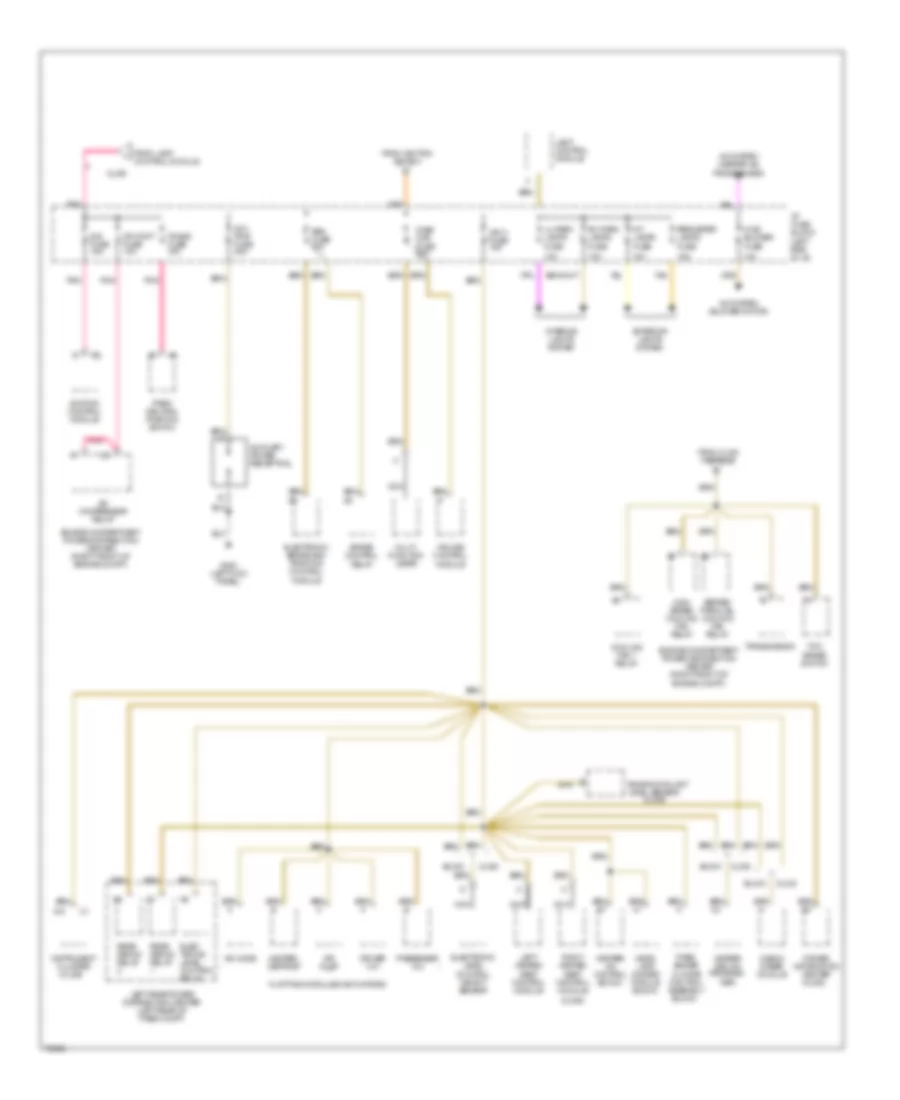
Power Distribution Wiring Diagram (4 of 4) for Oldsmobile Aurora 1996
List of elements for Power Distribution Wiring Diagram (4 of 4) for Oldsmobile Aurora 1996:
- (olds)
- 10a
- 15a
- A/c compressor relay
- A/c mode
- A/c system (blower motor)
- A/c system (heater a/c programmer)
- A10
- Abs fuse 10a
- Air inlet
- Aux pwr fuse 20a
- Auxiliary power receptical
- Brake control
- Buick
- Cooling fan 1 relay
- Cr cont fuse 10a
- Cruise control
- Dis fuse 15a
- Driver information center (olds)
- Driver mix
- Elec- tronic level control relay
- Electronic brake and traction control module
- Electronic level control height sensor
- Engine compartment power distribution center (right front of engine compt)
- Engine coolant level sensor
- Exterior lights system
- Flat pack modules (actuators)
- From clng fan fuse
- From ignition switch
- From lamp control module
- G200 (left kick panel)
- Head- lamp dimmer module (buick)
- Heater and a/c program- mer
- Heater- defrost
- Heater/ a/c control (buick)
- High speed cooling fan relay
- Hvac blower fuse
- I/p fuse block (left side of i/p)
- Ign 3 fuse 15a
- Ignition control module
- Instrument cluster
- Int lamps fuse
- Interior lights system
- Lamp control module
- Left heated seat control module
- Left rear power distribution center (left rear of pass compt)
- Lh park lamps fuse
- Magna steer module
- Module
- Multi- function lever
- Nca
- Olds
- Park/ neutral position switch
- Pass- enger climate control assembly (buick)
- Passenger mix
- Perimeter lamps fuse
- Pnk
- Rear defog relay
- Relay
- Rh park lamps fuse
- Right heated seat control module
- Series/ parallel cooling fan relay
- Step mtr fuse 20a
- Tan
- Tcc/ brake switch
- Tmnss fuse 15a
- Transmission
POWER DOOR LOCKS
Power Door Lock Wiring Diagram for Oldsmobile Aurora 1996
List of elements for Power Door Lock Wiring Diagram for Oldsmobile Aurora 1996:
- (below left rear seat)
- (w/ keyless entry only)
- A tan
- Anti- theft system
- Anti-theft system
- B/u lp fuse 15a
- Bat
- Bat c2
- Block
- C 1995 vftc
- C13
- Chime fuse 10a
- Chime module sig
- Data link connector (dlc) (left side of i/p)
- Delayed accy relay
- Door lock in
- Door lock out
- Door open in
- Door switches
- Door unlock in
- Door unlock out
- Dr lock cylinder sw
- Dr lock relay feed
- Dr lock relay out
- Dr lock switch out
- E10
- E11
- E12
- E13
- E14
- E15
- E16
- Exterior lights system
- F/dr rel fuse 20a
- F10
- F11
- F12
- F13
- F14
- F15
- F16
- G200 (left kick panel)
- G203 (right kick panel)
- G304
- G304 (below left rear seat)
- Ground
- Headlamp alarm output
- Horn relay output
- Hot at all times
- Hot in accy, or run
- Hot in run or start
- Hot in run, and during rap
- I/p 1 fuse 10a
- I/p fuse block
- Ign
- Ign 1 fuse 10a
- Intr lp fuse 15a
- Key reminder sw sig
- Left front door lock motor
- Left front door lock/ seat switch
- Left front door switch
- Left frt dr switch
- Left isolation relay
- Left rear door lock motor
- Left rear door switch
- Lock
- Luggage compartment lid release actuator (center rear of trunk lid) (w/ keyless entry only)
- Luggage compartment lid release relay
- Mem seat/mirror module
- Memory systems
- Multi-function alarm, light & locking (mall) module (behind left side of i/p)
- Park/ neutral position switch (left side of transaxle)
- Perimeter lighting relay
- Pnk
- Pnp switch
- Pwr dr lk fuse 20a
- Rear fuse
- Rear relay center (left rear of passenger compartment)
- Remote function actuator (rfab) module (under rear package shelf)
- Retained accessory power relay
- Right front door lock motor
- Right front door lock/ seat switch
- Right front door switch
- Right rear door lock motor
- Right rear door switch
- Rke program enable sig
- Security indicator
- Serial data signal
- Solid state
- Tamper switch signal
- Tan
- Trunk release relay
- Trunk release system
- Unlock
- W/ automatic door locks
- Warning system
- Wsw fuse 25a
POWER MIRRORS
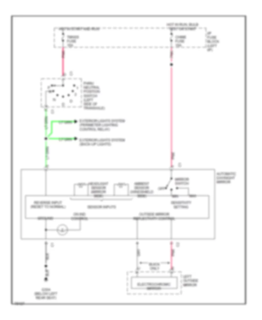
Photochromic Mirror Wiring Diagram for Oldsmobile Aurora 1996
List of elements for Photochromic Mirror Wiring Diagram for Oldsmobile Aurora 1996:
- Ambient sensor (windshield side)
- Automatic day/night mirror
- Buick only
- Chime fuse 10a
- Electrochromic
- Exterior lights system (back-up lights)
- Exterior lights system (perimeter lighting control relay)
- G304 (below left rear seat)
- Ground
- Headlight sensor (mirror side)
- Hot in run, bulb test or start
- Hot in start and run
- I/p fuse block (left i/p)
- Left outside mirror
- Max
- Min
- Mirror
- Mirror switch
- Off
- On ind control
- Outside mirror reflectivity control
- P r
- Park/ neutral position switch (left side of transaxle)
- Pnk
- Reverse input (reset to normal)
- Sensitivity setting
- Sensor inputs
- Tmnss fuse 15a
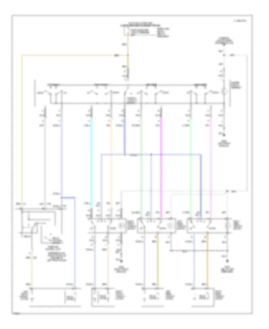
POWER SEATS
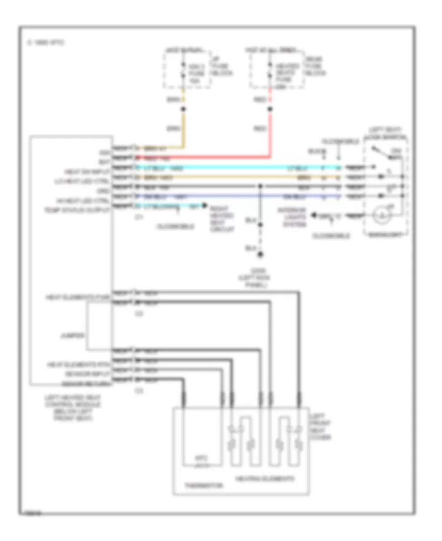
Driver Heated Seat Wiring Diagram for Oldsmobile Aurora 1996
List of elements for Driver Heated Seat Wiring Diagram for Oldsmobile Aurora 1996:
- (left kick
- 1995 vftc c
- Backlight
- Buick
- G200
- Heated seats fuse 20a
- Heating elements
- Hot at all times
- Hot in run
- I/p fuse block
- Ign 3 fuse 10a
- Interior lights system
- Jumper
- Left front seat cover
- Left heated seat control module (below left front seat)
- Left seat/ lock switch
- Nca
- Nca heat elements pwr nca
- Nca heat elements rtn nca sensor input nca senor return
- Nca ign nca bat nca heat sw input nca lo heat led ctrl nca grd nca hi heat led ctrl nca temp status output
- Ntc
- Oldsmobile
- On/ off
- Panel)
- Rear fuse block
- Red
- Right heated seat circuit
- Thermistor
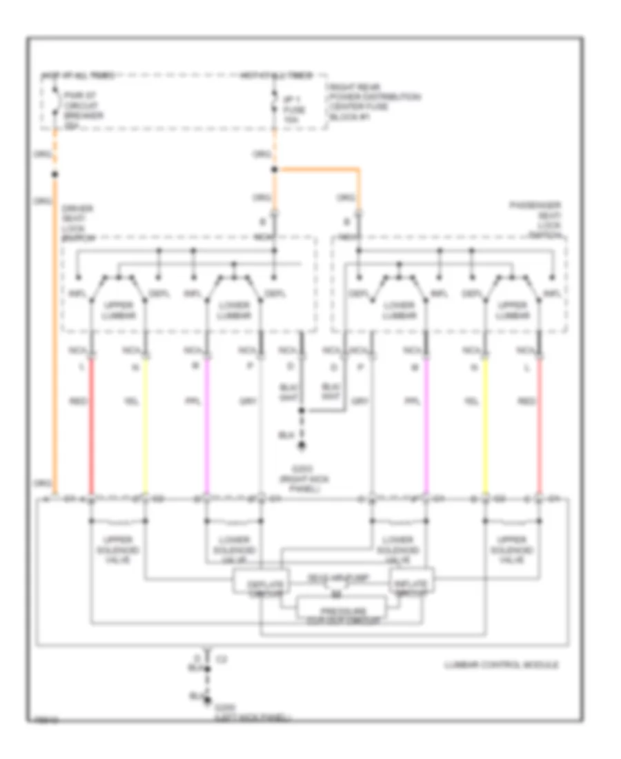
Lumbar Wiring Diagram for Oldsmobile Aurora 1996
List of elements for Lumbar Wiring Diagram for Oldsmobile Aurora 1996:
- Defl
- Deflate circuit
- Driver seat/ lock switch
- G200 (left kick panel)
- G203 (right kick panel)
- Hot at all times
- I/p 1 fuse 10a
- Infl
- Inflate circuit
- Lower lumbar
- Lower solenoid valve
- Lumbar control module
- Nca
- Passenger seat/ lock switch
- Pressure cut-out circuit
- Pwr st circuit breaker 25a
- Red
- Right rear power distribution center fuse block #1
- Seat air pump
- Upper lumbar
- Upper solenoid valve
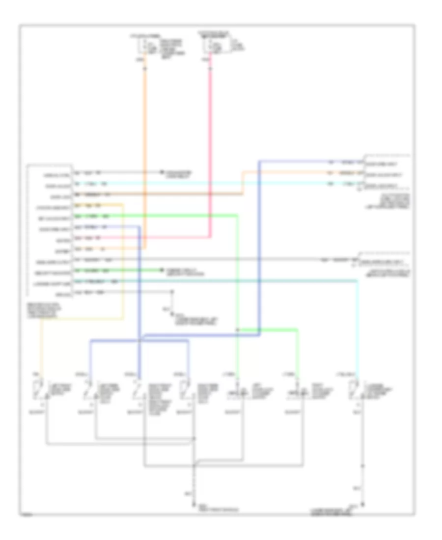
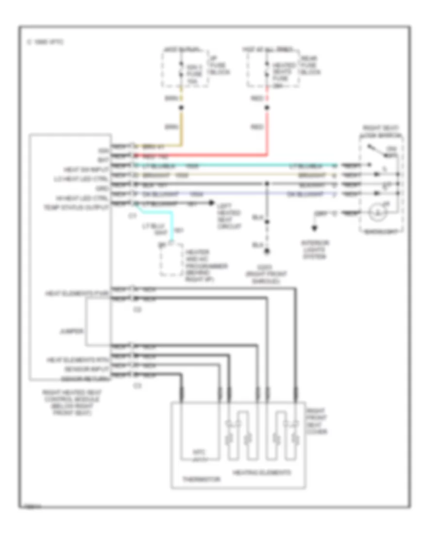
Passenger Heated Seat Wiring Diagram for Oldsmobile Aurora 1996
List of elements for Passenger Heated Seat Wiring Diagram for Oldsmobile Aurora 1996:
- (right front
- 1995 vftc c
- Backlight
- G203
- Heated seats fuse 20a
- Heater and a/c programmer (behind right i/p)
- Heating elements
- Hot at all times
- Hot in run
- I/p fuse block
- Ign 3 fuse 10a
- Interior
- Jumper
- Left heated seat circuit
- Lights system
- Nca
- Nca heat elements pwr nca
- Nca heat elements rtn nca sensor input nca senor return
- Nca ign nca bat nca heat sw input nca lo heat led ctrl nca grd nca hi heat led ctrl nca temp status output
- Ntc
- On/ off
- Rear fuse block
- Red
- Right front seat cover
- Right heated seat control module (below right front seat)
- Right seat/ lock switch
- Shroud)
- Thermistor
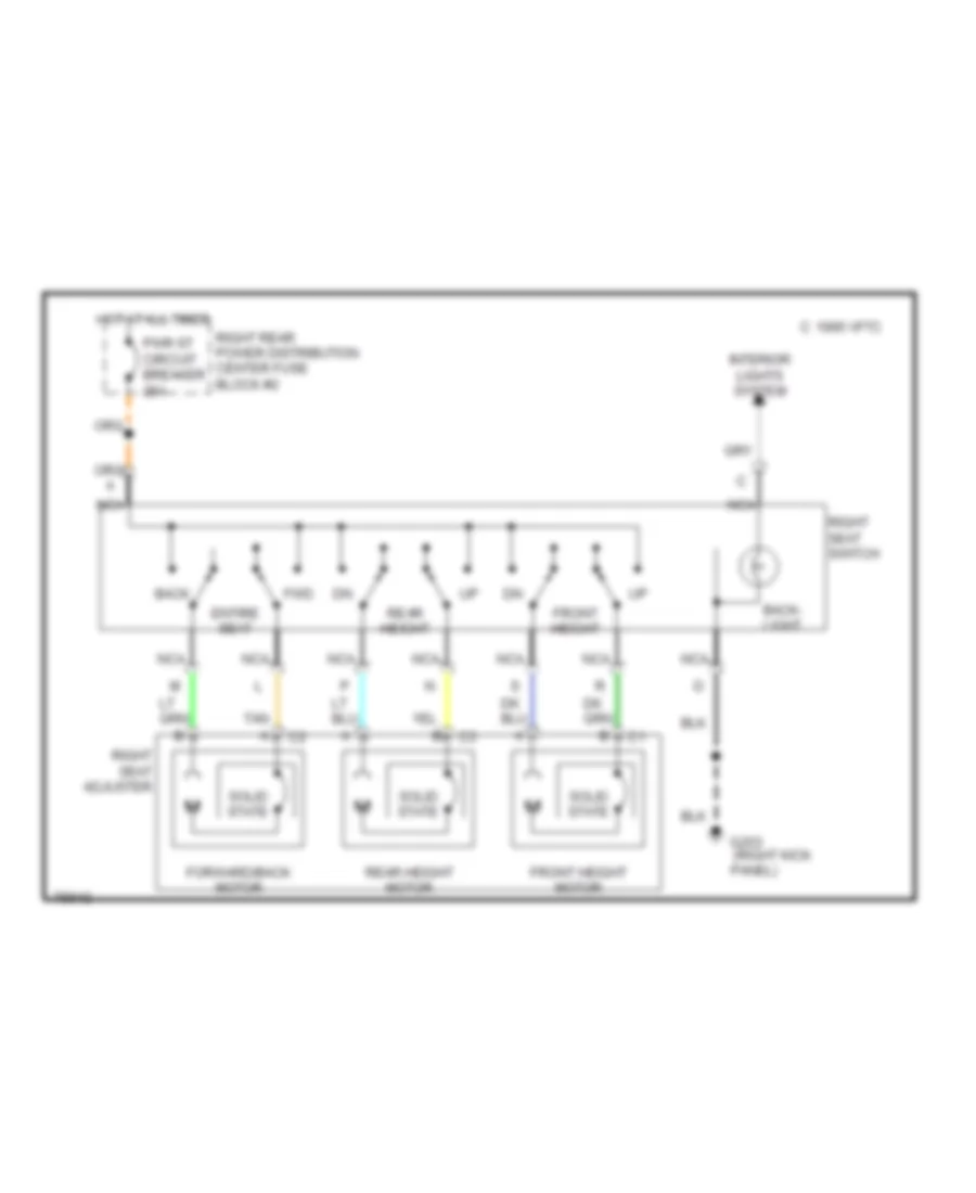
Passenger Power Seat Wiring Diagram for Oldsmobile Aurora 1996
List of elements for Passenger Power Seat Wiring Diagram for Oldsmobile Aurora 1996:
- (right kick
- 1995 vftc c
- Back
- Back- light
- Entire seat
- Forward/back motor
- Front height
- Front height motor
- Fwd
- G203
- Hot at all times
- Interior lights system
- Nca
- Panel)
- Pwr st circuit breaker 25a
- Rear height
- Rear height motor
- Right rear power distribution center fuse block #2
- Right seat adjuster
- Right seat switch
- Solid state
- Tan
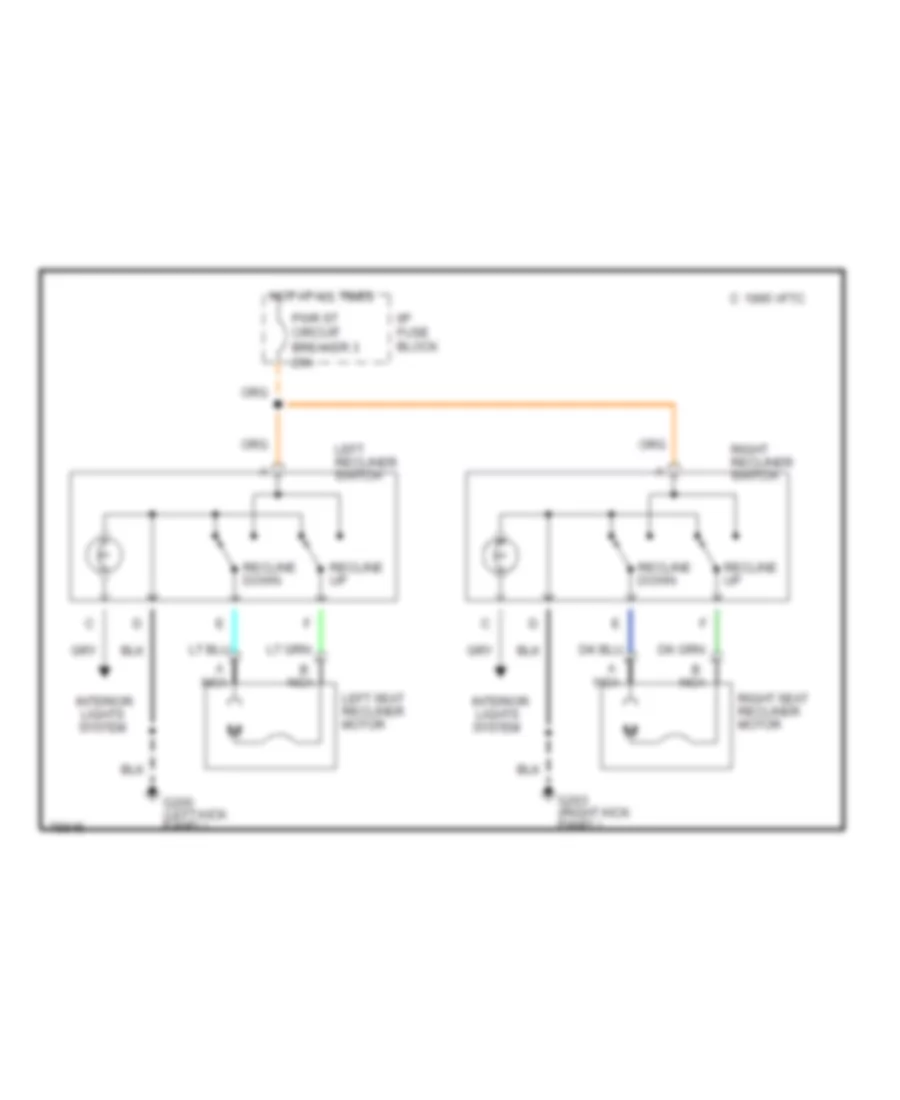
Recliner Wiring Diagram for Oldsmobile Aurora 1996
List of elements for Recliner Wiring Diagram for Oldsmobile Aurora 1996:
- 1995 vftc c
- A nca
- B nca
- G200 (left kick panel)
- G203 (right kick panel)
- Hot at all times
- I/p fuse block
- Interior lights system
- Left recliner switch
- Left seat recliner motor
- Pwr st circuit breaker 3 25a
- Recline down
- Recline up
- Right recliner switch
- Right seat recliner motor
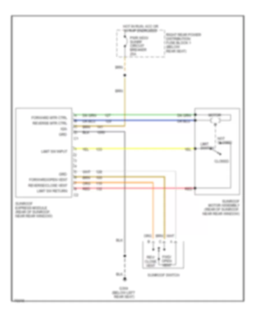
POWER TOP/SUNROOF
Sunroof Wiring Diagram for Oldsmobile Aurora 1996
List of elements for Sunroof Wiring Diagram for Oldsmobile Aurora 1996:
- (below left
- Closed
- Forward mtr ctrl
- Forward/open vent
- Fwd/ open vent
- G304
- Grd
- Hot in run, acc or w/ rap energized
- Ign
- Limit sw input
- Limit sw return
- Limit switch
- Motor
- Not closed
- Pwr wdo/ sunrf circuit breaker 25a
- Rear seat)
- Red
- Rev/ close vent
- Reverse mtr ctrl
- Reverse/close vent
- Right rear power distribution fuse block 1 (below rear seat)
- Sunroof express module (rear of sunroof, near rear window)
- Sunroof motor assembly (rear of sunroof, near rear window)
- Sunroof switch
POWER WINDOWS
Power Window Wiring Diagram for Oldsmobile Aurora 1996
List of elements for Power Window Wiring Diagram for Oldsmobile Aurora 1996:
- C 1995 vftc
- Down
- Express down window module (center of left front door)
- G200 (left front shroud)
- G203 (right front shroud)
- G304 (below left rear seat)
- Hot in run, start and during retained accessory power
- Interior lights system (dimmer module)
- Left front
- Left front window motor
- Left rear
- Left rear window motor
- Left rear window switch
- Master switch assembly
- Nca
- Pwr wdo/sunrf circuit breaker 25a
- Rear fuse block (below rear seat)
- Relay
- Relay control switch
- Right front
- Right front window motor
- Right front window switch
- Right rear
- Right rear window motor
- Right rear window switch
- Solid state
- Tan
- Timer and control unit
- Window lockout switch
RADIO
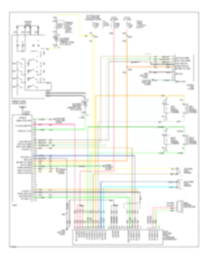
Radio Wiring Diagrams, with Bose System for Oldsmobile Aurora 1996
List of elements for Radio Wiring Diagrams, with Bose System for Oldsmobile Aurora 1996:
- 14v switched pwr
- A10
- A11
- A12
- Antenna
- Antenna enable
- Audio amplifier (bose) (under rear package shelf)
- Audio return
- B10
- B11
- B12
- Battery
- Battery voltage
- Bose fuse 20a
- Coaxial cable
- Compact disc player
- Computer data lines system
- Display dimming
- E10
- E11
- E12
- E13
- E14
- E15
- E16
- F10
- F11
- F12
- F13
- F14
- F15
- F16
- G200 (left kick panel)
- Ground
- Hot at all times
- Hot in run, acc or w/ retained accessory power
- I/p fuse block
- Ign voltage
- Inflatable restraint steering wheel coil module
- Interior lights system
- Ip2 fuse 10a
- Left audio feed
- Left front speaker (tweeter)
- Left front speaker (woofer)
- Left rear door speaker
- Lf audio (+)
- Lf spkr (+)
- Lf spkr (-)
- Lr audio (+)
- Lr spkr (+)
- Lr spkr (-)
- Nca
- Pnk
- Power antenna system
- Radio
- Radio fuse 10a
- Rear speaker (sub-woofer)
- Red
- Ref voltage
- Rf audio (+)
- Rf spkr (+)
- Rf spkr (-)
- Right audio feed
- Right front speaker (tweeter)
- Right front speaker (woofer)
- Right rear door speaker
- Right rear junction block
- Rr audio (+)
- Rr spkr (+)
- Rr spkr (-)
- S228
- S232
- S233
- S236
- S237
- S246
- Serial data
- Serial data uart
- Shield ground
- Steering column fuse holder (1998 & 99 only)
- Steering wheel control switch
- Strg whl ctlr
- Sw1
- Sw2
- Sw3
- Sw4
- Sw5
- Sw6
- Sw7
- Sw8
- Switch fuse 2a
- Tan
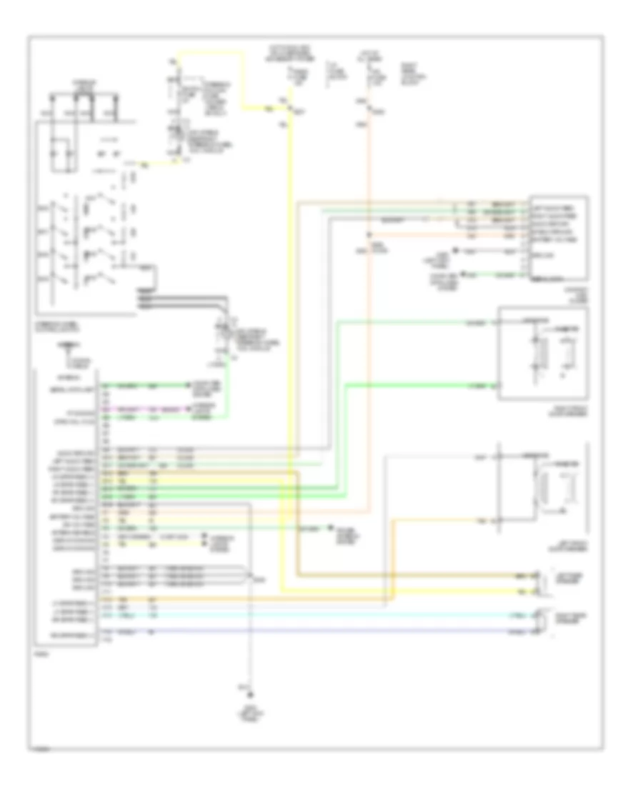
Radio Wiring Diagrams, without Bose System for Oldsmobile Aurora 1996
List of elements for Radio Wiring Diagrams, without Bose System for Oldsmobile Aurora 1996:
- (1998, 99 buick)
- (buick)
- (olds)
- 8 (or 1244)
- Antenna
- Antenna enable
- Audio return
- Battery voltage
- Coaxial cable
- Compact disc player
- Computer data lines system
- Display dimming
- E10
- E11
- E12
- E13
- E14
- E15
- E16
- F10
- F11
- F12
- F13
- F14
- F15
- F16
- G200 (left kick panel)
- Ground
- Hot at all times
- Hot in run, acc or w/ retained accessory power
- I/p fuse block
- Ign voltage
- Inflatable restraint steering wheel coil module
- Interior lights system
- Ip2 fuse 10a
- Left audio feed
- Left front door speaker
- Left rear speaker
- Lf spkr feed (+)
- Lf spkr feed (-)
- Lr spkr feed (+)
- Lr spkr feed (-)
- Midrange
- Nca
- Power antenna system
- Radio
- Radio fuse 10a
- Rf spkr feed (+)
- Rf spkr feed (-)
- Right audio feed
- Right front door speaker
- Right rear junction block
- Right rear speaker
- Rr spkr feed (+)
- Rr spkr feed (-)
- S228
- S237
- S246
- Serial data
- Serial data uart
- Shield ground
- Steering column fuse holder (1998 & 99 only)
- Steering wheel control switch
- Strg whl ctlr
- Sw1
- Sw2
- Sw3
- Sw4
- Sw5
- Sw6
- Sw7
- Sw8
- Switch fuse 2a
- Tan
- Tweeter
- Vf dimming
SHIFT INTERLOCKS
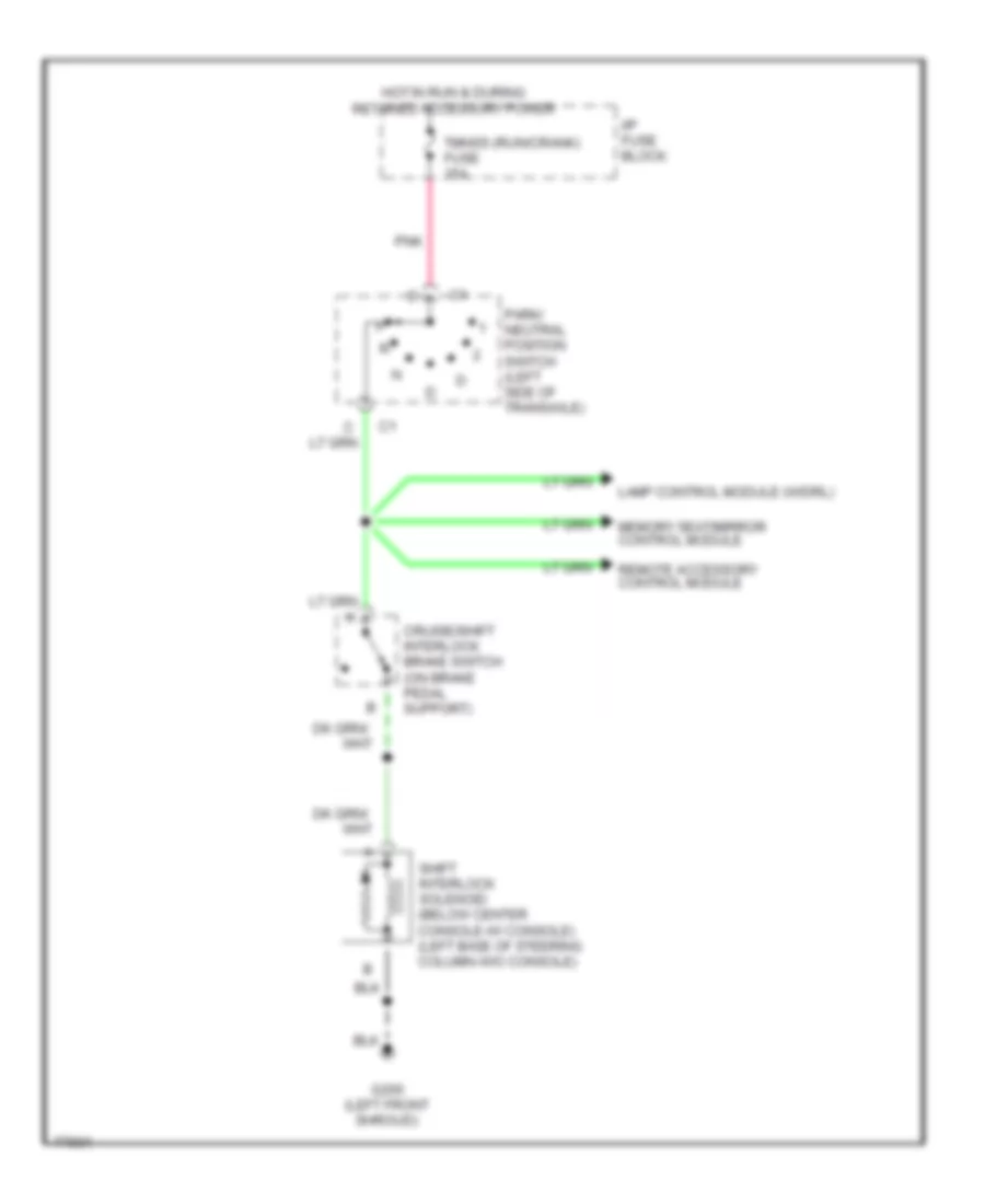
Shift Interlock Wiring Diagram for Oldsmobile Aurora 1996
List of elements for Shift Interlock Wiring Diagram for Oldsmobile Aurora 1996:
- Cruise/shift interlock brake switch (on brake pedal support)
- G200 (left front shroud)
- Hot in run & during retained accessory power
- I/p fuse block
- Lamp control module (w/drl)
- Memory seat/mirror control module
- Park/ neutral position switch (left side of transaxle)
- Pnk
- Remote accessory control module
- Shift interlock solenoid (below center console-w/ console) (left base of steering column-w/o console)
- Tmnss (run/crank) fuse 15a
STARTING/CHARGING
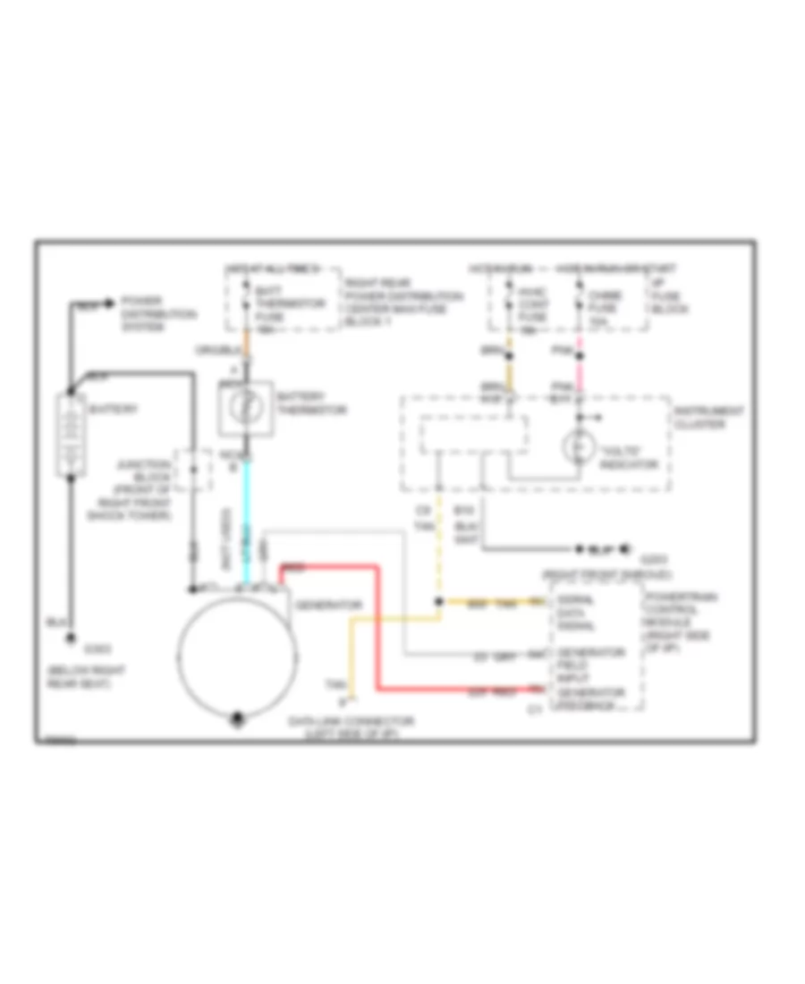
Charging Wiring Diagram for Oldsmobile Aurora 1996
List of elements for Charging Wiring Diagram for Oldsmobile Aurora 1996:
- "volts" indicator
- (below right rear seat)
- (not used) p
- (right front shroud)
- B10
- Batt thermistor fuse 10a
- Battery
- Battery thermistor
- Chime fuse 10a
- Data link connector (left side of i/p)
- G203
- G303
- Generator
- Generator feedback
- Generator field input
- Hot at all times
- Hot in run
- Hot in run or start
- Hvac cont fuse 10a
- I/p fuse block
- Instrument cluster
- Junction block (front of right front shock tower)
- Nca
- Nca b
- Pnk
- Pnk b11
- Power distribution system
- Powertrain control module (right side of i/p)
- Red
- Right rear power distribution center maxi fuse block 1
- Serial data signal
- Tan
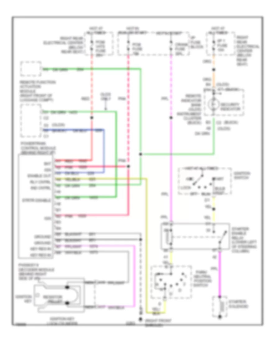
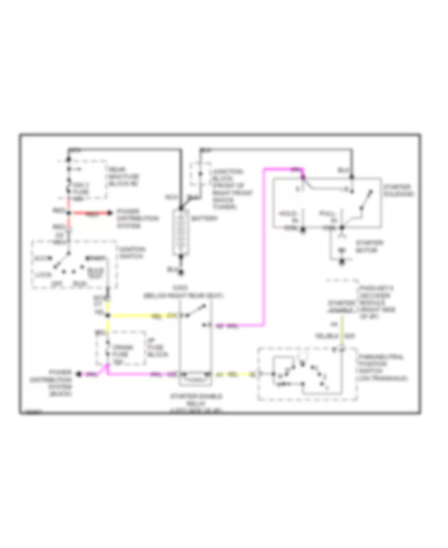
Starting Wiring Diagram for Oldsmobile Aurora 1996
List of elements for Starting Wiring Diagram for Oldsmobile Aurora 1996:
- (below right rear seat)
- Accy
- Battery
- Bulb test
- Crank fuse 10a
- D5 nca
- G303
- Hold- in coil
- I/p fuse block
- Ign 3 fuse 60a
- Ignition switch
- Junction block (front of right front shock tower)
- Lock
- Nca
- Nca d1
- Off
- Park/neutral position switch (on transaxle)
- Pass-key ii decoder module (right side of i/p)
- Power distribution system
- Power distribution system (buick)
- Pull- in coil
- Rear maxi fuse block #2
- Red
- Run
- Start
- Starter enable
- Starter enable relay (left side of i/p)
- Starter motor
- Starter solenoid
SUPPLEMENTAL RESTRAINTS
Supplemental Restraint Wiring Diagram for Oldsmobile Aurora 1996
List of elements for Supplemental Restraint Wiring Diagram for Oldsmobile Aurora 1996:
- (buick)
- (center of steering wheel)
- (olds) (buick)
- (right i/p)
- (right of
- A1 e15
- A9 e3
- Air bag fuse 10a
- Air bag warning indicator
- B nca
- Bar
- Body control module (above right i/p insulator panel)
- Data line
- Data link connector
- Driver
- F15
- Forward sdm sensor (center front of vehicle, forward of radiator)
- G200 (left kick panel)
- G300 (below left front seat)
- Ground
- Hot in run or start
- I/p fuse block
- Ign 1
- Ign-1 fuse 10a
- Ind lamp feed
- Infl feed driv
- Infl feed pass
- Infl out driv
- Infl out pass
- Inflator module
- Instrument cluster
- Nca
- Passenger inflator module
- Pnk
- Remote indicator bank (olds)
- Seat belt sig
- Seat belt switch
- Sensing and diagnostic module (above right sound insulator)
- Shorting
- Shorting bar
- Sir coil assembly
- Steering column)
- Tan
TRANSMISSION
4.0L
4.0L (VIN C), Transmission Wiring Diagram for Oldsmobile Aurora 1996
List of elements for 4.0L (VIN C), Transmission Wiring Diagram for Oldsmobile Aurora 1996:
- (all)
- (engine harn, approx 10 cm from conn near thermostat housing)
- (left side of transaxle) park/neutral position switch
- (under left side of dash) data link connector
- 1-2 shift sol
- 1996-
- 1998-
- 2-3 shift sol
- 5v reference
- A/t fluid pressure manual valve position switch
- A/t input speed hi in
- A/t input speed lo in
- A/t iss sensor
- Anti-theft system
- Automatic transaxle (4t80-e)
- Battery in
- Brake switch in
- Chime fuse 10a
- Cruise control
- Cruise control system
- Cruise engaged in
- Data class ii
- Ect sensor in
- Engine controls
- Engine coolant temperature sensor (top left side of engine)
- Evap control solenoid
- Evap vent valve (1998-99)
- Front heated oxygen sensor
- G119 (right front of engine)
- G200 (behind left kick panel)
- Hot at all times
- Hot in run or start
- Hot in run, bulb test or start
- I/p fuse block
- Ignition in
- Lamp control module, instrument cluster, body contol module. rear view mirror, memory seat/ mirror module
- Malfunction indicator lamp
- Mil control
- Passkey decoder module & instrument cluster
- Pcm fuse 10a
- Pcm ground
- Pcm/vats fuse 20a
- Pcs sol hi
- Pcs sol lo
- Pnk
- Pnp switch in
- Powertrain control module (behind right side of dash)
- Pressure control sol
- Rear maxi-fuse block 2
- Red
- Remote indicator bank
- S114
- S118
- S123 (engine harn, 5 cm from oil press switch break-out)
- S127 (partial) (engine harness, left front of engine)
- S241
- S245 (body main harn, 38 cm from pcm)
- S248
- S258
- S294 (1998- 99) pnk
- S297
- S316 (1998-99)
- S317 (1996-97)
- Sensor return
- Serial data
- Shift select in
- Shift select switch
- Shift sol fuse 10a
- Tan
- Tcc anti- lock brake switch (behind left side of dash)
- Tcc pwm sol
- Tft sensor
- Tft sensor hi in
- Throttle position sensor (throttle body)
- Tp sensor in
- Trans range "a"
- Trans range "b"
- Trans range "c"
- Vehicle speed sensor (lower right rear of engine compt, on transaxle)
- Vss hi in
- Vss lo in
TRUNK, TAILGATE, FUEL DOOR
Trunk & Fuel Door Release Wiring Diagram for Oldsmobile Aurora 1996
List of elements for Trunk & Fuel Door Release Wiring Diagram for Oldsmobile Aurora 1996:
- F/dr rel fuse 20a
- Fuel door
- Fuel door release solenoid (left quarter panel, at fuel door)
- G200 (under left kick panel trim)
- G304 (under rear seat, near door lock relay)
- Hot at all times
- Interior lights system
- Left rear pdc, relay block #3 (left rear of passenger compartment)
- Lugg compt
- Luggage compart- ment lid release relay
- Luggage compartment lid release actuator (center rear of luggage compt lid, near latch)
- Luggage compartment lid/fuel door release switch assembly
- Motor m
- Pnk
- Ptc
- Relay control
- Remote function actuator (rfa) module (under rear package shelf)
- Right rear pdc, fuse block #1 (left rear of passenger compartment, under rear seat)
- Valet switch
WARNING SYSTEMS
Warning System Wiring Diagrams for Oldsmobile Aurora 1996
List of elements for Warning System Wiring Diagrams for Oldsmobile Aurora 1996:
- (buick only)
- (left kick panel)
- (olds only)
- (right kick panel)
- * olds ** buick
- 13**
- 25*
- A12*
- A6*
- A9*
- B6*
- Brake warn indic in
- Buick
- C1**
- C10
- C11
- C12
- C13
- C14
- C15
- C16
- C2*
- Chime ctrl in
- Chime ctrl out
- Courtesy lamps (batt)
- Courtesy lamps out
- Cruise control system
- D10
- D11
- D12
- D13
- D14
- D15
- D16
- D2*
- Door locks system
- Door open input
- E12
- Electronic power steering system
- Exterior lights system
- F3**
- Fasten belts indicator
- G200
- G200 (left kick panel)
- G203
- G203 (right kick panel)
- Ground
- Hot at all times
- Hot in run or start
- Hot in run or start i/p fuse block
- Ign 1 fuse 10a
- Ignition key warning switch (inside steering column assy)
- Instrument cluster system
- Instrument panel cluster
- Int lp fuse 20a
- Interior lamp rly ctrl
- Interior lamps ctrl in
- Interior lights system
- Key-in input
- Key-in output
- Key-in-ignition sw in
- Lamp control module (behind left kick panel)
- Left front door switch (buick only)
- Left front door switch (olds only)
- Left rear door switch (olds only)
- Lft frt door sw in
- Lft turn signal in
- Multi-function alarm, lock and lighting (mall) module (left kick panel, next to lamp control module)
- Nca
- Olds
- Park brake in
- Park lamp sw in
- Pnk
- Power (battery)
- Power (ignition)
- Powertrain control module (behind right side of i/p)
- Pwr door lck-lock
- Pwr door lck-unlock
- Pwr door lock-lock
- Pwr door lock-unlock
- Pwr dr lk fuse 15a (buick) 20a (olds)
- Remote function actuator module (below right side of parcel shelf)
- Right front door switch (buick only)
- Right front door switch (olds only)
- Right rear door switch (olds only)
- Right rear power distribution center fuse block #1 (under rear seat, on right side)
- Rt door sw in
- Rt turn signal in
- Safety belt switch (seat belt buckle assy)
- Seat belt indic out
- Seat belt sw in
- Tan
- Turn flasher (behind left side of i/p)
- Turn lamps fuse 15a
- Turn signal in
- Vss in
- Vss out
WIPER/WASHER
Wiper/Washer Wiring Diagram for Oldsmobile Aurora 1996
List of elements for Wiper/Washer Wiring Diagram for Oldsmobile Aurora 1996:
- (right side of engine compartment)
- 1.2 m
- 24k
- Circuit breaker
- Cover assembly
- G103
- High speed input
- Hot in acc or run
- I/p fuse block
- Latch arm
- Low
- Mist
- Nca
- Off
- Park switch
- Pnk
- Pulse
- Red
- S115
- S292
- Solid state timer
- Speed input
- Washer motor
- Washer switch
- Wiper motor
- Wiper motor module
- Wiper switch
- Wiper washer switch
- Wsw fuse 25a