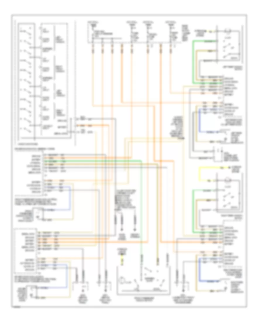
AIR CONDITIONING
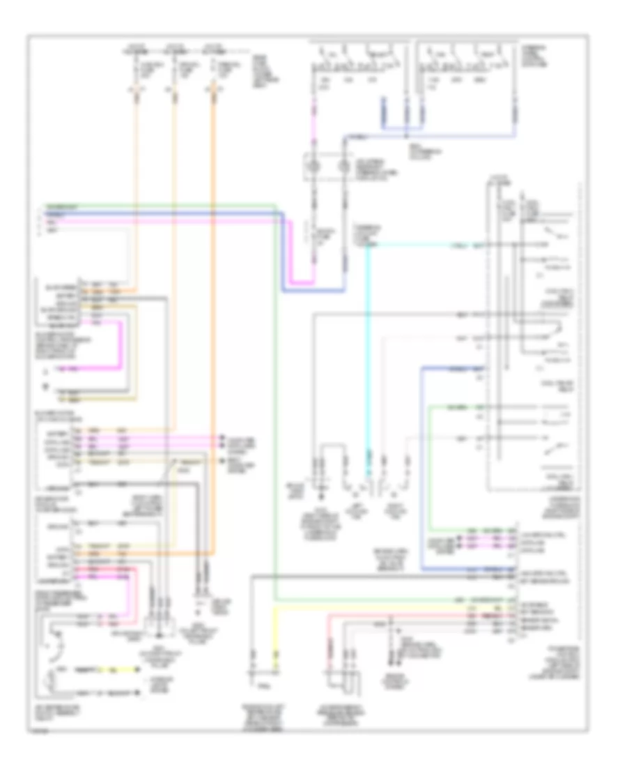
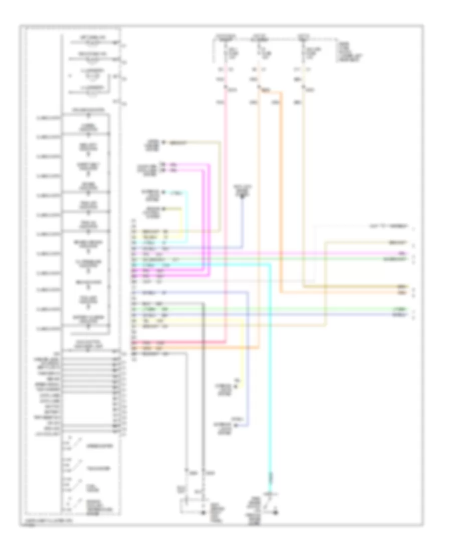
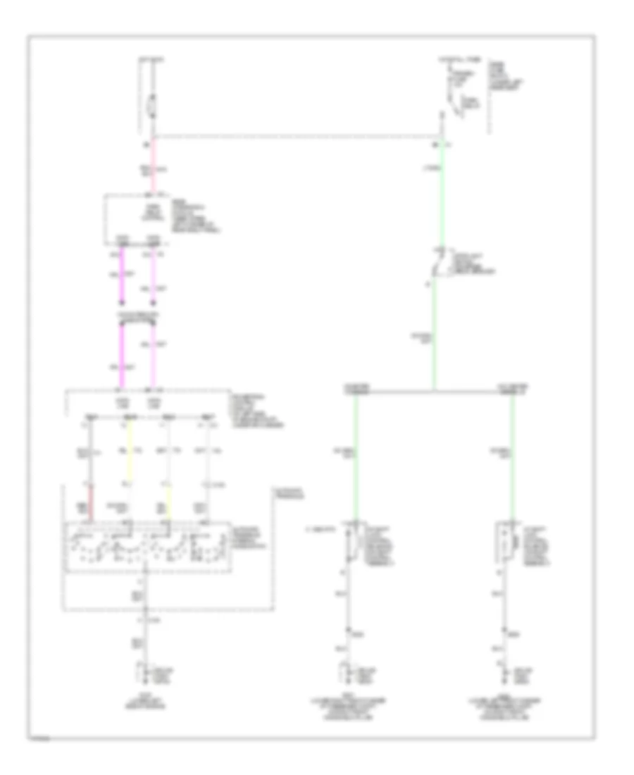
Automatic A/C Wiring Diagram (1 of 2) for Oldsmobile Aurora 2003

List of elements for Automatic A/C Wiring Diagram (1 of 2) for Oldsmobile Aurora 2003:
- (behind right side of dash) dash integration module (dim)
- (center of dash, behind hvac controls) instrument panel integration module (ipm)
- (hvac harn, 23.5 cm from c204 break- out) s222
- (hvac harn, 30 cm from c204 break- out)
- (hvac harn, 36.5 cm from c204 break- out) s220
- (i/p harn, 18 cm from c201 breakout)
- (i/p harn, 31 cm from c201 breakout)
- (on left front
- 5v ref feed
- A/c clu fuse 15a
- A/c clu relay
- A/c compressor clutch
- A/c orifice solenoid
- A/c refrigerant low temperature sensor
- A/c temperature sensor (ambient) (front center of engine compt)
- A10
- A11
- A12
- Air mix act cntl
- Air mix act sig
- Air temperature
- Air temperature actuator (left) (top left side of hvac housing)
- Air temperature actuator (right) (top right side of hvac housing)
- Air temperature sensor (lower right) (right air discharge vent)
- Air temperature sensor (upper left) (left air discharge vent)
- Air temperature sensor (upper right) (right air discharge vent)
- Amb air temp sig
- Amb light sens
- Battery
- Blower speed ctrl
- C1 a10
- C1 c11
- C12
- C13
- C3 d12
- C3 e11
- Computer data lines system
- Cr cont fuse 10a
- D11
- D16
- Data line
- Dim fuse 10a
- G100 (lower left side of engine)
- G103 (right side of engine compt)
- G200
- G201 (lower
- Ground
- Hot at all times
- Hot in on
- Hvac (b+) fuse 10a
- Hvac control module (center of dash, above radio)
- Hvac fuse 10a
- Hvac sig
- Hvac sol relay
- Ign 3 rr fuse 10a
- Ign sw fuse 15a
- Ignition
- Illum
- In air temp sig
- Inside air temp sensor (right side of steering column)
- Interior lights system
- Lh sun load sens
- Ll air temp sig
- Lr air temp sig
- Mode act cntl
- Mode actuator (top of hvac housing)
- Mode dr pos sens
- Motor ground
- Nca
- Rear fuse block (under left rear seat)
- Recirc act cntl
- Recirc act sig
- Recirculation actuator (right front of blower motor assy)
- Rh sun load sens
- Right "a" pillar)
- S204
- S205 (dash harn, right side of dash)
- S209
- S221
- Sensor (lower left) (left air discharge vent)
- Sensor grd
- Solid state
- Splice pack sp100
- Splice pack sp103
- Splice pack sp201
- Steer whl feed
- Steer whl rtn
- Sunload sensor assembly (top center of dash)
- Tan
- Ul air temp sig
- Underhood fuse block (right side of engine compt)
- Ur air temp sig
- Windshield pillar)
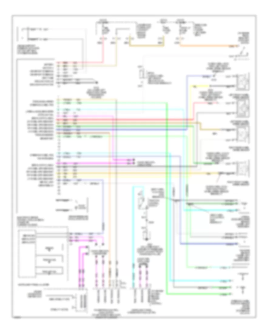
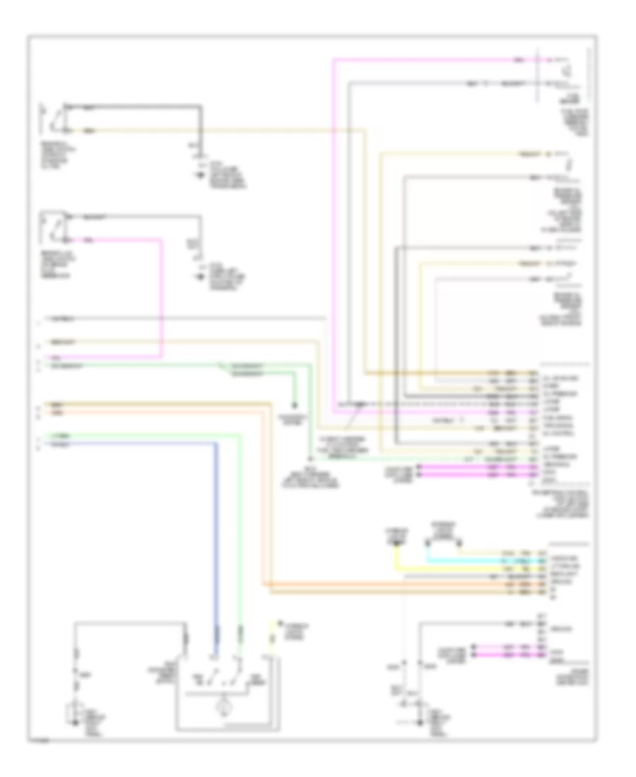
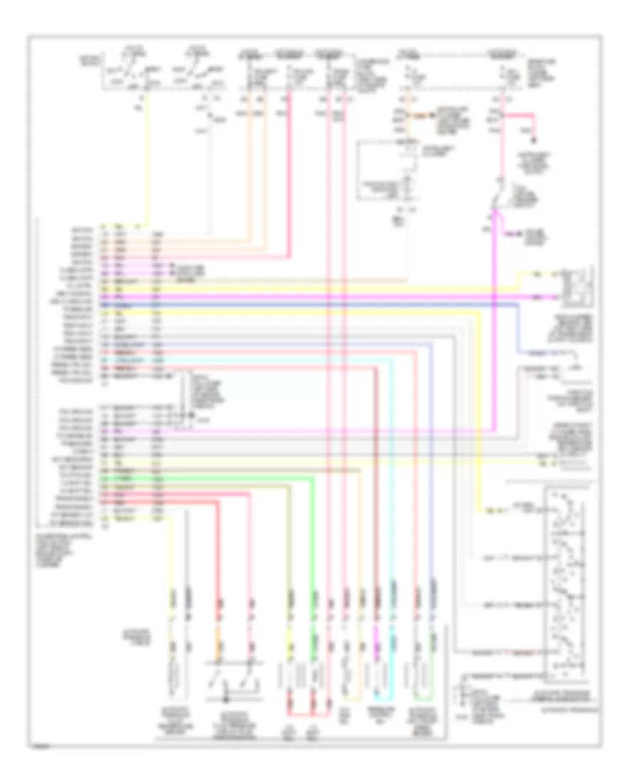
Automatic A/C Wiring Diagram (2 of 2) for Oldsmobile Aurora 2003
List of elements for Automatic A/C Wiring Diagram (2 of 2) for Oldsmobile Aurora 2003:
- (body harn, 14.5 cm from left power seat breakout)
- (engine harn, 6.5 cm from iac valve breakout)
- 5 v
- A/c enable
- A/c refrigerant pressure sensor (behind a/c compressor)
- Air temperature switch assembly (right)
- B10
- Battery
- Blower motor (on hvac housing)
- Blower motor control processor (behind dash, at right front of blower motor)
- Blwr ground
- Blwr speed
- Blwr volt
- Body computer system
- C1 a1
- C3 a7
- Computer data lines system
- Cool fan 1 fuse 30a
- Cool fan 1 relay (low speed)
- Cool fan 2 fuse 30a
- Cool fan 2 relay (high speed)
- Cool fan s/p relay
- D10
- Data
- Data line
- Driver door module (in driver door)
- Drv mdl fuse 10a
- E nca
- E10
- Ect sens sig
- Ect sense ground
- Engine controls system
- Engine coolant temperature (ect) sensor (rear of right cylinder head)
- F11
- Fan
- Front passenger door module (fpdm) (in passenger door)
- G nca
- G103 (right side of engine compt, in front of the underhood fuse block)
- G200 (on left front windshield pillar)
- G201 (on right front windshield pillar)
- Ground
- High spd fan ctrl
- Hot at all times
- Hvac blo fuse 30a
- Inflatable restraint steering wheel module coil
- Interior lights system
- Left cooling fan
- Low spd fan ctrl
- Nca
- Pass mdl fuse 10a
- Pnk
- Powertrain control module (pcm) (left side of engine compt, under air cleaner)
- Rear fuse block (under left rear seat)
- Right cooling fan
- S105 (engine harn, 9.5 cm from pcm c1 connector)
- S106
- S224 (in steering column)
- S302
- Select
- Sensor grd
- Sensor signal
- Speed ctrl
- Splice pack sp103
- Splice pack sp200
- Splice pack sp201
- Steering column fuse holder
- Steering wheel control switches
- Sw return
- Switch fuse 2a
- Temp
- Underhood fuse block (right side of engine compt)
- Vol
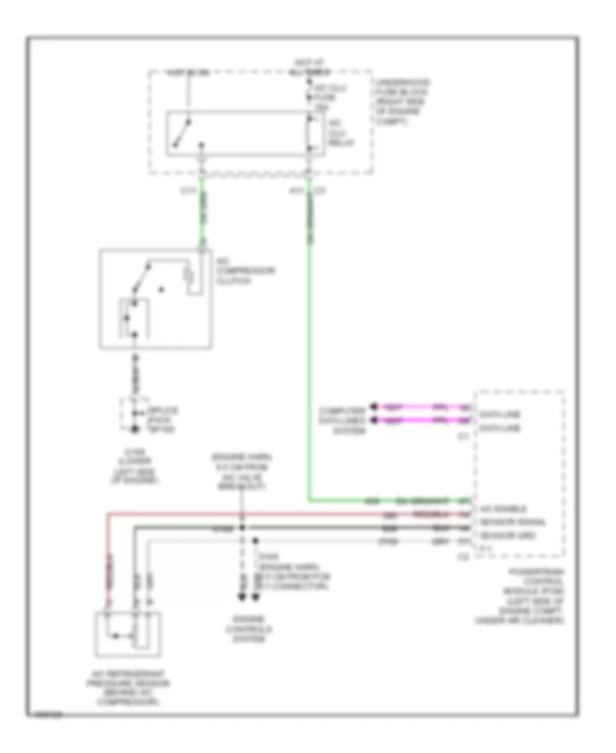
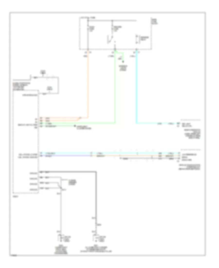
Compressor Wiring Diagram for Oldsmobile Aurora 2003
List of elements for Compressor Wiring Diagram for Oldsmobile Aurora 2003:
- (engine harn, 6.5 cm from iac valve breakout)
- 5 v
- A/c clu fuse 15a
- A/c clu relay
- A/c compressor clutch
- A/c enable
- A/c refrigerant pressure sensor (behind a/c compressor)
- Computer data lines system
- Data line
- Engine controls system
- G100 (lower
- Hot at all times
- Hot in on
- Left side of engine)
- Powertrain control module (pcm) (left side of engine compt, under air cleaner)
- S106
- Sensor grd
- Sensor signal
- Splice pack sp100
- Underhood fuse block (right side of engine compt)
ANTI-LOCK BRAKES
Anti-lock Brakes Wiring Diagram for Oldsmobile Aurora 2003
List of elements for Anti-lock Brakes Wiring Diagram for Oldsmobile Aurora 2003:
- (at center of dash, behind heater & a/c control)
- (body harn, 18 cm from g300 breakout)
- (body harn, 31.5 cm from g300 breakout)
- (in eng harn, 12.5 cm from right front wheel speed sensor breakout) s101
- (in eng harn, 19 cm from right front wheel speed sensor breakout)
- (in eng harn, 49 cm from left front wheel speed sensor breakout)
- (on brake pedal bracket) stoplamp switch
- Abs fuse 10a
- Abs fuse 50a
- Abs ind
- Abs ind lamp
- Abs ind sig
- Battery
- Brake pressure modulator valve
- C1 (4.0l)
- C11
- C12
- C2 (3.5l)
- Computer data lines system
- Del torque
- Driver information center (dic)
- Electronic brake control module (ebcm) (under air cleaner housing)
- G104 (on lower left side of eng, near transmission) housing)
- G201 (on lower right corner of passenger compt, on right front windshield pillar)
- Ground-module
- Ground-pump motor
- Hot at all times
- Hot in run
- Ignition 3
- Instrument panel cluster
- Instrument panel integration module (ipm)
- Lateral accelerometer
- Lateral accelerometer sensor (under left rear seat)
- Left front wheel speed sensor
- Left rear wheel speed sensor
- Lf wheel spd sens-ret
- Lf wheel spd sens-sig
- Lr wheel spd sens-ret
- Lr wheel spd sens-sig
- Nca
- Powertrain control module (pcm) (at left side of eng comp, under air cleaner)
- Pump motor
- Rear fuse block (under left rear seat)
- Red
- Req torque
- Rf wheel spd sens-ret
- Rf wheel spd sens-sig
- Right front wheel speed sensor
- Right rear wheel speed sensor
- Rr wheel spd sens-ret
- Rr wheel spd sens-sig
- S102
- S103
- S104 (in eng harn, 42.5 cm from left front wheel speed sensor breakout)
- S228
- S303
- S305
- Sens feed-5v
- Sensor ret
- Serial data
- Serial data class 2
- Serv stability sys
- Sp304 (in body harn, left side of vehicle, 8.5 cm from g300 breakout)
- Stability active
- Steering wheel pos
- Steering wheel position sensor (swps) (at base of steering column)
- Stop lp fuse 15a
- Stoplight sw
- Tan
- Torque delivered
- Torque desired
- Trac ctl sw
- Trac off ind
- Trac on ind
- Traction control switch
- Underhood fuse block (on right side of engine compt)
- Var effort steering
- Variable effort steering actuator (on top left end of steering gear)
- Vent tube
- Yaw rate sens
- Yaw rate sensor (under left rear seat, near battery)
ANTI-THEFT
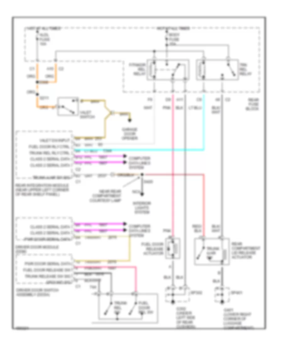
Forced Entry Wiring Diagram for Oldsmobile Aurora 2003
List of elements for Forced Entry Wiring Diagram for Oldsmobile Aurora 2003:
- A11
- A12
- B12
- C200
- Class 2 data line
- Computer data lines system
- Dash integration module (behind right side of dash)
- Door open input
- Driver door lock actuator
- Driver door lock cylinder switch
- Driver door module
- Drv mdl fuse 10a
- Exterior lights system
- Front passenger door lock actuator
- Front passenger door module
- Ground
- Horn ctrl
- Horns system
- Hot at all times
- Hot in on and off
- Ign 1 fuse 10a
- Instrument panel cluster
- Left rear door lock actuator
- Left rear door module
- Lf door key sw sig
- Lf door open in
- Lights ctrl
- Nca
- Pass mdl fuse 10a
- Pnk
- Pwr door serial data
- Rear fuse block (under left rear seat)
- Rear integration module (left corner of rear package shelf)
- Right rear door lock actuator
- Right rear door module
- Rrdr mdl fuse 10a
- S216
- S302 (body harn, near left power seat breakout)
- Security ind
- Serial data class 2
- Tan
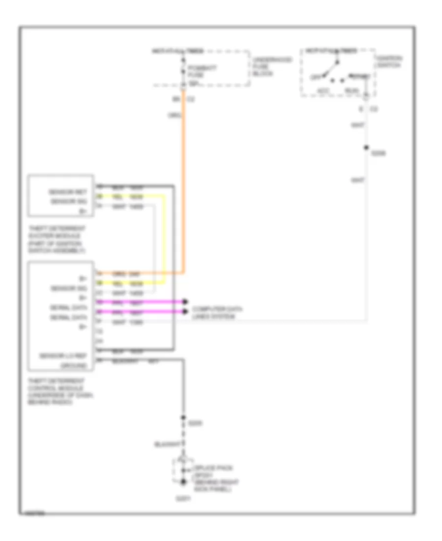
Pass-Key Wiring Diagram for Oldsmobile Aurora 2003
List of elements for Pass-Key Wiring Diagram for Oldsmobile Aurora 2003:
- (part of ignition switch assembly)
- 10a
- Acc
- B6 c2
- Computer data lines system
- E c2
- G201
- Ground
- Hot at all times
- Ignition switch
- Off
- Pcm/batt fuse
- Run
- S205
- S208
- Sensor lo ref
- Sensor ret
- Sensor sig
- Serial data
- Splice pack sp201 (behind right kick panel)
- Start
- Theft deterrent control module (underside of dash, behind radio)
- Theft deterrent exciter module
- Underhood fuse block
BODY CONTROL MODULES
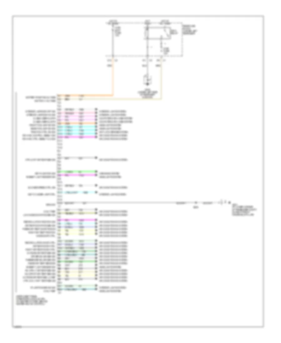
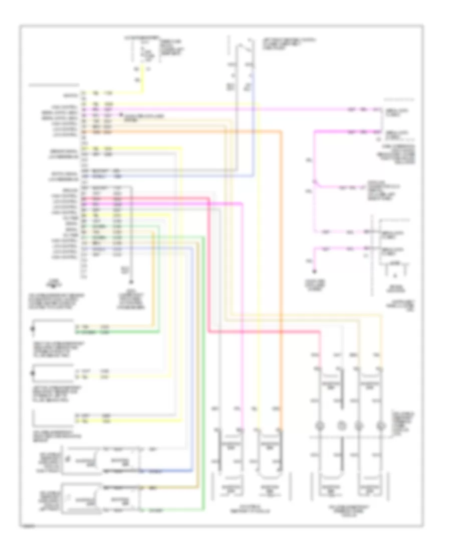
Instrument Panel Integration Module Wiring Diagram for Oldsmobile Aurora 2003
List of elements for Instrument Panel Integration Module Wiring Diagram for Oldsmobile Aurora 2003:
- 5 volt ref
- A/c upr lt air temp sen sig
- A/c upr rt air temp sen sig
- A10
- A11
- A12
- Air conditioning system
- Air temp door ctrl
- Air temp door pos sen sig
- Ambient light sensor sig
- Anti-lock brakes system
- B10
- B11
- B12
- Battery positive voltage
- Blower speed ctrl sig
- C10
- C11
- C12
- C13
- C14
- C15
- C16
- Class 2 serial data
- Computer data lines system
- D10
- D11
- D12
- D13
- D14
- D15
- D16
- Dr hvac control assbly sig
- Dr hvac ctrl assbly clk sig
- Driver solar sen sig
- Front fog lamp sw sig
- G201 (in lower corner of passenger compt, on right front windshield pillar)
- G302 (under left side of rear seat cushion)
- Ground
- Headlights system
- Hot at all times
- Hot in on
- Htr lo rt air temp sen sig
- Htr low lt s.p. temp sen sig
- Hvac batt fuse 10a
- Hvac fuse 10a
- I/p lamp dimmer sw sig
- Ign-3 relay
- Ignition 3 voltage
- Inside air temp sens sig
- Instrument panel integration module (ipm) (at center of dash, behind heater and a/c control)
- Interior lamps sw off sig
- Interior lamps sw on sig
- Interior lights system
- Key cylinder lamp ctrl
- Key in ignition sig
- Low mode door pos sen sig
- Mode door ctrl
- Outside air temp sen lo ref
- Outside air temp sen sig
- Passenger solar sen sig
- Passr air temp door pos sig
- Rear fog lamp sw sig
- Rear fuse block (under left rear seat)
- Recirculation door ctrl
- Recirculation position sig
- Right air temp door ctrl
- Right air temp position
- S205
- Tan
- Traction ctrl sw sig
- Warnings system
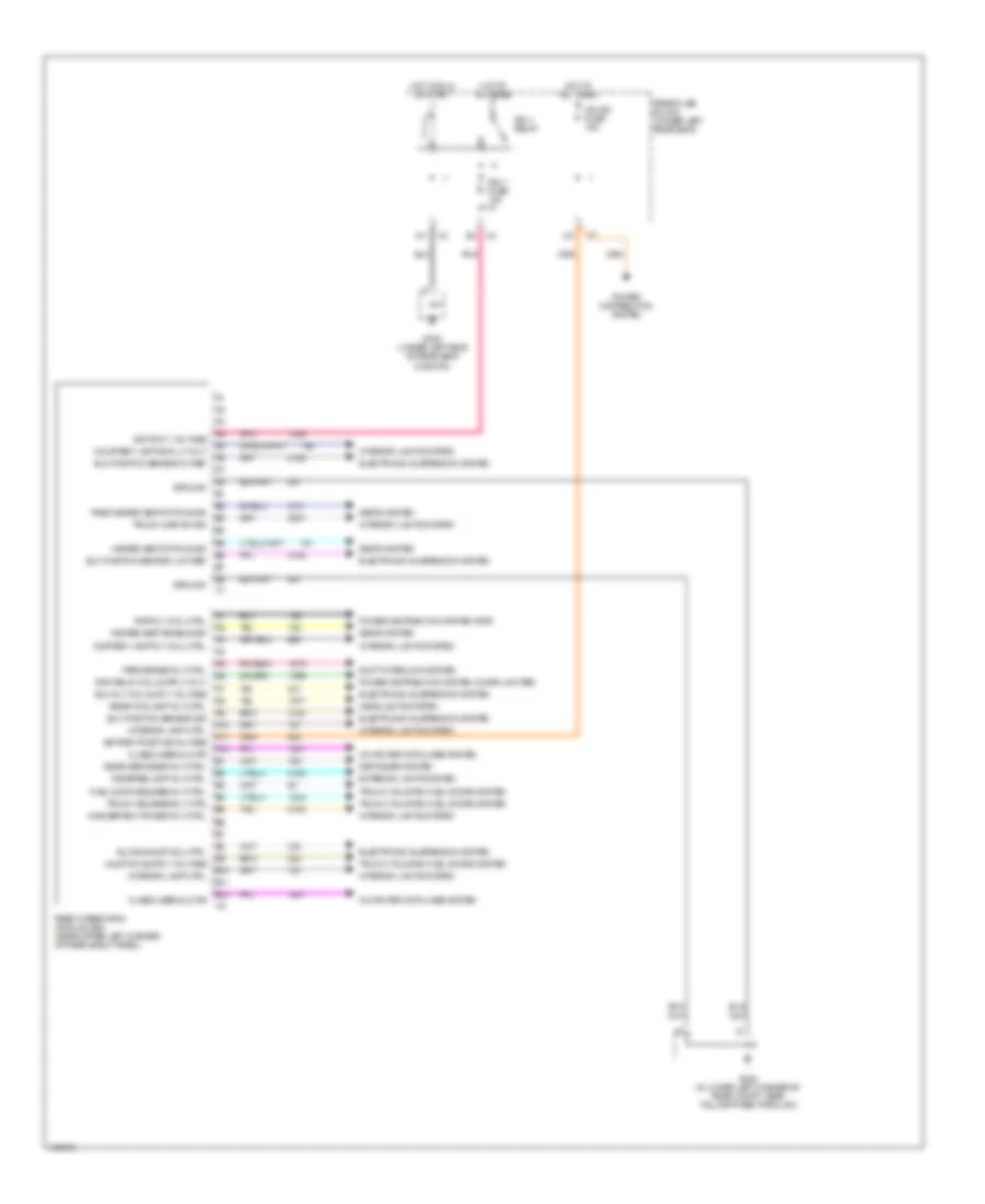
Rear Integration Module Wiring Diagram for Oldsmobile Aurora 2003
List of elements for Rear Integration Module Wiring Diagram for Oldsmobile Aurora 2003:
- A10
- A11
- A12
- B10
- B11
- B12
- B4 trunk release rly ctrl
- Battery positive voltage
- Class 2 serial data
- Computer data lines system
- Cortesy lamp rly coil ctrl
- Courtesy lamp suplly volt
- Defogger system
- Elc exhaust sol ctrl
- Elc position sensor 5v ref
- Elc position sensor low ref
- Elc position sensor sig
- Elc rly coil suply voltage
- Electronic suspension system
- Exterior lights system
- Fuel door release rly ctrl
- G302 (under left side of rear seat cushion)
- G402 (in lower left corner of rear compt, near taillamp pass-through)
- Ground
- Headlights system
- Heated seat enable sig
- Heated seat status sig
- Hot at all times
- Hot in run or start
- Ign sw fuse 15a
- Ign-1 fuse 10a
- Ign-1 relay
- Ignition 1 voltage
- Inadvertent power rly ctrl
- Interior lamp ctrl
- Interior lights system
- Park brake rly ctrl
- Pass heated seat status sig
- Pnk
- Power distribution system
- Power distribution system (cigar lighter)
- Power distribution system (rap)
- Rap rly coil ctrl
- Rear defogger rly ctrl
- Rear fog lamp rly ctrl
- Rear fuse block (under left rear seat)
- Rear integration module (rim) (near upper left corner of rear shelf panel)
- Reverse lamp rly ctrl
- Seats system
- Shift interlock system
- Tan
- Trunk ajar sw sig
- Trunk, tailgate, fuel doors system
COMPUTER DATA LINES
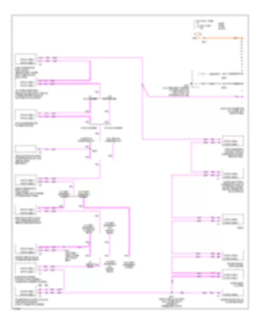
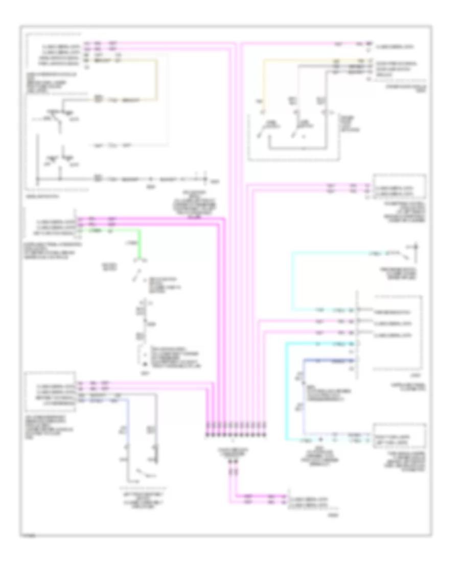
Computer Data Lines Wiring Diagram for Oldsmobile Aurora 2003
List of elements for Computer Data Lines Wiring Diagram for Oldsmobile Aurora 2003:
- 3.5l
- 4.0l
- A11
- A12
- Aldl fuse 10a
- B12
- Cd changer-remote playback device
- D14
- D15
- Dash integration module (dim) (behind dash, under right dash sound insulator)
- Data class 2
- Data link connector (at lower left side of dash)
- Driver door module (in driver door)
- Driver inform- ation center
- Electronic brake control module (ebcm) (under air cleaner housing)
- G201 (in lower right corner of pass compt, on right front of windshield pillar)
- Hot at all times
- Inflatable restraint sensing & diagnostic module (under center console, mounted to floor pan)
- Instrument cluster
- Instrument panel integration module (at center of dash, behind heater and a/c controls)
- Memory seat module (under driver's seat)
- Powertrain control module (left side of engine compt, under air cleaner)
- Radio
- Rear fuse block
- Rear intergration module (rim) (near upper left corner of rear shelf panel)
- Remote control door lock receiver (rcdlr) (behind rear seat back)
- S205
- S209
- S211
- S217 (body harn, 24 cm from left lower front corner of passenger compt)
- S317 (left seat harn, under left front seat)
- S345
- Theft deterrent control module (underside of dash, behind radio)
- Vehicle communication interface module (vcim) (behind rear seat back)
- W/ cd changer
- W/ memory seats
- W/ theft deterrent system
- W/ theft deterrent,
- W/ theft deterrent, w/ memory seats
- W/ theft deterrent, w/o memory seats
- W/ vehicle interface unit
- W/o vehicle interface unit
- W/o cd changer
- W/o memory seats
- W/o theft deterrent system
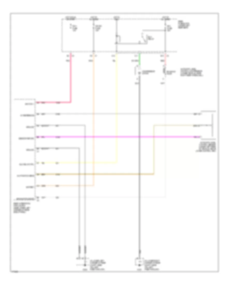
COOLING FAN
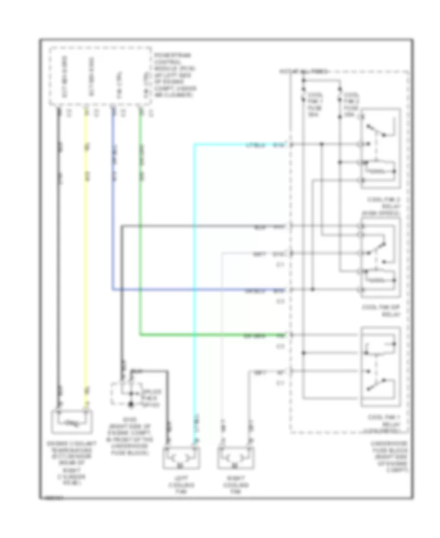
Cooling Fan Wiring Diagram for Oldsmobile Aurora 2003
List of elements for Cooling Fan Wiring Diagram for Oldsmobile Aurora 2003:
- B10
- Cool fan 1 fuse 30a
- Cool fan 1 relay (low speed)
- Cool fan 2 fuse 30a
- Cool fan 2 relay (high speed)
- Cool fan s/p relay
- D10
- E10
- Ect sens grd
- Ect sens sig
- Engine coolant temperature (ect) sensor (rear of
- F11
- Fan ctrl
- G103 (right side of engine compt, in front of the underhood fuse block)
- Hot at all times
- Left cooling fan
- Powertrain control module (pcm) (at left side of engine compt, under air cleaner)
- Right cooling fan
- Right cylinder head)
- Splice pack sp103
- Underhood fuse block (right side of engine compt)
CRUISE CONTROL
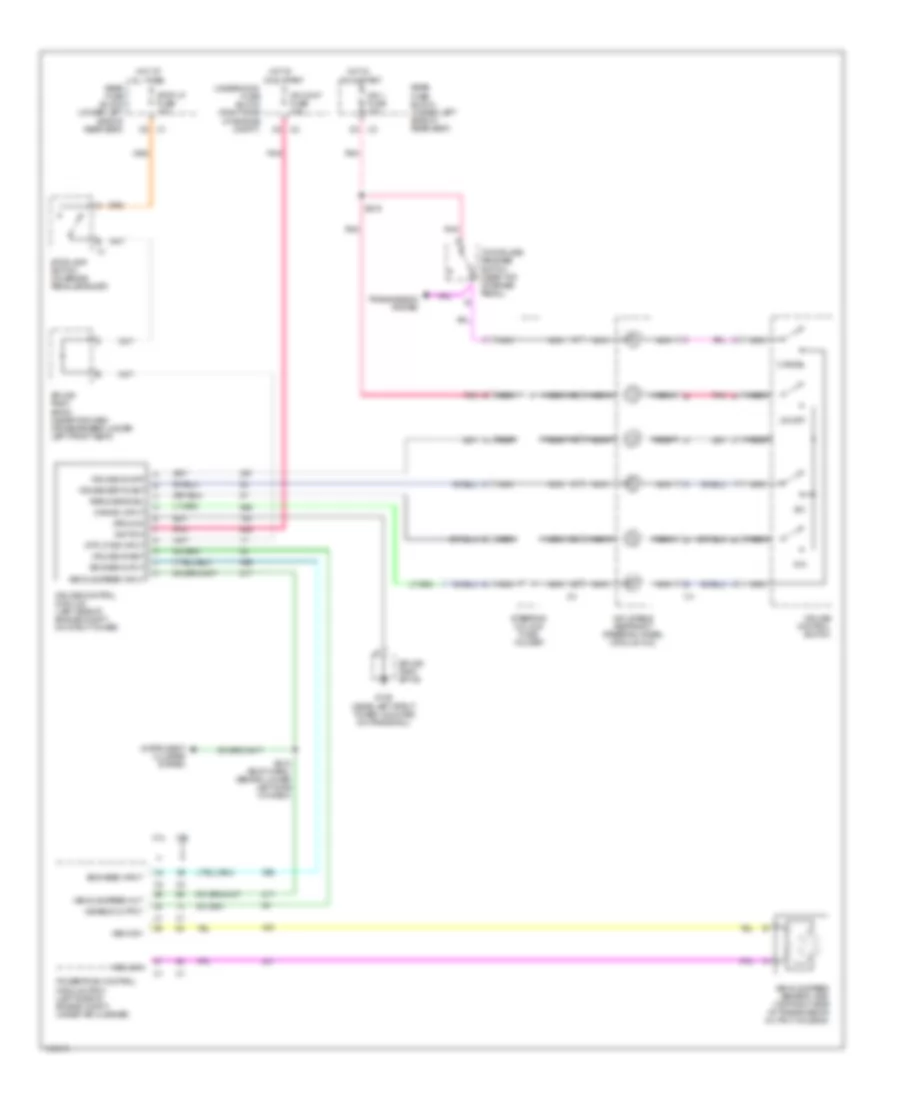
Cruise Control Wiring Diagram for Oldsmobile Aurora 2003
List of elements for Cruise Control Wiring Diagram for Oldsmobile Aurora 2003:
- 3.5l
- 4.0l
- All times
- Cancel
- Cancel input
- Cr cont fuse 10a
- Cruise control module (left side of engine compt, on strut tower)
- Cruise control switch
- Cruise inhibit
- Cruise on/off
- Cruise set/coast
- Disable output
- Engage ouput
- Engaged input
- G106 (near left strut tower, mounted on frame rail)
- Ground
- Hot at
- Hot in
- Ign 1 fuse 10a
- Ignition
- Inflatable restraint steering wheel module coil
- Instrument cluster system
- Nca
- On & start
- On/off
- Pnk
- Powertrain control module (pcm) (left side of engine compt, under air cleaner)
- R/a
- Rear fuse block (under left side of rear seat)
- Resume/accel
- S/c
- S215 (body harn, (behind lower left side of dash)
- S216
- Splice pack sp106
- Splice pack sp304 (near forward crossmember, under left front seat)
- Steering column fuse holder
- Stop lp fuse 15a
- Stoplamp switch (on brake pedal bracket)
- Stp lp sig input
- Tcc/cruise release switch (near top of brake pedal)
- Transmission system
- Underhood fuse block (right side of engine compt)
- Vehicle speed input
- Vehicle speed out
- Vehicle speed sensor (vss) (top right side of transmission output housing)
- Vss high
- Vss low
DEFOGGERS
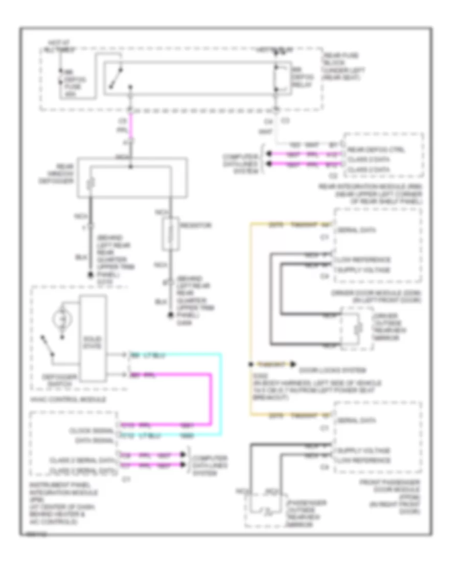
Defoggers Wiring Diagram for Oldsmobile Aurora 2003
List of elements for Defoggers Wiring Diagram for Oldsmobile Aurora 2003:
- (behind left rear rear quarter upper trim panel) g310
- (behind left rear rear quarter upper trim panel) g404
- A12
- B12
- C12
- C13
- Class 2 data
- Class 2 serial data
- Clock signal
- Computer data lines system
- Data signal
- Defogger switch
- Door locks system
- Driver door module (ddm) (in left front door)
- Driver outside rearview mirror
- Front passenger door module (fpdm) (in right front door)
- Hot at all times
- Hot in run
- Hvac control module
- Instrument panel integration module (ipm) (at center of dash, behind heater & a/c controls)
- Low reference
- Nca
- Passenger outside rearview mirror
- Rear defog ctrl
- Rear fuse block (under left rear seat)
- Rear integration module (rim) (near upper left corner of rear shelf panel)
- Rear window defogger
- Resistor
- Rr defog fuse 40a
- Rr defog relay
- S302 (in body harness, left side of vehicle 14.5 cm (5.7 in) from left power seat breakout)
- Serial data
- Solid state
ELECTRONIC POWER STEERING
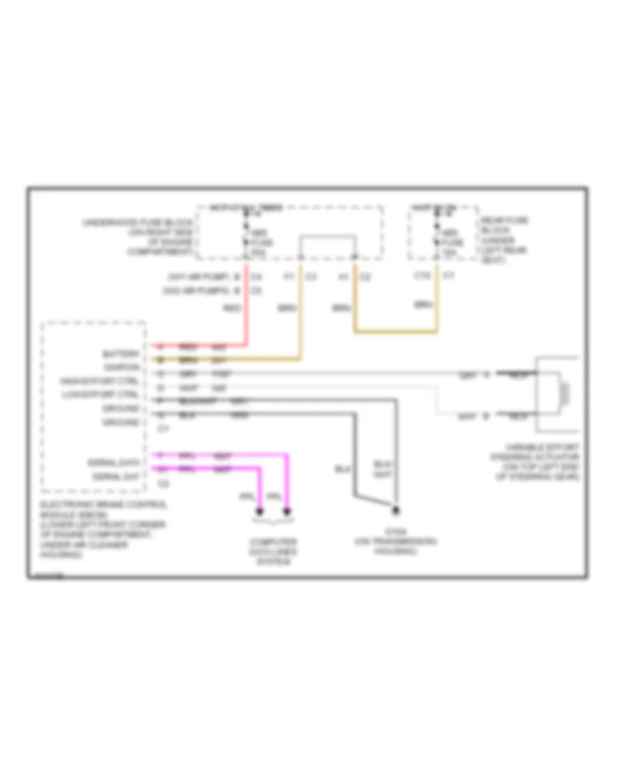
Electronic Power Steering Wiring Diagram for Oldsmobile Aurora 2003
List of elements for Electronic Power Steering Wiring Diagram for Oldsmobile Aurora 2003:
- Abs fuse 10a
- Abs fuse 50a
- B (w/1 air pump)
- B (w/2 air pumps)
- Battery
- C12
- Computer data lines system
- Electronic brake control module (ebcm) (lower left front corner of engine compartment, under air cleaner housing)
- G104 (on transmission) housing)
- Ground
- High effort ctrl
- Hot at all times
- Hot in on
- Ignition
- Low effort ctrl
- Nca
- Rear fuse block (under left rear seat)
- Red
- Serial dat
- Serial data
- Underhood fuse block (on right side of engine compartment)
- Variable effort steering actuator (on top left end of steering gear)
ELECTRONIC SUSPENSION
Electronic Suspension Wiring Diagram for Oldsmobile Aurora 2003
List of elements for Electronic Suspension Wiring Diagram for Oldsmobile Aurora 2003:
- (in lower left corner of rear compt, near taillamp pass-through)
- (in lower right corner of rear compt, near taillamp pass-through)
- 5v reference
- A11
- Alc position sens
- Automatic level control compressor (under vehicle, near right rear wheelwell)
- Automatic level control sensor (under left rear of vehicle, above lower control arm)
- B10
- Battery
- C10
- C11
- Compressor motor
- Elc fuse 30a
- Elc relay
- Elc relay ctrl
- Exhaust solenoid
- G401
- G402
- Ground
- Hot at all times
- Hot in run
- Hot in run or start
- Ign 1 fuse 10a
- Ign sw fuse 15a
- Ignition 1
- Pnk
- Rear fuse block (under left rear seat)
- Rear integration module (rim) (near upper left corner of rear shelf panel)
- Red
- Sensor return
- Solenoid valve
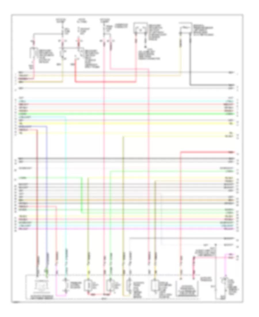
ENGINE PERFORMANCE
4.0L VIN C
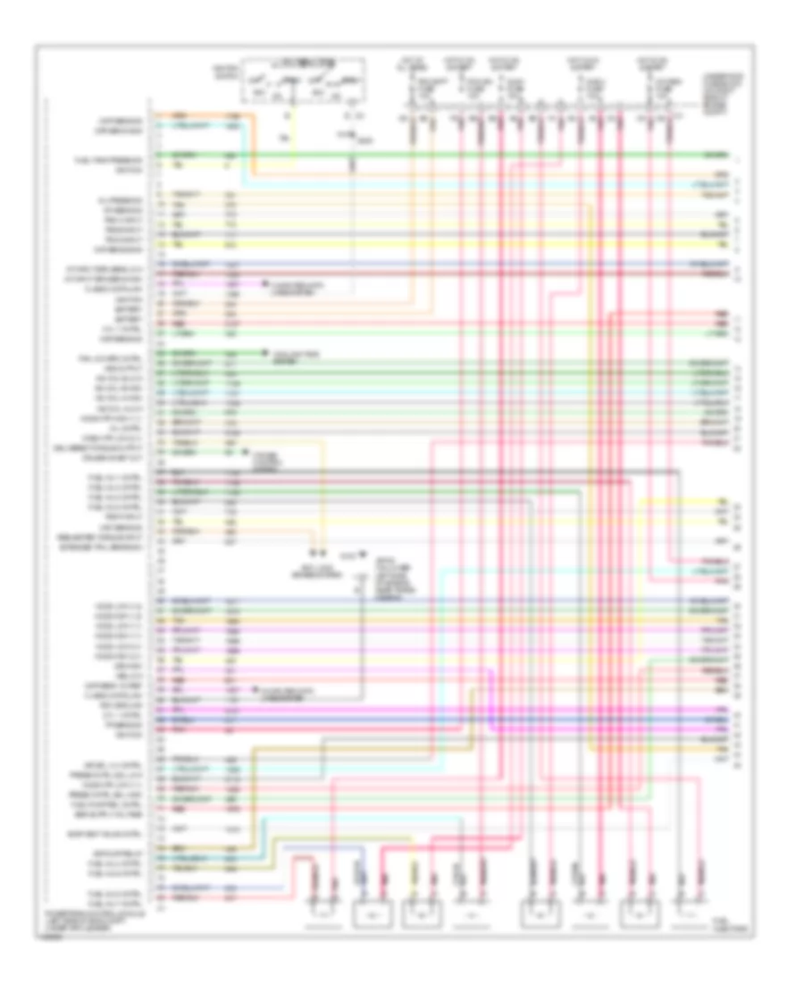
4.0L VIN C, Engine Performance Wiring Diagram (1 of 5) for Oldsmobile Aurora 2003
List of elements for 4.0L VIN C, Engine Performance Wiring Diagram (1 of 5) for Oldsmobile Aurora 2003:
- A/t input spd sens high
- A/t input spd sens low
- A6 pnk
- A8 pnk
- Acc on
- Air pump relay
- Air sol vlv cntrl
- Anti lock brakes system
- B5 pnk
- Battery
- C9 pnk
- Ckp sens a sig
- Ckp sens b sig
- Class 2 data link
- Cmp sens 12v ref
- Cmp sens sig
- Computer data lines system
- Cooling fans system
- Cruise control system
- Cruise inhibit out
- Cyl 1 cntrl
- Cyl 7 cntrl
- D4 pnk
- Delivered torque output
- E c2
- Evap vent valve cntrl
- Extended trvl brake sw
- F4 pnk
- F9 pnk
- Fan low spd cntrl
- Fuel inj 1 cntrl
- Fuel inj 2 cntrl
- Fuel inj 3 cntrl
- Fuel inj 4 cntrl
- Fuel inj 5 cntrl
- Fuel inj 6 cntrl
- Fuel inj 7 cntrl
- Fuel inj 8 cntrl
- Fuel injectors
- Fuel pump rel cntrl
- Fuel tank press sig
- G100
- Ho2s high (1,1)
- Ho2s high (1,2)
- Ho2s high (2,1)
- Ho2s htr high (1,1)
- Ho2s htr low (1,1)
- Ho2s low (1,1)
- Ho2s low (1,2)
- Ho2s low (2,1)
- Hos2 htr low (2,1)
- Hot at all times
- Hot in on & start
- Iac coil a high
- Iac coil a low
- Iac coil b high
- Iac coil b low
- Iat sens sig
- Ignition
- Ignition switch
- Injr 1 fuse 10a
- Injr 2 fuse 10a
- Maf sens sig
- Map sens sig
- Mil cntrl
- Off
- Oil press sig
- Oxy sen fuse 10a
- Pcm batt fuse 10a
- Pcm ground
- Pcm ign fuse 10a
- Pnk
- Pnk a
- Powertrain control module (left side of eng compt, under air cleaner)
- Press cntrl sol high
- Press cntrl sol low
- Red
- Requested torque input
- S208
- Sp100 (on lower left side of engine, near trans- mission)
- Start
- Tan
- Tp sens sig
- Trs a input
- Trs b input
- Trs c input
- Trs p input
- Underhood fuse block (on right side of engine compt)
- Vss high
- Vss low
- Vss output
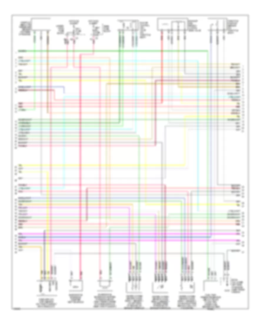
4.0L VIN C, Engine Performance Wiring Diagram (2 of 5) for Oldsmobile Aurora 2003
List of elements for 4.0L VIN C, Engine Performance Wiring Diagram (2 of 5) for Oldsmobile Aurora 2003:
- B3 pnk
- Evaporative emissions canister purge solenoid (right rear corner of intake manifold, near throttle body)
- Evaporative emissions canister vent solenoid
- Exhaust gas recirc- ulation (egr) valve
- F3 pnk
- Fuel tank pressure sensor (below trunk floor trim, under fuel sender access panel)
- G100
- Ground
- Heated oxygen sensor (ho2s) bank 1, sensor 1 (at left side of engine, on exhaust manifold)
- Heated oxygen sensor (ho2s) bank 1, sensor 2 (on exhaust pipe, behind catalytic converter)
- Heated oxygen sensor (ho2s) bank 2, sensor 1 (at right side of engine, on exhaust manifold)
- Hot in on & start
- Iat sens
- Idle air control (iac) valve (on throttle body)
- Ign
- Ign 1 fuse 10a
- Maf sens
- Manifold absolute pressure sensor (top rear of engine)
- Mass airflow (maf) sensor (on throttle body air intake duct)
- Nca
- Pnk
- Pnk d
- Rear fuse block
- Red
- Sp100 (on lower left side of engine, near trans- mission)
- Tan
- Tan a
- Throttle position sensor (on throttle body)
- Under- hood fuse block
- Vent sol fuse 10a
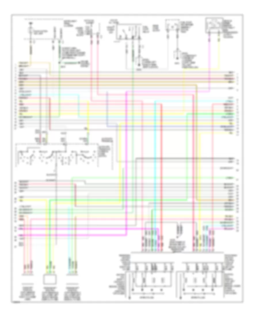
4.0L VIN C, Engine Performance Wiring Diagram (3 of 5) for Oldsmobile Aurora 2003
List of elements for 4.0L VIN C, Engine Performance Wiring Diagram (3 of 5) for Oldsmobile Aurora 2003:
- (in body harn, 19.5 cm from left lower front corner on passenger compt, on firewall)
- (right rear of engine, below engine coolant temerature sensor)
- (top right side of engine, under intake manifold top cover)
- Automatic transaxle
- Automatic transaxle internal mode switch
- Camshaft position (cmp) sensor (on front of right cylinder head)
- Coil mdl fuse 20a
- Crankshaft position (ckp) sensor a (on lower left side of engine, near oil filter)
- Crankshaft position (ckp) sensor b (on lower left side of engine, near oil filter)
- Cruise control system
- F/pmp fuse 20a
- Front bank ignition control module (top of left cam cover)
- Fuel pump and sender assembly (in fuel tank)
- Fuel pump relay
- G105
- G302
- G401
- Hot at all times
- Hot in on & start
- Ign
- Ignition coil (bank 1)
- Ignition coil (bank 2) (top left side of engine, under intake manifold top cover)
- Instrument panel cluster
- Malfunction ind lamp
- Nca
- Pnk
- Rear bank ignition control module (top of right cam cover)
- Rear fuse block
- Red
- S215
- Sp302 (under left side of rear seat cushion)
- Sp401 (lower right corner of luggage compt, near taillamp pass-through)
- Spark plugs
- Tach input
- Under- hood fuse block
- Vehicle speed sensor (top right side transmission output housing)
- Vss input
4.0L VIN C, Engine Performance Wiring Diagram (4 of 5) for Oldsmobile Aurora 2003
List of elements for 4.0L VIN C, Engine Performance Wiring Diagram (4 of 5) for Oldsmobile Aurora 2003:
- (on lower left side of engine, near trans- mission connector)
- 1-2 shift sol
- 2-3 shift sol
- A4 pnk
- Air injection (air) pump relay (w/ single pump) (near right strut tower)
- Air pump fuse 50a
- Automatic trans- axle fluid temper- ature sensor
- Automatic transaxle
- Automatic transaxle input speed sensor
- Automatic transmission
- Engine oil pressure sensor (left side of engine, near oil filter housing)
- Fluid pressure manual valve position switch
- Fuel pump and sender assembly (in fuel tank)
- G102
- Hot at all times
- Hot in on & start
- Ign 1 fuse 10a
- Pnk
- Pressure control solenoid
- Red
- S113
- S401 (in body harn, 31.5 cm from fuel tank harn breakout)
- Secondary
- Secondary air injection (air) pump (at left front of engine compt, on engine cradle)
- Secondary air injection (air) solenoid valve (on top of air pump)
- Tan
- Torque converter clutch pulse width modulation solenoid
- Trans fuse 10a
- Underhood fuse block
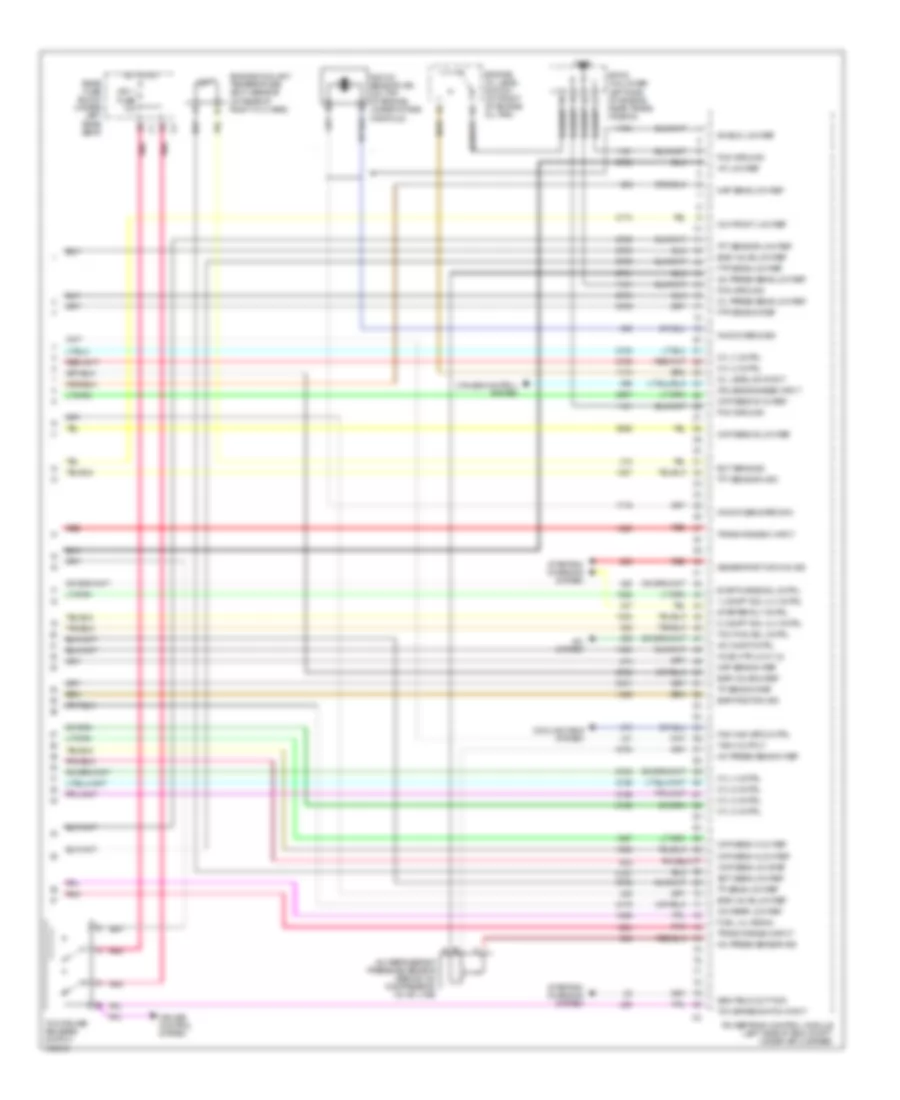
4.0L VIN C, Engine Performance Wiring Diagram (5 of 5) for Oldsmobile Aurora 2003
List of elements for 4.0L VIN C, Engine Performance Wiring Diagram (5 of 5) for Oldsmobile Aurora 2003:
- 1-2 shift sol vlv cntrl
- 2-3 shift sol vlv cntrl
- A/c comp cntrl
- A/c press sens 5v ref
- A/c press sens low ref
- A/c press sensor sig
- A/c refrigerant pressure sensor (behind a/c compressor, on a/c line)
- A/c system
- Ckp sens a 12v ref
- Ckp sens a low ref
- Ckp sens b 12v ref
- Ckp sens b low ref
- Cmp sens low ref
- Cooling fans system
- Cruise control system
- Cruise engaged input
- Cyl 2 cntrl
- Cyl 3 cntrl
- Cyl 4 cntrl
- Cyl 5 cntrl
- Cyl 6 cntrl
- Cyl 8 cntrl
- Ect sens low ref
- Ect sens sig
- Egr position sig
- Egr valve 5v ref
- Egr valve low ref
- Engine coolant temperature (ect) sensor (at rear of right cyl head)
- Engine oil level switch (at front of engine oil pan)
- Evap purge sol cntrl
- Fan high spd cntrl
- Ftp sens 5v ref
- Ftp sens low ref
- Fuel lvl signal
- G100
- Gen field duty sig
- Generator turn on sig
- Ho2s htr low (1,2)
- Hot in on
- Iat low ref
- Icm front low ref
- Icm rear low ref
- Ign 1 fuse 10a
- Knock sens return
- Knock sens sig
- Knock sensor (ks) (on top of engine, under intake manifold)
- Map sens 5v ref
- Map sens low ref
- Oil level sw input
- Oil press sens low ref
- Pcm ground
- Pnk
- Powertrain control module (left side of eng compt, under air cleaner)
- Rear fuse block (under left rear seat)
- Red
- Shield low ref
- Sp100 (on lower left side of engine, near trans- mission)
- Starter rly cntrl
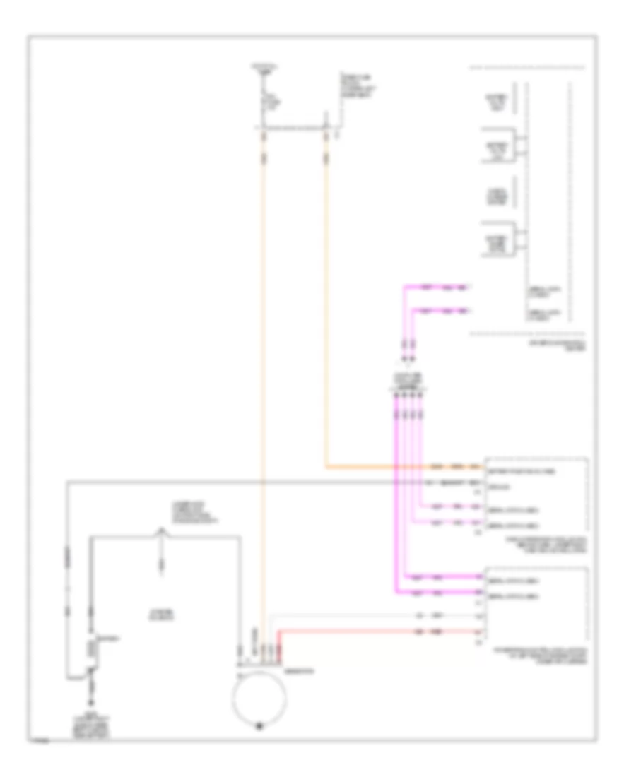
- Starting/ charging system
- Tach output
- Tcc brake switch input
- Tcc pwm sol cntrl
- Tcc/cruise release switch
- Tft sensor high
- Tft sensor low ref
- Tp sens 5v ref
- Tp sens low ref
- Trans range a input
- Trans range c input
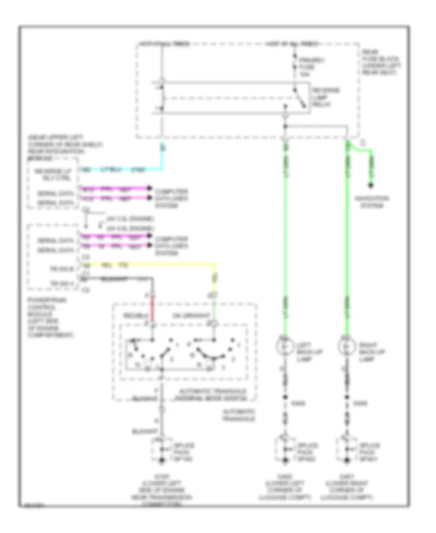
EXTERIOR LIGHTS
Back-up Lamps Wiring Diagram for Oldsmobile Aurora 2003
List of elements for Back-up Lamps Wiring Diagram for Oldsmobile Aurora 2003:
- (near upper left corner of rear shelf) rear integration module
- (w/ 3.5l engine)
- (w/ 4.0l engine)
- A12
- Automatic transaxle
- Automatic transaxle internal mode switch
- B12
- Computer data lines system
- G105 (lower left side of engine near transmission connector)
- G401 (lower right corner of luggage compt)
- G402 (lower left corner of luggage compt)
- Hot at all times
- Left back-up lamp
- Navigation system
- Powertrain control module (left side of engine compartment)
- Prk/rev fuse 10a
- Rear fuse block (under left rear seat)
- Reverse lamp relay
- Reverse lp rly ctrl
- Right back-up lamp
- S408
- S409
- Serial data
- Splice pack sp105
- Splice pack sp401
- Splice pack sp402
- Tr sw a
- Tr sw b
Exterior Lamps Wiring Diagram for Oldsmobile Aurora 2003
List of elements for Exterior Lamps Wiring Diagram for Oldsmobile Aurora 2003:
- Batt pos volt
- Center high mounted stop lamp
- Ctrl power out
- Dash integration module (behind dash, under right dash sound insulator)
- Dimr fuse 10a
- Driver information center
- F12
- G103 (right side of engine compt, mounted in front of underhood fuse block
- G200
- G201 (behind right kick panel)
- G401 (lower right corner of luggage compt)
- G402 (lower left corner of luggage compt)
- Ground
- Haz flash indicator
- Haz on sw
- Haz sw signal
- Hdlmp on signal
- Head
- Headlamp swiitch
- Hot at all times
- Hot in run & start
- Ign-1 fuse 10a
- Instrument cluster
- Left front park/ turn signal lamp
- Left rear turn signal lamp
- Left tail/ stop lamps
- Left turn indicator
- Lh trun input
- Lh turn lps volt
- License plate lamps
- Lp park l fuse 10a
- Lp park r fuse 10a
- Marker lamp
- Nca
- Off
- Park
- Park lps relay
- Pk lmp rel ctrl
- Pnk
- Rear fuse block (under left rear seat)
- Rh turn input
- Rh turn lps volt
- Right front park/ turn signal lamp
- Right rear turn signal lamp
- Right tail/ stop lamps
- Right turn indicator
- S209
- S216
- S250 (i/p round harn, under center console)
- S251 (i/p round harn, under center console)
- S309 (body harn, near rear fuse block)
- S329
- S406 (right tail lamp harness)
- S407 (left tail lamp harness)
- S408
- S409
- Sp200 (behind left kick panel)
- Splice pack sp103
- Splice pack sp201
- Splice pack sp304 (near forward crossmember, under left front seat)
- Splice pack sp401
- Splice pack sp402
- Stop lamp switch (on brake pedal support)
- Stop lp fuse 15a
- T/sig haz fuse 15a
- Tan
- Turn signal/ multifunction switch
- Turn signal/hazard flasher module (behind left side of i/p)
- Underhood fuse block (right side of engine compt)
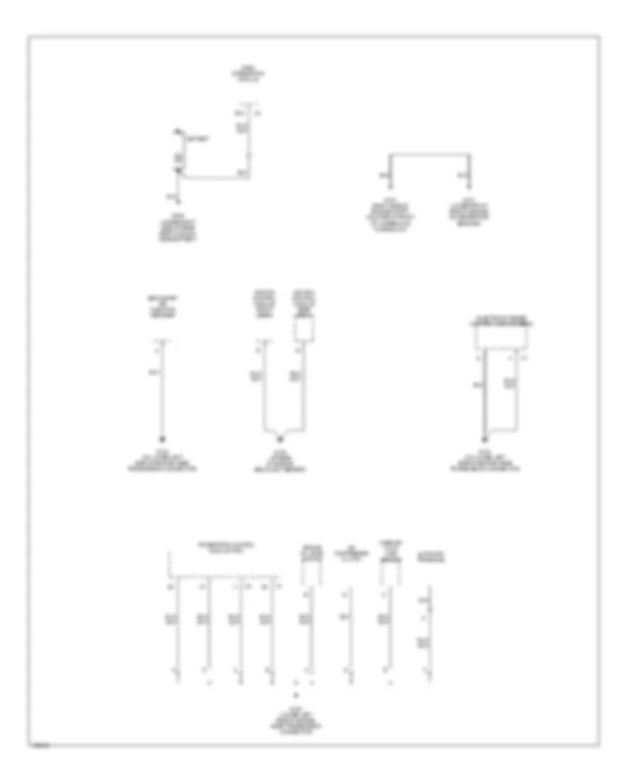
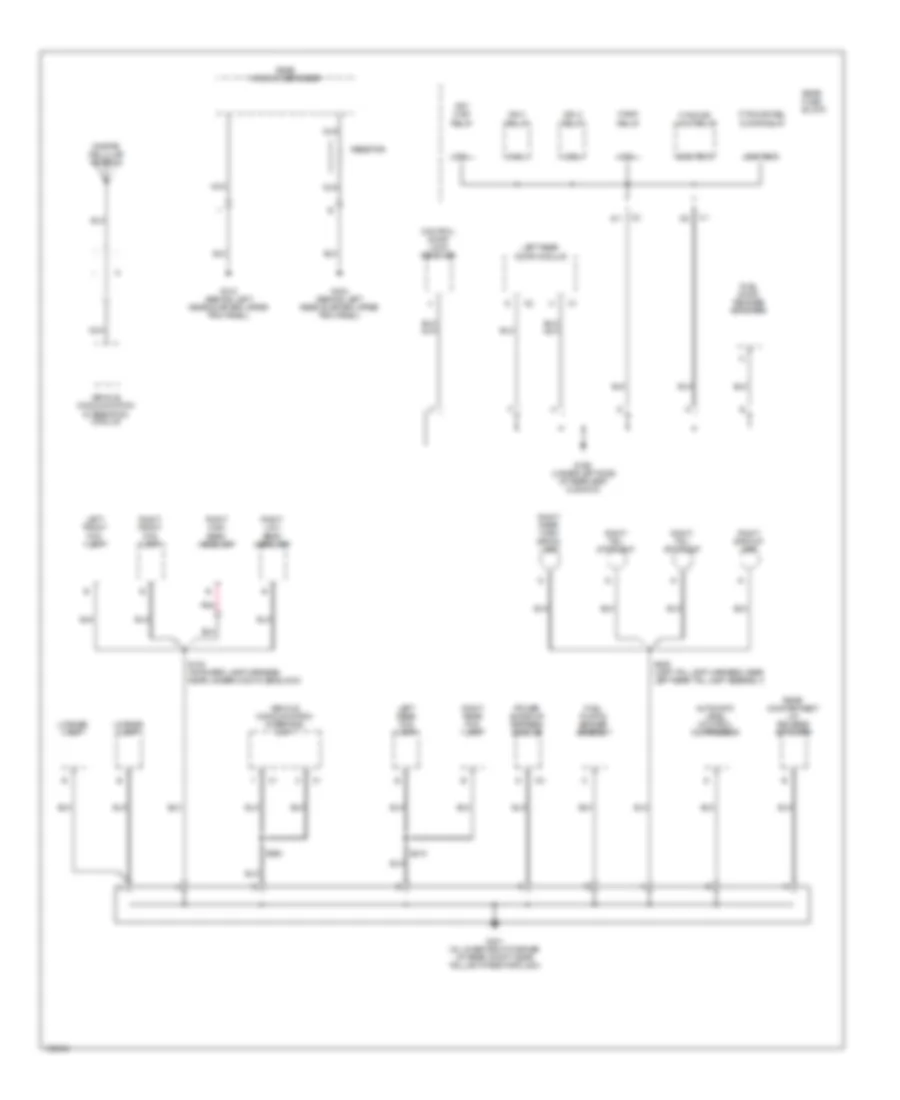
GROUND DISTRIBUTION
Ground Distribution Wiring Diagram (1 of 6) for Oldsmobile Aurora 2003
List of elements for Ground Distribution Wiring Diagram (1 of 6) for Oldsmobile Aurora 2003:
- A/c compressor clutch
- Automatic transaxle
- B12
- Battery
- Dash integration module
- Electronic brake control module (ebcm)
- Engine oil level switch
- G100 (lower left side of engine, near transmission connector)
- G101 (lower front side of engine, on generator bracket)
- G102 (on lower left side of engine, near transmission connector)
- G104 (on lower left side of engine, near transmission connector)
- G105 (at rear of engine, below ect sensor)
- G107 (right side of engine compt, mounted in front of underhood fuse block)
- G305 (under right side of rear seat cushion, near battery)
- Ignition control module front bank
- Ignition control module rear bank
- Mass air- flow (maf) sensor
- Nca
- Powertrain control module (pcm)
- Secondary air injection (air) pump
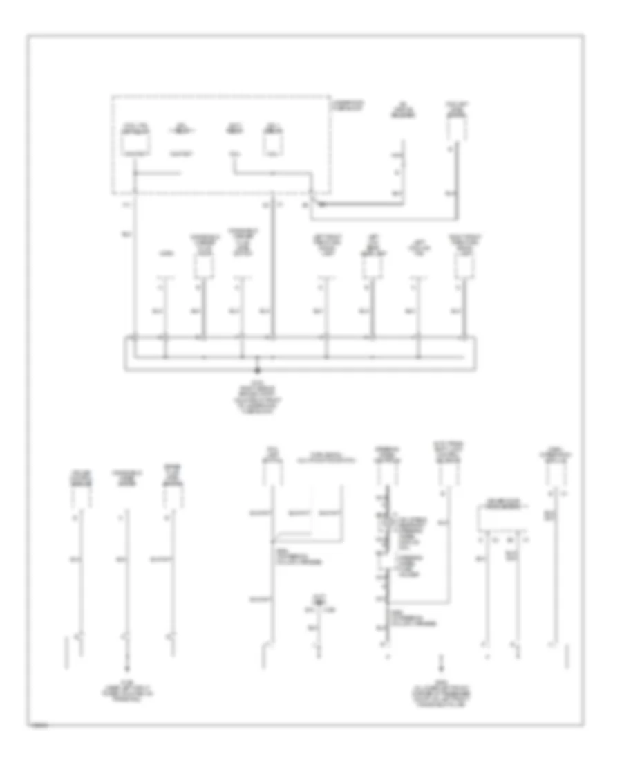
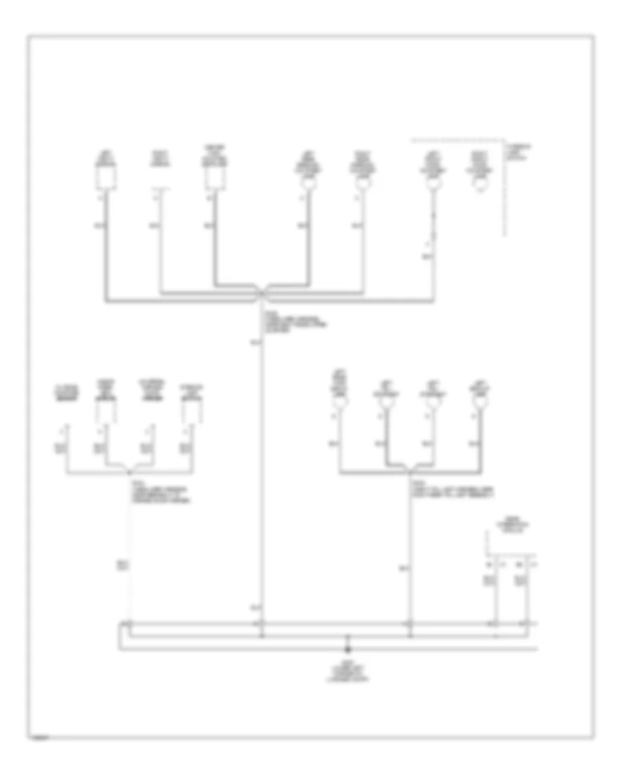
Ground Distribution Wiring Diagram (2 of 6) for Oldsmobile Aurora 2003
List of elements for Ground Distribution Wiring Diagram (2 of 6) for Oldsmobile Aurora 2003:
- (not used)
- A/c orifice solenoid
- Accy relay
- Auto trans shift lock control solenoid
- B12
- Brake fluid level switch
- C200
- Coil
- Contact
- Cool fan s/p relay
- Coolant level switch
- Cruise control module
- Dash integration module
- Driver door module (ddm)
- Drl relay
- F11
- Fog lamp switch
- G103 (right side of engine compt, mounted in front of underhood fuse block)
- G106 (near left strut tower, mounted on frame rail)
- G200 (in lower left front corner of passenger compt, on left front windshield pillar)
- Horn
- Ign-1 relay
- Inflatable restraint steering wheel module coil
- Left cooling fan
- Left front park/turn signal lamp
- Left low beam headlamp
- Nca
- Nca d
- Right front park/turn signal lamp
- S225 (in steering column harness)
- S226 (in steering column harness)
- Steering wheel controls
- Steering wheel fuse holder
- Turn signal/ multifunction switch
- Underhood fuse block
- Windshield washer fluid level switch
- Windshield washer fluid pump
- Windshield wiper motor
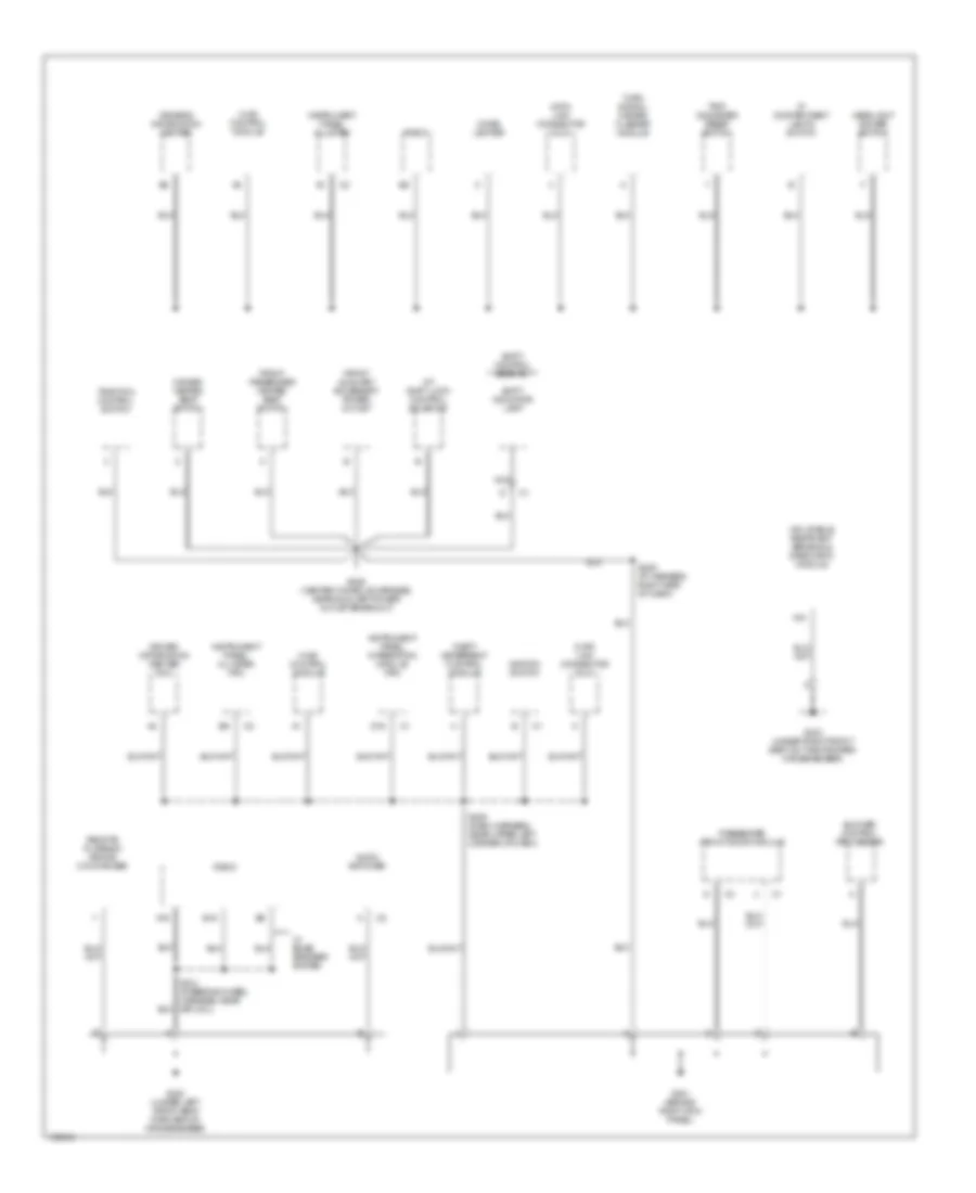
Ground Distribution Wiring Diagram (3 of 6) for Oldsmobile Aurora 2003
List of elements for Ground Distribution Wiring Diagram (3 of 6) for Oldsmobile Aurora 2003:
- A/t shift lock control solenoid
- A16
- A18
- Audio amplifier
- B16
- Blower control processor
- Cigar lighter
- D16
- Data link connector (dlc)
- Driver heated seat switch
- Driver information center (dic)
- Driver's information center
- Front auxiliary accessory power outlet
- Front passenger heated seat switch
- G201 (behind right kick panel)
- G300 (under left front seat forward of crossmember)
- G303 (under right front seat on the forward crossmember)
- Headlight dimmer switch
- Hvac control module
- Ignition switch
- Inflatable restraint sensing & diagnostic module
- Instrument panel cluster
- Instrument panel cluster (ipc)
- Instrument panel integration module (ipm)
- Ip compartment lamp & switch
- Nca
- Passenger front door module
- Radio
- Remote playback device cd changer
- S205 (dash harness, near upper left corner of dash)
- S209 (ip harness, right side of dash)
- S214 (steering wheel harness, near sir coil)
- S228 (center console harness, near auxiliary power outlet breakout)
- Shift control assembly
- Shift indicator lamp
- Theft deterrent control module
- Traction control switch
- Trip odometer reset switch
- Turn signal/ hazard flasher module
- W/ bose speaker system
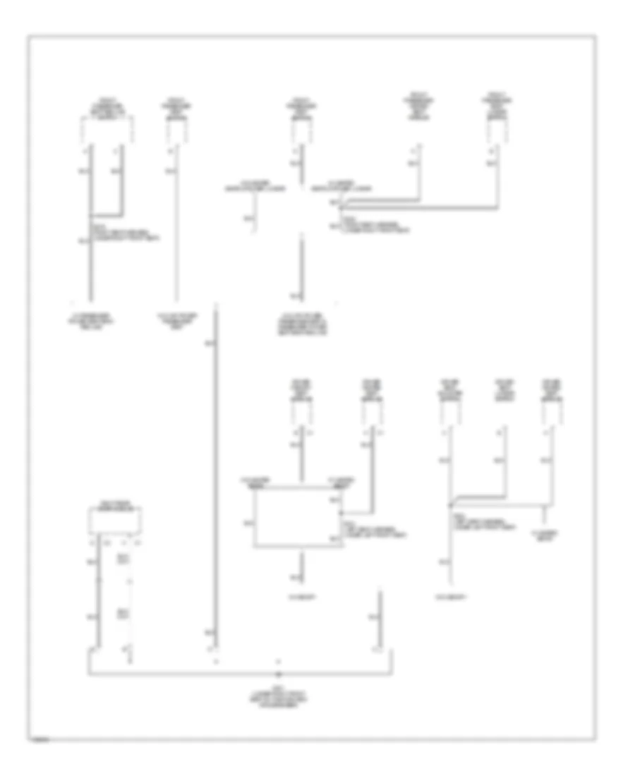
Ground Distribution Wiring Diagram (4 of 6) for Oldsmobile Aurora 2003
List of elements for Ground Distribution Wiring Diagram (4 of 6) for Oldsmobile Aurora 2003:
- Driver heated seat module
- Driver memory seat module
- Driver seat adjuster switch
- Driver seat lumbar switch
- Front passenger heated seat module
- Front passenger seat lumbar switch
- Front passenger seat recline switch
- Front passenger seat switch
- G301 (under right front seat on the forward crossmember)
- Right rear door module
- S324 (left seat harness, under left front seat)
- Under right front seat)
- W/ 6 way power passenger seat
- W/ 6 way power passenger seat & passenger power seat back recline
- W/ heated seats
- W/ heated seats & power lumbar
- W/ memory
- W/ passenger power seat back recline
- W/o heated seats
- W/o heated seats & power lumbar
- W/o memory
Ground Distribution Wiring Diagram (5 of 6) for Oldsmobile Aurora 2003
List of elements for Ground Distribution Wiring Diagram (5 of 6) for Oldsmobile Aurora 2003:
- A11
- Automatic level control compressor
- Coil
- Contact
- Control door lock receiver
- F/pmp relay
- F/tnk dr lock relay
- F/tnk dr rel door relay
- Frt ctsy relay
- Fuel door release actuator
- Fuel pump & sender assembly
- G302 (under left side of rear seat cushion)
- G310 (behind left rear quarter upper trim panel)
- G401 (in lower right corner of rear compt, near taillight pass-through)
- G404 (behind left rear quarter upper trim panel)
- Ign-1 relay
- Ign-3 relay
- Left front fog lamp
- Left rear door module
- Left rear fog lamp
- License lamp
- Nca
- Onstar cellular antenna
- Pnk
- Power sunroof express module
- Rear compartment lid release actuator
- Rear fuse block
- Rear window defogger
- Resistor
- Right backup lamp
- Right front fog lamp
- Right high beam headlamp
- Right low beam headlamp
- Right rear fog lamp
- Right rear turn signal lamp
- Right tail/ stoplamp
- S100 (forward lamp harness, near underhood fuse block)
- S360
- S409 (left tail lamp harness, near left rear tail lamp assembly)
- S415
- Vehicle communication integration module
- Vehicle communication interface unit
Ground Distribution Wiring Diagram (6 of 6) for Oldsmobile Aurora 2003
List of elements for Ground Distribution Wiring Diagram (6 of 6) for Oldsmobile Aurora 2003:
- Center high mounted stoplamp
- G402 (lower left corner of luggage compt)
- Inside rear view mirror
- Interior lamp switch
- Left backup lamp
- Left front door courtesy lamp
- Left rear reading/ courtesy lamp
- Left rear turn signal lamp
- Left tail/ stoplamp
- Left vanity mirror
- Outside moisture sensor
- Rear integration module
- Right front door courtesy lamp
- Right rear reading/ courtesy lamp
- Right vanity mirror
- S329 (headliner harness, near right rear upper quarter)
- S334 (headliner harness, near breakout to garage door opener)
- S408 (right tail lamp harness, near right rear tail lamp assembly)
- Universal garage door opener
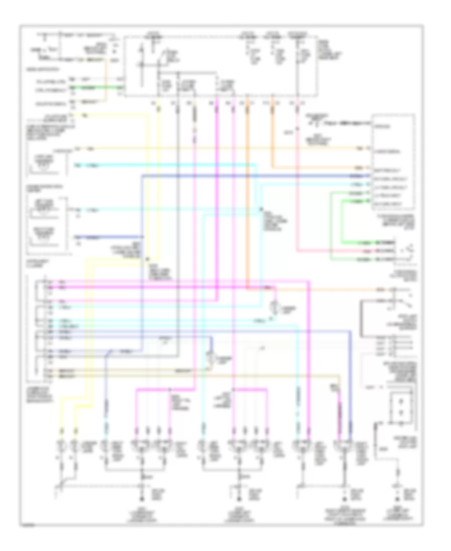
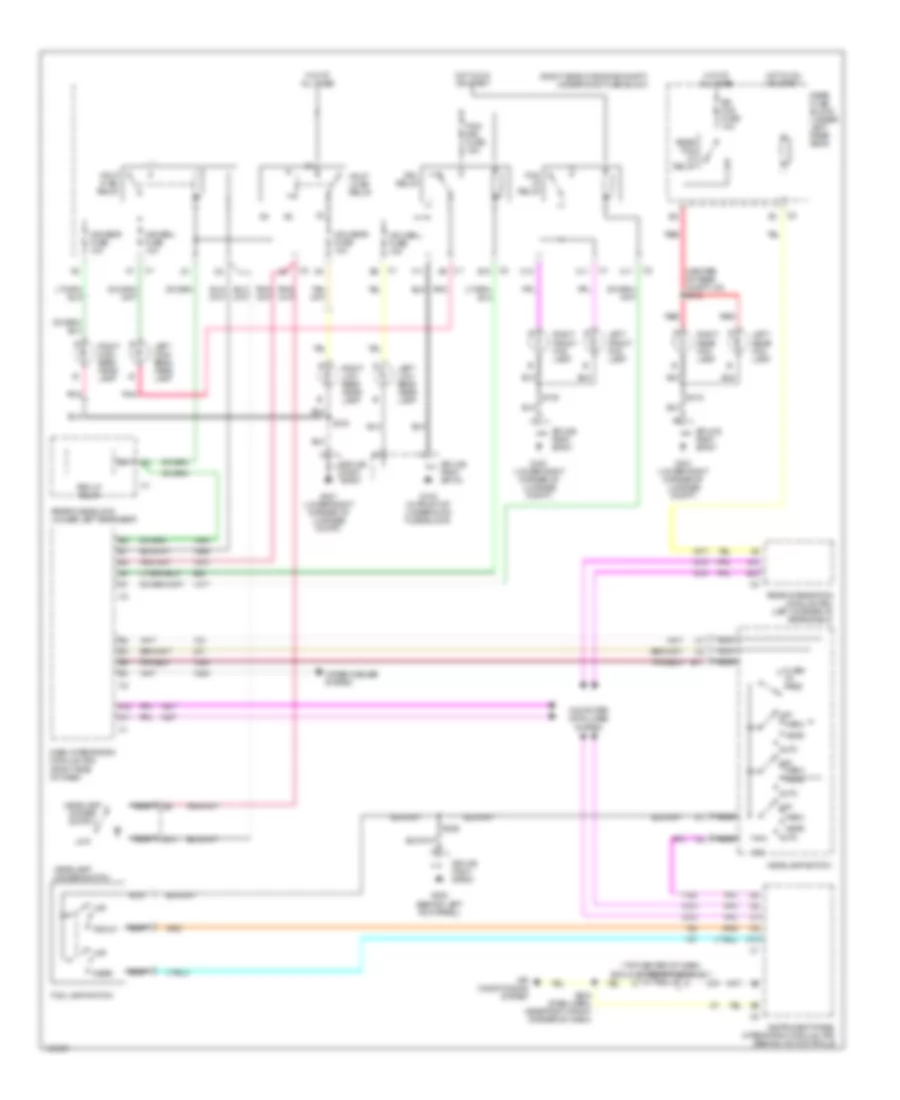
HEADLIGHTS
Headlights Wiring Diagram for Oldsmobile Aurora 2003
List of elements for Headlights Wiring Diagram for Oldsmobile Aurora 2003:
- (center of rear compt lid) s412
- (right side of engine compt) underhood fuse block
- (top center of dash) sunload sensor assembly
- 10k
- A11
- A12
- Air conditioning system
- Auto
- B10
- B11
- B12
- C1 a9
- C10
- C11
- Computer data lines system
- Dash integration module (dim) (right side of dash)
- Drl relay
- F11
- Flash to pass
- Fog lamp switch
- Fog lp relay
- Fog/ drl fuse 15a
- Front
- G103 (in front of underhood fuse block)
- G200 (behind left kick panel)
- G401 (lower right corner of luggage compt)
- Hdhibml fuse 10a
- Hdhibmr fuse 10a
- Hdlobnl fuse 10a
- Hdlobnr fuse 10a
- Hdlp hi bm relay
- Hdlp lo bm relay
- Head
- Headlamp dimmer switch
- Headlamp switch
- Hot at all times
- Hot in on or start
- Instrument panel integration module (ipm) (behind a/c controls)
- Left front fog lamp
- Left high beam head- lamp
- Left low beam head- lamp
- Left rear fog lamp
- Low
- Nca
- Off
- Park
- Pnk
- Prk lp relay
- Rear
- Rear fog lp relay
- Rear fuse block (under left rear seat)
- Rear integration module (rim) (left corner of rear shelf)
- Red
- Right front fog lamp
- Right high beam head- lamp
- Right low beam head- lamp
- Right rear fog lamp
- Rr fog fuse 10a
- S100
- S204 (dash harn, near right front corner of dash)
- S226
- S415
- Splice pack sp103
- Splice pack sp200
- Splice pack sp401
- Wiper/washer system
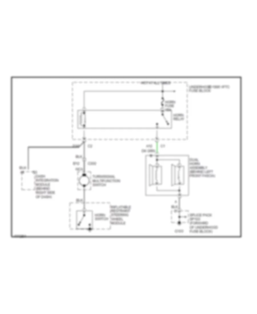
HORN
Horn Wiring Diagram for Oldsmobile Aurora 2003
List of elements for Horn Wiring Diagram for Oldsmobile Aurora 2003:
- 1995 vftc c
- A12
- B12
- C202
- D10
- Dash integration module (behind right side of dash)
- Dual horn assembly (behind left front fascia)
- G103
- Horn fuse 15a
- Horn relay
- Horn switch
- Hot at all times
- Inflatable restraint steering wheel module
- Nca
- Splice pack sp103 (forward of underhood fuse block)
- Turn/signal multifunction switch
- Underhood fuse block
INSTRUMENT CLUSTER
Instrument Cluster Wiring Diagram (1 of 2) for Oldsmobile Aurora 2003
List of elements for Instrument Cluster Wiring Diagram (1 of 2) for Oldsmobile Aurora 2003:
- Abs indicator
- Abs sig
- Air bag indicator
- Anti-lock brake system
- Battery
- Battery charge indicator
- Brake warning indicator
- C11
- Class 2 data
- Computer data lines system
- Cruise indicator
- Data lines
- Dic sw
- Engine control system
- Engine coolant temperature gauge
- Exterior lights system
- Fog lamp indicator
- Fuel gauge
- G203 (behind right kick panel)
- Ground
- Hi beam indicator
- Hot at all times
- Hot in run
- Hot in run or off
- Ign
- Ign 1 fuse 10a
- Ign 3 rr fuse 10a
- Ignition
- Illumination
- Instrument cluster (ipc)
- Interior lights system
- Ip fuse 10a
- Left turn ind
- Low coolant
- Malfunction indicator lamp
- Oil pressure indicator
- Park brake switch (on parking brake lever)
- Park brk in
- Pnk
- Rear fuse block (under left rear seat)
- Right turn ind
- S200
- S205
- S206
- S209
- S216
- Safety belt indicator
- Security indicator
- Speed signal
- Speedometer
- Tachometer
- Trac off indicator
- Trac on indicator
- Trip reset sw
- Washer level sw signal brk fluid in
- Wiper/ washer system
Instrument Cluster Wiring Diagram (2 of 2) for Oldsmobile Aurora 2003
List of elements for Instrument Cluster Wiring Diagram (2 of 2) for Oldsmobile Aurora 2003:
- (in body harness, 31.5 cm from fuel tank harness breakout)
- 5v ref
- Backlight
- Brake fluid level switch (on brake fluid reservoir)
- Computer data lines system
- Data
- Driver information center (dic)
- Engine oil level switch (at front of engine oil pan)
- Engine oil pressure sensor (3.5l) (on right front side of engine)
- Engine oil pressure sensor (4.0l) (on left side of engine, near oil filter housing
- Exterior lights system
- Fuel pump & sender assembly (in fuel tank)
- Fuel sender
- Fuel signal
- G100 (on lower left side of engine, near transmission)
- G102 (near left strut tower, mounted on framerail)
- G201 (behind right kick panel)
- Ground
- Haz sw sig
- Interior lights system
- Lf turn sig
- Lo ref
- Mil control
- Navigation system
- Oil lev sw sig
- Oil press sig
- Powertrain control module (pcm) (at left side of engine compt, under air cleaner)
- S205
- S209
- S215 (body harness, left side of vehicle, 7.6 cm from bulkhead)
- S401
- Tach signal
- Tan
- Trip a/b
- Trip odometer reset switch
- Trip reset
- Vss signal
INTERIOR LIGHTS
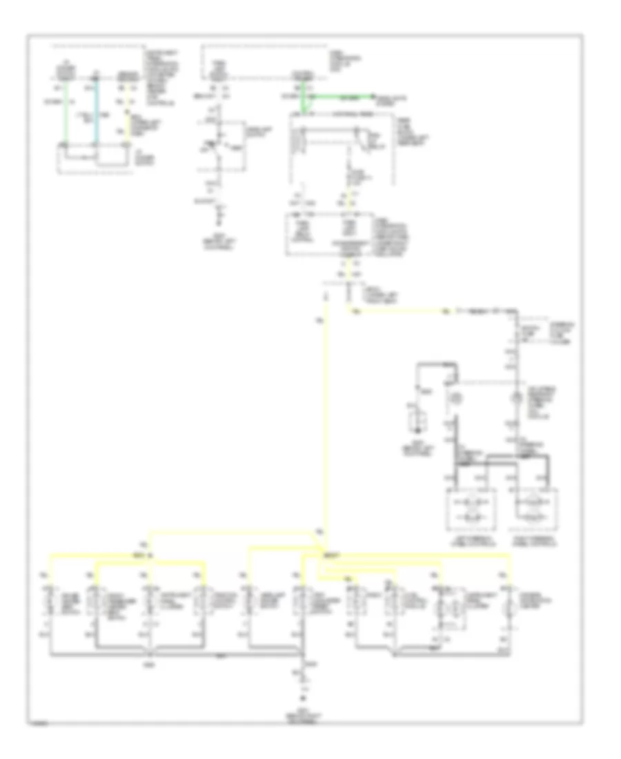
Courtesy Lamps Wiring Diagram (1 of 2) for Oldsmobile Aurora 2003
List of elements for Courtesy Lamps Wiring Diagram (1 of 2) for Oldsmobile Aurora 2003:
- (not used)
- A12
- B12
- C1 a
- C1 d
- Class 2 serial data line
- Computer data lines system
- D12
- D400
- Door locks system
- Driver door lock actuator
- Driver door module
- E11
- E12
- From right courtesy lamp switch (diagram 2 of 2)
- From s332 (diagram 2 of 2)
- Front courtesy rly control
- Front passenger door lock actuator
- Front passenger door module
- Frt ctsy relay
- G302 (under left side of rear seat cushion)
- G401 (lower right corner of luggage compt)
- Ground
- Hot at all times
- Int lp fuse 10a
- Int lp relay
- Interior lamp rly control
- Left footwell courtesy lamp
- Left front door courtesy lamp
- Left front door open input
- Left rear door courtesy lamp
- Left rear door lock actuator
- Left rear door module
- Left rear door open input
- Pwr door serial data
- Rear compartment courtesy lamp
- Rear compartment lid release switch
- Rear fuse block (under left rear seat)
- Rear integration module (rim) (near upper left corner of rear shelf panel)
- Right front door open input
- Right rear door lock actuator
- Right rear door module
- Right rear door open input
- S215 (body harn, left side of vehicle)
- S420
- S421
- Serial data class 2
- Sp306 (near rear fuse block breakout)
- Tan
- To s333 (diagram 2 of 2)
- To sp310 (diagram 2 of 2)
- Trunk ajar sw signal
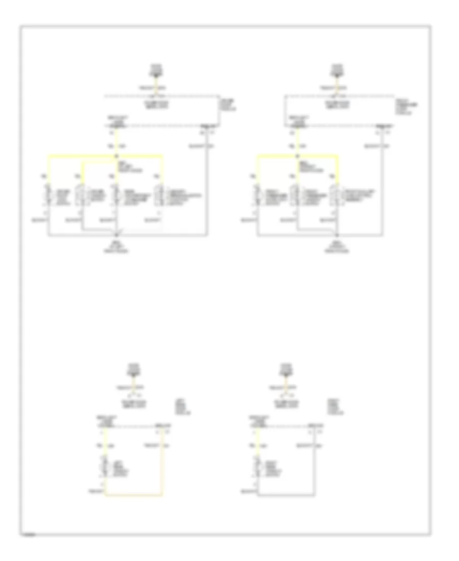
Courtesy Lamps Wiring Diagram (2 of 2) for Oldsmobile Aurora 2003
List of elements for Courtesy Lamps Wiring Diagram (2 of 2) for Oldsmobile Aurora 2003:
- A10
- B10
- D13
- Door
- From rear fuse block (diagram 1 of 2)
- From sp306 (diagram 1 of 2)
- G201 (behind right kick panel)
- G402 (lower left corner of luggage compt)
- Hot at all times
- I/p compartment lamp
- I/p compartment switch
- Ignition key cylinder lamp
- Instrument panel integration module (ipm) (at center of dash, behind heater & a/c controls)
- Interior lamp control
- Interior lamp sw on sig
- Interior lamp sw signal
- Interior lamp switch
- Ip fuse 10a
- Key cylinder lamp control
- Left reading/ courtesy lamp
- Left rear reading/ courtesy lamp
- Left vanity mirror
- Off
- Overhead console
- Rear fuse block (under left rear seat)
- Rear integration module (rim) (near upper left corner of rear shelf panel)
- Right footwell courtesy lamp
- Right front door courtesy lamp
- Right reading/ courtesy lamp
- Right rear door courtesy lamp
- Right rear reading/ courtesy lamp
- Right vanity mirror
- S206
- S209
- S329
- S332
- S333
- Sp310 (18 cm from rear fuse block breakout)
- To front courtesy relay (diagram 1 of 2)
- To sp306 (diagram 1 of 2)
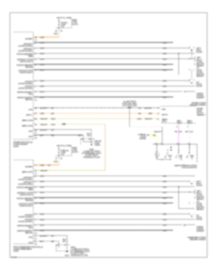
Instrument Illumination Wiring Diagram (1 of 2) for Oldsmobile Aurora 2003
List of elements for Instrument Illumination Wiring Diagram (1 of 2) for Oldsmobile Aurora 2003:
- (in nca
- (in steering wheel) s228
- 5v ref
- A3 c2
- B11
- B12
- C1 a4
- C2 b3
- C2 b8
- C3 b8
- Control power
- D c1
- Dash integration module (dim)
- Dash integration module (dim) (behind dash, under right dash sound insulator)
- Dimr fuse 14 10a
- Driver heated seat switch
- Drivers information center
- Front passenger heated seat switch
- G200 (behind left kick panel)
- G201 (behind right kick panel)
- Head
- Headlamp dimmer switch
- Headlamp switch
- Headlights system
- Hot at all times
- Hvac control module
- I/p dimmer switch
- I/p dimmer switch input
- Incandescent dimming output
- Inflatable restraint steering wheel coil module
- Instrument panel cluster
- Instrument panel integration module (ipm) (at center of dash, behind heater & a/c controls)
- Left steering wheel controls
- Nca
- Off
- Park
- Park lamp input
- Park lamp relay control
- Park lamp switch input
- Prk lp relay
- Radio
- Rear fuse block (under left rear seat)
- Right steering wheel controls
- S204 (upper left corner of dash)
- S207
- S209
- S223
- S225
- S228
- Sensor return
- Sp301 (under left front seat)
- Steering column fuse holder
- Steering wheel) s227
- Switch fuse 2a
- Traction control switch
- Trip odometer reset switch
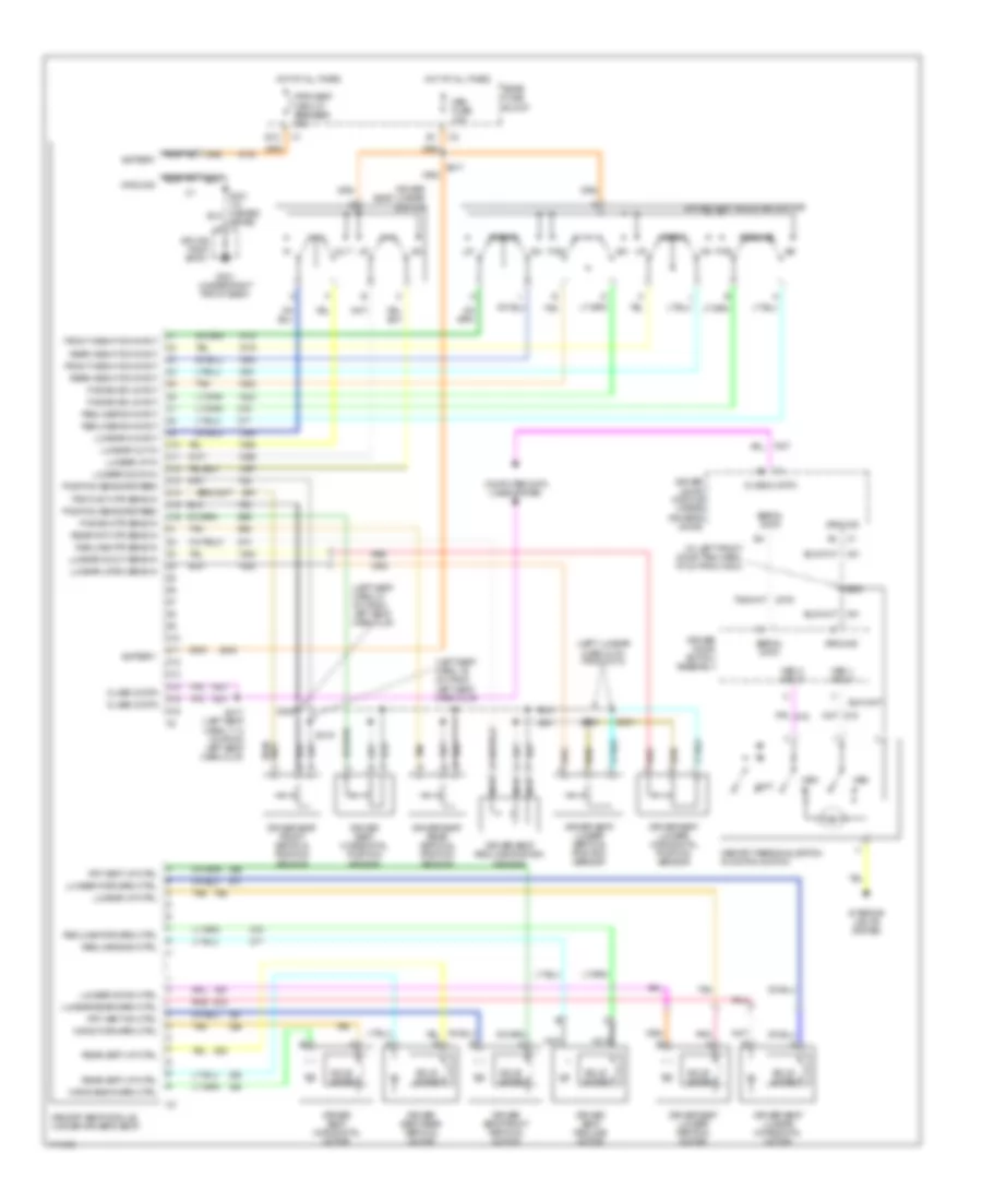
Instrument Illumination Wiring Diagram (2 of 2) for Oldsmobile Aurora 2003
List of elements for Instrument Illumination Wiring Diagram (2 of 2) for Oldsmobile Aurora 2003:
- Backlight lamps control
- Door locks system
- Driver door lock switch
- Driver door module
- Driver window switch
- Front auxiliary hvac control assembly
- Front passenger door lock switch
- Front passenger door module
- Front passenger window switch
- Ground
- Left rear door module
- Left rear window switch
- Memory/ personalization function switch
- Power door serial data
- Rear compartment lid release switch
- Right rear door module
- Right rear window switch
- S500 (in left front door)
- S501 (in left front door)
- S603 (in right front door)
- S604 (in right front door)
MEMORY SYSTEMS
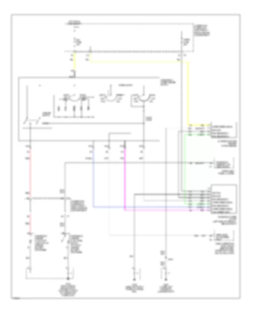
Memory Mirrors Wiring Diagram for Oldsmobile Aurora 2003
List of elements for Memory Mirrors Wiring Diagram for Oldsmobile Aurora 2003:
- (in left front door trim harn, 19 cm from c503)
- A up/down motor position input
- B left/right motor position input
- Batt(+)
- Battery
- Driver door module (inside driver's door)
- Driver door switch assembly
- Driver outside rearview mirror
- Drvmdl fuse 10a
- E postion sensors return
- Exit
- Front passenger door module (inside passenger's door)
- G200 (lower left front of passenger compt, on left front windshield pillar)
- G201
- Gnd
- Heating element pwr
- Heating element return
- Hot at all times
- Interior lights system
- J left/right motor control
- K up/down motor control
- Left/ right motor
- Left/ right motor position sensor
- Left/right motor control
- M postion sensors feed
- Mem
- Mem 1 input
- Mem 2 input
- Memory/personalization function switch
- Mirror heating element
- Motor control
- Nca
- Pass mdl fuse 10a
- Passenger outside rearview mirror
- Rear fuse block
- S302
- S500
- Serial data
- Sp201 (lower right front of passenger compt, on right front windshield pillar)
- Splice pack sp200
- Up/ down motor
- Up/ down motor position sensor
- Up/down l
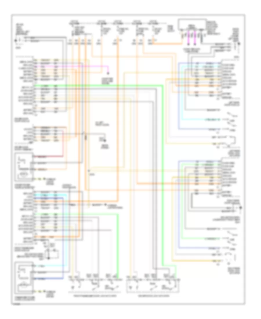
Memory Seat Wiring Diagram for Oldsmobile Aurora 2003
List of elements for Memory Seat Wiring Diagram for Oldsmobile Aurora 2003:
- (in left front door trim harn, 19 cm from c503)
- (left lumbar harn, 5 cm from c314)
- (left seat harn, 16 cm from left seat harn clip)
- (left seat harn, 21 cm from left seat harn clip)
- Battery
- C10
- C11
- C12
- C13
- C14
- C15
- C16
- Class 2 data
- Computer data lines system
- D10
- D11
- D12
- D13
- D14
- D15
- D16
- Driver door module (inside driver's door)
- Driver door switch assembly
- Driver seat adjuster switch
- Driver seat front vertical motor
- Driver seat front vertical position sensor
- Driver seat horizontal motor
- Driver seat horizontal position sensor
- Driver seat lumbar horizontal motor
- Driver seat lumbar horizontal position sensor
- Driver seat lumbar switch
- Driver seat lumbar vertical motor
- Driver seat lumbar vertical position sensor
- Driver seat rear vertical motor
- Driver seat rear vertical position sensor
- Driver seat recline motor
- Driver seat recline position sensor
- E12
- Exit
- Frnt hgt mtr sens in
- Front
- Front height sw input
- Frt vert dn ctrl
- Frt vert up ctrl
- Fwd
- Fwd-bk mtr sens in
- Fwd/bk sw unput
- G301 (under right front seat)
- Ground
- Horiz backward ctrl
- Horiz forward ctrl
- Hot at all times
- Interior lights system
- Lumbar down ctrl
- Lumbar down in
- Lumbar forward ctrl
- Lumbar in input
- Lumbar in/out sens in
- Lumbar out in
- Lumbar rearward ctrl
- Lumbar up ctrl
- Lumbar up in
- Lumbar up/dn sens in
- Mem
- Mem 1 input
- Mem 2 input
- Mem fuse 10a
- Memory personalization funciton switch
- Memory seat module (under driver's seat)
- Nca
- Out
- Pnk
- Pnk a
- Position sensors feed
- Pwr seat circuit breaker 30a
- Rear
- Rear fuse block
- Rear height sw input
- Rear hgt mtr sens in
- Rear vert up ctrl
- Recline
- Recline back ctrl
- Recline forward ctrl
- Recline mtr sens in
- Recliner sw input
- Red
- S317
- S317 (left seat harn, 11.5 cm from left seat harn clip)
- S319
- S320
- S330
- S331
- S500
- Seats)
- Serial data
- Solid state
- Splice pack sp301
- Tan
NAVIGATION
Navigation Wiring Diagram for Oldsmobile Aurora 2003
List of elements for Navigation Wiring Diagram for Oldsmobile Aurora 2003:
- A16
- Audio fuse 10a
- B16
- Backup lamp voltage
- Bare
- Cell phone low ref
- Cell phone voice sig
- Coax cable
- Drain wire
- Exterior lights system
- G201 (in lower right corner of passenger compt, on right front windshield pillar)
- G300 (under right front seat, on forward crossmember)
- Global positioning system antenna (top center of dash pad)
- Gps antenna sig
- Ground
- Hot at all times
- Instrument cluster system
- Low reference
- Park/rev fuse 10a
- Radio
- Rear fuse block
- Rear integration module (near upper left corner of rear shelf panel)
- Rev lamp relay ctrl
- Reverse relay
- S209
- S214
- Signal
- Splice pack sp201
- Splice pack sp300
- Vehicle communication interface unit (behind rear seat back)
- Vss
- W/ bose speaker system
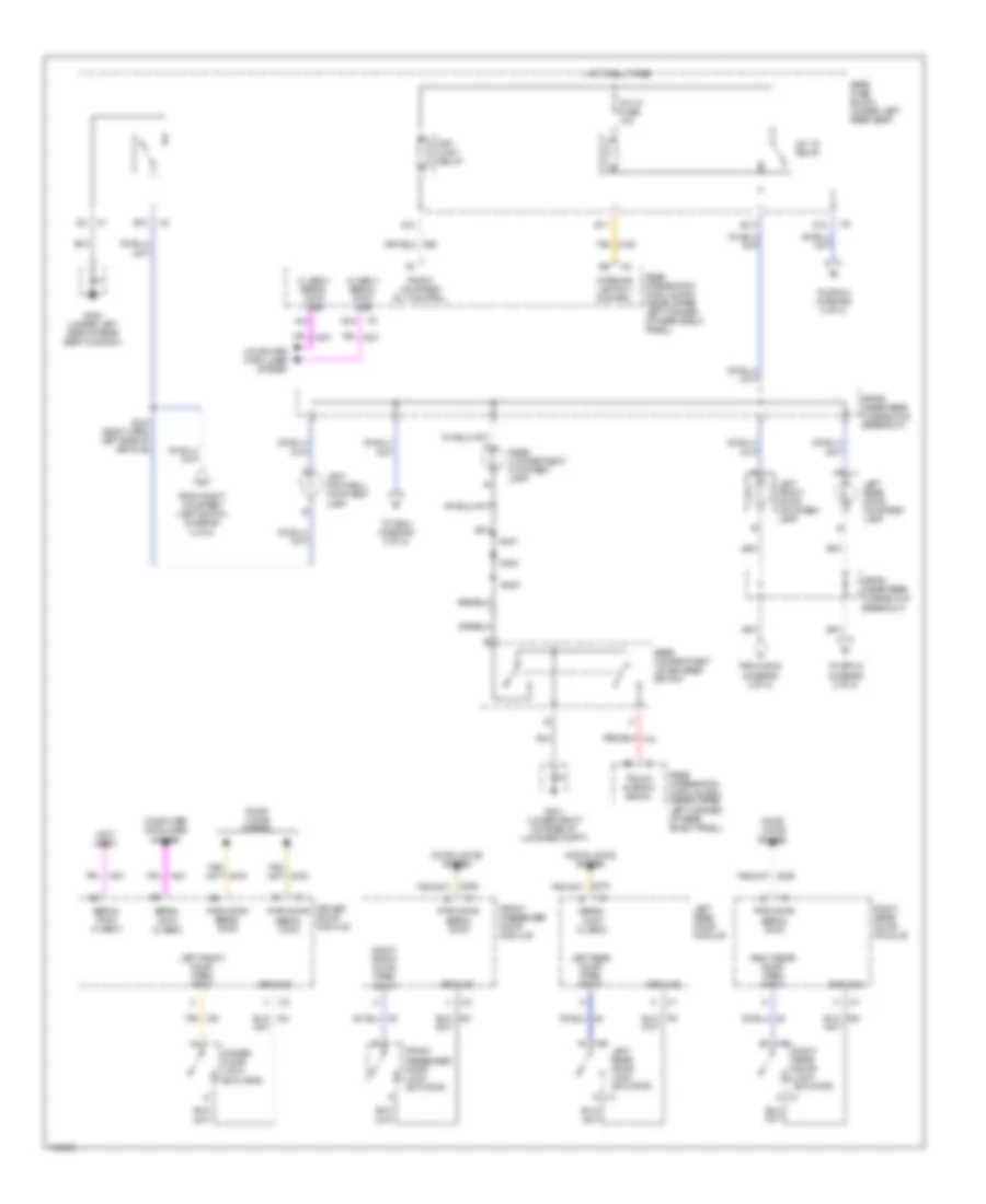
POWER DISTRIBUTION
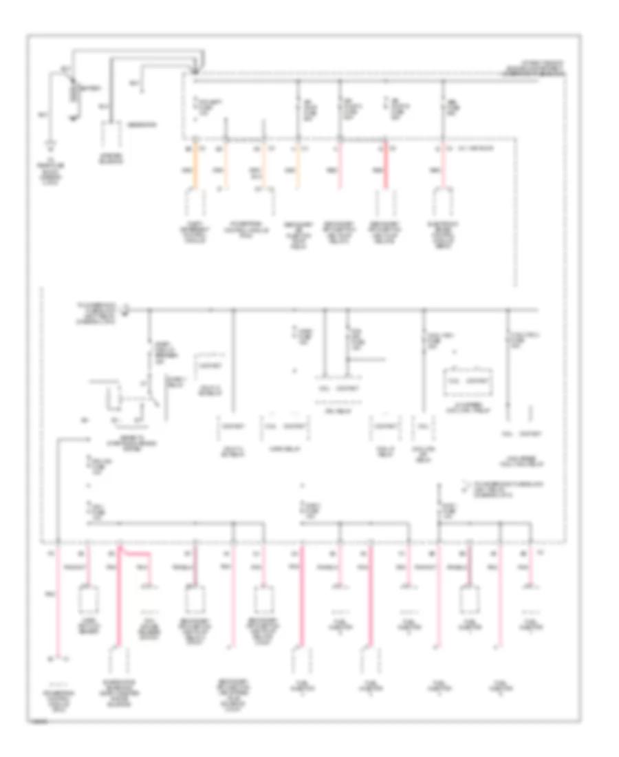
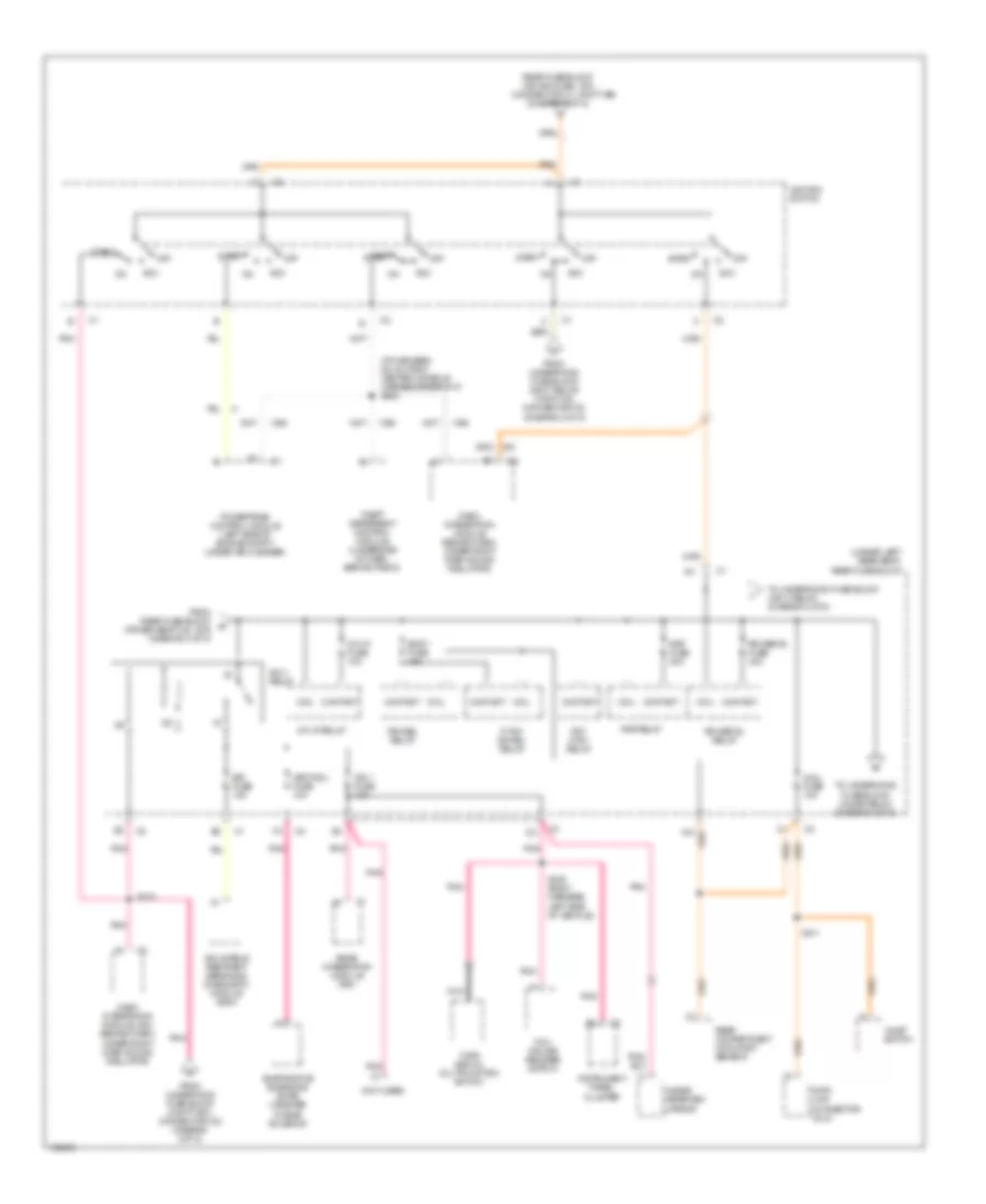
Power Distribution Wiring Diagram (1 of 5) for Oldsmobile Aurora 2003
List of elements for Power Distribution Wiring Diagram (1 of 5) for Oldsmobile Aurora 2003:
- (at right side of engine compartment) underhood fuse block
- (w/ 1 air pump)
- Abs fuse 50a
- Air pump a fuse 50a
- Air pump b fuse 50a
- Air pump fuse 50a
- Battery
- Coil
- Contact
- Cool fan 1 fuse 30a
- Cool fan 2 fuse 30a
- Cool fan s/p relay
- Drl relay
- Electronic brake control module (ebcm)
- Evaporative emissions (evap) canister purge solenoid
- Fog drl fuse 15a
- Fog lp relay
- Fuel injector
- Generator
- Hdlp hi bm relay
- Hdlp lo bm relay
- High speed cool fan 2 relay
- Horn fuse 15a
- Horn relay
- Ign 1 fuse 10a
- Injr 1 fuse 10a
- Injr 2 fuse 10a
- Low speed cool fan 1 relay
- Mass air flow sensor
- Pcm batt fuse 10a
- Pcm ign fuse 10a
- Pnk
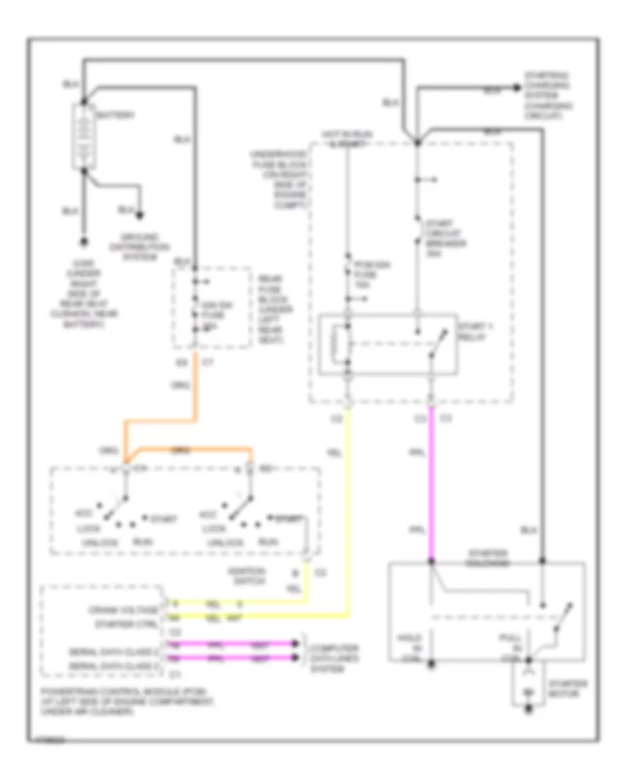
- Powertrain control module (pcm)
- Red
- Refer to starting/charging system
- Secondary air injection (air) bypass valve solenoid (calif)
- Secondary air injection (air) pump relay a
- Secondary air injection (air) pump relay a (calif)
- Secondary air injection (air) pump relay b
- Secondary air injection (air) pump relay b (calif)
- Secondary air injection pump relay
- Start 1 relay
- Start circuit breaker 30a
- Starter solenoid
- Tcc/ cruise release switch
- Theft deterrent control module
- To rear fuse block (diagram 2 of 5)
- To underhood fuse block (accy relay) (diagram 2 of 5)
- To underhood fuse block (ign 1 relay) (diagram 2 of 5)
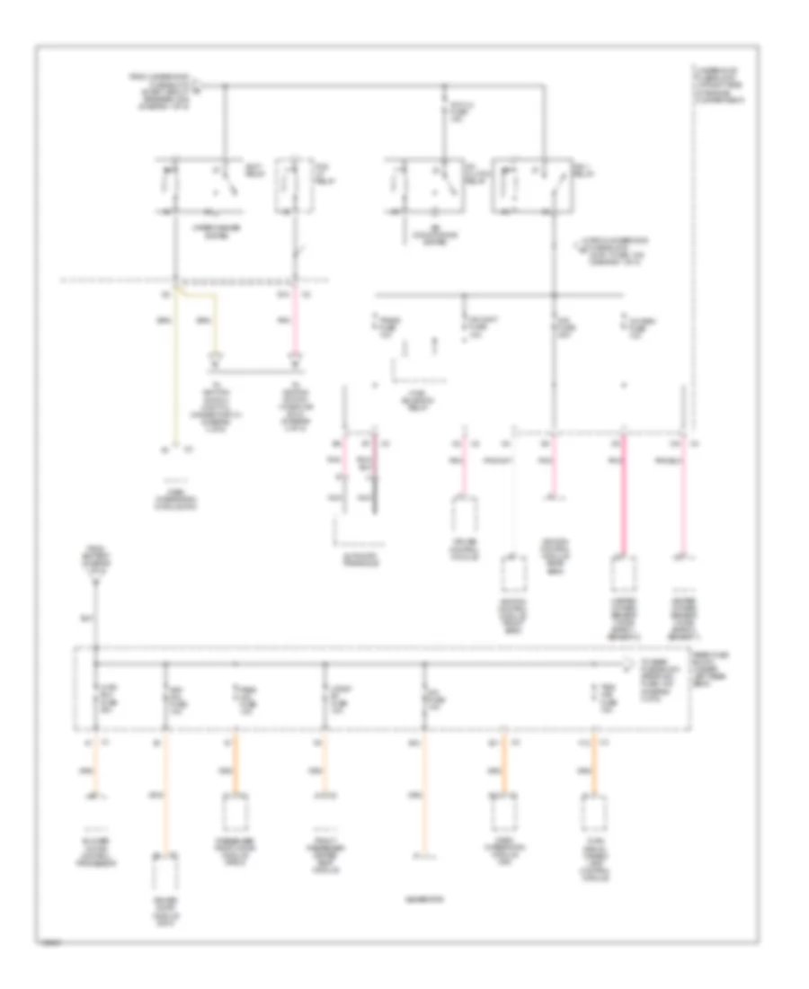
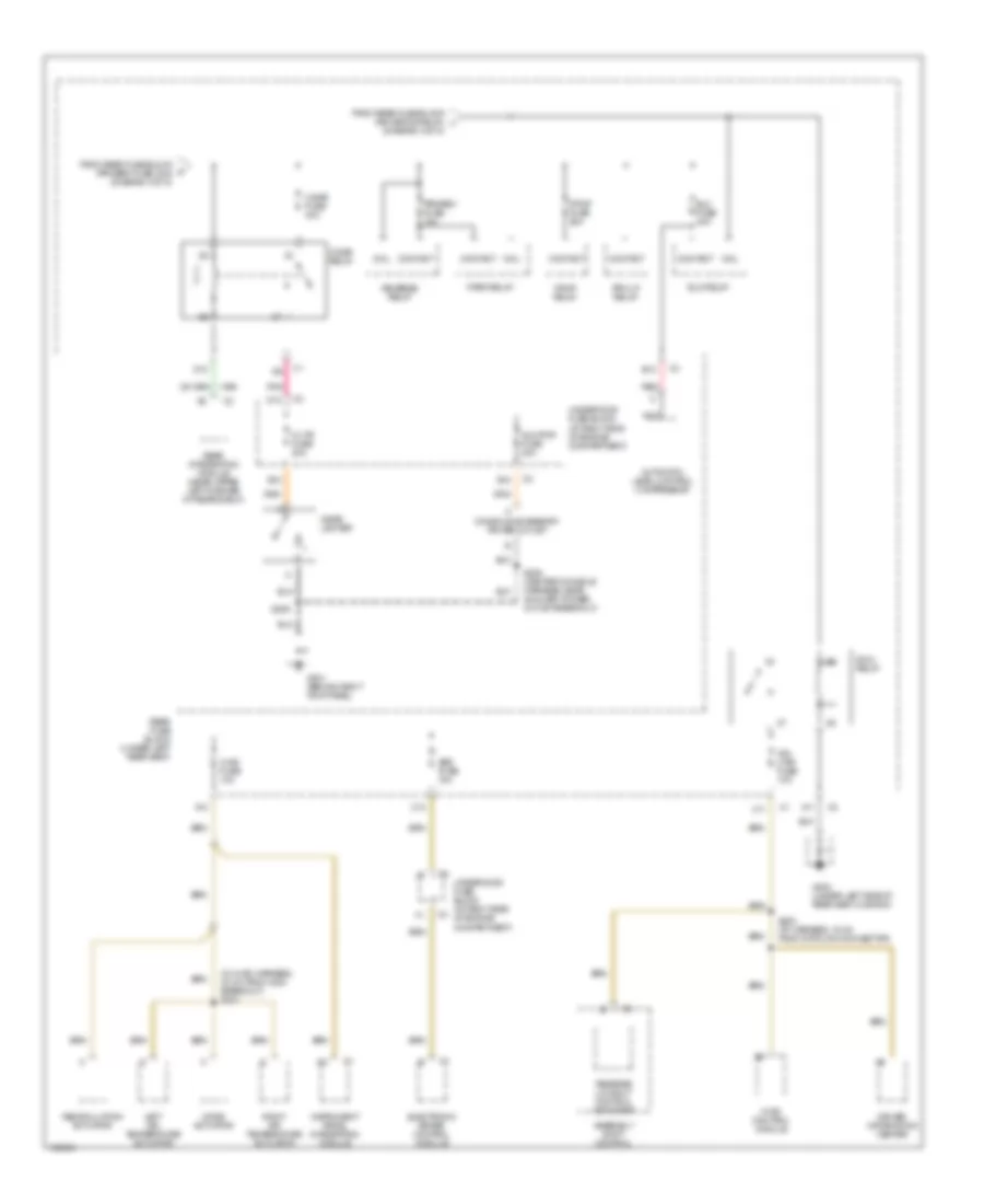
Power Distribution Wiring Diagram (2 of 5) for Oldsmobile Aurora 2003
List of elements for Power Distribution Wiring Diagram (2 of 5) for Oldsmobile Aurora 2003:
- A/c clu fuse 15a
- A/c clutch relay
- A12
- Accy relay
- Air conditioning system
- Automatic transaxle
- B12
- Blower motor control processor
- Cr cont fuse 10a
- Cruise control module
- Dash integration module (dim)
- Dim fuse 10a
- Dis fuse 20a
- Driver door module (ddm)
- Drv mdl fuse 10a
- E10
- E11
- F12
- Fog lp relay
- From battery (diagram 1 of 5)
- From underhood fuse block (injr 1 fuse, 10a) (diagram 1 of 5)
- From underhood fuse block (start circuit breaker, 30a) (diagram 1 of 5)
- Front passenger heated seat module
- Generator
- Heated oxygen sensor (ho2s) (bank 1, sensor 2)
- Heated oxygen sensor (ho2s) (bank 2, sensor 1)
- Htdst rf fuse 10a
- Hvac blo fuse 30a
- Hvac solenoid relay
- Ign 1 relay
- Ignition control module front bank
- Ignition control module rear bank
- Nca
- Oxy sen fuse 10a
- Pass mdl fuse 10a
- Passenger front door module (pfdm)
- Pnk
- Rear fuse block (under left rear seat)
- To ignition switch (cavity c, connector c1) (diagram 4 of 5)
- To ignition switch (via splice s210) (diagram 4 of 5)
- To rear fuse block (rrdr mdl fuse, 10a) (diagram 3 of 5)
- Trans fuse 10a
- Tsig/ haz fuse 15a
- Turn signal/ hazard lamp control module
- Underhood fuse block (at right side of engine compartment)
- Wiper/washer system
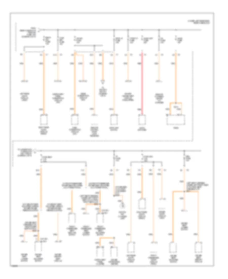
Power Distribution Wiring Diagram (3 of 5) for Oldsmobile Aurora 2003
List of elements for Power Distribution Wiring Diagram (3 of 5) for Oldsmobile Aurora 2003:
- (driver seat harness, 6 cm from power seat switch) s325
- (i/p harness, 13 cm from c216 break- out) s206
- (left seat harness, under left front seat, 21 cm from seat harness clip) s317
- (left seat harness, under left front seat, 9.5 cm from right seat clip) s323
- (under left rear seat) rear fuse block
- (w/ a81)
- (w/o a81)
- A11
- Audio amp fuse 20a
- Audio amplifier
- Audio fuse 10a
- Cd fuse 10a
- D12
- Dash integration module (dim)
- Driver door module (ddm)
- Driver heated seat module (if equipped)
- Driver information center
- Driver memory seat module
- Driver seat adjuster switch
- Driver seat lumbar switch
- Driver seat memory module
- E10
- E12
- F12
- From rear fuse block (tsig/haz fuse, 15a) (diagram 2 of 5)
- Front passenger door module (pfdm)
- Front passenger seat adjuster switch
- Front passenger seat lumbar switch
- Front passenger seat recline switch
- H a
- Htdst lf fuse 10a
- Hvac bat fuse 10a
- I/p fuse 10a
- Ign sw fuse 15a
- Ignition key cylinder lamp
- Instrument panel cluster
- Instrument panel integration module (ipm)
- Left rear door module (lrdm)
- Mem fuse 10a
- Pwr seat c.b. 30a
- Pwr wdo c.b. 30a
- Radio
- Rear integration module (rim)
- Red
- Remote control door lock receiver
- Remote playback device cd changer
- Right rear door module (rrdm)
- Rrdr mdl fuse 10a
- S210
- Stop lp fuse 15a
- Stoplamp switch
- To ignition switch (diagram 4 of 5)
- To underhood fuse block (ign 1 relay) (diagram 4 of 5)
- W/ front passenger power seat adjuster, multi-directional
- W/ memory seat adjuster, mirror, power driver personalization
- W/o front passenger power seat adjuster, multi-directional
- W/o memory seat adjuster, mirror, power driver personalization
Power Distribution Wiring Diagram (4 of 5) for Oldsmobile Aurora 2003
List of elements for Power Distribution Wiring Diagram (4 of 5) for Oldsmobile Aurora 2003:
- (connector c1, cavity e9)
- (diagram 3 of 5)
- (i/p harness, 6.5 cm from center console harness breakout) s208
- (not used)
- (under left rear seat) rear fuse block
- A11
- Acc
- Aldl fuse 10a
- Body fuse 15a
- Coil
- Contact
- Dash integration module (behind dash, under right dash sound insulator)
- Dash integration module (dim) (behind dash, under right dash sound insulator)
- Data link connector (dlc)
- Evaporative emissions (evap) canister purge solenoid
- F/tnk dr rel relay
- From rear fuse block (power seat c.b., 30a) (diagram 3 of 5)
- From underhood fuse block (accy relay) (cavity d2, connector c2) (diagram 2 of 5)
- From underhood fuse block (cavity e10, connector c2) (diagram 2 0f 5)
- Frt ctsy relay
- Ign 1 fuse 10a
- Ign 1 relay
- Ignition switch
- Inflatable restraint sensing & diagnostic module (sdm)
- Inside rearview mirror
- Instrument panel cluster
- Int lp fuse 10a
- Int lp relay
- Nca
- Off
- Pnk
- Powertrain control module (left side of engine compt, under air cleaner)
- Rap fuse 20a
- Rap relay
- Rear compartment occupant sensor
- Rear fuse block (ign sw fuse, 15a)
- Rear integration module (rim)
- Rr defog fuse 40a
- Rr defog relay
- S210
- S211
- S216 (body harness, left side of vehicle)
- Sir fuse 15a
- Start
- Tcc/ cruise release switch
- Theft deterrent control module (underside of dash, behind radio)
- To underhood fuse block (cigar relay) (diagram 5 of 5)
- To underhood fuse block (ign 3 relay) (diagram 5 of 5)
- Trk rel relay
- Turn signal/ multifunction switch
- Valet switch
- Vent sol fuse 10a
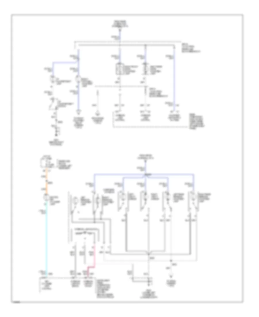
Power Distribution Wiring Diagram (5 of 5) for Oldsmobile Aurora 2003
List of elements for Power Distribution Wiring Diagram (5 of 5) for Oldsmobile Aurora 2003:
- (diagram 4 of 5)
- (in hvac harness, 30 cm from c204 breakout) s221
- A10
- A11
- Abs fuse 10a
- Assembly shift control
- Automatic level control compressor
- Aux pwr fuse 20a
- B10
- B12
- C/ltr fuse 20a
- C11
- C12
- Cigar fuse 40a
- Cigar lighter
- Cigar relay
- Coil
- Console accessory power outlet
- Contact
- D10
- D12
- Driver information center
- E12
- Elc fuse 30a
- Elc relay
- Electronic brake control module
- F/pmp fuse 20a
- F/pmp relay
- From rear fuse block (prk/brk fuse, 20a) (diagram 4 of 5)
- From rear fuse block (rr defog relay) i
- G201 (behind right kick panel)
- G302 (under left side of rear seat cushion)
- Hvac control module
- Hvac fuse 10a
- Ign 3 relay
- Ign 3 rr fuse 10a
- Instrument panel integration module
- Left air temperature actuator
- Mode actuator
- Nca
- Park relay
- Pnk
- Prk lp relay
- Prk/rev fuse 10a
- Rear fuse block (under left rear seat)
- Rear integration module (near upper left corner of rear shelf)
- Recirculation actuator
- Red
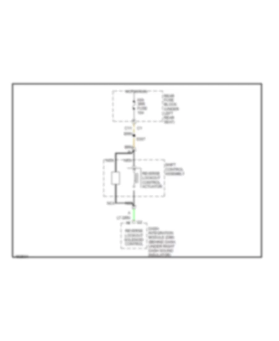
- Reverse lockout control actuator
- Reverse relay
- Right air temperature actuator
- S200 (i/p harness, 15 cm from data link connector)
- S209
- S228 (center console harness, near auxiliary power outlet breakout)
- Underhood fuse block (at right side of engine compartment)
POWER DOOR LOCKS
Power Door Locks Wiring Diagram for Oldsmobile Aurora 2003
List of elements for Power Door Locks Wiring Diagram for Oldsmobile Aurora 2003:
- (in left front door)
- (in right front door)
- Actuator dr
- Ajar
- Battery
- Class 2 data
- Computer data lines system
- Door ajar
- Door open
- Driver door door module
- Driver door lock actuator
- Driver door switch assembly
- Driver power door lock switch
- Drvmdl fuse 10a
- E10
- Front passenger door lock actuator
- Front passenger door module
- G200
- G301
- G302
- Grd
- Ground
- Hot at all times
- Ign sw fuse 15a
- Interior lights system
- Key cyl in
- Key switch
- Left rear door lock actuator
- Left rear door module
- Lock
- Open
- Pass mdl fuse 10a
- Passenger power door lock switch
- Pwr wdo circuit breaker 30a
- Rear fuse block
- Remote function actuator module (below rear shelf)
- Right rear door lock actuator
- Right rear door module
- Rrdr mdl fuse 10a
- S302
- S500
- S604
- Sbi
- Seats system
- Serial data
- Spice pack sp302 (under left rear seat)
- Splice pack sp200 (behind left kick panel)
- Splice pack sp201 (behind right kick panel) g201
- Splice pack sp301 (under right front seat)
- Tan
- Unlock
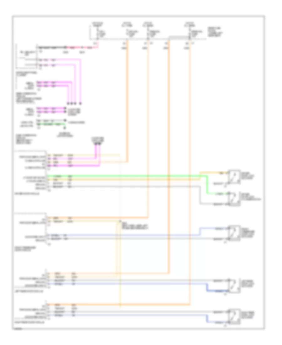
POWER MIRRORS
Power Mirrors Wiring Diagram for Oldsmobile Aurora 2003
List of elements for Power Mirrors Wiring Diagram for Oldsmobile Aurora 2003:
- (behind right kick panel)
- (body harn left side of vehicle, near left power seat breakout)
- (left front door trim harn)
- A7 c3
- B1 c3
- Battery (b+)
- Battery b+
- Bus interface
- Computer data lines system
- D3 c3
- Defogger system (heated mirror)
- Down ctrl
- Driver door lock switch
- Driver door module (ddm)
- Driver door switch asembly
- Drv mdl fuse 10a
- E2 c3
- Exterior lights system
- F2 c3
- Front passenger door module (fpdm)
- G200 (behind left kick panel)
- G201
- G402 (lower left corner of luggage compt)
- Gnd
- Ground
- Heating element
- Horizontal motor
- Hot at all times
- Hot in on and start
- Ign
- Ign 1 fuse 10a
- Inside rear view mirror
- Interior lights system
- Keypad led
- Keypad pwr
- Keypad signal
- L mirror input
- Left
- Left ctrl
- Left mirror
- Left rear door module
- Mirror dn input
- Mirror l input
- Mirror r input
- Mirror up input
- Nca
- Pass mdl fuse 10a
- Pnk
- Pwr wdo circuit breaker 30a
- R mirror input
- Rear fuse block (under left rear seat)
- Reverse lamp relay
- Reverse sig
- Right
- Right ctrl
- Right mirror
- Right rear door module
- S302
- S344
- S500
- Serial data
- Up ctrl
- Vehicle interface unit (viu)
- Vertical motor
POWER SEATS
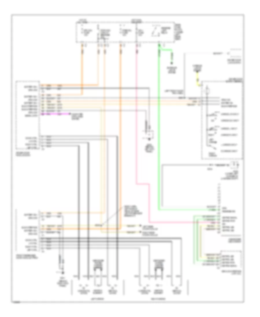
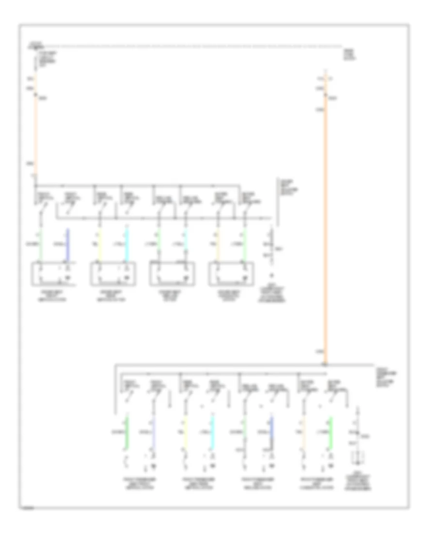
6-Way & Recliner Power Seat Wiring Diagram for Oldsmobile Aurora 2003
List of elements for 6-Way & Recliner Power Seat Wiring Diagram for Oldsmobile Aurora 2003:
- Driver seat adjuster switch
- Driver seat front vertical motor
- Driver seat horizontal motor
- Driver seat rear vertical motor
- Driver seat recline motor
- E12
- Entire seat backward
- Entire seat forward
- F12
- Front passenger seat adjuster switch
- Front passenger seat front vertical motor
- Front passenger seat horizontal motor
- Front passenger seat rear vertical motor
- Front passenger seat recline motor
- Front vertical down
- Front vertical up
- G301 (under right front seat, on forward crossmember)
- Hot at all times
- Nca
- Pwr seat circuit breaker 30a
- Rear fuse block
- Rear vertical down
- Rear vertical up
- Recline backward
- Recline forward
- S321
- S322
- S323
- S325
- Tan
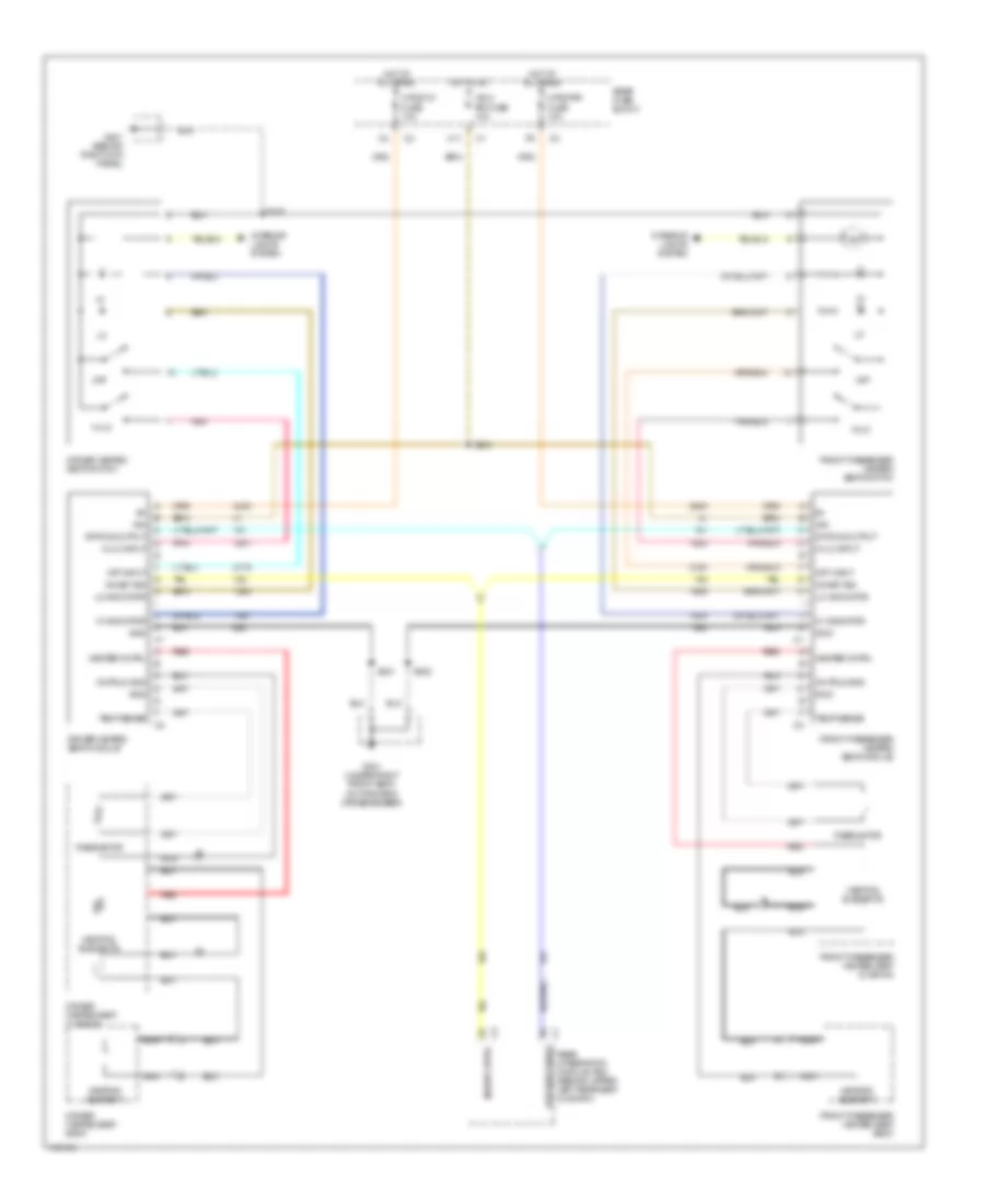
Heated Seats Wiring Diagram for Oldsmobile Aurora 2003
List of elements for Heated Seats Wiring Diagram for Oldsmobile Aurora 2003:
- C11
- Cntrld gnd
- Driver heated seat back
- Driver heated seat cushion
- Driver heated seat module
- Driver heated seat switch
- Front passenger heated seat back
- Front passenger heated seat cushion
- Front passenger heated seat module
- Front passenger heated seat switch
- G201 (behind right kick panel)
- G301 (under right front seat, on forward crossmember)
- Gnd
- Heater cntrl
- Heating element
- Heating elements
- Hi indicator
- Hi/lo
- Hi/lo input
- Hot at all times
- Hot in on
- Htd seat staus
- Htdstlf fuse 10a
- Htdstrf fuse 10a
- Ign
- Ign 3 rr fuse 10a
- Inhibit cntrl
- Inhibit sig
- Interior lights system
- Lo indicator
- Nca
- Off
- Off input
- Pnk
- Rear fuse block
- Rear integration module (rim) (behind upper left rear seat cushion)
- Red
- S228
- S304
- S321
- S322
- Status output
- Temp sense
- Thermistor
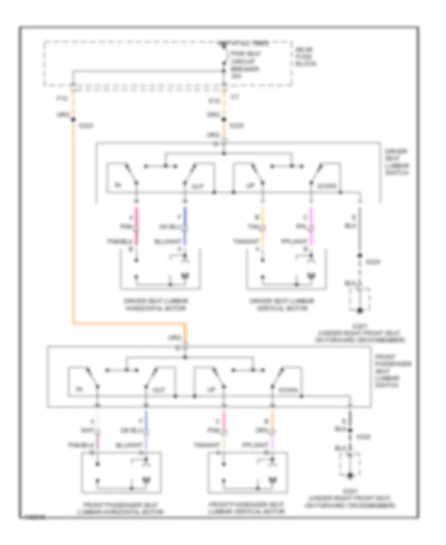
Lumbar Wiring Diagram for Oldsmobile Aurora 2003
List of elements for Lumbar Wiring Diagram for Oldsmobile Aurora 2003:
- Down
- Driver seat lumbar horizontal motor
- Driver seat lumbar switch
- Driver seat lumbar vertical motor
- E12
- F12
- Front passenger seat lumbar horizontal motor
- Front passenger seat lumbar switch
- Front passenger seat lumbar vertical motor
- G301 (under right front seat, on forward crossmember)
- Hot at all times
- Out
- Pnk
- Pwr seat circuit breaker 30a
- Rear fuse block
- S322
- S323
- S324
- S325
- Tan
POWER TOP/SUNROOF
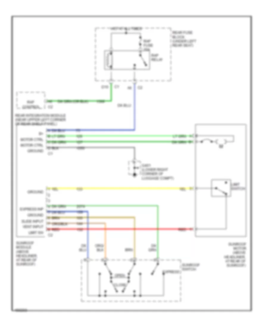
Power Top/Sunroof Wiring Diagram for Oldsmobile Aurora 2003
List of elements for Power Top/Sunroof Wiring Diagram for Oldsmobile Aurora 2003:
- Close
- Control
- D10
- Express
- Express inp
- G401 (lower right corner of luggage compt)
- Ground
- Hot at all times
- Limit sw
- Limit switch
- Motor ctrl
- Open
- Rap
- Rap fuse 20a
- Rap relay
- Rear fuse block (under left rear seat)
- Rear integration module (near upper left corner of rear shelf panel)
- Red
- Slide input
- Sunroof module (above headliner, at rear of sunroof)
- Sunroof motor (above headliner, at rear of sunroof)
- Sunroof switch
- Vent input
POWER WINDOWS
Power Windows Wiring Diagram for Oldsmobile Aurora 2003
List of elements for Power Windows Wiring Diagram for Oldsmobile Aurora 2003:
- (in body harness, left side of vehicle 14.5 cm (5.7 in) from left power seat breakout) s302
- Battery
- Door locks system
- Down
- Down input
- Down signal
- Driver door module (ddm) (in left front door behind trim panel, in upper right corner of door)
- Driver door switch assembly (ddsa)
- Driver window motor (in left front door)
- Drvmdl fuse 10a
- Express down
- Express input
- Front passenger door module (fpdm) (in right front door behind trim panel, in upper left corner of door)
- Front passenger window motor (in right front door)
- Front passenger window switch
- G200 (behind left kick panel)
- G201 (behind right kick panel)
- G301 (under right front seat on forward crossmember)
- G302 (under left side of rear seat cushion)
- Ground
- Hot at all times
- Illum
- Interior lights system
- Left front door) s500
- Left front window
- Left rear door module (lrdm) (in left rear door)
- Left rear window
- Left rear window motor (in left rear door)
- Left rear window switch
- Lockout input
- Memory systems
- Motor down
- Motor up
- Pass mdl fuse 10a
- Pwr wdo circuit breaker 30a
- Rear fuse block (under left rear seat)
- Right front window
- Right rear door module (rrdm) (in right rear door)
- Right rear window
- Right rear window motor (in right rear door)
- Right rear window switch
- Rrdr mdl fuse 10a
- Serial data
- Up input
- Up signal
- Window switches
RADIO
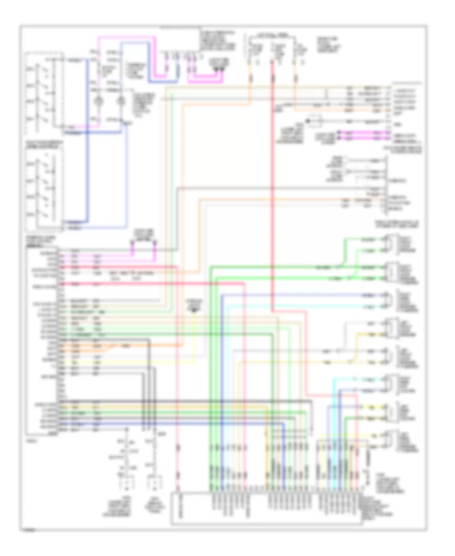
Radio Wiring Diagram, with Amplifier for Oldsmobile Aurora 2003
List of elements for Radio Wiring Diagram, with Amplifier for Oldsmobile Aurora 2003:
- (behind right kick panel)
- (under left front seat, forward of crossmember)
- A10
- A11
- A12
- A13
- A14
- A15
- A16
- Amp sns
- Antenna
- Audio amp fuse 20a
- Audio amplifier (behind right rear seat, below package shelf)
- Audio comm
- Audio fuse 10a
- B10
- B11
- B12
- B13
- B14
- B15
- B16
- Batt
- Battery
- C12 not used
- C200
- C215
- C216
- C430
- Case gnd
- Cd changer-remote playback device
- Cd fuse 10a
- Com audio in
- Computer data lines system
- Dash integration module (dim) (behind dash' under right dash sound insulator)
- Data
- Enable
- Fm comp sig
- Front glass antenna
- G201
- G300
- Gnd
- Grd
- Ground
- Hot at all times
- Ill
- Inflatable restraint steering wheel module coil
- Interior lights system
- L audio in
- L audio out
- Left front door speaker
- Left front door speaker (tweeter)
- Left rear door speaker (tweeter)
- Left rear sub woofer
- Lf spkr
- Lr dr spkr
- Lr spkr
- Lr sub wf
- Nca
- Pnk
- R audio in
- R audio out
- Radio
- Radio antenna module (at rear of headliner)
- Radio on sig
- Rear fuse block (under left rear seat)
- Rear glass antenna
- Red
- Rf spkr
- Right front door speaker
- Right front door speaker (tweeter)
- Right rear door speaker (tweeter)
- Right rear sub woofer
- Right side steering wheel controls
- Rr dr spkr
- Rr spkr
- Rr sub wf
- S209
- S224
- Serial data
- Shield gnd
- Shield grd
- Steering column fuse holder
- Steering wheel hvac control assembly
- Sw1
- Sw2
- Sw3
- Sw4
- Sw5
- Sw6
- Sw7
- Sw8
- Switch fuse 2a
- Swtchd pwr
- Tan
Radio Wiring Diagram, without Amplifier for Oldsmobile Aurora 2003
List of elements for Radio Wiring Diagram, without Amplifier for Oldsmobile Aurora 2003:
- (behind right kick panel)
- (under left front seat, forward of crossmember)
- A10
- A11
- A12
- A13
- A14
- A15
- A16
- Amp sns
- Antenna
- Audio comm
- Audio fuse 10a
- B10
- B11
- B12
- B13
- B14
- B15
- B16
- Batt
- C12 not used
- C200
- C216
- C430
- Case gnd
- Cd changer-remote playback device
- Cd fuse 10a
- Com audio in
- Computer data lines system
- Dash integration module (behind dash, under right dash sound insulator)
- Data
- Enable
- Flat wire
- Fm comp sig
- Front glass antenna
- G203
- G300
- Gnd
- Grd
- Hot at all times
- Ill
- Inflatable restraint steering wheel module coil
- Interior lights system
- L audio in
- L audio out
- Left front door speaker
- Left front tweeter
- Left rear speaker
- Lf spkr
- Lr spkr
- Nca
- R audio in
- R audio out
- Radio
- Radio antenna module (at rear of headliner)
- Rear fuse block (under left rear seat)
- Rear glass antenna
- Red
- Rf spkr
- Right front door speaker
- Right front tweeter
- Right rear speaker
- Right side steering wheel controls
- Rr spkr
- S224
- Serial data
- Shield grd
- Steering column fuse holder
- Steering wheel hvac control assembly
- Sw1
- Sw2
- Sw3
- Sw4
- Sw5
- Sw6
- Sw7
- Sw8
- Switch fuse 2a
- Tan
SHIFT INTERLOCK
Reverse Lockout Wiring Diagram for Oldsmobile Aurora 2003
List of elements for Reverse Lockout Wiring Diagram for Oldsmobile Aurora 2003:
- C11
- Dash integration module (dim) (behind dash, under right dash sound insulator)
- Hot in run
- Ign 3rr fuse 10a
- Nca
- Rear fuse block (under left rear seat)
- Reverse lockout control actuator
- Reverse lockout solenoid control
- S307
- Shift control assembly
Shift Interlock Wiring Diagram for Oldsmobile Aurora 2003
List of elements for Shift Interlock Wiring Diagram for Oldsmobile Aurora 2003:
- 1995 vftc c
- A/t shift lock control solenoid (on shift control assembly)
- A12
- Automatic transaxle
- Automatic transaxle internal mode switch
- B12
- C100
- Computer data lines system
- Data line
- G100 (lower left side of engine)
- G200 (lower left front corner of passenger compt, on right front windshield pillar)
- G201 (lower right front corner of passenger compt, on right front windshield pillar)
- Hot at all times
- Hot in on
- Park relay
- Park relay control
- Powertrain control module (at left side of engine compt, under air cleaner)
- Prk/rev fuse 10a
- Rear fuse block (under left rear seat)
- Rear integration module (near upper left corner of rear shelf panel)
- S225
- S228
- Sig a
- Sig b
- Sig c
- Sig p
- Splice pack sp100
- Splice pack sp200
- Splice pack sp201
- Stoplight switch (on brake pedal bracket)
- W/center console
- W/o center console
STARTING/CHARGING
Charging Wiring Diagram for Oldsmobile Aurora 2003
List of elements for Charging Wiring Diagram for Oldsmobile Aurora 2003:
- (not used) a
- A11
- A12
- B12
- Battery
- Battery positive voltage
- Battery saver active
- Battery volts high
- Battery volts low
- Check charge system
- Computer data lines system
- Dash integration module (dim) (behind dash, under right dash sound insulator)
- Dim fuse 10a
- Driver's information center
- E11
- G305 (under right side of rear seat cushion, near battery)
- Generator
- Ground
- Hot at all times
- Powertrain control module (pcm) (at left side of engine compt, under air cleaner)
- Rear fuse block (under left rear seat)
- Red
- Serial data class 2
- Starter solenoid
- Underhood fuse block (on right side of engine compt)
Starting Wiring Diagram for Oldsmobile Aurora 2003
List of elements for Starting Wiring Diagram for Oldsmobile Aurora 2003:
- Acc
- Battery
- Computer data lines system
- Crank voltage
- G305 (under right side of rear seat cushion, near battery)
- Ground distribution system
- Hold in coil
- Hot in run & start
- Ign sw fuse 15a
- Ignition swtch
- Lock
- Pcm ign fuse 10a
- Powertrain control module (pcm) (at left side of engine compartment, under air cleaner)
- Pull in coil
- Rear fuse block (under left rear seat)
- Run
- Serial data class 2
- Start
- Start 1 relay
- Start circuit breaker 30a
- Starter ctrl
- Starter motor
- Starter solenoid
- Starting/ charging system (charging circuit)
- Underhood fuse block (on right side of engine compt)
- Unlock
SUPPLEMENTAL RESTRAINTS
Supplemental Restraints Wiring Diagram for Oldsmobile Aurora 2003
List of elements for Supplemental Restraints Wiring Diagram for Oldsmobile Aurora 2003:
- A10
- A11
- A12
- A13
- A14
- A15
- A16
- A17
- A18
- Air bag indicator
- Case ground
- Computer data lines system
- Dash integration module (dim) (behind dash, under right dash sound insulator)
- Data link connector (dlc) (partial) (at lower left side of dash)
- G303 (under right front seat, on forward crossmember)
- Ground
- High control
- Hot in run & start
- Ignition
- Inflatable restraint front end discriminating sensor
- Inflatable restraint i/p module
- Inflatable restraint sensing & diagnostic module (sdm) (under center console, mounted to floor pan)
- Inflatable restraint side impact module- left front
- Inflatable restraint side impact module- right front
- Inflatable restraint steering wheel module
- Inflatable restraint steering wheel module coil
- Instrument panel cluster (ipc)
- Left front seat belt switch (closed w/seat belt unbuckled)
- Left inflatable restraint side impact sensor (sis) (at base of left "b" pillar, behind trim)
- Logic
- Low control
- Low reference
- Nca
- Pnk
- Rear fuse block (under left rear seat)
- Right inflatable restraint side impact sensor (sis) (at base of right "b" pillar, behind trim)
- Sensor signal
- Serial data class 2
- Shorting bar
- Signal
- Sir fuse 15a
- Switch signal
- Tan
- Voltage
TRANSMISSION
4.0L VIN C
4.0L VIN C, A/T Wiring Diagram for Oldsmobile Aurora 2003
List of elements for 4.0L VIN C, A/T Wiring Diagram for Oldsmobile Aurora 2003:
- (rear of right cylinder head) engine coolant temperature (ect) sensor
- 1-2 shift sol
- 2-3 shift sol
- 5v ref a
- A/t speed sens
- Acc
- Automatic transaxle
- Automatic transaxle (4t80-e)
- Automatic transaxle fluid pressure manual valve position switch
- Automatic transaxle fluid temperature sensor
- Automatic transaxle input shaft speed sensor
- Automatic transaxle internal mode switch
- Battery
- C2 b1
- C2 b5
- C3 e7
- Class 2 data
- Computer data lines system
- Cruise control system
- Ect sens sig
- G100
- Hot at all times
- Hot in run or start
- Ign 1 fuse 10a
- Ignition
- Ignition key cylinder lamp, driver information center
- Ignition switch
- Instrument cluster
- Instrument cluster, turn siganl switch
- Ip fuse 10a
- Lock
- Malfunction indicator lamp
- Mil cntrl
- Off
- Pcm batt fuse 10a
- Pcm ground
- Pcm ign fuse 10a
- Pnk
- Powertrain control module (pcm) (left side of engine compt, under air cleaner)
- Press ctrl sol
- Pressure control sol
- Rear fuse block (under left rear seat)
- Red
- Run
- S206
- S208
- S216
- Sp100 (on lower left side of engine, near trans- mission)
- Start
- Tan
- Tcc brake sw
- Tcc pwm sol
- Tcc/ cruise release switch
- Tft sensor high
- Tft sensor low
- Throttle position sensor (on throttle body)
- Tp sens grd
- Tp sens sig
- Trans fuse 10a
- Trans range a
- Trans range c
- Trs a input
- Trs b input
- Trs c input
- Trs p input
- Underhood fuse block (right side of engine compt)
- Vehicle speed sensor (vss) (top right side of transmission output housing)
- Vss hi (signal)
- Vss lo (ground)
TRUNK, TAILGATE, FUEL DOOR
Trunk & Fuel Door Release Wiring Diagram for Oldsmobile Aurora 2003
List of elements for Trunk & Fuel Door Release Wiring Diagram for Oldsmobile Aurora 2003:
- A10
- A11
- A12
- Aldl fuse 10a
- B12
- Body fuse 15a
- Class 2 serial data
- Computer data lines system
- Driver door module (ddm)
- Driver door switch assembly (ddsa)
- F/tnkdr rel relay
- Fuel door rel sw
- Fuel door release actuator
- Fuel door release sw
- Fuel door rly ctrl
- G302 (under left side of rear cushion)
- G401 (lower right corner of luggage compartment)
- Garage door opener
- Ground sig
- Hot at all times
- Interior lights system
- Nca
- Near rear compartment courtesy lamp
- Pnk
- Pwr door serial data
- Rear compartment lid release actuator
- Rear fuse block
- Rear integration module (near upper left corner of rear shelf panel)
- S211
- S308
- S420
- Sp302
- Sp401
- Trk rel relay
- Trunk ajar sw
- Trunk ajar sw sig
- Trunk rel rly ctrl
- Trunk rel sw
- Trunk release sw sig
- Valet sw input
- Valet switch
WARNING SYSTEMS
Warning Systems Wiring Diagram for Oldsmobile Aurora 2003
List of elements for Warning Systems Wiring Diagram for Oldsmobile Aurora 2003:
- A11
- A12
- A15
- A16
- Ajar switch
- Auto
- Class 2 serial data
- Computer data lines system
- Dash integration module (dim) (behind dash, under right dash sound insulator)
- Door ajar switch
- Door open sw signal
- Driver door lock actuator
- Driver door module (ddm)
- G200
- G201
- Ground
- Head
- Headlamp switch
- Headlamps on signal
- Ignition switch
- Inflatable restraint sensing & diagnostic module (sdm) (under center console, mounted to floor pan)
- Instrument panel cluster (ipc)
- Instrument panel integration module (ipm) (at center of dash, behind heater & a/c controls)
- Key in ignition signal
- Key-in-ignition switch (closed w/key in ignition)
- Left front seat belt switch (closed w/seat belt unbuckled)
- Left turn lamps
- Logic
- Low reference
- Nca
- Off
- Open switch
- Park
- Park brake switch
- Park lamps on signal
- Powertrain control module (pcm) (at left side of engine compartment, under air cleaner)
- Radio
- Right turn lamps
- S205
- S226
- S250 (in i/p ground harness, 16.5 cm from c210 harness breakout)
- S251 (in i/p ground harness, 10 cm from c210 harness breakout)
- Seat belt sw signal
- Splice pack sp200 (in lower left front corner of passenger compartment, on left front windshield pillar)
- Splice pack sp201 (in lower right corner of passenger compartment, on right front windshield pillar)
- Tan
- Turn signal/hazard flasher module (behind left side of dash, above data link connector)
WIPER/WASHER
Wiper/Washer Wiring Diagram for Oldsmobile Aurora 2003
List of elements for Wiper/Washer Wiring Diagram for Oldsmobile Aurora 2003:
- 150k
- 24,000 ohms
- 270k
- 39k
- 680k
- 82k
- Acc fuse 15a
- Dash integration module (dim) (behind dash, under right dash sound insulator)
- G103 (right side of engine compt, mounted in front of underhood fuse block)
- G106 (near left strut tower, on frame rail)
- G402 (lower left corner of luggage compt)
- Ground
- Headlamps on w/wipers input
- High
- High speed input
- Hot in run & accessory
- Ignition
- Instrument panel cluster
- Low
- Low min
- Max
- Min
- Mist
- Nca
- Off
- Off max
- Outside moisture sensor (w/ rain sense)
- Rain sense sig 1
- Rain sense sig 2
- Red
- S334
- Underhood fuse block (right front side of engine compartment)
- Wash
- Washer switch
- Windshield washer fluid level signal
- Windshield washer fluid level switch (at top of washer solvent container)
- Windshield washer fluid pump (in bottom of washer solvent container)
- Windshield wiper motor (left side of firewall, behind strut)
- Windshield wiper/washer switch
- Wiper fuse 30a
- Wiper speed signal
- Wiper switch