AIR CONDITIONING
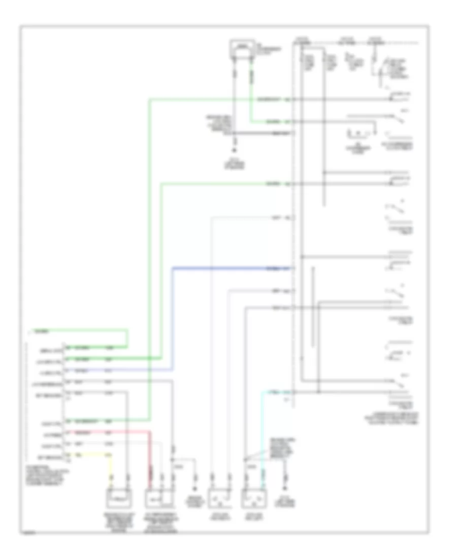
Automatic A/C Wiring Diagram (1 of 2) for Oldsmobile Intrigue GL 2000

List of elements for Automatic A/C Wiring Diagram (1 of 2) for Oldsmobile Intrigue GL 2000:
- (dash harn, 2 cm from radio antenna breakout)
- (dash harn, 2 cm from radio harn breakout)
- (dash harn, 4 cm from radio breakout)
- (right side of dash) g201
- (right side of steering column) sp205
- +5 v
- A/c sol ctrl
- A/c solenoid
- Ambient outside temperature sensor (behind front fasia, mounted to radiator air baffle)
- Battery
- Bi-lev sol ctrl
- Bi-level solenoid
- Blower motor
- Blower motor control module (under right side of dash, in right side of heater-a/c module)
- C10
- C11
- C12
- C13
- C14
- C15
- C16
- Cntrl in
- D10
- D11
- D12
- D13
- D14
- D15
- D16
- Data link connector (under left side of dash, right of steering column)
- Def sol ctrl
- Defrost solenoid
- Fuse block (behind right side of dash)
- Grd
- Ground
- Heater solenoid
- High blower fuse 30a
- Hot at all times
- Hot in run
- Htr sol ctrl
- Hvac control assembly
- Hvac fuse 10a
- Ignition
- Illuminating
- Inside air temperature sensor (behind dash, between the radio & knee bolster)
- Inside temp input
- Interior lights system
- Left air temperature actutor (left side of hvac module)
- Lt elec actuator
- Motor drive
- Nca
- Outside temp input
- Radio-hvac fuse 15a
- Recirc sol ctrl
- Recirc solenoid
- Red
- Right air temperature actutor (right side of hvac module)
- Rt elec actuator
- S202 (dash harn, 8 cm from data link breakout)
- S230
- S231
- S233
- S258
- Sensor ground
- Serial data
- Solid state
- Spd cntrl
- Sun load input
- Sun load temperature sensor (top left of dash)
- Tan
- Vacuum control assembly (on right side of hvac module)
- Volt to blw ctrl
Automatic A/C Wiring Diagram (2 of 2) for Oldsmobile Intrigue GL 2000
List of elements for Automatic A/C Wiring Diagram (2 of 2) for Oldsmobile Intrigue GL 2000:
- (engine harn, 4 cm from coolant fan breakout) s105
- (engine harn, 4 cm from engine fan wiring harn breakout)
- A/c compressor clutch
- A/c clutch fuse 23 10a
- A/c compressor clutch relay
- A/c compressor diode
- A/c press
- A/c refrigerent pressure sensor (left side of engine compt, on accumulator)
- A10
- A11
- C11
- Comp ctrl
- Cool fan 1 fuse 25a
- Cool fan 2 fuse 25a
- Cooling fan (left)
- Cooling fan (right)
- Cooling fan 1 relay
- Cooling fan 2 relay
- Cooling fan 3 relay
- Ect sens grd
- Ect sens sig
- Engine controls system
- Engine coolant temperature (ect) sensor (right rear of engine)
- F12
- G114 (left rear of engine)
- Hi spd ctrl
- Hot at all times
- Ign main relay (closed in run or start)
- Low reference
- Low spd ctrl
- Powertrain control module (pcm) (left front side of engine compt, in air cleaner assembly)
- S105
- S128
- Serial data
- Underhood fuse block (right side of engine compt, mounted to strut tower)
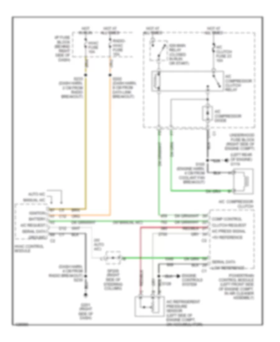
Compressor Wiring Diagram for Oldsmobile Intrigue GL 2000
List of elements for Compressor Wiring Diagram for Oldsmobile Intrigue GL 2000:
- (dash harn, 4 cm from radio breakout) s230
- (left rear of engine) g114
- (w/ auto a/c)
- (w/ manual a/c)
- +5v reference
- A/c compressor clutch
- A/c clutch fuse 23 10a
- A/c compressor clutch relay
- A/c compressor diode
- A/c press signal
- A/c refrigerent pressure sensor (left side of engine compt, on accumulator)
- A/c request
- Auto a/c
- Battery
- C11
- C12
- Clutch request
- Comp control
- D12
- Engine controls system
- G201 (right side of dash)
- Ground
- Hot at all times
- Hot in run
- Hvac control module
- Hvac fuse 10a
- I/p fuse block (behind right side of dash)
- Ign main relay (closed in run or start)
- Ignition
- Low reference
- Manual a/c
- Powertrain control module (left front side of engine compt, in air cleaner assembly)
- Radio- hvac fuse 15a
- S105 (engine harn, 4 cm from coolant fan breakout)
- S128
- S202 (dash harn, 8 cm from data link breakout)
- S233 (dash harn, 2 cm from radio breakout)
- Serail data
- Serial data
- Sp205 (right side of steering column)
- Underhood fuse block (right side of engine compt)
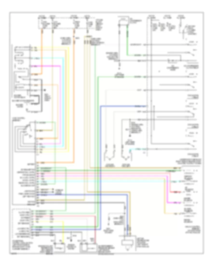
Manual A/C Wiring Diagram for Oldsmobile Intrigue GL 2000
List of elements for Manual A/C Wiring Diagram for Oldsmobile Intrigue GL 2000:
- (dash harn, 8 cm from dlc conn breakout)
- (engine harn, 4 cm from coolant fan breakout) s105
- A/c compressor clutch
- A/c clutch fuse 23 10a
- A/c compressor clutch relay
- A/c compressor diode
- A/c press
- A/c refrigerent pressure sensor (left side of engine compt, on accumulator)
- A/c request sig
- A/c sol cntrl
- A/c solenoid
- A10
- A11
- Battery
- Bi-level solenoid
- Bi-lvl sol cntrl
- Blower motor
- Blower motor relay
- Blower motor resistor
- Blower sw off
- C11
- Clutch req
- Comp ctrl
- Cool fan 1 fuse 25a
- Cool fan 2 fuse 25a
- Cooling fan (left)
- Cooling fan (right)
- Cooling fan 1 relay
- Cooling fan 2 relay
- Cooling fan 3 relay
- Defrost sol cntrl
- Defrost solenoid
- Ect sens grd
- Ect sens sig
- Engine controls system
- Engine coolant temperature (ect) sensor (right rear of engine)
- F12
- G114 (left rear of engine)
- G201 (right side of dash)
- Ground
- Heater solenoid
- Hi spd ctrl
- High blower fuse 30a
- Hot at all times
- Hot in run
- Htr solenoid
- Hvac control assembly
- Hvac fuse 10a
- I/p fuse block (behind right side of dash)
- Ign main relay (closed in run or start)
- Ignition
- Interior lights system
- Lamp dim sig
- Left air temperature actuator (left side of hvac module)
- Left temp act
- Low blower fuse 20a
- Low reference
- Low spd ctrl
- Nca
- Off
- Park lamps on sig
- Powertrain control module (pcm) (left front side of engine compt, in air cleaner assembly)
- Radio hvac fuse 15a
- Recirc sol cntrl
- Recirc solenoid
- Red
- S105 (engine harn, 4 cm from engine fan wiring harn breakout)
- S128
- S202
- S230 (dash harn, 4 cm from radio breakout)
- S233
- Tan
- Underhood fuse block (right side of engine compt, mounted to strut tower)
- Vacuum control assembly (on right side of hvac module)
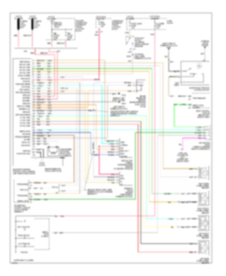
ANTI-LOCK BRAKES
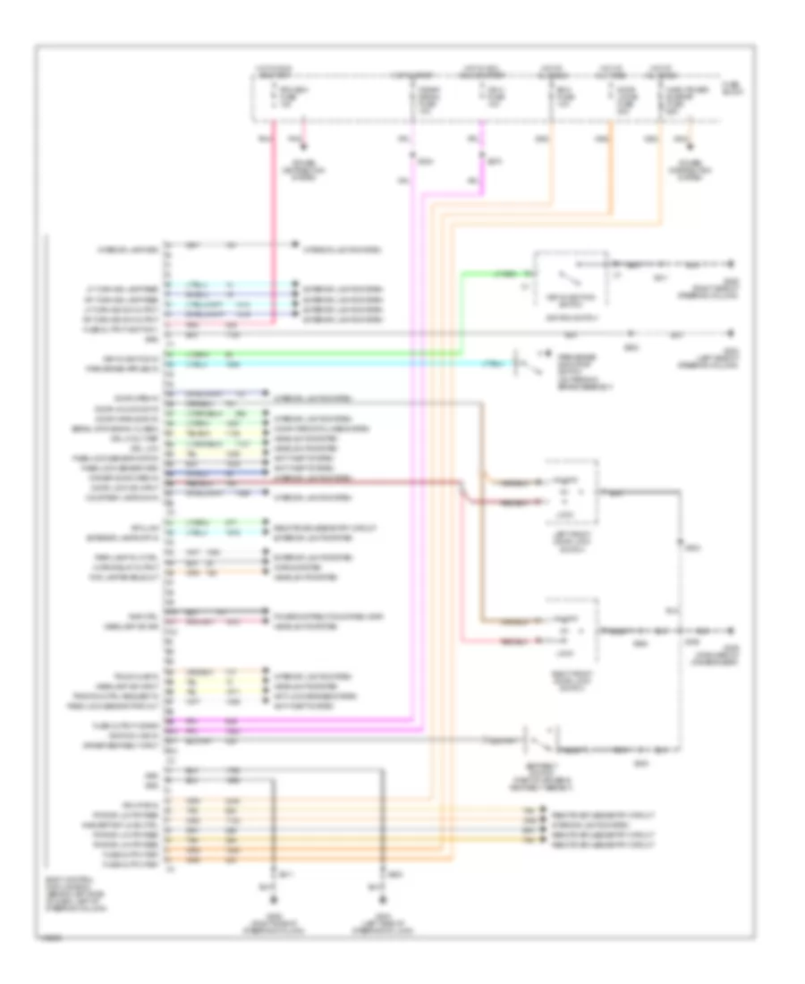
Anti-lock Brake Wiring Diagrams for Oldsmobile Intrigue GL 2000
List of elements for Anti-lock Brake Wiring Diagrams for Oldsmobile Intrigue GL 2000:
- (base of left strut tower)
- (engine wiring harn, near a/c pressure sensor harness breakout)
- (engine wiring harn, near steering column harness breakout)
- (i/p wiring harn, near steering column)
- (jl4)
- (left side of steering column)
- (not used)
- (right side of steering column) g205
- (w/o jl4)
- +5v ref
- Abs fuse 10a
- Abs motor fuse 40a
- Abs valve fuse 20a
- Anti lock ind
- Auxiliary underhood accessory wiring junction block
- B c1
- Battery
- Body control module (behind left side of dash)
- Brake fluid
- Brake pressure modulator valve
- Brake pressure sensor (brake pressure modulator valve)
- Cluster fuse 10a
- Data link connector (dlc) (under left side of dash)
- Electronic brake control module (ebcm) (left side of eng compt)
- Electronic traction control switch
- Fuse block
- G102
- G204
- Grd
- Ground
- Hot at all times
- Hot in run or start
- Ign
- Ignition
- Instrument cluster
- Interior lights system
- Jl4
- Lat accel
- Lateral
- Left front wheel speed sensor
- Left rear wheel speed sensor
- Lf whl spd
- Low trac ind
- Lr whl spd
- Magnasteer actuator (right side of steering gear)
- Msva high
- Msva low
- Nc1
- Nca
- Nf2
- Pcs ind
- Pnk
- Powertrain control module (in air cleaner assembly)
- Pump motor
- Pump mtr ctrl
- Red
- Ref volt
- Ref volt feed
- Remote battery stud
- Rf whl spd
- Right front wheel speed sensor
- Right rear wheel speed sensor
- Rr whl spd
- S183
- S184
- S205
- S211
- S232
- Serial data
- Serial data c1
- Serial data class 2
- Serial data class 2 c2
- Splice pack sp205 (taped in harness, near dlc breakout)
- Steering angle sensor (near base of steering column)
- Stop lamps fuse 15a
- Stop lp feed
- Stoplight switch (on brake pedal support bracket)
- Str angle sens
- Tach out
- Tach sig in
- Tach signal
- Tan
- Test
- Test signal
- Torq delivered
- Torque del c2
- Torque desired
- Torque req c1
- Trac off ind
- Trac request
- Underhood accessory wiring junction block
- Vehicle yaw/ lateral accelerometer sensor (in center console)
- W/o jl4
- Yaw rate
- Yaw sig
ANTI-THEFT
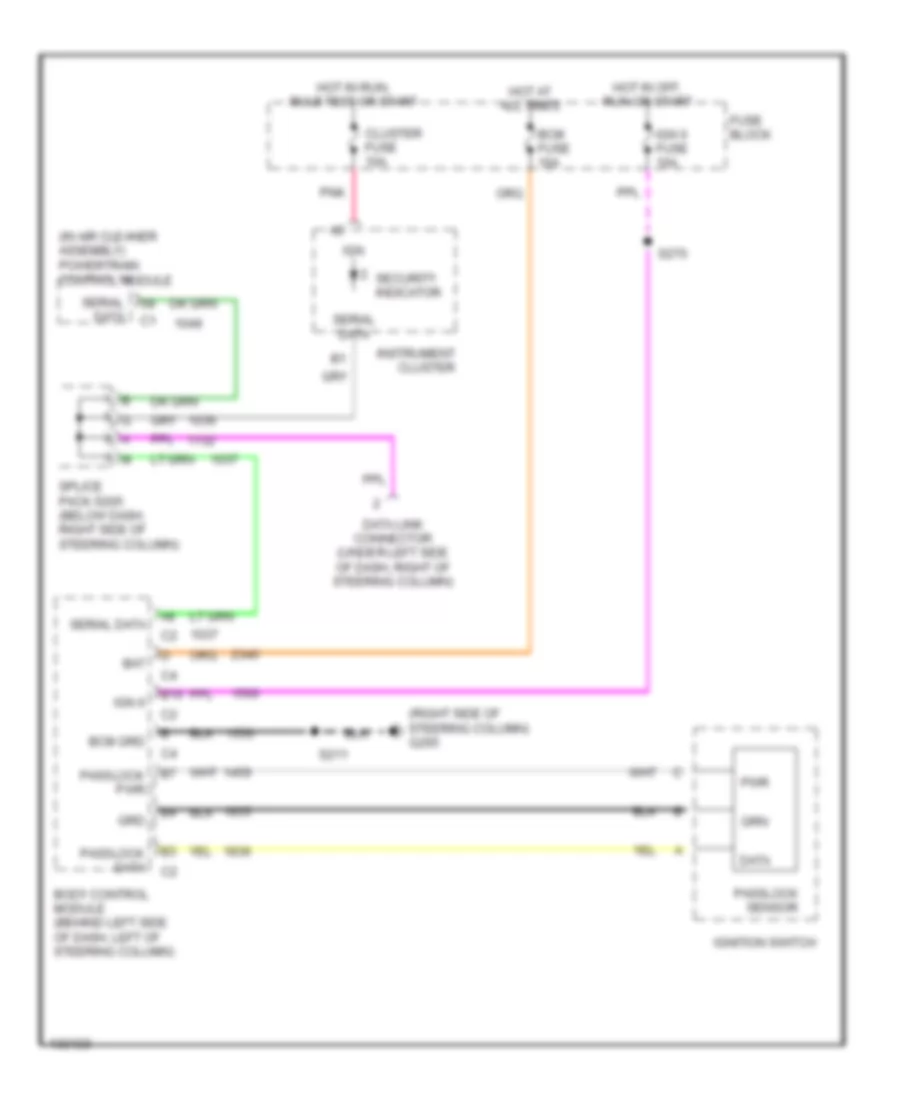
Anti-theft Wiring Diagram for Oldsmobile Intrigue GL 2000
List of elements for Anti-theft Wiring Diagram for Oldsmobile Intrigue GL 2000:
- (in air cleaner assembly) powertrain control module
- (right side of steering column) g205
- B10
- Bat
- Bcm fuse 10a
- Bcm grd
- Body control module (behind left side of dash, left of steering column)
- Cluster fuse 10a
- Data
- Data link connector (under left side of dash, right of steering column)
- Fuse block
- Grd
- Hot at all times
- Hot in off, run or start
- Hot in run, bulb test or start
- Ign
- Ign 0
- Ign 0 fuse 10a
- Ignition switch
- Instrument cluster
- Passlock data
- Passlock pwr
- Passlock sensor
- Pnk
- Pwr
- S211
- S270
- Security indicator
- Serial data
- Splice pack s205 (below dash, right side of steering column)
BODY COMPUTER
Body Computer Wiring Diagrams for Oldsmobile Intrigue GL 2000
List of elements for Body Computer Wiring Diagrams for Oldsmobile Intrigue GL 2000:
- A10
- A11
- A12
- Anti-lock brakes system
- Anti-theft system
- B10
- B11
- B12
- Bcm fuse 10a
- Body control module (bcm) (behind left side of dash, left of steering column)
- Computer data lines system
- Courtesy lamps on in
- Crank signal fuse 10a
- Door handle sw in
- Door lock sw input
- Door locks fuse 20a
- Door open in
- Door unlock sw in
- Driver door open in
- Driver seat belt input
- Drl 5 volt ref
- Drl low
- Exterior lamps off in
- Exterior lights system
- Fog lamp enable out
- Fuse block
- Fuse output-bat
- Fuse output-crank
- Fuse output-ignition 1
- G204 (left side of steering column)
- G205 (right side of steering column)
- G309 (forward of driver's seat)
- Grd
- Headlamp sw input
- Headlamp sw sig
- Headlights system
- Horn relay output
- Horns system
- Hot at all times
- Hot in acc, run or start
- Hot in run or start
- Hot in start
- Ign 0 fuse 10a
- Ignition 0 sig in
- Ignition switch
- Inadv power bus/rap fuse 15a
- Inadvertant load ctrl
- Interior lamp grd
- Interior lights system
- Key-in-ignition in
- Key-in-ignition switch
- Left front door lock switch
- Lf turn sig lamp feed
- Lf turn sig sw output
- Lock
- Nca
- Park brake indicator switch (on parking brake assembly)
- Park lamp rly ctrl
- Pass-lock sensor data in
- Pass-lock sensor grd
- Pass-lock sensor pwr out
- Pcm pwr in
- Pcm-bcm fuse 10a
- Pnk
- Power distribution system
- Power distribution system (rap)
- Pwr dr lk mtr feed
- Rap ctrl
- Remote keyless entry circuit
- Rf turn sig lamp feed
- Rf turn sig sw output
- Rfa link
- Right front door lock switch
- S211
- S234
- S270
- S283
- S303
- S330
- S504
- S604
- Seat belt switch (part of driver's seat belt asembly)
- Serial data signal class 2
- Tan
- Traction ctrl request in
- Trunk ajar in
- Unlock
COMPUTER DATA LINES
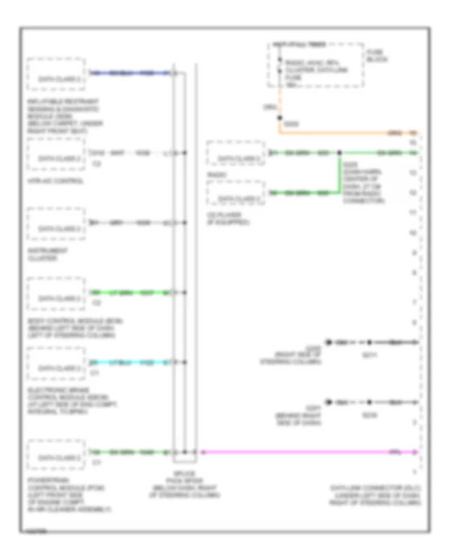
Computer Data Lines for Oldsmobile Intrigue GL 2000
List of elements for Computer Data Lines for Oldsmobile Intrigue GL 2000:
- Body control module (bcm) (behind left side of dash, left of steering column)
- Cd player (if equipped)
- D12
- Data class 2
- Data link connector (dlc) (under left side of dash, right of steering column)
- Electronic brake control module (ebcm) (at left side of eng compt, integral to bpmv)
- Fuse block
- G201 (behind right side of dash)
- G205 (right side of steering column)
- Hot at all times
- Htr-a/c control
- Inflatable restraint sensing & diagnostic module (sdm) (below carpet, under right front seat)
- Instrument cluster
- Powertrain control module (pcm) (left front side of engine compt, in air cleaner assembly)
- Radio
- Radio, hvac, rfa, cluster, data link fuse 15a
- S202
- S211
- S225 (dash harn, center of dash, 27 cm from radio connector)
- S230
- Splice pack sp205 (below dash, right of steering column)
COOLING FAN
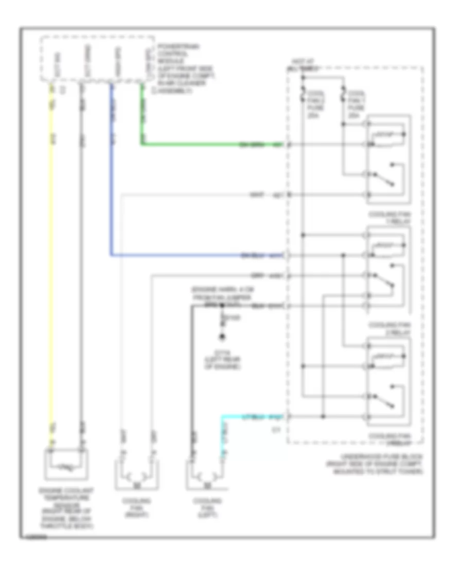
Cooling Fan Wiring Diagram for Oldsmobile Intrigue GL 2000
List of elements for Cooling Fan Wiring Diagram for Oldsmobile Intrigue GL 2000:
- (engine harn, 4 cm from fan jumper breakout)
- A10
- A11
- C11
- Cool fan 1 fuse 25a
- Cool fan 2 fuse 25a
- Cooling fan (left)
- Cooling fan (right)
- Cooling fan 1 relay
- Cooling fan 2 relay
- Cooling fan 3 relay
- Ect sig
- Engine coolant temperature sensor (right rear of engine, below throttle body)
- F12
- G114 (left rear of engine)
- High spd
- Hot at all times
- Low spd
- Powertrain control module (left front side of engine compt, in air cleaner assembly)
- S105
- Underhood fuse block (right side of engine compt, mounted to strut tower)
CRUISE CONTROL
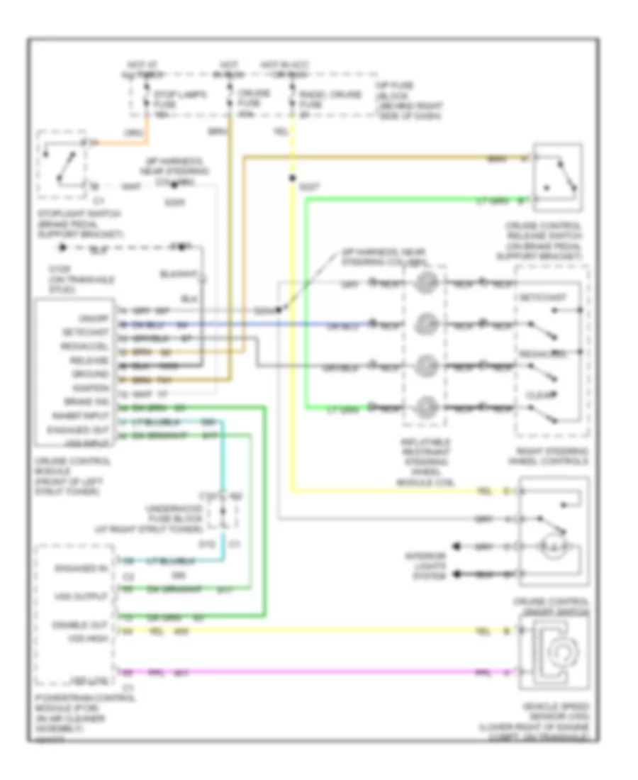
Cruise Control Wiring Diagram for Oldsmobile Intrigue GL 2000
List of elements for Cruise Control Wiring Diagram for Oldsmobile Intrigue GL 2000:
- (i/p harness, near steering column)
- A nca
- All times
- B nca
- Brake sig
- C nca
- C12
- Clear
- Cruise control module (front of left strut tower)
- Cruise control on/off switch
- Cruise control release switch (on brake pedal support bracket)
- Cruise fuse 10a
- D nca
- D12
- Disable out
- Engaged in
- Engaged out
- G129 (on transaxle stud)
- Ground
- Hot
- Hot at
- Hot in acc
- I/p fuse block (behind right side of dash)
- Ignition
- In run
- Inflatable restraint steering wheel module coil
- Inhibit input
- Interior lights system
- Nca
- On/off
- Or run
- Powertrain control module (pcm) (in air cleaner assembly)
- Radio, cruise fuse 2a
- Release
- Res/accel
- Right steering wheel controls
- S106
- S205
- S227
- S294
- Set/coast
- Stop lamps fuse 15a
- Stoplight switch (brake pedal support bracket)
- Underhood fuse block (at right strut tower)
- Vehicle speed sensor (vss) (lower right of engine compt, on transaxle)
- Vss high
- Vss input
- Vss low
- Vss output
DEFOGGERS
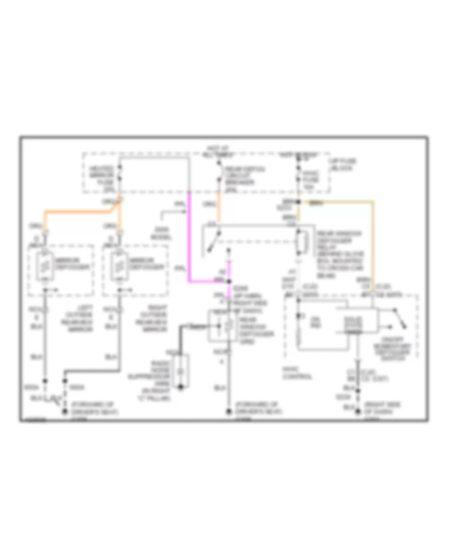
Defogger Wiring Diagram for Oldsmobile Intrigue GL 2000
List of elements for Defogger Wiring Diagram for Oldsmobile Intrigue GL 2000:
- (c67)
- (cj2)
- (forward of driver's seat) g309
- (right side of dash) g201
- C1 (cj2) c2
- C2 b7
- D nca
- Heated mirror fuse 10a
- Hot at all times
- Hot in run
- Hvac control
- Hvac fuse 10a
- I/p fuse block
- Left outside rearview mirror
- Mirror defogger
- Model
- Nca
- On ind
- On/off momentary defogger switch
- Radio noise suppressor wire (in right "c" pillar)
- Rear defog circuit breaker 30a
- Rear window defogger grid
- Rear window defogger relay (behind glove box, mounted to cross-car beam)
- Right outside rearview mirror
- S230
- S233
- S268 (i/p harn, right side of dash) nca
- S504
- S604
- Solid state timer
ELECTRONIC POWER STEERING
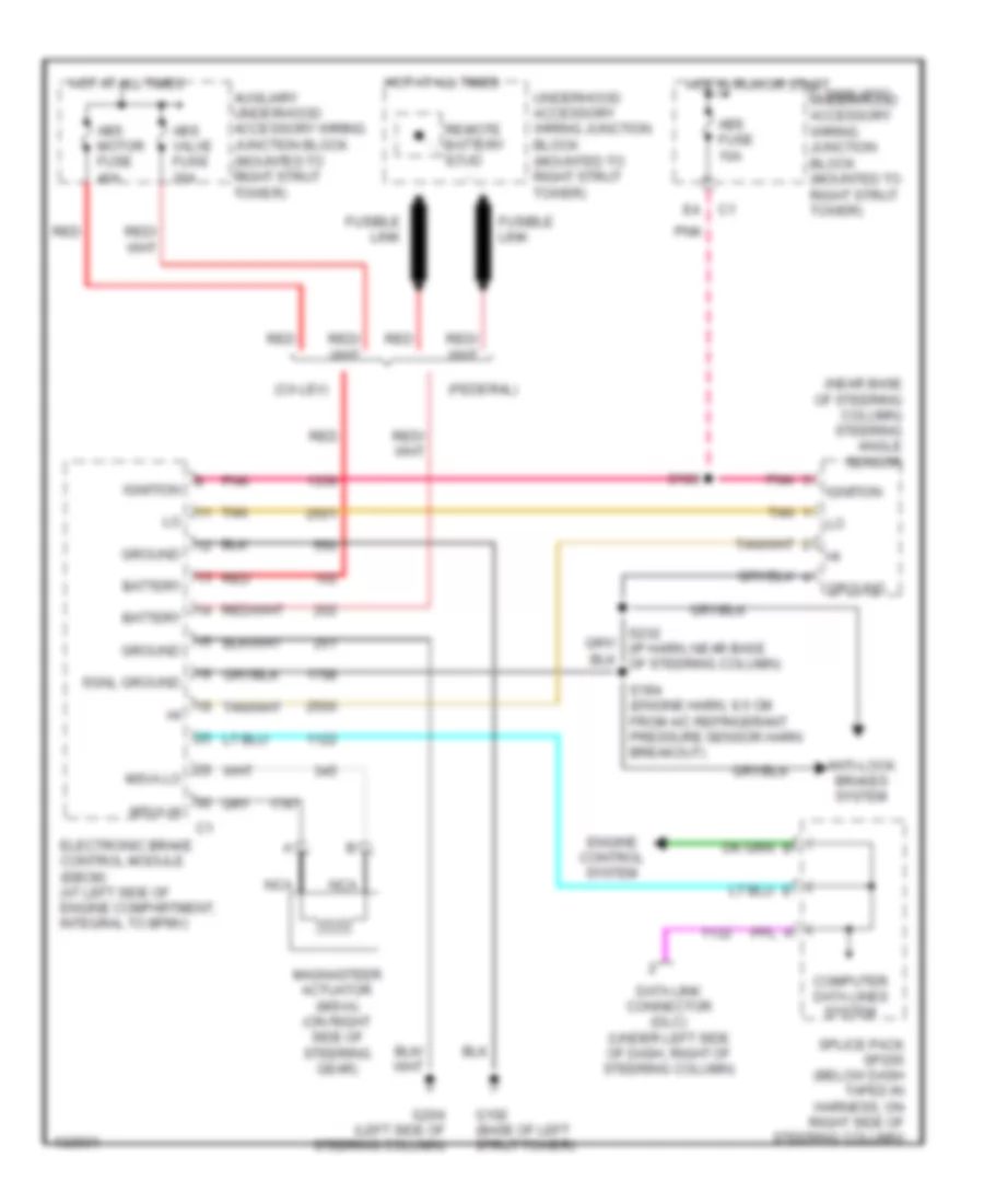
Electronic Power Steering Wiring Diagram for Oldsmobile Intrigue GL 2000
List of elements for Electronic Power Steering Wiring Diagram for Oldsmobile Intrigue GL 2000:
- (ca lev)
- (federal)
- (near base of steering column) steering angle sensor
- 1995 vftc c underhood accessory wiring junction block (mounted to right strut tower)
- Abs fuse 10a
- Abs motor fuse 40a
- Abs valve fuse 20a
- Anti-lock brakes system
- Auxiliary underhood accessory wiring junction block (mounted to right strut tower)
- Battery
- Computer data lines system
- Data link connector (dlc) (under left side of dash, right of steering column)
- Electronic brake control module (ebcm) (at left side of engine compartment, integral to bpmv)
- Engine control system
- Fusible link
- G102 (base of left strut tower)
- G204 (left side of steering column)
- Ground
- Hot at all times
- Hot in run or start
- Ignition
- Magnasteer actuator (msva) (on right side of steering gear)
- Msva hi
- Msva lo
- Nca
- Pnk
- Red
- Remote battery stud
- S183
- S184 (engine harn, 9.5 cm from a/c refrigerant pressure sensor harn breakout)
- Sgnl ground
- Splice pack sp205 (below dash taped in harness, on right side of steering column)
- Tan
- Underhood accessory wiring junction block (mounted to right strut tower)
ENGINE PERFORMANCE
3.5L
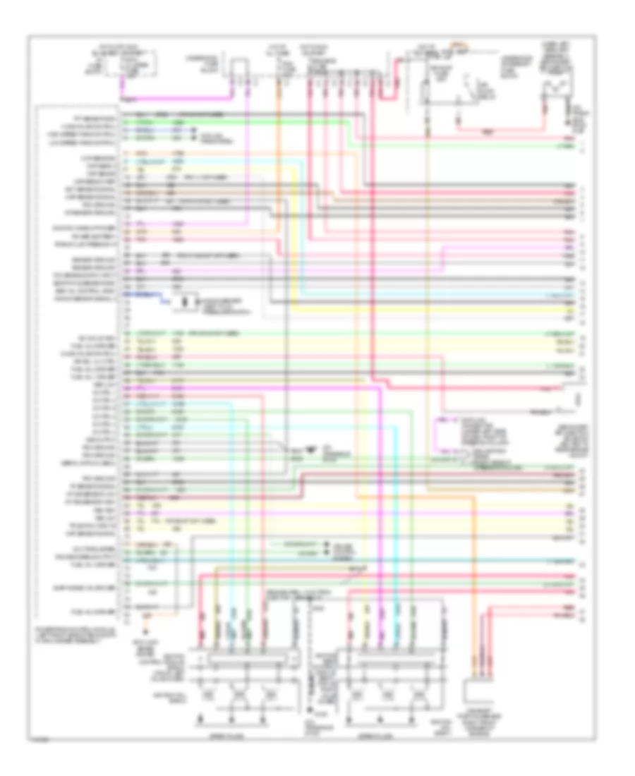
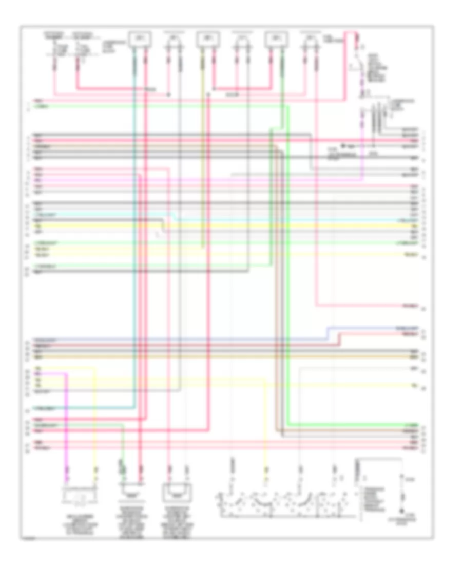
3.5L VIN H, Engine Performance Wiring Diagrams (1 of 4) for Oldsmobile Intrigue GL 2000
List of elements for 3.5L VIN H, Engine Performance Wiring Diagrams (1 of 4) for Oldsmobile Intrigue GL 2000:
- (engine harn, 13 cm from injector 1 breakout)
- (near left headlamp assembly) secondary air injection pump
- (on trans- axle stud) g129
- (on transaxle stud)
- (pin 11 not used)
- (pin 14-15 not used)
- (pin 2-3 not used)
- (pin 21 & 24-27 not used)
- (pin 39-42 not used)
- (pin 66-67 not used)
- 1-2 ss valve control
- 2-3 ss valve control
- A/t iss sensor high
- A/t iss sensor low
- Air pump fuse 50a
- Air pump relay
- Air sol vlv ctrl
- Anti-lock brake system
- B red
- Camshaft position sensor (right front corner of engine)
- Ckp sens a
- Ckp sens b
- Cmp sens sig
- Connector (under left side of dash, right of steering column)
- Cooling fans system
- Cruise control system
- Cruise disable output
- Data link
- Ect sensor signal
- Egr pintle sensor gnd
- Egr val control (gnd)
- Eng emis fuse 10a
- Evap purge val drviver
- Fuel inj 1 driver
- Fuel inj 2 driver
- Fuel inj 4 driver
- Fuel inj 5 driver
- Fuel inj 6 driver
- G129
- High speed fans control
- Hot at all times
- Hot in off, run bulb test, or start
- Hot in run or start
- I/p fuse block
- Iac coil b high
- Iat sensor ground
- Ig ctrl 1
- Ig ctrl 2
- Ig ctrl 3
- Ig ctrl 4
- Ig ctrl 5
- Ig ctrl 6
- Ign 0 cluster fuse 10a
- Ignition bank control module bank 1 (top of right valve cover)
- Ignition coil bank 1
- Ignition coil bank 2
- Ignition control module bank 2 (top of left valve cover)
- Ignition wake up power
- Knock sensor (next to oil pressure switch)
- Knock sensor signal 2
- Low speed fans control
- Maf sensor signal
- Map sens 5v ref
- Map sensor signal
- Pcm fuse 10a
- Pcm ground
- Pnk
- Pnk f
- Power (battery)
- Powertrain control module (left front side of eng compt, in air cleaner assembly)
- Red
- Ref low
- S106
- S108
- S171
- S270
- Secondary air injection solenoid (bolted to rear engine mount)
- Sensor ground
- Serial data (class 2)
- Spark plugs
- Splice pack sp250 (right side of steering column)
- Tcc brake switch input
- Tft sensor gnd
- Tp sensor signal
- Tr switch input b
- Trans fluid press sw a
- Underhood accessory fuse block
- Underhood fuse block
- Vcc torque req
- Vss high
- Vss low
- Vss output
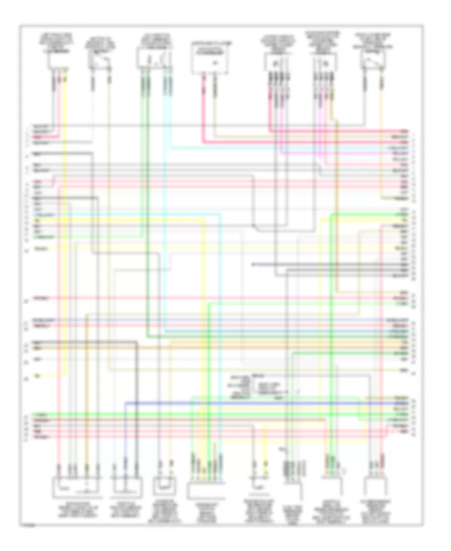
3.5L VIN H, Engine Performance Wiring Diagrams (2 of 4) for Oldsmobile Intrigue GL 2000
List of elements for 3.5L VIN H, Engine Performance Wiring Diagrams (2 of 4) for Oldsmobile Intrigue GL 2000:
- (on transaxle stud)
- Evaporative emissions canister purge solenoid (top left side of eng, near center of valve cover)
- Evaporative emissions canister vent solenoid (behind left side of rear fascia splash shield, in wheelwell)
- F/inj fuse 15a
- F/injr fuse 15a
- Fuel injectors
- G129
- Hot in run or start
- Pnk
- Red
- S106
- S109
- S169
- Stop- light switch (on brake pedal support c2 bracket)
- Transaxle range switch (top right rear of transaxle)
- Underhood fuse block
- Vehicle speed sensor (lower right side of eng compt, on transaxle)
3.5L VIN H, Engine Performance Wiring Diagrams (3 of 4) for Oldsmobile Intrigue GL 2000
List of elements for 3.5L VIN H, Engine Performance Wiring Diagrams (3 of 4) for Oldsmobile Intrigue GL 2000:
- (body harn, front of rear compt)
- (bottom of engine oil pan) engine oil level switch
- (eng harn, near air cleaner, 16 cm from pcm breakout)
- (in exhaust system, behind catalytic converter) heated oxygen sensor (ho2s) 2
- (in right side of exhaust manifold) heated oxygen sensor (ho2s) 1
- (left front side of eng compt, on air cleaner duct) mass air- flow sensor
- (on throttle body assembly) idle air control (iac) valve
- (right lower rear of eng, above transaxle) engine oil pressure switch
- A/c refrigerant pressure sensor (on left side of eng compt, on accumulator)
- Crankshaft position sensor (left side of engine)
- D pnk
- Engine coolant temperature (ect) sensor (right rear of eng, below throttle body)
- Exhaust gas recirculation valve (top rear of eng, near throttle body)
- Fuel tank pressure sensor (in fuel tank)
- Instrument cluster
- Intake air temperature (iat) sensor (left rear of eng compt, in air cleaner duct)
- Malfunction indicator lamp
- Manifold absolute pressure sensor (top right of eng, near throttle body assembly)
- Nca
- Pnk
- Red
- S122
- S409
- Tan
- Throttle position sensor (on throttle body assembly)
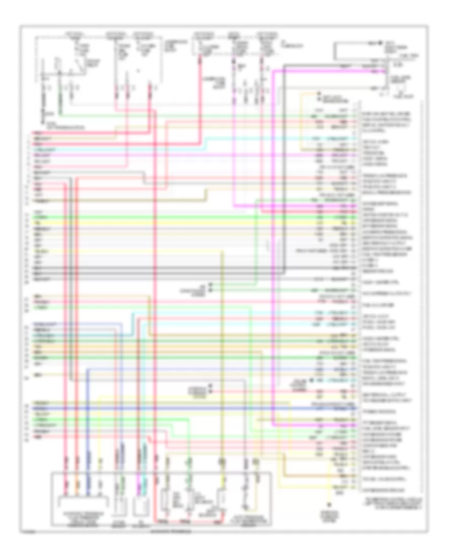
3.5L VIN H, Engine Performance Wiring Diagrams (4 of 4) for Oldsmobile Intrigue GL 2000
List of elements for 3.5L VIN H, Engine Performance Wiring Diagrams (4 of 4) for Oldsmobile Intrigue GL 2000:
- (pin 12-15 not used)
- (pin 20-21 not used)
- (pin 31 not used)
- (pin 40-41 not used)
- (pin 51-54 not used)
- (pin 62 & 64-65 not used)
- (right rear shelf)
- 1-2 shift solenoid
- 2-3 shift solenoid
- 5v ref a
- A/c compress clutch rly
- A/c refrig press signal
- A/c request signal
- A/t iss sensor
- A11
- Air conditioning system
- Air pump relay ctrl
- Anti-lock brake system
- Auto transaxle fluid temperature sensor
- Automatic transaxle
- Automatic transaxle fluid pressure manual valve position switch
- Ckp sensor a gnd
- Ckp sensor a power
- Ckp sensor b ground
- Ckp sensor b power
- Ckp/cmp sens pwr
- Cluster fuse 10a
- Crank
- Crank signal fuse 10a
- Cruise control system
- Cruise engaged input
- D10
- Ect sensor signal
- Egr pintle position 5v ref
- Egr pintle position signal
- Egr val ign positive volt
- Eng oil level ind in
- Eng oil press sensor sig
- Evap can vent sol driver
- F/pmp fuse 15a
- F/pump relay
- Fuel inj 3 driver
- Fuel level sensor
- Fuel level sensor input
- Fuel pump
- Fuel pump relay control
- Fuel tank
- Fuel tank pres sensor
- Fuel tank press signal
- G129 (on transaxle stud)
- G313
- Gen terminal f output
- Gen terminal l output
- Ho2s 1 heater ctrl
- Ho2s 1 signal
- Ho2s 2 heater ctrl
- Ho2s 2 signal
- Hot at all times
- Hot in run or start
- Hot in start
- I/p fuse block
- Iac coil a high
- Iac coil a low
- Iac coil b low
- Iat sensor signal
- Ignition positive volt (2)
- Map sensor signal
- Mil control
- Oxy sen fuse 15a
- Pc sol valve high
- Pc sol valve low
- Pc solenoid
- Pcm- bcm fuse 10a
- Pnk
- Powertrain control module (left front side of eng compt, in air cleaner assembly)
- Red
- Ref lo
- S106
- S234
- Sensor ground
- Starter enable control
- Starting/ charging system
- Tach out
- Tan
- Tcc pwm sol- enoid
- Tcc release switch input
- Tcc sol valve control
- Tft sensor signal
- Torque del
- Tp sens or signal
- Tr switch input a
- Tr switch input c
- Tr switch input d
- Trans abs fuse 10a
- Trans fluid press sw b
- Underhood fuse block
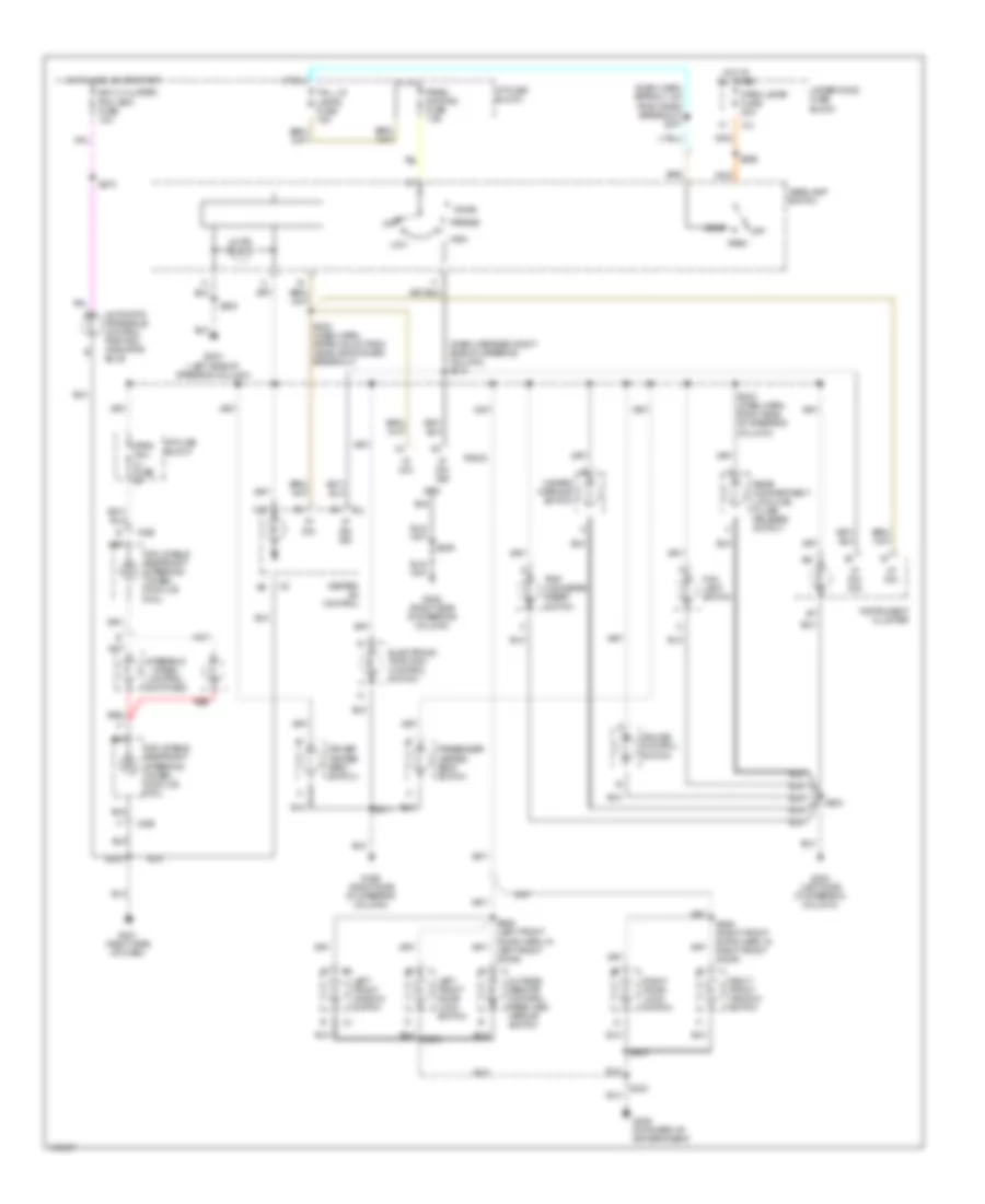
EXTERIOR LIGHTS
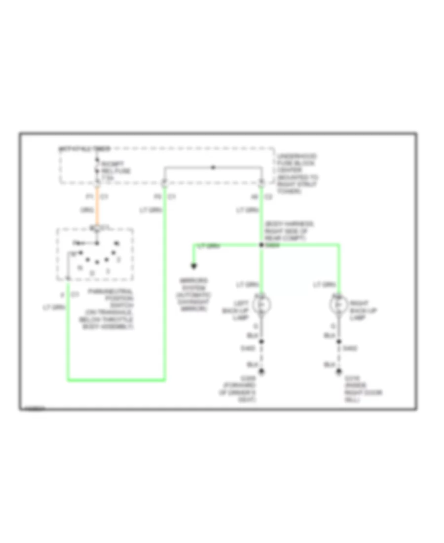
Back-up Lamps Wiring Diagram for Oldsmobile Intrigue GL 2000
List of elements for Back-up Lamps Wiring Diagram for Oldsmobile Intrigue GL 2000:
- (body harness, right side of rear compt) s424
- A6 c2
- C1 f
- F1 c1
- F6 c1
- G309 (forward of driver's seat)
- G316 (inside right door sill)
- Hot at all times
- Left back-up lamp
- Mirrors system (automatic day/night mirror)
- Park/neutral position switch (on transaxle, below throttle body assembly)
- R/cmpt rel fuse 7.5a
- Right back-up lamp
- S402
- S403
- Underhood fuse block center (mounted to right strut tower)
Exterior Lamps Wiring Diagram for Oldsmobile Intrigue GL 2000
List of elements for Exterior Lamps Wiring Diagram for Oldsmobile Intrigue GL 2000:
- (body harness, near breakout to right rear radio speaker)
- (dash harn, near breakout to radio)
- (dash harness, near steering column)
- (left tail lamp wiring harness)
- (not used)
- (on parking brake assembly)
- (rear compt harness, near breakout to license lamps) s419
- A11
- A12 c3
- Ambient light sensor
- Anti-lock brakes system
- B side marker lamp
- B10
- B11
- Body control module (bcm) (behind left side of dash, left of steering column)
- C1 a
- C1 b
- C100
- C2 f12
- Center high mount stop lamp
- Corn- ering lamp
- Cruise control system
- D11
- D12
- Door locks fuse 20a
- Drl ambient light ground ref
- Drl ambient light signal
- Exterior lamp off input
- F11
- Frt park lps fuse 10a
- G109 (right side of front end upper tie bar)
- G204 (left side of steering column)
- G309 (forward of driver seat)
- G316 (inside right door sill)
- Hazard
- Hazard fuse 15a
- Hazard warning switch
- Headlamp
- Headlamp control
- Headlamp relay
- Headlamp switch
- Headlamp switch input
- Headlights system
- Hot at all times
- Hot in run or start
- I/p fuse block (behind right side of dash)
- Instrument cluster
- Interior lights
- Led
- Left
- Left rear side marker lamp
- Left rear turn lamp
- Left right headlamp
- Left tail/ stop lamp
- Left turn indicator
- Lp park fuse 20a
- Marker lamp
- Normal
- Off
- Panel dimming fuse
- Park
- Park brake indicator switch
- Park brake input
- Park lamp relay
- Park lamp relay control
- Park/ a
- Pcm,bcm, u/h relay fuse 10a
- Pnk
- Rear license plate lamps
- Right
- Right rear side marker lamp
- Right rear turn lamp
- Right tail/ stop lamp
- Right turn indicator
- S123
- S205 (dash harness, near steering column)
- S277
- S283
- S291
- S292
- S296
- S402
- S403
- S406
- S408
- S413
- S416
- S417
- S421
- S422
- S430
- S431
- Side b
- Signal lamp
- Stop lamp switch (on brake pedal support bracket)
- Stop lamps fuse 15a
- Tail lamps fuse 15a
- Timer
- Turn signal lamp
- Turn signal switch
- Turn signals fuse 10a
- Underhood fuse block
- Underhood fuse block (mounted to right strut tower)
- W/ spoiler
- W/o spoiler
GROUND DISTRIBUTION
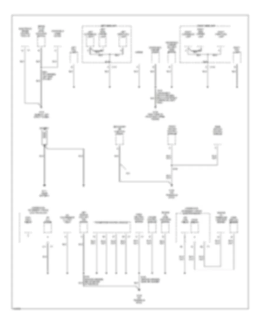
Ground Distribution Wiring Diagram (1 of 3) for Oldsmobile Intrigue GL 2000
List of elements for Ground Distribution Wiring Diagram (1 of 3) for Oldsmobile Intrigue GL 2000:
- A/c clu diode
- A/c compressor clutch coil
- Battery
- Brake fluid level indicator switch
- C11
- C141
- C142
- Cool fan 2 relay
- Cruise control module
- Electronic brake control module
- Engine oil level indicator switch
- Engine oil pressure indicator switch
- F/pmp relay
- Front ignition control module
- G102 (base of left strut tower)
- G109 (right side of front end upper tie bar)
- G111 (near battery)
- G129 (on transaxle stud)
- Horns
- Ign main relay
- Left cornering lamp
- Left engine coolant fan motor
- Left fog lamp
- Left headlamp
- Left park/turn lamp
- Left side marker lamp
- Mass airflow sensor
- Nc1
- Park/ neutral position switch
- Powertrain control module
- Rear ignition control module
- Right cornering lamp
- Right fog lamp
- Right headlamp
- Right park/turn lamp
- Right side marker lamp
- S106 (engine harness, near air ceaner)
- S108
- S123
- S284 (i/p harness, left side of dash)
- Secondary air injection pump
- Underhood accessory wiring junction block
- Washer solvent tank)
- Windshield washer pump
- Windshield washer solvent level switch
- Windshield wiper motor
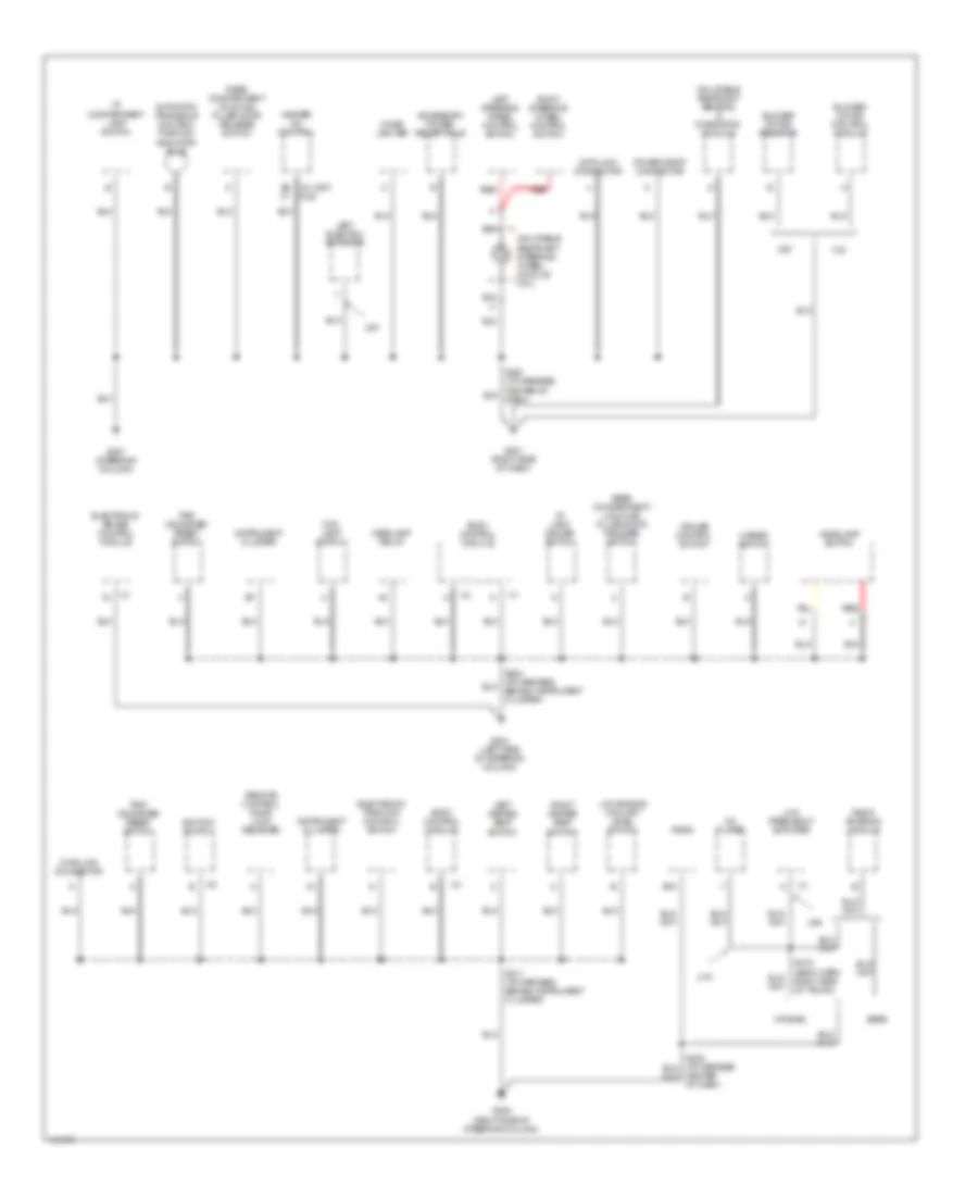
Ground Distribution Wiring Diagram (2 of 3) for Oldsmobile Intrigue GL 2000
List of elements for Ground Distribution Wiring Diagram (2 of 3) for Oldsmobile Intrigue GL 2000:
- u1s
- (c67)
- Accessory power receptacle
- Automatic transaxle control position indicator bulb
- B8 c2 (cj2)
- Base
- Blower motor control module
- Blower motor resistor
- Body control module
- C67
- Cd player
- Center of dash)
- Cigar lighter
- Cj2
- Cruise control switch
- Data link connector
- E16
- Electronic brake control module
- Electronic traction control switch
- Fog lamp switch
- G201 (right side of dash)
- G204 (left side of steering column)
- G205 (right side of steering column)
- G207 (steering column)
- Hazard switch
- Headlamp relay
- Headlamp switch
- Heater a/c control
- I/p compartment lamp switch
- I/p lamp dimmer switch
- Ignition switch
- Inflatable restraint sensing & diagnostic module
- Inflatable restraint steering wheel module coil
- Instrument cluster
- Left electric actuator
- Left heated seat switch
- Left steering wheel control switch
- Low engine coolant level switch
- Low frequency amplifier
- Power drop connector
- Radio
- Radio antenna module
- Rear compartment lid & fuel filler door release switch
- Red
- Remote control door lock receiver
- Right heated seat switch
- Right steering wheel control switch
- S211 (i/p harness behind instrument cluster)
- S418 (body harn right side of trunk)
- Trip odometer reset switch
- U85
- Uplevel
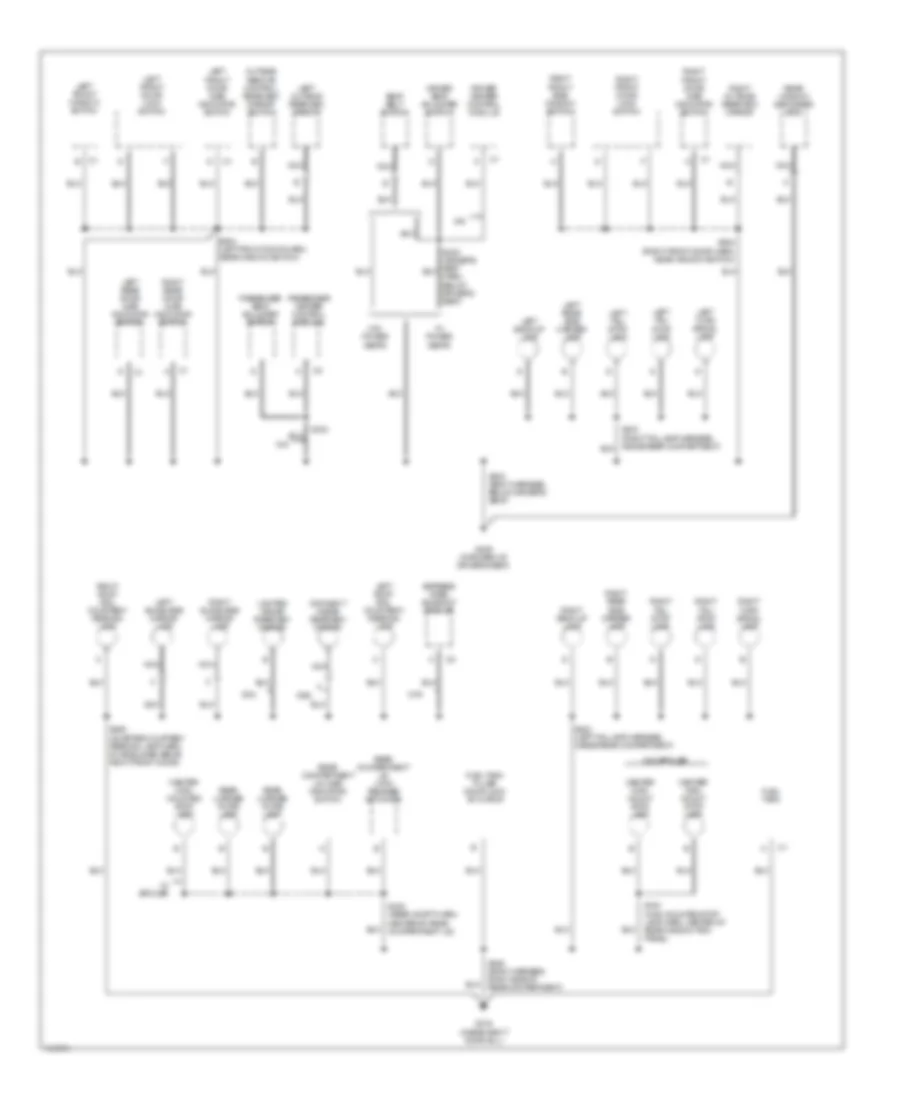
Ground Distribution Wiring Diagram (3 of 3) for Oldsmobile Intrigue GL 2000
List of elements for Ground Distribution Wiring Diagram (3 of 3) for Oldsmobile Intrigue GL 2000:
- Center high mount stop lamp
- Center high mounted stop lamp
- Cf5
- Day/night inside rearview mirror
- Dc4
- Dd8
- Driver heater control module
- Driver seat adjuster switch
- Express open sunroof module
- Fuel tank
- Fuel tank filler door lock actuator
- G309 (forward of driver's seat)
- G316 (inside right door sill)
- Ka1
- Left back-up lamp
- Left front door ajar indicator switch
- Left front door lock switch
- Left front window switch
- Left outside rearview mirror
- Left rear door ajar indicator switch
- Left rear side marker lamp
- Left roof rail courtesy/ reading lamp
- Left sunshade mirror lamp
- Left tail/ stop lamp
- Left turn signal lamp
- Lighted inside rearview mirror
- Nca
- Outside remote control rearview mirror switch
- Passenger heater control module
- Passenger seat adjuster switch
- Rear compartment lid ajar indicator switch
- Rear compartment lid lock release actuator
- Rear license plate lamp
- Rear window defogger grid
- Right back-up lamp
- Right front door ajar indicator switch
- Right front door lock switch
- Right front side window switch
- Right outside rearview mirror
- Right rear door ajar indicator switch
- Right rear side marker lamp
- Right roof rail courtesy/ reading lamp
- Right sunshade mirror lamp
- Right tail/ stop lamp
- Right turn signal lamp
- S303 (body harness, below driver's seat)
- S333
- S385 (quarter courtesy reading lamp harn, in headliner above right front door)
- S402 (left taillamp harness, inside rear compartment)
- S406 (body harness, right side of rear compartment)
- S416 (high mounted stop lamp harn, center of rear window trim panel)
- S430 (rear compt harn, center of rear compartment lid)
- S504 (left front door harn, near window switch)
- S604 (right front door harn, near window switch)
- Seat belt switch
- W/ power seats
- W/ spoiler
- W/o power seats
- W/o spoiler
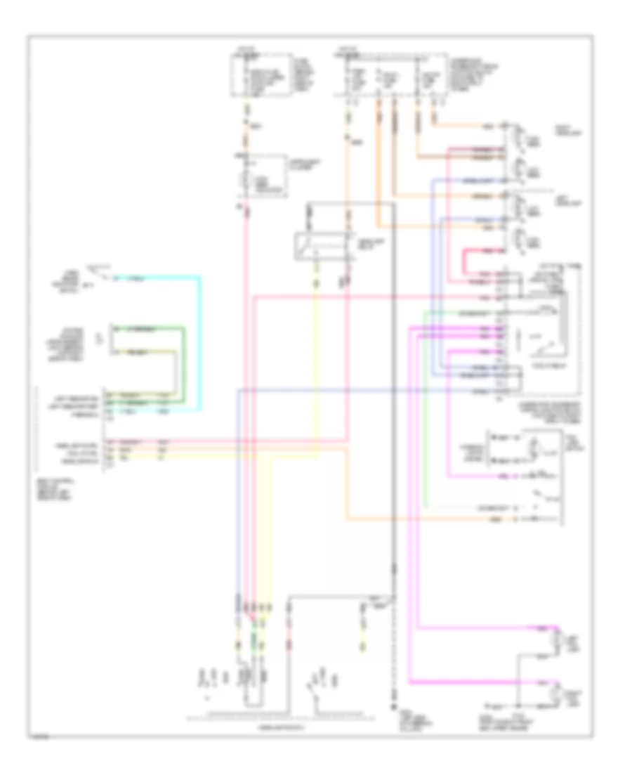
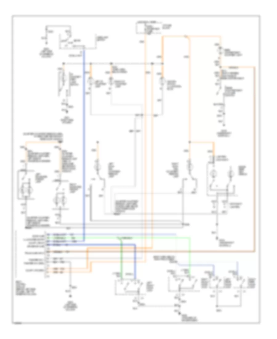
HEADLIGHTS
Headlight Wiring Diagram for Oldsmobile Intrigue GL 2000
List of elements for Headlight Wiring Diagram for Oldsmobile Intrigue GL 2000:
- A10
- A11
- A12
- B2 pnk
- Body control module (behind left side of dash)
- Daytime running lamps ambient light sensor (top right side of dash)
- E11
- E2 c3
- F1 c2
- F10
- Flash
- Fog lamp switch
- Fog lp ctrl
- Fog lp relay
- Frt park lps,fog lps fuse 10a
- Fuse block (behind right side of dash)
- G109 (right side of front end upper tie bar)
- G204 (left side of steering column)
- Hdlp l fuse 15a
- Hdlp r fuse 15a
- Head
- Headlamp cntrl
- Headlamp relay
- Headlamp switch
- Headlamps on
- High
- High beam
- High beam indicator
- Hot at all times
- Illum
- Instrument cluster
- Interior lights system
- Left fog lamp
- Left headlamp
- Light sens grd ref
- Light sensor sig
- Low
- Low beam
- Off
- P-brake in
- Park
- Park brake indicator switch
- Park lps fuse 20a
- Pnk
- Pnk/
- Radio,hvac, rfa,cluster, data link fuse 15a
- Red
- Right fog lamp
- Right headlamp
- S123
- S202
- S269
- S283
- Tan
- Underhood accessory wiring junction block (mounted to right strut tower)
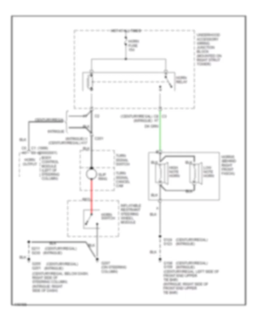
HORN
Horn Wiring Diagram for Oldsmobile Intrigue GL 2000
List of elements for Horn Wiring Diagram for Oldsmobile Intrigue GL 2000:
- (1999) (2000/2001)
- (century/regal)
- (century/regal) (intrigue)
- (century/regal: below dash, right side of steering column)
- (intrigue)
- (intrigue) v (century/regal) a17
- (intrigue: right side of dash)
- Body control module (left of steering column)
- C1 c3
- C201
- C6 a5
- C8 c3
- Century/regal
- G108 g109 (century/regal: left side of front end upper tie bar) (intrigue: right side of front end upper tie bar)
- G205 g201
- G207 (on steering column)
- High note horn
- Horn fuse 15a
- Horn output
- Horn relay
- Horn switch
- Horns (behind right front fascia)
- Hot at all times
- Inflatable restraint steering wheel module
- Intrigue
- Low note horn
- Red
- S124 s123
- S211 s230
- Slip ring
- Turn signal cancel cam
- Turn signal switch
- Underhood accessory wiring junction block (mounted on right strut tower)
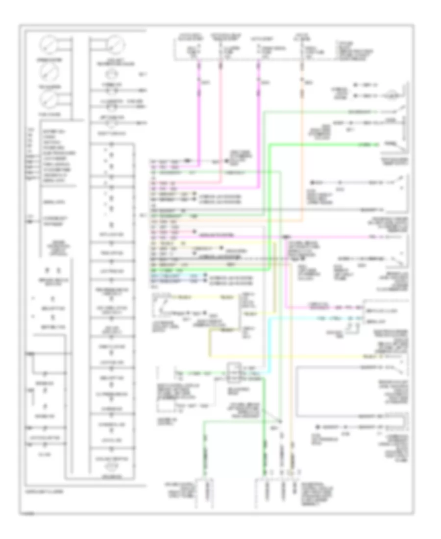
INSTRUMENT CLUSTER
Instrument Cluster Wiring Diagram for Oldsmobile Intrigue GL 2000
List of elements for Instrument Cluster Wiring Diagram for Oldsmobile Intrigue GL 2000:
- (1999 only)
- (1999 w/ 3.8l vin k only)
- (5 bulbs)
- (i/p harn, behind left side of dash, approx 13 cm from grommet)
- (i/p harn, behind left side of dash, approx 8 cm from grommet)
- (right side of steering column)
- (right side of steering column) g205
- 1999 w/ 3.5l vin h & 2000 all
- 1999 w/ 3.8l vin k
- 2000-2001
- A10
- A11
- A12
- Air bag ind
- Anti-lock ind
- B10
- B11
- B12
- Battery (b+)
- Body control module (behind left side of dash, left side of steering column)
- Brake fluid level indicator switch (in brake fluid reservoir)
- Brake ind
- Brk fluid lvl sig
- Change oil ind
- Charge ind
- Cluster fuse 10a
- Coolant temp ind
- Coolant temperature gauge
- Crank
- Crank signal fuse 10a
- Cruise control module (front of left strut tower)
- Cruise ind
- D12
- Driver information display (optional)
- Electronic brake/ traction control module (below left side of dash, left of steering column)
- Electronics grd
- Engine coolant level indicator module (mounted on right side of radiator)
- Exterior lights system
- Fuel gauge
- G102 (base of left strut tower)
- G109 (right side of front end upper tie bar)
- G129 (on transaxle stud)
- G203
- G204 (left side of steering column)
- G205 (right side of steering column)
- Headlights system
- Heater-a/c control
- Hi beam ind
- Hot at all times
- Hot in accy, run or start
- Hot in run, bulb test or start
- Hot in start
- I/p fuse block (behind right side of dash, in right door opening)
- Ign 0 fuse 10a
- Ignition 0
- Illumination
- Instrument cluster
- Interior lights system
- Left turn ind
- Low coolant ind
- Low engine coolant level switch
- Low fuel ind
- Low oil ind
- Low trac ind
- Low washer
- Mil ind
- Mode
- Mode select
- Oil pressure ind
- Park lamps on
- Pnk
- Power grd
- Powertrain control module (left front side of engine compt, in air cleaner assembly)
- Radio- hvac fuse 15a
- Reset
- Right turn ind
- S106
- S123
- S202
- S211
- S234
- S270
- S281
- S283
- S284
- S286
- Seat belt ind
- Security ind
- Serial dat
- Serial data
- Service vehicle soon ind
- Speedometer
- Splice pack sp205
- Srs system
- Tachometer
- Tire pressure ind (1999 only)
- Trac off ind
- Trip odometer reset switch
- Trip reset
- Underhood accessory wiring junction block (mounted to right strut tower)
- Vdc ind (2000 only)
- Vdc warm-up ind (2000 only)
- Vf dimmer feed
- Vss signal in
- Wash fluid ind
- Windshield washer solvent level switch (in washer fluid reservoir)
INTERIOR LIGHTS
Courtesy Lamps Wiring Diagram for Oldsmobile Intrigue GL 2000
List of elements for Courtesy Lamps Wiring Diagram for Oldsmobile Intrigue GL 2000:
- (body harn, below right front seat) s322
- (day-night)
- (lighted)
- (quarter courtesy reading harn, in headliner above right rear door window) s386
- (quarter courtesy reading lamp harn, in headliner above right rear door window) s387
- (quarter courtesy reading lamp harn, left side of windshield header) s383
- Body control module (behind left side of dash, left of steering column)
- Court lps (grd)
- Court lps on
- Dome
- Door ajar
- Driver dr ajar
- G201 (right side of dash)
- G204 (left side of steering column)
- G309 (forward of driver's seat)
- G316 (inside right door sill)
- Headlamp switch
- Hot at all times
- I/p compart- ment lamp switch
- I/p fuse block
- Ignition switch illumination bulb
- Illuminated entry
- Inadv power bus fuse 15a
- Inside rear view mirror
- Left front door lock
- Left i/p courtesy lamp
- Left rear door lock
- Left roof rail courtesy/ reading lamp
- Left sunshade mirror lamp
- Nca
- Off
- Rear compartment courtesy lamp
- Rear compartment lid ajar switch
- Right front door lock
- Right i/p courtesy lamp
- Right rear door lock
- Right roof rail courtesy/ reading lamp
- Right sunshade mirror lamp
- S230
- S271
- S283
- S303
- S385
- S430
- S504
- S604
- Theater dim (grd)
- Theater dim 1
- Trunk ajar input
Instrument Illumination Wiring Diagram for Oldsmobile Intrigue GL 2000
List of elements for Instrument Illumination Wiring Diagram for Oldsmobile Intrigue GL 2000:
- (dash harn, approx 1 cm from radio breakout) s277
- (dash harness, right side of steering column) s212
- Automatic transaxle control position indicator bulb
- C16
- C205
- Cruise control switch
- Dome
- Driver heated seat switch
- E16
- Electronic traction control switch
- Fog lamp switch
- G201 (right side of dash)
- G204 (left side of steering column)
- G205 (right side of steering column)
- G309 (forward of driver's seat)
- Grd
- Hazard warning switch
- Head
- Headlamp switch
- Heater- a/c control
- High
- Hot at all times
- Hot in acc, on or start
- I/p fuse block
- Ign 0, cluster pcm, bcm fuse 10a
- Illum
- Inflatable restraint steering wheel module coil
- Instrument cluster
- Left front door lock switch
- Left front window switch
- Low
- Off
- Outside remote control rear view mirror switch
- Panel dimming fuse 7.5a
- Parade
- Park
- Park lamps fuse 20a
- Passenger heated seat switch
- Radio
- Rear compartment lid & fuel filler release switch
- Red
- Right door lock switch
- Right front window switch
- S203 (dash harn, right side of steering column)
- S211
- S222 (dash harn, approx 6 cm from headlamp dimmer breakout)
- S230
- S239
- S270
- S283
- S296
- S303
- S506 (left front door harn, in left front door)
- S604
- S606 (right front door harn, in right front door)
- Steering wheel control switches
- Strg whl ill fuse 2a
- Tail, lic lamps fuse 15a
- Trip odometer reset switch
- Underhood fuse block
- Vf dim
- Vf dim sig
POWER DISTRIBUTION
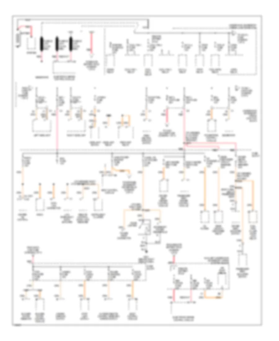
Power Distribution Wiring Diagram (1 of 3) for Oldsmobile Intrigue GL 2000
List of elements for Power Distribution Wiring Diagram (1 of 3) for Oldsmobile Intrigue GL 2000:
- (body harn, below passenger seat)
- (c67)
- (i/p harn, right side of dash)
- (i/p harness, 21 cm from bulkhead grommet) s275
- (i/p harness, right of steering column)
- A/c clu fuse 10a
- A/c clu relay
- A12
- Abs motor fuse 40a
- Abs valve fuse 20a
- Accessory power receptacle
- Air pump fuse 10a
- Air pump relay
- Auxiliary underhood accessory wiring junction block
- Bat 1 maxi fuse 60a
- Bat 2 maxi fuse 60a
- Bat 3 maxi fuse 60a
- Battery
- Bcm fuse 10a
- Blower motor control module
- Blower motor resistor
- Body control module
- C2 a1 c12 (cj2)
- C67
- Cd changer fuse 10a
- Cd player
- Cigar lighter
- Cigar ltr aux power fuse 20a
- Cj2
- Cool fan 1 fuse 25a
- Cool fan 1 relay
- Cool fan 2 fuse 25a
- Cool fan 2 relay
- Cool fan 3 relay
- Crank relay
- Data link connector
- Door locks fuse 20a
- Driver seat adjuster switch
- Driver seat heater control module
- Ecm fuse 10a
- Electronic brake control module
- F/pmp fuse 15a
- F/pmp relay
- Fog lamps relay
- Fog lp fuse 10a
- From a horn fuse (diagram 1 of 3)
- From bat 2 maxi fuse (diagram 1 of 3)
- From remote battery stud (diagram 1 of 3)
- Fuel tank filler door lock relay
- Fuse block
- Fusible link (10 ga- red)
- Fusible link (16 ga- red)
- G201 (behind right side of dash)
- Gen fuse 10a
- Generator
- Hazard fuse 15a
- Hazard warning switch
- Hdlp l fuse 15a
- Hdlp r fuse 15a
- Headlamp relay
- Headlamp switch
- Heater- a/c control
- High blower fuse 30a
- Horn fuse 15a
- Horn relay
- Inadv power bus/rap fuse 15a
- Instrument cluster
- Left headlamp
- Left heated seat fuse 15a
- Low frequency audio amplifier
- Lp park fuse 20a
- Nc2
- Nca
- Nf2
- Outside remote control rearview mirror switch
- Park/ neutral position switch
- Parklamp relay
- Passenger seat adjuster switch
- Passenger seat heater control module
- Power drop connector
- Power mirrors fuse 2a
- Power seats circuit breaker 30a
- Powertrain control module
- R/cmpt rel fuse 7.5a
- Radio
- Radio- hvac fuse 15a
- Rear defogger circuit breaker 30a
- Rear window defogger relay
- Red
- Remote battery stud
- Remote control door lock receiver
- Right headlamp
- Right heated seat fuse 15a
- S202
- S230
- S293
- S296
- Starter
- Starter sloenoid fuse 40a
- Stop lamp switch
- Stop lamps fuse 15a
- To hdlp l fuse (diagram 1 of 3)
- To high blower fuse (diagram 1 of 3)
- To ign 1 maxi fuse (diagram 2 of 3)
- To remote battery stud (diagram 1 of 3)
- To retained accessory power relay (diagram 2 of 3)
- Underhood accessory wiring junction block
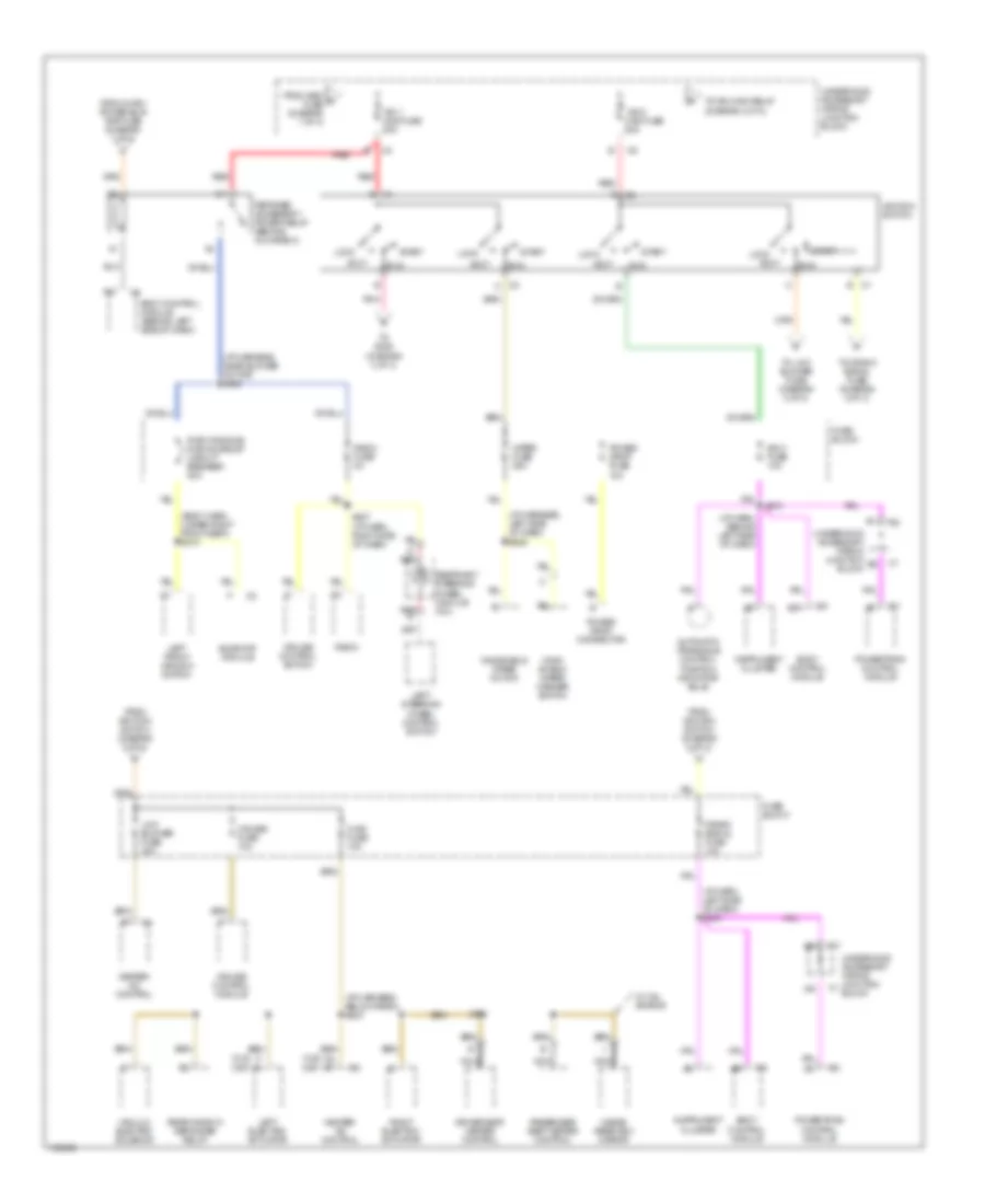
Power Distribution Wiring Diagram (2 of 3) for Oldsmobile Intrigue GL 2000
List of elements for Power Distribution Wiring Diagram (2 of 3) for Oldsmobile Intrigue GL 2000:
- (body harn, under right front seat) s310
- (cj2) (c67)
- (i/p harn, behind left side of dash)
- (i/p harn, left side of dash) s234
- (i/p harness, below radio) s233
- (i/p harness, left side of dash) s249
- (i/p harness, near blower motor) s263
- A10
- Accy
- Automatic transaxle control position indicator bulb
- B10
- Body control module
- Body control module (behind left side of dash)
- C1 b
- C2 c
- C5 b7
- Crank signal fuse 10a
- Cruise control module
- Cruise control switch
- Cruise fuse 10a
- Driver seat heater control
- From gen d fuse (diagram 1 of 3)
- From ignition switch (diagram 2 of 3)
- From inadv power bus/ rap fuse (diagram 1 of 3)
- Fuse block
- G red
- Heater- a/c control
- Hvac fuse 10a
- Ign 0 fuse 10a
- Ign 1 maxi fuse 50a
- Ign 2 maxi fuse 50a
- Ignition switch
- Inside rearview mirror
- Instrument cluster
- Left electric actuator
- Left front window switch
- Left steering wheel control switch
- Lock
- Low blower fuse 20a
- Nca
- Passenger seat heater control
- Pnk
- Power drop connector
- Power drop fuse 10a
- Powertrain control module
- Pwr windows pwr sunroof circuit breaker 30a
- Radio
- Radio fuse 2a
- Rear window defogger relay
- Red
- Red g
- Restraint steering wheel module coil
- Retained accessory power relay (behind glove box)
- Right electric actuator
- Run
- S227 (i/p harn, right side of dash)
- S270
- S323
- Start
- Sunroof module
- To crank signal fuse (diagram 2 of 3)
- To ign main relay (diagram 3 of 3)
- To low blower fuse (diagram 2 of 3)
- To s228 (diagram 3 of 3)
- Underhood accessory wiring junction block
- Vacuum electric solenoid
- W/ 3.5l engine
- Wind- shield wiper/ washer switch
- Windshield wiper motor
- Wiper fuse 25a
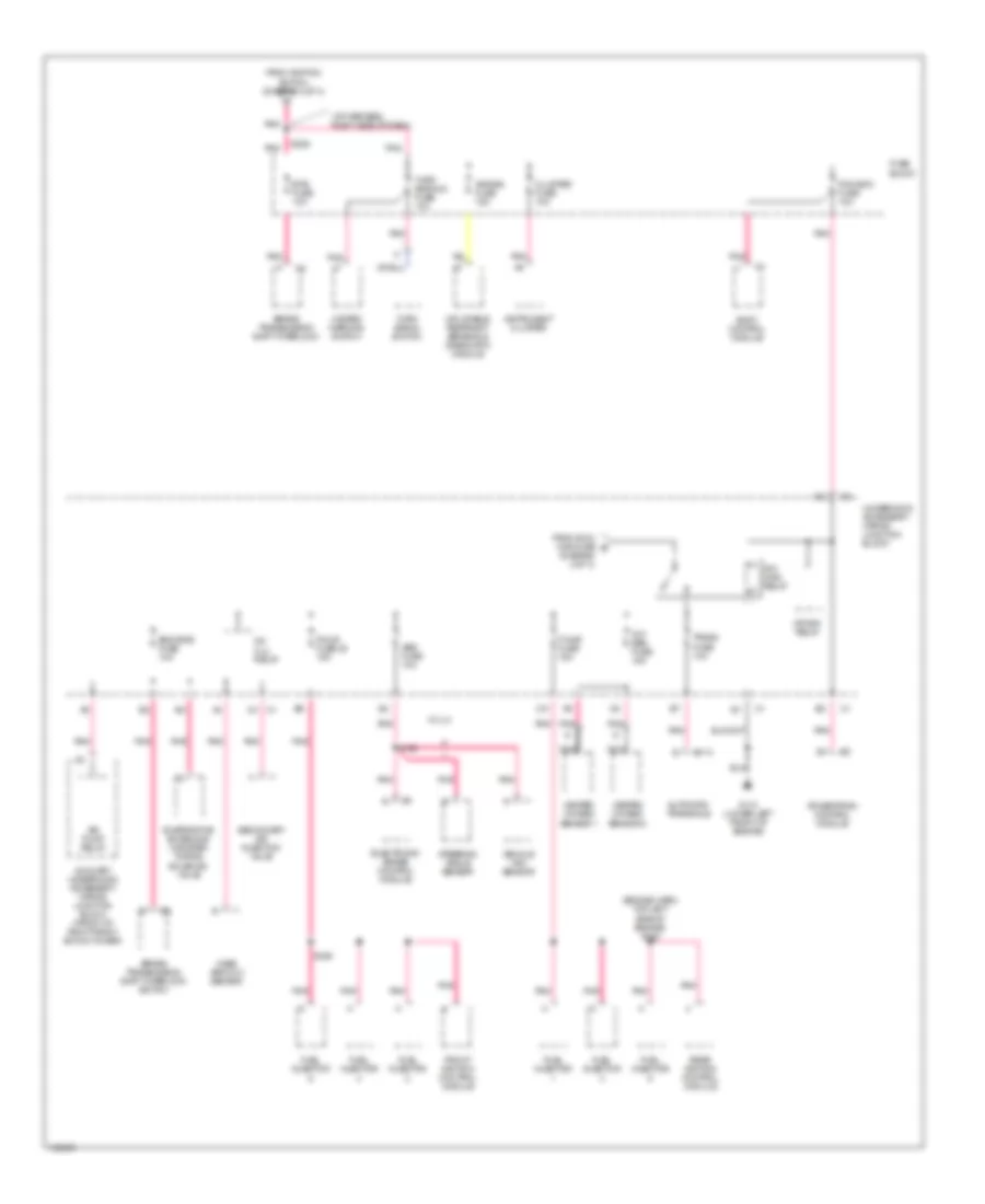
Power Distribution Wiring Diagram (3 of 3) for Oldsmobile Intrigue GL 2000
List of elements for Power Distribution Wiring Diagram (3 of 3) for Oldsmobile Intrigue GL 2000:
- (diagram 2 of 3)
- (engine harn, top left side of engine) s109
- (i/p harness, right side of dash)
- A/c clu relay
- Abs fuse 10a
- Air bag fuse 15a
- Air pump relay
- Automatic transaxle
- Auxiliary underhood accessory wiring junction block (front of right front shock tower)
- Body control module
- Brake transmission shift interlock
- Brake transmission shift interlock switch
- Btsi fuse 10a
- C113
- Cluster fuse 10a
- Crank relay
- Electronic brake control module
- Eng emis fuse 10a
- Evaporative emissions canister purge solenoid valve
- F/injr fuse 15a
- F/injr fuse 25 15a
- From ign 2 maxi fuse e
- From ignition switch (diagram 2 of 3)
- Front ignition control module
- Fuel injector
- Fuse block
- G110 (lower left front of engine)
- Hazard warning switch
- Heated oxygen sensor 1
- Heated oxygen sensor 2
- Ign main relay
- Inflatable restraint sensing & diagnostic module
- Instrument cluster
- Mass airflow sensor
- Nca
- Oxy sen fuse 15a
- Pcm-bcm fuse 10a
- Pnk
- Powertrain control module
- Rear ignition control module
- S169
- S183
- S228
- Secondary air injection valve
- Steering angle sensor
- Trans fuse 10a
- Turn signal switch
- Turn signals fuse 10a
- Underhood accessory wiring junction block
- Vehicle yaw sensor
- W/ jl4
POWER DOOR LOCKS
Power Door Lock Wiring Diagram for Oldsmobile Intrigue GL 2000
List of elements for Power Door Lock Wiring Diagram for Oldsmobile Intrigue GL 2000:
- (body harn, center floor on left side of tunnel) s315
- (body harness, below right door speaker, 44cm from power door breakout) s314
- (century,regal)
- (intrigue)
- 2001 intrigue
- All drs lock
- Battery
- Battery (b+)
- Bcm fuse 10a (intrigue)
- Bcm pwr fuse 10a (century, regal)
- Body control module (behind left side of dash, left of steering column)
- Door lock fuse 20a
- Dr lock sw in
- Dr unlk sw in
- Driver dr unlk
- Except 2001 intrigue
- G204 (left side of steering column)
- G205 (right side of steering column)
- G309 (forward of driver's seat)
- G309 (left front door sill)
- Ground
- Hot at all times
- I/p fuse block (behind right of dash in right door opening)
- Interior lights system
- Left front door lock
- Left front door lock switch
- Left rear door lock
- Lock
- Pass drs unlk
- Radio, hvac, cluster, cel tel fuse 15a (century, regal)
- Radio, hvac, cluster, data line fuse 15a (intrigue)
- Remote control door lock receiver (rke) (left side of dash, on right side of instrument cluster)
- Rfa link
- Right front door lock
- Right front door lock switch
- Right rear door lock
- S202
- S211
- S269
- S283
- S303
- S504
- Tan
- Trunk lid rel
- Trunk/ tailgate/ fuel doors system
- Unlock
POWER MIRRORS
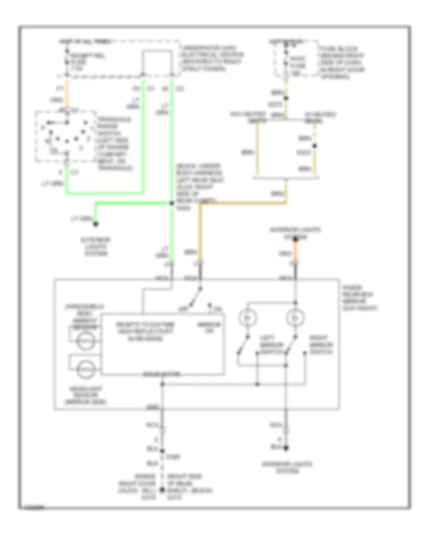
Electrochromic Mirror Wiring Diagram for Oldsmobile Intrigue GL 2000
List of elements for Electrochromic Mirror Wiring Diagram for Oldsmobile Intrigue GL 2000:
- (buick)
- (buick: under body harness, left rear seat, olds: right side of rear compt) s424
- (inside right door sill) g316
- (olds)
- (right side of rear shelf) g313
- (windshield side) ambient sensor
- C1 b
- C1 f6
- C2 a6
- Exterior lights system
- Fuse block (behind right side of dash, in right door opening)
- Gnd
- Headlight sensor (mirror side)
- Hot at all times
- Hot in run
- Hvac fuse 10a
- Inside rearview mirror (day-night)
- Interior lights system
- Left mirror switch
- Mirror on
- Nca
- Off
- R/cmpt rel fuse 7.5a
- Resets to daytime high reflectivity in reverse
- Right mirror switch
- S233
- S323
- S385
- Solid state
- Transaxle range switch (left side of engine compart- ment, on transaxle)
- Underhood (u/h) electrical center (mounted to right strut tower)
- W/ heated seats
- W/o heated seats
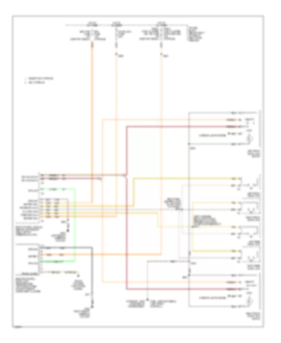
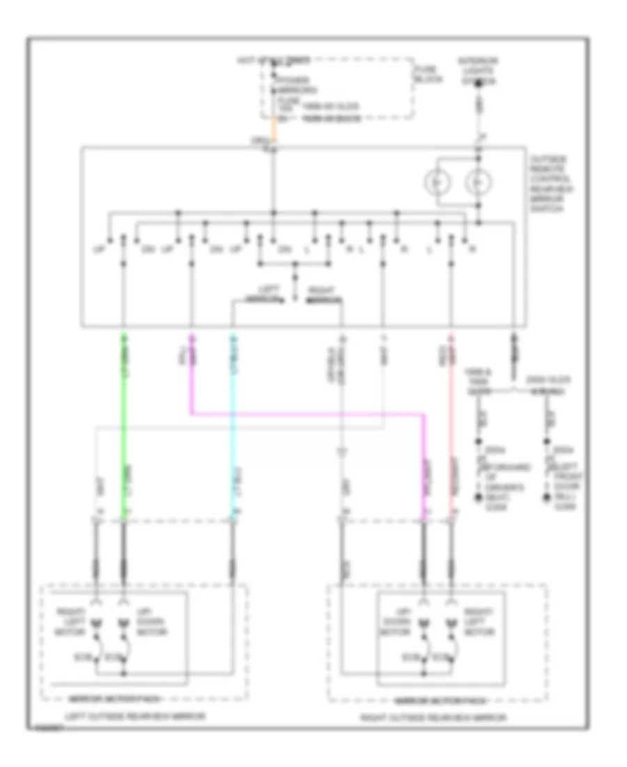
Power Mirrors Wiring Diagram for Oldsmobile Intrigue GL 2000
List of elements for Power Mirrors Wiring Diagram for Oldsmobile Intrigue GL 2000:
- & buick
- (left front door sill) g309
- 1998 & olds
- 1998-00 olds
- 1999-00 buick
- 2000 olds
- Driver's seat) g309
- Ecb
- Fuse block
- Hot at all times
- Interior lights system
- Left mirror
- Left outside rearview mirror
- Mirror motor pack
- Nca
- Outside remote control rearview mirror switch
- Power mirrors fuse 10a 2a
- Right mirror
- Right outside rearview mirror
- Right/ left motor
- S504
- Up/ down motor
POWER SEATS
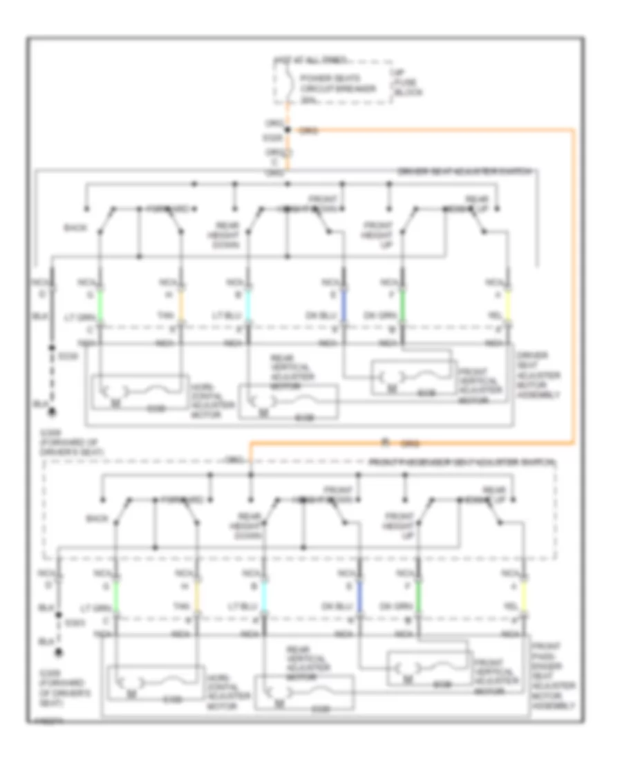
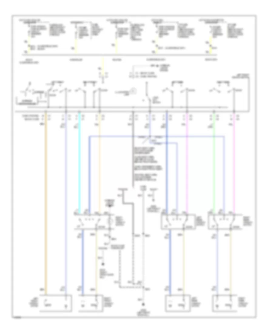
6-Way Power Seat Wiring Diagram for Oldsmobile Intrigue GL 2000
List of elements for 6-Way Power Seat Wiring Diagram for Oldsmobile Intrigue GL 2000:
- Back
- Driver seat adjuster motor assembly
- Driver seat adjuster switch
- Ecb
- Forward
- Front height down
- Front height up
- Front pass- enger seat adjuster motor assembly
- Front passenger seat adjuster switch
- Front vertical adjuster motor
- G309 (forward of driver's seat)
- Hori- zontal adjuster motor
- Hot at all times
- I/p fuse block
- Nca
- Power seats circuit breaker 30a
- Rear height down
- Rear height up
- Rear vertical adjuster motor
- S303
- S326
- S330
- Tan
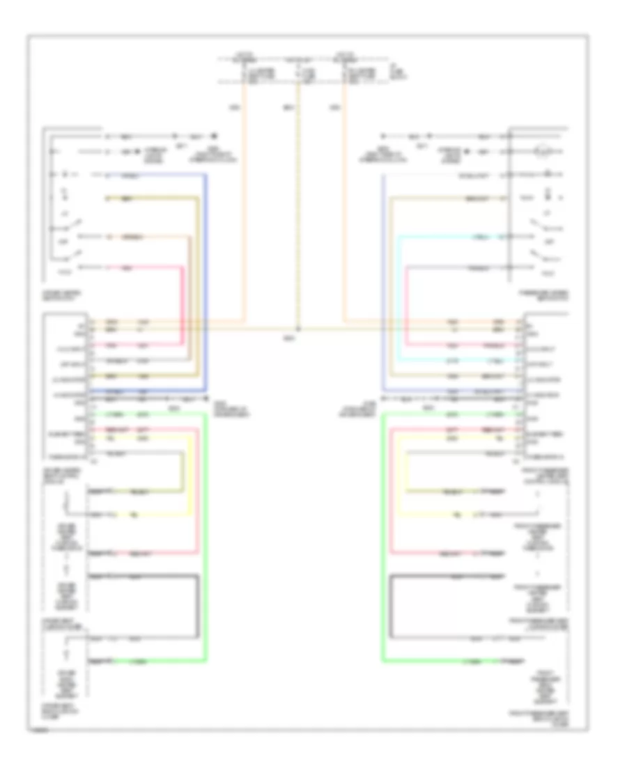
Heated Seats Wiring Diagram for Oldsmobile Intrigue GL 2000
List of elements for Heated Seats Wiring Diagram for Oldsmobile Intrigue GL 2000:
- Driver back heated seat element
- Driver heated seat control module
- Driver heated seat cushion element
- Driver heated seat cushion thermistor
- Driver heated seat switch
- Driver seat back cushion cover
- Driver seat cushion cover
- Element feed
- Front passenger back heated seat element
- Front passenger heated seat control module
- Front passenger heated seat cushion element
- Front passenger heated seat cushion thermistor
- Front passenger seat back cushion cover
- Front passenger seat cushion cover
- G309 (forward of driver's seat)
- Gnd
- Hi indicator
- Hi/lo
- Hi/lo input
- Hot at all times
- Hot in on
- Hvac fuse 10a
- I/p fuse block
- Ign3
- Interior lights system
- Lh heated seat fuse 15a
- Lo indicator
- Nca
- Off
- Off input
- Passenger heated seat switch
- Pnk
- Rh heated seat fuse 15a
- S205 (right side of steering column)
- S211
- S323
- S330
- S333
- Thermistor in
POWER TOP/SUNROOF
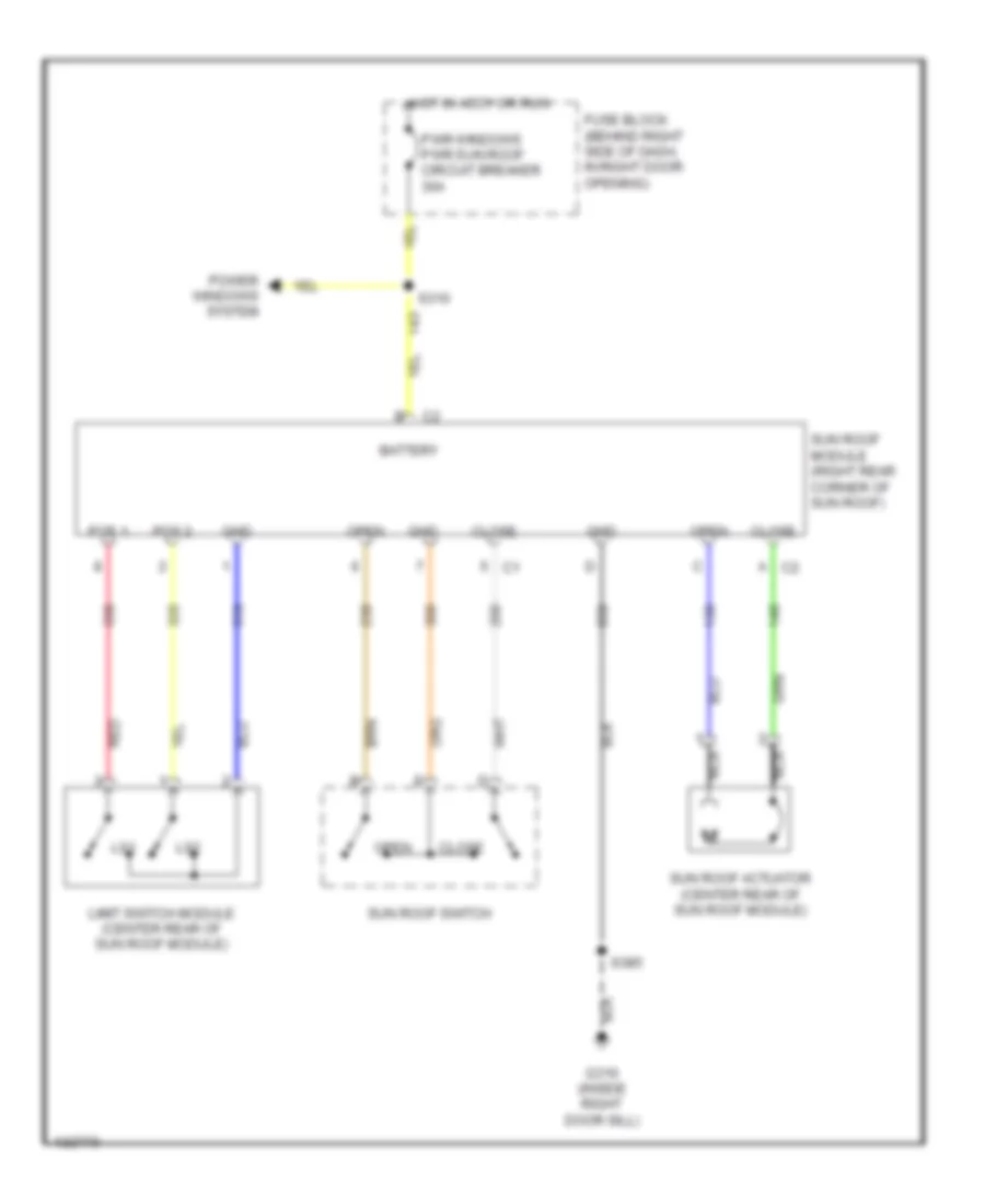
Power Top/Sunroof Wiring Diagrams for Oldsmobile Intrigue GL 2000
List of elements for Power Top/Sunroof Wiring Diagrams for Oldsmobile Intrigue GL 2000:
- Battery
- Close
- Fuse block (behind right side of dash, in right door opening)
- G316 (inside right door sill)
- Gnd
- Hot in accy or run
- Limit switch module (center rear of sun roof module)
- Ls1
- Ls2
- Nca
- Open
- Pos 1
- Pos 2
- Power windows system
- Pwr windows pwr sun roof circuit breaker 30a
- Red
- S310
- S385
- Sun roof actuator (center rear of sun roof module)
- Sun roof module (right rear corner of sun roof)
- Sun roof switch
POWER WINDOWS
Power Window Wiring Diagram for Oldsmobile Intrigue GL 2000
List of elements for Power Window Wiring Diagram for Oldsmobile Intrigue GL 2000:
- (buick)
- (buick, olds)
- (buick: body harn, on floor under driver's seat)
- (chev, pontiac)
- (chev: crossbody harn below right front seat)
- (olds: body harn, center of floor behind front seats)
- (oldsmobile: 2000)
- (oldsmobile: 2001)
- (pontiac: body harn, on floor near center of vehicle)
- Buick
- Buick oldsmobile: 2000
- Buick, olds chevrolet
- Buick: 2001
- Chev, olds
- Chevrolet
- Down
- Ecb
- Express
- Express down module
- Fuse block (behind right side of dash, in glove box opening)
- Fuse block (behind right side of dash, in right door opening)
- Fuse block (on right side of dash)
- G309 (left front door sill)
- G316 (right front door sill)
- Hot in acc, or run
- Hot in acc, run or during rap
- Hot in run
- Hot in run & start or during rap
- I/p fuse block (behind right side of dash, in right door opening)
- Illumination lamp
- Interior lights system
- Left front
- Left front window motor
- Left front window switch
- Left rear
- Left rear window motor
- Left rear window switch
- Lock out switch
- Oldsmobile: 2001
- Pontiac
- Power window circuit breaker 20a
- Pwr wdo circuit breaker 25a
- Pwr window pwr sunroof circuit breaker 30a
- Pwr windows pwr sunroof circuit breaker 30a
- Right front
- Right front window motor
- Right front window switch
- Right rear
- Right rear window motor
- Right rear window switch
- S303
- S307
- S310
- S310 s410
- S410
- S504
- S505
- S604
- Tan
RADIO
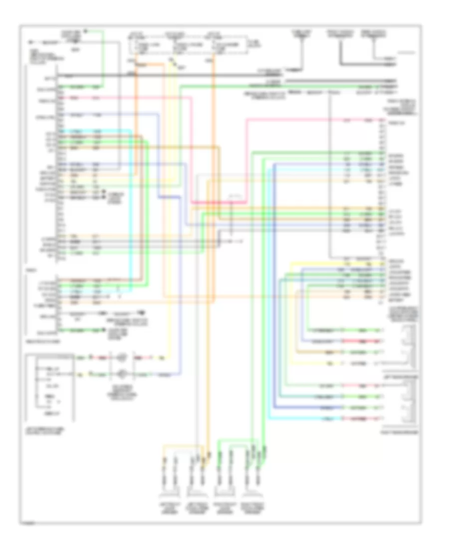
Radio Wiring Diagrams, with Amplifier for Oldsmobile Intrigue GL 2000
List of elements for Radio Wiring Diagrams, with Amplifier for Oldsmobile Intrigue GL 2000:
- (behind dash, right of steering column)
- A10
- A11
- A12
- Ant in
- B10
- B11
- B12
- Bare
- Battery
- Cd changer fuse 10a
- Cd com
- Cd in
- Computer data lines system
- Drain
- E & c data
- E10
- E11
- E12
- E13
- E14
- E15
- E16
- F10
- F11
- F12
- F13
- F14
- F15
- F16
- Fixed mast antenna
- Front window antenna grid
- Fuse block
- Fused feed
- G202
- G202 (behind dash, right of steering column)
- Ground
- Hot at all times
- Hot in acc or run
- Inflatable restraint steering wheel module coil
- Interior lights system
- Left front door speaker
- Left front door upper speaker
- Left rear speaker
- Left steering wheel control switches
- Lf feed
- Lf low
- Lf rtn
- Lf spkr
- Low frequency audio amplifier (center of rear window panel)
- Low rtn
- Lr +
- Lr low
- Lr rtn
- Lr spk feed
- Lr sub feed
- Lr sub rtn
- Lt cd sig
- Nca
- Pnk
- Prog
- Radio
- Radio antenna module (on rear window header panel)
- Radio on
- Radio pwr
- Radio, cruise fuse 2a
- Radio, hvac fuse 15a
- Rap pwr
- Rear window antenna grid
- Red
- Remote cd player
- Rf +
- Rf low
- Rf spkr
- Right front door speaker
- Right front door upper speaker
- Right rear speaker
- Rr +
- Rr feed
- Rr low
- Rr return
- Rr spkr
- Rr sub feed
- Rt cd sig
- S202
- S227
- S239
- S418
- Seek up
- Shield
- Strg ctrl
- Tan
- Vf dim
- Vol dn
- Vol up
- W/ fixed mast antenna
- W/ rear window antenna
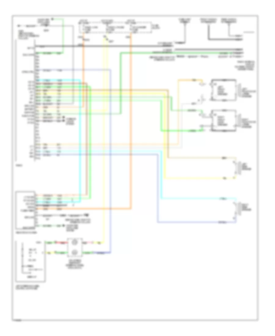
Radio Wiring Diagrams, without Amplifier for Oldsmobile Intrigue GL 2000
List of elements for Radio Wiring Diagrams, without Amplifier for Oldsmobile Intrigue GL 2000:
- (behind dash, right of steering column)
- A c1
- A c2
- Ant in
- B c2
- Bare
- Battery
- C1 a
- C1 b
- C2 a
- C2 b
- Cd changer fuse 10a
- Cd com
- Cd in
- Computer data lines system
- Drain
- E & c data
- E10
- E11
- E12
- E13
- E14
- E15
- E16
- F10
- F11
- F12
- F13
- F14
- F15
- F16
- Fixed mast antenna
- Front window antenna grid
- Fuse block
- Fused feed
- G202
- G202 (behind dash, right of steering column)
- Ground
- Hot at all times
- Hot in acc or run
- Inflatable restraint steering wheel module coil
- Interior lights system
- Left front door speaker
- Left front door upper speaker
- Left rear speaker
- Left steering wheel control switches
- Lf +
- Lf -
- Lr +
- Lr -
- Lt cd sig
- Nca
- Prog
- Radio
- Radio antenna module (on rear window header panel)
- Radio pwr
- Radio, cruise fuse 2a
- Radio, hvac fuse 15a
- Rap pwr
- Rear window antenna grid
- Red
- Remote cd player
- Rf -
- Right front door speaker
- Right front door upper speaker
- Right rear speaker
- Rr +
- Rr -
- Rr+
- Rt cd sig
- S202
- S227
- S239
- S418
- Seek up
- Strg ctrl
- Tan
- Vf dim
- Vol dn
- Vol up
- W/ fixed mast antenna
- W/ rear window antenna
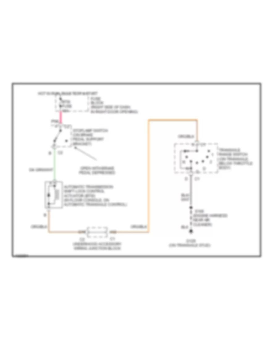
SHIFT INTERLOCKS
Shift Interlock Wiring Diagram for Oldsmobile Intrigue GL 2000
List of elements for Shift Interlock Wiring Diagram for Oldsmobile Intrigue GL 2000:
- (engine harness near air cleaner)
- (on transaxle stud)
- A12
- Automatic transmission shift lock control actuator (btsi) (in floor console, on automatic transaxle control)
- Btsi fuse 10a
- C11
- Fuse block (right side of dash, in right door opening)
- G129
- Hot in run, bulb test & start
- Open with brake pedal depressed
- Pnk
- S106
- Stoplamp switch (on brake pedal support bracket)
- Transaxle range switch (on transaxle, below throttle body)
- Underhood accessory wiring junction block
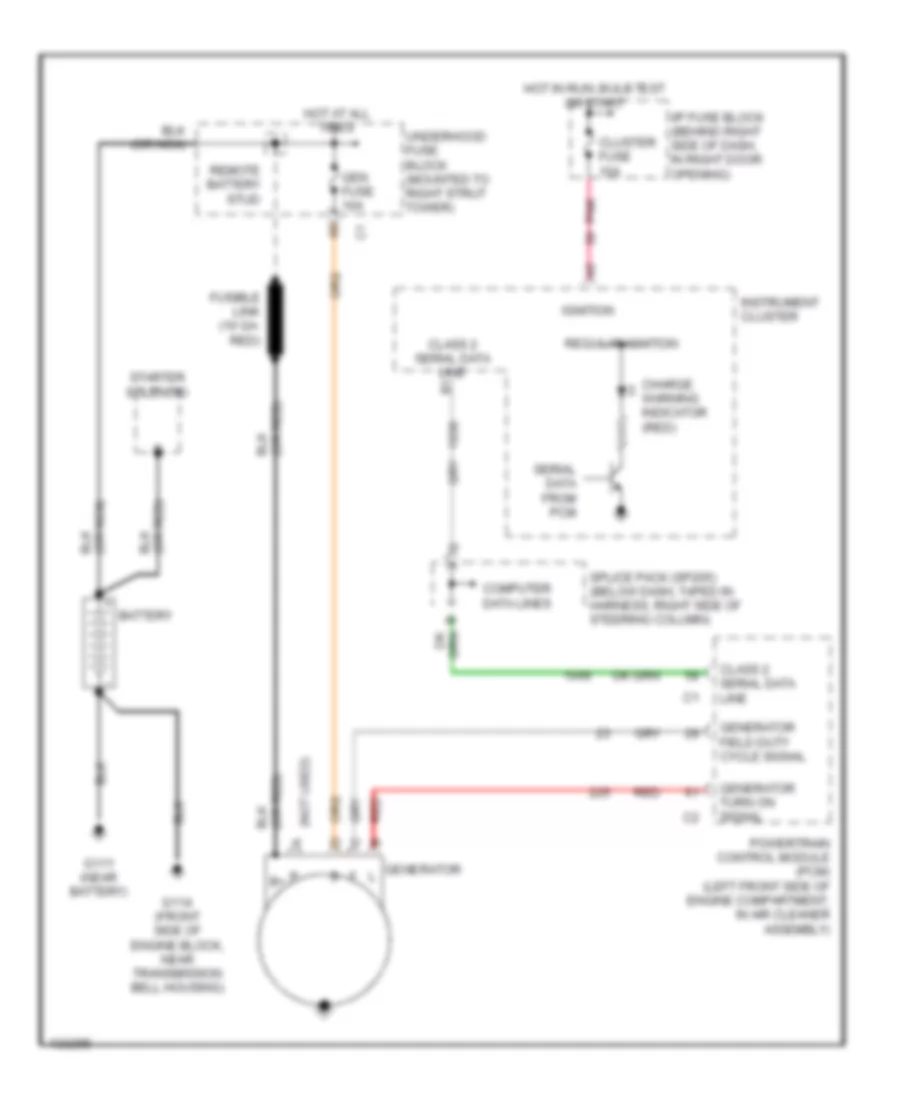
STARTING/CHARGING
Charging Wiring Diagram for Oldsmobile Intrigue GL 2000
List of elements for Charging Wiring Diagram for Oldsmobile Intrigue GL 2000:
- (not used)
- Battery
- Charge warning indicator (red)
- Class 2 serial data line
- Cluster fuse 10a
- Computer data lines
- Fusible link (10 ga- red)
- G111 (near battery)
- G114 (front side of engine block, near transmission bell housing)
- Gen fuse 10a
- Generator field duty cycle signal
- Generator l
- Generator turn on signal
- Hot at all times
- Hot in run, bulb test or start
- I/p fuse block (behind right side of dash, in right door opening)
- Ignition
- Instrument cluster
- P b+
- Pnk
- Powertrain control module (pcm) (left front side of engine compartment, in air cleaner assembly)
- Red
- Regular ignition
- Remote battery stud
- Serial data from pcm
- Splice pack (sp205) (below dash, taped in harness, right side of steering column)
- Starter solenoid
- Underhood fuse block (mounted to right strut tower)
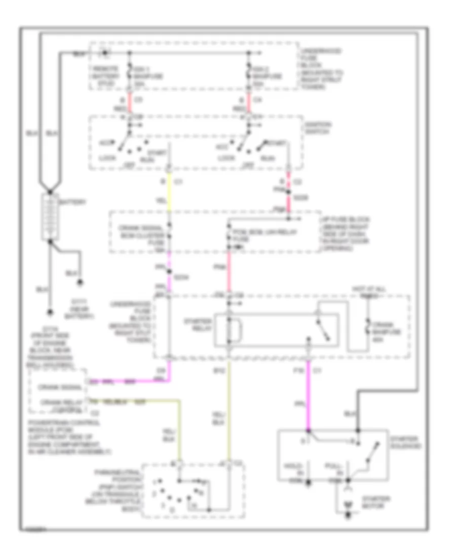
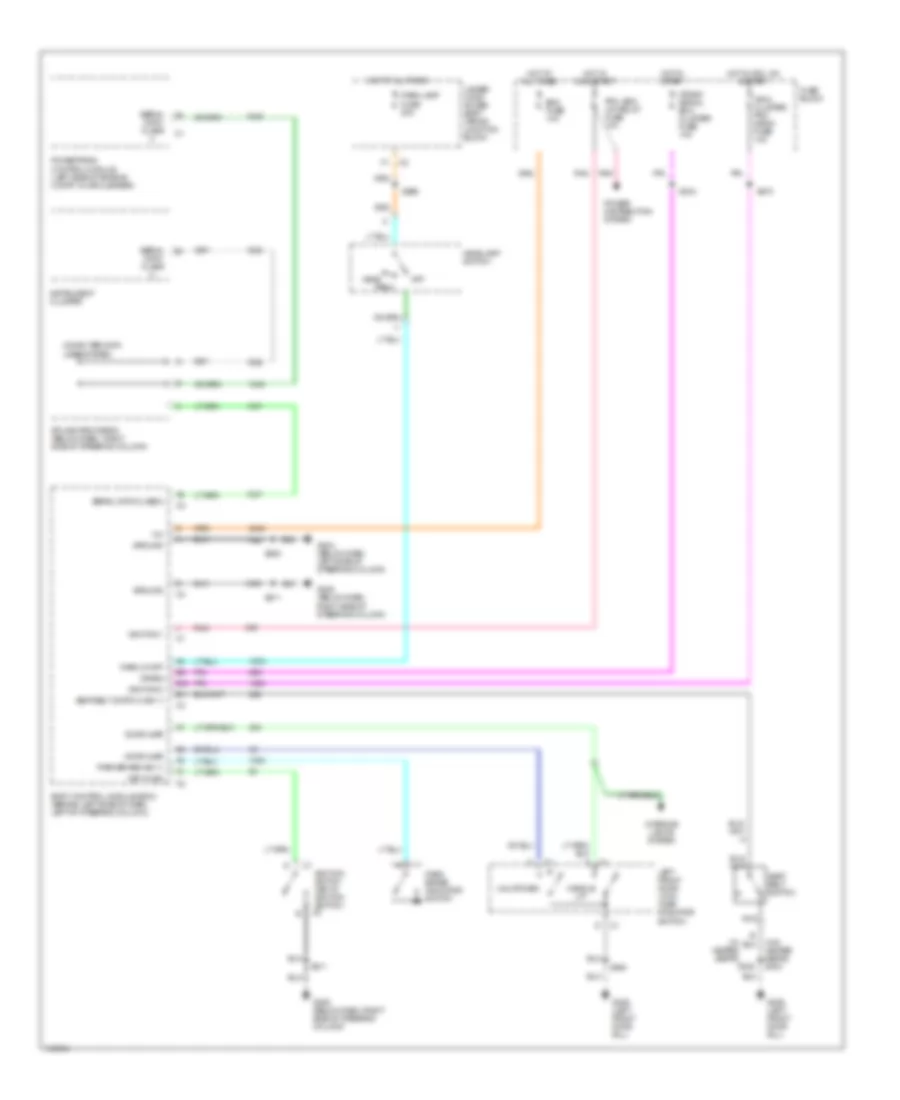
Starting Wiring Diagram for Oldsmobile Intrigue GL 2000
List of elements for Starting Wiring Diagram for Oldsmobile Intrigue GL 2000:
- Acc
- B12
- Battery
- Crank maxifuse 40a
- Crank relay control
- Crank signal
- Crank signal, bcm cluster fuse 10a
- F10
- G111 (near battery)
- G114 (front side of engine block, near transmission bell housing)
- Hold- in coil
- Hot at all times
- I/p fuse block (behind right side of dash, in right door opening)
- Ign 1 maxifuse 30a
- Ign 2 maxifuse 50a
- Ignition switch
- Lock
- Off
- Park/neutral position (pnp) switch (on transaxle, below throttle body)
- Pcm, bcm, u/h relay fuse 10a
- Pnk
- Powertrain control module (pcm) (left front side of engine compartment, in air cleaner assembly)
- Pull- in coil
- Red
- Remote battery stud
- Run
- S228
- S234
- Start
- Starter motor
- Starter relay
- Starter solenoid
- Underhood fuse block (mounted to right strut tower)
- Underhood fuse block (mounted to right stut tower)
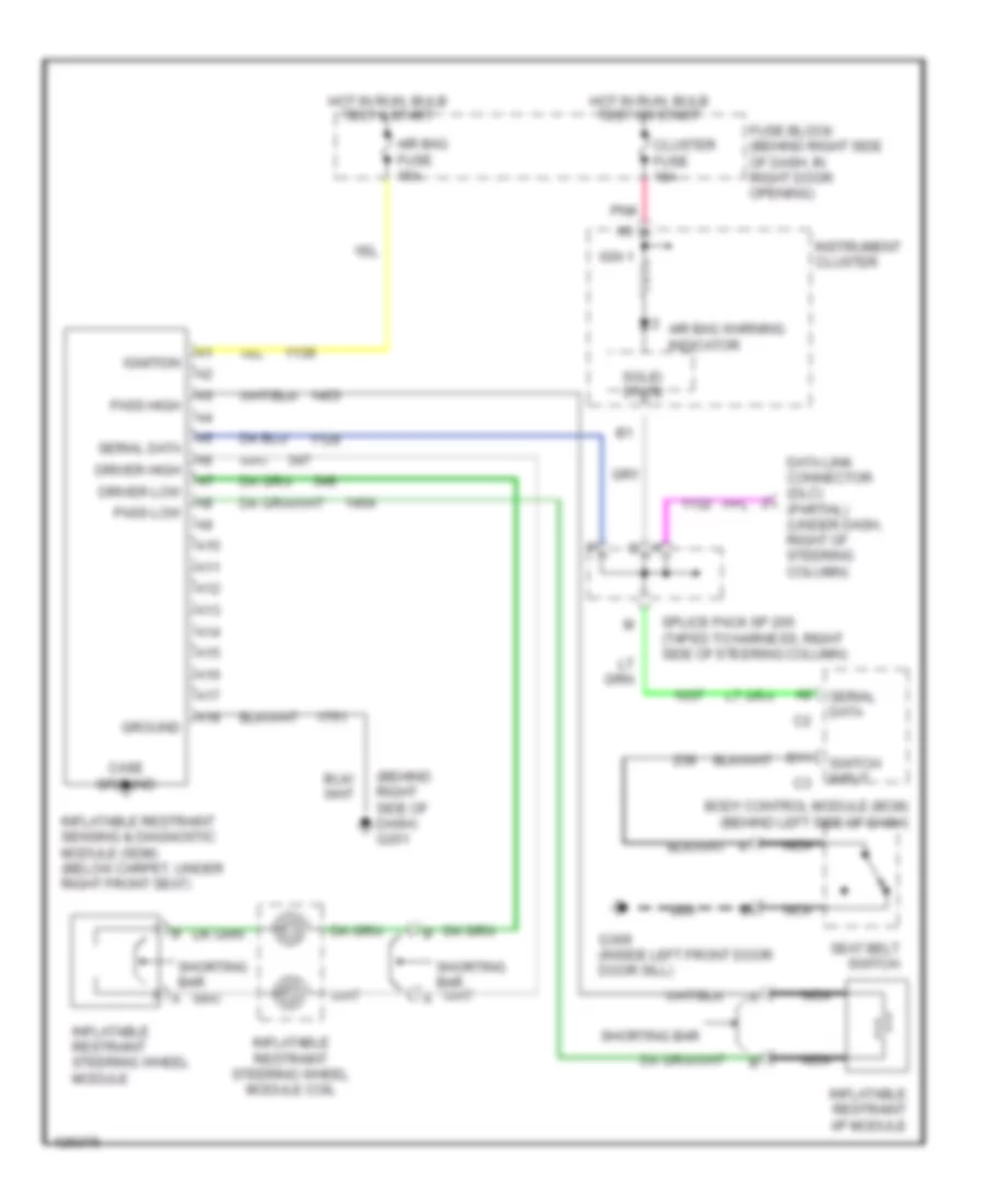
SUPPLEMENTAL RESTRAINTS
Supplemental Restraint Wiring Diagram for Oldsmobile Intrigue GL 2000
List of elements for Supplemental Restraint Wiring Diagram for Oldsmobile Intrigue GL 2000:
- (behind right side of dash) g201
- A10
- A11
- A12
- A13
- A14
- A15
- A16
- A17
- A18
- Air bag fuse 15a
- Air bag warning indicator
- B11
- Body control module (bcm) (behind left side of dash)
- Case ground
- Cluster fuse 10a
- Data link connector (dlc) (partial) (under dash, right of steering column)
- Driver high
- Driver low
- Fuse block (behind right side of dash, in right door opening)
- G309 (inside left front door door sill)
- Ground
- Hot in run, bulb test & start
- Hot in run, bulb test or start
- Ign 1
- Ignition
- Inflatable restraint i/p module
- Inflatable restraint sensing & diagnostic module (sdm) (below carpet, under right front seat)
- Inflatable restraint steering wheel module
- Inflatable restraint steering wheel module coil
- Instrument cluster
- Nca
- Pass high
- Pass low
- Pnk
- Seat belt switch
- Serial data
- Shorting bar
- Solid state
- Splice pack sp 205 (taped to harness, right side of steering column)
- Switch input
TRANSMISSION
3.5L
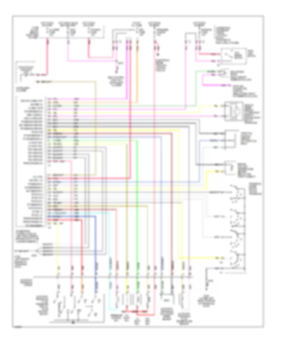
3.5L VIN H, A/T Wiring Diagram, 4T65-E for Oldsmobile Intrigue GL 2000
List of elements for 3.5L VIN H, A/T Wiring Diagram, 4T65-E for Oldsmobile Intrigue GL 2000:
- 1-2 shift sol
- 2-3 shift sol
- 5v reference a
- A/t iss sensor hi
- A/t iss sensor lo
- Atf sensor return
- Automatic transaxle (4t65-e)
- Automatic transaxle fluid pressure manual valve position switch
- Automatic transaxle fluid temperature sensor
- Automatic transaxle input shaft speed sensor
- Battery in
- Body control module & instrument cluster
- Class ii data
- Cluster fuse 10a
- Data link connector (partial) (below dash, right of steering column)
- Ecm fuse 10a
- Ect sensor in
- Ect sensor return
- Electronic brake traction control module
- Eng emis fuse 10a
- Engine coolant temperature sensor (below the throttle body)
- Fuse block (behind right side of dash)
- G129 (left side of engine on transaxle stud)
- G129 (lower left side of engine, on transaxle stud)
- Hot at all times
- Hot in run or start
- Hot in run, bulb test or start
- Ign 0 fuse 10a
- Ignition 1 in
- Ignition wake up in
- Instrument cluster
- Malfunction indicator lamp
- Mil ctrl
- Pc sol hi
- Pc sol lo
- Pcm ground
- Pcm-bcm fuse 10a
- Pnk
- Powertrain control module (left front side of engine compt, in air cleaner assembly)
- Pressure control sol
- Red
- Rev
- S106
- S270
- Splice pack sp205 (right side of steering column)
- Stop lamp switch
- Tan
- Tcc pwm sol
- Tcc release
- Tcc release in
- Tcc/ brake switch
- Tcc/brake sw in
- Tft sensor in
- Throttle position sensor (on throttle body)
- Tp sensor in
- Tp sensor return
- Tr sw in-a
- Tr sw in-b
- Tr sw in-c
- Tr sw in-p
- Trans range a in
- Trans range b in
- Trans range c in
- Trans/abs fuse 26 10a
- Transaxle range switch (top of transaxle)
- Underhood accessory wiring junction block (mounted to right strut tower)
- Vehicle speed sensor (lower right rear of engine compt, end of transaxle)
- Vss hi (signal)
- Vss lo (ground)
TRUNK, TAILGATE, FUEL DOOR
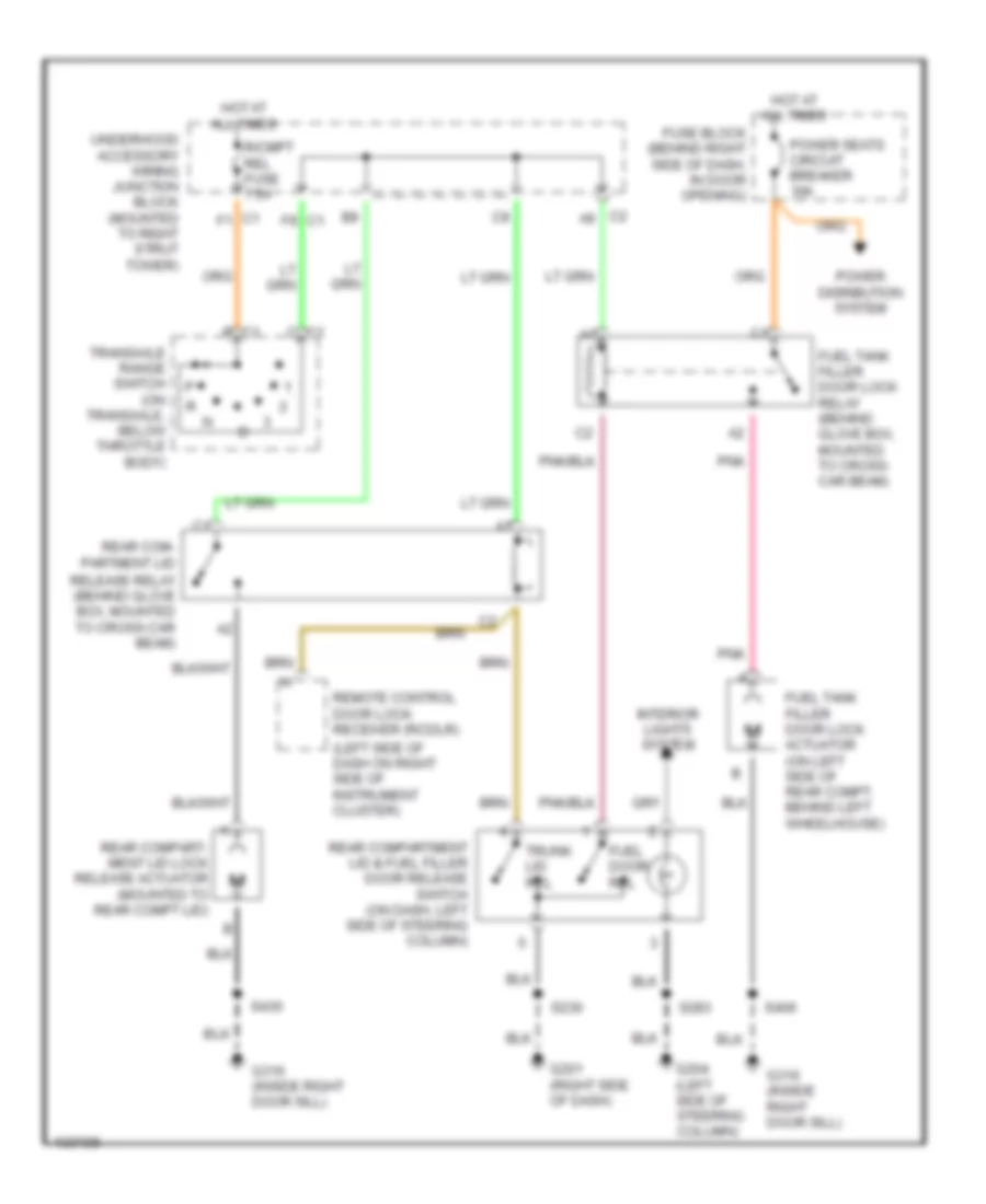
Trunk, Tailgate, Fuel Door Wiring Diagrams for Oldsmobile Intrigue GL 2000
List of elements for Trunk, Tailgate, Fuel Door Wiring Diagrams for Oldsmobile Intrigue GL 2000:
- (left side of dash on right side of instrument cluster)
- B c1
- C1 c
- C1 f1
- C2 a9
- F9 c1
- Fuel door rel
- Fuel tank filler door lock actuator (on left side of rear compt, behind left wheelhouse)
- Fuel tank filler door lock relay (behind glove box, mounted to cross- car beam)
- Fuse block (behind right side of dash, in door opening)
- G201 (right side of dash)
- G204 (left side of steering column)
- G316 (inside right door sill)
- G316 (inside right door sill)
- Hot at all times
- Interior lights system
- Pnk
- Power disribution system
- Power seats circuit breaker 30a
- R/cmpt rel fuse 7.5a
- Rear com- partment lid
- Rear compart- ment lid lock release actuator (mounted to rear compt lid)
- Rear compartment lid & fuel filler door release switch (on dash, left side of steering column)
- Release relay (behind glove box, mounted to cross-car beam)
- Remote control door lock receiver (rcdlr)
- S230
- S283
- S406
- S430
- Transaxle range switch (on transaxle, below throttle body)
- Trunk lid rel
- Underhood accessory wiring junction block (mounted to right strut tower)
WARNING SYSTEMS
Warning System Wiring Diagrams for Oldsmobile Intrigue GL 2000
List of elements for Warning System Wiring Diagrams for Oldsmobile Intrigue GL 2000:
- (w/ heated seats)
- (w/o heated seats) s303
- 12v
- B10
- B11
- Bcm fuse 10a
- Body control module (bcm) (behind left side of dash, left of steering column)
- Computer data lines system
- Crank
- Crank signal, bcm cluster fuse 10a
- Door ajar
- Fuse block
- G204 (below dash, left side of steering column)
- G205 (below dash, right side of steering column)
- G309 (left front door sill)
- Ground
- Handle
- Head
- Headlamp switch
- Hot at all times
- Hot in acc, on & start
- Hot in on & start
- Hot in start
- Ign 0, cluster, pcm & bcm fuse 10a
- Ignition 0
- Ignition 1
- Ignition switch (key in ignition switch) c2
- Instrument cluster
- Interior lights system
- Key in ign
- Left front door lock (ajar indicator switch)
- Nca
- Off
- Park
- Park brake (ign 1)
- Park brake indicator switch
- Park lamp fuse 20a
- Park lp off
- Pcm, bcm u/h relay fuse 10a
- Pnk
- Power distribution system
- Powertrain control module (left side of engine compt, in air cleaner)
- S211
- S234
- S270
- S283
- S296
- S330
- S504
- Seat belt switch
- Seat belt switch (ign 1)
- Serial data class
- Serial data class 2
- Splice pack sp205 (below dash, right side of steering column)
- Under- hood acces- sory wiring junction block
- Unlatched
WIPER/WASHER
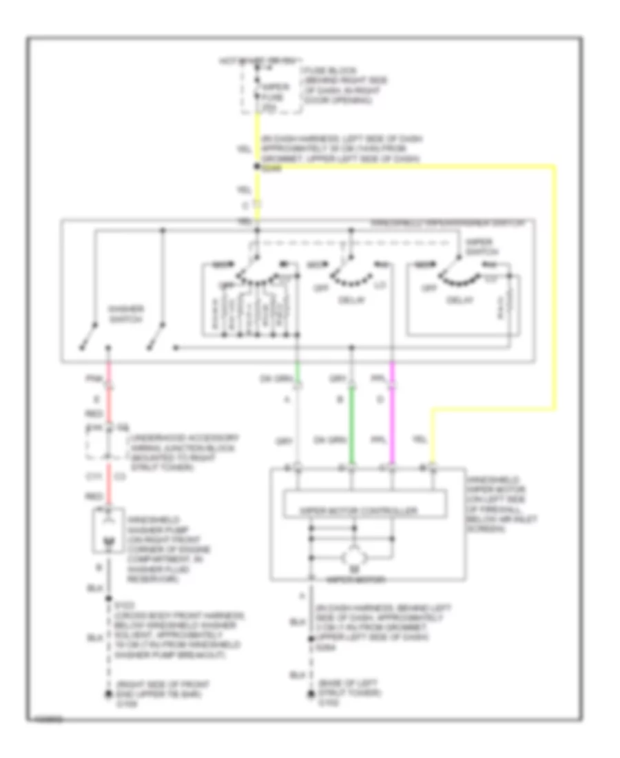
Wiper/Washer Wiring Diagram for Oldsmobile Intrigue GL 2000
List of elements for Wiper/Washer Wiring Diagram for Oldsmobile Intrigue GL 2000:
- (base of left strut tower) g102
- (right side of front end upper tie bar) g109
- 3 cm (1 in) from grommet, upper left side of dash) s284
- C11
- Delay
- E11
- Fuse block (behind right side of dash, in right door opening)
- Grommet, upper left side of dash) s249
- Hot in acc or on
- Mist
- Off
- Pnk
- Red
- S123 (cross body front harness, below windshield washer solvent, approximately 19 cm (7 in) from windshield washer pump breakout)
- Underhood accessory wiring junction block (mounted to right strut tower)
- Washer switch
- Windshield washer pump (on right front corner of engine compartment, in washer fluid reservoir)
- Windshield wiper motor (on left side of firewall, below air inlet screen)
- Windshield wiper/washer switch
- Wiper fuse 25a
- Wiper motor
- Wiper motor controller
- Wiper switch