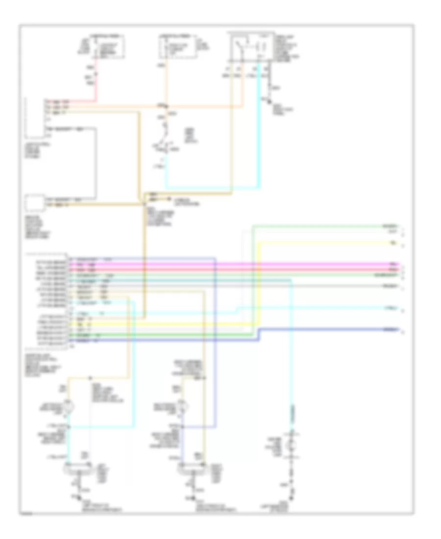
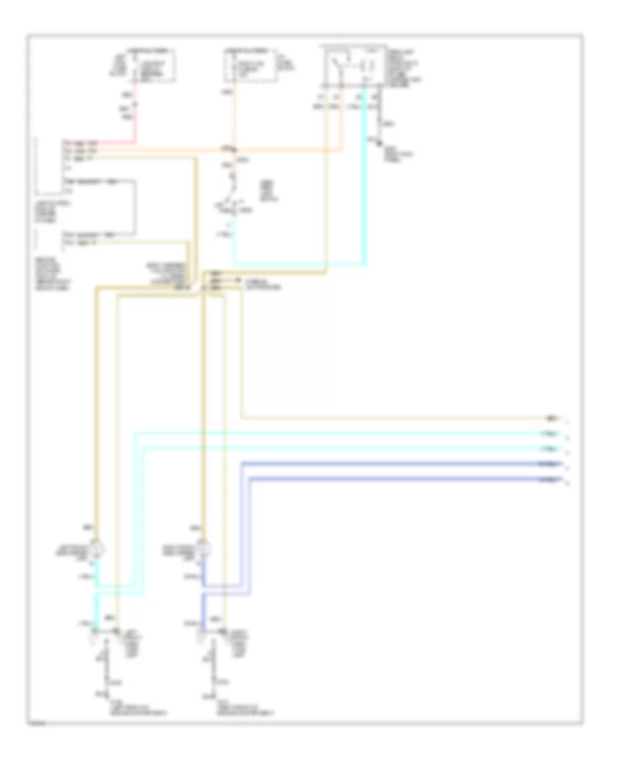
AIR CONDITIONING
Air Conditioning Wiring Diagrams (1 of 2) for Oldsmobile LSS 1997

List of elements for Air Conditioning Wiring Diagrams (1 of 2) for Oldsmobile LSS 1997:
- (body harness, 8 cm from right i/p cross-channel)
- (body harness, at right wheelhouse)
- (body harness, near a/c accumulator)
- (engine harness, 6 cm from a/c compressor clutch breakout)
- (i/p harness, below right side of i/p)
- (right front of engine compartment)
- (top left side of i/p)
- (top right side of i/p)
- +5v
- A/c compres- sor clutch
- A/c compres- sor clutch diode
- A/c compressor control relay (center rear of engine compartment)
- A/c request
- Ambient temperature sensor (center front of vehicle)
- Battery
- Blower control
- Blower control module (center rear of engine compartment)
- Blower feedback
- Blower motor
- Clock driver
- Computer data lines system
- Data line
- Data link
- Data link connector (below left side of i/p)
- E10
- E11
- E12
- E13
- E14
- E15
- E16
- F10
- F11
- F12
- F13
- F14
- F15
- F16
- Fuse 10a
- Fuse 30a
- Fuse 5a 15a
- Fuse 6e 10a
- Fuse 9c 10a
- G101
- G101 (right front of engine compartment)
- G203 (right kickpad)
- Ground
- Hot at all times
- Hot in run
- Hot in run, or start
- Hvac programmer (behind right side of i/p)
- I/p fuse block
- Ignition
- In-vehicle temperature sensor (behind center of i/p)
- Left solar sensor
- Motor control
- Motor pos feedbk
- Nca
- Pass control
- Passenger air mix valve actuator
- Pnk
- Red
- Right i/p power distribution center
- Right solar sensor
- Right underhood fuse block
- S102
- S107
- S108
- S207 (body harness, 12 cm from center i/p cross-channel)
- S241 (body harness, 40 cm from lamp control module)
- S268 (body harness, 23.6 cm from hvac programmer connector)
- S270
- S279 (body harn, 2 cm from end of right i/p cross- channel)
- S308 (body harn, 58 cm from g203)
- S915
- Sensor input
- Sensor return
- Signal driver
- Tan
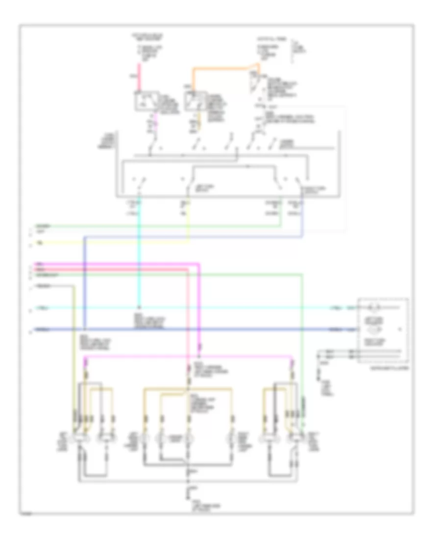
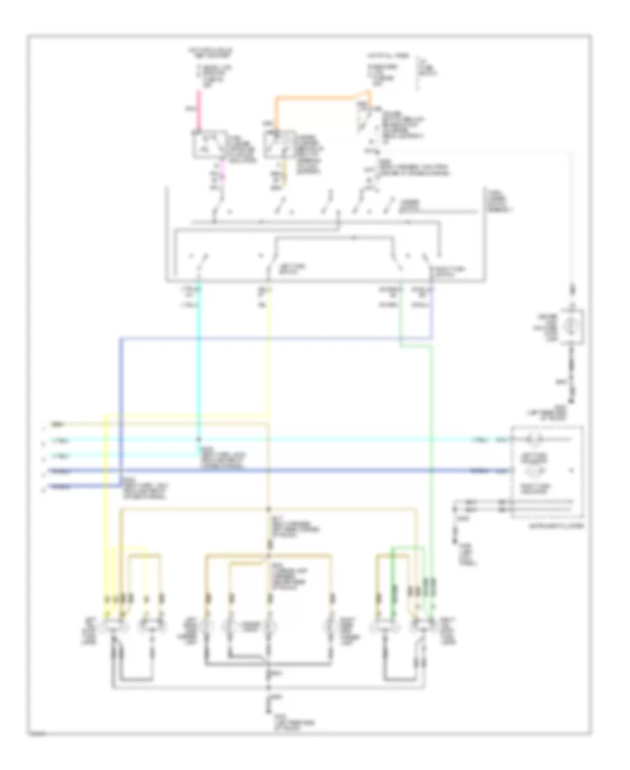
Air Conditioning Wiring Diagrams (2 of 2) for Oldsmobile LSS 1997
List of elements for Air Conditioning Wiring Diagrams (2 of 2) for Oldsmobile LSS 1997:
- (body harness, 27 cm from left maxi fuse block)
- (body harness, near g203)
- (i/p harness, 12.5 cm from radio)
- (left front side of engine compartment)
- A a
- A/c refrigerant pressure sensor (lower right front of engine)
- A/c request
- A1 a1
- A2 a2
- A3 a3
- A4 a4
- A5 a5
- A6 a6
- A7 a7
- A8 a8
- B b
- B1 b1
- B2 b2
- B3 b3
- B4 b4
- B5 b5
- B6 b6
- B7 b7
- B8 b8
- C c
- Clock driver
- Compressor control
- D d
- Date led out
- Driver information center
- Econ led out
- Engine coolant temperature sensor (left rear of engine)
- F13
- Fan relay ctrl
- Fuel led out fuel led out
- Fuse 40a
- Fuse 5c 10a
- G100
- G200 (left kick pad)
- G203 (right kickpad)
- Gauge led out
- Ground
- High speed coolant fan relay (left rear of engine compartment)
- Hot in run
- Hvac hvac control assembly control assembly
- I/p fuse block
- Ignition
- Illumination
- Interior lights system
- Left coolant fan motor
- Left maxi fuse block
- Low speed coolant fan relay (left rear of engine compartment)
- Oil led out
- Passenger climate control assembly
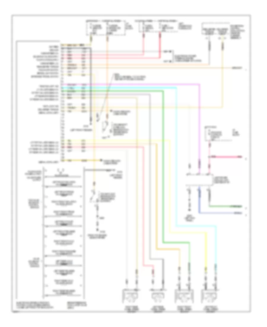
- Powertrain control module (behind right side of i/p)
- Pressure sw input
- Red
- Right coolant fan motor
- S104
- S121 (engine harness, near accumulator)
- S124 (body harness, 10 cm from ebcm/ebtcm)
- S128 (body harn, 6.5cm from fan motor breakout)
- S213
- S308
- Sensor input
- Sensor return
- Signal driver
- Vsb a/c
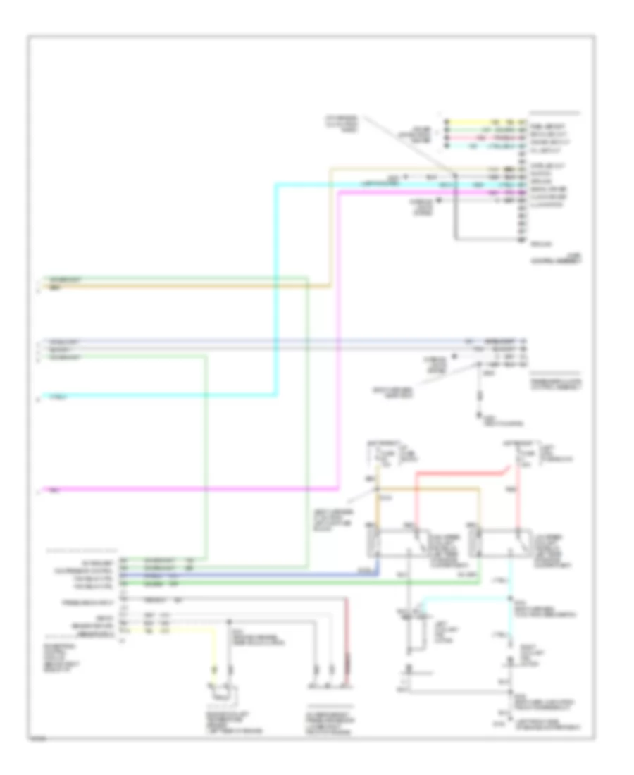
ANTI-LOCK BRAKES
Anti-lock Brake Wiring Diagrams (1 of 2) for Oldsmobile LSS 1997
List of elements for Anti-lock Brake Wiring Diagrams (1 of 2) for Oldsmobile LSS 1997:
- "anti-lock" ind
- "traction off" ind
- (front of engine, near starter)
- (left front fender)
- 800a
- 800b
- Brake light switch
- Brake pressure modulator valve (bpmv)
- Computer data lines system
- Cruise/shift interlock brake switch (brake pedal support)
- Delivered torque
- Delivered torque input
- Electronic brake & traction control module (ebcm/ebtcm) (lower left front of eng compt)
- Electronic power steering system (magna steer actuator)
- Extended travel switch
- Fuse 1 abs motor 40a
- Fuse 2 abs sol 40a
- Fuse b5 abs/ccr/ elc 10a
- Fuse b6 brake lps/ hazard 20a
- G100
- G125
- G200 (left kick panel)
- Ground
- Hot at all times
- Hot in run
- I/p fuse block
- Ign feed
- Ign/chime clstr/lcm fuse 1d 15a
- Lamp driver module (ldm) (center of i/p)
- Left front inlet valve solenoid
- Left front isolation valve solenoid
- Left front prime valve solenoid
- Left front release valve solenoid
- Left front wheel speed sensor
- Left rear hold valve solenoid
- Left rear release valve solenoid
- Left rear wheel speed sensor
- Left underhood fuse block
- Lf whl spd sens (hi)
- Lft frt whl spd sens (lo)
- Lft rear spd sens (hi)
- Lft rear whl spd sens (lo)
- Magnasteer (hi)
- Magnasteer (lo)
- Nca
- Pnk
- Powertrain control module (pcm) (near air cleaner assembly)
- Pump motor
- Pump motor power output
- Red
- Requested torque
- Requested torque output
- Right front hold valve solenoid
- Right front isolation valve solenoid
- Right front prime valve solenoid
- Right front release valve solenoid
- Right front wheel speed sensor
- Right rear hold valve solenoid
- Right rear release valve solenoid
- Right rear wheel speed sensor
- Rt frt whl spd sens (hi)
- Rt frt whl spd sens (lo)
- Rt rear whl spd sens (hi)
- Rt rear whl spd sens (lo)
- S208
- S225
- S228 (body harness, 17.5 cm from center i/p cross-channel)
- S262
- Serial data (uart)
- Tan
- Tcc/antilock brake switch (brake pedal support)
- Tcs on/off switch
- Tcs valve solenoid control signals
- Valve power output
- Valve solenoid control signals
Anti-lock Brake Wiring Diagrams (2 of 2) for Oldsmobile LSS 1997
List of elements for Anti-lock Brake Wiring Diagrams (2 of 2) for Oldsmobile LSS 1997:
- "antilock" indicator
- "traction active" indicator
- "traction off" indicator
- (buick)
- (buick-ub3)
- (front of right front fender)
- (olds)
- (pont)
- (pont-u2f or u50)
- (pont-ub3)
- (pontiac-u2f or u50)
- (pontiac-ub3)
- A15
- B13
- Bat
- Buick-u23
- Buick-ub3
- Buick-ub3 pont-ub3, u2f or u50
- F16
- From abs/tcs uart data line
- From pcm uart data line
- G c
- G101
- Hot in run, bulb test or start
- Instrument cluster
- Instrument cluster (pontiac) information center (buick)
- Olds
- Oldsmobile
- Pcm fuse 8 10a
- Pcm fuse 8 15a
- Pnk
- Pontiac
- Pontiac only
- Right i/p power distribution center
- S233
- S908
- S914 (i/p harn, 48 cm from radio connector)
- Solid state
- Traction control switch
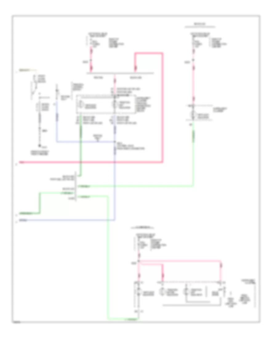
ANTI-THEFT
Forced Entry Wiring Diagram for Oldsmobile LSS 1997
List of elements for Forced Entry Wiring Diagram for Oldsmobile LSS 1997:
- (body harn, 14 cm from lamp control module conn breakout)
- (body harn, 20.5 cm from lamp control module conn breakout)
- (body harn, 31.5 cm from top edge of left kick panel)
- (body harn, 34 cm from ground bolted at center of right kick panel)
- (body harn, 42.5 cm from remote fucntion actuator module)
- (body harn, 9 cm from left edge of i/p cross-channel)
- (buic) (pont)
- (buick)
- (i/p harn, buick: 10 cm from breakout to 116-pin black conn below right side of i/p, near center; pontiac: 12 cm from i/p compt lamp breakout)
- 1995 vftc c
- Battery
- D b
- Data line
- Data link connector (behind i/p, right of steering column)
- Door lock input
- Door unlock input
- Door unlock input/output
- E10
- E11
- E12
- E13
- E16
- Exterior lamp input
- F10
- F13
- F16
- F4
- G200 (left kick panel)
- G200 (left kickpad)
- Ground
- Headlamps alarm output
- Horn relay control
- Horns system (horn relay)
- Hot at all times
- Indicator control
- Junction connector c340 (left front door sill, taped to harness)
- Key unlock input
- Lamp control module (center of i/p)
- Left front door lock lock
- Left front door latch switch
- Left front door lock cylinder switch
- Left front door open in
- Left rear door latch switch
- Multi-function alarm, lock and lighting module (behind right side of i/p)
- Passenger door jamb
- Passkey circuit
- Relay center (right kick panel)
- Remote function actuator module (behind right
- Right front door lock lock
- Right front door latch switch
- Right front door lock cylinder switch
- Right rear door latch assembly
- S210
- S218
- S225
- S248
- S251
- S252
- S278
- S289
- S291
- S310
- S603
- Side of i/p)
- Switch
- Tamper switch (buick)
- Tamper switch input
- Trunk lid tamper switch (near latch)
- Trunk/rel/pwr ant/rac lks fuse 2 15a
- Unlock
- Unlock switch
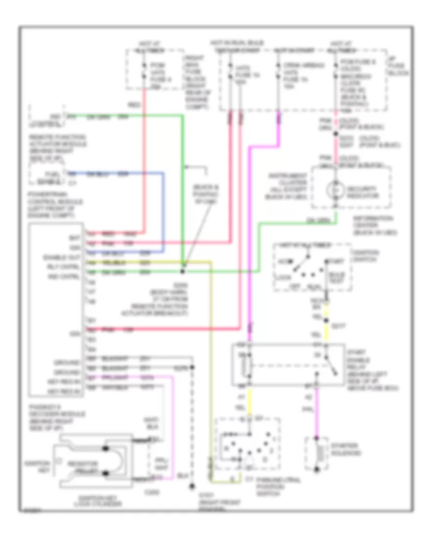
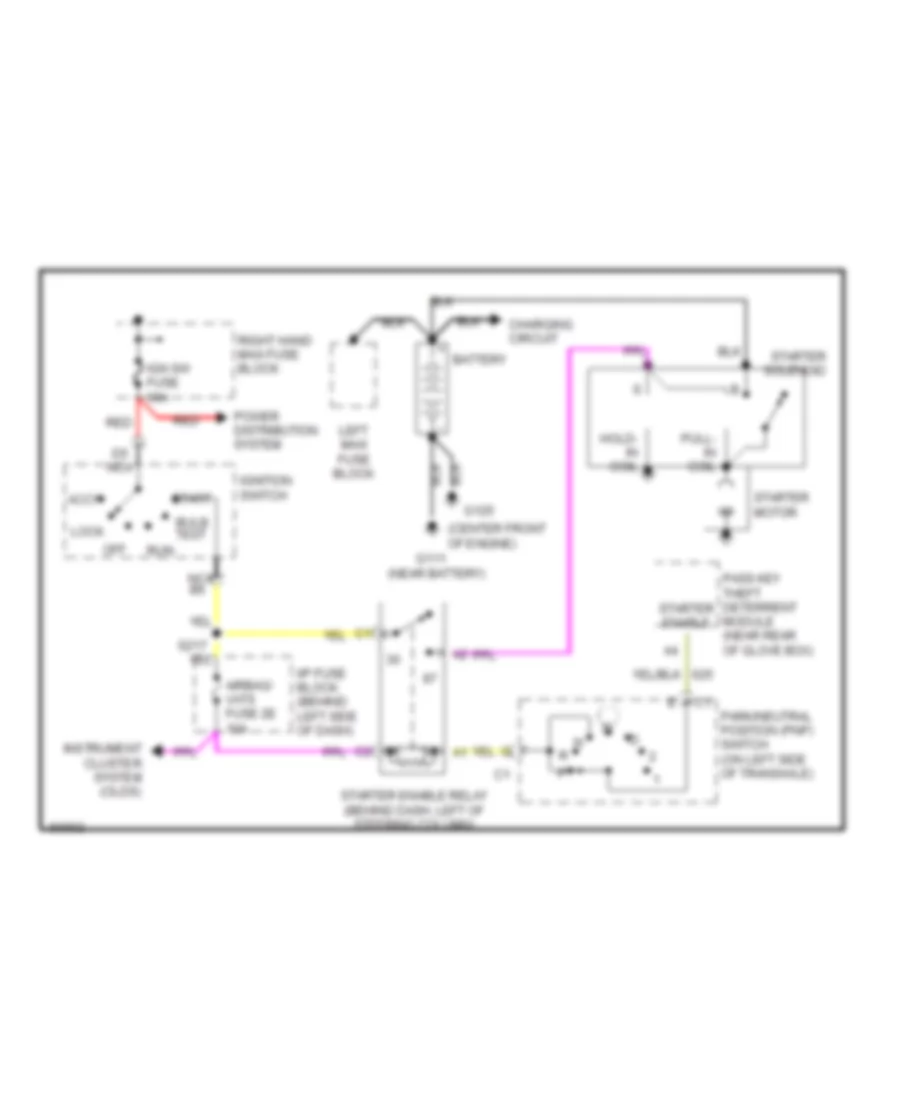
Pass-Key Wiring Diagram for Oldsmobile LSS 1997
List of elements for Pass-Key Wiring Diagram for Oldsmobile LSS 1997:
- (buick & pontiac w/ ua6)
- (olds) (pont & buic)
- Accy
- Bat
- Bulb test
- C202
- Crnk airbag/ vats fuse 1a 10a
- E12
- E13
- Enable out
- Enable relay (behind left side of i/p, above fuse box)
- Fuel enable
- G101 (right front fender)
- Ground
- Hot at all times
- Hot in run, bulb
- Hot in start
- I/p fuse block
- Ign
- Ignition key
- Ignition key lock cylinder
- Ignition switch
- Ind cntrl
- Ind control
- Information center (buick w/ ub3)
- Instrument cluster (all except buick w/ ub3)
- Key res in
- Lock
- Misc/rdo/ clstr fuse 9c (buick & pontiac) 10a
- Nca
- Off
- Park/neutral position switch
- Passkey ii decoder module (behind right side of i/p)
- Pcm fuse 8 (olds)
- Pcm/ vats fuse 4 20a
- Pnk
- Powertrain control module (left front of engine compt)
- Red
- Remote function actuator module (behind right side of i/p)
- Resistor pellet
- Right maxi fuse block (right rear of engine compt)
- Rly cntrl
- Run
- S217
- S233 s207
- S266 (body harn, 37 cm from remote function actuator breakout)
- S270
- Security indicator
- Start
- Starter solenoid
- Test or start
- Vats fuse 1a 10a
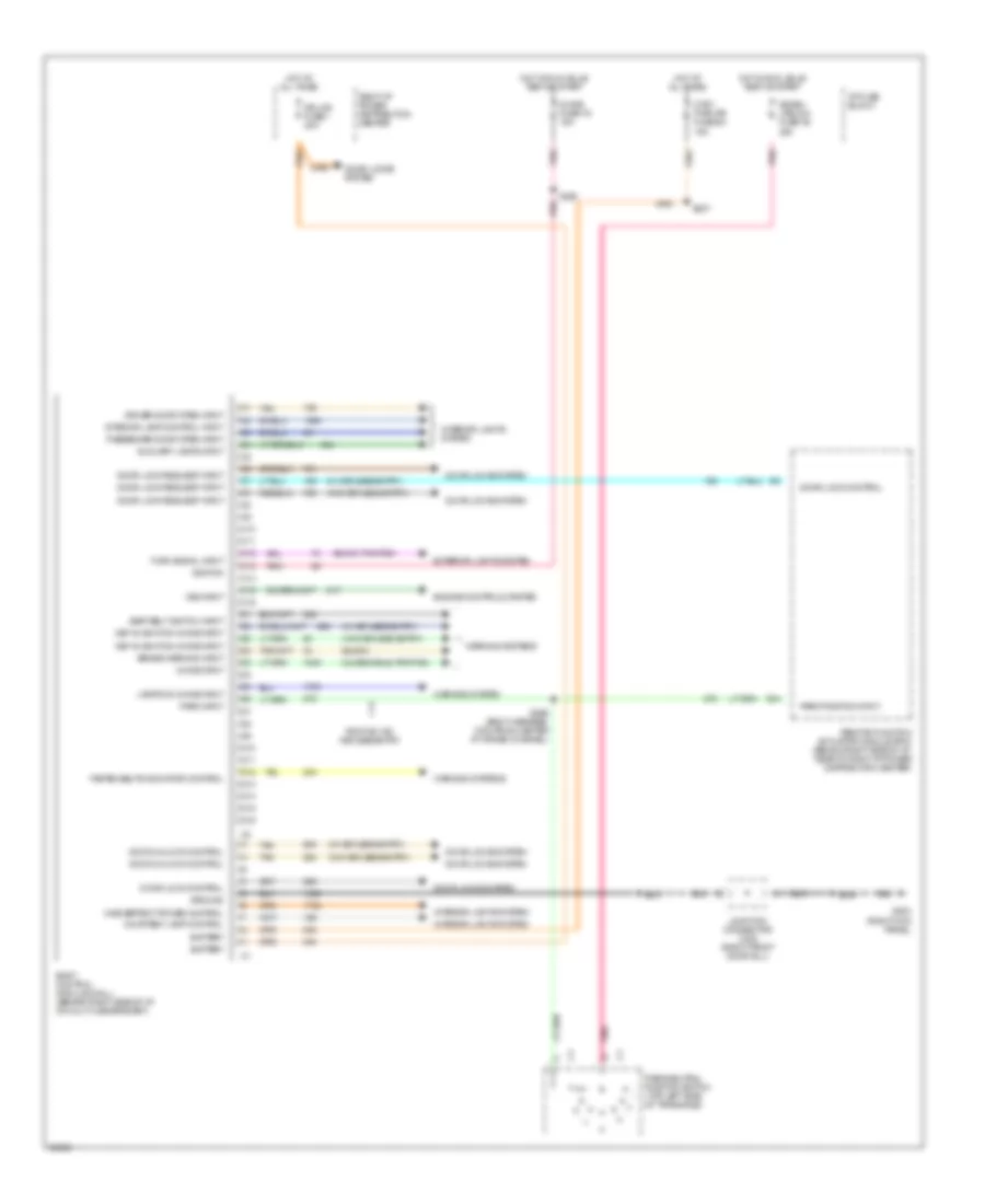
BODY COMPUTER
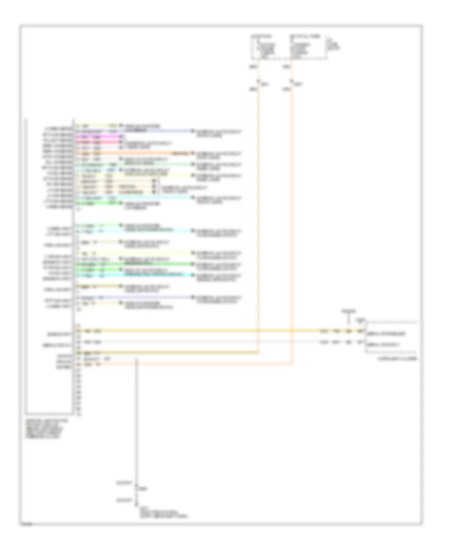
Body Computer Wiring Diagrams for Oldsmobile LSS 1997
List of elements for Body Computer Wiring Diagrams for Oldsmobile LSS 1997:
- (buick)
- (buick, pontiac)
- (oldsmobile, pontiac)
- (w/ keyless entry)
- (w/o keyless entry)
- Auxiliary lamps input
- Battery
- Body control module (mall) (behind right side of i/p, on multi-use bracket)
- Brake warning input
- C10
- C11
- C12
- C13
- C14
- C15
- C16
- Chime fuse 1d 15a
- Chime input
- Courtesy lamp control
- Ctsy pwr mir fuse 6a 15a
- D10
- D11
- D12
- D13
- D14
- D15
- D16
- Door lock control
- Door lock request input
- Door locks system
- Door unlock control
- Dr lks fuse 1 20a
- Driver door open input
- E14
- Engine controls system
- Exterior lights system
- Fasten belts indicator control
- G203 (right kick panel)
- Ground
- Hot at all times
- Hot in run, bulb test or start
- I/p fuse block
- Ignition
- Inadvertent power control
- Interior lamp control input
- Interior lights system
- Junction connector c332 (right front door sill)
- Key-in-ignition chime input
- Lamps on chime input
- Park input
- Park position input
- Park/neutral position switch (top left side of transaxle)
- Passenger door open input
- Pnk
- Pontiac w/o keyless entry
- Remote function actuator module (rfa) (behind right side of i/p, near to right i/p power distribution center)
- Right i/p power distribution center
- S208
- S237
- S296 (body harness, 13cm from center i/p cross channel)
- S307
- S308
- Seat belt switch input
- Sig/bu/ lps/lcm fuse 1b 20a
- Tan
- Turn signal input
- Vss input
- Warning system
- Warning systems
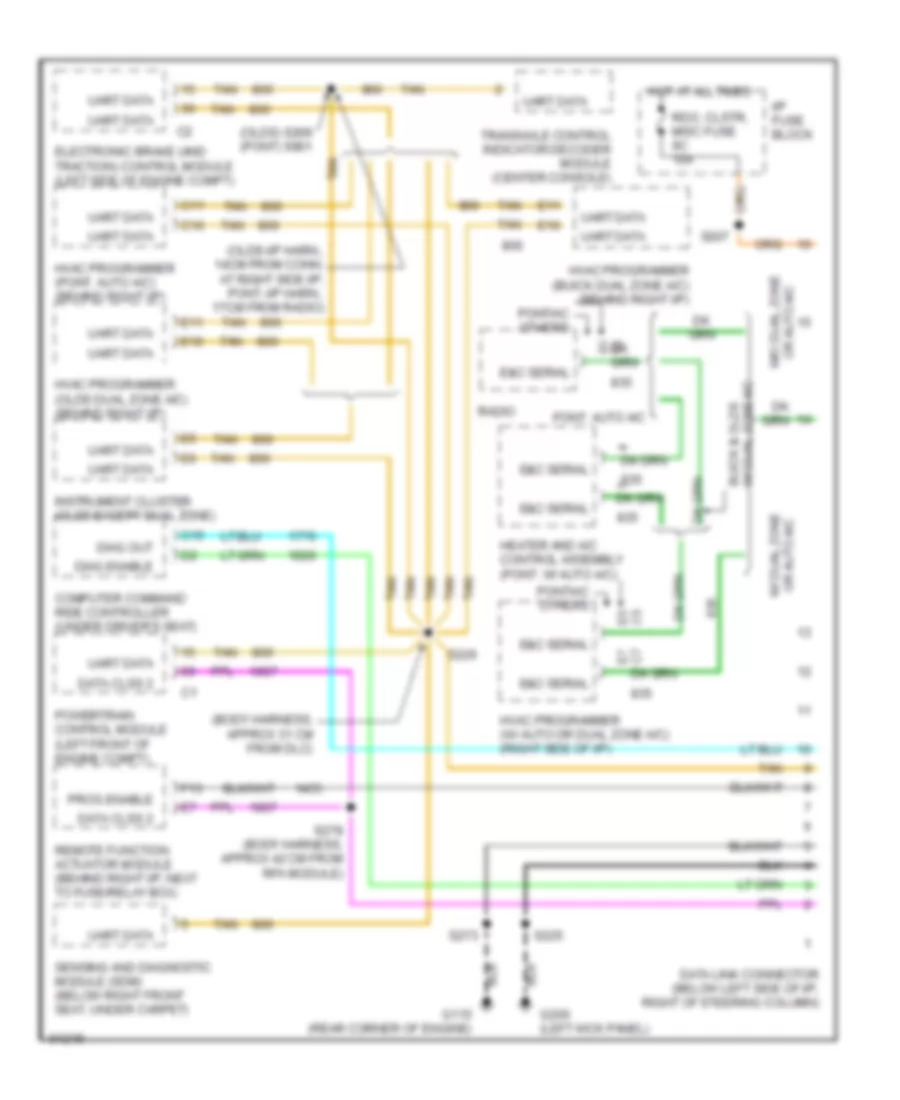
COMPUTER DATA LINES
Computer Data Lines for Oldsmobile LSS 1997
List of elements for Computer Data Lines for Oldsmobile LSS 1997:
- (body harness, approx 31 cm from dlc)
- (olds) s209 (pont) s901
- (olds-i/p harn., 14cm from conn. at right side i/p, pont.-i/p harn., 17cm from radio)
- Buick & olds w/ dual zone a/c
- C10
- C11
- C15
- Computer command ride controller (under driver's seat)
- Data clss 2
- Data link connector (below left side of i/p, right of steering column)
- Diag enable
- Diag out
- E&c serial
- E10
- E11
- E5 c5
- Electronic brake (and traction) control module (left side of engine compt)
- F13
- G115 (rear corner of engine)
- G200 (left kick panel)
- Heater and a/c control assembly (pont. w/ auto a/c)
- Hot at all times
- Hvac programmer (buick dual zone a/c) (behind right i/p)
- Hvac programmer (olds dual zone a/c) (behind right i/p)
- Hvac programmer (pont. auto a/c) (behind right i/p)
- Hvac programmer (w/ auto or dual zone a/c) (right side of i/p)
- I/p fuse block
- Instrument cluster (olds except dual zone)
- Or auto a/c w/o dual zone
- Pont. auto a/c
- Pontiac others
- Powertrain control module (left front of engine compt)
- Prog enable
- Radio
- Rdo, clstr, misc fuse 9c 10a
- Remote function actuator module (behind right i/p, next to fuse/relay box)
- S207
- S225
- S226
- S273
- S278 (body harness, approx 42 cm from rfa module)
- Sensing and diagnostic module (sdm) (below right front seat, under carpet)
- Tan
- Transaxle control indicator decoder module (center console)
- Uart data
- W/ dual zone or auto a/c
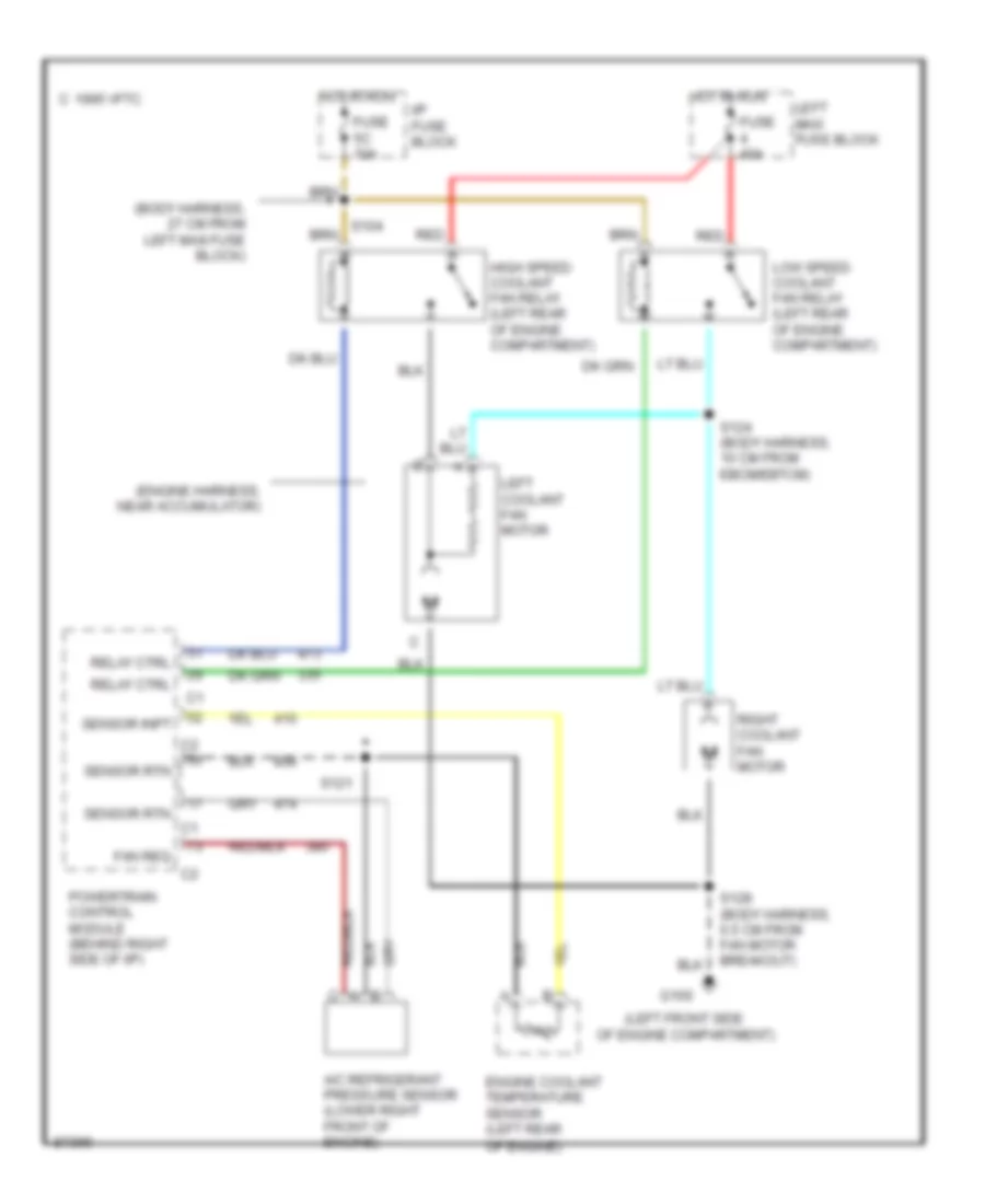
COOLING FAN
Cooling Fan Wiring Diagram for Oldsmobile LSS 1997
List of elements for Cooling Fan Wiring Diagram for Oldsmobile LSS 1997:
- (body harness, 27 cm from left maxi fuse block)
- (engine harness, near accumulator)
- (left front side
- A/c refrigerant pressure sensor (lower right front of engine)
- C 1995 vftc
- Engine coolant temperature sensor (left rear
- Fan req
- Fuse 40a
- Fuse 5c 10a
- G100
- High speed coolant fan relay (left rear of engine compartment)
- Hot in run
- I/p fuse block
- Left coolant fan motor
- Left maxi fuse block
- Low speed coolant fan relay (left rear of engine compartment)
- Of engine compartment)
- Of engine)
- Powertrain control module (behind right side of i/p)
- Red
- Relay ctrl
- Right coolant fan motor
- S121
- S124 (body harness, 10 cm from ebcm/ebtcm)
- S128 (body harness, 6.5 cm from fan motor breakout)
- Sensor inpt
- Sensor rtn
CRUISE CONTROL
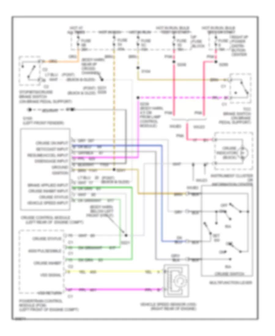
Cruise Control Wiring Diagram for Oldsmobile LSS 1997
List of elements for Cruise Control Wiring Diagram for Oldsmobile LSS 1997:
- (body harn, below left front strut)
- (body harn, near i/p cross- channel)
- (buick & olds)
- (left rear of engine compt)
- (on brake pedal support)
- (pont)
- 4000 pulses/mile
- All times
- Cruise control module
- Cruise indicator (buick)
- Cruise inhibit
- Cruise inhibit input
- Cruise on input
- Cruise status
- Cruise switch
- Disengage input
- Fuse 10a
- Fuse 1d 15a
- Fuse 5a 15a
- Fuse 5c 10a
- Fuse 6b 20a
- G100 (left front fender)
- Ground
- Hot at
- Hot in run
- Hot in run, bulb
- I/p fuse block
- Ignition
- Instrument cluster or information center
- Multifunction lever
- Off
- Pnk
- Powertrain control module (pcm) (left front of engine compt)
- R/a
- Resume/accel input
- Right i/p power distri- bution center
- S104
- S128
- S208
- S221
- S231 (pont) s228 (buick & olds)
- S239 (body harn, 4.5 cm from lamp control module)
- S241
- S299
- Set sw
- Set/coast input
- Stop/btsi/cruise brake switch
- Tcc brake switch (on brake pedal support)
- Test or start
- Vehicle speed input
- Vehicle speed sensor (vss) (right rear of engine)
- Vss return
- Vss signal
- W/u23
- W/ub3
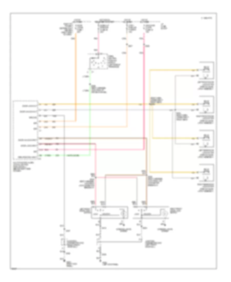
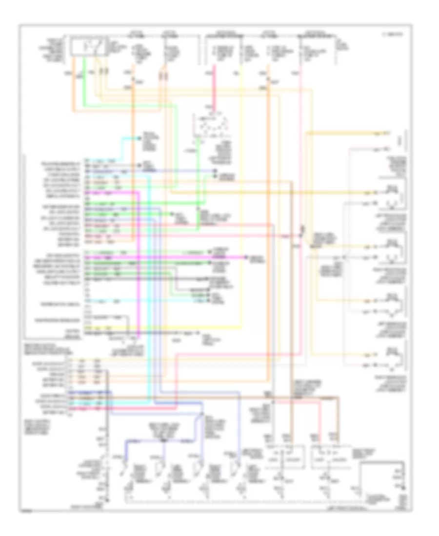
DEFOGGERS
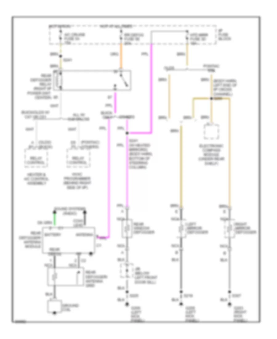
Defogger Wiring Diagram for Oldsmobile LSS 1997
List of elements for Defogger Wiring Diagram for Oldsmobile LSS 1997:
- (buick)
- (olds)
- (others)
- (pontiac)
- A b1
- A/c cruise fuse 5a 15a
- All w/ cj2 or c68
- Antenna
- Battery
- Buick only
- Buick/olds w/ c67 or c61
- C2 nca
- Coax lead
- D5 f5
- Electronic compass module (under rear shelf)
- G200 (left kick panel)
- G203 (right kick panel)
- Ground coil
- Heater & a/c control assembly
- Hot at all times
- Hot in run
- Htd mirr fuse 3d 10a
- Hvac programmer (behind right side of i/p)
- I/p fuse block
- J/b (below left front door sill)
- Left mirror defogger
- Nca
- Olds
- Others
- Pontiac sse
- Rear defog
- Rear defogger relay (right i/p power dist. center)
- Rear defogger/ antenna grid
- Rear defogger/ antenna module
- Rear window defogger
- Relay control
- Right mirror defogger
- Rr defog fuse 5e 30a
- S218
- S225
- S241
- S241 (w/ heated mirrors) (body harn, bottom of steering column)
- S307
- Sound systems (radio)
ELECTRONIC POWER STEERING
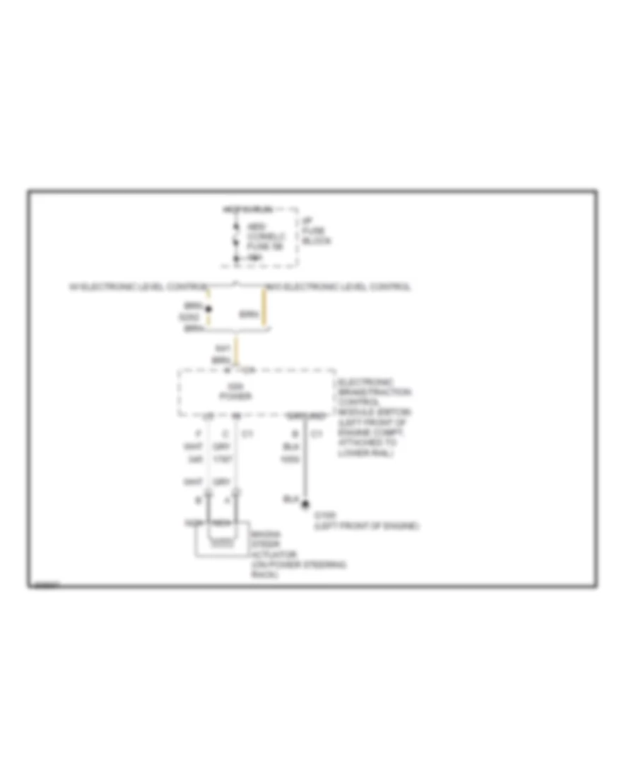
Electronic Power Steering Wiring Diagram for Oldsmobile LSS 1997
List of elements for Electronic Power Steering Wiring Diagram for Oldsmobile LSS 1997:
- Abs/ ccr/elc fuse 5b 10a
- Electronic brake/traction control module (ebtcm) (left front of engine compt, attached to lower rail)
- G100 (left front of engine)
- Ground
- Hot in run
- I/p fuse block
- Ign power
- Magna steer actuator (on power steering rack)
- Nca
- S262
- W/ electronic level control
- W/o electronic level control
ELECTRONIC SUSPENSION
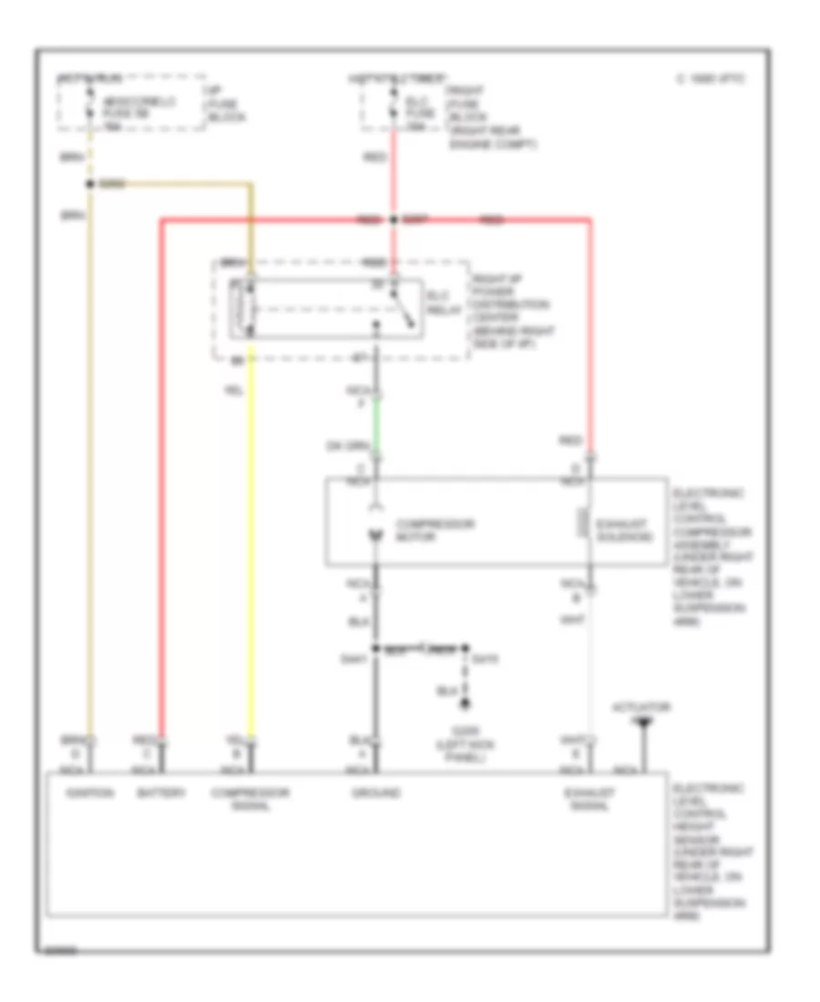
Electronic Suspension Wiring Diagram for Oldsmobile LSS 1997
List of elements for Electronic Suspension Wiring Diagram for Oldsmobile LSS 1997:
- Abs/ccr/elc fuse 5b 10a
- Actuator arm
- Battery
- C 1995 vftc
- C nca
- Compressor motor
- Compressor signal
- D nca
- Elc
- Elc fuse 30a
- Electronic level control compressor assembly (under right rear of vehicle, on lower suspension arm)
- Electronic level control height sensor (under right rear of vehicle, on lower suspension arm)
- Exhaust signal
- Exhaust solenoid
- G200 (left kick panel)
- Ground
- Hot at all times
- Hot in run
- I/p fuse block
- Ignition
- Nca
- Nca f
- Red
- Relay
- Right fuse block (right rear engine compt)
- Right i/p power distribution center (behind right side of i/p)
- S262
- S297
- S415
- S441
ENGINE PERFORMANCE
3.8L
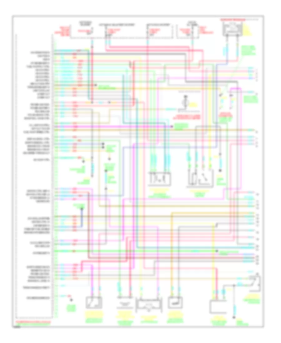
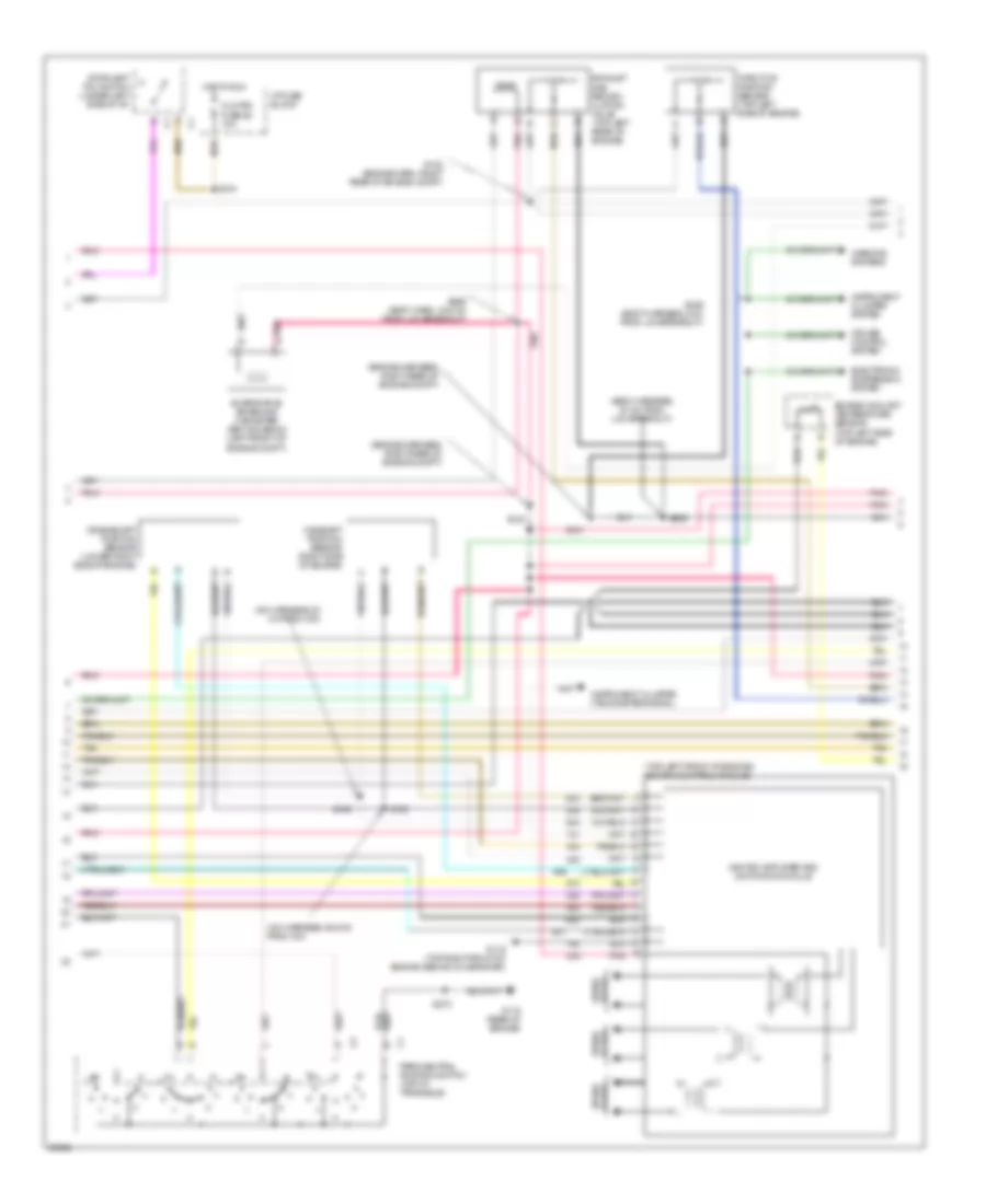
3.8L (VIN 1), Engine Performance Wiring Diagrams (1 of 3) for Oldsmobile LSS 1997
List of elements for 3.8L (VIN 1), Engine Performance Wiring Diagrams (1 of 3) for Oldsmobile LSS 1997:
- (body harn, 31.5 cm from data link connector)
- (body harn, 42.5 cm from rfa module)
- (rear of engine)
- 18x crank pos in
- 5v ref out
- A/c comp ctrl
- A/c request in
- A/t input shaft speed sensor
- A/t iss sensor hi
- A/t iss sensor lo
- Air conditioning system
- Anti-lock brakes system
- Anti-theft system
- Automatic transaxle
- Boost sol valve ctrl
- Brake/tcc sw in
- Cam pos in
- Check engine
- Cooling fans system
- Cruise control system
- Cruise engaged sig
- Data link connector (under left side of i/p)
- Delivered torque out
- Dlc class 2 data
- Egr valve sol ctrl
- Electronic suspension system
- Engine cool fan #1
- Engine cool fan #2
- Engine data sens grd
- Engine oil level in
- Engine oil level switch (center front of engine)
- Evap emissions canister purge vacuum switch (left front of engine compt)
- Evap purge diag sw
- Evap purge sol ctrl
- Evaporative emissions canister purge valve (center rear of engine)
- Fuel pump fuse 6 20a
- Fuel pump relay (i/p relay center)
- Fuel pump rly ctrl
- Fuel pump speed ctrl
- G115
- G115 (rear of engine)
- Hot at all times
- Hot in run or start
- Hot in run, bulb test or start
- Iac control
- Icm module bypass
- Idle air control (iac) valve (on side of throttle assembly)
- Ign
- Ignition ctrl in
- Ignition ctrl ref hi
- Ignition ctrl ref lo
- Instrument cluster or information center
- Intake air temperature (iat) sensor (left side of engine compt)
- Maf sensor in
- Mass air flow sensor (top left side of engine)
- Mil lamp control
- Misc eng fuse 5 20a
- Pass-key fuel enable
- Pcm fuse 8 20a
- Pcm ground
- Pcm/vats fuse 4 20a
- Pnk
- Power (battery)
- Power (ignition)
- Powertrain control module (left front of engine compt)
- Red
- Right i/p power distribution center
- Right maxi fuse block
- S110
- S130
- S226
- S233
- S273
- S278
- S439
- Tan
- Tcc solenoid ctrl
- Torque request in
- Trans range sw 'a'
- Trans range sw parity
- Uart data link
- Vehicle speed sensor (on transaxle)
- Vss in
- Vss out-4000 ppm
- Vss return
- Wot out to ccr
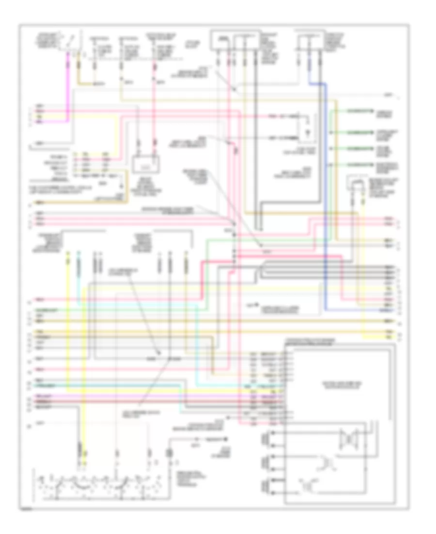
3.8L (VIN 1), Engine Performance Wiring Diagrams (2 of 3) for Oldsmobile LSS 1997
List of elements for 3.8L (VIN 1), Engine Performance Wiring Diagrams (2 of 3) for Oldsmobile LSS 1997:
- (engine harn, right rear of engine compt)
- (engine harness, right rear of engine compt)
- (icm harness, 20 cm from icm)
- (icm harness, 26.5 cm from icm)
- (top right front of engine) ignition control module
- Auto a/c cruise fuse 5a 15a
- Boost control solenoid (front of engine on fuel rail)
- Camshaft position sensor (right side of engine)
- Clg fan fuse 5c 10a
- Crankshaft position sensor (lower right side of engine)
- Cruise control system
- Electronic suspension system
- Engine coolant temperature sensor (top left side of engine)
- Exhaust gas recirc- ulation valve (top left front of engine)
- Feed out
- Fuel pump (top of fuel tank)
- Fuel pump speed control module (left side of luggage compt)
- G115 (rear of engine)
- G119 (top right front of engine, behind icm bracket)
- G200 (left kick panel)
- Ground
- Ground out
- Hot in run
- Hot in run, bulb test or start
- I/p fuse block
- Ignition amplifier and switching module
- Instrument cluster (tachometer signal)
- Instrument cluster system
- Nca
- Non obd ii misc eng fuse 6e 10a
- Park/neutral position switch (top of transaxle)
- Plugs spark
- Pnk
- Power in
- Pwm in
- S104
- S121
- S122 (engine harn, 10 cm from iat sensor)
- S123
- S135
- S136
- S225
- S246 (body harn, 8 cm from lcm breakout)
- S256 (body harn, 33.5 cm from lcm breakout)
- S273
- S279
- S918
- Spark plugs
- Stoplamp/ tcc switch (under left side of i/p)
- Tan
- Throttle position sensor (throttle body)
- Warning systems
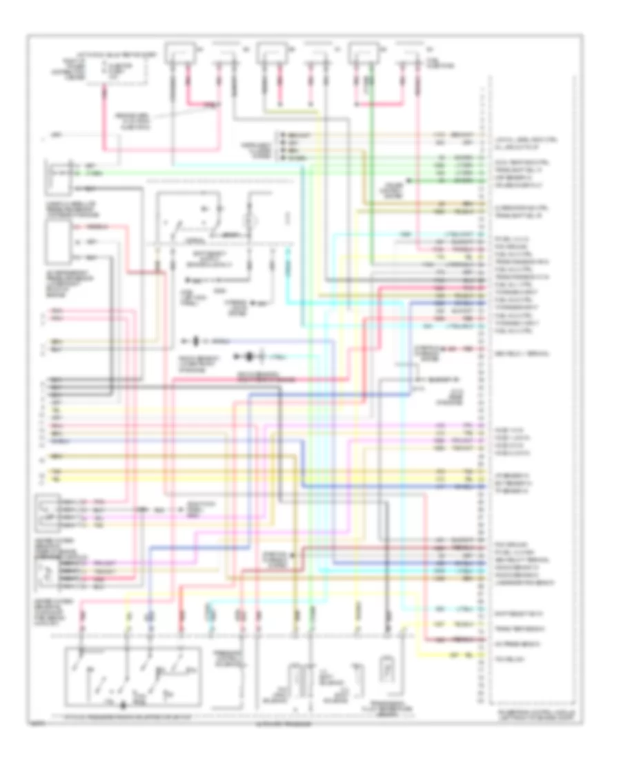
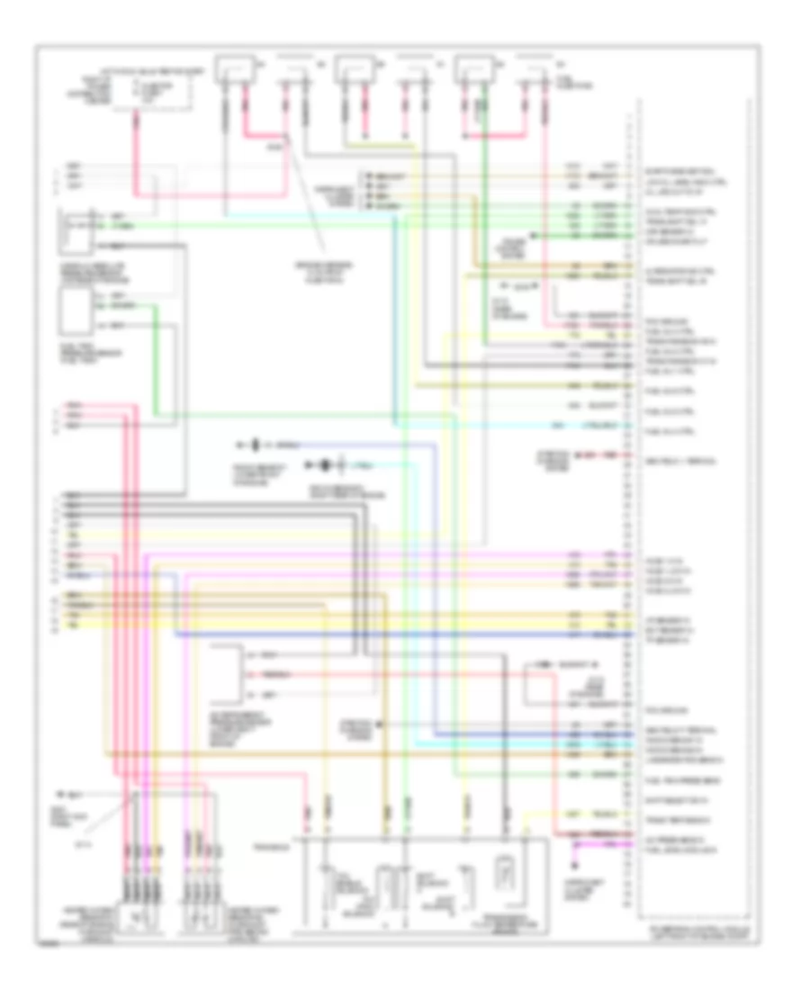
3.8L (VIN 1), Engine Performance Wiring Diagrams (3 of 3) for Oldsmobile LSS 1997
List of elements for 3.8L (VIN 1), Engine Performance Wiring Diagrams (3 of 3) for Oldsmobile LSS 1997:
- (engine harn, 12 cm from injector 6)
- (right kick panel) g203
- 1-2 shift solenoid
- 2-3 shift solenoid
- A/c press sens in
- A/c refrigerant pressure sensor (lower right front of engine)
- A/t fluid pressure manual valve position switch
- Alternator ind ctrl
- Automatic transaxle
- Cool temp indic ctrl
- Cruise control system
- Cruise inhibit out
- Ect sensor in
- Fuel inj 1 ctrl
- Fuel inj 2 ctrl
- Fuel inj 3 ctrl
- Fuel inj 4 ctrl
- Fuel inj 5 ctrl
- Fuel inj 6 ctrl
- Fuel injectors
- G115 (rear of engine)
- G200 (left kick panel)
- Gen field 'f' terminal
- Gen field 'l' terminal
- Heated oxygen sensor #1 (rear of engine, in exhaust manifold)
- Heated oxygen sensor #2 (in exhaust pipe, behind catalyst)
- Ho2s 1 hi in
- Ho2s 1 low in
- Ho2s 2 hi in
- Ho2s 2 low in
- Hot in run, bulb test or start
- Iat sensor in
- Injector fuse 7 10a
- Instrument cluster system
- Interior lights system
- Knock sens #1 in
- Knock sens #2 in
- Knock sensor 1 (lower front of engine)
- Knock sensor 2 (right rear of engine)
- Linear egr pos sens in
- Low oil level indic ctrl
- Manifold absolute pressure sensor (top rear of engine)
- Map sensor in
- Nca
- Normal
- Oil life out to i/p
- Pc sol vlv high
- Pc sol vlv lo
- Pcm ground
- Pnk
- Powertrain control module (left front of engine compt)
- Pressure control solenoid
- Red
- Red/
- Right i/p power distribution center
- S110
- S114
- S126
- S206
- Shift select sw in
- Shift select switch (bonneville only)
- Sport
- Starting/ charging system
- Tan
- Tcc (pwm) solenoid
- Tcc rel
- Tcc rel sw
- Tp sensor in
- Trans range sw 'b' in
- Trans range sw 'c' in
- Trans shift sol 'a'
- Trans shift sol 'b'
- Trans temp sens in
- Transmission fluid temperature sensor
- Tx range a input
- Tx range b input
- Tx range c input
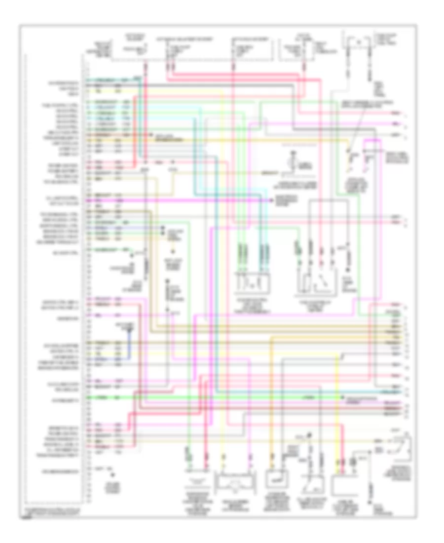
3.8L (VIN K), Engine Performance Wiring Diagrams (1 of 3) for Oldsmobile LSS 1997
List of elements for 3.8L (VIN K), Engine Performance Wiring Diagrams (1 of 3) for Oldsmobile LSS 1997:
- (body harn, 42.5 cm from rfa module)
- (body harness, 31.5 cm from data link connector)
- (right front fender)
- 18x crank pos in
- 5v ref out
- A/c comp ctrl
- A/c request in
- Air conditioning system
- Anti-lock brakes system
- Anti-theft system
- Brake/tcc sw in
- Cam pos in
- Check engine
- Cooling fans system
- Cruise control system
- Cruise engaged sig
- Data link connector (under left side of i/p)
- Delivered torque out
- Dlc class 2 data
- Egr valve sol ctrl
- Electronic suspension system
- Engine cool fan #1
- Engine cool fan #2
- Engine data sens grd
- Engine oil level in
- Engine oil level switch (center front of engine)
- Evap purge sol ctrl
- Evaporative emissions canister purge valve (center rear of engine)
- Fuel pump (top of fuel tank)
- Fuel pump fuse 6 20a
- Fuel pump relay (i/p relay center)
- Fuel pump rly ctrl
- G101
- G115 (rear of engine)
- G200 (left kick panel)
- Hot at all times
- Hot in run or start
- Hot in run, bulb test or start
- Iac control
- Icm module bypass
- Idle air control (iac) valve (on side of throttle assembly)
- Ign
- Ignition ctrl in
- Ignition ctrl ref hi
- Ignition ctrl ref lo
- Instrument cluster or information center
- Intake air temperature (iat) sensor (left side of engine compt)
- Maf sensor in
- Mass air flow sensor (top left side of engine)
- Mil lamp control
- Misc eng fuse 5 20a
- Nca
- Oil life monitor reset switch (buick only)
- Oil life reset sw
- Pass-key fuel enable
- Pcm fuse 8 20a
- Pcm ground
- Pcm/vats fuse 4 20a
- Pnk
- Power (battery)
- Power (ignition)
- Powertrain control module (left front of engine compt)
- Red
- Right i/p power distribution center
- Right maxi fuse block
- S110
- S130
- S226
- S233
- S273
- S278
- S439
- S908
- Tan
- Tcc enable sol ctrl
- Tcc solenoid ctrl
- Torque request in
- Trans range sw 'a'
- Trans range sw parity
- Uart data link
- Vehicle speed sensor (on transaxle)
- Vss in
- Vss out-4000 ppm
- Vss return
- Wot out to ccr
3.8L (VIN K), Engine Performance Wiring Diagrams (2 of 3) for Oldsmobile LSS 1997
List of elements for 3.8L (VIN K), Engine Performance Wiring Diagrams (2 of 3) for Oldsmobile LSS 1997:
- (body harness, 27 cm from lcm breakout)
- (engine harness, right rear of engine compt)
- (icm harness, 20 cm from icm)
- (icm harness, 26.5 cm from icm)
- (top left front of engine) ignition control module
- Camshaft position sensor (right side of engine)
- Clg fan fuse 5c 10a
- Crankshaft position sensor (lower right side of engine)
- Cruise control system
- Electronic suspension system
- Engine coolant temperature sensor (top left side of engine)
- Evaporative emissions cannister vent solenoid (left front of engine compt)
- Exhaust gas recirc- ulation valve (top left rear of engine)
- G115 (rear of engine)
- G119 (top right front of engine, behind icm bracket)
- Hot in run
- I/p fuse block
- Ignition amplifier and switching module
- Instrument cluster (tachometer signal)
- Instrument cluster system
- Park/neutral position switch (top of transaxle)
- Plugs spark
- Pnk
- Pnk a
- S104
- S121
- S122 (engine harn, right rear of engine compt)
- S123
- S135
- S136
- S246 (body harness, 8 cm from lcm breakout)
- S256 (body harn, 33.5 cm from lcm breakout)
- S273
- S929
- Spark plugs
- Stoplamp/ tcc switch (under left side of i/p)
- Tan
- Throttle position sensor (top left side of engine)
- Warning systems
3.8L (VIN K), Engine Performance Wiring Diagrams (3 of 3) for Oldsmobile LSS 1997
List of elements for 3.8L (VIN K), Engine Performance Wiring Diagrams (3 of 3) for Oldsmobile LSS 1997:
- (engine harness, 12 cm from injector 6)
- A/c press sens in
- A/c refrigerant pressure sensor (lower right front of engine)
- Alternator ind ctrl
- Cool temp indic ctrl
- Cruise control system
- Cruise inhibit out
- Ect sensor in
- Evap purge vent sol
- Fuel inj 1 ctrl
- Fuel inj 2 ctrl
- Fuel inj 3 ctrl
- Fuel inj 4 ctrl
- Fuel inj 5 ctrl
- Fuel inj 6 ctrl
- Fuel injectors
- Fuel level module in
- Fuel tank press sens
- Fuel tank pressure sensor (fuel tank)
- G115 (rear of engine)
- G203 (right kick panel)
- Gen field 'f' terminal
- Gen field 'l' terminal
- Heated oxygen sensor #1 (rear of engine, in exhaust manifold)
- Heated oxygen sensor #2 (in exhaust pipe, behind catalyst)
- Ho2s 1 hi in
- Ho2s 1 low in
- Ho2s 2 hi in
- Ho2s 2 low in
- Hot in run, bulb test or start
- Iat sensor in
- Injector fuse 7 10a
- Instrument cluster system
- Knock sens #1 in
- Knock sens #2 in
- Knock sensor 1 (lower front of engine)
- Knock sensor 2 (right rear of engine)
- Linear egr pos sens in
- Low oil level indic ctrl
- Manifold absolute pressure sensor (top rear of engine)
- Map sensor in
- Nca
- Oil life out to i/p
- Pcm ground
- Pnk
- Powertrain control module (left front of engine compt)
- Red
- Right i/p power distribution center
- S110
- S114
- S126
- Shift select sw in
- Shift solenoid a
- Shift solenoid b
- Starting/ charging system
- Tan
- Tcc (pwm) solenoid
- Tcc enable solenoid
- Tp sensor in
- Trans range sw 'b' in
- Trans range sw 'c' in
- Trans shift sol 'a'
- Trans shift sol 'b'
- Trans temp sens in
- Transaxle
- Transmission fluid temperature sensor
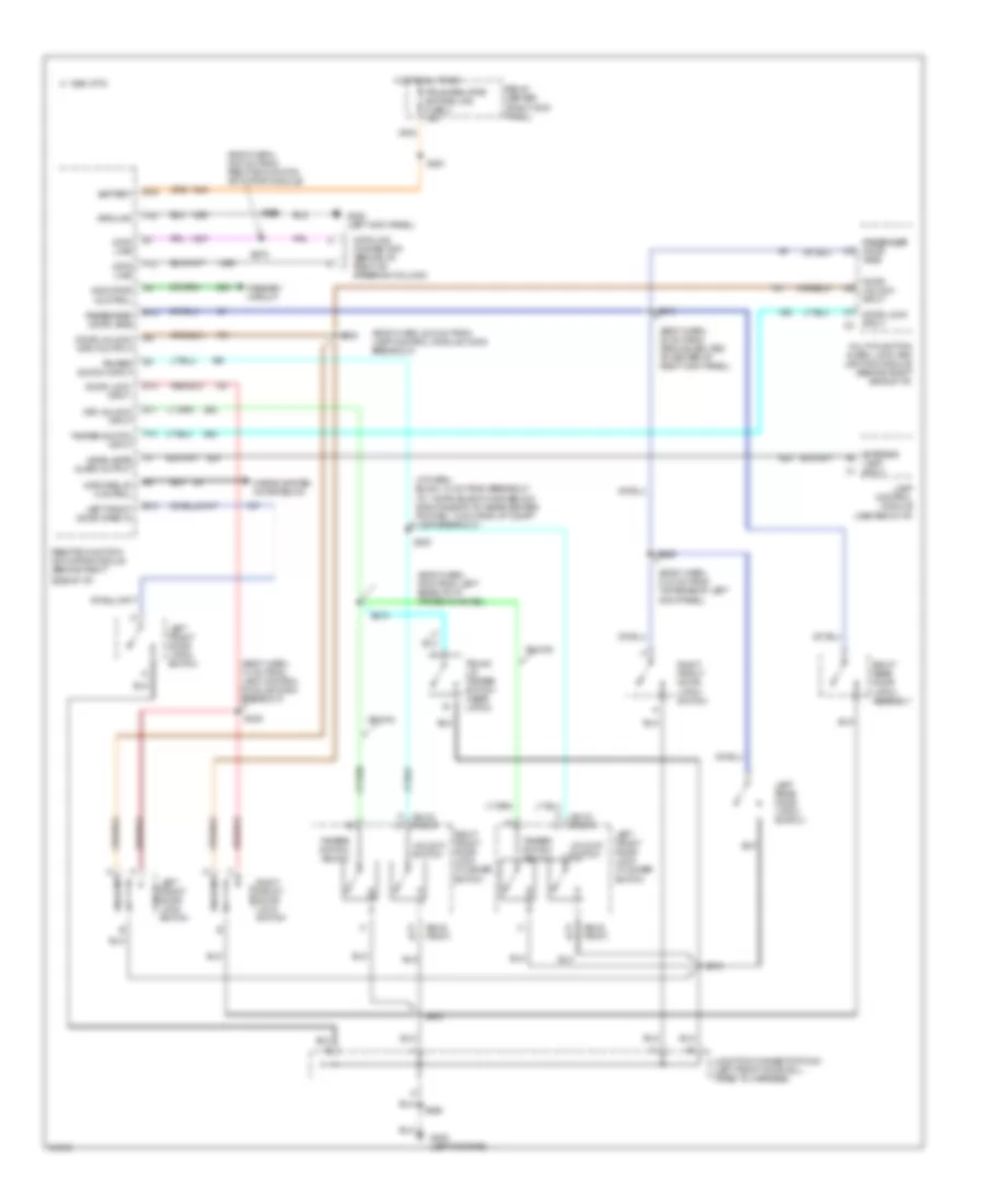
EXTERIOR LIGHTS
Adaptive Lamp Monitor Module Wiring Diagram for Oldsmobile LSS 1997
List of elements for Adaptive Lamp Monitor Module Wiring Diagram for Oldsmobile LSS 1997:
- (oldsmobile)
- (pontiac)
- Adaptive lamp monitor control module (behind left side of dash, right side of steering column)
- Auto a/c cruise fuse 5a 10a
- B/u lps sense
- Back-up lights circuit (back-up lamps)
- Back-up lights circuit (park/neutral position switch)
- Battery
- Brake sw input
- Chmsl sense
- Enable input
- Exterior lights circuit (brake lamps switch)
- Exterior lights circuit (brake switch)
- Exterior lights circuit (front lamps)
- Exterior lights circuit (headlamp switch)
- Exterior lights circuit (high mount stop lamp)
- Exterior lights circuit (rear lamps)
- Exterior lights circuit (stop lamps)
- Exterior lights circuit (turn/hazard switch)
- G101 (right front of eng compt, above right horn)
- Ground
- Headlights system (headlamp dimmer switch)
- Headlights system (low beams)
- Hi beam input
- Hi beam sense
- Hot at all times
- Hot in run
- I/p fuse block
- Ignition
- Instrument cluster
- Lf mkr sense
- Lf tn sig sense
- Lo beam input
- Lo beam sense
- Lr tn sig sense
- Lt ft sig input
- Lt rr sig input
- Misc/rdo clstr fuse 9c 10a
- Olds
- P/n sw input
- Park lps input
- Pnk
- Pontiac
- Rear lps sense
- Rf mkr sense
- Rf tn sig sense
- Rr tn sig sense
- Rt ft sig input
- Rt rr sig input
- S207
- S241
- S293
- Serial data input
- Serial data out
- Serial data request
- Stop lps sense
- Taillight sense
- Tan
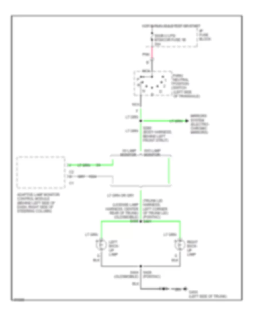
Back-up Lamps Wiring Diagram for Oldsmobile LSS 1997
List of elements for Back-up Lamps Wiring Diagram for Oldsmobile LSS 1997:
- (license lamp harness, center rear of trunk) (oldsmobile) s406
- (trunk lid harness, left corner of trunk lid) (pontiac) s481
- Adaptive lamp monitor control module (behind left side of dash, right side of steering column)
- G404 (left side of trunk)
- Hot in run, bulb test or start
- I/p fuse block
- Left back- up lamp
- Mirrors system (electro- chromic mirrors)
- Nca
- Park/ neutral position switch (left side of transaxle)
- Pnk
- Right back- up lamp
- S280 (body harness, behind left front strut)
- S400
- S404 (oldsmobile)
- S428 (pontiac)
- Sig/b-u lps/ btsi/cor fuse 1b 20a
- W/ lamp monitor
- W/o lamp monitor
Exterior Lamps Wiring Diagram, with Adaptive Lamp Monitor (1 of 2) for Oldsmobile LSS 1997
List of elements for Exterior Lamps Wiring Diagram, with Adaptive Lamp Monitor (1 of 2) for Oldsmobile LSS 1997:
- (body harness, 11cm from end of right i/p cross-channel) s281
- Adaptive lamp monitor control module (behind dash, right side of steering column)
- Brake sw input
- Center high mounted stop lamp
- Chmsl sense
- G100 (left front of engine compartment)
- G101 (right front of engine compartment)
- G203 (right kick panel)
- G404 (left rear side of trunk)
- Head
- Head/ park lamp switch
- Hot at all times
- I/p fuse block
- Interior lights system
- Lamp control module (center of dash)
- Lcm/hdlp circuit breaker 20a
- Left front park/ turn lamp
- Left front side marker lamp b
- Left maxi- fuse block
- Lf mkr sense
- Lf tn sig sense
- Lr tn sig sense
- Lt ft sig input
- Lt rr sig input
- Off
- Park
- Park lps input
- Parklamp relay (position k) (right i/p power distribution center)
- Pk/int lps fuse 6c 15a
- Pnk
- Rear lps sense
- Red
- Remote function actuator module (behind right side of dash)
- Rf mkr sense
- Rf tn sig sense
- Right front park/ turn lamp
- Right front side marker lamp b
- Rr tn sig sense
- Rt ft sig input
- Rt rr sig input
- S108
- S128
- S201
- S202
- S204 (body harness, 11cm from ipc (cluster) connectors)
- S219 (body harness, behind left front strut)
- S236 (body harn, 35cm from adaptive lamp monitor module)
- S283 (body harness, 4cm from end of right i/p cross-channel)
- S308
- S400
- Tail lmps sense
Exterior Lamps Wiring Diagram, with Adaptive Lamp Monitor (2 of 2) for Oldsmobile LSS 1997
List of elements for Exterior Lamps Wiring Diagram, with Adaptive Lamp Monitor (2 of 2) for Oldsmobile LSS 1997:
- A11
- Brk/hzrd lps fuse 6b 20a
- C16
- Cruise/ shift interlock brake switch (on brake pedal support) c2
- D16
- G200 (left kick panel)
- G404 (left rear side of trunk)
- Hazard flasher (behind i/p, right of steering column support)
- Hazard switch
- Hot at all times
- Hot in run, bulb
- I/p fuse block
- Instrument cluster
- Left rear side marker lamp
- Left tail/ stop/ turn lamps
- Left turn indicator
- Left turn switch
- License lamps
- Nca
- Pnk
- Right rear side marker lamp
- Right tail/ stop/ turn lamps
- Right turn indicator
- Right turn switch
- S225
- S232 (body harn, 12cm from center i/p cross-channel)
- S235 (body harn, 20cm from center i/p cross-channel)
- S400
- S404
- S416 (body harness, left rear corner of trunk)
- S433 (license lamp harness, center rear of trunk)
- Sig/b-u lps btsi/cor fuse 1b 20a
- Test or start
- Turn flasher (attached to sound insulator)
- Turn/ hazard switch assembly
Exterior Lamps Wiring Diagram, without Adaptive Lamp Monitor (1 of 2) for Oldsmobile LSS 1997
List of elements for Exterior Lamps Wiring Diagram, without Adaptive Lamp Monitor (1 of 2) for Oldsmobile LSS 1997:
- (body harness, 11cm from ipc (cluster) connectors) s204
- G100 (left front of engine compartment)
- G101 (right front of engine compartment)
- G203 (right kick panel)
- Head
- Head/ park lamp switch
- Hot at all times
- I/p fuse block
- Interior lights system
- Lamp control module (center of dash)
- Lcm/hdlp circuit breaker 20a
- Left front park/ turn lamp
- Left front side marker lamp b
- Left maxi- fuse block
- Off
- Park
- Parklamp relay (position k) (right i/p power distribution center)
- Pk/int lps fuse 6c 15a
- Red
- Remote function actuator module (behind right side of dash)
- Right front park/ turn lamp
- Right front side marker lamp b
- S108
- S128
- S201
- S202
- S308
Exterior Lamps Wiring Diagram, without Adaptive Lamp Monitor (2 of 2) for Oldsmobile LSS 1997
List of elements for Exterior Lamps Wiring Diagram, without Adaptive Lamp Monitor (2 of 2) for Oldsmobile LSS 1997:
- A11
- Brk/hzrd lps fuse 6b 20a
- C16
- Center high mounted stop lamp
- Cruise/ shift interlock brake switch (on brake pedal support) c2
- D16
- G200 (left kick panel)
- G404 (left rear side of trunk)
- Hazard flasher (behind i/p, right of steering column support)
- Hazard switch
- Hot at all times
- Hot in run, bulb
- I/p fuse block
- Instrument cluster
- Left rear side marker lamp
- Left tail/ stop/ turn lamps
- Left turn indicator
- Left turn switch
- License lamps
- Pnk
- Right rear side marker lamp
- Right tail/ stop/ turn lamps
- Right turn indicator
- Right turn switch
- S225
- S232 (body harn, 12cm from center i/p cross-channel)
- S235 (body harn, 20cm from center i/p cross-channel)
- S400
- S404
- S417 (body harness, left rear corner of trunk)
- S433 (license lamp harness, center rear of trunk)
- Sig/b-u lps btsi/cor fuse 1b 20a
- Test or start
- Turn flasher (attached to sound insulator)
- Turn/ hazard switch assembly
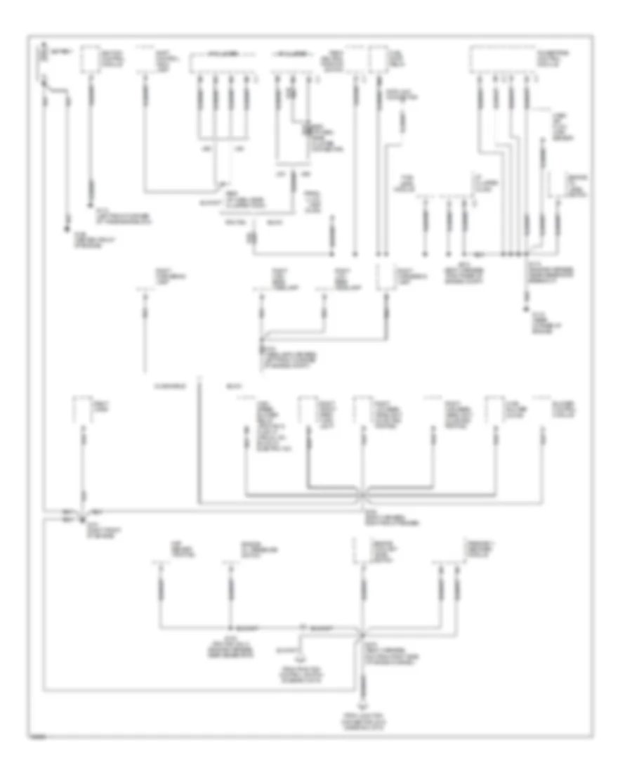
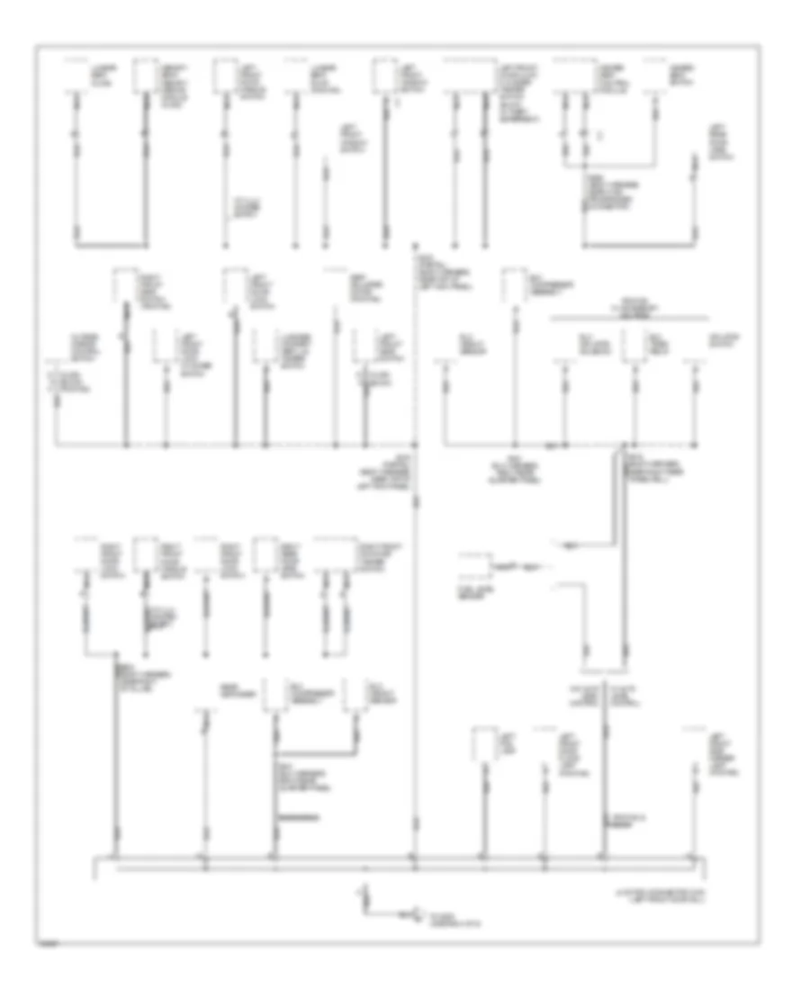
GROUND DISTRIBUTION
Ground Distribution Wiring Diagram (1 of 6) for Oldsmobile LSS 1997
List of elements for Ground Distribution Wiring Diagram (1 of 6) for Oldsmobile LSS 1997:
- A17
- Battery
- Blower control module
- Buick
- Data link connector
- Engine coolant level switch
- Engine oil level switch
- Engine oil pressure switch
- From junction connector c215 (diagram 2 of 6)
- From traction control switch (diagram 2 of 6)
- Fuel level module
- Fuel pump relay
- G101 (right front of engine)
- G110 (left front corner of the engine block)
- G115 (rear corner of engine)
- G125 (center, front of engine)
- High speed blower relay (pontiac & olds w/ manual a/c, buick w/ electric a/c)
- Hvac blower motor
- I/p cluster
- I/p cluster (olds)
- Ignition control module
- Map sensor (pontiac)
- Mass air flow (maf) sensor
- N86
- Oldsmobile
- Park/ neutral position switch
- Pass-key ii decoder module
- Pontiac
- Powertrain control module
- Prndl illum. lamp (olds)
- Right cornering lamp
- Right front park/ turn light
- Right high beam headlamp
- Right high beam headlight (olds and pontiac)
- Right horn
- Right low beam headlamp
- Right low beam headlight (olds and pontiac)
- S100 (pontiac only) (engine harness, near generator)
- S108 (body harness, right front fender)
- S110 (engine harness, near generator breakout)
- S151 (headlamp harness, left front corner of engine compt)
- S270 (body harness, 8cm from right side i/p cross channel)
- S273 (body harness, right rear of engine compt)
- S906 (i/p harn, near cluster connector)
- Shift control indic lamp
- U50
- Ub3
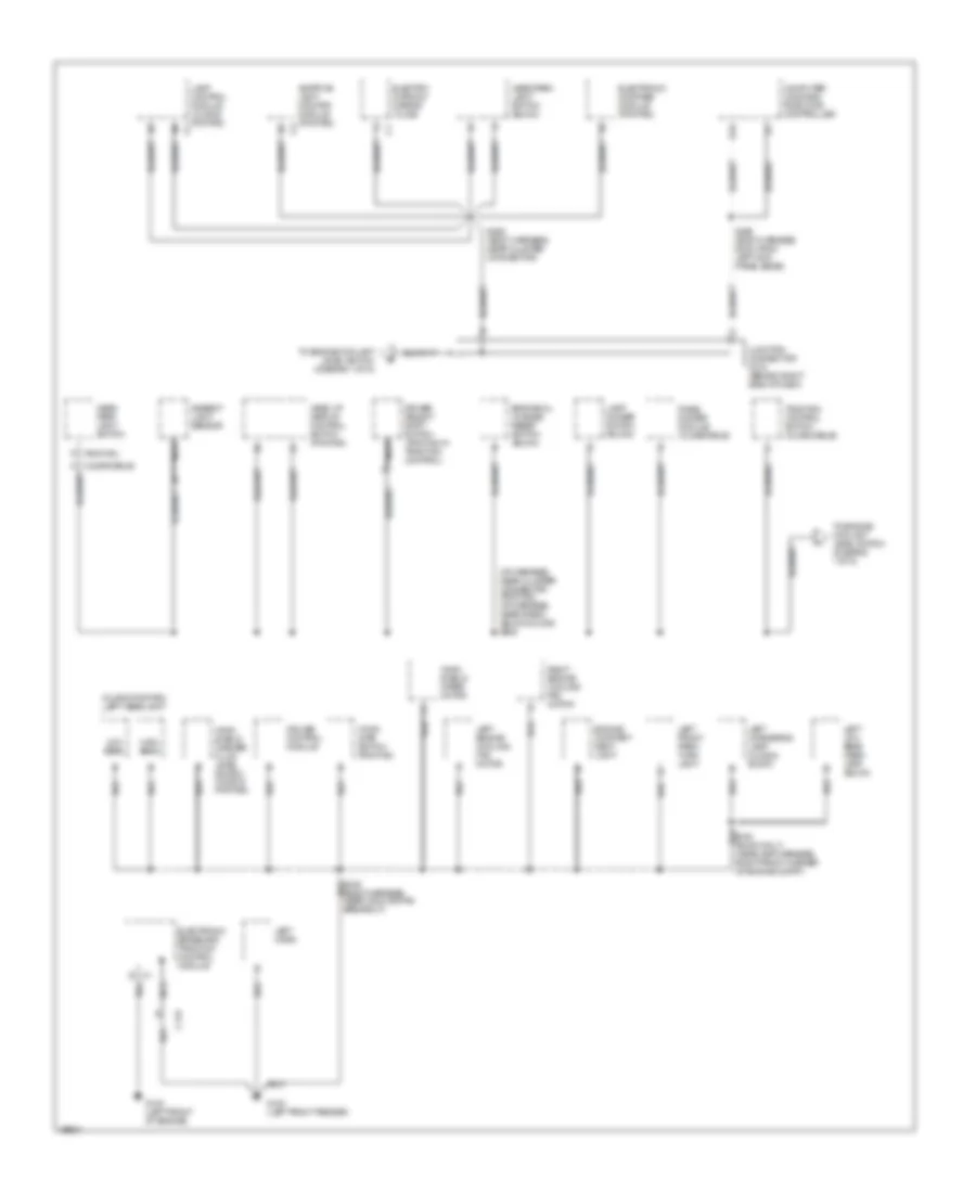
Ground Distribution Wiring Diagram (2 of 6) for Oldsmobile LSS 1997
List of elements for Ground Distribution Wiring Diagram (2 of 6) for Oldsmobile LSS 1997:
- (i/p harness, near cluster connector (pontiac) (i/p harness, near radio) (buick & olds) s908
- (olds & pontiac) left headlight
- Adaptive light monitor module (pontiac)
- Ambient light sensor
- B c1
- C119
- Computer command ride (ccr) controller
- Cruise control module
- D16
- Driver select shift switch (pontiac w/ traction control)
- Electro- chromic mirror (olds)
- Electronic brake and traction control module
- Electronic compass module (pontiac)
- Engine compart- ment light
- Engine oil change reset switch (buick)
- G100 (left front fender)
- G100 (left front of engine)
- Head up display control switch (pontiac)
- Head/ park light switch
- Head/park light switch (buick)
- High beam
- Hood ajar switch (pontiac)
- Junction connector c215 (behind right side of dash)
- K (oldsmobile)
- Lamp control module (olds & pontiac)
- Lamp dimmer switch (buick)
- Left cornering lamp (olds & buick)
- Left engine cooling fan motor
- Left front park/ turn light
- Left horn
- Left low beam head- lamp (buick)
- Low beam
- Nca
- P (pontiac)
- Panel dimmer module (oldsmobile)
- Right engine cooling fan motor
- S292 (body harness, 63cm from left kick panel edge)
- S293 (body harness, near cluster connector)
- To engine coolant level switch (diagram 1 of 6)
- Traction control switch (oldsmobile)
- Wind- shield washer fluid level switch (olds & pontiac)
- Wind- shield wiper motor
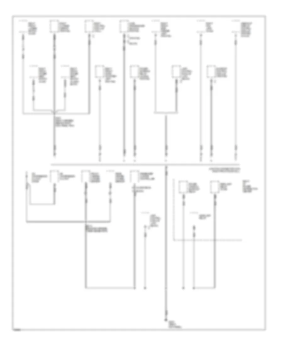
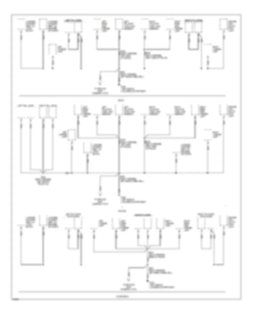
Ground Distribution Wiring Diagram (3 of 6) for Oldsmobile LSS 1997
List of elements for Ground Distribution Wiring Diagram (3 of 6) for Oldsmobile LSS 1997:
- (buick)
- (pontiac)
- A or b
- A/c compressor clutch
- A/c compressor clutch diode
- A10
- Body control module (mall)
- D (oldsmobile)
- Front heated oxygen sensor
- G2o3 (right kick panel)
- H (buick)
- H86
- Headlamp relay
- Heads-up display control module (pontiac w/ hud)
- Hvac programmer (buick & pontiac)
- J86
- Junction connector c332 (right front door sill)
- K86
- Lamp control module (lcm) (buick)
- Nca
- Parklamp relay (olds)
- Passenger climate controller
- Power antenna relay (olds & pontiac)
- Power window/ sunroof relay
- Rear heated oxygen sensor
- Right fog lamp (olds)
- Right front door courtesy lamp (pontiac)
- Right front lumbar switch (olds)
- Right front power seat switch (olds & buick)
- Right front power seat switch (olds)
- Right front side marker lamp (pontiac)
- Right i/p power distribution center
- Right outside mirror (pontiac)
- S307 (body harness, behind right kick panel trim)
- Sunroof control module (pontiac)
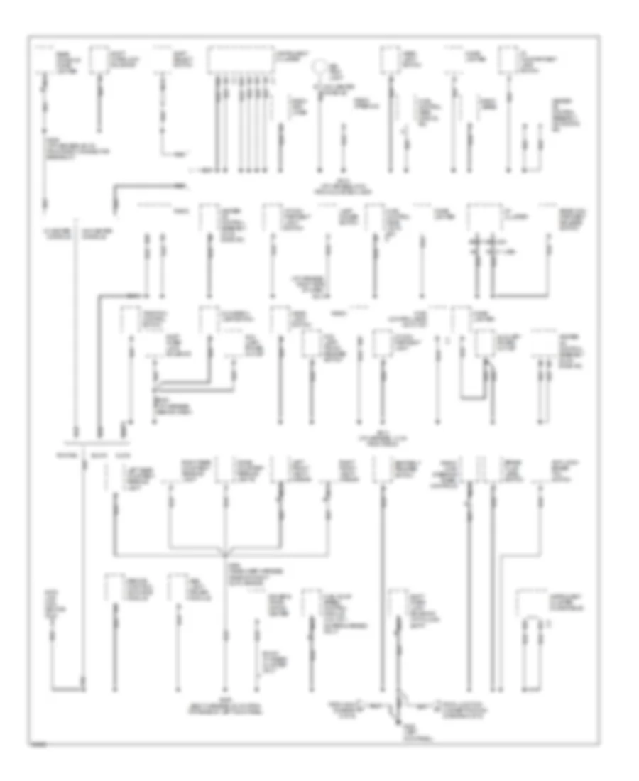
Ground Distribution Wiring Diagram (4 of 6) for Oldsmobile LSS 1997
List of elements for Ground Distribution Wiring Diagram (4 of 6) for Oldsmobile LSS 1997:
- (i/p harness, behind dash)
- (i/p harness, right side of dash) s213
- (ub3) c1
- 6 of 6)
- A19
- Abs light driver module
- Anti-lock/ brake/ tcc switch
- Ash tray light
- Aux- iliary power outlet
- Auxiliary power outlet
- B15
- B8 (u23)
- Brake fluid level switch
- Buick
- Buick w/ gages cluster only
- Cigar lighter
- Data link con- nector (dlc)
- Dome/ courtesy reading lights
- Driver's infor- mation center
- E11
- E12
- E16
- F16
- Fog lamp/ trunk release switch
- From g404 (diagram c
- From junction connector c340 (diagram 5 of 6)
- Fuel pump speed control module (3.8l vin 1 (supercharged) only)
- G200 (left kick panel)
- Glove box lamp switch
- Head- light switch
- Heater- a/c control assembly (automatic a/c)
- Heater- a/c control assembly (dual zone a/c)
- Hvac control head (auto a/c)
- Hvac control head (auto a/c) c2
- Hvac control head (manual a/c)
- I/p cluster
- I/p com- partment light
- I/p com- partment light switch
- I/p compartment lamp switch
- Instrument cluster
- Instrument cluster (oldsmobile)
- Lamp dimmer switch
- Left front vanity mirror
- Left rear courtesy/ reading light
- Nca
- Olds
- Pontiac
- Radio
- Radio (base)
- Radio (premium)
- Radio amp- lifier
- Radio/ hvac steering wheel controls
- Rear com- partment release switch
- Rear console cigar lighter
- Remote function actuator module
- Right front vanity mirror
- Right rear courtesy/ reading light
- S206 (i/p harness, 60 cm from radio connector breakout)
- S213 (i/p harness, 13 cm from radio)
- S213 (i/p harness, 6 cm from glove box lamp)
- S225 (body harness, 50 cm from top edge of left kick panel)
- S338 (headliner harness, near day/night auto mirror)
- Seat belt release switch
- Shift inter- lock solenoid
- Shift inter- lock solenoid (w/ column shift)
- Shift interlock solenoid
- Shift select switch
- Traction control switch
- W/ center console
- W/o center console
Ground Distribution Wiring Diagram (5 of 6) for Oldsmobile LSS 1997
List of elements for Ground Distribution Wiring Diagram (5 of 6) for Oldsmobile LSS 1997:
- (body harness, near right "b" pillar)
- (buick)
- (olds) d a (buick) (pontiac)
- (w/ illu- minated entry)
- Elc compressor assembly
- Elc height sensor
- Elc inflator solenoid
- Elc timer relay
- Fuel level sender
- Heated seat control module
- Heated seat switch
- Inflator switch
- Junction connector c340 (left front door sill)
- Left fog lamp
- Left front door flood lamp (pontiac)
- Left front door handle switch
- Left front door lock cylinder switch
- Left front door lock cylinder tamper switch (buick w/ theft deterrent)
- Left front door lock switch
- Left front seat switch
- Left front side marker lamp (pontiac)
- Left front window switch
- Left rear door jamb switch
- Luggage compart- ment lid tamper switch
- Lumbar seat (olds)
- Lumbar seat pump (pontiac)
- Memory seat/ memory mirror module (olds)
- Minated entry)
- Nca
- Oldsmobile
- Outside mirror control switch
- Pontiac & buick
- Pontiac w/ accessory inflator
- Rear defogger
- Right front door handle switch
- Right front door key tamper switch
- Right front door lock switch
- Right front seat switch (pontiac)
- Right rear door jamb switch
- S218 (partial) (body harness, near top of left kick panel)
- S268 (body harness, near hvac programmer connector)
- S441 (elc harness, right rear quarter panel)
- Seat adjuster motor (pontiac)
- To g200 (diagram 4 of 6)
- W/ auto level control
- W/o auto level control
Ground Distribution Wiring Diagram (6 of 6) for Oldsmobile LSS 1997
List of elements for Ground Distribution Wiring Diagram (6 of 6) for Oldsmobile LSS 1997:
- Backup lamps
- Buick
- Center high mount stop light
- G402 (left side of luggage compartment)
- Left license lamp
- Left rear side marker lamp
- Left tail lamps
- Left tail/stop turn lamp assembly
- Left tail/turn/ stop lamps
- Luggage compart- ment lid latch switch
- Luggage compart- ment lid release actuator
- Oldsmobile
- Pontiac
- Right license lamp
- Right rear side marker lamp
- Right tail lamps
- Right tail/stop turn lamp assembly
- Right tail/turn/ stop lamps
- S400 (body harness, left rear wheelwell)
- S404 (body harness, rear of trunk)
- S428 (body harness, left side of trunk lid)
- S430 (body harness, left side of trunk)
- S435 (body harness, left side of trunk)
- To ground g200 (diagram 4 of 6)
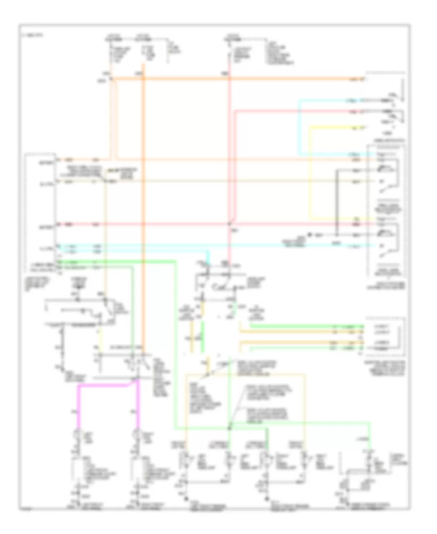
HEADLIGHTS
Headlamps/Fog Lamps Wiring Diagram, without DRL for Oldsmobile LSS 1997
List of elements for Headlamps/Fog Lamps Wiring Diagram, without DRL for Oldsmobile LSS 1997:
- c1 c1
- (body harn, 10.5 cm from instrument cluster connectors)
- (body harn, 11.5 cm from grommet at rear of left front strut)
- (left front kick panel)
- (rear corner of eng, near oil press sw)
- (right front kick panel)
- (w/ lmp monitor)
- (w/o lmp monitor)
- 15a
- 20a
- Adaptive lamp monitor control module (behind i/p, right of steering column)
- Battery
- C 1995 vftc
- C202
- C332
- C340
- El ctrl
- Exterior lights system
- Flash
- Fog lamp switch
- Fog lamps relay (position "a" in right i/p power distri- bution center)
- Fog lps ctrl
- Fog lps fuse 15a
- G100 (left front fender, near air cleaner)
- G111 (right front fender, near battery)
- G115
- G200
- G200 (left front kick panel)
- G203
- G203 (right front kick panel)
- Head
- Head lamps relay position "j"
- Headlamp dimmer switch
- Headlamp switch
- Hi beam feed
- Hi beam indi- cator
- Hi input
- Hi sens
- Hl ctrl
- Hot at all times
- I/p fuse block
- Illum
- Instru- ment cluster
- Interior lights system
- Jc c332 (right front passngr. compt., below door sill)
- Jc c340 (left front passngr. compt., below door sill)
- Lamp control module (lcm) (center of i/p)
- Lcm/hdlp circuit breaker
- Left fog lamp
- Left hi beam headlamp
- Left low beam headlamp
- Left maxi fuse block (right rear of engine compartment)
- Lo input
- Lo sens
- Nca
- Off
- On indicator
- Park
- Park lamps relay position "k"
- Park lsp/ int/lps fuse
- Red
- Red c4
- Right fog lamp
- Right hi beam headlamp
- Right i/p power distribution center
- Right low beam headlamp
- S108
- S128
- S201
- S202
- S204
- S225
- S245 (17 cm from breakout to instrument cluster connector)
- S257 (w/o lmp monitor)
- S258 (28 cm from adaptive lamp monitor, control module)
- S259 (21.5 cm from adaptive lamp monitor control module)
- S273
- S308
- Tan
- W/ adaptive lamp monitor
- W/o adaptive lamp monitor
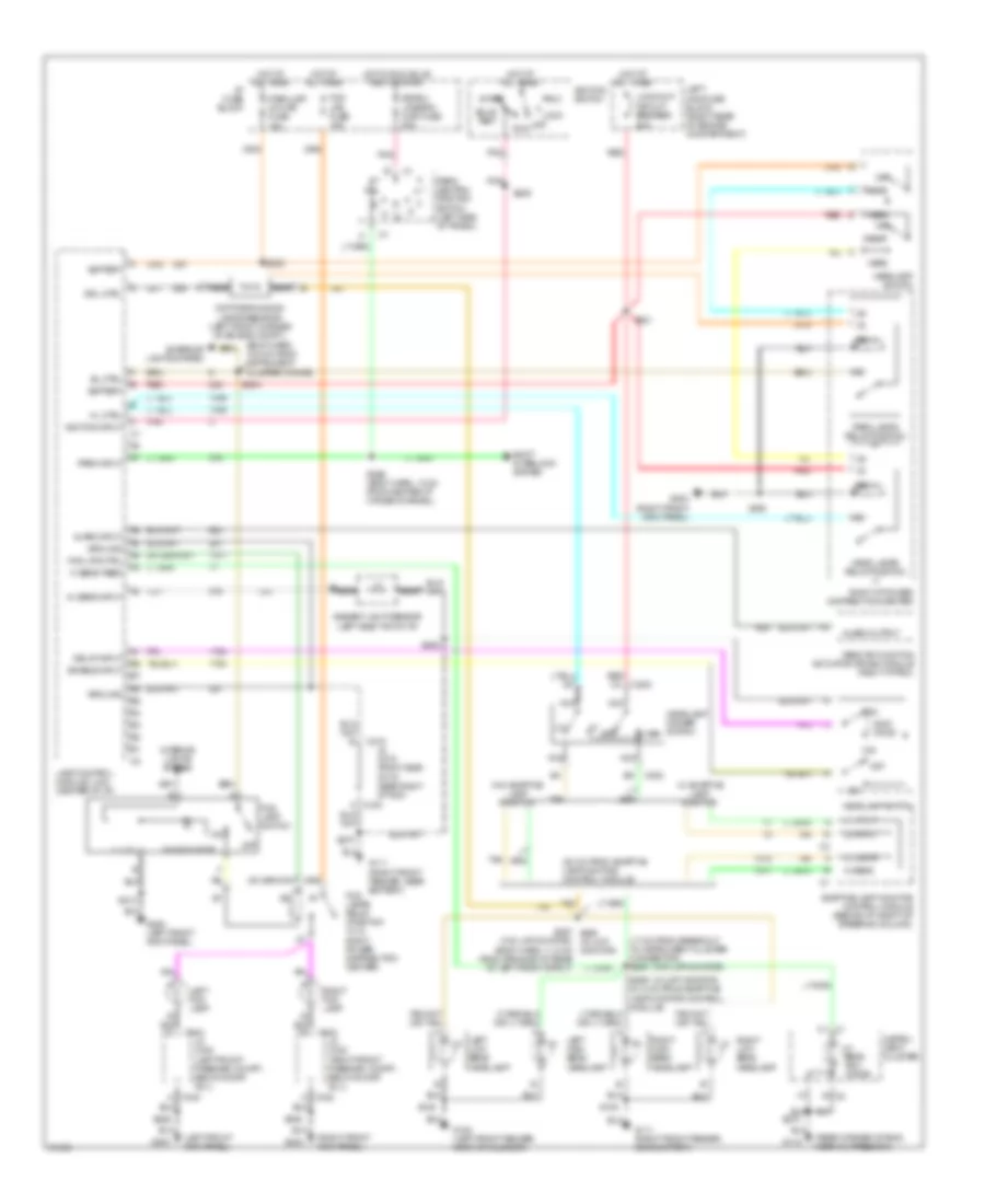
Headlight Wiring Diagram, with Twilight Sentinel/DRL for Oldsmobile LSS 1997
List of elements for Headlight Wiring Diagram, with Twilight Sentinel/DRL for Oldsmobile LSS 1997:
- alarm output
- c1 c1
- w/ adaptive lamp monitor
- (17 cm from breakout to instrument cluster connector) s245
- (28 cm from adaptive lamp monitor, control module)
- (body harn, 10.5 cm from instrument cluster conns)
- (left front kick panel)
- (rear corner of eng, near oil press sw)
- (right front kick panel)
- (w/ lmp monitor)
- (w/o lmp monitor)
- (w/o lmp monitor) (body harn, 11.5 cm from grommet at rear of left front strut)
- 15a
- 200k ohms
- 20a
- A nca
- Acc
- Adaptive lamp monitor control module (behind i/p, right of steering column)
- Al sens input
- Alarm input
- Ambient light sensor (left side top of i/p)
- Battery
- Bulb test
- C202
- C215
- C332
- C340
- Daytime running lamps resistor (left front corner of engine compt.)
- Delay input
- Drl ctrl
- El ctrl
- Enable input
- Exterior lights system
- F8 c2
- Flash
- Fog lamp switch
- Fog lamps relay (position "a" in right power distribution center)
- Fog lps ctrl
- Fog lps fuse 15a
- G100 (left front fender, near air cleaner)
- G111 (right front fender, near battery)
- G115
- G200
- G200 (left front kick panel)
- G203
- G203 (right front kick panel)
- Ground
- Head
- Head lamps relay position "j"
- Headlamp dimmer switch
- Headlamp switch
- Hi beam feed
- Hi beam indi- cator
- Hi input
- Hi sens
- Hl ctrl
- Hot at all times
- Hot in run, bulb test or start
- I/p fuse block
- Ignition input
- Ignition switch
- Illum
- Instru- ment cluster
- Interior lights system
- Jc c215 (right side of i/p, near right i/p pdc)
- Jc c332 (right front passngr. compt., below door sill)
- Jc c340 (left front passngr. compt., below door sill)
- Lamp control module (lcm) (center of i/p)
- Lcm/hdlp circuit breaker
- Left fog lamp
- Left high beam headlamp
- Left low beam headlamp
- Left maxi fuse block (right rear of engine compartment)
- Lo input
- Lo sens
- Lock
- Max
- Min
- Nca
- Off
- On indicator
- Park
- Park input
- Park lamps relay position "k"
- Park lsp/ int/lps fuse
- Park/ neutral position switch (left side of trans.)
- Pnk
- Red
- Red c4
- Remote function actuator (rfa-b) module (right i/p pdc)
- Right fog lamp
- Right high beam headlamp
- Right i/p power distribution center
- Right low beam headlamp
- Run
- S108
- S128
- S201
- S202
- S204
- S205
- S213
- S225
- S257 s258 (w/ lmp monitor)
- S259 (21.5 cm from adaptive lamp monitor control module)
- S270
- S273
- S296 (body harn, 13 cm from center i/p cross-channel)
- S308
- S908
- Shift interlock system
- Sig/bu/ lps/btsi/ cor fuse 20a
- Start
- Tan
- W/o adaptive lamp monitor
HORN
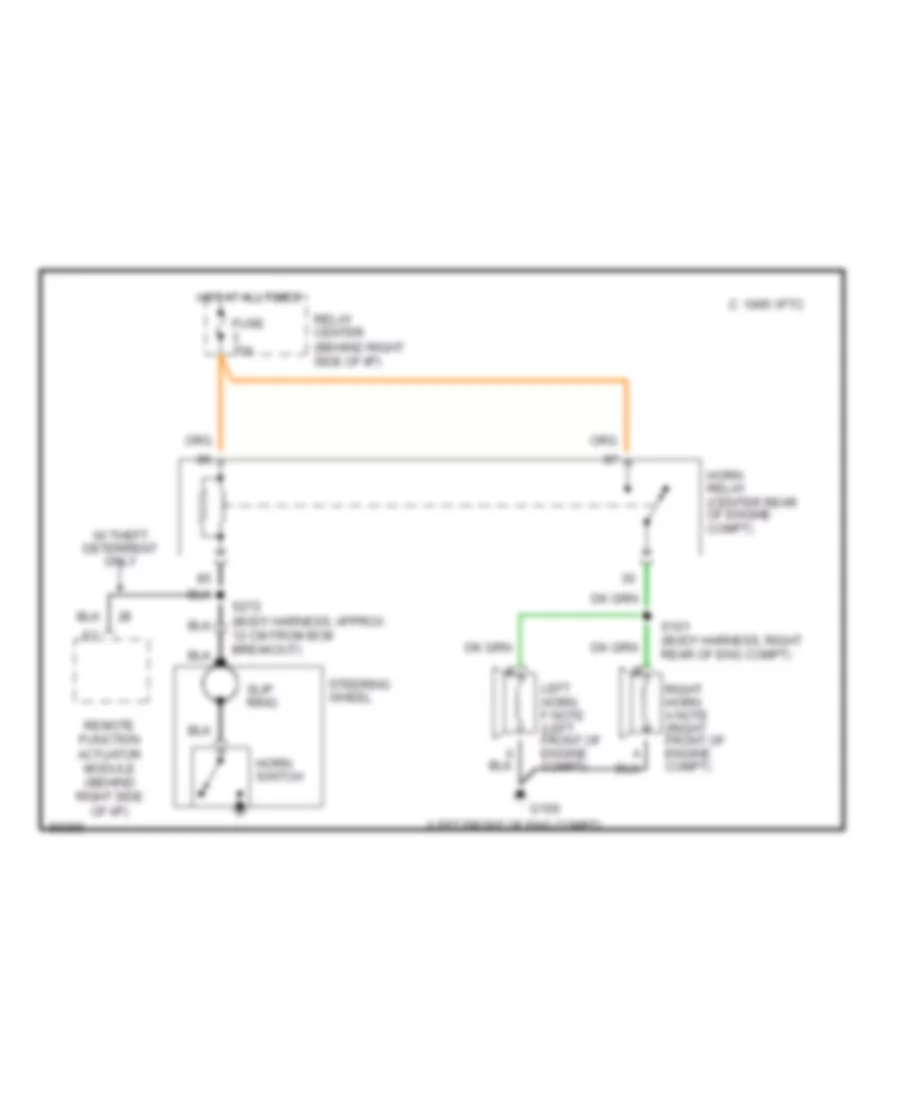
Horn Wiring Diagram for Oldsmobile LSS 1997
List of elements for Horn Wiring Diagram for Oldsmobile LSS 1997:
- (left front of eng compt)
- 1995 vftc c
- Fuse 15a
- G100
- Horn relay (center rear of engine compt)
- Horn switch
- Hot at all times
- Left horn f note (left front of engine compt)
- Relay center (behind right side of i/p)
- Remote function actuator module (behind right side of i/p)
- Right horn a note (right front of engine compt)
- S101 (body harness, right rear of eng compt)
- S272 (body harness, approx 12 cm from bcm breakout)
- Slip ring
- Steering wheel
- W/ theft deterrent only
INSTRUMENT CLUSTER
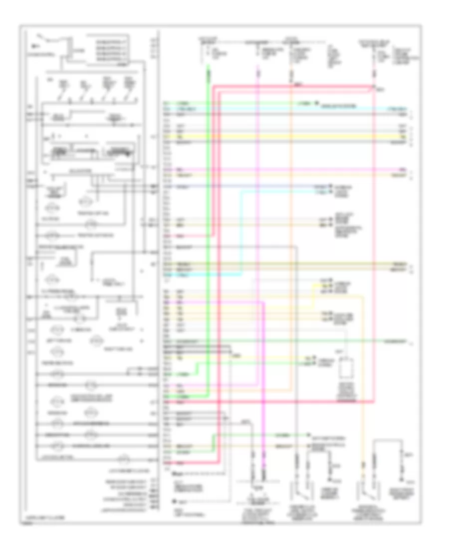
Instrument Cluster Wiring Diagram (1 of 2) for Oldsmobile LSS 1997
List of elements for Instrument Cluster Wiring Diagram (1 of 2) for Oldsmobile LSS 1997:
- (0 ohms: empty 90 ohms: full)
- (near air cleaner assembly)
- (right front fender near battery)
- (top of fuel tank)
- 16v vf
- Air bag ind.
- Airbag/vats fuse 2e 10a
- Anti-lock brakes system
- Anti-theft system
- Antilock brake ind.
- Bat
- Brake ind.
- C10
- C11
- C12
- C13
- C14
- C15
- C16
- Check oil level ind.
- Chime
- Chime control
- Chime control output
- Computer data lines system
- Coolant temp. gauge
- Crank input
- D10
- D11
- D12
- D13
- D14
- D15
- D16
- Dim level
- Dim reference
- Display input
- E/m input
- E10
- E11
- E12
- E13
- E14
- E15
- E16
- Enable prndl-a
- Enable prndl-b
- Enable prndl-c
- Enable prndl-p
- Engine controls system
- Engine coolant hot ind.
- Engine oil pressure switch (lower right rear of engine)
- Exterior lights system
- F10
- F11
- F12
- F13
- F14
- F15
- F16
- Fasten belts ind.
- Fuel gauge
- Fuel gauge sender
- Fuel tank unit
- G100
- G101
- G117 (behind power steering pump)
- G200 (left kick panel)
- Headlights system
- Hi beam ind.
- Hot at all times
- Hot in off or run
- Hot in run, bulb test or start
- Hot in start
- I/p fuse block (left side of i/p)
- Ign
- Ign fuse 3e 10a
- Ignition control module (top front of engine)
- Illumination lamps (3 bulbs)
- Instrument cluster
- Interior lights system
- Lamp monitor data input
- Left turn ind.
- Low coolant ind.
- Low oil
- Low washer fluid ind.
- Malfunction ind. lamp (service engine soon)
- Misc/rdo/ clstr fuse 9c 10a
- Nca
- Odometer
- Oil pressure ind.
- Pcm fuse 8 10a
- Pnk
- Pres. input
- Pwr
- Rear door ajar input
- Rf door ajar input
- Right i/p power distribution center
- Right turn ind.
- S128
- S207
- S225
- S233
- S270
- S273
- Security ind.
- Solid state
- Speedo- meter
- Tacho- meter
- Tan
- Test input
- Traction active ind.
- Traction off ind.
- Transient suppression
- Trip reset input
- Trip select input
- Volts ind.
- Warning system
- Washer fluid level switch (in washer fluid reservoir)
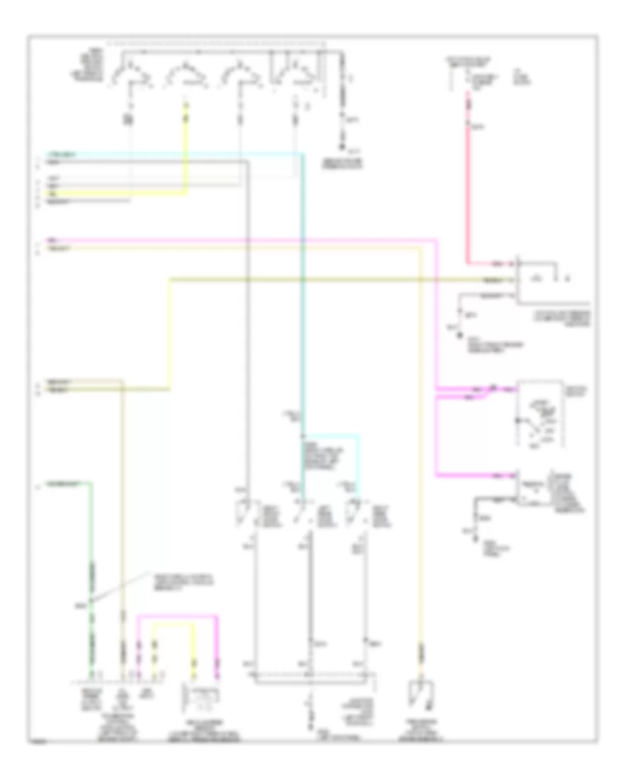
Instrument Cluster Wiring Diagram (2 of 2) for Oldsmobile LSS 1997
List of elements for Instrument Cluster Wiring Diagram (2 of 2) for Oldsmobile LSS 1997:
- (behind power steering pump)
- (body harn, 8 cm from lamp control module breakout)
- Acc
- Brake fluid level switch (master cylinder reservoir)
- Bulb test
- G101 (right front fender near battery)
- G117
- G200 (left kick panel)
- Hot in run, bulb test or start
- I/p fuse block
- Ignition switch
- Junction connector c340 (left front door sill)
- Left rear door switch
- Lock
- Low
- Low coolant sensor (lower right rear of radiator)
- Nca
- Non obd ii fuse 6e 10a
- Normal
- Off
- Oil level ind output
- Park brake switch (top of park brake assembly)
- Park/ neutral position switch (left side of transaxle)
- Pnk
- Powertrain control module (pcm) (left front of engine compt.)
- Right front door switch
- Right rear door switch
- Run
- S218
- S225
- S246
- S270
- S273
- S279
- S290 (body harn, 56 cm from top edge of left kick panel)
- S603
- Start
- Vehicle speed output 4000 p/m
- Vehicle speed sensor (lower right rear of eng, near oil pressure sensor)
- Vss input
INTERIOR LIGHTS
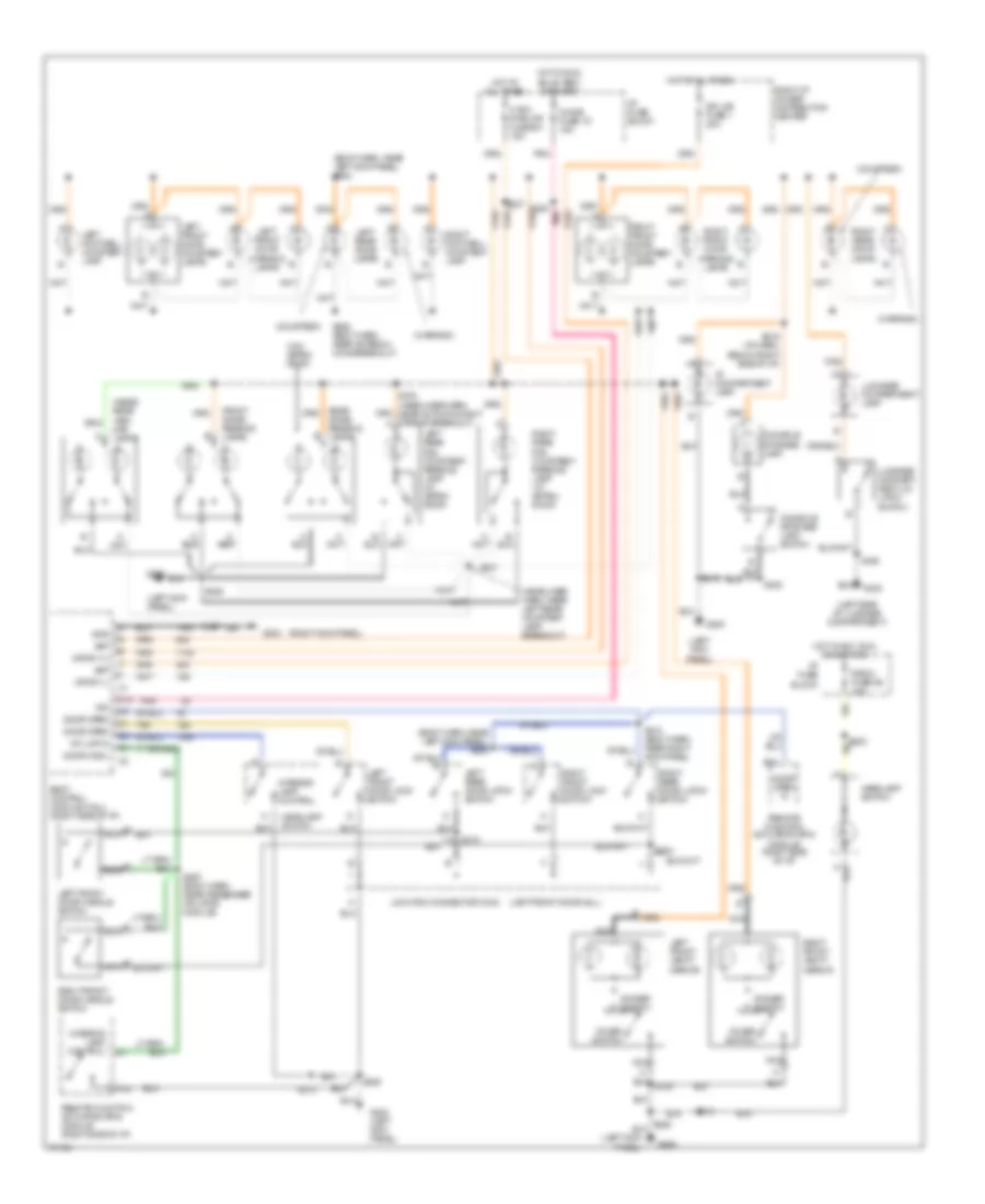
Courtesy Lamps Wiring Diagram for Oldsmobile LSS 1997
List of elements for Courtesy Lamps Wiring Diagram for Oldsmobile LSS 1997:
- (body harn, near left kick panel) s254
- (body harn, near left kick panel) s289
- (courtesy)
- (headliner harn, near left rear courtesy lamp breakout)
- (left front door sill)
- (left kick panel)
- (left side of luggage compartment)
- (right kick panel)
- (w/o astro- roof)
- (warning)
- A nca
- B nca
- Bat
- Body control module (mall) (right side of i/p)
- C13
- Chime fuse 1d 15a
- Console storage lamp
- Console storage lamp switch
- Cover switch
- Crtsy (+)
- Crtsy (-)
- Ctsy/ pwr mir fuse 6a 15a
- Dimmer switch
- Door hndl
- Door open
- Door open in
- Dr lks fuse 1 20a
- E12
- F16
- Front dome/ reading lamps
- G200
- G200 (left kick panel)
- G203
- G402
- Gnd
- Headlamp switch
- Hot at all times
- Hot in acc, run or rap (t2t)
- Hot in run, bulb test, or start
- I/p compartment lamp
- I/p fuse block
- Ign
- Inside rear view map lamps
- Int lmp in
- Interior lamp control
- Junction connector c340
- Left footwell courtesy lamp
- Left front door courtesy lamps
- Left front door handle switch
- Left front door lock switch
- Left front door warning lamps
- Left front vanity mirror
- Left rear door lamps
- Left rear door latch switch
- Left rear rail courtesy/ reading lamp (w/ astro- roof)
- Luggage compart- ment lid latch switch
- Luggage compartment lamp
- Nca
- Pnk
- Radio fuse 8d 10a
- Rear dome/ reading lamps
- Remote function actuator (rfa) module (right side of i/p)
- Right footwell courtesy lamp
- Right front door courtesy lamps
- Right front door handle switch
- Right front door lock switch
- Right front door warning lamps
- Right front vanity mirror
- Right i/p power distribution center
- Right rear door lamps
- Right rear door latch switch
- Right rear rail courtesy/ reading lamp (w/ astro- roof)
- S208
- S213
- S216 (i/p harn, below right side of i/p)
- S218
- S225
- S237
- S267 (body harn, near passenger inflator module)
- S285 (body harn, near antenna coax breakout)
- S300
- S307
- S310 (body harn, near right kick panel)
- S331
- S334 (headliner harn, near auto day/night mirror breakout)
- S338
- S400
- S603
- Tan
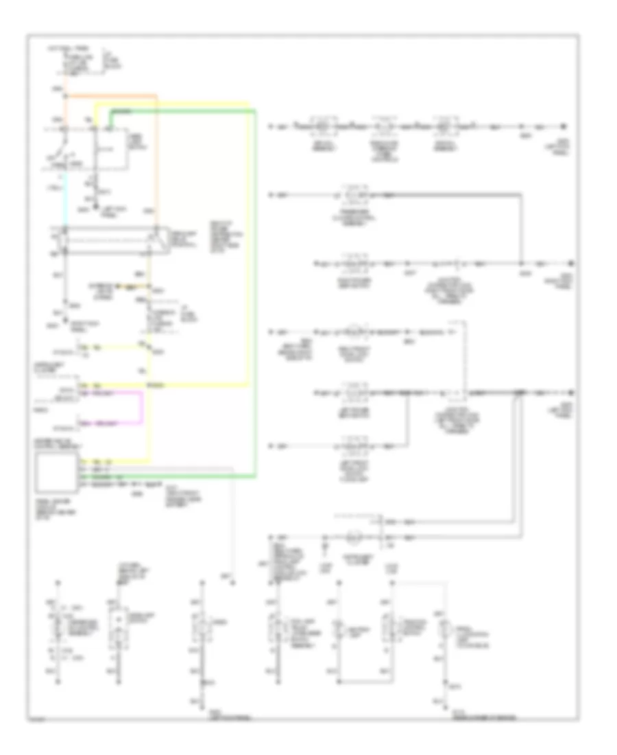
Instrument Illumination Wiring Diagram for Oldsmobile LSS 1997
List of elements for Instrument Illumination Wiring Diagram for Oldsmobile LSS 1997:
- (c61)
- (cj2)
- (i/p harn, behind left side of i/p) s291
- (left kick panel)
- (right kick panel)
- (uh8/ u2a)
- Ashtray lamp
- B nca
- D nca
- Dim in
- Dim out
- E11
- E12
- E14
- E16
- Exterior lights system
- Fog lamp/
- G101 (right front fender, near battery)
- G115 (rear corner of engine)
- G200
- G200 (left kick panel)
- G203
- G203 (right kick panel)
- Head
- Head- lamp switch
- Headlamp switch
- Heater and a/c control assembly
- Hot at all times
- I/p fuse block
- Instrument cluster
- Interior lps fuse 8d 10a
- Junction connector c332 (right front door sill, taped to harness)
- Junction connector c340 (left front door sill, taped to harness)
- Left front door lock switch floodlamp
- Left power seat switch
- Nca
- Off
- Panel dimmer module (behind center of i/p)
- Park
- Park lps/ int lps fuse 6c 15a
- Parklamp relay position l
- Passenger climate control assembly
- Prndl illumination lamp (w/ console)
- Radio
- Radio/hvac steering wheel controls
- Right front door lock switch
- Right i/p power distribution center (right side of i/p)
- Right power seat switch
- S204
- S213
- S223
- S225
- S234
- S244 (body harn, approx 2 cm from lamp control module (lcm) breakout)
- S273
- S284 (body harn, behind right side of i/p)
- S307
- S308
- S603
- S908
- Sir coil assembly
- Switch assembly
- Traction control switch
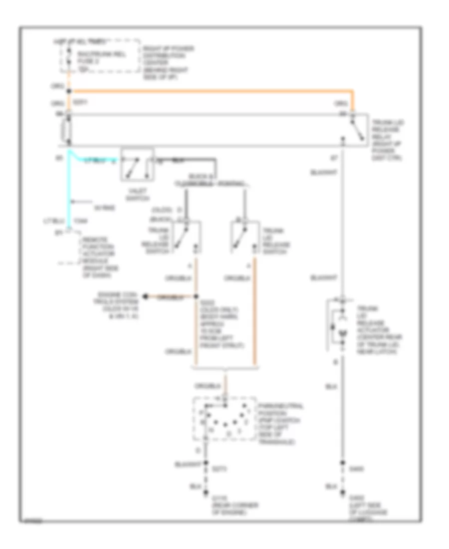
- Trunk lid release
- Vf dim in
POWER ANTENNA
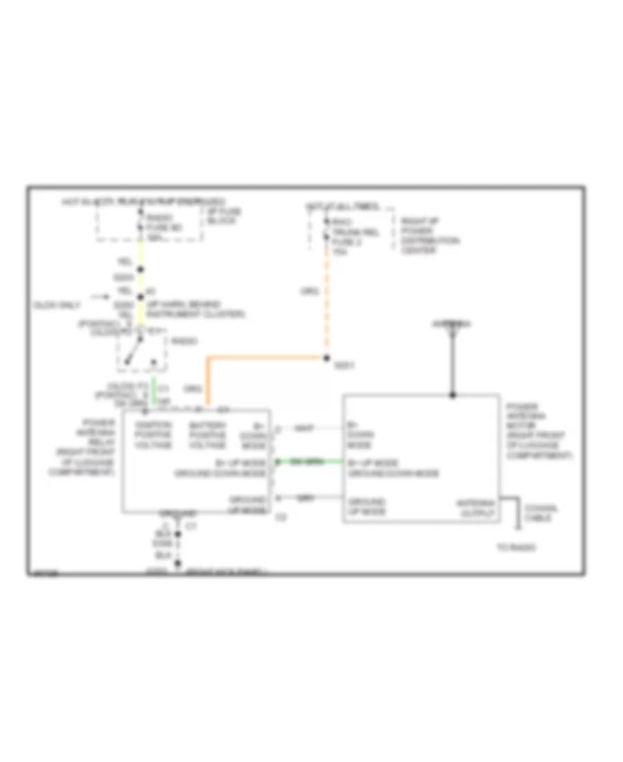
Power Antenna Wiring Diagram for Oldsmobile LSS 1997
List of elements for Power Antenna Wiring Diagram for Oldsmobile LSS 1997:
- (i/p harn, behind instrument cluster)
- (olds) (pontiac)
- (pontiac) (olds)
- (right kick panel)
- Antenna
- Antenna output
- B+ down mode
- B+ down mode
- B+ up mode ground down mode
- Battery positive voltage
- Coaxial cable
- F3 c1
- G203
- Ground
- Ground up mode
- Hot at all times
- Hot in accy, run & w/ rap energized
- I/p fuse block
- Ignition positive voltage
- Olds only
- Power antenna motor (right front of luggage compartment)
- Power antenna relay (right front of luggage compartment)
- Rac/ trunk rel fuse 2 15a
- Radio
- Radio fuse 8d 10a
- Right i/p power distribution center
- S203
- S251
- To radio
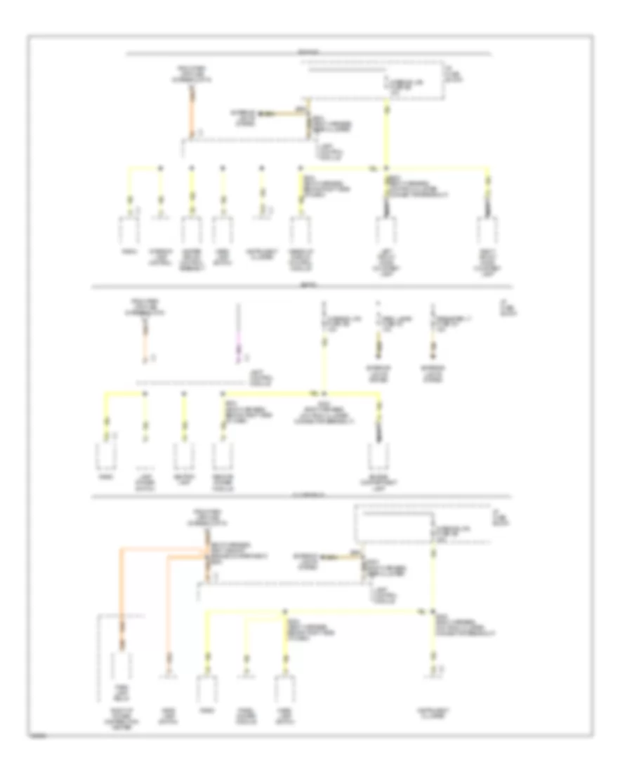
POWER DISTRIBUTION
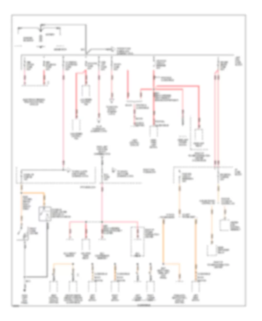
Power Distribution Wiring Diagram (1 of 6) for Oldsmobile LSS 1997
List of elements for Power Distribution Wiring Diagram (1 of 6) for Oldsmobile LSS 1997:
- (olds & pontiac) e
- (oldsmobile) d
- (pontiac) a
- Abs motor fuse 60a
- Abs solenoid fuse 40a
- Battery
- Buick
- C/ltr/rdo/ clstr/misc fuse 60a
- Cigar ltr fuse 9b 15a
- Console cigar lighter (pontiac w/ center console)
- Coolfns fuse 40a
- Elc compressor assembly
- Elc fuse 30a
- Elc height sensor
- Elc relay
- Electronic brake & traction control module
- Engine compartment)
- From left maxi-fuse block (diagram 1 of 6)
- Front cigar lighter
- Fuse 60a
- G (buick)
- G2oo (left kick panel)
- Generator
- Hdlp/lcm circuit breaker 20a
- Head/ park lamp switch
- Headlamp dimmer switch
- Headlamp relay
- Heater & a/c control assembly
- High speed control fan
- I/p fuse block
- Ign sw
- Inflator
- Lamp control module
- Left lumbar seat
- Left maxi fuse block
- Left seat switch
- Low speed control fan
- Memory seats/ memory mirrors control module (oldsmobile)
- Misc lgt fuse 60a
- Nca
- Oldsmobile
- Pneumatic seat control module (pontiac)
- Pontiac
- Pontiac & oldsmobile
- Pontiac w/ manual control a/c
- Pwr sts circuit breaker 3 25a
- Rear defogger relay
- Red
- Right i/p power distribution center
- Right i/p power distribution center (oldsmobile)
- Right lumbar seat
- Right maxi- fuse block
- Right seat switch
- Rr def/ seats fuse 60a
- Rr defog fuse 5e 30a
- S201 (body harness, right rear of red
- S213
- S227 (body harn, near left kick panel)
- S229 (i/p harn, behind right side of dash)
- S297 (body harness, near instrument cluster) red
- Seat control module (pontiac)
- Starter solenoid
- Timer relay
- To i/p fuse block (diagram 2 of 6)
- To ign sw accy fuse (diagram 2 of 6)
- To ignition switch (diagram 4 of 6)
- To rdo, clstr misc fuse 9c (diagram 4 of 6)
- To right maxi fuse block (diagram 1 of 6)
- W/ dual power seats
- W/ electronic control a/c
- W/ left power seat
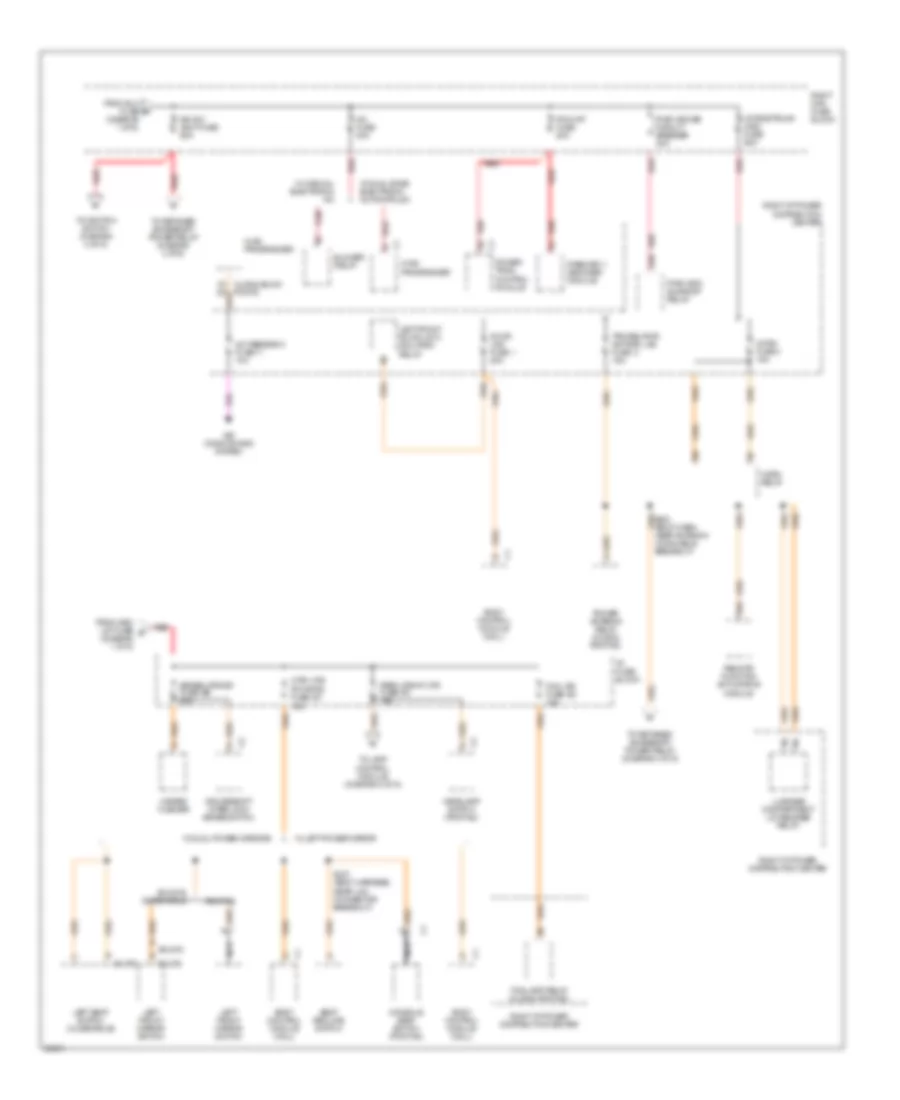
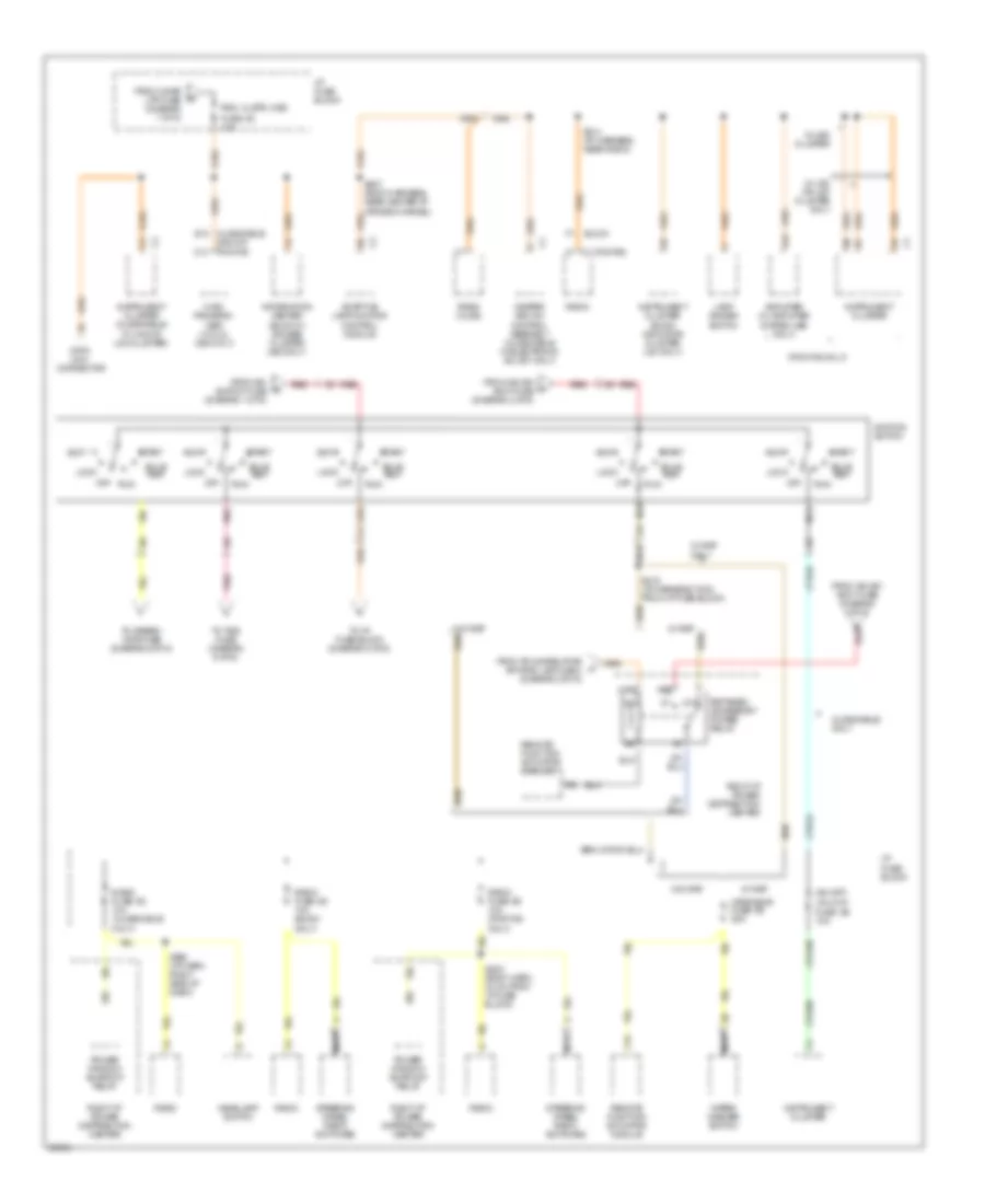
Power Distribution Wiring Diagram (2 of 6) for Oldsmobile LSS 1997
List of elements for Power Distribution Wiring Diagram (2 of 6) for Oldsmobile LSS 1997:
- (buick)
- (olds)
- A/c feedback fuse 11 10a
- A/c fuse 30a
- Air conditioning system
- Blower relay
- Body control module (mall)
- Brake lps/hzd fuse 6b 20a
- Buick & oldsmobile
- Console seat switch (pontiac)
- Cruise/shift interlock/ brake switch
- Ctsy lps/ pw mrrs fuse 6a 15a
- Door lks fuse 1 20a
- E16
- F2 olds & buick pontic
- Fog lamp relay (olds & pontiac)
- Fog lps fuse 6d 15a
- From elc fuse e (diagram 1 of 6)
- From misc lgt fuse b (diagram 1 of 6)
- H30
- Hazard flasher
- Headlamp switch (pontiac)
- Horn fuse 3 15a
- Horn relay
- Horns/trunk misc fuse 60a
- Hvac programmer
- I/p fuse block
- Ign sw accy fuse 60a
- Left front door lock isolation relay
- Left front mirror switch
- Left seat switch (oldsmobile)
- Luggage compartment lid release relay
- Nca
- Park lps/int lps fuse 6c 15a
- Pass-key ii decoder module
- Pcm/vat fuse 20a
- Pontiac
- Power antenna relay (olds & pontiac)
- Power- train control module
- Pwr wdo/ sunroof relay
- Pwr wdo/sr circuit breaker 30a
- Red
- Remote function actuator b module
- Right i/p power distribution center
- Right maxi fuse block
- S237 (body harness, near lcm connector breakout)
- S251 (body harn, near antenna coax cable breakout)
- Seat recline switch
- To ignition switch (diagram 4 of 6)
- To lamp control module (diagram 3 of 6)
- To retained accessory power relay (diagram 4 of 6)
- Trk/rel/pwr ant/rac lks fuse 2 15a
- W/ dual power mirrors
- W/ dual zone/ electronic automatic a/c
- W/ left power mirror
- W/ manual/ electronic a/c
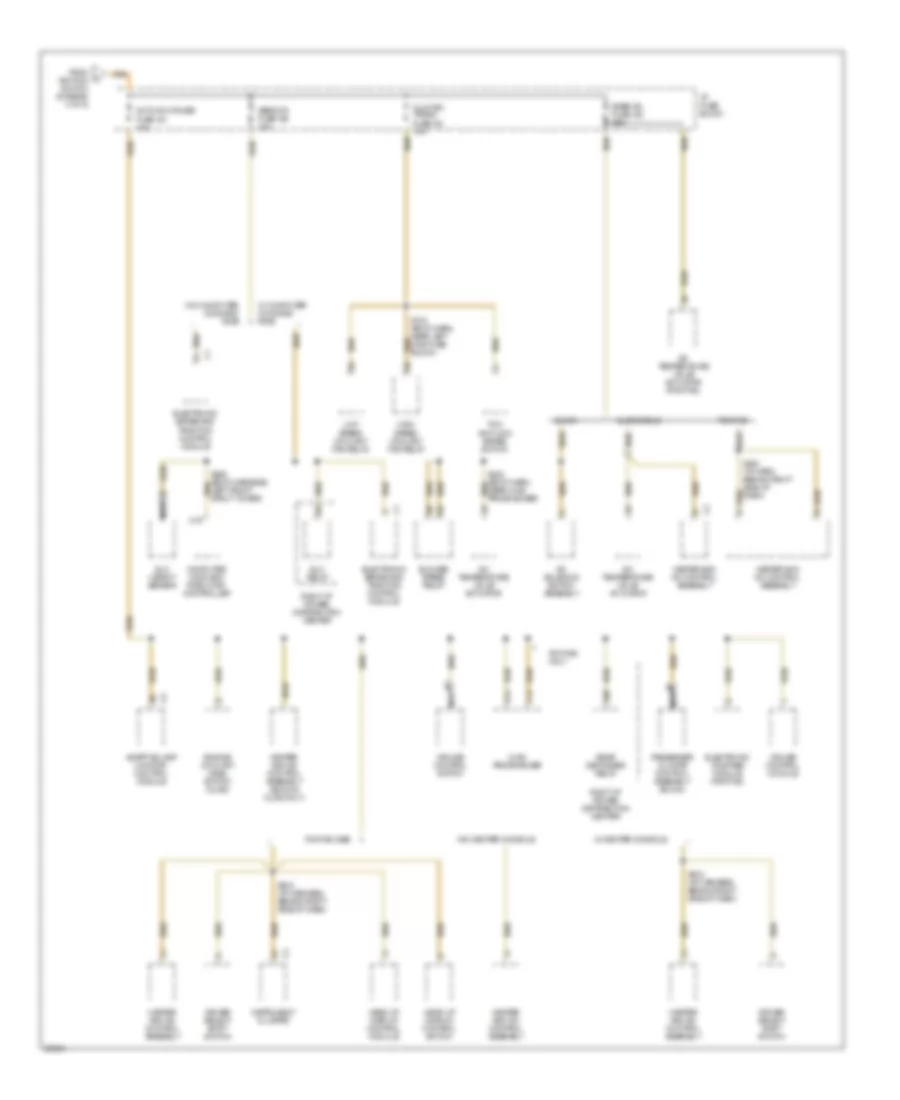
Power Distribution Wiring Diagram (3 of 6) for Oldsmobile LSS 1997
List of elements for Power Distribution Wiring Diagram (3 of 6) for Oldsmobile LSS 1997:
- Ashtray lamp
- B12
- Buick
- Engine compartment lamp
- Exterior lights system
- From park lps fuse (diagram 2 of 6)
- Head lamp switch
- Head- lamp switch
- Heads-up display control module
- Heater and a/c control assembly
- I/p fuse block
- Instrument cluster
- Interior lamp control
- Interior lps fuse 8b 10a
- K30
- Lamp control module
- Lamp dimmer switch
- Left front door courtesy lamp
- Nca
- Oldsmobile
- Panel dimmer module
- Park lamp relay
- Park lamps fuse 8c 10a
- Perimeter lt fuse 8a 15a
- Pontiac
- Radio
- Remote dimmer module
- Right front door courtesy lamp
- Right i/p power distribution center
- Right side of engine compartment) s202
- S223 (body harness, 4cm from cluster connector breakout)
- S223 (body harness, 4cm from cluster connector breakout) a
- S234 (body harness, behind right side of dash)
- Tan
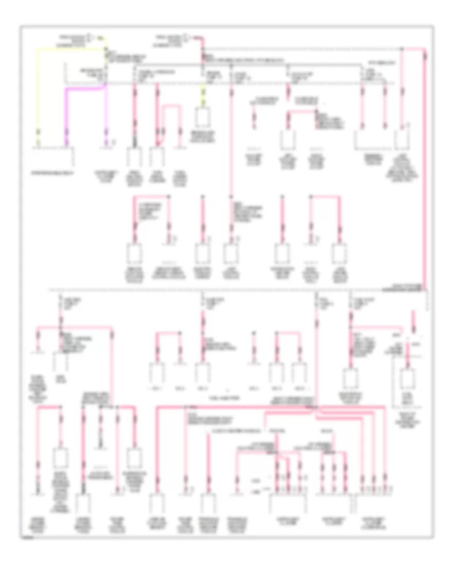
Power Distribution Wiring Diagram (4 of 6) for Oldsmobile LSS 1997
List of elements for Power Distribution Wiring Diagram (4 of 6) for Oldsmobile LSS 1997:
- (pontiac only)
- 87a
- A12
- Accy
- Adaptive lamp monitor control module
- Amplifier (w/ amplifier system ub5 only)
- Buick
- Bulb test
- C13
- Connector
- Data link
- E13
- F15
- From cigar ltr fuse (diagram 1 of 6)
- From ign sw accy fuse (diagram 2 of 6)
- From ign switch fuse (diagram 1 of 6)
- From trunk/rel/pwr ant/rac lks fuse 2 (diagram 2 of 6)
- Fuse 3e 10a
- Fuse 9c 10a
- Headlamp switch
- Heater and a/c control assembly (oldsmobile w/ electronic a/c c67 only)
- Hvac program- mer (w/ cj2, c68 only)
- I/p fuse block
- Ign off/
- Ignition switch
- Information center (buick w/ gauges cluster ub3 only)
- Instrument cluster
- Instrument cluster (buick indicator cluster u23 only)
- Instrument cluster (oldsmobile w/ uh8 or u2a cluster)
- Lamp dimmer switch
- Lock
- Nca
- Off
- Oldsmobile & buick
- Oldsmobile only
- Pnk
- Pontiac
- Power window/ sunroof relay
- Radio
- Radio (olds)
- Radio fuse 8d 10a (buick only)
- Radio fuse 8d 10a (oldsmobile only)
- Radio fuse 8d 10a (pontiac only)
- Rdo, clstr, misc
- Red
- Remote function actuator module
- Retained accessory power relay
- Right i/p power distribution center
- Run
- S203 (body harn, 43 cm from i/p fuse block)
- S207 (body harness, near center i/p cross-channel)
- S214 (i/p harness, near radio)
- S215 (i/p harness, 70cm from i/p fuse block)
- S260 (i/p harn, right side of dash)
- Start
- Steering wheel radio switches
- To airbag/ vats fuse (diagram 6 of 6)
- To i/p fuse block (diagram 5 of 6)
- To tsig fuse (diagram 6 of 6)
- Unlock
- W/ rap
- W/ rap only
- W/ u50 or u2f cluster only
- W/ ub3 cluster
- W/o rap
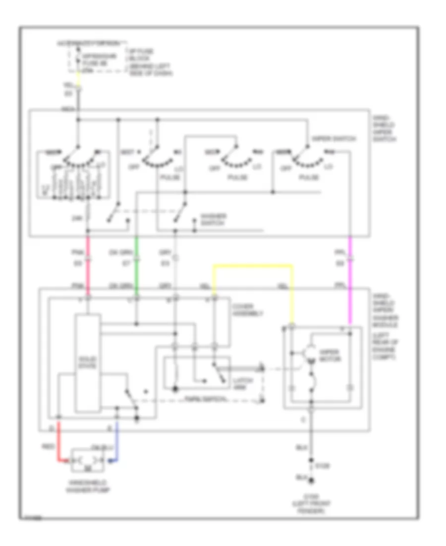
- Wiper/ washer switch
- Wpr/wshr fuse 8e 25a
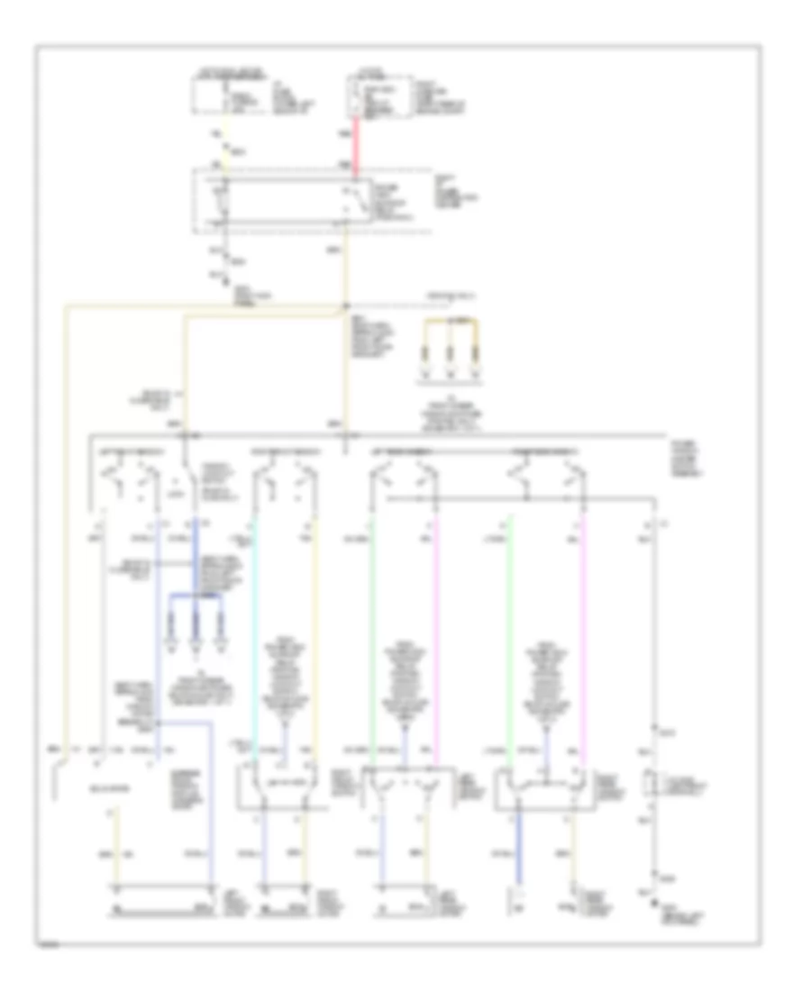
Power Distribution Wiring Diagram (5 of 6) for Oldsmobile LSS 1997
List of elements for Power Distribution Wiring Diagram (5 of 6) for Oldsmobile LSS 1997:
- A/c solenoid switch assembly
- A/c temperature valve actuator
- A/c temperature valve actuator (pontiac)
- Abs/ccr fuse 5b 10a
- Adaptive lamp monitor control module
- Auto a/c-cruise fuse 5a 10a
- Base a/c fuse 5d 25a
- Blower speed relay
- Buick
- C12
- C16
- Clg fan/ trans fuse 5c 10a
- Computer command ride (ccr) controller
- Cruise control module
- Cruise control switch
- Driver select shift switch
- E12
- Elc height sensor
- Elc relay
- Electronic brake and traction control module
- Electronic compass module (pontiac)
- Engine coolant level switch (olds)
- From ignition switch (diagram 4 of 6)
- G86
- Head up display control module
- Head up display control switch
- Heater and a/c control assembly
- Heater and a/c control assembly (buick & olds only)
- High speed coolant fan relay
- Hvac programmer
- I/p fuse block
- Instrument cluster
- Low speed coolant fan relay
- Nca
- Oldsmobile
- Passenger climate control assembly (buick)
- Pontiac
- Pontiac only
- Pontiac sse
- Rear defogger relay
- Right i/p power distribution center
- S243 (i/p harn, behind right side of dash)
- S918 (i/p harness, behind right side of dash)
- Tcc/ antilock brake switch
- W/ center console
- W/ computer command ride
- W/o center console
- W/o computer command ride
Power Distribution Wiring Diagram (6 of 6) for Oldsmobile LSS 1997
List of elements for Power Distribution Wiring Diagram (6 of 6) for Oldsmobile LSS 1997:
- (body harness, right rear of engine compt) s233
- (engine harn, right rear of engine compt) s123
- (i/p harness, 12cm from cluster) s299
- (u23)
- (ub3)
- A10
- A15
- Air bag fuse 1c 10a
- Air bag/vats fuse 2e 10a
- Automatic transmission
- Aux outlet fuse 1e 15a
- Auxiliary power outlet
- Body control module (mall)
- Buick
- C12
- C13
- Chime fuse 1d 15a
- E15
- Egr valve
- Electro- chromic mirror
- Electronic ignition (ei) module
- Evapo- rative emission canister purge vacuum switch (vin 1 (super- charged))
- Evapo- rative emission canister vent solenoid (vin k)
- Evaporative emission canister purge valve
- F16
- From ignition switch (diagram 4 of 6)
- Fuel injectors
- Fuel pump fuse 6 20a
- Fuel pump relay
- Heated oxygen sensor 1 (ho2s)
- Heated oxygen sensor 2 (ho2s)
- I/p fuse block
- Information center (buick)
- Injector fuse 7 10a
- Instrument cluster
- Instrument cluster (olds)
- Instrument cluster (oldsmobile)
- Lamp control module
- Lamp control module (w/ twilight sentinel (tb2)/ daytime running lamps (t61))
- Lamp driver module (buick)
- Left auxiliary power outlet
- Mass air flow (maf) sensor
- Memory seat/ memory mirror control module
- Misc eng fuse 5 20a
- Nca
- Near lcm connector breakout)
- No. 1
- No. 2
- No. 3
- No. 4
- No. 5
- No. 6
- Olds w/ center console
- Oldsmobile
- Oldsmobile w/ console
- Park/ neutral position switch
- Passkey ii decoder module
- Pcm fuse 8 10a
- Pnk
- Pontiac
- Power- train control module
- Remote function actuator module
- Right auxiliary power outlet
- Right i/p power distribution center
- S126 (engine harn, near injector 6)
- S130 (engine harness, right rear of engine compt)
- S205 (body harness, 63cm from i/p fuse block) pnk
- S208 (body harness, 6cm from i/p center cross- channel)
- S256 (body harness, pnk
- S271 (vin 1 only) (body harn, right rear of engine compt)
- S300 (body harn, behind right pnk
- Sensing and diagnostic module (sdm)
- Side of dash) a
- Starter enable relay
- T sig/bu lp btsi/ccr fuse 1b 20a
- Transaxle indicator decoder module
- Turn signal flasher
- Turn/ hazard switch (olds)
- Vats fuse 1a 10a
- Vin 1 (super- charged)
- Vin k
- W/ retained accessory power (kp2) only
- W/o console
POWER DOOR LOCKS
Door Lock Wiring Diagram for Oldsmobile LSS 1997
List of elements for Door Lock Wiring Diagram for Oldsmobile LSS 1997:
- (auto locks)
- (body harn, under right front seat) s302
- (part of door latch assembly)
- A tan
- Bat
- C 1995 vftc
- C13
- Ctsy/ pwr mir fuse 6a 15a
- Door lock input
- Door lock out
- Door locks fuse 1 20a
- Door unlock input
- Door unlock out
- G200 (left kick panel)
- G203 (right kick panel)
- Ground
- Hot at all times
- Hot in run, bulb test or start
- I/p fuse block
- Ign/chime clstr fuse 1d 15a
- Interior lights system
- Junction connector c332 (right front door sill)
- Junction connector c340 (left front door sill)
- Left front door lock
- Left front door lock motor
- Left rear door lock motor
- Lock
- Multi-function alarm, lock & lighting module (mall) (behind right side of dash)
- Park position input
- Park/ neutral position switch (left side of transaxle)
- Pnk
- Right front door lock motor
- Right front door lock switch
- Right i/p power distribution center (right side of dash)
- Right rear door lock motor
- S208
- S218
- S225
- S237
- S248 (body harness, 14cm from lcm connector breakout)
- S252 (body harness, 21cm from lcm connector breakout)
- S296 (body harness, 13cm from i/p cross channel)
- S303 (body harn, under right front seat)
- S307
- S308
- S603
- Sig/bu/lp btsi/ccr fuse 1b 20a
- Solid state
- Switch
- Tan
- Unlock
Keyless Entry Wiring Diagram for Oldsmobile LSS 1997
List of elements for Keyless Entry Wiring Diagram for Oldsmobile LSS 1997:
- (body harn, 32cm from top edge of left kick panel trim) s289
- (body harn, under right front seat) s302
- (body harness, 21cm from lcm connector breakout) s252
- (left front door sill)
- (part of door latch assembly)
- A tan
- Anti- theft system
- Battery (b+)
- Battery (b+) c2
- Body control module (mall) (behind right side of dash)
- C 1995 vftc
- C13
- Chime module sig
- Ctsy lp/ pwr mirror fuse 6a 15a
- Data link connector (dlc) (left side of dash)
- Delayed accy relay
- Door lock in
- Door lock out
- Door locks fuse 1 20a
- Door open in
- Door unlock in
- Door unlock out
- Dr handle switch
- Dr latch switch
- Dr lock cylinder sw
- Dr lock relay feed
- Dr lock relay out
- Dr lock switch out
- E10
- E11
- E12
- E13
- E14
- E15
- E16
- Exterior lights system
- F10
- F11
- F12
- F13
- F14
- F15
- F16
- Fuel door release solenoid (pontiac only)
- G200 (left kick panel)
- G203 (right kick panel)
- Ground
- Headlamp alarm output
- Horn relay output
- Hot at all times
- Hot in run, bulb test or start
- I/p fuse block
- Ign chime clstr fuse 1d 15a
- Ignition
- Interior lights system
- Junction connector c332 (right front a door sill)
- Junction connector c340
- Key reminder sw sig
- Left front door lock
- Left front door lock assembly
- Left front door lock motor
- Left isolation relay
- Left rear door lock assembly
- Left rear door lock motor
- Lock
- Mem seat/mirror module
- Memory systems
- Park/ neutral position switch (left side of transaxle)
- Perimeter lighting relay
- Pnk
- Pnp switch
- Rac/ trunk release fuse 2 15a
- Remote function actuator (rfa-b) module (behind right side of dash)
- Retained accessory power relay
- Right front door lock assembly
- Right front door lock motor
- Right front door lock switch
- Right i/p power distribution center (right side of dash)
- Right rear door lock assembly
- Right rear door lock motor
- Rke program enable sig
- S208
- S218
- S225
- S237
- S248 (body harn, 14cm from lcm conn breakout)
- S251
- S296 (body harn, 13cm from i/p cross- channel)
- S303 (body harn, under right front seat)
- S307
- S308
- S310 (body harn, 34cm from right kick panel ground)
- S603
- Security indicator
- Serial data signal
- Sig/bu/lp btsi/ccr fuse 1b 20a
- Solid state
- Switch
- Tamper switch signal
- Tan
- Tan tan
- Trunk release relay
- Trunk, tailgate, fuel doors system
- Unlock
- Warning systems
- Wpr/ wshr fuse 8e 25a
POWER MIRRORS
Electrochromic Mirror Wiring Diagram for Oldsmobile LSS 1997
List of elements for Electrochromic Mirror Wiring Diagram for Oldsmobile LSS 1997:
- Ambient sensor (wind- shield side)
- Automatic day-night mirror
- Automatic day/night mirror
- Buick & pont
- Chime fuse 10 15a
- Exterior lights system
- G101 (right front of engine)
- G200 (left kick panel)
- Ground
- Headlamp sensor (mirror side)
- Hot in run, bulb test or start
- I/p fuse block
- J/c c215 (behind right side of i/p)
- J/c c340 (below left front door sill)
- Left outside mirror (buick & olds w/ automatic outside mirror only)
- Max
- Min
- Mirror switch
- Nca
- Off
- Olds
- On indicator control
- Outside mirror reflectivity control
- Park/ neutral position (pnp) switch (top left side of trans)
- Pnk
- Reset to daytime high reflectivity in reverse
- S208
- S218
- S225
- S270
- S280 (body harn, behind left front strut)
- S293
- Sensitivity settings
- Sig/bu/lps/btsi/lcm fuse 18 20a
- Solid state
- Turn signal flasher
Power Mirrors Wiring Diagram for Oldsmobile LSS 1997
List of elements for Power Mirrors Wiring Diagram for Oldsmobile LSS 1997:
- Ctsy/pwr mir fuse 6a 15a
- Drive unit
- G200 (left kick panel)
- Hot at all times
- I/p fuse block
- Junc- tion conn- ector c340 (left front door sill)
- Left front outside mirror switch
- Left outside mirror
- Left- right m
- Left- right motor
- Mirror position switch
- Motor
- Nca
- Right outside mirror
- S218
- S225
- S237
- S505
- S506 (body harn, between left front door & door hinge pillar)
- Up- down m
POWER SEATS
6-Way Power Seat Wiring Diagram for Oldsmobile LSS 1997
List of elements for 6-Way Power Seat Wiring Diagram for Oldsmobile LSS 1997:
- Back
- C 1995 vftc
- Circuit breaker 3 25a
- Down
- Entire seat
- For- ward
- Forward/ back motor
- Front height
- Front height motor
- G200 (left kick panel)
- G203 (right kick panel)
- Hot at all times
- I/p fuse block
- Left front seat switch
- Left seat
- Rear height
- Rear height motor
- Right front seat switch
- Right seat
- S218
- S227
- S307
- Tan
Lumbar Wiring Diagram for Oldsmobile LSS 1997
List of elements for Lumbar Wiring Diagram for Oldsmobile LSS 1997:
- 1995 vftc c
- Circuit breaker 25a
- Deflate
- G200 (left kick pnael)
- G203 (right kick panel)
- Hot at all times
- I/p fuse block
- Inflate
- Left
- Left seat assembly
- Lumbar switch
- Nca b
- Right lumbar switch
- Right seat assembly
- S218
- S227
- S307
- Seat air pump assembly
Recliner Wiring Diagram for Oldsmobile LSS 1997
List of elements for Recliner Wiring Diagram for Oldsmobile LSS 1997:
- 1995 vftc c
- A nca
- Circuit breaker 3 25a
- G200 (left kick panel)
- G203 (right kick panel)
- Hot at all times
- I/p fuse block
- Interior lights system
- Left seat recliner motor
- Left seat switch
- Nca
- Recline down
- Recline up
- Right seat recliner motor
- Right seat switch
- S218
- S227
- S307
POWER TOP/SUNROOF
Sunroof Wiring Diagram for Oldsmobile LSS 1997
List of elements for Sunroof Wiring Diagram for Oldsmobile LSS 1997:
- Circuit breaker 1 30a
- Close
- Closed
- G203 (right kick panel)
- Ground
- Hot in run & w/ rap energized
- I/p fuse block
- Ignition
- Junction block c332 (right front door sill, on harness)
- Limit sw
- Motor ctrl
- Open
- Red
- S308
- Sunroof control module (center rear of sunroof)
- Sunroof motor assembly (center rear of sunroof)
- Sunroof switch
POWER WINDOWS
Power Window Wiring Diagram for Oldsmobile LSS 1997
List of elements for Power Window Wiring Diagram for Oldsmobile LSS 1997:
- (behind left kick panel)
- (body harn, approx 25cm from left front door grommet) s502
- (body harn, approx 4cm from window motor breakout) s500
- (buick & olds only)
- (buick & oldsmobile only)
- (pontiac only)
- Ecb
- Express down window module (driver's door)
- From power wdo/ sunroof relay (pontiac) window lock-out switch (buick & olds) (schematic 1 of 1)
- G200
- G203 (right kick panel)
- Hot at all times
- Hot in run, acc or with rap energized
- I/p fuse block (lower left side of i/p)
- J/c c340 (left front door sill)
- Left front window
- Left front window motor
- Left rear window
- Left rear window motor
- Left rear window switch
- Lock
- Power wdo/ sunroof relay (position h)
- Power window master switch assembly
- Pwr wdo/ sr circuit breaker 30a
- Radio fuse 8d 10a
- Red
- Right front window
- Right front window motor
- Right front window switch
- Right i/p power distribution center
- Right maxifuse fuse (right rear of engine compt)
- Right rear window
- Right rear window motor
- Right rear window switch
- S203
- S218
- S225
- S308
- S501
- S501 (body harn, approx 32cm from left front door grommet)
- Solid state
- Tan
- To front & rear window switches (buick & olds only) (schematic 1 of 1)
- To front & rear window switches (pontiac only) (schematic 1 of 1)
- Window lock-out switch
RADIO
Radio Wiring Diagrams for Oldsmobile LSS 1997
List of elements for Radio Wiring Diagrams for Oldsmobile LSS 1997:
- Antenna
- Antenna enable
- Battery voltage
- Coaxial cable
- Computer data lines system
- Display dimming
- E10
- E11
- E12
- E13
- E14
- E15
- E16
- F10
- F11
- F12
- F13
- F14
- F15
- F16
- G200 (left kick panel)
- Ground
- Hot at all times
- Hot in run, acc or w/ retained accessory power
- I/p fuse block (behind left side of dash, on dash panel sound insulator)
- Ign voltage
- Inflatable restraint steering wheel module coil
- Interior lights system
- Left front door speaker
- Left rear speaker
- Lf chnl out (+)
- Lf chnl out (-)
- Lr chnl out (+)
- Lr chnl out (-)
- Midrange
- Misc/ rdo/clstr fuse 9c 10a
- Nca
- Power antenna system
- Radio
- Radio fuse 8d 10a
- Rf chnl out (+)
- Rf chnl out (-)
- Right front door speaker
- Right rear speaker
- Rr chnl out (+)
- Rr chnl out (-)
- S203 (w cj2)
- S214
- Serial data uart
- Steering column fuse holder
- Steering wheel control switch
- Strg whl ctlr
- Sw1
- Sw2
- Sw3
- Sw4
- Sw5
- Sw6
- Sw7
- Sw8
- Switch fuse 2a
- Tan
- Tweeter
- Vf dimming
- W/ uw6 (6 speaker system)
- W/ ux7 (4 speaker system)
SHIFT INTERLOCKS
Shift Interlock Wiring Diagram for Oldsmobile LSS 1997
List of elements for Shift Interlock Wiring Diagram for Oldsmobile LSS 1997:
- (olds) (pontiac)
- 1995 vftc c
- C202 d3
- Cruise/shift interlock/ brake switch (brake pedal support)
- From center i/p cross channel) s230
- G200 (left kick panel)
- Hot in run, bulb test or start
- I/p fuse block
- Not used (bottom of steering column)
- Olds w/console
- Park/ neutral position switch (top left side of transaxle)
- Pnk
- Pontiac w/console
- S225
- S296 (body harn, 13 cm from center i/p cross channel)
- S300 s206
- Shift interlock solenoid (bottom of steering column)
- Shift interlock solenoid (on console gear shifter)
- Sig/bu lps/ btsi/lcm fuse 18 20a
- W/o console
STARTING/CHARGING
Charging Wiring Diagram for Oldsmobile LSS 1997
List of elements for Charging Wiring Diagram for Oldsmobile LSS 1997:
- (1997)
- (1998)
- (body harness, approx 31 cm from dlc)
- (buick)
- (center front of engine)
- (near battery)
- (not used)
- (pontiac u2f, buick u23)
- (pontiac)
- (u50) (ub3)
- B1 (buick)
- B13
- B13 a13
- Bat
- Battery
- Buick ub3
- Chime fuse 1d 15a
- Control
- Data link connector (under left side of dash)
- F16
- G111
- G125
- Gen. term. f input
- Gen. term. l output
- Generator l
- Hot in run, bulb test or start
- I/p fuse block
- I/p junction block (behind right side of dash)
- Instrument cluster
- Low voltage input
- Olds (uh8)
- Others
- Pcm fuse 8 10a
- Pnk
- Pontiac (u2f) buick (u23)
- Power distribution system
- Powertrain control module (left front corner of engine compatrment)
- Red
- Remote indicator bank (buick ub3)
- S208
- S226
- S233
- S299
- Serial data
- Serial data line
- Starting circuit
- Tan
- Ub3, u50 (pontiac)
- Volts ind.
- Volts indicator control
Starting Wiring Diagram for Oldsmobile LSS 1997
List of elements for Starting Wiring Diagram for Oldsmobile LSS 1997:
- (center front of engine)
- (near battery)
- Accy
- Airbag/ vats fuse 2e 10a
- Battery
- Bulb test
- Charging circuit
- D5 nca
- G111
- G125
- Hold- in coil
- I/p fuse block (behind left side of dash)
- Ign sw fuse 60a
- Ignition switch
- Instrument cluster system (olds)
- Left maxi fuse block
- Lock
- Nca b6
- Off
- Park/neutral position (pnp) switch (on left side of transaxle)
- Pass key theft deterrent module (near rear of glove box)
- Power distribution system
- Pull- in coil
- Red
- Right hand maxi fuse block
- Run
- Start
- Starter enable
- Starter enable relay (behind dash, left of steering column)
- Starter motor
- Starter solenoid
SUPPLEMENTAL RESTRAINTS
Supplemental Restraint Wiring Diagram for Oldsmobile LSS 1997
List of elements for Supplemental Restraint Wiring Diagram for Oldsmobile LSS 1997:
- (body harn, right rear of engine compt)
- Air bag fuse 10a
- Air bag warning indicator
- B nca
- Bar
- Body control module (behind right side of i/p)
- Data line
- Data link connector (right of steering column)
- Driver high
- Driver inflator module (center of steering whl)
- Driver low
- F16
- Front end discriminating sensor (center front of engine compt)
- G200 (left kick panel)
- G301 (below right front seat)
- Ground
- Hot in run, bulb test or start
- I/p fuse block
- Ign 1
- Indicator lamp
- Instrument cluster
- Nca
- Passenger high
- Passenger inflator module (right i/p)
- Passenger low
- Pcm fuse 10a
- Pnk
- S225 (body harn, near left kick panel)
- S226 (body harn, near dlc)
- S233
- S309 (body harn, near ground g203 at right kick panel)
- Seat belt sig
- Seat belt switch
- Sensing and diagnostic module (below right front seat)
- Sensor feed
- Shorting
- Sir coil assembly
- Tan
TRANSMISSION
3.8L
3.8L (VIN 1), Transmission Wiring Diagram, 4T65-E for Oldsmobile LSS 1997
List of elements for 3.8L (VIN 1), Transmission Wiring Diagram, 4T65-E for Oldsmobile LSS 1997:
- (body harn, approx 4.5 cm lcm in center of dash) s239
- (body harness, 27 cm from lcm conn breakout at center of dash)
- (partial) (engine harness, 32 cm from 66-pin conn near a/c accumulator)
- (top left side of transaxle) park/neutral position switch
- (under left side of dash) data link connector (partial)
- 1-2 shift sol
- 2-3 shift sol
- 5v reference
- A/t iss sens hi in
- At iss sens lo in
- Auto a/c/ cruise fuse no 5a (i/p fuse block)
- Automatic transaxle (4t65-e)
- Automatic transaxle fluid pressure manual valve position switch
- Automatic transaxle fluid temperature sensor
- Automatic transaxle input shaft speed sensor
- Battery in
- Brake switch assembly (behind left side of dash)
- Brake switch in
- Buick/pontiac
- Clg fan fuse 5c 10a
- Cooling fan relays
- Cruise control system
- Data class ii
- Ect sensor in
- Egr valve
- Engine coolant temperature sensor (rear of engine below thermostat housing)
- G120 (right side of engine, near oil pressure switch)
- G200 (left kick panel)
- Heated oxygen sensors
- Hot at all times
- Hot in run
- Hot in run, bulb test or start
- I/p fuse block
- Ignition in
- Instrument cluster
- Instrument cluster & transmission decoder module
- Instrument cluster system
- Malfunction indicator lamp
- Mass air flow meter
- Mil indic ctrl
- Misc eng fuse 5 20a
- Nca
- Norm
- Oldsmobile
- Passkey decoder module
- Pc sol hi ctrl
- Pc sol low
- Pcm fuse 8 10a
- Pcm ground
- Pcm/vats fuse 4 20a
- Perform
- Pnk
- Powertrain control module (left front corner of emgine compt in air cleaner assembly)
- Pressure control sol
- Red
- Right i/p power distribution center
- Right maxi- fuse block
- S104
- S110
- S121
- S122 (partial) (eng harn, approx 10 cm from iat sensor)
- S123
- S130
- S206
- S226 (partial) (body harness, 32cm from data link connector)
- S233
- S256
- S278 (partial) (body harness, 43 cm from rfa module breakout)
- S299
- S929 (partial)
- Sensor return
- Serial data
- Shift sel in
- Shift select switch (pontiac w/ fw1)
- Tan
- Tcc pwm sol
- Tcc rel
- Tcc release sw
- Tcc/ anti-lock switch
- Tft sensor in
- Throttle position sensor
- Tp sensor in
- Tr sw a in
- Tr sw b in
- Tr sw c in
- Tr sw p in
- Tr-a
- Tr-b
- Tr-c
- Trans range-a
- Trans range-b
- Trans range-c
- Vehicle speed sensor (right side of engine compt on transaxle)
- Vss hi in
- Vss lo in
3.8L (VIN K), Transmission Wiring Diagram, 4T60-E for Oldsmobile LSS 1997
List of elements for 3.8L (VIN K), Transmission Wiring Diagram, 4T60-E for Oldsmobile LSS 1997:
- (body harn, approx 4.5 cm lcm in center of dash) s239
- (buick w/ ub3 cluster)
- (buick-pontiac only)
- (buick-pontiac)
- (exc buick w/ ub3)
- (partial) (engine harness, 32 cm from 66-pin conn near a/c accumulator)
- (top left side of transaxle) park/neutral position switch
- (under left side of dash) data link connector (partial)
- 1-2 shift sol
- 2-3 shift sol
- 5v reference
- Automatic transaxle (4t60-e)
- Battery in
- Brake switch assembly (behind left side of dash)
- Brake switch in
- Buick & pontiac
- Buick w/ ub3
- Chime fuse 1d 15a
- Clg fan fuse 5c 10a
- Computer data lines system
- Cooling fan relays
- Cruise control system
- Data class ii
- Ect sensor in
- Egr valve, pcm, o2 sensors, evap valves
- Engine coolant temperature sensor (rear of engine below thermostat housing)
- Exc buick w/ ub3
- G120 (right side of engine, near oil pressure switch)
- Hot at all times
- Hot in run
- Hot in run, bulb test or start
- I/p fuse block
- Ignition in
- Instrument cluster & transmission decoder module
- Instrument cluster (oldsmobile)
- Instrument cluster or information center
- Malfunction indicator lamp
- Mass air flow meter
- Mil indic ctrl
- Misc eng fuse 5 20a
- Oldsmobile
- Passkey theft deterrent module
- Pcm fuse 8 10a
- Pcm ground
- Pcm/vats fuse 4 20a
- Pnk
- Powertrain control module (left front corner of emgine compt in air cleaner assembly)
- Prndl-a
- Prndl-c
- Prndl-d
- Red
- Right i/p power distribution center
- Right maxifuse block
- S104
- S110
- S121
- S122 (partial) (engine harness, 47 cm from 66-pin conn near a/c accumulator)
- S123
- S130
- S208
- S226 (partial) (body harness, 32 cm from data link connector)
- S233
- S278 (partial) (body harness, 43 cm from rfa module breakout)
- S299
- Sensor return
- Serial data
- Tan
- Tcc pwm sol
- Tcc sol
- Tcc/ anti-lock switch
- Tft sensor
- Tft sensor in
- Throttle position sensor (throttle body)
- Tp sensor in
- Trans range-a
- Trans range-b
- Trans range-c
- Trans range-p
- Uart data
- Vehicle speed sensor (right side of engine compt on transaxle)
- Vss hi in
- Vss lo in
TRUNK, TAILGATE, FUEL DOOR
Trunk Release Wiring Diagram for Oldsmobile LSS 1997
List of elements for Trunk Release Wiring Diagram for Oldsmobile LSS 1997:
- (buick)
- (olds)
- Buick & oldsmobile
- Engine con- trols system (olds w/ v6 & vin 1, k)
- G115 (rear corner of engine)
- G402 (left side of luggage compt)
- Hot at all times
- Park/neutral position (pnp) switch (top left side of transaxle)
- Pontiac
- Rac/trunk rel fuse 2 15a
- Remote function actuator module (right side of dash)
- Right i/p power distribution center (behind right side of i/p)
- S222 (olds only) (body harn, approx 15.5cm from left front strut)
- S251
- S273
- S400
- Trunk lid release actuator (center rear of trunk lid, near latch)
- Trunk lid release relay (right i/p power dist ctr)
- Trunk lid release switch
- Valet switch
- W/ rke
WARNING SYSTEMS
Warning System Wiring Diagrams for Oldsmobile LSS 1997
List of elements for Warning System Wiring Diagrams for Oldsmobile LSS 1997:
- (body harn, approx 31.5 cm from top left kick panel)
- (body harn, near right kick panel) s309
- (buick)
- (left kick panel)
- (olds)
- (pont ex ub3)
- (pont ub3)
- 1845 (or 33)
- 80 (or 653)
- A12
- A13
- All others
- B11
- Battery (b+)
- Battery (b+)
- Body control module (mall) (behind right side of i/p, on multi-use bracket)
- Brake ind
- Bu- ick
- Buick & pont only
- Buick w/ ub3 cluster option only
- C12
- C13
- C15
- C202
- Chime control or brake ind
- Chime fuse 1d 15a
- Chime in or brake warning in
- Ctsy/pwr mir fuse 6a 15a
- D12
- Door open in
- Dr lks fuse 1 20a
- E12
- E13
- E16
- Engine controls system
- Exterior lights system
- Exterior lights system (buick: lamp control module; ex buick: headlamp switch)
- Fasten belts ind
- Fasten belts ind ctrl
- G200
- G200 (left kick panel)
- G203 (right kick panel)
- Ground
- Hot at all times
- Hot in run or start
- Hot in run, bulb test or start
- I/p fuse block
- Ignition key warning switch (inside steering column assembly)
- Ignition power
- Information center
- Instrument cluster
- Instrument cluster system
- Junction connector c332 (right front door sill)
- Junction connector c340 (left front door sill)
- Key in ignition in
- Key in input
- Key in output
- Lamps on in
- Left front door latch switch c1
- Left front seat belt switch
- Left frt door open in
- Left rear door latch switch c1
- Nca
- Olds
- Open door input
- Pnk
- Pont
- Power distrib- ution system
- Power distribution system
- Powertrain control module (pcm) (left front of engine compt)
- Remote function actuator (rfa) module (behind right side of i/p, near right i/p power distribution center)
- Right front door latch switch c1
- Right i/p power distribution center
- Right rear door latch switch c1
- S200 (i/p harn, approx 13 cm from instrument cluster breakout)
- S208
- S218
- S220 (body harn, behind left front strut)
- S225
- S237
- S246 (body harn, approx 8 cm from lamp control module breakout)
- S289
- S307
- S308
- S310 (body harn, near right kick panel)
- S603
- Seat belt sw in
- T/sig/bu lps/btsi/lcm fuse 1b 20a
- Tan
- Turn flasher (below left side of i/p)
- Turn signal in
- Vss in
- Vss output
- W/ remote keyless entry
- W/o remote keyless entry
WIPER/WASHER
Wiper/Washer Wiring Diagram for Oldsmobile LSS 1997
List of elements for Wiper/Washer Wiring Diagram for Oldsmobile LSS 1997:
- (left rear of engine compt)
- 1.2 m
- 24k
- Cover assembly
- G100 (left front fender)
- Hot in accy or run
- I/p fuse block (behind left side of dash)
- Latch arm
- Mist
- Nca
- Off
- Park switch
- Pnk
- Pulse
- Red
- S128
- Solid state
- Washer switch
- Wind- shield wiper switch
- Wind- shield wiper/ washer module
- Windshield washer pump
- Wiper motor
- Wiper switch
- Wpr/wshr fuse 8e 25a