AIR CONDITIONING
Compressor Wiring Diagram for Oldsmobile Silhouette GL 2001

List of elements for Compressor Wiring Diagram for Oldsmobile Silhouette GL 2001:
- (left rear of engine) g114
- +5v reference
- A/c clu diode
- A/c clu fuse 10a
- A/c clu relay
- A/c compressor clutch
- A/c press signal
- A/c refrigerent pressure sensor (left side of engine compt, on accumulator)
- A/c request
- C11
- Clutch request
- Comp control
- Engine controls system
- Fuse block (right side of dash)
- G201 (right side of dash)
- Ground
- Hot at all times
- Hot in run
- Hvac control module
- Hvac fuse 10a
- Ignition
- Low reference
- Powertrain control module (left front side of engine compt, in air cleaner assembly)
- S105 (engine harn, 20 cm from coolant fan breakout)
- S167 (engine harn, 5 cm from pcm breakout)
- S213 (dash harn, 72 cm from cigar lighter)
- Underhood fuse block (right front of engine compt)
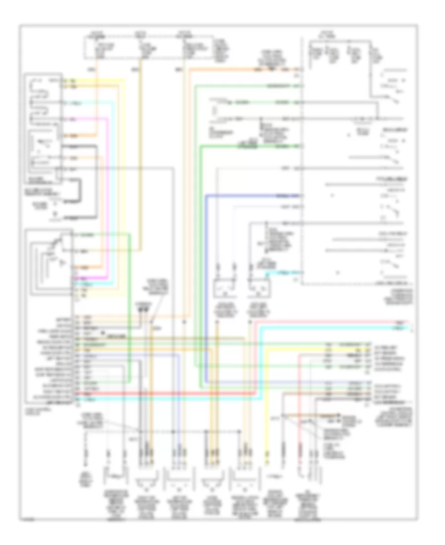
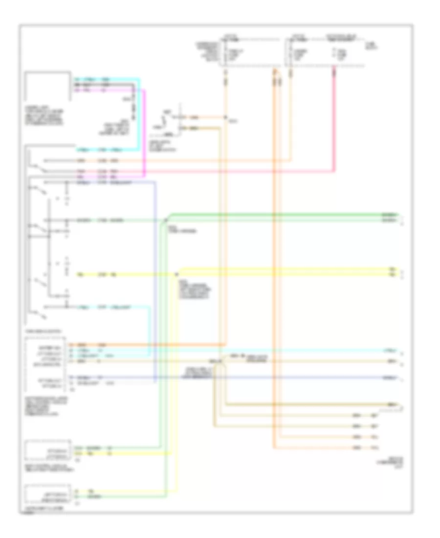
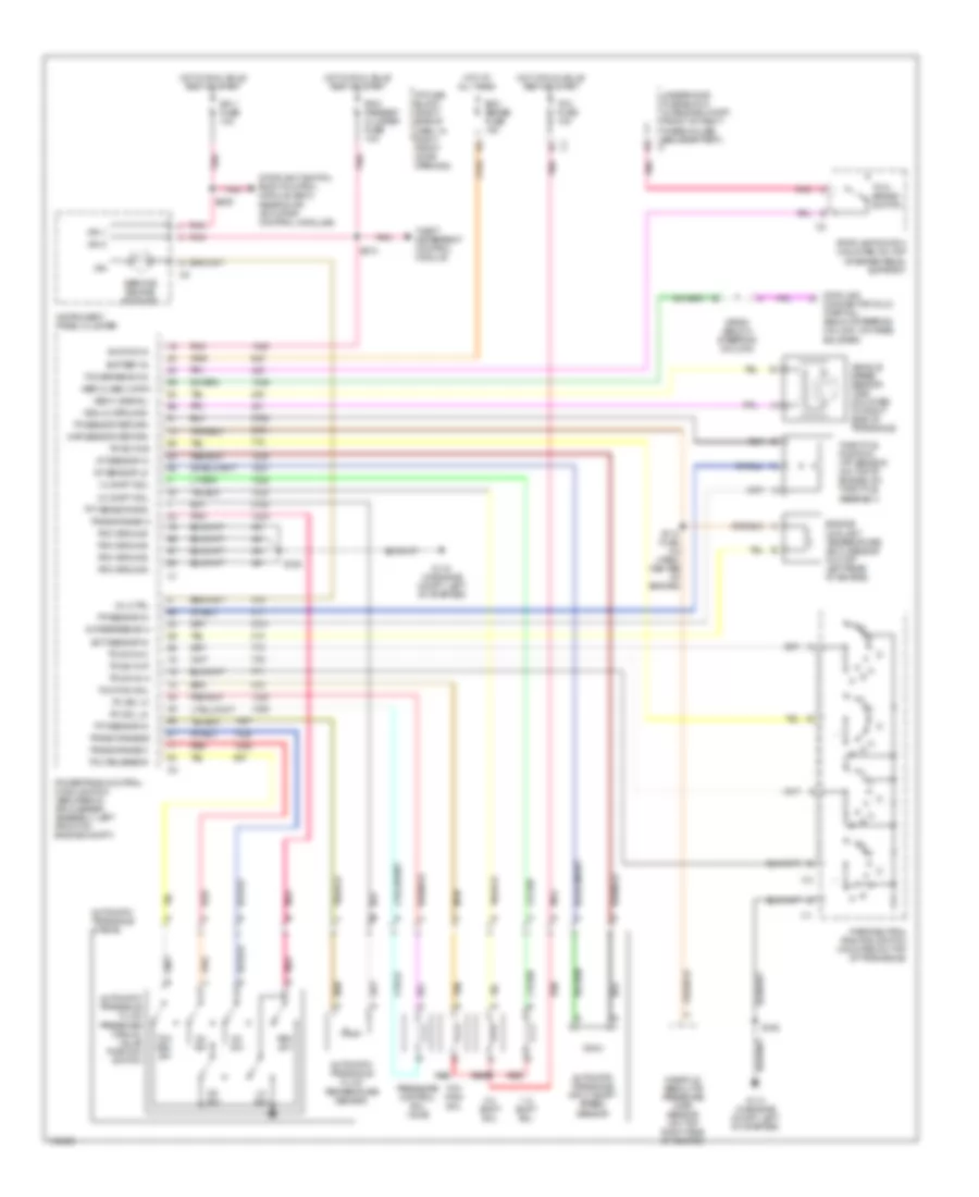
Manual A/C Wiring Diagram (1 of 2) for Oldsmobile Silhouette GL 2001
List of elements for Manual A/C Wiring Diagram (1 of 2) for Oldsmobile Silhouette GL 2001:
- (dash harn, 15 cm from multi-function sw breakout) s202
- (dash harn, 16 cm from relay center breakout)
- (dash harn, 72 cm from cigar lighter breakout)
- (engine harn, 5 cm from pcm breakout)
- (fuel inj harn, center of the engine)
- +5v reference
- A/c compressor clutch
- A/c clu diode
- A/c clu fuse 30a
- A/c clu relay
- A/c press signal
- A/c refrigerent pressure sensor (left side
- A/c request
- A/c request sig
- A10
- Aux mode door ctrl
- Battery
- Blower motor
- Blower motor relay
- Blower motor resistor assembly
- Blower sw off
- C10
- C11
- Comp control
- Cool fan 1 fuse 30a
- Cool fan 2 fuse 30a
- Cool fan 1 relay
- Cool fan 2 relay
- Cool fan relay
- Coolant fan 1
- Coolant fan 2
- Cooling fan (left) (mounted to radiator)
- Cooling fan (right) (mounted to radiator)
- Defogger
- Drl/hvac/ temp/htd st fuse 10a
- Ect sensor
- Engine controls system
- Engine coolant temperature (ect) sensor (top left rear of engine)
- Evap temp sens +5v
- Evap temp sens rtn
- Evaporative temperature sensor (behind center of dash, on hvac assembly)
- F11
- Frt hvac hi blwr c.b. 30a
- Fuse block (behind right side of dash)
- G114 (left rear of engine)
- G201 (right side of dash)
- Ground
- Hot at all times
- Hot in run
- Hvac blower fuse 25a
- Hvac control module
- Ignition
- Interior lights
- Lamp dim sig
- Left air temperature actuator (left side of hvac module)
- Left temp act
- Low reference
- Mode actuator (left side of hvac module)
- Mode door ctrl
- Nca
- Of engine compt, on accumulator)
- Off
- Park lamps on sig
- Powertrain control module (left front side of engine compt, in air cleaner assembly)
- Radio fuse 10a
- Rear defog
- Recirc door ctrl
- Recirculation actuator (behind right side of dash, above blower motor)
- Red
- Right air temperature actuator (left side of hvac module)
- Right temp act
- S105 (engine harn, 20 cm from coolant fan breakout)
- S105 (engine harn, 4 cm from engine fan wiring harn breakout)
- S110
- S167
- S213
- S264
- Tan
- Underhood fuse block (right front of engine compt)
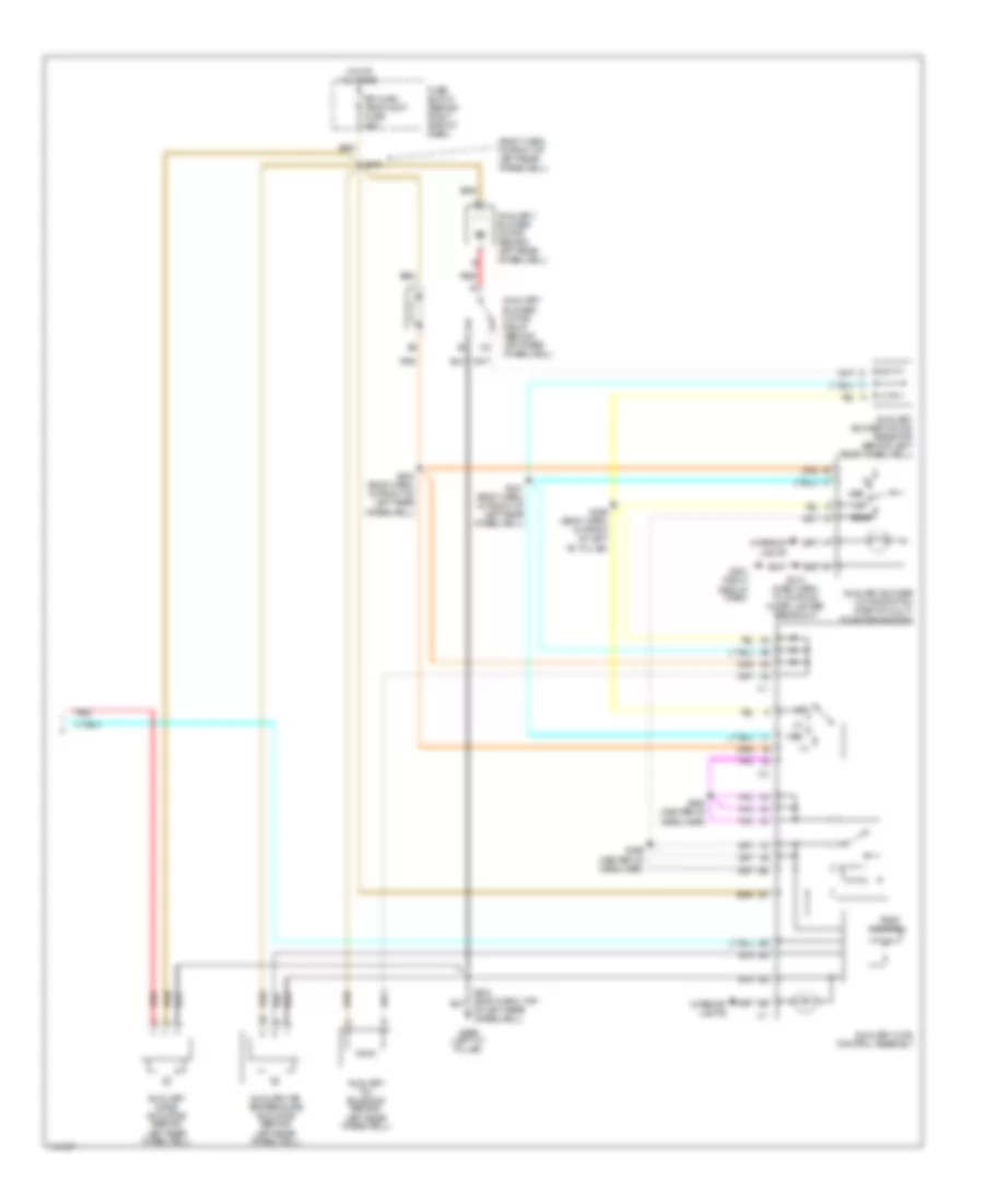
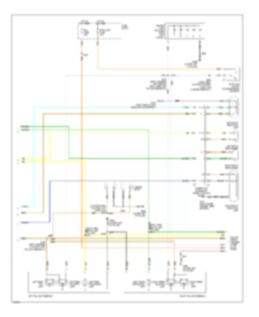
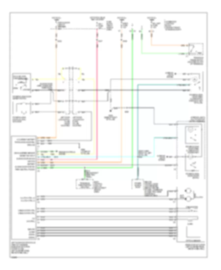
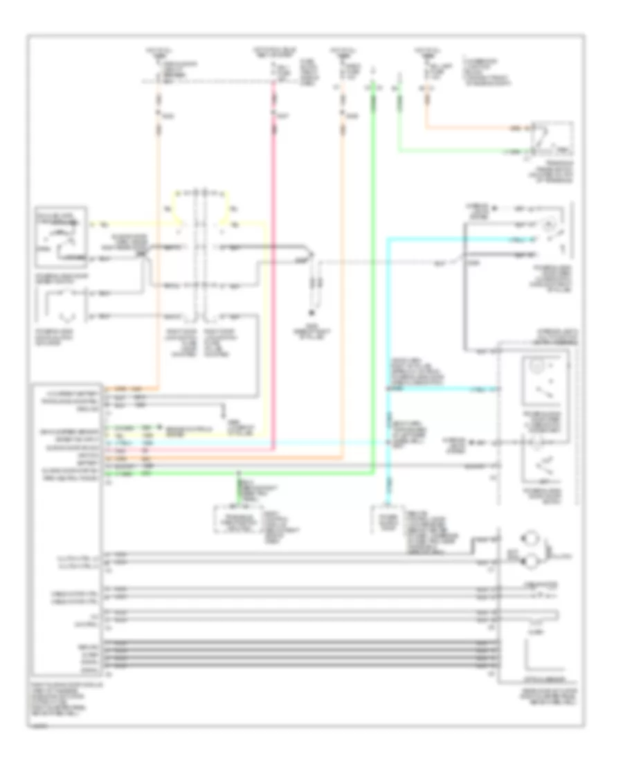
Manual A/C Wiring Diagram (2 of 2) for Oldsmobile Silhouette GL 2001
List of elements for Manual A/C Wiring Diagram (2 of 2) for Oldsmobile Silhouette GL 2001:
- (body harn, in front of left rear wheelwell)
- Auxiliary air temperature actuator (behind left rear wheelwell)
- Auxiliary blower motor (behind left rear wheelwell)
- Auxiliary blower motor relay (behind left rear wheelwell)
- Auxiliary blower motor resistor (behind left rear wheelwell)
- Auxiliary blower motor switch (part of multi- function switch)
- Auxiliary hvac control assembly
- Auxiliary mode actuator (behind left rear wheelwell)
- Auxiliary txv solenoid (behind
- Fuse block (behind right side of dash)
- G201 (right side of dash)
- G999 (left "d" pillar)
- Hot at all times
- Interior lights
- Left rear wheelwell)
- Med
- Of left rear wheelwell)
- Off
- Rear
- Red
- Rr hvac/ temp cont fuse 25a
- S213 (dash harn, 72 cm from cigar lighter breakout)
- S341 (body harn, in front of left rear wheelwell)
- S343 (body harn, in front of left rear wheelwell)
- S345
- S394 (center of headliner)
- S396 (center of headliner)
- S399 (body harn, in front of left "b" pillar)
- Temp control
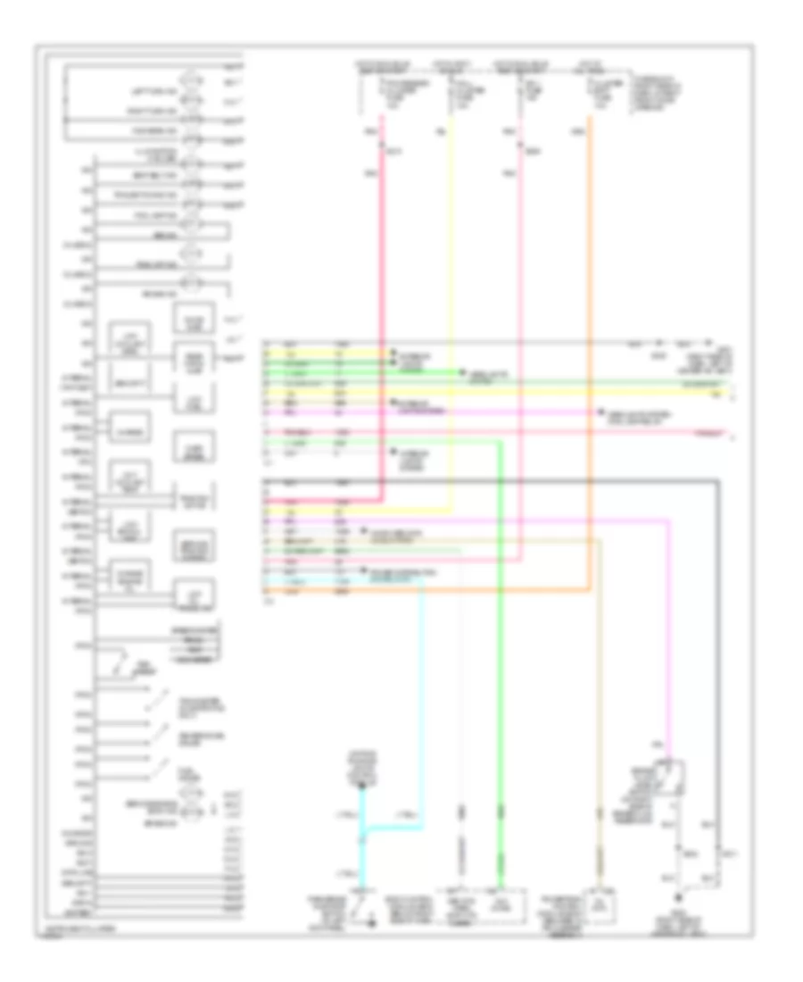
ANTI-LOCK BRAKES
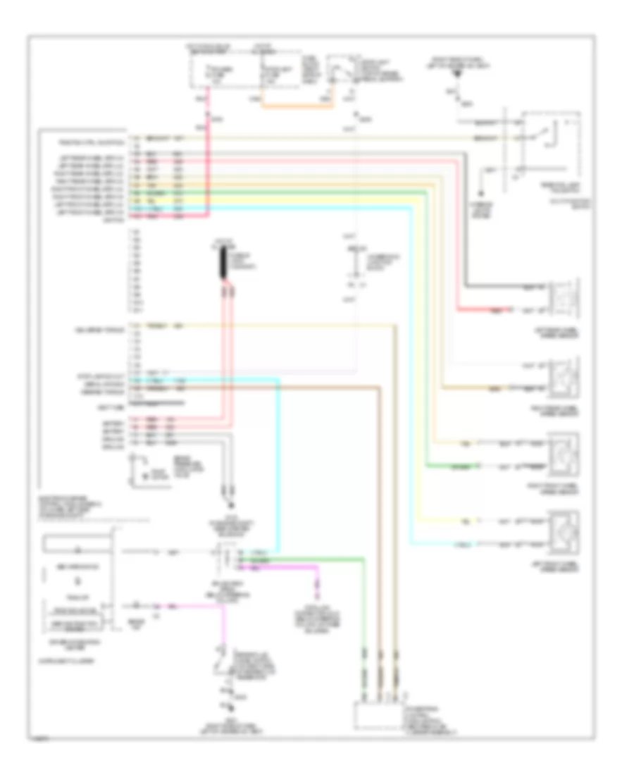
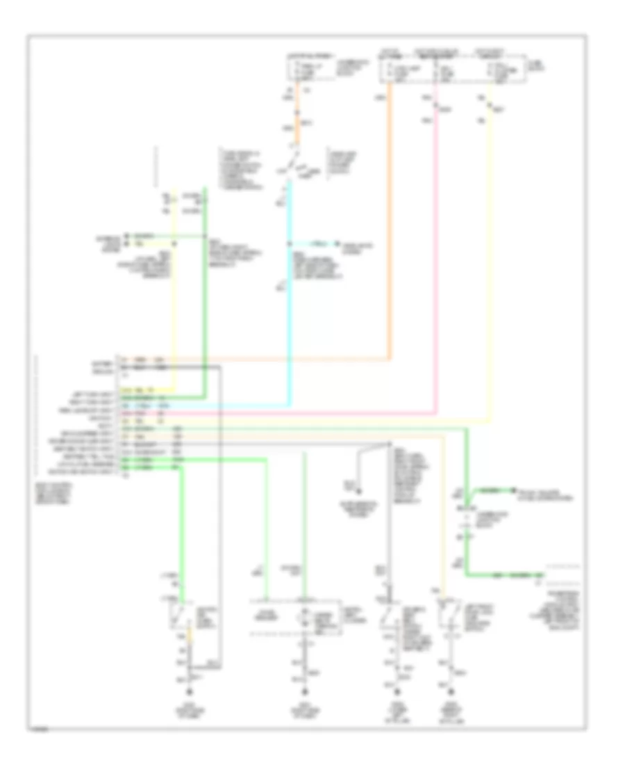
Anti-lock Brake Wiring Diagrams for Oldsmobile Silhouette GL 2001
List of elements for Anti-lock Brake Wiring Diagrams for Oldsmobile Silhouette GL 2001:
- (right side of dash, left of heater-a/c vent) g201
- A10
- A11
- Abs warning ind
- B10
- B11
- Battery
- Brake fluid level switch (on right side of brake fluid reservoir)
- Brake ind
- Brake pressure modulator valve
- C10
- C11
- Data link connector (dlc) (below steering column, on knee bolster)
- Delivered torque
- Desired torque
- Driver information center
- Electronic brake control module (ebcm) (at lower left side of engine compt)
- Fuse block (right side of dash)
- G133 (in engine compt, near starter solenoid)
- G201 (right side of dash, left of heater-a/c vent)
- Ground
- Hot at all times
- Hot in run, bulb test or start
- Ignition
- Instrument cluster
- Interior lights system
- Left front wheel spd (hi)
- Left front wheel spd (lo)
- Left front wheel speed sensor
- Left rear wheel spd (hi)
- Left rear wheel spd (lo)
- Left rear wheel speed sensor
- Multi-function switch
- Nca
- Pcm/abs fuse 10a
- Pnk
- Powertrain control module (pcm) (secured in air cleaner assembly)
- Pump motor
- Rear fog lamp/ tcs switch
- Red
- Right front wheel spd (hi)
- Right front wheel spd (lo)
- Right front wheel speed sensor
- Right rear wheel spd (hi)
- Right rear wheel spd (lo)
- Right rear wheel speed sensor
- S108
- S205
- S230
- S242
- Serial data sig
- Service traction system
- Splice pack sp205 (below steering column)
- Stop lamp sw out
- Stoplamp fuse 15a
- Stoplight switch (top of brake pedal support)
- Tan
- Trac off
- Traction active
- Traction ctrl on/off sig
- Underhood junction block
- Vent tube
ANTI-THEFT
Forced Entry Wiring Diagram for Oldsmobile Silhouette GL 2001
List of elements for Forced Entry Wiring Diagram for Oldsmobile Silhouette GL 2001:
- (body harn, front of left "b" pillar)
- (body harn, under right front seat)
- (right side of dash)
- Ajar indicator switch
- Battery
- Body control module (below right side of dash)
- C11
- C200
- Ctsy lamp fuse 10a
- D10
- D11
- D14
- D15
- Door locks system (door lock switches)
- Driver door lock cylinder switch
- Driver dr ajar in
- Ext lights out
- Exterior lights
- Fuse block
- G201
- G201 (right side of dash, left of heater- a/c vent)
- G305 (base of right "b" pillar)
- G999 (lower left "d" pillar)
- Grd
- Ground
- Horn rly out
- Horns system
- Hot at all times
- Ign key input
- Ignition key alarm switch
- Key cyl lk sw in
- Left front door lock
- Left sliding door jamb switch
- Liftgate lock
- Liftgate lock cylinder switch
- Lock
- Lock input
- Lock out lo
- Nca
- Park lp fuse 20a
- Pass dr ajar in
- Pwr lock fuse 20a
- Radio fuse 10a
- Red/
- Right front door lock
- Right front door lock cylinder switch
- Right sliding door jamb switch
- S202
- S211
- S303
- S309
- S323 (body harn, under left front seat)
- S325
- S327 (body harn, under left front seat)
- S460
- S504
- S604
- Security led
- Shock sensor (behind dash, right of steering column)
- Sliding dr ajar
- Tamper input
- Tan
- Theft deterrent indicator lamp
- Un- lock
- Underhood junction block
- Unlock input
- Vehicle interface unit (viu) (below left side of dash)
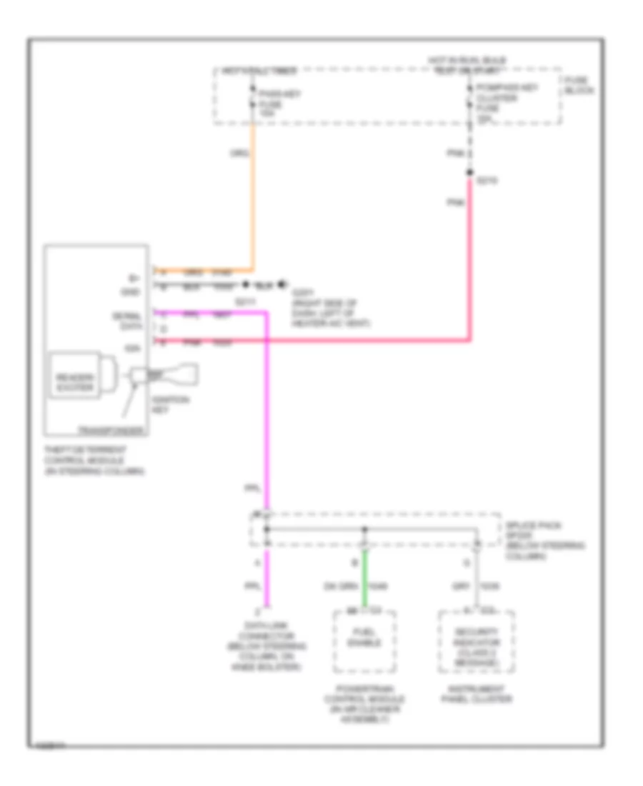
Pass-Key Wiring Diagram for Oldsmobile Silhouette GL 2001
List of elements for Pass-Key Wiring Diagram for Oldsmobile Silhouette GL 2001:
- Data link connector (below steering column, on knee bolster)
- Fuel enable
- Fuse block
- G201 (right side of dash, left of heater-a/c vent)
- Gnd
- Hot at all times
- Hot in run, bulb test or start
- Ign
- Ignition key
- Instrument panel cluster
- Pass-key fuse 10a
- Pcm/pass key cluster fuse 10a
- Pnk
- Powertrain control module (in air cleaner assembly)
- Reader/ exciter
- S210
- S211
- Security indicator (class 2 message)
- Serial data
- Splice pack sp205 (below steering column)
- Theft deterrent control module (in steering column)
- Transponder
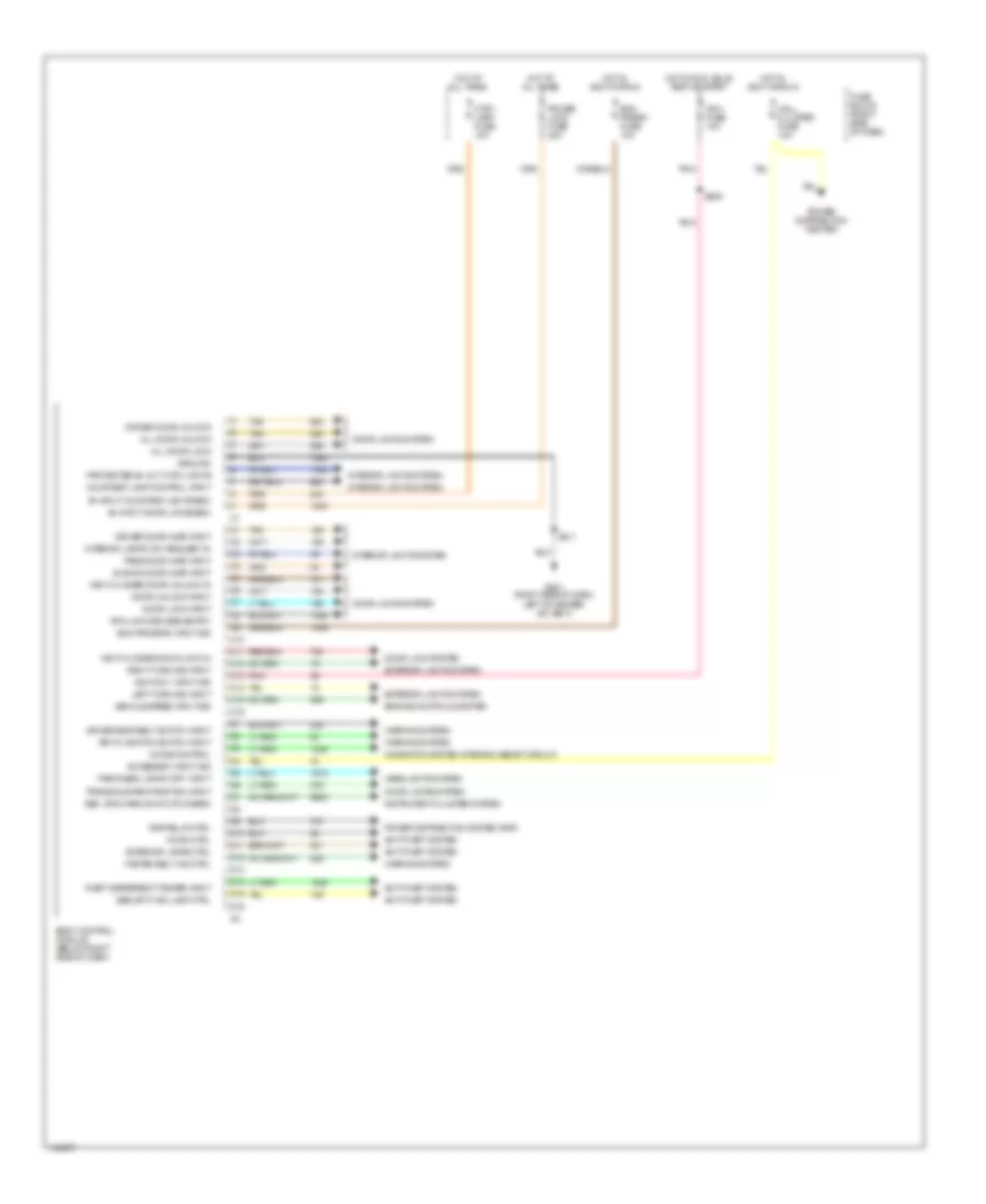
BODY COMPUTER
Body Computer Wiring Diagrams for Oldsmobile Silhouette GL 2001
List of elements for Body Computer Wiring Diagrams for Oldsmobile Silhouette GL 2001:
- Accessory input sig
- All door lock
- All door unlock
- Anti-theft system
- B+ input courtesy lights/bcm
- B+ input door locks/bcm
- Bcm prgrm fuse 10a
- Bcm program input sig
- Body control module (below right side of dash)
- C10
- C11
- C12
- C13
- C14
- C15
- C16
- Chime control
- Courtesy lamp control input
- Ctsy lamp fuse 10a
- D10
- D11
- D12
- D13
- D14
- D15
- D16
- Door lock input
- Door lock system
- Door locks system
- Door unlock input
- Driver door ajar input
- Driver door unlock
- Driver seat belt switch input
- Engine controls system
- Exterior lamps ctrl
- Exterior lights system
- Fasten belt ind ctrl
- Fuse block (right side of dash)
- G201 (right side of dash, left of heater- a/c vent)
- Ground
- Headlights system
- Horn ctrl
- Hot at all times
- Hot in accy or run
- Hot in run, bulb test or start
- Ign 1 fuse 10a
- Ignition 1 input sig
- Instrument cluster system
- Interior lamps "on" request in
- Interior lights system
- Key cylinder door lock in
- Key cylinder door unlock in
- Key in ignition switch input
- Left turn sig input
- Mall cluster fuse 10a
- Navigation system (parking assist circuit)
- Park/head lamps "off" input
- Pass door ajar input
- Pnk
- Power distribution center
- Power distribution system (rap)
- Power lock fuse 20a
- Protected b+ out ctsy lights
- Rap relay ctrl
- Rfa link (keyless entry)
- Right turn sig input
- S209
- S211
- Sec. sys warn away ctd disarm
- Security ind lamp ctrl
- Sliding door ajar input
- Tan
- Theft deterrent tamper input
- Transaxle park position input
- Vehicle speed input sig
- Warning system
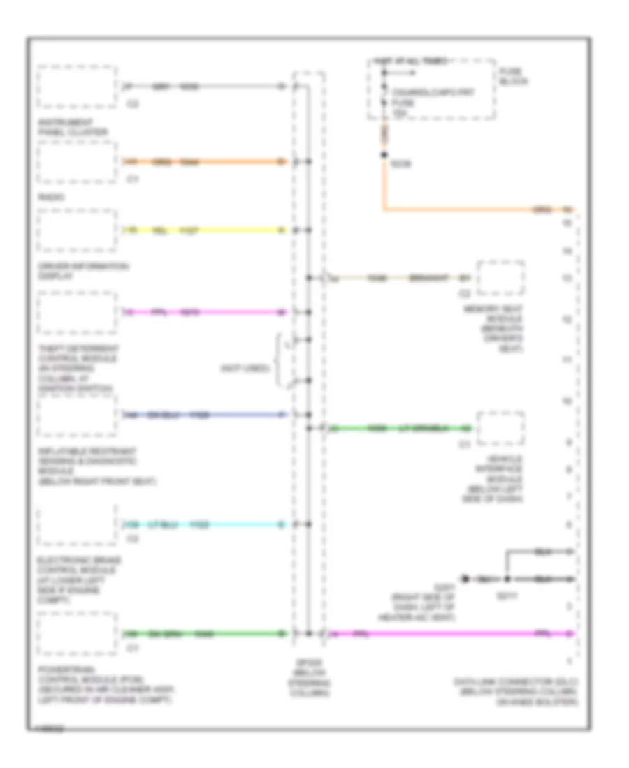
COMPUTER DATA LINES
Computer Data Lines for Oldsmobile Silhouette GL 2001
List of elements for Computer Data Lines for Oldsmobile Silhouette GL 2001:
- (not used)
- Cigar/dlc/apo frt fuse 15a
- Data link connector (dlc) (below steering column, on knee bolster)
- Driver information display
- Electronic brake control module (at lower left side if engine compt)
- Fuse block
- G201 (right side of dash, left of heater-a/c vent)
- Hot at all times
- Inflatable restraint sensing & diagnostic module (below right front seat)
- Instrument panel cluster
- Memory seat module (beneath driver's seat)
- Powertrain control module (pcm) (secured in air cleaner assy, left front of engine compt)
- Radio
- S211
- S238
- Sp205 (below steering column)
- Theft deterrent control module (in steering column, at ignition switch)
- Vehicle interface module (below left side of dash)
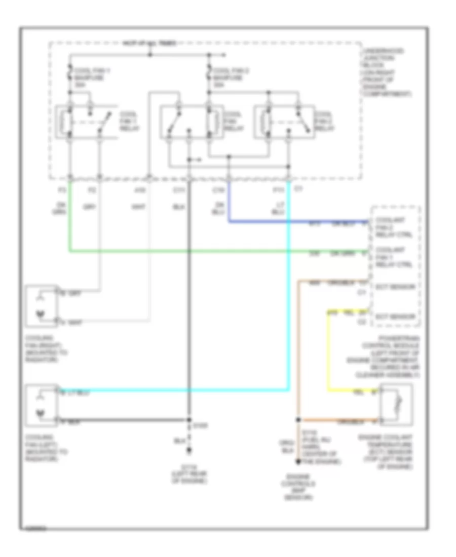
COOLING FAN
Cooling Fan Wiring Diagram for Oldsmobile Silhouette GL 2001
List of elements for Cooling Fan Wiring Diagram for Oldsmobile Silhouette GL 2001:
- A10
- C10
- C11
- Cool fan 1 maxifuse 30a
- Cool fan 1 relay
- Cool fan 2 maxifuse 30a
- Cool fan 2 relay
- Cool fan relay
- Coolant fan 1 relay ctrl
- Coolant fan 2 relay ctrl
- Cooling fan (left) (mounted to radiator)
- Cooling fan (right) (mounted to radiator)
- Ect sensor
- Engine controls (map sensor)
- Engine coolant temperature (ect) sensor (top left rear of engine)
- F11
- G114 (left rear of engine)
- Hot at all times
- Powertrain control module (left front of engine compartment, secured in air cleaner assembly)
- S105
- S110 (fuel inj harn, center of the engine)
- Underhood junction block (on right front of engine compartment)
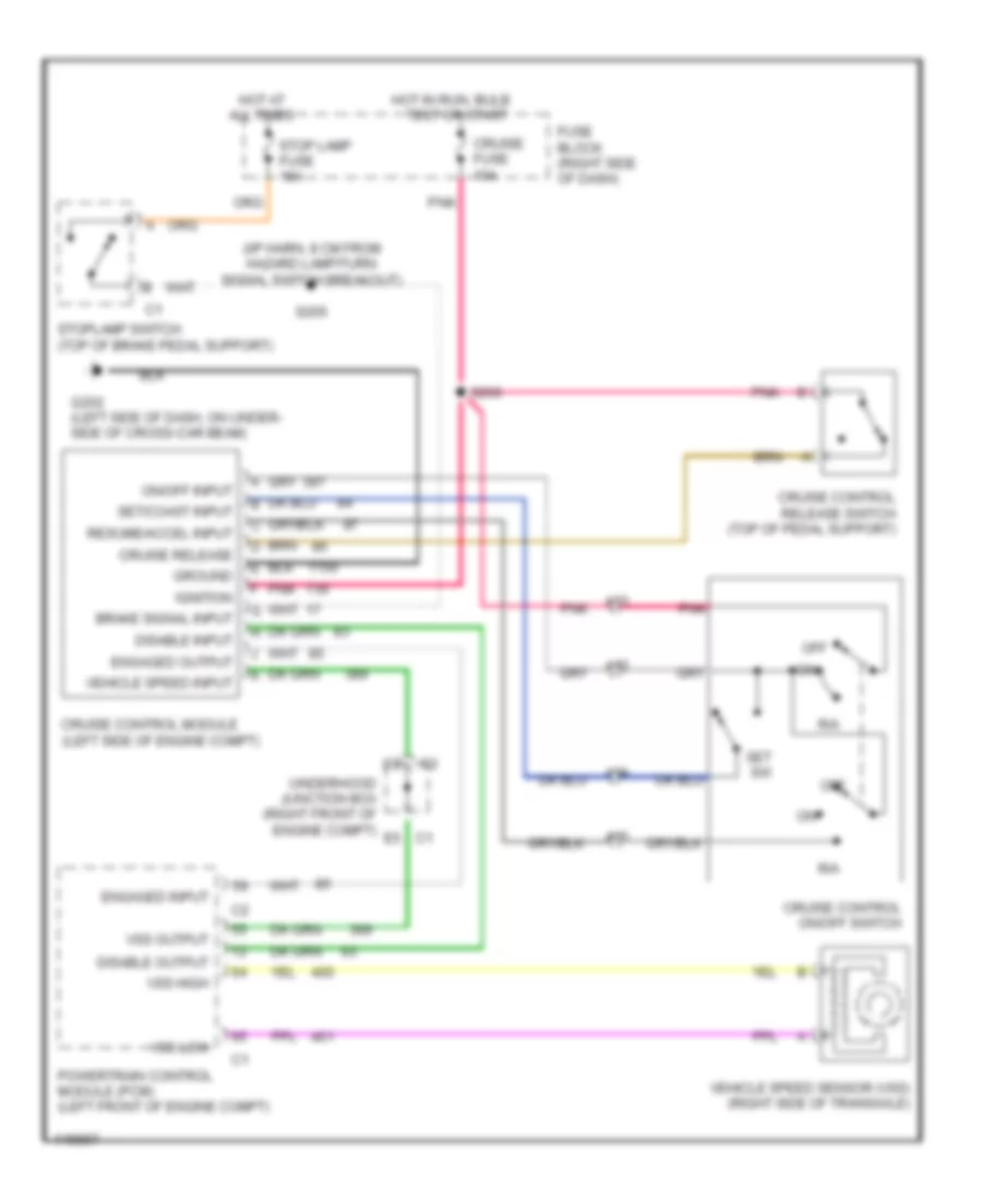
CRUISE CONTROL
Cruise Control Wiring Diagram for Oldsmobile Silhouette GL 2001
List of elements for Cruise Control Wiring Diagram for Oldsmobile Silhouette GL 2001:
- (i/p harn, 8 cm from hazard lamp/turn signal switch breakout)
- A12
- A13
- A14
- A15
- All times
- Brake signal input
- C1 e5
- Cruise control module (left side of engine compt)
- Cruise control on/off switch
- Cruise control release switch (top of pedal support)
- Cruise fuse 10a
- Cruise release
- Disable input
- Disable output
- Engaged input
- Engaged output
- Fuse block (right side of dash)
- G202 (left side of dash, on under- side of cross-car beam)
- Ground
- Hot at
- Hot in run, bulb
- Ignition
- Off
- On/off input
- Pnk
- Powertrain control module (pcm) (left front of engine compt)
- R/a
- Resume/accel input
- S205
- S266
- Set sw
- Set/coast input
- Stop lamp fuse 15a
- Stoplamp switch (top of brake pedal support)
- Test or start
- Underhood junction box (right front of engine compt)
- Vehicle speed input
- Vehicle speed sensor (vss) (right side of transaxle)
- Vss high
- Vss low
- Vss output
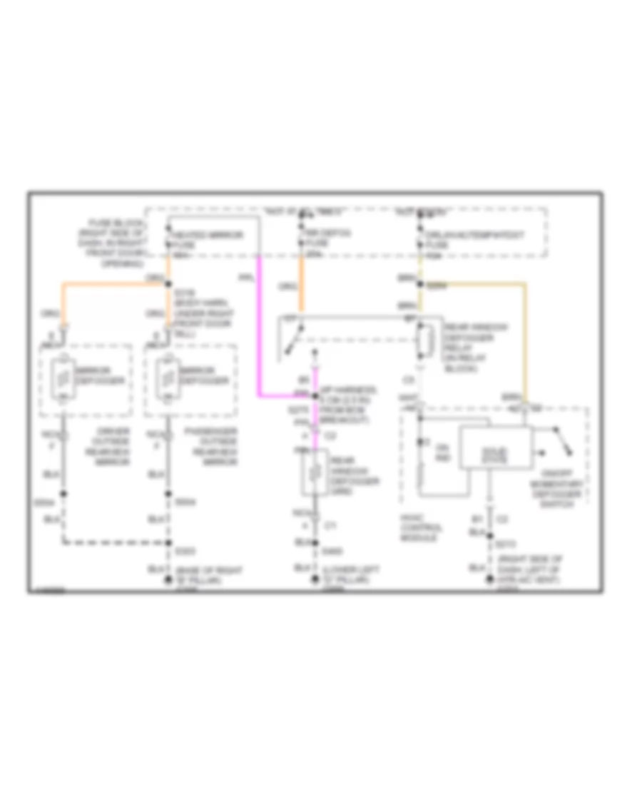
DEFOGGERS
Defogger Wiring Diagram for Oldsmobile Silhouette GL 2001
List of elements for Defogger Wiring Diagram for Oldsmobile Silhouette GL 2001:
- (lower left "d" pillar) g999
- (right side of dash, left of htr-a/c vent) g201
- Driver outside rearview mirror
- Drl/hvac/temp/htdst fuse 10a
- E nca
- Front door sill)
- Fuse block (right side of dash, in right front door opening)
- Heated mirror fuse 10a
- Hot at all times
- Hot in run
- Hvac control module
- Mirror defogger
- Nca
- On ind
- On/off momentary defogger switch
- Passenger outside rearview mirror
- Rear window defogger grid
- Rear window defogger relay (in relay block)
- Rr defog fuse 30a
- S213
- S264
- S275
- S303
- S460
- S504
- S604
- Solid state
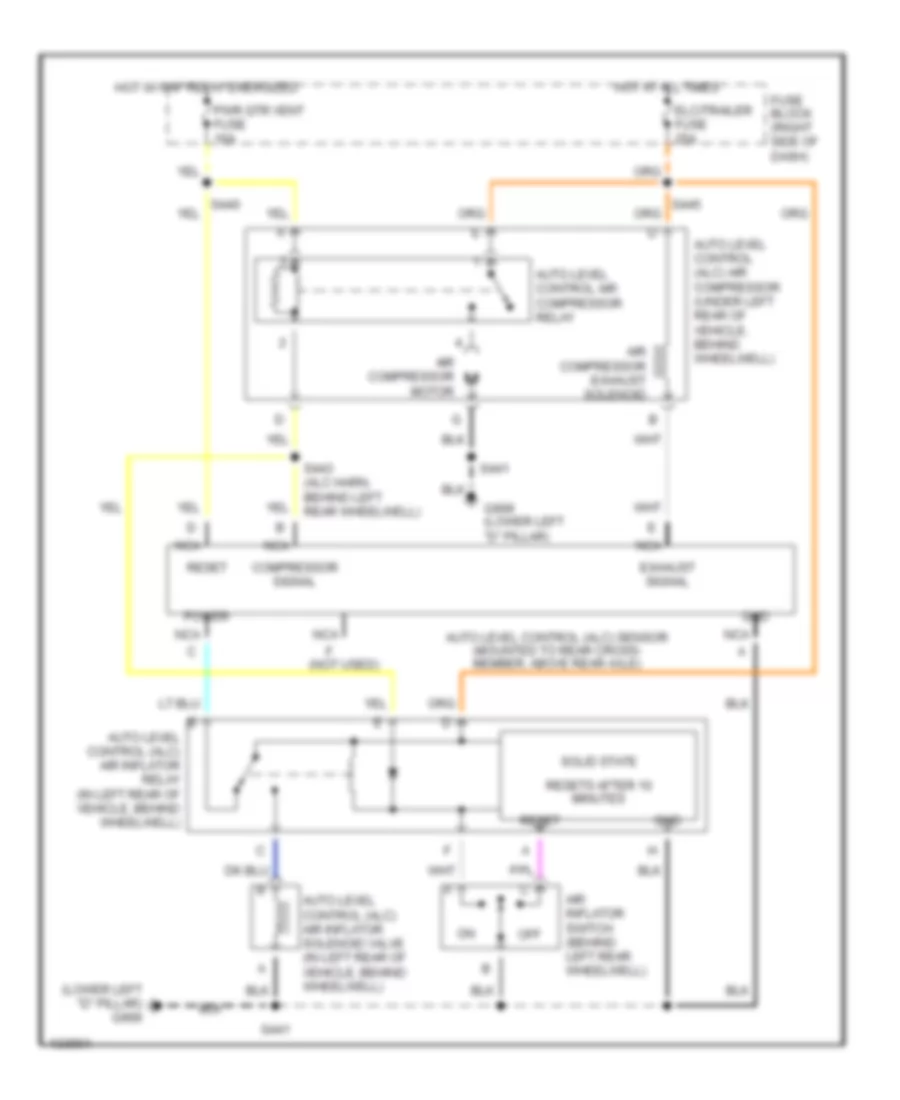
ELECTRONIC SUSPENSION
Electronic Suspension Wiring Diagram, with Inflator for Oldsmobile Silhouette GL 2001
List of elements for Electronic Suspension Wiring Diagram, with Inflator for Oldsmobile Silhouette GL 2001:
- (lower left "d" pillar) g999
- (not used)
- Air compressor exhaust solenoid
- Air compressor motor
- Air inflator switch (behind left rear wheelwell)
- Auto level control (alc) air compressor (under left rear of vehicle, behind wheelwell)
- Auto level control (alc) air inflator relay (in left rear of vehicle, behind wheelwell)
- Auto level control (alc) air inflator solenoid valve (in left rear of vehicle, behind wheelwell)
- Auto level control (alc) sensor (mounted to rear cross- member, above rear axle)
- Auto level control air compressor relay
- Compressor signal
- Elc/trailer fuse 25a
- Exhaust signal
- Fuse block (right side of dash)
- G999 (lower left "d" pillar)
- Gnd
- Hot at all times
- Hot w/ rap relay energized
- Nca
- Off
- Power
- Pwr qtr vent fuse 10a
- Reset
- Resets after 10 minutes
- S441
- S443 (alc harn, behind left rear wheelwell)
- Solid state
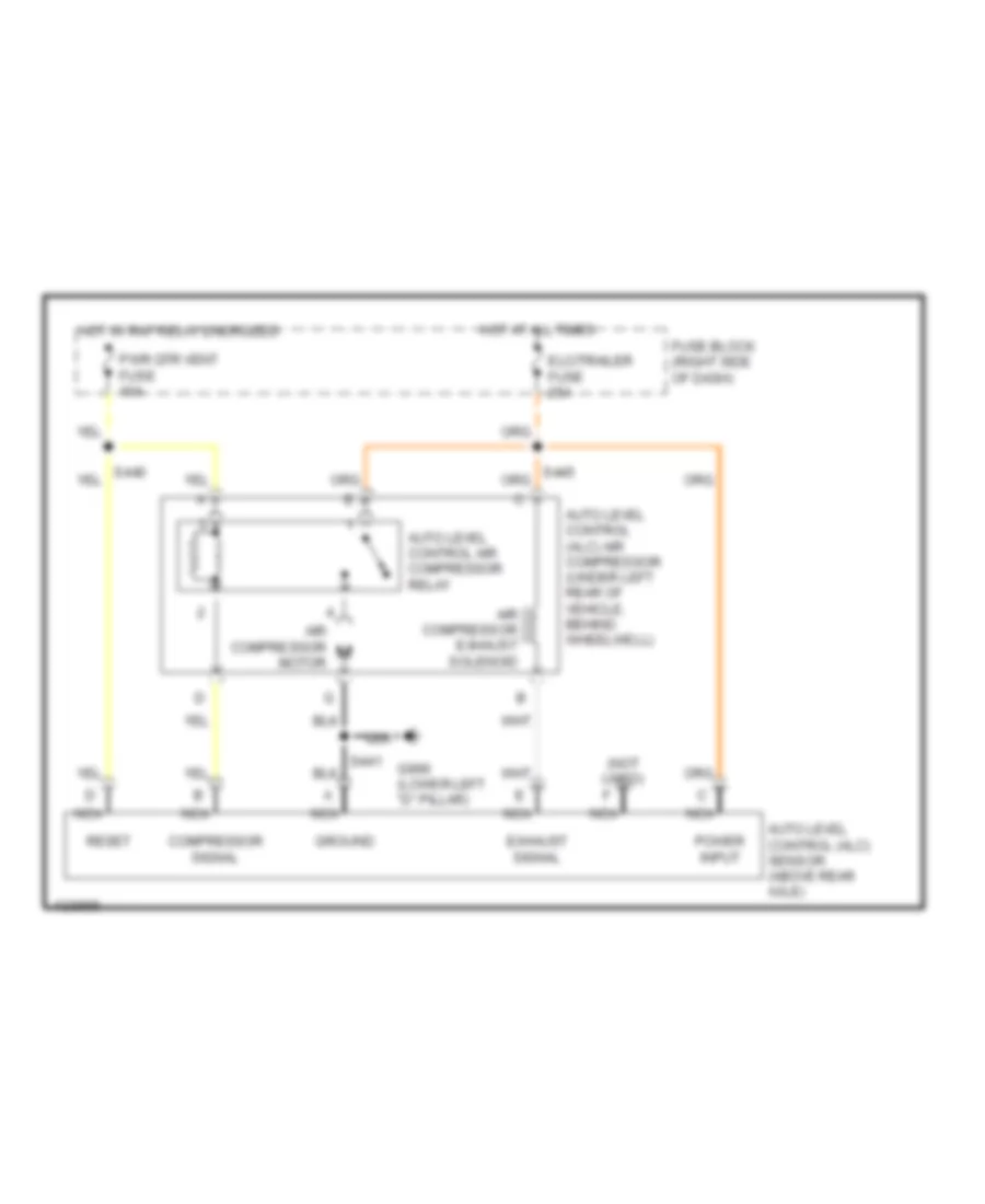
Electronic Suspension Wiring Diagram, without Inflator for Oldsmobile Silhouette GL 2001
List of elements for Electronic Suspension Wiring Diagram, without Inflator for Oldsmobile Silhouette GL 2001:
- (not used)
- Air compressor exhaust solenoid
- Air compressor motor
- Auto level control (alc) air compressor (under left rear of vehicle, behind wheelwell)
- Auto level control (alc) sensor (above rear axle)
- Auto level control air compressor relay
- Compressor signal
- Elc/trailer fuse 25a
- Exhaust signal
- Fuse block (right side of dash)
- G999 (lower left "d" pillar)
- Ground
- Hot at all times
- Hot w/ rap relay energized
- Nca
- Power input
- Pwr qtr vent fuse 10a
- Reset
ENGINE PERFORMANCE
3.4L
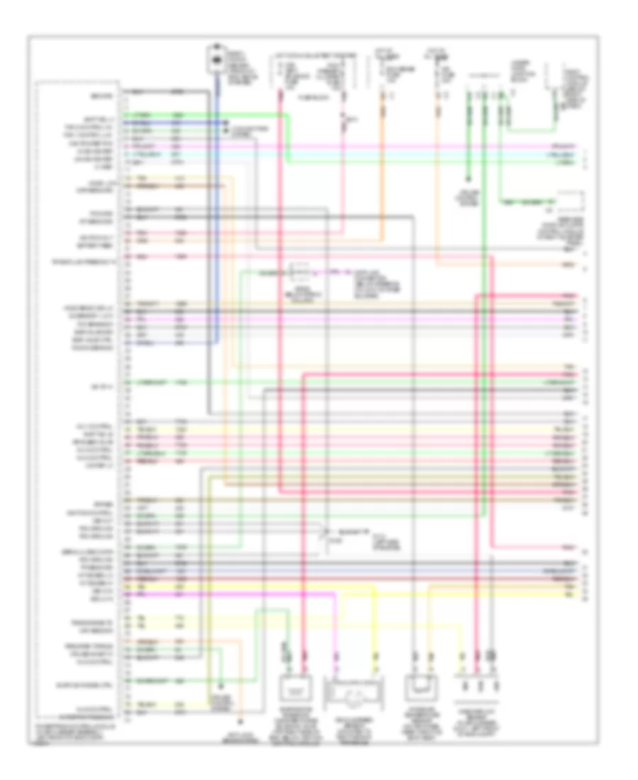
3.4L VIN E, Engine Performance Wiring Diagrams (1 of 4) for Oldsmobile Silhouette GL 2001
List of elements for 3.4L VIN E, Engine Performance Wiring Diagrams (1 of 4) for Oldsmobile Silhouette GL 2001:
- (3x) ref lo
- 24x ign sig ref
- 3x ign sig ref
- 5 v ref
- A/c refrig press sig
- A/t iss sen hi
- A/t iss sen lo
- Air bleed valve
- Air fuse 30a
- Anti-lock brake system
- Bank 1 knock sensor (front of eng, above starter)
- Battery feed
- Body control module (below right side of dash)
- Bypass
- C15
- Cam pos ref pcm
- Can vent solenoid fuse 10a
- Cooling fans system
- Cruise control system
- Cruise inhibit in
- Data link connector (below steering column, on knee bolster)
- Ecm sense fuse 10a
- Egr valve ctrl
- Egr valve grd
- Evap can purge ctrl
- Evaporative emissions canister purge solenoid valve (top right side of eng, below ignition control module)
- Fan 1 control (lo)
- Fan 2 control (hi)
- Fuse block
- G112 (left side of engine)
- Gnd
- Ho2s sens 2 sig lo
- Ho2s1 low
- Hot at all times
- Hot in run, bulb test or start
- Iac "b" hi
- Iat sens grd
- Ign pos volt
- Ignition control
- Inj 1 control
- Inj 2 control
- Inj 3 control
- Inj 5 control
- Inj 6 control
- Intake air temperature sensor (on air intake, near throttle body assy)
- Knock sens sig
- Maf
- Maf sens sig
- Map sens grd
- Mass airflow sensor (in air cleaner duct, left front of eng compt)
- O2 sensor 1 low
- Pcm grd
- Pcm ground
- Pcm/ passkey cluster fuse 10a
- Pnk
- Powertrain control module (in air cleaner assembly, left front of eng compt)
- Pwr
- Rear side door actuator control module (in right quarter panel)
- Required torque
- S106
- S210
- Sen grd
- Serial class 2 data
- Shift sol a
- Shift sol b
- Sp205 (below strng column)
- Tan
- Tcc brake sw
- Tp sens grd
- Trans fluid press sw "a"
- Trans range "b"
- Under- hood junction block
- Vehicle speed sensor (mounted to right side of transaxle)
- Vss hi in
- Vss lo in
- Vss out
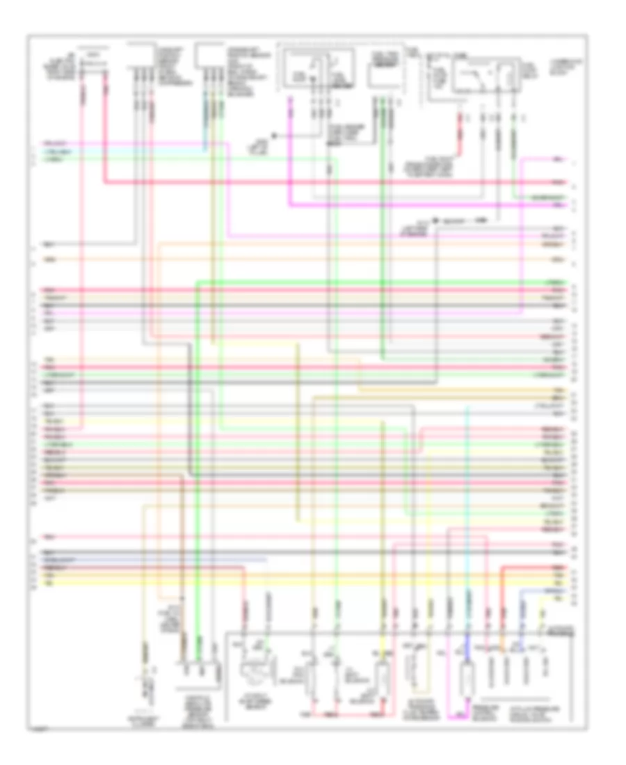
3.4L VIN E, Engine Performance Wiring Diagrams (2 of 4) for Oldsmobile Silhouette GL 2001
List of elements for 3.4L VIN E, Engine Performance Wiring Diagrams (2 of 4) for Oldsmobile Silhouette GL 2001:
- (fuel sender harn, near fuel tank) s329
- (left side of engine)
- 1-2 shift solenoid
- 2-3 shift solenoid
- 5v ref
- A/t fluid pressure manual valve position switch
- A/t input shaft speed sensor
- Air injection bleed valve (right side of engine) b
- Automatic transaxle
- Automatic transaxle fluid temper- ature sensor
- B tcc sw
- C d4 & d2 sw
- Camshaft position sensor (front of eng, above a/c compressor)
- Crankshaft position sensor (24x) (front of eng, at end of crankshaft, behind harmonic balancer)
- D d3 & d2 sw
- E lo & rev sw
- Fuel level sender
- Fuel pump
- Fuel pump fuse 15a
- Fuel pump prime connector (on eng harn, next to battery conn)
- Fuel pump relay
- Fuel tank
- Fuel tank pressure sensor
- G mil ind (chk eng)
- G112
- G308 (left "b" pillar)
- Hot at all times
- Instrument cluster
- Manifold absolute pressure sensor (top right side of eng)
- Map
- Nca
- Pnk
- Pressure control solenoid
- Red
- Rtn
- S106
- S110 (fuel inj harn, center of eng)
- Tan
- Tcc pwm solenoid
- Underhood junction block
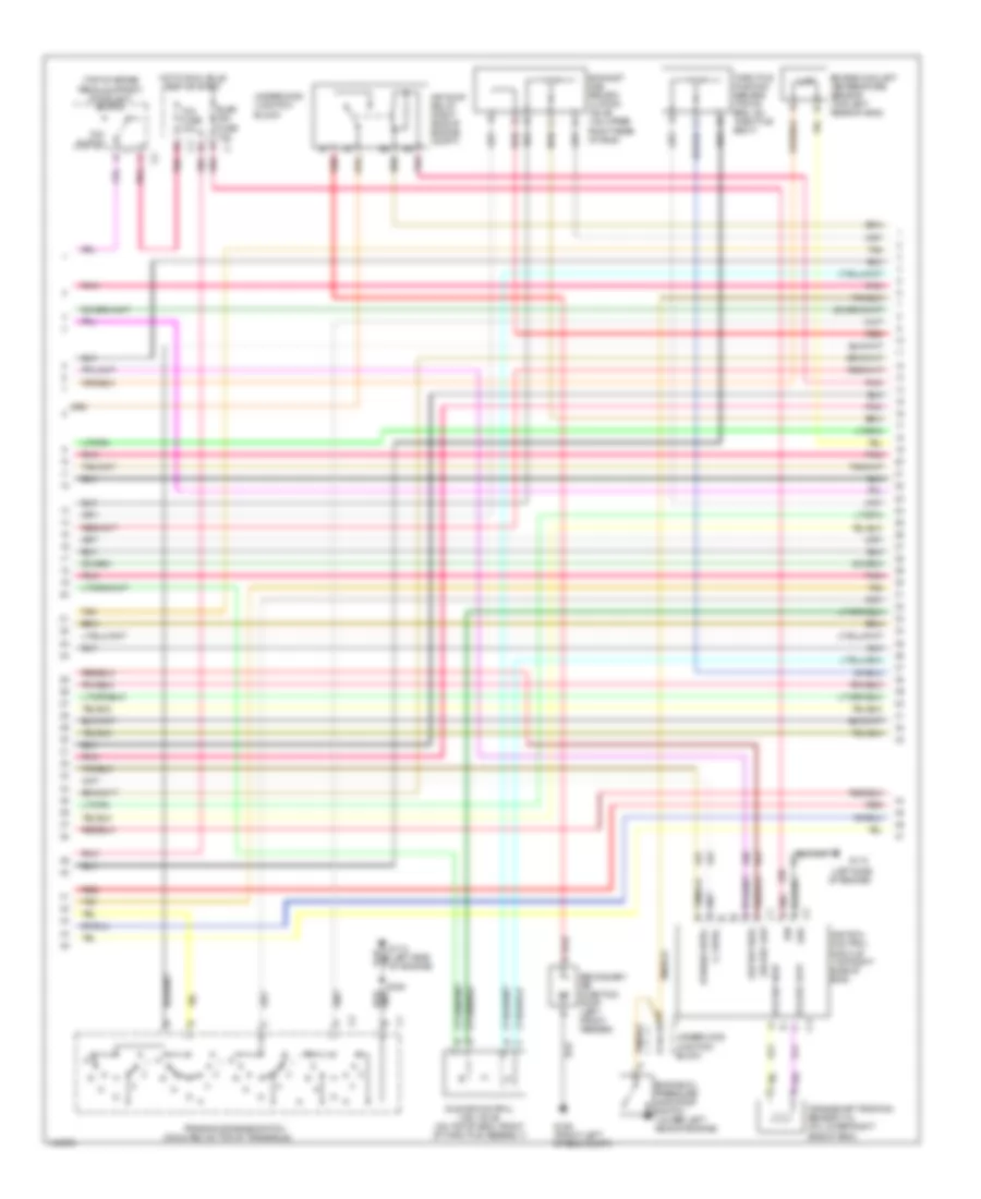
3.4L VIN E, Engine Performance Wiring Diagrams (3 of 4) for Oldsmobile Silhouette GL 2001
List of elements for 3.4L VIN E, Engine Performance Wiring Diagrams (3 of 4) for Oldsmobile Silhouette GL 2001:
- (3x) ref high
- (3x) ref low
- (7x) ref high
- (7x) ref low
- (left side of engine)
- (mounted on top of transaxle)
- (top of brake pedal support) stoplight switch
- Air pump relay (right side of engine compt)
- Bypass cntrl
- C2 grd
- Crankshaft position sensor (7x) (on lower right side of eng)
- D12
- Elek ign fuse 10a
- Engine coolant temperature sensor (top left rear of eng)
- Engine oil pressure indicator switch (lower left side of engine)
- Exhaust gas recirc- ulation valve (on upper right rear of eng)
- G106 (front left of eng compt)
- G112
- G112 (left side of engine)
- Hot in run, bulb test or start
- Ic cntrl
- Idle air control (iac) valve (on top of eng, front of throttle assembly)
- Ign
- Ignition control module (top right side of eng)
- Pnk
- Pnk b
- Red
- Red a
- S106
- Secondary air injection pump (left front fender)
- Tan
- Tcc fuse 10a
- Tcc switch
- Throttle position sensor (top of eng, on throttle body)
- Transaxle range switch
- Underhood junction block
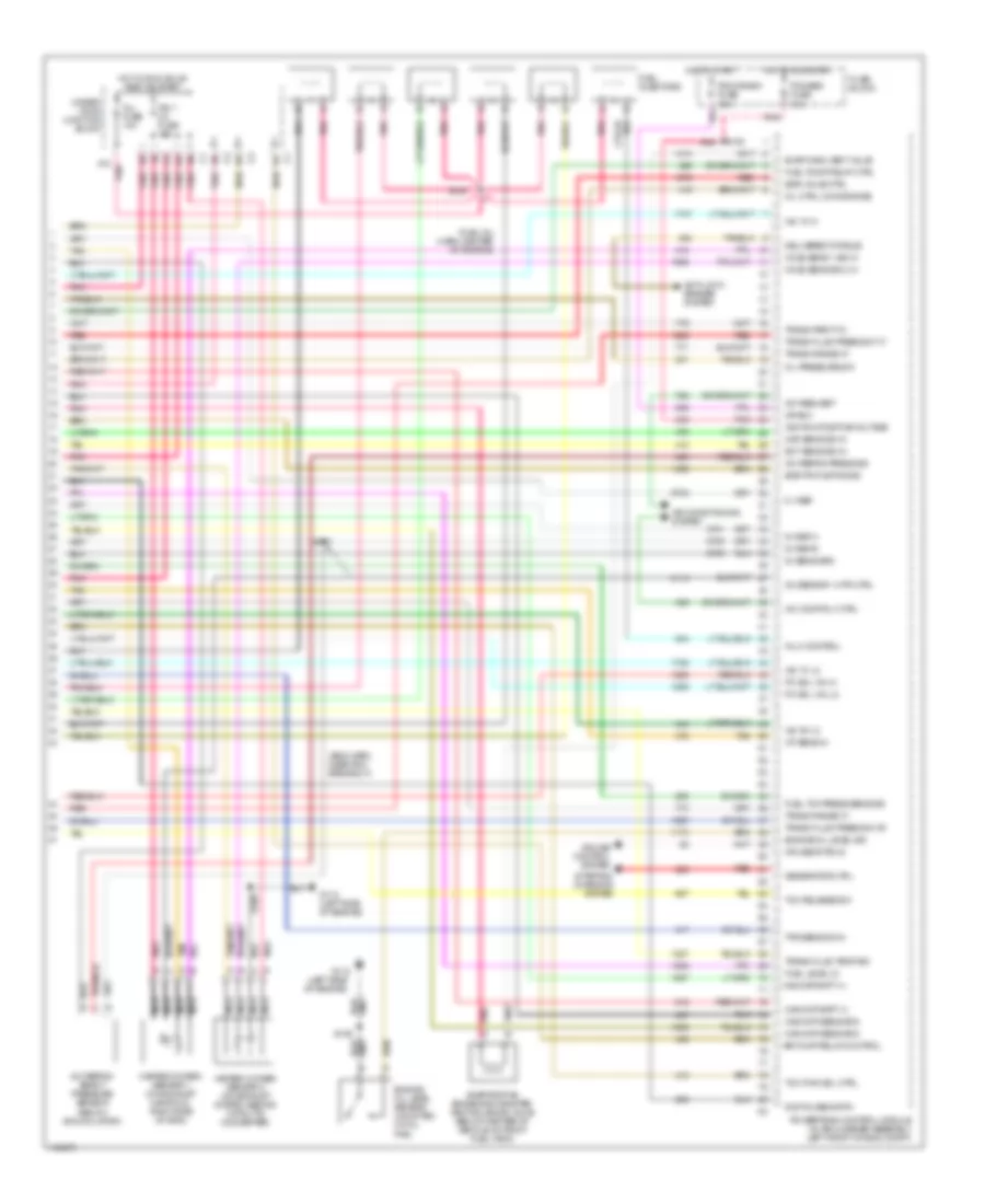
3.4L VIN E, Engine Performance Wiring Diagrams (4 of 4) for Oldsmobile Silhouette GL 2001
List of elements for 3.4L VIN E, Engine Performance Wiring Diagrams (4 of 4) for Oldsmobile Silhouette GL 2001:
- (eng harn, near pcm breakout)
- (fuel inj harn, center of engine)
- (left side of engine)
- 5 v ref
- 5v ref a
- 5v ref b
- 5v sens grd
- A/c comp rly ctrl
- A/c refrig press sig
- A/c refrig- erant pressure sensor (below accumulator)
- A/c request
- A12 pnk
- Air conditioning system
- Air pump relay control
- Anti-lock brakes system
- Cam/ckp batt (+)
- Cam/ckp sens grd
- Crank
- Cruise control system
- Cruise status
- D9 c3
- Delivered torque
- Digital sens rtn
- E9 c1
- Ect sens sig in
- Egr pintle pos sig
- Egr valve ctrl
- Engine oil level sensor (mounted on oil pan)
- Engine oil level sig
- Evap cann vent valve
- Evaporative emissions canister vent solenoid valve (below center of vehicle, in front fuel tank)
- Fuel injectors
- Fuel level in
- Fuel pump relay ctrl
- Fuel tnk press sens sig
- Fuse block
- G112
- G112 (left side of engine)
- Generator ctrl
- Heated oxygen sensor 1 (on exhaust manifold, right side of eng)
- Heated oxygen sensor 2 (on exhaust system, behind catalytic converter)
- Ho2s sens 1 sig hi
- Ho2s sens sig 2 hi
- Hot in run, bulb test or start
- Hot in run/start
- Hot in start
- Iac "a" hi
- Iac "a" lo
- Iac "b" lo
- Iat sens in
- Ign 1 uh fuse 15a
- Ignition positive voltage
- Inj 4 control
- Inj fuse 10a
- Map sens sig in
- Mil ctrl (chk engine)
- Nca
- O2 sensor 1 htr ctrl
- Oil pressure sw
- Pc sol val hi
- Pc sol val lo
- Pcm/abs fuse 10a
- Pcm/crank fuse 10a
- Pnk
- Powertrain control module (in air cleaner assembly, left front of eng compt)
- Red
- S105
- S106
- S108
- S109
- S167
- Starting/ charging system
- Tan
- Tcc pwm sol ctrl
- Tcc release sw
- Tps sens sig in
- Trans fluid press sw "b"
- Trans fluid press sw "c"
- Trans fluid temp sig
- Trans parity in
- Trans range "a"
- Trans range "c"
- Under- hood junction block
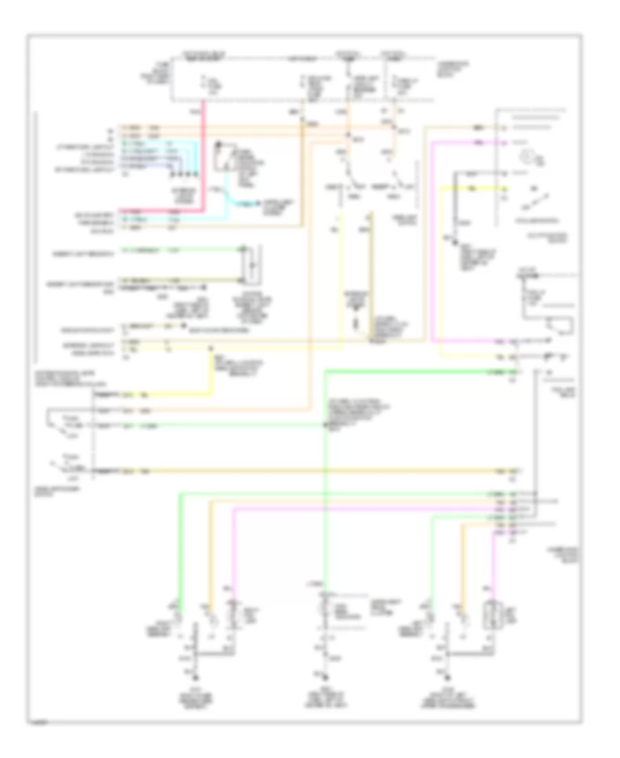
EXTERIOR LIGHTS
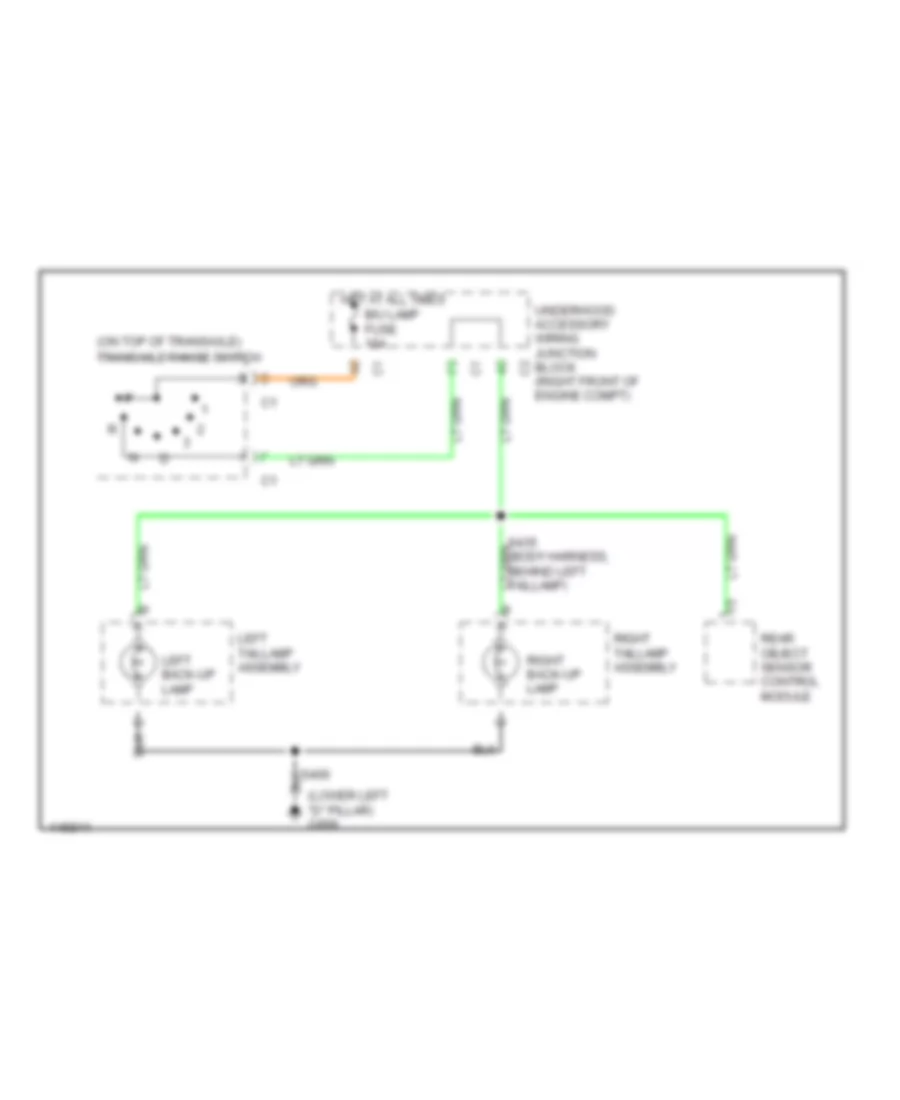
Back-up Lamps Wiring Diagram for Oldsmobile Silhouette GL 2001
List of elements for Back-up Lamps Wiring Diagram for Oldsmobile Silhouette GL 2001:
- (lower left "d" pillar) g999
- (on top of transaxle) transaxle range switch
- B/u lamp fuse 10a
- Hot at all times
- Left back-up lamp
- Left taillamp assembly
- Rear object sensor control module
- Right back-up lamp
- Right taillamp assembly
- S406
- S435 (body harness, behind left taillamp)
- Underhood accessory wiring junction block (right front of engine compt)
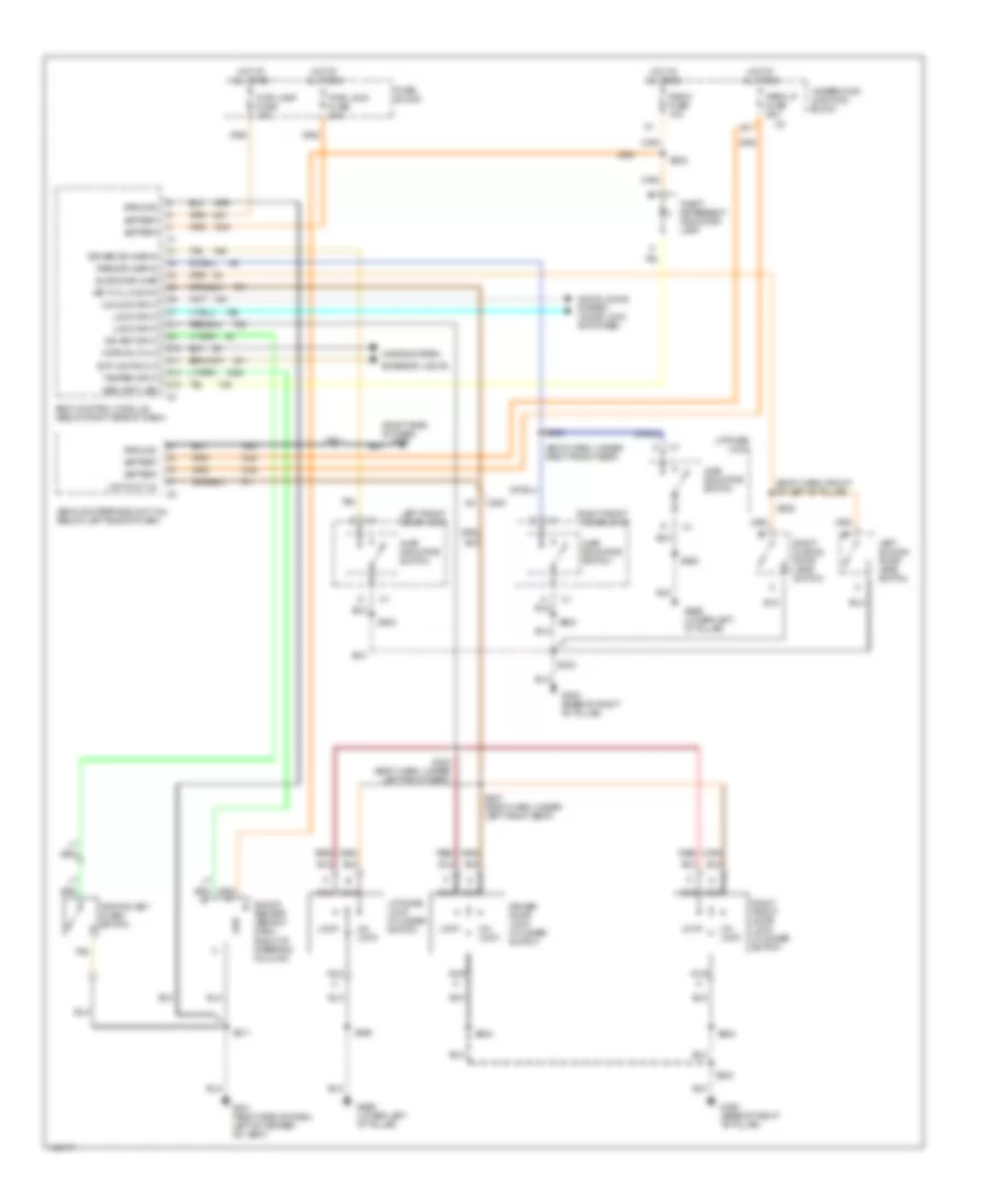
Exterior Lamps Wiring Diagram (1 of 2) for Oldsmobile Silhouette GL 2001
List of elements for Exterior Lamps Wiring Diagram (1 of 2) for Oldsmobile Silhouette GL 2001:
- (dash harn, 10 cm from radio conn breakout)
- Battery (b+)
- Body control module (below right side of dash)
- C12
- C14
- Daytime running lamps (drl) control module (behind dash, right side of steering column)
- Ext lamps ctrl
- Fuse block
- G201 (right side of dash, left of heater-a/c vent)
- Hazard fuse 15a
- Hazard lamp/ turn signal flasher (below left side of dash, left side base of steering column)
- Head
- Headlamp & i/p lamp dimmer switch
- Headlights (foglamps)
- Hot at all times
- Hot in run, bulb test or start
- Instrument cluster
- Left turn in
- Lft turn in
- Lft turn out
- Off
- Park
- Park lp fuse 20a
- Pnk
- Right turn in
- Rt turn in
- Rt turn out
- S204
- S212
- S232 (dash harness)
- S233 (dash harness, left side of dash, 4 cm from radio conn breakout)
- S242
- T/sig fuse 10a
- Turn signal switch
- Underhood accessory wiring junction block
- Vehicle interference unit
Exterior Lamps Wiring Diagram (2 of 2) for Oldsmobile Silhouette GL 2001
List of elements for Exterior Lamps Wiring Diagram (2 of 2) for Oldsmobile Silhouette GL 2001:
- (body harn, behind left taillamp) s411
- (body harn, behind left taillamp) s431
- (liftgate harn, 7 cm from lift- gate lock) s457
- A10
- A11
- A12
- B11
- C11
- Center high mounted stop lamp (chmsl)
- D11
- E11
- Elc fuse 20a
- F10
- F11
- F12
- Fuse block
- G101 (right inner fender, near battery)
- G108 (right side of left headlamp, on support)
- G999 (lower left "d" pillar)
- Hot at all times
- Left front park/turn lamp
- Left front side marker
- Left rear tail lamp
- Left rear tail/stop lamp
- Left rear turn signal lamp
- Left taillamp assembly
- License lamps
- Right front park/turn lamp
- Right front side marker
- Right rear tail lamp
- Right rear tail/stop lamp
- Right rear turn signal lamp
- Right taillamp assembly
- S123
- S124
- S205 (dash harn, 8 cm from hazard/ turn lamp flasher breakout)
- S405 (body harness, 4 cm from left taillight breakout)
- S406
- S441
- S445
- S460
- Stop lamp fuse 15a
- Stop lamp switch (on brake pedal support)
- Trailer wiring harness (wires cut & taped)
- Underhood accessory wiring junction block
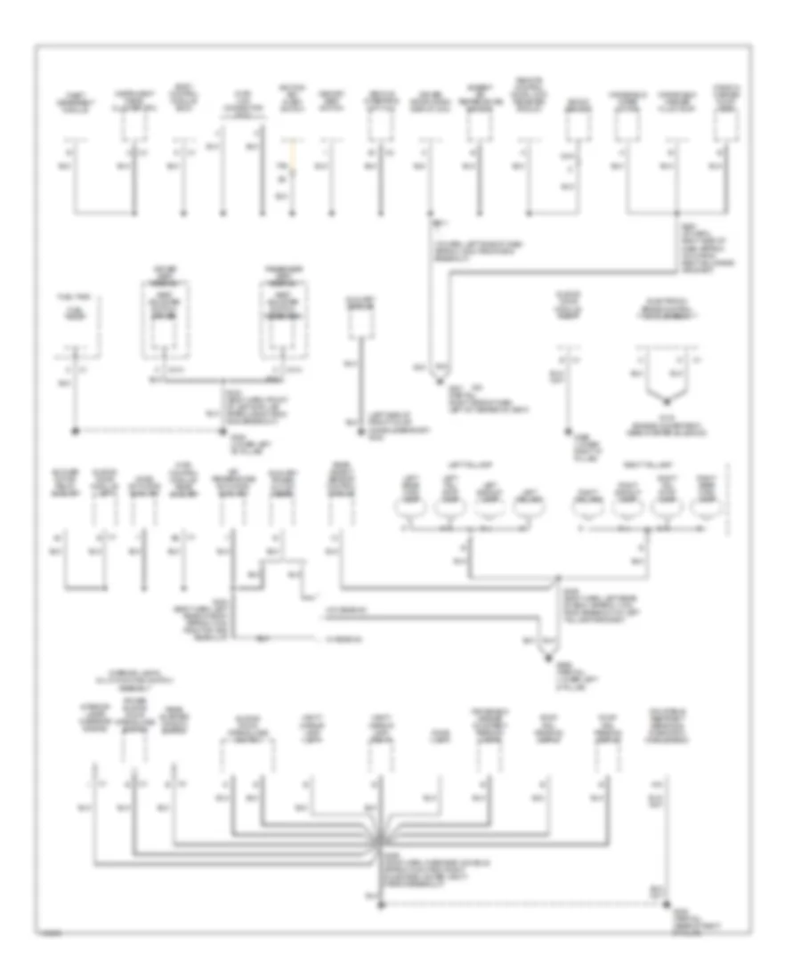
GROUND DISTRIBUTION
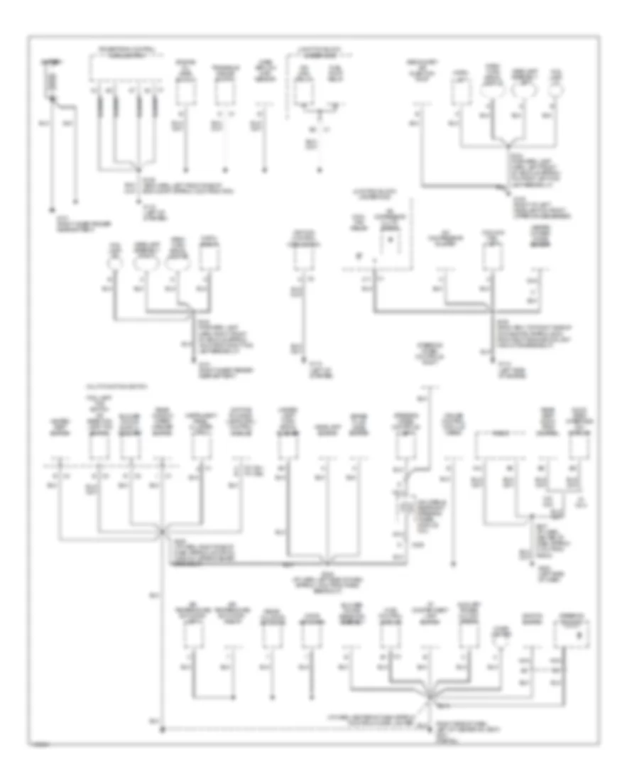
Ground Distribution Wiring Diagram (1 of 3) for Oldsmobile Silhouette GL 2001
List of elements for Ground Distribution Wiring Diagram (1 of 3) for Oldsmobile Silhouette GL 2001:
- (i/p harn, center of dash approx 72cm from cigar lighter)
- (right side of dash, left of heater-a/c vent) g201 (partial)
- (t61) (t65)
- A b
- A/c compressor clutch
- A/c copressor cluth diode
- A12
- Air temperature actuator- left
- Air temperature actuator- right
- Audio video interface (avi) module
- Auxiliary power outlet- front
- Battery
- Blower motor resistor assembly
- Blower motor switch- auxiliary
- Brake fluid level switch
- C11
- C2 c2
- C205
- Cigar lighter
- Cool fan relay
- Cooling fan- left
- Cruise control module (ccm)
- Daytime running lamps (drl) control module
- Engine oil level switch
- Fog lamp- lf
- Fog lamp- rf
- Fog lamp/ tcs switch
- Fuel pump relay
- G101 (right inner fender near battery)
- G108 (right of left headlamp on front upper crossmember)
- G110 (left of starter)
- G112 (left side of engine)
- G202 (left side of dash)
- Hazard lamp/ turn signal flasher
- Headlamp assembly- left
- Headlamp assembly- right
- Headlamp switch
- Heated oxygen (ho2s) sensor
- Heated seat switch
- Horn-
- Hvac control module
- I/p compartment lamp switch
- Ign main relay
- Ignition control module (icm)
- Ignition switch
- Inflatable restraint steering wheel module coil
- Instrument panel cluster (ipc)
- Junction block- underhood
- Left
- Mass airflow (maf) sensor
- Mode actuator
- Multi-function switch
- Nca
- Or rear fog lamp/ tcs switch
- Park/ turn signal lamp-lf
- Park/ turn signal lamp-rf
- Powertrain control module (pcm)
- Radio
- Rear seat audio (rsa) control
- Rear window wiper/ washer switch
- Recir- culation actuator
- Right
- S105 (eng harn, top right side of of radiator approx 20cm from right engine coolant fan motor breakout)
- S106 (eng harn, left front side of eng compt approx 10cm from pcm)
- S123 (forward lamp harn, right front of vehicle approx 10cm from right fog lamp breakout)
- S213
- S230 (i/p harn, right side of dash approx 4cm from window wiper/washer breakout)
- S242 (i/p harn, left side of dash approx 14cm from radio breakout)
- S247 (i/p harn, center of dash approx 31cm from radio)
- Secondary air injection pump
- Steering column
- Steering wheel controls- left
- Steering wheel controls- right
- Transaxle range switch
- W/ wu3
- W/o wu3
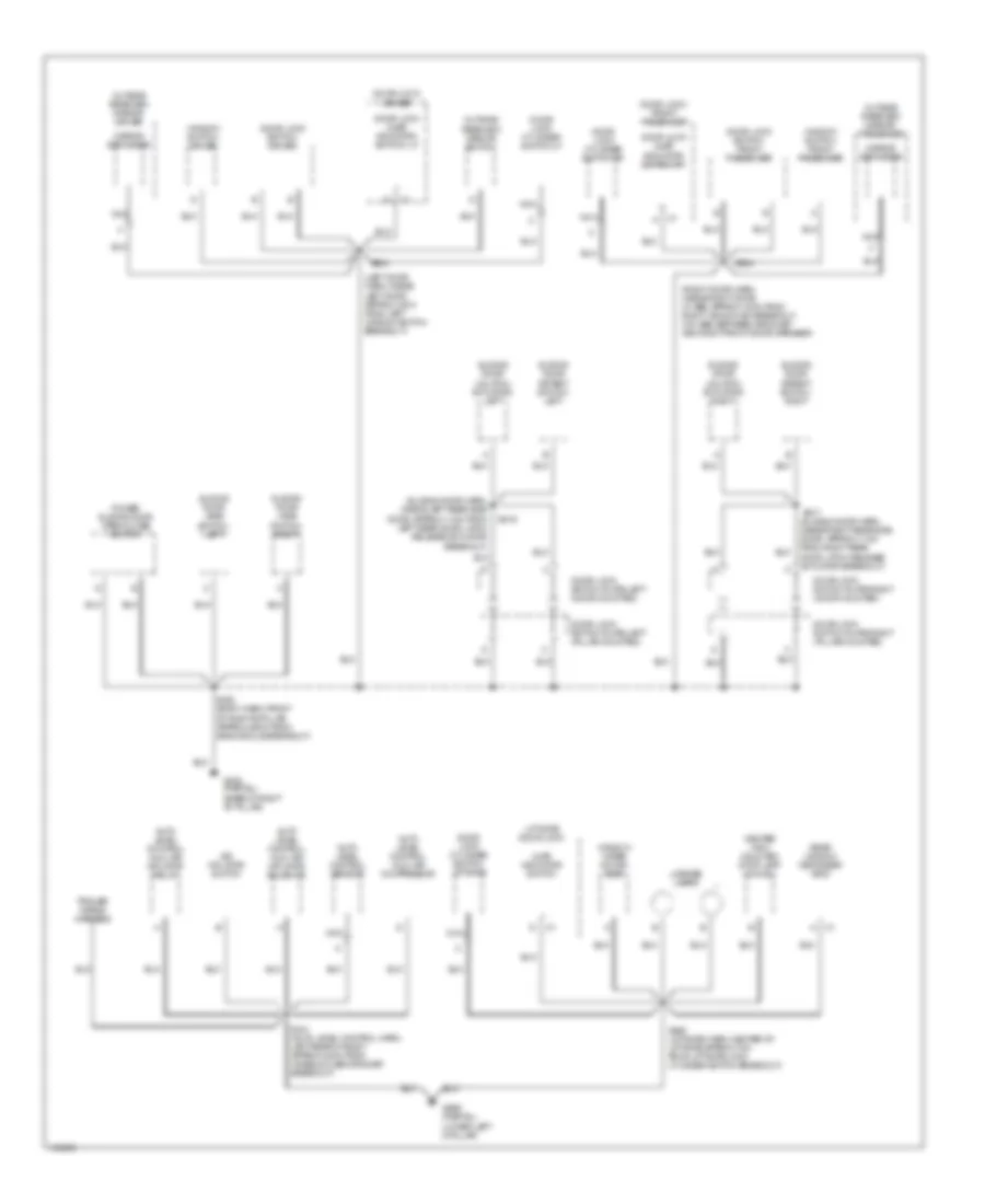
Ground Distribution Wiring Diagram (2 of 3) for Oldsmobile Silhouette GL 2001
List of elements for Ground Distribution Wiring Diagram (2 of 3) for Oldsmobile Silhouette GL 2001:
- (i/p harn, left side of dash approx 15cm from radio breakout)
- (left side of front floor console bracket) g302
- A18
- Air temperature actuator- auxiliary
- Ambient air temperature sensor
- Auxiliary module
- Auxiliary power outlet rear
- Blower motor relay- auxiliary
- Body control module (bcm)
- C1 e
- C313
- C314
- Data link connector (dlc)
- Dome lamp
- Driver information display (dic)
- Driver seat assembly
- Electronic brake control module (ebcm)
- Fuel pump
- Fuel tank
- G133 (engine comartment, near starter solenoid)
- G201 (partial) (right side of dash, left of heater-a/c vent)
- G305 (partial) (base of right b-pillar)
- G308 (lower left "b" pillar)
- G998 (lower right "d" pillar)
- G999 (partial) (lower left d-pillar)
- Hvac control module- rear auxiliary
- Ignition key alarm switch
- Inflatable restraint sensing & diagnostic module (sdm)
- Instrument panel cluster (ipc)
- Interior lamp & multi-function switch assembly
- Interior lamps override switch
- Left backup lamp
- Left rear turn lamp
- Left tail/ stop lamp
- Left taillamp
- Memory seat switch
- Mode actuator auxiliary
- Nca
- Passenger seat assembly
- Power sliding door open/close switch
- Rear object sensor control module
- Rear quarter window switch
- Remote control door lock receiver (rcdlr)
- Right backup lamp
- Right rear turn lamp
- Right tail/ stop lamp
- Right taillamp
- Roof rail reading lamp-lf
- Roof rail reading lamp-lr
- S211
- S280 (i/p harn, right side of dash approx 10cm from right bulkhead grommet)
- S333 (body harn, front of left b-pillar approx 39cm from g308 breakout)
- S390 (roof harn, overhead console approx 10cm from right sunshade lighted vanity mirror breakout)
- S403 (body harn, left rear of body approx 13cm from top and rear clip)
- S406 (body harn, left rear of body approx 17cm from breakout at left taillamp grommet)
- Seat adjuster switch- driver
- Seat adjuster switch- passenger
- Shock sensor
- Sliding door module- left
- Sliding door module- right
- Sliding door open/close switch
- Tan
- Theft deterrent module
- Vanity mirror lamp- left
- Vanity mirror lamp- right
- Vehicle interface unit (viu)
- W/ rear a/c
- W/o rear a/c
- Window washer pump- rear
- Windshield header courtesy/ reading lamps
- Windshield washer fluid pump
- Windshield wiper motor
Ground Distribution Wiring Diagram (3 of 3) for Oldsmobile Silhouette GL 2001
List of elements for Ground Distribution Wiring Diagram (3 of 3) for Oldsmobile Silhouette GL 2001:
- (left door harn, inside left door approx 10cm from left window switch breakout)
- (right door harn, inside right door, w/ abs: approx 10cm from right window sw breakout, w/o abs: between grommet and right front door speaker)
- (sliding door harn, inside left rear side door, approx 11cm from left rear door latch release actuator breakout)
- (sliding door harn, inside right rear side door, approx 11cm from right rear door latch release actuator breakout)
- Air inflator switch
- Ajar indicator switch
- Auto level control (alc) air compressor
- Auto level control (alc) air inflator relay
- Auto level control (alc) air inflator solenoid
- Auto level control sensor
- Center high mounted stop lamp (chmsl)
- Door lock (ajar indicator switch)-lf
- Door lock (ajar indicator switch)-rf
- Door lock cylinder switch- liftgate
- Door lock cylinder switch-lf
- Door lock cylinder switch-rf
- Door lock switch plate-left (door mounted)
- Door lock switch plate-left (pillar mounted)
- Door lock switch plate-right (door mounted)
- Door lock switch plate-right (pillar mounted)
- Door lock switch- driver
- Door lock switch- front passenger
- Door lock- driver
- Door lock- front passenger
- G305 (partial) (base of right "b" pillar)
- G999 (partial) (lower left d-pillar)
- License lamps
- Liftgate door lock
- Mirror defogger
- Nca
- Outside rearview mirror switch
- Outside rearview mirror- driver
- Outside rearview mirror- passenger
- Power sliding door open/close switch
- Rear window defogger grid
- S303 (body harn, front of right b-pillar approx 26cm from srs module breakout)
- S441 (auto level control harn, left rear of body approx 24cm from wheelhouse grommet breakout)
- S460 (liftgate harn, center of liftgate approx 7cm from liftgate lock cylinder switch breakout)
- S504
- S604
- S816
- S817
- Sliding door detent switch- left
- Sliding door detent switch- right
- Sliding door jamb switch- left
- Sliding door jamb switch- right
- Sliding door unlatch actuator- left
- Sliding door unlatch actuator- right
- Trailer wiring harness
- Window switch- driver
- Window switch- front passenger
- Window wiper motor- rear
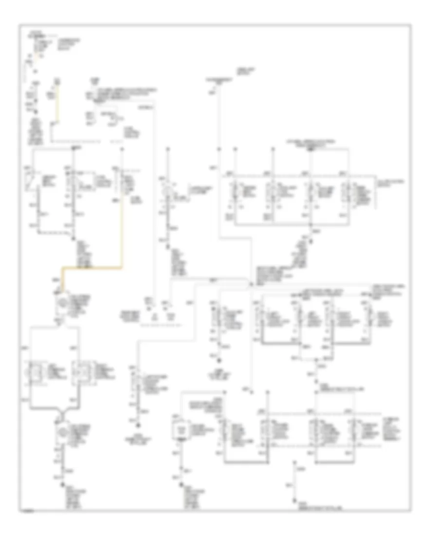
HEADLIGHTS
Headlight Wiring Diagram for Oldsmobile Silhouette GL 2001
List of elements for Headlight Wiring Diagram for Oldsmobile Silhouette GL 2001:
- (i/p harn, 10 cm from radio and rear window wiper/washer multi- function switch breakout) s219
- (i/p harn, approx 10 cm from radio breakout) s204
- Ambient light sensor gnd
- Ambient light sensor in
- Body computer system
- Breakout)
- C1 d
- Daytime running lamps ambient light sensor (top center of dash)
- Daytime running lamps control module (right of steering column)
- Drl fuse 10a
- Drl/hvac/ temp/ htdst fuse 10a
- E10
- E11
- E12
- E13
- Exterior lamps out
- Exterior lights system
- Flash
- Fog lamp relay
- Fog lamp switch
- Fog lp fuse 10a
- Fuse block (right side of dash)
- G101 (right inner fender near battery)
- G108 (right of left headlamp on front upper crossmember)
- G201 (right side of dash, left of heater-a/c vent)
- Gnd
- Head
- Headlamp circuit breaker 20a
- Headlamp dimmer switch
- Headlamp switch
- Headlamps on in
- High
- High beam indicator
- Hot at all times
- Hot in run
- Hot in run, bulb test or start
- Ign (run)
- Ign (run/start)
- Instrument cluster system
- Instrument panel cluster
- L turn sig in
- Left fog lamp
- Left headlamp assembly
- Lf park/turn lamp out
- Low
- Multi-function switch
- Nca
- Off
- On ind
- Park
- Park brake in
- Park brake indicator switch (at left kick panel)
- Park lp fuse 20a
- Pnk
- R turn sig in
- Rf park/turn lamp out
- Right fog lamp
- Right headlamp assembly
- Rke activation input
- S123
- S124
- S212
- S215
- S221 (i/p harn, 4 cm from headlamp switch
- S230
- S264
- Tan
- Underhood junction block
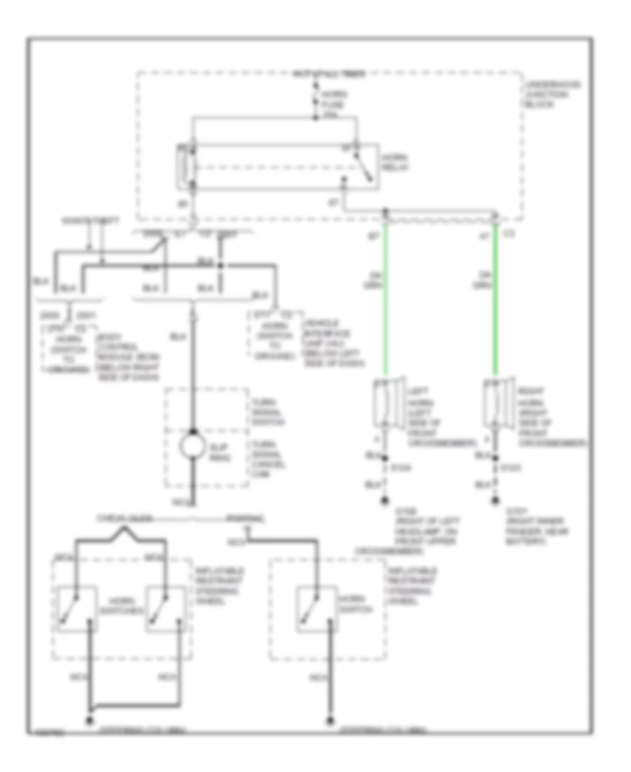
HORN
Horn Wiring Diagram for Oldsmobile Silhouette GL 2001
List of elements for Horn Wiring Diagram for Oldsmobile Silhouette GL 2001:
- (steering column)
- Body control module (bcm) (below right side of dash)
- Chevy, olds
- Crossmember)
- D10
- E11
- G101 (right inner fender, near battery)
- G108 (right of left headlamp, on front upper
- Horn (left side of front crossmember)
- Horn (right side of front crossmember)
- Horn (switch to ground)
- Horn fuse 15a
- Horn relay
- Horn switch
- Horn switches
- Hot at all times
- Inflatable restraint steering wheel
- Left
- Nca
- Pontiac
- Right
- S123
- S124
- Slip ring
- Turn signal cancel cam
- Turn signal switch
- Underhood junction block
- Vehicle interface unit (viu) (below left side of dash)
- W/anti-theft
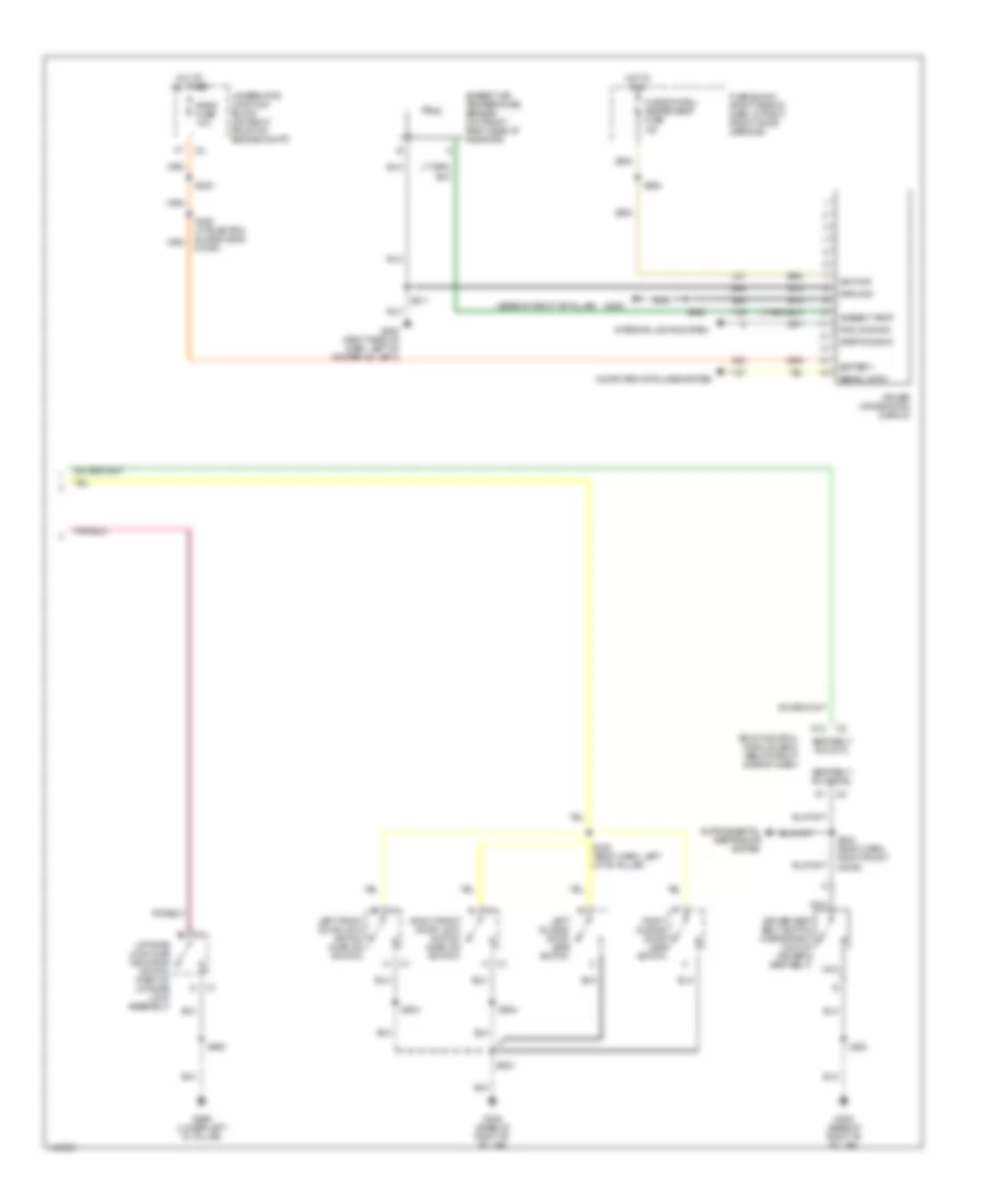
INSTRUMENT CLUSTER
Instrument Cluster Wiring Diagram (1 of 2) for Oldsmobile Silhouette GL 2001
List of elements for Instrument Cluster Wiring Diagram (1 of 2) for Oldsmobile Silhouette GL 2001:
- (class 2)
- (ebtcm)
- (ipc)
- (pcm)
- (thft det)
- A-c1
- A-c2
- Abs ind
- Accy
- Air bag ind
- Aux chime
- B-c1
- Battery
- Body control module (bcm) (below right side of dash)
- Brake fluid level switch (on right side of brake fluid reservoir)
- Brake ind
- C-c1
- C-c2
- Change engine oil
- Charge
- Chime sig
- Cluster batt fuse 10a
- Computer data lines system
- D-c1
- D-c2
- Data line
- Daytime running lights control module
- Door ajar
- E-c1
- E-c2
- Exterior lights system
- F-c1
- F-c2
- Fog lamp ind
- Fuel gauge
- Fuse block (right side of dash, in right front door opening)
- G-c1
- G-c2
- G200 (right side of dash, left of heater-a/c vent)
- G201 (right side of dash, left of heater-a/c vent)
- Ground
- H-c1
- H-c2
- Headlights system
- Headlights system (fog lamp relay)
- High beam ind
- Hot at all times
- Hot coolant temp
- Hot in accy or run
- Hot in run, bulb test or start
- Ign
- Ign 0
- Ign 1
- Ign 1 fuse 10a
- Illumination (4 bulbs)
- Instrument cluster
- Interior lights system
- Internal
- J-c1
- J-c2
- K-c1
- K-c2
- L-c1
- L-c2
- Left turn ind
- Low coolant level
- Low eng oil level
- Low fuel
- Low oil pressure
- M-c1
- M-c2
- Mall/ cluster fuse 10a
- Mil cntl
- Odometer
- Over speed
- Park brake indicator switch (at left kick panel)
- Pcm/passkey/ cluster fuse 10a
- Pnk
- Power distribution system (rap)
- Powertrain control module (bcm) (secured in air cleaner assembly)
- Prndl
- Rap in
- Rear hatch ajar
- Right turn ind
- S209
- S210
- S211
- S230
- S242
- Seat belt ind
- Sec sys warn away ctd disarm
- Security
- Service engine soon ind
- Service traction system
- Speedometer
- Tachometer (olds/pontiac only)
- Temperature gauge
- Trac off ind
- Traction active
- Trailer towing ind
- Trip
- Trip reset
Instrument Cluster Wiring Diagram (2 of 2) for Oldsmobile Silhouette GL 2001
List of elements for Instrument Cluster Wiring Diagram (2 of 2) for Oldsmobile Silhouette GL 2001:
- (base of right "b" pillar)
- Ambient air temperature sensor (on front right side of radiator)
- Ambient temp
- Battery
- Body control module (bcm) (below right side of dash)
- Computer data lines system
- D12
- Driver information display
- Driver seat belt switch (inside right half of driver's seat belt)
- Fuse block (right side of dash, in right front door opening)
- G200 (right side of dash, left of heater-a/c vent)
- G305
- G305 (base of right "b" pillar)
- G999 (lower left "d" pillar)
- Ground
- Hot at all times
- Hot in run
- Hvac/dic/drl/ heated seat fuse 10a
- Ignition
- Interior lights system
- Left front door lock switch (ajar ind switch)
- Left sliding door jamb switch
- Liftgate lock ajar indicator switch (part of liftgate lock assembly)
- Nca
- Pwm dimming
- Radio fuse 10a
- Right front door lock switch (ajar ind switch)
- Right sliding door jamb switch
- S202
- S211
- S264
- S303
- S304 (body harn, right front door)
- S326 (w/ electric sliding side door)
- S330 (body harn, left of "b" pillar)
- S390
- S460
- S504
- S604
- Seat belt ind cntl
- Seat belt sw signal
- Serial data
- Step dimming
- Underhood junction block (on right front of engine compt)
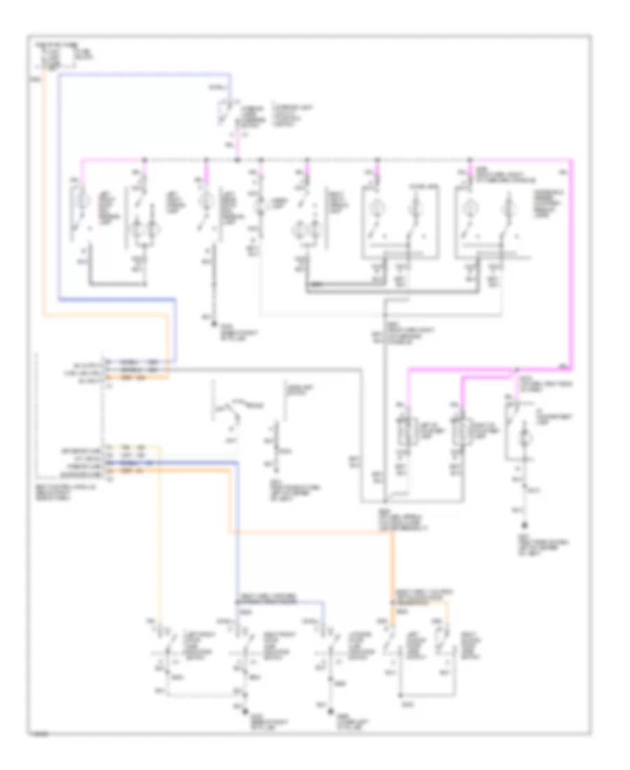
INTERIOR LIGHTS
Courtesy Lamps Wiring Diagram for Oldsmobile Silhouette GL 2001
List of elements for Courtesy Lamps Wiring Diagram for Oldsmobile Silhouette GL 2001:
- (body harn, 7 cm from left sliding door jamb switch)
- (body harn, forward of right front door)
- A nca
- B+ input
- B+ output
- Body control module (below right side of dash)
- Cargo lamp
- Ctsy lamp fuse 10a
- Ctsy lps ctrl
- Dome
- Dome lamp
- Driver dr ajar
- Fuse block
- G201 (right side of dash, left of heater- a/c vent)
- G305 (base of right "b" pillar)
- G999 (lower left "d" pillar)
- Headlamp switch
- Hot at all times
- I/p compartment lamp
- Int lps on
- Interior lamp & multi- function switch
- Interior lamps override switch
- Left front door ajar indicator switch
- Left front roof rail reading lamp
- Left i/p courtesy lamp
- Left rear roof rail reading lamp
- Left sliding door jamb switch
- Left vanity mirror lamp
- Liftgate door ajar indicator switch
- Nca
- Nca b
- Nca c
- Off
- Pass dr ajar
- Right front door ajar indicator switch
- Right i/p courtesy lamp
- Right sliding door jamb switch
- Right vanity mirror lamp
- S213
- S242
- S259 (i/p harn, approx 3 cm from cigar lighter breakout)
- S272 (i/p harn, right side of dash)
- S303
- S309
- S325
- S390
- S393 (roof harn, right of overhead console)
- S397 (roof harn, right of overhead console)
- S460
- S504
- S604
- Sliding dr ajar
- Tan
- Windshield header courtesy/ reading lamps
Instrument Illumination Wiring Diagram for Oldsmobile Silhouette GL 2001
List of elements for Instrument Illumination Wiring Diagram for Oldsmobile Silhouette GL 2001:
- (4 bulbs)
- (6 bulbs)
- (body harn, approx 33 cm forward of right door lock switch plate) s320
- (i/p harn, approx 6 cm from radio & rear wiper multifunction switch breakout) s223
- (i/p harn, approx 9 cm from radio breakout) s203
- (left door harn, 35 cm from window switch) s506
- (right door harn, 35 cm from window switch) s606
- Auxiliary blower switch
- Auxiliary rear hvac control module
- B12
- Dc dim
- Driver information display
- Foglamp/ tcs switch
- Fuse block
- G201 (right side of dash, left of heater- a/c vent)
- G305 (base of right "b" pillar)
- G999 (lower left "d" pillar)
- Gnd
- Headlamp switch
- Heated seat switch
- Hot at all times
- Hvac control module
- Incandescent dim
- Inflatable restraint steering wheel module coil
- Instrument cluster
- Interior lamp & multi- function switch assembly
- Interior lamps override switch
- Left front door lock switch
- Left front window switch
- Left power sliding door open/close switch
- Left steering wheel controls
- Memory seat switch
- Multifunction switch
- Nca
- Park lp fuse 20a
- Power sliding door switch
- Pwm dim
- Radio
- Rear power quarter window switch
- Rear seat audio (rsa) control
- Rear window wiper/ washer switch
- Right front door lock switch
- Right front window switch
- Right power sliding door open/close switch
- Right steering wheel controls
- S211
- S213
- S230
- S242
- S303
- S390
- S395 (roof harn, right side of overhead console)
- S403
- S504
- S604
- Step dim
- Swc back- light fuse 2a
- Underhood junction block
- Vf dim
MEMORY SYSTEMS
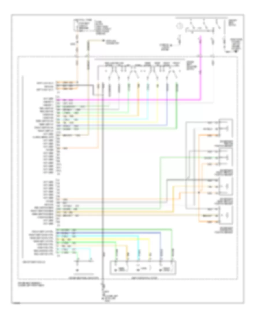
Driver's Memory Seat Wiring Diagram for Oldsmobile Silhouette GL 2001
List of elements for Driver's Memory Seat Wiring Diagram for Oldsmobile Silhouette GL 2001:
- (lower left "b" pillar) g308
- (right side of dash, left of heater- a/c vent) g201
- 30a
- A10
- A11
- A12
- Aft
- B10
- B11
- B12
- Batt (high volt)
- Batt (low volt)
- Class 2 serial data
- Data link connector
- Driver seat adjuster switch
- Driver seat assembly (under left front seat)
- Driver seat front verticle position sensor
- Driver seat horiizontal position sensor
- Driver seat rear verticle position sensor
- Driver seat recline motor
- Driver seat recline position sensor
- Fore
- Front down
- Front up
- Front up-dn
- Front vert down
- Front vert down ctrl
- Front vert pos sens
- Front vert up
- Front vert up ctrl
- Fuse block (right side dash, in right front door opening)
- Ground
- Horz
- Horz fwd
- Horz fwd ctrl
- Horz pos sens
- Horz rwd
- Horz rwd ctrl
- Hot at all times
- Interior lights system
- Memory 1
- Memory 2
- Memory seat module
- Memory seat switch
- Not used
- Power
- Pwr seat circuit breaker
- Rear down
- Rear up
- Rear up-dn
- Rear vert down
- Rear vert down ctrl
- Rear vert pos sens
- Rear vert up
- Rear vert up ctrl
- Recline down
- Recline fwd
- Recline fwd ctrl
- Recline pos sens
- Recline rwd
- Recline rwd ctrl
- Recline up
- S302
- S333
- Seat horizontal motor
- Tan
NAVIGATION
Parking Assistant Wiring Diagram for Oldsmobile Silhouette GL 2001
List of elements for Parking Assistant Wiring Diagram for Oldsmobile Silhouette GL 2001:
- B/u lamp fuse 10a
- Backup lamp voltage
- Body control module (below right side of dash)
- Diagnostic input
- Engine controls system
- Exterior lights system
- Fuse block
- G305 (base of right b-pillar)
- G999 (lower left d-pillar)
- Ground
- Hot at all times
- Hot in run or start
- Ign 1 fuse 10a
- Instrument panel cluster
- Interior lamp and multi-function switch assembly
- Left rear corner object sensor (in left corner of rear bumper)
- Left rear middle object sensor (in left middle of rear bumper)
- Low ref
- Lr corner sensor sig
- Lr middle sensor sig
- Pnk
- Rear object sensor control module (behind trim panel at right front of cargo area)
- Rear park chime sig
- Rear parking assist diagnostic connector
- Rear parking assist display
- Rear quarter window switch
- Red
- Red ind ctrl
- Red indicator
- Right rear corner object sensor (in right corner of rear bumper)
- Right rear middle object sensor (in right middle of rear bumper)
- Rr corner sensor sig
- Rr middle sensor sig
- S337
- S390
- S406
- S428
- S429 (parking aid sensor harn, near middle right parking aid sensor)
- S435
- Sensor low ref
- Sensor signal
- Sensor voltage
- Sw sig in
- Telltail assy voltage
- Transmission range switch
- Underhood accessory wiring junction block
- Vss signal
POWER DISTRIBUTION
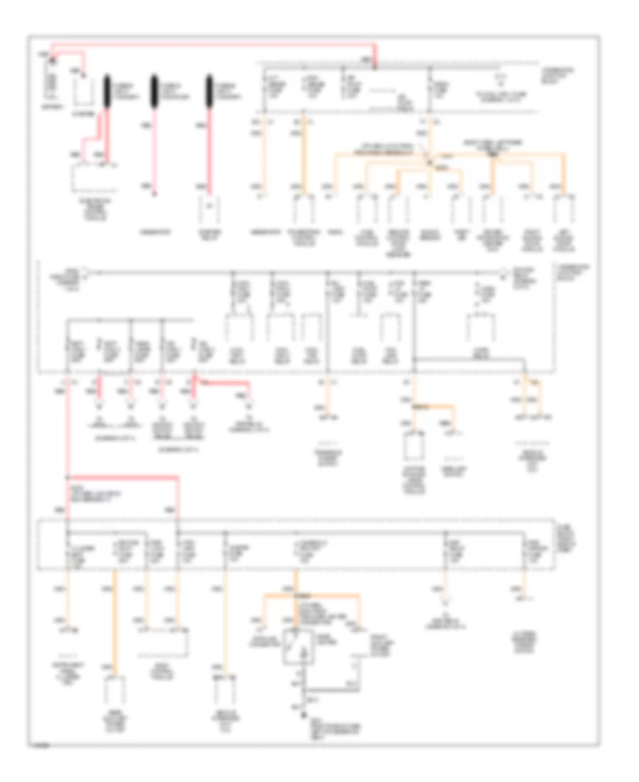
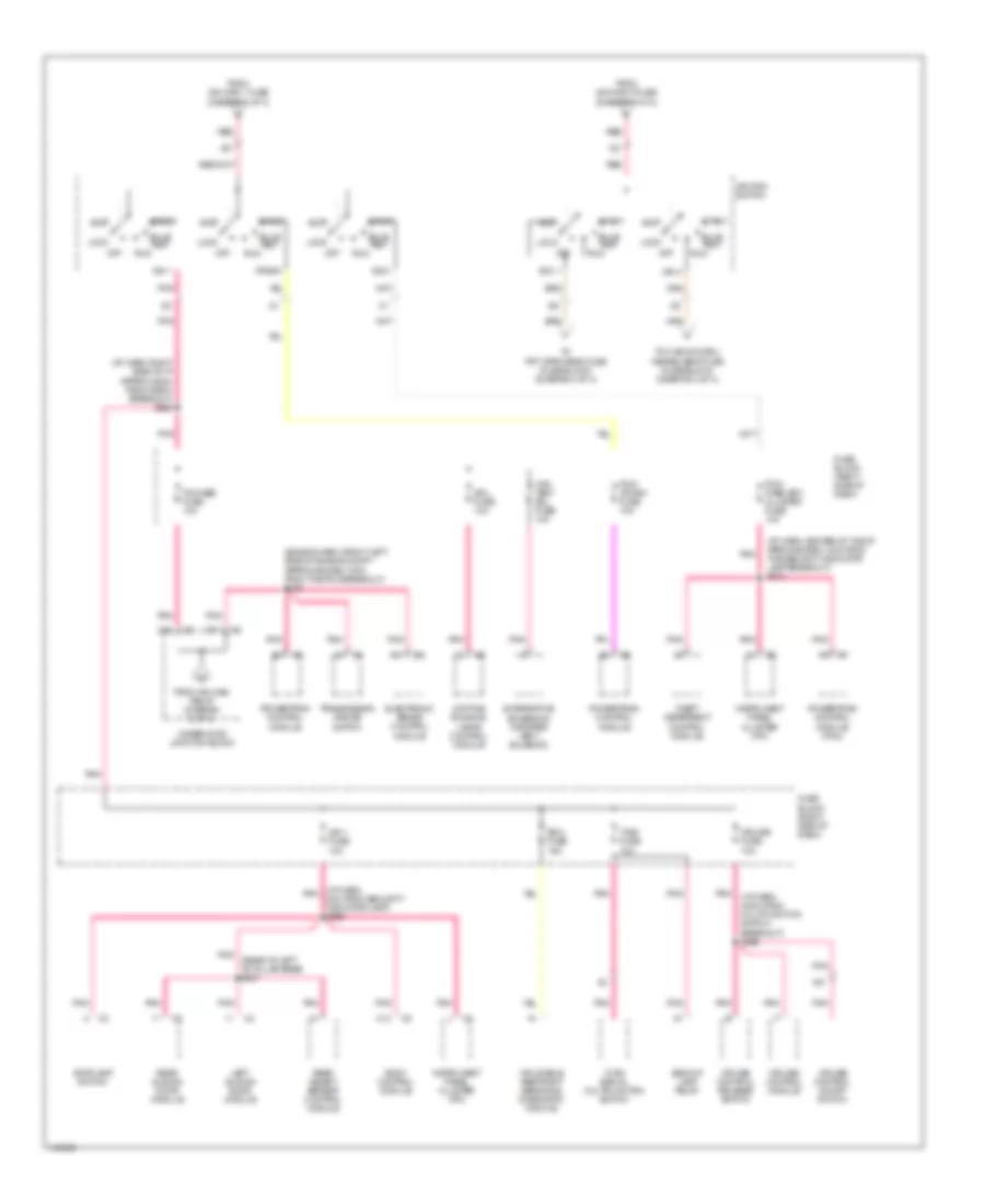
Power Distribution Wiring Diagram (1 of 4) for Oldsmobile Silhouette GL 2001
List of elements for Power Distribution Wiring Diagram (1 of 4) for Oldsmobile Silhouette GL 2001:
- (body harn, left rear wheelwell) s326
- (diagram 1 of 4)
- (diagram 2 of 4)
- (diagram 3 of 4)
- (i/p harn, 21cm from from radio breakout)
- (i/p harn, 80cm from the cigar lighter connector)
- Air pump fuse 30a
- Air pump relay
- Alt/ sense fuse 10a
- B/u lamp fuse 10a
- Batt main 1 fuse 60a
- Batt main 2 fuse 60a
- Battery
- Body control module
- Cigar lighter
- Cigar/dlc/ apo frt fuse 15a
- Cluster batt fuse 10a
- Cool fan 1 fuse 30a
- Cool fan 1 relay
- Cool fan 2 fuse 30a
- Cool fan 2 relay
- Cool fan relay
- Ctsy lamp fuse 10a
- Data link connector
- Daytime running lamps control module
- Driver information center (dic)
- E12
- E16
- Ecm sense fuse 10a
- Electronic brake control module
- Fog lamp relay
- Fog lp fuse 10a
- From radio fuse a
- Front auxiliary power outlet
- Fuel pump fuse 15a
- Fuel pump relay
- Fuse block (right side of dash)
- Fusible link a (10ga-rust)
- G201 (right side of dash, left of heater-a/c vent)
- Generator
- Head- lamps fuse 60a
- Headlamp switch
- Horn fuse 15a
- Horn relay
- Hvac control module
- Ign main 1 fuse 40a
- Ign main 2 fuse 60a
- Ign main relay (diagram 2 of 4)
- Instrument panel cluster (ipc)
- Left sliding door module
- Onstar fuse 10a
- Outside rearview mirror switch
- Park lp fuse 20a
- Powertrain control module
- Pwr lock fuse 20a
- Pwr mirror fuse 10a
- Radio
- Radio fuse 10a
- Rap relay fuse 10a
- Rear auxiliary power outlet
- Red
- Remote control door lock receiver
- Right sliding door module
- Rr pwr sckt fuse 20a
- S202
- S212
- S213
- S238
- S276 (i/p harn, 8cm from bcm breakout)
- Shock sensor
- Starter
- Starter relay
- Theft led
- To cool fan 1 fuse (diagram 1 of 4)
- To ignition switch pin d2
- To ignition switch pin d5
- To rap relay (diagram 4 of 4)
- To s274
- To s278
- Transaxle range switch
- Underhood junction block
- Vehicle interface unit (viu)
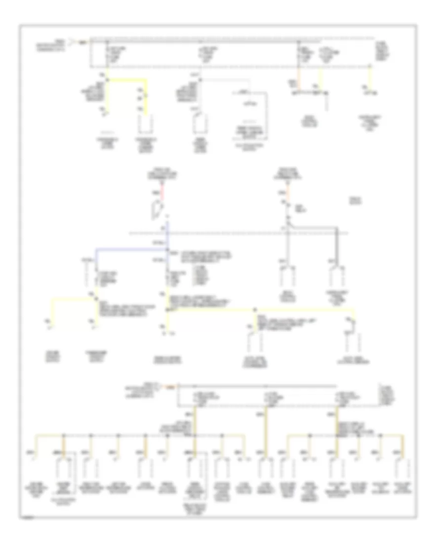
Power Distribution Wiring Diagram (2 of 4) for Oldsmobile Silhouette GL 2001
List of elements for Power Distribution Wiring Diagram (2 of 4) for Oldsmobile Silhouette GL 2001:
- (6 cm from relay block breakout) s270
- (behind left rear trim panel) s322
- (body harn, 34cm from inflatable restraint sensing & diagnostic module) s302
- (diagram 1 of 4)
- (fuel inj harn, center of engine) s109
- (i/p harn, 13 cm from headlamp switch breakout) s215
- A/c clu fuse 10a
- A/c clu relay
- A12
- Air injection bleed valve
- Air pump relay
- Auto level control air compressor
- Auto level control air inflator relay
- Auto level control sensor
- Automatic transmission
- Blower motor resistor assembly
- C111
- Ctrl sols
- Daytime running lamps control module
- Driver seat assembly
- Elc/trailer fuse 25a
- Elek ign fuse 15a
- Evaporative emissions canister purge solenoid
- From batt main 2 fuse
- From headlamps fuse
- From horn fuse (underhood junction block) (hot at all times) (diagram 1 of 4)
- Frt hvac hi blowr circuit breaker 30a
- Fuel injector
- Fuse block (right side of dash)
- G110 (left of starter)
- Hazard fuse 15a
- Headlamp circuit breaker 20a
- Headlamp dimmer switch
- Headlamp switch
- Heated oxygen sensor
- Ign i- u/h fuse 15a
- Ign main relay
- Ignition control module
- Inj fuse 10a
- Left sliding door module
- Mass air flow sensor
- Nca
- Pass key fuse 10a
- Passenger seat assembly
- Pnk
- Pwr seat/ psd circuit breaker 30a
- Pwr sldg dr fuse 30a
- Rear fog lamp relay
- Rear window defogger relay
- Red
- Relay block
- Right sliding door module
- Rr defog fuse 30a
- Rr fog lp fuse 30a
- S106
- S274 (i/p harn, 4cm from bcm breakout)
- S278 (i/p harn, 12cm from bcm breakout)
- S445 (auto level control harn, left rear of body approx 16cm from left rear wheelhouse grommet)
- Stop lamp fuse 15a
- Stop- lamp switch
- Stoplamp switch
- Tcc fuse 10a
- Theft deterrent control module
- To pcm fuse (fuse block) (hot in run, bulb test or start) (diagram 3 of 4)
- Trailer wiring harness
- Turn/signal multifunction switch
- Underhood junction block
Power Distribution Wiring Diagram (3 of 4) for Oldsmobile Silhouette GL 2001
List of elements for Power Distribution Wiring Diagram (3 of 4) for Oldsmobile Silhouette GL 2001:
- (engine harn, front left side of engine compt approxiamately 8cm from the pcm breakout) s108
- (i/p harn, 24cm from multifunction switch breakout) s266
- (i/p harn, center of the i/p aproxiamately 4cm from the security indicator lamp breakout) s210
- (i/p harn, pnk 8cm from security indicator lamp) s209
- (i/p harn, right side of i/p approx 25cm from radio breakout) s228
- (rear of left "b" pillar base) s337
- A11
- A13
- Acc
- Acc 1
- Backup lamp relay
- Body control module
- Bulb test
- C10
- C13
- Can vent sol fuse 10a
- Crank
- Cruise control module
- Cruise control on/off switch
- Cruise control release switch
- Cruise fuse 10a
- D11
- Daytime running lamps control module
- Drl fuse 10a
- Electronic brake control module
- Evaporative emissions canister vent solenoid
- From ign main 1 fuse (diagram 1 of 4)
- From ign main 2 fuse (diagram 1 of 4)
- From ign main relay (diagram 2 of 4)
- Fuse block (right side of dash)
- Ign 0
- Ign 1
- Ign 1 fuse 10a
- Ign 3
- Ignition switch
- Inflatable restraint sensing & diagnostic module
- Instrument panel cluster (ipc)
- Left sliding door module
- Lock
- Off
- Pcm/ crank fuse 10a
- Pcm/ pass key/ cluster fuse 10a
- Pcm/abs fuse 10a
- Pnk
- Powertrain control module
- Powertrain control module (pcm)
- Rear object sensor control module
- Rear sliding door module
- Red
- Run
- Sdm fuse 15a
- Start
- Stoplamp switch
- T/sig fuse 10a
- Theft deterrent control module
- To frt wpr/wshr fuse (fuse block) (diagram 4 of 4)
- To hvac/dic/drl/ heated seat fuse (fuse block) (diagram 4 of 4)
- Transmission range switch
- Turn signal/ multifunction switch
- Underhood junction block
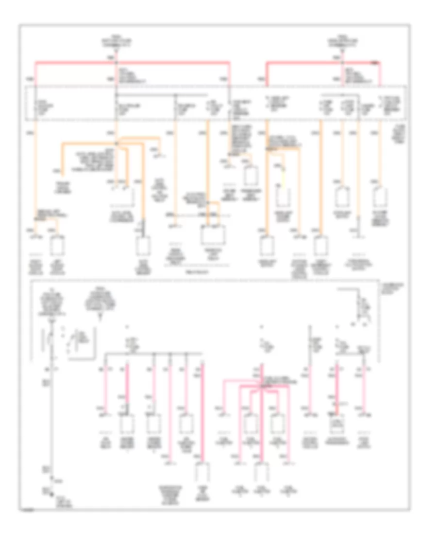
Power Distribution Wiring Diagram (4 of 4) for Oldsmobile Silhouette GL 2001
List of elements for Power Distribution Wiring Diagram (4 of 4) for Oldsmobile Silhouette GL 2001:
- (body harn, in front of left rear wheelhouse) s345
- (body harn, under right front door sill, approxiamately 17cm from harness breakout) s317
- (diagram 3 of 4)
- (i/p harn, 16cm from relay block breakout) s264
- (i/p harn, right side of the i/p at the electric air inlet actuator breakout)
- Auto level control air compressor
- Auto level control sensor
- Auxiliary air temperature actuator
- Auxiliary blower motor
- Auxiliary blower motor relay
- Auxiliary mode actuator
- Auxiliary txv solenoid
- Bcm prgrm fuse 10a
- Body control module
- Daytime running lamps control module
- Driver information center (dic)
- Driver window switch
- Drl/hvac/ temp/htd st fuse 10a
- From ign main 2 maxi fuse (diagram 1 of 4)
- From ignition switch
- From ignition switch j (hot in run) (diagram 3 of 4)
- From rap relay fuse (diagram 1 of 4)
- Frt wpr/ wshr fuse 25a
- Fuse block (right side of dash)
- Heated seat switch
- Hvac blower fuse 25a
- Hvac control assembly
- Hvac control module
- Instrument panel cluster (ipc)
- Left air temperature actuator
- Mall/ cluster fuse 10a
- Mode actuator
- Multifunction switch
- Multifuntion switch
- Nca
- Passenger window switch
- Pwr otr vent fuse 10a
- Pwr wdo circuit breaker 30a
- Rap relay
- Rear auxiliary hvac control assembly
- Rear quarter window switch
- Rear window defogger relay
- Rear window wiper motor
- Rear window wiper/ washer switch
- Recir- culation actuator
- Red
- Relay block
- Relay block (right side of dash)
- Right air temperature actuator
- Rr hvac/ te;mp cont fuse 25a
- Rr wpr/ wshr fuse 20a
- S245 (i/p harn, approx 5cm from radio breakout)
- S249 (i/p harn, approx 14cm bulkhead grommet)
- S263
- S307 (boyd harn, right front door approxiamately 4cm from the door harn breakout)
- S440 (auto level control harn, left rear of the body behind left wheelhouse)
- Windshield wiper motor
- Windshield wiper/ washer switch
POWER DOOR LOCKS
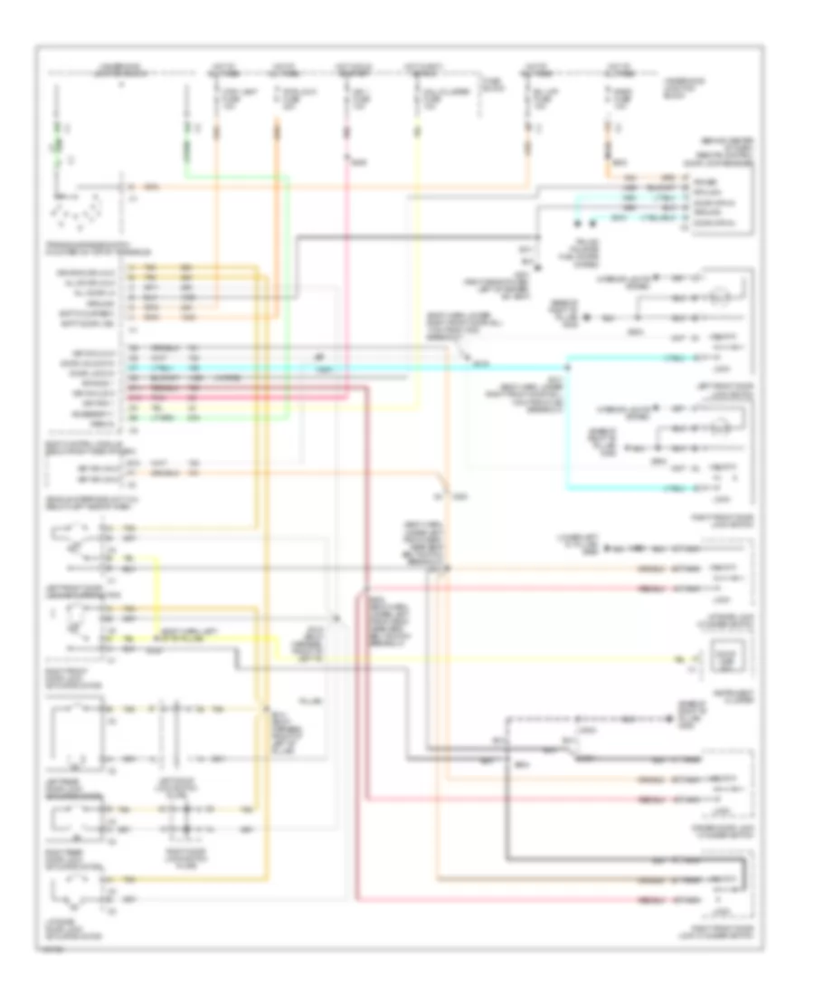
Power Door Lock Wiring Diagram for Oldsmobile Silhouette GL 2001
List of elements for Power Door Lock Wiring Diagram for Oldsmobile Silhouette GL 2001:
- (base of right "b" pillar) g305
- (behind center of dash) remote control door lock receiver
- (body harn, left of "b" pillar)
- (body harn, under left front seat, near seat belt switch breakout) s327
- (body harn, under right front door sill 17cm from c302 breakout)
- (lower left "d" pillar) g999
- (w/ rke)
- Accessory 1
- All door lk
- All door unlk
- B/u lmp fuse 10a
- Batt (courtesy)
- Batt (door lks)
- Body control module (below right side of dash)
- C11
- C13
- C200
- Ctsy lamp fuse 10a
- Door ajar ind
- Door lock in
- Door opn in
- Door unlock in
- Driver door lock cylinder switch
- Drivr door unlk
- E12
- Fuse block
- G201 (right side of dash, left of heater- a/c vent)
- Ground
- Hot at all times
- Hot in accy or run
- Hot in run or start
- Ign 1 fuse 10a
- Ignition 1
- Instrument cluster
- Interior lights system
- Key sw lock
- Key sw unlk
- Left door lock switch plate
- Left front door lock actuator motor
- Left front door lock switch
- Left rear door lock actuator motor
- Liftgate door lock actuator motor
- Liftgate lock cylinder switch
- Lock
- Mall/cluster fuse 10a
- Nca
- Park in
- Pillar)
- Pnk
- Power
- Pwr lock fuse 20a
- Radio fuse 10a
- Rfa cmd 1
- Rfa link
- Right door lock switch plate
- Right front door lock actuator motor
- Right front door lock cylinder switch
- Right front door lock switch
- Right rear door lock actuator motor
- S202
- S209
- S211
- S303
- S311 (body harn, under right front door sill, 13cm from c302 breakout)
- S314 (body harness, front of left "b" pillar)
- S315 (body harness, front of left "b"
- S319
- S323 (body harn, under left front seat, near seat belt switch breakout)
- S330
- S460
- S504
- S604
- Tan
- Transaxle range switch (mounted on top of transaxle)
- Trunk/ tailgate/ fuel doors system
- Underhood junction block
- Unlock
- Vehicle interface unit (viu) (below left side of dash)
POWER MIRRORS
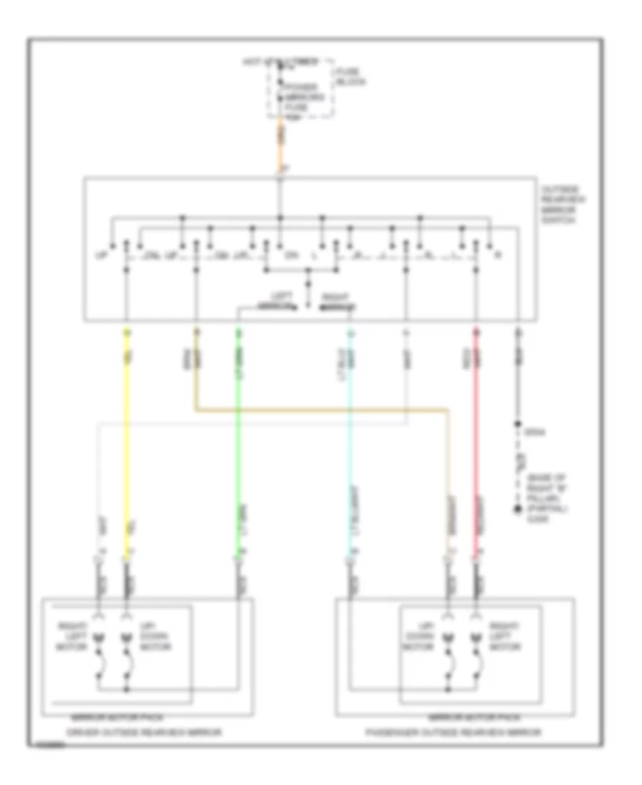
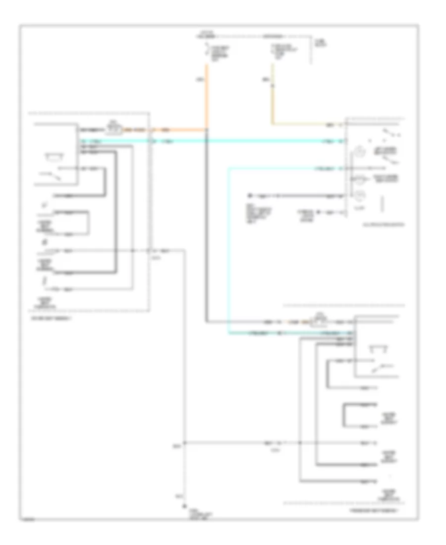
Power Mirror Wiring Diagram for Oldsmobile Silhouette GL 2001
List of elements for Power Mirror Wiring Diagram for Oldsmobile Silhouette GL 2001:
- (base of right "b" pillar) (partial) g305
- Driver outside rearview mirror
- Fuse block
- Hot at all times
- Left mirror
- Mirror motor pack
- Nca
- Outside rearview mirror switch
- Passenger outside rearview mirror
- Power mirrors fuse 10a
- Right mirror
- Right/ left motor
- S504
- Up/ down motor
POWER SEATS
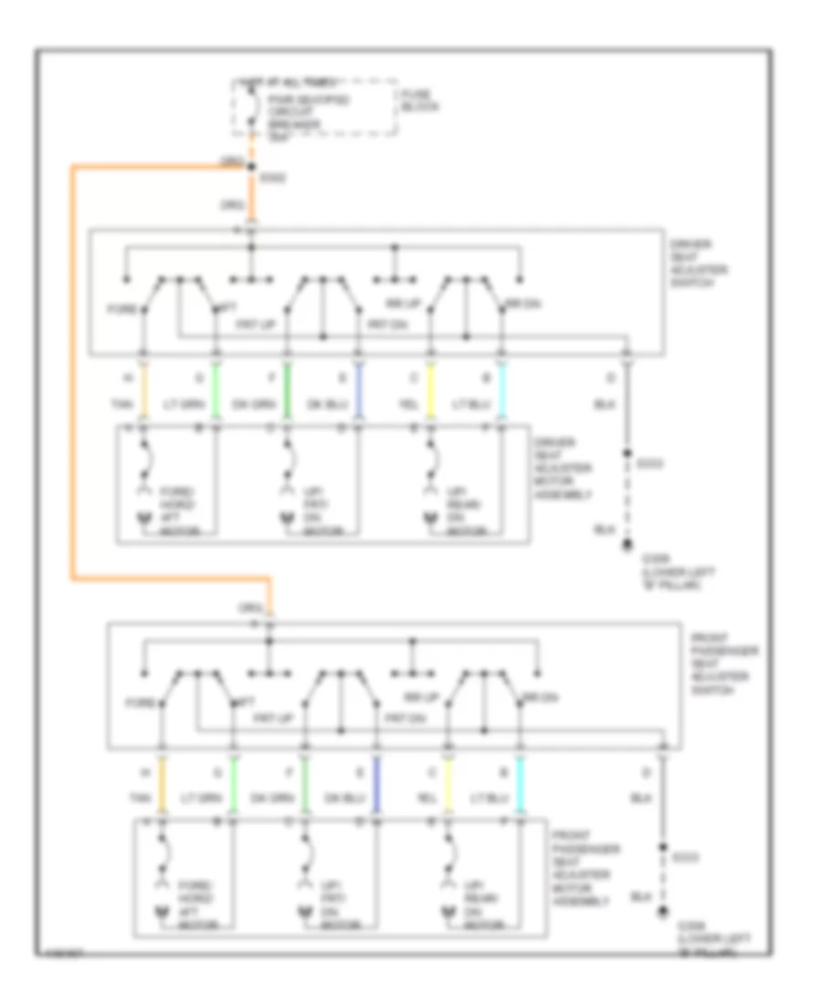
6-Way Power Seat Wiring Diagram for Oldsmobile Silhouette GL 2001
List of elements for 6-Way Power Seat Wiring Diagram for Oldsmobile Silhouette GL 2001:
- Aft
- Driver seat adjuster motor assembly
- Driver seat adjuster switch
- Fore
- Fore/ horz/ aft motor
- Front passenger seat adjuster motor assembly
- Front passenger seat adjuster switch
- Frt dn
- Frt up
- Fuse block
- G308 (lower left "b" pillar)
- Hot at all times
- Pwr seat/psd circuit breaker 30a
- Rr dn
- Rr up
- S302
- S333
- Tan
- Up/ frt/ dn motor
- Up/ rear/ dn motor
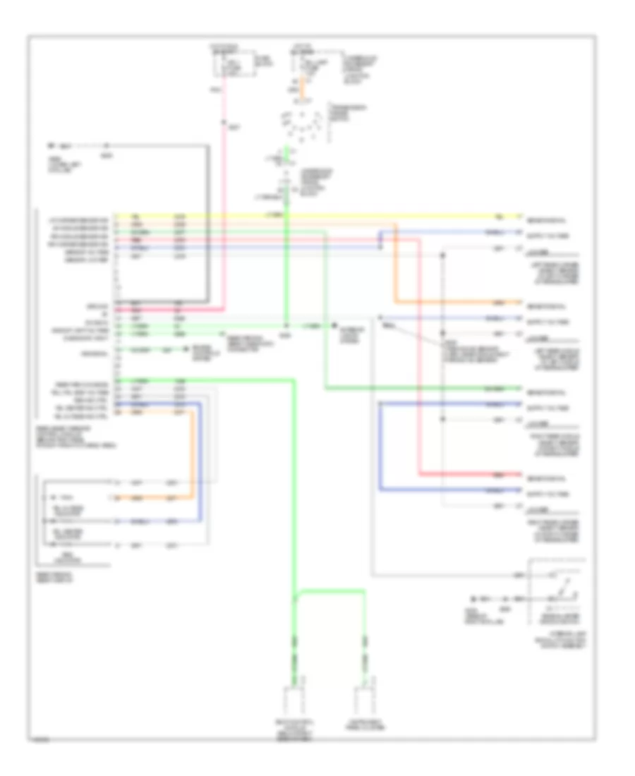
Heated Seats Wiring Diagram for Oldsmobile Silhouette GL 2001
List of elements for Heated Seats Wiring Diagram for Oldsmobile Silhouette GL 2001:
- C313
- C314
- Driver seat assembly
- Drl/hvac temp/htd st fuse 10a
- Fuse block
- G201 (right side of dash, left of heater-a/c vent)
- G308 (lower left "b" pillar)
- Heated seat element
- Heated seat thermistor
- Hot at all times
- Hot in run
- Illum
- Interior lights system
- Left heated seat switch
- Multifunction switch
- Nca
- Passenger seat assembly
- Ptc device
- Pwr seat circuit breaker 30a
- Right heated seat switch
- S333
POWER WINDOWS
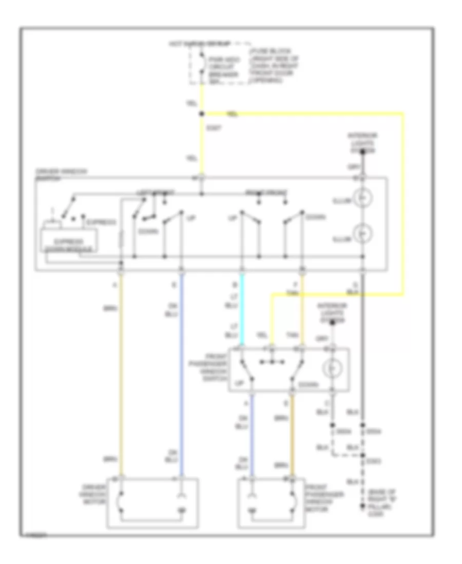
Power Windows Wiring Diagram for Oldsmobile Silhouette GL 2001
List of elements for Power Windows Wiring Diagram for Oldsmobile Silhouette GL 2001:
- (base of right "b" pillar) g305
- Down
- Driver window motor
- Driver window switch
- Express
- Express down module
- Front passenger window motor
- Front passenger window switch
- Fuse block (right side of dash, in right front door opening)
- Hot in run or rap
- Illum
- Interior lights system
- Left front
- Pwr wdo circuit breaker 30a
- Right front
- S303
- S307
- S504
- S604
- Tan
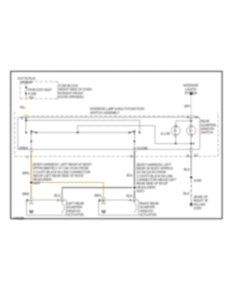
Rear Quarter Windows Wiring Diagram for Oldsmobile Silhouette GL 2001
List of elements for Rear Quarter Windows Wiring Diagram for Oldsmobile Silhouette GL 2001:
- (base of right "b" pillar) g305
- (body harness, left rear of body approx. 54 cm (20 in) from 3 cavity black in-line connector above left rear side of roof headliner) s423
- Above left rear side of roof headliner) s427
- Close
- Fuse block (right side of dash, in right front door opening)
- Hot in run or rap
- Illum
- Interior lamp & multi-function switch assembly
- Interior lights system
- Left rear quarter window actuator
- Open
- Pwr qtr vent fuse 10a
- Rear quarter window switch
- Right rear quarter window actuator
- S390
RADIO
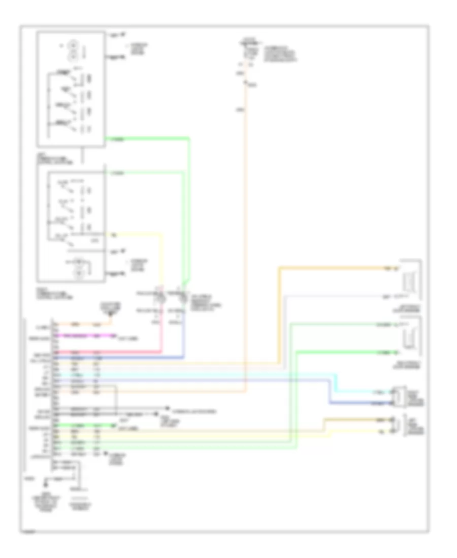
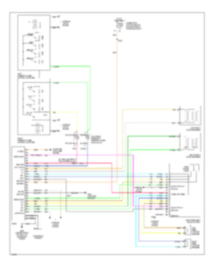
Radio Wiring Diagrams, Base Radio for Oldsmobile Silhouette GL 2001
List of elements for Radio Wiring Diagrams, Base Radio for Oldsmobile Silhouette GL 2001:
- A10
- A11
- A12
- Am/fm
- B10
- B11
- B12
- Battery
- Class 2
- Computer data lines system
- D6 (not used)
- Dim sig
- E8 (not used)
- G202 (left side of dash)
- G909 (center front of roof, on windshield frame)
- Ground
- Hot at all times
- Inflatable restraint steering wheel module coil
- Interior lights system
- Left front door speaker
- Left rear liftgate speaker
- Left steering wheel control switches
- Lf +
- Lf -
- Lmps on in
- Lr +
- Lr -
- Mute
- Nca
- Play
- Pnk
- Preset
- Radio
- Radio fuse 10a
- Rear audio
- Ref pwr
- Rf +
- Rf -
- Right front door speaker
- Right rear liftgate speaker
- Right steering wheel control switches
- Rr +
- Rr -
- S202
- S247
- Seek dn
- Seek up
- Tan
- Underhood junction block (on right front of engine compt)
- Vol dn
- Vol up
- Whl ctrls
- Windshield antenna
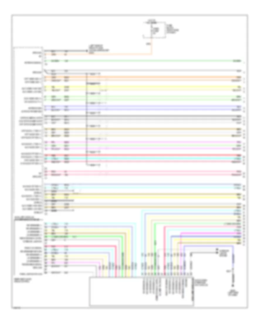
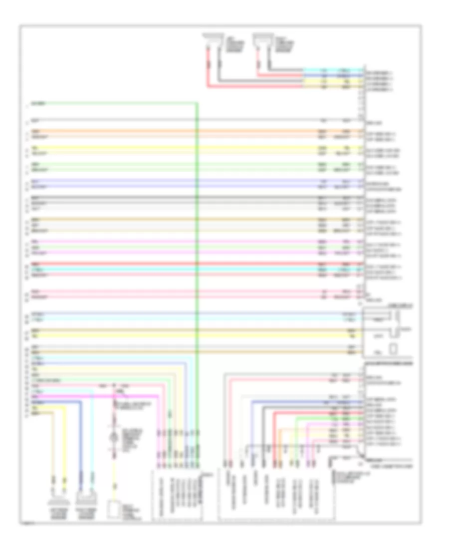
Radio Wiring Diagrams, Premium Radio for Oldsmobile Silhouette GL 2001
List of elements for Radio Wiring Diagrams, Premium Radio for Oldsmobile Silhouette GL 2001:
- (i/p harn, center of the i/p approx 8 cm) s225
- A10
- A11
- A12
- Am/fm
- Audio ctrl in
- Audio ctrl out
- B10
- B11
- B12
- Battery
- Class 2
- Computer data lines system
- Dim sig
- Fused acc feed
- G202 (left side of dash)
- G909 (center front of roof, on windshield frame)
- Ground
- Head phone jacks
- Hot at all times
- Inflatable restraint steering wheel module coil
- Interior lights system
- Left front door speakers
- Left rear liftgate speaker
- Left steering wheel control switches
- Lf +
- Lf -
- Lmps on in
- Lr +
- Lr -
- Mute
- Nca
- Play
- Pnk
- Preset
- Pwm dim
- Radio
- Radio fuse 10a
- Radio rear seat audio control
- Rear audio
- Ref pwr
- Rf +
- Rf -
- Right front door speakers
- Right rear liftgate speaker
- Right steering wheel control switches
- Rr +
- Rr -
- S202
- S247
- Seek dn
- Seek up
- Step dim
- Tan
- Underhood junction block (on right front of engine compt)
- Vol dn
- Vol up
- Whl ctrls
- Windshield antenna
Video System Wiring Diagram (1 of 2) for Oldsmobile Silhouette GL 2001
List of elements for Video System Wiring Diagram (1 of 2) for Oldsmobile Silhouette GL 2001:
- (left side of front floor console bracket) g302
- Antenna sig
- Antenna signal
- Audio/video interface (avi) module
- Aux audi rt sig (+)
- Aux audi sig (-)
- Aux audio lt sig (+)
- Aux audio rt sig (+)
- Aux audio sig (-)
- Aux video high sig
- Aux video low sig
- Auxillary module (in overhead console)
- Bare
- Dvd audio lt sig (+)
- Dvd audio rt sig (+)
- Dvd audio sig (-)
- Dvd status ser data
- Dvd video sig (+)
- Fuse block (right side of dash)
- G202 (left side of dash)
- Ground
- Hot at all times
- I/l lamp voltage
- Interior lamp dim
- Interior lights system
- Lr speaker (+)
- Lr speaker (-)
- Nca
- Park lamp switch on
- Pnk
- Radio on signal
- Rear seat audio (rsa) control
- Red
- Remote radio cntrl
- Rr speaker (+)
- Rr speaker (-)
- Rr speaker return
- Rsa enable signal
- S247
- Shield
- Vcp audio lt sig (+)
- Vcp audio rt sig (+)
- Vcp audio sig (-)
- Vcp status ser data
- Vcp video sig (+)
- Vcp video sig (-)
- Vcp/dvd power sig
- Vcp/dvd serial data
- Vid audio out l+
- Video fuse 5a
Video System Wiring Diagram (2 of 2) for Oldsmobile Silhouette GL 2001
List of elements for Video System Wiring Diagram (2 of 2) for Oldsmobile Silhouette GL 2001:
- (ip harn, center of ip aprrox 8 cm) pnk
- (red)
- A10
- A11
- Antenna sig
- Antenna signal
- Audio
- Aux audio (-)
- Aux audio sig (-)
- Aux lt audio sig (+)
- Aux rt audio sig (+)
- Aux video high sig
- Aux video low sig
- Auxiliary rca video jacks
- Auxillary module (in overhead console)
- Dva serial data
- Dvd audio sig (-)
- Dvd lt audio sig (+)
- Dvd rt audio sig (+)
- Dvd serial data
- Dvd video sig (+)
- Ground
- Inflatable restraint steering wheel module coil
- Left overhead console speaker
- Left rear liftgate speaker
- Lr chnl out (+)
- Lr chnl out (-)
- Lr speaker (+)
- Lr speaker (-)
- Nca
- Pnk
- Radio
- Red
- Right overhead console speaker
- Right rear liftgate speaker
- Right steering wheel controls
- Rr chnl out (+)
- Rr chnl out (-)
- Rr speaker (+)
- Rr speaker (-)
- Rsa audio cntrl in
- Rsa audio cntrl out
- S225
- Vcp audio sig (-)
- Vcp lt audio sig (+)
- Vcp rt audio sig (+)
- Vcp serial data
- Vcp video sig (+)
- Vcp video sig (-)
- Vcp/dvd power on
- Vcp/dvd power sig
- Video cassette player
- Video display
SHIFT INTERLOCKS
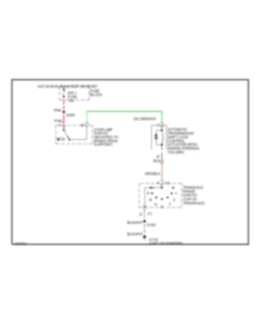
Shift Interlock Wiring Diagram for Oldsmobile Silhouette GL 2001
List of elements for Shift Interlock Wiring Diagram for Oldsmobile Silhouette GL 2001:
- Automatic transmission shift lock control actuator (btsi) (inside steering column)
- Btsi
- Fuse block
- G110 (left of starter)
- Hot in run, bulb test or start
- Ign 1 fuse 10a
- Pnk
- Pnk a
- S106
- S209
- Stoplamp switch (mounted to brake pedal support)
- Transaxle range switch (top of transaxle)
STARTING/CHARGING
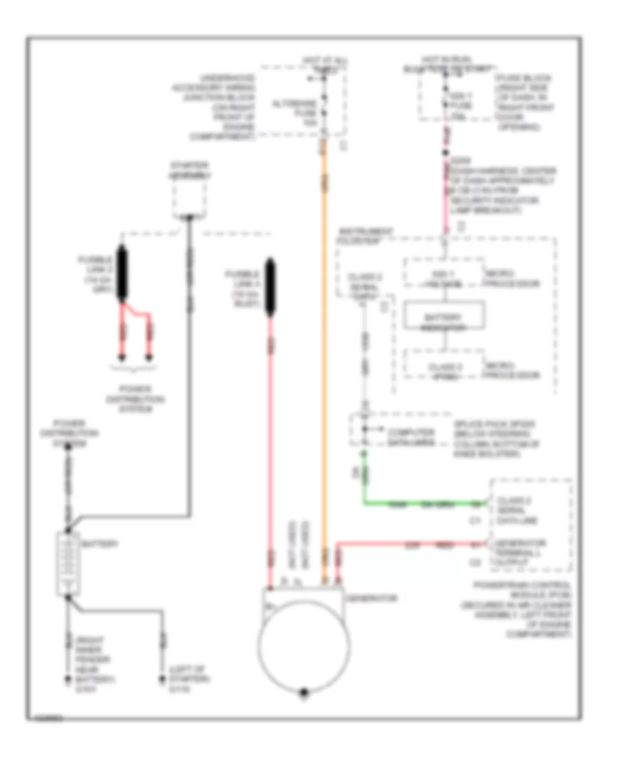
Charging Wiring Diagram for Oldsmobile Silhouette GL 2001
List of elements for Charging Wiring Diagram for Oldsmobile Silhouette GL 2001:
- (left of starter) g110
- (not used)
- (or red)
- (right inner fender near battery) g101
- Alt/sense fuse 10a
- Batt
- Battery
- Battery indicator
- Class 2 (pcm)
- Class 2 serial data
- Class 2 serial data line
- Computer data lines
- E12
- Fuse block (right side of dash, in right front door opening)
- Fusible link a (10 ga- rust)
- Generator
- Generator terminal l output
- Hot at all times
- Hot in run, bulb test or start
- Ign 1 fuse 10a
- Ign 1 voltage
- Instrument cluster
- Micro- processor
- Pnk
- Power distribution system
- Powertrain control module (pcm) (secured in air cleaner assembly, left front of engine compartment)
- Red
- S209 (dash harness, center of dash approximately 8 cm (3 in) from
- Security indicator lamp breakout)
- Splice pack sp205 (below steering column, bottom of knee bolster)
- Starter assembly
- Underhood accessory wiring junction block (on right front of engine compartment)
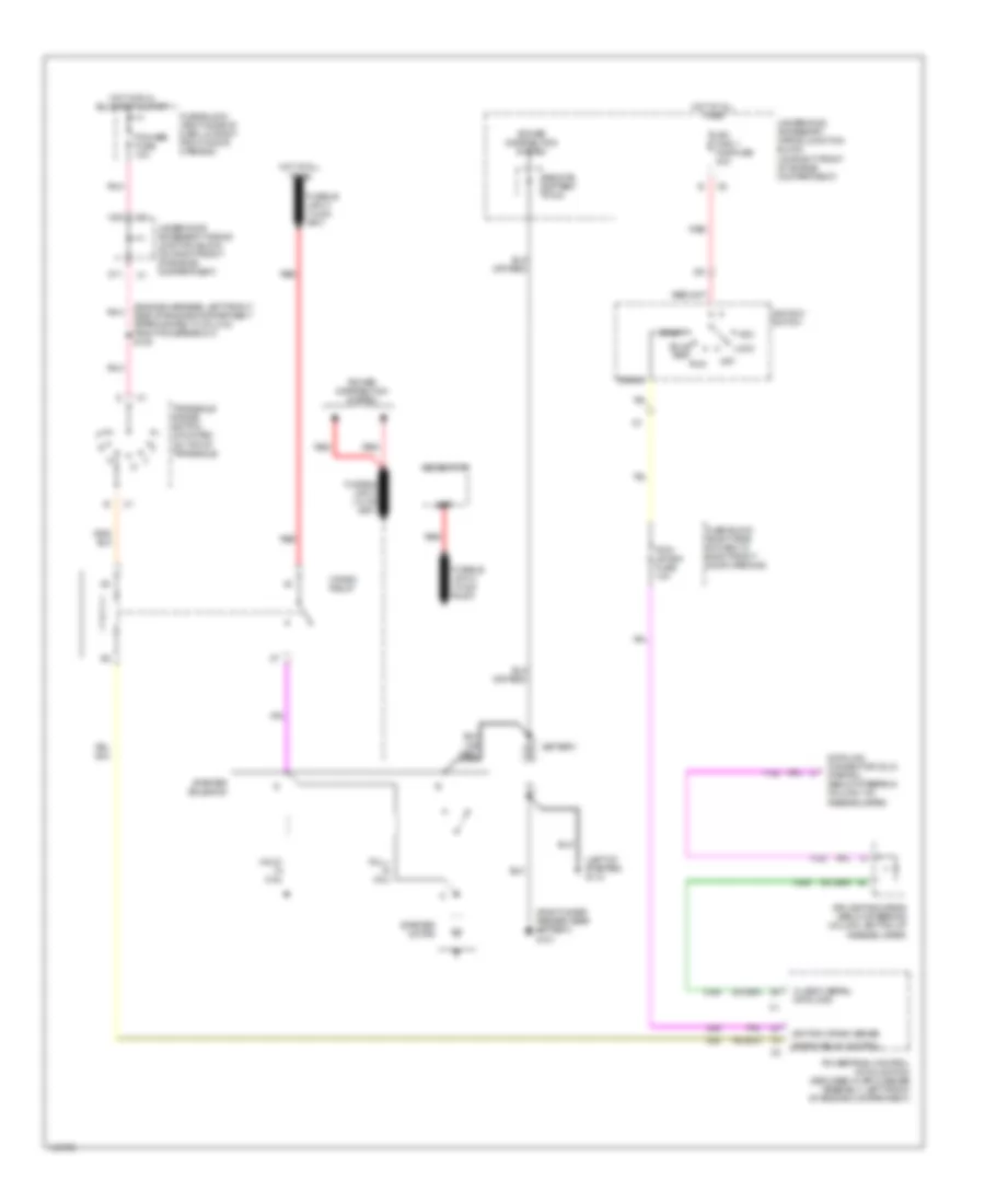
Starting Wiring Diagram for Oldsmobile Silhouette GL 2001
List of elements for Starting Wiring Diagram for Oldsmobile Silhouette GL 2001:
- (engine harness, left front side of engine compartment approximately 8 cm (3 in) from pcm breakout) s108
- (left of starter) g110
- (right inner fender near battery) g101
- Acc
- Batt
- Battery
- Bulb test
- C10
- Class 2 serial data line
- Crank
- Crank relay
- Crank relay control
- D11
- Data link connector (dlc) (partial) (below steering column, on knee bolster)
- Fuse block (right side of dash, in right front door opening)
- Fusible link a (10-ga rust)
- Generator
- Hold- in coil
- Hot at all times
- Hot in run, bulb test & start
- Ign main 1 maxifuse 40a
- Ignition crank sense
- Ignition switch
- Lock
- Off
- Pcm/ crank fuse 10a
- Pcm/abs fuse 10a
- Pnk
- Power distribution system
- Powertrain control module (pcm) (secured in air cleaner assembly, left front of engine compartment)
- Pull- in coil
- Red
- Remote battery stud
- Run
- Splice pack sp205 (below steering column, bottom of knee bolster)
- Start
- Starter motor
- Starter solenoid
- Transaxle range switch (mounted on top of transaxle)
- Underhood accessory wiring junction block (on right front of engine compartment)
SUPPLEMENTAL RESTRAINTS
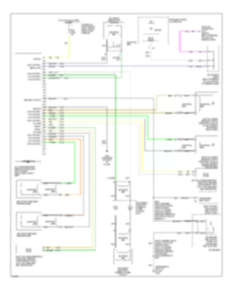
Supplemental Restraint Wiring Diagram for Oldsmobile Silhouette GL 2001
List of elements for Supplemental Restraint Wiring Diagram for Oldsmobile Silhouette GL 2001:
- (body harness, front of right "b" pillar approximately 26 cm (10 inches) from inflatable restraint sensing & diagnostic module breakout) s303
- (near base of right "b" pillar) g305
- (partial) (below steering column, on knee bolster)
- 12v
- A10
- A11
- A12
- A13
- A14
- A15
- A16
- A17
- A18
- Air bag
- Body control module (bcm) (below right side of dash)
- Case ground
- Data link connector (dlc)
- Driver seat
- Driver seat belt input
- Driver seat belt switch (open with driver seat belt buckled)
- Fuse block (right side of dash, in right front door opening)
- G305 (near base of right "b" pillar)
- Ground
- High control
- Hot in run, bulb test & start
- Ignition
- Inflatable restraint ip module
- Inflatable restraint sensing & diagnostic module (sdm) (below right front seat)
- Inflatable restraint steering wheel module
- Inflatable restraint steering wheel module coil
- Instrument panel cluster (ipc)
- Left front seat belt pretensioner
- Left inflatable restraint front side impact module (on left side of driver seat back cover)
- Left inflatable restraint side impact sensor (inside base of left "b" pillar, near seat belt retractor)
- Low control
- Nca
- Right front seat belt pretensioner
- Right inflatable restraint front side impact module (on right side of passenger seat back cover)
- Right inflatable restraint side impact sensor (inside base of right "b" pillar, near seat belt retractor)
- S304 (body harness, right front door approximately 28 cm (11 inches) from inflatable restraint sensing & diagnostic module breakout)
- Sdm fuse 15a
- Seat belt switch
- Serial data
- Shorting bar
- Signal
- Solid state
- Splice pack sp205 (below steering column, bottom of knee bolster)
- Tan
- Voltage
TRANSMISSION
3.4L
3.4L VIN E, A/T Wiring Diagram, 4T65-E for Oldsmobile Silhouette GL 2001
List of elements for 3.4L VIN E, A/T Wiring Diagram, 4T65-E for Oldsmobile Silhouette GL 2001:
- 1-2 shift sol
- 2-3 shift sol
- 5v reference a
- A/t sensor hi
- A/t sensor lo
- Automatic transaxle (4t65-e)
- Automatic transaxle fluid pressure manual valve position switch
- Automatic transaxle fluid temperature sensor
- Automatic transaxle input shaft speed sensor
- Battery in
- D2 sw
- D3 sw
- D4 sw
- Data link connector (dlc) (partial) (below steering column, on knee bolster)
- Ecm sense fuse 10a
- Ect sensor in
- Engine coolant temperature (ect) sensor (on top left rear of engine)
- G113 (in engine compt, left of starter)
- Hot at all times
- Hot in run, bulb test or start
- I/p fuse block (right side of dash, in right front door opening)
- Ign
- Ign 0
- Ign 1
- Ign 1 fuse 10a
- Ignition in
- Instrument panel cluster
- Lo sw
- Manifold absolute pressure (map) sensor (on top right side of engine)
- Map sensor return
- Mil ctrl
- Park/neutral position switch (mounted on top of transaxle)
- Pc sol hi
- Pc sol lo
- Pcm ground
- Pcm/ passkey/ cluster fuse 10a
- Pnk
- Powertrain control module (pcm) (secured in air cleaner assembly, left front of engine compt)
- Pressure control sol valve
- Red
- Rev sw
- S106
- S110 (fuel inj harn, center of engine)
- S209
- S210
- Ser class ii data
- Service engine soon ind
- Sp205 (below steering column)
- Stoplamp switch (mounted on top of brake pedal support)
- Stoplight switch, body control module (bcm), rear door actuator control modules
- Tan
- Tcc fuse 10a
- Tcc pwm sol
- Tcc rel sw
- Tcc release in
- Tcc/ brake switch
- Tcc/brake sw in
- Tft sensor gnd
- Tft sensor in
- Theft deterrent control module
- Throttle position (tp) sensor (on top of engine, on throttle assembly)
- Tp sensor in
- Tp sensor return
- Tr sw in-a
- Tr sw in-b
- Tr sw in-c
- Tr sw in-p
- Trans range a
- Trans range b
- Trans range c
- Underhood fuse block (in engine compt, front of right wheelhouse, above battery)
- Vehicle speed sensor (vss) (mounted to right side of transaxle)
- Vss hi (signal)
- Vss lo (ground)
TRUNK, TAILGATE, FUEL DOOR
Left Sliding Door Wiring Diagram for Oldsmobile Silhouette GL 2001
List of elements for Left Sliding Door Wiring Diagram for Oldsmobile Silhouette GL 2001:
- (body harn, front of left "b" pillar) s340
- (sliding door harn, inside left rear door) s816
- 12v
- 5v ref
- A8 c1
- Ajar
- Alarm
- B/u lamp fuse 10a
- Battery
- Body control module (below right side of dash)
- C2 c4
- Cable motor
- Cable motor ctrl
- Clutch
- Clutch ctrl hi
- Clutch ctrl lo
- Control
- Detent sw input
- Engine controls system
- Fuse block (right side of dash)
- G305 (base of right "b" pillar)
- G998 (lower rt "d" pillar)
- Ground
- Hi current battery
- Hot at all times
- Hot in run, bulb test, or start
- Ign 1 fuse 10a
- Ignition
- Interior lamp & multi-function switch assembly
- Interior lights system
- Latched
- Left door lock switch plate (door mounted)
- Left door lock switch plate (pillar mounted)
- Left sliding door module (part of the rear side door actuator motor, in the left quarter panel above wheelwell)
- Nca
- Off
- Open
- Optical sensor
- Park
- Park neutral pos sw
- Pnk
- Power sliding door
- Power sliding door detent switch
- Power sliding door on/off switch
- Power sliding door open/ close switch (middle of left "b" pillar)
- Power sliding door open/ close switch (momentary)
- Power sliding door unlatch actuator
- Pwr sldg dr circuit breaker 30a
- Pwr sliding door rel
- Radio fuse 10a
- Rear door actuator (left quarter panel, above wheelwell)
- Remote control door lock receiver (behind center of dash, underside of dash trim, near windshield defrost vent)
- Return
- S303
- S322
- S326
- S337
- S390
- Signal
- Sliding door sw sig
- Sliding door syst sw
- Slip ring
- Sw clsd w/dr handle pulled
- Transaxle park position input sig
- Transaxle range switch (mounted on top of transaxle)
- Underhood junction block (on right front of engine compt)
- Vehicle speed sensor
Right Sliding Door Wiring Diagram for Oldsmobile Silhouette GL 2001
List of elements for Right Sliding Door Wiring Diagram for Oldsmobile Silhouette GL 2001:
- (roof harn, right "b" pillar, approx 27 cm from power sliding door open/close switch) s392
- (sliding door harn, inside right rear door) s817
- 12v
- 5v ref
- A8 c1
- Ajar
- Alarm
- B/u lamp fuse 10a
- Battery
- Body control module (below right side of dash)
- C2 c4
- Cable motor
- Cable motor ctrl
- Clutch
- Clutch ctrl hi
- Clutch ctrl lo
- Control
- Detent sw input
- Engine controls system
- Fuse block (right side of dash)
- G305 (base of right "b" pillar)
- G998 (lower rt "d" pillar)
- Ground
- Hi current battery
- Hot at all times
- Hot in run, bulb test, or start
- Ign 1 fuse 10a
- Ignition
- Interior lamp & multi-function switch assembly
- Interior lights system
- Latched
- Nca
- Of left rear wheelwell) s324
- Off
- Open
- Optical sensor
- Park
- Park neutral pos sw
- Pnk
- Power sliding door
- Power sliding door detent switch
- Power sliding door on/off switch
- Power sliding door open/ close switch (middle of right "b" pillar)
- Power sliding door open/ close switch (momentary)
- Power sliding door unlatch actuator
- Pwr sldg dr circuit breaker 30a
- Pwr sliding door rel
- Radio fuse 10a
- Rear door actuator (right quarter panel, above wheelwell)
- Remote control door lock receiver (behind center of dash, underside of dash trim, near windshield defrost vent)
- Return
- Right door lock switch plate (door mounted)
- Right door lock switch plate (pillar mounted)
- Right sliding door module (part of the rear side door actuator motor, in the right quarter panel above wheelwell)
- S303
- S322
- S326
- S337
- S390
- Signal
- Sliding door sw sig
- Sliding door syst sw
- Slip ring
- Sw clsd w/dr handle pulled
- Transaxle park position input sig
- Transaxle range switch (mounted on top of transaxle)
- Underhood junction block (on right front of engine compt)
- Vehicle speed sensor
WARNING SYSTEMS
Warning System Wiring Diagrams for Oldsmobile Silhouette GL 2001
List of elements for Warning System Wiring Diagrams for Oldsmobile Silhouette GL 2001:
- Accy1
- Battery
- Body control module (bcm) (below right side of dash)
- C1 e5
- C12
- C13
- C14
- C15
- Chime request
- Ctsy lamp fuse 10a
- D12
- Driver's door ajar input
- Driver's seat belt switch (inside right half of driver's seat belt)
- Exterior lights system
- Fasten belts warning ind
- Fuse block
- G201 (right side of dash)
- G305 (base of right "b" pillar)
- G308 (lower left "b" pillar)
- Ground
- Head
- Headlamp & i/p lamp dimmer switch
- Headlights system
- Hot at all times
- Hot in accy or run
- Hot in run, bulb test or start
- Ign 1 fuse 10a
- Ignition 1
- Ignition key alarm switch
- Ignition key switch input
- Instru- ment cluster
- Left front door lock (ajar indicator switch)
- Left turn input
- Low oil/fuel message
- Mall/ cluster fuse 10a
- Nca
- Off
- Park
- Park lamps off input
- Park lp fuse 20a
- Pnk
- Powertrain control module (pcm) (secured in air cleaner assembly, left front of eng compt)
- Right turn input
- S209
- S212
- S227
- S230
- S232 (i/p harn, right side of dash approx 17 cm from radio breakout)
- S233 (i/p harn, left side of dash approx 4 cm from radio breakout)
- S282 (dash harness, left side of dash, 4 cm from cigar lighter breakout)
- S304 (body harn, right front door, approx 28 cm from inflatable restraint control module breakout)
- S333
- S504
- Seat belt switch input
- Seat belt tell tale
- Tan
- Trunk, tailgate & fuel doors system
- Turn signal & headlamp dimmer switch & windshield wiper & windshield washer switch
- Underhood junction block
- Vehicle speed input
WIPER/WASHER
Front Wiper/Washer Wiring Diagram for Oldsmobile Silhouette GL 2001
List of elements for Front Wiper/Washer Wiring Diagram for Oldsmobile Silhouette GL 2001:
- (in dash harness, right side of dash approximately 14 cm (6 in) from grommet, on right side of bulkhead, left of right strut tower) s249
- (right side of dash, left of heater-a/c vent) g201
- Delay
- Frt/wpr/wshr fuse 25a
- Fuse block (right side of dash, in right front door opening)
- Ground
- Hot in accy or run
- Mist
- Mux1
- Mux2
- Off
- Red
- Washer switch
- Windshield washer pump (in front washer solvent container)
- Windshield wiper motor (on right rear of engine compartment)
- Windshield wiper/washer switch
- Wiper switch
Rear Wiper/Washer Wiring Diagram for Oldsmobile Silhouette GL 2001
List of elements for Rear Wiper/Washer Wiring Diagram for Oldsmobile Silhouette GL 2001:
- (dash harness, right side of dash approximately, 5 cm (2 in) from radio breakout, within radio breakout) s245
- (liftgate harness center of liftgate approximately 7 cm (3 in) from liftgate lock cylinder switch breakout) s460
- (lower left "d" pillar) g999
- (right side of dash, left of heater-a/c vent) g201
- +dn
- +up
- Delay
- Fuse block (right side of dash, in right front door opening)
- Hot in accy or run
- Illum
- Interior lights system
- Multi- function switch
- On right side of bulkhead, left of right strut tower) s280
- Park
- Rear window washer pump (in rear washer solvent container)
- Rear window wiper motor (on center of liftgate)
- Rear window wiper/ washer switch
- Rr wpr/wshr fuse 20a
- Run
- S262
- Wash
- Wiper motor