Diagram sections — 26 (53 total)
AIR CONDITIONING ANTI-LOCK BRAKES ANTI-THEFT COMPUTER DATA LINES COOLING FAN CRUISE CONTROL DEFOGGERS ENGINE PERFORMANCE EXTERIOR LIGHTS GROUND DISTRIBUTION HEADLIGHTS HORN INSTRUMENT CLUSTER INTERIOR LIGHTS POWER DISTRIBUTION POWER DOOR LOCKS POWER MIRRORS POWER TOP/SUNROOF POWER WINDOWS RADIO SHIFT INTERLOCK STARTING/CHARGING SUPPLEMENTAL RESTRAINTS TRANSMISSION WARNING SYSTEMS WIPER/WASHER
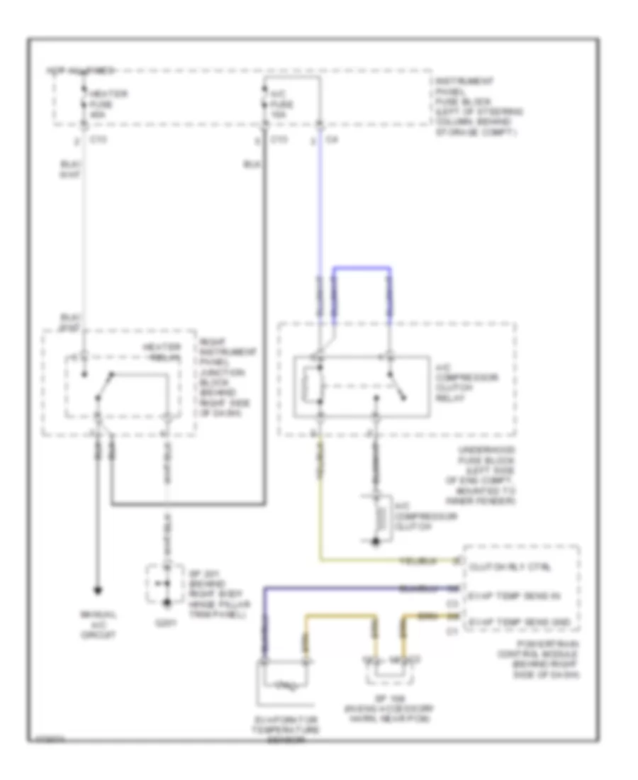
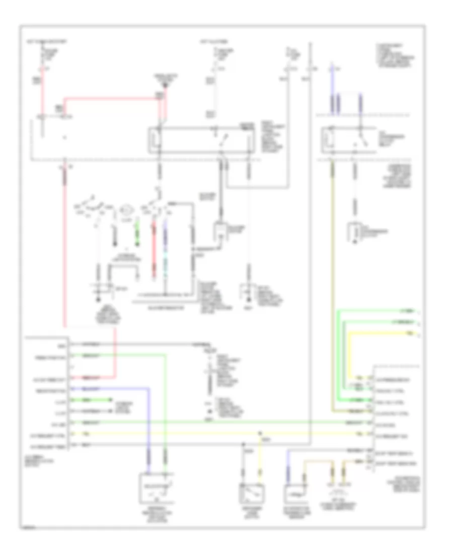
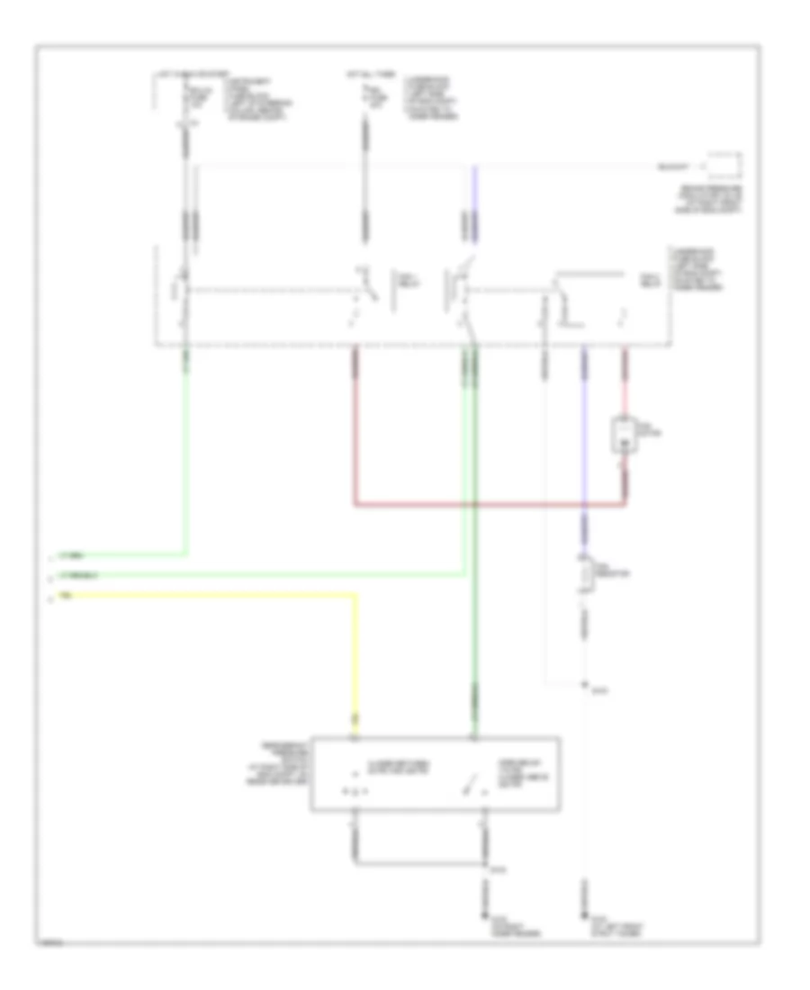
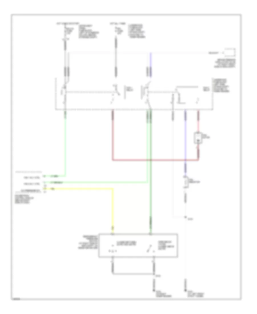
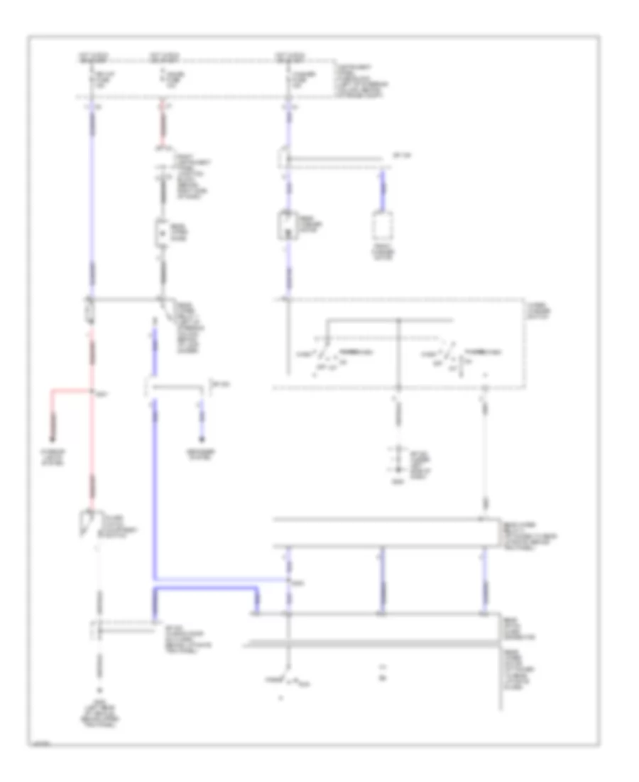
AIR CONDITIONING Compressor Wiring Diagram for Pontiac Vibe GT 2003 List of elements for Compressor Wiring Diagram for Pontiac Vibe GT 2003: 19 A/c compressor clutch A/c compressor clutch relay A/c fuse 10a C13 Clutch rly ctrl Evap temp sens gnd Evap temp sens in Evaporator temperature sensor G201 Heater fuse 40a Heater relay Hot all times Instrument panel fuse block (left of steering column, behind storage compt) Manual a/c circuit Powertrain control module (behind right side of dash) Right instrument panel junction block (behind right side of dash) Sp 108 (in eng accessory harn, near pcm) Sp 201 (behind right body hinge pillar trim panel) Underhood fuse block (left side of eng compt, mounted to inner fender) Manual A/C Wiring Diagram (1 of 2) for Pontiac Vibe GT 2003 List of elements for Manual A/C Wiring Diagram (1 of 2) for Pontiac Vibe GT 2003: 53 A/c compressor clutch A/c compressor clutch relay A/c fresh recirculation switch A/c fuse 10a A/c led A/c on sig A/c pressure sw A/c request ctrl A/c request feed A/c request sig A/c sw feed ckt Blower motor Blower motor resistor (at lower right side of firewall, left of blower motor) Blower resistor Blower switch C13 Clutch rly ctrl Defogger mode switch Evap temp sens gnd Evap temp sens in Evaporator temperature sensor Fan 1 rly ctrl Fan 2 rly ctrl Fresh position G201 G201 (behind right body hinge pillar trim panel) Gauge fuse 10a Gnd Headlights system (drl) Heater fuse 40a Heater relay High Hot all times Hot in run or start Illum Instrument panel fuse block (left of steering column, behind storage compt) Interior lights system Low Off Powertrain control module (behind right side of dash) Recir position Red Refresh/ recirculation air inlet actuator Right instrument panel junction block (behind right side of dash) Right instrument panel junction c3 block (behind right side of dash) S223 S224 S225 Solid state Sp 108 (in eng accessory harn, near pcm) Sp 201 Sp 201 (behind right body hinge pillar trim panel) Underhood fuse block (left side of eng compt, mounted to inner fender) Manual A/C Wiring Diagram (2 of 2) for Pontiac Vibe GT 2003 List of elements for Manual A/C Wiring Diagram (2 of 2) for Pontiac Vibe GT 2003: 18 Brake pressure modulator valve (at right front side of eng compt) Closed between 28 psi and 455 psi Ecu-ig fuse 10a Fan 1 relay Fan 2 relay Fan motor Fan resistor G102 (on right inner fender) G103 (at left front strut tower) Hot all times Hot in run or start Instrument panel fuse block (left of steering column, behind storage compt) Open below 178 psi closed above 220 psi Rdi fuse 40a Refrigerant pressure switch (at right side of eng compt, on receiver driver) S102 S103 Underhood fuse block (left side of eng compt, mounted to inner fender)
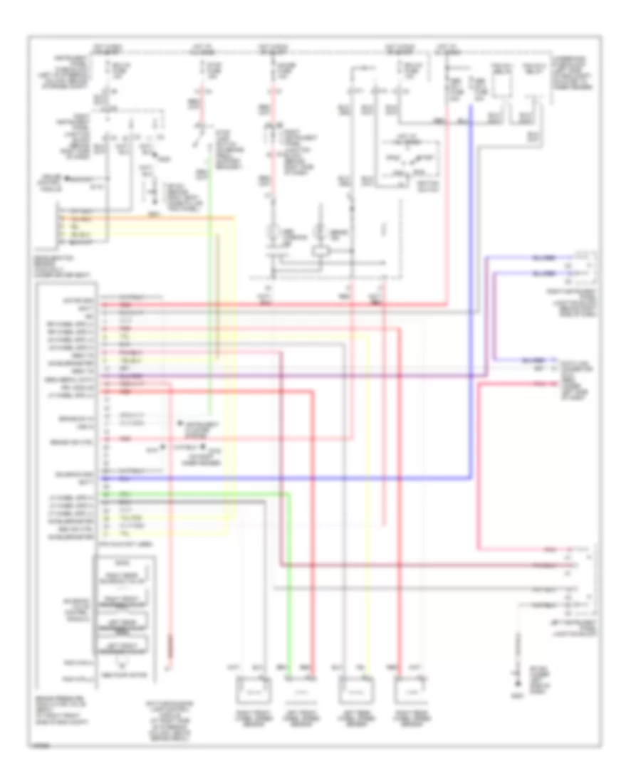
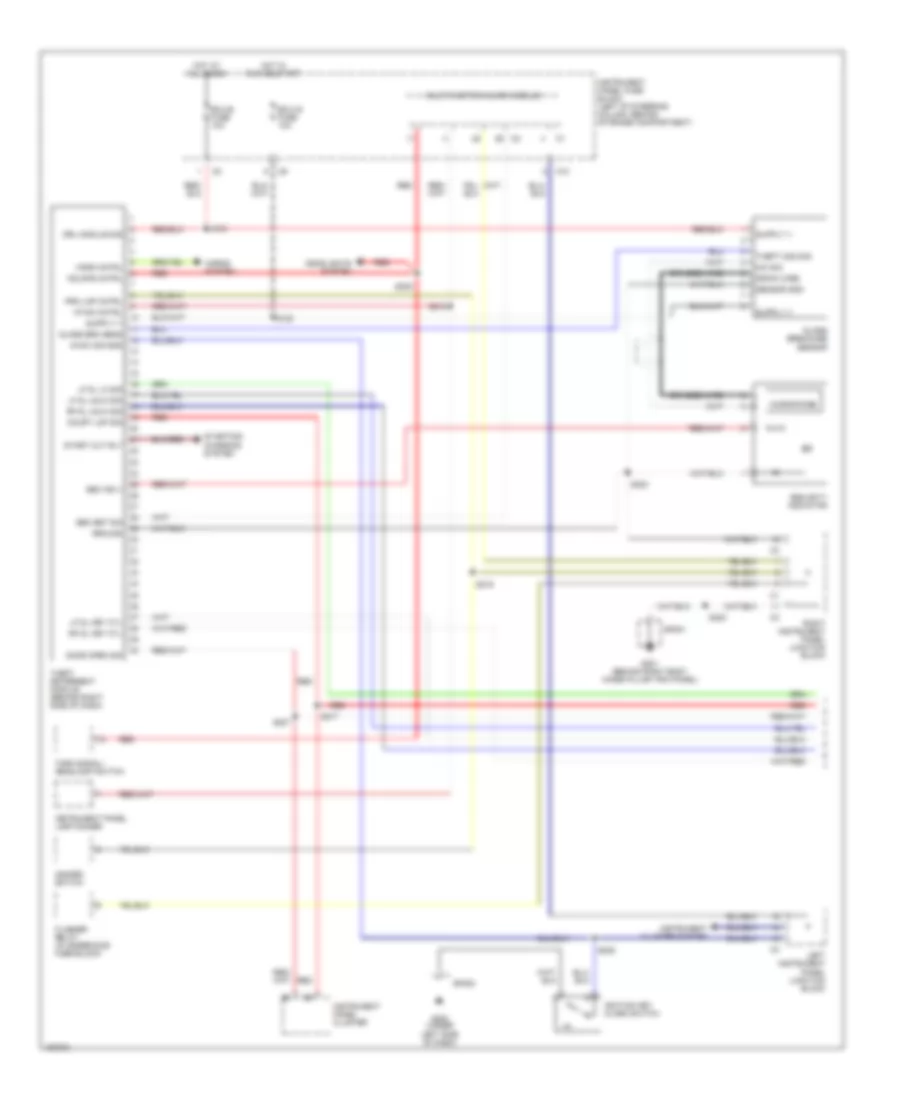
ANTI-LOCK BRAKES Anti-lock Brakes Wiring Diagram for Pontiac Vibe GT 2003 List of elements for Anti-lock Brakes Wiring Diagram for Pontiac Vibe GT 2003: 71 (on right inner fender) (pin 32-40 not used) Abs ind ctrl Abs no 1 fuse 30a Abs no 2 fuse 40a Abs pump motor Abs warning ind Acc Accelerometer Batt Brake ind Brake ind ctrl Brake pressure modulator valve (bpmv) (at right front side of eng compt) Brake sw in C11 C12 Cruise control module Data link connector (dlc) obd2 (under left side of dash) Daytime running lamp control module (at right side of steering column, above brake pedal) Deceleration sensor (awd only) (under driver seat) Drl module Ecu-ig fuse 10a Fan no 1 relay Fan no 2 relay G102 G200 G201 Gauge fuse 10a Hot at all times Hot in run or start Ign Ignition switch Instrument cluster system Instrument panel fuse block (left of steering column, behind storage compt) Left front solenoid valve Left front wheel speed sensor Left instrument panel junction block Left rear solenoid valve Left rear wheel speed sensor Lf wheel spd hi Lf wheel spd lo Lr wheel spd hi Lr wheel spd lo Motor gnd Obd2 serial data Obd2 ts Off Pmp mtr hi Pmp mtr lo Pnk Red Right front solenoid valve Right front wheel speed sensor Right instrument panel junction block (behind right side of dash) Right rear solenoid valve Right rear wheel speed sensor Rr wheel spd hi Rr wheel spd l0 Run S101 S115 S222 Solenoid gnd Solenoid valve control signals Sp 200 (under left side of dash) Sp 201 (behind right body hinge pillar trim panel) Start Stop fuse 15a Stop lamp switch (on brake pedal support bracket) Underhood fuse block (left side of eng compt, mounted to inner fender) Vss in
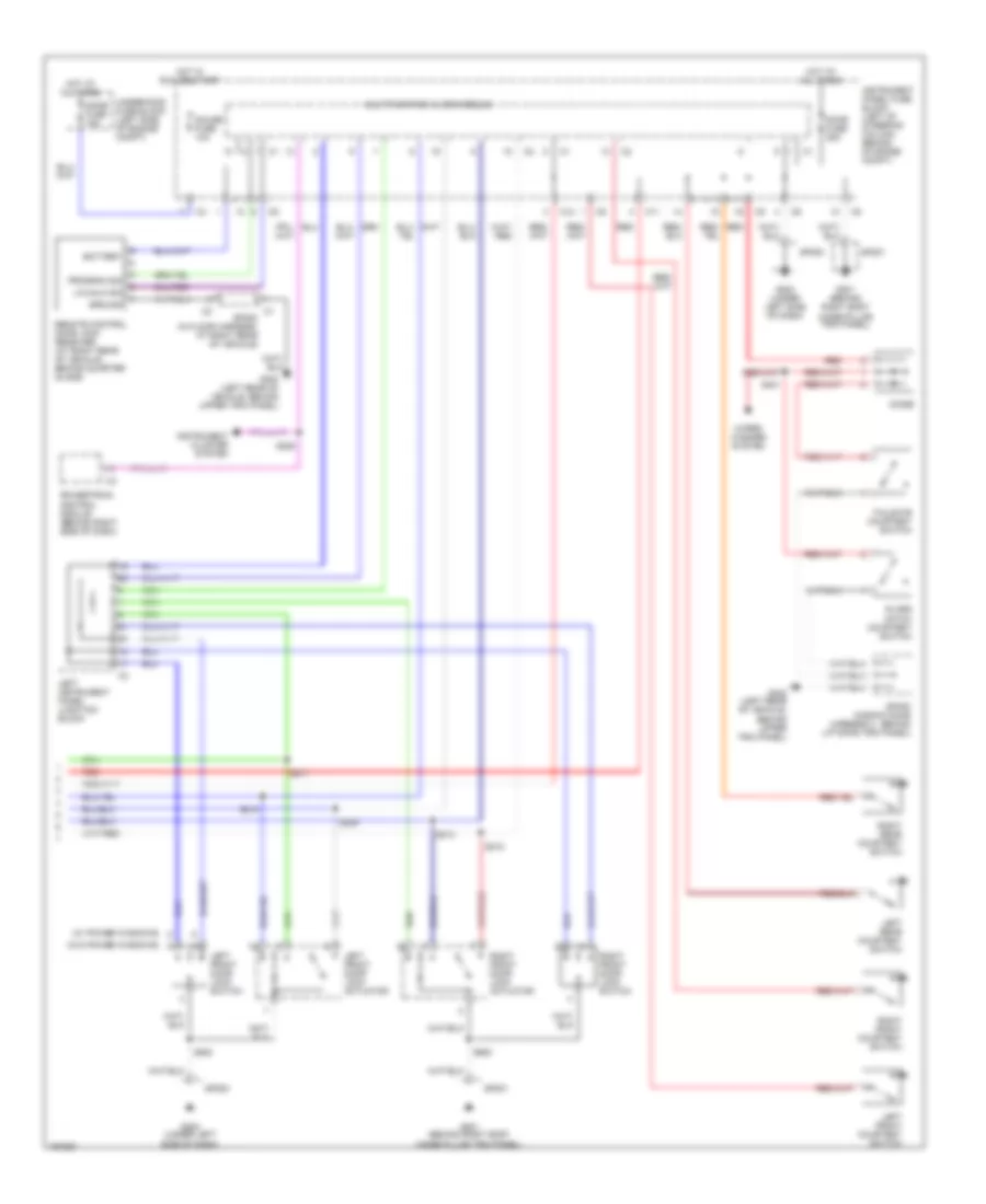
ANTI-THEFT Anti-theft Wiring Diagram (1 of 2) for Pontiac Vibe GT 2003 List of elements for Anti-theft Wiring Diagram (1 of 2) for Pontiac Vibe GT 2003: 60 Braided wire C10 Court lmp sig Door open sig Drain wire Drl module sig Ecu-b fuse 10a Ecu-ig fuse 10a Flasher relay (in underhood fuse block) G200 (under left side of dash) G201 (behind right body hinge pillar trim panel) Glass breakage sensor Glass brk sens Ground Hazard switch Hdlmps cntrl Headlights system Horn cntrl Horns system Hot at all times Hot in run or start I/p dim cntrl Ig sw sig gnd Ignition key alarm switch Instrument cluster system Instrument panel cluster Instrument panel fuse block (left of steering column, behind storage compartment) Instrument panel lamp dimmer Left instrument panel junction block Lf dl key cyl Lf dl lk sig Lf dl unlk sig Mic sig Microphone Multifunction alarm module Prk lmp cntrl Red Rf dl key cyl Rf dl unlk sig Right instrument panel junction block S121 S122 S205 S207 S215 S216 S217 S222 S223 Sec ind v Sec set sig Security indicator Sensor gnd Sp200 Sp201 Start cut rly Starting/ charging system Theft deterrent module (behind right side of dash) Theft mod sig Turn signal/ headlamp switch Anti-theft Wiring Diagram (2 of 2) for Pontiac Vibe GT 2003 List of elements for Anti-theft Wiring Diagram (2 of 2) for Pontiac Vibe GT 2003: 49 (w/ power windows) (w/o power windows) Battery C1 sp300 (in floor harness, at right rear of vehicle) C11 C12 Diode Dome fuse 15a Door fuse 25a G200 (under left side of dash) G201 (behind right body hinge pillar trim panel) G300 (left rear of vehicle, behind upper trim panel) Gauge fuse 10a Glass hatch courtesy switch Ground Hot at all times Hot in run or start Instrument cluster system Instrument panel fuse block (left of steering column, behind storage compt) Left front courtesy switch Left front door lock actuator Left front door lock switch Left instrument panel junction block Left rear courtesy switch Lk/unlk sig Multifunction alarm module Powertrain control module (behind right side of dash) Program sig Red Remote control door lock receiver (at right rear of vehicle, behind quarter glass) Right front courtesy switch Right front door lock actuator Right front door lock switch Right rear courtesy switch S206 S209 S210 S211 S212 S213 S401 S500 S600 Sp200 Sp201 Sp400 (in back door harness 2, behind liftgate trim panel) Tailgate courtesy switch Underhood fuse block (left side of engine compt) Wiper/ washer system
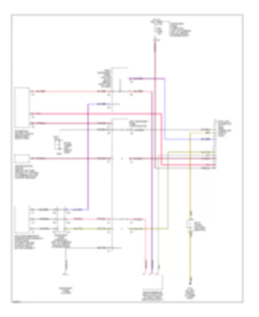
COMPUTER DATA LINES Computer Data Lines Wiring Diagram for Pontiac Vibe GT 2003 List of elements for Computer Data Lines Wiring Diagram for Pontiac Vibe GT 2003: 17 Brake pressure modulator valve (at right front side of eng compt) C10 Cruise control module (behind left side of dash, at top side of steering column support bracket) Data link connector (dlc) obd2 (under left side of dash) G104 (on left side of cylinder head) G200 Hot at all times Inflatable restraint steering and diagnostic module (sdm) (at front center console, below shifter assenbly) Instrument panel cluster Instrument panel fuse block (left of steering column, behind storage compt) Left instrument panel junction block Obd fuse 7.5a Pnk Powertrain control module (behind right side of dash) Right instrument panel junction block (behind right side of dash) Sp 200 (under left side of dash) Sp107 (in eng acc harn, near pcm)
COOLING FAN Cooling Fan Wiring Diagram for Pontiac Vibe GT 2003 List of elements for Cooling Fan Wiring Diagram for Pontiac Vibe GT 2003: 22 A/c pressure sw Brake pressor modulator valve (at right front side of eng compt) Closed between 28 psi and 455 psi Ecu-ig fuse 10a Fan 1 relay Fan 1 rly ctrl Fan 2 relay Fan 2 rly ctrl Fan motor Fan resistor G102 (on right inner fender) G103 (at left front strut tower) Hot all times Hot in run or start Instrument panel fuse block (left of steering column, behind storage compt) Open below 178 psi closed above 220 psi Powertrain control module (behind right side of dash) Rdi fuse 40a Refrigerant pressure switch (at right side of eng compt, on receiver driver) S102 S103 Underhood fuse block (left side of eng compt, mounted to inner fender)
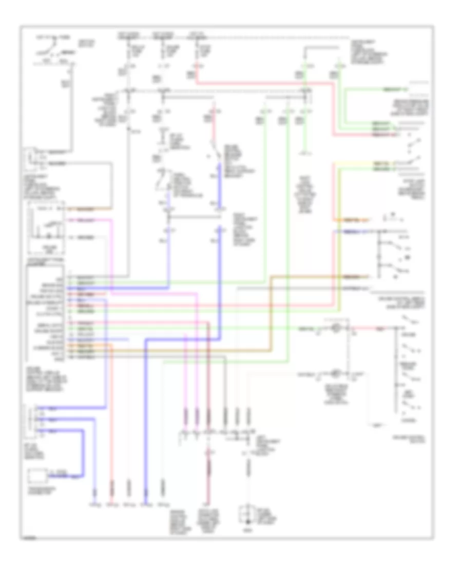
CRUISE CONTROL Cruise Control Wiring Diagram for Pontiac Vibe GT 2003 List of elements for Cruise Control Wiring Diagram for Pontiac Vibe GT 2003: 54 (fwd) (awd) Acc Acc + Brake pressure modulator valve (at right front side of eng compt) Brake sig C11 C12 Cancel Clutch ctrl Coast + Cruise Cruise control module (behind left side of dash, at top side of steering column support bracket) Cruise control release switch (m/t) (on clutch pedal support bracket) Cruise control servo (at left rear side of eng compt) Cruise control switch Cruise ind Cruise ind ctrl Cruise interrupt Cruise on/off Data link cnnector (dlc) obd2 (under left side of dash) Ecu-ig fuse 10a Engine control module (behind right side of dash) G200 Gauge fuse 10a Gnd Hot at all times Hot in run or start Idle sig Ign Ignition switch Inflatable restraint steering wheel module coil Instrument panel cluster Instrument panel fuse block (left of steering column, behind storage compt) Left instrument panel junction block Lock Overdrive sig Park/ neutral position switch (on front of transaxle) Pnp sw sig Red Resume/ accel Right instrument panel junction block (behind right side of dash) Run S115 Serial data Set/ coast Shift lock control mdule (attacted to right side of shift lever) Sp 107 (in eng harn, near pcm) Sp 108 (in eng acc harn, near pcm) Sp 200 (under left side of dash) Start Stop fuse 15a Stop lamp switch (on bracket, above brake pedal) Transmission connector Vss in
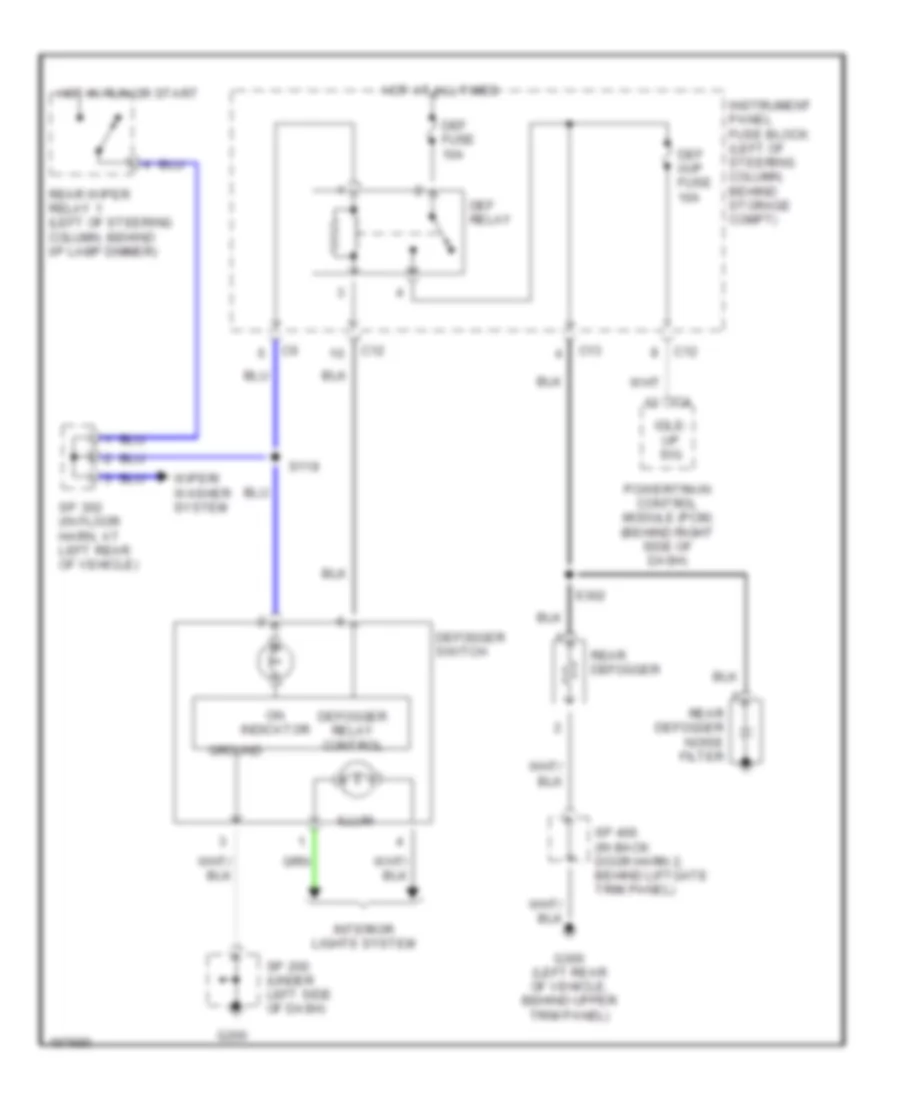
DEFOGGERS Defoggers Wiring Diagram for Pontiac Vibe GT 2003 List of elements for Defoggers Wiring Diagram for Pontiac Vibe GT 2003: 27 C12 C13 Def fuse 10a Def i/up fuse 10a Def relay Defogger relay control Defogger switch G200 G300 (left rear of vehicle, behind upper trim panel) Ground Hot at all times Hot in run or start Idle- up sig Illum Instrument panel fuse block (left of steering column, behind storage compt) Interior lights system On indicator Powertrain control module (pcm) (behind right side of dash) Rear defogger Rear defogger noise filter Rear wiper relay 1 (left of steering column, behind i/p lamp dimmer) S118 S302 Sp 200 (under left side of dash) Sp 302 (in floor harn, at left rear of vehicle) Sp 400 (in back door harn 2, behind liftgate trim panel) Wiper/ washer system
ENGINE PERFORMANCE
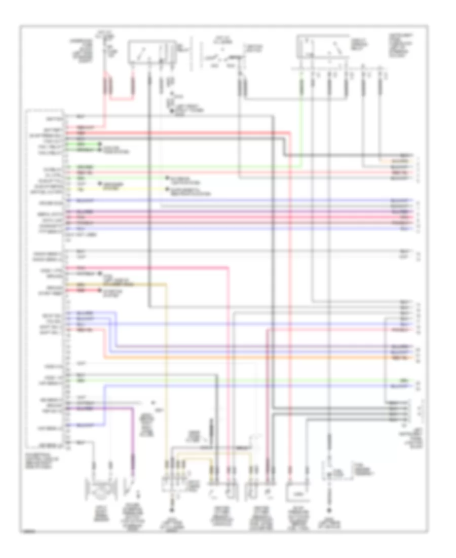
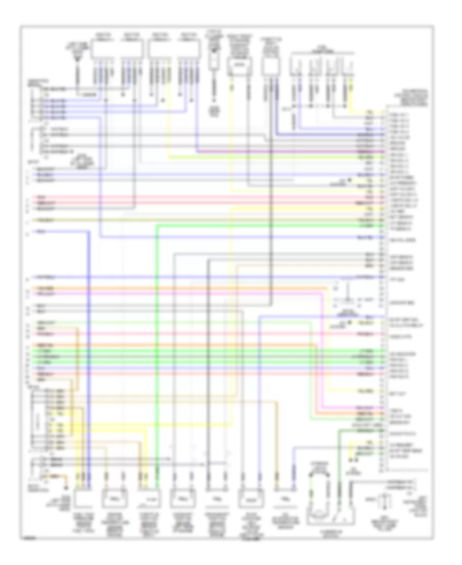
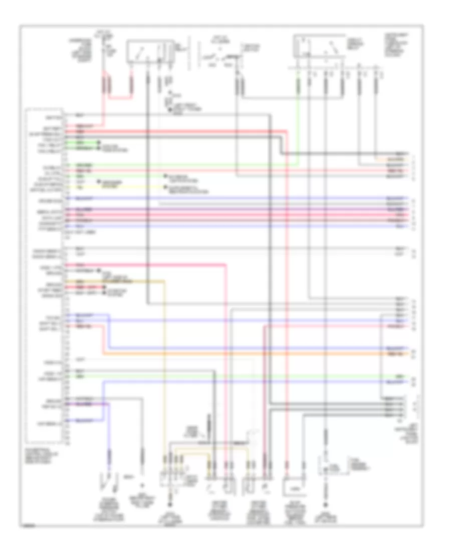
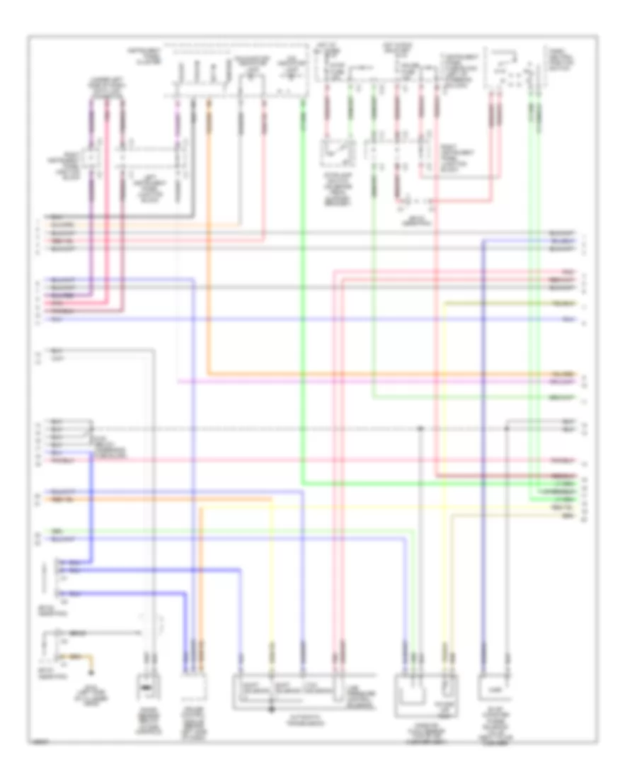
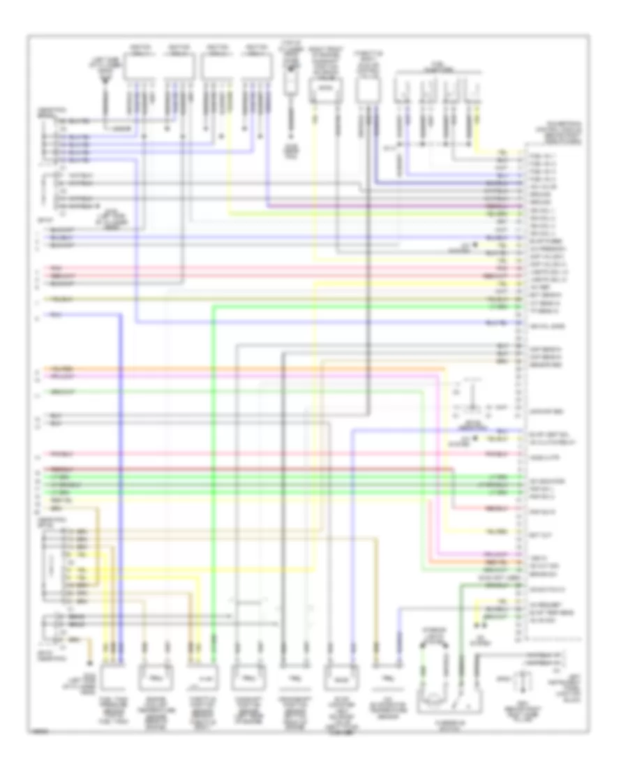
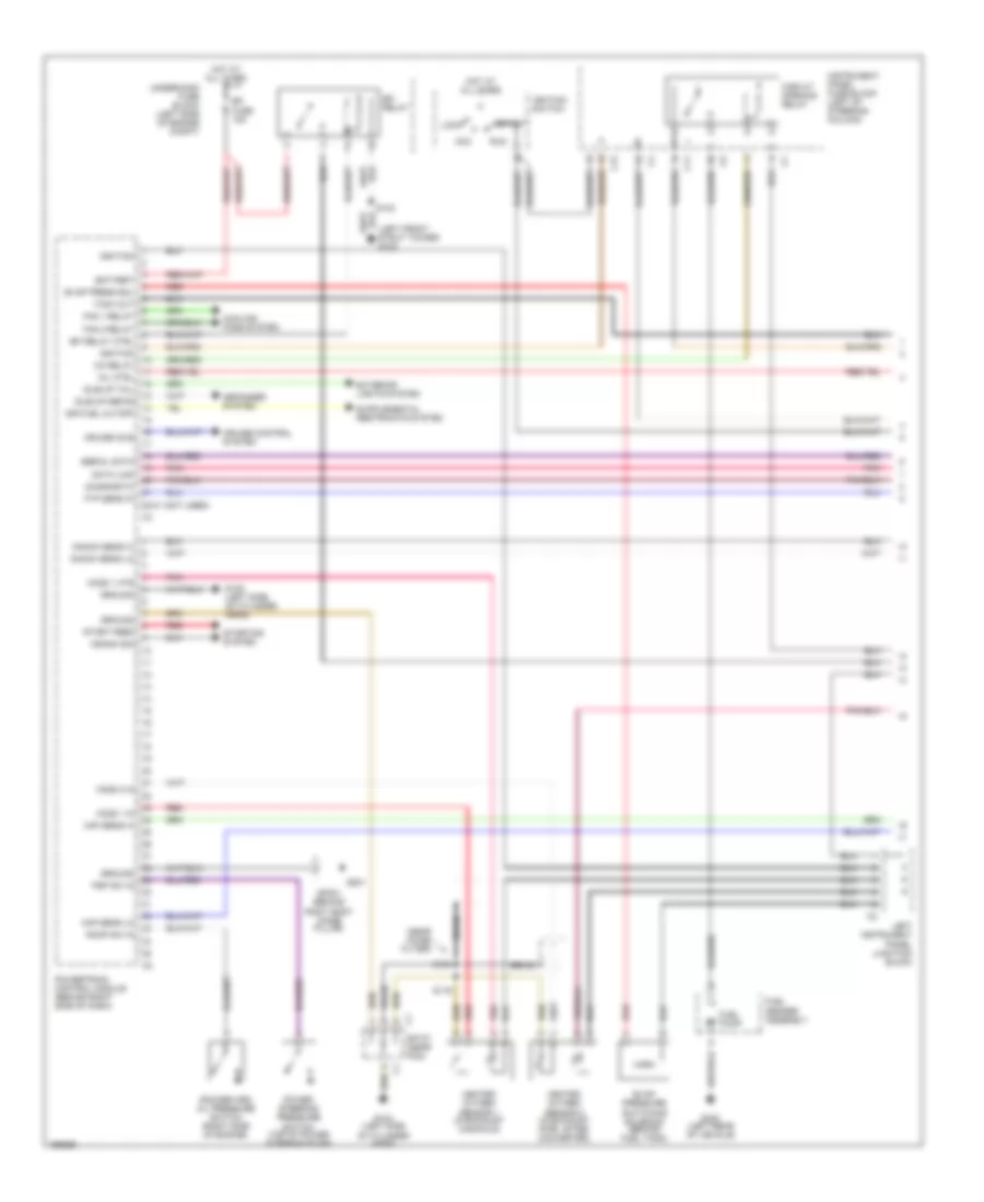
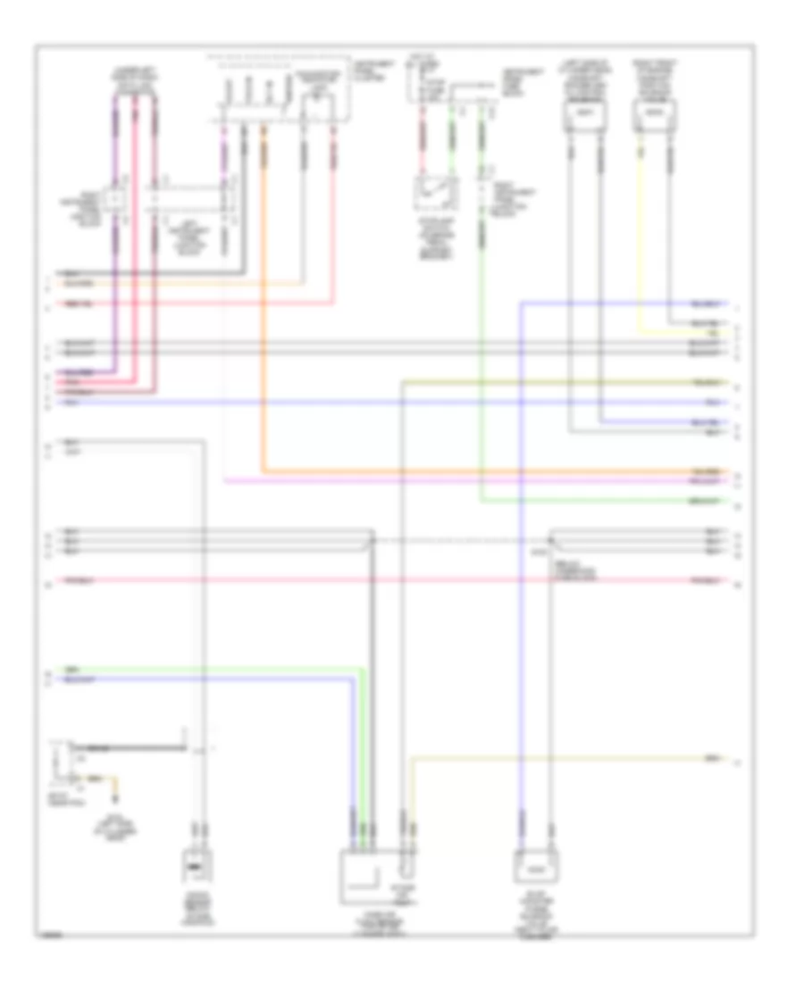
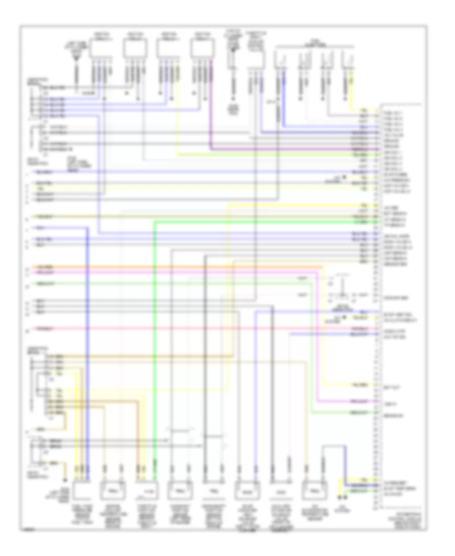
1.8L VIN 8 1.8L VIN 8, Engine Performance Wiring Diagram, AWD (1 of 3) for Pontiac Vibe GT 2003 List of elements for 1.8L VIN 8, Engine Performance Wiring Diagram, AWD (1 of 3) for Pontiac Vibe GT 2003: 72 (left front strut tower) g103 (near noise filter) 22-31 (not used) Acc Battery Braid C11 C12 Circuit opening relay Co relay Cooling fans system Cruise idle Data link Defogger system Diagnostic Efi fuse 15a Efi relay Evap press sol Evap pressure switching solenoid (behind fuel tank) Exterior lights system Fan 1 relay Fan 2 relay Ftp sens in Fuel pump Fuel sender assembly G104 (left side of cylinder head) G105 (left side of cylinder head) G201 G300 (left rear of vehicle) Ground Heated oxygen sensor 1 (in exhaust manifold) Heated oxygen sensor 2 (in exhaust pipe, after converter) Ho2s 1 htr Ho2s 1 in Ho2s 2 in Hot at all times Idle-up defog Idle-up tail Ignition Ignition switch Input shaft speed sensor Instrument panel fuse block (left of steering column) Iss sens hi Iss sens lo Knock sens hi Knock sens lo Left instrument panel junction block Lock Maf sens hi Maf sens lo Mil ctrl Pnk Power steering pressure switch (top of pwr steering pump) Powertrain control module (behind right side of dash) Psp sw in Red Run S103 S104 Serial data Shift sol 1 Shift sol 2 Sir fuel cutoff Sp107 (near pcm) Sp201 (behind right body hinge pillar) Ss st sol Start Start feed Starting system Tach out Tcc sol Underhood fuse block (left side of engine compt) 1.8L VIN 8, Engine Performance Wiring Diagram, AWD (2 of 3) for Pontiac Vibe GT 2003 List of elements for 1.8L VIN 8, Engine Performance Wiring Diagram, AWD (2 of 3) for Pontiac Vibe GT 2003: 40 (below underhood fuse block) (near pcm) sp107 (under left side of dash) data link connector 2nd brake solenoid Automatic transmission Braid C12 Cruise control module (behind Ect in Evap canister purge solenoid valve (next to air cleaner) G104 (left side of cylinder head) Gauge fuse 10a Hot at all times Hot in run or start Ignition Instrument panel cluster Instrument panel fuse block (left of steering column) c11 Intake air temp Intake manifold) Knock sensor (below Left instrument panel junction block Left side of dash) Line pressure control solenoid Malfunction indicator lamp Mass air flow sensor (top of air cleaner assy) O/d indicator lamp Park/ neutral position switch Pnk Right instrument panel junction block Right instrument panel junction c3 block S100 Shift solenoid Sp107 (near pcm) Sp108 (near pcm) Stop fuse 15a Stoplamp switch (on brake pedal support bracket) Tach in Tcc solenoid Transmission fluid temperature sensor Vs out 1.8L VIN 8, Engine Performance Wiring Diagram, AWD (3 of 3) for Pontiac Vibe GT 2003 List of elements for 1.8L VIN 8, Engine Performance Wiring Diagram, AWD (3 of 3) for Pontiac Vibe GT 2003: 79 (left side of cylinder head) g105 (near pcm) sp108 (right front of engine) camshaft position solenoid valve (throttle body) idle air control valvle (top of cylinder head) noise filter +5v ref 20-28 (not used) A/c evaporator temperature sensor A/c press sw A/c system Ac clutch relay Ac on sig Ac request Braid Brake sw Camshaft position sensor (left rear of engine) Ckp sens in Cmp sens in Cmp valve hi Cmp valve lo Cmp/ckp gnd Crankshaft position sensor (bottom front of engine) Ect out Ect sens in Engine coolant temperature sensor (rear of engine) Evap canister vent solenoid valve (next to air cleaner) Evap purge Evap temp sens Evap vent sol Fuel inj 1 Fuel inj 2 Fuel inj 3 Fuel inj 4 Fuel injectors Fuel tank pressure sensor (top of fuel tank) G104 (left side of cylinder head) G105 (left side G201 (behind right body hinge pillar) Ground Ho2s 2 htr Iac valve Iat sens in Ign coil 1 Ign coil 2 Ign coil 3 Ign coil 4 Ign fail safe Ignition coil 1 Ignition coil 2 Ignition coil 3 Ignition coil 4 Interior lights system Left instrument panel junction block Line pc sol hi Line pc sol lo Od cut sig Od indicator Od switch in Of cylinder head) Overdrive switch Pnk Pnp sw 2 Pnp sw d Pnp sw l Pnp sw r Powertrain control module (behind right side of dash) S105 S106 (near pcm) S114 Sensor gnd Sp107 Sp107 (near pcm) Sp108 Sp108 (near pcm) Sp201 Tft sig Throttle position sensor (rear of throttle body) Tp sens in Vss in 1.8L VIN 8, Engine Performance Wiring Diagram, FWD (1 of 3) for Pontiac Vibe GT 2003 List of elements for 1.8L VIN 8, Engine Performance Wiring Diagram, FWD (1 of 3) for Pontiac Vibe GT 2003: 71 (a/t) (left front strut tower) g103 (m/t) (near noise filter) 22-31 (not used) Acc Battery Braid C11 C12 Circuit opening relay Co relay Cooling fans system Crank sig Cruise idle Data link Defogger system Diagnostic Efi fuse 15a Efi relay Evap press sol Evap pressure switching solenoid (behind fuel tank) Exterior lights system Fan 1 relay Fan 2 relay Ftp sens in Fuel pump Fuel sender assembly G104 (left side of cylinder head) G105 (left side of cylinder head) G201 (behind right body hinge pillar) G300 (left rear of vehicle) Ground Heated oxygen sensor 1 (in exhaust manifold) Heated oxygen sensor 2 (in exhaust pipe, after converter) Ho2s 1 htr Ho2s 1 in Ho2s 2 in Hot at all times Idle-up defog Idle-up tail Ignition Ignition switch Instrument panel fuse block (left of steering column) Knock sens hi Knock sens lo Left instrument panel junction block Lock Maf sens hi Maf sens lo Mil ctrl Pnk Power steering pressure switch (top of power steering pump) Powertrain control module (behind right side of dash) Psp sw in Red Run S103 S104 Serial data Shift sol 1 Shift sol 2 Sir fuel cutoff Sp107 (near pcm) Sp201 Start Start feed Starting system Tach out Tcc sol Underhood fuse block (left side of engine compt) 1.8L VIN 8, Engine Performance Wiring Diagram, FWD (2 of 3) for Pontiac Vibe GT 2003 List of elements for 1.8L VIN 8, Engine Performance Wiring Diagram, FWD (2 of 3) for Pontiac Vibe GT 2003: 34 (under left side of dash) data link connector Automatic transmission Braid C12 Cruise control module (behind left side of dash) Ect in Evap canister purge solenoid valve (next to air cleaner) G104 (left side of cylinder head) Gauge fuse 10a Hot at all times Hot in run or start Ignition Instrument panel cluster Instrument panel fuse block (left of steering column) c11 Intake air temp Intake manifold) Knock sensor (below Left instrument panel junction block Line pressure control solenoid Malfunction indicator lamp Mass air flow sensor (top of air cleaner assy) O/d indicator lamp Park/ neutral position switch Pnk Right instrument panel junction block S100 (below underhood fuse block) Shift solenoid Sp107 (near pcm) Sp108 (near pcm) Stop fuse 15a Stoplamp switch (on brake pedal support bracket) Tach in Tcc solenoid Vs out 1.8L VIN 8, Engine Performance Wiring Diagram, FWD (3 of 3) for Pontiac Vibe GT 2003 List of elements for 1.8L VIN 8, Engine Performance Wiring Diagram, FWD (3 of 3) for Pontiac Vibe GT 2003: 76 (left side of cylinder head) g105 (near pcm) sp108 (right front of engine) camshaft position solenoid valve (throttle body) idle air control valvle (top of cylinder head) noise filter +5v ref 20-28 (not used) A/c evaporator temperature sensor A/c press sw A/c system Ac clutch relay Ac on sig Ac request Braid Brake sw Camshaft position sensor (left rear of engine) Ckp sens in Cmp sens in Cmp valve hi Cmp valve lo Cmp/ckp gnd Crankshaft position sensor (bottom front of engine) Ect out Ect sens in Engine coolant temperature sensor (rear of engine) Evap canister vent solenoid valve (next to air cleaner) Evap purge Evap temp sens Evap vent sol Fuel inj 1 Fuel inj 2 Fuel inj 3 Fuel inj 4 Fuel injectors Fuel tank pressure sensor (top of fuel tank) G104 (left side of cylinder head) G105 (left side G201 (behind right body hinge pillar) Ground Ho2s 2 htr Iac valve Iat sens in Ign coil 1 Ign coil 2 Ign coil 3 Ign coil 4 Ign fail safe Ignition coil 1 Ignition coil 2 Ignition coil 3 Ignition coil 4 Interior lights system Left instrument panel junction block Line pc sol hi Line pc sol lo Od cut sig Od indicator Od switch in Of cylinder head) Overdrive switch Pnk Pnp sw 2 Pnp sw l Pnp sw r Powertrain control module (behind right side of dash) S105 S106 (near pcm) S114 Sensor gnd Sp107 Sp107 (near pcm) Sp108 (near pcm) Sp201 Throttle position sensor (rear of throttle body) Tp sens in Vss in
1.8L VIN L 1.8L VIN L, Engine Performance Wiring Diagram (1 of 3) for Pontiac Vibe GT 2003 List of elements for 1.8L VIN L, Engine Performance Wiring Diagram (1 of 3) for Pontiac Vibe GT 2003: 71 (left front strut tower) g103 (near noise filter) 22-31 (not used) Acc Battery Braid C11 C12 Circuit opening relay Co relay Cooling fans system Crank sig Cruise control system Cruise idle Data link Defogger system Diagnostic Efi fuse 15a Efi relay Efi relay ctrl Evap press sol Evap pressure switching solenoid (behind fuel tank) Exterior lights system Fan 1 relay Fan 2 relay Ftp sens in Fuel pump Fuel sender assembly G104 (left side of cylinder head) G105 (left side of cylinder head) G201 G300 (left rear of vehicle) Ground Heated oxygen sensor 1 (in exhaust manifold) Heated oxygen sensor 2 (in exhaust pipe, after converter) Ho2s 1 htr Ho2s 1 in Ho2s 2 in Hot at all times Idle-up defog Idle-up tail Ignition Ignition switch Instrument panel fuse block (left of steering column) Knock sens hi Knock sens lo Left instrument panel junction block Lock Maf sens hi Maf sens lo Mil ctrl Pnk Power steering pressure switch (top of power steering pump) Powertrain control module (behind right side of dash) Psp sw in Raop sw in Red Rocker arm oil pressure switch (right side of engine) Run S103 S104 S116 Serial data Sir fuel cutoff Sp107 (near pcm) Sp201 (behind right body hinge pillar) Start Start feed Starting system Tach out Underhood fuse block (left side of engine compt) 1.8L VIN L, Engine Performance Wiring Diagram (2 of 3) for Pontiac Vibe GT 2003 List of elements for 1.8L VIN L, Engine Performance Wiring Diagram (2 of 3) for Pontiac Vibe GT 2003: 28 (below underhood fuse block) (left side of cylinder head) camshaft rocker arm oil control solenoid (right front of engine) camshaft position solenoid valve (under left side of dash) data link connector Braid C12 Ect in Evap canister purge solenoid valve (next to air cleaner) G104 (left side of cylinder head) Hot at all times Ignition Instrument panel cluster Instrument panel fuse block Intake air temp Intake manifold) Knock sensor (below Left instrument panel junction block Malfunction indicator lamp Mass air flow sensor (top of air cleaner assy) Pnk Right instrument panel junction block Right instrument panel junction c1 block S100 Sp107 (near pcm) Stop fuse 15a Stoplamp switch (on brake pedal support bracket) Tach in Vs out 1.8L VIN L, Engine Performance Wiring Diagram (3 of 3) for Pontiac Vibe GT 2003 List of elements for 1.8L VIN L, Engine Performance Wiring Diagram (3 of 3) for Pontiac Vibe GT 2003: 62 (left side of cylinder head) g105 (near pcm) sp108 (throttle body) idle air control valvle (top of cylinder head) noise filter +5v ref A/c evaporator temperature sensor A/c press sw A/c system Ac clutch relay Ac on sig Ac request Aux iac sol Auxiliary intake air solenoid valve (front of air cleaner assembly) Braid Brake sw Camshaft position sensor (left rear of engine) Ckp sens in Cmp sens in Cmp valve hi Cmp valve lo Cmp/ckp gnd Crankshaft position sensor (bottom front of engine) Ect out Ect sens in Engine coolant temperature sensor (rear of engine) Evap canister vent solenoid valve (next to air cleaner) Evap purge Evap temp sens Evap vent sol Fuel inj 1 Fuel inj 2 Fuel inj 3 Fuel inj 4 Fuel injectors Fuel tank pressure sensor (top of fuel tank) G104 (left side of cylinder head) G105 (left side of cylinder head) Ground Ho2s 2 htr Iac valve Iat sens in Ign coil 1 Ign coil 2 Ign coil 3 Ign coil 4 Ign fail safe Ignition coil 1 Ignition coil 2 Ignition coil 3 Ignition coil 4 Powertrain control module (behind right side of dash) Raoc valve hi Raoc valve lo S105 S106 (near pcm) S114 Sensor gnd Sp107 (near pcm) Sp108 (near pcm) Throttle position sensor (rear of throttle body) Tp sens in Vss in
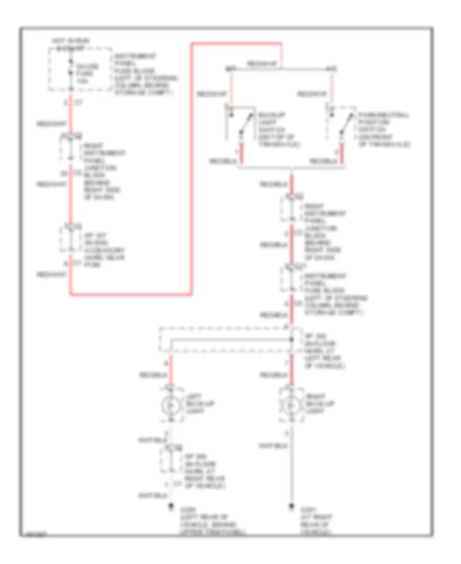
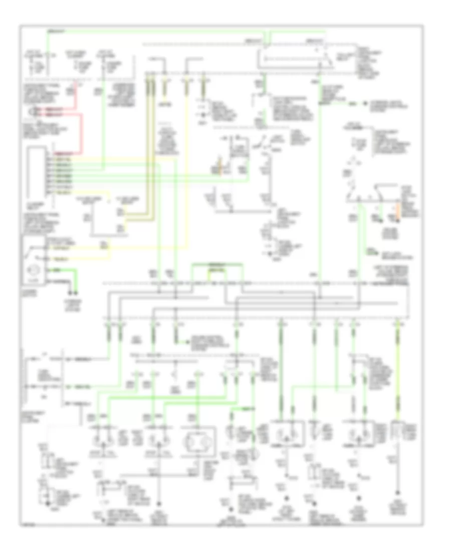
EXTERIOR LIGHTS Back-up Lamps Wiring Diagram for Pontiac Vibe GT 2003 List of elements for Back-up Lamps Wiring Diagram for Pontiac Vibe GT 2003: 16 A/t Backup light switch (on top of transaxle) C11 G300 (left rear of vehicle, behind upper trim panel) G301 (at right rear of vehicle) Gauge fuse 10a Hot in run & start Instrument panel fuse block (left of steering column, behind storage compt) Left back-up light M/t Park/neutral position switch (on front of transaxle) Right back-up light Right instrument panel junction block (behind right side of dash) Sp 107 (in eng accessory harn, near pcm) Sp 300 (in floor harn, at right rear of vehicle) Sp 302 (in floor harn, at left rear of vehicle) Exterior Lamps Wiring Diagram for Pontiac Vibe GT 2003 List of elements for Exterior Lamps Wiring Diagram for Pontiac Vibe GT 2003: 65 (in i/p harn, near a/c power recepticle) s202 (left of steering column, behind storage compt) fuse block instrument panel (left rear of vehicle, behind upper trim panel) g300 (not used) (pins 2,3,5,6,7 & 10 not used) Anti-lock brakes system C11 C12 Center high mount stop lamp Cruise control system Cruise control, shift interlock & engine controls system Daytime running lamp (drl) control module (behind right side of steering column, above brake pedal) Flasher relay G102 (on right inner fender) G103 (at left front strut tower) G200 G201 G300 (bottom of left "c" pillar) G300 (left rear of vehicle, behind upper trim panel) G301 (at right rear of vehicle) Gauge fuse 10a Hazard fuse 10a Hazard switch Head Hot at all times Hot in run & start Illum Instrument panel cluster Instrument panel fuse block (left of steering column, behind storage compt) Interior lights & engine controls system Interior lights system Left front park/ turn lamp Left instrument panel junction block Left license plate lamp Left rear turn lamp Left tail/ stop lamp Light switch Multi- function alarm module (mounted to dash fuse block) Off Right front park/ turn lamp Right instrument panel junction block (behind right side of dash) Right license plate lamp Right rear turn lamp Right tail/ stop lamp S102 S103 S401 Sp 100 (in eng main harn, located on underside of under hood fuse block) Sp 200 (under left side of dash) Sp 201 (behind right body hinge pillar trim panel) Sp 300 (in floor harn, at right rear of vehicle) Sp 400 (in back door no2 harn, behind liftgate trim panel) Stop Stop fuse 15a Stop lamp switch (on brake pedal support bracket) Tail Tail fuse 15a Taillight relay Turn Turn signal indicators Turn signal switch Turn signal/ headlamp switch Underhood fuse block (left side of eng compt, mounted to inner fender) W/ keyless entry W/o keyless entry
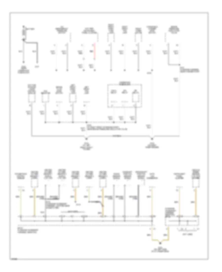
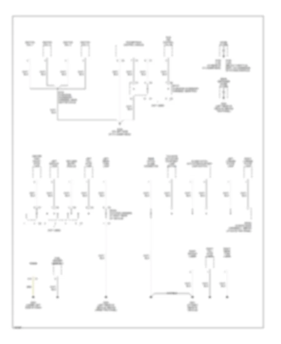
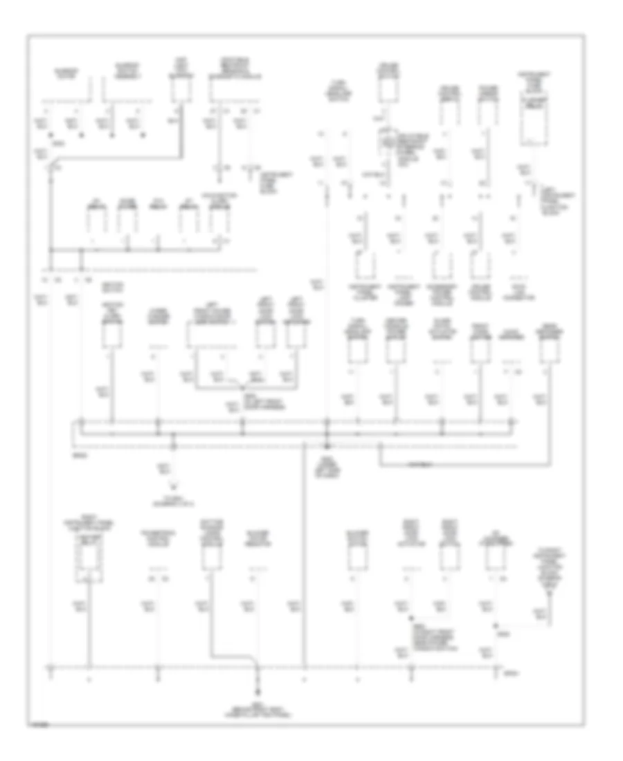
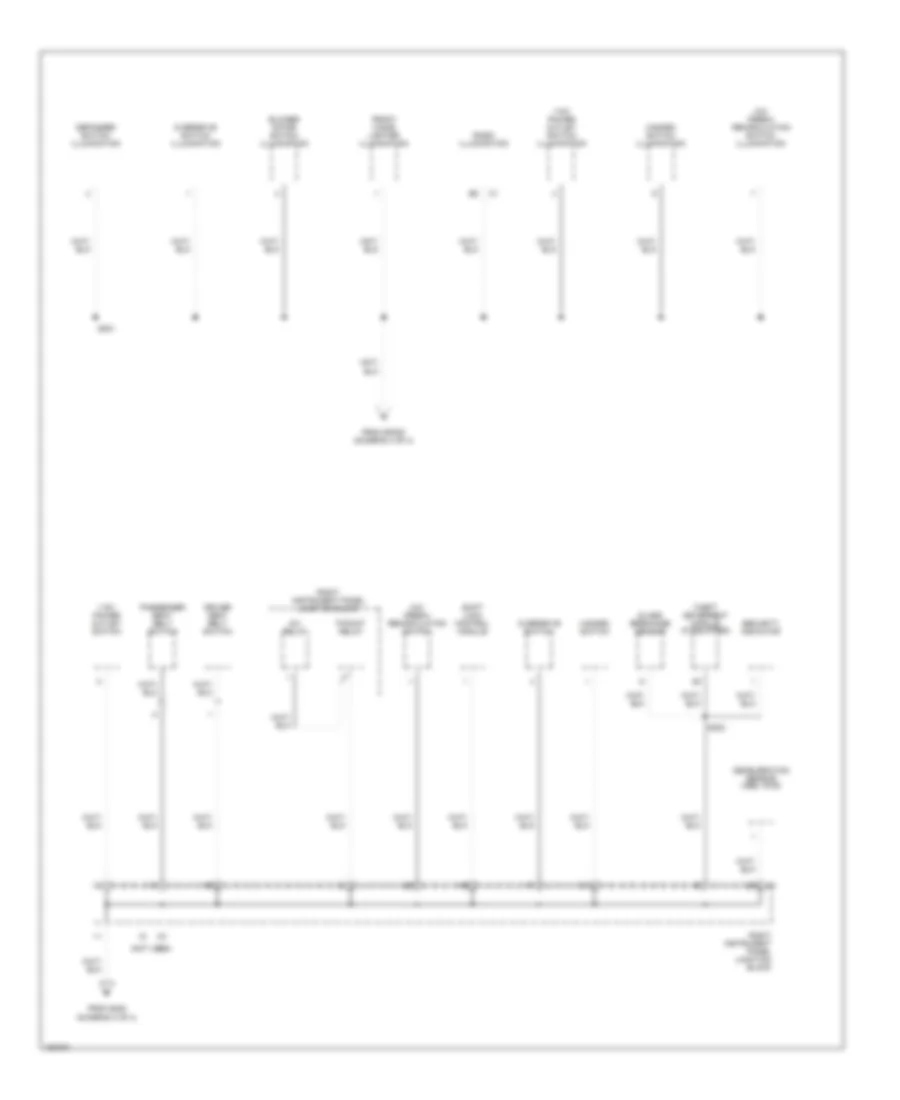
GROUND DISTRIBUTION Ground Distribution Wiring Diagram (1 of 4) for Pontiac Vibe GT 2003 List of elements for Ground Distribution Wiring Diagram (1 of 4) for Pontiac Vibe GT 2003: 46 (in engine accessory harness, near pcm) sp108 (not used) (w/o abs) instrument panel cluster A/c refrigerant pressure switch Battery Braided wire Brake fluid level switch Brake pressure modulator valve Camshaft position sensor shield Crankshaft position sensor shield Data link connector Daytime running lamps control module Dim relay Efi relay Fan 2 relay Fan resistor Front wiper motor G100 (near underhood fuse block) G101 G102 (on right inner fender) G103 (at left front strut tower) G104 (on left side of cylinder head) Heated oxygen sensor 1 (lnk) Heated oxygen sensor 1 (lv6) Heated oxygen sensor 1 shield (lv6, lnk) Heated oxygen sensor 2 (lnk) Heated oxygen sensor 2 (lv6) Heated oxygen sensor 2 shield (lv6, lnk) Instrument panel cluster Knock sensor shield Left front fog lamp Left front park/ turn lamp Nca Powertrain control module Red Right front fog lamp Right front park/ turn lamp S101 (in engine harness, near washer pump) S102 S103 (at right front of engine compt, near brake pressure modulator valve) S104 (in engine accessory harness, located near noise filter) S116 Sp107 (in engine accessory harness, near pcm) Underhood fuse block Vehicle speed sensor (lv6, 2wd w/o abs) Windshield washer level switch Ground Distribution Wiring Diagram (2 of 4) for Pontiac Vibe GT 2003 List of elements for Ground Distribution Wiring Diagram (2 of 4) for Pontiac Vibe GT 2003: 36 (not used) A12 Center high mount stop lamp Fuel sender assembly G105 (on left side of cylinder head) G106 (lnk) (below throttle body, on underside of intake manifold) G106 (lv6) (at rear of cylinder head) G202 (under left side of dash) G300 (left rear of vehicle, behind upper trim panel) G301 (at right rear of vehicle) G302 (left rear of vehicle, behind trim panel) Glass hatch actuator/courtesy lamp switch Idle air control valve Ignition coil 1 Ignition coil 2 Ignition coil 3 Ignition coil 4 Keyless entry module Left backup lamp Left license plate lamp Left rear turn lamp Left tail/ stop lamp Noise filter Powertrain control module Radio Rear defogger noise filter Rear hatch glass connector Right backup lamp Right license plate lamp Right rear turn lamp Right tail/ stop lamp S105 (in eingine accessory harness, near ignition coils) Sp107 (in engine accessory harness, near pcm) Sp300 (in floor harness, at right rear of vehicle) Sp400 (in back door harness 2, behind liftgate trim panel) Tailgate actuator/ courtesy lamp switch Ground Distribution Wiring Diagram (3 of 4) for Pontiac Vibe GT 2003 List of elements for Ground Distribution Wiring Diagram (3 of 4) for Pontiac Vibe GT 2003: 51 Accessory power control module Audio amplifier Blower motor resistor Blower switch motor Cd changer (if equipped) Center console power outlet Cruise control module Cruise control servo Cruise control switch Data link connector Daytime running lamps control module Flasher relay Front cigar lighter G200 (under left side of dash) G201 (behind right body hinge pillar trim panel) Glass hatch actuator switch Heater relay Ig1 relay Ignition key alarm switch Ignition switch Infatable restraint sensing & diagnostic module Inflatable restraint steering wheel module coil Instrument panel cluster Instrument panel fuse block Instrument panel lamp dimmer Left front door lock actuator Left front door lock switch Left front power window/door lock switch Left instrument panel junction block Malfunction alarm module Map light (w/o sunroof) Noise filter P/w relay Power mirror switch Powertrain control module Rear defogger switch Right front door lock actuator Right front door lock switch Right instrument panel junction block S222 S302 S500 (in left front door harness) Sp200 Sp201 St relay Sunroof motor Sunroof switch assembly To right instrument panel junction block (diagram 4 of 4) To s221 (diagram 4 of 4) Turn signal/ headlamp switch Wiper/ washer switch Ground Distribution Wiring Diagram (4 of 4) for Pontiac Vibe GT 2003 List of elements for Ground Distribution Wiring Diagram (4 of 4) for Pontiac Vibe GT 2003: 27 (not used) 115v power outlet switch 115v power outlet switch illumination A/c/ fresh/ recirculation switch A/c/ fresh/ recirculation switch illumination Blower motor switch illumination Deceleration sensor (abs, awd) Defogger switch illumination Driver seat belt switch From s222 (diagram 3 of 4) From sp200 (diagram 3 of 4) Front cigar lighter illumination Glass breakage sensor Hazard switch Hazard switch illumination Inv relay Overdrive switch Overdrive switch illumination P-point relay Passenger seat belt switch Radio illumination Right instrument panel junction block S221 S223 Security indicator Shift lock control module Theft deterrent module (if equipped)
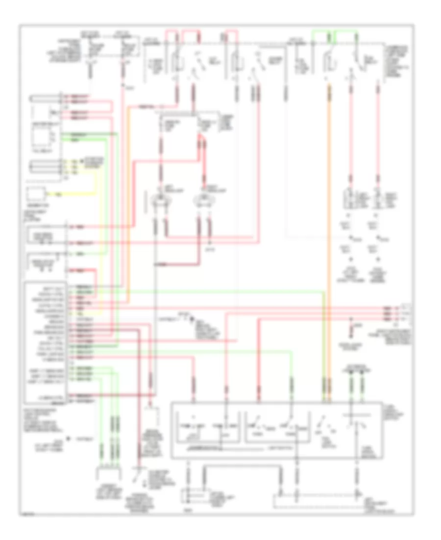
HEADLIGHTS Headlights Wiring Diagram for Pontiac Vibe GT 2003 List of elements for Headlights Wiring Diagram for Pontiac Vibe GT 2003: 77 (in center console, mounted to paking brake lever) Ambient light sensor (at top left side of dash) Ambt lt sens gnd Ambt lt sens sig Ambt lt sens volt Batt volt Brake pressure modulator valve (at right front of eng compt) Brake sig Charge in Daytime running lamp control module (at right side of steering column, above brake pedal) Dim rly ctrl Dimmer relay Dimmer switch Door locks system Ecu-b fuse 10a Exterior lights system Fog lamp switch Fog relay Fog rly ctrl Fr fog fuse 15a G102 (on right inner fender) G103 (at left front strut tower) G200 G201 (behind right body hinge pillar trim panel) Gauge fuse 10a Generator Ground Grund Head Head lh fuse 15a Head main fuse 30a Head rh fuse 15a Headlamp on ind Headlamps sig Headlap on indicator Heater relay Hi beam sig High High beam indicator Hlp relay Hlp rly ctrl Hot at all times Hot in on or start Ign volt Instrument panel cluster Instrument panel fuse block (left of steering column, behind storage compt) Left front fog lamp Left headlamp Left instrument panel junction block Light switch Lo beam ctrl Low Off Park Park brake sig Park lamp sig Parking brake switch (closed with parking brake engaged) Pass Red Right front fog lamp Right headlamp Right instrument panel junction block (behind right side of dash) S102 S103 S119 S120 S121 S205 Sp 200 (under left side of dash) Sp 201 Starting/ charging system Tail relay Tail rly ctrl Turn signal switch Turn signal/ headlamp switch Under- hood fuse block Underhood fuse block (left side of eng compt, mounted to inner fender)
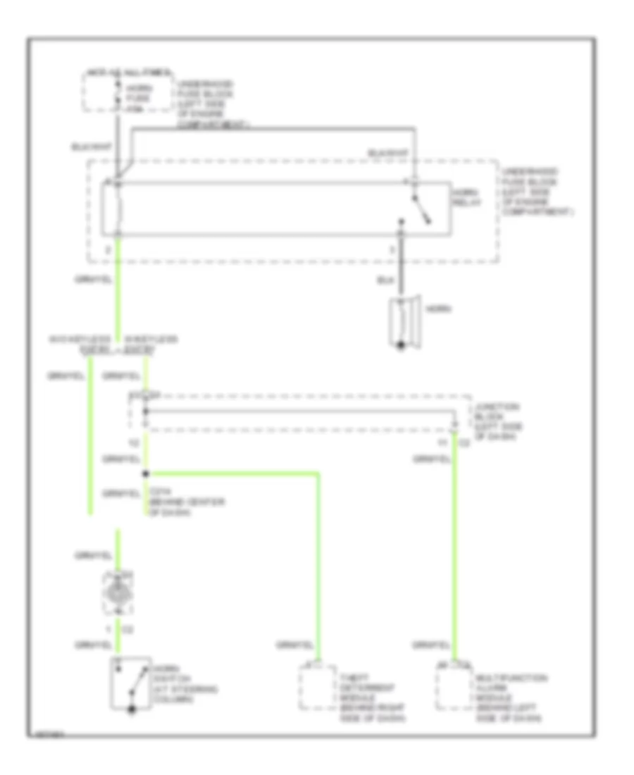
HORN Horn Wiring Diagram for Pontiac Vibe GT 2003 List of elements for Horn Wiring Diagram for Pontiac Vibe GT 2003: 12 (behind center of dash) Horn Horn fuse 10a Horn relay Horn switch (at steering column) Hot at all times Junction block (left side of dash) Multifunction alarm module (behind left side of dash) Theft deterrent module (behind right side of dash) Underhood fuse block (left side of engine compartment) W/keyless entry W/o keyless entry
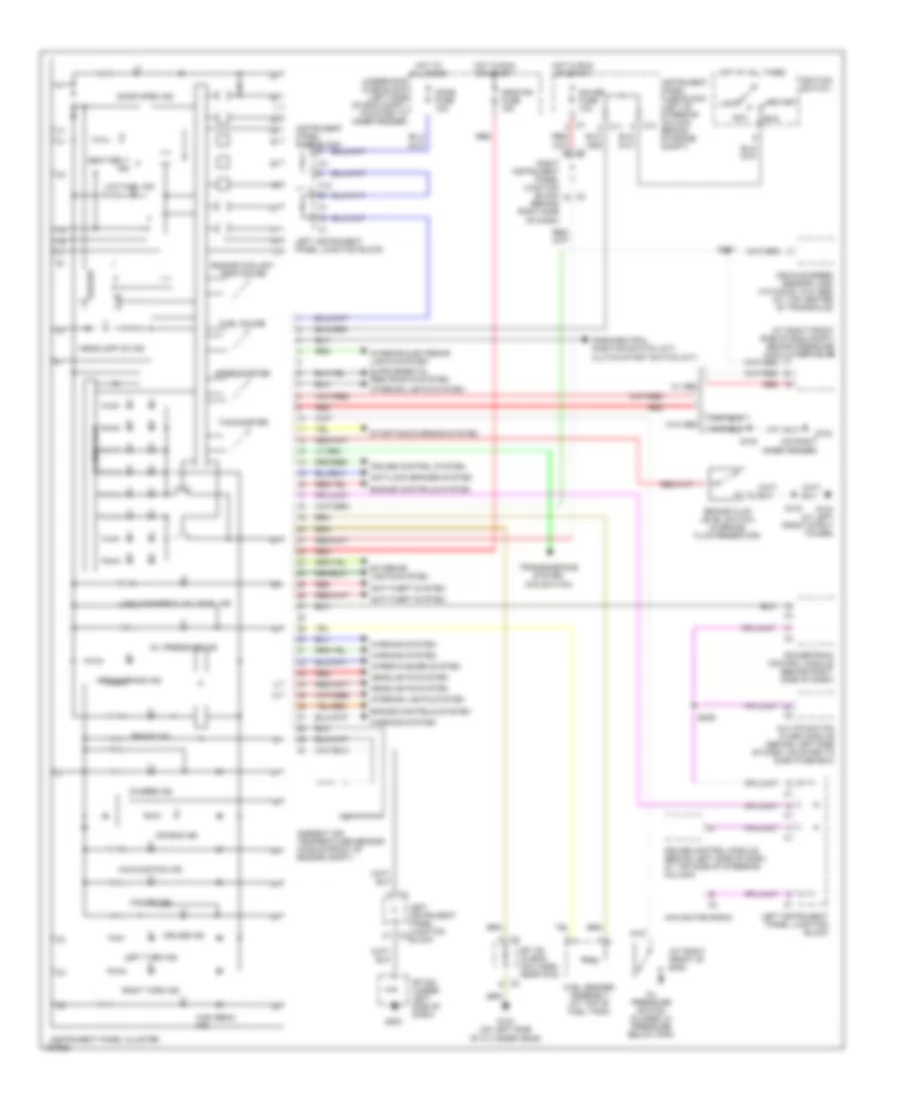
INSTRUMENT CLUSTER Instrument Cluster Wiring Diagram for Pontiac Vibe GT 2003 List of elements for Instrument Cluster Wiring Diagram for Pontiac Vibe GT 2003: 76 (at right front of eng) (at right front side of eng compt) brake pressure modulator valve Abs warning ind Acc Air bag ind Ambient air temperature sensor (middle front of engine compt) Anti-lock brakes system Anti-theft system Brake fluid level switch (in brake fluid reservoir) Brake ind Buzzer C11 C12 Charge ind Cruise control module (behind left side of dash, at top side of steering column) Cruise control system Cruise ind Dome fuse 15a Door open ind Engine controls system Engine coolant temp gauge Exterior lights system Fuel gauge Fuel sender assembly (at top of fuel tank) G102 (on right inner fender) G103 (at left front strut tower) G104 (on left side of cylinder head) G200 Gauge fuse 10a Head rh fuse 15a Headlamp on ind Headlights system High beam ind Hot at all times Hot in run or start Ignition switch Illumination Instrument panel cluster Instrument panel fuse block Instrument panel fuse block (left of steering column, behind storage compt) Interior lights system Left instrument panel junction block Left turn ind Lock Low fuel ind Low washer fluid level ind Malfunction ind Multifunction alarm module (behind left side of dash, mounted to dash fuse box) Navigation radio O/d off ind Oil pressure ind Oil pressure switch (closed w/ pressure below 3psi) Park/neutral position switch (a/t) clutch start switch (m/t) Powertrain control module (behind right side of dash) Red Right instrument panel junction block (behind right side of dash) Right turn ind Run S102 S103 S117 S206 Seat belt ind Sp 108 (in eng acc harn, near pcm) Sp 200 (under left side of dash) Speedometer Start Starting/charging system Tachometer Transmissions system (o/d switch) Underhood fuse block (left side of eng compt, mounted to inner fender) Vehicle speed sensor (vss) (vin 8/2wd, w/o abs) (at top center of transaxle) W/ abs W/o abs Warning system Wiper/washer system
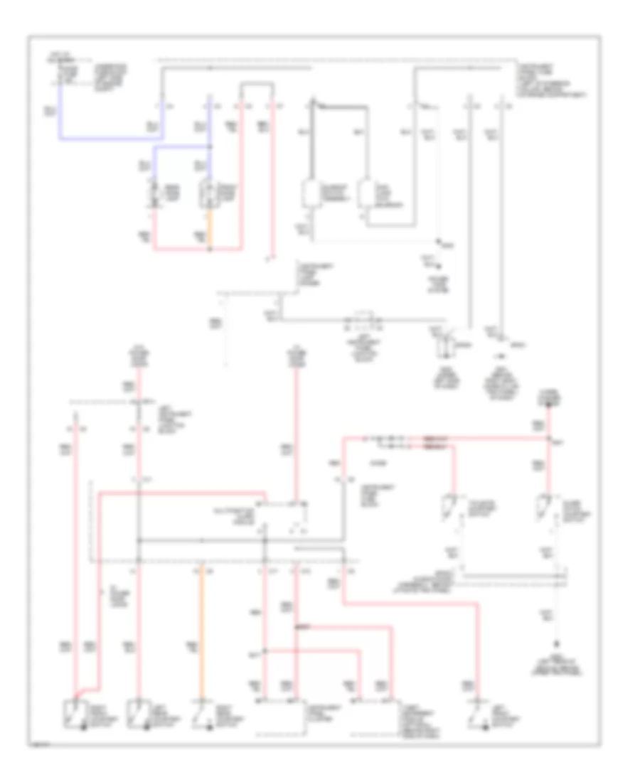
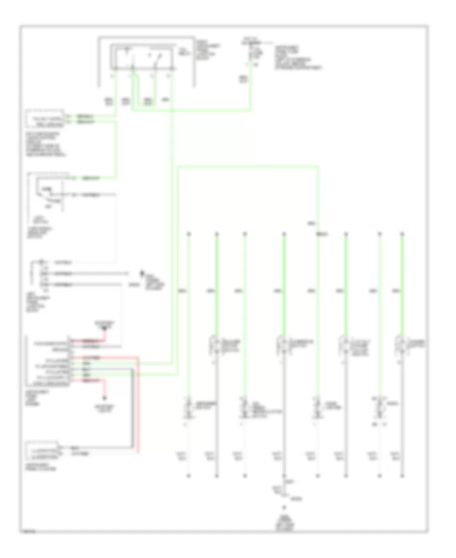
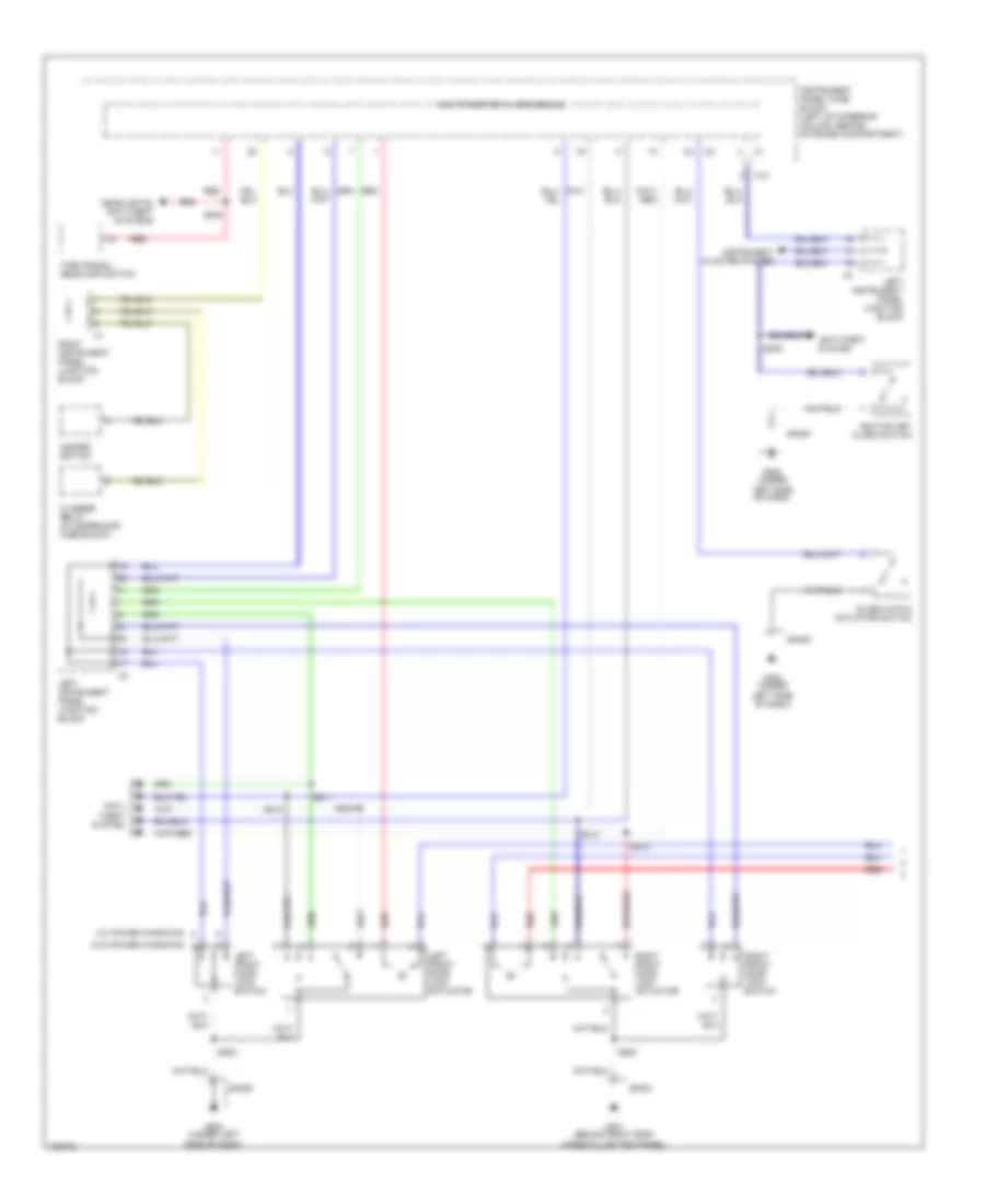
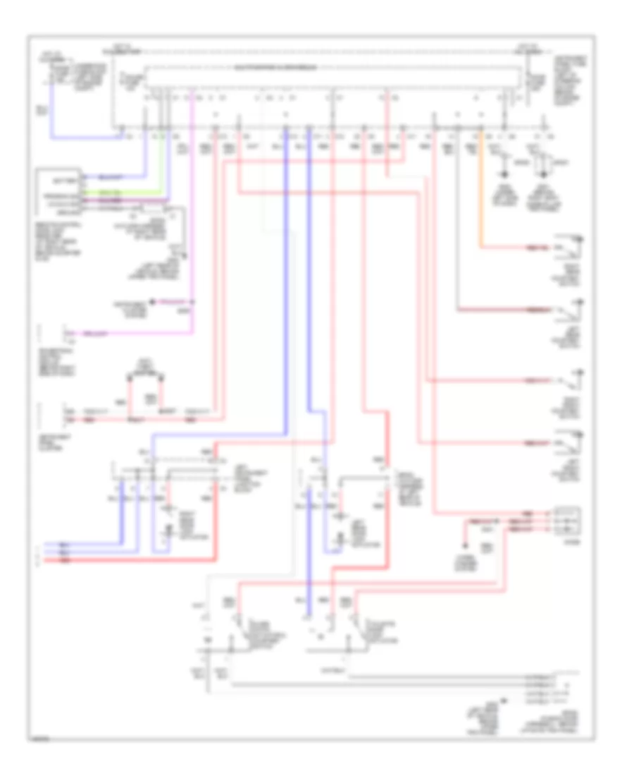
INTERIOR LIGHTS Courtesy Lamps Wiring Diagram for Pontiac Vibe GT 2003 List of elements for Courtesy Lamps Wiring Diagram for Pontiac Vibe GT 2003: 38 C11 C12 Diode Dome fuse 15a Front dome lamp G200 (under left side of dash) G201 (behind right body hinge pillar trim panel) of dash) G300 (left rear of vehicle, behind upper trim panel) Glass hatch courtesy switch Hot at all times Instrument panel cluster Instrument panel fuse block Instrument panel fuse block (left of steering column, behind storage compartment) Instrument panel lamp dimmer Left front courtesy switch Left instrument panel junction block Left rear courtesy switch Map lamp (w/o sunroof) Multifunction alarm module Power tops system Rear dome lamp Red Right front courtesy switch Right rear courtesy switch S207 S217 S302 S401 Sp200 Sp201 Sp400 (in back door harness 2, behind liftgate trim panel) Sunroof switch assembly Tailgate courtesy switch Theft deterrent module (optional) (behind right side of dash) Underhood fuse block (left side of engine compt) W/ power door locks W/o power door locks Wiper/ washer system Instrument Illumination Wiring Diagram for Pontiac Vibe GT 2003 List of elements for Instrument Illumination Wiring Diagram for Pontiac Vibe GT 2003: 35 115 volt power outlet switch A/c/ fresh/ recirculation switch Blower motor switch Cigar lighter Courtesy lights Ctsy lmps cntrl Daytime running lamps control module (at right side of steering column, above brake pedal) Defogger switch F & r dome cntrl G200 (under left side of dash) Ground Hazard switch Head Hot at all times Illumination Instrument panel cluster Instrument panel fuse block (left of steering column, behind storage compartment) Instrument panel lamp dimmer Ip cluster Ip lmp dimr feed Left instrument panel junction block Light switch Off Overdrive switch Park Prk lmps sig Radio Right instrument panel junction block S220 S221 Sp200 Tail fuse 15a Tail relay Tail rly cntrl Turn signal/ headlamp switch
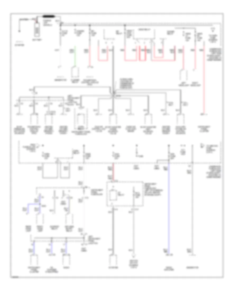
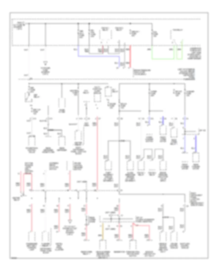
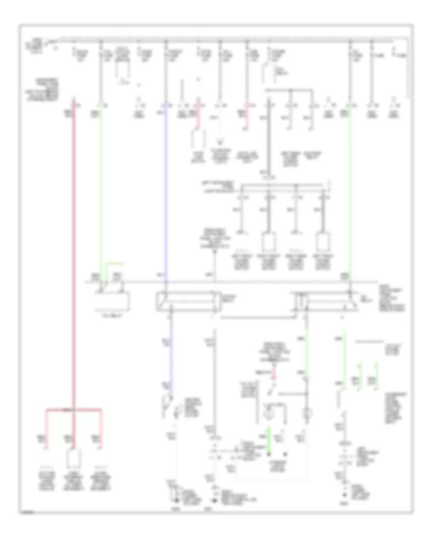
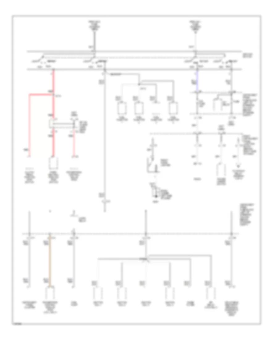
POWER DISTRIBUTION Power Distribution Wiring Diagram (1 of 4) for Pontiac Vibe GT 2003 List of elements for Power Distribution Wiring Diagram (1 of 4) for Pontiac Vibe GT 2003: 63 (diagram 1 of 4) (in eng harn, located on underside of underhood fuse block) (not used) (vin 8) (vin l) Alt fuse 100a Alt s fuse 5a Am 2 fuse 15a Amp fuse 25a Auxiliary intake air control solenoid Battery C/opn relay C13 Cd changer (if equipped) Dimmer relay Dome fuse 15a Efi fuse 15a Efi relay Evap canister purge solenoid valve Evap canister vent solenoid valve Evap pressure switching solenoid Flasher relay From fusible link a Front dome lamp Fuse Generator Hazard fuse 10a Head lh fuse 15a Head main fuse 30a Head relay Head rh fuse 15a Heated oxygen sensor (ho2s1) Heated oxygen sensor 1 (ho2s1) Heated oxygen sensor 2 (ho2s2) Horn fuse 10a Horn relay Idle air control (iac) valve Ignition switch (diagram 4 of 4) Instrument panel cluster Instrument panel fuse block Instrument panel fuse block (left of steering column, behind storage compt) Keyless entry relay Left headlamp Left instrument panel junction Left instrument panel junction block Main fuse 30a Mass air flow (maf) sensr Nca Powertrain control module (pcm) Radio Radio amplifier Rear dome lamp Red Right headlamp S100 S300 St relay Starter Sunroof relay To abs no2 fuse (diagram 2 of 4) To horn fuse (diagram 1 of 4) Underhood fuse block (left side of eng compt, mounted to inner fender) Vin 8 only Vin l only Power Distribution Wiring Diagram (2 of 4) for Pontiac Vibe GT 2003 List of elements for Power Distribution Wiring Diagram (2 of 4) for Pontiac Vibe GT 2003: 65 (diagram 1 of 4) (left of steering column, behind storage compt) instrument panel fuse block (not used) Abs no 1 fuse 30a Abs no 2 fuse 40a Ac/fresh/ recir- culation switch Backup lamp switch (m/t only) Brake pessure mdulator valve (bpmv) Brake pressure modulator valve (bpmv) C12 C13 Cruise control module Cruise control release switch Daytime running lamps (drl) control mdule Decele- ration sensor (abs, awd only) Def fuse 30a Def i/up fuse 10a Def relay Ecu-ig fuse 10a Fan no 1 relay Fan no 2 relay Flasher relay Fog fuse 15a Fog relay From alt fuse b Front washer motor Front wiper motor Gauge fuse 10a Generator Glass breakage sensor (w/ theft deterent) Heater fuse 40a Heater relay Ig 1 relay Instru- ment panel cluster Instrument panel fuse block Multi- function alarm module Noise filter P/w relay Park/neutral psition (pnp) switch Passenger seat belt warning lamp Powertrain control mdule Rdi fan fuse 40a Rear defogger Rear defogger noise filter Rear washer motor Rear wiper diode Rear wiper relay 1 Red Right instrument panel junction block Right instrument panel junction block (behind right side of dash) Rr wip fuse 15a S115 S122 S302 Shiftlock control module Sp 107 (in eng accessory harn, near pcm) Sp 109 Theft deterent module (w/ theft deterent) To 115 volt power outlet switch (diagram 3 of 4) To power fuse (diagram 3 of 4) Underhood fuse block (left side of eng compt, mounted to inner fender) Vehicle speed sensor (vss) (vin8, 2wd w/o abs only) Washer fuse 15a Wiper fuse 25a Wiper/ washer switch Power Distribution Wiring Diagram (3 of 4) for Pontiac Vibe GT 2003 List of elements for Power Distribution Wiring Diagram (3 of 4) for Pontiac Vibe GT 2003: 47 (diagram 2 of 4) (not used) 115 volt power outlet 115 volt power outlet switch Accessory ac/dc power control module (under driver's seat) Am 1 fuse 25a C10 Center console rear power outlet Data link connector (dlc) Daytime running lamps control module Door fuse 25a Ecu-b fuse 10a From alt fuse d From right instrument panel junction block (diagram 2 of 4) From right instrument panel junction block (diagram 4 of 4) Fuse G200 G201 Glass breakage sensor (w/ theft deterent) Illum lamp Instrument panel fuse block (left of steering column, behind storage compt) Interior lights system Inv fuse 15a Inv relay Left front power window switch Left instrument panel junction block Left rear power window switch Multi- fuction alarm module Odb fuse 7.5a P/point fuse 15a P/point relay P/w relay Power fuse 30a Right front power window switch Right instrument panel junction block Right instrument panel junction block (behind right side of dash) Right rear power window switch S121 Sp200 (under left side of dash) Sp201 (behind right body hinge pillar trim panel) Stop fuse 10a Stop lamp switch Sun roof relay Tail fuse 15a Tail relay Theft deterent module (w/ theft deterent) To ignition switch (diagram 4 of 4) Power Distribution Wiring Diagram (4 of 4) for Pontiac Vibe GT 2003 List of elements for Power Distribution Wiring Diagram (4 of 4) for Pontiac Vibe GT 2003: 42 (not used) Acc C/opn relay C1 b2 C11 C12 Cig fuse 15a Clutch pedal position (cpp) switch Efi relay (vin 8 only) From am 1 fuse (diagram 3 of 4) From am 2 fuse (diagram 1 of 4) Front cigar lighter Fuel injector Fuel pump Fuse G200 Ig 1 relay Ignition coil 1 Ignition coil 2 Ignition coil 3 Ignition coil 4 Ignition switch Inflatable restraint sensing & diagnostic module (sdm) Instrument panel cluster Instrument panel fuse block (left of steering column, behind storage compt) Lock Noise filter Park/ neutral positon (pnp) switch Power mirror switch Powertrain control mdule (pcm) Powertrain control module (pcm) (vin l only) Radio Red Right instrument panel junction block (behind right side of dash) Run S106 S110 S114 Sp 108 (in eng harn, near pcm) Sp200 (under left side of dash) Start To p/point relay (diagram 3 of 4)
POWER DOOR LOCKS Power Door Locks Wiring Diagram (1 of 2) for Pontiac Vibe GT 2003 List of elements for Power Door Locks Wiring Diagram (1 of 2) for Pontiac Vibe GT 2003: 33 (w/ power windows) (w/o power windows) Anti- theft system Anti-theft system C10 Flasher relay (in underhood fuse block) G200 (under left side of dash) G201 (behind right body hinge pillar trim panel) Glass hatch actuator switch Hazard switch Headlights, anti-theft systems Ignition key alarm switch Instrument cluster system Instrument panel fuse block (left of steering column, behind storage compartment) Left front door lock actuator Left front door lock switch Left instrument panel junction block Multifunction alarm module Red Right front door lock actuator Right front door lock switch Right instrument panel junction block S205 S209 S210 S211 S212 S213 S500 S600 Sp200 Sp201 Turn signal/ headlamp switch Power Door Locks Wiring Diagram (2 of 2) for Pontiac Vibe GT 2003 List of elements for Power Door Locks Wiring Diagram (2 of 2) for Pontiac Vibe GT 2003: 43 Anti- theft system Battery C1 sp300 (in floor harness, at right rear of vehicle) C11 C12 Diode Dome fuse 15a Door fuse 25a G200 (under left side of dash) G201 (behind right body hinge pillar trim panel) G300 (left rear of vehicle, behind upper trim panel) Gauge fuse 10a Glass hatch actuator & courtesy switch Ground Hot at all times Hot in run or start Instrument cluster system Instrument panel cluster Instrument panel fuse block (left of steering column, behind storage compt) Left front courtesy switch Left instrument panel junction block Left rear courtesy switch Left rear door lock actuator Lk/unlk sig Multifunction alarm module Powertrain control module (behind right side of dash) Program sig Red Remote control door lock receiver (at right rear of vehicle, behind quarter glas Right front courtesy switch Right rear courtesy switch Right rear door lock actuator S206 S207 S217 S401 Sp200 Sp201 Sp302 (in floor harness, at left rear of vehicle) Sp400 (in back door harness 2, behind liftgate trim panel) Tailgate door lock actuator Underhood fuse block (left side of engine compt) Wiper/ washer system
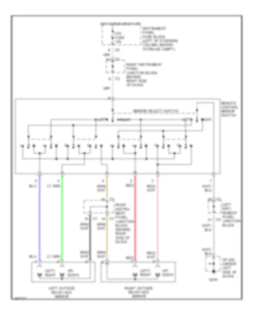
POWER MIRRORS Power Mirrors Wiring Diagram for Pontiac Vibe GT 2003 List of elements for Power Mirrors Wiring Diagram for Pontiac Vibe GT 2003: 17 Cig fuse 15a G200 Hot in run or start Instrument panel fuse block (left of steering column, behind storage compt) Left Left inst- rument panel junction block Left outside rear view mirror Left/ right Mirror select switch Red Remote control mirror switch Right Right instru- ment panel junction block (behind right side of dash) Right instrument panel junction block (behind right side of dash) Right outside rear view mirror Sp 200 (under left side of dash) Up/ down
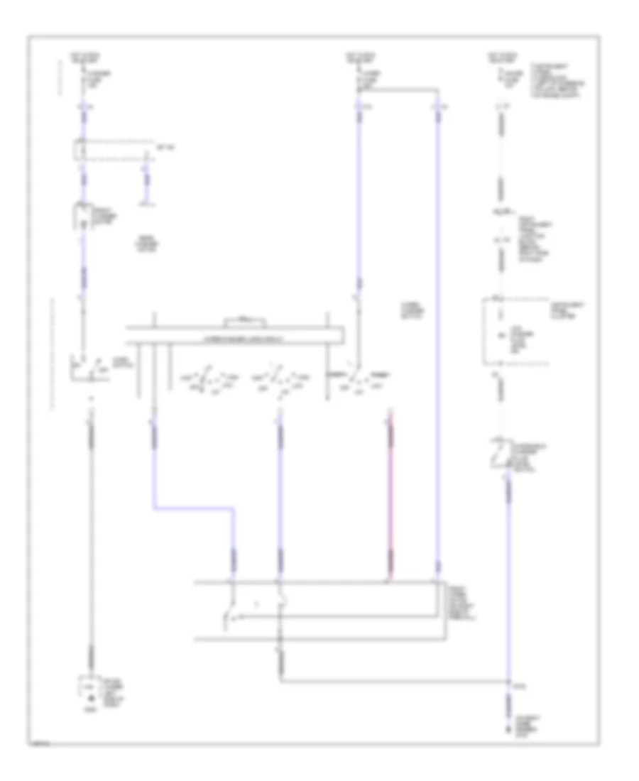
POWER TOP/SUNROOF Power Top/Sunroof Wiring Diagram for Pontiac Vibe GT 2003 List of elements for Power Top/Sunroof Wiring Diagram for Pontiac Vibe GT 2003: 24 Close Dome fuse 15a Down G200 G201 Gauge fuse 10a Hot at all times Hot in on or start Instrument panel fuse block (left of steering column, behind storage compt) Map lamps Moon roof control relay (center of windshield header) Open P/w relay Power fuse 30a Red S302 Slide Sp 200 (under left side of dash) Sp 201 (behind right body hinge pillar trim panel) Sunroof limit switch no 1 Sunroof limit switch no 2 Sunroof motor Tilt Underhood fuse block (left side of eng compt, mounted to inner fender)
POWER WINDOWS Power Windows Wiring Diagram for Pontiac Vibe GT 2003 List of elements for Power Windows Wiring Diagram for Pontiac Vibe GT 2003: 29 Door locks system Down Down or down/ auto G200 G201 Gauge fuse 10a Hot at all times Hot in on or start Instrument panel fuse block (left of steering column, behind storage compt) Left front door switch Left front window motor Left front window switch Left instru- ment panel junction block Left rear window motor Left rear window switch Lock P/w relay Power fuse 30a Red Right rear window switch Right front window motor Right front window switch Right rear window motor Right rear window switch S500 Sp 200 (under left side of dash) Sp 201 (behind right body hinge pillar trim panel) Unlock Window lock switch
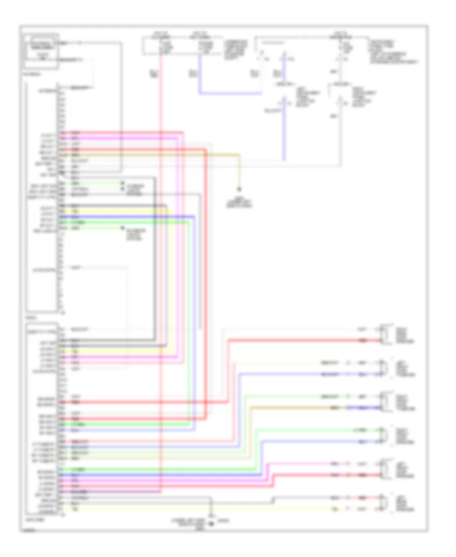
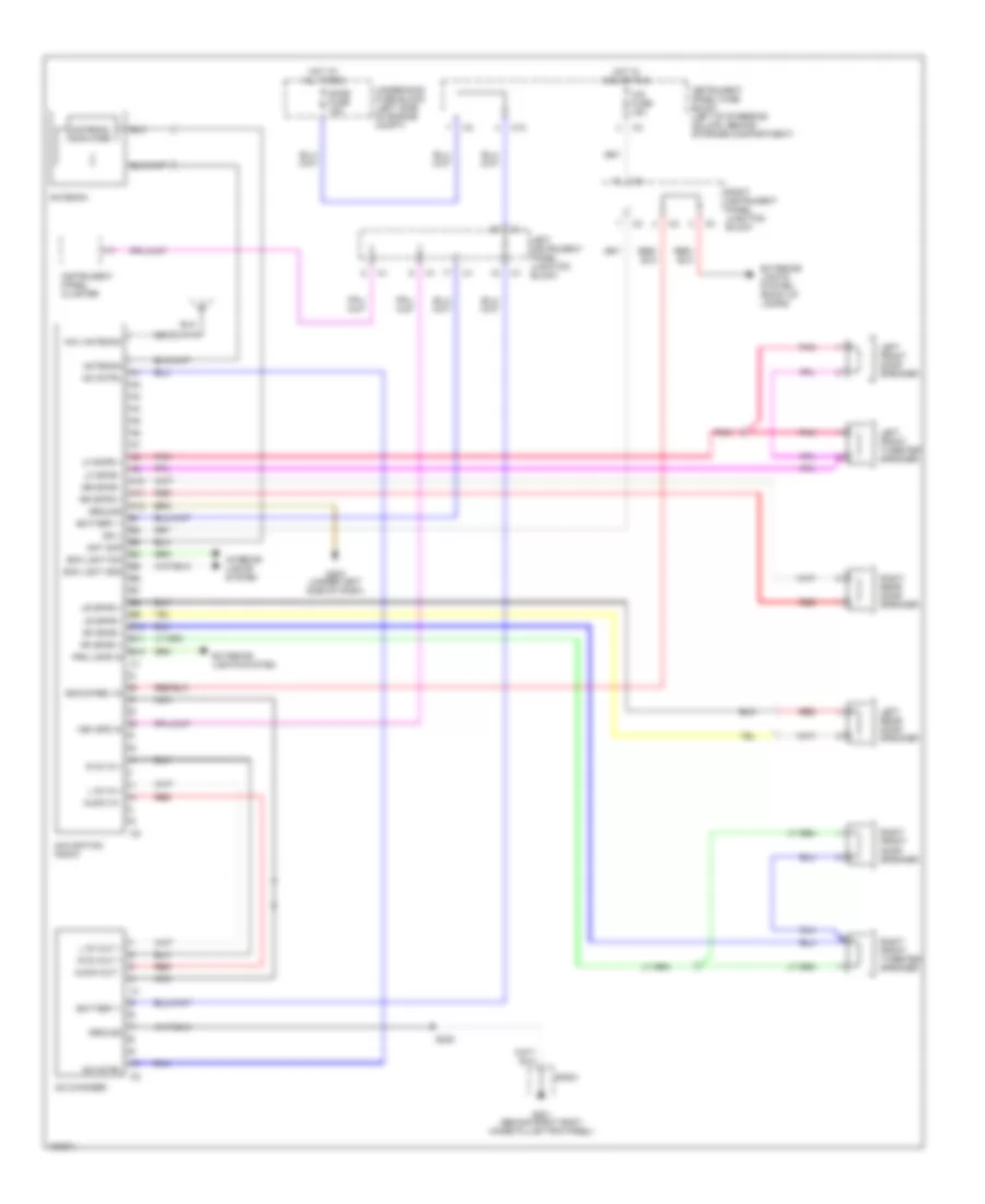
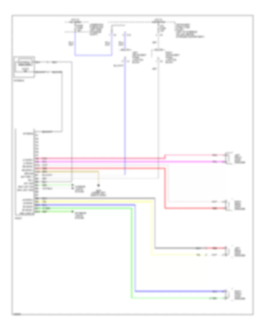
RADIO Radio Wiring Diagram, with Amplifier for Pontiac Vibe GT 2003 List of elements for Radio Wiring Diagram, with Amplifier for Pontiac Vibe GT 2003: 66 (under left side side of dash) g200 A10 A11 A12 Amp fuse 25a Amplifier Ant amp Antenna Antenna amplifier B10 B11 B12 Battery + Bck lght dim Bck lght gnd C12 Cig fuse 15a Dome fuse 15a Exterior lights system G202 (under left side of dash) Ground Hot at all times Hot in acc or run Ign + Instrument panel fuse block (left of steering column, behind storage compartment) Interior lights system Left front door speaker Left front door tweeter Left instrument panel junction block Left rear door speaker Lf input Lf out + Lf out - Lf spkr + Lf spkr - Lf tweetr + Lf tweetr - Lr input Lr out + Lr out - Lr spkr + Lr spkr - Mute cntrl Pnk Prk lmps in Radio Red Rf input Rf out + Rf out - Rf spkr + Rf spkr - Rf tweetr + Rf tweetr - Right front door speaker Right front door tweeter Right instrument panel junction block Right rear door speaker Rr input Rr out + Rr out - Rr spkr + Rr spkr - Snstvty ctrl Sp200 Underhood fuse block (left side of engine compt) Radio Wiring Diagram, with Navigation for Pontiac Vibe GT 2003 List of elements for Radio Wiring Diagram, with Navigation for Pontiac Vibe GT 2003: 61 A10 A11 A12 Ant amp Antenna Antenna amplifier Audio in - Audio out - B10 B11 B12 Battery + Bck lght dim Bck lght gnd Bckup/rev in C12 Cd changer Cd cntrl Cig fuse 15a Dome fuse 15a Exterior lights system Exterior lights system (back up lamps) G201 (behind right body hinge pillar trim panel) G202 (under left side of dash) Ground Hot at all times Hot in acc or run Ign + Instrument panel cluster Instrument panel fuse block (left of steering column, behind storage compartment) Interior lights system L ch in + L ch out + Left front door speaker Left front tweeter speaker Left instrument panel junction block Left rear door speaker Lf skpr + Lf spkr - Lr spkr + Lr spkr - Nav antenna Navigation radio Nca Pnk Prk lmps in R ch in + R ch out + Red Rf spkr + Rf spkr - Right front door speaker Right front tweeter speaker Right instrument panel junction block Right rear door speaker Rr spkr + Rr spkr - S222 Sp201 Underhood fuse block (left side of engine compt) Veh spd in Radio Wiring Diagram, without Amplifier for Pontiac Vibe GT 2003 List of elements for Radio Wiring Diagram, without Amplifier for Pontiac Vibe GT 2003: 42 A10 A11 A12 Ant amp Antenna Antenna amplifier B10 B11 B12 Battery + Bck lght dim Bck lght gnd C12 Cig fuse 15a Dome fuse 15a Exterior lights system G202 (under left side of dash) Ground Hot at all times Hot in acc or run Ign + Instrument panel fuse block (left of steering column, behind storage compartment) Interior lights system Left front door speaker Left instrument panel junction block Left rear door speaker Lf skpr + Lf spkr - Lr spkr + Lr spkr - Pnk Prk lmps in Radio Red Rf spkr + Rf spkr - Right front door speaker Right instrument panel junction block Right rear door speaker Rr spkr + Rr spkr - Underhood fuse block (left side of engine compt)
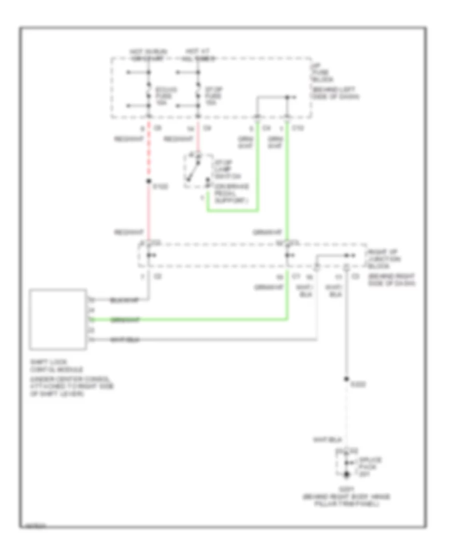
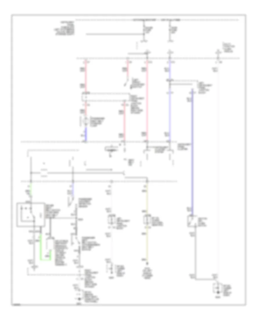
SHIFT INTERLOCK Shift Interlock Wiring Diagram for Pontiac Vibe GT 2003 List of elements for Shift Interlock Wiring Diagram for Pontiac Vibe GT 2003: 17 (behind left side of dash) (behind right side of dash) (on brake pedal support) (under center consol, attached to right side of shift lever) C12 Ecu-ig fuse 10a G201 (behind right body hinge pillar trim panel) Hot at all times Hot in run or start I/p fuse block Right i/p junction block S122 S222 Shift lock contol module Splice pack Stop fuse 15a Stop lamp switch
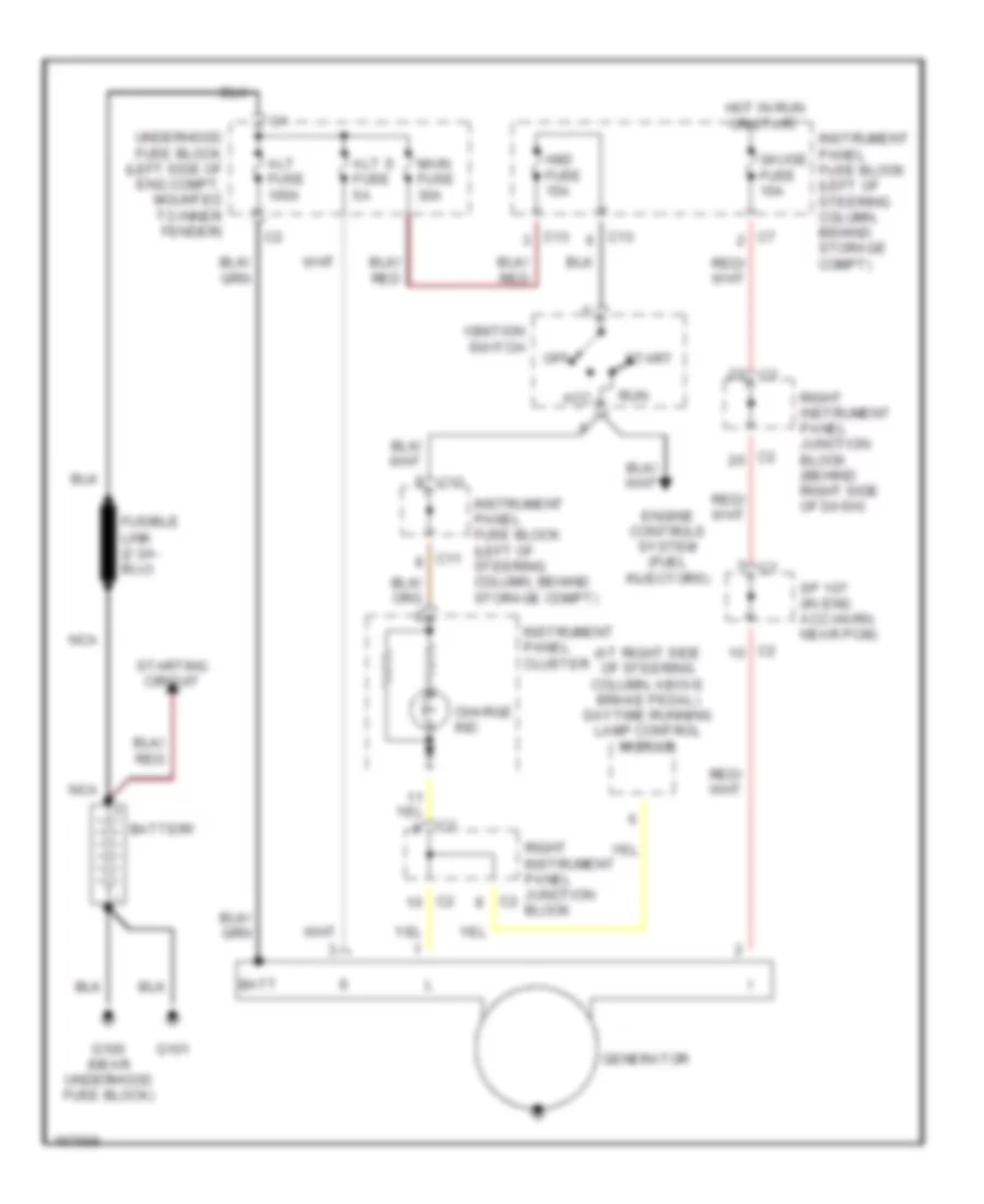
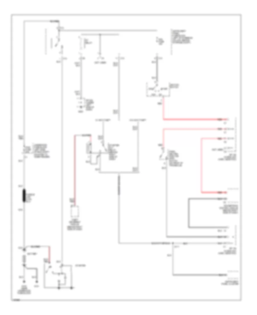
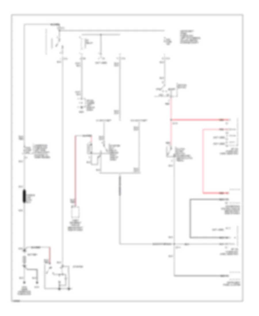
STARTING/CHARGING Charging Wiring Diagram for Pontiac Vibe GT 2003 List of elements for Charging Wiring Diagram for Pontiac Vibe GT 2003: 30 (at right side of steering column, above brake pedal) daytime running lamp control module Acc Alt fuse 100a Alt s fuse 5a Am2 fuse 15a Batt Battery C11 C12 C13 Charge ind Engine controls system (fuel injectors) G100 (near underhood fuse block) G101 Gauge fuse 10a Generator Hot in run or start Ignition switch Instrument panel cluster Instrument panel fuse block (left of steering column, behind storage compt) Main fuse 30a Nca Off Right instrument panel junction block (behind right side of dash) Right instrument panel junction c2 block Run Sp 107 (in eng acc harn, near pcm) Start Starting circuit Underhood fuse block (left side of eng compt, mounted to inner fender) Starting Wiring Diagram, A/T for Pontiac Vibe GT 2003 List of elements for Starting Wiring Diagram, A/T for Pontiac Vibe GT 2003: 29 (not used) Acc Am2 fuse 15a Battery C12 C13 G100 (near underhood fuse block) G101 G200 Ignition switch Instrument panel cluster Instrument panel fuse block (left of steering column, behind storage compt) Main fuse 30a Nca Off Park/ neutral position (pnp) switch (on front of transaxle) Powertrain comtrol module (behind right side of dash) Red S111 Sp 108 (in eng acc harn, near pcm) Sp 200 (under left side of dash) St relay Start Starter Starter cut relay (behind right side of dash) Theft deterent module (behind right side of dash) Underhood fuse block (left side of eng compt, mounted to inner fender) W/ anti-theft W/o anti-theft Starting Wiring Diagram, M/T for Pontiac Vibe GT 2003 List of elements for Starting Wiring Diagram, M/T for Pontiac Vibe GT 2003: 30 (not used) Acc Am2 fuse 15a Battery C12 C13 Clutch start switch (on bracket, above clutch pedal) G100 (near underhood fuse block) G101 G200 Ignition switch Instrument panel cluster Instrument panel fuse block (left of steering column, behind storage compt) Main fuse 30a Nca Off Powertrain comtrol module (behind right side of dash) Red S110 S111 Sp 108 (in eng acc harn, near pcm) Sp 200 (under left side of dash) St relay Start Starter Starter cut relay (behind right side of dash) Theft deterent module (behind right side of dash) Underhood fuse block (left side of eng compt, mounted to inner fender) W/ anti-theft W/o anti-theft
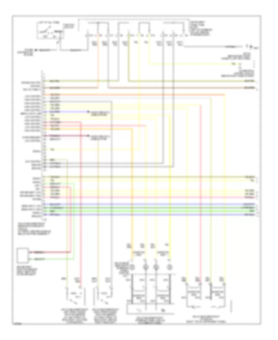
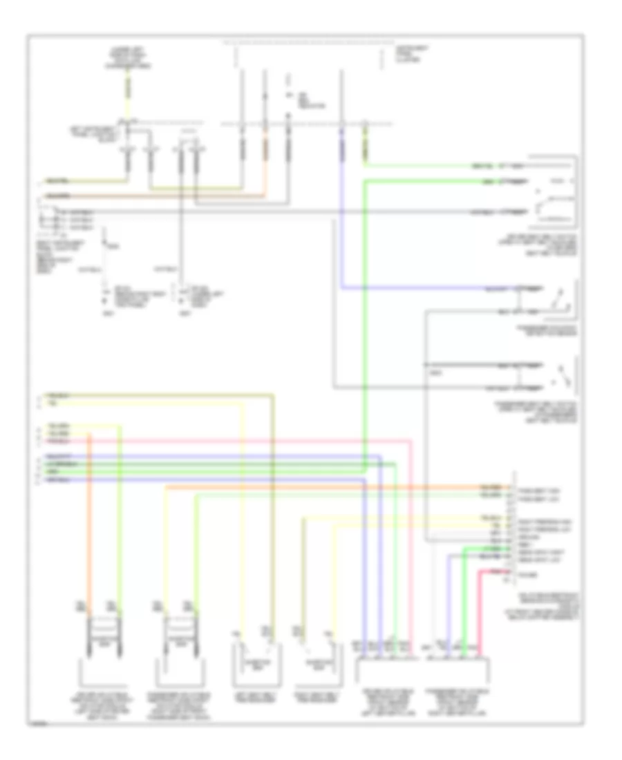
SUPPLEMENTAL RESTRAINTS Supplemental Restraints Wiring Diagram (1 of 2) for Pontiac Vibe GT 2003 List of elements for Supplemental Restraints Wiring Diagram (1 of 2) for Pontiac Vibe GT 2003: 39 Acc Air bag ind ctrl C10 C11 C12 Computer data lines system Control Diagn request Driver seat high Driver seat low Driver seat position sensor (right seat rail of driver seat) G201 Ground High control Hot at all times Ignition switch Inflatable restraint i/p module (right top of instrument panel) Inflatable restraint left front discri- minating sensor (at left front of eng compt, mounted to frame rail) Inflatable restraint right front discri- minating sensor (at right front of eng compt, behind right headlight) Inflatable restraint sensing & diagnostic module (at front center console, below shifter assembly) Inflatable restraint steering wheel module (in steering wheel) Inflatable restraint steering wheel module coil Ing voltage (+) Instrument panel fuse block (left of steering column, behind storage compt) Lock Low control Lsp + Lsp - Nca Power Power distribution system Powertrain control module (behind right side of dash) Sens input high Sens input low Serial data line Shorting bar Signal Sp 201 (behind right body hinge pillar trim panel) Start Supplemental Restraints Wiring Diagram (2 of 2) for Pontiac Vibe GT 2003 List of elements for Supplemental Restraints Wiring Diagram (2 of 2) for Pontiac Vibe GT 2003: 32 (under left side of dash) data link connector obd2 Air bag indicator Driver inflatable restraint side impact inflator module (left side of driver seat back) Driver inflatable restraint side impact sensor (at bottom of left center pillar) Driver seat belt switch (open w/ seat belt buckled) (in driver's seat belt buckle) G201 Ground Inflatable restraint sensing & diagnostic module (at front center console, below shifter assembly) Instrument panel cluster Left instrument panel junction block Left seat belt pretensioner Nca Pass seat high Pass seat low Passenger inflatable restraint side impact inflator module (right side of front passenger seat back) Passenger inflatable restraint side impact sensor (at bottom of right center pillar) Passenger occupant detection sensor Passenger seat belt switch (open w/ seat belt buckled) (in passenger's seat belt buckle) Pnk Power Rbe + Right instrument panel junction block (behind right side of dash) Right pretens high Right pretens low Right seat belt pretensioner S222 S223 Sens input hight Sens input low Shorting bar Sp 200 (under left side of dash) Sp 201 (behind right body hinge pillar trim panel)
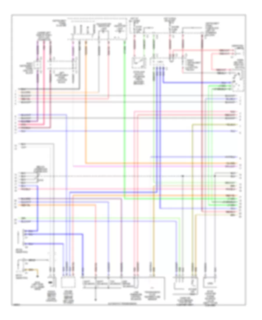
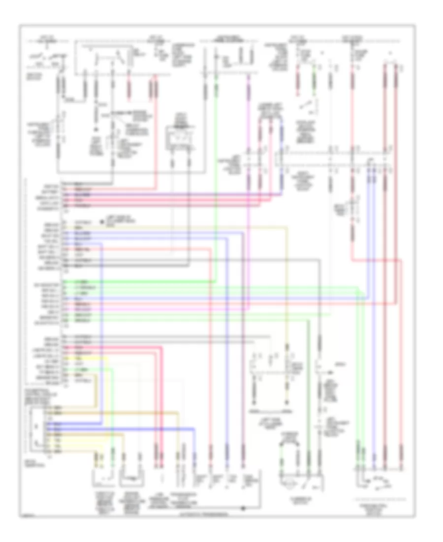
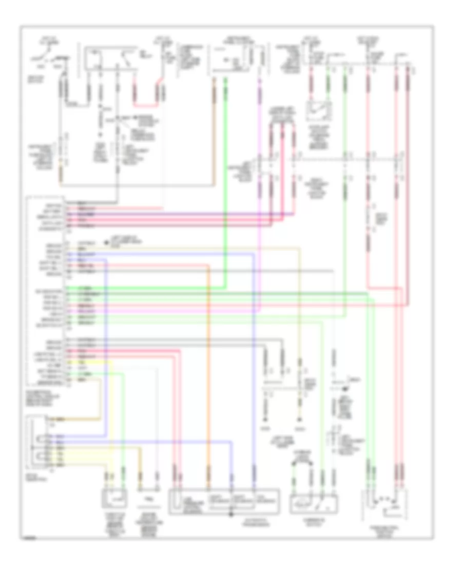
TRANSMISSION A/T Wiring Diagram, AWD for Pontiac Vibe GT 2003 List of elements for A/T Wiring Diagram, AWD for Pontiac Vibe GT 2003: 79 (below underhood fuse block) (left side (left side of cylinder head) g105 (under left side of dash) data link connector +5v ref 2nd brake sol Acc Automatic transmission Battery Brake sw C11 C12 Data link Diagnostic Ect sens in Efi fuse 15a Efi relay Engine controls system Engine coolant temperature sensor (rear of engine) G103 (left front strut tower) G104 G105 G201 (behind right body hinge pillar) Gauge fuse 10a Ground Hot at all times Hot in run or start Ignition Ignition switch Input shaft speed sensor Instrument panel cluster Instrument panel fuse block (left of steering column) Interior lights system Iss sens hi Iss sens lo Left instrument panel junction block Left instrument panel junction c2 block Left instrument panel junction c3 block Line pc sol hi Line pc sol lo Line pressure control solenoid Lock O/d ind lamp Od indicator Od switch in Of cylinder head) Overdrive switch Park/neutral position switch Pnk Pnp sw 2 Pnp sw d Pnp sw l Pnp sw r Powertrain control module (behind right side of dash) Right instrument panel junction block Run S100 S103 S106 Sensor gnd Serial data Shift sol Shift sol 1 Shift sol 2 Sp107 (near pcm) Sp108 (near pcm) Sp201 Ss st sol Start Stop fuse 15a Stoplamp switch (on brake pedal support bracket) Tcc sol Tft sig Throttle position sensor (rear of throttle body) Tp sens in Transmission fluid temperature sensor Underhood fuse block (left side of engine compt) Vs out Vss in A/T Wiring Diagram, FWD for Pontiac Vibe GT 2003 List of elements for A/T Wiring Diagram, FWD for Pontiac Vibe GT 2003: 72 (below underhood fuse block) (left side (left side of cylinder head) g105 (under left side of dash) data link connector +5v ref Acc Automatic transmission Battery Brake sw C11 C12 Data link Diagnostic Ect sens in Efi fuse 15a Efi relay Engine controls system Engine coolant temperature sensor (rear of engine) G103 (left front strut tower) G104 G105 G201 (behind right body hinge pillar) Gauge fuse 10a Ground Hot at all times Hot in run or start Ignition Ignition switch Instrument panel cluster Instrument panel fuse block (left of steering column) Interior lights system Left instrument panel junction block Left instrument panel junction c2 block Left instrument panel junction c3 block Line pc sol hi Line pc sol lo Line pressure control solenoid Lock O/d ind lamp Od indicator Od switch in Of cylinder head) Overdrive switch Park/neutral position switch Pnk Pnp sw 2 Pnp sw l Pnp sw r Powertrain control module (behind right side of dash) Right instrument panel junction block Run S100 S103 S106 Sensor gnd Serial data Shift sol 1 Shift sol 2 Shift solenoid Sp107 (near pcm) Sp108 (near pcm) Sp201 Start Stop fuse 15a Stoplamp switch (on brake pedal support bracket) Tcc sol Tcc solenoid Throttle position sensor (rear of throttle body) Tp sens in Underhood fuse block (left side of engine compt) Vs out Vss in
WARNING SYSTEMS Warning Systems Wiring Diagram for Pontiac Vibe GT 2003 List of elements for Warning Systems Wiring Diagram for Pontiac Vibe GT 2003: 29 Buzzer C10 C12 Door fuse 25a Driver seat belt switch (in driver's seat belt buckle) G104 (on left side of cylinder head) G200 G201 Gauge fuse 10a Hot at all times Hot in run or start Ignition key alarm switch Inflatable restraint sensing & diagnostic module (at front center console, below shifter assembly) Instrument cluster system Instrument panel cluster Instrument panel fuse block (left of steering column, behind storage compt) Left front courtesy switch Left instrument panel junction block Multi- function alarm module Nca Passenger occupent detection sensor Passenger seat belt switch (in passenger's seat belt buckle) Passenger seat belt warning lamp Right instrument panel junction block (behind right side of dash) S223 Seat belt ind Sp 108 (in eng acc harn, near pcm) Sp 200 (under left side of dash) Sp 201 (behind right body hinge pillar trim panel)
WIPER/WASHER Front Wiper/Washer Wiring Diagram for Pontiac Vibe GT 2003 List of elements for Front Wiper/Washer Wiring Diagram for Pontiac Vibe GT 2003: 26 (on right inner fender) g102 C12 Front washer motor Front wiper motor (on right side of firewall) G200 Gauge fuse 10a High Hot in run or start Instrument panel cluster Instrument panel fuse block (left of steering column, behind storage compt) Int Low Low washer fluid level ind Mist Off Rear washer motor Right instrument panel junction block (behind right side of dash) S102 Sp 109 Sp 200 (under left side of dash) Wash switch Washer fuse 15a Windshield washer fluid level switch Wiper fuse 25a Wiper/ washer switch Wiper/washer logig circuit Rear Washer/Wiper Wiring Diagram for Pontiac Vibe GT 2003 List of elements for Rear Washer/Wiper Wiring Diagram for Pontiac Vibe GT 2003: 32 Defogger system Front washer motor G200 G300 (left rear of vehicle, behind upper trim panel) Gauge fuse 10a Glass hatch courtessy switch Hot in run or start Instrument panel fuse block (left of steering column, behind storage compt) Int Interior lights system Off On int Park Rear hatch class connector Rear washer motor Rear wiper diode Rear wiper motor (attached to rear liftgate glass) Rear wiper relay 1 (left of steering column, behind i/p lamp dimmer) Rear wiper relay 2 (attached to rear liftgate, behind trim panel) Right instrument panel junction block (behind right side of dash) Rr wip fuse 15a Run S400 S401 Sp 109 Sp 200 (under left side of dash) Sp 302 Sp 400 (in back door no 2 harn, behind liftgate trim panel) Wash Washer fuse 15a Wipe/wash Wiper/ washer switch