Разделы схем — 31 (всего 69)
ACTIVE BODYWORKS AIR CONDITIONING ANTI-LOCK BRAKES ANTI-THEFT COMPUTER DATA LINES COOLING FAN CRUISE CONTROL DEFOGGERS ELECTRONIC MUFFLER ENGINE PERFORMANCE EXTERIOR LIGHTS GROUND DISTRIBUTION HEADLIGHTS HORN INSTRUMENT CLUSTER INTERIOR LIGHTS MEMORY SYSTEMS NAVIGATION POWER DISTRIBUTION POWER DOOR LOCKS POWER MIRRORS POWER SEATS POWER TOP/SUNROOF POWER WINDOWS RADIO SHIFT INTERLOCK STARTING/CHARGING SUPPLEMENTAL RESTRAINTS TRANSMISSION TRUNK, TAILGATE, FUEL DOOR WIPER/WASHER
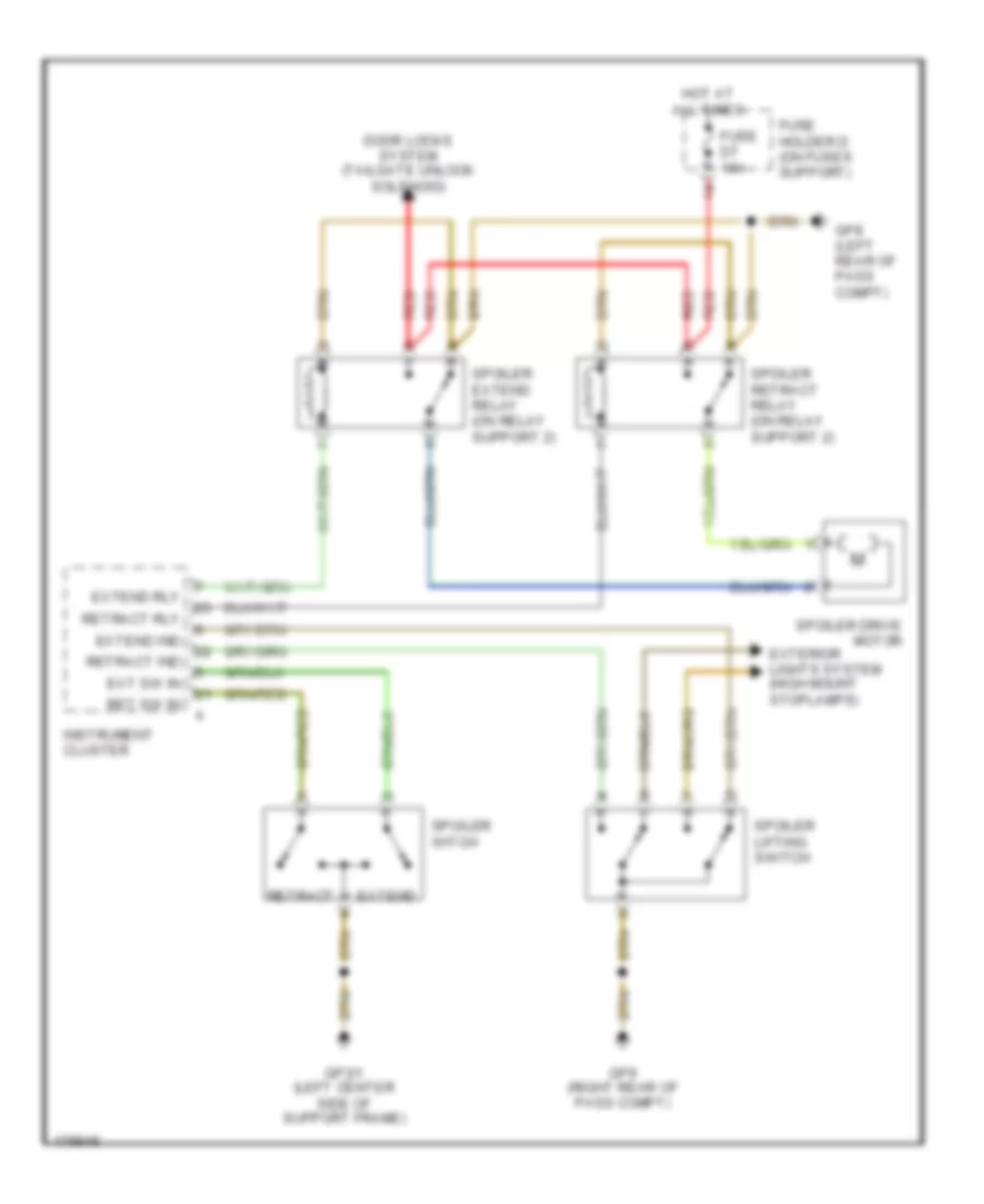
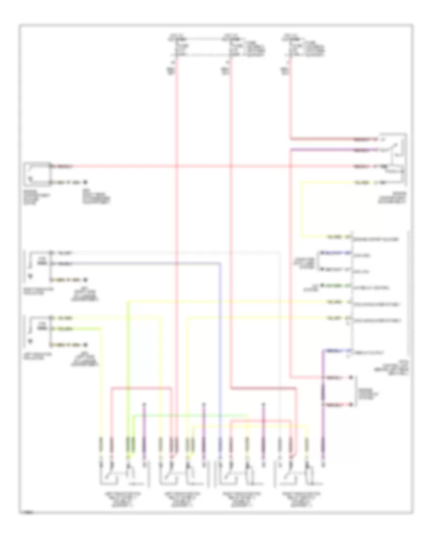
ACTIVE BODYWORKS Active Bodyworks Wiring Diagram, Early Production for Porsche 911 Turbo 2005 List of elements for Active Bodyworks Wiring Diagram, Early Production for Porsche 911 Turbo 2005: 23 Door locks system (tailgate unlock solenoid) Ext sw in Extend Extend ind Extend rly Exterior lights system (high mount stoplamps) Fuse d7 15a Fuse holder d (on fuses support) Gp3/1 (left center side of support frame) Gp8 (left rear of pass compt) Gp9 (right rear of pass compt) Hot at all times Instrument cluster Red Ret sw in Retract Retract ind Retract rly Spoiler extend relay (on relay support 2) Spoiler retract relay (on relay support 2) Spoiler drive motor Spoiler lifting switch Spoiler witch
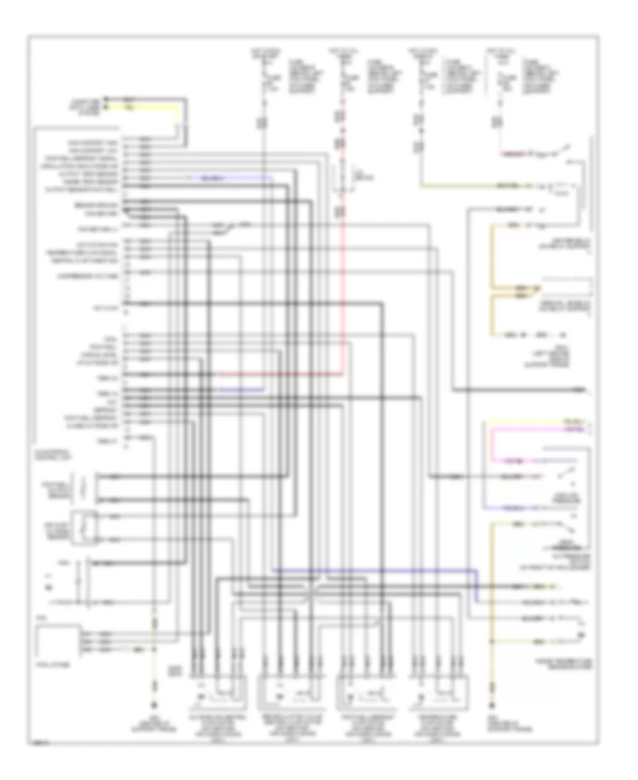
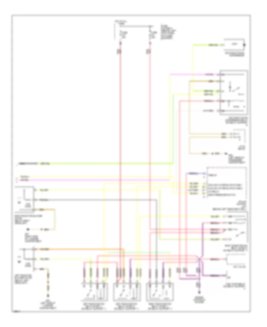
AIR CONDITIONING Automatic A/C Wiring Diagram, Early Production (1 of 2) for Porsche 911 Turbo 2005 List of elements for Automatic A/C Wiring Diagram, Early Production (1 of 2) for Porsche 911 Turbo 2005: 58 (2005) (2004) +5v/10 ma A/c pressure switch (at front of air cleaner) Actuation fan Air inlet outside sensor Can komfort high Can komfort low Central flap check sig Circulating air/outside air Climatronic control unit Close outside air Compressor voltage Computer data lines system Cool Defrost Fan Fan return Fan return (+) Final stage Footwell Footwell output sensor Footwell/defrost Footwell/defrost flap motor (on heating/ air conditioning unit) Footwell/defrost signal Fuse b1 15a Fuse c7 7.5a Fuse d6 30a Fuse e7 7.5a Fuse holder b (behind left kick panel, on fuses support) Fuse holder c (behind left kick panel, on fuses support) Fuse holder d (behind left kick panel, on fuses support) Fuse holder e (behind left kick panel, on fuses support) Gp3/1 (left center side of support frame) Gp4 (center of support frame) Heater relay (on relay support 1) High/low pressure Hot Hot at all times Hot in acc or run Hot in run or start Inside temp sensor Inside temperature sensor blower J/c (bs 9/2) Mean pressure Middle level Nca Output sensor footwell Output temp sensor Outside air central flap motor (on heating/ air conditioning unit) Recirculation valve central flap motor (on heating/ air conditioning unit) Sensor ground Temperature flap motor (on heating/ air conditioning unit) Temperature flap signal Term 15 Term 30 Term 31 Terminal xe relay (on relay support 1) Up outside air Automatic A/C Wiring Diagram, Early Production (2 of 2) for Porsche 911 Turbo 2005 List of elements for Automatic A/C Wiring Diagram, Early Production (2 of 2) for Porsche 911 Turbo 2005: 27 0.55 ohms A/c relay Aav valve Air conditioning compressor Air conditioning compressor relay (on relay support 2) Cooling water blwr stage 1 Cooling water blwr stage 2 Engine controls system Fuel pump relay (on relay support 1) Fuse c10 40a Fuse c8 40a Fuse holder c (behind left kick panel, on fuses support) Gp1 (right side of luggage compartment) Gp2 (left side of luggage compartment) Gp8 (left rear of passenger compartment) Hot at all times J/c 22 (bs 22) Left radiator blower motor (below left headlight) Left radiator fan relay (step 1) (on relay support 1) Left radiator fan relay (step 2) (on relay support 1) Mean pressure switch Mfi & di control unit (behind left rear seatwell) Nca Right radiator blower motor (below right headlight) Right radiator fan relay (step 1) (on relay support 1) Right radiator fan relay (step 2) (on relay support 1) Term 87
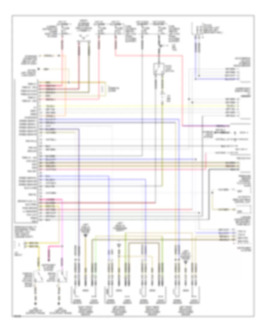
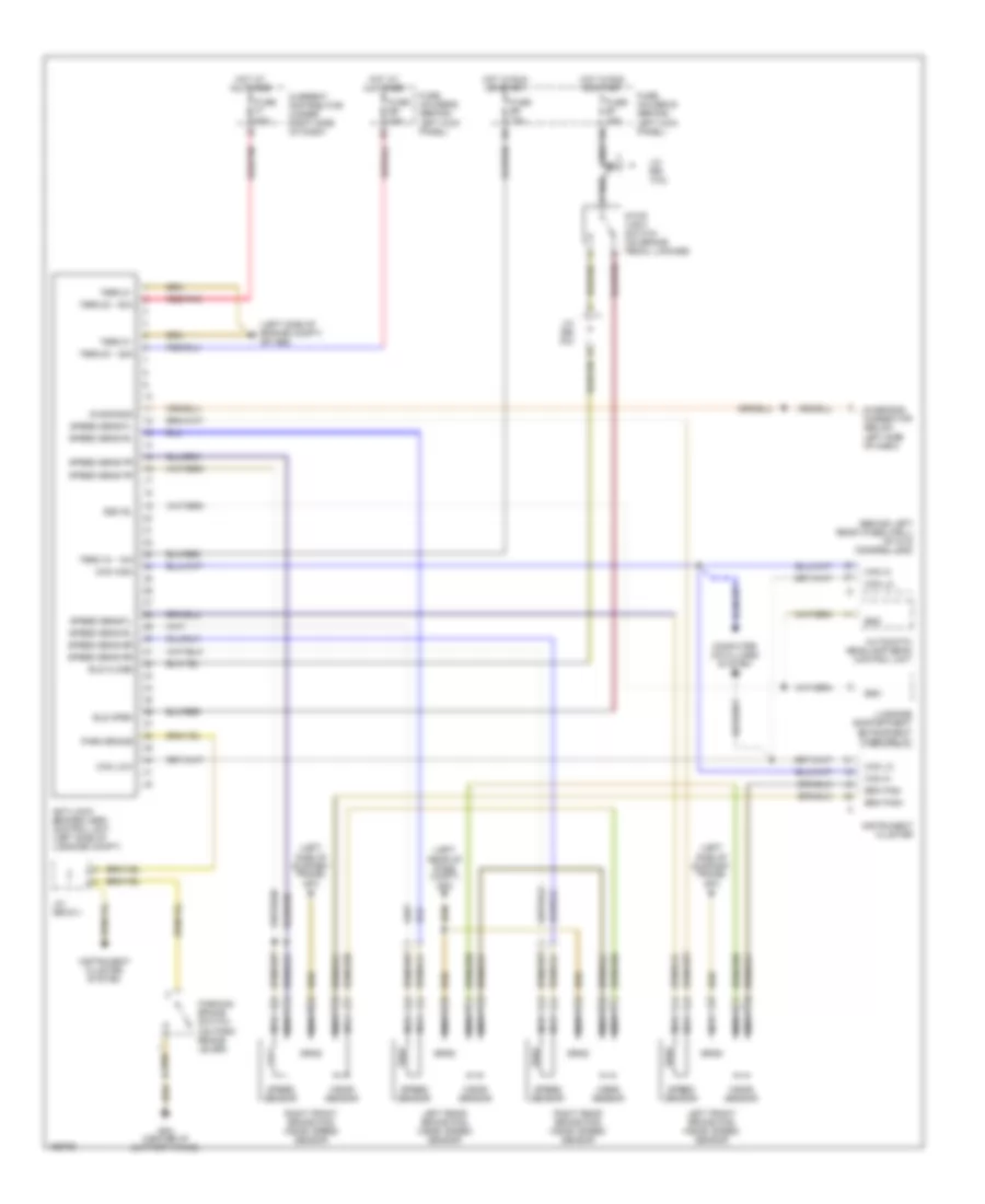
ANTI-LOCK BRAKES Anti-lock Brakes Wiring Diagram, with Stability Assist, Early Production for Porsche 911 Turbo 2005 List of elements for Anti-lock Brakes Wiring Diagram, with Stability Assist, Early Production for Porsche 911 Turbo 2005: 77 (front of brake booster) pre-charging pump (left rear of passenger compt) (left side of support frame) gp3 (on steering column) steering angle sensor (under right side of seat) ay sensor Automatic headlamp beam control unit Bls close Bls open Brake fluid level switch Brake fluid lvl Brk pad+ Brk pad- Can hi Can high Can lo Can low Current distributor (under right side of dash) Dgm Dgs Dgu Diagnosis Diagnosis connector (below left side of dash) Drsr Drss Drst Eso Eso rl Ferrite core Fuse b7 10a Fuse b9 15a Fuse e10 15a Fuse e9 25a Fuse f1 50a Fuse holder b (behind left kick panel, on fuses support) Fuse holder e (behind left kick panel, on fuses support) Gp psm (left side of lugg compt) Gp3 (left side of support frame) Gp4 (center of support frame) Gp8 Ground Hot at all times Hot in run or start Instrument cluster Instrument cluster system Interior lights system J/c (bs 14/2) J/c (bs 6/1) J/c (bs 6/2) Left front brake pad wear/ speed sensor Left rear brake pad wear/ speed sensor Luggage compartment entrapment timer relay Mfi & di control unit (behind left rear seatwell) Nca Park brake Parking brake switch (on park brake lever) Porsche stability management (psm) control unit (left side of luggage compt) Prechg pump Pressure sensor (integral to citation pump) Psm off Psm on Psm pala Psm switch Red/pnk Right front brake pad wear/ speed sensor Right rear brake pad wear/ speed sensor Speed sens fl Speed sens fr Speed sens rl Speed sens rr Speed sensor Stop light switch Term 15 - 15a Term 30 - 25a Term 30 - 50a Term 31 U+ sensors Wear sensor Anti-lock Brakes Wiring Diagram, without Stability Assist, Early Production for Porsche 911 Turbo 2005 List of elements for Anti-lock Brakes Wiring Diagram, without Stability Assist, Early Production for Porsche 911 Turbo 2005: 54 (behind left rear wheelwell) mfi & di control unit (left rear of pass compt) gp8 (left side of engine compt) gp abs (left side of support frame) gp3 Anti-lock brakes (abs) control unit (left side of luggage compt) Automatic headlamp beam control unit Bls close Bls open Brk pad+ Brk pad- Can hi Can high Can lo Can low Computer data lines system Current distributor (under right side of dash) Diagnosis Diagnosis connector (below left side of dash) Eso Eso rl Fuse b7 15a Fuse b9 15a Fuse e9 25a Fuse f1 50a Fuse holder b (behind left kick panel) Fuse holder e (behind left kick panel) Gp4 (center of support frame) Hot at all times Hot in run or start Instrument cluster Instrument cluster system J/c (bs 14/2) J/c (bs 6/1) J/c (bs 6/2) Left front brake pad wear/ speed sensor Left rear brake pad wear/ speed sensor Luggage compartment entrapment timer relay Nca Park brake Parking brake switch (on park brake lever) Red/pnk Right front brake pad wear/ speed sensor Right rear brake pad wear/ speed sensor Speed sens fl Speed sens fr Speed sens rl Speed sens rr Speed sensor Stop light switch (on brake pedal linkage) Term 15 - 15a Term 30 - 25a Term 30 - 50a Term 31 Wear sensor
ANTI-THEFT
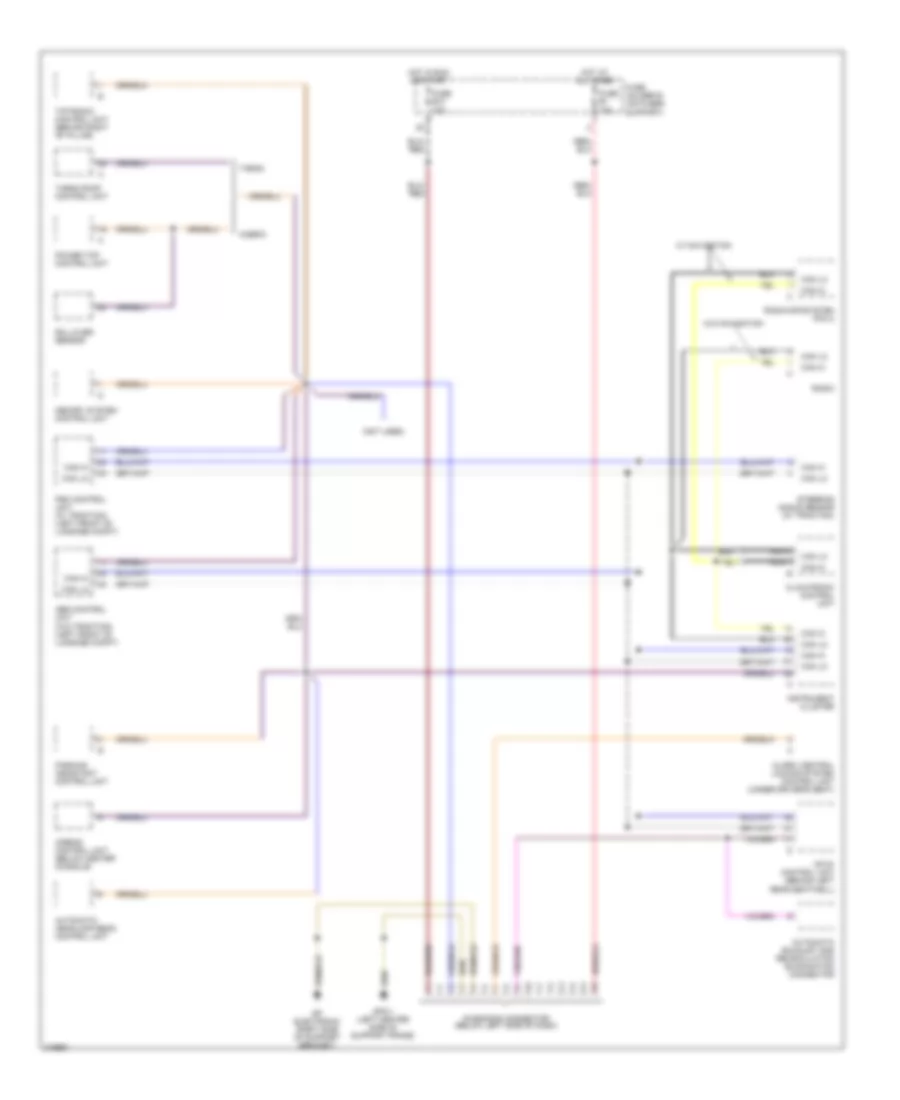
COMPUTER DATA LINES Computer Data Lines Wiring Diagram, Early Production for Porsche 911 Turbo 2005 List of elements for Computer Data Lines Wiring Diagram, Early Production for Porsche 911 Turbo 2005: 34 (not used) Abs control unit (w/o traction) (left front of luggage compt) Airbag control unit (below center console) Alarm/ central locking system control unit (under driver's seat) Automatic exhaust gas recirculation examination connector Automatic headlamp beam control unit Cabrio Can hi Can lo Climatronic control unit Diagnosis connector (below left side of dash) Fuse b1 15a Fuse b10 15a Fuse holder b (on fuses support) Gp electronic (right side of support bracket) Gp3/1 (left center side of support frame) Hot at all times Hot in run or start Instrument cluster Memory system control unit Mfi-di control unit (behind left rear seatwell) Nca Parking assistant control unit Power top control unit Psm control unit (w/ traction) (left front of luggage compt) Radio Radio/infosystem pcm 2 Rollover sensor Steering angle sensor (w/ traction) Targa Targa roof control unit Tiptronic control unit (behind right "b" pillar) W/ navigation W/o navigation
COOLING FAN Cooling Fan Wiring Diagram, Early Production for Porsche 911 Turbo 2005 List of elements for Cooling Fan Wiring Diagram, Early Production for Porsche 911 Turbo 2005: 30 0.55 ohms A/c relay control A/c system Can high Can low Computer data lines system Cooling blower stage 1 Cooling blower stage 2 Engine compartment blower motor Engine compartment blower relay Engine controls system Engine copart blower Fuse b4 15a Fuse c10 40a Fuse c8 40a Fuse holder b (on fuses support) Fuse holder c (on fuses support) Gp1 (right side Gp2 (left side Gp9 (right rear of passenger compartment) Hot at all times Left radiator fan motor Left radiator fan relay (step 1) (on relay support 1) Left radiator fan relay (step 2) (on relay support 1) Mfi-di control unit (behind left rear seatwell) Of luggage compartment) Right radiator fan motor Right radiator fan relay (setp 2) (on relay support 1) Right radiator fan relay (step 1) (on relay support 1) Term 87 output
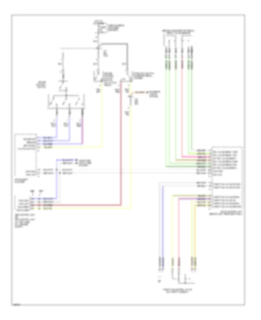
CRUISE CONTROL Cruise Control Wiring Diagram, Early Production for Porsche 911 Turbo 2005 List of elements for Cruise Control Wiring Diagram, Early Production for Porsche 911 Turbo 2005: 37 (behind accelerator pedal) pedal value sensor +5v pdl value sens 1 +5v pdl value sens 2 Abs Abs control unit or psm control unit (at left side of luggage compt) Bls close Bls open Can high Can low Clutch switch Computer data lines system Cruise control clutch switch (at clutch pedal) Cruise control switch Cruise off Exterior lights system Fuse b7 15a Fuse holder b (on fuses support) Hot at all times Instrument cluster J/c (bs 14/2) J/c (bs 6/2) Mfi-di control unit (behind left rear seatwell) Nca Pdl value sens 1 gnd Pdl value sens 1 sig Pdl value sens 2 gnd Pdl value sens 2 sig Psm Resume Set/accel Stoplight switch (on brake pedal, linkage) Throttle control valve (on throttle body) Throttle valve +5v Throttle valve ground Throttle valve motor+ Throttle valve motor- Throttle valve signal
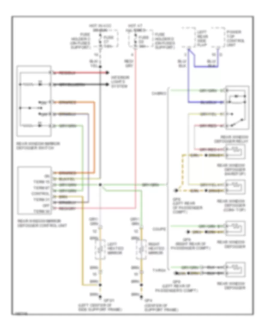
DEFOGGERS Defoggers Wiring Diagram, Early Production for Porsche 911 Turbo 2005 List of elements for Defoggers Wiring Diagram, Early Production for Porsche 911 Turbo 2005: 35 (center of support frame) (left center of side support frame) (left rear of passenger's compt) (right rear of passenger compt) Cabrio Control Coupe Fuse c7 7.5a Fuse d2 30a Fuse holder c (on fuses support) Fuse holder d (on fuses support) Gp3/1 Gp4 Gp8 Gp8 (left rear of passenger compt) Gp9 Hot at all times Hot in acc or run Interior lights system Left heated mirror Left rear side flap Off Power top control unit Rear window defogger Rear window defogger (conv top) Rear window defogger (hardtop) Rear window defogger relay Rear window/mirror defogger control unit Rear window/mirror defogger switch Right heated mirror Targa Term 15 Term 30 Term 31 Term 87
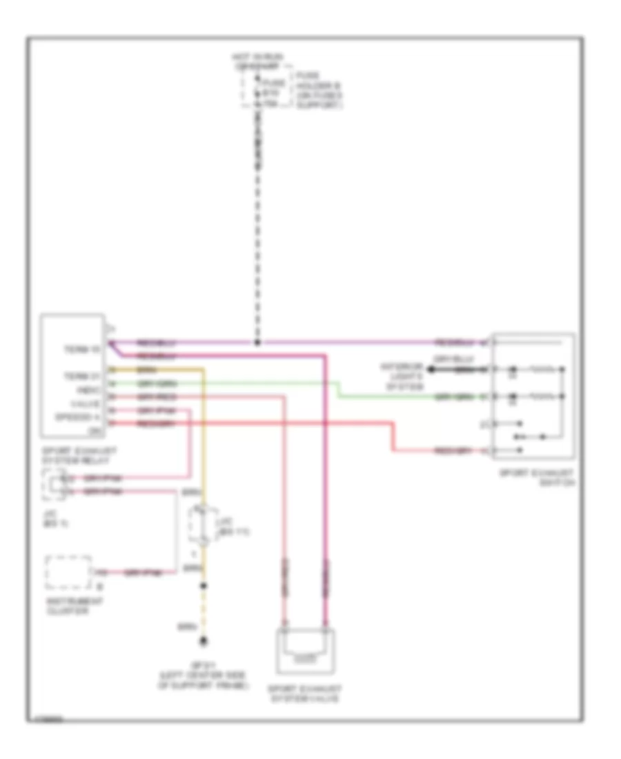
ELECTRONIC MUFFLER Electronic Muffler Wiring Diagram, Early Production for Porsche 911 Turbo 2005 List of elements for Electronic Muffler Wiring Diagram, Early Production for Porsche 911 Turbo 2005: 16 Fuse b10 15a Fuse holder b (on fuses support) Gp3/1 (left center side of support frame) Hot in run or start Indic Instrument cluster Interior lights system J/c (bs 1) J/c (bs 11) Speedo a Sport exhaust switch Sport exhaust system relay Sport exhaust system valve Term 15 Term 31 Valve
ENGINE PERFORMANCE
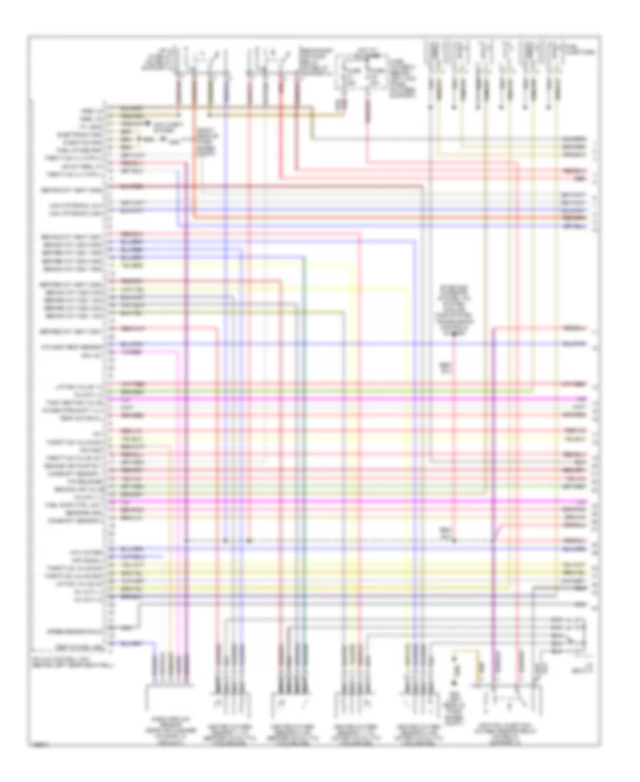
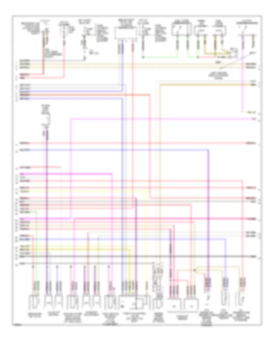
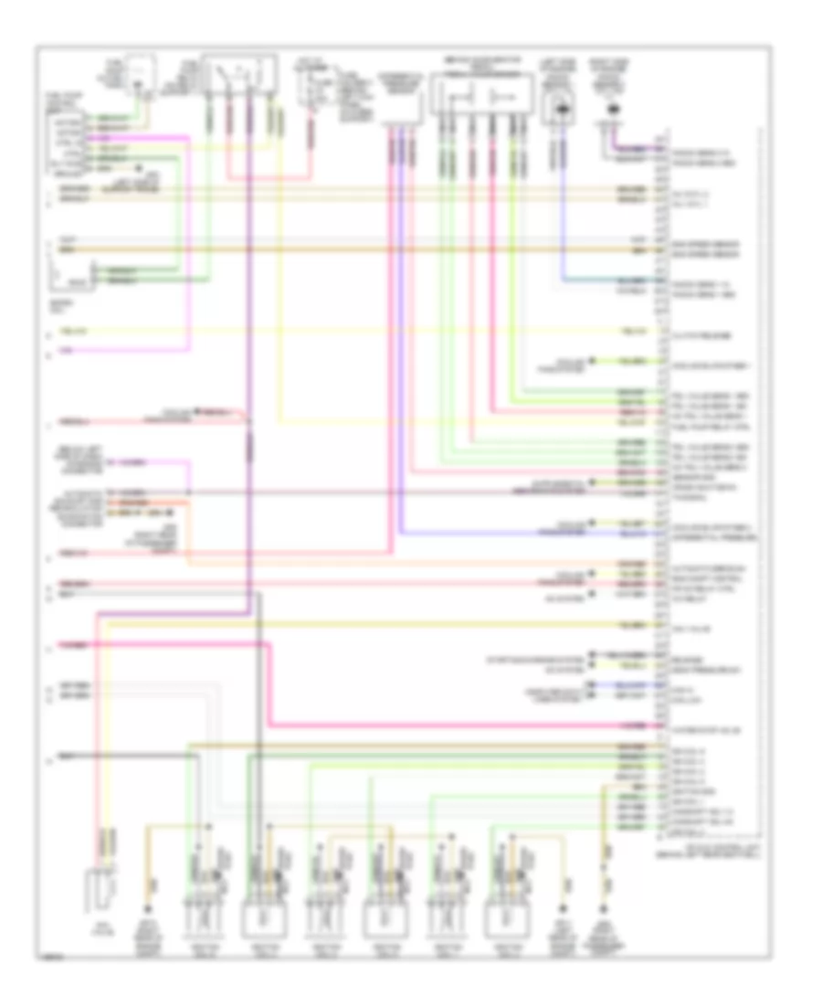
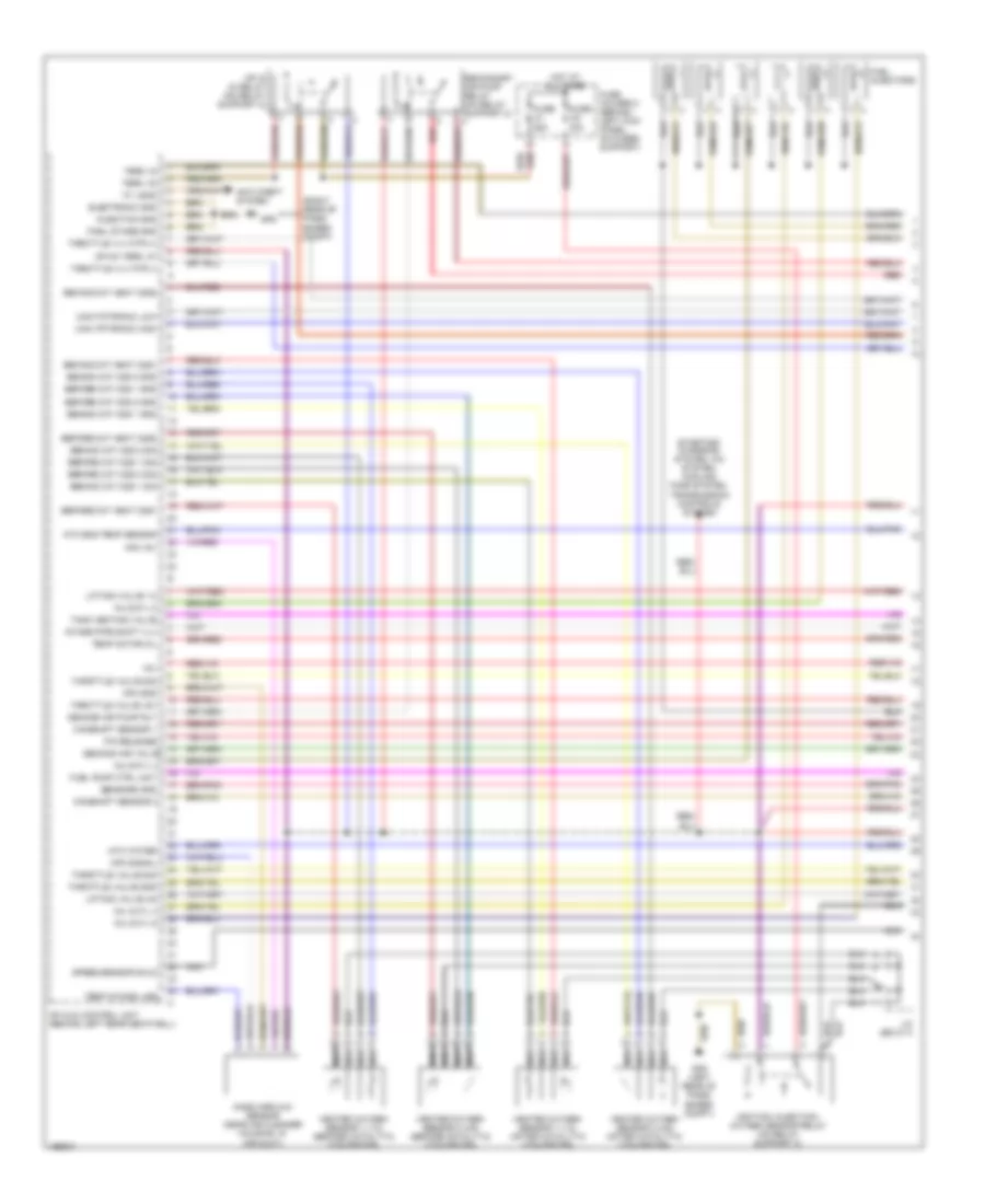
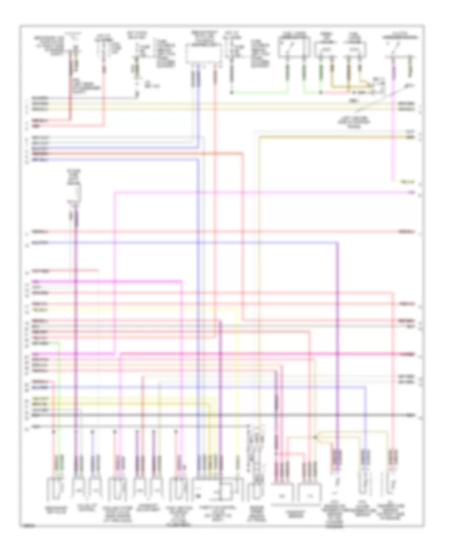
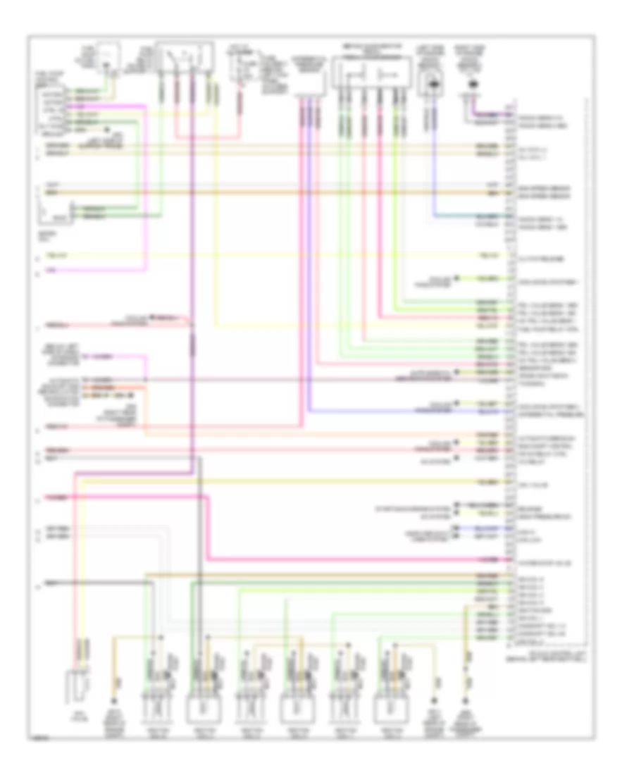
3.6L 3.6L, Engine Performance Wiring Diagram, Early Production (1 of 3) for Porsche 911 Turbo 2005 List of elements for 3.6L, Engine Performance Wiring Diagram, Early Production (1 of 3) for Porsche 911 Turbo 2005: 72 "w" lead (right rear of pass- enger compt) +5v Anti-theft system Before cat heat o2s1 Before cat heat o2s2 Before cat o2s 1 gnd Before cat o2s 1 sig Before cat o2s 2 gnd Before cat o2s 2 sig Behind cat heat o2s1 Behind cat heat o2s2 Behind cat o2s 1 gnd Behind cat o2s 1 sig Behind cat o2s 2 gnd Behind cat o2s 2 sig Camshaft sensor 1 Camshaft sensor 2 Can tiptronic high Can tiptronic low Electronic gnd Final stage gnd Fuel injectors Fuel pump ctrl unit Fuse c1 25a Fuse c2 30a Fuse holder c (behind left kick panel, on fuses support) Gp8 (left rear of pass- enger compt) Gp9 Heated oxygen sensor 1 (1-3) (after catalytic converter) Heated oxygen sensor 1 (1-3) (before catalytic converter) Heated oxygen sensor 2 (4-6) (after catalytic converter) Heated oxygen sensor 2 (4-6) (before catalytic converter) Hfm +5v Hfm gnd Hfm signal Hot at all times Ignition/ injection/ oxygen sensor relay (on relay support 2) Inj 2/cyl 6 Inj 4/cyl 4 Inj 5/cyl 3 Inj 6/cyl 5 Injection gnd Intake pipe shift vlv J/c (bs 21/1) Lifting valve 1-3 Lifting valve 4-6 Mass airflow sensor (near air cleaner housing, in air duct) Mfi & di control unit (behind left rear seatwell) Mfi & di relay (on relay support 2) Mfi+di term. 87 Nca Ntc eng temp sensor Ntc water P/n release Red Second air pump rly Second air valve Secondary air pump relay (on relay support 2) Sensors gnd Speed sensor shld Starting/ charging system, a/c system, cooling fans system, transmission controls system Tank venting valve Temp intake line Temp motor oil Term 15 Term. 30 Throttle valve +5v Throttle valve gnd Throttle valve sig Throttle vlv mtr (+) Throttle vlv mtr (-) 3.6L, Engine Performance Wiring Diagram, Early Production (2 of 3) for Porsche 911 Turbo 2005 List of elements for 3.6L, Engine Performance Wiring Diagram, Early Production (2 of 3) for Porsche 911 Turbo 2005: 34 (behind right "b" pillar) tiptronic control unit (bs 11) j/c (left center side of support frame) 1-3 4-6 Camshaft adjustment Camshaft sensor Clutch interlock switch Cooling water stop valve (near engine lift provision) Engine speed sensor (in trans) Fresh air valve Fuel vapor reed switch Fuel vapor valve Fuse b8 15a Fuse e6 15a Fuse holder b (behind left kick panel, on fuses support) Fuse holder e (behind left kick panel, on fuses support) Gp3/1 Gp8 (left rear of passenger compt) Hot at all times Hot in run or start Intake pipe shift valve J/c (bs 13/2) Maxi fuse 40a Nca Ntc engine air temperature sensor (at air cleaner housing) Ntc water temperature sensor Oil temperature sensor (on right side of engine) Red Secondary air pump motor (at right side of engine compt) Secondary air valve Tank venting solenoid valve (at fuel filler neck) Throttle control valve (on throttle body) Valve lift control 3.6L, Engine Performance Wiring Diagram, Early Production (3 of 3) for Porsche 911 Turbo 2005 List of elements for 3.6L, Engine Performance Wiring Diagram, Early Production (3 of 3) for Porsche 911 Turbo 2005: 78 (behind accelerator pedal) pedal value sensor (below left side of dash) diagnosis connector (left side of engine) knock sensor 1 (cyl 1-3) (right side of engine) knock sensor 2 (cyl 4-6) +5v pdl value sens 1 +5v pdl value sens 2 A/c relay A/c system Aav valve Automatic egr exam Automatic exhaust gas Camshaft adj 1-3 Camshaft adj 4-6 Can hi Can low Clutch release Computer data lines system Cooling blwr stage 1 Cooling blwr stage 2 Cooling fans system Crash shut-down Ctrl Ctrl in Differential pressure Differential pressure sensor Ekpsm coil Eng compt control Eng speed sensor Fuel pump (in fuel tank) Fuel pump control unit Fuel pump relay (on relay support 1) Fuel pump relay ctrl Fuse c4 30a Fuse holder c (behind left kick panel, on fuses support) Gp10 (right rear of engine compt) Gp11 (left rear of engine compt) Gp3 (left side of support frame) Gp9 (right rear of passenger compt) Ground Hot at all times Ign coil 1 Ign coil 2 Ign coil 3 Ign coil 4 Ign coil 5 Ign coil 6 Ignition coil 1 Ignition coil 2 Ignition coil 3 Ignition coil 4 Ignition coil 5 Ignition coil 6 Ignition gnd Inj 1/cyl 1 Inj 3/cyl 2 Knock sens 1 gnd Knock sens 1 in Knock sens 2 gnd Knock sens 2 in Mean pressure sw Mfi & di control unit (behind left rear seatwell) Mfi+di relay ctrl Motor+ Motor- Nca Pdl value sens 1 gnd Pdl value sens 1 sig Pdl value sens 2 gnd Pdl value sens 2 sig Plug spark Recirculation examination connector Release Rly pwr Sensor gnd Spark plug Starting/charging system Tn-signal Water stop valve
3.8L 3.8L, Engine Performance Wiring Diagram, Early Production (1 of 3) for Porsche 911 Turbo 2005 List of elements for 3.8L, Engine Performance Wiring Diagram, Early Production (1 of 3) for Porsche 911 Turbo 2005: 72 "w" lead (right rear of pass- enger compt) +5v Anti-theft system Before cat heat o2s1 Before cat heat o2s2 Before cat o2s 1 gnd Before cat o2s 1 sig Before cat o2s 2 gnd Before cat o2s 2 sig Behind cat heat o2s1 Behind cat heat o2s2 Behind cat o2s 1 gnd Behind cat o2s 1 sig Behind cat o2s 2 gnd Behind cat o2s 2 sig Camshaft sensor 1 Camshaft sensor 2 Can tiptronic high Can tiptronic low Electronic gnd Final stage gnd Fuel injectors Fuel pump ctrl unit Fuse c1 25a Fuse c2 30a Fuse holder c (behind left kick panel, on fuses support) Gp8 (left rear of pass- enger compt) Gp9 Heated oxygen sensor 1 (1-3) (after catalytic converter) Heated oxygen sensor 1 (1-3) (before catalytic converter) Heated oxygen sensor 2 (4-6) (after catalytic converter) Heated oxygen sensor 2 (4-6) (before catalytic converter) Hfm +5v Hfm gnd Hfm signal Hot at all times Ignition/ injection/ oxygen sensor relay (on relay support 2) Inj 2/cyl 6 Inj 4/cyl 4 Inj 5/cyl 3 Inj 6/cyl 5 Injection gnd Intake pipe shift vlv J/c (bs 21/1) Lifting valve 1-3 Lifting valve 4-6 Mass airflow sensor (near air cleaner housing, in air duct) Mfi & di control unit (behind left rear seatwell) Mfi & di relay (on relay support 2) Mfi+di term. 87 Nca Ntc eng temp sensor Ntc water P/n release Red Second air pump rly Second air valve Secondary air pump relay (on relay support 2) Sensors gnd Speed sensor shld Starting/ charging system, a/c system, cooling fans system, transmission controls system Tank venting valve Temp intake line Temp motor oil Term 15 Term. 30 Throttle valve +5v Throttle valve gnd Throttle valve sig Throttle vlv mtr (+) Throttle vlv mtr (-) 3.8L, Engine Performance Wiring Diagram, Early Production (2 of 3) for Porsche 911 Turbo 2005 List of elements for 3.8L, Engine Performance Wiring Diagram, Early Production (2 of 3) for Porsche 911 Turbo 2005: 34 (behind right "b" pillar) tiptronic control unit (bs 11) j/c (left center side of support frame) 1-3 4-6 Camshaft adjustment Camshaft sensor Clutch interlock switch Cooling water stop valve (near engine lift provision) Engine speed sensor (in trans) Fresh air valve Fuel vapor reed switch Fuel vapor valve Fuse b8 15a Fuse e6 15a Fuse holder b (behind left kick panel, on fuses support) Fuse holder e (behind left kick panel, on fuses support) Gp3/1 Gp8 (left rear of passenger compt) Hot at all times Hot in run or start Intake pipe shift valve J/c (bs 13/2) Maxi fuse 40a Nca Ntc engine air temperature sensor (at air cleaner housing) Ntc water temperature sensor Oil temperature sensor (on right side of engine) Red Secondary air pump motor (at right side of engine compt) Secondary air valve Tank venting solenoid valve (at fuel filler neck) Throttle control valve (on throttle body) Valve lift control 3.8L, Engine Performance Wiring Diagram, Early Production (3 of 3) for Porsche 911 Turbo 2005 List of elements for 3.8L, Engine Performance Wiring Diagram, Early Production (3 of 3) for Porsche 911 Turbo 2005: 78 (behind accelerator pedal) pedal value sensor (below left side of dash) diagnosis connector (left side of engine) knock sensor 1 (cyl 1-3) (right side of engine) knock sensor 2 (cyl 4-6) +5v pdl value sens 1 +5v pdl value sens 2 A/c relay A/c system Aav valve Automatic egr exam Automatic exhaust gas Camshaft adj 1-3 Camshaft adj 4-6 Can hi Can low Clutch release Computer data lines system Cooling blwr stage 1 Cooling blwr stage 2 Cooling fans system Crash shut-down Ctrl Ctrl in Differential pressure Differential pressure sensor Ekpsm coil Eng compt control Eng speed sensor Fuel pump (in fuel tank) Fuel pump control unit Fuel pump relay (on relay support 1) Fuel pump relay ctrl Fuse c4 30a Fuse holder c (behind left kick panel, on fuses support) Gp10 (right rear of engine compt) Gp11 (left rear of engine compt) Gp3 (left side of support frame) Gp9 (right rear of passenger compt) Ground Hot at all times Ign coil 1 Ign coil 2 Ign coil 3 Ign coil 4 Ign coil 5 Ign coil 6 Ignition coil 1 Ignition coil 2 Ignition coil 3 Ignition coil 4 Ignition coil 5 Ignition coil 6 Ignition gnd Inj 1/cyl 1 Inj 3/cyl 2 Knock sens 1 gnd Knock sens 1 in Knock sens 2 gnd Knock sens 2 in Mean pressure sw Mfi & di control unit (behind left rear seatwell) Mfi+di relay ctrl Motor+ Motor- Nca Pdl value sens 1 gnd Pdl value sens 1 sig Pdl value sens 2 gnd Pdl value sens 2 sig Plug spark Recirculation examination connector Release Rly pwr Sensor gnd Spark plug Starting/charging system Tn-signal Water stop valve
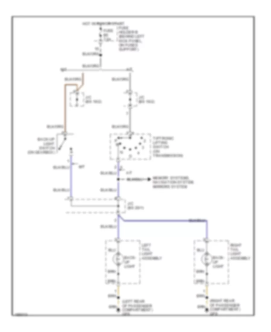
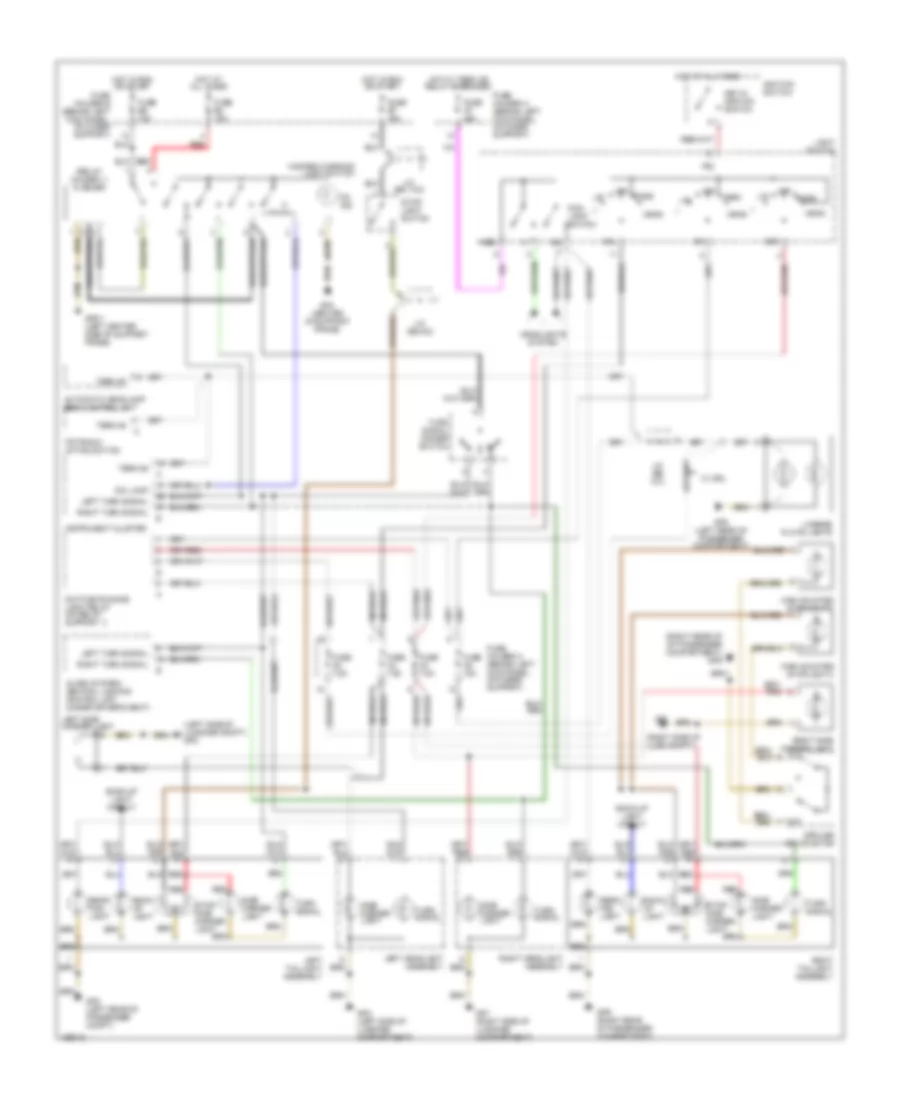
EXTERIOR LIGHTS Back-up Lamps Wiring Diagram, Early Production for Porsche 911 Turbo 2005 List of elements for Back-up Lamps Wiring Diagram, Early Production for Porsche 911 Turbo 2005: 16 (left rear of passenger compartment) gp8 (right rear of passenger compartment) gp9 A/t Back- up light Back-up light switch (on gearbox) Fuse b5 7.5a Fuse holder b (behind left kick panel, on fuses support) Hot in run or start J/c (bs 16/2) J/c (bs 20/1) Left tail light assembly M/t Memory systems, navigation system, mirrors system P r Right tail light assembly Tiptronic lifting switch (on transmission) Exterior Lamps Wiring Diagram, Early Production for Porsche 911 Turbo 2005 List of elements for Exterior Lamps Wiring Diagram, Early Production for Porsche 911 Turbo 2005: 74 (left side of luggage compt) gp2 (relay holder 1) flasher (right rear of of passenger compartment) gp9 (right side of lugg compt) 58l 58r Alarm system/ central locking control unit (under driver's seat) Automatic headlamp beam control unit Back- up light Back-up light circuit Daytime running light relay (on relay support 1) Dim lamp Fog- light switch Fuse a3 7.5a Fuse a4 7.5a Fuse a5 15a Fuse a7 25a Fuse a8 7.5a Fuse b2 15a Fuse b6 15a Fuse b7 15a Fuse holder a (behind left kick panel, on fuses support) Fuse holder b (behind left kick panel, on fuses support) Gp1 Gp1 (right side of luggage compartment) Gp2 (left side of luggage compartment) Gp3/1 (left center side of support frame) Gp4 (center of support frame) Gp8 (left rear of passenger compartment) Gp8 (left rear of passenger compt) Gp9 (right rear of passenger compartment) Hazard/ warning light switch Head Headlights system High mounted stoplight 1 High mounted stoplight 2 Hot at all times Hot in run or start Hot w/ term xe relay energized Ignition switch Instrument cluster J/c (bs 10/1) J/c (bs 14/2) J/c (bs 6/2) Key-in ignition switch L head L/r Left headlight assembly Left side marker light Left taillight assembly Left turn signal License plate lights Light switch Nse Off On ind P30 Park Rear fog light Rear fog- light Red Right headlight assembly Right side marker light Right taillight assembly Right turn signal Side marker light Spoiler drive motor Stop- light switch Stop/ side marker light Term 58 Tiptronic lifting switch Turn signal Turn signal dimmer switch W/ drl
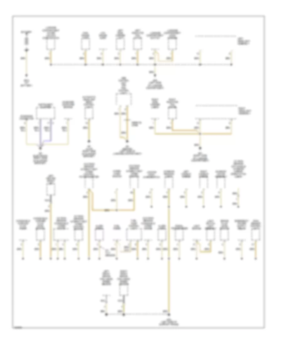
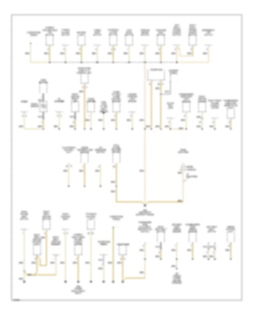
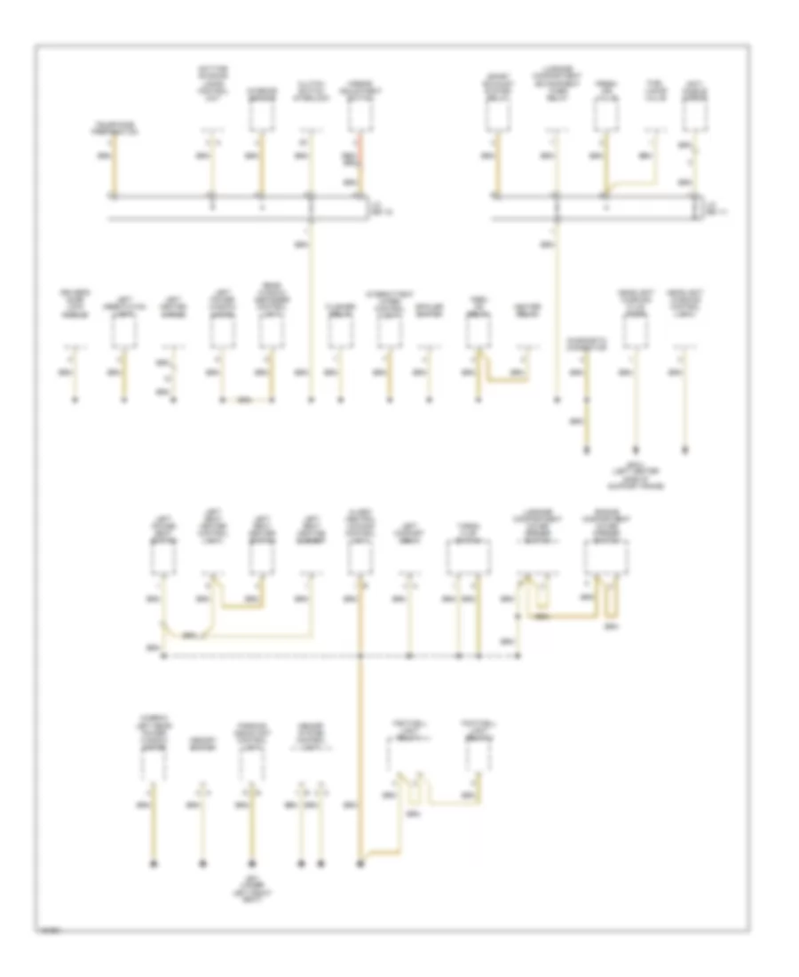
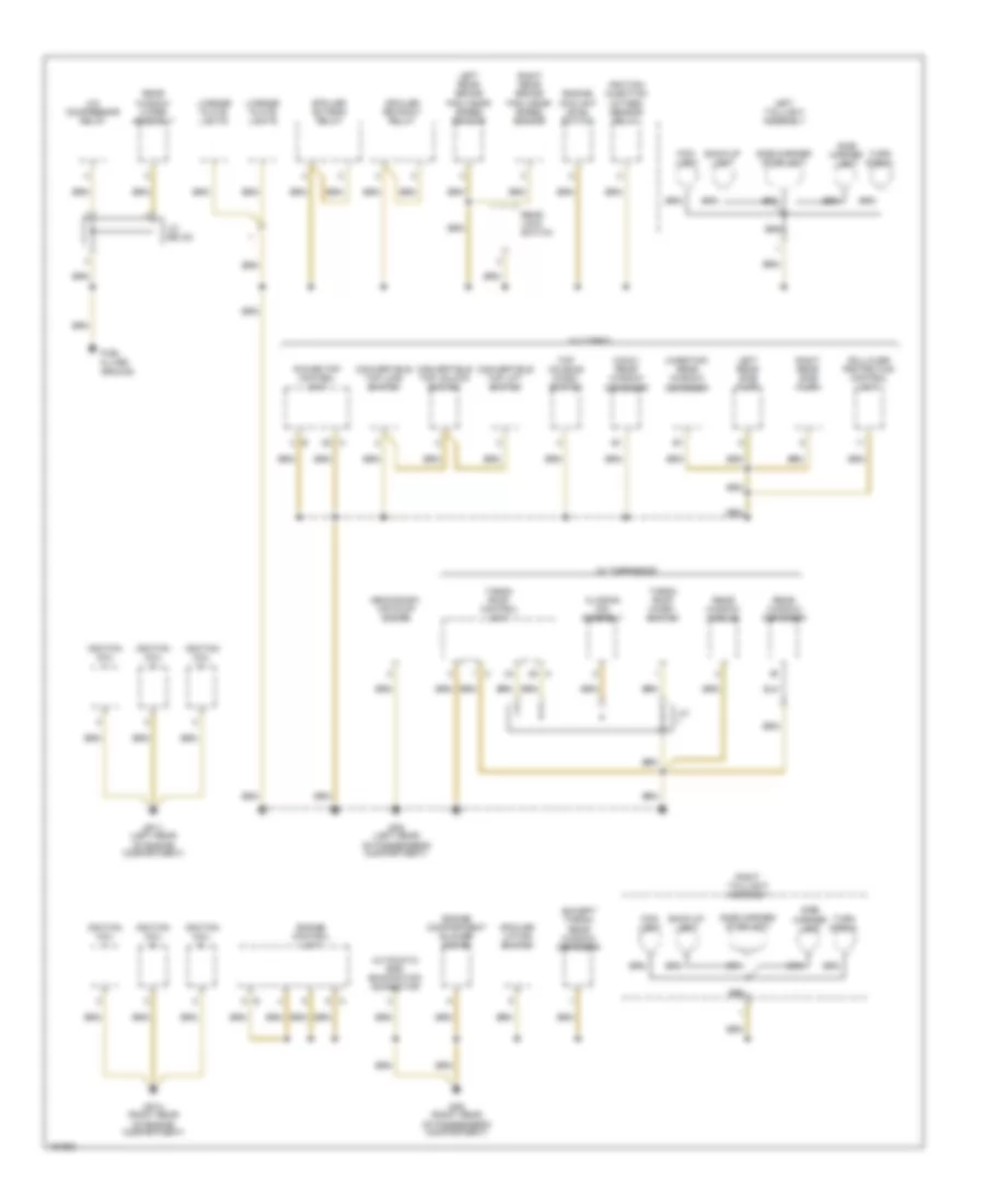
GROUND DISTRIBUTION Ground Distribution Wiring Diagram, Early Production (1 of 4) for Porsche 911 Turbo 2005 List of elements for Ground Distribution Wiring Diagram, Early Production (1 of 4) for Porsche 911 Turbo 2005: 53 (w/ rain sensor) anti-dazzle interior mirror orientation light (w/ rain sensor) intermittent wiper control switch (w/ rain sensor) windshield wiper motor (w/ tilt sensor) (w/o rain sensor) intermittent wiper control (w/o rain sensor) intermittent wiper control potentiometer (w/o rain sensor) windshield wiper motor Abs control unit (or) psm control unit Alarm horn Alarm siren Automatic headlamp beam control unit Battery Brake fluid level switch Diagnosis connector Ferrite core Fuel pump Fuel pump control unit Gp abs/psm (left side of luggage compartment) Gp alwr (right side of support bracket) Gp electronic (right side of support bracket) Gp1 (right side of luggage compartment) Gp13 (at battery) Gp2 (left side of luggage compartment) Gp3 (left side of support frame) High range horn Instrument cluster Interior reading light Left front brake pad wear/ speed sensor Left headlight assembly Left heated spray jet Left makeup mirror Left radiator fan motor Left side marker light Light switch Light switch light assembly Locking hook micro-switch Low range horn Luggage compartment cover unlock micro-switch Luggage compartment hood opener Luggage compartment switch Nca On-board computer switch Rain sensor control unit Right front brake pad wear/ speed sensor Right headlight assembly Right makeup mirror Right radiator fan motor Right side marker light Signal transformer Sunroof motor assembly Windshield washer fluid level switch Windshield washing fluid pump Wiper/ wash switch Ground Distribution Wiring Diagram, Early Production (2 of 4) for Porsche 911 Turbo 2005 List of elements for Ground Distribution Wiring Diagram, Early Production (2 of 4) for Porsche 911 Turbo 2005: 55 (bose) (cabrio) convertible top switch (cabrio) right rear power window motor (if equipped) (targa) blinds switch A (harman) A/c pressure switch Airbag control unit Ashtray light Bose amplifier Cd changer Cigar lighter Climatronic control unit Driver's side airbag sensor Emergency off switch Final stage (blower driver) Fuel tank filler neck ground Glove box lamp Gp airbag (under center console) Gp4 (center of support frame) Gp6 (under right front seat) Handset shield Hazard/ warning light switch Horn button Infosystem display & control unit Inside temperature sensor Inter- mittent wiper control switch Kick down switch Left front power window switch Left seat belt switch Microphone shield Nca Package tray switch Parking brake switch Passenger side child seat recognition switch Passenger's side airbag sensor Passenger's side door lock module Passenger's side door orientation light Radio Right comfort seat Right front power window motor Right front power window switch Right heated mirror Right heated spray jet Right power seat switch Right seat belt switch Right seat heater control unit Right seat heater switch Right seat heating element Spiral spring Targa roof switch Telephone Telephone e-box Tiptronic control unit Tiptronic lifting switch Ground Distribution Wiring Diagram, Early Production (3 of 4) for Porsche 911 Turbo 2005 List of elements for Ground Distribution Wiring Diagram, Early Production (3 of 4) for Porsche 911 Turbo 2005: 42 (cabrio) left rear power window motor Alarm/ central locking control unit Anti- dazzle mirror Clutch switch interlock Daytime running lamps control unit Diagnostic connector Driver's door lock module Engine compartment cover opener switch Flasher relay Footwell light relay 1 Footwell light relay 2 Fresh air valve Fuel vapor valve Gp3/1 (left center side of support frame) Gp7 (under left front seat) Headlight washing control unit Headlight washing fluid pump Heater relay Interior sensor Intermittent wiper control unit J/c (bs 11) J/c (bs 12) Left comfort seat Left heated mirror Left orientation light Left power seat switch Left power window motor Left seat heater control unit Left seat heater switch Left seat heating element Luggage compartment cover opener switch Luggage compartment entrapment timer relay Memory switch Memory system control unit Mirror adjustment switch Parking assistant control unit Rear window defogger control unit Spoiler switch Sport exhaust system relay Targa flap switch Telephone preparation Term xe relay Ground Distribution Wiring Diagram, Early Production (4 of 4) for Porsche 911 Turbo 2005 List of elements for Ground Distribution Wiring Diagram, Early Production (4 of 4) for Porsche 911 Turbo 2005: 48 (conv) rear window defogger (except targa) rear window defogger (hardtop) rear window defogger A/c compressor relay Automatic egr examination connector Back-up light Closing aid assembly Convertible top lift switch Convertible top lock switch Convertible top unlock switch Engine compartment blower motor Engine control unit Engine coolant level switch Fog- light Fuel filter ground Gp10 (right rear of engine compartment) Gp11 (left rear of engine compartment) Gp8 (left rear of passenger's compartment) Gp9 (right rear of passenger's compartment) Ignition coil Ignition/ injection oxygen sensor relay J/c J/c (bs 22) Left rear brake pad wear/ speed sensor Left rear side flap Left taillight assembly License plate lights Power top control unit Rear lock switch Rear window defogger Rear window module Rear window wiper assembly Right rear brake pad wear/ speed sensor Right rear side flap Right taillight assembly Rollover protection control unit Secondary air pump motor Side marker light Side marker/ stoplight Spoiler extend relay Spoiler lifting switch Spoiler retract relay Targa roof control unit Targa roof micro- switch Top housing micro- switch Turn signal W/ cabrio W/ targaroof
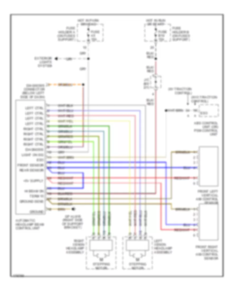
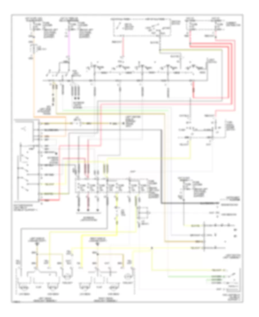
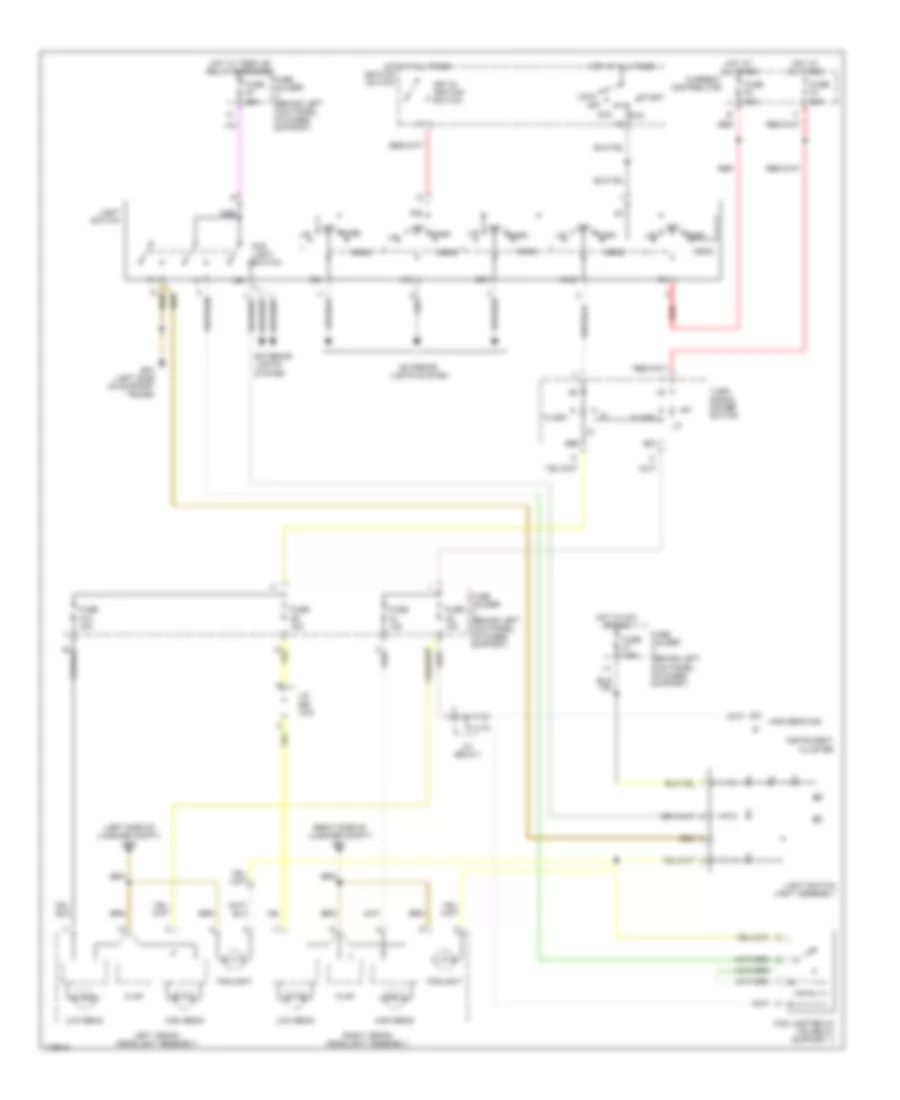
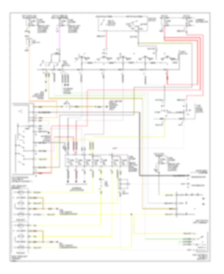
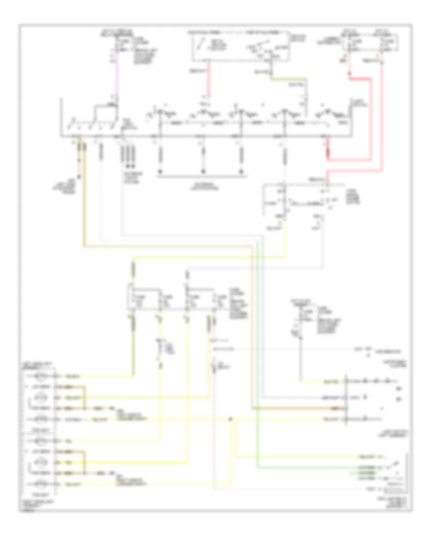
HEADLIGHTS Headlamp Beam Adjustment Wiring Diagram, Early Production for Porsche 911 Turbo 2005 List of elements for Headlamp Beam Adjustment Wiring Diagram, Early Production for Porsche 911 Turbo 2005: 30 (w/ traction control) (w/o traction control) Abs control unit (or) psm control unit Automatic headlamp beam control unit Diagnosis Diagnosis connector (below left side of dash) Eso Exterior lights system Front left vertical aim control sensor Front right vertical aim control sensor Front sensor Fuse a5 15a Fuse b10 15a Fuse holder a (on fuses support) Fuse holder b (on fuses support) Gp alwr (right side of support bracket) Ground Ground sens Hi beam on Hot in park or head Hot in run or start J/c (bs 2/1) Left ctrl Left xenon headlamp assembly Light on sig Rear sensor Right ctrl Right xenon headlamp assembly Stepping motor Term 15 Headlamps & Fog Lamps Wiring Diagram, with Xenon Lamps, with DRL, Early Production for Porsche 911 Turbo 2005 List of elements for Headlamps & Fog Lamps Wiring Diagram, with Xenon Lamps, with DRL, Early Production for Porsche 911 Turbo 2005: 64 (left center side of support frame) gp3/1 (left side of luggage compt) gp2 (right side of luggage compt) gp1 56a 56b 58l 58r Acc Current distributor Daytime running light relay (on relay support 1) Engine run sig Exterior lights system Flap Flash Fog light switch Fog lamp relay (on relay support 1) Foglight Fuse a1 15a Fuse a10 15a Fuse a2 15a Fuse a3 7.5a Fuse a4 7.5a Fuse a5 15a Fuse a7 25a Fuse a9 15a Fuse c7 7.5a Fuse e1 7.5a Fuse f2 80a Fuse f4 80a Fuse holder a (behind left kick panel, on fuses support) Fuse holder c (behind left kick panel, on fuses support) Fuse holder e (behind left kick panel, on fuses support) Gp3 (left side of support frame) Head High beam High beam ind Hot at all times Hot in acc or run Hot in off, acc, run or start Hot w/ term xe relay energized Ignition switch Instrument cluster J/c (bs 10/2) J/c (bs 12) J/c (bs 13/1) J/c (bs 5/1) Key-in ignition switch Kl56 L head L/r Left xenon headlight assembly Light switch Light switch light assembly Lock Low beam Nse Off P30 Park Red Right xenon headlight assembly Run Start Turn signal dimmer switch Headlamps & Fog Lamps Wiring Diagram, with Xenon Lamps, without DRL, Early Production for Porsche 911 Turbo 2005 List of elements for Headlamps & Fog Lamps Wiring Diagram, with Xenon Lamps, without DRL, Early Production for Porsche 911 Turbo 2005: 53 (left side of luggage compt) gp2 (right side of luggage compt) gp1 56a 56b 58l 58r Acc Current distributor Exterior lights system Flap Flash Fog light switch Fog lamp relay (on relay support 1) Foglight Fuse a1 15a Fuse a10 15a Fuse a2 15a Fuse a7 25a Fuse a9 15a Fuse c7 7.5a Fuse f2 80a Fuse f4 80a Fuse holder a (behind left kick panel, on fuses support) Fuse holder c (behind left kick panel, on fuses support) Gp3 (left side of support frame) Head High beam High beam ind Hot at all times Hot in acc or run Hot w/ term xe relay energized Ignition switch Instrument cluster J/c (bs 10/2) J/c (bs 5/1) Key-in ignition switch Kl56 L head L/r Left xenon headlight assembly Light switch Light switch light assembly Lock Low beam Nse Off P30 Park Red Right xenon headlight assembly Run Start Turn signal dimmer switch Headlamps & Fog Lamps Wiring Diagram, without Xenon Lamps, with DRL, Early Production for Porsche 911 Turbo 2005 List of elements for Headlamps & Fog Lamps Wiring Diagram, without Xenon Lamps, with DRL, Early Production for Porsche 911 Turbo 2005: 64 (left center side of support frame) gp3/1 56a 56b 58l 58r Acc Current distributor Daytime running light relay (on relay support 1) Engine run sig Exterior lights system Flash Fog light switch Fog lamp relay (on relay support 1) Foglight Fuse a1 15a Fuse a10 15a Fuse a2 15a Fuse a3 7.5a Fuse a4 7.5a Fuse a5 15a Fuse a7 25a Fuse a9 15a Fuse c7 7.5a Fuse e1 7.5a Fuse f2 80a Fuse f4 80a Fuse holder a (behind left kick panel, on fuses support) Fuse holder a (behind left kick panel, on fuses support) Fuse holder c (behind left kick panel, on fuses support) Fuse holder e (behind left kick panel, on fuses support) Gp1 (right side of luggage support) Gp2 (left side of luggage support) Gp3 (left side of support frame) Head High beam High beam ind Hot at all times Hot in acc or run Hot in off, acc, run or start Hot w/ term xe relay energized Ignition switch Instrument cluster J/c (bs 10/2) J/c (bs 12) J/c (bs 13/1) J/c (bs 5/1) Key-in ignition switch Kl56 L head L/r Left headlight assembly Light switch Light switch light assembly Lock Low beam Nse Off P30 Park Red Right headlight assembly Run Start Turn signal dimmer switch Headlamps & Fog Lamps Wiring Diagram, without Xenon Lamps, without DRL, Early Production for Porsche 911 Turbo 2005 List of elements for Headlamps & Fog Lamps Wiring Diagram, without Xenon Lamps, without DRL, Early Production for Porsche 911 Turbo 2005: 53 56a 56b 58l 58r Acc Current distributor Exterior lights system Flash Fog light switch Fog lamp relay (on relay support 1) Foglight Fuse a1 15a Fuse a10 15a Fuse a2 15a Fuse a7 25a Fuse a9 15a Fuse c7 7.5a Fuse f2 80a Fuse f4 80a Fuse holder a (behind kick left panel, on fuses support) Fuse holder a (behind left kick panel, on fuses support) Fuse holder c (behind left kick panel, on fuses support) Gp1 (right side of luggage compt) Gp2 (left side of luggage compt) Gp3 (left side of support frame) Head High beam High beam ind Hot at all times Hot in acc or run Hot w/ term xe relay energized Ignition switch Instrument cluster J/c (bs 10/2) J/c (bs 5/1) Key-in ignition switch Kl56 L head L/r Left headlight assembly Light switch Light switch light assembly Lock Low beam Nse Off P30 Park Red Right headlight assembly Run Start Turn signal dimmer switch
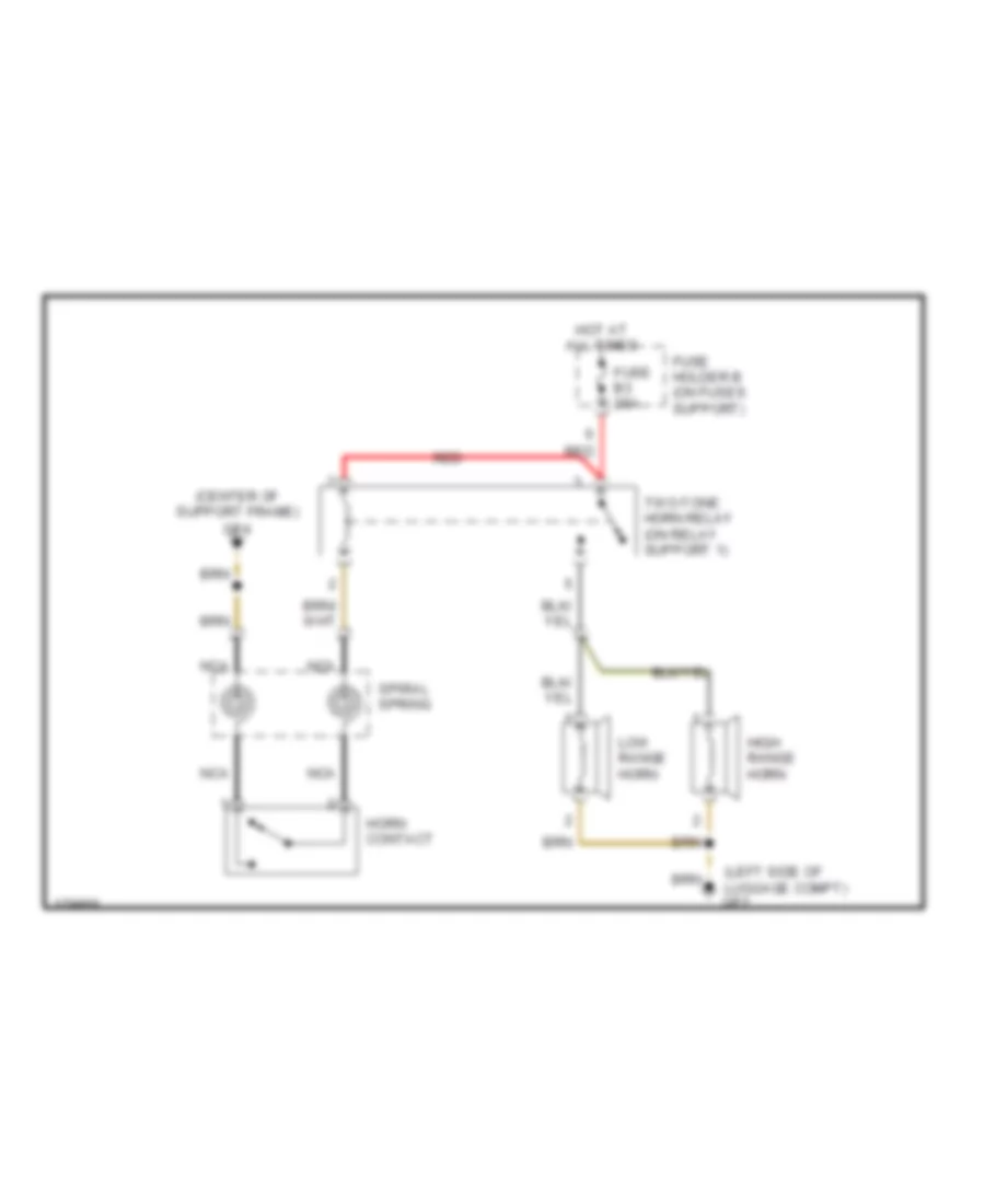
HORN Horn Wiring Diagram, Early Production for Porsche 911 Turbo 2005 List of elements for Horn Wiring Diagram, Early Production for Porsche 911 Turbo 2005: 12 (center of support frame) gp4 (left side of luggage compt) gp2 Fuse b3 25a Fuse holder b (on fuses support) High range horn Horn contact Hot at all times Low range horn Nca Red Spiral spring Two-tone horn relay (on relay support 1)
INSTRUMENT CLUSTER
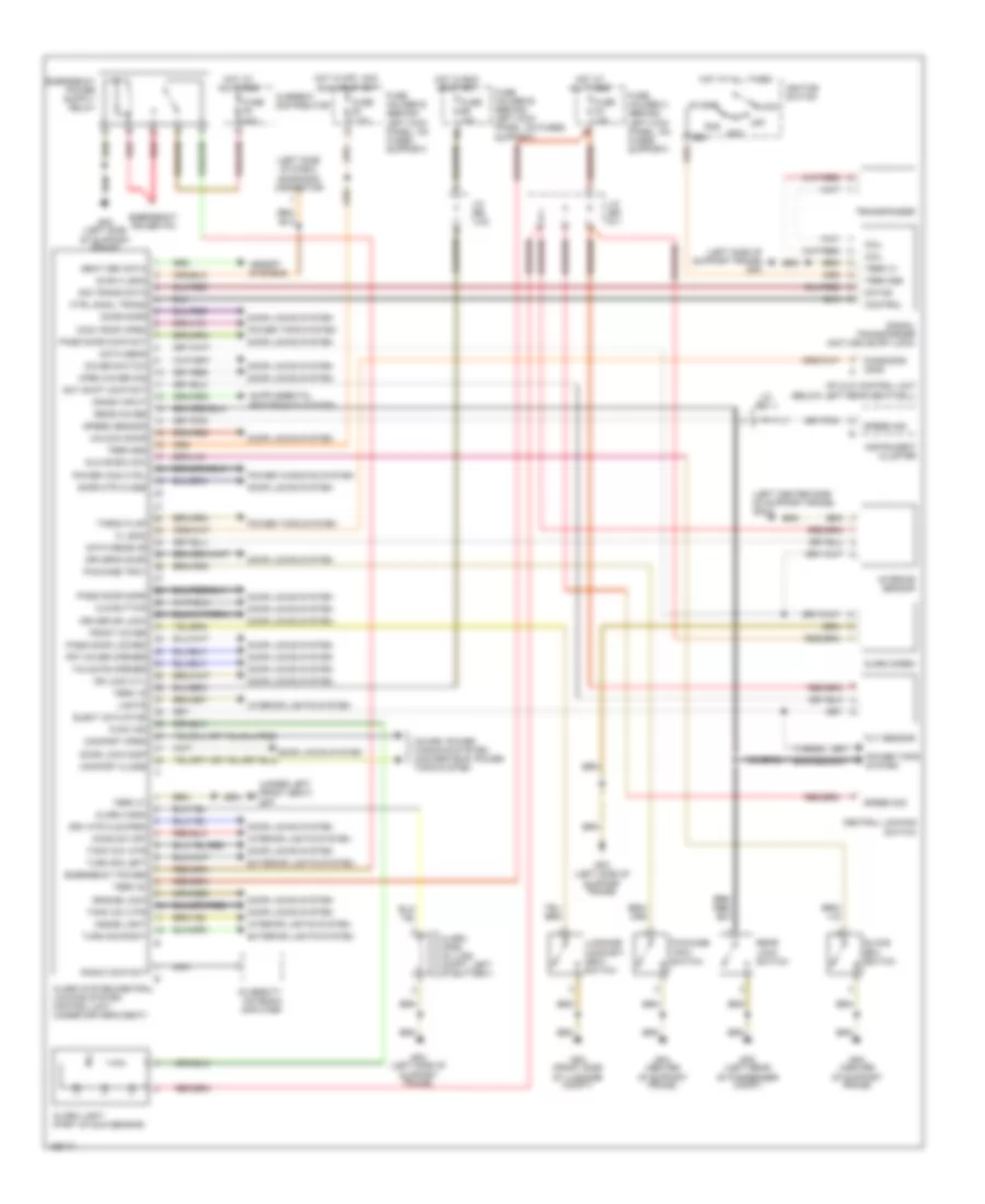
INTERIOR LIGHTS Interior Lights Wiring Diagram, Early Production (1 of 2) for Porsche 911 Turbo 2005 List of elements for Interior Lights Wiring Diagram, Early Production (1 of 2) for Porsche 911 Turbo 2005: 63 (4 leds) (under left front seat) (under left front seat) gp7 Ashtray light Blinds switch (targa) Central locking switch Cigar lighter Dim lamp bulb Dim led term 31d Dim led term 58d Engine compartment cover opener switch Exterior lamps circuit Fuse a5 15a Fuse b10 15a Fuse c3 15a Fuse e10 15a Fuse holder a (on fuses support) Fuse holder b (on fuses support) Fuse holder c (on fuses support) Fuse holder e (on fuses support) Gp4 (center of support frame) Gp6 (under right front seat) Gp7 Gp7 (under left front seat) Hazard warning light switch Head Hot at all times Hot in run or start Ignition switch Instrument cluster Intermittent wiper switch J/c (bs 10/1) J/c (bs 15) J/c (bs 5/1) J/c (bs 5/2) J/c (bs 7) J/c (bs 9/1) Key-in ignition switch L/r Left front power window switch Left rear power window switch (cabrio) Left seat heater control unit Left seat heater switch Light switch Luggage compartment cover opener switch Memory switch Off P30 Park Power top switch (cabrio) Psm on/off switch Rear window defogger switch Rear window wiper switch Right front power window switch Right rear power window switch (cabrio) Right seat heater control unit Right seat heater switch Sport exhaust system relay Sport exhaust system switch Sun sensor Targa flap switch (targa) Targa roof switch (targa) Term 58 Interior Lights Wiring Diagram, Early Production (2 of 2) for Porsche 911 Turbo 2005 List of elements for Interior Lights Wiring Diagram, Early Production (2 of 2) for Porsche 911 Turbo 2005: 50 (center of support frame) gp4 (left center side of support frame) gp3/1 (left rear of luggage compt) gp8 (left side of lugg compt) gp2 Alarm/ central locking system control unit Anti-dazzle interior mirror orientation light Cons switch off Cover front Cover rear Door Door lk dr Door locked Door safe Dr side handle Driver's side door lock light Driver's side door lock module Driver's side door orientation light Engine compartment light Footwell light 1 Footwell light 2 Footwell light relay 1 Footwell light relay 2 Footwell light switch Front luggage compartment hood switch Front luggage compartment light Function ind Glove box light Gp3 (left side of support frame) Gp3/1 (left center side of support frame) Gp4 (center of support frame) Gp7 (under left front seat) Inside light Interior reading light Left inside door handle Left luggage compartment light (targa) Left make-up mirror Left outside door handle Lights Lock cyl close Memory system Pass side hand Passenger's side door lock light Passenger's side door lock module Passenger's side door orientation light Power windows system Rear engine compartment hood switch Right inside door handle Right luggage compartment light (targa) Right make-up mirror Right outside door handle
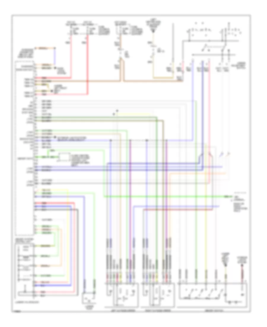
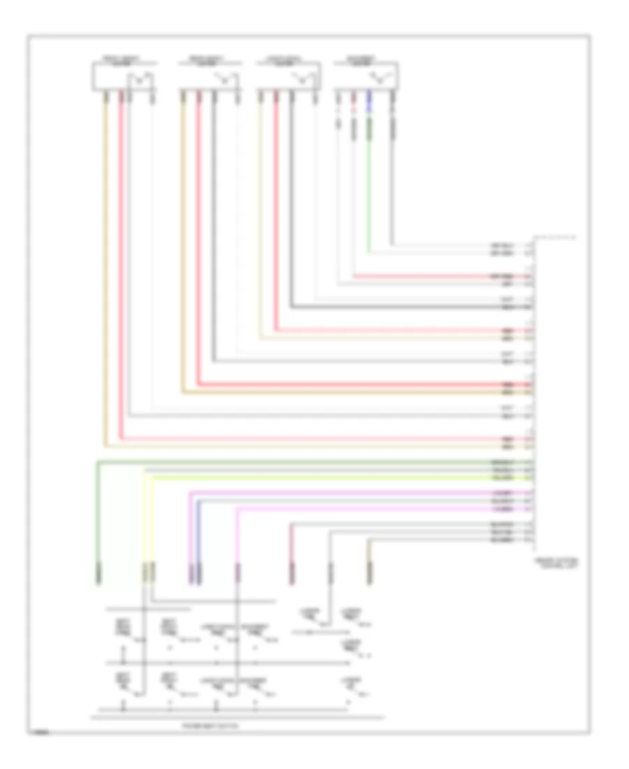
MEMORY SYSTEMS Memory Systems Wiring Diagram, Early Production (1 of 2) for Porsche 911 Turbo 2005 List of elements for Memory Systems Wiring Diagram, Early Production (1 of 2) for Porsche 911 Turbo 2005: 41 (left center side of support frame) gp3/1 (under left front seat) gp7 +5v Alarm/ central locking system control unit (under driver's seat) Backup sig Com mtr Diagnosis Diagnosis connector (below left side of dash) Door contact Door locks system Exterior lights system (backup lamps circuit) Fuse b5 7.5a Fuse e2 7.5a Fuse e3 30a Fuse holder b (on fuses support) Fuse holder e (on fuses support) Gfm-conn Hot at all times Hot in run or start Interior lights system J/c (bs 12) J/c (bs 16/2) Key code in Left outside mirror Lt/rt Lumbar pump Lumbar valve block Mem Memory data Memory switch Memory system control unit Mirror adjustment switch Pnk Radio or radio/ infosystem pcm 2 Red Right outside mirror Syst gnd Term 15 Term 30 Term 31 Up/dn Memory Systems Wiring Diagram, Early Production (2 of 2) for Porsche 911 Turbo 2005 List of elements for Memory Systems Wiring Diagram, Early Production (2 of 2) for Porsche 911 Turbo 2005: 19 Backrest back Backrest fwd Backrest motor Front height motor Longitudinal back Longitudinal fwd Longitudinal motor Lumbar back Lumbar down Lumbar fwd Lumbar up Memory system control unit Power seat switch Rear height motor Red Seat front down Seat front up Seat rear down Seat rear up
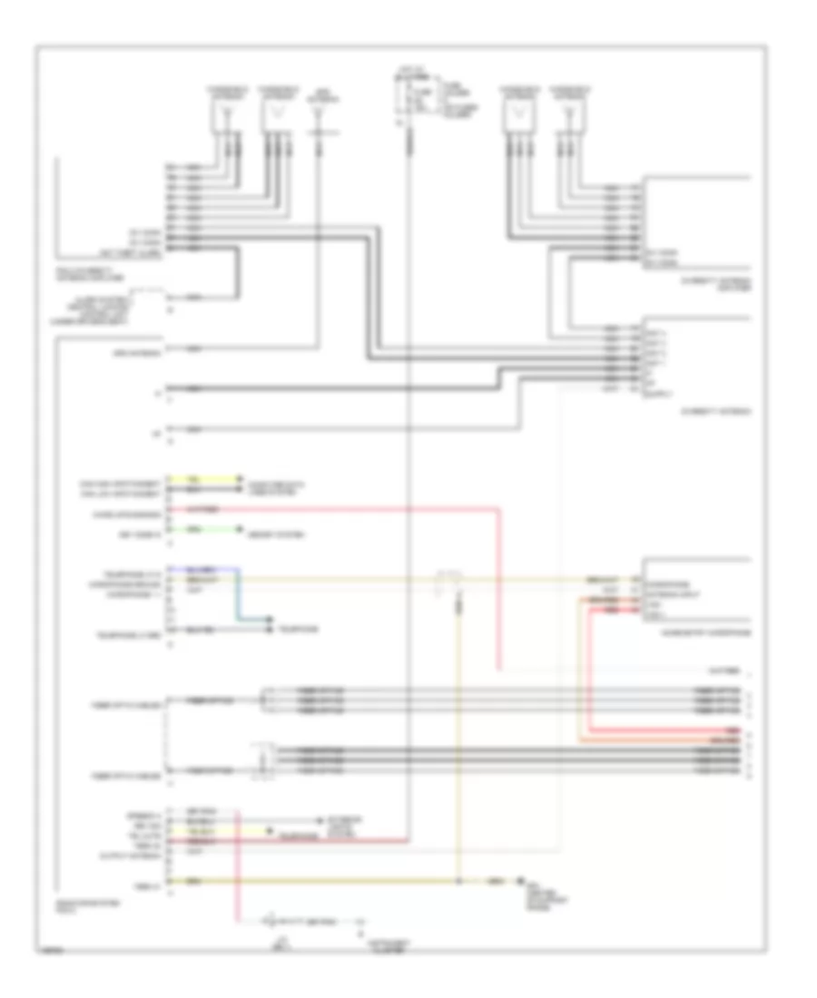
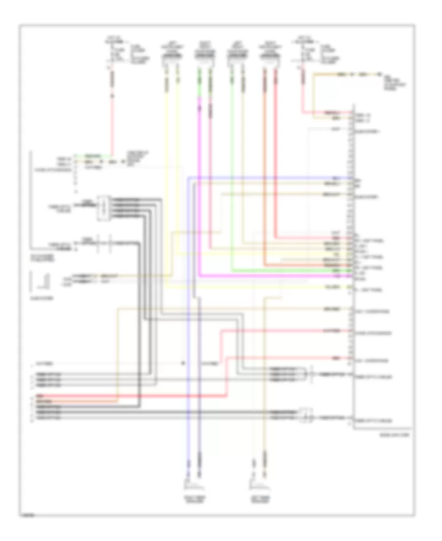
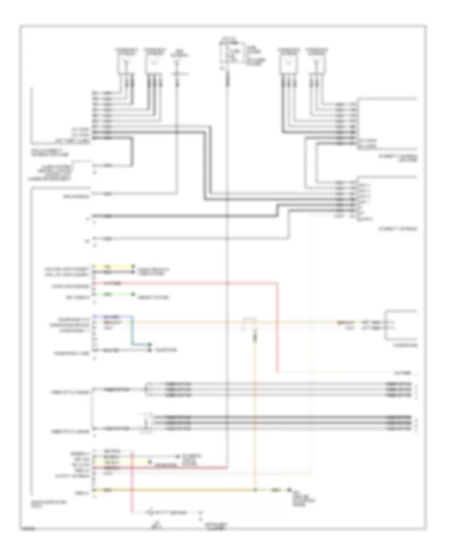
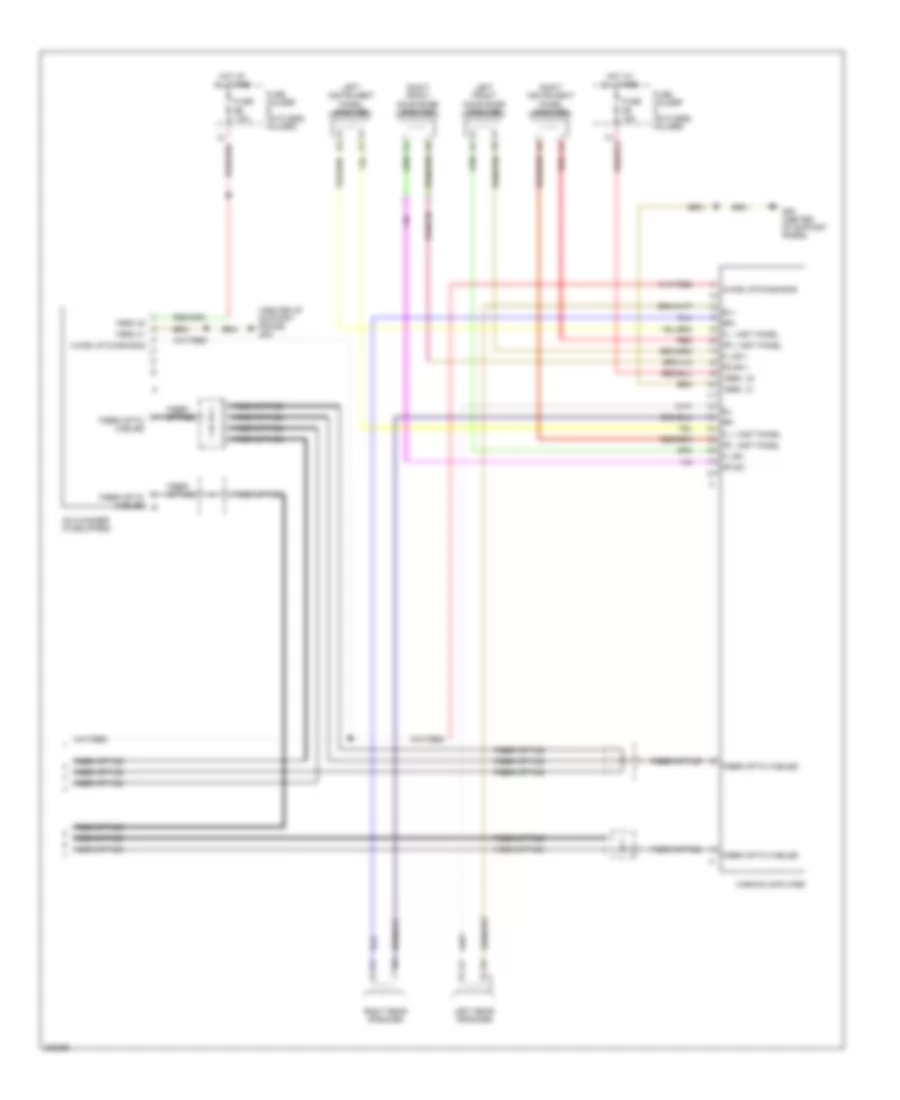
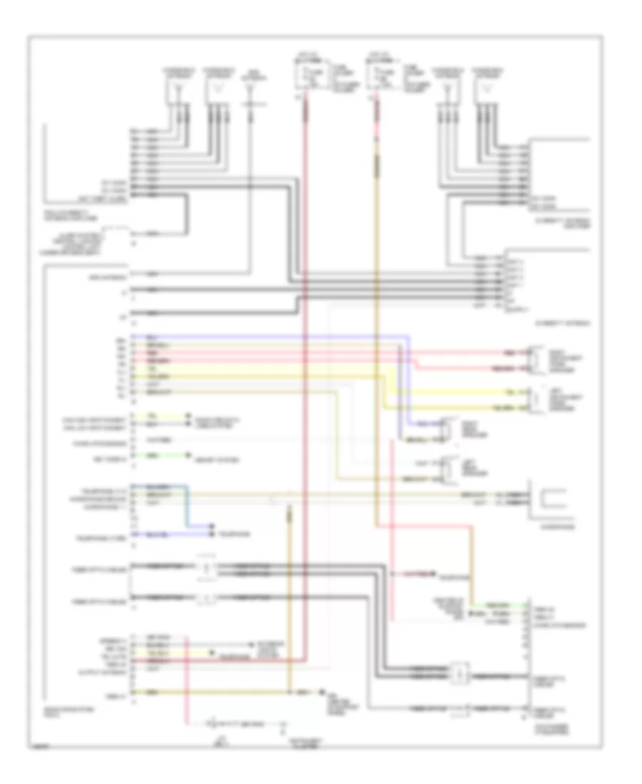
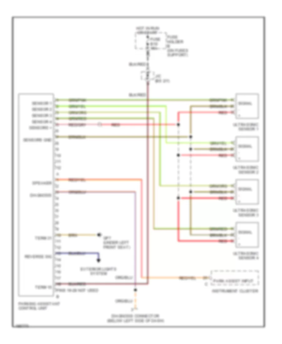
NAVIGATION Navigation Wiring Diagram, with Bose, Early Production (1 of 2) for Porsche 911 Turbo 2005 List of elements for Navigation Wiring Diagram, with Bose, Early Production (1 of 2) for Porsche 911 Turbo 2005: 46 Alarm system/ central locking control unit (under driver's seat) Ant 1 Ant 2 Ant 3 Ant 4 Ant theft alarm Antenna input Can high infotainment Can low infotainment Computer data lines system Div conn Diversity antenna Diversity antenna amplifier Exterior lights system Fiber optic cables Fiber optics Fuse d8 15a Fuse holder d (on fuses holder) Gp4 (center of support frame) Gps antenna Hot at all times Instrument cluster J/c (bs 1) Key code in Memory system Microphone Microphone 1 + Microphone ground Nca Noise entry microphone Output antenna Pcm 2 diversity antenna amplifier Radio/infosystem pcm 2 Red Rev sig Speedo a Tel mute Telephone Telephone lf grd Telephone lf in Term 30 Term 31 Vnc + Vnc - Wake up/diagnosis Windshield antenna Navigation Wiring Diagram, with Bose, Early Production (2 of 2) for Porsche 911 Turbo 2005 List of elements for Navigation Wiring Diagram, with Bose, Early Production (2 of 2) for Porsche 911 Turbo 2005: 45 (center of support frame) gp4 + sub - sub Bose amplifier Cd changer (if equipped) Fiber optic cables Fiber optic cables b Fiber optics Fl + inst panel Fl - inst panel Fl dr + Fl dr - Fr + inst panel Fr - inst panel Fr dr + Fr dr - Fuse d9 15a Fuse e6 7.5a Fuse holder d (on fuses holder) Fuse holder e (on fuses holder) Gp4 (center of support frame) Hot at all times Left front door bose speaker Left instrument panel speaker Left rear speaker Nca Red Right front door bose speaker Right instrument panel speaker Right rear speaker Rl+ Rl- Rr+ Rr- Subwoofer Subwoofer + Subwoofer - Term 30 Term 31 Term 30 Term 31 Vnc + microphone Vnc - microphone Wake up diagnosis Wake up/diagnosis Navigation Wiring Diagram, with Harman, Early Production (1 of 2) for Porsche 911 Turbo 2005 List of elements for Navigation Wiring Diagram, with Harman, Early Production (1 of 2) for Porsche 911 Turbo 2005: 41 Alarm system/ central locking control unit (under driver's seat) Ant 1 Ant 2 Ant 3 Ant 4 Ant theft alarm Can high infotainment Can low infotainment Computer data lines system Div conn Diversity antenna Diversity antenna amplifier Exterior lights system Fiber optic cables Fiber optics Fuse d8 15a Fuse holder d (on fuses holder) Gp4 (center of support frame) Gps antenna Hot at all times Instrument cluster J/c (bs 1) Key code in Memory system Microphone Microphone 1 + Microphone ground Nca Output antenna Pcm 2 diversity antenna amplifier Radio/infosystem pcm 2 Rev sig Speedo a Tel mute Telephone Telephone lf grd Telephone lf in Term 30 Term 31 Wake up/diagnosis Windshield antenna Navigation Wiring Diagram, with Harman, Early Production (2 of 2) for Porsche 911 Turbo 2005 List of elements for Navigation Wiring Diagram, with Harman, Early Production (2 of 2) for Porsche 911 Turbo 2005: 37 (center of support frame) gp4 Cd changer (if equipped) Fiber optic cables Fiber optic cables b Fiber optics Fl + inst panel Fl - inst panel Fl dr + Fl dr - Fr + inst panel Fr - inst panel Fr dr + Fr dr - Fuse d9 15a Fuse e6 7.5a Fuse holder d (on fuses holder) Fuse holder e (on fuses holder) Gp4 (center of support frame) Harman amplifier Hot at all times Left front door bose speaker Left instrument panel speaker Left rear speaker Red Right front door bose speaker Right instrument panel speaker Right rear speaker Rl+ Rl- Rr+ Rr- Term 30 Term 31 Term 30 Term 31 Wake up diagnosis Wake up/diagnosis Navigation Wiring Diagram, without Bose & Harman, Early Production for Porsche 911 Turbo 2005 List of elements for Navigation Wiring Diagram, without Bose & Harman, Early Production for Porsche 911 Turbo 2005: 59 (center of support frame) gp4 Alarm system/ central locking control unit (under driver's seat) Ant 1 Ant 2 Ant 3 Ant 4 Ant theft alarm Can high infotainment Can low infotainment Cd changer (if equipped) Computer data lines system Div conn Diversity antenna Diversity antenna amplifier Exterior lights system Fiber optic cables Fiber optics Fl+ Fl- Fr+ Fr- Fuse d8 15a Fuse e6 7.5a Fuse holder d (on fuses holder) Fuse holder e (on fuses holder) Gp4 (center of support frame) Gps antenna Hot at all times Instrument cluster J/c (bs 1) Key code in Left instrument panel speaker Left rear speaker Memory system Microphone Microphone 1 + Microphone ground Nca Output antenna Pcm 2 diversity antenna amplifier Radio/infosystem pcm 2 Red Rev sig Right instrument panel speaker Right rear speaker Rl+ Rl- Rr+ Rr- Speedo a Tel mute Telephone Telephone lf grd Telephone lf in Term 30 Term 31 Wake up diagnosis Wake up/diagnosis Windshield antenna Parking Assistant Wiring Diagram, Early Production for Porsche 911 Turbo 2005 List of elements for Parking Assistant Wiring Diagram, Early Production for Porsche 911 Turbo 2005: 28 Diagnosis Diagnosis connector (below left side of dash) Exterior lights system Fuse b10 15a Fuse holder b (on fuses support) Gp7 (under left front seat) Hot in run or start Instrument cluster J/c (bs 2/1) Park assist input Parking assistant control unit Pins 19-28 not used Red Reverse sig Sensor 1 Sensor 2 Sensor 3 Sensor 4 Sensors + Sensors gnd Signal Speaker Term 15 Term 31 Ultrasonic sensor 1 Ultrasonic sensor 2 Ultrasonic sensor 3 Ultrasonic sensor 4
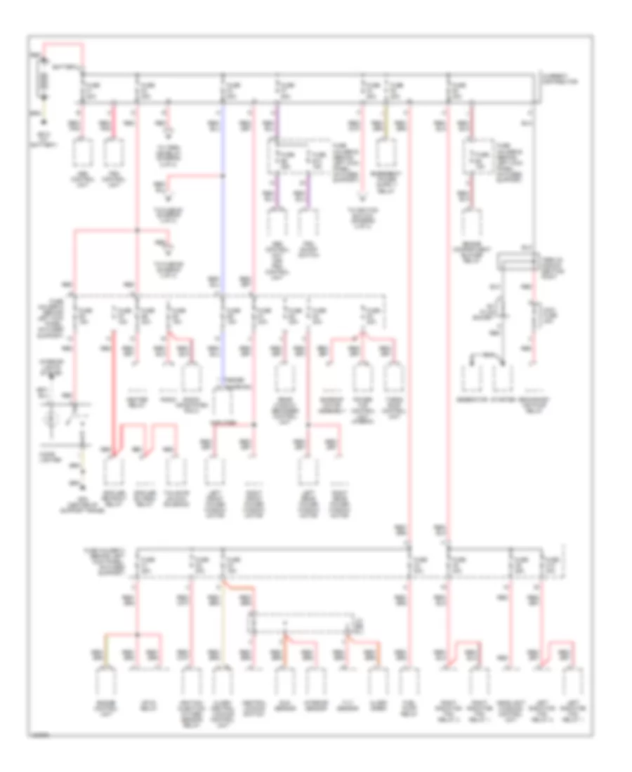
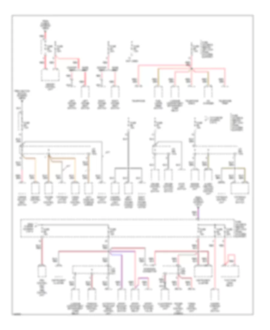
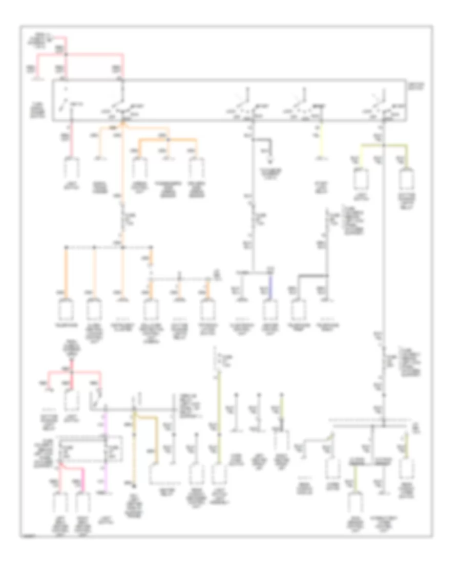
POWER DISTRIBUTION Power Distribution Wiring Diagram, Early Production (1 of 3) for Porsche 911 Turbo 2005 List of elements for Power Distribution Wiring Diagram, Early Production (1 of 3) for Porsche 911 Turbo 2005: 86 A (bose) A (harman) Abs control unit Abs control unit (or) psm control unit Alarm siren Alarm/ central locking control unit Amplifier B+ plug socket Battery Central locking switch Cigar lighter Current distributor Engine compartment blower relay Engine control unit Fuel pump relay Fuse b4 15a Fuse c1 25a Fuse c10 40a Fuse c2 30a Fuse c3 15a Fuse c4 30a Fuse c8 40a Fuse c9 25a Fuse d1 30a Fuse d2 30a Fuse d3 30a Fuse d4 30a Fuse d5 15a Fuse d6 30a Fuse d7 15a Fuse d8 15a Fuse d9 15a Fuse e10 15a Fuse e9 25a Fuse f1 50a Fuse f2 80a Fuse f3 80a Fuse f4 80a Fuse f5 80a Fuse f6 80a Fuse f7 50a Fuse holder b (behind left kick panel, on fuses support) Fuse holder c (behind left kick panel, on fuses support) Fuse holder d (behind left kick panel, on fuses support) Fuse holder e (behind left kick panel, on fuses support) Generator Gp13 (at battery) Gp4 (center of support frame) Headlight washing control unit Heater relay Ignition/ injection/ oxygen sensor relay Interior lights system Interior sensor J/c (bs 9/1) Left front power window motor Left radiator fan relay 1 Left radiator fan relay 2 Left rear power window motor Maxi fuse 40a Mfi-di relay Power top control unit (cabrio) Psm control unit Psm on/off switch Radio Radio/ infosystem pcm 2 Rear window defogger control unit Red Red/ pnk Right front power window motor Right radiator fan relay 1 Right radiator fan relay 2 Right rear power window motor Secondary air pump relay Spoiler extend relay Spoiler retract relay Starter Sun sensor Sunroof motor assembly Tailgate unlock solenoid Targa roof control unit Term 30 discon- necting point Tilt sensor To fuse b1 (diagram 3 of 3) To fuse e2 (diagram 3 of 3) To ignition switch (diagram 2 of 3) To term xe relay (diagram 2 of 3) Power Distribution Wiring Diagram, Early Production (2 of 3) for Porsche 911 Turbo 2005 List of elements for Power Distribution Wiring Diagram, Early Production (2 of 3) for Porsche 911 Turbo 2005: 68 (not used) A/t Alarm/ central locking control unit Anti- dazzling interior mirror Automatic headlamp beam control unit Back-up light switch Base seat Cd changer Climatronic control unit Comfort seat Cruise control clutch switch Cruise control main switch Diagnosis connector Engine control unit From fuse b8 (diagram 3 of 3) From fuse f2 (diagram 1 of 3) From fuse f3 (diagram 1 of 3) From ignition switch (diagram 2 of 3) Fuel vapor reed switch Fuse b1 15a Fuse b10 15a Fuse b2 15a Fuse b3 25a Fuse b5 7.5a Fuse b6 15a Fuse b7 15a Fuse b8 15a Fuse b9 15a Fuse e2 7.5a Fuse e3 30a Fuse e4 30a Fuse e5 7.5a Fuse e6 7.5a Fuse holder b (behind left kick panel, on fuses support) Fuse holder e (behind left kick panel, on fuses support) Hazard/ warning light switch Instrument cluster J/c (bs 13/2) J/c (bs 14/2) J/c (bs 16/2) J/c (bs 2/1) J/c (bs 9/2) Left front power window motor Left power seat switch Luggage compartment entrapment timer relay M/t Memory control unit Mirror adjust- ment switch Nca Parking assistant control unit Power top control unit Power top control unit (cabrio) Psm control unit (or) abs control unit Red Right front power window motor Right power seat switch Sport exhaust system relay Sport exhaust system switch Sport exhaust system valve Stop light switch Targa roof control unit Telephone Telephone e-box Telephone prep Tiptronic control unit Tiptronic lifting switch To fuse b9 (diagram 3 of 3) Two-tone horn relay Power Distribution Wiring Diagram, Early Production (3 of 3) for Porsche 911 Turbo 2005 List of elements for Power Distribution Wiring Diagram, Early Production (3 of 3) for Porsche 911 Turbo 2005: 63 86s Acc Airbag control unit Alarm/ central locking control unit Climatronic control unit Daytime running light relay Daytime running lights relay Driver's side airbag sensor From fuse f2 (diagram 1 of 3) From fuse f4 d (diagram 1 of 3) Fuse a6 25a Fuse a7 25a Fuse c6 25a Fuse c7 7.5a Fuse e1 7.5a Fuse e7 7.5a Fuse e8 7.5a Fuse holder a (behind left kick panel, on fuses support) Fuse holder c (behind left kick panel, on fuses support) Fuse holder e (behind left kick panel, on fuses support) G3/1 (left center side of support frame) Heater control unit Heater relay Ignition switch Instrument cluster Intermittent wiper control unit J/c (bs 13/1) J/c (bs 14/1) Key-in Left heated spray jet Left seat heater control unit Light switch Light switch light assembly Lock Nca Nse Off Passenger's side airbag sensor Rain sensor control unit Rear window defogger control unit Rear window module Rear window wiper switch Red Right heated spray jet Right seat heater control unit Rollover protection control unit (cabrio) Run Signal trans- former Start Start lock relay Telephone Telephone e-box Telephone prep Term xe relay (left kick panel, on relay support 1) Tiptronic lifting switch To fuse b5 (diagram 3 of 3) Turn signal dimmer switch W/ a/c W/ rain sensor W/o a/c W/o rain sensor Wipe/ wash switch Wiper motor
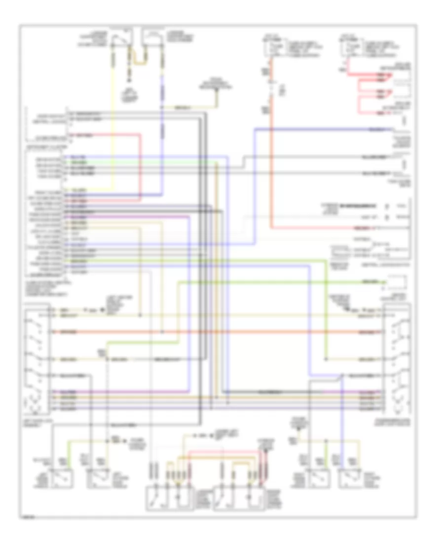
POWER DOOR LOCKS Power Door Locks Wiring Diagram, Early Production for Porsche 911 Turbo 2005 List of elements for Power Door Locks Wiring Diagram, Early Production for Porsche 911 Turbo 2005: 53 (center of support frame) gp4 (left center side of support frame) gp3/1 (under left front seat) gp7 Alarm system/ central locking system control unit (under driver's seat) Central locking Central locking switch Cls closed Cover open dis Cover open sw Door contact Door lk dr Dr lock disp Drive motor Driver door Drvr door safe Engine compt cover opener switch Front cover Frt cover drive Fuse c3 15a Fuse d7 15a Fuse holder c (behind left kick panel, on fuses support) Fuse holder d (behind left kick panel, on fuses support) Gp2 (left of luggage compt) Hot at all times Instrument cluster Interior lights system J/c (bs 9/1) Left door lock assembly Left inside door handle Left outside door handle Lock cyl close Luggage compartment hood opener Luggage compartment switch (cover closed) Luggage compt cover opener switch Memory control unit Pass door Pass door safe Pass side hand Passenger's side door lock module Power windows system Red Resistor (180 ohm) Right inside door handle Right outside door handle Safe mtr cls Spoiler extend relay Spoiler retract relay Tailgate opener Tailgate unlock solenoid Tank cover Tank cover drive Trunk entrapment release system Unlock door
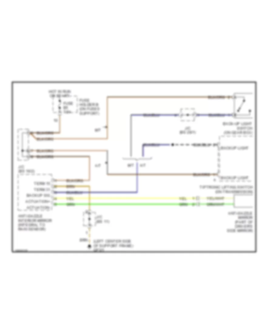
POWER MIRRORS Auto Anti-dazzling Mirror Wiring Diagram, Early Production for Porsche 911 Turbo 2005 List of elements for Auto Anti-dazzling Mirror Wiring Diagram, Early Production for Porsche 911 Turbo 2005: 19 (left center side of support frame) gp3/1 A/t Actuation+ Actuation- Anti-dazzle interior mirror (integral to rain sensor) Anti-dazzle mirror (part of driver's side mirror) Back-up light switch (on gear box) Backup light Backup sig Fuse b5 7.5a Fuse holder b (on fuses support) Hot in run or start J/c (bs 11) J/c (bs 16/2) J/c (bs 28/1) M/t Term 15 Term 31 Tiptronic lifting switch (on transmission) Power Mirrors Wiring Diagram, Early Production for Porsche 911 Turbo 2005 List of elements for Power Mirrors Wiring Diagram, Early Production for Porsche 911 Turbo 2005: 15 Anti- dazzle Anti-dazzle mirror circuit Defogger system Driver's side power mirror Fuse b5 7.5a Fuse holder b (on fuses support) Gp3/1 (left center side of support frame) Hot in run or start J/c (bs 12) J/c (bs 16/2) Left/ right Mirror adjustment switch Passenger's side power mirror Red Up/ down
POWER SEATS Comfort Seats Wiring Diagram, Early Production for Porsche 911 Turbo 2005 List of elements for Comfort Seats Wiring Diagram, Early Production for Porsche 911 Turbo 2005: 21 Back Down Front seat cushion height control motor Fuse e3 30a Fuse e4 30a Fuse holder e (on fuses support) Fwd Gp6 (under right front seat) Gp7 (under left front seat) High Hot at all times Left power seat Lumbar pressure switch Lumbar pump motor Lumbar valve block Power seat switch Rear seat cushion height control motor Red Right power seat Seat back forward control motor Seat backrest control motor Power Seats Wiring Diagram, Early Production for Porsche 911 Turbo 2005 List of elements for Power Seats Wiring Diagram, Early Production for Porsche 911 Turbo 2005: 22 Back Backrest control motor Backrest heating element Fuse a6 25a Fuse e3 30a Fuse e4 30a Fuse holder a (behind left kick panel, on fuses support) Fuse holder e (behind left kick panel, on fuses support) Fwd Gp6 (under right front seat) Gp7 (under left front seat) Hot at all times Hot w/term xe relay energized Interior lights system Left power seat switch Left seat heater control unit Left seat heater switch Red Right power seat switch Right seat heater control unit Right seat heater switch Seat heating element
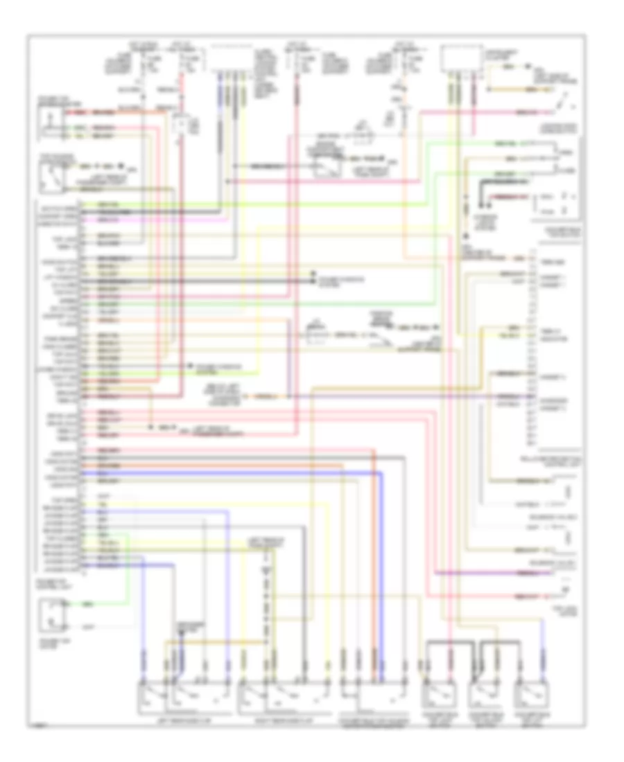
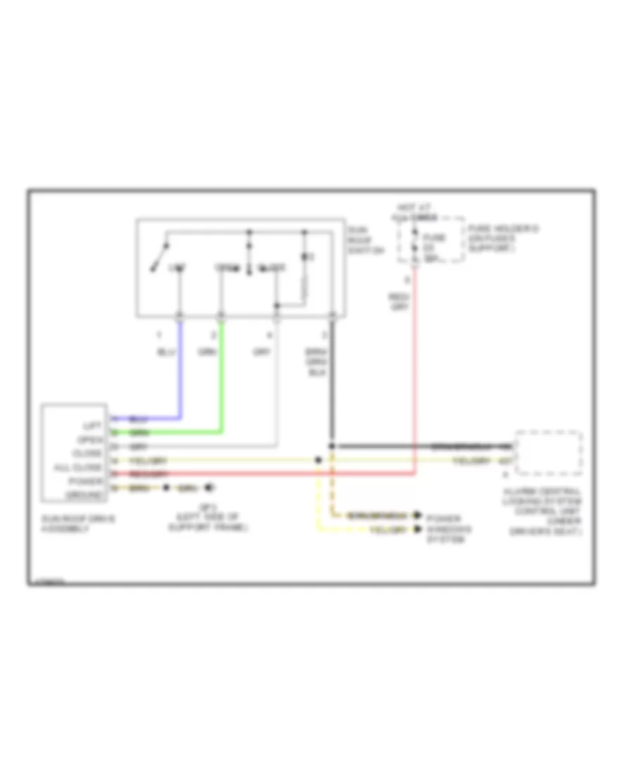
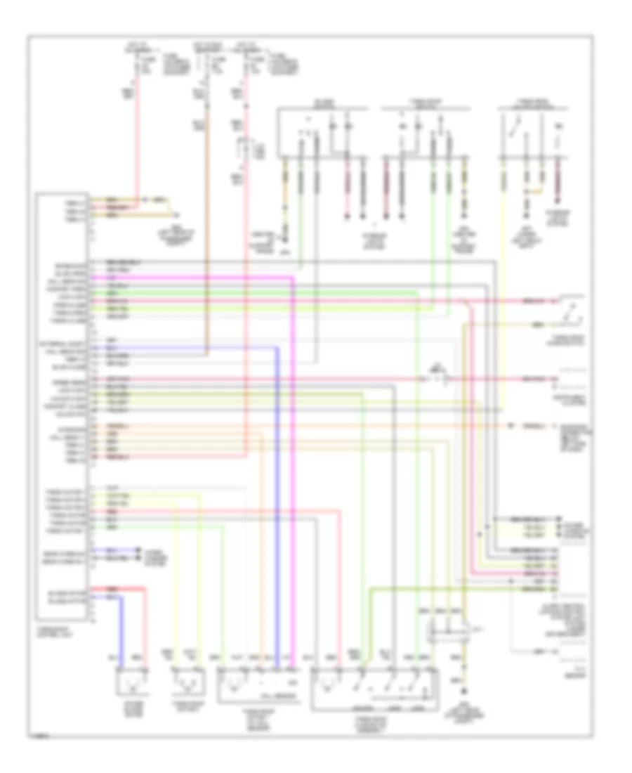
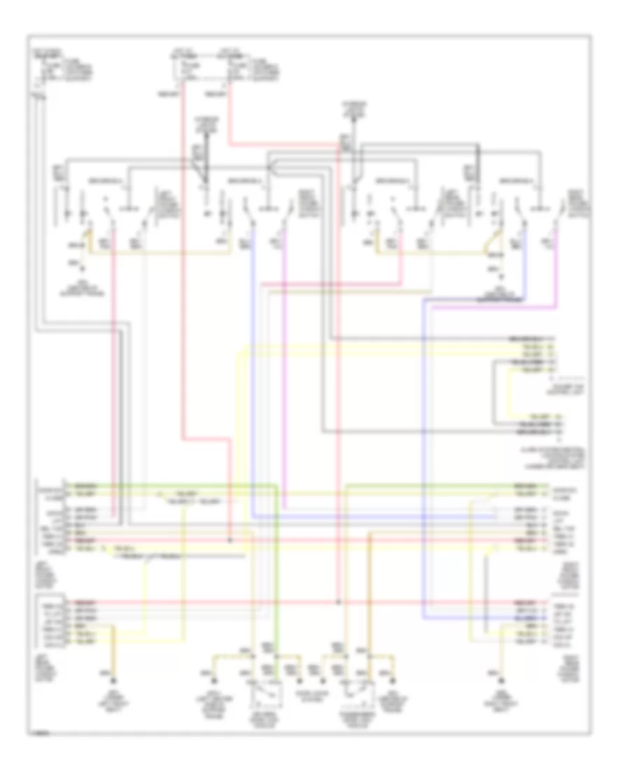
POWER TOP/SUNROOF Convertible Top Wiring Diagram, Early Production for Porsche 911 Turbo 2005 List of elements for Convertible Top Wiring Diagram, Early Production for Porsche 911 Turbo 2005: 82 (below left side of dash) diagnosis connector (left rear of pass compt) (left rear of passenger compt) Alarm/ central locking system control unit (under driver's seat) Close Comfort cls Comfort open Convertible top housing motor/potentiometer Convertible top lift switch Convertible top lock switch Convertible top switch Convertible top unlock switch Convt ind Cu alarm Defogger system Diagnosis Drive lock Drive unlk Engine compartment hood switch Fuse b1 15a Fuse b5 7.5a Fuse d3 30a Fuse e1 7.5a Fuse holder b (on fuses support) Fuse holder d (on fuses support) Fuse holder e (on fuses support) Gp3 (left side of support frame) Gp4 (center of support frame) Gp8 Ground Hardtop stat Hood switch Hot at all times Hot in run or start Indicator Instrument cluster Interior lights system J/c (bs 1) J/c (bs 13/1) J/c (bs 6/1) J/c (bs 9/2) K lead Left rear side flap Lift window Locking hook micro-switch Lower window Lr side flap Magnet 1 Magnet 2 Nca Open Park brake Parking brake switch Power top control unit Power top motor Power top potentiometer Power windows system Red Right rear side flap Rollover protection control unit Rr side flap Solenoid valve 1 Solenoid valve 2 Speed Sw close Switch open Term 15 Term 30 Term 31 Term 86s Top closed Top housing micro-switch Top lift Top lock Top lock motor Top open Top poti Top unlk Vdkd closed Vdkd motor Vdkd poti Vdkd sig Sunroof Wiring Diagram, Early Production for Porsche 911 Turbo 2005 List of elements for Sunroof Wiring Diagram, Early Production for Porsche 911 Turbo 2005: 14 Alarm/ central locking system control unit (under driver's seat) All close Close Fuse d3 30a Fuse holder d (on fuses support) Gp3 (left side of support frame) Ground Hot at all times Lift Open Power Power windows system Sun roof drive assembly Sun roof switch Targa Roof Wiring Diagram, Early Production for Porsche 911 Turbo 2005 List of elements for Targa Roof Wiring Diagram, Early Production for Porsche 911 Turbo 2005: 64 (center of support frame) Alarm/ central locking control system unit system (under driver's seat) Blind close Blind open Blinds motor Blinds switch Close Comfort close Comfort open Diagnosis Diagnosis connector (below left side of dash) Enable sig External elect Fuse b1 15a Fuse b5 7.5a Fuse d3 30a Fuse holder b (on fuses support) Fuse holder d (on fuses support) Gp4 Gp4 (center of support frame) Gp7 (under left front seat) Gp8 (left rear of passenger compt) Hall sens gnd Hall sens sig Hall sens v+ Hall sensor Hot at all times Hot in run or start Instrument cluster Interior lights system J/c (bs 1) J/c (bs 9/2) J/c 1 Lock Lock m-sw Open Open/close Power blinds motor Power windows system Rear wiper rly Rear wiper sw Red Sig Speed sens Targa close Targa motor Targa motor 1 Targa motor 2 Targa open Targa roof closing aid assembly Targa roof control unit Targa roof micro-switch Targa roof motor 1 (w/ hall sensor) Targa roof motor 2 Targa roof switch Targa roof unlock switch Term 15 Term 30 Term 31 Tilt sensor Unlock Unlock m-sw Unlock sw Wiper/ washer system
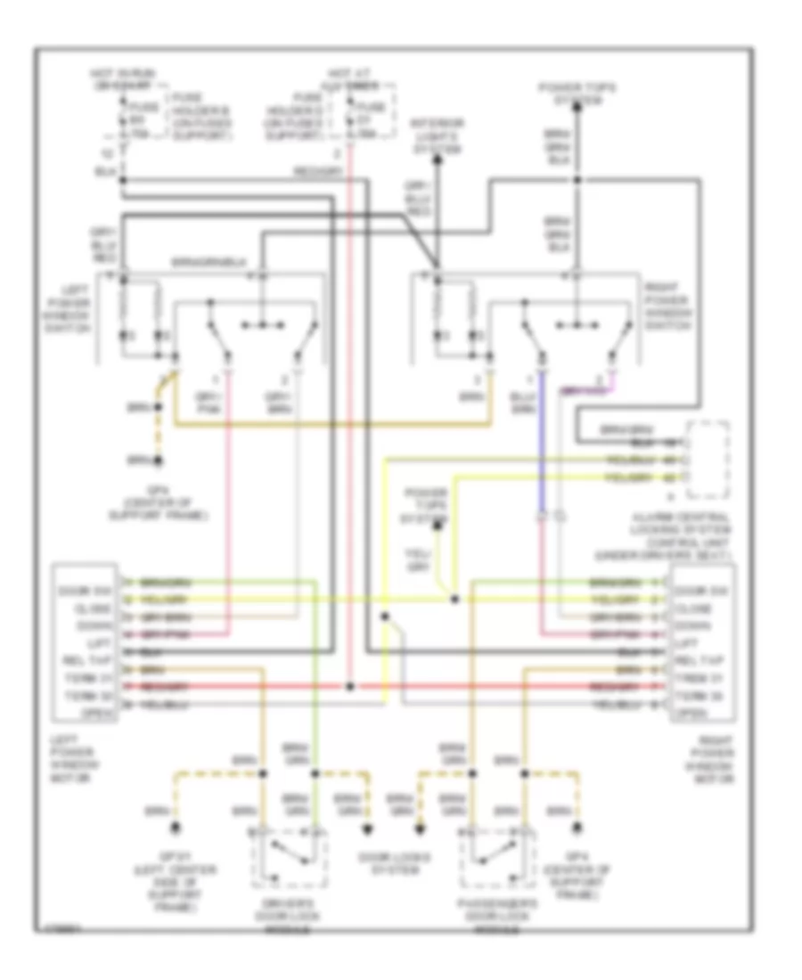
POWER WINDOWS Power Windows Wiring Diagram, Cabriolet, Early Production for Porsche 911 Turbo 2005 List of elements for Power Windows Wiring Diagram, Cabriolet, Early Production for Porsche 911 Turbo 2005: 38 Alarm system/central locking system control unit (under driver's seat) Close Com cl Com op Door locks system Door sw Down Driver's door lock module Fuse b6 15a Fuse d1 30a Fuse d4 30a Fuse holder b (on fuses support) Fuse holder d (on fuses support) Gp3/1 (left center side of support frame) Gp4 (center of support frame) Gp6 (under right front seat) Gp7 (under left front seat) Hot at all times Hot in run or start Interior lights system Left front power window motor Left front power window switch Left rear power window motor Left rear power window switch Let dn Lift Open Passenger's door lock module Power top control unit Rel tap Right front power window motor Right front power window switch Right rear power window motor Right rear power window switch Term 30 Term 31 To lift Trem 31 Power Windows Wiring Diagram, Coupe, Early Production for Porsche 911 Turbo 2005 List of elements for Power Windows Wiring Diagram, Coupe, Early Production for Porsche 911 Turbo 2005: 27 Alarm/ central locking system control unit (under driver's seat) Close Door locks system Door sw Down Driver's door lock module Fuse b6 15a Fuse d1 30a Fuse holder b (on fuses support) Fuse holder d (on fuses support) Gp3/1 (left center side of support frame) Gp4 (center of support frame) Hot at all times Hot in run or start Interior lights system Left power window motor Left power window switch Lift Open Passenger's door lock module Power tops system Rel tap Right power window motor Right power window switch Term 30 Term 31 Trem 31
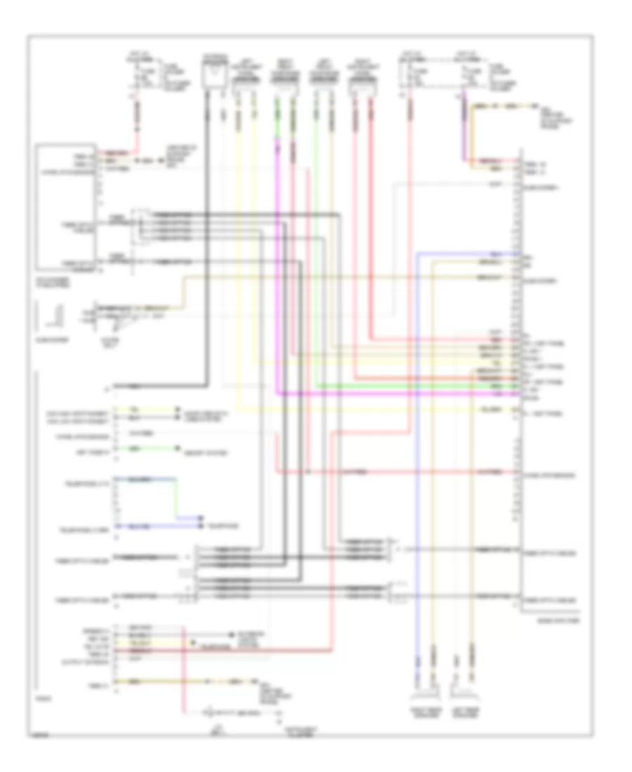
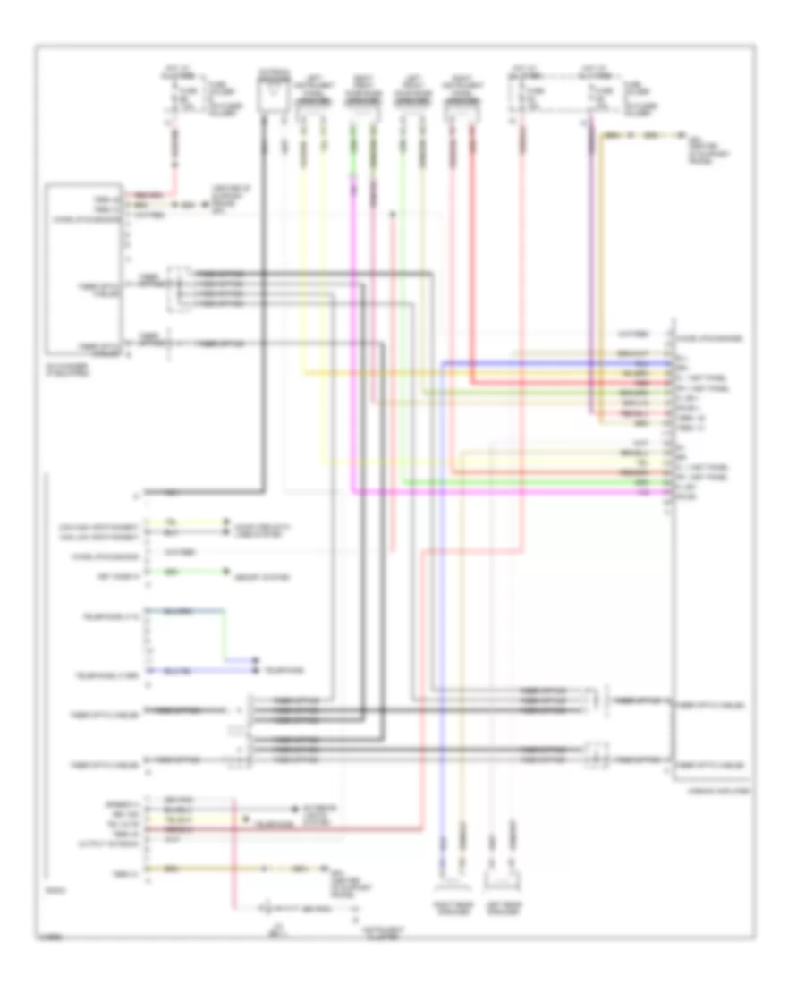
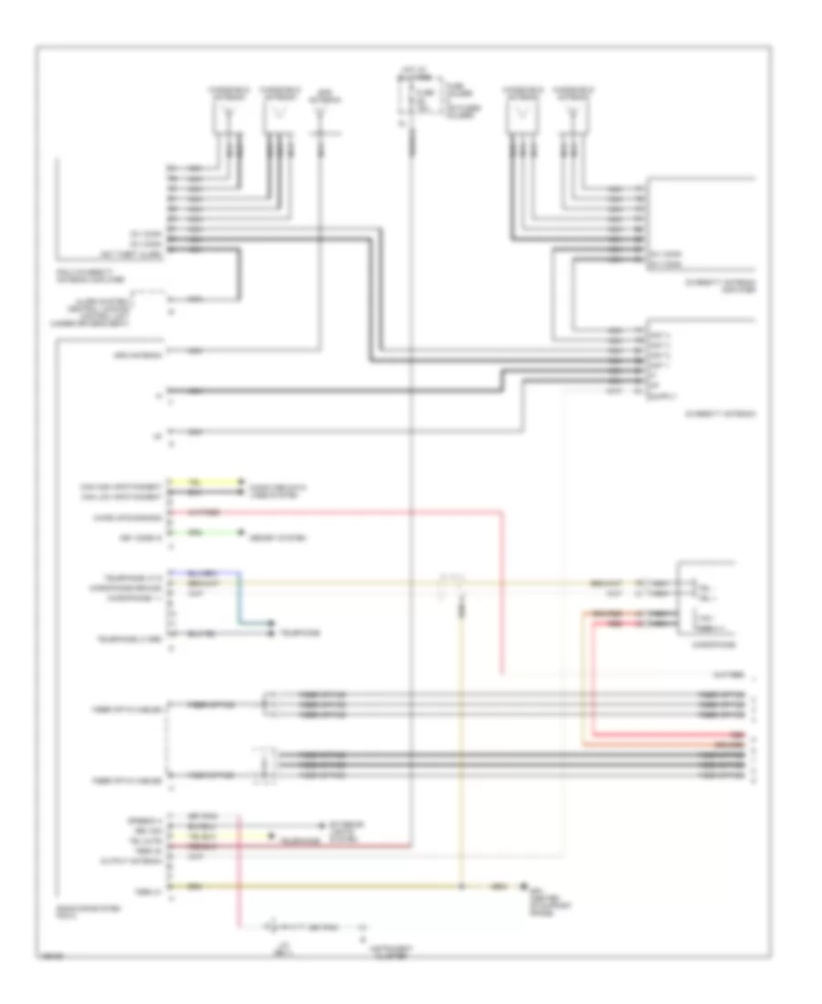
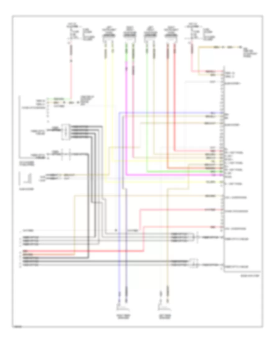
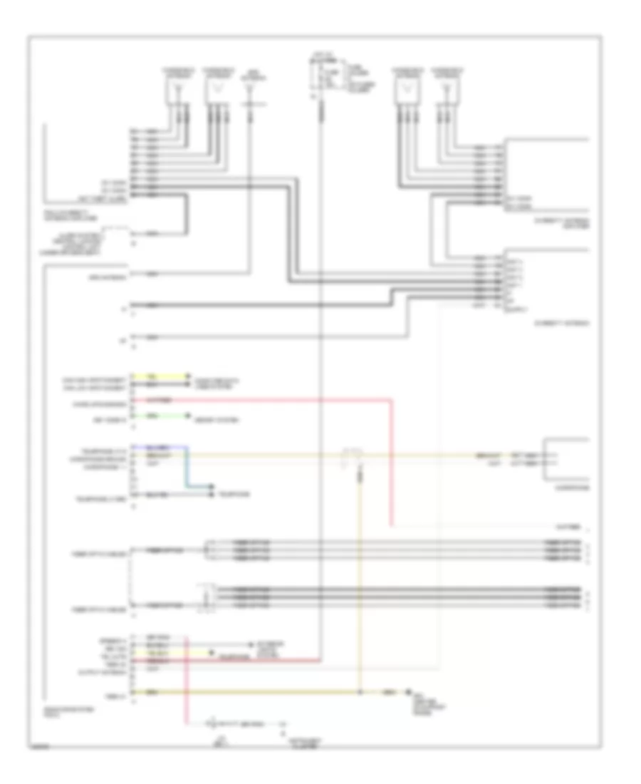
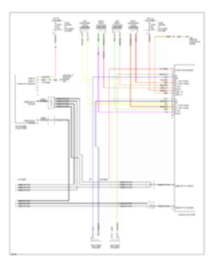
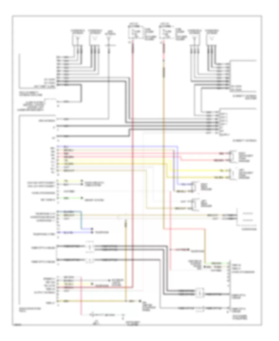
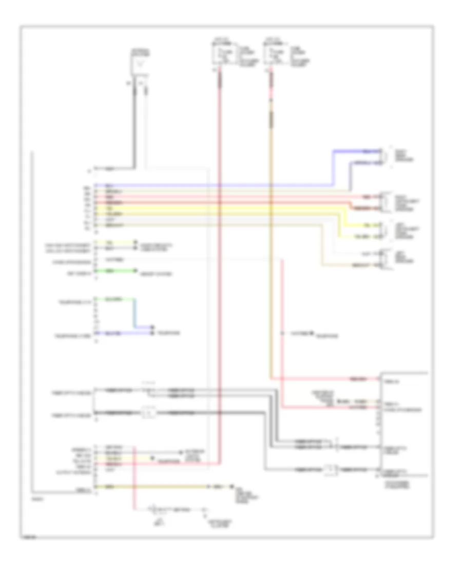
RADIO Radio Wiring Diagram, with Bose without Navigation, Early Production for Porsche 911 Turbo 2005 List of elements for Radio Wiring Diagram, with Bose without Navigation, Early Production for Porsche 911 Turbo 2005: 62 (center of support frame) gp4 + sub - sub Antenna amplifier Bose amplifier Can high infotainment Can low infotainment Cd changer (if equipped) Computer data lines system Coupe only Exterior lights system Fiber optic cables Fiber optic cables b Fiber optics Fl + inst panel Fl - inst panel Fl dr + Fl dr - Fr + inst panel Fr - inst panel Fr dr + Fr dr - Fuse d8 15a Fuse d9 15a Fuse e6 7.5a Fuse holder d (on fuses holder) Fuse holder e (on fuses holder) Gp4 (center of support frame) Hot at all times Instrument cluster J/c (bs 1) Key code in Left front door bose speaker Left instrument panel speaker Left rear speaker Memory system Nca Output antenna Radio Red Rev sig Right front door bose speaker Right instrument panel speaker Right rear speaker Rl+ Rl- Rr+ Rr- Speedo a Subwoofer Subwoofer + Subwoofer - Tel mute Telephone Telephone lf grd Telephone lf in Term 30 Term 31 Term 30 Term 31 Wake up diagnosis Wake up/diagnosis Radio Wiring Diagram, with Harman without Navigation, Early Production for Porsche 911 Turbo 2005 List of elements for Radio Wiring Diagram, with Harman without Navigation, Early Production for Porsche 911 Turbo 2005: 56 (center of support frame) gp4 Antenna amplifier Can high infotainment Can low infotainment Cd changer (if equipped) Computer data lines system Exterior lights system Fiber optic cables Fiber optic cables b Fiber optics Fl + inst panel Fl - inst panel Fl dr + Fl dr - Fr + inst panel Fr - inst panel Fr dr + Fr dr - Fuse d8 15a Fuse d9 15a Fuse e6 7.5a Fuse holder d (on fuses holder) Fuse holder e (on fuses holder) Gp4 (center of support frame) Harman amplifier Hot at all times Instrument cluster J/c (bs 1) Key code in Left front door bose speaker Left instrument panel speaker Left rear speaker Memory system Nca Output antenna Radio Red Rev sig Right front door bose speaker Right instrument panel speaker Right rear speaker Rl+ Rl- Rr+ Rr- Speedo a Tel mute Telephone Telephone lf grd Telephone lf in Term 30 Term 31 Term 30 Term 31 Wake up diagnosis Wake up/diagnosis Radio Wiring Diagram, with Navigation, with Bose, Early Production (1 of 2) for Porsche 911 Turbo 2005 List of elements for Radio Wiring Diagram, with Navigation, with Bose, Early Production (1 of 2) for Porsche 911 Turbo 2005: 46 Alarm system/ central locking control unit (under driver's seat) Ant 1 Ant 2 Ant 3 Ant 4 Ant theft alarm Can high infotainment Can low infotainment Computer data lines system Div conn Diversity antenna Diversity antenna amplifier Exterior lights system Fiber optic cables Fiber optics Fuse d8 15a Fuse holder d (on fuses holder) Gp4 (center of support frame) Gps antenna Hot at all times Instrument cluster J/c (bs 1) Key code in Memory system Microphone Microphone 1 + Microphone ground Nca Output antenna Pcm 2 diversity antenna amplifier Radio/infosystem pcm 2 Red Rev sig Speedo a Tel + Tel - Tel mute Telephone Telephone lf grd Telephone lf in Term 30 Term 31 Vnc + Vnc - Wake up/diagnosis Windshield antenna Radio Wiring Diagram, with Navigation, with Bose, Early Production (2 of 2) for Porsche 911 Turbo 2005 List of elements for Radio Wiring Diagram, with Navigation, with Bose, Early Production (2 of 2) for Porsche 911 Turbo 2005: 45 (center of support frame) gp4 + sub - sub Bose amplifier Cd changer (if equipped) Fiber optic cables Fiber optic cables b Fiber optics Fl + inst panel Fl - inst panel Fl dr + Fl dr - Fr + inst panel Fr - inst panel Fr dr + Fr dr - Fuse d9 15a Fuse e6 7.5a Fuse holder d (on fuses holder) Fuse holder e (on fuses holder) Gp4 (center of support frame) Hot at all times Left front door bose speaker Left instrument panel speaker Left rear speaker Nca Red Right front door bose speaker Right instrument panel speaker Right rear speaker Rl+ Rl- Rr+ Rr- Subwoofer Subwoofer + Subwoofer - Term 30 Term 31 Term 30 Term 31 Vnc + microphone Vnc - microphone Wake up diagnosis Wake up/diagnosis Radio Wiring Diagram, with Navigation, with Harman, Early Production (1 of 2) for Porsche 911 Turbo 2005 List of elements for Radio Wiring Diagram, with Navigation, with Harman, Early Production (1 of 2) for Porsche 911 Turbo 2005: 41 Alarm system/ central locking control unit (under driver's seat) Ant 1 Ant 2 Ant 3 Ant 4 Ant theft alarm Can high infotainment Can low infotainment Computer data lines system Div conn Diversity antenna Diversity antenna amplifier Exterior lights system Fiber optic cables Fiber optics Fuse d8 15a Fuse holder d (on fuses holder) Gp4 (center of support frame) Gps antenna Hot at all times Instrument cluster J/c (bs 1) Key code in Memory system Microphone Microphone 1 + Microphone ground Nca Output antenna Pcm 2 diversity antenna amplifier Radio/infosystem pcm 2 Rev sig Speedo a Tel mute Telephone Telephone lf grd Telephone lf in Term 30 Term 31 Wake up/diagnosis Windshield antenna Radio Wiring Diagram, with Navigation, with Harman, Early Production (2 of 2) for Porsche 911 Turbo 2005 List of elements for Radio Wiring Diagram, with Navigation, with Harman, Early Production (2 of 2) for Porsche 911 Turbo 2005: 37 (center of support frame) gp4 Cd changer (if equipped) Fiber optic cables Fiber optic cables b Fiber optics Fl + inst panel Fl - inst panel Fl dr + Fl dr - Fr + inst panel Fr - inst panel Fr dr + Fr dr - Fuse d9 15a Fuse e6 7.5a Fuse holder d (on fuses holder) Fuse holder e (on fuses holder) Gp4 (center of support frame) Harman amplifier Hot at all times Left front door bose speaker Left instrument panel speaker Left rear speaker Red Right front door bose speaker Right instrument panel speaker Right rear speaker Rl+ Rl- Rr+ Rr- Term 30 Term 31 Term 30 Term 31 Wake up diagnosis Wake up/diagnosis Radio Wiring Diagram, with Navigation, without Bose & Harman, Early Production for Porsche 911 Turbo 2005 List of elements for Radio Wiring Diagram, with Navigation, without Bose & Harman, Early Production for Porsche 911 Turbo 2005: 59 (center of support frame) gp4 Alarm system/ central locking control unit (under driver's seat) Ant 1 Ant 2 Ant 3 Ant 4 Ant theft alarm Can high infotainment Can low infotainment Cd changer (if equipped) Computer data lines system Div conn Diversity antenna Diversity antenna amplifier Exterior lights system Fiber optic cables Fiber optics Fl+ Fl- Fr+ Fr- Fuse d8 15a Fuse e6 7.5a Fuse holder d (on fuses holder) Fuse holder e (on fuses holder) Gp4 (center of support frame) Gps antenna Hot at all times Instrument cluster J/c (bs 1) Key code in Left instrument panel speaker Left rear speaker Memory system Microphone Microphone 1 + Microphone ground Nca Output antenna Pcm 2 diversity antenna amplifier Radio/infosystem pcm 2 Red Rev sig Right instrument panel speaker Right rear speaker Rl+ Rl- Rr+ Rr- Speedo a Tel mute Telephone Telephone lf grd Telephone lf in Term 30 Term 31 Wake up diagnosis Wake up/diagnosis Windshield antenna Radio Wiring Diagram, without Navigation without Bose & Harman, Early Production for Porsche 911 Turbo 2005 List of elements for Radio Wiring Diagram, without Navigation without Bose & Harman, Early Production for Porsche 911 Turbo 2005: 45 (center of support frame) gp4 Antenna amplifier Can high infotainment Can low infotainment Cd changer (if equipped) Computer data lines system Exterior lights system Fiber optic cables Fiber optics Fl+ Fl- Fr+ Fr- Fuse d8 15a Fuse e6 7.5a Fuse holder d (on fuses holder) Fuse holder e (on fuses holder) Gp4 (center of support frame) Hot at all times Instrument cluster J/c (bs 1) Key code in Left instrument panel speaker Left rear speaker Memory system Nca Output antenna Radio Red Rev sig Right instrument panel speaker Right rear speaker Rl+ Rl- Rr+ Rr- Speedo a Tel mute Telephone Telephone lf grd Telephone lf in Term 30 Term 31 Wake up diagnosis Wake up/diagnosis
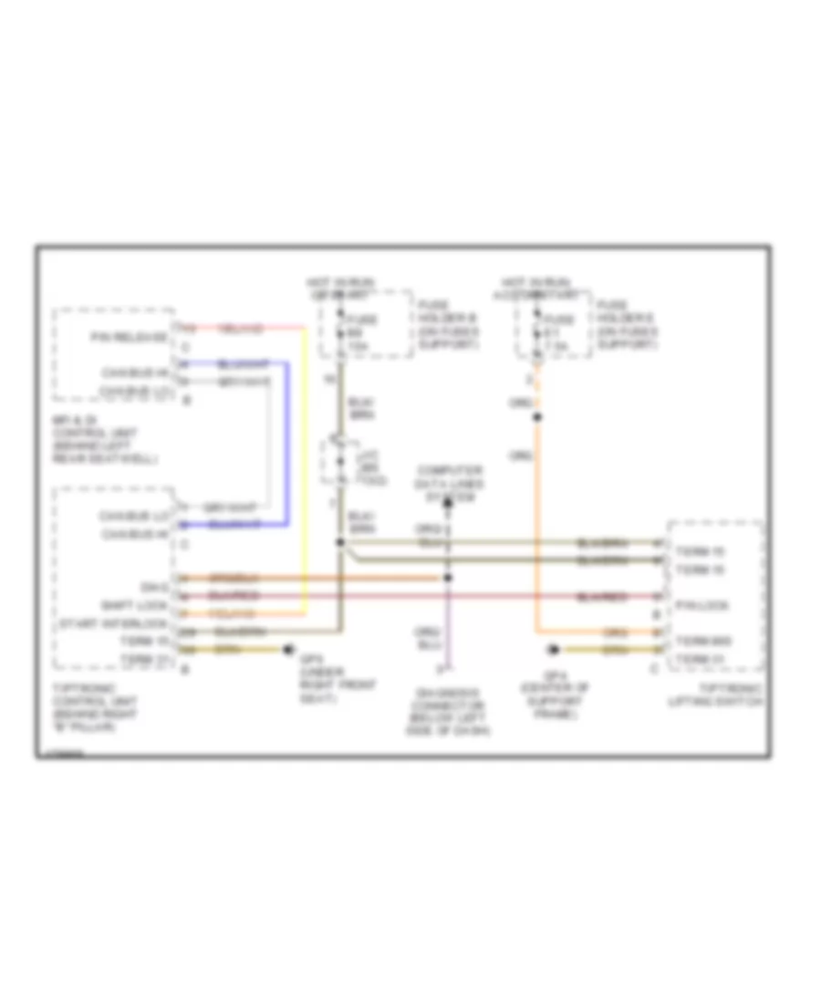
SHIFT INTERLOCK Shift Interlock Wiring Diagram, Early Production for Porsche 911 Turbo 2005 List of elements for Shift Interlock Wiring Diagram, Early Production for Porsche 911 Turbo 2005: 24 Can bus hi Can bus lo Computer data lines system Diag Diagnosis connector (below left side of dash) Fuse b8 15a Fuse e1 7.5a Fuse holder b (on fuses support) Fuse holder e (on fuses support) Gp4 (center of support frame) Gp6 (under right front seat) Hot in run or start Hot in run, acc or start J/c (bs 13/2) Mfi & di control unit (behind left rear seatwell) P/n lock P/n release Shift lock Start interlock Term 15 Term 31 Term 86s Tiptronic control unit (behind right "b" pillar) Tiptronic lifting switch
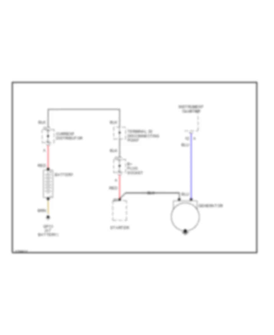
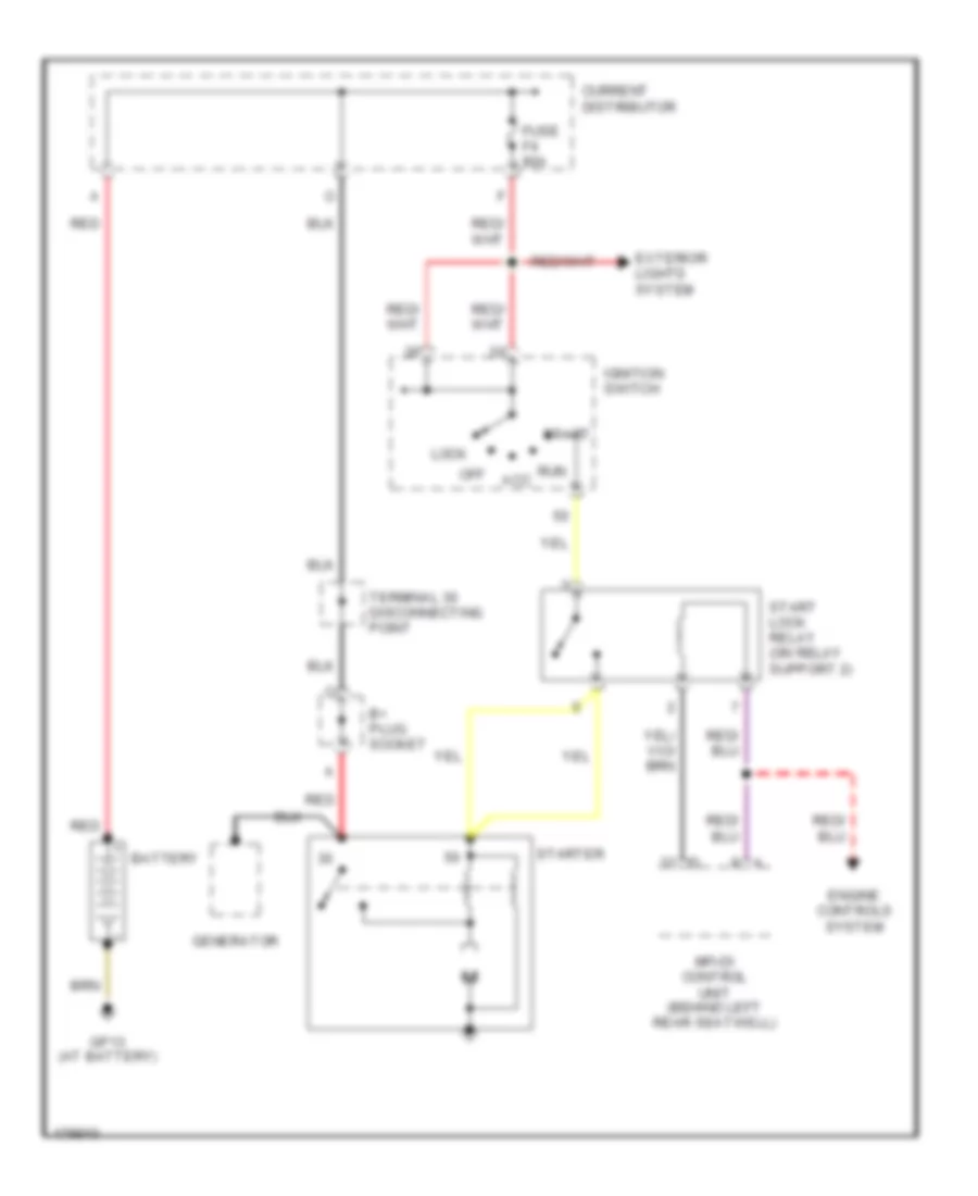
STARTING/CHARGING Charging Wiring Diagram, Early Production for Porsche 911 Turbo 2005 List of elements for Charging Wiring Diagram, Early Production for Porsche 911 Turbo 2005: 9 B+ plug socket Battery Current distributor Generator Gp13 (at battery) Instrument cluster Red Starter Terminal 30 disconnecting point Starting Wiring Diagram, Early Production for Porsche 911 Turbo 2005 List of elements for Starting Wiring Diagram, Early Production for Porsche 911 Turbo 2005: 19 Acc B+ plug socket Battery Current distributor Engine controls system Exterior lights system Fuse f4 80a Generator Gp13 (at battery) Ignition switch Lock Mfi-di control unit (behind left rear seatwell) Off Red Run Start Start lock relay (on relay support 2) Starter Terminal 30 disconnecting point
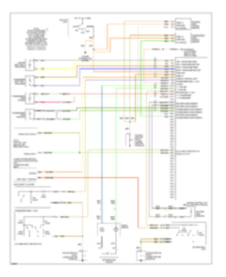
SUPPLEMENTAL RESTRAINTS Supplemental Restraints Wiring Diagram for Porsche 911 Turbo 2005 List of elements for Supplemental Restraints Wiring Diagram for Porsche 911 Turbo 2005: 96 + it driver + it passenger - it driver - it passenger 86s A10 A11 A12 A13 A14 A15 A16 A17 A18 A19 A20 A21 A22 A23 A24 A25 A26 A27 A28 A29 A3 diagnosis plug socket (below left side of dash) A30 A31 A32 A33 A34 A35 A36 A37 A38 A39 A40 A41 A42 A43 A44 A45 A46 A47 A48 A49 A50 Acc Air bag Air bag control unit (below center console) Air bag ground point (under center console) Airbag warning lamp Alarm system/central locking system control unit (under driver's seat) B21 B25 Child seat recognition Children seat recognition Crash input Crash output Crash shut-down Cu air bag D16 Driver seat belt tensioner Driver's belt lock Driver's side air bag Driver's side air bag sensor Driver's side side bag Driver's side sidebag Hot at all times Ignition lock Instrument cluster K lead Left tensioner feed Left tensioner return Lock Mfi-di control unit (behind left rear seatwell) Nca Note: shorting bridges on air bag control unit close when unit connector is disconnected from harness. shorting bridges connect pins: a1 & a2, a3 & a4, a6 & a7 a10 & a11, a13 & a14, a16 & a17, a18 & a19 Off Ohms Passenger seat belt tensioner Passenger's belt lock Passenger's side air bag Passenger's side air bag sensor Passenger's side side bag Passenger's side sidebag Pnk Power distribution system Right tensioner feed Right tensioner return Run Seat belt warning Spiral spring Start Term 31 Term 86s
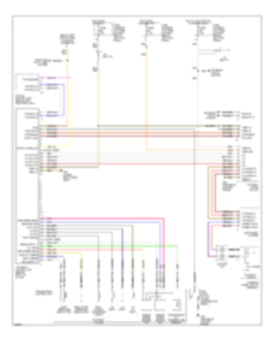
TRANSMISSION A/T Wiring Diagram, Early Production for Porsche 911 Turbo 2005 List of elements for A/T Wiring Diagram, Early Production for Porsche 911 Turbo 2005: 74 (below left side of dash) diagnosis connector 1-2/ 3-4 shift 1-2/3-4 sol 18 - 32 (not used) 2-3 shift 2-3 sol 3-4 shift 3-4 sol 8 - 24 (not used) Backup Backup 15 Can bus hi Can bus lo Cluster w0 Cluster w1 Cluster w3 Computer data lines system Contact unit Diag Eng speed sens Engine speed sensor (n2) Engine speed sensor (n3) Exterior lights system Fuse a6 15a Fuse b8 15a Fuse e1 7.5a Fuse holder a (on fuses support, behind left kick panel) Fuse holder b (on fuses support, behind left kick panel) Fuse holder e (on fuses support, behind left kick panel) Gp4 (center of support frame) Gp6 (under right front seat) Hot in run or start Hot in run, acc or start Hot w/ light switch in park or head Instrument cluster J/c (bs 10/1) J/c (bs 13/2) Kick down switch (under accelerator pedal) Kick-down M-program Mfi & di control unit (behind left rear seatwell) Modulat press Modulation pressure regulating Nca Oil temp P/n lock P/n release Pmw- torque converter lockup Pnk Pwm torque Sens return Shift lock Shift press Shift pressure regulating Solenoid valves Start interlock Steer ctrls Steering wheel switch assembly Term 15 Term 31 Term 51 Term 86s Tiptronic 1 Tiptronic 2 Tiptronic 3 Tiptronic control unit (behind right "b" pillar) Tiptronic lifting switch Tiptronic switch Transmission control unit Transmission oil temperature sensor W0 switch W1 switch W2 switch W3 switch
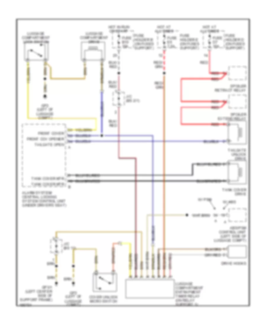
TRUNK, TAILGATE, FUEL DOOR Trunk, Tailgate, Fuel Door Wiring Diagram, Early Production A/T for Porsche 911 Turbo 2005 List of elements for Trunk, Tailgate, Fuel Door Wiring Diagram, Early Production A/T for Porsche 911 Turbo 2005: 30 Abs/psm control unit (left side of luggage compt) Alarm system/ central locking system control unit (under driver's seat) Cover unlock micro switch Drive hooks Front cov opener Front cover Fuse b10 15a Fuse d7 15a Fuse e6 7.5a Fuse holder b (on fuses support) Fuse holder d (on fuses support) Fuse holder e (on fuses support) Gp2 (left of luggage compt) Gp3/1 (left center side of support frame) Hot at all times Hot in run or start J/c (bs 11) J/c (bs 2/1) Luggage compartment drive Luggage compartment entrapment timer relay (on relay support 1) Luggage compartment lock switch Red Spoiler extend relay Spoiler retract relay Tailgate open Tailgate unlock drive Tank cover drive Tank cover mtr W/ abs W/ psm
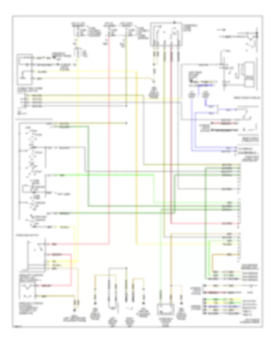
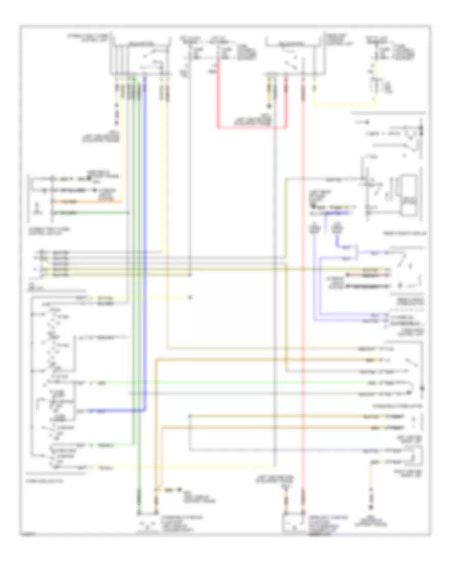
WIPER/WASHER Wiper/Washer Wiring Diagram, with Rain Sensor, Early Production for Porsche 911 Turbo 2005 List of elements for Wiper/Washer Wiring Diagram, with Rain Sensor, Early Production for Porsche 911 Turbo 2005: 58 (center of support frame) (left rear of pass compt) gp8 (not used) 31b 53a 53b 53c 53e 53i Actuation + Actuation - Anti-dazzle interior mirror Backup sig Fuse a9 15a Fuse c6 25a Fuse c9 25a Fuse holder a (on fuses support) Fuse holder c (on fuses support) Gp3 (left side of support frame) Gp3/1 (left center side of support frame) Gp4 Gp4 (center of support frame) Headlight washing control unit (relay support 1) Headlight washing fluid pump (on windshield washer fluid reservoir) Hot at all times Hot in acc or run Hot w/ low beams on Int Interior lights system Intermittent wiper control switch J/c (bs 10/2) J/c (bs 14/1) Left heated spray jet Mirrors system Nca Off R wiper relay R wiper sw Rain sensor Rain sensor control unit Rear window module Rear window wiper switch Red Right heated spray jet Solid state Targa roof control unit Term 15 Term 31 Tip sw Tip sw lo W/ targa roof W/o targa roof Washing Windshield washing fluid pump Windshield wiper motor Wipe/ wash Wipe/wash Wipe/wash switch Wiper/Washer Wiring Diagram, without Rain Sensor, Early Production for Porsche 911 Turbo 2005 List of elements for Wiper/Washer Wiring Diagram, without Rain Sensor, Early Production for Porsche 911 Turbo 2005: 51 (center of support frame) (left center side of support frame) (left rear of pass compt) gp8 31b 53a 53b 53c 53e 53i Fuse a9 15a Fuse c6 25a Fuse c9 25a Fuse holder a (on fuses support) Fuse holder c (on fuses support) Gp3 (left side of support frame) Gp3/1 Gp3/1 (left center side of support frame) Gp4 Gp4 (center of support frame) Headlight washing control unit Headlight washing fluid pump (on windshield washer fluid reservoir) Hot at all times Hot in acc or run Hot w/ low beams on Int Interior lights system Intermittent wiper control switch Intermittent wiper control unit J/c (bs 10/2) J/c (bs 14/1) Left heated spray jet Nca Off R wiper relay R wiper sw Rear window module Rear window wiper switch Red Right heated spray jet Solid state Targa roof control unit Tip sw Tip sw lo W/ targa roof W/o targa roof Washing Windshield washing fluid pump (left side of luggage compt) Windshield wiper motor Wipe/ wash Wipe/wash Wipe/wash switch