Diagram sections — 28 (43 total)
AIR CONDITIONING ANTI-LOCK BRAKES ANTI-THEFT BODY CONTROL MODULES COMPUTER DATA LINES COOLING FAN CRUISE CONTROL DEFOGGERS ELECTRONIC POWER STEERING ENGINE PERFORMANCE EXTERIOR LIGHTS GROUND DISTRIBUTION HEADLIGHTS HORN INSTRUMENT CLUSTER INTERIOR LIGHTS POWER DISTRIBUTION POWER DOOR LOCKS POWER MIRRORS POWER TOP/SUNROOF POWER WINDOWS RADIO SHIFT INTERLOCK STARTING/CHARGING SUPPLEMENTAL RESTRAINTS TRUNK, TAILGATE, FUEL DOOR WARNING SYSTEMS WIPER/WASHER
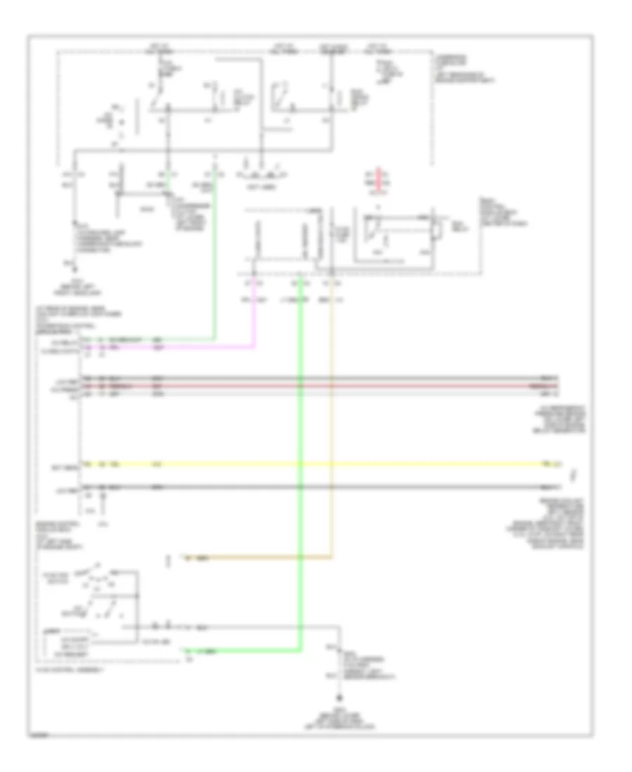
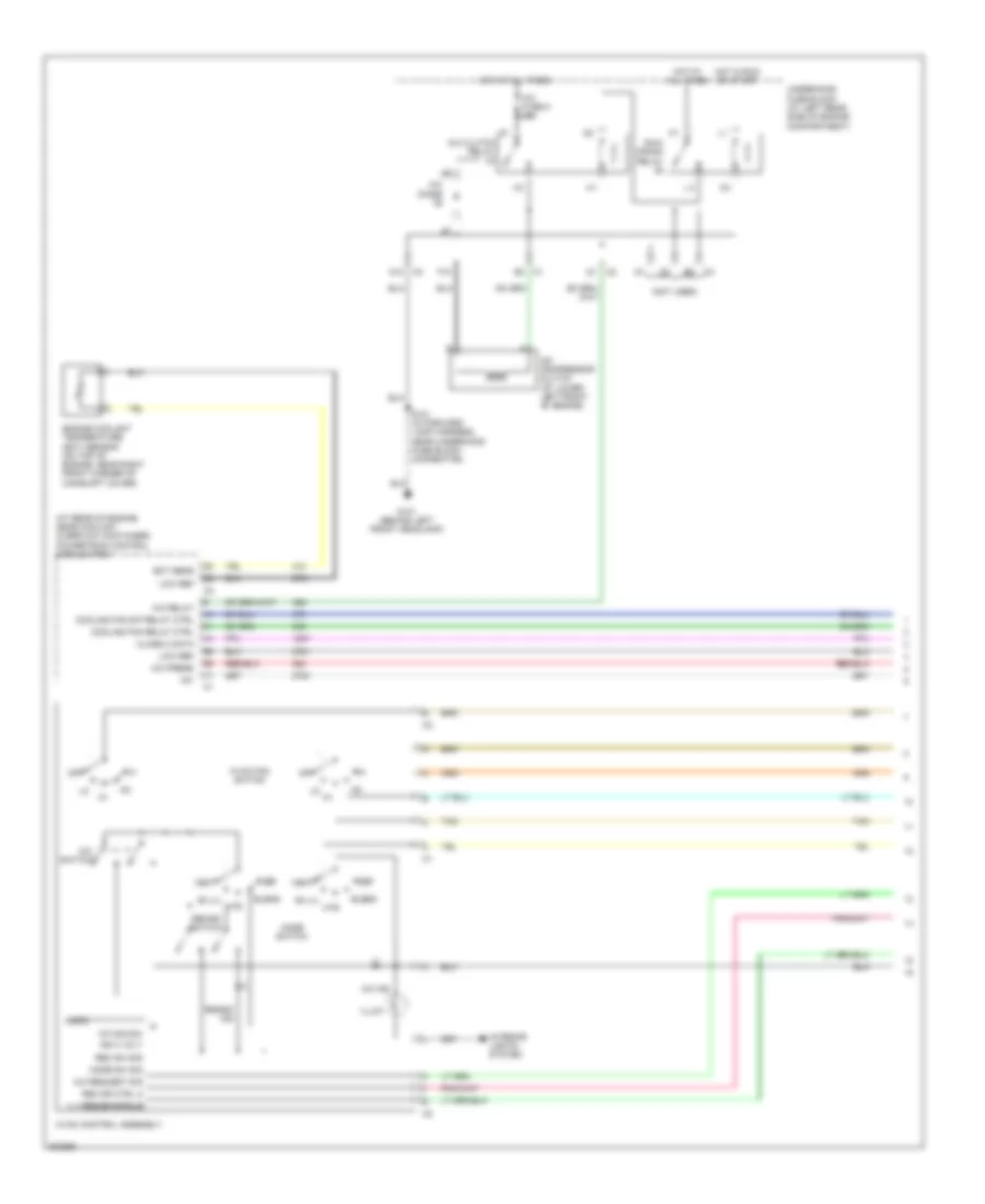
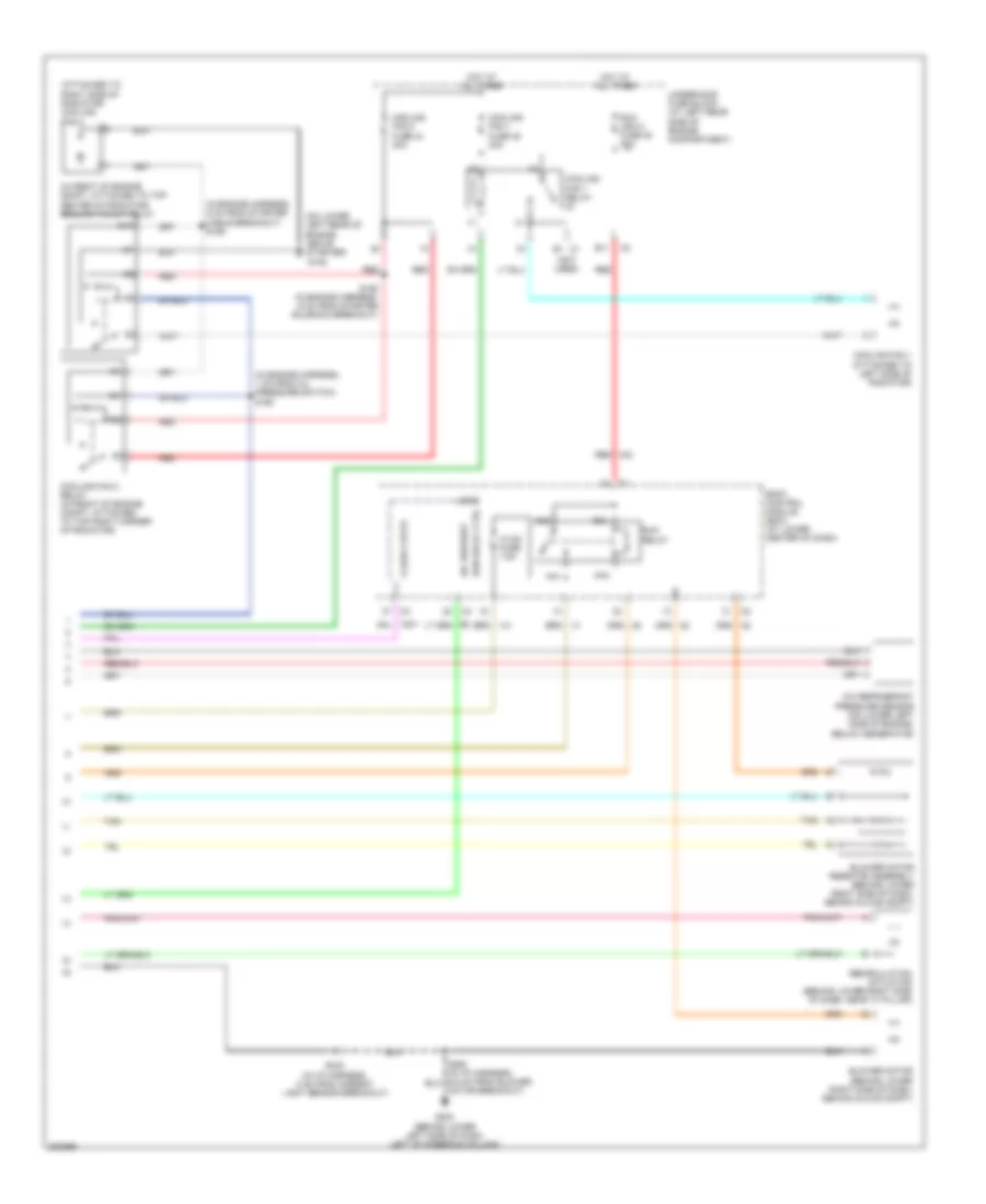
AIR CONDITIONING Compressor Wiring Diagram for Saturn Ion Red Line 2005 List of elements for Compressor Wiring Diagram for Saturn Ion Red Line 2005: 47 (at rear of engine, near coolant overflow container) (2.0l) powertrain control module (pcm) (not used) +5v 2.0l 2.2l A/c clutch relay A/c compressor clutch (at lower left front of engine) A/c diode A/c fuse 5 10a A/c on led A/c on/off A/c press A/c refrigerant pressure sensor (on lower left side of engine, below generator) A/c relay A/c request A/c switch A10 Aa1 Aa2 Aa3 Aa4 B11 Body control module (bcm) (at lower center of dash) Class 2 data Ect sens Engine control module (ecm) (2.2l) (at left side of engine compt) Engine coolant temperature (ect) sensor (2.0l: on top of engine, near right front corner of camshaft cover) (2.2l (vin f): on right rear side of engine, near exhaust manifold) F10 G101 (behind left front headlamp) G203 (behind lower left side of dash, left of steering column) Hot at all times Hot in run or start Hvac control assembly Hvac fan switch Hvac fuse 7.5a Ign 3 volt Logic Low ref Off Red Run (ign 3) fuse 48 30a Run relay Run relay ctrl Run/ crank relay S101 (in forward lamp harness, near underhood fuse block connector) S233 (in i/p harness, 5 cm from ambient light sensor breakout) Underhood fuse block (at left rear side of engine compartment) Manual A/C Wiring Diagram (1 of 2) for Saturn Ion Red Line 2005 List of elements for Manual A/C Wiring Diagram (1 of 2) for Saturn Ion Red Line 2005: 47 (at rear of engine, near coolant overflow container) powertrain control module (pcm) (not used) +5v A/c clutch relay A/c compressor clutch (at lower left front of engine) A/c diode A/c fuse 5 10a A/c ind A/c press A/c relay A/c request sig A/c sig sw A/c switch A10 Bi-lvl Blend Class 2 data Cooling fan relay ctrl Cooling fan s/p relay ctrl Def Ect sens Engine coolant temperature (ect) sensor (on top of engine, near right front corner of camshaft cover) F10 G101 (behind left front headlamp) Hot at all times Hot in run or start Htr Hvac control assembly Hvac fan switch Ign 3 volt Illum Interior lights system Logic Low ref Mode sw sig Mode switch Off Rec dr ctrl a Rec dr ctrl b Rec sw sig Recirc ind Recirc switch Run/ crank relay S101 (in forward lamp harness, near underhood fuse block connector) Tan Underhood fuse block (at left rear side of engine compartment) Vent Manual A/C Wiring Diagram (2 of 2) for Saturn Ion Red Line 2005 List of elements for Manual A/C Wiring Diagram (2 of 2) for Saturn Ion Red Line 2005: 39 (attached to right side of radiator) cooling fan 2 (in engine harness, 1 cm from oil pressure switch) s160 (in engine harness, 5 cm from starter cable breakout) s156 (in front of engine compt, attached to top center of radiator) cooling fan s/p relay (not used) (on lower left rear of engine, above starter) 87a A/c refrigerant pressure sensor (on lower left side of engine, below generator) A/c request Aa1 Aa2 Aa3 Aa4 B11 Blower motor (behind lower right side of dash, behind glove compt) Blower motor resistor assembly (behind lower right side of dash, behind glove compt) Body control module (bcm) (at lower center of dash) Class 2 data Cooling fan 1 (attached to left side of radiator) Cooling fan 1 fuse 45 30a Cooling fan 1 relay Cooling fan 2 fuse 44 30a Cooling fan 2 relay (in front of engine compt, attached to top right corner of radiator) E1 c1 G105 G203 (behind lower left side of dash, left of steering column) Hot at all times Hvac fuse 7.5a Logic Motor breakout) Recirculation actuator (behind lower right side of dash, near "a" pillar) Red Run (ign 3) fuse 48 30a Run relay Run relay ctrl S158 (in engine harness, 6 cm from starter solenoid breakout) S233 (in i/p harness, 5 cm from ambient light sensor breakout) Tan Underhood fuse block (at left rear side of engine compartment)
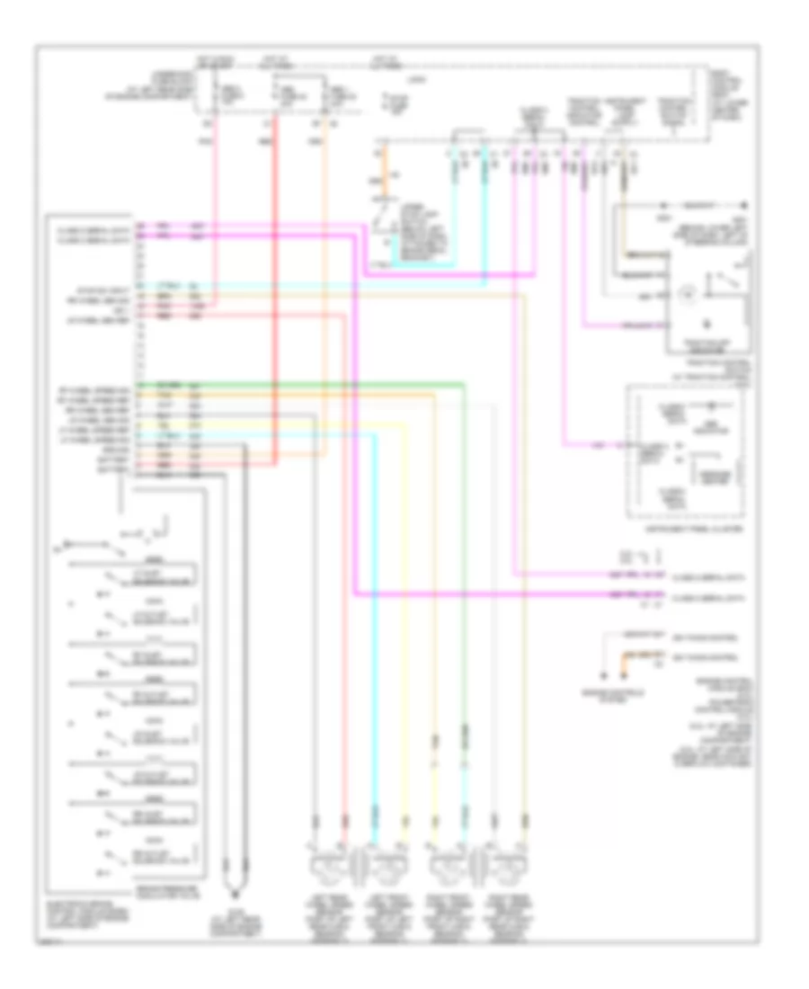
ANTI-LOCK BRAKES Anti-lock Brakes Wiring Diagram for Saturn Ion Red Line 2005 List of elements for Anti-lock Brakes Wiring Diagram for Saturn Ion Red Line 2005: 56 (2.0l: at left side of engine, near coolant overflow container) (2.2l: at left side of engine compartment) 2.2l 2.0l Abs 1 fuse 22 20a Abs 2 fuse 8 10a Abs fuse 40 40a Abs indicator Battery Body control module (bcm) (at lower center of dash) Brake pressure modulator valve Class 2 serial data Electronic brake control module (ecbm) (at left side of engine compartment) Engine control module (ecm) (2.2l) powertrain control module (2.0l) Engine controls system G109 (at left rear side of engine compartment) G201 (behind lower left side of dash, left of steering column) Ground Hot at all times Hot in run or start Ign 1 Ign timing control Instrument panel cluster Left front wheel speed sensor (part of left front hub & bearing assembly) Left rear wheel speed sensor (part of left rear hub & bearing assembly) Lf inlet solenoid valve Lf outlet solenoid valve Lf wheel speed ref Lf wheel speed sig Logic Lr inlet solenoid valve Lr outlet solenoid valve Lr wheel sen ref Lr wheel sen sig Message center Pnk Red Rf inlet solenoid valve Rf outlet solenoid valve Rf wheel speed ref Rf wheel speed sig Right front wheel speed sensor (part of right front hub & bearing assembly) Right rear wheel speed sensor (part of right rear hub & bearing assembly) Rr inlet solenoid valve Rr outlet solenoid valve Rr wheel sen ref Rr wheel sen sig S221 Stop fuse 15a Stop sw input Tan Traction control indicator control Traction control switch (w/ traction control) (2.2l) Traction control switch signal Traction off indicator Underhood fuse block (at left rear side of engine compartment) Upper stop lamp switch (below left side of dash, attached to brake pedal bracket)
ANTI-THEFT Anti-theft Wiring Diagram for Saturn Ion Red Line 2005 List of elements for Anti-theft Wiring Diagram for Saturn Ion Red Line 2005: 53 (2.0l: at rear of engine, near coolant overflow container) (2.2l: at left side of engine compt) (2.0l) powertrain control module (pcm) (2.2l) engine control module (ecm) (in body harness, 7.5 cm from rear compartment light breakout) s413 (near driver seat belt) (near front left passenger seat belt) 2.0l 2.2l 5v ref Acc Ajar switch B(+) Bcm (pwr) fuse 15a Bcm class 2 serial data Bcm elect fuse 20a Body control module (bcm) (at lower center of dash) C2 c2 Cluster fuse 7.5a Dash fuse 7.5a Driver door jamb switch (left front of dash, on outer trim cover) Driver door jamb switch signal Ecm class 2 serial data Engine controls system Exterior lights system Front passenger door jamb switch (right front of dash, on outer trim cover) Fuel injector control G201 (behind lower left side of dash, left of steering column) G301 (under driver's seat) G403 (under center of rear shelf) Gnd Horn relay ctrl Horns system Hot at all times Ignition switch Instrument panel cluster Interior lights system Left rear door jamb switch (sedan) Lock Logic Nca Off Off/ run/ crank volt Passenger door jamb switch signal Rear compartment lid latch (in rear compartment lid) Right rear door jamb switch (sedan) Run S221 S250 S351 S990 Security indicator Security indicator control Start Trunk ajar switch signal Turn/ hazard switch power
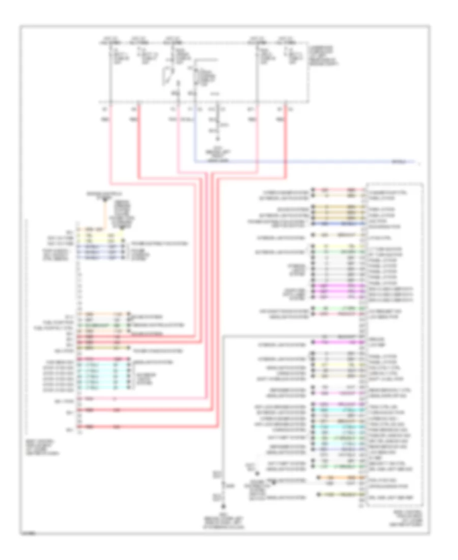
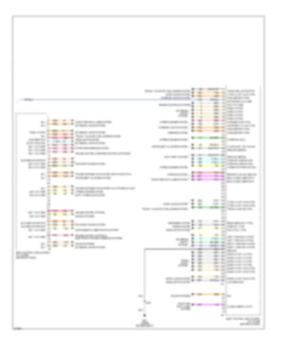
BODY CONTROL MODULES Body Control Modules Wiring Diagram (1 of 2) for Saturn Ion Red Line 2005 List of elements for Body Control Modules Wiring Diagram (1 of 2) for Saturn Ion Red Line 2005: 78 (sedan) mirrors system (coupe) power tops & mirrors systems 5v ref A/c request sig A10 Acc pwr Acc voltage Air conditioning system Anti-lock brakes system Anti-theft system B (+) B(+) B11 Bcm class 2 ser data Body control module (bcm) (at lower center of dash) Computer data lines system Defogger system Drl amb light sen ref Drl amb light sen sig Drv dr jamb sw sig Engine controls system Exterior lights system Fog lp rly ctrl Fog lp sw sig Fuel pump pwr Fuel pump rly ctrl G101 (behind left front headlamp) G201 (behind lower left side of dash, left of steering column) Ground Headlamps off sig Headlights system High beam sig Horn rly ctrl Horns system Hot at all times Ign 1 pwr Ign 3 pwr Interior lights system Ip batt 1 fuse 39 30a Ip batt 1a fuse 47 30a Ip batt 2 fuse 41 40a Low beam pwr Low beam sig Low ref Lp dim ctrl Lt turn sig pwr Off/run/crank pwr Panel lp pwr Park brake sw sig Park lp pwr Pass dr jamb sw sig Pnk Power distribution system Power distribution system (ignition switch) Power windows system Pwr window sw lockout ctrl (sedan) Rear defog rly ctrl Rear defog sw sig Red Rt turn sig pwr Run (ign 3) fuse 48 30a Run/ crank fuse 38 30a Run/ crank relay Run/crank pwr S101 S250 Security ind ctrl Shift interlock system Shift lk sol pwr Sound systems Stop lp sw sig Trac ctrl ind Trac ctrl sw sig Turn/haz sw pwr Underhood fuse block (at left rear side of engine compt) Warning system Washer pump ctrl Wiper sw sig 1 Wiper/washer system Body Control Modules Wiring Diagram (2 of 2) for Saturn Ion Red Line 2005 List of elements for Body Control Modules Wiring Diagram (2 of 2) for Saturn Ion Red Line 2005: 61 Acc voltage Air conditioning system Anti-theft system B(+) Bcm class 2 ser data Blower motor pwr Body control module (bcm) (at lower center of dash) Brake fluid lev sen sig Class 2 serial data Computer data lines system Courtesy lp low ctrl Cruise control & engine controls systems Cruise control system Cruise control system & electronic power steering systems Defogger system Door lk act lk ctrl Door lk act unlk ctrl Door locks system Engine controls system Exterior lights system Fog lp rly ctrl G301 (under driver's seat) Ground Ground (sedan) Headlights system High beam sig Horn rly ctrl Horns system Ign 1 voltage Ign 3 voltage Inadvertent pwr Instrument cluster system Interior lights system Left turn sig lp pwr Lf dr lk act unlk ctrl Lo coolant lev ind sig Low beam sig Mirrors system Park lp pwr Pass dr jamb sw sig Pnk Power distribution system (aux power outlet) Power distribution system (ignition switch) Rear defog rly ctrl Red Right turn sig lp pwr Run/crank voltage S351 Shift interlock system Sound systems Starting/charging system Stop lp sw sig Tan Trunk ajar ind ctrl Trunk rel motor pwr Trunk, tailgate, fuel doors system Warning system Washer pump ctrl Wiper mtr park sw sig Wiper sw sig 2 Wiper/washer system
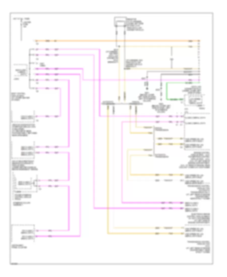
COMPUTER DATA LINES Computer Data Lines Wiring Diagram for Saturn Ion Red Line 2005 List of elements for Computer Data Lines Wiring Diagram for Saturn Ion Red Line 2005: 43 (i/p harness, 5cm from data link connector (dlc) breakout) s205 (not used) 2.0l 2.2l A11 A12 Automatic transmission B10 Bcm class 2 serial data Body control module (bcm) (at lower center of dash) Class 2 serial data Data link connector (dlc) (under lower left side of dash) Ebcm class 2 serial data Electronic brake control module (ebcm) (w/ anti-lock brakes) (at left side of engine compartment) Engine control (2.2l) powertrain control (2.0l) (2.2l: at left side of engine compartment) (2.0l: at rear of engine, near coolant overflow container) Eps class 2 serial data G201 (behind lower left side of dash, left of steering column) G203 (behind lower left side of dash, left of steering column) High speed gm lan serial data bus + High speed gm lan serial data bus - Hot at all times Inflatable restraint sensing & diagnostic module (sdm) (under center console, behind emergency brake) Instrument panel cluster Ipc class 2 serial data Lighter fuse 15a Logic Low speed gm lan serial data Manual transmission Module (ecm) Module (pcm) Power steering control module (pscm) Radio Resistor (in i/p harness, lower left side of dash, 6 cm from data link connector (dlc)) S215 (i/p harness, 6cm from data link connector (dlc) breakout) S221 S233 Sdm class 2 serial data Steering column assembly Tan Transmission control module (tcm) (2.2l) (at left rear of engine compartment, near strut tower) Transmission control module (tcm) (automatic transmission only) (at left rear of engine compartment, near strut tower) Vcim class 2 serial data Vehicle communication interface module (vcim) (if equipped) (at center of rear package shelf, between rear speakers)
COOLING FAN
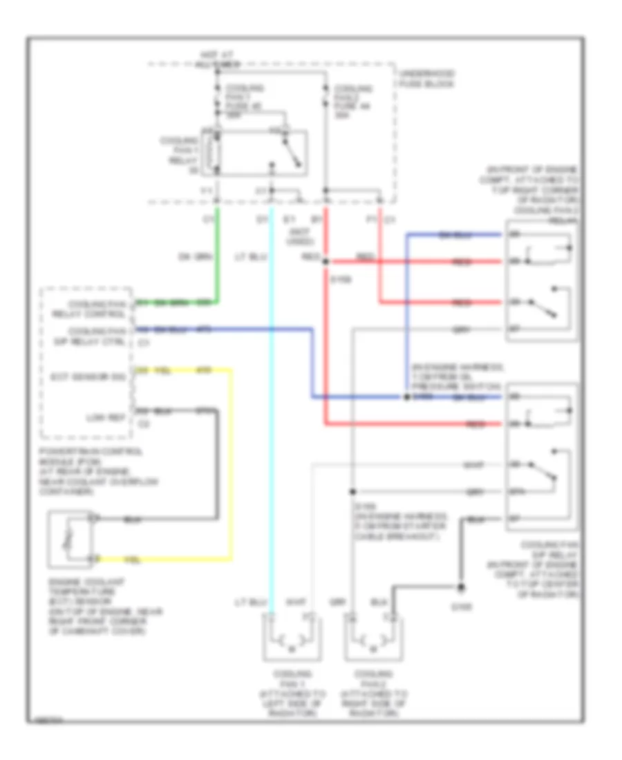
2.0L VIN P 2.0L VIN P, Cooling Fan Wiring Diagram for Saturn Ion Red Line 2005 List of elements for 2.0L VIN P, Cooling Fan Wiring Diagram for Saturn Ion Red Line 2005: 23 (in engine harness, 1 cm from oil pressure switch) s160 (in front of engine compt, attached to top right corner of radiator) cooling fan 2 relay (not used) 87a Cooling fan 1 (attached to left side of radiator) Cooling fan 1 fuse 45 30a Cooling fan 1 relay Cooling fan 2 (attached to right side of radiator) Cooling fan 2 fuse 44 30a Cooling fan relay control Cooling fan s/p relay (in front of engine compt, attached to top center of radiator) Cooling fan s/p relay ctrl Ect sensor sig Engine coolant temperature (ect) sensor (on top of engine, near right front corner of camshaft cover) F1 c1 G105 Hot at all times Low ref Powertrain control module (pcm) (at rear of engine, near coolant overflow container) Red S156 (in engine harness, 5 cm from starter cable breakout) S158 Underhood fuse block
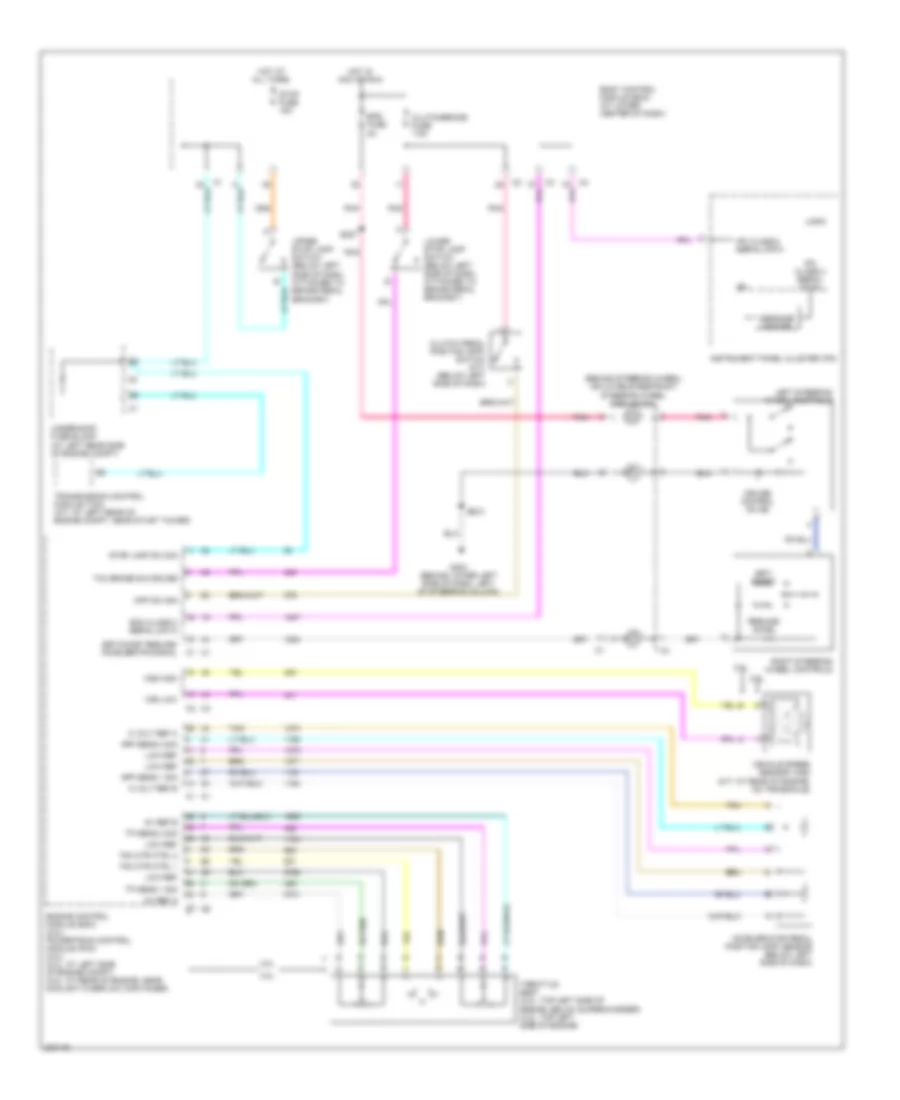
CRUISE CONTROL Cruise Control Wiring Diagram for Saturn Ion Red Line 2005 List of elements for Cruise Control Wiring Diagram for Saturn Ion Red Line 2005: 53 (behind steering wheel) inflatable restraint steering wheel module coil 2.0l 2.0l 2.2l 2.2l 5 volt ref a 5 volt ref b 5v ref a 5v ref b Accelerator pedal position (app) sensor (below left side of dash) All times App sens 1 sig App sens 2 sig Body control module (bcm) (at lower center of dash) Clutch pedal position (cpp) switch (m/t) (below left side of dash) Clutch/brake fuse 7.5a Cpp sw sig Cruise control on ind Ecm class 2 serial data Engine control module (ecm) (2.2l) powertrain control module (pcm) (2.0l) (2.2l: at left side of engine compt) (2.0l: at rear of engine, near coolant overflow container) Eps fuse 2a G203 (behind lower left side of dash, left of steering column) Hot at Hot in acc or run Instrument panel cluster (ipc) Ipc class 2 serial data Left steering wheel controls Logic Low ref Lower stop lamp switch (below left side of dash, attached to brake pedal bracket) Message center Pnk Resume/ accel Right steering wheel controls S227 S233 Set/ coast Set/coast resume/ accelerate signal Stop fuse 15a Stop lamp sw sig Tac mtr ctrl 1 Tac mtr ctrl 2 Tan Tcc brake sw/cruise Throttle body (2.0l: top left side of engine, below supercharger) (2.2l: top left side of engine) Tp sens 1 sig Tp sens 2 sig Transmission control module (tcm) (a/t: at left rear of engine compt, near sturt tower) Underhood fuse block (at left rear side of engine compt) Upper stop lamp switch (below left side of dash, attached to brake pedal bracket) Vehicle speed sensor (vss) (m/t: at rear of engine, on transaxle) Vss high Vss low
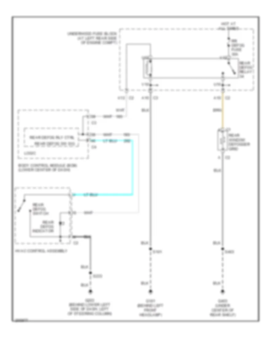
DEFOGGERS Defoggers Wiring Diagram for Saturn Ion Red Line 2005 List of elements for Defoggers Wiring Diagram for Saturn Ion Red Line 2005: 26 Body control module (bcm) (lower center of dash) C2 a C2 a10 C2 a12 C3 a10 G101 (behind left front headlamp) G203 (behind lower left side of dash, left of steering column) G403 (under center of rear shelf) Hot at all times Hvac control assembly Logic Rear defog indicator Rear defog relay Rear defog rly ctrl Rear defog sw sig Rear defog switch Rear window defogger grid Rr defog fuse 30a S101 S233 S403 U10 U12 Underhood fuse block (at left rear side of engine compt) V10 V12
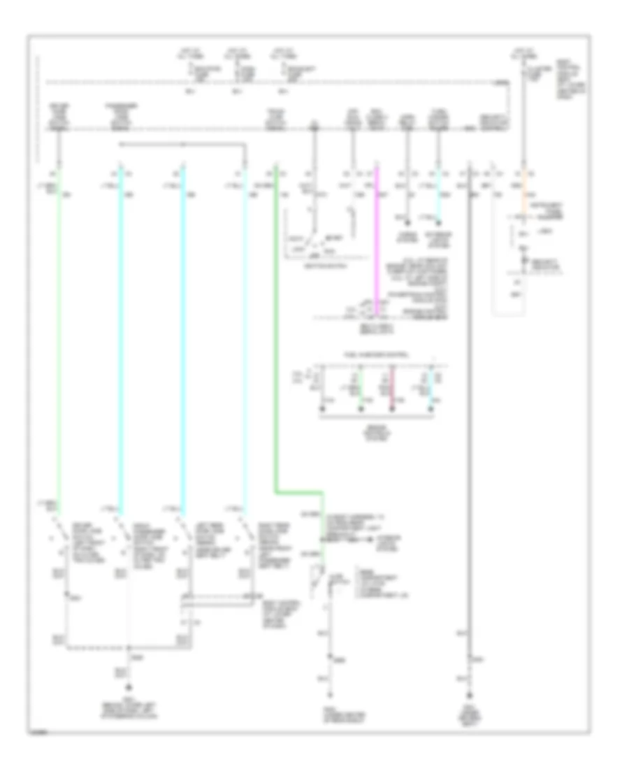
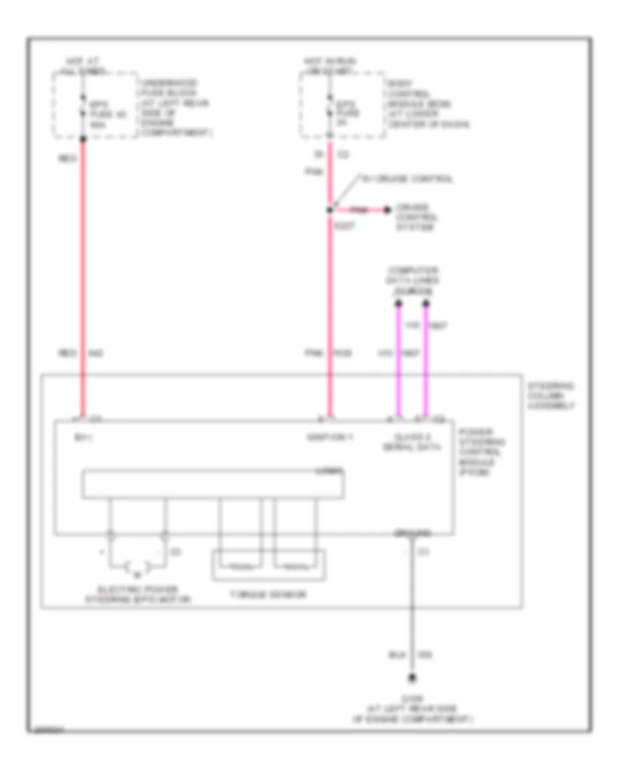
ELECTRONIC POWER STEERING Electronic Power Steering Wiring Diagram for Saturn Ion Red Line 2005 List of elements for Electronic Power Steering Wiring Diagram for Saturn Ion Red Line 2005: 23 - c3 B(+) Body control module (bcm) (at lower center of dash) Class 2 serial data Computer data lines system Cruise control system Electric power steering (eps) motor Eps fuse 2a Eps fuse 43 60a G109 (at left rear side of engine compartment) Ground Hot at all times Hot in run or start Ignition 1 Logic Pnk Power steering control module (pscm) Red S227 Steering column assembly Torque sensor Underhood fuse block (at left rear side of engine compartment) W/ cruise control
ENGINE PERFORMANCE
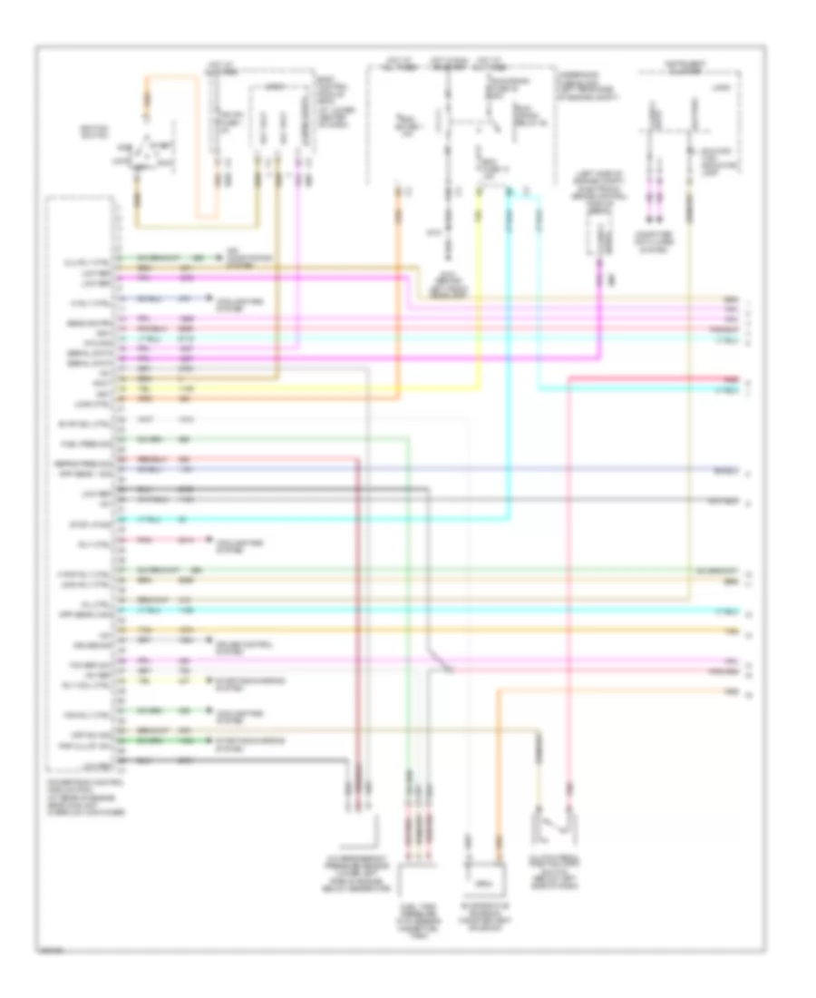
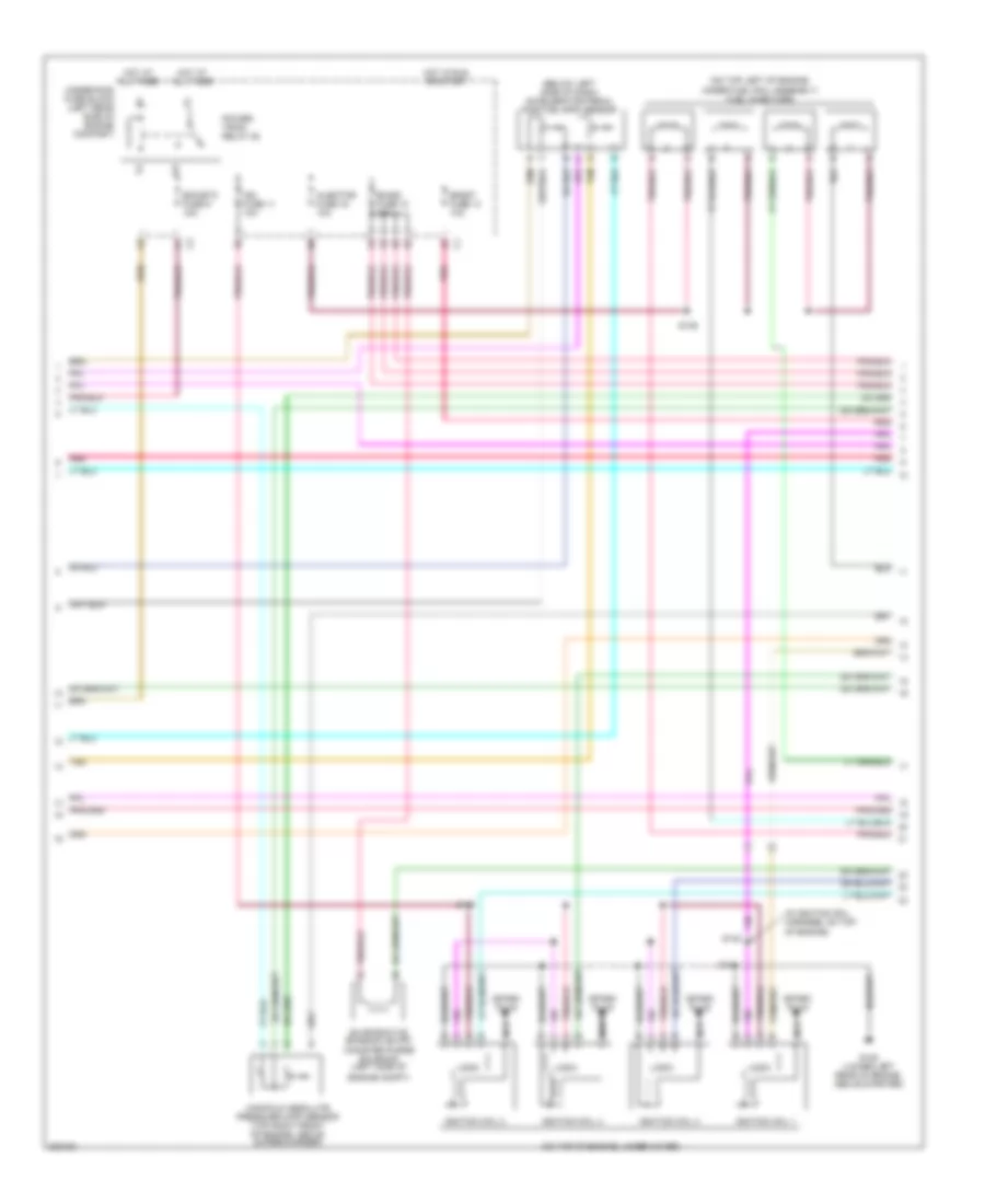
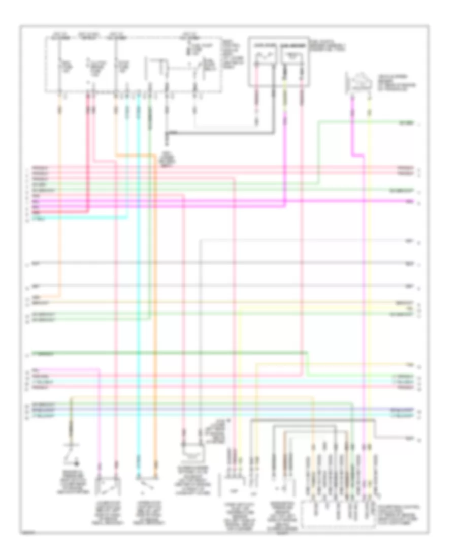
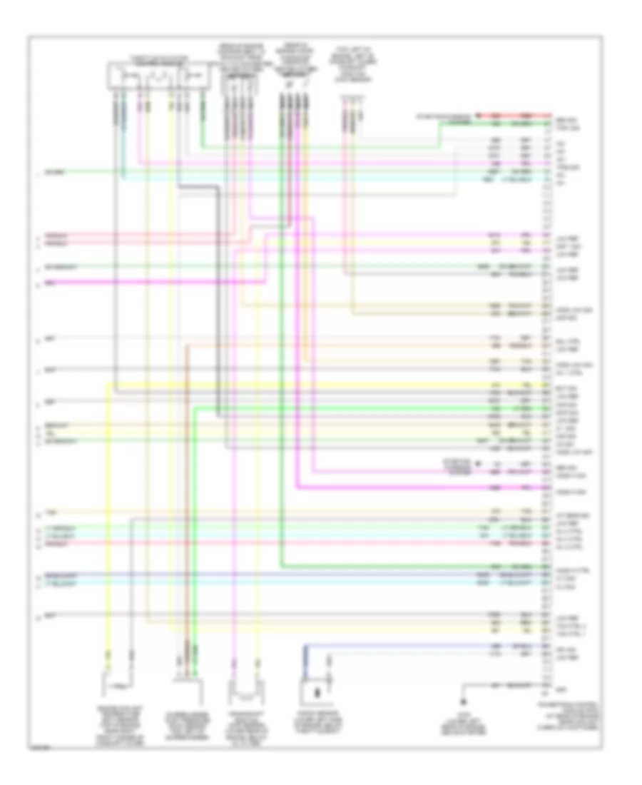
2.0L VIN P 2.0L VIN P, Engine Performance Wiring Diagram (1 of 4) for Saturn Ion Red Line 2005 List of elements for 2.0L VIN P, Engine Performance Wiring Diagram (1 of 4) for Saturn Ion Red Line 2005: 67 (at lower center of dash) (left side of engine compt) electronic brake control module (ebcm) +5v +5v ref A/c refrigerant pressure sensor (lower left side of engine, below generator) A10 Acc Acc volt Accy Air conditioning system App sens 1 sig App sens 2 sig Battery Body control module (bcm) Class 2 data Clu rly ctrl Clutch pedal position (cpp) switch (below left side of dash) Computer data lines system Cooling fans system Cpp sw sig Cruise control system Cruise sig Data class 2 Ecm fuse 1 10a Ecm fuse 13 10a Evap sol ctrl Evaporative emission canister vent solenoid F pmp rly ctrl Fan rly ctrl Fuel pres sig Fuel tank pressure (ftp) sensor (inside fuel tank) G101 (behind left front headlamp) Hi rly ctrl Hot at all times Hot in run or start Iat2 sig Ign sw fuse 1 2a Ign1 Ignition switch Instrument cluster Load ctrl Lock Logic Low ref Main rly ctrl Malfunc- tion indicator lamp Mil ctrl Off Pnk Pnp clu st sw Powertrain control module (pcm) (at rear of engine, near coolant overflow container) Red/pnk Refrig pres sig Rly coil ctrl Rly ctrl Run Run/ crank relay 28 Run/crank fuse 38 30a k1 S101 Sens sig pri Serial data Start Starting/charging system Stop lp sig Tan Tcc brk sw Underhood fuse block (left rear side of engine compt) 2.0L VIN P, Engine Performance Wiring Diagram (2 of 4) for Saturn Ion Red Line 2005 List of elements for 2.0L VIN P, Engine Performance Wiring Diagram (2 of 4) for Saturn Ion Red Line 2005: 30 (below left side of dash) accelerator pedal position (app) sensor (in ignition coil harness, on top of engine) (on top left of engine, under fuel rail assembly) fuel injectors (on top of engine, under cover) Boost fuse 14 10a Ecm/etc fuse 9 15a Emiss fuse 10 15a Engine compt) Evaporative emission (evap) canister purge solenoid (left side of G105 (lower left rear of engine, above starter) Hot at all times Hot in run or start Ign fuse 11 10a Ignition coil 1 Ignition coil 2 Ignition coil 3 Ignition coil 4 Injector fuse 16 10a Logic Manifold absolute pressure (map) sensor (top right front of engine, above supercharger) Nca Pnk Power- train relay 28 S139 S140 S141 S142 Spark plug Tan Underhood fuse block (left rear side of engine compart) 2.0L VIN P, Engine Performance Wiring Diagram (3 of 4) for Saturn Ion Red Line 2005 List of elements for 2.0L VIN P, Engine Performance Wiring Diagram (3 of 4) for Saturn Ion Red Line 2005: 44 (pins 1-14 not used) (pins 16-21 not used) (pins 23-30 not used) (pins 32-35 not used) (pins 38-43 not used) (pins 46-56 not used) +5v Ba1 Ba2 Ba3 Ba4 Baro sig Barometric pressure sensor (on top left side of engine, behind supercharger inlet) Bcm fuse 15a Body control module (bcm) (at lower center of dash) Clutch/ brake fuse 7.5a Engine oil pressure (eop) switch (lower rear of engine, above starter) Evap sol Fuel pump Fuel pump & sender assembly (inside fuel tank) Fuel pump fuse 15a Fuel pump relay Fuel sender G105 (lower left rear of engine, above starter) G301 (under driver's seat) Hot at all times Hot in acc or run Iat Low ref Lower stop lamp switch (below left side of dash, on brake pedal bracket) Maf Mass air flow/ inlet air temperature sensor (on left side of engine, above air cleaner) Nca Pnk Powertrain control module (pcm) (at rear of engine near coolant over- flow container) S351 Stop fuse 15a Supercharger bypass valve solenoid (on top front center of engine, in front of camshaft cover) Sw sig Tan Upper stop lamp switch (below left side of dash, on brake pedal bracket) Vehicle speed sensor (at rear of engine, on transaxle) Vss hi Vss low 2.0L VIN P, Engine Performance Wiring Diagram (4 of 4) for Saturn Ion Red Line 2005 List of elements for 2.0L VIN P, Engine Performance Wiring Diagram (4 of 4) for Saturn Ion Red Line 2005: 44 (rear of engine compartment, in exhaust near catalytic converter) heated oxygen sensor 2 (rear of engine compt, in exhaust manifold) heated oxygen sensor 1 (top left of engine, left of camshaft cover) camshaft position (cmp) sensor +5v A tan Ckp 1 sig Cmp sig Crankshaft position (ckp) sensor (lower rear of engine, below oil filter) Ect sig Engine coolant temperature (ect) sensor (top of engine, near right front corner of camshaft cover) G105 (lower left rear of engine, above starter) Gen sig Gnd Ho2s hi ctrl Ho2s hi sig Ho2s low sig Iat sens sig Ic 1 sig Ic 2 sig Ic 3 sig Ic4 sig Inj 1 ctrl Inj 2 ctrl Inj 3 ctrl Inj 4 ctrl Knock sensor (lower left side of engine, below throttle body) Ks1 sig Low ref Maf sig Map sig Nca Powertrain control module (pcm) (at rear of engine near coolant overflow container) Red Scip sig Sol ctrl Starting/ charging system Starting/charging system Supercharger inlet pressure (scip) sensor (top left of supercharger) Tac ctrl 1 Tac ctrl 2 Tan Throttle actuator control module Tps1 sig Tps2 sig
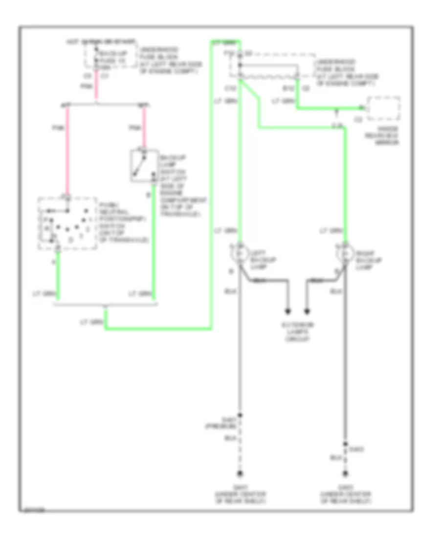
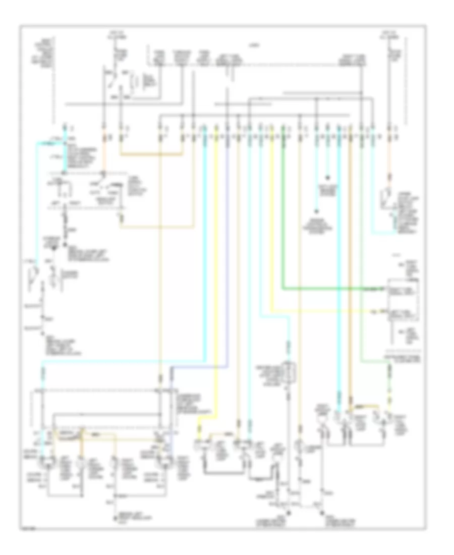
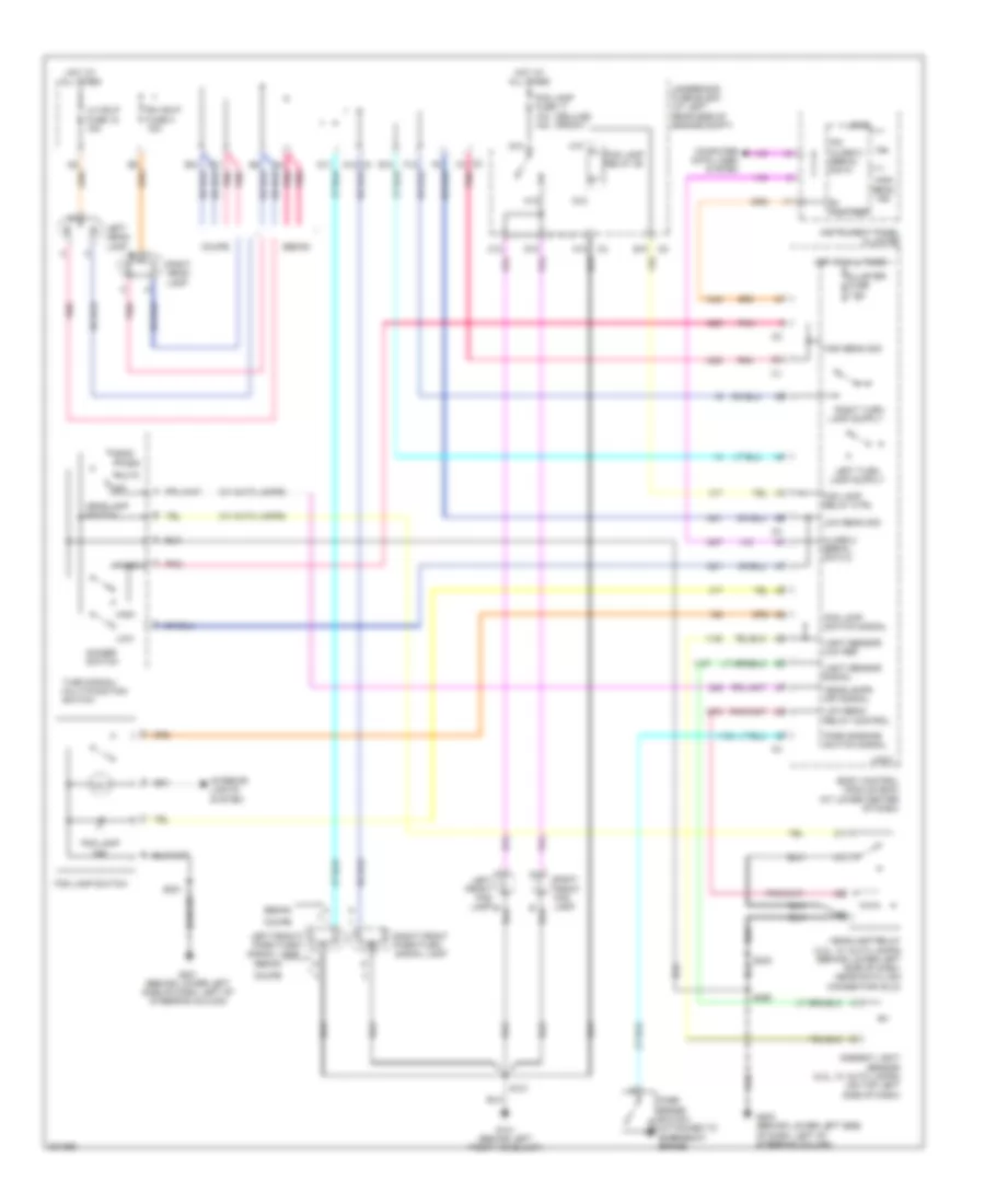
EXTERIOR LIGHTS Back-up Lamps Wiring Diagram for Saturn Ion Red Line 2005 List of elements for Back-up Lamps Wiring Diagram for Saturn Ion Red Line 2005: 20 2.2l A/t Back-up fuse 15 10a Backup lamp switch (at left side of engine compartment, on top of transaxle) C12 C2 b12 Exterior lamps circuit F11 G401 (under center of rear shelf) G403 (under center of rear shelf) Hot in run or start Inside rearview mirror Left backup lamp M/t Park/ neutral position(pnp) switch (on top of transaxle) Pnk Right backup lamp S401 (premium) S403 Underhood fuse block (at left rear side of engine compt) Exterior Lamps Wiring Diagram for Saturn Ion Red Line 2005 List of elements for Exterior Lamps Wiring Diagram for Saturn Ion Red Line 2005: 67 (behind left front headlamp) g101 (coupe) (coupe) (sedan) b (sedan) (sedan) a (sedan) g Alc/ park relay Anti-lock brakes system Auto B2 c2 Bb1 Bb2 Bb3 Bb4 Body control module (bcm) (at lower center of dash) C2 f12 C3 a12 Center high mounted stop lamp (chmsl) (6 bulbs) D11 D2 (not used) E12 Engine controls/ transmissions system G201 (behind lower left side of dash, left of steering column) G203 (behind lower left side of dash, left of steering column) G401 (under center of rear shelf) G403 (under center of rear shelf) Hazard switch Head Headlamp switch Hot at all times Instrument panel cluster (ipc) Interior lights system Left Left backup lamp Left front marker lamp (coupe) Left front park/ turn signal lamp Left tail/ stop lamp Left tail/ turn signal lamp Left turn signal ind Left turn signal input License lamp Logic Off Park Park fuse 15a Park lamp relay ctrl Right Right backup lamp Right front marker lamp (coupe) Right front park/ turn signal lamp Right tail/ stop lamp Right tail/ turn signal lamp Right turn signal ind Right turn signal input S101 S221 S260 S270 (in i/p harness, 5.5 cm from body control module (bcm) breakout) S375 S401 (premium) S403 S990 Stop fuse 15a Turn signal/ multi- function switch Turn switch Underhood fuse block (at left rear side of engine compt) Upper stop lamp switch (below left side of dash, attached to brake pedal bracket)
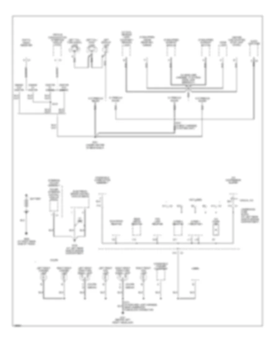
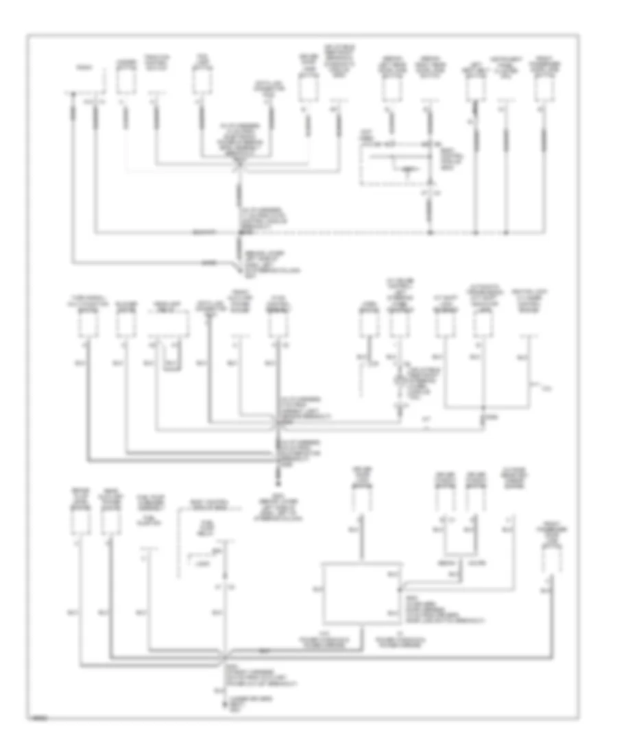
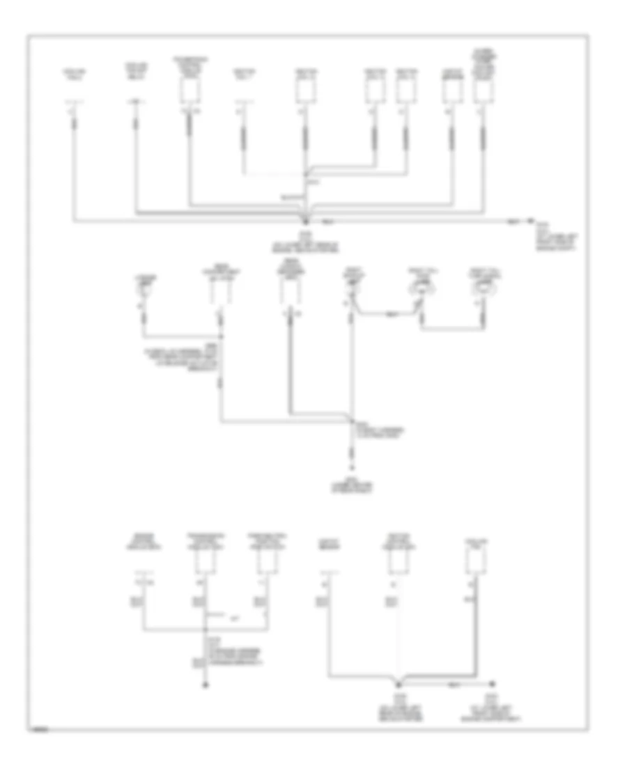
GROUND DISTRIBUTION Ground Distribution Wiring Diagram (1 of 3) for Saturn Ion Red Line 2005 List of elements for Ground Distribution Wiring Diagram (1 of 3) for Saturn Ion Red Line 2005: 63 (coupe) (if equipped) inside rearview mirror (if equipped) sunroof module (if equipped) sunroof switch (in headliner harness, 10 cm from dome lamp breakout) s375 (not used) (sedan) (under center of rear shelf) (w/ dual reading lamp) courtesy/ reading lamp A/c compressor clutch A/c diode A10 A11 Audio amplifier Battery Center high mounted stop lamp (chmsl) Coupe D11 Digital radio receiver Dome lamp E17 Electronic brake control module (ebcm) F10 Fog lamp relay 26 G101 (behind left front headlamp) G109 (at left rear side of engine compartment) G12 G401 G502 (at right rear side of trunk) Horn L10 L11 Left backup lamp Left front fog lamp Left front marker lamp Left front park/turn signal lamp Left tail/ stop lamp Left tail/ turn signal lamp Manual a/c Onstar w/ s-band Onstar w/o s-band Power steering control module (pscm) Q11 Rear defog relay 34 Right front fog lamp Right front marker lamp Right front park/turn signal lamp Run/crank relay 28 S-band w/ onstar S-band w/o onstar S401 (in body harness, 13 cm from g401) S415 Steering column assembly Underhood fuse block (at left rear side of engine compartment) V10 Vehicle communication interface module (vcim) W/ abs W/ premium sound W/o premium sound Windshield washer fluid pump Windshield wiper motor assembly Wiper 1 relay 32 Wiper 2 relay 32 Ground Distribution Wiring Diagram (2 of 3) for Saturn Ion Red Line 2005 List of elements for Ground Distribution Wiring Diagram (2 of 3) for Saturn Ion Red Line 2005: 56 (behind lower left side of dash, left of steering column) g201 (in i/p harness, 10 cm from electronic power steering (eps) assembly breakout) s221 (in i/p harness, 5 cm from ambient light sensor breakout) s233 (not used) (sedan) (under driver's seat) g301 (w/ cruise control) left steering wheel controls 2.2l A/t A/t shift lock solenoid A12 Automatic transmission (a/t) shift indicator lamp Ba4 Bare Blower motor Body control module (bcm) Brake fluid level switch Coupe Data link connector (dlc) Driver door Driver door lock switch Driver window switch Fog lamp switch Front auxiliary power outlet Front passenger door jamb switch Front passenger door lock switch Fuel pump & sender assembly Fuel pump (fp) Fuel pump relay G203 (behind lower left side of dash, left of steering column) Hazard switch Headlamp relay Horn switch Hvac control assembly Ignition lock cylinder control switch Inflatable restraint sensing & diagnostic module (sdm) Inflatable restraint steering wheel module coil Instrument panel cluster (ipc) Jamb Left rear door jamb switch Left seat belt switch Logic Nca Outside rearview mirror switch Radio Rear auxiliary power outlet Right rear door jamb switch S351 (in body harness, 38.5 cm from auxiliary power outlet breakout) S355 S533 (in driver's door harness, 3.5 cm from driver's door lock switch breakout) Sedan Switch Traction control switch Turn signal/ multi-function switch W/ power windows & power mirrors W/o power windows & power mirrors Ground Distribution Wiring Diagram (3 of 3) for Saturn Ion Red Line 2005 List of elements for Ground Distribution Wiring Diagram (3 of 3) for Saturn Ion Red Line 2005: 29 A/t Cooling fan Cooling fan 2 Cooling fan s/p relay Engine control module (ecm) G103 (2.0l) (at lower left front side of engine compt) G103 (2.2l) (at lower left front side of engine compartment) G105 (2.0l) (on lower left rear of engine, above starter) G105 (2.2l) (on lower left rear of engine, above starter) G403 (under center of rear shelf) Ignition coil 1 Ignition coil 2 Ignition coil 3 Ignition coil 4 Ignition control module (icm) License lamp Maf/iat sensor Park/neutral position (pnp) switch Powertrain control module (pcm) Rear compartment lid latch Rear window defogger grid Right backup lamp Right tail/ stop lamp Right tail/ turn signal lamp S141 S403 (in body harness, 13 cm from g403) S990 (in deck lid harness, 10 cm from rear compartment lid release actuator breakout) Super- charger inter- cooler coolant pump Transmission control module (tcm)
HEADLIGHTS Headlights Wiring Diagram for Saturn Ion Red Line 2005 List of elements for Headlights Wiring Diagram for Saturn Ion Red Line 2005: 73 (deluxe) (front) (w/ auto lamps) A10 Ambient light sensor (2.2l, w/ auto lamps) (on top left side of dash) Auto B+ voltage B10 Body control module (bcm) (at lower center of dash) C11 C12 C2 f4 C3 a12 Class 2 serial data 2 Cluster fuse 7.5a Computer data lines system Coupe D11 D12 Dimmer switch E10 E12 F12 Flash Fog lamp fuse 17 10a 15a Fog lamp ind Fog lamp relay 26 Fog lamp relay ctrl Fog lamp switch Fog lamp switch signal G10 G101 (behind left front headlamp) G12 G201 (behind lower left side of dash, left of steering column) G203 (behind lower left side of dash, left of steering column) H10 H12 Head Headlamp relay (2.2l, w/ auto lamps) (behind lower left side of dash, near data link connector (dlc)) Headlamp switch Headlamps off signal High High beam ind High beam sig Hot at all times Instrument panel cluster Interior lights system Ipc class 2 serial data Left front fog lamp b Left front park/turn signal lamp Left head- lamp Lh hdlp fuse 18 15a Light sensor low ref Light sensor signal Logic Low Low beam relay control Low beam sig Off Park Park barake switch signal Park brake switch (attached to emergency brake) Pnk Rh hdlp fuse 4 15a Right front fog lamp Right front park/turn signal lamp Right head- lamp S101 S221 S233 S260 Sedan Turn signal/ multi-function switch Underhood fuse block (at left rear side of engine compt)
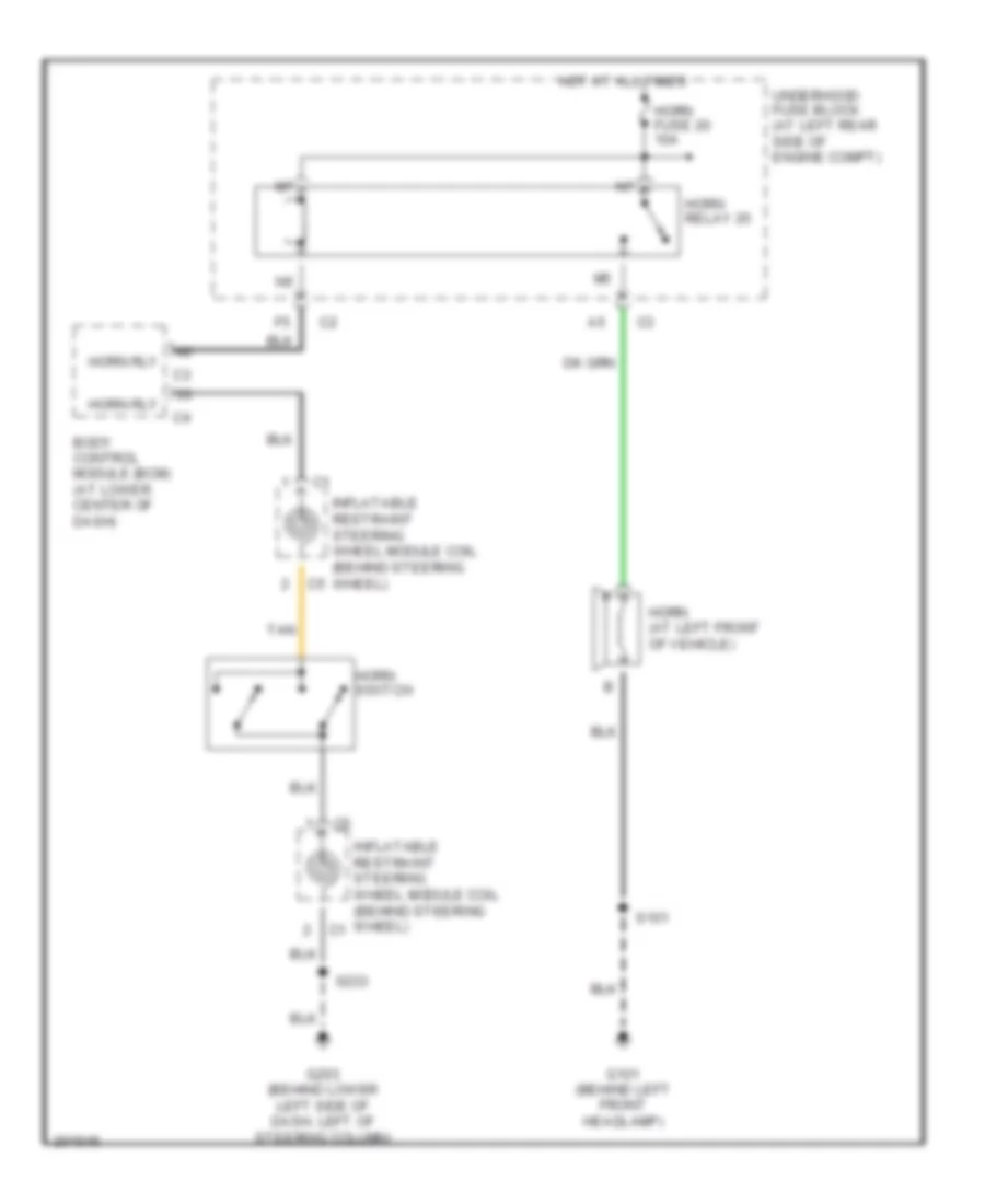
HORN Horn Wiring Diagram for Saturn Ion Red Line 2005 List of elements for Horn Wiring Diagram for Saturn Ion Red Line 2005: 14 Body control module (bcm) (at lower center of dash) G101 (behind left front headlamp) G203 (behind lower left side of dash, left of steering column) Horn (at left front of vehicle) Horn fuse 20 10a Horn relay 25 Horn rly Horn switch Hot at all times Inflatable restraint steering wheel module coil (behind steering wheel) S101 S233 Tan Underhood fuse block (at left rear side of engine compt)
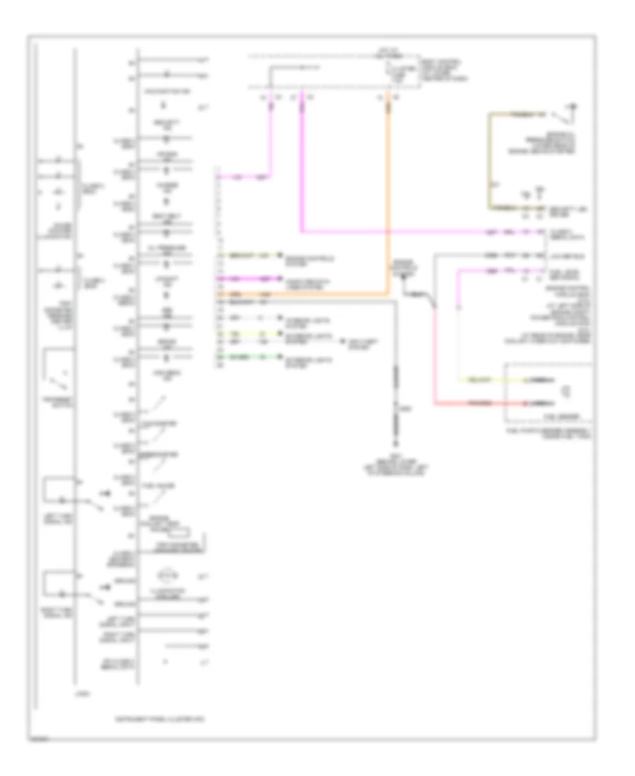
INSTRUMENT CLUSTER Instrument Cluster Wiring Diagram for Saturn Ion Red Line 2005 List of elements for Instrument Cluster Wiring Diagram for Saturn Ion Red Line 2005: 53 2.0l 2.2l Abs ind Air bag ind Anti-theft system Body control module (bcm) (at lower center of dash) Brake ind Charge ind Class 2 (bcm) Class 2 (bcm/ecm/ eps/ebcm) Class 2 (ebcm) Class 2 (ecm) Class 2 (sdm) Class 2 serial data Cluster fuse 7.5a Computer data lines system Engine control module (ecm) (2.2l) (at left side of engine compt) powertrain control module (pcm) (2.0l) (at rear of engine, near coolant overflow container) Engine controls system Engine coolant temp gauge Engine oil pressure switch (lower rear of engine, above starter) Exterior lights system Fuel gauge Fuel level sen signal Fuel pump & sender assembly (inside fuel tank) Fuel sender G201 (behind lower left side of dash, left of steering column) Gauge pointer illumination Ground High beam ind Hot at all times Illumination (6 bulbs) Instrument panel cluster (ipc) Interior lights system Ipc class 2 serial data Left turn signal ind Left turn signal input Logic Low ref bus Malfunction ind Nca Oil pressure ind Right turn signal ind Right turn signal input S250 Seat belt ind Security ind Security led driver Speedometer Tachometer Trip odometer/ message center Trip/ odometer message center illum Trip/reset switch Up-shift ind
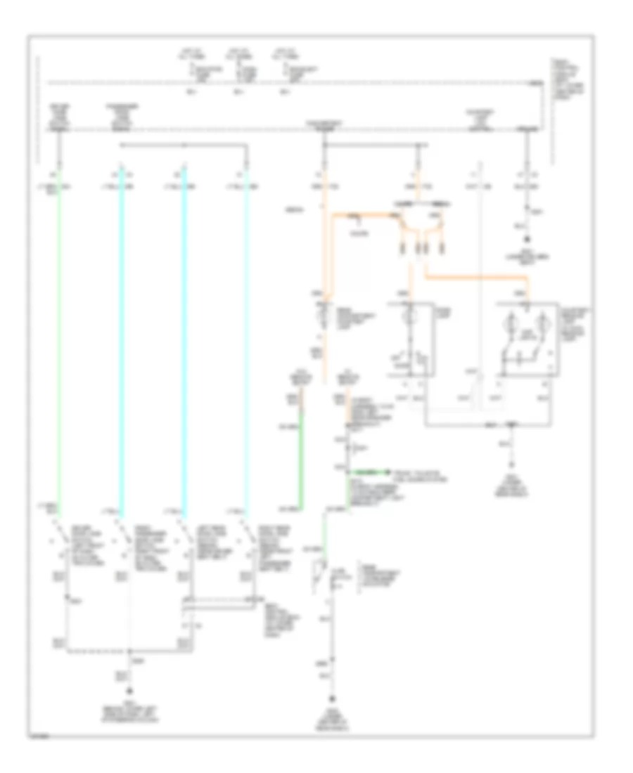
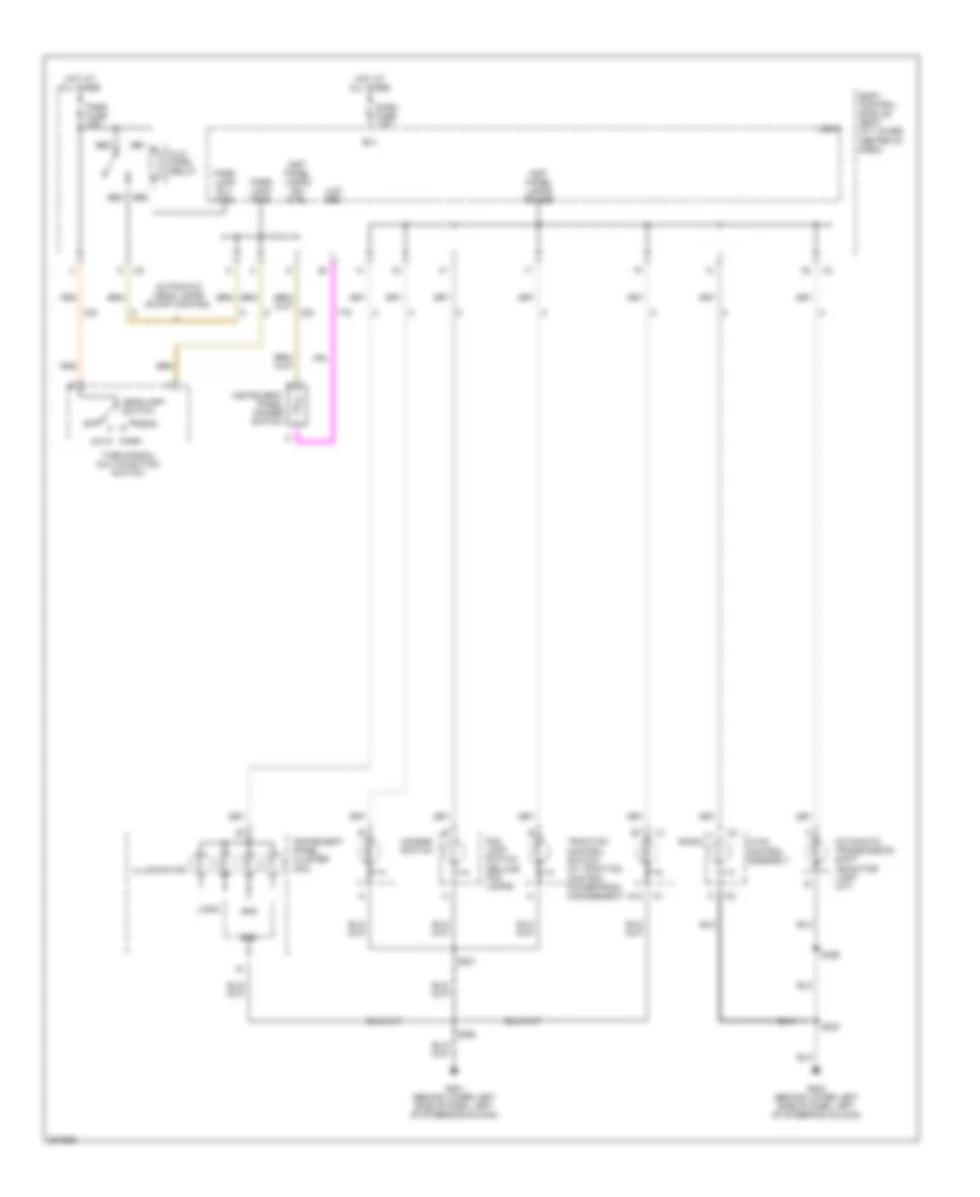
INTERIOR LIGHTS Courtesy Lamps Wiring Diagram for Saturn Ion Red Line 2005 List of elements for Courtesy Lamps Wiring Diagram for Saturn Ion Red Line 2005: 42 (in body harness, 7.5 cm from left rear speaker breakout) s411 Ajar switch B(+) Bcm (pwr) fuse 15a Bcm elect fuse 20a Body control module (bcm) (at lower center of dash) Coupe Courtesy lamp low control Courtesy/ reading lamp (w/ dual reading lamp) D401 Dash fuse 7.5a Dome lamp Door Driver door jamb switch (left front of dash, on outer trim cover) Driver door jamb switch signal Front passenger door jamb switch (right front of dash, on outer trim cover) G201 (behind lower left side of dash, left of steering column) G301 (under driver's seat) G401 (under center of rear shelf) G403 (under center of rear shelf) Ground Hot at all times Inadvertent power Left rear door jamb switch (sedan) (near driver seat belt) Logic Map lights Nca Off Passenger door jamb switch signal Rear compartment courtesy lamp Rear compartment lid release actuator Right rear door jamb switch (sedan) (near front left passenger seat belt) S221 S250 S351 S375 S413 (in body harness, 7.5 cm from rear compartment light breakout) S990 Sedan Trunk, tailgate, fuel doors system W/ remote entry W/o remote entry Instrument Illumination Wiring Diagram for Saturn Ion Red Line 2005 List of elements for Instrument Illumination Wiring Diagram for Saturn Ion Red Line 2005: 40 A12 Alc/ park relay Auto Automatic head lamps on-off control Automatic transmission shift indicator lamp (a/t) B(+) Bb1 Bb2 Bb3 Bb4 Body control module (bcm) (at lower center of dash) Dash fuse 7.5a Fog lamp switch (deluxe fog lamps) G201 (behind lower left side of dash, left of steering column) G203 (behind lower left side of dash, left of steering column) Gnd Hazard switch Head Headlamp switch Hot at all times Hvac control assembly Illumination Inst panel lamps dim ctrl Inst panel lamps power Instrument panel cluster (ipc) Instrument panel dimmer switch Logic Low ref Off Park Park fuse 15a Park lamp pwr Park lamp rly ctrl Radio S221 S233 S250 S355 Traction control switch (w/ traction control powertrain management) Turn signal/ multifunction switch
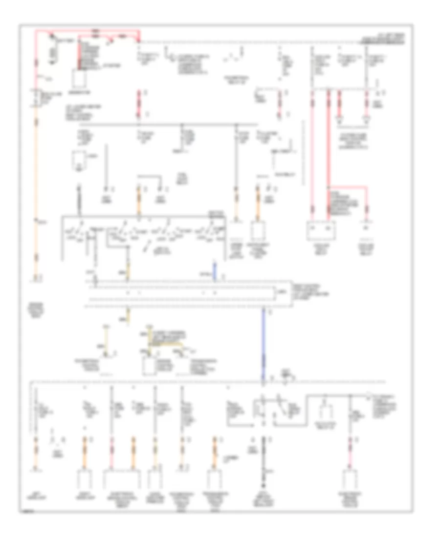
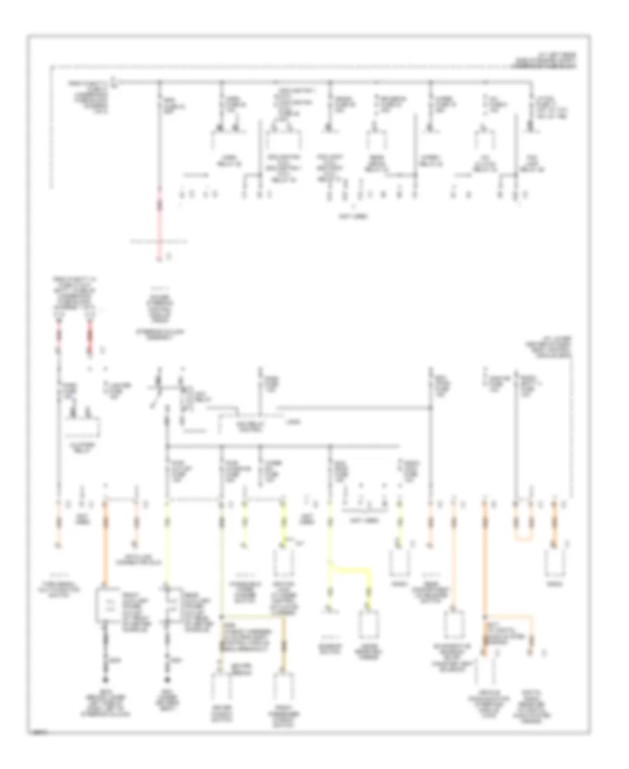
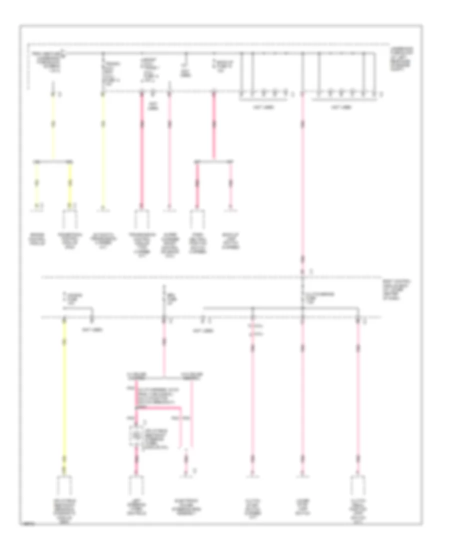
POWER DISTRIBUTION Power Distribution Wiring Diagram (1 of 3) for Saturn Ion Red Line 2005 List of elements for Power Distribution Wiring Diagram (1 of 3) for Saturn Ion Red Line 2005: 79 (at left rear side of engine compt) underhood fuse block (at lower center of dash) body control module (bcm) (not used) 2.0l 2.2l 4 speed a/t 5v ref A/c clutch relay 24 A/t A10 A11 Aa2 Aa3 Abs fuse 22 20a Abs fuse 40a Abs fuse 8 10a Acc Audio amplifier (premium) B1 c2 B11 c2 Ba2 Battery Bcm elect fuse 20a Body control module (bcm) (at lower center of dash) C1 engine control module Cluster fuse 7.5a Cooling fan 2 fuse 44 30a (2.0l) Cooling fan 2 relay Cooling fan s/p relay E4 c2 Ecm inline fuse 10a Electronic brake control module Electronic brake control module (ebcm) Engine control module (ecm) Fuel pump fuse 15a Fuel pump relay G101 (behind left front headlamp) Generator Ign sw fuse 2a Ignition switch Instrument panel cluster (ipc) Ip batt 1 fuse 39 30a Ip batt 1a fuse 47 30a Ip batt 2 fuse 41 40a Key-in switch Left headlamp Left rear side of engine compt) s104 Lh hdlp fuse 18 15a Lock Lock off Logic Off Pnk Powertrain control module Powertrain control module (pcm) (2.0l) Powertrain relay 29 Radio fuse 21 20a Red Rh hdlp fuse 4 15a Right headlamp Run Run (ign 3) fuse 30a Run relay Run/ crank fuse 38 30a Run/ crank relay S101 S150 (in engine harness, 5 cm from engine harness breakout) red S158 (in engine harness, 6 cm from starter solenoid breakout) red S310 Start Starter Stop fuse 15a Tcm (2.2l) ecm (2.0l) fuse 1 10a To eps1 fuse 43, eps fuse 43 (underhood fuse block) (diagram 2 of 3) To park fuse (body control module) (diagram 2 of 3) To trans 2 fuse 13 (underhood fuse block) (diagram 3 of 3) Transmission control module (tcm) (2.2l) Transmission control module (tcm) (4 speed) Upper stop lamp switch Power Distribution Wiring Diagram (2 of 3) for Saturn Ion Red Line 2005 List of elements for Power Distribution Wiring Diagram (2 of 3) for Saturn Ion Red Line 2005: 75 (at left rear side of engine compt) underhood fuse block (at lower center of dash) body control module (bcm) (coupe) (not used) (sedan) c1 (w/ t37) (w/ t96) 15a A/c clutch relay 24 A/c fuse 5 10a A/t Ab1 Ab2 Ab3 Ab4 Acc relay Acc relay control Alc/park relay B11 Bb1 Bb3 Bcm (pwr) fuse 15a Cooling fan (2.2l) cooling fan 1 (2.0l) relay 30 Cooling fan 1 (2.0l) cooling fan (2.2l) fuse 45 30a Crank fuse 46 30a D12 Dash fuse 7.5a Data link connector (dlc) Digital radio receiver (w/ digital audio system s-band) Driver window switch E10 E12 Eps fuse 43 60a Evaporative emission (evap) canister vent solenoid F12 Fog lamp relay 26 From ip batt 1a fuse 47 & ip batt 1 fuse 39 (underhood fuse block) (diagram 1 of 3) From ip batt 2 a fuse 41 (underhood fuse block) (diagram 1 of 3) Front auxiliary power outlet (at front of center console) Front passenger window switch G10 G203 (behind lower left side of dash, left of steering column) G301 (under driver's seat) Horn fuse 20 10a Horn relay 25 Ignition lock cylinder control actuator (4 speed) Inside rearview mirror Lighter fuse 15a Logic Lp fog fuse 17 10a Onstar fuse 10a Park fuse 15a Pcm cont (2.2l) ecm cont (2.0l) relay 31 Power steering control module (pscm) Pwr outlet fuse 15a Pwr windows fuse 30a Radio Radio (acc) fuse 10a Radio (batt 1) fuse 10a Rear auxiliary power outlet (at rear of center console) Rear compartment lid release switch Rear defog relay 34 Red Rr defog fuse 23 30a S417 (w/ digital audio system s-band) Steering column assembly Sun roof fuse 15a Sunroof switch Turn signal/ multi-function switch V12 Vehicle communication interface module (vcim) Windshield wiper/ washer switch Wiper 1 relay 32 Wiper fuse 19 25a Wiper sw fuse 10a Power Distribution Wiring Diagram (3 of 3) for Saturn Ion Red Line 2005 List of elements for Power Distribution Wiring Diagram (3 of 3) for Saturn Ion Red Line 2005: 35 (2.0l) (2.2l) (not used) 2.0l 2.2l A/t A10 Air bag fuse 10a Automatic transmission (4 speed a/t) Back-up fuse 15 10a Back-up lamp switch (5 speed) Body control module (bcm) (at lower center of dash) Boost (2.0l) trans 1 (2.2l) fuse 14 10a Clutch pedal position (cpp) switch (m/t) Clutch start switch (5 speed m/t) Clutch/brake fuse 7.5a Electronic power steering (eps) assembly Engine control module Eps fuse 2a From abs fuse d (underhood fuse block) (diagram 1 of 3) Inflatable restraint sensing & diagnostic module (sdm) Inflatable restraint steering wheel module coil Left steering wheel controls Lower stop lamp switch M/t Park/ neutral position switch (4 speed) Pnk Pnk (in i/p harness, 22 cm from turn signal/ multi-function switch breakout) s227 Powertrain control module (pcm) Super charger boost control solenoid (2.0l) Trans 2 (2.2l) ecm (2.0l) fuse 13 10a Transmission control module (tcm) (4 speed a/t) Underhood fuse block (at left rear side of engine compt) W/ cruise control W/o cruise control
POWER DOOR LOCKS Power Door Locks Wiring Diagram for Saturn Ion Red Line 2005 List of elements for Power Door Locks Wiring Diagram for Saturn Ion Red Line 2005: 37 Ajar switch B(+) Bcm (pwr) fuse 15a Body control module (bcm) (at lower center of dash) Courtesy lamp low control Door lock actuator lock control Door lock actuator unlock control Door lock/ unlock signal Driver door latch (in top rear of driver door, near door latch) Driver door lock actuator unlock control Driver door lock switch Front passenger door latch (in top rear of front passenger door, near door latch) Front passenger door lock switch G301 (under driver's seat) G403 (under center of rear shelf) Gnd Headlamp low beam relay control Headlights system Horn relay ctrl Horns system Hot at all times Interior lights system Left rear door latch (sedan) (in top rear of left rear door, near door latch) Lock Logic Rear compartment lid latch (in rear compartment lid) Rear compartment lid release switch Release actuator m Right rear door latch (sedan) (in top rear of right rear door, near door latch) S337 (in body harness, 7.5 cm from auxiliary power outlet breakout) S351 S533 (w/ power windows & mirrors) S990 Tan Trunk release motor control Unlock Valet switch
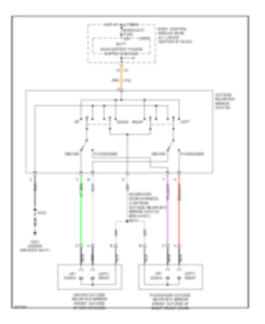
POWER MIRRORS Power Mirrors Wiring Diagram for Saturn Ion Red Line 2005 List of elements for Power Mirrors Wiring Diagram for Saturn Ion Red Line 2005: 19 (in driver's door harness, 4 cm from outside rearview mirror switch breakout) s511 Batt Bcm elect fuse 20a Body control module (bcm) (at lower center of dash) Down Driver Driver outside rearview mirror (front outside of driver door) G301 (under driver's seat) Hot at all times Left Left/ right Logic Nca Outside rearview mirror switch Passenger Passenger outside rearview mirror (front outside of right front door) Right S533 Up/ down
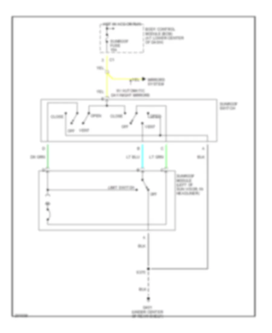
POWER TOP/SUNROOF Power Top/Sunroof Wiring Diagram for Saturn Ion Red Line 2005 List of elements for Power Top/Sunroof Wiring Diagram for Saturn Ion Red Line 2005: 15 Body control module (bcm) (at lower center of dash) Close G401 (under center of rear shelf) Hot in acc or run Limit switch Mirrors system Off Open S375 Sunroof fuse 15a Sunroof module (left of sun visor, in headliner) Sunroof switch Vent Vent off W/ automatic day/night mirrors
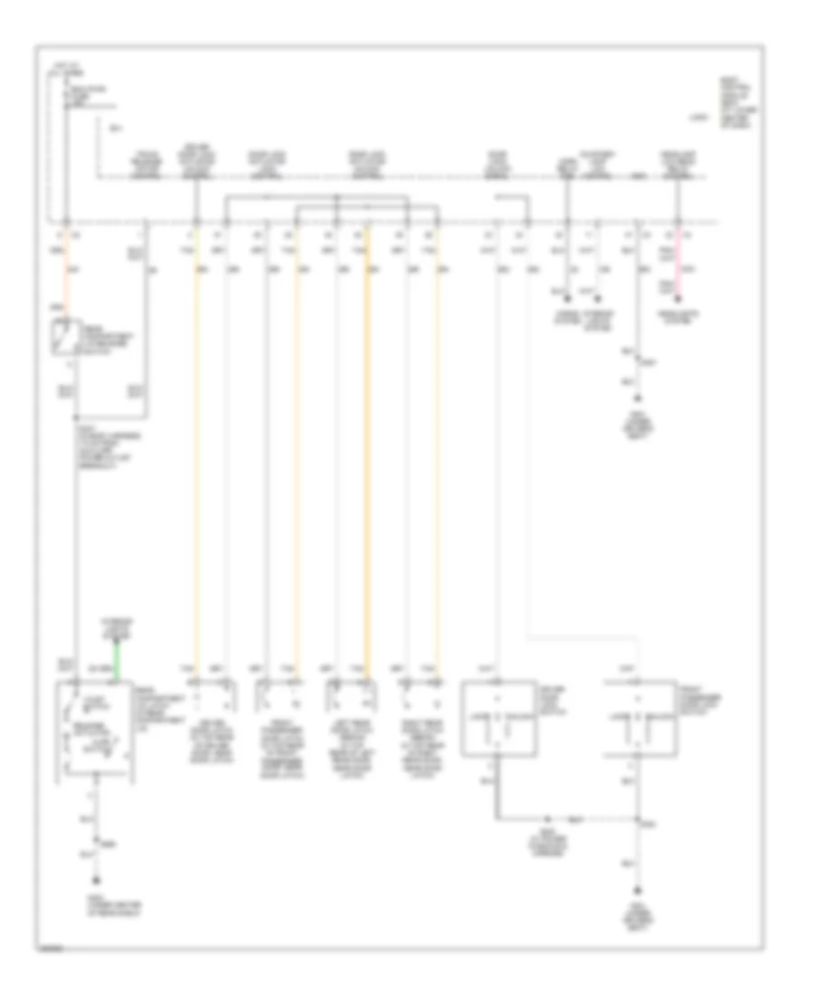
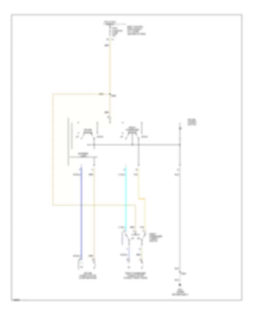
POWER WINDOWS Power Windows Wiring Diagram, Coupe for Saturn Ion Red Line 2005 List of elements for Power Windows Wiring Diagram, Coupe for Saturn Ion Red Line 2005: 15 Body control module (bcm) (at lower center of dash) Down Driver switch Driver window motor (in driver door) Driver window switch Express logic Front passenger switch Front passenger window motor (in right front door) Front passenger window switch G301 (under driver's seat) Hot in acc or run Pwr windows fuse 30a S360 S533 Tan
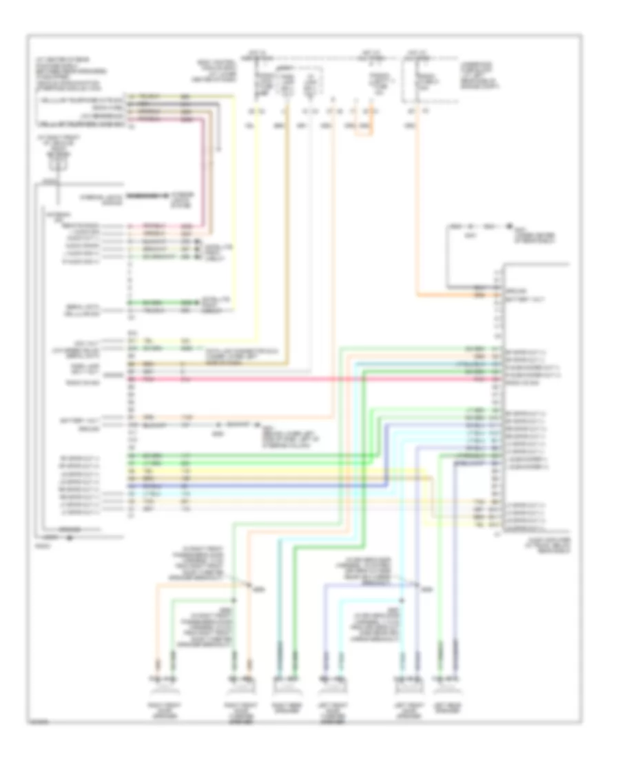
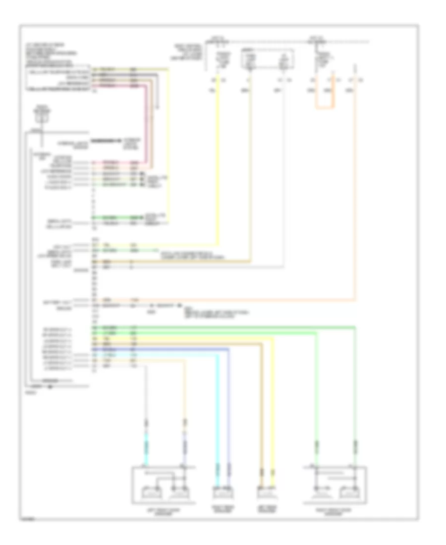
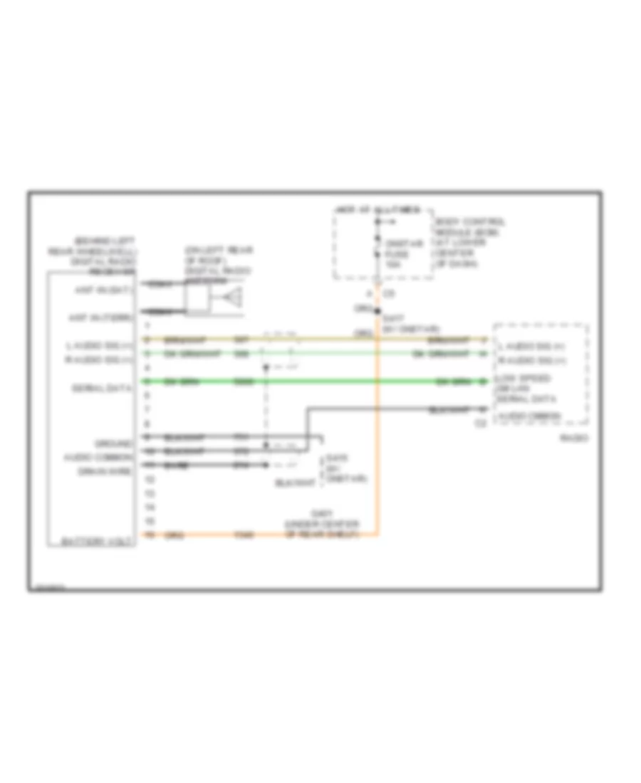
RADIO Radio Wiring Diagram, with Amplifier for Saturn Ion Red Line 2005 List of elements for Radio Wiring Diagram, with Amplifier for Saturn Ion Red Line 2005: 75 (at center of rear package shelf, between rear speakers) (if equipped) vehicle communication interface module (vcim) (at right front of vehicle) radio antenna (in driver's door harness, 19 cm from driver's outside rearview mirror breakout) (in right front passenger's door harness, 13 cm from right front door tweeter speaker breakout) A10 A11 A12 Acc volt Antenna sig Audio amplifier (in trunk, below rear shelf) Audio cmmon Audio out (-) B10 B11 B12 B7 dimming Bare Battery volt Body control module (bcm) (at lower center of dash) Case interior lights dimming Cellular sig Cellular telephone mute sig Cellular telephone voice sig Coax Data link connector (dlc) (under lower left side of dash) Drain wire G201 (behind lower left side of dash, left of steering column) G401 (under center of rear shelf) Ground Hot at all times Hot in acc or run I/p lamp sply volt Interior lights system L audio sig (+) L subwoofer (+) L subwoofer (-) Left front door speaker Left front door tweeter speaker Left rear speaker Lf spkr out (+) Lf spkr out (-) Logic Low reference Low speed gmlan serial data Lr spkr out (+) Lr spkr out (-) Nca Park lamp sply volt Pnk R audio sig (+) R subwoofer out (+) R subwoofer out (-) Radio Radio (acc) fuse 10a Radio (batt 1) fuse 10a Radio fuse 21 20a Radio on sig Remote radio l audio sig Rf spkr out (+) Rf spkr out (-) Right front door speaker Right front door tweeter speaker Right rear speaker Rr spkr out (+) Rr spkr out (-) S250 S401 S555 S557 (in driver's door harness, 11.5 cm from driver's out side rearview mirror breakout) S656 S658 (in right front passenger's door harness, 5.5 cm from right front door tweeter speaker breakout) Satellite radio circuit Serial data Tan Underhood fuse block ( at left rear side of engine compt) Radio Wiring Diagram, without Amplifier for Saturn Ion Red Line 2005 List of elements for Radio Wiring Diagram, without Amplifier for Saturn Ion Red Line 2005: 56 (at center of rear package shelf, between rear speakers) (if equipped) vehicle communication interface module (vcim) A10 A11 A12 Acc volt Antenna sig Audio cmmon B10 B11 B12 Bare Battery volt Body control module (bcm) (at lower center of dash) Case Cellular sig Cellular telephone mute sig Cellular telephone voice sig Coax Data link connector (dlc) (under lower left side of dash) Dimming Drain wire G201 (behind lower left side of dash, left of steering column) Ground Hot at all times Hot in acc or run I/p lamp sply volt Interior lights dimming Interior lights system L audio sig (+) Left front door speaker Left rear speaker Lf spkr out (+) Lf spkr out (-) Logic Low reference Lr spkr out (+) Lr spkr out (-) Nca Park lamp sply volt R audio sig (+) Radio Radio (acc) fuse 10a Radio (batt 1) fuse 10a Radio antenna Rf spkr out (+) Rf spkr out (-) Right front door speaker Right rear speaker Rr spkr out (+) Rr spkr out (-) S250 Satellite radio circuit Serial data Serial data low speed gmlan Tan Voice sig cellular telephone Satellite Radio Wiring Diagram for Saturn Ion Red Line 2005 List of elements for Satellite Radio Wiring Diagram for Saturn Ion Red Line 2005: 22 (behind left rear wheelwell) digital radio receiver (on left rear of roof) digital radio antenna Ant in (sat) Ant in (terr) Audio cmmon Audio common Bare Battery volt Body control module (bcm) (at lower center of dash) C5 a Coax Drain wire G401 (under center of rear shelf) Gm lan serial data Ground Hot at all times L audio sig (+) Low speed b Onstar fuse 10a R audio sig (+) Radio Serial data
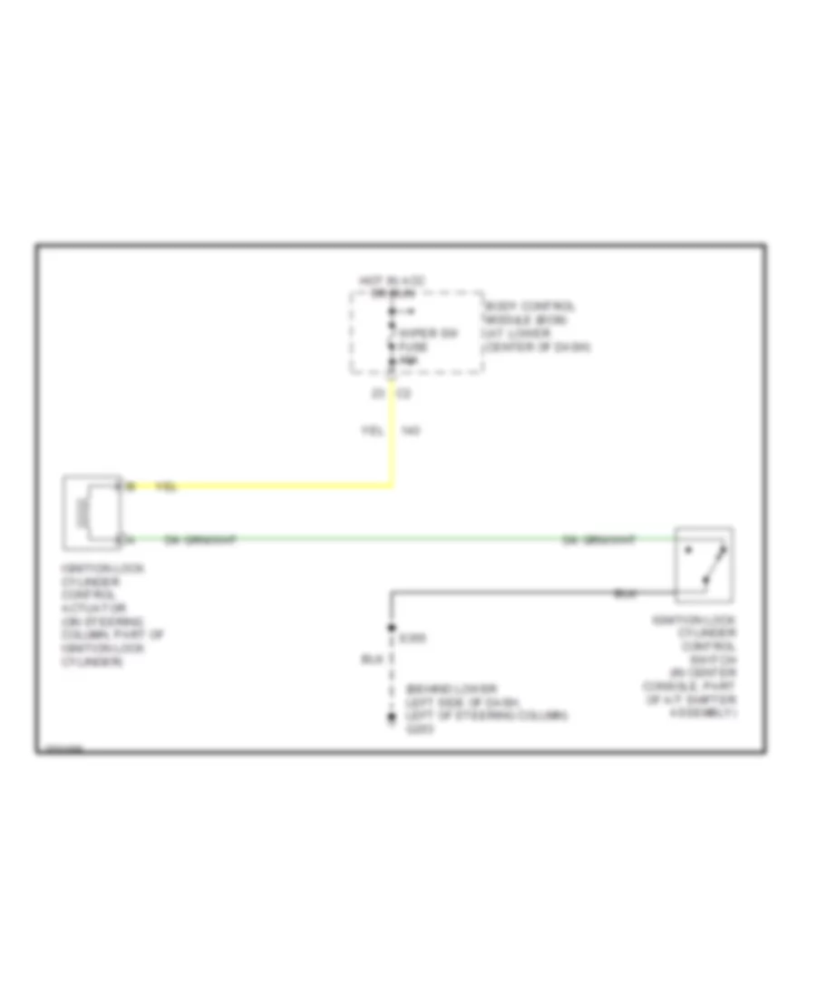
SHIFT INTERLOCK Ignition Lock Solenoid Wiring Diagram for Saturn Ion Red Line 2005 List of elements for Ignition Lock Solenoid Wiring Diagram for Saturn Ion Red Line 2005: 7 (behind lower left side of dash, left of steering column) g203 Body control module (bcm) (at lower center of dash) Hot in acc or run Ignition lock cylinder control actuator (on steering column, part of ignition lock cylinder) Ignition lock cylinder control switch (in center console, part of a/t shifter assembly) S355 Wiper sw fuse 10a
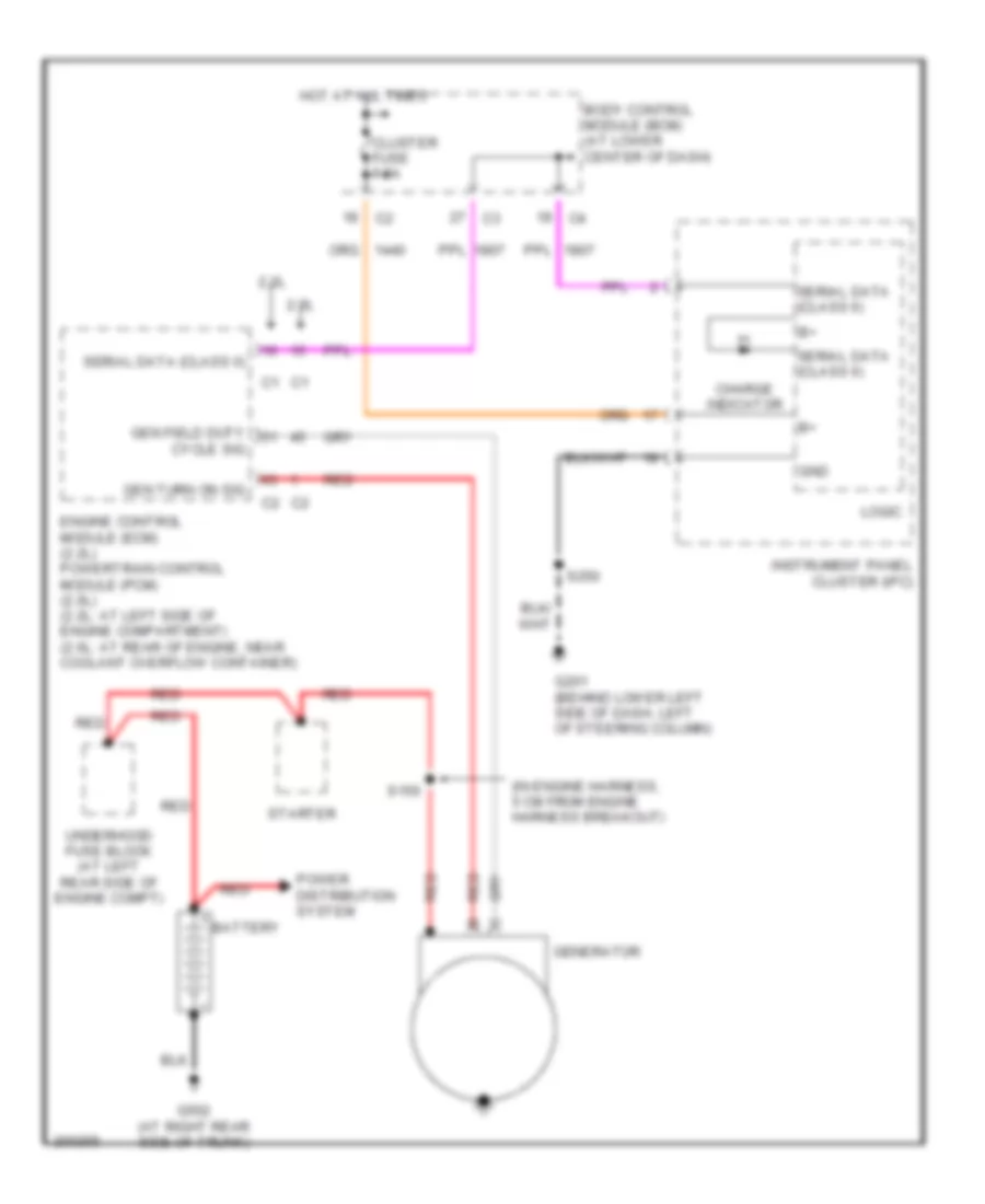
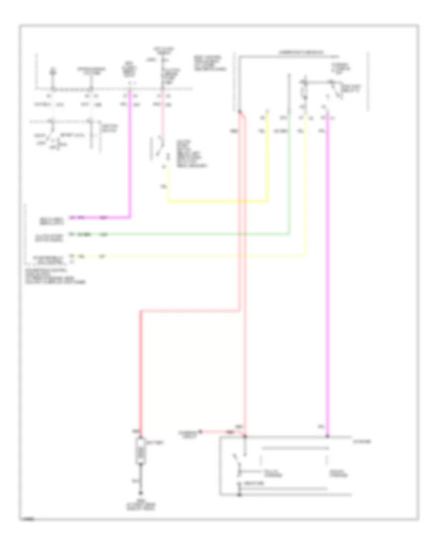
STARTING/CHARGING Charging Wiring Diagram for Saturn Ion Red Line 2005 List of elements for Charging Wiring Diagram for Saturn Ion Red Line 2005: 25 (in engine harness, 5 cm from engine harness breakout) 2.0l 2.2l Battery Body control module (bcm) (at lower center of dash) Charge indicator Cluster fuse 7.5a Cycle sig Engine control module (ecm) (2.2l) powertrain control module (pcm) (2.0l) (2.2l: at left side of engine compartment) (2.0l: at rear of engine, near coolant overflow container) G201 (behind lower left side of dash, left of steering column) G502 (at right rear side of trunk) Gen field duty Gen turn on sig Generator Gnd Hot at all times Instrument panel cluster (ipc) Logic Power distribution system Red S150 S250 Serial data (class ii) Starter Underhood fuse block (at left rear side of engine compt) Starting Wiring Diagram for Saturn Ion Red Line 2005 List of elements for Starting Wiring Diagram for Saturn Ion Red Line 2005: 31 5v ref Acc Armature m B10 Battery Bcm class 2 serial data Body control module (bcm) (at lower center of dash) Charging circuit Clutch start switch (below left side of dash, on clutch pedal bracket) Clutch start switch signal Clutch/ brake fuse 7.5a Crank fuse 46 30a Ecm class 2 serial data G502 (at right rear side of trunk) Hold-in windings Hot in acc or run Ignition switch Lock Logic Off Off/run/crank voltage Pcm cont relay 31 Pnk Powertrain control module (pcm) (at rear of engine, near coolant overflow container) Pull-in windings Red Run Start Starter Starter relay coil control Underhood fuse block
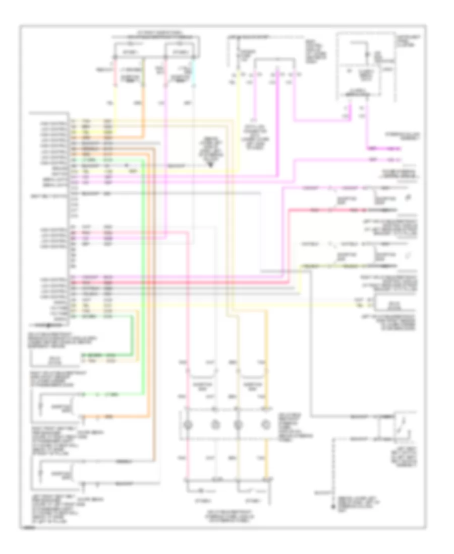
SUPPLEMENTAL RESTRAINTS Supplemental Restraints Wiring Diagram for Saturn Ion Red Line 2005 List of elements for Supplemental Restraints Wiring Diagram for Saturn Ion Red Line 2005: 51 (at right side of dash) (behind lower left side of dash, left of steering column) g201 A10 A11 A12 A13 A14 A15 A16 A17 A18 Air bag fuse 10a Air bag indicator Body control module (at lower center of dash) Case ground Class 2 serial data Coupe Data link connector (dlc) (under lower left side of dash) Ground High control Hot in run or start Ignition Inflatable restraint ip module Inflatable restraint sensing & diagnostic module (sdm) (under center console, behind emergency brake) Inflatable restraint steering wheel module (on steering wheel) Inflatable restraint steering wheel module coil (behind steering wheel) Instrument panel cluster Left front seat belt pretensioner (coupe: at left front side of passenger compt, attached to roof rail) (sedan: at base of left "b" pillar) Left inflatable restraint roof rail module (at left rear side of roof bracket, in "c" pillar) Left inflatable restraint side impact sensor (in lower corner of driver's door) Left seat belt switch (in left seat belt buckle assembly) Logic Low control Nca Pnk Power steering control module Right front seat belt pretensioner (coupe: at right front side of passenger compt, attached to roof rail) (sedan: at base of right "b" pillar) Right inflatable restraint roof rail module (at right rear side of roof bracket, in "c" pillar) Right inflatable restraint side impact sensor (in lower corner of passenger's door) S221 Seat belt switch Sedan Serial data Shorting bar Signal Solid state Stage 1 Stage 2 Steering column assembly Tan Voltage
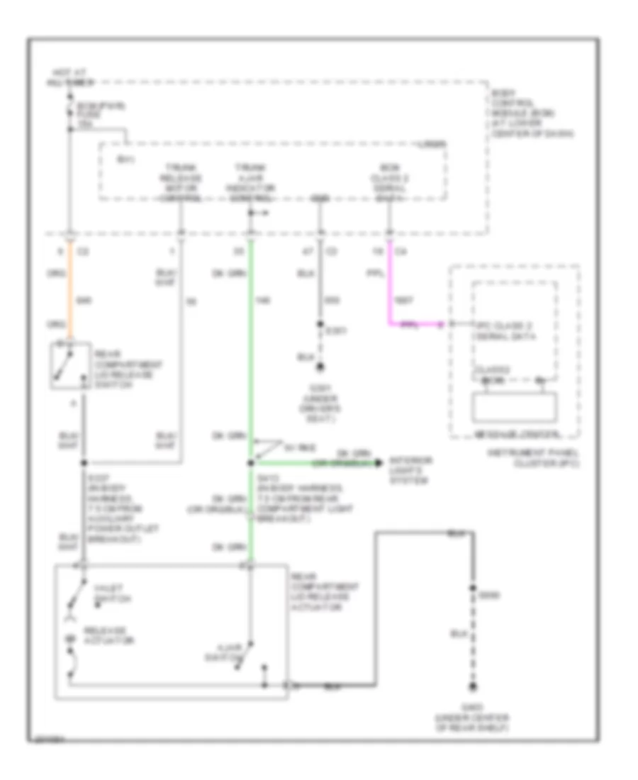
TRUNK, TAILGATE, FUEL DOOR Trunk Release Wiring Diagram for Saturn Ion Red Line 2005 List of elements for Trunk Release Wiring Diagram for Saturn Ion Red Line 2005: 26 Ajar switch B(+) Bcm (pwr) fuse 15a Bcm class 2 serial data Body control module (bcm) (at lower center of dash) Class2 (bcm) Compartment light breakout) G301 (under driver's seat) G403 (under center of rear shelf) Gnd Hot at all times Instrument panel cluster (ipc) Interior lights system Ipc class 2 serial data Logic Message center Rear compartment lid release actuator Rear compartment lid release switch Release actuator S337 (in body harness, 7.5 cm from auxiliary power outlet breakout) S351 S990 Trunk ajar indicator control Trunk release motor control Valet switch W/ rke
WARNING SYSTEMS Warning Systems Wiring Diagram for Saturn Ion Red Line 2005 List of elements for Warning Systems Wiring Diagram for Saturn Ion Red Line 2005: 36 A11 A14 Acc Auto Body control module (bcm) (at lower center of dash) Chime Class 2 (sdm) Class 2 serial data Driver door jamb switch (left front of dash, on outer trim cover) Driver dr jamb sw sig Exterior lights system G201 (behind lower left side of dash, left of steering column) Head Hot at all times Ign sw fuse 2a Ignition switch Inflatable restraint sensing & diagnostic module (sdm) (under center console, behind emergency brake) Instrument panel cluster (ipc) Key-in switch Left seat belt switch (in left seat belt buckle assembly) Left turn sig lp pwr Lock off Logic Nca Off Park Park fuse 15a Park lamps pwr Right turn sig lp pwr Run S221 S250 Seat belt ind Seat belt switch Start Turn signal/ multi- function switch
WIPER/WASHER Wiper/Washer Wiring Diagram for Saturn Ion Red Line 2005 List of elements for Wiper/Washer Wiring Diagram for Saturn Ion Red Line 2005: 41 (not used) A10 c3 B11 Body control module (bcm) (at lower center of dash) D10 c1 D10 c2 F10 F11 G101 (behind left front headlamp) High Hot at all times Hot in acc or run Int L10 L11 Logic Low M11 Mist Off Park switch Q10 Q11 R11 Red S101 Underhood fuse block (at left rear side of engine compartment) Wash Windshield washer fluid pump (on bottom of washer fluid reservoir) Windshield washer pump control Windshield wiper motor assembly (at left rear side of engine compartment) Windshield wiper motor park switch signal Windshield wiper switch signal 1 Windshield wiper switch signal 2 Windshield wiper/washer switch Wiper 1 relay Wiper 2 relay Wiper diode Wiper fuse 19 25a Wiper sw fuse 10a X10