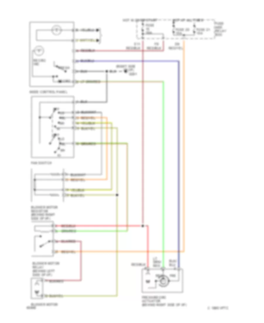
AIR CONDITIONING
A/C Wiring Diagram for Subaru Impreza L 1994

List of elements for A/C Wiring Diagram for Subaru Impreza L 1994:
- (left side of engine compartment)
- (right radiator support)
- (right side
- A/c switch
- A11
- A23
- Acc
- Air conditioner fuse 10a
- Air conditioning cut relay (right side of safety wall)
- Air conditioning relay (in main fuse box)
- Blower motor
- Blower motor relay (behind left side of i/p)
- Blower motor resistor (behind right side of i/p)
- C 1995 vftc
- Clutch
- Compressor
- Diode
- Diode (a/c) (behind left side of i/p)
- Diode (a/c) (left rear of engine compartment)
- E11
- Evaporation thermoswitch (behind right side of i/p)
- F19
- Fan switch
- Fre
- Fresh
- Fresh/recirc actuator (behind right side of i/p)
- Fuse 10a
- Fuse 20 15a
- Fuse 20a
- Fuse 21 15a
- Fuse and relay box
- G109
- G201
- Hot at all times
- Hot in on or start
- Ignition switch
- Interior lights system
- Main fan motor
- Main fan relay
- Main fan relay 2 (in main fuse box)
- Main fuse box
- Mfi control unit (behind right side of i/p)
- Mode control panel
- Nca
- Of i/p)
- Off
- Pressure switch
- Rec
- Recirc
- Recirc ind.
- Run
- Start
- Sub fan motor
- Sub-fan relay 1 (in main fuse box)
- Sub-fan relay 2 (in main fuse box)
- Thermal protector
Heater Wiring Diagram for Subaru Impreza L 1994
List of elements for Heater Wiring Diagram for Subaru Impreza L 1994:
- (right side
- Blower motor
- Blower motor relay (behind left side of i/p)
- Blower motor resistor (behind right side of i/p)
- C 1995 vftc
- E11
- Fan switch
- Fre
- Fresh
- Fresh/recirc actuator (behind right side of i/p)
- Fuse 10a
- Fuse 20 15a
- Fuse 21 15a
- Fuse and relay box
- G201
- Hot at all times
- Hot in on or start
- Mode control panel
- Of i/p)
- Off
- Rec
- Recirc
- Recirc ind.
ANTI-LOCK BRAKES
Anti-lock Brake Wiring Diagrams for Subaru Impreza L 1994
List of elements for Anti-lock Brake Wiring Diagrams for Subaru Impreza L 1994:
- (left shock tower)
- (mt only) abs g sensor (right rear of engine compartment)
- (top of brake pedal support)
- (w/cruise)
- 13
- Abs check (below left side of i/p)
- Abs control unit (rear of engine compartment)
- Abs ind
- At control module (behind left side of i/p)
- B34
- B53
- Brake fluid level switch (left rear of engine comp)
- Brk ind
- Check conn (left kick panel)
- Chk conn
- F18
- F36
- F43
- Fuse 12 20a
- Fuse 15 10a
- Fuse 18 10a
- Fuse 19 20a
- G sensr
- G102
- G102 (left shock tower)
- G109 (right radiator support)
- G300 (below left front seat)
- Gnd
- Hot at all times
- Hot in on or start
- Hydraulic unit (right front fender)
- I17
- I18
- Indicators
- Instrument cluster
- Left front wheel sensor
- Left rear wheel sensor
- Lf abs sol
- Lf sensr (hi)
- Lf sensr (lo)
- Lf sol
- Lr sensr (hi)
- Lr sensr (lo)
- Lr sol
- Main fuse box
- Motor mon
- Motor relay
- Motor rly
- Nca
- Parking brake switch
- Pnk
- Pump motor
- R abs sol
- Relay and fuse box
- Relay coil
- Rf abs sol
- Rf sensr (hi)
- Rf sensr (lo)
- Rf sol
- Right front wheel sensor
- Right rear wheel sensor
- Rr sensr (hi)
- Rr sensr (lo)
- Sbf-6 45a
- Shield j/c (left kick panel)
- Stop
- Stop lamp switch
- Valve pwr mon
- Valve relay
- Valve rly
- Warn
- With awd
- With fwd
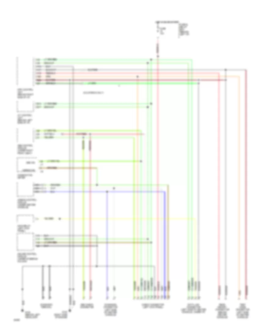
COMPUTER DATA LINES
Computer Data Lines for Subaru Impreza L 1994
List of elements for Computer Data Lines for Subaru Impreza L 1994:
- (california only)
- (left side of center console)
- A/t control unit (behind left side of i/p)
- A14
- A17
- A19
- A20
- Abs check connector
- Abs control module (under right front seat)
- Abs ind
- Airbag control module (under center console)
- Airbag ind
- B14
- B17
- B22
- Check connector (left kick panel)
- Combination meter
- Cruise control module (under steering column)
- Data link connector (left side of center console, under i/p)
- Diagnosis connector
- Diagnosis terminal
- Fuse & relay box (behind left i/p)
- Fuse 10a
- G108 (behind left headlamp)
- G120 (right side of engine)
- Hot in on or start
- I16
- I17
- Main relay (left kick panel)
- Mpfi control unit (behind right side of i/p)
- Nca
- Read memory connector (behind center console)
- Test mode connector (left side of center console)
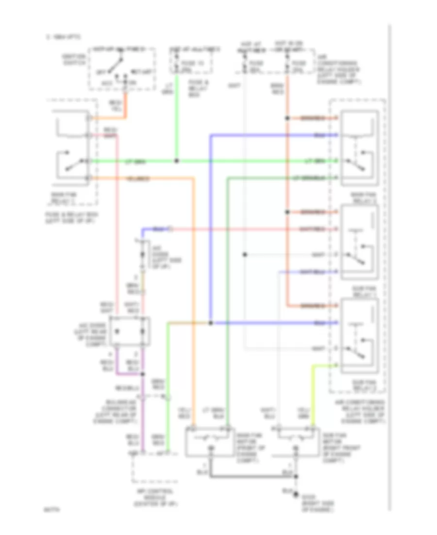
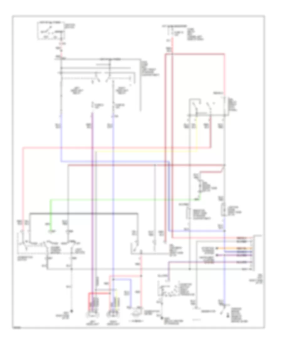
COOLING FAN
Cooling Fan Wiring Diagram, with A/C for Subaru Impreza L 1994
List of elements for Cooling Fan Wiring Diagram, with A/C for Subaru Impreza L 1994:
- 1994 vftc c
- A/c diode (left rear of engine compt)
- A/c diode (left side of i/p)
- A23
- Acc
- Air conditioning relay holder (left side of engine compt)
- Bulkhead connector (left rear of engine compt)
- Fuse & relay box
- Fuse & relay box (left side of i/p)
- Fuse 10a
- Fuse 13 20a
- Fuse 20a
- G120 (right side of engine)
- Hot at all times
- Hot in on or start
- Ignition switch
- Main fan motor (front of engine compt)
- Main fan relay 1
- Main fan relay 2
- Mfi control module (center of i/p)
- Off
- Start
- Sub fan motor (right front of engine compt)
- Sub fan relay 1
- Sub fan relay 2
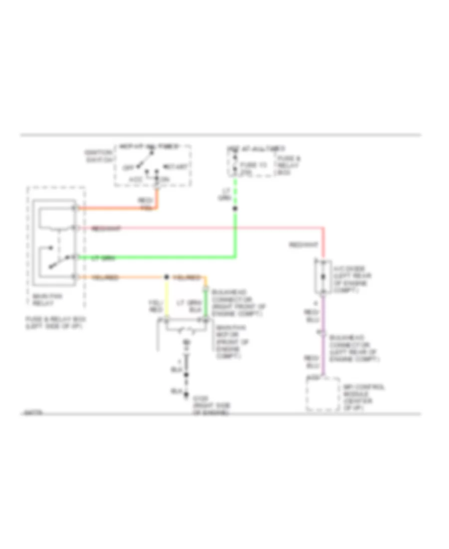
Cooling Fan Wiring Diagram, without A/C for Subaru Impreza L 1994
List of elements for Cooling Fan Wiring Diagram, without A/C for Subaru Impreza L 1994:
- A/c diode (left rear of engine compt)
- A23
- Acc
- Bulkhead connector (left rear of engine compt)
- Bulkhead connector (right front of engine compt)
- Fuse & relay box
- Fuse & relay box (left side of i/p)
- Fuse 13 20a
- G120 (right side of engine)
- Hot at all times
- Ignition switch
- Main fan motor (front of engine compt)
- Main fan relay
- Mfi control module (center of i/p)
- Off
- Start
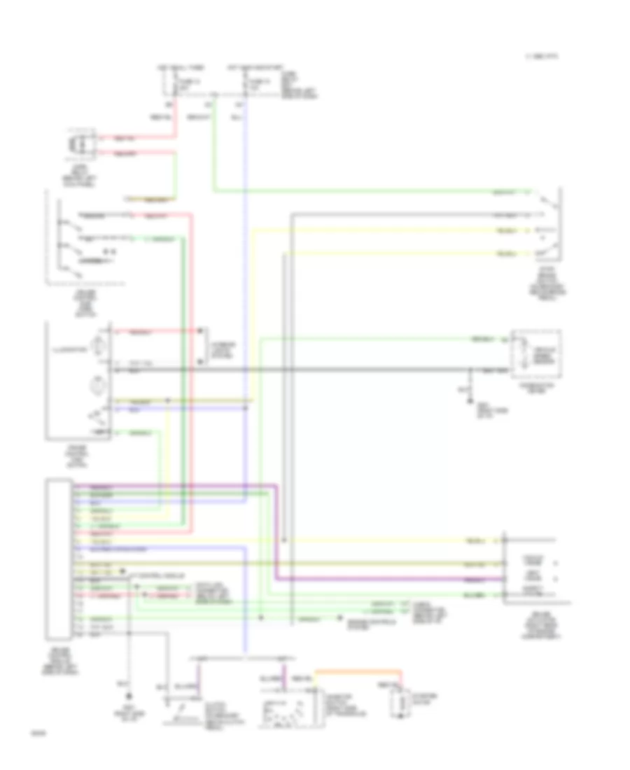
CRUISE CONTROL
Cruise Control Wiring Diagram for Subaru Impreza L 1994
List of elements for Cruise Control Wiring Diagram for Subaru Impreza L 1994:
- A/t
- A/t control module
- C 1995 vftc
- Cancel
- Check connector (behind left side of i/p)
- Clutch switch (on bracket above clutch pedal)
- Combination meter
- Cruise actuator (right rear of engine compartment)
- Cruise control main switch
- Cruise control module (behind left side of dash)
- Cruise control sub/ horn switch
- Data link connector (below left side of dash)
- Engine controls system
- Fuse 12 20a
- Fuse 18 10a
- Fuse/ relay box (behind left side of dash)
- G201 (right side of i/p)
- Horn relay (behind left kick panel)
- Hot at all times
- Hot in on and start
- Illumination
- Inhibitor switch (right side of transaxle)
- Interior lights system
- M/t
- Off
- Resume
- Safety valve
- Set
- Starter motor
- Stop/ brake switch (on bracket above brake pedal)
- Vacuum valve
- Vehicle speed sensor
- Vent valve
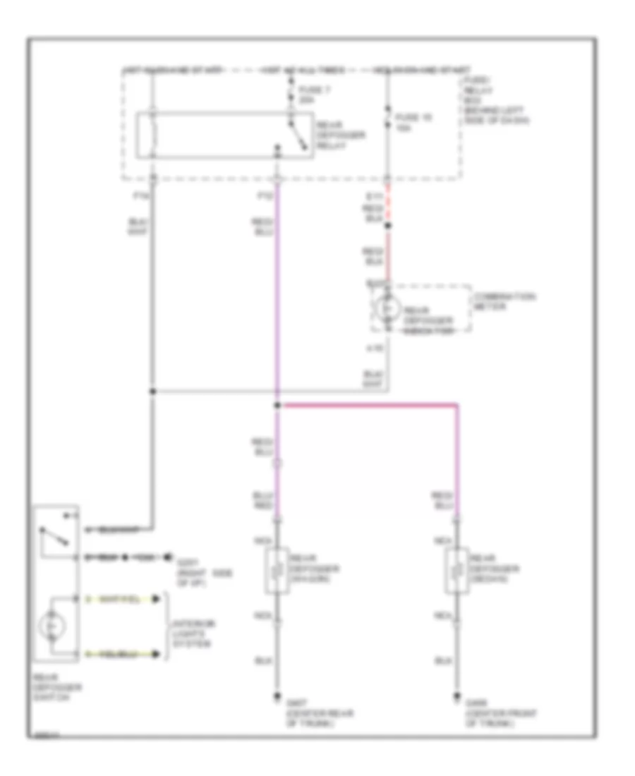
DEFOGGERS
Defogger Wiring Diagram for Subaru Impreza L 1994
List of elements for Defogger Wiring Diagram for Subaru Impreza L 1994:
- A10
- B13
- Combination meter
- E11
- F12
- F14
- Fuse 15 10a
- Fuse 7 20a
- Fuse/ relay box (behind left side of dash)
- G201 (right side of i/p)
- G407 (center rear of trunk)
- G408 (center front of trunk)
- Hot at all times
- Hot in on and start
- Interior lights system
- Nca
- Rear defogger (sedan)
- Rear defogger (wagon)
- Rear defogger indicator
- Rear defogger relay
- Rear defogger switch
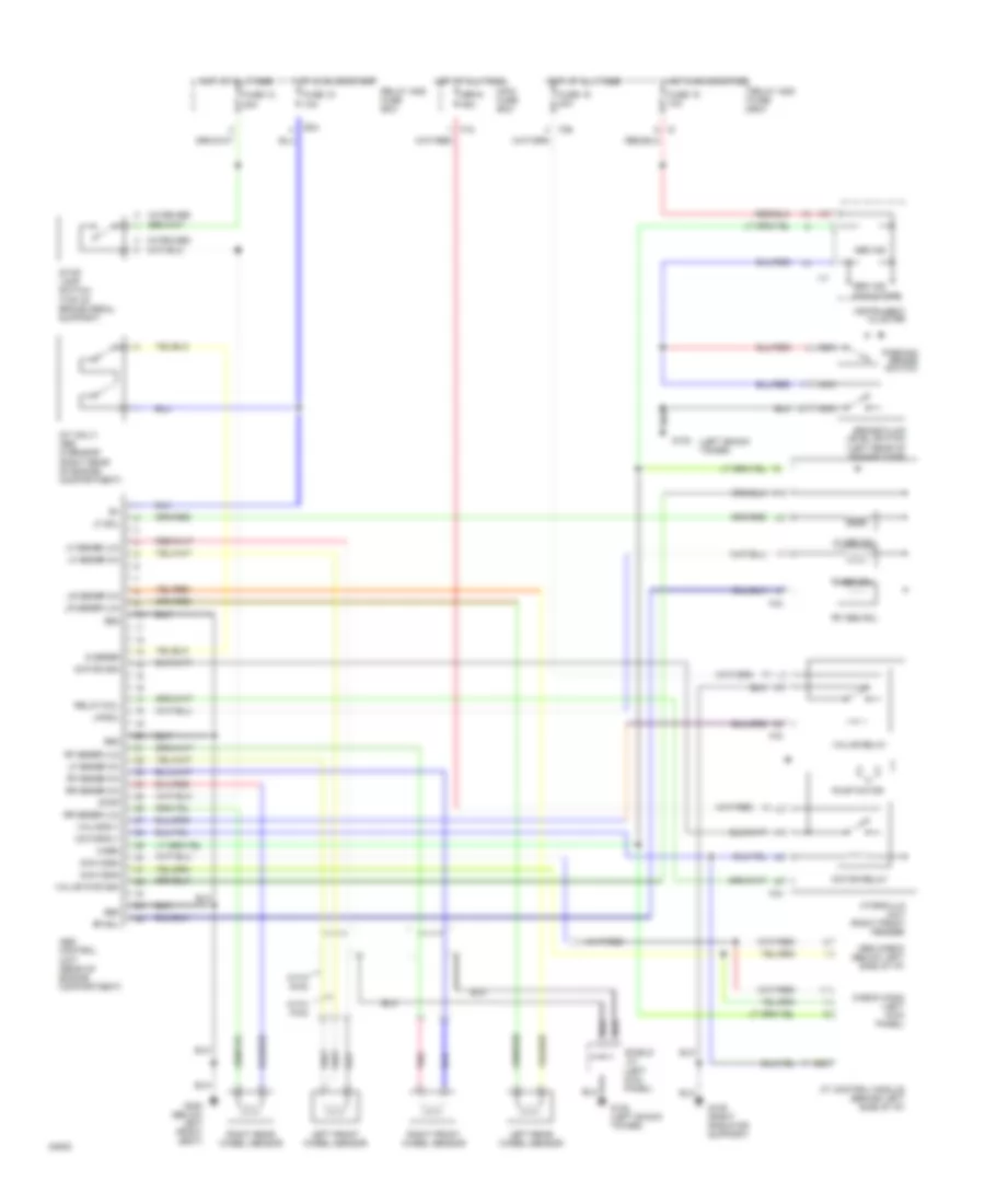
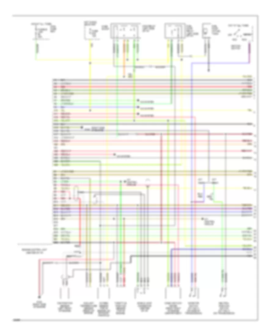
ENGINE PERFORMANCE
1.8L
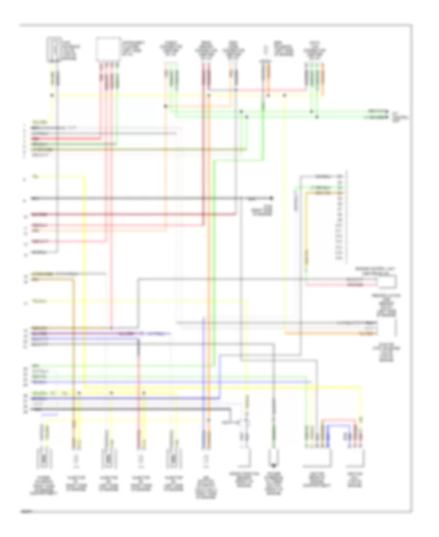
1.8L, Engine Performance Wiring Diagrams (1 of 2) for Subaru Impreza L 1994
List of elements for 1.8L, Engine Performance Wiring Diagrams (1 of 2) for Subaru Impreza L 1994:
- (a/t
- (center of i/p)
- (m/t
- (right side of engine)
- A/c system
- A/t control module
- A10
- A11
- A12
- A13
- A14
- A15
- A16
- A17
- A18
- A19
- A20
- A21
- A22
- A23
- A24
- A25
- A26
- Acc
- B10
- B11
- B12
- B13
- B14
- B15
- B16
- B17
- B18
- B19
- B20
- B21
- B22
- Cam position sensor (left front of engine)
- Coolant temperature sensor (front of engine)
- Engine control unit
- Fuel pump (in fuel tank)
- Fuel pump relay (left side of i/p)
- Fuse #16 15a
- Fuse block
- Fusible link #2 30a
- G120
- G120 (right side of engine)
- Hot at all times
- Hot in run or start
- Ignition switch
- Inhibitor switch (a/t only) (on side of transmission)
- Main fuse box
- Main relay (left side of i/p)
- Mass air flow meter (front right of engine compartment)
- Nca
- Neutral position switch (m/t only) (on transmission)
- Off
- Only)
- Oxygen sensor (top of engine, on exhaust manifold)
- Red
- Run
- Shield joint connector (center of i/p)
- Start
- Throttle position sensor (top of engine)
1.8L, Engine Performance Wiring Diagrams (2 of 2) for Subaru Impreza L 1994
List of elements for 1.8L, Engine Performance Wiring Diagrams (2 of 2) for Subaru Impreza L 1994:
- (calif only) (right side of engine)
- (center of i/p)
- A/t control unit
- A12 red
- Air suction solenoid
- C10
- C11
- C12
- C13
- C14
- C15
- C16
- Check connector (center of i/p)
- Crank position sensor (front of engine)
- Data link connector (center of i/p)
- Egr solenoid (left side of engine)
- Engine control unit
- Ficd solenoid valve (top of engine)
- G120 (right side of engine)
- Idle air ctrl solenoid valve (top of engine)
- Ignition coil (top of engine)
- Ignitor (rear of engine compartment)
- Injector #1 (right side of engine)
- Injector #2 (left side of engine)
- Injector #3 (right side of engine)
- Injector #4 (left side of engine)
- Instrument cluster (left side of i/p)
- Nca
- Power steering/ oil pres switch (front of engine)
- Purge solenoid (right side of engine compartment)
- Read memory connector (center of i/p)
- Recirculation gas sensor (calif) (left side of engine)
- Red
- Test mode connector (center of i/p)
EXTERIOR LIGHTS
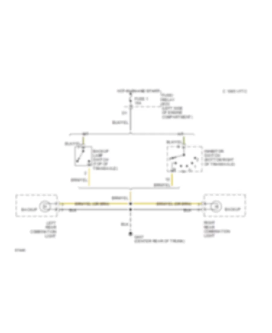
Back-up Lamps Wiring Diagram for Subaru Impreza L 1994
List of elements for Back-up Lamps Wiring Diagram for Subaru Impreza L 1994:
- A/t
- Backup
- Backup lamp switch (top of transaxle)
- C 1995 vftc
- Fuse 1 15a
- Fuse/ relay box (left side of engine compartment)
- G407 (center rear of trunk)
- Hot in on and start
- Inhibitor switch (bottom right of transaxle)
- Left rear combination light
- M/t
- Right rear combination light
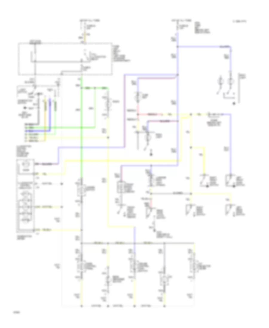
Exterior Light Wiring Diagram for Subaru Impreza L 1994
List of elements for Exterior Light Wiring Diagram for Subaru Impreza L 1994:
- (right side
- A11
- B15
- C 1995 vftc
- Combination meter
- Combination switch
- D10
- D11
- F25
- F28
- Fuse 1 15a
- Fuse 12 20a
- Fuse 22 15a
- Fuse 23 20a
- Fuse 5 10a
- Fuse/ relay box (left side of engine compartment)
- G108 (left radiator support)
- G109 (right radiator support)
- G201
- G201 (right side of i/p)
- G407 (center rear of trunk)
- Hazard switch
- Head
- High mount stop light
- Hot at all times
- Hot in on and start
- Interior lights system
- Left front clearance light
- Left front turn light
- Left license plate light
- Left rear combination lamp
- Left side turn light
- Left turn
- Light switch
- Main fuse box (behind left side of dash)
- Of i/p)
- Off
- Park
- Parking switch
- Red
- Right front clearance light
- Right front turn light
- Right license plate light
- Right rear combination lamp
- Right side turn light
- Right turn
- Sbf-1 fuse 45a
- Stop
- Stop/ brake switch (on brake pedal support)
- Tail
- Tail/ illumination relay
- Turn
- Turn signal switch
- Turn signal/ hazard unit (below left side of i/p)
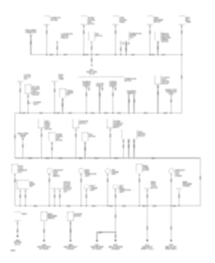
GROUND DISTRIBUTION
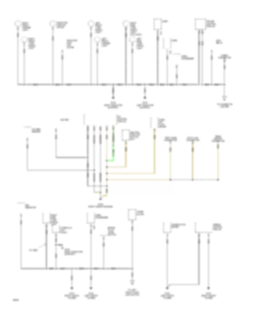
Ground Distribution Wiring Diagram (1 of 2) for Subaru Impreza L 1994
List of elements for Ground Distribution Wiring Diagram (1 of 2) for Subaru Impreza L 1994:
- (w/ abs)
- A14
- A15
- A25
- Airbag control module
- B22
- B75
- Brake fluid level switch
- Check connector
- Combination meter
- Cruise control module
- Data link connector
- Drl resistor
- F12
- F13
- G102 (left shock tower)
- G103 (right shock tower)
- G108 (left radiator support)
- G109 (right radiator support)
- G120 (right side of engine)
- Horn
- Horn condenser
- Hydraulic unit (a.b.s.)
- Igniter
- Left front marker light
- Left front turn signal light
- Left side turn signal light
- Main relay
- Mass air flow meter
- Mfi control module
- Neutral position switch (m/t)
- Oxygen sensor
- Radiator main fan motor
- Radiator sub fan motor
- Read memory connector
- Right front marker light
- Right front turn signal light
- Right side turn signal light
- Right side turn signal light (w/o a.b.s.)
- Test mode connector
- To cigarette lighter
- To left front door lock switch
- Wiper motor
Ground Distribution Wiring Diagram (2 of 2) for Subaru Impreza L 1994
List of elements for Ground Distribution Wiring Diagram (2 of 2) for Subaru Impreza L 1994:
- !18
- !19
- (canada only)
- A.b.s. control module
- A/t shift lock control module
- B15
- B67
- B68
- B69
- Cigarette lighter
- Clutch switch (m/t)
- Combination meter (a/t)
- Combination switch
- Cruise control main switch
- Daytime running light control module
- Diagnosis terminal
- Dimmer & passing switch
- Door lock timer
- Fan switch
- From check connector
- From wiper motor
- Fuel gauge unit
- Fwd switch
- G121 (center of safety wall)
- G201 (right side of i/p)
- G206 (center of i/p)
- G300 (below left front seat)
- G302 (below center console)
- G407 (center rear of trunk)
- G408 (center front of trunk)
- G908 (center front of roof)
- High-mount stop light (sedan)
- High-mount stop light (wagon)
- Illumination control module
- Inhibitor switch
- Left front door lock switch
- Left license light
- Left rear combination light
- Lighting switch
- Manual switch & park position switch (a/t)
- Mode control panel
- Power window & sunroof relay
- Power window main switch
- Radio
- Rear defogger (sedan)
- Rear defogger (wagon)
- Rear defogger switch
- Rear gate latch switch
- Rear wiper motor
- Remote control rearview mirror switch
- Right license light
- Right rear combination light
- Seat belt timer
- Shield joint connector (a.b.s.)
- Shift lock solenoid (a/t)
- Sunroof switch
- Turn & hazard unit
- Wiper & washer switch
HEADLIGHTS
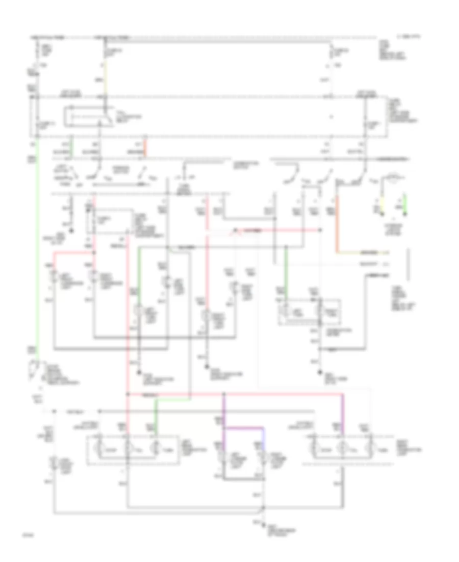
Headlight Wiring Diagram, with DRL for Subaru Impreza L 1994
List of elements for Headlight Wiring Diagram, with DRL for Subaru Impreza L 1994:
- Acc
- B66
- B67
- Combination meter
- Combination switch
- Dimmer/ passing switch
- Drl diode (right side of i/p)
- Drl high-beam relay (right side of i/p)
- Drl relay (right kick panel)
- Drl unit (right side of i/p)
- E11
- F28
- F63
- Fuse 15 10a
- Fuse 24 15a
- Fuse 26 15a
- Fuse/ relay box (under left side of dash)
- G201 (right side of i/p)
- G302 (below center of console)
- Generator
- Head
- Hi beam
- Hot at all times
- Hot in on and start
- Ignition switch
- Inhibitor switch (right side of transaxle)
- Instrument cluster system
- Left headlight
- Left headlight relay
- Light switch
- Lighting diode (right side of i/p)
- Main fuse box (left front of engine compartment)
- Off
- Park
- Parking brake switch (base of parking brake lever)
- Pass
- Red
- Red f27
- Resistor (right side of engine compartment)
- Right headlight
- Right headlight relay
- Start
- Starting/ charging system
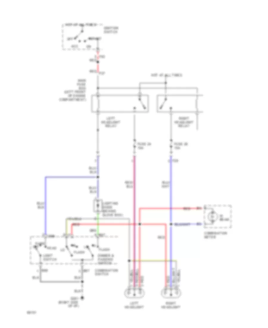
Headlight Wiring Diagram, without DRL for Subaru Impreza L 1994
List of elements for Headlight Wiring Diagram, without DRL for Subaru Impreza L 1994:
- Acc
- B66
- B67
- Combination meter
- Combination switch
- Dimmer & passing switch
- F28
- F63 red
- Flash
- Fuse 24 15a
- Fuse 26 15a
- G201 (right side of i/p)
- Head
- Hi beam
- Hot at all times
- Ignition switch
- Left headlight
- Left headlight relay
- Light switch
- Lighting diode (behind glove box)
- Main fuse box (left front of engine compartment)
- Off
- Park
- Red
- Red f27
- Right headlight
- Right headlight relay
- Start
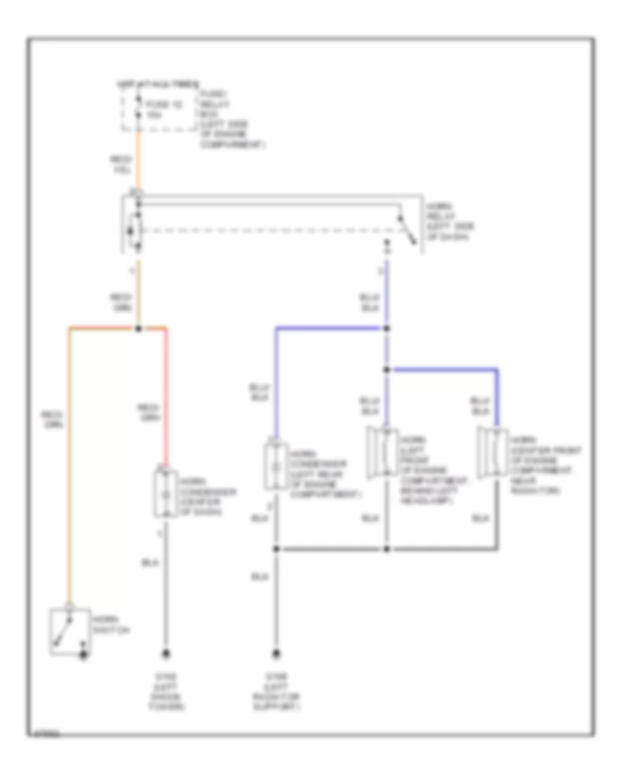
HORN
Horn Wiring Diagram for Subaru Impreza L 1994
List of elements for Horn Wiring Diagram for Subaru Impreza L 1994:
- Fuse 12 15a
- Fuse/ relay box (left side of engine comparment)
- G102 (left shock tower)
- G108 (left radiator support)
- Horn (center front of engine comparment, near radiator)
- Horn (left front of engine compartment, behind left headlamp)
- Horn condenser (center of dash)
- Horn condenser (left rear of engine compartment)
- Horn relay (left side of dash)
- Horn switch
- Hot at all times
INSTRUMENT CLUSTER
Instrument Cluster Wiring Diagram for Subaru Impreza L 1994
List of elements for Instrument Cluster Wiring Diagram for Subaru Impreza L 1994:
- (center rear
- (left shock
- A10
- A11
- A12
- A13
- A14
- A15
- A16
- A22
- Abs
- Airbag control module
- Airbag warning
- Alternator
- Anti-lock brake control unit
- B10
- B11
- B12
- B13
- B14
- B15
- B16
- Brake
- Brake fluid level sensor (in brake master cylinder)
- Buzzer
- C 1995 vftc
- Charge
- Check engine
- D10
- Door
- Engine control module (behind center of dash)
- Engine controls system
- Engine coolant temperature sensor (right rear of engine)
- Exterior lights system
- F10
- Fuel gauge
- Fuel gauge unit (in fuel tank)
- Fuse 15 15a
- Fuse 25 10a
- Fuse 26 15a
- Fuse 9 10a
- Fuse box (behind left side of dash)
- Fwd
- G102
- G102 (left shock tower)
- G201 (right side of i/p)
- G302 (below center console)
- G407
- Headlight relay energized
- Headlights system
- Headlights system (canada)
- Hi beam
- Hot at all times
- Hot in on and start
- Hot with right
- Hot with tail & illumination relay energized
- Illumination (5 bulbs)
- Illumination control unit
- Inhibitor switch (bottom right of transaxle)
- Instrument cluster
- Interior lights system
- Left turn
- Main fuse box (behind left side of dash)
- Manual
- Of trunk)
- Oil
- Oil pressure switch (top right front of engine, behind alternator)
- Parking brake switch (base of parking brake lever)
- Passive restraint system
- Power
- Rear defogger
- Rear defogger switch
- Red
- Right turn
- Seat belt warning
- Speedometer
- Tacho meter
- Temperature gauge
- Tower)
- Transmissions system
- Warnings system
INTERIOR LIGHTS
Interior Light Wiring Diagram for Subaru Impreza L 1994
List of elements for Interior Light Wiring Diagram for Subaru Impreza L 1994:
- A/t selector lever
- A15
- A16
- C 1995 vftc
- Combination meter
- Combination switch
- Cruise control main switch
- D10
- Diode (behind left side of i/p)
- Door
- F28
- Fuse 23 20a
- Fuse 25 10a
- Fuse 9 10a
- Fuse and relay box (left side of engine compartment)
- Fuse box
- G121 (center of safety wall)
- G201 (right side of i/p)
- Hazard switch
- Head
- Hot at all times
- Hot in on and start
- I17
- I18
- I19
- Illumination control circuit(at)
- Illumination control module (in center console)
- Left front door switch
- Left rear door switch
- Light switch
- Luggage room light (wagon)
- Main fuse box (behind left side of dash)
- Mode control panel
- Nca
- Off
- Park
- Radio
- Rear defogger switch
- Rear gate latch switch
- Right front door switch
- Right rear door switch
- Room light
- Spot light
- Tail/ illumination relay
- Trunk room light (sedan)
- Trunk room light switch (sedan)
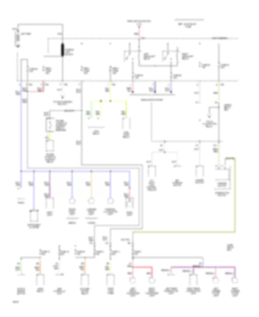
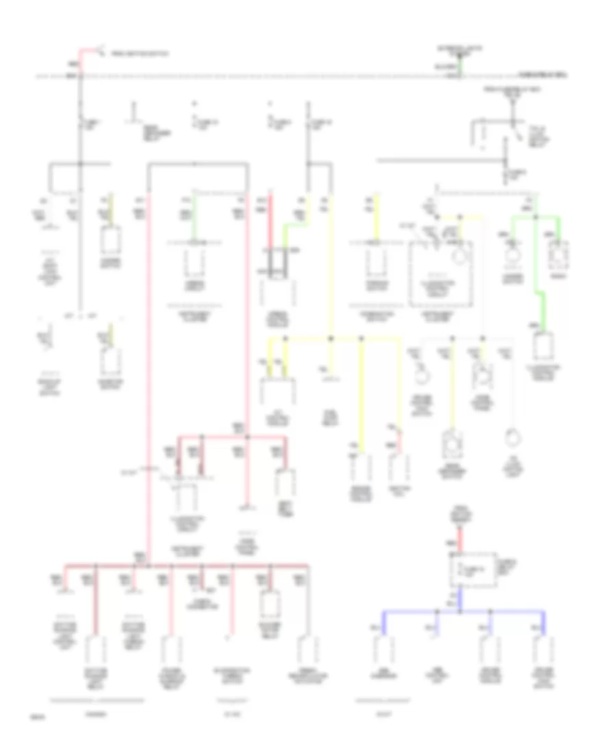
POWER DISTRIBUTION
Power Distribution Wiring Diagram (1 of 3) for Subaru Impreza L 1994
List of elements for Power Distribution Wiring Diagram (1 of 3) for Subaru Impreza L 1994:
- A/t shift lock control module
- Abs hydraulic unit
- Battery
- Blower motor relay
- Combination switch
- D11
- Door lock timer
- F25
- F26
- F27
- F28
- F29
- From ignition switch
- Fuel pump relay
- Fuse
- Fuse & relay box
- Fuse 11 20a
- Fuse 12 20a
- Fuse 19 20a
- Fuse 20 15a
- Fuse 21 15a
- Fuse 22 15a
- Fuse 23 20a
- Fuse 24 15a
- Fuse 25 10a
- Fuse 26 15a
- Fuse 5 10a
- Fuse box illumination light
- Fuse/ relay box
- Fusible link (black)
- Hazard switch
- Headlights system
- Horn relay
- I18
- Instrument cluster
- Key warning switch
- Left front clearance light
- Left headlight relay
- Left license plate light
- Left rear combination light
- Luggage room light
- Main fuse box
- Main relay
- Nca
- Parking switch
- Power window & sunroof circuit breaker
- Power window & sunroof relay
- Radio
- Red
- Right front clearance light
- Right headlight relay
- Right license plate light
- Right rear combination light
- Room light
- Sbf-1 fuse 30a
- Sbf-2 fuse 30a
- Sbf-3 fuse 45a
- Sbf: slow blow
- Sedan
- Spot light
- Stop & brake switch
- Tail & illumination relay
- To main fuse box f29, pin 1
- Trunk room light
- Wagon
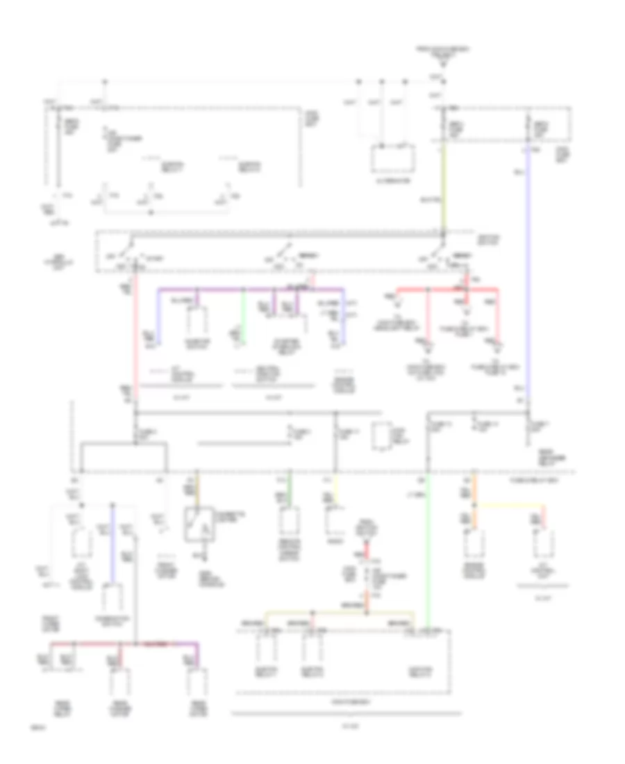
Power Distribution Wiring Diagram (2 of 3) for Subaru Impreza L 1994
List of elements for Power Distribution Wiring Diagram (2 of 3) for Subaru Impreza L 1994:
- (a/t)
- (m/t)
- A/t control module
- A/t control unit
- A/t shift lock control module
- A16
- Abs hydraulic unit
- Acc
- Air conditioner fuse 10a
- Air conditioner fuse 20a
- Alternator
- B12
- Cigarette lighter
- Combination switch
- Engine control module
- F11
- F13
- F18
- F19
- F20
- F21
- F22
- F25
- F29
- F63
- From ignition switch
- From main fuse box f29, pin 2
- Front washer motor
- Front wiper motor
- Fuse & relay box
- Fuse 13 20a
- Fuse 14 10a
- Fuse 17 15a
- Fuse 2 20a
- Fuse 3 15a
- Fuse 7 20a
- G206 (behind console)
- Ignition switch
- Inhibitor switch
- Main fan relay
- Main fan relay-2
- Main fuse box
- Neutral position switch
- Off
- Radio
- Rear defogger relay
- Rear washer motor
- Rear wiper motor
- Rear wiper relay
- Red
- Remote control mirror switch
- Sbf-4 fuse 45a
- Sbf-5 fuse 45a
- Sbf-6 fuse 45a
- Start
- Starter interlock relay
- Sub fan relay-1
- Sub fan relay-2
- Sub-fan relay-1
- Sub-fan relay-2
- To fuse & relay box fuse 1
- To fuse & relay box fuse 18
- To main fuse box a/c fuse (10a) (w/ a/c)
- To main fuse box headlight relay
- W/ a/c
- W/ a/t
- W/ m/t
Power Distribution Wiring Diagram (3 of 3) for Subaru Impreza L 1994
List of elements for Power Distribution Wiring Diagram (3 of 3) for Subaru Impreza L 1994:
- A/t
- A/t control module
- A/t shift lock control unit
- A10
- A15
- A16
- Abs control unit
- Abs g-sensor
- Airbag circuit
- Airbag control module
- B13
- B37
- B39
- Back-up light switch
- Blower motor relay
- Canada
- Cd illum- ination light
- Check connector
- Combination switch
- Cruise control main switch
- Cruise control module
- D10
- Daytime running light control unit
- Daytime running light hi-beam relay
- Daytime running light relay
- E10
- E11
- E12
- Engine control module
- Evaporation thermo switch
- Exterior lights system
- F10
- Fresh/ recirculator actuator
- From fuse/relay box pin a2
- From ignition switch
- Fuel pump relay
- Fuse & relay box
- Fuse 1 15a
- Fuse 15 10a
- Fuse 16 15a
- Fuse 18 10a
- Fuse 8 15a
- Fuse 9 10a
- Hazard switch
- I16
- I19
- Ignition coil
- Illumination control circuit
- Illumination control module
- Inhibitor switch
- Instrument cluster
- M/t
- Mode control panel
- Nca
- Parking switch
- Power window & sunroof relay
- Radio
- Rear defogger relay
- Rear defogger switch
- Red
- Seat belt timer
- Tail & illum- ination relay
- W/ a/c
- W/ a/t
- W/ m/t
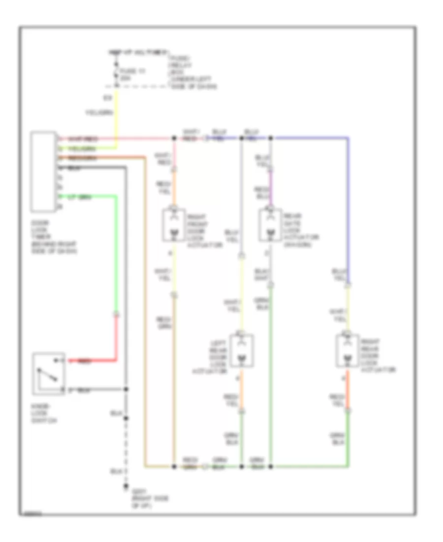
POWER DOOR LOCKS
Power Door Lock Wiring Diagram for Subaru Impreza L 1994
List of elements for Power Door Lock Wiring Diagram for Subaru Impreza L 1994:
- Door lock timer (behind right side of dash)
- Fuse 11 20a
- Fuse/ relay box (under left side of dash)
- G201 (right side of i/p)
- Hot at all times
- Knob- lock switch
- Left rear door lock actuator
- Rear gate lock actuator (wagon)
- Red
- Right front door lock actuator
- Right rear door lock actuator
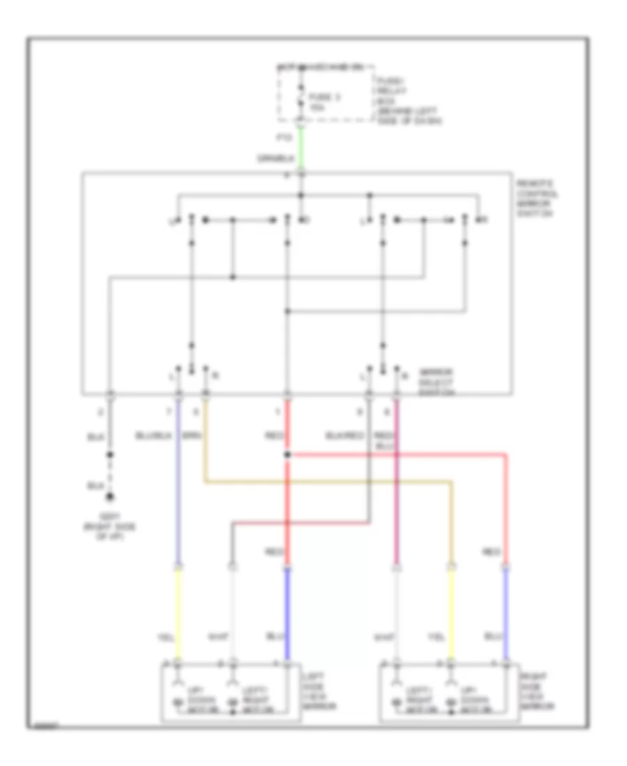
POWER MIRRORS
Power Mirror Wiring Diagram for Subaru Impreza L 1994
List of elements for Power Mirror Wiring Diagram for Subaru Impreza L 1994:
- F13
- Fuse 3 15a
- Fuse/ relay box (behind left side of dash)
- G201 (right side of i/p)
- Hot in acc and on
- Left side view mirror
- Left/ right m
- Mirror select switch
- Motor
- Red
- Remote control mirror switch
- Right side view mirror
- Up/ down m
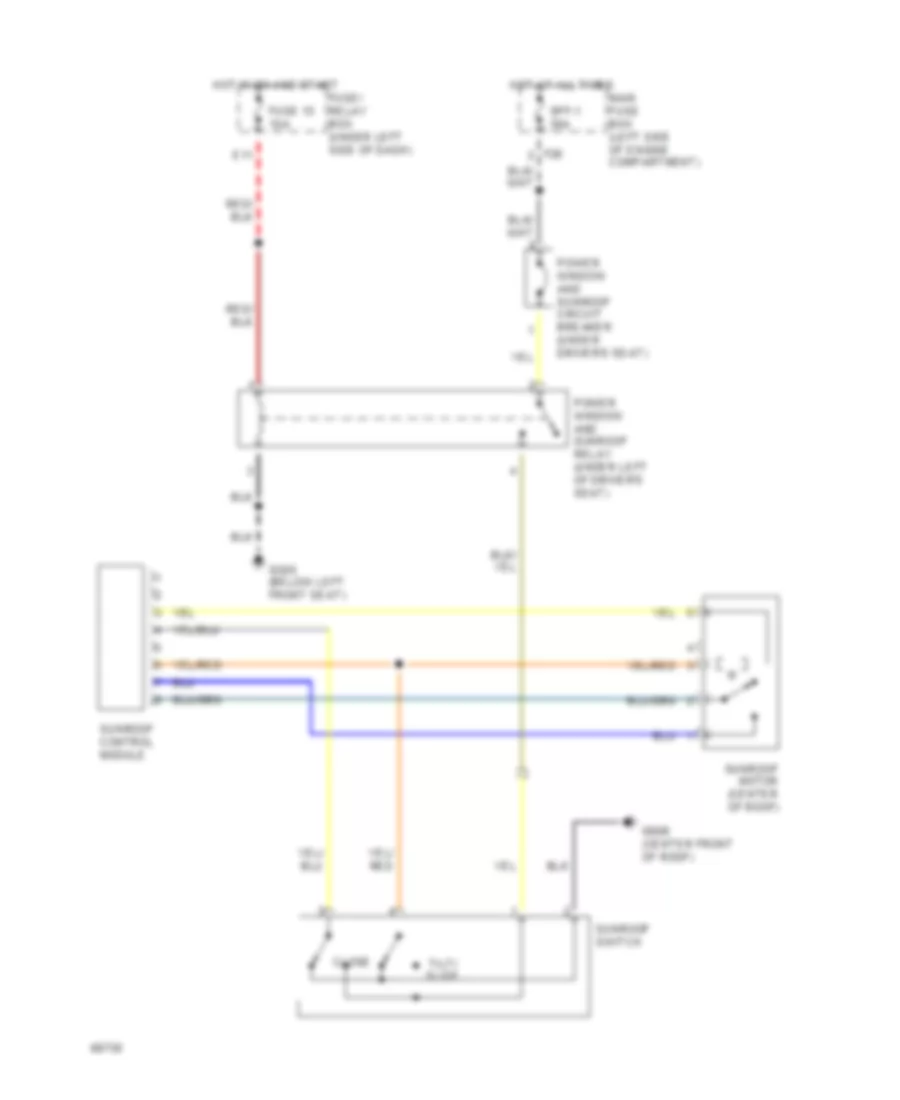
POWER TOP/SUNROOF
Power Top/Sunroof Wiring Diagrams for Subaru Impreza L 1994
List of elements for Power Top/Sunroof Wiring Diagrams for Subaru Impreza L 1994:
- Close
- E11
- F26
- Fuse 15 10a
- Fuse/ relay box (under left side of dash)
- G300 (below left front seat)
- G908 (center front of roof)
- Hot at all times
- Hot in on and start
- Main fuse box (left side of engine compartment)
- Power window and sunroof circuit breaker (under driver's seat)
- Power window and sunroof relay (under left of driver's seat)
- Spf-1 30a
- Sunroof control module
- Sunroof motor (center of roof)
- Sunroof switch
- Tilt/ slide
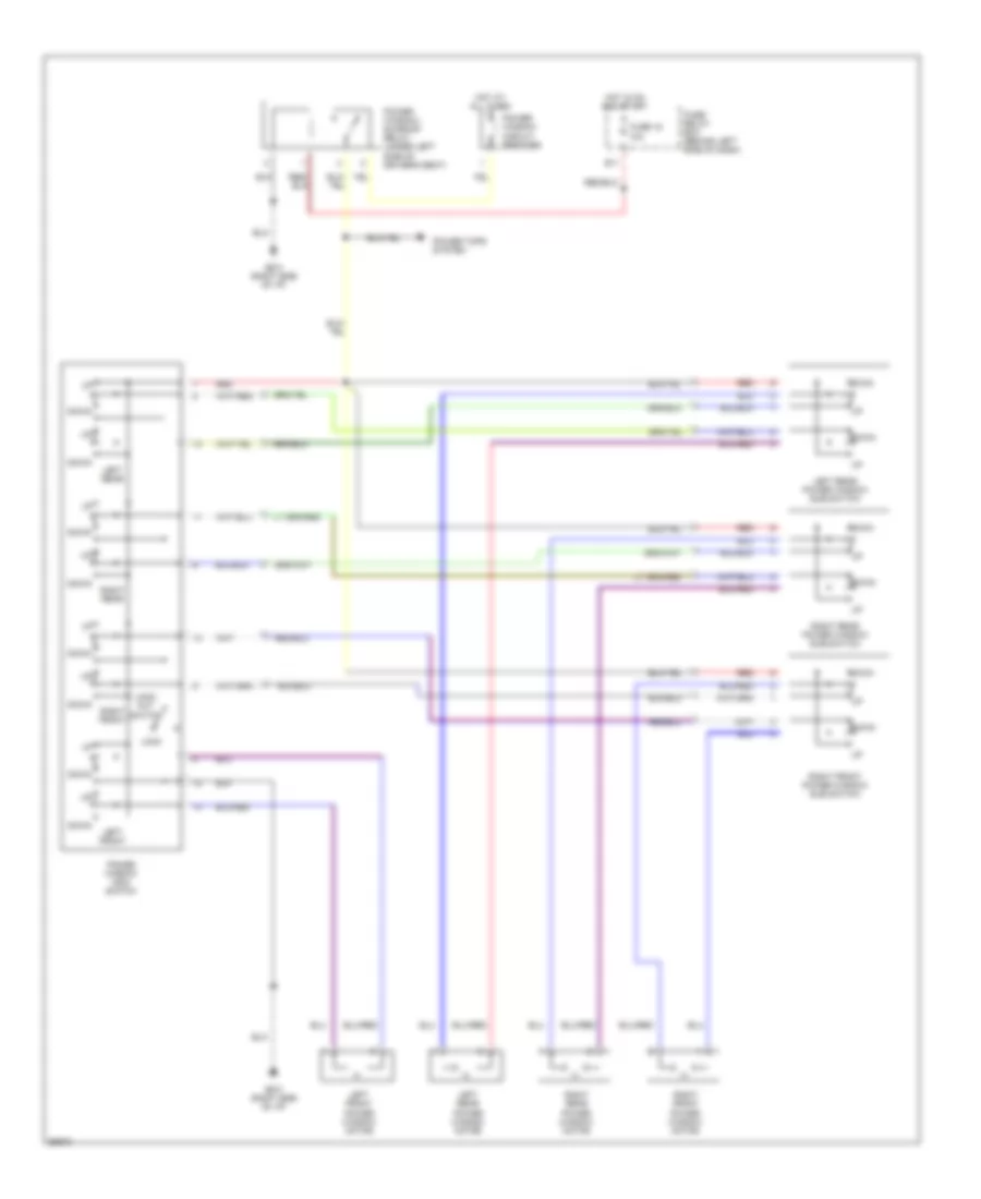
POWER WINDOWS
Power Window Wiring Diagram for Subaru Impreza L 1994
List of elements for Power Window Wiring Diagram for Subaru Impreza L 1994:
- Down
- E11
- Fuse 15 10a
- Fuse/ relay box (behind left side of dash)
- G201 (right side of i/p)
- Hot at all times
- Hot in on and start
- Left front
- Left front power window motor
- Left rear
- Left rear power window motor
- Left rear power window sub switch
- Lock
- Lock- out switch
- Power tops system
- Power window circuit breaker
- Power window main switch
- Power window/ sunroof relay (under left side of driver's seat)
- Red
- Right front
- Right front power window motor
- Right front power window sub switch
- Right rear
- Right rear power window motor
- Right rear power window sub switch
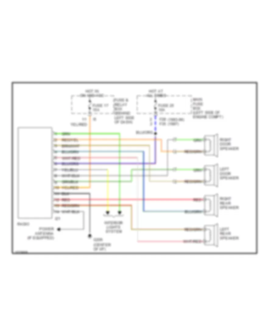
RADIO
Radio Wiring Diagrams for Subaru Impreza L 1994
List of elements for Radio Wiring Diagrams for Subaru Impreza L 1994:
- (center of i/p)
- F28 (1993-96) f35 (1997)
- Fuse & relay box (behind left side of dash)
- Fuse 17 15a
- Fuse 25 10a
- G206
- Hot at all times
- Hot in on and acc
- I21
- Interior lights system
- Left door speaker
- Left rear speaker
- Main fuse box (left side of engine compt)
- Power antenna (if equipped)
- Radio
- Red
- Right door speaker
- Right rear speaker
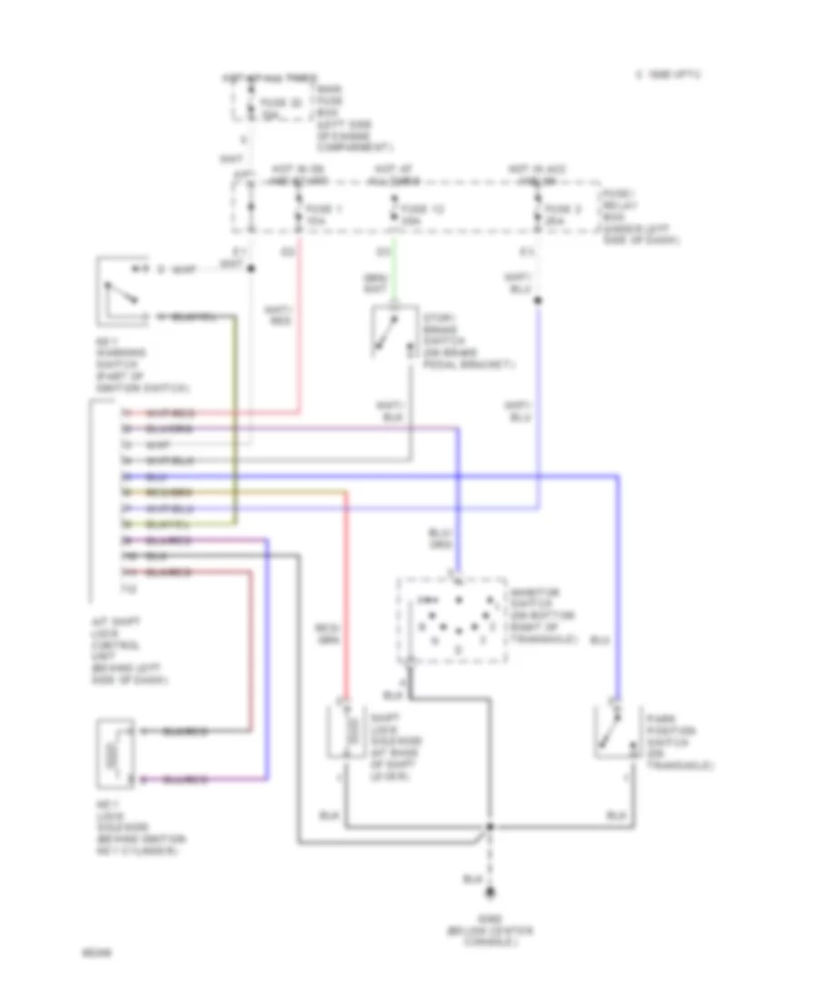
SHIFT INTERLOCKS
Shift Interlock Wiring Diagram for Subaru Impreza L 1994
List of elements for Shift Interlock Wiring Diagram for Subaru Impreza L 1994:
- A/t shift lock control unit (behind left side of dash)
- C 1995 vftc
- Fuse 1 15a
- Fuse 12 20a
- Fuse 2 20a
- Fuse 22 15a
- Fuse/ relay box (under left side of dash)
- G302 (below center console)
- Hot at all times
- Hot in acc and on
- Hot in on and start
- Inhbitor switch (on bottom right of transaxle)
- Key lock solenoid (behind ignition key cylinder)
- Key warning switch (part of ignition switch)
- Main fuse box (left side of engine comparment)
- Park position switch (on transaxle)
- Shift lock solenoid (at base of shift lever)
- Stop/ brake switch (on brake pedal bracket)
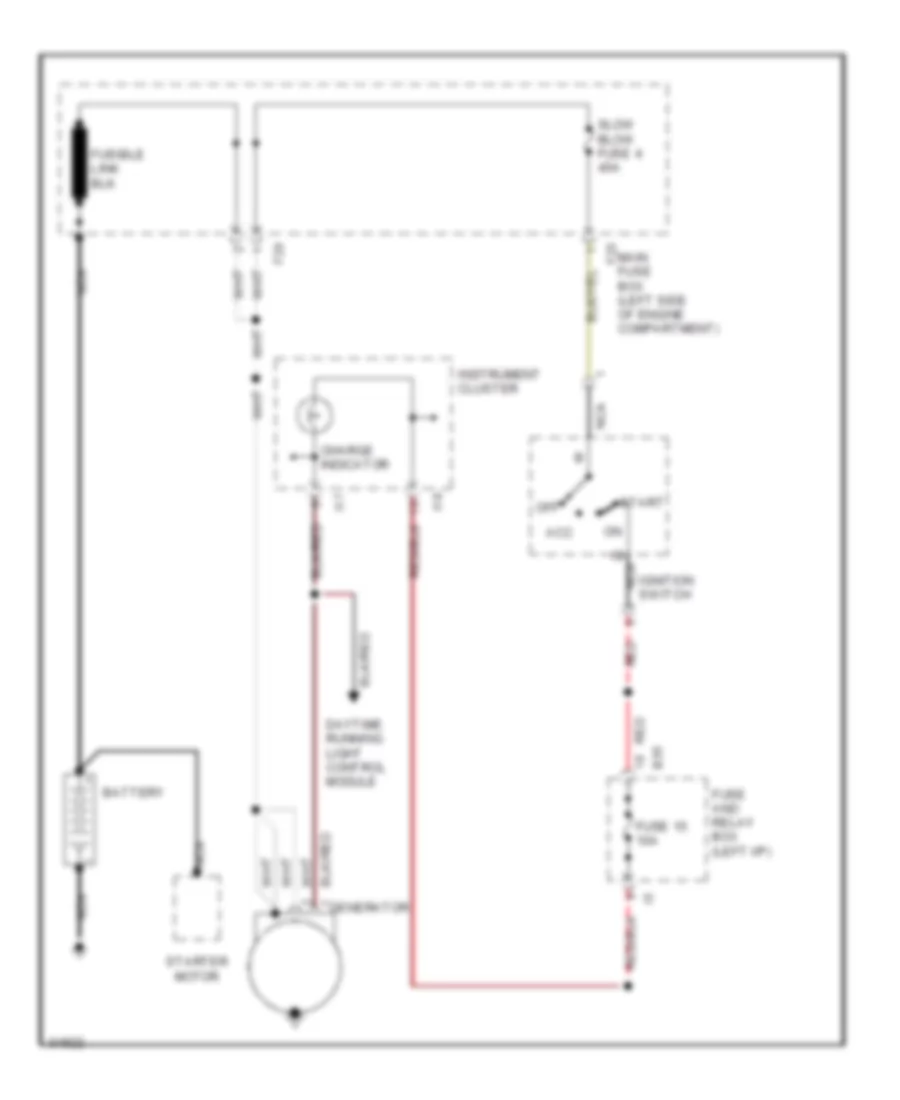
STARTING/CHARGING
Charging Wiring Diagram for Subaru Impreza L 1994
List of elements for Charging Wiring Diagram for Subaru Impreza L 1994:
- Acc
- B35
- Battery
- Charge indicator
- Daytime running light control module
- F25
- F29
- Fuse 15 10a
- Fuse and relay box (left i/p)
- Generator
- I17
- I18
- Ignition switch
- Instrument cluster
- Main fuse box (left side of engine compartment)
- Nca
- Nca b
- Off
- Red
- Slow blow fuse 4 45a
- Start
- Starter motor
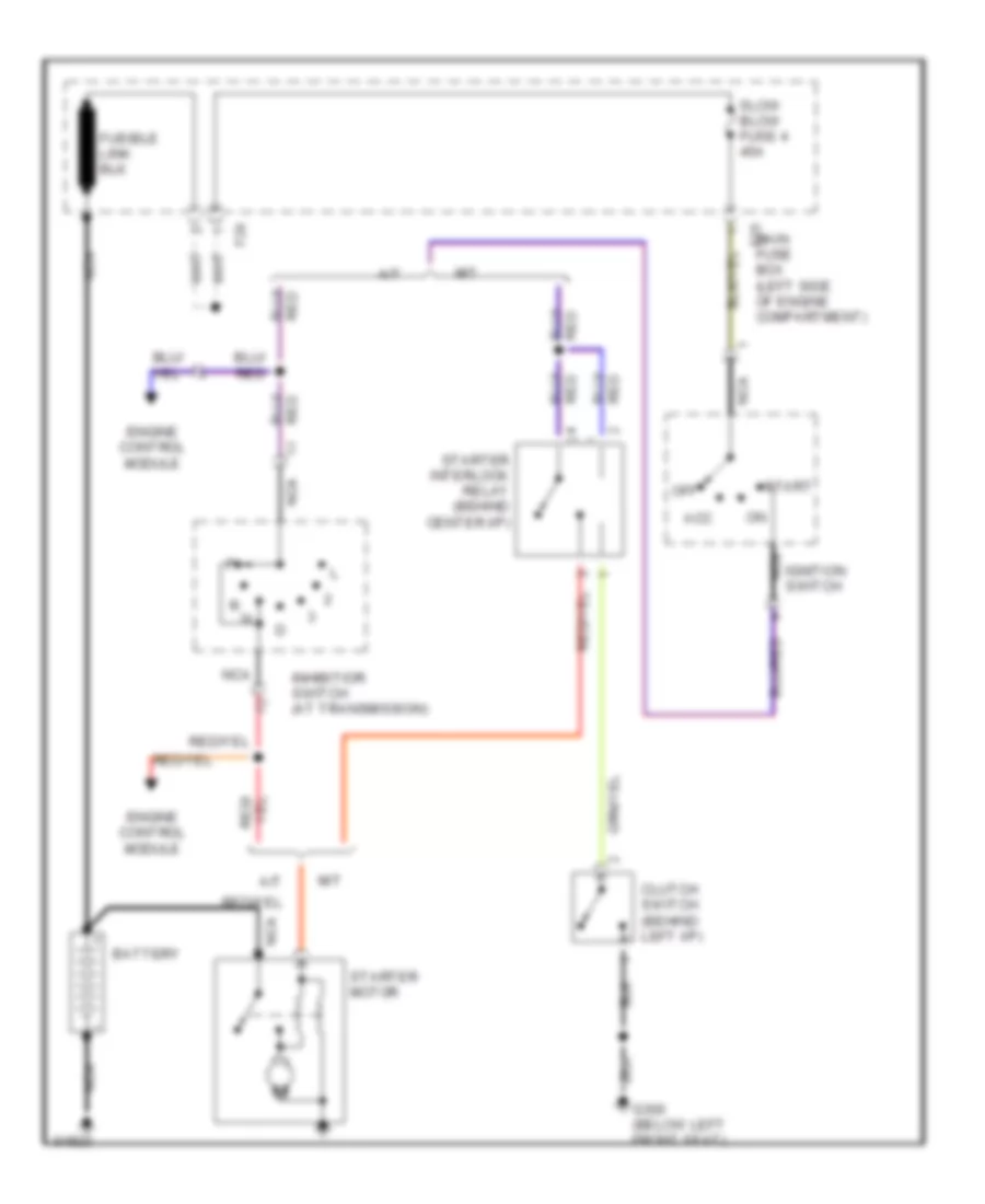
Starting Wiring Diagram for Subaru Impreza L 1994
List of elements for Starting Wiring Diagram for Subaru Impreza L 1994:
- A/t
- Acc
- Battery
- Clutch switch (behind left i/p)
- Engine control module
- F29
- Fuse box (left side of engine compartment)
- G300 (below left front seat)
- Ignition switch
- Inhibitior switch (at transmission)
- M/t
- Main f25
- Nca
- Off
- Slow blow fuse 4 45a
- Start
- Starter interlock relay (behind center i/p)
- Starter motor
SUPPLEMENTAL RESTRAINTS
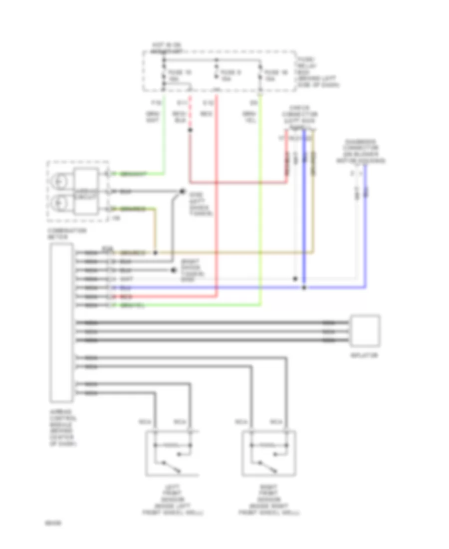
Supplemental Restraint Wiring Diagram for Subaru Impreza L 1994
List of elements for Supplemental Restraint Wiring Diagram for Subaru Impreza L 1994:
- (right shock tower) g103
- Airbag circuit
- Airbag control module (behind center of dash)
- B39
- Check connector (left kick panel)
- Combination meter
- Diagnosis connector (on blower motor housing)
- E11
- E12
- F10
- Fuse 15 10a
- Fuse 16 15a
- Fuse 8 15a
- Fuse/ relay box (behind left side of dash)
- G102 (left shock tower)
- Hot in on and start
- I16
- Inflator
- Left front sensor (inside left front wheel well)
- Nca
- Red
- Right front sensor (inside right front wheel well)
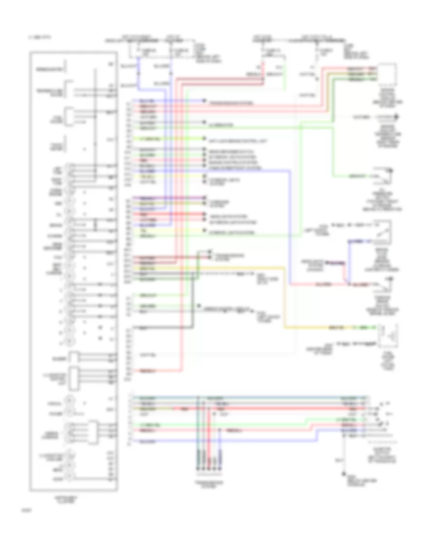
TRANSMISSION
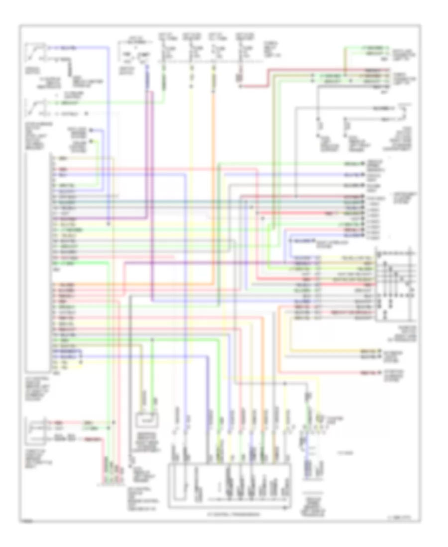
Transmission Wiring Diagram for Subaru Impreza L 1994
List of elements for Transmission Wiring Diagram for Subaru Impreza L 1994:
- (right rear of engine compartment)
- (right side of transaxle)
- * w/ awd
- 1 indic
- 1995 vftc c
- 2 indic
- 3 indic
- A/t control module (behind left i/p, right of steering column)
- Acc
- Anti-lock brakes system
- At control (transmission)
- Atf temperature sensor
- Awd solenoid
- B11
- B15
- B37
- B52
- B53
- B63
- Check connector (left i/p)
- Cruise control system
- D indic
- Data link connector (left i/p)
- Dropping resistor
- E11
- Exterior lights system
- Fuse & relay box (left i/p)
- Fuse 10a
- Fuse 15a
- Fuse 20a
- Fwd indic
- Fwd switch (w/ awd) (right side of engine compartment)
- G104 (rear of left front fender)
- G108 (left radiator support)
- G302 (below center console)
- Hot at all times
- Hot in on or start
- Ignition switch
- Inhibitor switch
- Instrument cluster system
- Lock-up solenoid
- Manual indic
- Manual switch
- Mfi control module (or) engine control unit (center of i/p)
- N indic
- Off
- P indic
- Power indic
- R indic
- Red
- Shift interlock system
- Shift solenoid 1
- Shift solenoid 3
- Solenoid 2 shift
- Solenoid line pressure
- Start
- Starting/ charging system
- Stop & brake switch (or) stop light switch (on pedal bracket)
- Throttle position sensor (on throttle body)
- Twisted pair
- Vehicle speed sensor 1 (left side of transaxle)
- Vehicle speed sensor 2
- W/ cruise control
WARNING SYSTEMS
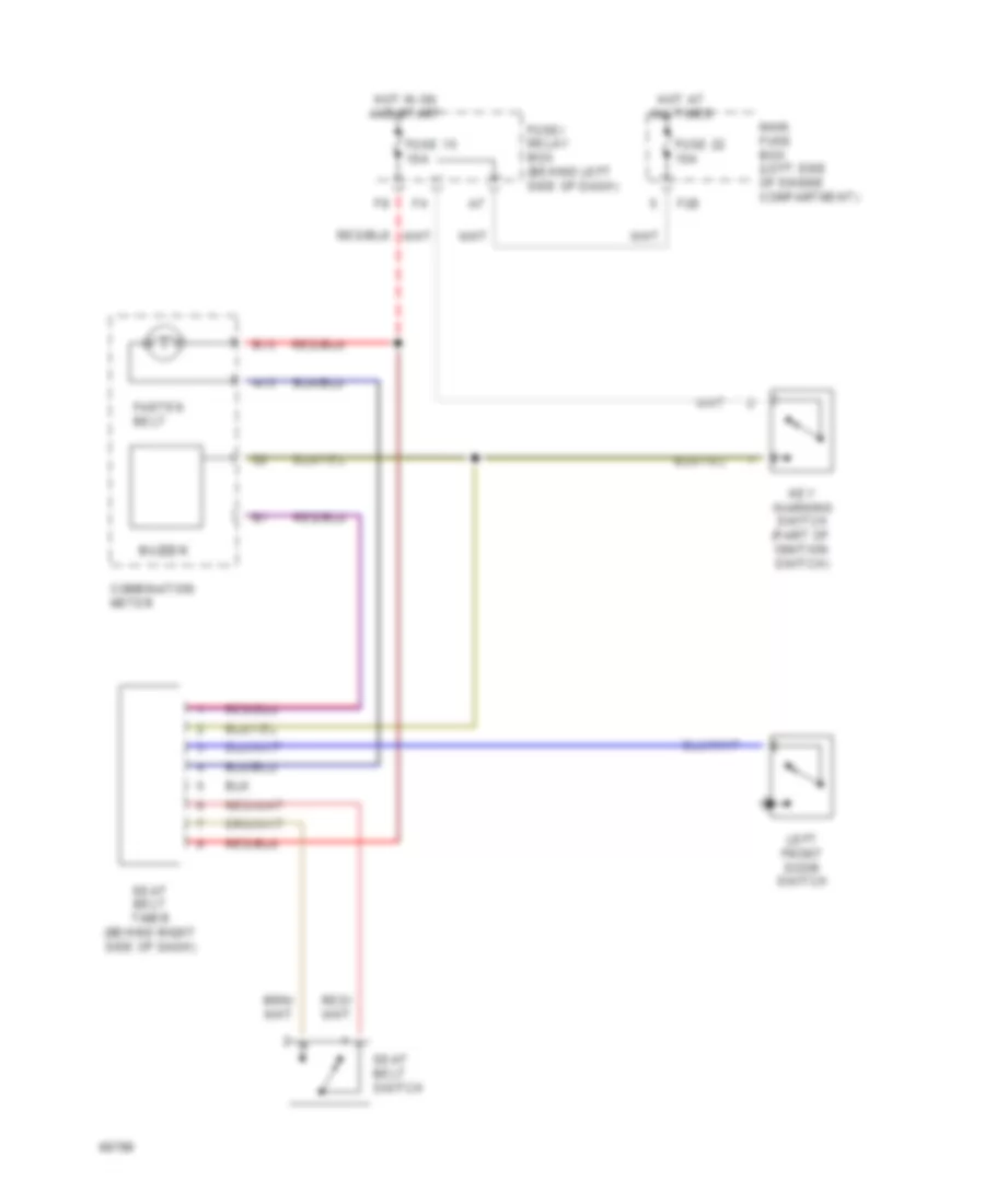
Warning System Wiring Diagrams for Subaru Impreza L 1994
List of elements for Warning System Wiring Diagrams for Subaru Impreza L 1994:
- A13
- B13
- Buzzer
- Combination meter
- F28
- Fasten belt
- Fuse 15 10a
- Fuse 22 15a
- Fuse/ relay box (behind left side of dash)
- Hot at all times
- Hot in on and start
- Key warning switch (part of ignition switch)
- Left front door switch
- Main fuse box (left side of engine compartment)
- Seat belt switch
- Seat belt timer (behind right side of dash)
WIPER/WASHER
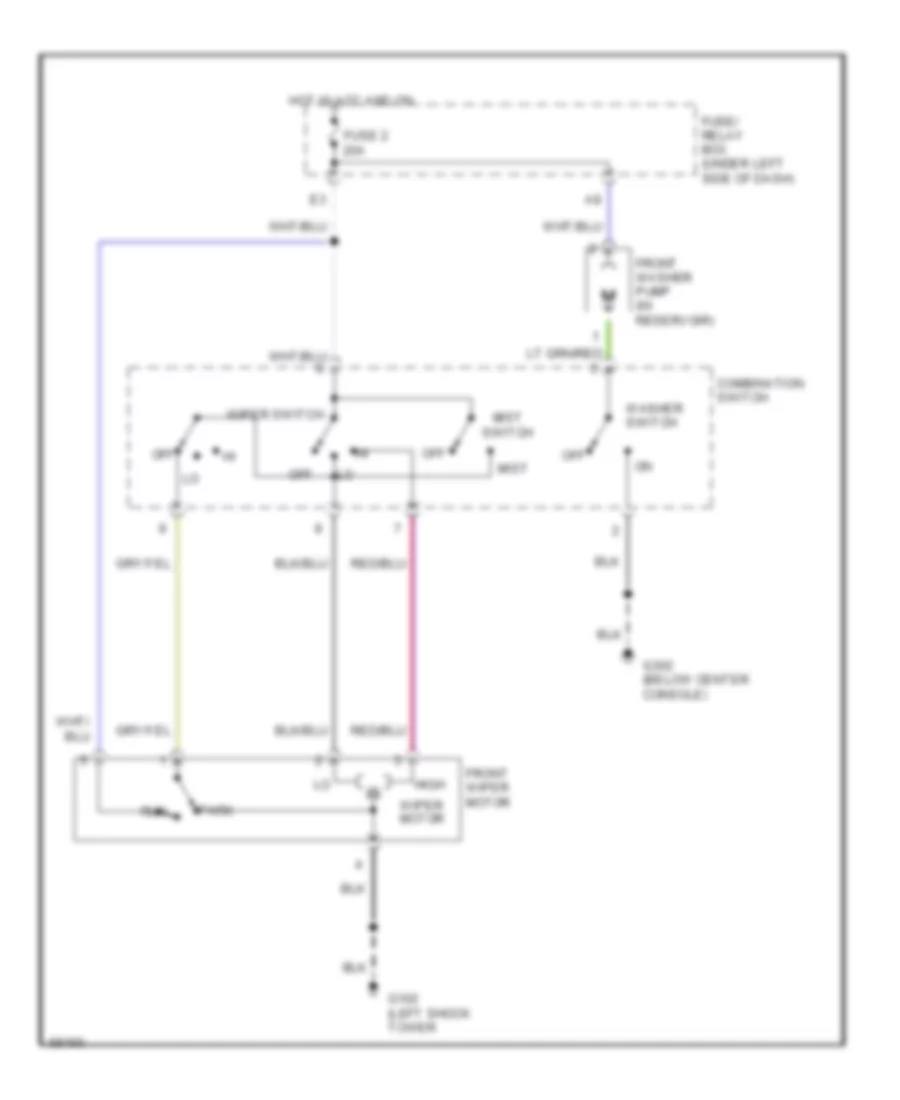
2-Speed Wiper/Washer Wiring Diagram for Subaru Impreza L 1994
List of elements for 2-Speed Wiper/Washer Wiring Diagram for Subaru Impreza L 1994:
- Combination switch
- Front washer pump (in reservoir)
- Front wiper motor
- Fuse 2 20a
- Fuse/ relay box (under left side of dash)
- G102 (left shock tower
- G302 (below center console)
- High
- Hot in acc and on
- Mist
- Mist switch
- Off
- Park
- Run
- Washer switch
- Wiper motor
- Wiper switch
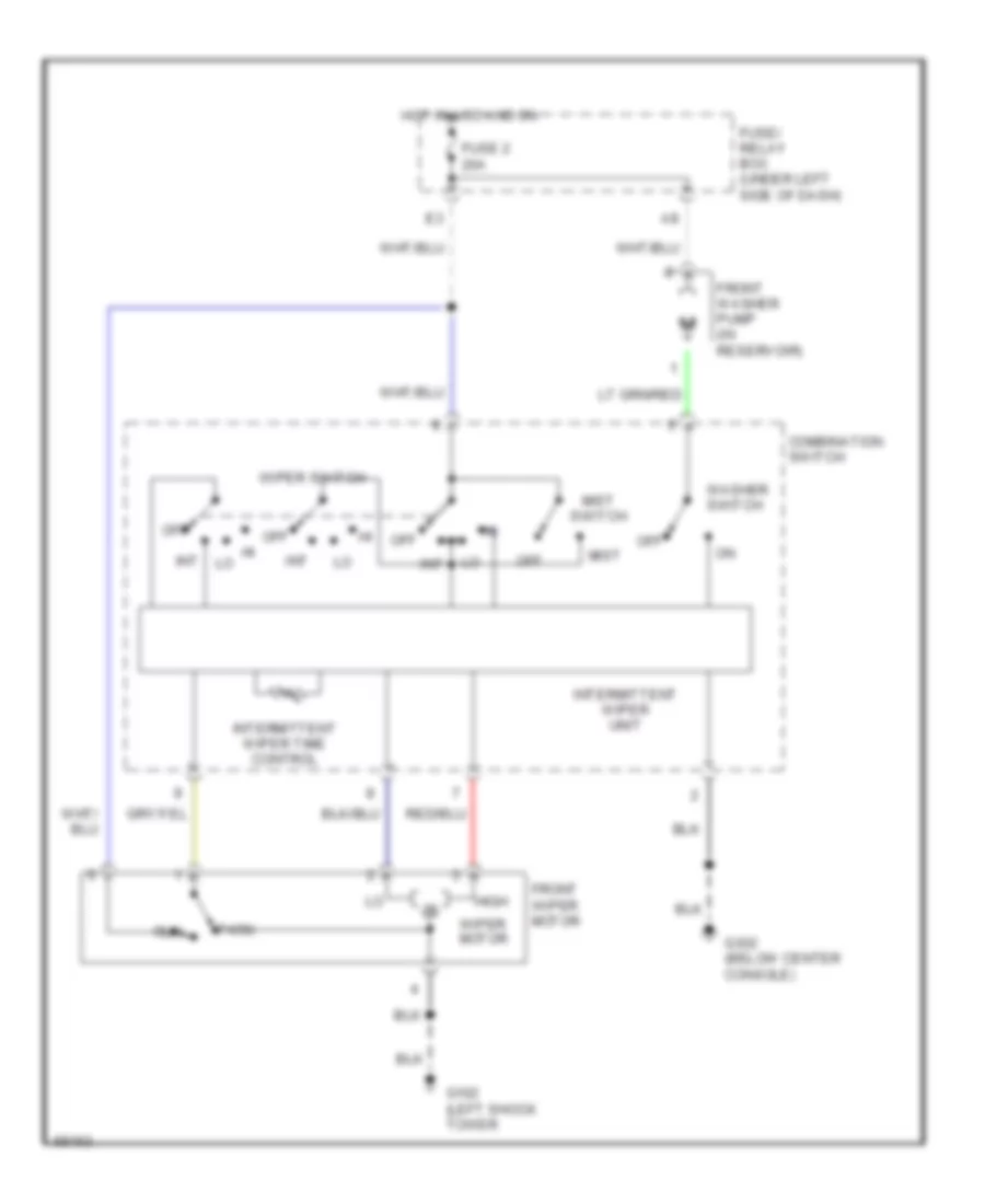
Interval Wiper/Washer Wiring Diagram for Subaru Impreza L 1994
List of elements for Interval Wiper/Washer Wiring Diagram for Subaru Impreza L 1994:
- Combination switch
- Front washer pump (in reservoir)
- Front wiper motor
- Fuse 2 20a
- Fuse/ relay box (under left side of dash)
- G102 (left shock tower
- G302 (below center console)
- High
- Hot in acc and on
- Int
- Intermittent wiper time control
- Intermittent wiper unit
- Mist
- Mist switch
- Off
- Park
- Run
- Washer switch
- Wiper motor
- Wiper switch
Rear Wiper/Washer Wiring Diagram for Subaru Impreza L 1994