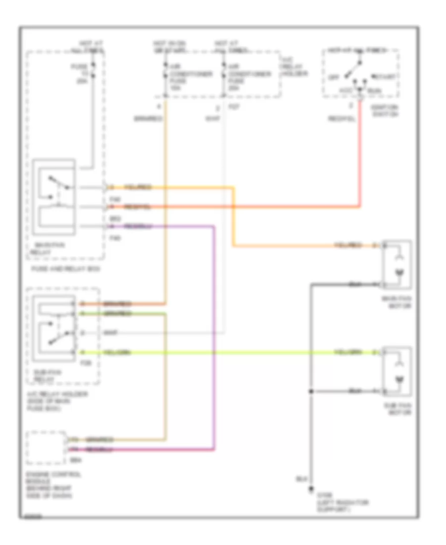
AIR CONDITIONING
A/C Wiring Diagram for Subaru Impreza L 1997

List of elements for A/C Wiring Diagram for Subaru Impreza L 1997:
- (left side of engine compartment)
- (right radiator support)
- (right side
- A/c relay holder
- A/c switch
- Acc
- Air conditioner fuse 10a
- Air conditioning cut relay (right side of firewall)
- Air conditioning relay (in a/c relay holder)
- Blower motor
- Blower motor relay (behind left side of dash)
- Blower motor resistor (behind right side of dash)
- Clutch
- Compressor
- Diode (a/c) (behind left side of dash)
- E11
- Engine control module (under passenger floorboard)
- Evaporation thermoswitch (behind right side of dash)
- F27
- Fan switch
- Fuse 10a
- Fuse 20 15a
- Fuse 20a
- Fuse 21 15a
- Fuse and relay box
- G109
- G201
- Hot at all times
- Hot in on or start
- I17
- I30
- Ignition switch
- Interior lights system
- Main fan motor
- Main fan relay
- Mode control panel
- Nca
- Of dash)
- Off
- Pressure switch
- Run
- Start
- Sub fan motor
- Sub-fan relay (in a/c relay holder)
- Thermal protector
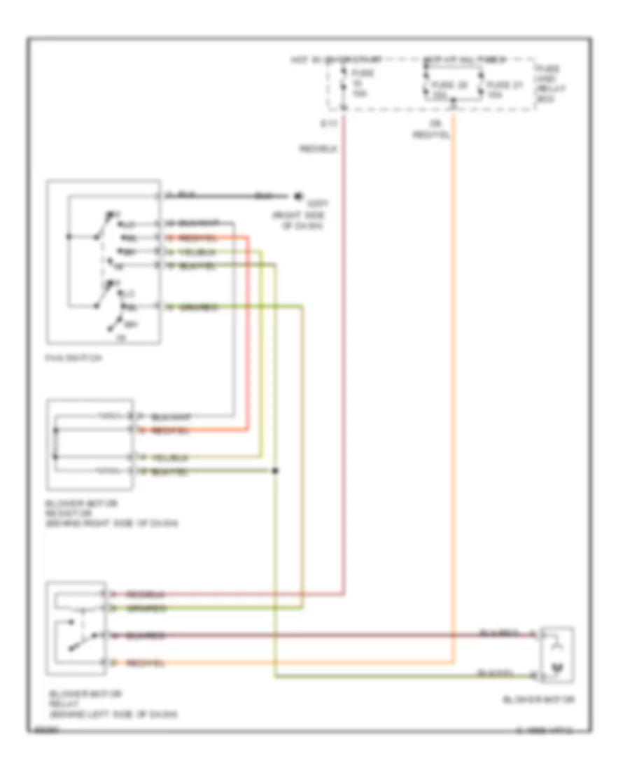
Heater Wiring Diagram for Subaru Impreza L 1997
List of elements for Heater Wiring Diagram for Subaru Impreza L 1997:
- (right side
- Blower motor
- Blower motor relay (behind left side of dash)
- Blower motor resistor (behind right side of dash)
- C 1995 vftc
- E11
- Fan switch
- Fuse 10a
- Fuse 20 15a
- Fuse 21 15a
- Fuse and relay box
- G201
- Hot at all times
- Hot in on or start
- Of dash)
- Off
ANTI-LOCK BRAKES
Anti-lock Brake Wiring Diagrams (1 of 2) for Subaru Impreza L 1997
List of elements for Anti-lock Brake Wiring Diagrams (1 of 2) for Subaru Impreza L 1997:
- Abs control module (left side of engine compartment)
- Abs diagnosis connector (behind left side of dash)
- B51
- B56
- Check connector (behind left side of dash)
- Data link connector (under left side of dash)
- F34
- F42
- F49
- Fuse & relay box (left side of dash)
- Fuse 12 20a
- Fuse 15 10a
- Fuse 18
- Fuse 19 20a
- G102 (left strut tower)
- Hot at all times
- Hot in run or start
- Left front wheel sensor
- Left rear wheel sensor
- Main fuse box (left side of engine compartment)
- Nca
- Obd ii service connector (below left side of dash)
- Pnk
- Red
- Right front wheel sensor
- Right rear wheel sensor
- Sbf-6 fuse 45a
- Shield joint connector (left side of engine compartment)
- Stoplight switch (top of brake pedal bracket)
- Transmission control module (behind left side of dash)
Anti-lock Brake Wiring Diagrams (2 of 2) for Subaru Impreza L 1997
List of elements for Anti-lock Brake Wiring Diagrams (2 of 2) for Subaru Impreza L 1997:
- Abs control module (left side of engine compartment)
- Abs g sensor (left rear of engine compartment)
- Abs hydraulic module (right front of engine compartment)
- Abs ind
- Abs pump motor
- Abs1
- Abs2
- F49
- G201 (right side of dash)
- I10
- I12
- Instrument cluster
- Left front solenoids
- Left rear solenoids
- Motor relay
- Nca
- Pnk
- Red
- Relay box (right front of engine compt)
- Right front solenoids
- Right rear solenoids
- Valve relay
COMPUTER DATA LINES
Computer Data Lines for Subaru Impreza L 1997
List of elements for Computer Data Lines for Subaru Impreza L 1997:
- (behind dash, right of steeering column)
- Abs check connector
- Abs control module
- Airbag control module
- Airbag ind
- B115
- B125
- B126
- B40
- B52
- B56
- B75
- B76
- B78
- B79
- B81
- B82
- B84
- B94
- C12
- C13
- Check connector (behind left side of dash)
- Combination meter
- Cruise control module (behind left side of dash)
- Data link connector (behind dash, near steering column)
- Diagnosis connector
- Diagnosis terminal
- E11
- Engine control module (behind right side of dash)
- F37
- F49
- Fuse & relay box (behind left side of dash)
- Fuse 15 10a
- Fuse sbf2 30a
- G201 (right side of dash)
- Hot at all times
- Hot in on or start
- I13
- Main fuse box (left side of engine compt)
- Main relay (behind left side of dash)
- Nca
- Neutral position switch (m/t) (left side of transmission)
- Obd ii service connector (below left side of dash)
- Test mode connector (behind dash, right of steering column)
- Test mode connector (right kick panel)
- Transmission control module (behind left side of dash)
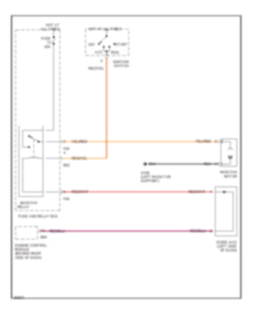
COOLING FAN
Cooling Fan Wiring Diagram, with A/C for Subaru Impreza L 1997
List of elements for Cooling Fan Wiring Diagram, with A/C for Subaru Impreza L 1997:
- A/c relay holder
- A/c relay holder (side of main fuse box)
- Acc
- Air conditioner fuse 10a
- Air conditioner fuse 20a
- B52
- B84
- Engine control module (behind right side of dash)
- F27
- F28
- F40
- Fuse 20a
- Fuse and relay box
- G108 (left radiator support)
- Hot at all times
- Hot in on or start
- Ignition switch
- Main fan
- Main fan motor
- Off
- Relay
- Relay
- Run
- Start
- Sub fan motor
- Sub-fan
Cooling Fan Wiring Diagram, without A/C for Subaru Impreza L 1997
List of elements for Cooling Fan Wiring Diagram, without A/C for Subaru Impreza L 1997:
- Acc
- B52
- B84
- Diode (a/c) (left side of dash)
- Engine control module (behind right side of dash)
- F40
- Fuse 20a
- Fuse and relay box
- G108 (left radiator support)
- Hot at all times
- Ignition switch
- Main fan
- Main fan motor
- Off
- Relay
- Run
- Start
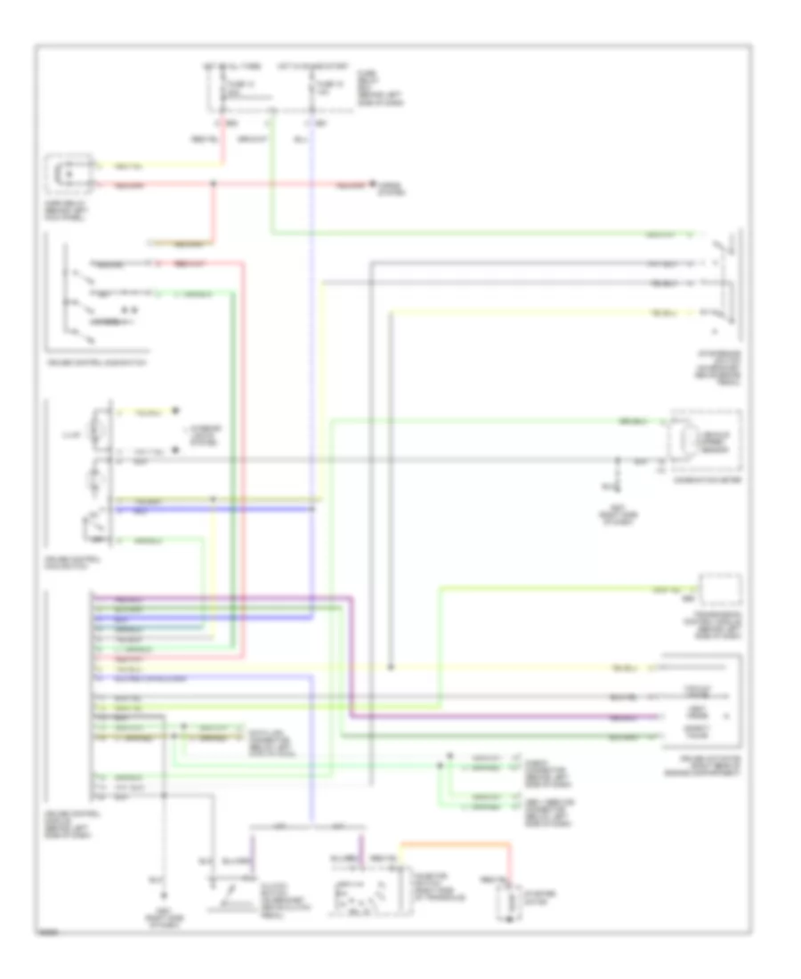
CRUISE CONTROL
Cruise Control Wiring Diagram for Subaru Impreza L 1997
List of elements for Cruise Control Wiring Diagram for Subaru Impreza L 1997:
- A/t
- B51
- B52
- B56
- Cancel
- Check connector (behind left side of dash)
- Clutch switch (on bracket above clutch pedal)
- Combination meter
- Cruise actuator (right rear of engine compartment)
- Cruise control main switch
- Cruise control module (behind left side of dash)
- Cruise control sub switch
- Data link connector (below left side of dash)
- Fuse 12 20a
- Fuse 18 10a
- Fuse/ relay box (behind left side of dash)
- G201 (right side of dash)
- Horn relay (behind left kick panel)
- Horns system
- Hot at all times
- Hot in on and start
- I12
- Illum
- Inhibitor switch (right side of transaxle)
- Interior lights system
- M/t
- Obd ii service connector (below left side of dash)
- Off
- Resume
- Safety valve
- Set
- Starter motor
- Stop/brake switch (on bracket above brake pedal)
- Transmission control module (behind left side of dash)
- Vacuum valve
- Vehicle speed sensor
- Vent valve
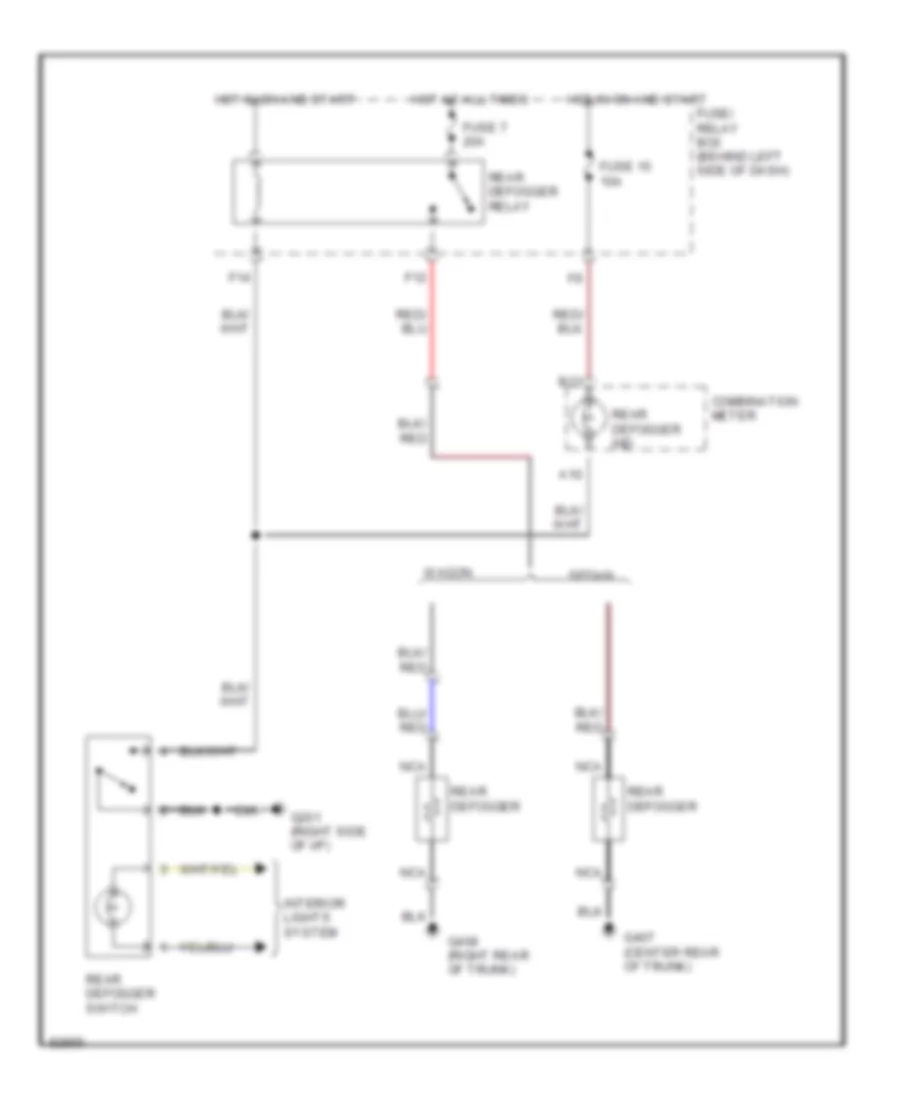
DEFOGGERS
Defogger Wiring Diagram for Subaru Impreza L 1997
List of elements for Defogger Wiring Diagram for Subaru Impreza L 1997:
- A10
- B13
- Combination meter
- F12
- F14
- Fuse 15 10a
- Fuse 7 20a
- Fuse/ relay box (behind left side of dash)
- G201 (right side of i/p)
- G407 (center rear of trunk)
- G408 (right rear of trunk)
- Hot at all times
- Hot in on and start
- Interior lights system
- Nca
- Rear defogger
- Rear defogger ind
- Rear defogger relay
- Rear defogger switch
- Sedan
- Wagon
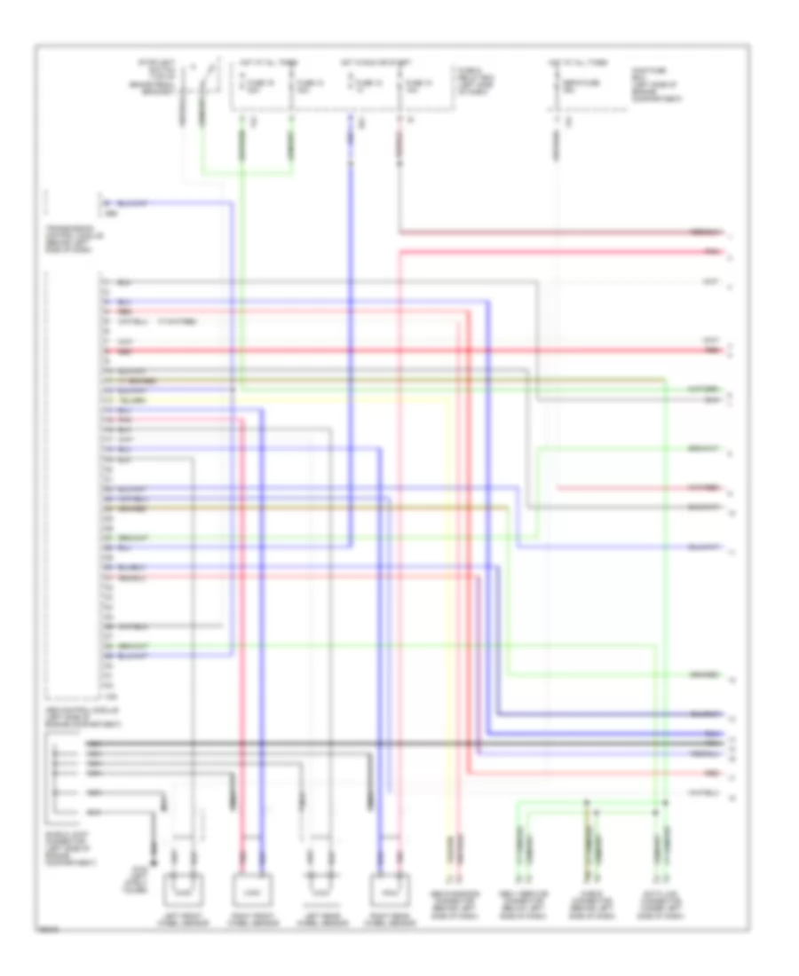
ENGINE PERFORMANCE
1.8L
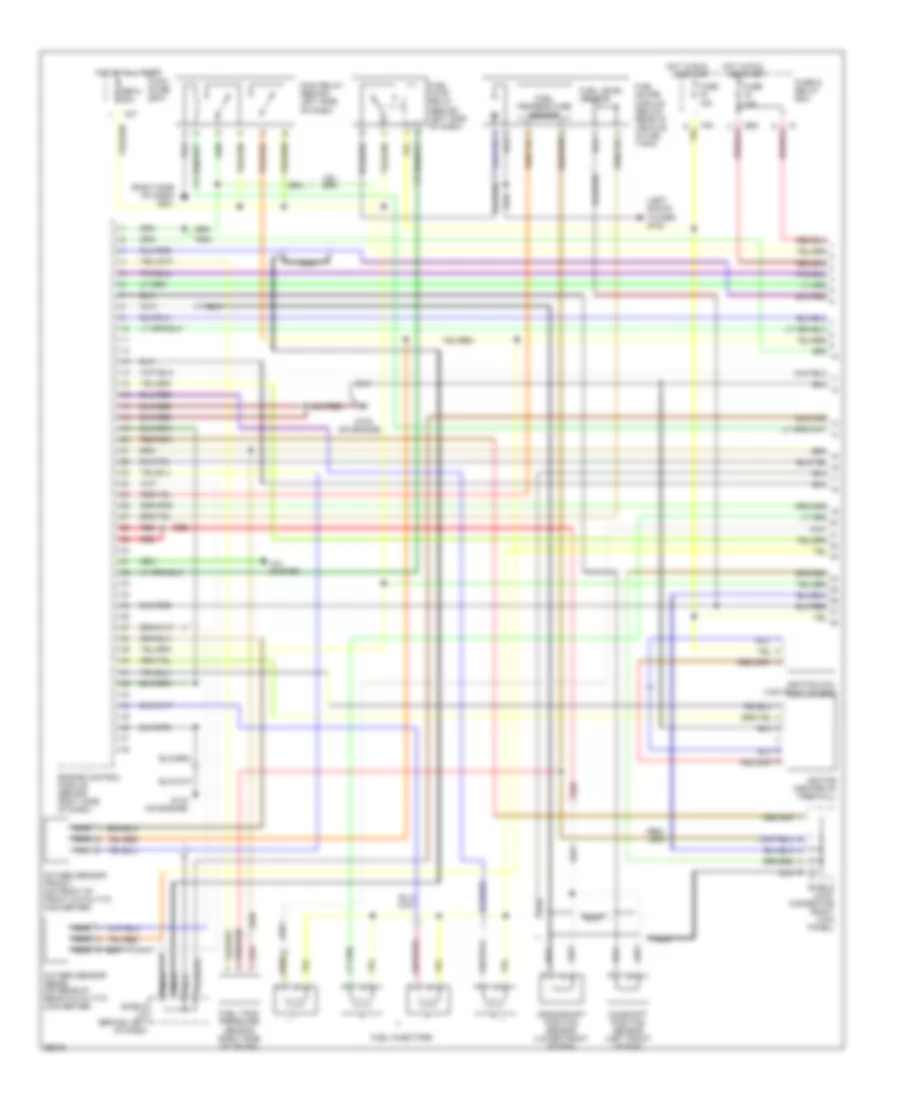
1.8L, Engine Performance Wiring Diagrams (1 of 2) for Subaru Impreza L 1997
List of elements for 1.8L, Engine Performance Wiring Diagrams (1 of 2) for Subaru Impreza L 1997:
- (left shock tower) g102
- (on engine)
- (right side of dash) g201
- A/c system
- B52
- Camshaft position sensor (left front of eng)
- Crankshaft position sensor (lower front of eng)
- Engine control module (behind right side of dash)
- F37
- F40
- Fuel gauge module (below rear of vehicle, in fuel tank)
- Fuel injectors
- Fuel level sensor
- Fuel pump relay (behind left side of dash)
- Fuel tank pressure sensor (right side of trunk)
- Fuel temperature sensor
- Fuse & relay box
- Fuse 10a
- Fuse 15a
- G133
- G133 (on engine)
- Hot at all times
- Hot in run
- Ignition coil (top front of eng)
- Ignitor (center of firewall)
- Main fuse box
- Main relay (behind left side of dash)
- Nca
- Or start
- Oxygen sensor (front) (on front of front catalytic converter)
- Oxygen sensor (rear) (on rear of rear catalytic converter)
- Red
- Sbf-2 30a
- Shield j/c (brhind left of dash)
- Shield joint connector (right kick panel)
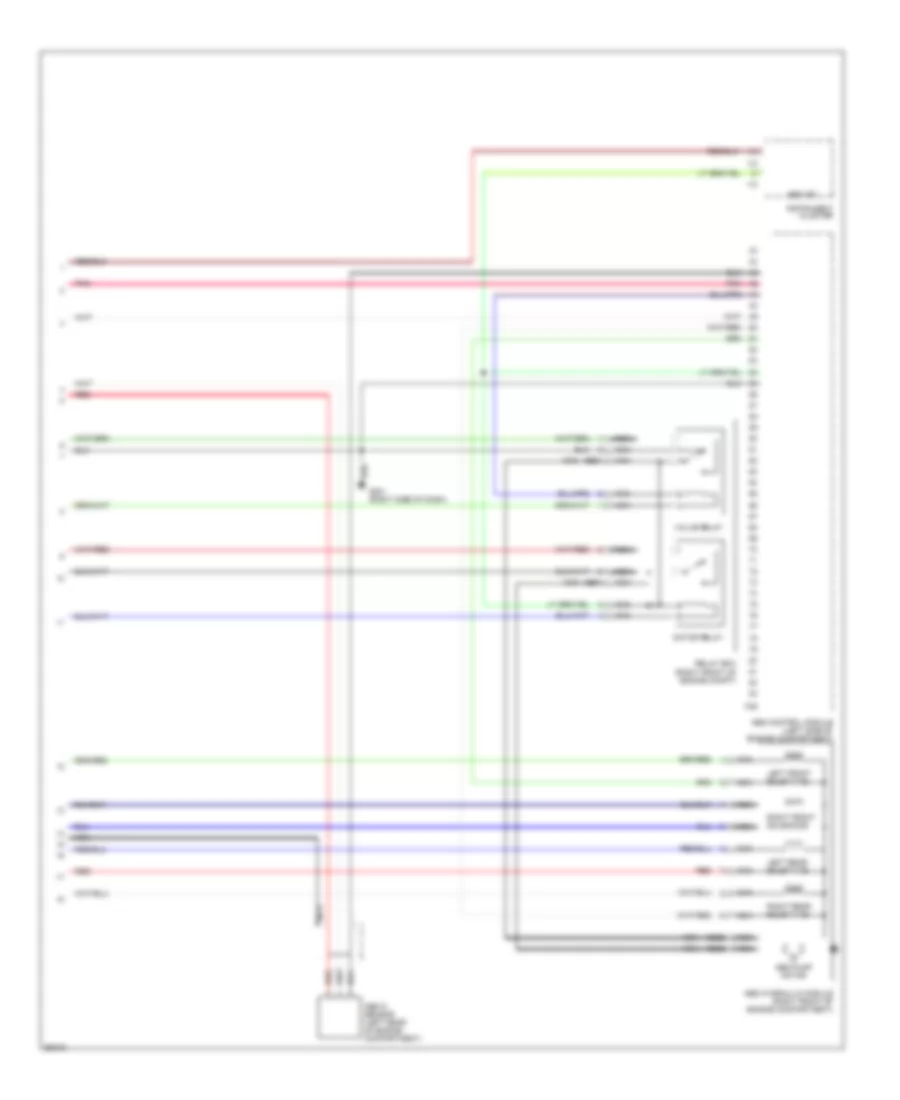
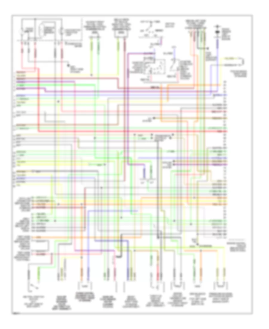
1.8L, Engine Performance Wiring Diagrams (2 of 2) for Subaru Impreza L 1997
List of elements for 1.8L, Engine Performance Wiring Diagrams (2 of 2) for Subaru Impreza L 1997:
- (behind dash, right of steering column)
- (behind left side of dash, taped to harness) check connector
- (below rear of vehicle, near fuel tank) vent control solenoid valve
- (on air (on air cleaner cleaner housing)
- (on engine)
- (on right front of fuel tank) pressure control solenoid valve
- (right side of engine compartment)
- (right side of engine compt)
- (top left side of eng, at egr valve)
- A/c system
- A/t
- Acc
- Boost sensor
- Combination meter
- Cooling fan system
- Data link connector
- Egr solenoid (a/t)
- Engine control module (behind right side of dash)
- Engine coolant temperature sensor (top right front of engine)
- Ficd solenoid (right side of engine)
- G108 (left radiator support)
- G133
- G201 (right side of dash)
- Hot at all times
- I10
- I12
- Idle air idle air control control solenoid solenoid valve valve (on throttle (on throttle body assembly) body assembly)
- Ignition switch
- Inhibitor switch (on right side of transaxle)
- Knock sensor (left side of engine)
- M/t
- Malfunction indicator lamp
- Mass air mass air flow sensor flow sensor
- Nca
- Neutral position switch (m/t) (on left side of eng compt)
- Obd-ii service connector (below left side of dash)
- Off
- Pressure sources switching solenoid
- Purge control purge control solenoid valve solenoid valve (top right front (top right front of engine) of engine)
- Red
- Start
- Starter interlock relay (behind dash, right of steering column)
- Tacho- meter
- Test mode connector (behind dash, right of steering column)
- Test mode connector (brhind right kick panel)
- Throttle position sensor (on throttle body assembly)
- Transmission controls system
- Vehicle speed sensor
2.2L
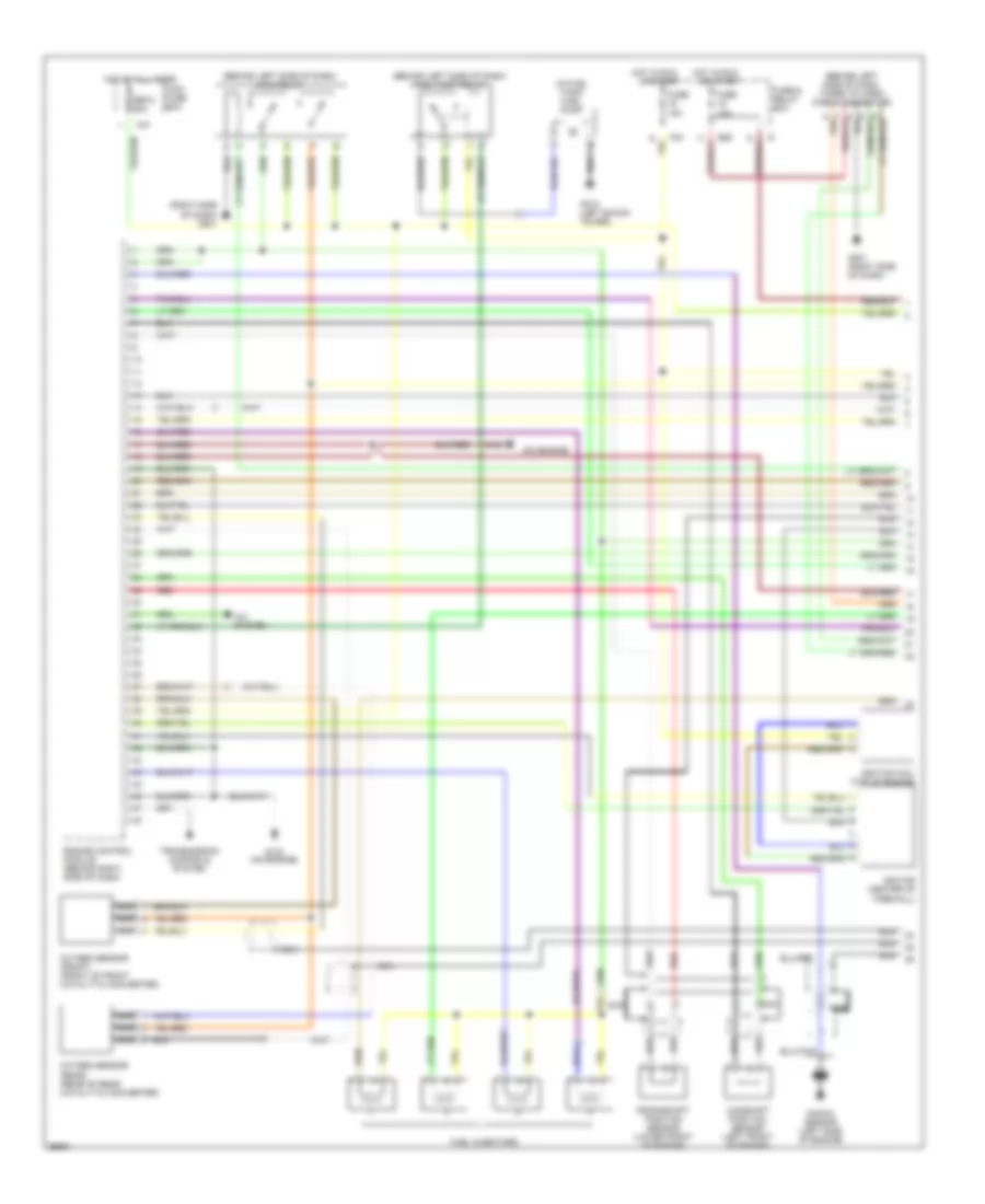
2.2L, Engine Performance Wiring Diagrams (1 of 2) for Subaru Impreza L 1997
List of elements for 2.2L, Engine Performance Wiring Diagrams (1 of 2) for Subaru Impreza L 1997:
- (behind left side of dash) fuel pump relay
- (behind left side of dash) main relay
- (behind left side of dash, taped to harn) check connector
- (in fuel tank) fuel pump
- (on engine)
- (right side of dash) g201
- A/c system
- B52
- Camshaft position sensor (left front of engine)
- Crankshaft position sensor (lower front of engine)
- Engine control module (behind right side of dash)
- F37
- F40
- Fuel injectors
- Fuse & relay box
- Fuse 10a
- Fuse 15a
- G102 (left shock tower)
- G133
- G133 (on engine)
- G201 (right side of dash)
- Hot at all times
- Hot in run
- Ignition coil (top of engine)
- Ignitor (center of firewall)
- Knock sensor (left side of engine)
- Main fuse box
- Nca
- Or start
- Oxygen sensor (front) (front of front catalytic converter)
- Oxygen sensor (rear) (rear of rear catalytic converter)
- Red
- Sbf-2 30a
- Transmission controls system
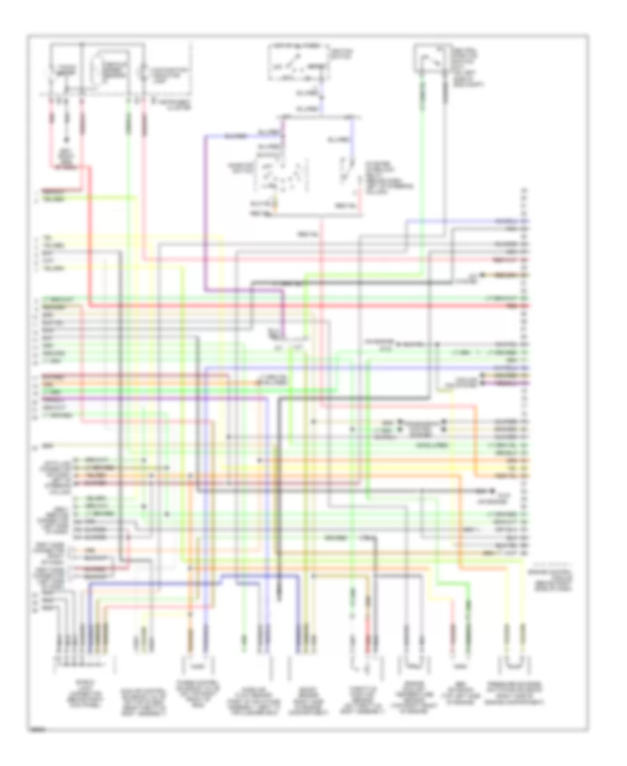
2.2L, Engine Performance Wiring Diagrams (2 of 2) for Subaru Impreza L 1997
List of elements for 2.2L, Engine Performance Wiring Diagrams (2 of 2) for Subaru Impreza L 1997:
- (on engine)
- (part of air intake assembly, neat to air cleaner box)
- (right side of engine compartment)
- (top left side of engine)
- A/c system
- A/t
- Acc
- Boost sensor
- Cooling fan system
- Data link connector (on dash,
- Egr solenoid
- Engine control module (behind right (side of dash)
- Engine coolant temperature sensor (top right front of engine)
- G133
- G201 (right side of dash)
- Hot at all times
- I10
- I12
- Idle air control solenoid valve (on top of eng, near throttle body assembly)
- Ignition switch
- Inhibitor switch
- Instrument cluster
- Left of steering column)
- M/t
- Malfunction indicator lamp
- Mass air flow sensor
- Nca
- Neutral position switch (m/t) (on left side of eng compt)
- Obd-ii service connector (left side of dash)
- Off
- Pressure sources switching solenoid
- Purge control solenoid valve (on top right front of eng)
- Red
- Shield joint connector (behind right kick panel)
- Start
- Starter interlock relay (behind dash, left of steering column)
- Tacho- meter
- Test mode connector (left side of dash)
- Test mode connector (right of dash)
- Throttle position sensor (on throttle body assembly)
- Transmission control system
- Vehicle speed sensor
EXTERIOR LIGHTS
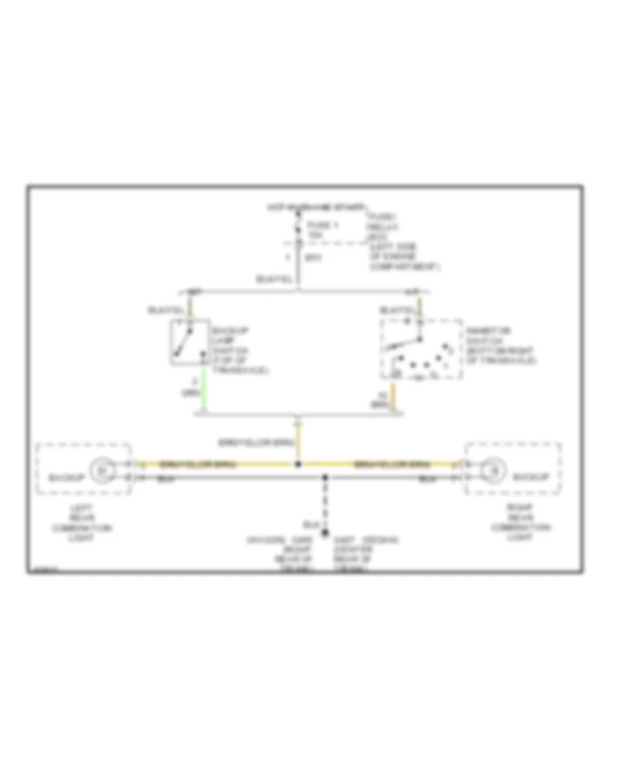
Back-up Lamps Wiring Diagram for Subaru Impreza L 1997
List of elements for Back-up Lamps Wiring Diagram for Subaru Impreza L 1997:
- (sedan)
- (wagon)
- A/t
- B51
- Backup
- Backup lamp switch (top of transaxle)
- Fuse 1 15a
- Fuse/ relay box (left side of engine compartment)
- G405 (right rear of trunk)
- G407 (center rear of trunk)
- Hot in on and start
- Inhibitor switch (bottom right of transaxle)
- Left rear combination light
- M/t
- Right rear combination light
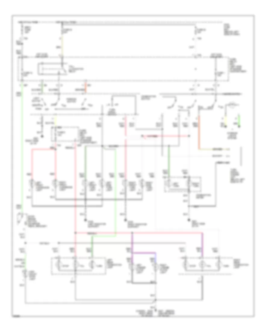
Exterior Lamps Wiring Diagram for Subaru Impreza L 1997
List of elements for Exterior Lamps Wiring Diagram for Subaru Impreza L 1997:
- (or
- (right side
- (sedan)
- (wagon)
- A11
- B15
- B35
- B51
- B52
- B57
- Combination meter
- Combination switch
- F35
- F36
- F40
- F42
- Fuse 1 15a
- Fuse 12 20a
- Fuse 22 15a
- Fuse 23 20a
- Fuse 5 10a
- Fuse/ relay box (left side of engine compartment)
- G108 (left radiator support)
- G109 (right radiator support)
- G201
- G201 (right side of i/p)
- G405 (right rear of trunk)
- G407 (center rear of trunk)
- Hazard switch
- Head
- High mount stop light
- Hot at all times
- Hot in on and start
- Interior lights system
- Left front clearance light
- Left front turn light
- Left license plate light
- Left rear combination lamp
- Left side turn light
- Left turn
- Light switch
- Main fuse box (behind left side of dash)
- Of i/p)
- Off
- Park
- Parking switch
- Red
- Right front clearance light
- Right front turn light
- Right license plate light
- Right rear combination lamp
- Right side turn light
- Right turn
- Sbf-3 fuse 45a
- Stop
- Stop/ brake switch (on brake pedal bracket)
- Tail
- Tail/ illumination relay
- Turn
- Turn signal switch
- Turn signal/ hazard unit (below left side of i/p)
GROUND DISTRIBUTION
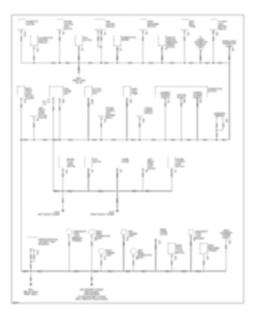
Ground Distribution Wiring Diagram (1 of 2) for Subaru Impreza L 1997
List of elements for Ground Distribution Wiring Diagram (1 of 2) for Subaru Impreza L 1997:
- 1.8l
- 2.2l
- A/t shift lock control module
- Abs control module
- B106
- B119
- B16
- B177
- B32
- B42
- B43
- B44
- B57
- B69
- B70
- B71
- B81
- B92
- Brake fluid level switch
- Cigarette lighter
- Clutch switch (m/t)
- Combination meter
- Combination switch
- Cruise control main switch
- D39
- D43
- D46
- D48
- Diagnosis terminal
- Dimmer & passing switch
- Door lock timer
- F48
- F49
- Fan switch
- Fuel gauge unit
- Fwd switch
- G102 (left shock tower)
- G103 (right shock tower)
- G201 (right side of i/p)
- G301 (below right front seat)
- G407 (except wagon) g405 (wagon) (center rear of trunk-except wagon, right rear of trunk-wagon)
- High-mount stop light (except wagon)
- High-mount stop light (wagon)
- I12
- I15
- I18
- I19
- Illumination control module
- Left front door lock switch
- Left front door switch (coupe)
- Left license light
- Left rear combination light
- Lighting switch
- Parking position and shift lock solenoid
- Power window and sunroof relay
- Power window main switch
- R12
- R19
- R26
- R28
- R33
- R58
- R76
- R77
- Rear defogger (wagon)
- Rear defogger switch
- Rear gate latch switch
- Rear wiper motor
- Remote control rearview mirror switch
- Right front door switch (coupe)
- Right license light
- Right rear combination light
- Seat belt timer
- Shield joint connector (a.b.s.)
- To check connector (diagram 2 of 2)
- Turn & hazard module
- Wiper & washer switch
- Wiper motor
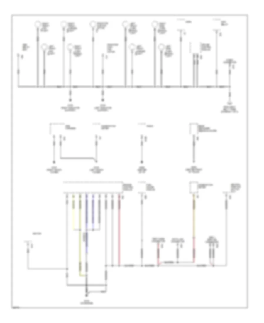
Ground Distribution Wiring Diagram (2 of 2) for Subaru Impreza L 1997
List of elements for Ground Distribution Wiring Diagram (2 of 2) for Subaru Impreza L 1997:
- Abs relay box
- B120
- B13
- B25
- B31
- B40
- B47
- B76
- B78
- B79
- B84
- B94
- Check connector
- Combination meter
- Cruise control module
- Data link connector
- Engine control module
- F16
- F17
- F19
- F21
- F50
- F51
- F52
- F53
- F54
- From seat belt timer (diagram 1 of 2)
- Fuel gauge module
- G102 (left shock tower)
- G103 (right shock tower)
- G108 (left radiator support)
- G109 (right radiator support)
- G133 (on engine)
- G206 (center of i/p)
- G408 (center front of trunk)
- Horn
- I10
- I13
- Ignitor
- Left front fog light
- Left front marker light
- Left front turn signal light
- Left side turn signal light
- Main relay
- Nca
- Neutral position switch (m/t)
- Obd ii service connector
- R58
- R65
- Radiator main fan motor
- Radiator sub fan motor
- Radio
- Rear defogger (sedan & coupe)
- Right front fog light
- Right front marker light
- Right front turn signal light
- Right side turn signal light
- Srs harness
- Test mode connector
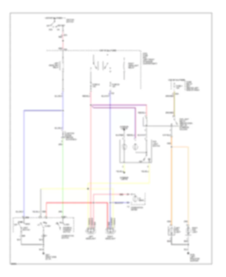
HEADLIGHTS
Headlight Wiring Diagram for Subaru Impreza L 1997
List of elements for Headlight Wiring Diagram for Subaru Impreza L 1997:
- Acc
- B48
- B69
- B71
- B72 red
- Combination meter
- Combination switch
- Dimmer & passing switch
- Flash
- Fog light relay (behind dash, left of steering column)
- Fog light switch
- Fuse 24 15a
- Fuse 26 15a
- Fuse 4 15a
- Fuse/ relay box (behind left side of dash)
- G109 (left radiator support
- G201 (right side of i/p)
- Head
- Hi beam
- Hot at all times
- I12
- Ignition switch
- Interior lights
- Left fog light
- Left headlight
- Left headlight relay
- Light switch
- Lighting diode (behind glove box)
- Main fuse box (left front of engine compartment)
- Off
- Park
- Red
- Red f39
- Right fog light
- Right headlight
- Right headlight relay
- Start
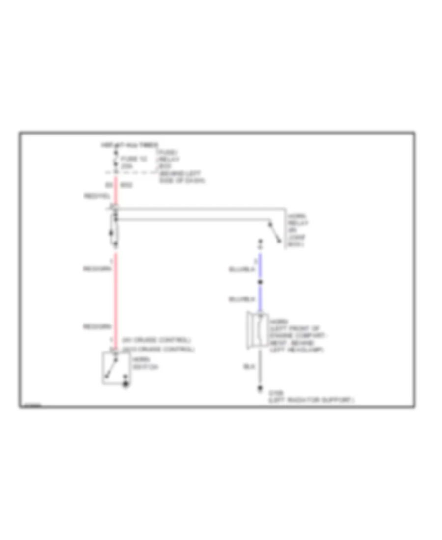
HORN
Horn Wiring Diagram for Subaru Impreza L 1997
List of elements for Horn Wiring Diagram for Subaru Impreza L 1997:
- (w/ cruise control)
- (w/o cruise control)
- B52
- Fuse 12 20a
- Fuse/ relay box (behind left side of dash)
- G108 (left radiator support)
- Horn (left front of engine compart- ment, behind left headlamp)
- Horn relay (in joint box)
- Horn switch
- Hot at all times
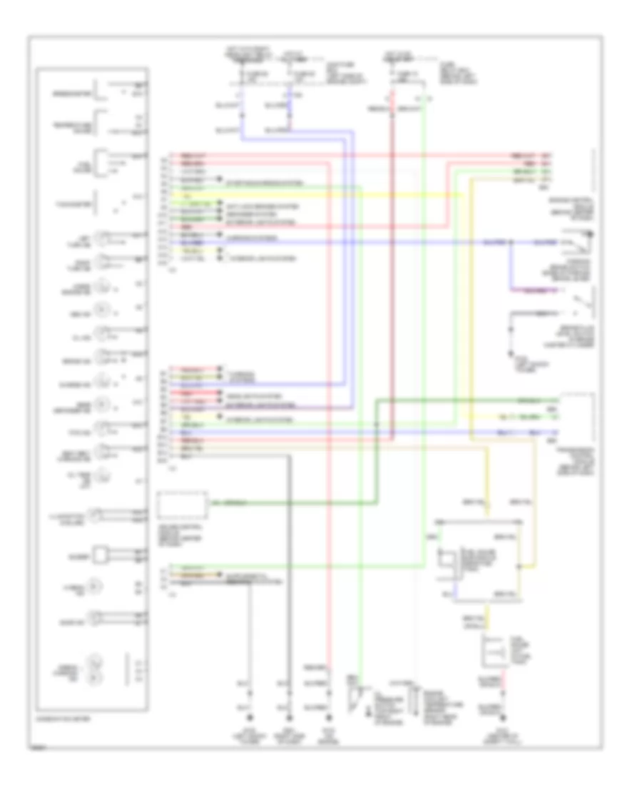
INSTRUMENT CLUSTER
Instrument Cluster Wiring Diagram for Subaru Impreza L 1997
List of elements for Instrument Cluster Wiring Diagram for Subaru Impreza L 1997:
- 1.8l
- 2.2l
- A10
- A11
- A12
- A13
- A14
- A15
- A16
- Abs ind
- Airbag warning ind
- Anti-lock brakes system
- B12
- B13
- B14
- B15
- B55
- B56
- B84
- Brake fluid level switch (in brake master cylinder)
- Brake ind
- Buzzer
- Charge ind
- Check engine ind
- Combination meter
- Cruise control module (behind center of dash)
- Defogger system
- Door ind
- Engine control module (behind center of dash)
- Engine coolant temperature sensor (right rear of engine)
- Exterior lights system
- F35
- Fuel gauge
- Fuel gauge sub module (near fuel tank)
- Fuel gauge unit (in fuel tank)
- Fuse 15 15a
- Fuse 25 10a
- Fuse 26 15a
- Fuse/ relay box (behind left side of dash)
- Fwd ind
- G102 (left shock tower)
- G121 (center of safety wall)
- G133 (on engine)
- G201 (right side of dash)
- Headlights system
- Hi beam ind
- Hot at all times
- Hot in on and start
- Hot with right headlight relay energized
- I10
- I12
- I13
- Illumination (5 bulbs)
- Interior lights system
- Left turn ind
- Main fuse box (left side of engine compt)
- Oil ind
- Oil pressure switch (top right front of engine)
- Oil temp ind (a/t)
- Parking brake switch (base of parking brake lever)
- Rear defogger ind
- Red
- Right turn ind
- Seat belt warning ind
- Speedometer
- Starting/charging system
- Tachometer
- Temperature gauge
- Transmission control module (behind left side of dash)
- Warning systems
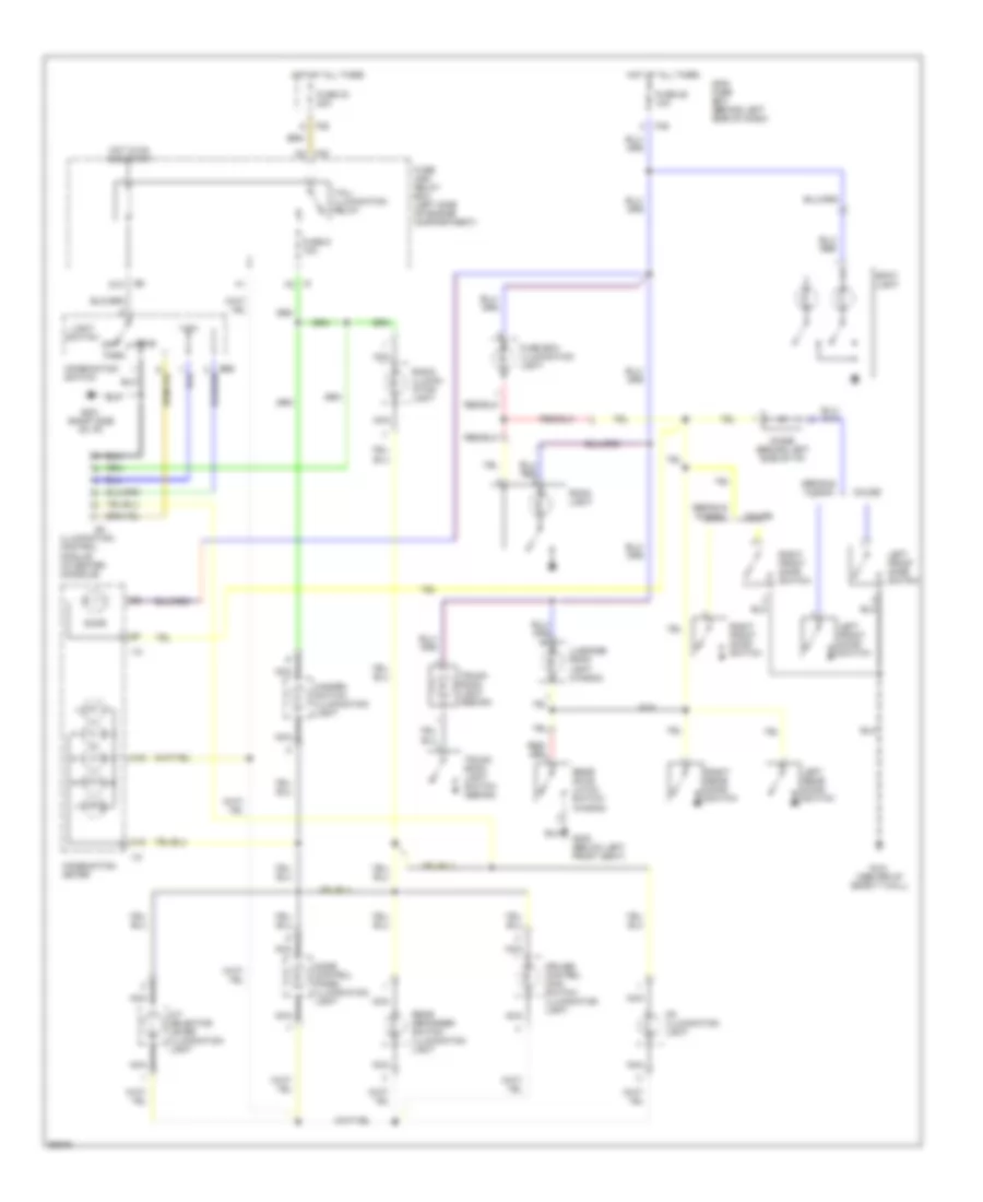
INTERIOR LIGHTS
Interior Light Wiring Diagram for Subaru Impreza L 1997
List of elements for Interior Light Wiring Diagram for Subaru Impreza L 1997:
- A/t selector lever illumination light
- A15
- A16
- B69
- Cd illumination light
- Combination meter
- Combination switch
- Coupe
- Cruise control main switch illumination light
- D10
- Diode (behind left side of i/p)
- Door
- F35
- F40
- Fuse 23 20a
- Fuse 25 10a
- Fuse 9 10a
- Fuse and relay box (left side of engine compartment)
- Fuse box illumination light
- G121 (center of safety wall)
- G201 (right side of i/p)
- G300 (below left front seat)
- Hazard switch illumination light
- Head
- Hot at all times
- Hot in on and start
- I10
- I12
- I20
- Illumination control module (in center console)
- Left front door switch
- Left rear door switch
- Light switch
- Luggage room light (wagon)
- Main fuse box (behind left side of dash)
- Mode control panel illumination light
- Nca
- Off
- Park
- Radio illumin- ation light
- Rear defogger switch illumination light
- Rear gate latch switch (wagon)
- Right front door switch
- Right rear door switch
- Room light
- Sedan & wagon
- Spot light
- Tail/ illumination relay
- Trunk room light (sedan)
- Trunk room light switch (sedan)
POWER DISTRIBUTION
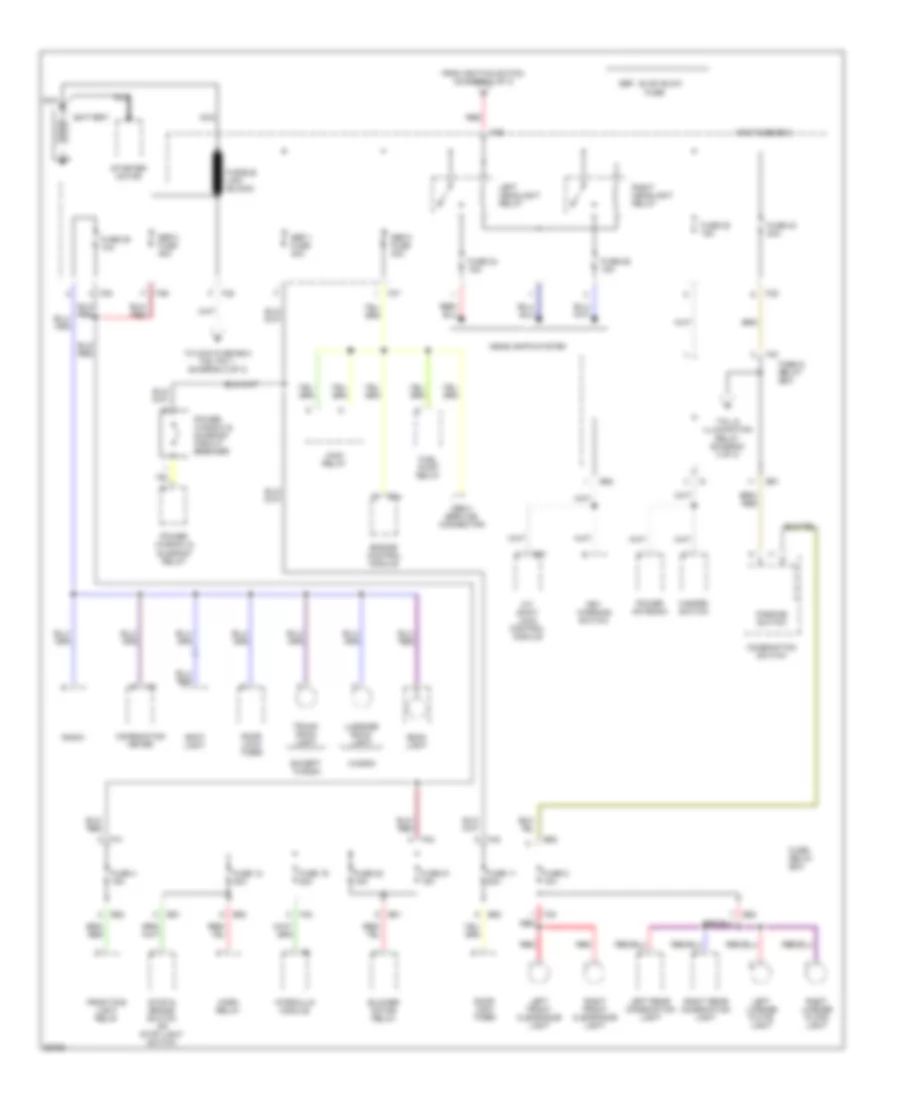
Power Distribution Wiring Diagram (1 of 3) for Subaru Impreza L 1997
List of elements for Power Distribution Wiring Diagram (1 of 3) for Subaru Impreza L 1997:
- A/t shift lock control module
- B51
- B52
- B57
- B84
- Battery
- Blower motor relay
- Combination meter
- Combination switch
- Door lock timer
- Engine control module
- Except wagon
- F35
- F36
- F37
- F38
- F39
- F40
- F41
- F42
- From ignition switch (diagram 2 of 3)
- Front fog light relay
- Fuel pump relay
- Fuse
- Fuse & relay box
- Fuse 11 20a
- Fuse 12 20a
- Fuse 19 20a
- Fuse 20 15a
- Fuse 21 15a
- Fuse 22 15a
- Fuse 23 20a
- Fuse 24 15a
- Fuse 25 10a
- Fuse 26 15a
- Fuse 4 15a
- Fuse 5 10a
- Fuse/ relay box
- Fusible link (black)
- Hazard switch
- Headlights system
- Horn relay
- Hydraulic module
- I12
- Key warning switch
- Left front clearance light
- Left headlight relay
- Left license plate light
- Left rear combination light
- Luggage room light
- Main fuse box
- Main relay
- Nca
- Obd-ii service connector
- Parking switch
- Power antenna
- Power window & sunroof circuit breaker
- Power window & sunroof relay
- Radio
- Red
- Right front clearance light
- Right headlight relay
- Right license plate light
- Right rear combination light
- Room light
- Sbf-1 fuse 30a
- Sbf-2 fuse 30a
- Sbf-3 fuse 45a
- Sbf: slow blow
- Spot light
- Starter motor
- Stop & brake switch or stop light switch
- Tail & illumination relay (diagram 3 of 3)
- To main fuse box f38, pin 1 (diagram 2 of 3)
- Trunk room light
- Wagon
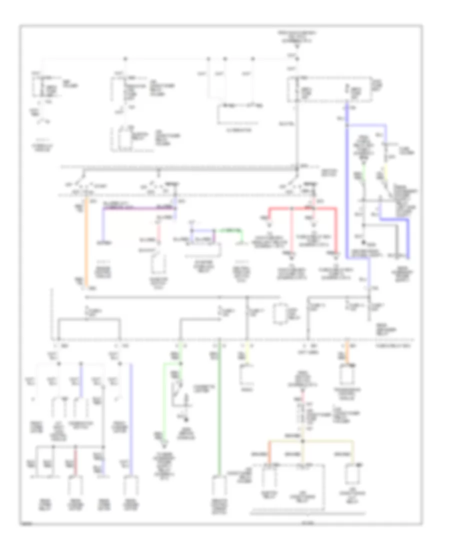
Power Distribution Wiring Diagram (2 of 3) for Subaru Impreza L 1997
List of elements for Power Distribution Wiring Diagram (2 of 3) for Subaru Impreza L 1997:
- (not used)
- 20a
- A/t
- A/t shift lock control module
- Acc
- Air conditioner fuse 10a
- Air conditioner relay holder
- Air conditioning cut relay
- Air conditioning relay
- Alternator
- B26
- B51
- B52
- B56
- B57
- B72
- B84
- Center front of pass. compt.)
- Cigarette lighter
- Combination switch
- Engine control module
- F25
- F26
- F27
- F28
- F31
- F34
- F35
- F36
- F38
- F40
- From fuse & relay box fuse 3 (diagram 2 of 3)
- From ignition switch (diagram 2 of 3)
- From main fuse box f38, pin 2 (diagram 1 of 3)
- Front washer motor
- Front wiper motor
- Fuse & relay box
- Fuse 13 20a
- Fuse 14 10a
- Fuse 17 15a
- Fuse 2 20a
- Fuse 3 15a
- Fuse 7 20a
- Fuse holder
- G206
- G206 (behind console)
- Hydraulic module
- Ignition switch
- Inhibitor switch (2.2l)
- M/t
- Main fan relay
- Main fuse box
- Neutral position switch (2.2l)
- Off
- Radiator fan fuse 20a
- Radio
- Rear defogger relay
- Rear washer motor
- Rear wiper motor
- Rear wiper relay
- Red
- Remote control mirror switch
- Sbf holder
- Sbf-4 fuse 45a
- Sbf-5 fuse 45a
- Sbf-6 fuse 45a
- Start
- Starter interlock relay
- Sub fan relay
- Sub-fan relay
- To fuse & relay box fuse 1 (diagram 3 of 3)
- To fuse & relay box fuse 18 (diagram 3 of 3)
- To main fuse box a/c fuse (10a) (diagram 2 of 3)
- To main fuse box headlight relays (diagram 1 of 3)
- Transmission control module
- W/ a/c
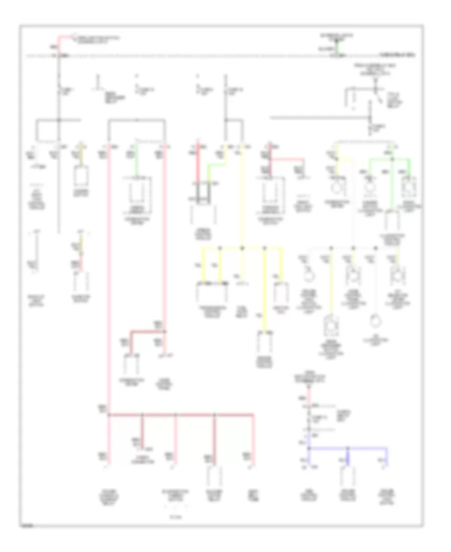
Power Distribution Wiring Diagram (3 of 3) for Subaru Impreza L 1997
List of elements for Power Distribution Wiring Diagram (3 of 3) for Subaru Impreza L 1997:
- A/t
- A/t selector lever illumination light
- A/t shift lock control module
- Abs control module
- Airbag circuit
- Airbag control module
- B31
- B51
- B52
- B54
- B55
- B57
- B79
- B84
- Back-up light switch
- Blower motor relay
- Cd illumination light
- Check connector
- Combination meter
- Combination switch
- Cruise control main switch
- Cruise control main switch illumination light
- Cruise control module
- Engine control module
- Evaporation thermo switch
- Exterior lights system
- F40
- F42
- F49
- From fuse/relay box f40, pin 2 (diagram 1 of 3)
- From ignition switch (diagram 2 of 3)
- Front fog light switch
- Fuel pump relay
- Fuse & relay box
- Fuse 1 15a
- Fuse 15 10a
- Fuse 16 15a
- Fuse 18 10a
- Fuse 8 15a
- Fuse 9 10a
- Hazard switch
- Hazard switch illumination light
- I10
- I12
- I13
- I17
- Ignition coil
- Illumination control module
- Inhibitor switch
- M/t
- Mode control panel
- Mode control panel illumination light
- Nca
- Parking switch
- Power window & sunroof relay
- Radio illumination light
- Rear defogger relay
- Rear defogger switch illumination light
- Red
- Seat belt timer
- Tail & illum- ination relay
- Transmission control module
- W/ a/c
POWER DOOR LOCKS
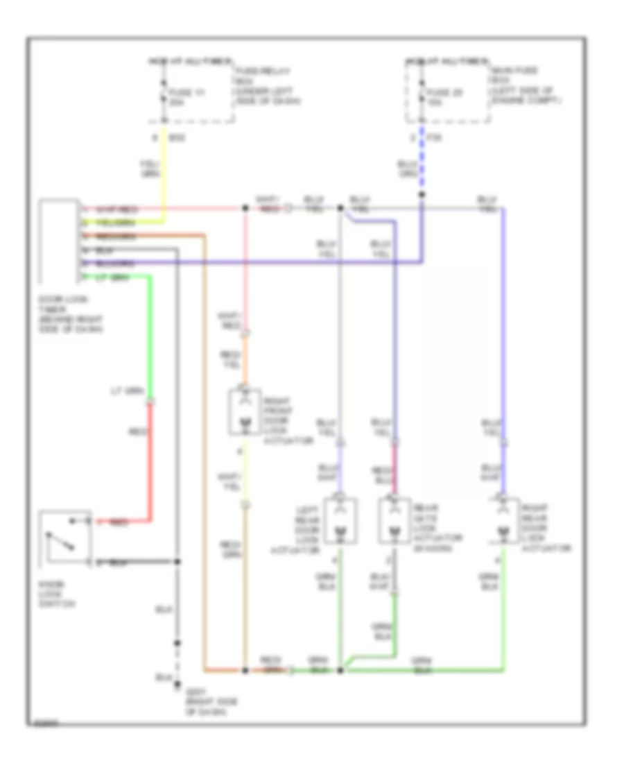
Power Door Lock Wiring Diagram for Subaru Impreza L 1997
List of elements for Power Door Lock Wiring Diagram for Subaru Impreza L 1997:
- B52
- Door lock timer (behind right side of dash)
- F35
- Fuse 11 20a
- Fuse 25 10a
- Fuse/relay box (under left side of dash)
- G201 (right side of dash)
- Hot at all times
- Knob- lock switch
- Left rear door lock actuator
- Main fuse box (left side of engine compt)
- Rear gate lock actuator (wagon)
- Red
- Right front door lock actuator
- Right rear door lock actuator
POWER MIRRORS
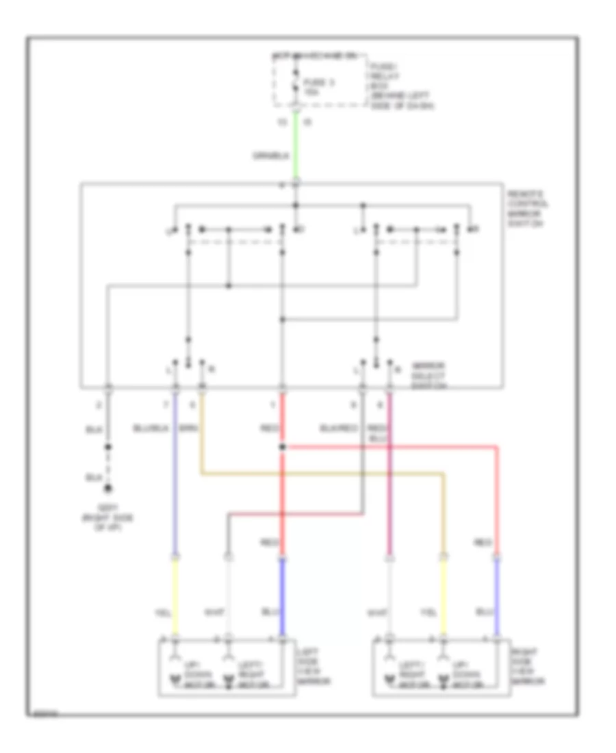
Power Mirror Wiring Diagram for Subaru Impreza L 1997
List of elements for Power Mirror Wiring Diagram for Subaru Impreza L 1997:
- Fuse 3 15a
- Fuse/ relay box (behind left side of dash)
- G201 (right side of i/p)
- Hot in acc and on
- Left side view mirror
- Left/ right m
- Mirror select switch
- Motor
- Red
- Remote control mirror switch
- Right side view mirror
- Up/ down m
POWER TOP/SUNROOF
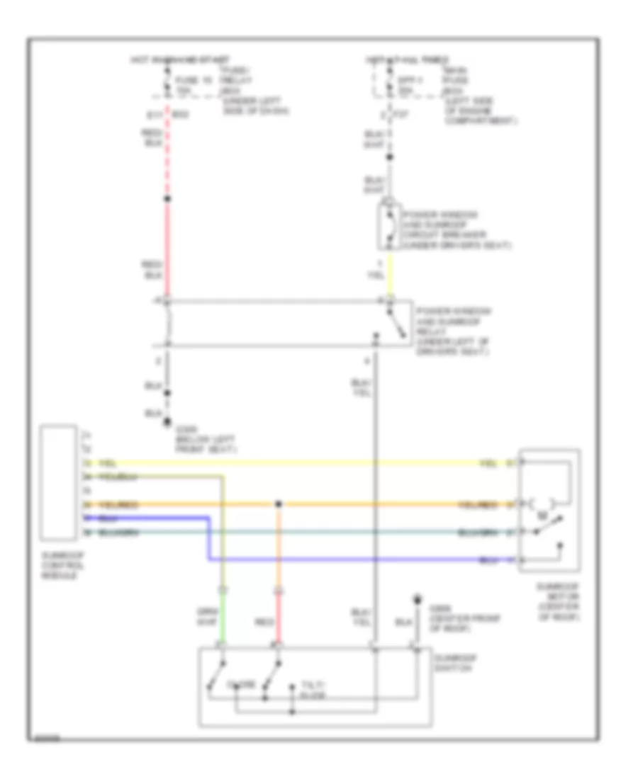
Sunroof Wiring Diagram for Subaru Impreza L 1997
List of elements for Sunroof Wiring Diagram for Subaru Impreza L 1997:
- B52 e11
- Close
- F37
- Fuse 15 10a
- Fuse/ relay box (under left side of dash)
- G300 (below left front seat)
- G908 (center front of roof)
- Hot at all times
- Hot in on and start
- Main fuse box (left side of engine compartment)
- Power window and sunroof circuit breaker (under driver's seat)
- Power window and sunroof relay (under left of driver's seat)
- Red
- Spf-1 30a
- Sunroof control module
- Sunroof motor (center of roof)
- Sunroof switch
- Tilt/ slide
POWER WINDOWS
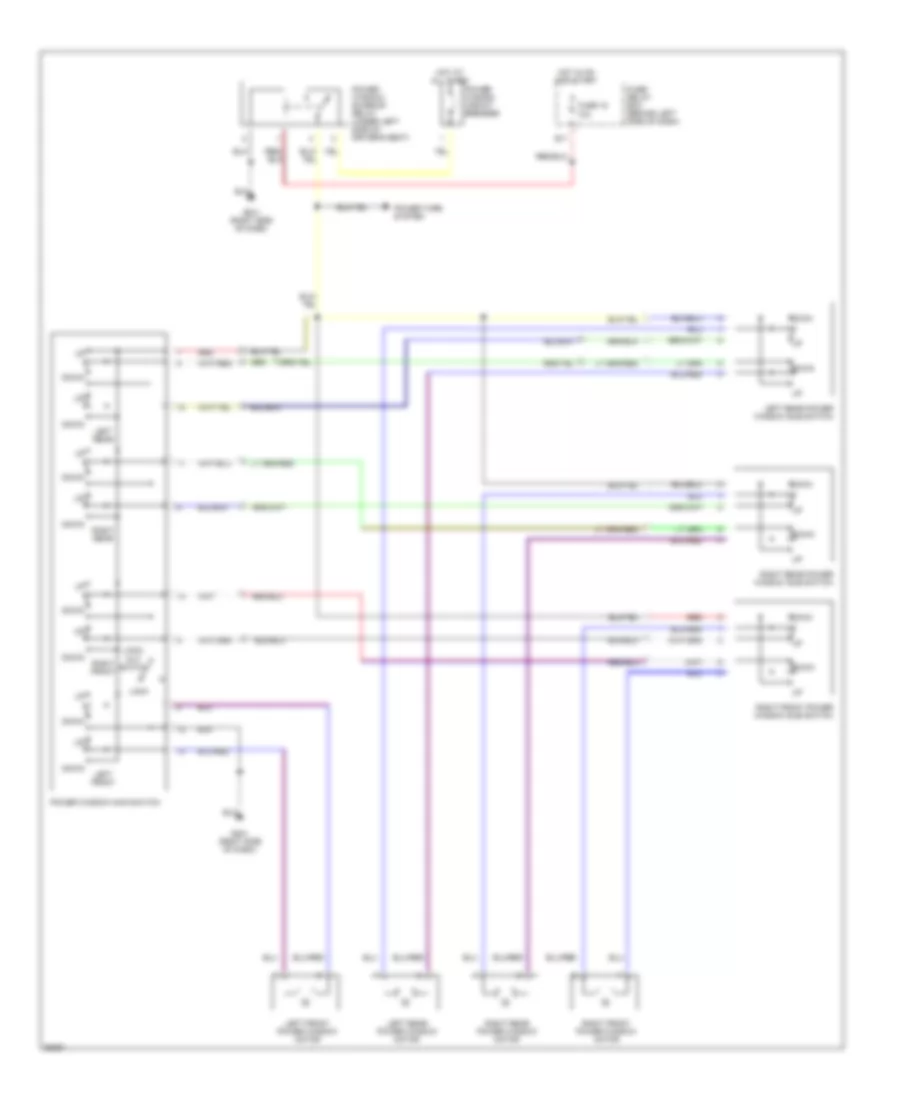
Power Window Wiring Diagram for Subaru Impreza L 1997
List of elements for Power Window Wiring Diagram for Subaru Impreza L 1997:
- Down
- E11
- Fuse 15 10a
- Fuse/ relay box (behind left side of dash)
- G201 (right side of dash)
- Hot at all times
- Hot in on and start
- Left front
- Left front power window motor
- Left rear
- Left rear power window motor
- Left rear power window sub switch
- Lock
- Lock- out switch
- Power tops system
- Power window circuit breaker
- Power window main switch
- Power window/ sunroof relay (under left side of driver's seat)
- Red
- Right front
- Right front power window motor
- Right front power window sub switch
- Right rear
- Right rear power window motor
- Right rear power window sub switch
RADIO
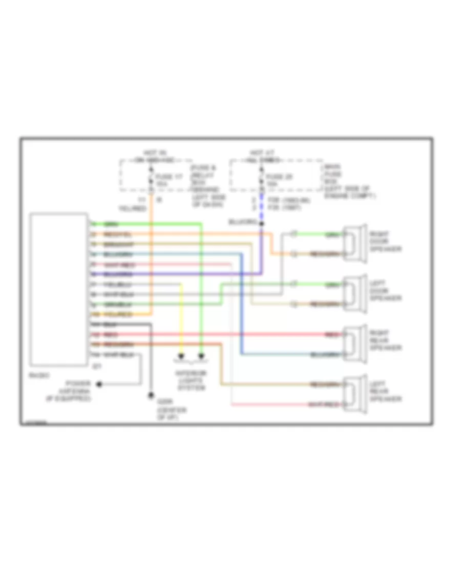
Radio Wiring Diagrams for Subaru Impreza L 1997
List of elements for Radio Wiring Diagrams for Subaru Impreza L 1997:
- (center of i/p)
- F28 (1993-96) f35 (1997)
- Fuse & relay box (behind left side of dash)
- Fuse 17 15a
- Fuse 25 10a
- G206
- Hot at all times
- Hot in on and acc
- I21
- Interior lights system
- Left door speaker
- Left rear speaker
- Main fuse box (left side of engine compt)
- Power antenna (if equipped)
- Radio
- Red
- Right door speaker
- Right rear speaker
SHIFT INTERLOCKS
Shift Interlock Wiring Diagram for Subaru Impreza L 1997
List of elements for Shift Interlock Wiring Diagram for Subaru Impreza L 1997:
- (w/o cruise control) (w/ cruise control)
- A/t shift lock control unit (behind left side of dash)
- B51 d3
- B52 e3
- B57
- F35
- F40 a7
- Fuse 1 15a
- Fuse 12 20a
- Fuse 2 20a
- Fuse 22 15a
- Fuse/ relay box (under left side of dash)
- G102 (left shock tower)
- G121 (center of safety wall)
- Hot at all times
- Hot in acc and on
- Hot in on and start
- Inhbitor switch (on right side of trans- mission)
- Key lock solenoid (behind ignition key cylinder)
- Key warning switch (part of ignition switch)
- Main fuse box (left side of engine compt)
- Park position switch (at base of shift lever)
- Shift lock solenoid (at base of shift lever)
- Stop/ brake switch (on brake pedal bracket)
STARTING/CHARGING
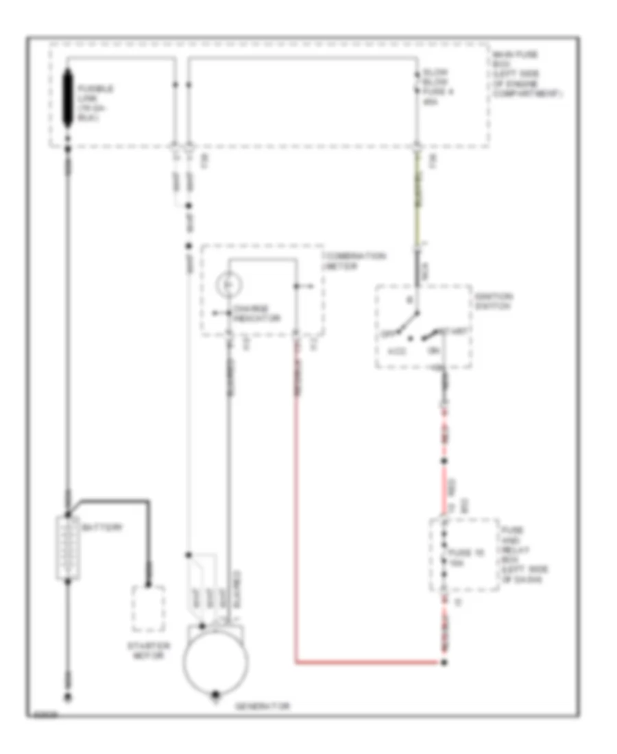
Charging Wiring Diagram for Subaru Impreza L 1997
List of elements for Charging Wiring Diagram for Subaru Impreza L 1997:
- Acc
- B52
- Battery
- Charge indicator
- Combination meter
- F36
- F38
- Fuse 15 10a
- Fuse and relay box (left side of dash)
- Generator
- I10
- I12
- Ignition switch
- Main fuse box (left side of engine compartment)
- Nca
- Nca b
- Off
- Red
- Slow blow fuse 4 45a
- Start
- Starter motor
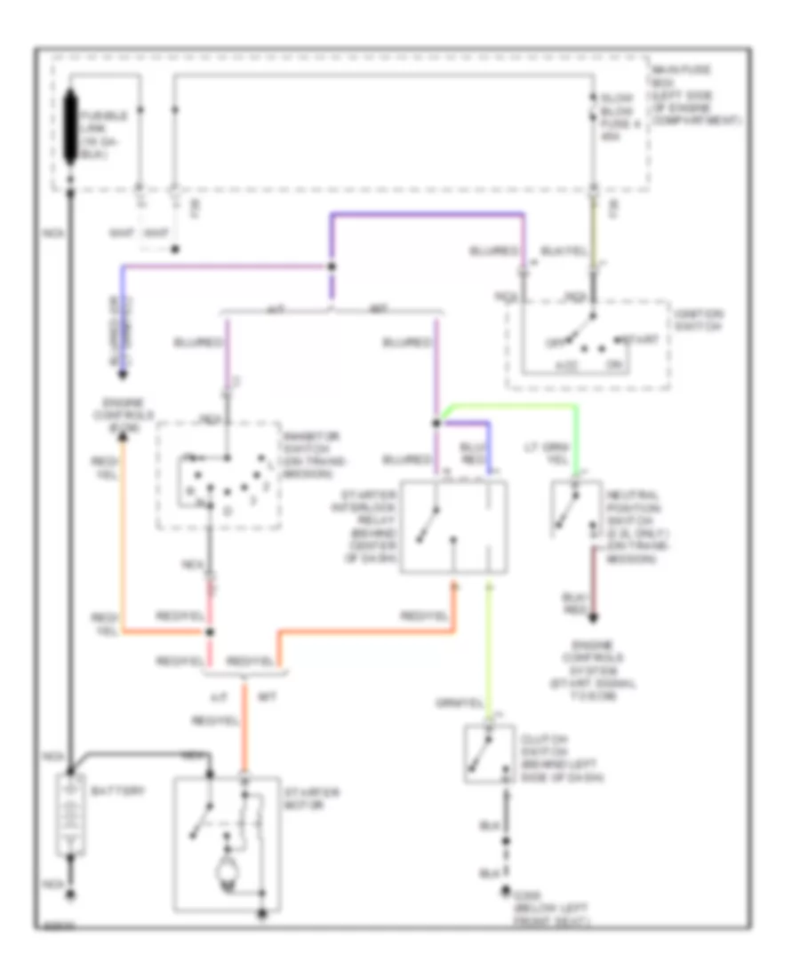
Starting Wiring Diagram for Subaru Impreza L 1997
List of elements for Starting Wiring Diagram for Subaru Impreza L 1997:
- A/t
- Acc
- Battery
- Clutch switch (behind left side of dash)
- Engine controls (ecm)
- Engine controls system (start signal to ecm)
- F36
- F38
- G300 (below left front seat)
- Ignition switch
- Inhibitor switch (on trans- mission)
- M/t
- Main fuse box (left side of engine compartment)
- Nca
- Neutral position switch (2.2l only) (on trans- mission)
- Off
- Slow blow fuse 4 45a
- Start
- Starter interlock relay (behind center of dash)
- Starter motor
SUPPLEMENTAL RESTRAINTS
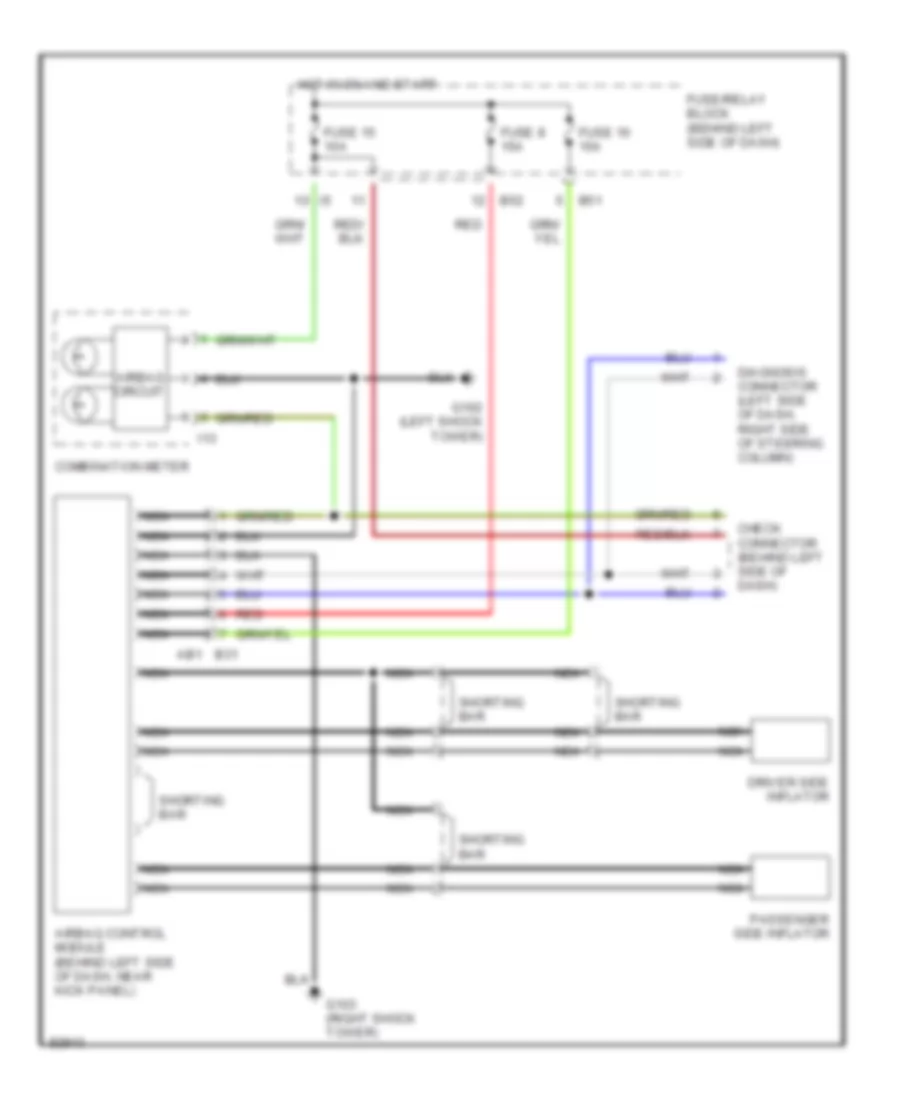
Supplemental Restraint Wiring Diagram for Subaru Impreza L 1997
List of elements for Supplemental Restraint Wiring Diagram for Subaru Impreza L 1997:
- Airbag circuit
- Airbag control module (behind left side of dash, near kick panel)
- B31 ab1
- B51
- B52
- Check connector (behind left side of dash)
- Combination meter
- Diagnosis connector (left side of dash, right side of steering column)
- Driver side inflator
- Fuse 15 10a
- Fuse 16 15a
- Fuse 8 15a
- Fuse/relay block (behind left side of dash)
- G102 (left shock tower)
- G103 (right shock tower)
- Hot in on and start
- I13
- Nca
- Passenger side inflator
- Red
- Shorting bar
TRANSMISSION
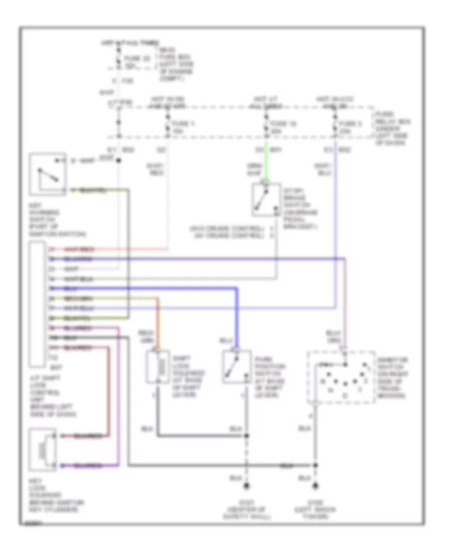
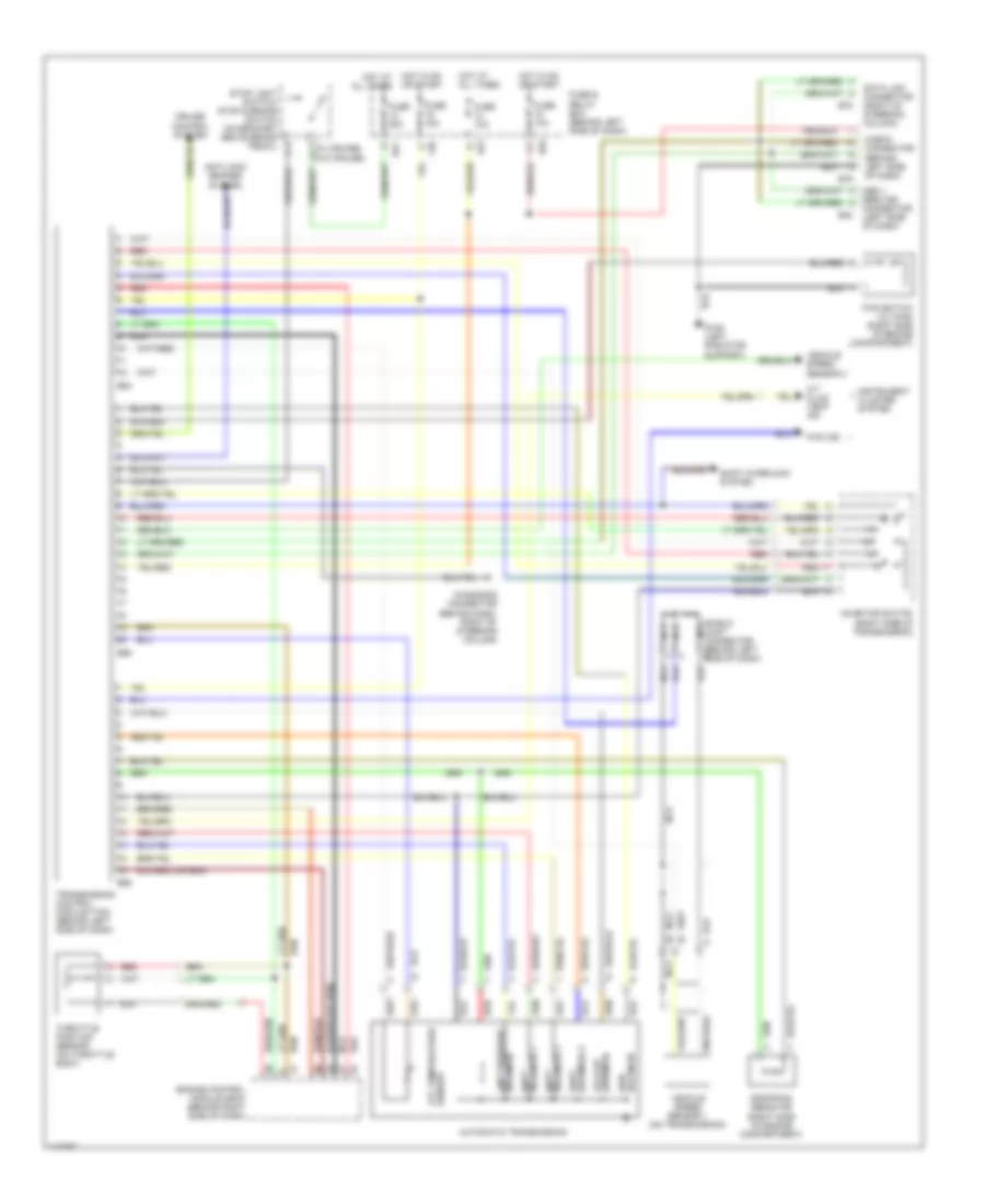
A/T Wiring Diagram for Subaru Impreza L 1997
List of elements for A/T Wiring Diagram for Subaru Impreza L 1997:
- (right side of engine compartment)
- (right side of transmission)
- (w/ cruise)
- (w/o cruise)
- A/t fluid temp ind
- Anti-lock brakes system
- Atf temperature sensor
- Automatic transmission
- Awd solenoid
- B40
- B51
- B52
- B54
- B55
- B56
- B78
- B79
- Check connector (behind left side of dash)
- Connector (left side of dash)
- Cruise control system
- Data link connector (right of steering column)
- Diagnosis connector (behind dash, right of steering column)
- Dropping resistor
- Engine control module (ecm) (behind right side of dash)
- F40
- Fuse & relay box (behind left side of dash)
- Fuse 10a
- Fuse 15a
- Fuse 20a
- Fwd ind
- Fwd switch (w/ awd) (right side of engine compartment)
- G108 (left radiator support)
- Hot at all times
- Hot in on hot at all times
- Hot in on or start
- Inhibitor switch
- Instrument cluster system
- Lock-up solenoid
- Nca
- Obd ii
- Or start
- Red
- Service
- Shield joint connector (behind left side of dash)
- Shift interlock system
- Shift solenoid 1
- Shift solenoid 3
- Solenoid 2 shift
- Solenoid line pressure
- Stop light switch/ stop & brake switch (on bracket above brake pedal)
- Throttle position sensor (on throttle body)
- Transmission control module (tcm) (behind left side of dash)
- Vehicle speed sensor 1 (on transmission)
- Vehicle speed sensor 2
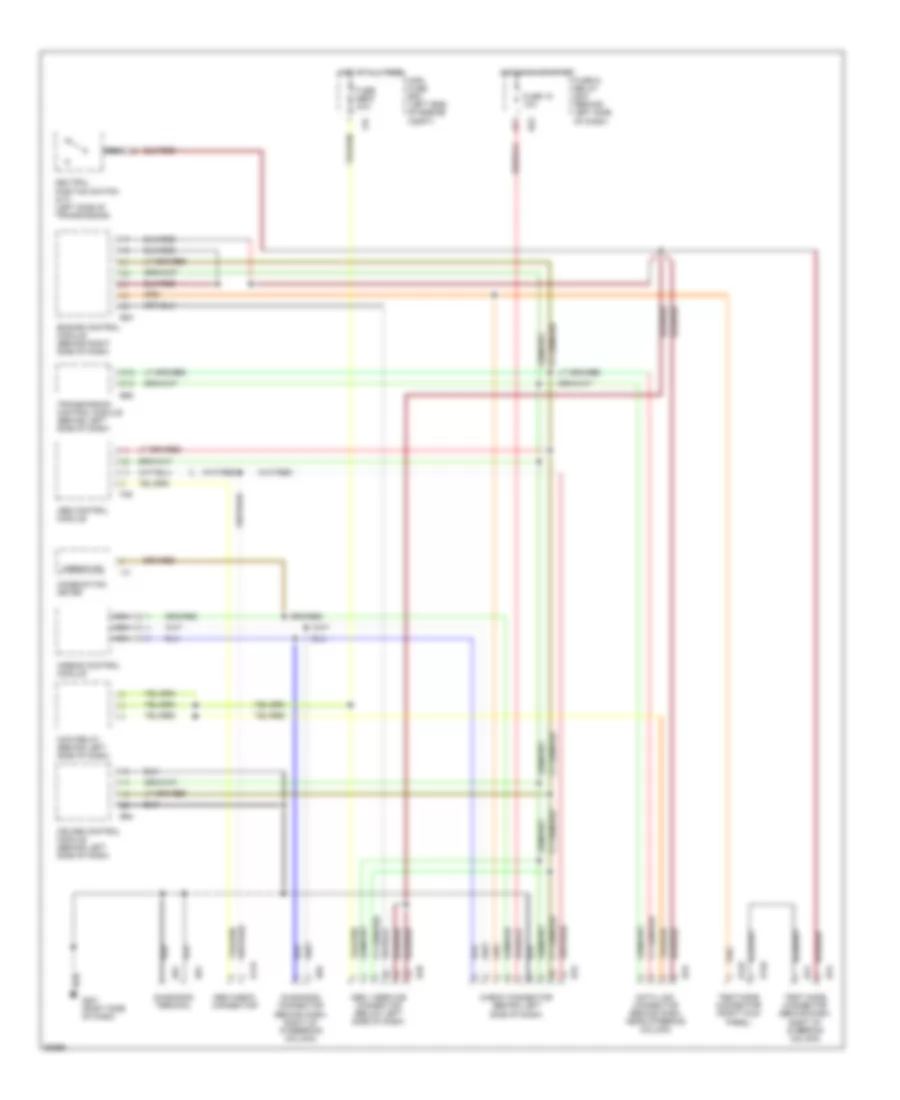
WARNING SYSTEMS
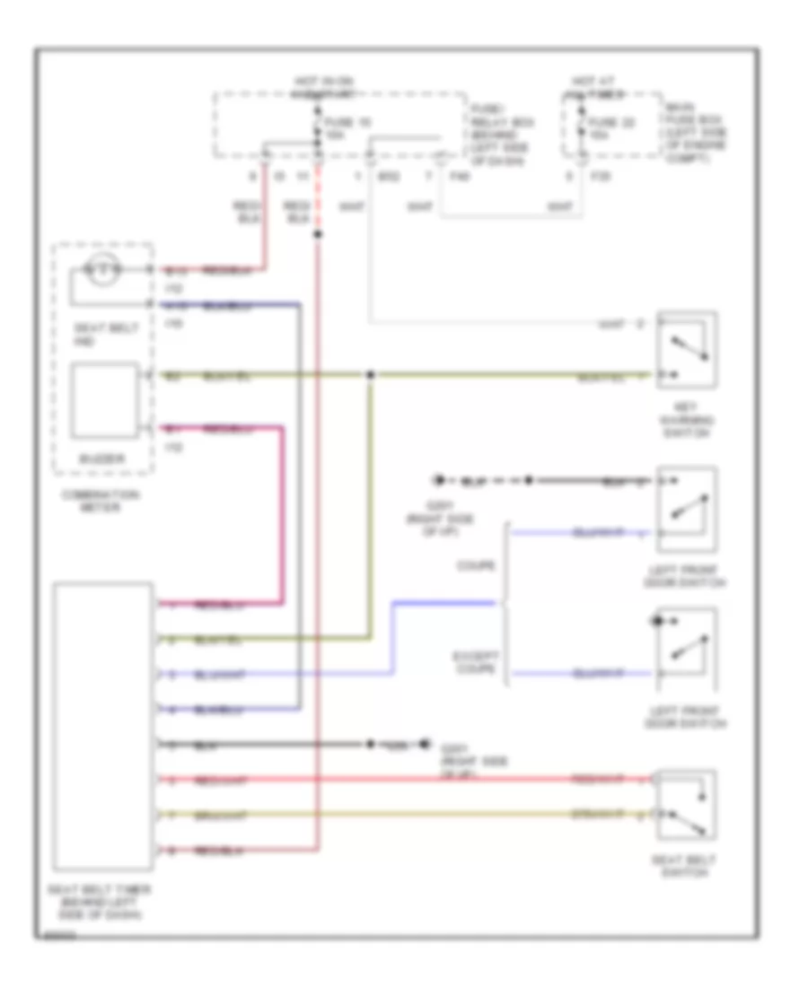
Warning System Wiring Diagrams for Subaru Impreza L 1997
List of elements for Warning System Wiring Diagrams for Subaru Impreza L 1997:
- A13
- B13
- B52
- Buzzer
- Combination meter
- Coupe
- Except coupe
- F35
- F40
- Fuse 15 10a
- Fuse 22 15a
- Fuse/ relay box (behind left side of dash)
- G201 (right side of i/p)
- Hot at all times
- Hot in on and start
- I10
- I12
- Key warning switch
- Left front door switch
- Main fuse box (left side of engine compt)
- Seat belt ind
- Seat belt switch
- Seat belt timer (behind left side of dash)
WIPER/WASHER
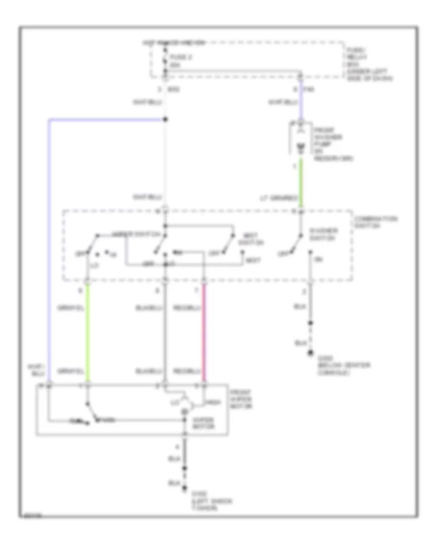
2-Speed Wiper/Washer Wiring Diagram for Subaru Impreza L 1997
List of elements for 2-Speed Wiper/Washer Wiring Diagram for Subaru Impreza L 1997:
- B52
- Combination switch
- F40
- Front washer pump (in reservoir)
- Front wiper motor
- Fuse 2 20a
- Fuse/ relay box (under left side of dash)
- G102 (left shock tower)
- G302 (below center console)
- High
- Hot in acc and on
- Mist
- Mist switch
- Off
- Park
- Run
- Washer switch
- Wiper motor
- Wiper switch
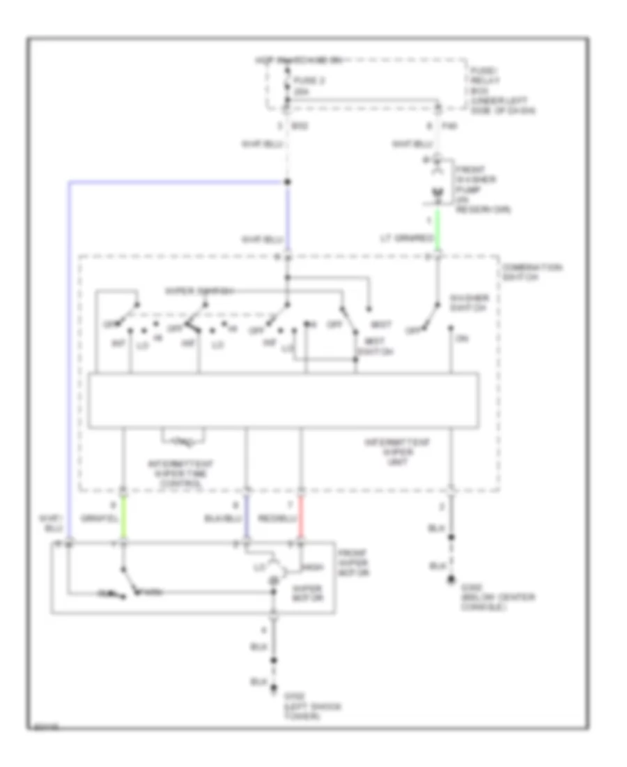
Interval Wiper/Washer Wiring Diagram for Subaru Impreza L 1997
List of elements for Interval Wiper/Washer Wiring Diagram for Subaru Impreza L 1997:
- B52
- Combination switch
- F40
- Front washer pump (in reservoir)
- Front wiper motor
- Fuse 2 20a
- Fuse/ relay box (under left side of dash)
- G102 (left shock tower)
- G302 (below center console)
- High
- Hot in acc and on
- Int
- Intermittent wiper time control
- Intermittent wiper unit
- Mist
- Mist switch
- Off
- Park
- Run
- Washer switch
- Wiper motor
- Wiper switch
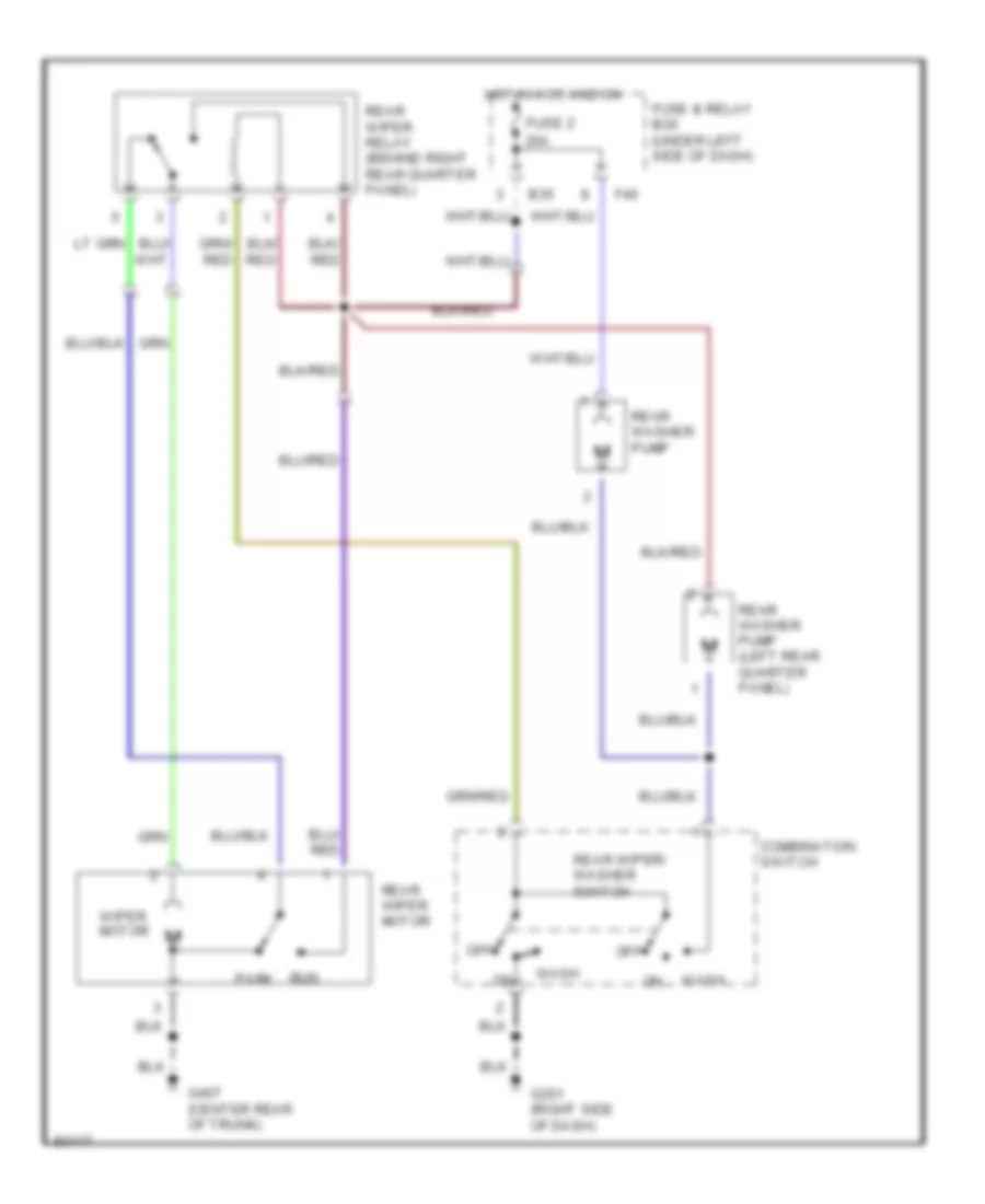
Rear Washer/Wiper Wiring Diagram for Subaru Impreza L 1997
List of elements for Rear Washer/Wiper Wiring Diagram for Subaru Impreza L 1997:
- B35
- Combination switch
- F40
- Fuse & relay box (under left side of dash)
- Fuse 2 20a
- G201 (right side of dash)
- G407 (center rear of trunk)
- Hot in acc and on
- Off
- Park
- Rear washer pump
- Rear washer pump (left rear quarter panel)
- Rear wiper motor
- Rear wiper relay (behind right rear quarter panel)
- Rear wiper/ washer switch
- Run
- Wash
- Wiper motor