Diagram sections — 24 (36 total)
AIR CONDITIONING ANTI-LOCK BRAKES COMPUTER DATA LINES COOLING FAN DEFOGGERS ENGINE PERFORMANCE EXTERIOR LIGHTS GROUND DISTRIBUTION HEADLIGHTS HORN INSTRUMENT CLUSTER INTERIOR LIGHTS POWER DISTRIBUTION POWER DOOR LOCKS POWER MIRRORS POWER TOP/SUNROOF POWER WINDOWS RADIO SHIFT INTERLOCKS STARTING/CHARGING SUPPLEMENTAL RESTRAINTS TRANSMISSION WARNING SYSTEMS WIPER/WASHER
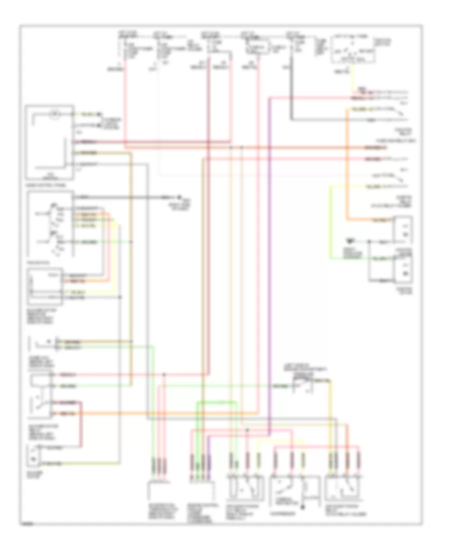
AIR CONDITIONING A/C Wiring Diagram for Subaru Impreza Outback Sport 1998 List of elements for A/C Wiring Diagram for Subaru Impreza Outback Sport 1998: 45 (left side of engine compartment) (right radiator support) (right side A/c relay holder A/c switch Acc Air conditioner fuse 10a Air conditioning cut relay (right side of firewall) Air conditioning relay (in a/c relay holder) Blower motor Blower motor relay (behind left side of dash) Blower motor resistor (behind right side of dash) Clutch Compressor Diode (a/c) (behind left side of dash) E11 Engine control module (under passenger floorboard) Evaporation thermoswitch (behind right side of dash) F27 Fan switch Fuse 10a Fuse 20 15a Fuse 20a Fuse 21 15a Fuse and relay box G109 G201 Hot at all times Hot in on or start I17 I30 Ignition switch Interior lights system Main fan motor Main fan relay Mode control panel Nca Of dash) Off Pressure switch Run Start Sub fan motor Sub-fan relay (in a/c relay holder) Thermal protector Heater Wiring Diagram for Subaru Impreza Outback Sport 1998 List of elements for Heater Wiring Diagram for Subaru Impreza Outback Sport 1998: 16 (right side Blower motor Blower motor relay (behind left side of dash) Blower motor resistor (behind right side of dash) C 1995 vftc E11 Fan switch Fuse 10a Fuse 20 15a Fuse 21 15a Fuse and relay box G201 Hot at all times Hot in on or start Of dash) Off
ANTI-LOCK BRAKES Anti-lock Brake Wiring Diagrams for Subaru Impreza Outback Sport 1998 List of elements for Anti-lock Brake Wiring Diagrams for Subaru Impreza Outback Sport 1998: 38 (w/ cruise) (w/o cruise) Abs control module (left side of engine compt) Abs g sensor (left rear of engine compt) Abs indicator B152 B159 B52 B56 Check connector (behind center of dash) Combination meter Data link connector (right of steering column) Diagnosis connector (right of steering column) F34 F41 Fuse & relay box Fuse 14 15a Fuse 16 20a Fuse 18 15a Fuse 8 20a G101 (front of right front fender) G106 (behind left headlight) Hot at all times Hot in run or start I11 I12 Left front abs sensor Left rear abs sensor Nca Pnk Red Right front abs sensor Right rear abs sensor Sbf holder Sbf-7 fuse 50a Shield joint connector (left side of eng compt) Stoplight switch (on bracket, above brake pedal) Transmission control module (behind left side of dash)
COMPUTER DATA LINES Computer Data Lines for Subaru Impreza Outback Sport 1998 List of elements for Computer Data Lines for Subaru Impreza Outback Sport 1998: 36 (behind dash, right of steeering column) Abs control module (left side of engine compt) Airbag control module (behind left side of dash) Airbag ind B125 B126 B40 B52 B56 B75 B76 B79 B81 B82 B84 Check connector (behind left side of dash) Combination meter Data link connector (right of steering column) Diagnosis connector Diagnosis terminal (left side of dash) Engine control module (under passenger floorboard) F37 F49 Fuse & relay box Fuse 18 15a G114 (left rear of engine) G203 (right kick panel) Hot at all times Hot in on and start I12 Main fuse box Red Sbf-5 fuse 30a Test mode connector (behind dash, right of steering column) Test mode connector (right kick panel) Transmission control module (behind left side of dash)
COOLING FAN Cooling Fan Wiring Diagram for Subaru Impreza Outback Sport 1998 List of elements for Cooling Fan Wiring Diagram for Subaru Impreza Outback Sport 1998: 21 (left front of engine compt) (right front of engine compt) 20a Air conditioning relay holder Engine control module (under passenger floorboard) F27 F28 F41 F66 Fuse & relay box Fuse 17 15a Fuse 18 15a G106 (behind left headlight) Hot at all times Hot in on or start Main fan Main fan motor Relay Relay Sub fan motor Sub-fan
DEFOGGERS Defogger Wiring Diagram for Subaru Impreza Outback Sport 1998 List of elements for Defogger Wiring Diagram for Subaru Impreza Outback Sport 1998: 21 B152 B158 B52 F40 F68 Fuse & relay box Fuse 1 20a Fuse 17 15a G206 (center of dash) G407 (center rear of trunk) Hot at all times Hot in on and start Interior lights system Main fuse box Nca Rear defogger Rear defogger relay Rear defogger switch Red Sedan, coupe Wagon
ENGINE PERFORMANCE
2.2L 2.2L, Engine Performance Wiring Diagrams (1 of 2) for Subaru Impreza Outback Sport 1998 List of elements for 2.2L, Engine Performance Wiring Diagrams (1 of 2) for Subaru Impreza Outback Sport 1998: 35 (behind left side of dash) fuel pump relay (behind left side of dash) main relay (below rear of vehicle, in fuel tank) fuel pump & fuel gauge module (brhind left side of dash, taped to harn) check connector (on right side of trunk) A/c system B152 B158 Camshaft position sensor (on left of eng) Crankshaft position sensor (on lower front of eng) Engine control module (under passenger floorboard) F37 Fuel gauge Fuel gauge sub module (awd) (below rear of vehicle, near fuel tank) Fuel injectors Fuel temp gauge Fuse & relay box Fuse 10a Fuse 15a G103 (right front shock tower) G107 (behind right headlamp) G114 (left rear of eng) G407 (center rear of trunk) Hot at all times Hot in run or start Ignition coil (on top front of eng) Ignitor (on center of firewall) Knock sensor (on left side of eng) Main fuse box Nca Oxygen sensor (front) (on front of front catalytic converter) Oxygen sensor (rear) (on rear of rear catalytic converter) Red Sbf-5 30a Trans- missions control system 2.2L, Engine Performance Wiring Diagrams (2 of 2) for Subaru Impreza Outback Sport 1998 List of elements for 2.2L, Engine Performance Wiring Diagrams (2 of 2) for Subaru Impreza Outback Sport 1998: 48 (m/t) (on air cleaner housing) (right front of eng compt) A/c system A/t Acc Boost sensor Cooling fan system Data link connector (behind dash, right of Dignosis connector (behind dash, right of steering column) Egr solenoid (on top left side of eng, at egr valve) Engine control module (under passenger floorboard) Engine coolant temperature sensor (top right front of eng) F68 Fuel tank pressure control solenoid valve (on right front of fuel tank) Fuse 15a G114 (left rear of eng) G202 (center of dash) Hot at all times I10 I12 Idle air control solenoid valve (on throttle body assembly) Ignition switch Inhibitor switch Instrument cluster M/t Main fuse box Malfunction indicator lamp Mass air flow sensor Nca Neutral position switch (on left side of eng compt) Off Pnk Pressure sources switching solenoid (on right side of eng compt) Purge control solenoid valve (on top right front of eng) Red Shield joint connector (behind right kick panel) Speedo- meter circuit Start Starter interlock relay (left side of dash) Starting/ charging system Steering column) Tacho- meter Test mode connector (behind dash, right of steering column) Throttle position sensor (on throttle body assembly) Transmissions control system Vehicle speed sensor 2 (side of trans- mission) Vent control solenoid valve (below rear of vehicle, near fuel tank)
2.5L 2.5L, Engine Performance Wiring Diagrams (1 of 2) for Subaru Impreza Outback Sport 1998 List of elements for 2.5L, Engine Performance Wiring Diagrams (1 of 2) for Subaru Impreza Outback Sport 1998: 35 (behind left side of dash) fuel pump relay (behind left side of dash) main relay (below rear of vehicle, in fuel tank) fuel pump & fuel gauge module (brhind left side of dash, taped to harn) check connector (on right side of trunk) A/c system B152 B158 Camshaft position sensor (on left of eng) Crankshaft position sensor (on lower front of eng) Engine control module (under passenger floorboard) F37 Fuel gauge Fuel gauge sub module (awd) (below rear of vehicle, near fuel tank) Fuel injectors Fuel temp gauge Fuse & relay box Fuse 10a Fuse 15a G103 (right front shock tower) G107 (behind right headlamp) G114 (left rear of eng) G407 (center rear of trunk) Hot at all times Hot in run or start Ignition coil (on top front of eng) Ignitor (on center of firewall) Knock sensor (on left side of eng) Main fuse box Nca Oxygen sensor (front) (on front of front catalytic converter) Oxygen sensor (rear) (on rear of rear catalytic converter) Red Sbf-5 30a Trans- missions control system 2.5L, Engine Performance Wiring Diagrams (2 of 2) for Subaru Impreza Outback Sport 1998 List of elements for 2.5L, Engine Performance Wiring Diagrams (2 of 2) for Subaru Impreza Outback Sport 1998: 48 (m/t) (on air cleaner housing) (right front of eng compt) A/c system A/t Acc Boost sensor Cooling fan system Data link connector (behind dash, right of Dignosis connector (behind dash, right of steering column) Egr solenoid (on top left side of eng, at egr valve) Engine control module (under passenger floorboard) Engine coolant temperature sensor (top right front of eng) F68 Fuel tank pressure control solenoid valve (on right front of fuel tank) Fuse 15a G114 (left rear of eng) G202 (center of dash) Hot at all times I10 I12 Idle air control solenoid valve (on throttle body assembly) Ignition switch Inhibitor switch Instrument cluster M/t Main fuse box Malfunction indicator lamp Mass air flow sensor Nca Neutral position switch (on left side of eng compt) Off Pnk Pressure sources switching solenoid (on right side of eng compt) Purge control solenoid valve (on top right front of eng) Red Shield joint connector (behind right kick panel) Speedo- meter circuit Start Starter interlock relay (left side of dash) Starting/ charging system Steering column) Tacho- meter Test mode connector (behind dash, right of steering column) Throttle position sensor (on throttle body assembly) Transmissions control system Vehicle speed sensor 2 (side of trans- mission) Vent control solenoid valve (below rear of vehicle, near fuel tank)
EXTERIOR LIGHTS Back-up Lamps Wiring Diagram for Subaru Impreza Outback Sport 1998 List of elements for Back-up Lamps Wiring Diagram for Subaru Impreza Outback Sport 1998: 14 A/t B52 Back-up Back-up light Back-up light switch (left side of eng compt) Fuse & relay box Fuse 18 15a G407 (center rear of trunk) Hot in on and start Inhibitor switch (right side of transaxle) Left rear combination lamp Light M/t Right rear combination lamp Exterior Lamps Wiring Diagram for Subaru Impreza Outback Sport 1998 List of elements for Exterior Lamps Wiring Diagram for Subaru Impreza Outback Sport 1998: 61 (center rear of trunk) (or (right kick B158 B159 B51 B52 B69 B71 Combination meter Combination switch F36 F37 F40 F41 F68 Fuse & relay box Fuse 16 20a Fuse 18 15a Fuse 5 10a Fuse 6 15a Fuse 7 20a G107 (behind right headlight) G203 G203 (right kick panel) G206 (center of dash) G407 Hazard switch Head High mount stop light Hot at all times Hot in on and start I10 I12 Interior lights system Left front clearance light Left front turn light Left license plate light Left rear combination lamp Left side turn light Left turn ind Light switch Main fuse box Off Panel) Park Parking switch Right front clearance light Right front turn light Right license plate light Right rear combination lamp Right side turn light Right turn ind Sbf-2 fuse 50a Stop light Stoplight switch (on bracket, above brake pedal) Tail & illumination relay Tail light Turn & hazard module (right of steering column) Turn light Turn signal switch
GROUND DISTRIBUTION Ground Distribution Wiring Diagram (1 of 2) for Subaru Impreza Outback Sport 1998 List of elements for Ground Distribution Wiring Diagram (1 of 2) for Subaru Impreza Outback Sport 1998: 91 A/t shift lock control module Abs control module Abs shield joint connector Audio ground B104 B106 B120 B121 B16 B32 B42 B47 B57 B81 Brake fluid level switch Clutch switch (m/t) D39 D43 D46 D48 D62 Daytime running light resistor Diagnosis terminal F16 F17 F19 F21 F49 F51 F52 F53 F54 F62 F67 F70 Front foglight adapter cord Front wiper motor Fuel pump & fuel gauge module Fwd switch G102 (left front shock tower) G103 (right front shock tower) G106 (behind left headlight) G107 (behind right headlight) G203 (right kick panel) G206 (center of dash) G407 (center rear of trunk) High-mount stoplight (coupe- rear spoiler) High-mount stoplight (sedan) High-mount stoplight (wagon) Horn Inhibitor switch (a/t) Left front clearance light Left front door switch (coupe) Left front foglight Left front turn signal light Left license plate light Left rear combination light Left side turn signal light Main relay Power window and sunroof relay Power window main switch (coupe) Power window main switch (sedan & wagon) R12 R19 R26 R28 R32 R58 R66 R76 R77 R93 Radiator main fan motor Radiator sub fan motor Radio Rear defogger (wagon) Rear gate latch switch Rear wiper motor Remote control rearview mirror switch Right door lock switch Right front clearance light Right front door switch (coupe) Right front foglight Right front turn signal light Right license plate light Right rear combination light Right side turn signal light Seat belt switch To daytime running light control module (diagram 2 of 2) To illumination control module (diagram 2 of 2) Turn & hazard module Ground Distribution Wiring Diagram (2 of 2) for Subaru Impreza Outback Sport 1998 List of elements for Ground Distribution Wiring Diagram (2 of 2) for Subaru Impreza Outback Sport 1998: 53 (m/t) Air bag control module B13 B166 B167 B169 B177 B25 B40 B43 B54 B55 B56 B70 B71 B76 B79 B92 B96 Blower fan switch Check connector Clutch switch (cruise control) Combination meter Combination switch Data link connector Daytime running light control module Door lock timer Engine control module From fuel pump & fuel gauge module (diagram 1 of 2) Fuel pump & fuel gauge module G102 (left front shock tower) G103 (right front shock tower) G114 (left rear of engine) G203 (right kick panel) G206 (center of dash) I11 I12 I18 Ignitor Illumination control module Key warning module Lighting switch Nca Neutral position switch (m/t) Parking position switch & shift lock solenoid R58 Rear defogger switch Shield joint connector Test mode connector Transmission Transmission control module Vehicle speed sensor Wiper & washer switch
HEADLIGHTS Headlight Wiring Diagram, with DRL for Subaru Impreza Outback Sport 1998 List of elements for Headlight Wiring Diagram, with DRL for Subaru Impreza Outback Sport 1998: 52 (a/t) Acc Alternator B158 B52 B71 B72 Combination meter Combination switch Daytime running light control module (right kick panel) Daytime running light diode (right side of dash) Daytime running light hi beam relay (right kick panel) Daytime running light relay (right kick panel) Daytime running light resistor (right side of eng compt) Dimmer/ passing switch F39 Front foglight adapter cord Front foglight diode (right side of dash) Front foglight relay (left of steering column) Front foglight switch Fuse & relay box Fuse 18 15a Fuse 7 15a Fuse 8 15a Fuse 9 15a G102 (left front shock tower) G103 (right front shock tower) G107 (behind right headlight) Head Hi beam ind Hot at all times Hot in on and start I10 Ignition switch Inhibitor switch (right side of transaxle) Instrument cluster system (charge indicator) Instrument cluster system (park brake warning indicator) Interior lights system Left front fog- light Left headlight Left headlight relay Light switch Main fuse box Off Park Parking brake switch (base of park brake lever) Pass Red Right headlight Right headlight relay Start Starting circuit Headlight Wiring Diagram, without DRL for Subaru Impreza Outback Sport 1998 List of elements for Headlight Wiring Diagram, without DRL for Subaru Impreza Outback Sport 1998: 37 Acc B158 B71 B72 Combination meter Combination switch Dimmer & passing switch F37 F39 Flash Front foglight adapter cord Front foglight relay (left of steering column) Front foglight switch Fuse & relay box Fuse 7 15a Fuse 8 15a Fuse 9 15a G107 (behind right headlight) G203 (right kick panel) Head Hi beam ind Hot at all times I10 Ignition switch Interior lights system Left front foglight Left headlight Left headlight relay Light switch Main fuse box Off Park Red Right front foglight Right headlight Right headlight relay Start
HORN Horn Wiring Diagram for Subaru Impreza Outback Sport 1998 List of elements for Horn Wiring Diagram for Subaru Impreza Outback Sport 1998: 11 (w/ cruise control) (w/o cruise control) F37 F39 Fuse 6 15a G106 (behind left headlight) Horn Horn relay Horn switch Hot at all times Main fuse box
INSTRUMENT CLUSTER Instrument Cluster Wiring Diagram for Subaru Impreza Outback Sport 1998 List of elements for Instrument Cluster Wiring Diagram for Subaru Impreza Outback Sport 1998: 74 A/t oil temp ind A10 A11 A12 A13 Abs ind Airbag warning ind Anti-lock brakes system B10 B152 B52 B55 B56 Brake fluid level switch (on brake fluid reservoir) C10 C11 C12 C13 Charge ind Clock Combination meter Door warning ind Engine control module (under passenger floorboard) Engine controls system Exterior lights system F40 F68 Fuel gauge Fuel gauge module (in fuel tank) Fuel gauge sub module (near fuel tank) Fuse & relay box Fuse 12 10a Fuse 18 15a Fuse 2 15a Fuse 9 15a Fwd ind G102 (left front shock tower) G114 (left rear of engine) G206 (center of dash) Headlights system Hi beam ind Hold ind Hot at all times Hot in accy and on Hot in on and start Hot w/ tail & illumination relay energized I10 I11 I12 Illumination lamps (4) Info not available Interior lights system Left turn ind Low fuel warning ind Low ind (awd) Main fuse box Malfunction indicator Nca Oil pressure ind Oil pressure switch (front of engine) Park brake/ fluid level warning ind Parking brake switch (base of park brake lever) Power ind Red Right turn ind Seat belt warning ind Speedometer Starting/charging system Tachometer Temperature gauge Thermometer (top right front of engine) Transmission control module (left side of dash) Vehicle speed sensor 2 (on side of transmission) Warnings system
INTERIOR LIGHTS Interior Light Wiring Diagram for Subaru Impreza Outback Sport 1998 List of elements for Interior Light Wiring Diagram for Subaru Impreza Outback Sport 1998: 50 (not used) A/t selector lever illumination light B152 B158 B51 B52 B71 Cd illumination light Clock Combination meter Combination switch Coupe Cruise control main switch illumination light Door ind F40 F68 Front foglight switch illumination light Fuse & relay box Fuse 12 10a Fuse 2 15a Fuse 7 20a G203 (right kick panel) G407 (center rear of trunk) Hazard switch illumination light Head Hot at all times Hot in on and start I10 I11 I12 Illumination control module (front of console) Left front door switch Left rear door switch Light switch Main fuse box Mode control panel illumination light Nca Off Park Radio illumin- ation light Rear defogger switch illumination light Rear gate latch switch (wagon) Right front door switch Right rear door switch Room light Sedan, wagon Spot- light Tail & illumination relay Trunk room light (sedan, coupe) Trunk room light switch (sedan, coupe)
POWER DISTRIBUTION Power Distribution Wiring Diagram (1 of 3) for Subaru Impreza Outback Sport 1998 List of elements for Power Distribution Wiring Diagram (1 of 3) for Subaru Impreza Outback Sport 1998: 74 (not used) A/t shift lock control module Abs control module B152 B158 B159 B51 B52 B56 Battery Blower motor relay Combination meter Data link connector Door lock timer Engine control module Exterior lights system (parking switch) F26 F36 F37 F39 F40 F41 F68 Front fog light relay Fuel pump relay Fuse & relay box Fuse 1 15a Fuse 1 20a Fuse 2 15a Fuse 3 10a Fuse 4 10a Fuse 5 10a Fuse 5 15a Fuse 6 15a Fuse 7 15a Fuse 7 20a Fuse 8 15a Fuse 8 20a Fuse 9 15a Generator Hazard switch Headlights system Horn relay I12 Key warning switch Left front clearance light Left headlight relay Left license plate light Left rear combination light Main fuse box Main relay Nca Parking switch Power window & sunroof circuit breaker Power window & sunroof relay Radio Rear defogger relay Red Right front clearance light Right headlight relay Right license plate light Right rear combination light Room light Sbf-1 fuse 80a Sbf-3 fuse 50a Sbf-5 fuse 30a Sbf-6 fuse 30a Spot light Starter motor To ignition switch (diagram 2 of 3) To main fuse box sbf-4 (diagram 2 of 3) To tail & illumination relay (diagram 3 of 3) Transmission control module Trunk room light (sedan, coupe) Power Distribution Wiring Diagram (2 of 3) for Subaru Impreza Outback Sport 1998 List of elements for Power Distribution Wiring Diagram (2 of 3) for Subaru Impreza Outback Sport 1998: 66 (m/t) (not used) (w/ cruise) (w/o cruise) 20a A/t A/t shift lock control module Abs control module Acc Air conditioning relay holder B119 B152 B159 B167 B52 B72 Clock Combination meter Combination switch Engine control module F27 F28 F34 F35 F36 F38 F40 From main fuse box headlight relays (diagram 1 of 3) From main fuse box sbf-1 (diagram 1 of 3) Front washer motor Front wiper & washer switch Front wiper motor Fuse & relay box Fuse 10 15a Fuse 15 20a Fuse 16 20a Fuse 19 20a Fuse 4 20a Fuse 9 15a G106 (behind left headlight) G206 (behind center of dash) G407 (center rear of trunk) Generator I11 Ignition switch Inhibitor switch M/t Main fan relay Main fuse box Nca Neutral position switch Off Radio Rear washer motor Rear wiper motor Rear wiper relay Remote control rearview mirror switch Sbf holder Sbf-2 fuse 50a Sbf-4 fuse 50a Sbf-7 fuse 50a Start Starter interlock relay Stop & brake switch (w/ cruise) stoplight switch (w/o cruise) Sub fan relay To fuse & relay box fuse 14 (diagram 3 of 3) To fuse & relay box fuse 18 (diagram 3 of 3) Power Distribution Wiring Diagram (3 of 3) for Subaru Impreza Outback Sport 1998 List of elements for Power Distribution Wiring Diagram (3 of 3) for Subaru Impreza Outback Sport 1998: 69 (4) (not used) A/t selector lever illumination light A/t shift lock control module Abs control module Air conditioning relay Air conditioning relay holder Airbag control module B152 B158 B159 B168 B31 B51 B52 B54 B55 Back-up light switch (m/t) Blower motor relay Cd illumination light Check connector Clock Combination meter Compressor Cruise control main switch illumination light Daytime running light control module Daytime running light hi-beam relay Daytime running light relay Engine control module Exterior lights system F28 F31 F40 F41 F66 From fuse/relay box f40 pin 9 (diagram 1 of 3) From ignition switch (diagram 2 of 3) Front fog light switch illumination light Fuel pump relay Fuse & relay box Fuse 11 15a Fuse 12 10a Fuse 14 15a Fuse 17 15a Fuse 18 15a Fuse 6 15a Hazard switch Hazard switch illumination light I10 I12 Ignition coil Illumination control module Inhibitor switch (a/t) Key warning module Main fan relay Mode control panel Mode control panel illumination light Nca Parking switch Power window & sunroof relay Radio illumination light Rear defogger relay Rear defogger switch Rear defogger switch illumination light Red Sub fan relay Tail & illumination relay Thermal protector Transmission control module
POWER DOOR LOCKS Power Door Lock Wiring Diagram for Subaru Impreza Outback Sport 1998 List of elements for Power Door Lock Wiring Diagram for Subaru Impreza Outback Sport 1998: 15 Coupe Door lock timer (right side of glove box) F68 Fuse 5 15a G203 (right kick panel) Hot at all times Left door lock switch Left front door lock actuator Left rear door lock actuator Main fuse box Others Rear gate lock actuator Right door lock switch Right front door lock actuator Right rear door lock actuator
POWER MIRRORS Power Mirror Wiring Diagram for Subaru Impreza Outback Sport 1998 List of elements for Power Mirror Wiring Diagram for Subaru Impreza Outback Sport 1998: 13 B52 Fuse & relay box Fuse 4 20a G203 (right kick panel) Hot in acc & on Left rear- view mirror Left/ right m Mirror select switch Motor Red Remote control rearview mirror switch Right rear- view mirror Up/ down m
POWER TOP/SUNROOF Power Top/Sunroof Wiring Diagrams for Subaru Impreza Outback Sport 1998 List of elements for Power Top/Sunroof Wiring Diagrams for Subaru Impreza Outback Sport 1998: 18 B52 Close F36 Fuse & relay box Fuse 18 10a G203 (right kick panel) G908 (center front of roof) Hot at all times Hot in on & start Main fuse box Power window & sun roof circuit breaker (left side of dash) Power window & sun roof relay (left side of dash) Red Sbf-6 fuse 30a Sun roof control module (center underside of roof) Sun roof motor (center underside of roof) Sun roof switch Tilt/ slide
POWER WINDOWS Power Window Wiring Diagram, Coupe for Subaru Impreza Outback Sport 1998 List of elements for Power Window Wiring Diagram, Coupe for Subaru Impreza Outback Sport 1998: 19 B152 B52 Down Fuse & relay box Fuse 18 15a G203 (right kick panel) Hot at all times Hot in on & start Left front Left front power window motor Lock Lock- out switch Power tops system Power window & sun roof circuit breaker Power window & sun roof relay (left side of dash) Power window main switch Right front Right front power window motor Right front power window sub switch Power Window Wiring Diagram, Sedan & Wagon for Subaru Impreza Outback Sport 1998 List of elements for Power Window Wiring Diagram, Sedan & Wagon for Subaru Impreza Outback Sport 1998: 25 B152 B52 Down Fuse & relay box Fuse 18 15a G203 (right kick panel) Hot at all times Hot in on & start Left front Left front power window motor Left rear Left rear power window motor Left rear power window sub switch Lock Lock- out switch Power tops system Power window & sun roof circuit breaker Power window & sun roof relay (left side of dash) Power window main switch Right front Right front power window motor Right front power window sub switch Right rear Right rear power window motor Right rear power window sub switch
RADIO Radio Wiring Diagrams for Subaru Impreza Outback Sport 1998 List of elements for Radio Wiring Diagrams for Subaru Impreza Outback Sport 1998: 20 Audio ground (center of dash) B52 F40 F68 Fuse & relay box Fuse 2 15a Fuse 9 15a G206 (center of dash) Hot at all times Hot in acc & on Interior lights system Left front door speaker Left rear speaker (sedan & coupe) Left rear speaker (wagon) Main fuse box Radio (left side of dash) Red Right front door speaker Right rear speaker (sedan & coupe) Right rear speaker (wagon)
SHIFT INTERLOCKS Shift Interlock Wiring Diagram for Subaru Impreza Outback Sport 1998 List of elements for Shift Interlock Wiring Diagram for Subaru Impreza Outback Sport 1998: 23 A/t shift lock control module (behind left side of dash) B159 B52 B57 F37 Fuse & relay box Fuse 14 15a Fuse 16 20a Fuse 4 20a Fuse 6 15a G102 (left front shock tower) G203 (right kick panel) Hot at all times Hot in accy and on Hot in on and start Inhibitor switch (on right side of transaxle) Key lock solenoid (behind ignition key cylinder) Key warning switch (part of ignition switch) Main fuse box Park position switch (at base of shift lever) Red Shift lock solenoid (at base of shift lever) Stoplight switch (on bracket, above brake pedal)
STARTING/CHARGING Charging Wiring Diagram for Subaru Impreza Outback Sport 1998 List of elements for Charging Wiring Diagram for Subaru Impreza Outback Sport 1998: 25 Acc B152 B159 B52 B72 Battery Charge indicator Combination meter F35 F38 F39 Fuse & relay box Fuse 18 15a Fuse 3 10a Generator I10 I12 Ignition switch Main fuse box Nca Off Sbf-1 fuse 80a Sbf-4 fuse 50a Start Starter motor Starting Wiring Diagram for Subaru Impreza Outback Sport 1998 List of elements for Starting Wiring Diagram for Subaru Impreza Outback Sport 1998: 21 A/t Acc Battery Clutch switch (on bracket, above clutch pedal) Engine control module Engine controls system F38 G102 (left front shock tower) Ignition switch Inhibitor switch (right side of trans- mission) M/t Main fuse box Nca Neutral position switch (left side of transmission) Off Relay (right of steering column) Sbf-1 fuse 80a Sbf-4 fuse 50a Start Starter inter- lock Starter motor
SUPPLEMENTAL RESTRAINTS Supplemental Restraint Wiring Diagram for Subaru Impreza Outback Sport 1998 List of elements for Supplemental Restraint Wiring Diagram for Subaru Impreza Outback Sport 1998: 22 Airbag circuit Airbag control module (ahead of front floor tunnel) B152 B51 Check Combination meter Connector (behind left side of dash) Diagnosis connector (behind left side of dash) Driver inflator Fuse & relay box Fuse 15a G104 (rear of left front fender) G105 (rear of right front fender) G206 (on left dash support) Hot in on and start I12 Left front sub sensor Nca Passenger inflator Pnk Red Right front sub sensor
TRANSMISSION A/T Wiring Diagram for Subaru Impreza Outback Sport 1998 List of elements for A/T Wiring Diagram for Subaru Impreza Outback Sport 1998: 54 (left front of shock tower) g102 (right side of engine compartment) (right side of transaxle) (w/ cruise) (w/o cruise) A/t oil temp ind Anti-lock brakes system Atf temperature sensor Automatic transmission Awd solenoid B158 B159 B40 B54 B55 B56 B79 Check connector (behind left side of dash) Combination meter Connector (dlc) (left of steering column) Cruise control system Data link Diagnosis connector (right of steering column) Dropping resistor Engine control module (ecm) (under passenger floorboard) F37 Fuse & relay box (left side of engine compartment) Fuse 10a Fuse 15a Fuse 20a Fwd ind Fwd switch (w/ awd) (right side of eng compt) G107 (behind right headlight) G203 (right kick panel) Hot at all times Hot in on or start I10 I11 Inhibitor switch Lock-up solenoid Main fuse box Nca Pnk Red Shield joint connector (behind left side of dash) Shift solenoid 1 Shift solenoid 3 Solenoid 2 shift Solenoid line pressure Speedometer Stop light switch/ stop & brake switch (on brake pedal bracket) Throttle position sensor (on throttle body) Transmission control module (behind left side of dash) Vehicle speed sensor 1 (on transmission) Vehicle speed sensor 2 (back of gauge assembly)
WARNING SYSTEMS Warning System Wiring Diagrams for Subaru Impreza Outback Sport 1998 List of elements for Warning System Wiring Diagrams for Subaru Impreza Outback Sport 1998: 18 B52 Combination meter Coupe Except coupe F37 Fuse & relay box Fuse 15 10a Fuse 6 15a G203 (right kick panel) Hot at all times Hot in on and start I12 Key warning module (left side of dash) Key warning switch Left front door switch Main fuse box Seat belt ind Seat belt switch
WIPER/WASHER Front Wiper/Washer Wiring Diagram for Subaru Impreza Outback Sport 1998 List of elements for Front Wiper/Washer Wiring Diagram for Subaru Impreza Outback Sport 1998: 23 B159 B70 Combination switch Front washer motor (washer fluid reservoir) Front wiper motor Fuse & relay box (left side of engine compt) Fuse 15 20a G102 (left front shock tower) G203 (right kick panel) High Hot in accy & on Int Intermittent wiper time control Intermittent wiper unit Mist Mist switch Off Park Rear wiper circuit Run Washer switch Wiper motor Wiper switch Rear Wiper/Washer Wiring Diagram for Subaru Impreza Outback Sport 1998 List of elements for Rear Wiper/Washer Wiring Diagram for Subaru Impreza Outback Sport 1998: 19 (impreza) g405 (right rear cargo area) B159 B70 Combination switch Front wiper/ washer circuit Fuse & relay box Fuse 15 20a G203 (right kick panel) G405 (forester) (right rear of cargo compt) Hot in accy & on Off Park Rear washer motor (washer reservoir) Rear wiper motor Rear wiper relay (on right rear of cargo area) Rear wiper/ washer switch Run Wash Wiper motor