Diagram sections — 27 (49 total)
AIR CONDITIONING ANTI-LOCK BRAKES ANTI-THEFT BODY CONTROL MODULES COMPUTER DATA LINES COOLING FAN CRUISE CONTROL DEFOGGERS ENGINE PERFORMANCE EXTERIOR LIGHTS GROUND DISTRIBUTION HEADLIGHTS HORN INSTRUMENT CLUSTER INTERIOR LIGHTS POWER DISTRIBUTION POWER DOOR LOCKS POWER MIRRORS POWER SEATS POWER WINDOWS RADIO SHIFT INTERLOCK STARTING/CHARGING SUPPLEMENTAL RESTRAINTS TRANSMISSION WARNING SYSTEMS WIPER/WASHER
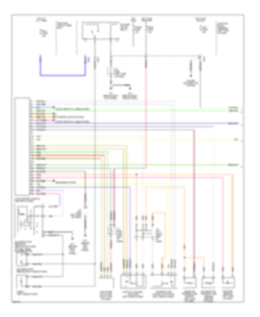
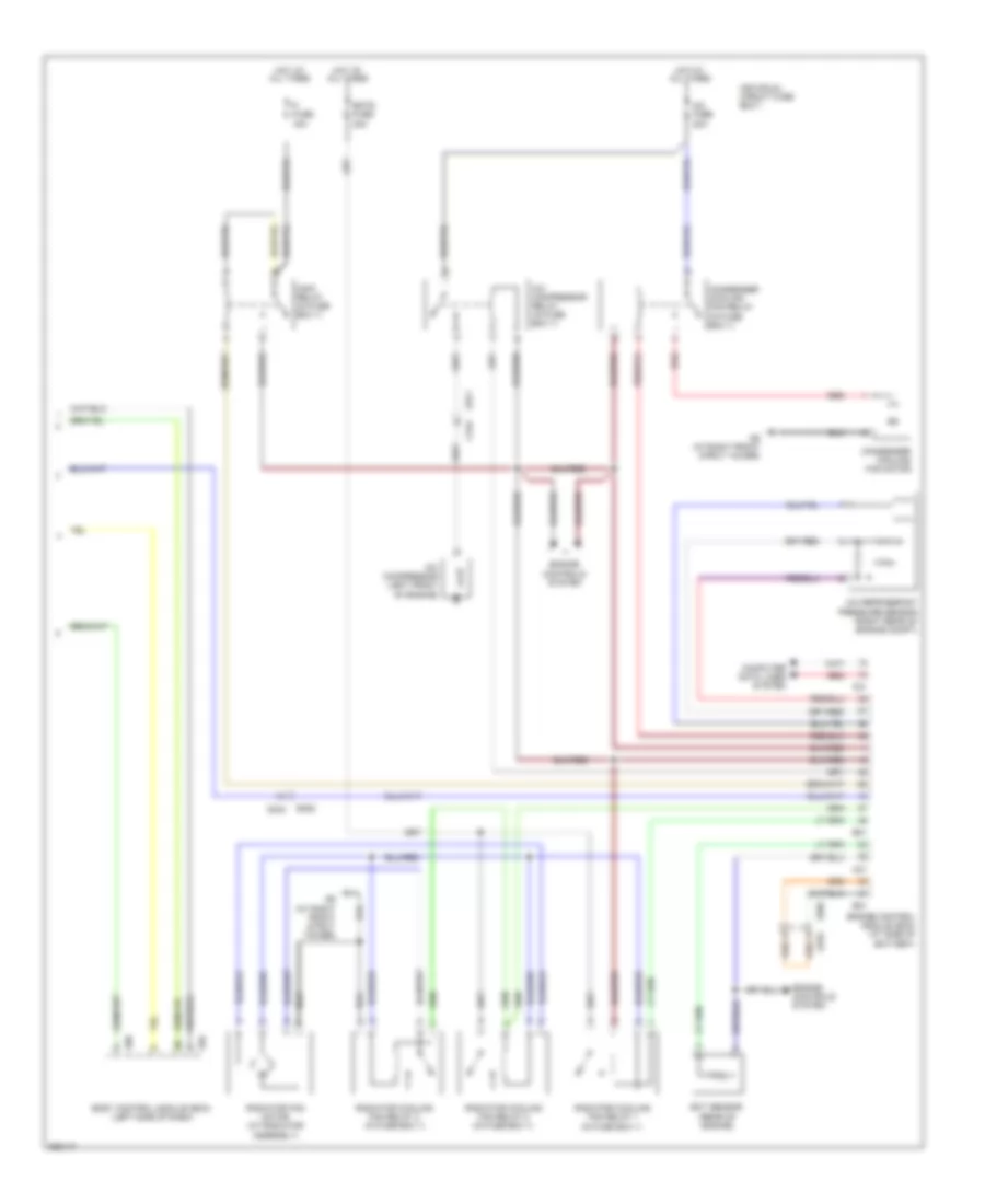
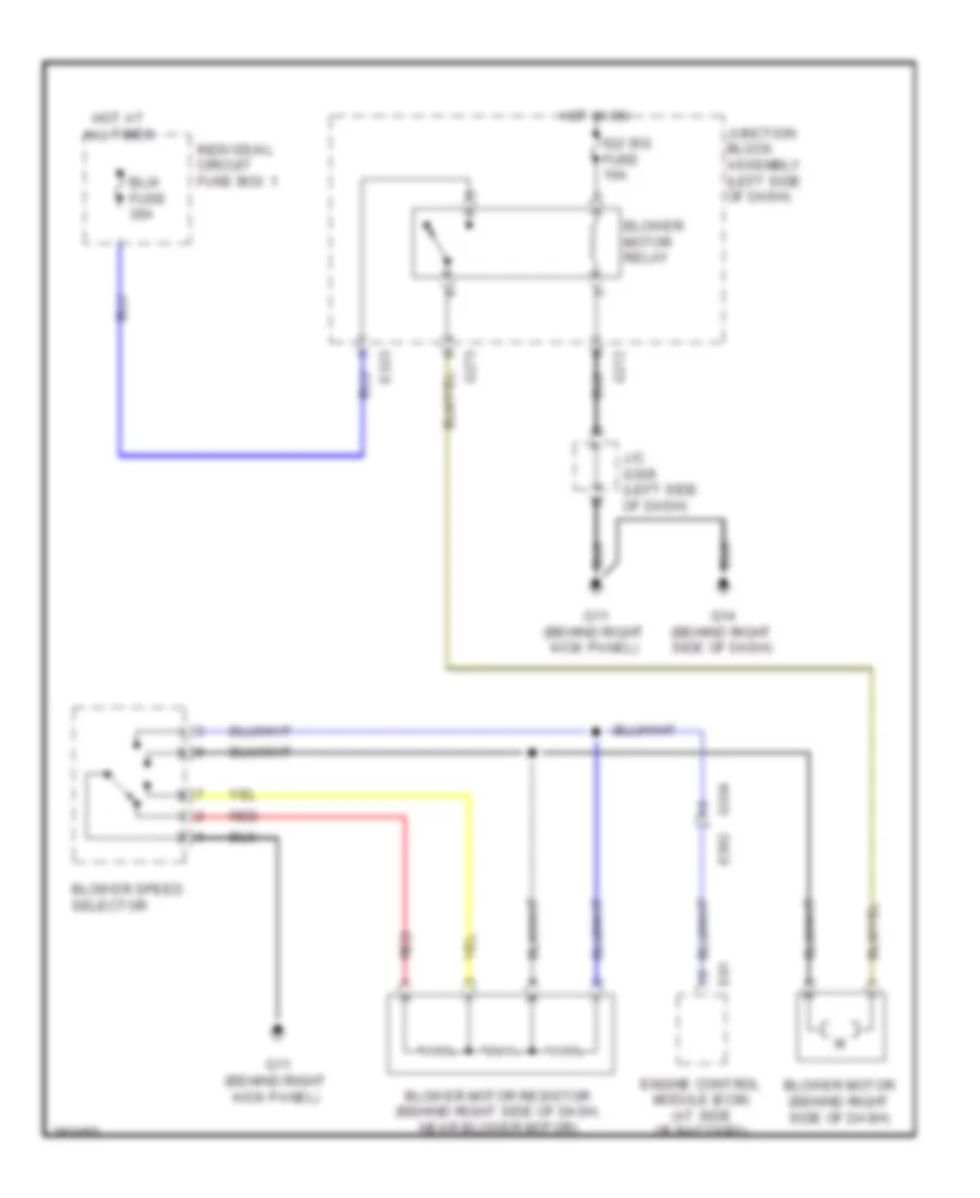
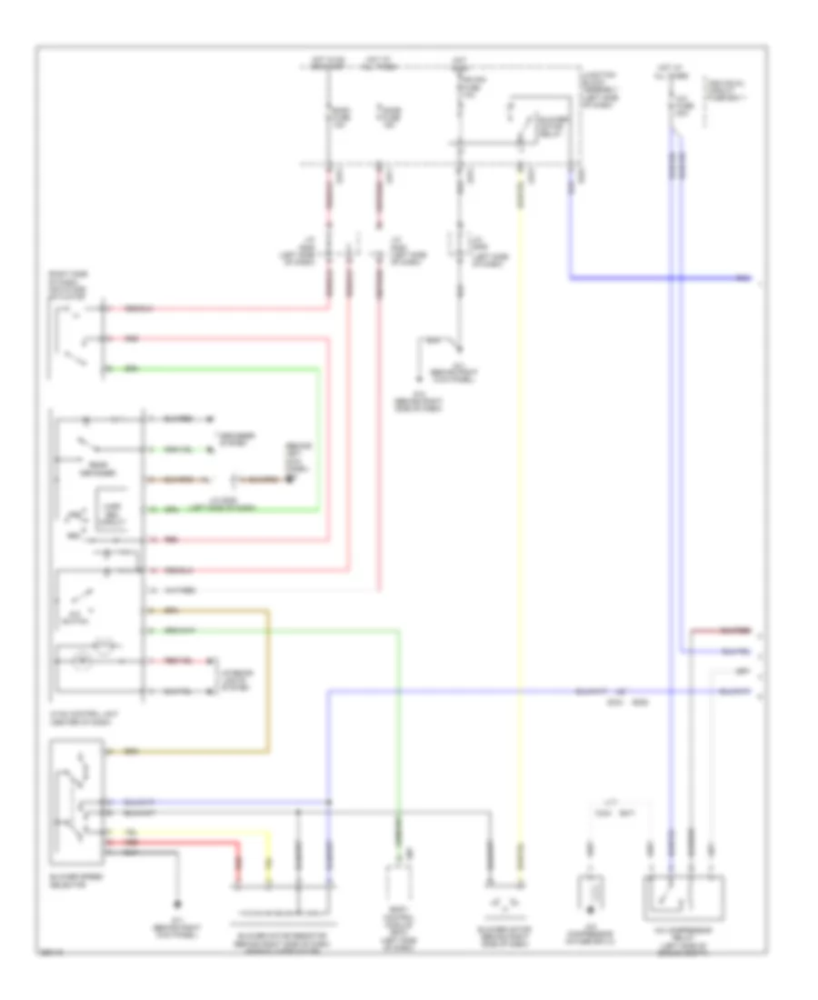
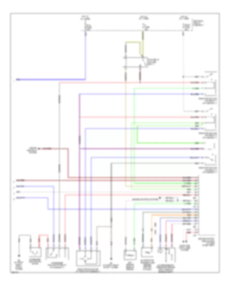
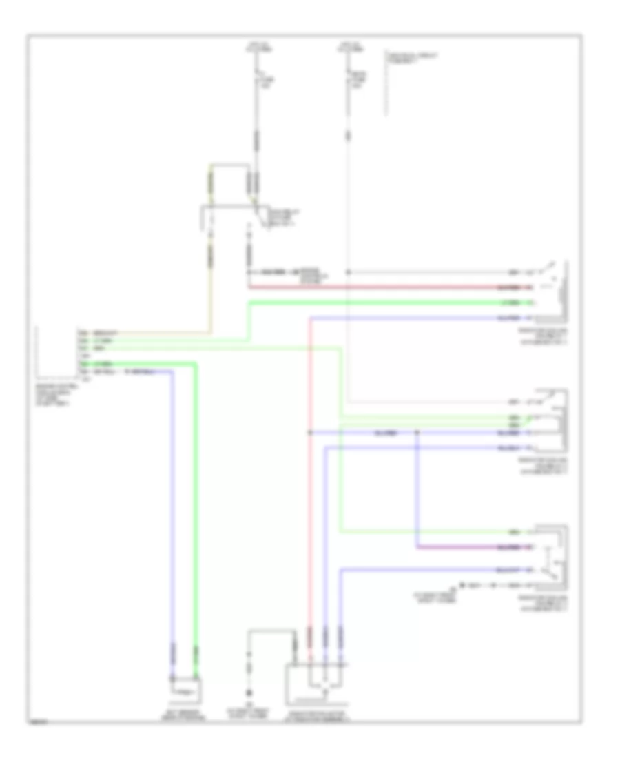
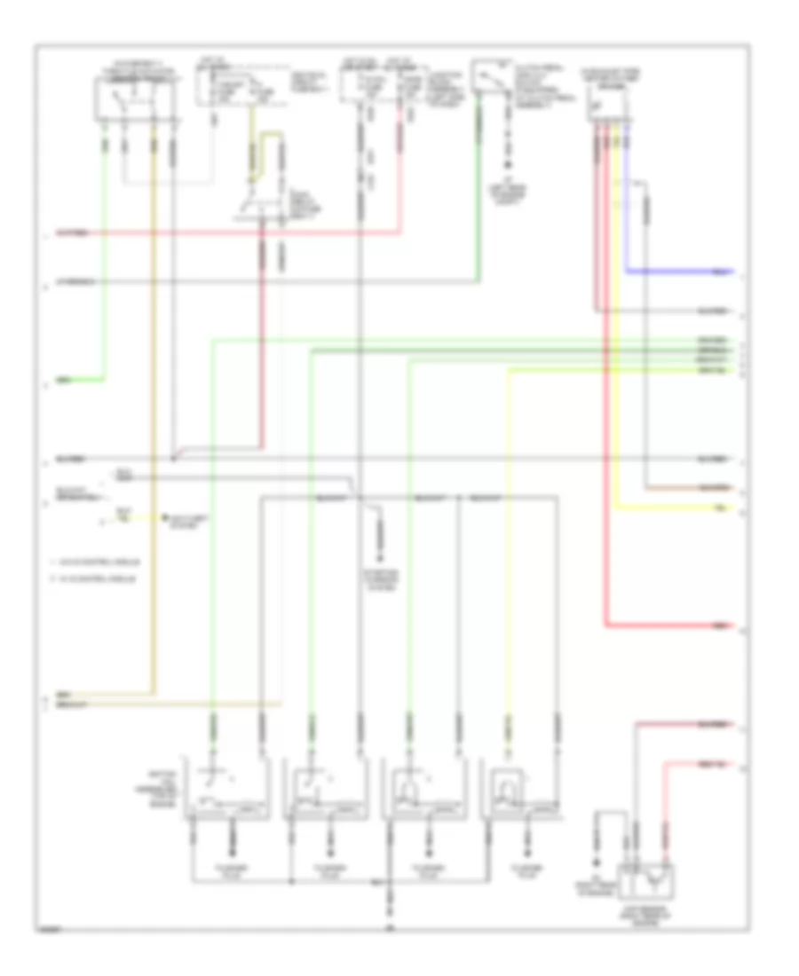
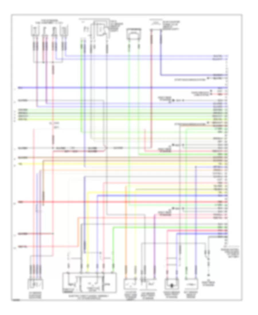
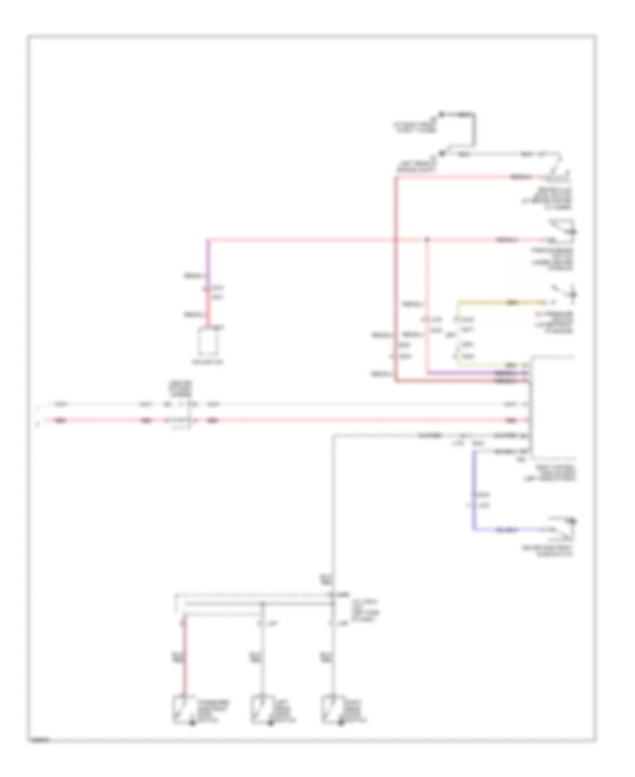
AIR CONDITIONING Automatic A/C Wiring Diagram (1 of 2) for Suzuki SX4 Crossover 2011 List of elements for Automatic A/C Wiring Diagram (1 of 2) for Suzuki SX4 Crossover 2011: 36 Acc fuse 15a Air flow control actuator (left side of dash) Air intake actuator (right side of dash) Back fuse 10a Blower motor (behind right side of dash) Blower motor relay Blower motor resistor (behind right side of dash, near blower motor) Blw fuse 30a Computer data lines system Defogger system Diode 1 (left side of dash) E323 Evaporator temperature sensor (center of dash) G11 (behind right kick panel) G13 (behind left kick panel) G14 (behind right side of dash) G272 G273 Hot at all times Hot in on Hot in on or acc Hot in on or start Hvac control module (center of dash) Ig2 sig fuse 10a Individual circuit fuse box 1 Inside air temperature sensor (left side of dash) Interior lights system J/c g306 (left side of dash) J/c g309 (left side of dash) J/c g310 (right side of dash) Junction block assembly (left side of dash) Pnk Power distribution system Red Sunload sensor (left side of dash) Temperature control actuator (left side of dash) Automatic A/C Wiring Diagram (2 of 2) for Suzuki SX4 Crossover 2011 List of elements for Automatic A/C Wiring Diagram (2 of 2) for Suzuki SX4 Crossover 2011: 31 (in fuse box 1) A/c compressor (left front of engine) A/c compressor relay (in fuse box 1) A/c fuse 20a A/c refrigerant pressure sensor (right rear of engine compt) Body control module (bcm) (left side of dash) C01 C343 Computer data lines system Condenser cooling fan motor Condenser cooling fan relay (in fuse box 1) E01 E371 E382 Ect sensor (rear of engine) Engine control module (ecm) (at side of battery) Engine controls system Fi fuse 15a G04 G05 G334 G9 (at right front strut tower) Hot at all times Individual circuit fuse box 1 Main relay (in fuse box 1) Radiator cooling fan relay 1 Radiator cooling fan relay 2 (in fuse box 1) Radiator cooling fan relay 3 (in fuse box 1) Radiator fan motor (at radiator assembly) Rdtr fuse 30a Red Heater Wiring Diagram for Suzuki SX4 Crossover 2011 List of elements for Heater Wiring Diagram for Suzuki SX4 Crossover 2011: 20 Blower motor (behind right side of dash) Blower motor relay Blower motor resistor (behind right side of dash, near blower motor) Blower speed selector Blw fuse 30a E01 E323 Engine control module (ecm) (at side of battery) G11 (behind right kick panel) G14 (behind right side of dash) G272 G273 G334 e382 Hot at all times Hot in on Ig2 sig fuse 10a Individual circuit fuse box 1 J/c g309 (left side of dash) Junction block assembly (left side of dash) Red Manual A/C Wiring Diagram (1 of 2) for Suzuki SX4 Crossover 2011 List of elements for Manual A/C Wiring Diagram (1 of 2) for Suzuki SX4 Crossover 2011: 45 (behind left kick panel) g13 (behind right kick panel) (left side of dash) (right side of dash) air intake actuator A/c compressor (in fuse box 2) A/c compressor relay (left side of engine compt) A/c fuse 20a A/c switch Back fuse 10a Blower motor (behind right side of dash) Blower motor relay Blower motor resistor (behind right side of dash, near blower motor) Blower speed selector Body control module (bcm) (left side of dash) C343 Defogger system Dome fuse 15a E323 E371 E382 Fre G05 G11 G11 (behind right kick panel) G14 (behind right side of dash) G271 G272 G273 G334 Harf rec circuit Hot at all times Hot in on Hot in on or start Hvac control unit (center of dash) Ig2 sig fuse 10a Individual circuit fuse box 1 Interior lights system J/c g306 (left side of dash) J/c g308 (left side of dash) J/c g309 J/c g309 (left side of dash) Junction block assembly (left side of dash) Rear defogger Rec Red Manual A/C Wiring Diagram (2 of 2) for Suzuki SX4 Crossover 2011 List of elements for Manual A/C Wiring Diagram (2 of 2) for Suzuki SX4 Crossover 2011: 24 A/c refrigerant pressure sensor (right rear of engine compt) Blw fuse 30a C01 Computer data lines system Condenser cooling fan motor Condenser cooling fan relay (in fuse box 1) E01 E382 Ect sensor (rear of engine) Engine control module (ecm) (at side of battery) Engine controls system Evaporator temperature sensor (center of dash) Fi fuse 15a G334 G9 (at right front strut tower) Hot at all times Individual circuit fuse box 1 Main relay (in fuse box 1) Radiator cooling fan relay 1 (in fuse box 1) Radiator cooling fan relay 2 (in fuse box 1) Radiator cooling fan relay 3 (in fuse box 1) Radiator fan motor (at radiator assembly) Rdtr fuse 30a Red
ANTI-LOCK BRAKES Anti-lock Brakes Wiring Diagram, with ESP for Suzuki SX4 Crossover 2011 List of elements for Anti-lock Brakes Wiring Diagram, with ESP for Suzuki SX4 Crossover 2011: 58 (in steering column assembly) steering angle sensor (left side of dash) Abs fuse 10a Abs ind Abs mot fuse 40a Abs sol fuse 30a Brake ind Brake light switch (top of brake pedal assembly) Can Combination meter Computer data lines system Cpu Dome fuse 15a E01 E323 E325 E381 E387 Engine control module (ecm) (at side of battery) Esp active ind Esp control module (right rear of engine compartment) Esp ind Esp off switch Exterior lights system G13 (behind left kick panel) G16 (under front passenger's seat) G17 (under driver's seat) G21 (hatch back: base of left "d" pillar) (sedan: at left rear wheel well) G271 G272 G333 G341 G8 (at right front strut tower) High Hot at all times Hot in on or start Ig 1 sig fuse 10a Individual circuit fuse box 1 Instrument cluster system Interior lights system J/c g308 (left side of dash) J/c g309 J/c g311 (center of dash) J/c l348 (left kick panel) Junction block assembly (left side of dash) L315 L371 L374 Left front wheel speed sensor (at left front wheel hub assembly) Left rear wheel speed sensor (at left rear wheel hub assembly) Low Mtr fuse 10a Red Right front wheel speed sensor (at right front wheel hub assembly) Right rear wheel speed sensor (at right rear wheel hub assembly) Stop fuse 15a Tcss off ind Yaw/g sensor Anti-lock Brakes Wiring Diagram, without ESP for Suzuki SX4 Crossover 2011 List of elements for Anti-lock Brakes Wiring Diagram, without ESP for Suzuki SX4 Crossover 2011: 38 Abs control module (right rear of engine compt) Abs fuse 10a Abs ind Abs mot fuse 40a Abs sol fuse 30a Body control module (bcm) (left side of dash) Brake ind Brake light switch (top of brake pedal assembly) Can Combination meter Computer data lines system Cpu E01 E323 E325 E387 Engine control module (ecm) (at side of battery) Exterior lights system G sensor (4wd model) (under center console) G05 G271 G8 (at right front strut tower) High Hot at all times Hot in on or start Individual circuit fuse box 1 J/c g311 (center of dash) Junction block assembly (left side of dash) L315 L371 Left front wheel speed sensor (at left front wheel hub assembly) Left rear wheel speed sensor (at left rear wheel hub assembly) Low Mtr fuse 10a Red Right front wheel speed sensor (at right front wheel hub assembly) Right rear wheel speed sensor (at right rear wheel hub assembly) Stop fuse 10a
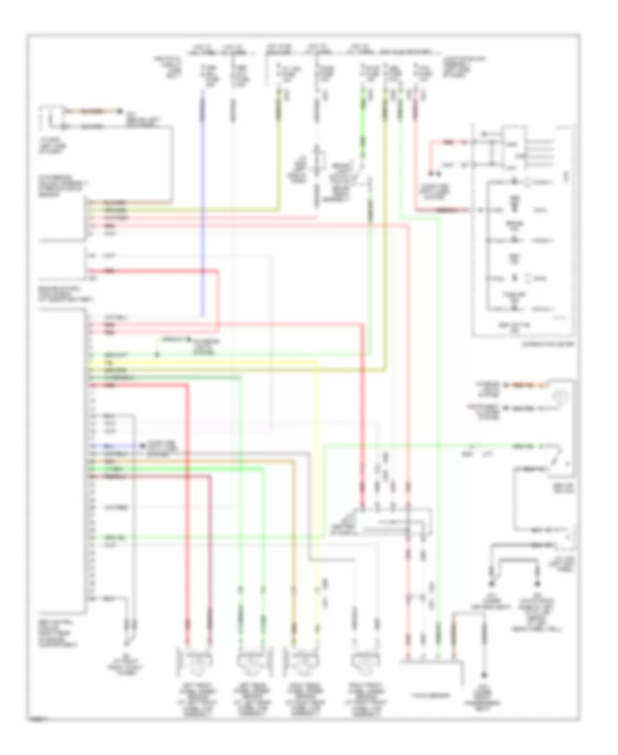
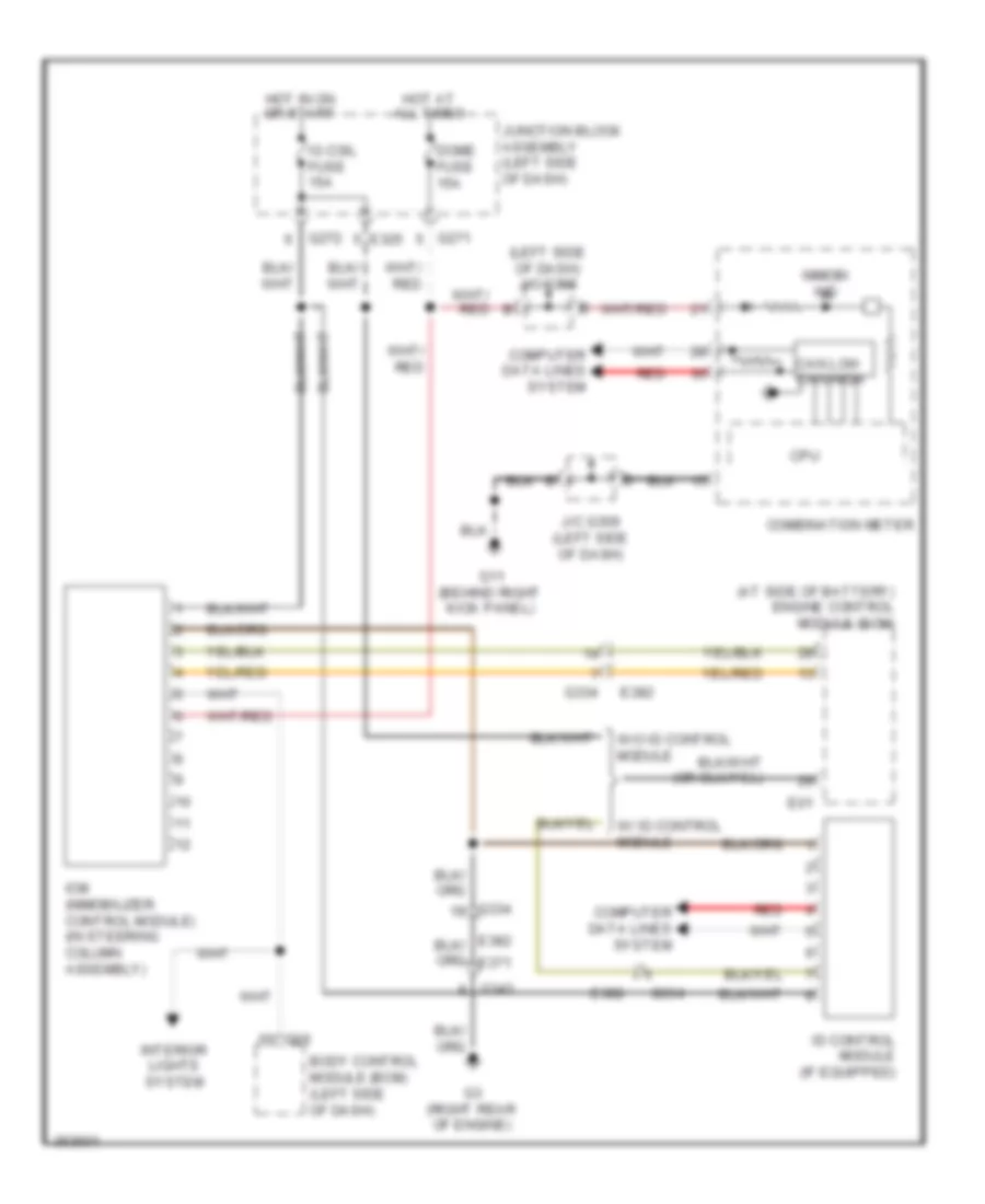
ANTI-THEFT Forced Entry Wiring Diagram for Suzuki SX4 Crossover 2011 List of elements for Forced Entry Wiring Diagram for Suzuki SX4 Crossover 2011: 76 (at left rear wheel well) (behind right kick panel) g11 (under driver's (under driver's seat) Body control module (bcm) (left side of dash) Can Combination meter Computer data lines system Cpu D/l fuse 20a Dome fuse 15a Door ind Driver side front door switch (at left "b" pillar) Driver side front power door lock switch Driver side power door lock main switch Front passenger side door switch (at right "b" pillar) Front passenger side power door lock motor G04 G05 G06 G17 G17 (under driver's seat) G21 G21 (base of left "d" pillar) G271 G341 G343 G352 Hatch- back Hazard switch (security light) Headlights system Horns system Hot at all times Hot in on or start If equipped J/c g308 (left side of dash) J/c g309 (left side of dash) J/c l346 & l347 (left side of dash) J215 J216 J217 J218 Junction block assembly (left side of dash) Keyless entry receiver (behind right end of dash) L346 L347 L374 L376 L379 L380 L381 L382 L390 L394 L402 Left rear door switch Left rear power door lock motor Lock M152 Mtr fuse 10a O231 Off Passenger side power door lock sub switch (if equipped) Pnk Rear end power door lock solenoid (hatchback) Rear end power door lock switch (hatchback) Red Regulator voltage Right rear door switch Right rear power door lock motor Seat) Security option Sedan Tpms receiver (under center console, at hand brake assembly) Trunk room lock solenoid Un- lock Immobilizer Wiring Diagram for Suzuki SX4 Crossover 2011 List of elements for Immobilizer Wiring Diagram for Suzuki SX4 Crossover 2011: 30 (at side of battery) engine control module (ecm) (left side of dash) j/c g308 Body control module (bcm) (left side of dash) Can low can high Combination meter Computer data lines system Cpu Dome fuse 15a E01 E325 E382 G06 G11 (behind right kick panel) G271 G272 G3 (right rear of engine) G334 G343 Hot at all times Hot in on or start Icm (immobilizer control module) (in steering column assembly) Id control module (if equipped) Ig coil fuse 15a Immobi ind Interior lights system J/c g309 (left side of dash) Junction block assembly (left side of dash) Red W/ id control module W/o id control module
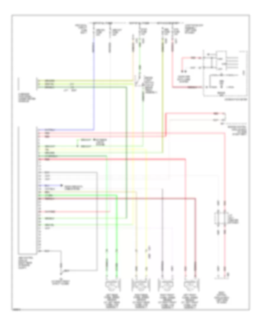
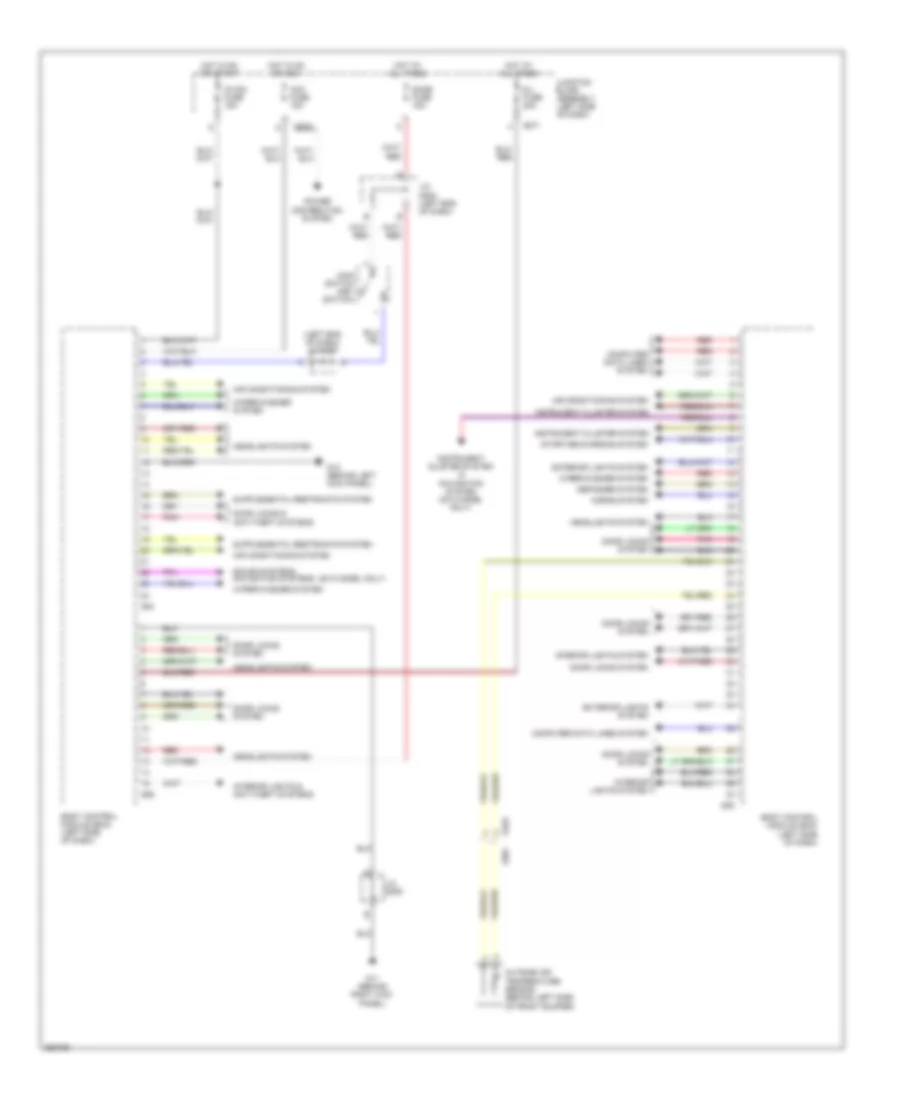
BODY CONTROL MODULES Body Control Modules Wiring Diagram for Suzuki SX4 Crossover 2011 List of elements for Body Control Modules Wiring Diagram for Suzuki SX4 Crossover 2011: 42 (2013 model only) (left end of dash) j/c g307 Acc fuse 15a Air conditioning system Body control module (bcm) (left side of dash) Computer data lines system D/l fuse 20a Defogger system Dome fuse 15a Door locks & anti-theft systems Door locks system E381 Exterior lights system G04 G05 G06 G11 (behind right kick panel) G12 (behind left kick panel) G271 G272 G333 Headlights system Horns system Hot at all times Hot in on or acc Hot in on or start Ig coil fuse 15a Instrument cluster system Instrument cluster system & navigation system (2013 model only) Interior lights & anti-theft systems Interior lights system J/c g308 (left end of dash) J/c g309 Junction block assembly (left side of dash) Main switch (key switch) Outside air temperature sensor (behind left side of front bumper) Pnk Power distribution system Red Sound systems navigation systems Starting/charging system Wiper/washer system
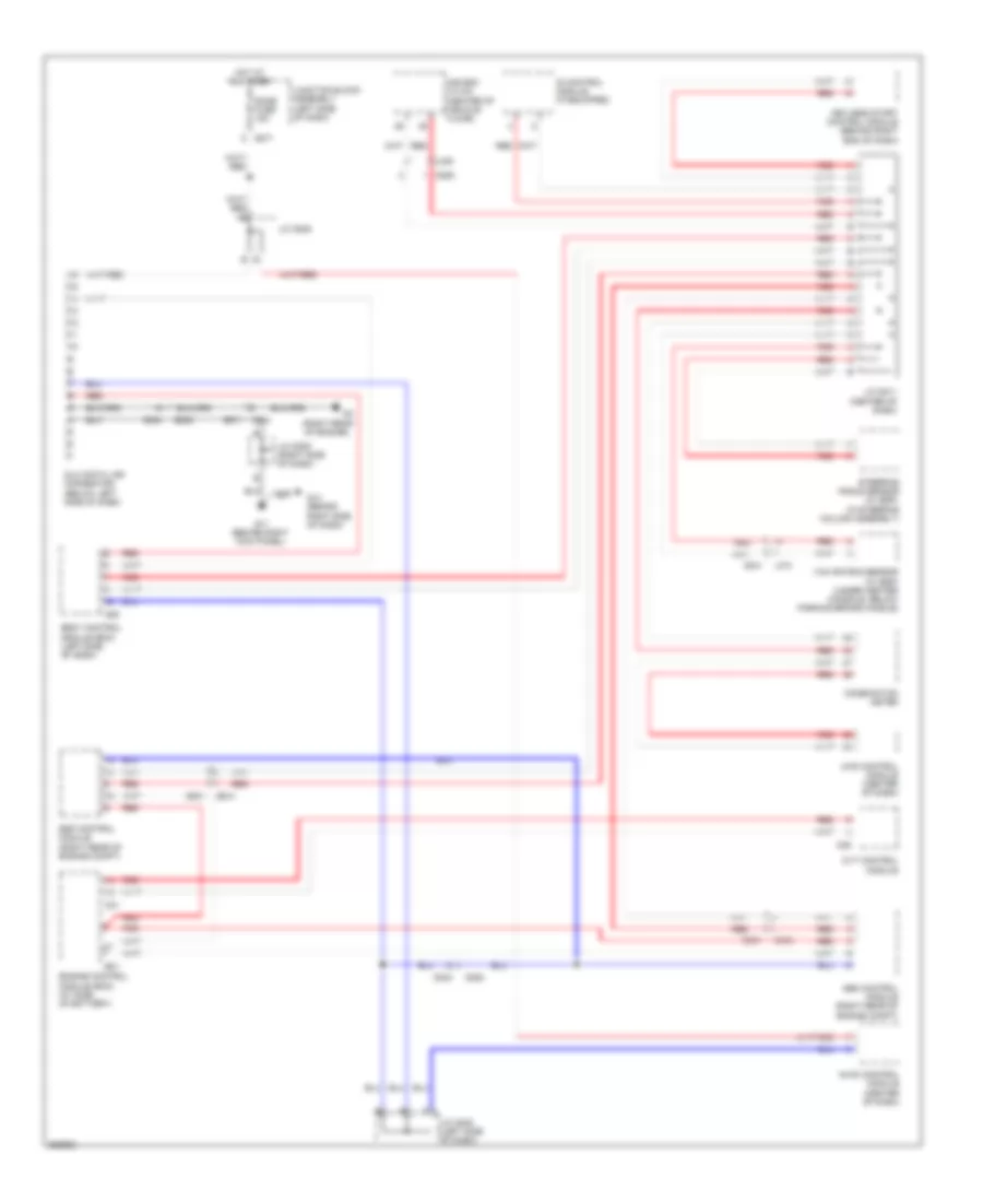
COMPUTER DATA LINES Computer Data Lines Wiring Diagram for Suzuki SX4 Crossover 2011 List of elements for Computer Data Lines Wiring Diagram for Suzuki SX4 Crossover 2011: 42 (in steering column assembly) (right rear of engine) 4wd control module (center of dash) A/b sdm (10 ch) (center of vehicle floor) Abs control module (right rear of engine compt) Body control module (bcm) (left side of dash) C01 C09 C343 Combination meter Cvt control module Dlc (data link connector) (below left side of dash) Dome fuse 15a E01 E371 E381 E382 Engine control module (ecm) (at side of battery) Esp control module (right rear of engine compt) G05 G11 (behind right kick panel) G14 (behind right side of dash) G271 G333 G334 G341 G350 G382 Hot at all times Hvac control module (center of dash) Id control module (if equipped) J/c g308 J/c g308 (left side of dash) J/c g309 (right side of dash) J/c g311 (center of dash) Junction block assembly (left side of dash) Keyless start control module (behind right end of dash) L374 L400 Red Steering angle sensor (w/ esp) Yaw rate/g sensor (w/ esp) (under center console, below parking brake handle)
COOLING FAN Cooling Fan Wiring Diagram for Suzuki SX4 Crossover 2011 List of elements for Cooling Fan Wiring Diagram for Suzuki SX4 Crossover 2011: 15 C01 E01 Ect sensor (rear of engine) Engine control module (ecm) (at side of battery) Engine controls system Fi fuse 15a G9 (at right front strut tower) Hot at all times Individual circuit fuse box 1 Main relay (in fuse box no 1) Radiator cooling fan relay 1 (in fuse box no 1) Radiator cooling fan relay 2 (in fuse box no 1) Radiator cooling fan relay 3 (in fuse box no 1) Radiator fan motor (at radiator assembly) Rdtr fuse 30a
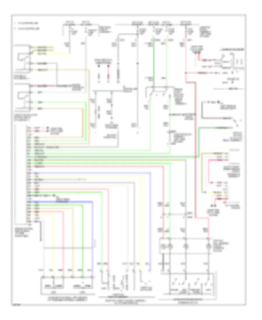
CRUISE CONTROL Cruise Control Wiring Diagram for Suzuki SX4 Crossover 2011 List of elements for Cruise Control Wiring Diagram for Suzuki SX4 Crossover 2011: 60 Acceleration pedal (app) sensor (at accelerator pedal assembly) Automatic cruise switch Brake light switch (top of brake pedal assembly) C01 C09 C10 Can hi Can lo Cancel Close Combination meter Computer data lines system Contact coil assembly (top of steering column) Cpp cut switch (at clutch pedal assembly) Cpu Cruise ind Cvt control module E01 E323 E325 E382 E383 Electric throttle body assembly (at intake manifold) Engine control module (ecm) (at side of battery) Engine controls system Exterior lights system Fi fuse 15a G271 G272 G3 (right rear of engine) G334 G335 G7 (left rear of engine compt) Hot at all times Hot in on or start Id controller module Ig coil fuse 15a Ig1 sig fuse 10a Individual circuit fuse box 1 Junction block assembly (left side of dash) Main Main relay (in fuse box 1) Mtr fuse 10a Nca Open Output shaft speed sensor (top of transaxle assembly) Pnk Red Resume/ accel Set ind Set/ coast Steering switch Stop fuse 10a Sub Thr mot fuse 15a Throttle actuator Throttle actuator control relay (in fuse box 1) Throttle position sensor W/ id controller W/o id controller
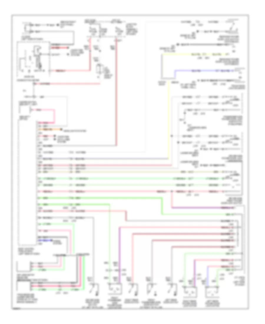
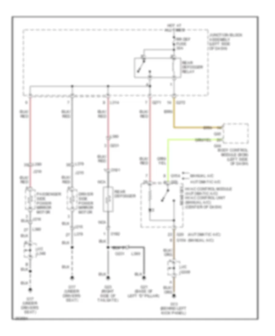
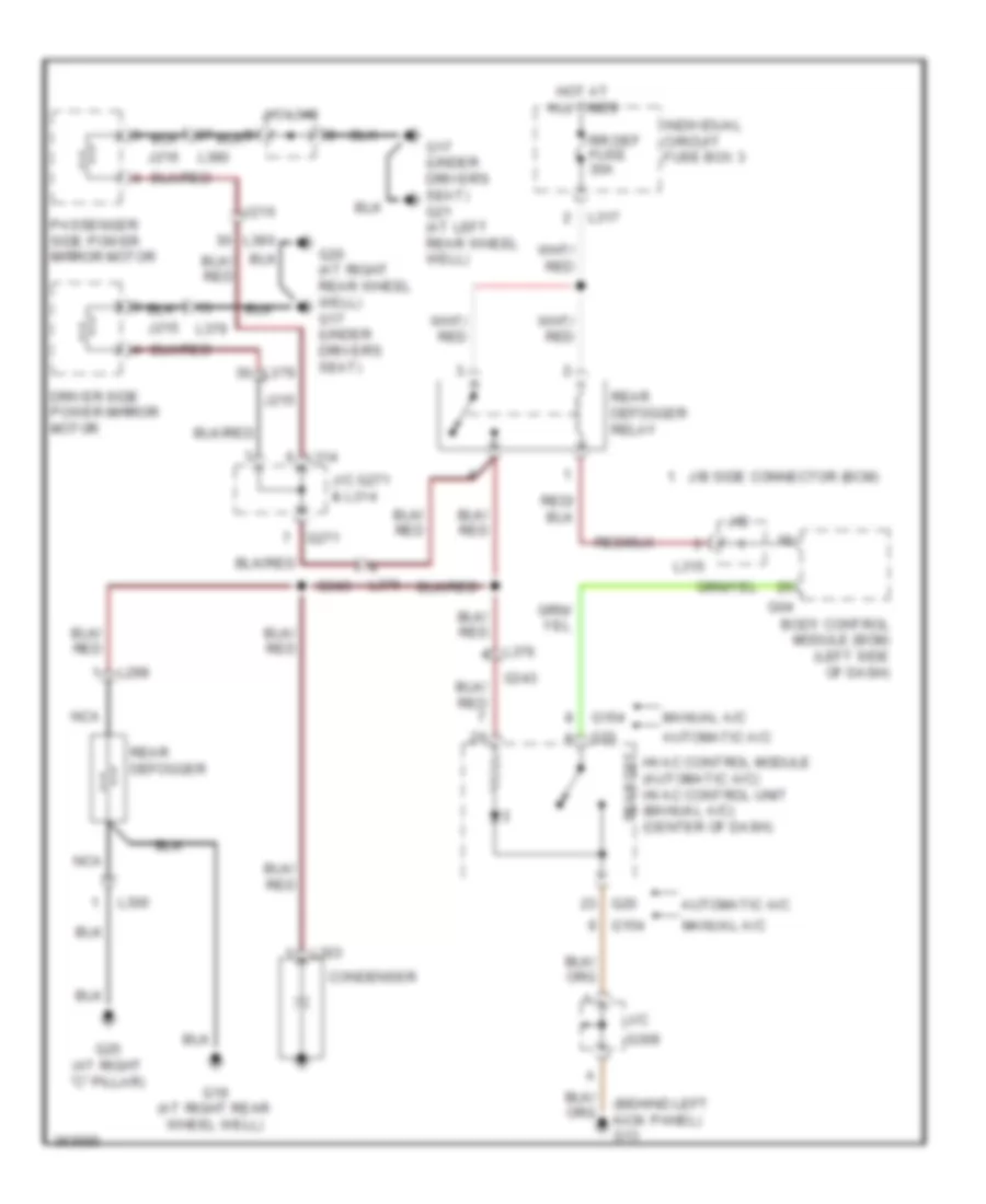
DEFOGGERS Defoggers Wiring Diagram, Hatchback for Suzuki SX4 Crossover 2011 List of elements for Defoggers Wiring Diagram, Hatchback for Suzuki SX4 Crossover 2011: 37 (automatic a/c) (manual a/c) Automatic a/c Body control module (bcm) (left side of dash) Driver side power mirror motor G04 G05 G13 (behind left kick panel) G154 G17 (under driver's seat) G20 G21 (base of left "d" pillar) G23 (right side of tailgate) G271 G272 G309 Hot at all times Hvac control module (automatic a/c) hvac control unit (manual a/c) (center of dash) J/c J/c l348 J215 J216 Junction block assembly (left side of dash) L314 L379 L380 L390 Manual a/c Nca O181 O182 O231 Passenger side power mirror motor Rear def Rear defogger Rear defogger relay Rr def fuse 30a Defoggers Wiring Diagram, Sedan for Suzuki SX4 Crossover 2011 List of elements for Defoggers Wiring Diagram, Sedan for Suzuki SX4 Crossover 2011: 41 (behind left kick panel) g13 Automatic a/c Body control module (bcm) (left side of dash) Condenser Driver side power mirror motor G04 G154 G17 (under driver's seat) g21 (at left rear wheel well) G19 (at right rear wheel well) G20 G20 (at right rear wheel well) g17 (under driver's seat) G25 (at right "c" pillar) G271 G309 G343 Hot at all times Hvac control module (automatic a/c) hvac control unit (manual a/c) (center of dash) Individual circuit fuse box 3 J/b J/b side connector (bcm) J/c J/c g271 & l314 J/c l348 J215 J216 L299 L300 L303 L314 L315 L317 L376 L379 L380 Manual a/c Nca Passenger side power mirror motor Rear def Rear defogger Rear defogger relay Rr def fuse 30a
ENGINE PERFORMANCE
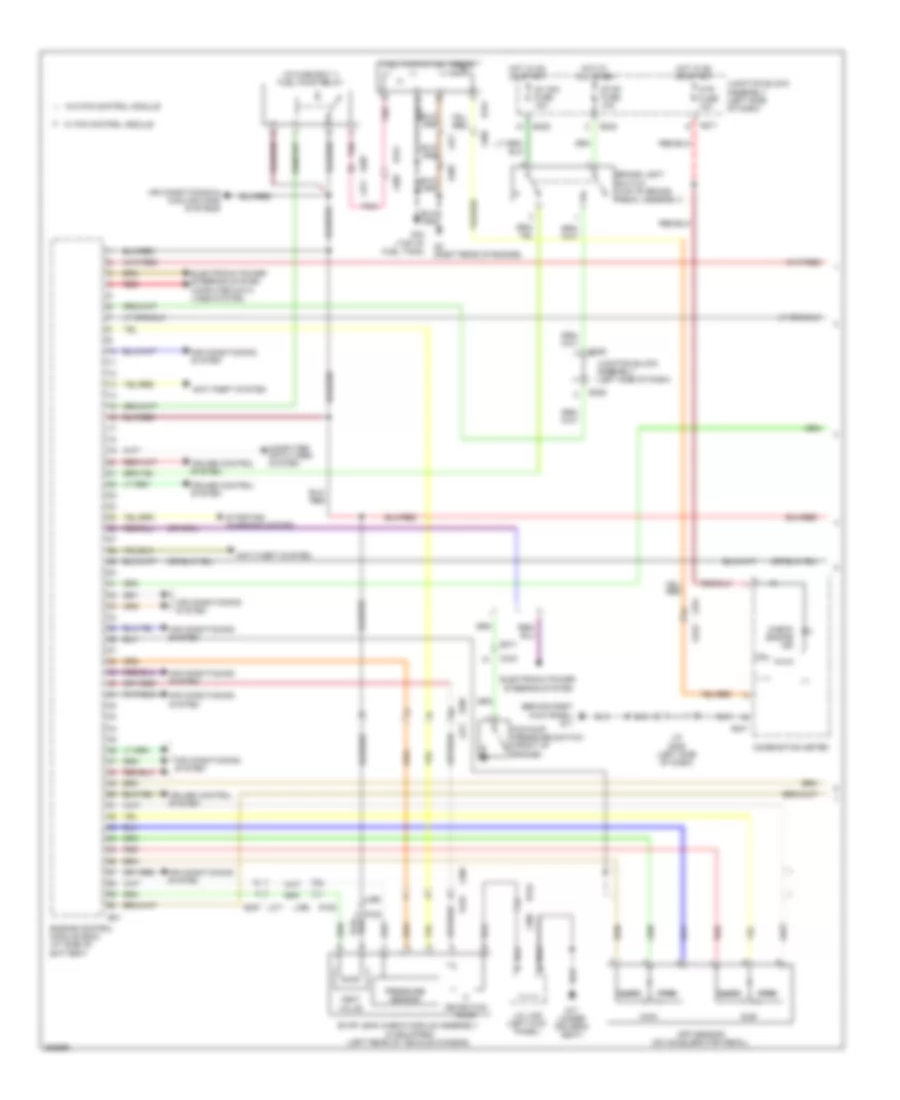
2.0L 2.0L, Engine Performance Wiring Diagram (1 of 3) for Suzuki SX4 Crossover 2011 List of elements for 2.0L, Engine Performance Wiring Diagram (1 of 3) for Suzuki SX4 Crossover 2011: 56 (behind right kick panel) g11 (in fuse box 1) fuel pump relay Air conditioning & cooling fans systems Air conditioning system Anti-theft system App sensor (on accelerator pedal) Brake light switch (top of brake pedal assembly) C343 Check engine ind Close Combination meter Computer data lines system Cpu Cruise control system Detection pump E01 E323 E325 E371 E387 Electronic power steering system Electronic power steering system computer data lines system Engine control module (ecm) (at side of battery) Evap leak check module assembly (if equipped) (left rear of vehicle chassis) Fuel pump & fuel gauge G17 (under driver's seat) G24 (top of fuel tank) G241 G271 G3 (right rear of engine) G343 Hot at all times Hot in on or start Ig1 sig fuse 10a J/c g309 (left side of dash) J/c l348 (left kick panel) Junction block assembly (left side of dash) L371 L376 L389 L396 Main Mtr fuse 10a Open P/s pump pressure switch (front of engine) Pnk Pressure sensor R151 R152 Red Starting/ charging system Stop fuse 10a Sub Vent valve W/ p/s control module W/o p/s control module 2.0L, Engine Performance Wiring Diagram (2 of 3) for Suzuki SX4 Crossover 2011 List of elements for 2.0L, Engine Performance Wiring Diagram (2 of 3) for Suzuki SX4 Crossover 2011: 27 (in exhaust pipe) heated oxygen sensor (in fuse box 1) throttle actuator control relay Anti-theft system C343 Clutch pedal (cpp) cut switch (if equipped) (at clutch pedal assembly) Cmp sensor (right rear of engine) Dome fuse 15a E323 E325 E371 Fi fuse 15a G3 (right rear of engine) G7 (left rear of engine compt) Hot at all times Hot in on or start Ig coil fuse 15a Ignition coil assemblies (top of engine) Individual circuit fuse box 1 Junction block assembly (left side of dash) Main relay (in fuse box 1) Nca Red Starting/ charging system Thr mot fuse 15a To spark plug W/ id control module W/o id control module 2.0L, Engine Performance Wiring Diagram (3 of 3) for Suzuki SX4 Crossover 2011 List of elements for 2.0L, Engine Performance Wiring Diagram (3 of 3) for Suzuki SX4 Crossover 2011: 26 (right rear of engine) g3 (top of engine) fuel injectors 1, 2, 3 & 4 A/f sensor (in exhaust down pipe) C01 C343 Ckp sensor (right front of engine) Close Computer data lines system E371 Ect sensor (rear of engine) Electric throttle body assembly (at intake manifold) Engine control module (ecm) (at side of battery) Evap canister purge valve (rear of engine compt) G3 (right rear of engine) Knock sensor (right front of engine) Maf & iat sensor (rear of engine compt) Main Open Pnk Red Starting/charging system Sub Throttle motor Throttle sensor Vim motor (right side of engine compt) Vvt solenoid
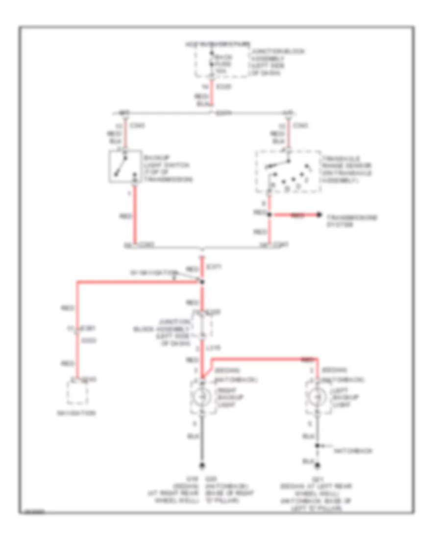
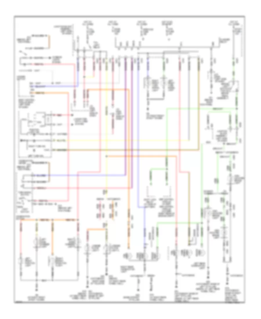
EXTERIOR LIGHTS Backup Lamps Wiring Diagram for Suzuki SX4 Crossover 2011 List of elements for Backup Lamps Wiring Diagram for Suzuki SX4 Crossover 2011: 26 (hatchback) (sedan) (sedan) (at right rear wheel well) A/t Back fuse 10a Backup light switch (top of transmission) C343 E325 E371 E381 G19 g20 (hatchback) (base of right "d" pillar) G21 (sedan: at left rear wheel well) (hatchback: base of left "d" pillar) G243 G333 Hatchback Hot in on or start Junction block assembly (left side of dash) L315 Left backup light M/t Navigation Red Right backup light Transaxle range sensor (on transaxle assembly) Transmissions system W/ navigation Exterior Lamps Wiring Diagram for Suzuki SX4 Crossover 2011 List of elements for Exterior Lamps Wiring Diagram for Suzuki SX4 Crossover 2011: 91 (hatchback) (base of left "d" pillar) Body control module (bcm) (left side of dash) Brake light switch (top of brake pedal assembly) Can Combination meter Combination switch Computer data lines system Cpu Dome fuse 15a E01 E323 E325 Ecm Esp control module (w/ esp) abs control module (w/o esp) (right rear of engine compt) Flasher relay G04 G05 G11 (behind right kick panel) G13 (behind left kick panel) G19 (at right rear wheel well) G19 (hatchback: base of right "d" pillar) (sedan: at right rear wheel well) G19 (sedan) (at right rear wheel well) G20 (base of right "d" pillar) G20 (hatchback: base of left "d" pillar) (sedan: at left rear wheel well) G21 (hatchback: base of left "d" pillar) (sedan: at left rear wheel well) G21 g19 (sedan) (at right rear wheel well) G23 (hatchback) (right side of tailgate) G271 G272 G341 G9 (at right front strut tower) Gnd Hatchback Haz Hazard switch Head High mounted brake light Horn-haz fuse 15a Hot at all times Hot in on or start Interior lights system J/c g306 (left side of dash) J/c g308 (left side of dash) J/c g309 (left side of dash) Junction block assembly (left side of dash) L314 L315 L374 L390 L393 L394 Left front position light Left front turn signal light Left rear combination light Left side marker light Left turn ind License plate light 1 License plate light 2 Light brake Light signal Light signal turn Light switch Light tail Low Lp-l Lp-r M152 Mtr fuse 10a O231 O233 Off On back window On trunk Position light ind Red Red/ Right front position light Right front turn signal light Right rear combination light Right side marker light Right turn ind Sedan Shift lock relay (at side of battery) Stop fuse 10a Sw-l Sw-r Tail Tail fuse 10a Tail light relay Turn Turn signal switch
GROUND DISTRIBUTION
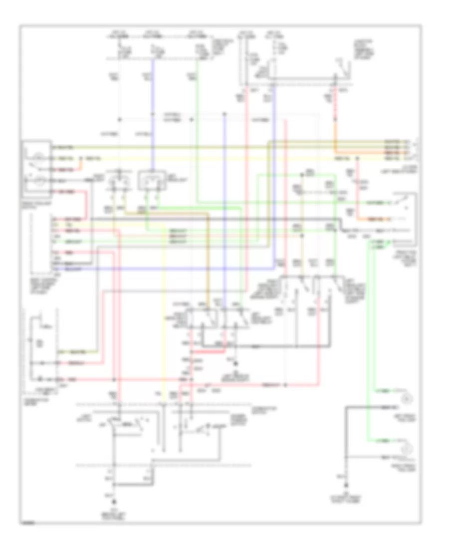
HEADLIGHTS Headlights Wiring Diagram for Suzuki SX4 Crossover 2011 List of elements for Headlights Wiring Diagram for Suzuki SX4 Crossover 2011: 47 Body control module (bcm) (left side of dash) Combination meter Combination switch Cpu Dimmer/ passing switch Drl ind E334 E381 E382 Flash Fr fog fuse 20a Front fog light relay (in fuse box 1) Front foglamp switch G04 G05 G06 G13 (behind left kick panel) G241 G271 G272 G333 G381 G6 (left rear of engine compt) G9 (at right front strut tower) H/l l fuse 15a H/l r fuse 15a Head High beam ind Hot at all times Individual circuit fuse box 1 J/c g306 (left side of dash) Junction block assembly (left side of dash) Left front fog lamp Left headlight Left headlight high relay Left headlight low relay (left side of engine compt) Light switch Mtr fuse 10a Off Red Right front fog lamp Right headlight Right headlight high relay Right headlight low relay (left side of engine compt) Tail Tail fuse 10a Tail light relay
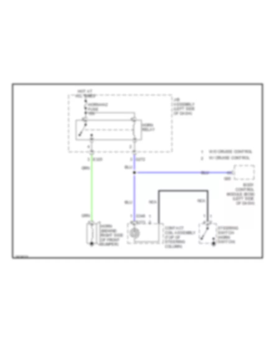
HORN Horn Wiring Diagram for Suzuki SX4 Crossover 2011 List of elements for Horn Wiring Diagram for Suzuki SX4 Crossover 2011: 16 Body control module (bcm) (left side of dash) Contact coil assembly (top of steering column) E325 G05 G272 G346 Horn (behind right side of front bumper) Horn relay Horn-haz fuse 15a Hot at all times J/b assembly (left side of dash) Nca S171 Steering switch (horn switch) W/ cruise control W/o cruise control
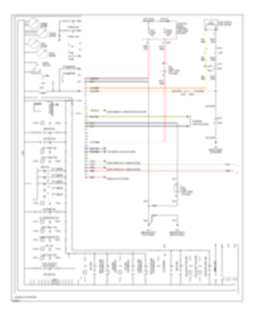
INSTRUMENT CLUSTER Instrument Cluster Wiring Diagram (1 of 2) for Suzuki SX4 Crossover 2011 List of elements for Instrument Cluster Wiring Diagram (1 of 2) for Suzuki SX4 Crossover 2011: 69 4wd auto ind (4wd model) 4wd lock ind (4wd model) Abs ind (abs model) Air bag ind Brake ind Buzzer C343 Can Charge ind Check engine ind Combination meter Computer data lines system Cool temp ind Cpu Cruise ind Cvt model Dome fuse 15a Door ind Drl ind E371 E382 E387 Eps active ind (eps model) Eps ind Eps ind (eps model) Exterior lights system Fuel meter Fuel pump & fuel gauge G11 (behind right kick panel) G14 (behind right side of dash) G271 G3 (right rear of engine) G334 G343 Headlights system Hi beam ind High Hot at all times Hot in on or start Hot temp ind If equipped Immobi ind Interior J/c g308 (left side of dash) J/c g309 (left side of dash) Junction block assembly (left side of dash) Key start red ind L371 L376 L389 Lcd Lights system Low Low fuel ind Mode switch Mtr fuse 10a Oil pressure ind Position light ind R151 Red Seat belt ind Set ind Speed meter Tacho meter Tcss off ind (eps model) Temp meter Turn-l ind Turn-r ind Voltage regulator Instrument Cluster Wiring Diagram (2 of 2) for Suzuki SX4 Crossover 2011 List of elements for Instrument Cluster Wiring Diagram (2 of 2) for Suzuki SX4 Crossover 2011: 26 (center of dash) j/c g311 Body control module (bcm) (left side of dash) Brake fluid level switch (at brake master cylinder) C343 C374 Driver side front door switch E371 E381 F l346 G05 G243 G333 G341 G343 G7 (left rear of engine compt) G9 (at right front strut tower) J/c l346 & l347 (left side of dash) L347 d L376 Left rear door switch Navigation Oil pressure switch (lower front of engine) Parking brake switch (under center console) Passenger side front door switch Red Right rear door switch
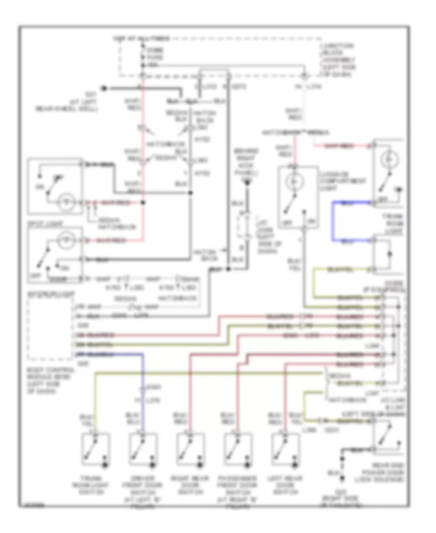
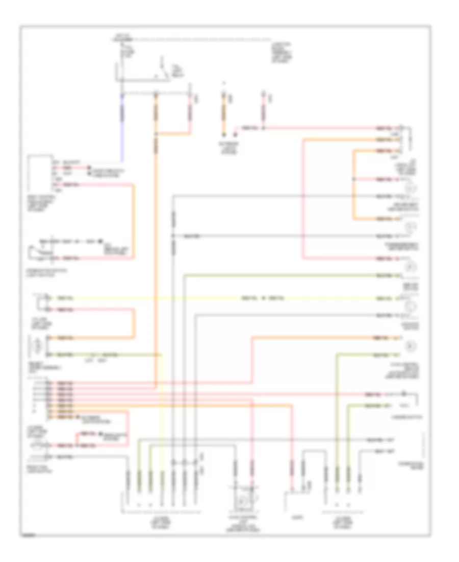
INTERIOR LIGHTS Courtesy Lamps Wiring Diagram for Suzuki SX4 Crossover 2011 List of elements for Courtesy Lamps Wiring Diagram for Suzuki SX4 Crossover 2011: 42 (at left rear wheel well) (behind right kick panel) g11 Back Body control module (bcm) (left side of dash) Diode (if equipped) Dome fuse 15a Door Driver front door switch (at left "b" pillar) G05 G06 G21 G23 (right side of tailgate) G272 G343 Hatch- Hatch- back Hatchback Hot at all times Interior light J/c g309 (left side of dash) J/c l346 & l347 (left side of dash) Junction block assembly (left side of dash) K152 L312 L314 L346 L347 L376 L383 L390 Left rear door switch Luggage compartment light O231 Off Passenger front door switch (at right "b" pillar) Rear end power door lock solenoid Right rear door switch Sedan Sedan hatchback Spot light Trunk room light Trunk room light switch Instrument Illumination Wiring Diagram for Suzuki SX4 Crossover 2011 List of elements for Instrument Illumination Wiring Diagram for Suzuki SX4 Crossover 2011: 38 2wd/4wd switch Audio Body control module (bcm) (left side of dash) Combination meter Combination switch (light switch) Computer data lines system Driver seat heater switch E325 Esp off switch Exterior lights system Front fog lamp switch G04 G05 G13 (behind left kick panel) G248 G272 G341 Hazard switch Head Headlights system Hot at all times Hvac control module (automatic a/c) (center of dash) Hvac control unit (manual a/c) (center of dash) J/c g306 (left side of dash) J/c l346 & l347 (left side of dash) J/c l346 (left side of dash) Junction block assembly (left side of dash) L314 L346 L347 L374 Off Passenger seat heater switch Red Select lever assembly (a/t) Tail Tail fuse 10a Tail light relay
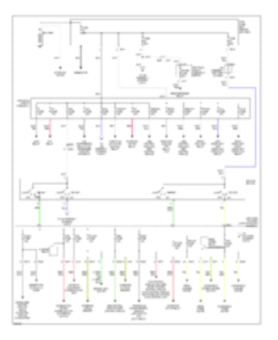
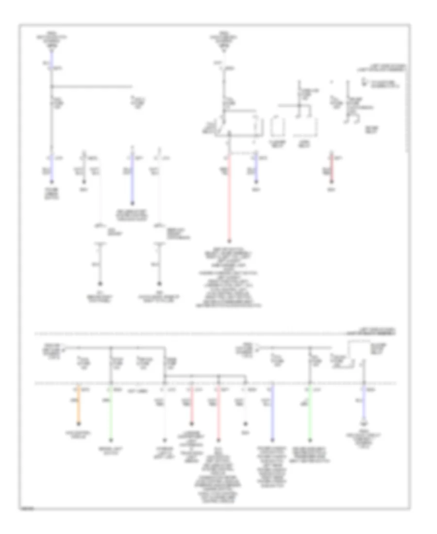
POWER DISTRIBUTION Power Distribution Wiring Diagram (1 of 2) for Suzuki SX4 Crossover 2011 List of elements for Power Distribution Wiring Diagram (1 of 2) for Suzuki SX4 Crossover 2011: 83 (left side of dash) junction block assembly 4wd control module, keyless start system control module, hvac control module, air intake actuator & hvac control unit A/b fuse 15a A/b sdm & occupancy classification ecm A/c compressor relay & a/c condenser cooling fan relay A/c fuse 20a Abs control module & esp control module Abs fuse 10a Abs mot fuse 40a Abs sol fuse 30a Acc At fuse 15a Back fuse 10a Battery Blw fuse 30a Brake light switch Combination meter, hazard switch & steering switch Cvt relay E311 E312 E323 E324 E325 E382 E387 Fi fuse 15a Flasher relay Fr fog fuse 20a Front fog light relay Fuse 50a Fuse 80a G sensor & yaw/g sensor G271 G272 G273 G334 Generator Generator, ig coils 1-4 & ecm H/l l fuse 15a H/l r fuse 15a Ig coil fuse 15a Ig1 sig fuse 10a Ign fuse 50a Ignition switch Immobilizer control module, bcm & id control module (if equipped) Individual circuit fuse box 1 Individual circuit fuse box 3 (sedan) J/b assembly (left side of dash) L312 L313 L315 L317 L371 Left headlight, left headlight high & low relay Lock Main fuse box (behind battery) Main relay Mtr fuse 10a Radiator cooling fan relay 1 & 2 Rdtr fuse 30a Rear defogger relay Rear washer motor Rear wiper motor Rear wiper relay (hatchback) Red Right headlight, right headlight high & low relay Rr def fuse 30a Rr wip fuse 15a St fuse 30a St sig fuse 10a Start Starting motor Starting motor relay Steering angle sensor Thr mot fuse 15a Throttle actuator control relay To j/b assembly (diagram 2 of 2) To p/w fuse (diagram 2 of 2) Transaxle range sensor, backup light switch (m/t) & cvt relay Windshield washer motor Windshield wiper motor Windshield wiper/washer switch Wip fuse 30a Power Distribution Wiring Diagram (2 of 2) for Suzuki SX4 Crossover 2011 List of elements for Power Distribution Wiring Diagram (2 of 2) for Suzuki SX4 Crossover 2011: 53 (left side of dash) junction block assembly (not used) 4wd control module 4wd fuse 15a Acc 2 fuse 15a Acc fuse 15a Acc socket Bcm Blower motor relay Brake light switch D/l fuse 20a Dlc, bcm, main switch (key switch), keyless start system control module, combination meter, hvac control module, steering angle sensor, hazard switch, audio, hvac control unit & immobilizer control module Dome fuse 15a Driver side seat heater switch & passenger side seat heater switch E323 E324 Ecm Esp off switch, select lever assembly, right & left tail light, left & right side marker lamp, audio, hazard warning light switch, left & right front position light, license plate light 1 & 2, hvac control unit, hvac control module , front fog light switch, driver & passenger seat heater switch & 2wd/4wd switch Flasher relay From ignition switch (diagram 1 of 2) From individual circuit fuse box 1 (diagram 1 of 2) From main fuse box (diagram 1 of 2) From rr def fuse e (diagram 2 of 2) From wip fuse d (diagram 1 of 2) G11 (behind right kick panel) G20 (hatch back: base of right "d" pillar) G271 G272 G273 Horn haz fuse 15a Horn relay Ig2 sig fuse 10a Interior light & spot light Keyless start system control module & audio L312 L314 L315 Left rear power window sub switch & right rear power window Luggage compartment light (hatchback) & trunk room light (sedan) P/w fuse 30a Power mirror switch Power window main switch, Power window sub switch, Rear acc socket (hatchback) Rr def fuse (hatchback) 30a Rr def relay Rr fog fuse 10a S/h fuse 15a Stop fuse 10a Sub switch Tail fuse Tail light relay To 4wd fuse (diagram 2 of 2)
POWER DOOR LOCKS Power Door Locks Wiring Diagram, with Smart Key System (1 of 2) for Suzuki SX4 Crossover 2011 List of elements for Power Door Locks Wiring Diagram, with Smart Key System (1 of 2) for Suzuki SX4 Crossover 2011: 71 (at left rear wheel well) (behind right kick panel) g11 (under driver's (under driver's seat) Body control module (bcm) (left side of dash) Can Combination meter Computer data lines system Cpu D/l fuse 20a Door ind Driver side front door switch (at left "b" pillar) Driver side front power door lock switch Driver side power door lock main switch Front passenger side door switch (at right "b" pillar) Front passenger side power door lock motor G04 G05 G06 G17 G17 (under driver's seat) G21 G21 (base of left "d" pillar) G271 G341 G343 G352 Hatch- back Hot at all times Hot in on or start If equipped J/c g309 (left side of dash) J/c l346 & l347 (left side of dash) J215 J216 J217 J218 Junction block assembly (left side of dash) Keyless entry receiver (behind right end of dash) L346 L347 L374 L376 L379 L380 L381 L382 L390 L394 L402 Left rear door switch Left rear power door lock motor Lock M152 Mtr fuse 10a O231 Off Passenger side power door lock sub switch (if equipped) Pnk Rear end power door lock solenoid (hatchback) Rear end power door lock switch (hatchback) Red Regulator voltage Right rear door switch Right rear power door lock motor Seat) Security option Sedan Tpms receiver (under center console, at hand brake assembly) Trunk room lock solenoid Un- lock Power Door Locks Wiring Diagram, with Smart Key System (2 of 2) for Suzuki SX4 Crossover 2011 List of elements for Power Door Locks Wiring Diagram, with Smart Key System (2 of 2) for Suzuki SX4 Crossover 2011: 58 Acc 2 fuse 15a B g307 B g308 Back fuse 10a Can hi Can lo Combination meter Computer data lines system Cpu Dome fuse 15a Driver side Driver side actuator state switch Driver side door antenna G13 (behind left kick panel) G16 (under front passenger's seat) G17 (under driver's seat) G23 (right side of tailgate) G271 G272 G307 b G342 Hatchback Hot at all times Hot in on or acc Hot in on or start Inside antenna J/c g306 (left side of dash) J/c g307 (left end of dash) J/c g308 & g307 (g308: left side of dash) (g307: left end of dash) J/c g309 (left side of dash) J/c l348 (left kick panel) J215 J216 Junction block assembly (left side of dash) Key start red Keyless smart system control L375 L379 L380 L391 L394 Luggage antenna M152 Main switch (key switch) Module Mtr fuse 10a O232 Passenger side actuator state switch Passenger side door antenna Passenger side request switch Rear end antenna Rear end door request switch Red Request switch Sedan Steering lock push switch Steering unit lock unit Trunk room request switch Power Door Locks Wiring Diagram, without Smart Key System for Suzuki SX4 Crossover 2011 List of elements for Power Door Locks Wiring Diagram, without Smart Key System for Suzuki SX4 Crossover 2011: 76 (at left rear wheel well) (behind right kick panel) g11 (under driver's (under driver's seat) Body control module (bcm) (left side of dash) Can Combination meter Computer data lines system Cpu D/l fuse 20a Dome fuse 15a Door ind Driver side front door switch (at left "b" pillar) Driver side front power door lock switch Driver side power door lock main switch Front passenger side door switch (at right "b" pillar) Front passenger side power door lock motor G04 G05 G06 G17 G17 (under driver's seat) G21 G21 (base of left "d" pillar) G271 G341 G343 G352 Hatch- back Hazard switch (security light) Headlights system Horns system Hot at all times Hot in on or start If equipped J/c g308 (left side of dash) J/c g309 (left side of dash) J/c l346 & l347 (left side of dash) J215 J216 J217 J218 Junction block assembly (left side of dash) Keyless entry receiver (behind right end of dash) L346 L347 L374 L376 L379 L380 L381 L382 L390 L394 L402 Left rear door switch Left rear power door lock motor Lock M152 Mtr fuse 10a O231 Off Passenger side power door lock sub switch (if equipped) Pnk Rear end power door lock solenoid (hatchback) Rear end power door lock switch (hatchback) Red Regulator voltage Right rear door switch Right rear power door lock motor Seat) Security option Sedan Tpms receiver (under center console, at hand brake assembly) Trunk room lock solenoid Un- lock
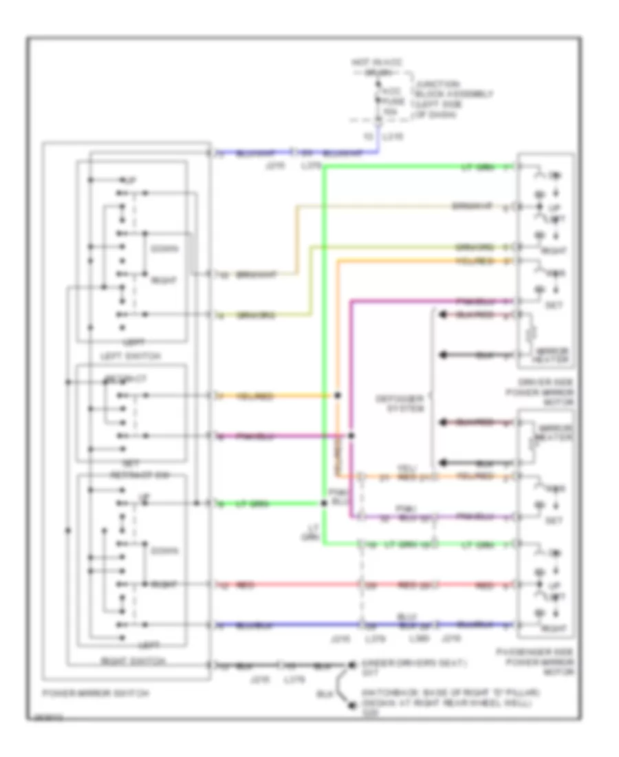
POWER MIRRORS Power Mirrors Wiring Diagram for Suzuki SX4 Crossover 2011 List of elements for Power Mirrors Wiring Diagram for Suzuki SX4 Crossover 2011: 25 (hatchback: base of right "d" pillar) (sedan: at right rear wheel well) g20 (under driver's seat) g17 Acc fuse 15a Defogger system Down Driver side power mirror motor Hot in acc or on J215 J216 Junction block assembly (left side of dash) L315 L379 L380 Left Left switch Mirror heater Passenger side power mirror motor Power mirror switch Red Retract Retract sw Right Right switch Rtr Set
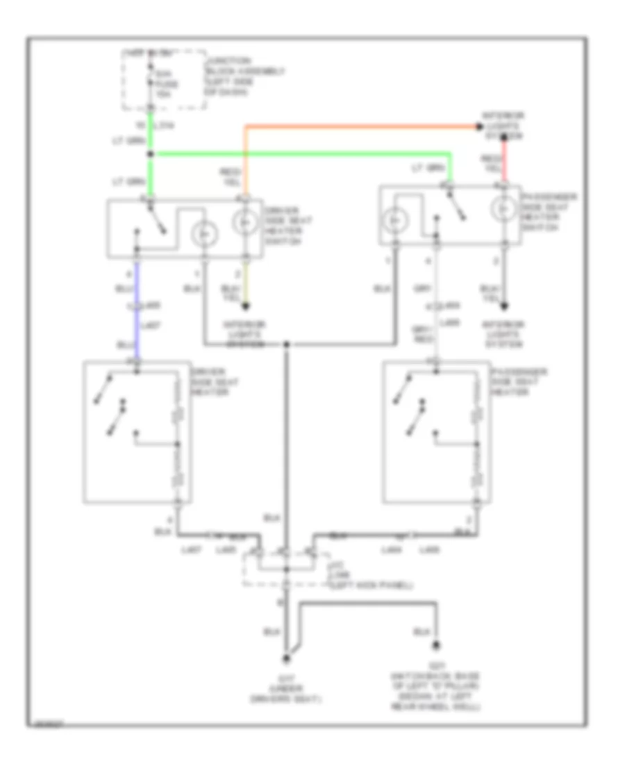
POWER SEATS Power Seats Wiring Diagram for Suzuki SX4 Crossover 2011 List of elements for Power Seats Wiring Diagram for Suzuki SX4 Crossover 2011: 16 Driver side seat heater Driver side seat heater switch G17 (under driver's seat) G21 (hatch back: base of left "d" pillar) (sedan: at left rear wheel well) Hot in on Interior lights system J/c l348 (left kick panel) Junction block assembly (left side of dash) L314 L404 L405 L406 L407 Passenger side seat heater Passenger side seat heater switch S/h fuse 15a
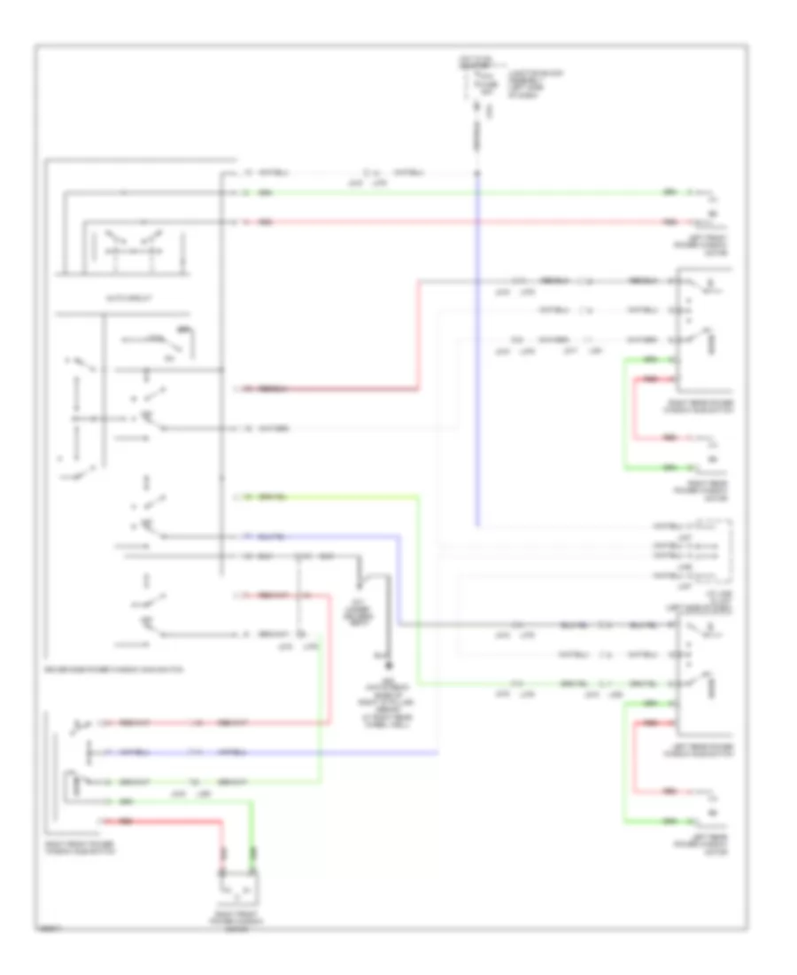
POWER WINDOWS Power Windows Wiring Diagram for Suzuki SX4 Crossover 2011 List of elements for Power Windows Wiring Diagram for Suzuki SX4 Crossover 2011: 35 (hatch back: (under driver's At right rear wheel well) Auto circuit Base of right "d" pillar) (sedan: Down Driver side power window main switch G17 G20 Hot in on or start J/c l346 & l347 (left side of dash) J215 J216 J217 J218 Junction block assembly (left side of dash) L314 L346 L347 L379 L380 L381 L382 Left front power window motor Left rear power window motor Left rear power window sub switch Lock Off P/w fuse 30a Red Right front power window motor Right front power window sub switch Right rear power window motor Right rear power window sub switch Seat)
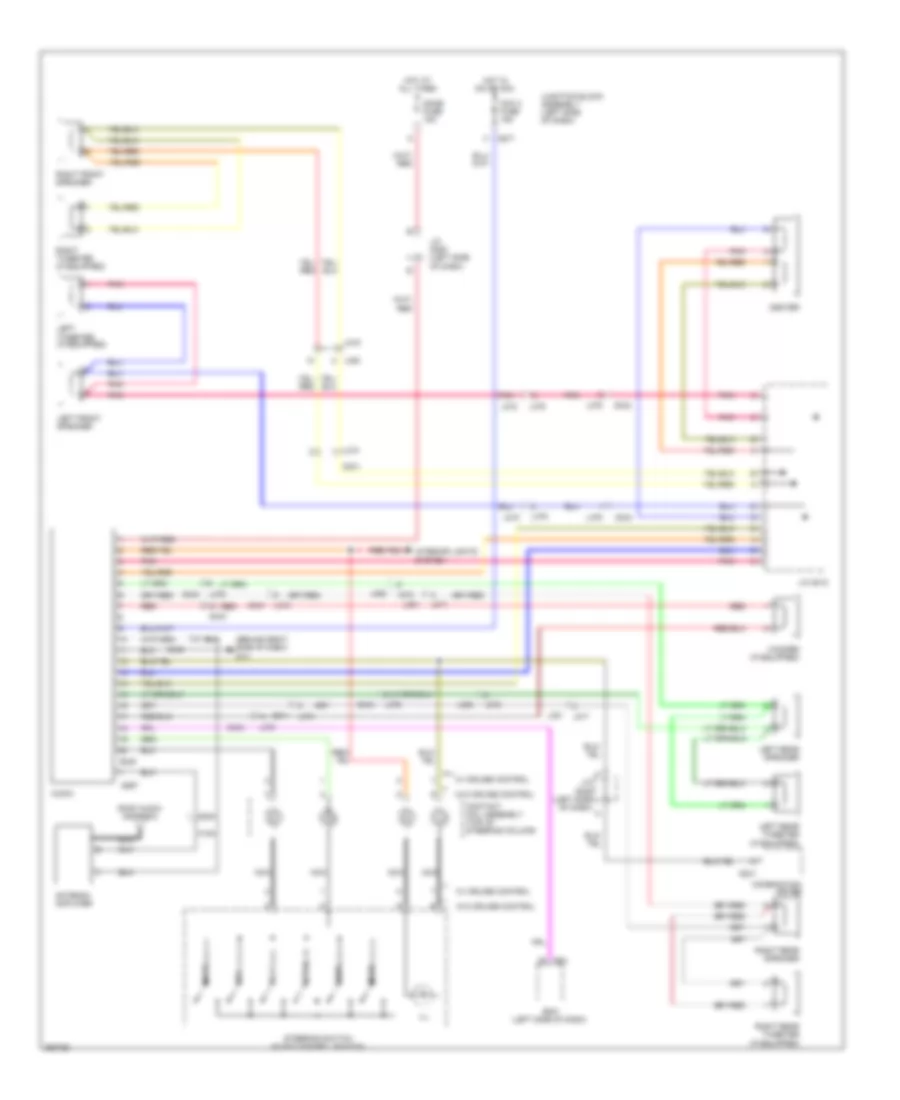
RADIO Radio Wiring Diagram for Suzuki SX4 Crossover 2011 List of elements for Radio Wiring Diagram for Suzuki SX4 Crossover 2011: 61 (behind right side of dash) g14 Acc 2 fuse 15a Antenna amplifier Audio Bcm (left side of dash) Center Combination meter Contact coil assembly (top of steering column) Dome fuse 15a G04 G241 G248 G267 G271 G341 G341 l374 G343 G348 G354 Hot at all times Hot in on or acc Ill Interior lights system J/c g306 (left side of dash) J/c g308 (left side of dash) J/c g312 J215 J216 J217 J218 Junction block assembly (left side of dash) K154 L374 L374 g341 L376 L379 L380 L381 L382 Left front speaker Left rear speaker Left rear tweeter (if equipped) Left tweeter (if equipped) Mode Mute Nca Pnk Red Right front speaker Right rear speaker Right rear tweeter (if equipped) Right tweeter (if equipped) Roof audio antenna Seek+ Seek- Steering switch (audio control switch) Vol+ Vol- W/ cruise control W/o cruise control Woofer (if equipped)
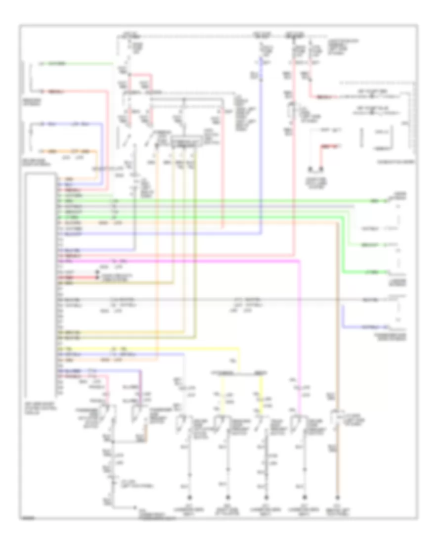
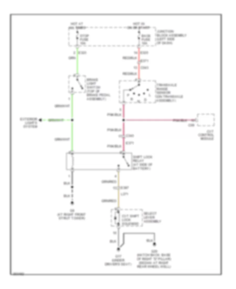
SHIFT INTERLOCK Shift Interlock Wiring Diagram for Suzuki SX4 Crossover 2011 List of elements for Shift Interlock Wiring Diagram for Suzuki SX4 Crossover 2011: 22 Back fuse 10a Brake light switch (top of brake pedal assembly) C09 C343 Cvt control module Cvt shift lock solenoid E323 E325 E371 E387 Exterior lights system G17 (under driver's seat) G20 (hatch back: base of right "d" pillar) (sedan: at right rear wheel well) G9 (at right front strut tower) Hot at all times Hot in on or start Junction block assembly (left side of dash) L371 Select lever assembly Shift lock relay (at side of battery) Stop fuse 10a Transaxle range sensor (on transaxle assembly)
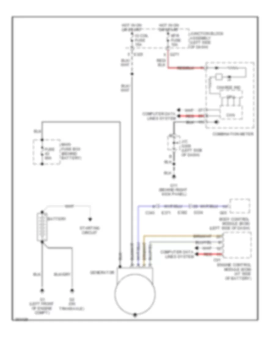
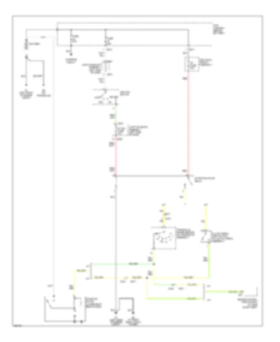
STARTING/CHARGING Charging Wiring Diagram for Suzuki SX4 Crossover 2011 List of elements for Charging Wiring Diagram for Suzuki SX4 Crossover 2011: 29 Battery Body control module (bcm) (left side of dash) C01 C343 Can Charge ind Combination meter Computer data lines system Cpu E325 E371 E382 Engine control module (ecm) (at side of battery) Fuse 80a G05 G1 (left front of engine compt) G11 (behind right kick panel) G2 (on transaxle) G271 G334 Generator Hot in on or start Ig coil fuse 15a J/c g309 (left side of dash) Junction block assembly (left side of dash) Main fuse box (behind battery) Mtr fuse 10a Red Starting circuit Starting Wiring Diagram for Suzuki SX4 Crossover 2011 List of elements for Starting Wiring Diagram for Suzuki SX4 Crossover 2011: 33 A/t Acc Battery C343 Charging circuit Clutch pedal (cpp) switch (at clutch pedal assembly) E01 E311 E312 E324 E325 E371 Engine control module (ecm) (at side of battery) Fuse 50a Fuse 80a G1 (left front of engine compt) G2 (on transaxle) G273 G7 (left rear of engine compt) G9 (at right front strut tower) Ignition switch Individual circuit fuse box 1 Junction block assembly (left side of dash) Lock M/t Main fuse box (behind battery) Red St fuse 30a St sig fuse 10a Start Starting motor (lower right rear of eng) Starting motor relay Transaxle range sensor (on transaxle assembly)
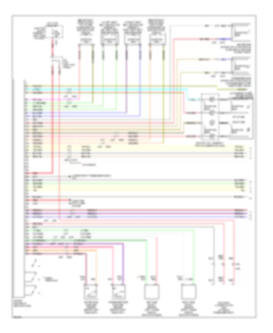
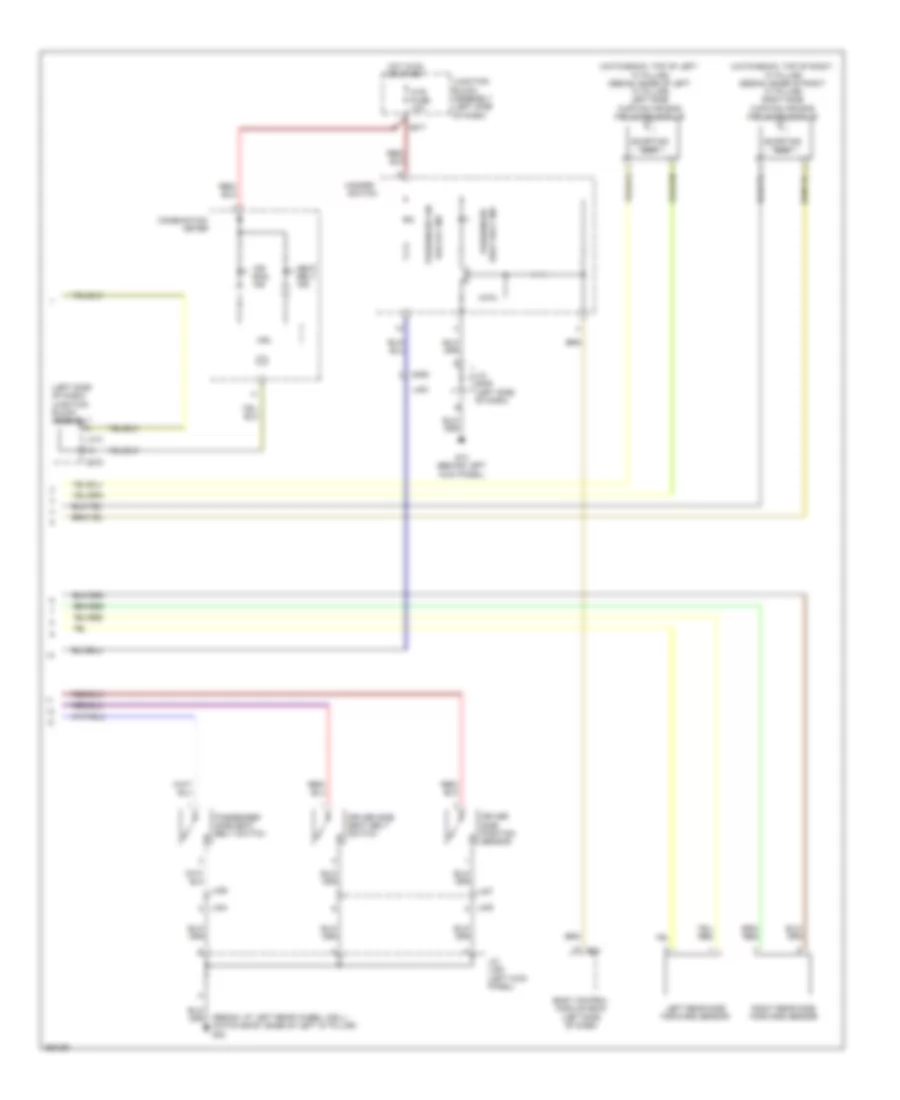
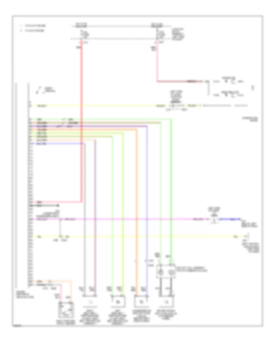
SUPPLEMENTAL RESTRAINTS Supplemental Restraints Wiring Diagram, with Advanced Air Bags (1 of 2) for Suzuki SX4 Crossover 2011 List of elements for Supplemental Restraints Wiring Diagram, with Advanced Air Bags (1 of 2) for Suzuki SX4 Crossover 2011: 49 (behind right side of dash) (1st stage) passenger air bag (inflator) module (behind right side of dash) (2nd stage) passenger air bag (inflator) module (in left seat belt retractor assembly) left seat belt pretensioner (in right seat belt retractor assembly) right seat belt pretensioner (in steering wheel) driver air bag (inflator) module (under front passenger's seat) g15 1st stage 2nd stage A/b fuse 15a A/b sdm (center of vehicle floor) Check terminals Computer data lines system Contact coil assembly (top of steering column) Driver side air bag (inflator) module (in driver outer side of seat back) Driver side forward sensor (behind left headlight) E389 G351 G353 Hatchback Hot in on or start J/c l352 (left kick panel) J215 J216 Junction block assembly (left side of dash) L313 L379 L380 L384 L385 L395 L398 L401 L403 L404 L405 L406 L407 Left side impact sensor (left lower side of vehicle chassis) Nca Occupant classification ecm (at front passenger seat) Passenger side air bag (inflator) module (in passenger outer side of seat back) Passenger side forward sensor (behind right headlight) Pnk Q132 Q133 Q134 Red Right side impact sensor (right lower side of vehicle chassis) Shorting bar Supplemental Restraints Wiring Diagram, with Advanced Air Bags (2 of 2) for Suzuki SX4 Crossover 2011 List of elements for Supplemental Restraints Wiring Diagram, with Advanced Air Bags (2 of 2) for Suzuki SX4 Crossover 2011: 36 (hatchback: top of left "c" pillar) (sedan: base of left "c" pillar) left side curtain air bag (inflator) module (hatchback: top of right "c" pillar) (sedan: base of right "c" pillar) right side curtain air bag (inflator) module (left side of dash) junction block assembly (sedan: at left rear wheel well) (hatch back: base of left "d" pillar) g22 Air bag ind Bag off ind Body control module (bcm) (left side of dash) Combination Cpu Driver side position sensor Driver side seat belt switch G04 G13 (behind left kick panel) G271 G272 G350 Hazard switch Hot in on or start J/c g309 (left side of dash) J/c l353 (left kick panel) Junction block assembly (left side of dash) L313 L400 L404 L405 L406 L407 Left rear side forward sensor Meter Mtr fuse 10a Passenger Passenger air Passenger side seat belt switch Right rear side forward sensor Seat belt ind Shorting bar Supplemental Restraints Wiring Diagram, without Advanced Air Bags for Suzuki SX4 Crossover 2011 List of elements for Supplemental Restraints Wiring Diagram, without Advanced Air Bags for Suzuki SX4 Crossover 2011: 37 (left side of dash) j/c g308 (left side of dash) junction block assembly A/b fuse 15a A/b sdm (center of vehicle floor) Air bag ind Body control module (bcm) (left side of dash) Check terminal Combination meter Contact coil assembly (top of steering column) Cpu Dlc (below left side of dash) Driver air bag (inflator) module (in steering wheel) E388 G04 G15 (under front passenger's seat) G271 G272 G344 G345 G349 Hot in on or start Junction block assembly (left side of dash) L313 L372 L377 L378 L399 Left seat belt pretensioner (in left seat belt retractor assembly) Mtr fuse 10a Nca Passenger air bag (inflator) module (behind right side of dash) Red Right forward impact sensor Right seat belt pretensioner (in right seat belt retractor assembly) Seat belt ind W/ auto cruise W/o auto cruise
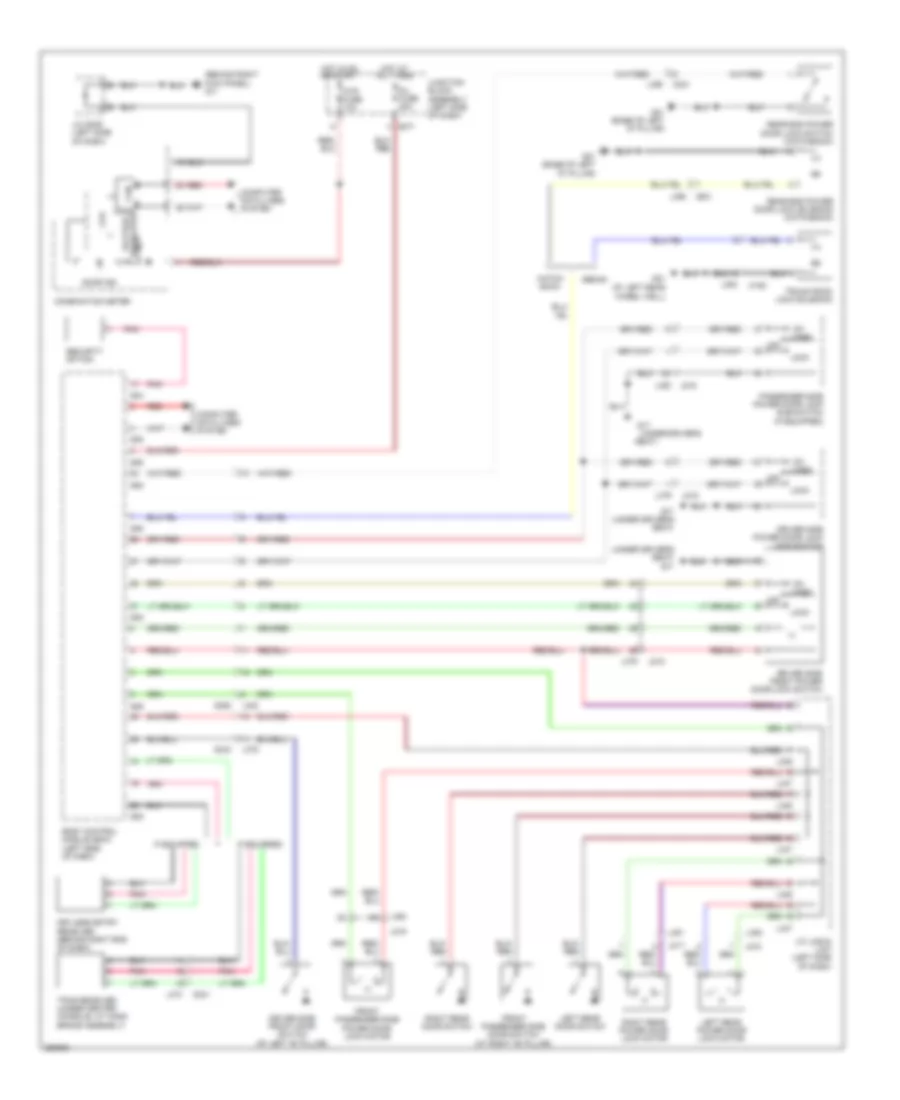
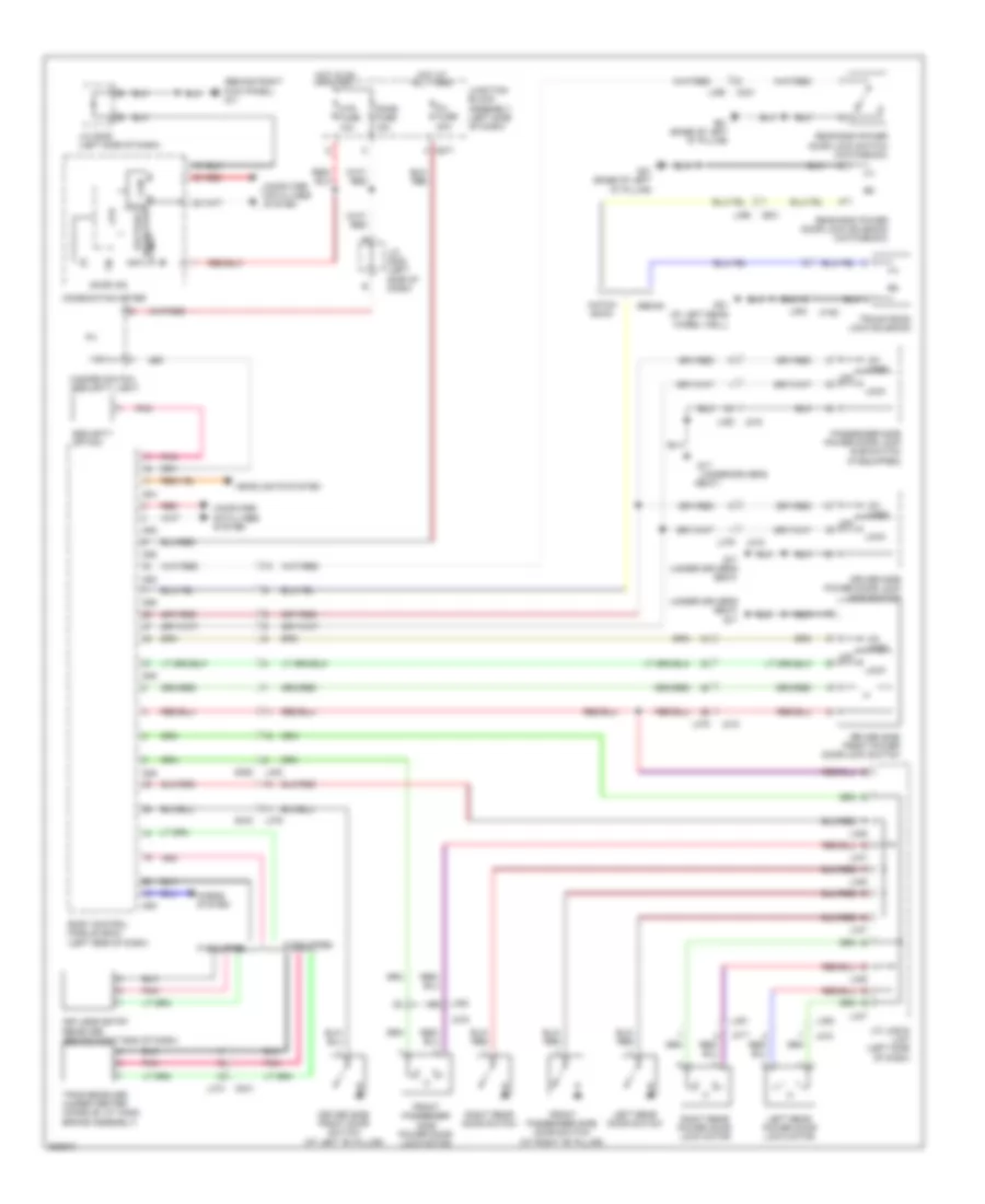
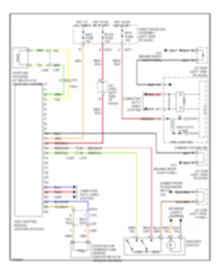
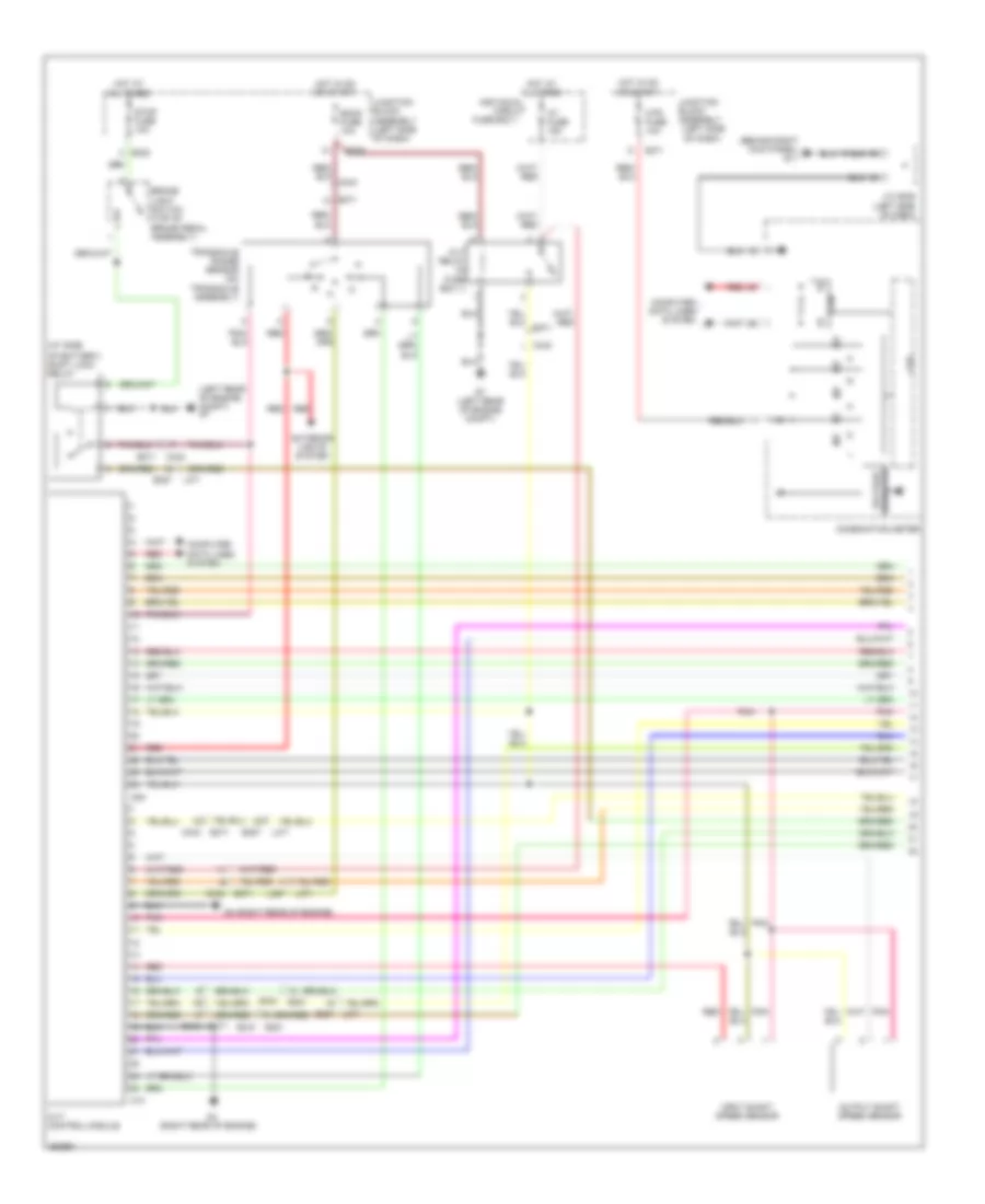
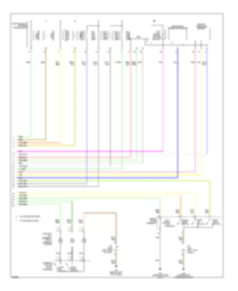
TRANSMISSION 4WD Wiring Diagram for Suzuki SX4 Crossover 2011 List of elements for 4WD Wiring Diagram for Suzuki SX4 Crossover 2011: 32 (under front passenger's seat) 2wd/4wd switch 4wd 4wd auto ind 4wd control module (center of dash) 4wd fuse 15a 4wd lock ind Back fuse 10a C p u Can Combination meter Computer data lines system Coupling air temperature sensor (center rear of vehicle chassis) Coupling solenoid (at rear axle coupling assembly) G11 (behind right kick panel) G16 G271 G272 G343 Hot at all times Hot in on or start Interior lights system J/c g306 (left side of dash) J/c g309 (left side of dash) J/c l348 (left kick panel) Junction block assembly (left side of dash) L376 L397 L408 Lock Mtr fuse 10a Red A/T Wiring Diagram (1 of 2) for Suzuki SX4 Crossover 2011 List of elements for A/T Wiring Diagram (1 of 2) for Suzuki SX4 Crossover 2011: 52 (at side (behind right kick panel) g11 (left rear of engine (left rear of engine compt) g7 (left side (right rear of engine) (right rear of engine) g4 Assembly At fuse 15a Back fuse 10a Block Brake light switch (top of brake pedal assembly) C09 C10 C343 C343 e371 Can Circuit Combination meter Compt) Computer data lines system Cpu Cvt control module Cvt relay (in fuse box 1) E323 E325 E371 E381 E387 E387 l371 Exterior lights system Fuse box 1 G271 G333 Hot at all times Hot in on or start Individual Input shaft speed sensor J/c g309 (left side of dash) Junction Junction block assembly (left side of dash) L371 L387 Mtr fuse 10a Of battery) shift lock relay Of dash) Output shaft speed sensor Pnk Red Stop fuse 10a Transaxle range sensor (on transaxle assembly) Voltage regulator A/T Wiring Diagram (2 of 2) for Suzuki SX4 Crossover 2011 List of elements for A/T Wiring Diagram (2 of 2) for Suzuki SX4 Crossover 2011: 35 Assembly Contact coil assembly (top of steering column) Continuously Cvt Cvt shift lock solenoid Duty solenoid Fluid G13 (behind left kick panel) G16 (under front passenger's seat) G17 (under driver's seat) J/c g309 (left side of dash) J/c l348 (left kick panel) Manual mode switch Nca On/off solenoid Pnk Pressure sensor Primary pressure sensor Primary solenoid Rom Secondary Secondary solenoid Select lever Shift down switch Shift up switch Steering switch (shift paddles) Stepper motor 1 Stepper motor 2 Stepper motor 3 Stepper motor 4 Tempe- rature sensor Transmission Variable W/ cruise control W/o cruise control
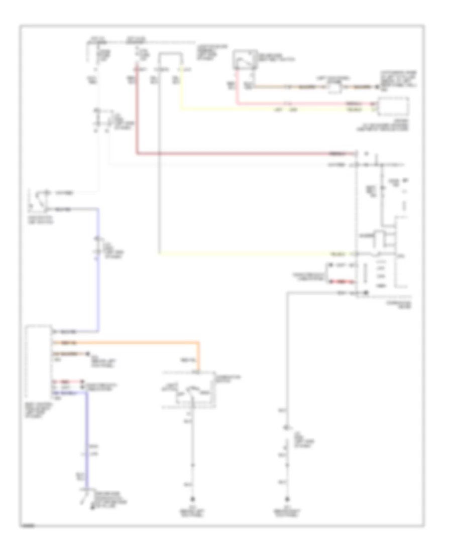
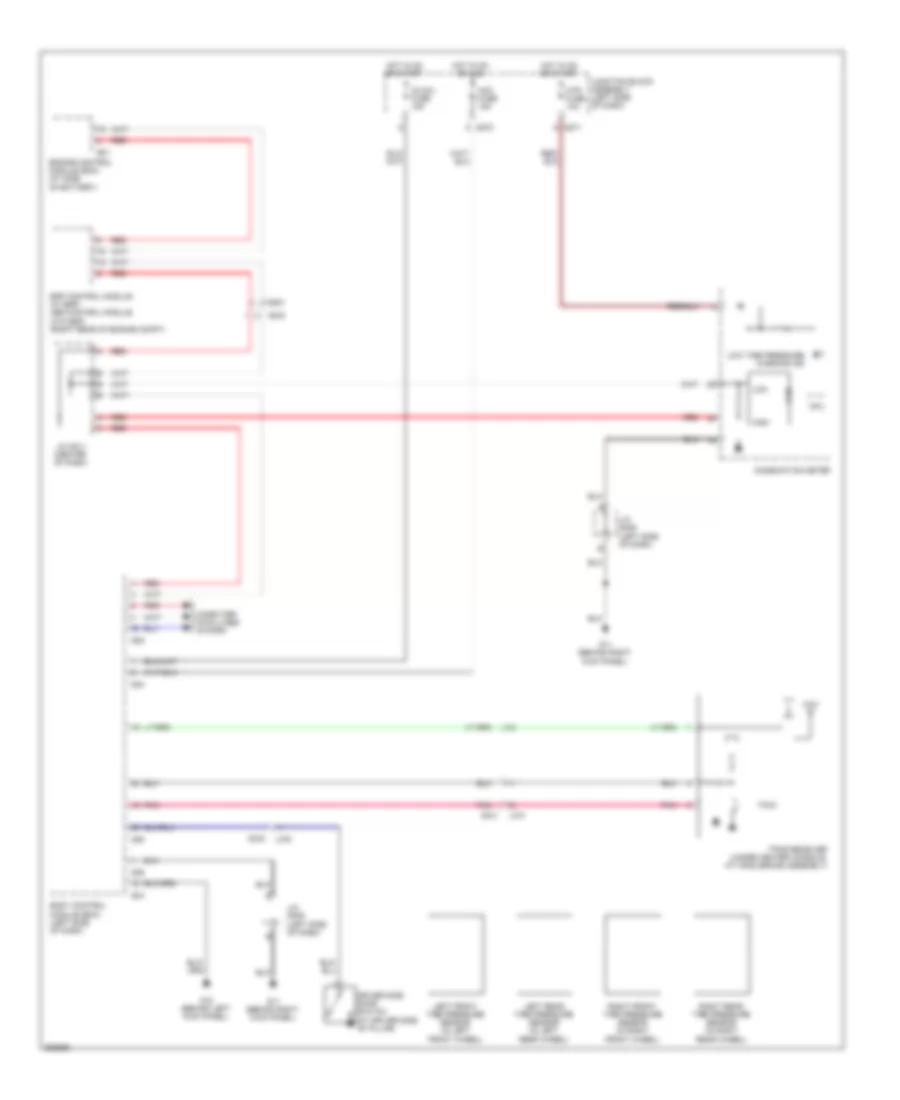
WARNING SYSTEMS Chime Wiring Diagram for Suzuki SX4 Crossover 2011 List of elements for Chime Wiring Diagram for Suzuki SX4 Crossover 2011: 42 (hatchback: base of left "d" pillar) (sedan: at left rear wheel well) g22 (left kick panel) j/c l353 A/b sdm (w/ advanced air bags) (center of vehicle floor) Body control module (bcm) (left side of dash) Buzzer Can Combination meter Combination switch Computer data lines system Cpu Dome fuse 15a Door ind Driver side door switch (at driver side "b" pillar) Driver side seat belt switch G04 G05 G11 (behind right kick panel) G12 (behind left kick panel) G13 (behind left kick panel) G271 G272 G343 Head High Hot at all times Hot in on or start J/c g307 (left end of dash) J/c g308 (left side of dash) J/c g309 (left side of dash) Junction block assembly (left side of dash) L313 L376 L405 L407 Light switch Low Main switch (key switch) Mtr fuse 10a Off Red Seat belt ind Tail Tire Pressure Monitoring Wiring Diagram for Suzuki SX4 Crossover 2011 List of elements for Tire Pressure Monitoring Wiring Diagram for Suzuki SX4 Crossover 2011: 40 Acc fuse 15a Body control module (bcm) (left side of dash) Can Combination meter Computer data lines system Cpu Driver side door switch (at driver side "b" pillar) E01 E381 Engine control module (ecm) (at side of battery) Esp control module (w/ esp) abs control module (w/o esp) (right rear of engine compt) G04 G05 G06 G11 (behind right kick panel) G12 (behind left kick panel) G271 G272 G333 G341 G343 High Hot in on or acc Hot in on or start Ig coil fuse 15a J/c g309 (left side of dash) J/c g311 (center of dash) Junction block assembly (left side of dash) L374 L376 Left front tire pressure sensor (in left front wheel) Left rear tire pressure sensor (in left rear wheel) Low Low tire pressure warning ind Mtr fuse 10a Pnk Red Right front tire pressure sensor (in right front wheel) Right rear tire pressure sensor (in right rear wheel) Tpms receiver (under center console, at hand brake assembly)
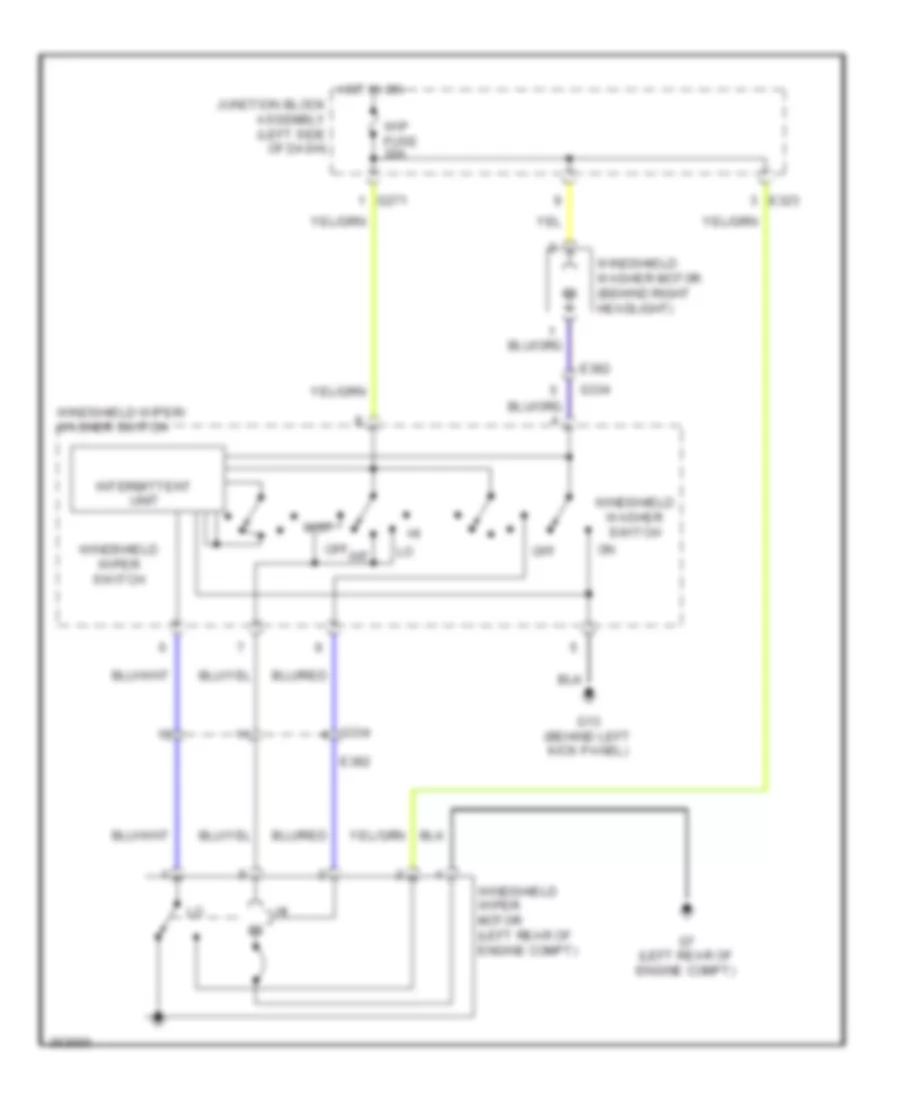
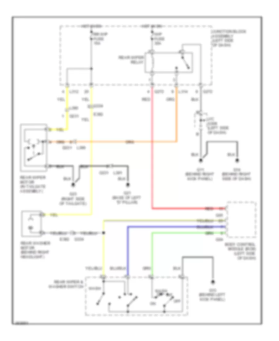
WIPER/WASHER Front Wiper/Washer Wiring Diagram for Suzuki SX4 Crossover 2011 List of elements for Front Wiper/Washer Wiring Diagram for Suzuki SX4 Crossover 2011: 18 E323 E382 G13 (behind left kick panel) G271 G334 G7 (left rear of engine compt) Hot in on Int Intermittent unit Junction block assembly (left side of dash) Mist Off Windshield washer motor (behind right headlight) Windshield washer switch Windshield wiper motor (left rear of engine compt) Windshield wiper switch Windshield wiper/ washer switch Wip fuse 30a Rear Wiper/Washer Wiring Diagram for Suzuki SX4 Crossover 2011 List of elements for Rear Wiper/Washer Wiring Diagram for Suzuki SX4 Crossover 2011: 32 (right side of tailgate) Body control module (bcm) (left side of dash) D231 E382 G04 G05 G11 (behind right kick panel) G13 (behind left kick panel) G14 (behind right side of dash) G21 (base of left "d" pillar) G23 G272 G334 Hot in on Int J/c g309 (left side of dash) Junction block assembly (left side of dash) L312 L314 L390 L391 O231 Off Rear washer motor (behind right headlight) Rear wiper & washer switch Rear wiper motor (in tailgate assembly) Rear wiper relay Red Rr wip fuse 15a Wash Wash on+ Wip fuse 30a