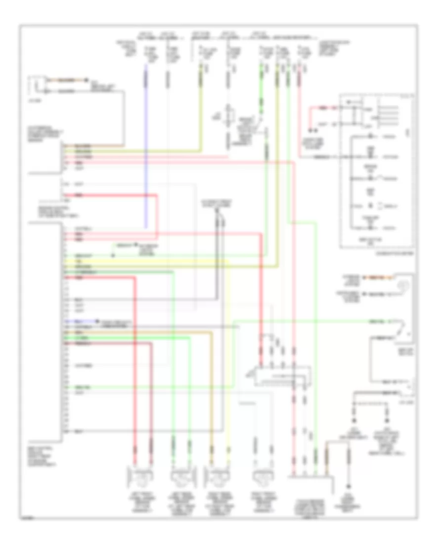
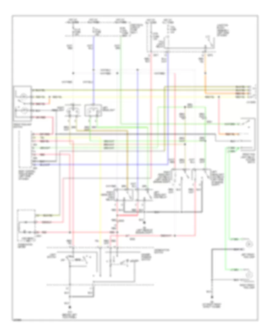
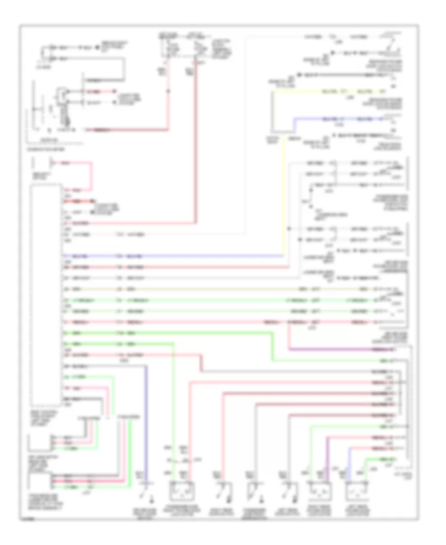
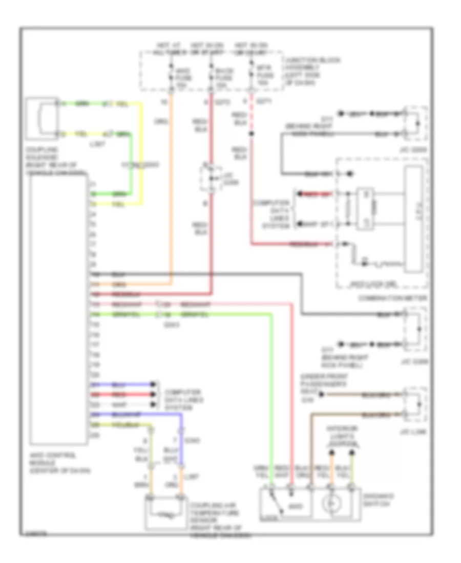
AIR CONDITIONING
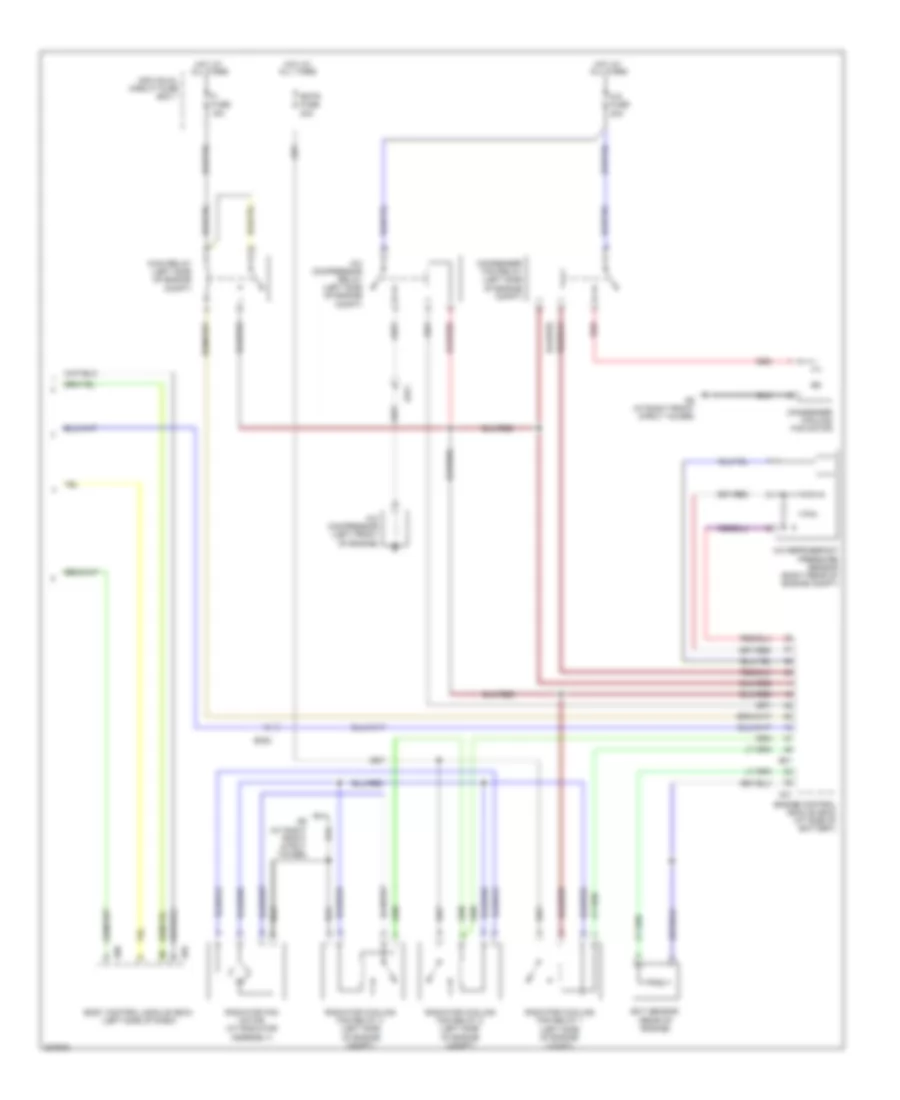
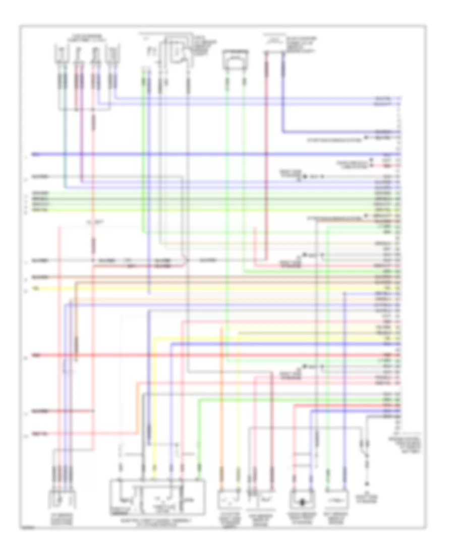
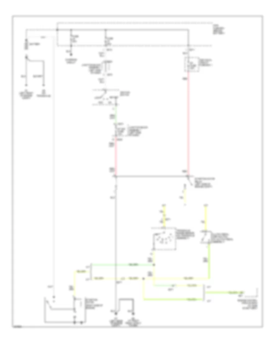
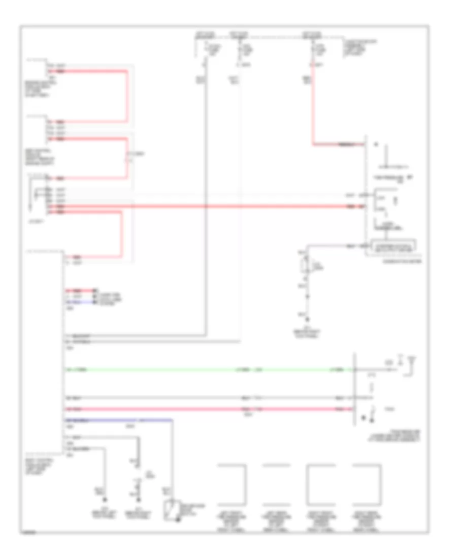
Automatic A/C Wiring Diagram (1 of 2) for Suzuki SX4 Sport S 2010

List of elements for Automatic A/C Wiring Diagram (1 of 2) for Suzuki SX4 Sport S 2010:
- Acc fuse 15a
- Air flow control actuator (left side of dash)
- Air intake actuator (right side of dash)
- Back fuse 10a
- Blower motor (behind right side of dash)
- Blower motor relay
- Blower motor resister (behind right side of dash, near blower motor)
- Blw fuse 30a
- Computer data lines system
- Defogger system
- Diode 1 (left side of dash)
- E323
- Evaporator temperature sensor (center of dash)
- G11 (behind right kick panel)
- G13 (behind left kick panel)
- G14 (behind right side of dash)
- G272
- G273
- Hot at all times
- Hot in on
- Hot in on or acc
- Hot in on or start
- Hvac control module (center of dash)
- Ig2 sig fuse 10a
- Individual circuit fuse box 1
- Inside air temperature sensor (left side of dash)
- Interior lights system
- J/c g306
- J/c g309
- J/c g310
- Junction block assembly (left side of dash)
- Pnk
- Red
- Sunload sensor (left side of dash)
- Temperature control actuator (left side of dash)
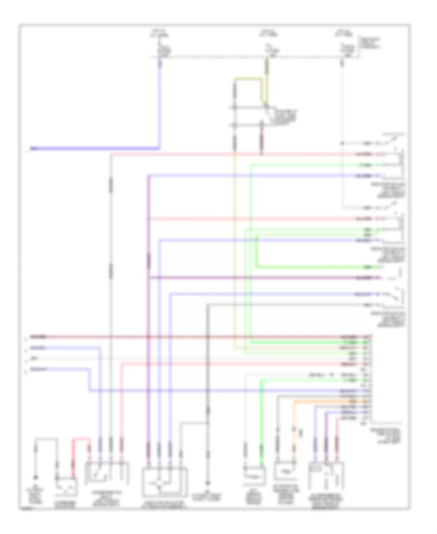
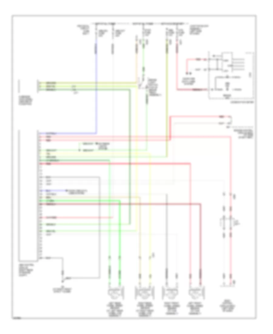
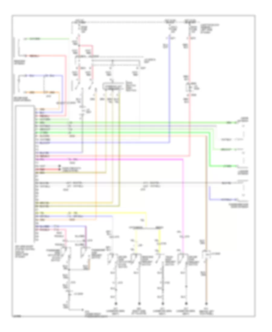
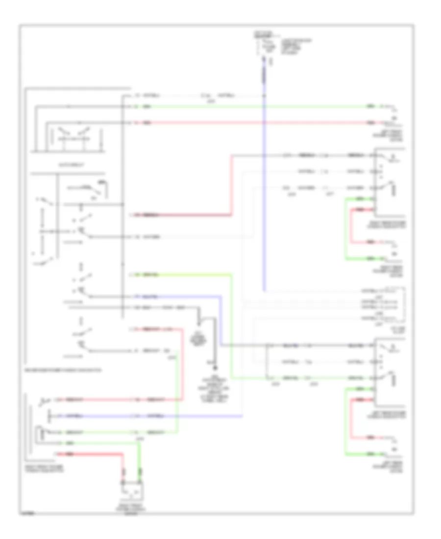
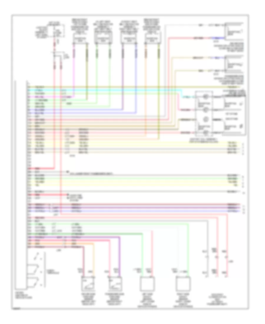
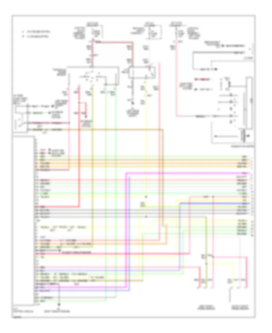
Automatic A/C Wiring Diagram (2 of 2) for Suzuki SX4 Sport S 2010
List of elements for Automatic A/C Wiring Diagram (2 of 2) for Suzuki SX4 Sport S 2010:
- (left side of engine compt)
- A/c compressor (left front of engine)
- A/c compressor relay (left side of engine compt)
- A/c fuse 20a
- A/c refrigerant pressure sensor (right rear of engine compt)
- Body control module (bcm) (left side of dash)
- C01
- Condenser cooling fan motor
- Condenser fan relay (left side of engine compt)
- E01
- E371
- E382
- Ect sensor (rear of engine)
- Engine control module (ecm) (at side of battery)
- Fi fuse 15a
- G04
- G05
- G9 (at right front strut tower)
- Hot at all times
- Individual circuit fuse box 1
- Main relay (left side of engine compt)
- Radiator cooling fan relay 1
- Radiator cooling fan relay 2 (left side of engine compt)
- Radiator cooling fan relay 3 (left side of engine compt)
- Radiator fan motor (at radiator assembly)
- Rdtr fuse 30a
- Red
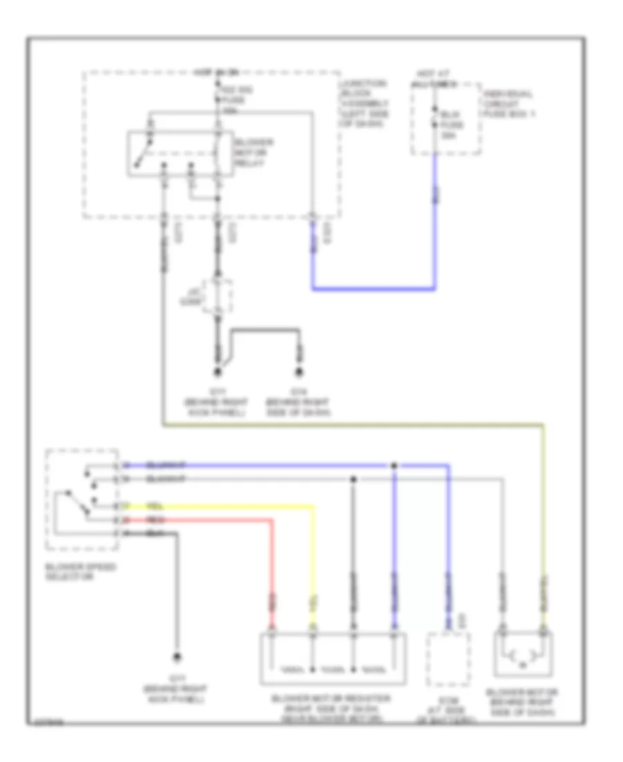
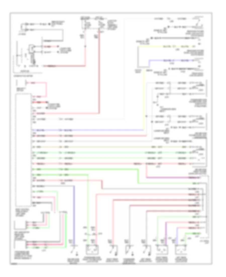
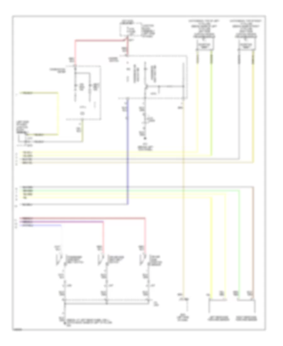
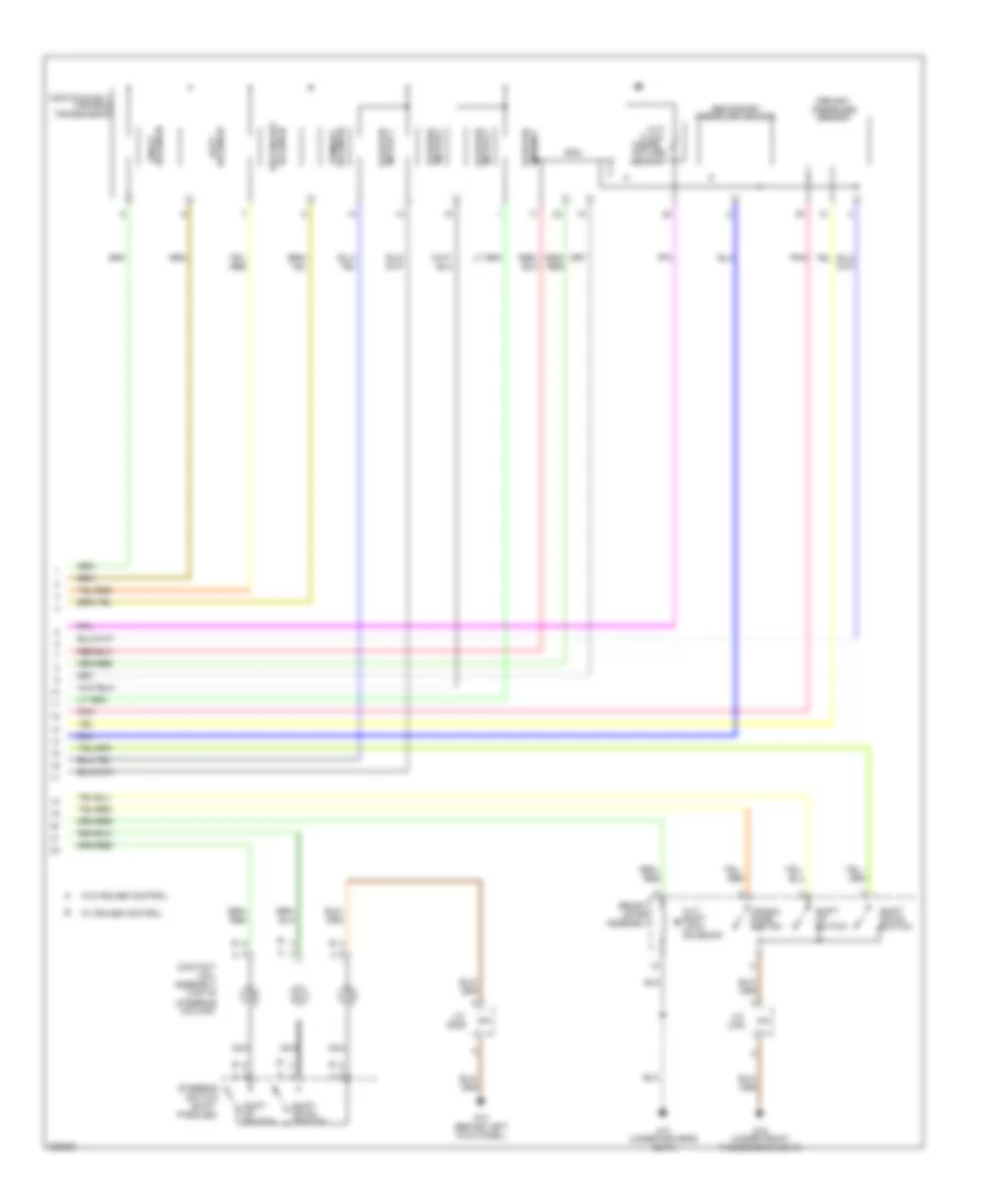
Heater Wiring Diagram for Suzuki SX4 Sport S 2010
List of elements for Heater Wiring Diagram for Suzuki SX4 Sport S 2010:
- (at side of battery)
- Blower motor (behind right side of dash)
- Blower motor relay
- Blower motor resister (right side of dash, near blower motor)
- Blower speed selector
- Blw fuse 30a
- E01
- E323
- Ecm
- G11 (behind right kick panel)
- G14 (behind right side of dash)
- G272
- G273
- Hot at all times
- Hot in on
- Ig2 sig fuse 10a
- Individual circuit fuse box 1
- J/c g309
- Junction block assembly (left side of dash)
- Red
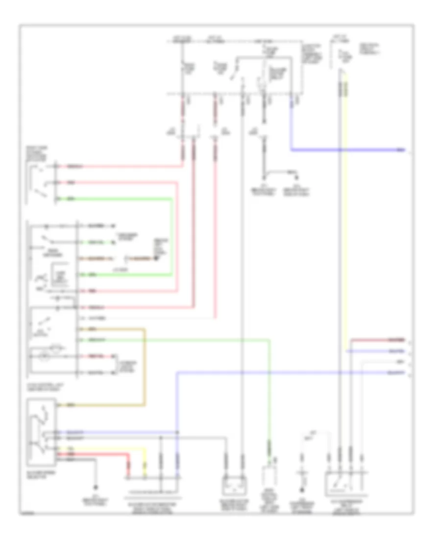
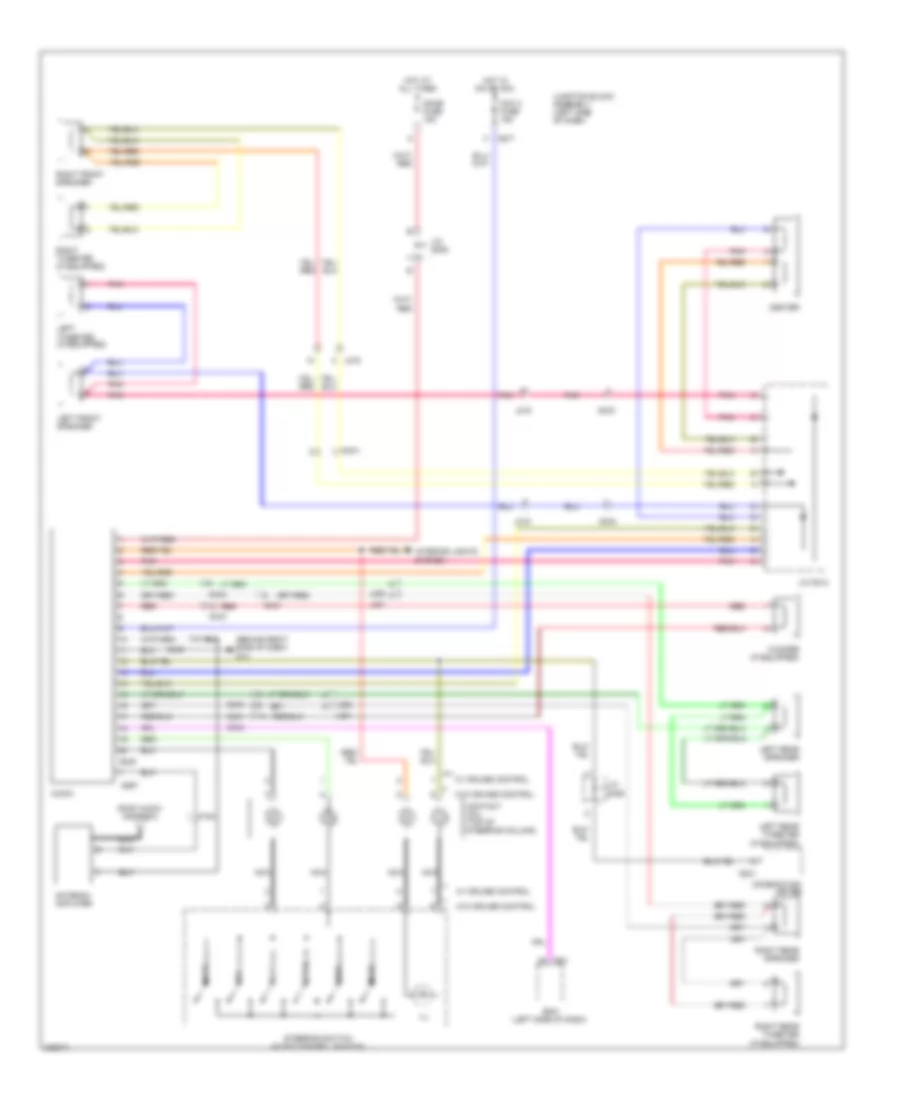
Manual A/C Wiring Diagram (1 of 2) for Suzuki SX4 Sport S 2010
List of elements for Manual A/C Wiring Diagram (1 of 2) for Suzuki SX4 Sport S 2010:
- (behind left kick panel) g13
- (right side of dash) air intake actuator
- A/c compressor (left front of engine)
- A/c compressor relay (left side of engine compt)
- A/c fuse 20a
- A/c switch
- Back fuse 10a
- Blower motor (behind right side of dash)
- Blower motor relay
- Blower motor resister (right side of dash, near blower motor)
- Blower speed selector
- Body control module (bcm) (left side of dash)
- Defogger system
- Dome fuse 15a
- E323
- E371
- Fre
- G05
- G11 (behind right kick panel)
- G14 (behind right side of dash)
- G271
- G272
- G273
- Harf rec circuit
- Hot at all times
- Hot in on
- Hot in on or start
- Hvac control unit (center of dash)
- Ig2 sig fuse 10a
- Individual circuit fuse box 1
- Interior lights system
- J/c g306
- J/c g308
- J/c g309
- Junction block assembly (left side of dash)
- Rear defogger
- Rec
- Red
Manual A/C Wiring Diagram (2 of 2) for Suzuki SX4 Sport S 2010
List of elements for Manual A/C Wiring Diagram (2 of 2) for Suzuki SX4 Sport S 2010:
- A/c refrigerant pressure sensor (right rear of engine compt)
- Blw fuse 30a
- C01
- Condenser fan motor
- Condenser fan relay (left side of engine compt)
- E01
- E382
- Ect sensor (rear of engine)
- Engine control module (ecm) (at side of battery)
- Evaporator temperature sensor (center of dash)
- Fi fuse 15a
- G9 (at right front strut tower)
- Hot at all times
- Individual circuit fuse box 1
- Main relay (left side of engine compt)
- Radiator cooling fan relay 1 (left side of engine compt)
- Radiator cooling fan relay 2 (left side of engine compt)
- Radiator cooling fan relay 3 (left side of engine compt)
- Radiator fan motor (at radiator assembly)
- Rdtr fuse 30a
- Red
ANTI-LOCK BRAKES
Anti-lock Brakes Wiring Diagram, with ESP for Suzuki SX4 Sport S 2010
List of elements for Anti-lock Brakes Wiring Diagram, with ESP for Suzuki SX4 Sport S 2010:
- (at right front strut tower) g8
- (in steering column assembly) steering angle sensor
- Abs fuse 10a
- Abs ind
- Abs mot fuse 40a
- Abs sol fuse 30a
- Brake ind
- Brake light switch (top of brake pedal assembly)
- Can
- Combination meter
- Computer data lines system
- Cpu
- Dome fuse 15a
- E01
- E323
- E325
- E381
- Engine control module (ecm) (at side of battery)
- Esp active ind
- Esp control module (right rear of engine compartment)
- Esp ind
- Esp off switch
- Exterior lights system
- G13 (behind left kick panel)
- G16 (under front passenger's seat)
- G17 (under driver's seat)
- G21 (hatch back: base of left "d" pillar) (sedan: at left rear wheel well)
- G271
- G272
- G341
- High
- Hot at all times
- Hot in on or start
- Ig 1 sig fuse 10a
- Individual circuit fuse box 1
- Instrument cluster system
- Interior lights system
- J/c 309
- J/c g308
- J/c g311
- J/c l348
- Junction block assembly (left side of dash)
- L315
- Left front wheel speed sensor (at hub assembly)
- Left rear wheel speed sensor (at left rear wheel hub assembly)
- Low
- Mtr fuse 10a
- Red
- Right front wheel speed sensor (at hub assembly)
- Right rear wheel speed sensor (at right rear wheel hub assembly)
- Stop fuse 15a
- Tcss off ind
- Yaw/g sensor (under center console, below parking brake handle)
Anti-lock Brakes Wiring Diagram, without ESP for Suzuki SX4 Sport S 2010
List of elements for Anti-lock Brakes Wiring Diagram, without ESP for Suzuki SX4 Sport S 2010:
- Abs control module (right rear of engine compt)
- Abs fuse 10a
- Abs ind
- Abs mot fuse 40a
- Abs sol fuse 30a
- Body control module (bcm) (left side of dash)
- Brake ind
- Brake light switch (top of brake pedal assembly)
- Can
- Combination meter
- Computer data lines system
- Computer data lines system
- Cpu
- E01
- E323
- E325
- E381
- Engine control module (ecm) (at side of battery)
- Exterior lights system
- G sensor (4wd model) (center of floor pan)
- G05
- G271
- G8 (at right front strut tower)
- High
- Hot at all times
- Hot in on or start
- Individual circuit fuse box 1
- J/c g311
- Junction block assembly (left side of dash)
- L315
- L371
- Left front wheel speed sensor (at hub assembly)
- Left rear wheel speed sensor (at left rear wheel hub assembly)
- Low
- Mtr fuse 10a
- Red
- Right front wheel speed sensor (at hub assembly)
- Right rear wheel speed sensor (at right rear wheel hub assembly)
- Stop fuse 10a
ANTI-THEFT
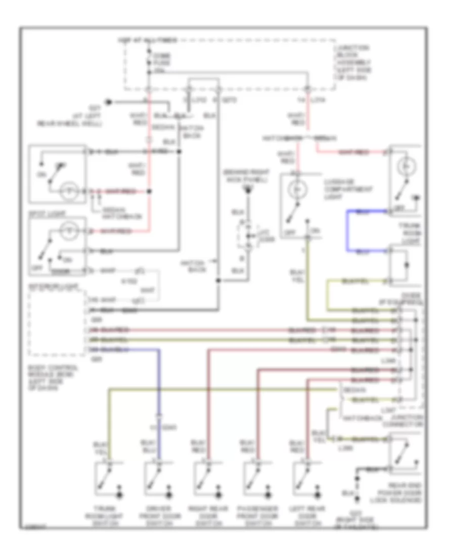
Forced Entry Wiring Diagram for Suzuki SX4 Sport S 2010
List of elements for Forced Entry Wiring Diagram for Suzuki SX4 Sport S 2010:
- (base of left "d" pillar)
- (behind right kick panel) g11
- (under driver's
- (under driver's seat)
- Body control module (bcm) (left side of dash)
- Can
- Combination meter
- Computer data lines system
- Cpu
- D/l fuse 20a
- Door ind
- Driver side front door switch
- Driver side front power door lock switch
- Driver side power door lock main switch
- G04
- G05
- G06
- G17
- G17 (under driver's seat)
- G21
- G21 (base of left "d" pillar)
- G271
- G352
- Hatch- back
- Hot at all times
- Hot in on or start
- J/c g309
- J/c l346 & l347
- J215
- J216
- Junction block assembly (left side of dash)
- Keyless entry receiver (left side of dash)
- L346
- L347
- L374
- L381
- L382
- L390
- Left rear door switch
- Left rear power door lock motor
- Lock
- M152
- Mtr fuse 10a
- Off
- Passenger side front door switch
- Passenger side front power door lock motor
- Passenger side power door lock sub switch (if equipped)
- Pnk
- Rear end power door lock solenoid (hatch back)
- Rear end power door lock switch (hatch back)
- Red
- Regulator voltage
- Right rear door switch
- Right rear power door lock motor
- Seat)
- Security option
- Sedan
- Tpms receiver (under center console, at hand brake assembly)
- Trunk room lock solenoid
- Un- lock
- W/ tpms
- W/o tpms
Immobilizer Wiring Diagram for Suzuki SX4 Sport S 2010
List of elements for Immobilizer Wiring Diagram for Suzuki SX4 Sport S 2010:
- (at side of battery) engine control module (ecm)
- Body control module (bcm) (left side of dash)
- Can low can high
- Computer data lines system
- Cpu
- Dome fuse 15a
- E01
- E325
- E382
- G06
- G11 (behind right kick panel)
- G241
- G271
- G272
- G3 (right side of engine)
- Hot at all times
- Hot in on or start
- Icm (in steering column assembly)
- Id control module (if equipped)
- Ig coil fuse 15a
- Immobi ind
- Instrument cluster
- J/c g308
- J/c g309
- Junction block assembly (left side of dash)
- Red
- W/ id control module
- W/o id control module
BODY CONTROL MODULES
Body Control Modules Wiring Diagram for Suzuki SX4 Sport S 2010
List of elements for Body Control Modules Wiring Diagram for Suzuki SX4 Sport S 2010:
- Acc fuse 15a
- Air conditioning system
- Body control module (bcm) (left side of dash)
- Computer data lines system
- D/l fuse 20a
- Defogger system
- Dome fuse 15a
- Door locks system
- Door locks system interior lights system
- Exterior lights system
- G04
- G05
- G06
- G11 (behind right kick panel)
- G12 (behind left kick panel)
- G271
- G272
- Headlights system
- Horns system
- Hot at all times
- Hot in on or acc
- Hot in on or start
- Ig coil fuse 15a
- Instrument cluster system
- Interior lights & anti-theft systems
- Interior lights system
- J/c g307
- J/c g308
- J/c g309
- Junction block assembly (left side of dash)
- Main switch (key switch)
- Outside air temperature sensor (behind left side of front bumper)
- Pnk
- Red
- Security option connector
- Sound systems
- Starting/charging system
- Wiper/washer system
COMPUTER DATA LINES
Computer Data Lines Wiring Diagram for Suzuki SX4 Sport S 2010
List of elements for Computer Data Lines Wiring Diagram for Suzuki SX4 Sport S 2010:
- (10ch)
- (center of vehicle floor)
- (if equipped)
- (in steering column assembly)
- (right side of engine)
- 4wd control module (center of dash)
- A/b sdm
- A/b sdm (center of vehicle floor)
- Abs control module (right rear of engine compt)
- Body control module (bcm) (left side of dash)
- C01
- C09
- Combination meter
- Cvt control module
- Dlc (data link connector) (below left side of dash)
- Dome fuse 15a
- E01
- E371
- E381
- E382
- Engine control module (ecm) (at side of battery)
- Esp control module (right rear of engine compt)
- G05
- G11 (behind right kick panel)
- G14 (behind right side of dash)
- G271
- G341
- Hot at all times
- Hvac control module (center of dash)
- Id controller
- J/c g308
- J/c g309
- J/c g311
- Junction block assembly (left side of dash)
- Kls ecm (behind right end of dash)
- Red
- Steering angle sensor (w/ esp)
- Yaw rate/g sensor (w/ esp) (under center console, below parking brake handle)
COOLING FAN
Cooling Fan Wiring Diagram for Suzuki SX4 Sport S 2010
List of elements for Cooling Fan Wiring Diagram for Suzuki SX4 Sport S 2010:
- C01
- E01
- Ect sensor (rear of engine)
- Engine control module (ecm) (at side of battery)
- Engine controls system
- Fi fuse 15a
- G9 (at right front strut tower)
- Hot at all times
- Individual circuit fuse box 1
- Main relay (left side of engine compt)
- Radiator cooling fan relay 1 (left side of engine compartment)
- Radiator cooling fan relay 2 (left side of engine compartment)
- Radiator cooling fan relay 3 (left side of engine compartment)
- Radiator fan motor (at radiator assembly)
- Rdtr fuse 30a
CRUISE CONTROL
Cruise Control Wiring Diagram for Suzuki SX4 Sport S 2010
List of elements for Cruise Control Wiring Diagram for Suzuki SX4 Sport S 2010:
- (left side of dash)
- Acceleration pedal (app) sensor (at accelerator pedal assembly)
- Bcm
- Brake light switch (top of brake pedal assembly)
- C01
- Cancel
- Close
- Computer data lines system
- Contact coil (top of steering column)
- Cpp cut switch (at clutch pedal assembly)
- E01
- E323
- E325
- E383
- Electric throttle body assembly (at intake manifold)
- Engine control module (ecm) (at side of battery)
- Engine controls system
- Exterior lights system
- Fi fuse 15a
- G271
- G272
- G3 (right side of engine)
- G7 (left rear of engine compt)
- Hot at all times
- Hot in on or start
- Id controller
- Ig coil fuse 15a
- Ig1 sig fuse 10a
- Individual circuit fuse box 1
- J/b (left side of dash)
- J/c
- Junction block assembly (left side of dash)
- Main
- Main relay (left side of engine compt)
- Mtr fuse 10a
- Nca
- Open
- Red
- Resume/ accel
- Set/ coast
- Steering switch (automatic cruise switch)
- Stop fuse 10a
- Sub
- Thr mot fuse 15a
- Throttle actuator
- Throttle actuator control relay (left side of engine compt)
- Throttle position sensor
- W/ id controller
- W/o id controller
DEFOGGERS
Defoggers Wiring Diagram, Hatchback for Suzuki SX4 Sport S 2010
List of elements for Defoggers Wiring Diagram, Hatchback for Suzuki SX4 Sport S 2010:
- (automatic a/c)
- (manual a/c)
- Automatic a/c
- Body control module (bcm) (left side of dash)
- Driver side power mirror motor
- G04
- G05
- G13 (behind left kick panel)
- G154
- G17 (under driver's seat)
- G20
- G21 (base of left "d" pillar)
- G23 (right side of tailgate)
- G271
- G272
- G309
- Hot at all times
- Hvac control module (automatic a/c) hvac control unit (manual a/c) (center of dash)
- J/c
- J/c l348
- J215
- J216
- Junction block assembly (left side of dash)
- L314
- L390
- Manual a/c
- Nca
- O181
- O182
- Passenger side power mirror motor
- Rear def
- Rear defogger
- Rear defogger relay
- Rr def fuse 30a
Defoggers Wiring Diagram, Sedan for Suzuki SX4 Sport S 2010
List of elements for Defoggers Wiring Diagram, Sedan for Suzuki SX4 Sport S 2010:
- (automatic a/c)
- (behind left kick panel)
- (manual a/c)
- Automatic a/c
- Body control module (bcm) (left side of dash)
- Condenser
- Driver side power mirror motor
- G04
- G13
- G154
- G17 (under driver's seat) g21 (at left rear wheel well)
- G19 (at right rear wheel well)
- G20
- G20 (at right rear wheel well) g17 (under driver's seat)
- G25 (at right "c" pillar)
- G271
- G309
- G343
- Hot at all times
- Hvac control module (automatic a/c) hvac control unit (manual a/c) (center of dash)
- Individual circuit fuse box 3
- J/b
- J/b side connector (bcm)
- J/c
- J/c g271 & l314
- J/c l348
- J215
- L299
- L300
- L303
- L314
- L315
- L317
- Manual a/c
- Nca
- Passenger side power mirror motor
- Rear def
- Rear defogger
- Rear defogger relay
- Rr def fuse 30a
ENGINE PERFORMANCE
2.0L
2.0L, Engine Performance Wiring Diagram (1 of 3) for Suzuki SX4 Sport S 2010
List of elements for 2.0L, Engine Performance Wiring Diagram (1 of 3) for Suzuki SX4 Sport S 2010:
- (behind right kick panel) g11
- (left side of engine compt) fuel pump relay
- (under driver's seat) g17
- Air conditioning system
- Air conditioning system/ cooling fans system
- Anti-theft system
- App sensor (at accelerator pedal assembly)
- Brake light switch (top of brake pedal assembly)
- Built-in pressure sensor
- Check engine ind
- Close
- Combination meter
- Computer data lines system
- Cpu
- Cruise control system
- Detection pump
- E01
- E323
- E325
- E371
- Electronic power steering system
- Engine control module (ecm) (at side of battery)
- Evap leak check module assembly (if equipped) (left rear of vehicle chassis)
- Fuel pump & fuel gauge
- G24 (top of fuel tank)
- G241
- G271
- G3 (right side of engine)
- G343
- Hot at all times
- Hot in on or start
- Ig1 sig fuse 10a
- J/c g309
- J/c l348
- Junction block assembly (left side of dash)
- L371
- L396
- Main
- Mtr fuse 10a
- Open
- P/s pump pressure switch (front of engine)
- Pnk
- R151
- Red
- Starting/ charging system
- Stop fuse 10a
- Sub
- Vent valve
- W/ p/s control module b
- W/o p/s control module a
2.0L, Engine Performance Wiring Diagram (2 of 3) for Suzuki SX4 Sport S 2010
List of elements for 2.0L, Engine Performance Wiring Diagram (2 of 3) for Suzuki SX4 Sport S 2010:
- (in exhaust pipe) heated oxygen sensor
- (left side of engine compt) throttle actuator control relay
- Anti-theft system
- Clutch pedal (cpp) cut switch (if equipped) (at clutch pedal assembly)
- Cmp sensor (rear of engine)
- D w/ id control module
- Dome fuse 15a
- E323
- E325
- E371
- Fi fuse 15a
- G3 (right side of engine)
- G7 (left rear of engine compt)
- Hot at all times
- Hot in on or start
- Ig coil fuse 15a
- Ignition coil assemblies (top of engine)
- Individual circuit fuse box 1
- Junction block assembly (left side of dash)
- Main relay (left side of engine compt)
- Nca
- Red
- Thr mor fuse 15a
- To spark plug
- W/o id control module c
2.0L, Engine Performance Wiring Diagram (3 of 3) for Suzuki SX4 Sport S 2010
List of elements for 2.0L, Engine Performance Wiring Diagram (3 of 3) for Suzuki SX4 Sport S 2010:
- (right side of engine) g3
- (top of engine) injectors 1, 2, 3 & 4
- A/f sensor (in exhaust down pipe)
- C01
- Ckp sensor (rear of engine)
- Close
- Computer data lines system
- E371
- Ect sensor (rear of engine)
- Electric throttle body assembly (at intake manifold)
- Engine control module (ecm) (at side of battery)
- Evap canister purge valve (rear of engine compt)
- G3 (right side of engine)
- Knock sensor (right front of engine)
- Maf & iat sensor (rear of engine compt)
- Main
- Open
- Pnk
- Red
- Starting/charging system
- Sub
- Throttle motor
- Throttle sensor
- Vim motor (right side of engine compt)
- Vvt solenoid
EXTERIOR LIGHTS
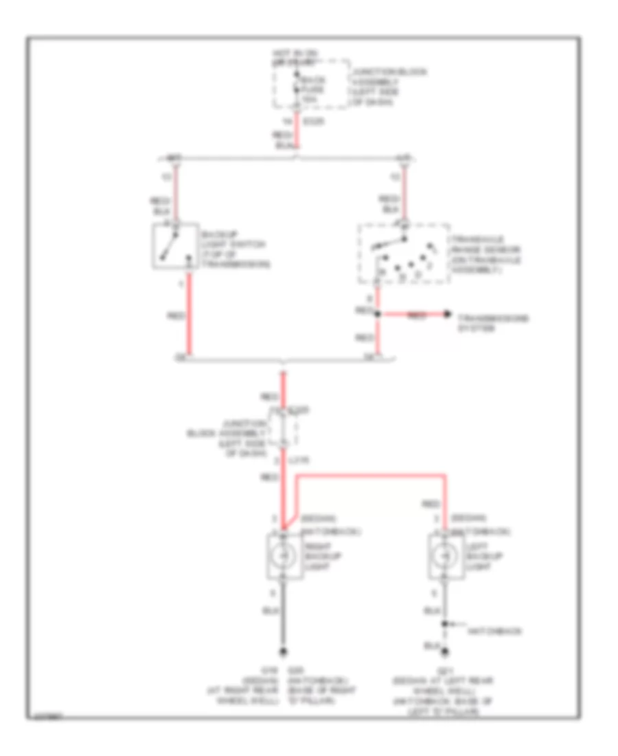
Backup Lamps Wiring Diagram for Suzuki SX4 Sport S 2010
List of elements for Backup Lamps Wiring Diagram for Suzuki SX4 Sport S 2010:
- (hatchback)
- (sedan)
- (sedan) (at right rear wheel well)
- A/t
- Back fuse 10a
- Backup light switch (top of transmission)
- E325
- G19 g20 (hatchback) (base of right "d" pillar)
- G21 (sedan: at left rear wheel well) (hatchback: base of left "d" pillar)
- Hatchback
- Hot in on or start
- Junction block assembly (left side of dash)
- L315
- Left backup light
- M/t
- Red
- Right backup light
- Transaxle range sensor (on transaxle assembly)
- Transmissions system
Exterior Lamps Wiring Diagram for Suzuki SX4 Sport S 2010
List of elements for Exterior Lamps Wiring Diagram for Suzuki SX4 Sport S 2010:
- (at right rear wheel well)
- (hatchback) (base of left "d" pillar)
- Anti-lock brakes system & shift interlock system
- Body control module (bcm) (left side of dash)
- Brake light switch (top of brake pedal assembly)
- Combination
- Combination switch
- E323
- E325
- Flasher relay
- G04
- G05
- G11 (behind right kick panel)
- G13 (behind left kick panel)
- G18 (under driver's seat)
- G19
- G19 (hatch back: base of right "d" pillar) (sedan: at right rear wheel well)
- G19 (sedan) (at right rear wheel well)
- G20 (at right rear wheel well)
- G20 (base of right "d" pillar)
- G21 (hatch back: base of left "d" pillar) (sedan: at left rear wheel well)
- G21 g19 (sedan) (at right rear wheel well)
- G23 (hatchback) (right side of tailgate)
- G271
- G272
- G9 (at right front strut tower)
- Gnd
- Hatchback
- Haz
- Hazard switch
- Head
- High mounted brake light
- Horn-haz fuse 15a
- Hot at all times
- Hot in on or start
- Instrument cluster system
- J/c g306
- J/c g309
- Junction block assembly (left side of dash)
- L314
- L315
- L393
- Left front position light
- Left front turn signal light
- Left rear combination light
- Left side marker light (if equipped)
- Left turn ind
- License plate light 1
- License plate light 2
- Light brake
- Light signal
- Light signal turn
- Light switch
- Light tail
- Lp-l
- Lp-r
- M152
- Marker light (if equipped)
- Meter
- Mtr fuse 10a
- Off
- On back window
- On trunk
- Right
- Right front position light
- Right front turn signal light
- Right rear combination light
- Right turn ind
- Sedan
- Side
- Stop fuse 10a
- Sw-l
- Sw-r
- Tail
- Tail fuse 10a
- Tail light relay
- Turn
- Turn signal switch
GROUND DISTRIBUTION
Ground Distribution Wiring Diagram for Suzuki SX4 Sport S 2010
List of elements for Ground Distribution Wiring Diagram for Suzuki SX4 Sport S 2010:
- (hatchback)
- 2wd/4wd switch
- 4wd control module
- A/b sdm
- A/b sdm (10 ch)
- Abs control module
- Acc socket
- Audio
- Battery
- Blower motor controller
- Blower motor relay
- Blower motor resistor
- Blower speed selector
- Body control module (bcm)
- Brake fluid level switch
- Ckp sensor
- Cmp sensor
- Combination meter
- Condenser cooling fan motor
- Contact coil
- Cpp cut switch (if equipped)
- Cvt control
- Cvt relay
- Dlc
- Driver seat heater
- Driver seat heater switch
- Driver side actuator state switch
- Driver side front power door lock switch
- Driver side power door lock main switch
- Driver side power mirror motor
- Driver side power window main switch
- Driver side request switch
- Elcm (if equipped)
- Engine control module (ecm)
- Esp control module
- Esp off switch
- Flasher relay
- Front fog light switch
- Front fog light switch (w/o illumination cancel switch)
- Fuel pump & fuel gauge
- G1 (left front of engine compt)
- G11 (behind right kick panel)
- G13 (behind left kick panel)
- G14 (behind right side of dash)
- G15 (under front passenger's seat)
- G16 (under front passenger's seat)
- G17 (under driver's seat)
- G18 (under driver's seat)
- G19 (hatch back: base of right "d" pillar) (sedan: at right rear wheel well)
- G2 (on transaxle)
- G20 (hatch back: base of right "d" pillar) (sedan: at right rear wheel well)
- G21 (hatch back: base of left "d" pillar) (sedan: at left rear wheel well)
- G22 (hatch back: base of left "d" pillar) (sedan: at left rear wheel well)
- G23 (hatchback) (right side of tailgate)
- G24 (top of fuel tank)
- G25 (at right "c" pillar)
- G3 (right side of engine)
- G4 (right side of engine)
- G6 (left rear of engine compt)
- G7 (left rear of engine compt)
- G8 (at right front strut tower)
- G9 (at right front strut tower)
- Hazard switch
- High mounted brake light
- High mounted light brake
- Hvac control unit
- Id controller
- Ignition coils 1 & 2
- Ignition coils 3 & 4
- Immobilizer control module
- Interior light (hatchback)
- Interior light (sedan)
- Keyless start system control module
- Left backup light
- Left brake light
- Left front fog light
- Left front position light
- Left front turn signal light
- Left headlight hi relay
- Left headlight lo relay
- Left rear turn signal light
- Left seat belt switch (10 ch)
- Left side marker
- Left side position sensor (10 ch)
- Left tail light
- License plate light 1
- License plate light 1 (hatchback)
- License plate light 1 (sedan)
- License plate light 2
- License plate light 2 (hatchback)
- License plate light 2 (sedan)
- Light switch
- Module
- Passenger seat heater
- Passenger seat heater switch
- Passenger side actuator state switch
- Passenger side power door lock sub switch (if equipped)
- Passenger side power mirror motor
- Passenger side request switch
- Power mirror switch
- Radiator fan motor
- Radiator fan relay 3
- Rear acc socket
- Rear defogger
- Rear defogger (hatchback)
- Rear defogger (sedan)
- Rear defogger switch
- Rear end door request switch
- Rear end door request switch (hatchback)
- Rear end power door lock solenoid
- Rear end power door lock solenoid (hatchback)
- Rear end power door lock switch
- Rear end power door lock switch (hatchback)
- Rear wiper & washer switch (hatchback)
- Rear wiper motor
- Rear wiper motor (hatchback)
- Rear wiper relay (hatchback)
- Right backup light (hatchback)
- Right backup light (sedan)
- Right brake light (hatchback)
- Right brake light (sedan)
- Right front fog light
- Right front position light
- Right front turn signal light
- Right headlight hi relay
- Right headlight lo relay
- Right rear turn signal light (hatchback)
- Right rear turn signal light (sedan)
- Right seat belt switch (10 ch)
- Right side marker
- Right tail light (hatchback)
- Right tail light (sedan)
- Select lever assembly
- Shift lock relay
- Spot light (hatchback)
- Spot light (sedan)
- Starting motor relay
- Steering angle sensor
- Trunk room lock solenoid (sedan)
- Turn signal switch
- Windshield wiper & washer switch
- Windshield wiper motor
- Yaw/g sensor
HEADLIGHTS
Headlights Wiring Diagram for Suzuki SX4 Sport S 2010
List of elements for Headlights Wiring Diagram for Suzuki SX4 Sport S 2010:
- Body control module (bcm) (left side of dash)
- Combination meter
- Combination switch
- Dimmer/ passing switch
- E381
- E382
- Flash
- Fr fog fuse 20a
- Front fog light relay (in fuse box 2)
- Front foglamp switch
- G04
- G05
- G06
- G13 (behind left kick panel)
- G241
- G271
- G272
- G6 (left rear of engine compt)
- G9 (at right front strut tower)
- H/l l fuse 15a
- H/l r fuse 15a
- Head
- High beam ind
- Hot at all times
- Individual circuit fuse box 1
- J/c g306
- Junction block assembly (left side of dash)
- Left front fog lamp
- Left headlight
- Left headlight high relay
- Left headlight low relay (left side of engine compt)
- Light switch
- Mtr fuse 10a
- Off
- Red
- Right front fog lamp
- Right headlight
- Right headlight high relay
- Right headlight low relay (left side of engine compt)
- Tail
- Tail fuse 10a
- Tail light relay
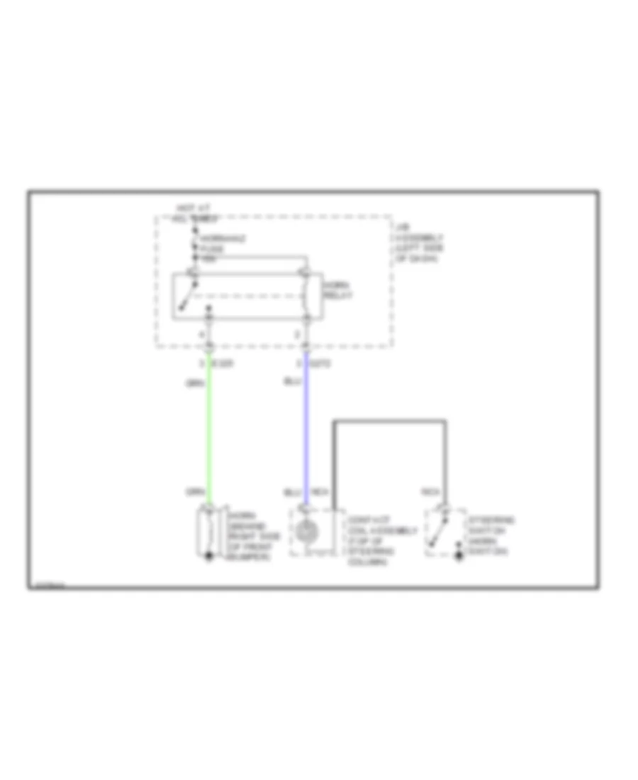
HORN
Horn Wiring Diagram for Suzuki SX4 Sport S 2010
List of elements for Horn Wiring Diagram for Suzuki SX4 Sport S 2010:
- Contact coil assembly (top of steering column)
- E325
- G272
- Horn (behind right side of front bumper)
- Horn relay
- Horn-haz fuse 15a
- Hot at all times
- J/b assembly (left side of dash)
- Nca
- Steering switch (horn switch)
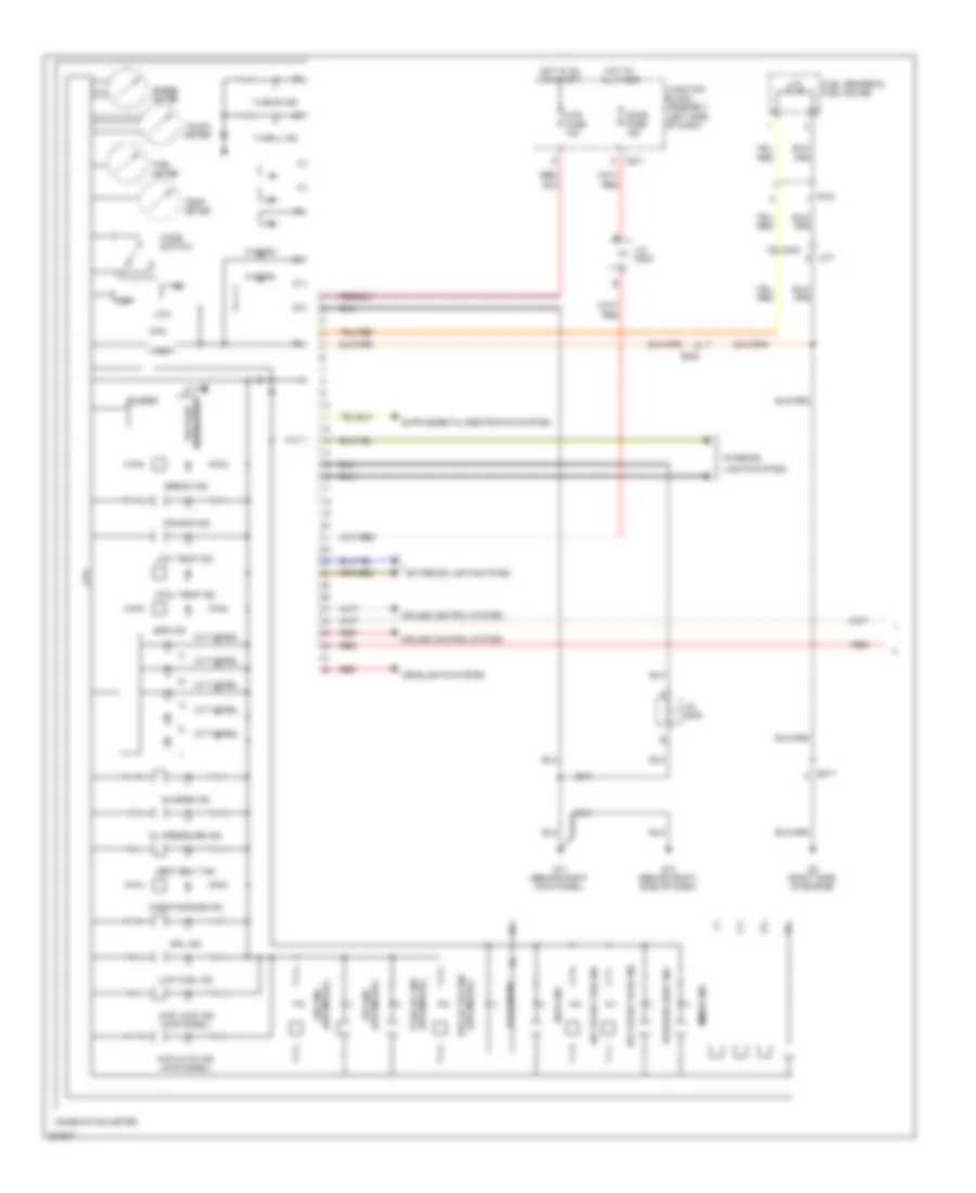
INSTRUMENT CLUSTER
Instrument Cluster Wiring Diagram (1 of 2) for Suzuki SX4 Sport S 2010
List of elements for Instrument Cluster Wiring Diagram (1 of 2) for Suzuki SX4 Sport S 2010:
- 4wd auto ind (4wd model)
- 4wd lock ind (4wd model)
- Abs ind (abs model)
- Air bag ind
- Break ind
- Buzzer
- Can
- Charge ind
- Check engine ind
- Combination meter
- Cool temp ind
- Cpu
- Cruise control system
- Cvt model
- Dome fuse 15a
- Door ind
- Drl ind
- E371
- E382
- Eps active ind (eps model)
- Eps ind
- Eps ind (eps model)
- Exterior lights system
- Fuel meter
- Fuel sender & fuel gauge
- G11 (behind right kick panel)
- G14 (behind right side of dash)
- G271
- G3 (right side of engine)
- G343
- Headlights system
- Hi beam ind
- High
- Hot at all times
- Hot in on or start
- Hot temp ind
- If eqpd
- Immobi ind
- Interior
- J/c g308
- J/c g309
- Junction block assembly (left side of dash)
- Key start red ind
- L371
- Lcd
- Lights system
- Low
- Low fuel ind
- Mode switch
- Mtr fuse 10a
- Oil pressure ind
- Position light ind
- R151
- Red
- Seat belt ind
- Speed meter
- Tacho meter
- Tcss off ind (eps model)
- Temp meter
- Turn-l ind
- Turn-r ind
- Voltage regulator
Instrument Cluster Wiring Diagram (2 of 2) for Suzuki SX4 Sport S 2010
List of elements for Instrument Cluster Wiring Diagram (2 of 2) for Suzuki SX4 Sport S 2010:
- Body control module (bcm) (left side of dash)
- Brake fluid level switch (at brake master cylinder)
- Driver side front door switch
- E371
- E381
- Engine oil pressure switch
- F l346
- G05
- G343
- G7 (left rear of engine compt)
- G9 (at right front strut tower)
- J/c g311
- J/c l346 & l347
- L347 d
- Left rear door switch
- Parking brake switch (under center console)
- Passenger side front door switch
- Red
- Right rear door switch
INTERIOR LIGHTS
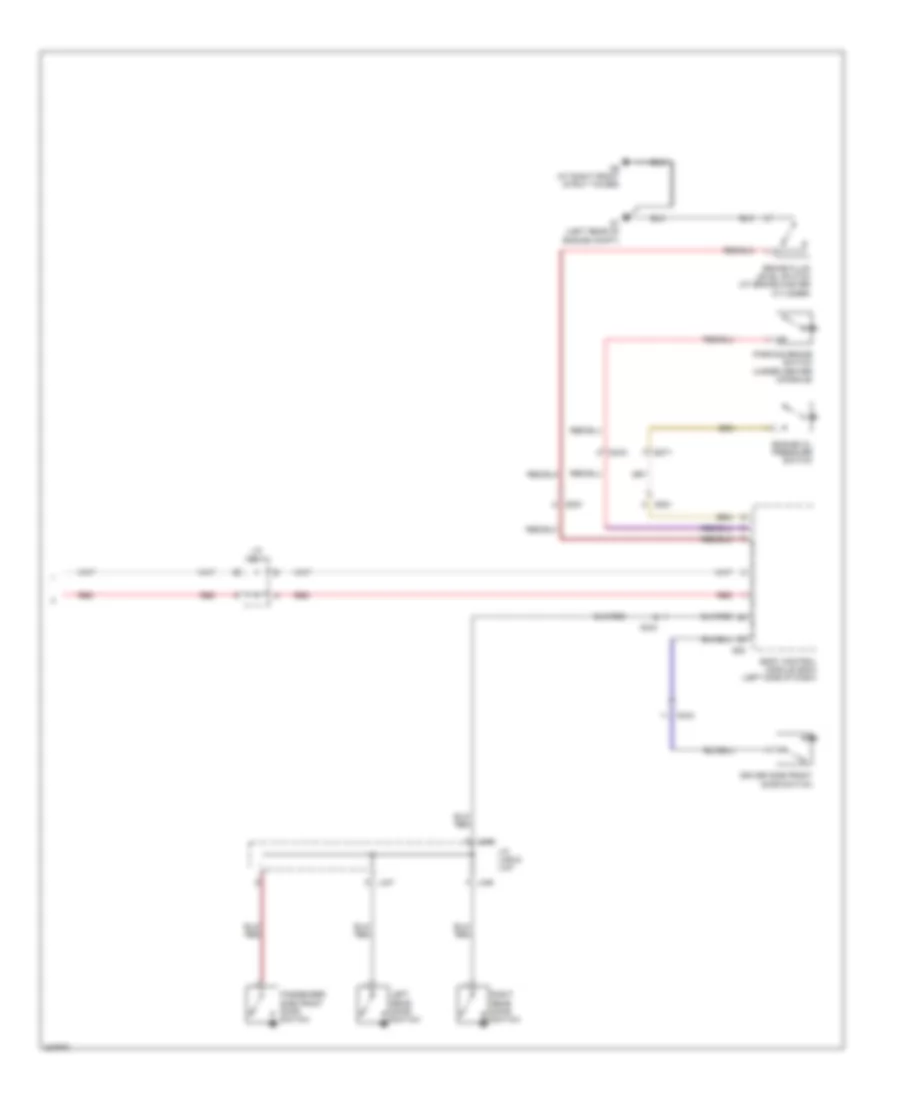
Courtesy Lamps Wiring Diagram for Suzuki SX4 Sport S 2010
List of elements for Courtesy Lamps Wiring Diagram for Suzuki SX4 Sport S 2010:
- (at left rear wheel well)
- (behind right kick panel) g11
- Back
- Body control module (bcm) (left side of dash)
- Diode (if equipped)
- Dome fuse 15a
- Door
- Driver front door switch
- G05
- G06
- G21
- G23 (right side of tailgate)
- G272
- G343
- Hatch-
- Hatch- back
- Hatchback
- Hot at all times
- Interior light
- J/c g309
- Junction block assembly (left side of dash)
- Junction connector
- K152
- L312
- L314
- L346
- L347
- L390
- Left rear door switch
- Luggage compartment light
- Off
- Passenger front door switch
- Rear end power door lock solenoid
- Right rear door switch
- Sedan
- Sedan hatchback
- Spot light
- Trunk room light
- Trunk room light switch
Instrument Illumination Wiring Diagram for Suzuki SX4 Sport S 2010
List of elements for Instrument Illumination Wiring Diagram for Suzuki SX4 Sport S 2010:
- 2wd/4wd switch
- Audio
- Body control module (bcm) (left side of dash)
- Combination switch (light switch)
- Driver seat heater switch
- E325
- Esp off switch
- Exterior lights system
- Front fog lamp switch
- G04
- G05
- G13 (behind left kick panel)
- G241
- G248
- G272
- G341
- Hazard switch
- Head
- Headlights system
- Hot at all times
- Hvac control module (automatic a/c) (center of dash)
- Hvac control unit (manual a/c) (center of dash)
- Instrument cluster system
- J/c g306
- J/c l346
- J/c l346 & l347
- Junction block assembly (left side of dash)
- L314
- L346
- L347
- Off
- Passenger seat heater switch
- Select lever assembly (a/t)
- Tail
- Tail fuse 10a
- Tail light relay
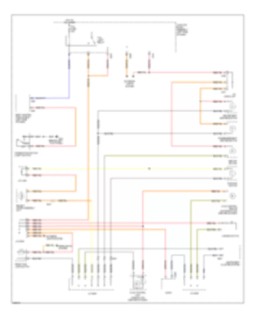
POWER DISTRIBUTION
Power Distribution Wiring Diagram (1 of 2) for Suzuki SX4 Sport S 2010
List of elements for Power Distribution Wiring Diagram (1 of 2) for Suzuki SX4 Sport S 2010:
- (left side of dash) junction block assembly
- 4wd control module, kls ecm, hvac control module, air intake actuator & hvac control unit
- A/b fuse 15a
- A/b sdm & occupancy classification ecm
- A/c compressor relay & a/c condenser cooling fan relay
- A/c fuse 20a
- Abs control module & esp control module
- Abs fuse 10a
- Abs mot fuse 40a
- Abs sol fuse 30a
- Acc
- At fuse 15a
- Back fuse 10a
- Battery
- Blw fuse 30a
- Brake light switch, cvt relay & power steering control module
- Combination meter, hazard switch & steering switch
- Cvt relay
- E311
- E312
- E323
- E324
- E325
- E382
- Fi fuse 15a
- Flasher relay
- Fr fog fuse 20a
- Front fog light relay
- Fuse 50a
- Fuse 80a
- G sensor & yaw/g sensor
- G271
- G272
- G273
- Generator
- Generator, ig coils 1-4, ecm & heated oxygen sensor
- H/l l fuse 15a
- H/l r fuse 15a
- Icm, bcm & id control module (if equipped)
- Ig coil fuse 15a
- Ig1 sig fuse 10a
- Ign fuse 50a
- Ignition switch
- Individual circuit fuse box 1
- Individual circuit fuse box 3 (sedan)
- J/b assembly (left side of dash)
- L312
- L313
- L315
- L317
- Left headlight, left headlight high & low relay
- Lock
- Main fuse box (behind battery)
- Main relay
- Mtr fuse 10a
- Radiator cooling fan relay 1 & 2
- Rdtr fuse 30a
- Rear defogger relay
- Rear washer motor
- Rear wiper motor
- Rear wiper relay (hatchback)
- Red
- Right headlight, right headlight high & low relay
- Rr def fuse 30a
- Rr wip fuse 15a
- St fuse 30a
- St sig fuse 10a
- Start
- Starting motor
- Starting motor relay
- Steering angle sensor
- Thr mot fuse 15a
- Throttle actuator control relay
- To j/b assembly (diagram 2 of 2)
- To p/w fuse (diagram 2 of 2)
- Transaxle range sensor & backup light switch
- Windshield washer motor
- Windshield wiper motor
- Windshield wiper/washer switch
- Wip fuse 30a
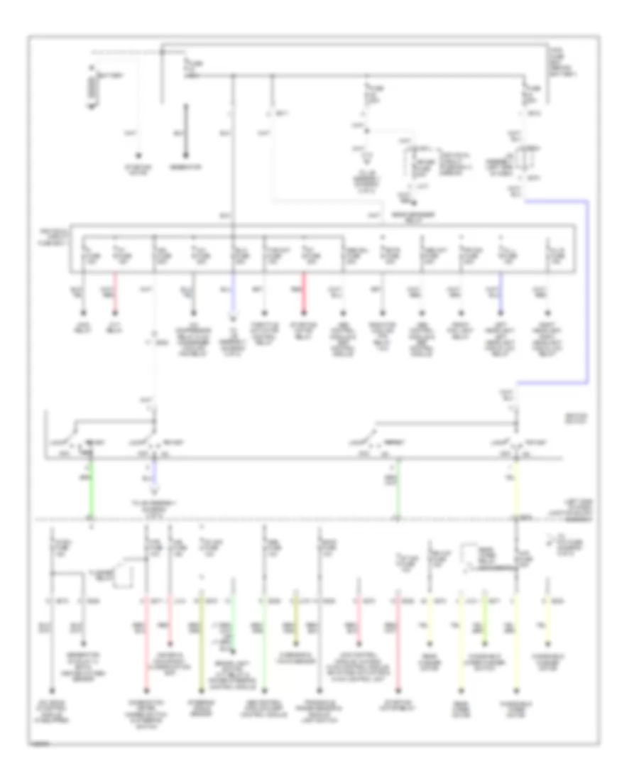
Power Distribution Wiring Diagram (2 of 2) for Suzuki SX4 Sport S 2010
List of elements for Power Distribution Wiring Diagram (2 of 2) for Suzuki SX4 Sport S 2010:
- (left side of dash) junction block assembly
- (not used)
- 4wd control module
- 4wd fuse 15a
- Acc 2 fuse 15a
- Acc fuse 15a
- Acc socket
- Bcm
- Blower motor relay
- Brake light switch
- D/l fuse 20a
- Dlc, bcm, main switch (key switch), kls ecm, combination meter, hvac control module, steering angle sensor, hazard switch, audio, hvac control unit & icm
- Dome fuse 15a
- Driver side seat heater switch & passenger side seat heater switch
- E323
- E324
- Ecm
- Esp off switch, select lever assembly, right & left tail light, left & right side marker lamp, audio, hazard warning light switch, left & right front position light, license plate light 1 & 2, hvac control unit, hvac control module , front fog light switch, driver & passenger seat heater switch & 2wd/4wd switch
- Flasher relay
- From ignition switch (diagram 1 of 2)
- From individual circuit fuse box 1 (diagram 1 of 2)
- From main fuse box (diagram 1 of 2)
- From rr def fuse e (diagram 2 of 2)
- From wip fuse d (diagram 1 of 2)
- G11 (behind right kick panel)
- G20 (sedan: at right rear wheel well) (hatch back: base of right "d" pillar)
- G271
- G272
- G273
- Horn haz fuse 15a
- Horn relay
- Ig2 sig fuse 10a
- Interior light & spot light
- Kls ecm & audio
- L312
- L314
- L315
- Left rear power window sub switch & right rear power window
- Luggage compartment light & trunk room light
- P/w fuse 30a
- Power mirror switch
- Power window main switch,
- Power window sub switch,
- Rear acc socket
- Rr def fuse (hatchback) 30a
- Rr def relay
- Rr fog fuse 15a
- S/h fuse 15a
- Stop fuse 10a
- Sub switch
- Tail fuse
- Tail light relay
- To 4wd fuse (diagram 2 of 2)
POWER DOOR LOCKS
Power Door Locks Wiring Diagram, with Smart Key System (1 of 2) for Suzuki SX4 Sport S 2010
List of elements for Power Door Locks Wiring Diagram, with Smart Key System (1 of 2) for Suzuki SX4 Sport S 2010:
- (base of left "d" pillar)
- (behind right kick panel) g11
- (under driver's
- (under driver's seat)
- Body control module (bcm) (left side of dash)
- Can
- Combination meter
- Computer data lines system
- Cpu
- D/l fuse 20a
- Door ind
- Driver side front door switch
- Driver side front power door lock switch
- Driver side power door lock main switch
- G04
- G05
- G06
- G17
- G17 (under driver's seat)
- G21
- G21 (base of left "d" pillar)
- G271
- G352
- Hatch- back
- Hot at all times
- Hot in on or start
- If equipped
- J/c g309
- J/c l346 & l347
- J215
- J216
- Junction block assembly (left side of dash)
- Keyless entry receiver (left side of dash)
- L346
- L347
- L374
- L381
- L382
- L390
- Left rear door switch
- Left rear power door lock motor
- Lock
- M152
- Mtr fuse 10a
- Off
- Passenger side front door switch
- Passenger side front power door lock motor
- Passenger side power door lock sub switch (if equipped)
- Pnk
- Rear end power door lock solenoid (hatch back)
- Rear end power door lock switch (hatch back)
- Red
- Regulator voltage
- Right rear door switch
- Right rear power door lock motor
- Seat)
- Security option
- Sedan
- Tpms receiver (under center console, at hand brake assembly)
- Trunk room lock solenoid
- Un- lock
Power Door Locks Wiring Diagram, with Smart Key System (2 of 2) for Suzuki SX4 Sport S 2010
List of elements for Power Door Locks Wiring Diagram, with Smart Key System (2 of 2) for Suzuki SX4 Sport S 2010:
- Acc 2 fuse 15a
- B g306
- B g307
- B g308
- Back fuse 10a
- Computer data lines system
- Dome fuse 15a
- Driver side
- Driver side actuator state switch
- Driver side door antenna
- G13 (behind left kick panel)
- G16 (under front passenger's seat)
- G17 (under driver's seat)
- G23 (right side of tailgate)
- G271
- G272
- G306 b
- G307 b
- G342
- Hatchback
- Hot at all times
- Hot in on or acc
- Hot in on or start
- Inside antenna
- J/c g306
- J/c g307
- J/c g308 & g307
- J/c g309
- J215
- J216
- Junction block assembly (left side of dash)
- Keyless smart system control
- L391
- Luggage antenna
- M152
- Main switch (key switch)
- Module (right side of dash)
- Passenger side actuator state switch
- Passenger side door antenna
- Passenger side request switch
- Rear end antenna
- Rear end door request switch
- Red
- Request switch
- Sedan
- Steering unit lock unit
- Trunk room request switch
Power Door Locks Wiring Diagram, without Smart Key System for Suzuki SX4 Sport S 2010
List of elements for Power Door Locks Wiring Diagram, without Smart Key System for Suzuki SX4 Sport S 2010:
- (base of left "d" pillar)
- (behind right kick panel) g11
- (under driver's
- (under driver's seat)
- Body control module (bcm) (left side of dash)
- Can
- Combination meter
- Computer data lines system
- Cpu
- D/l fuse 20a
- Door ind
- Driver side front door switch
- Driver side front power door lock switch
- Driver side power door lock main switch
- G04
- G05
- G06
- G17
- G17 (under driver's seat)
- G21
- G21 (base of left "d" pillar)
- G271
- G352
- Hatch- back
- Hot at all times
- Hot in on or start
- If equipped
- J/c g309
- J/c l346 & l347
- J215
- J216
- Junction block assembly (left side of dash)
- Keyless entry receiver (left side of dash)
- L346
- L347
- L374
- L381
- L382
- L390
- Left rear door switch
- Left rear power door lock motor
- Lock
- M152
- Mtr fuse 10a
- Off
- Passenger side front door switch
- Passenger side front power door lock motor
- Passenger side power door lock sub switch (if equipped)
- Pnk
- Rear end power door lock solenoid (hatch back)
- Rear end power door lock switch (hatch back)
- Red
- Regulator voltage
- Right rear door switch
- Right rear power door lock motor
- Seat)
- Security option
- Sedan
- Tpms receiver (under center console, at hand brake assembly)
- Trunk room lock solenoid
- Un- lock
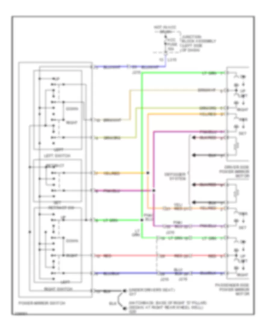
POWER MIRRORS
Power Mirrors Wiring Diagram for Suzuki SX4 Sport S 2010
List of elements for Power Mirrors Wiring Diagram for Suzuki SX4 Sport S 2010:
- (hatchback: base of right "d" pillar) (sedan: at right rear wheel well) g20
- (under driver's seat) g17
- Acc fuse 15a
- Defogger system
- Down
- Driver side power mirror motor
- Hot in acc or on
- J215
- J216
- Junction block assembly (left side of dash)
- L315
- Left
- Left switch
- Passenger side power mirror motor
- Power mirror switch
- Red
- Retract
- Retract sw
- Right
- Right switch
- Rtr
- Set
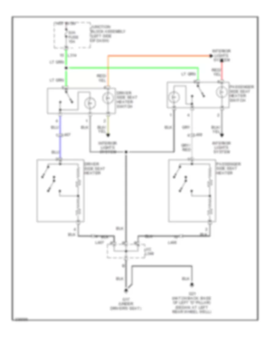
POWER SEATS
Power Seats Wiring Diagram for Suzuki SX4 Sport S 2010
List of elements for Power Seats Wiring Diagram for Suzuki SX4 Sport S 2010:
- Driver side seat heater
- Driver side seat heater switch
- G17 (under driver's seat)
- G21 (hatch back: base of left "d" pillar) (sedan: at left rear wheel well)
- Hot in on
- Interior lights system
- J/c l348
- Junction block assembly (left side of dash)
- L314
- L406
- L407
- Passenger side seat heater
- Passenger side seat heater switch
- S/h fuse 15a
POWER WINDOWS
Power Windows Wiring Diagram for Suzuki SX4 Sport S 2010
List of elements for Power Windows Wiring Diagram for Suzuki SX4 Sport S 2010:
- (hatch back:
- (under driver's
- At right rear wheel well)
- Auto circuit
- Base of right "d" pillar) (sedan:
- Down
- Driver side power window main switch
- G17
- G20
- Hot in on or start
- J/c l346 & l347
- J215
- J216
- J217
- J218
- Junction block assembly (left side of dash)
- L314
- L346
- L347
- Left front power window motor
- Left rear power window motor
- Left rear power window sub switch
- Lock
- Off
- P/w fuse 30a
- Red
- Right front power window motor
- Right front power window sub switch
- Right rear power window motor
- Right rear power window sub switch
- Seat)
RADIO
Radio Wiring Diagram for Suzuki SX4 Sport S 2010
List of elements for Radio Wiring Diagram for Suzuki SX4 Sport S 2010:
- (behind right side of dash) g14
- Acc 2 fuse 15a
- Antenna amplifier
- Audio
- Bcm (left side of dash)
- Center
- Combination meter
- Contact coil (top of steering column)
- Dome fuse 15a
- G04
- G241
- G248
- G267
- G271
- G341
- G343
- G348
- Hot at all times
- Hot in on or acc
- Ill
- Interior lights system
- J/c g306
- J/c g308
- J/c g312
- J215
- J216
- Junction block assembly (left side of dash)
- K154
- L381
- L382
- Left front speaker
- Left rear speaker
- Left rear tweeter (if equipped)
- Left tweeter (if equipped)
- Mode
- Mute
- Nca
- Pnk
- Red
- Right front speaker
- Right rear speaker
- Right rear tweeter (if equipped)
- Right tweeter (if equipped)
- Roof audio antenna
- Seek+
- Seek-
- Steering switch (audio control switch)
- Vol+
- Vol-
- W/ cruise control
- W/o cruise control
- Woofer (if equipped)
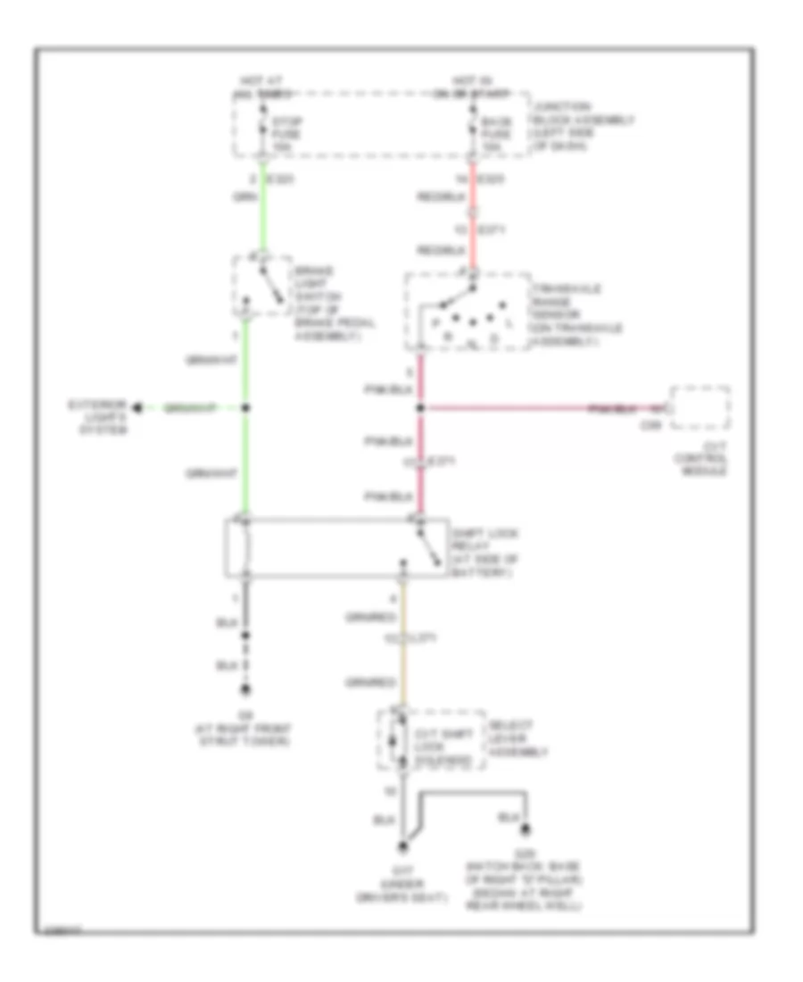
SHIFT INTERLOCK
Shift Interlock Wiring Diagram for Suzuki SX4 Sport S 2010
List of elements for Shift Interlock Wiring Diagram for Suzuki SX4 Sport S 2010:
- Back fuse 10a
- Brake light switch (top of brake pedal assembly)
- C09
- Cvt control module
- Cvt shift lock solenoid
- E323
- E325
- E371
- Exterior lights system
- G17 (under driver's seat)
- G20 (hatch back: base of right "d" pillar) (sedan: at right rear wheel well)
- G9 (at right front strut tower)
- Hot at all times
- Hot in on or start
- Junction block assembly (left side of dash)
- L371
- Select lever assembly
- Shift lock relay (at side of battery)
- Stop fuse 10a
- Transaxle range sensor (on transaxle assembly)
STARTING/CHARGING
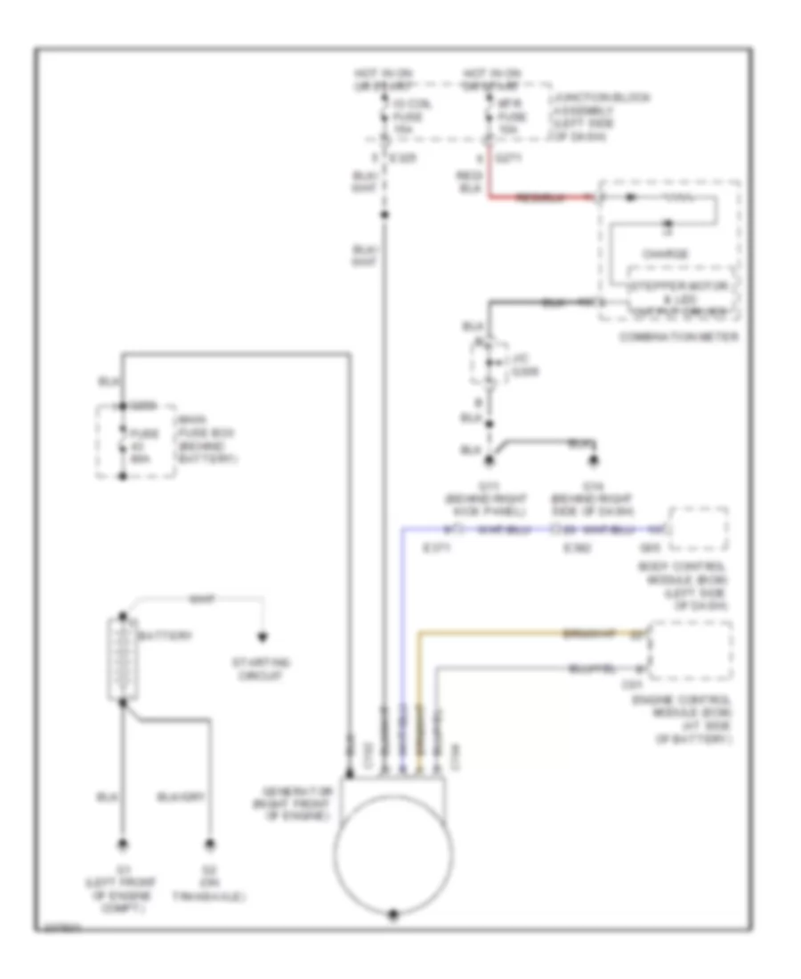
Charging Wiring Diagram for Suzuki SX4 Sport S 2010
List of elements for Charging Wiring Diagram for Suzuki SX4 Sport S 2010:
- (right front of engine)
- Battery
- Body control module (bcm) (left side of dash)
- C01
- C192
- C194
- C283
- Charge
- Combination meter
- E325
- E371
- E382
- Engine control module (ecm) (at side of battery)
- Fuse 80a
- G05
- G1 (left front of engine compt)
- G11 (behind right kick panel)
- G14 (behind right side of dash)
- G2 (on transaxle)
- G271
- Generator
- Hot in on or start
- Ig coil fuse 15a
- J/c g309
- Junction block assembly (left side of dash)
- Main fuse box (behind battery)
- Mtr fuse 10a
- Starting circuit
- Stepper motor & led output driver
Starting Wiring Diagram for Suzuki SX4 Sport S 2010
List of elements for Starting Wiring Diagram for Suzuki SX4 Sport S 2010:
- (right side of engine)
- A/t
- Acc
- Battery
- Charging circuit
- Clutch pedal (cpp) switch (at clutch pedal assembly)
- E01
- E311
- E312
- E324
- E325
- E371
- Engine control module (ecm) (at side of battery)
- Fuse 50a
- Fuse 80a
- G1 (left front of engine compt)
- G2 (on transaxle)
- G273
- G7 (left rear of engine compt)
- G9 (at right front strut tower)
- Ignition switch
- Individual circuit fuse box 1
- Junction block assembly (left side of dash)
- Lock
- M/t
- Main fuse box (behind battery)
- Red
- St fuse 30a
- St sig fuse 10a
- Start
- Starting motor
- Starting motor relay (left side of engine compt)
- Transaxle range sensor (on transaxle assembly)
SUPPLEMENTAL RESTRAINTS
Supplemental Restraints Wiring Diagram, with Advanced Air Bags (1 of 2) for Suzuki SX4 Sport S 2010
List of elements for Supplemental Restraints Wiring Diagram, with Advanced Air Bags (1 of 2) for Suzuki SX4 Sport S 2010:
- (behind right side of dash) (1st stage) passenger air bag (inflator) module
- (behind right side of dash) (2nd stage) passenger air bag (inflator) module
- (in left seat belt retractor assembly) left seat belt pretensioner
- (in right seat belt retractor assembly) right seat belt pretensioner
- (in steering wheel) driver air bag (inflator) module
- (under front passenger's seat)
- 1st stage
- 2nd stage
- A/b fuse 15a
- A/b sdm (center of vehicle floor)
- Check terminals
- Computer data lines system
- Contact coil assembly (top of steering column)
- Driver side air bag (inflator) module (in driver outer side of seat back)
- Driver side forward sensor (behind left headlight)
- G15
- G351
- G353
- Hot in on or start
- J/c l352
- J215
- J216
- Junction block assembly (left side of dash)
- L313
- L398
- L406
- L407
- Left side impact sensor (left lower side of vehicle chassis)
- Nca
- Occupant classification ecm (at front passenger seat)
- Passenger side air bag (inflator) module (in passenger outer side of seat back)
- Passenger side forward sensor (behind right headlight)
- Pnk
- Q132
- Q133
- Q134
- Red
- Right side impact sensor (right lower side of vehicle chassis)
- Shorting bar
Supplemental Restraints Wiring Diagram, with Advanced Air Bags (2 of 2) for Suzuki SX4 Sport S 2010
List of elements for Supplemental Restraints Wiring Diagram, with Advanced Air Bags (2 of 2) for Suzuki SX4 Sport S 2010:
- (behind left kick panel)
- (hatchback: top of left "c" pillar) (sedan: base of left "c" pillar) left side curtain air bag (inflator) module
- (hatchback: top of right "c" pillar) (sedan: base of right "c" pillar) right side curtain air bag (inflator) module
- (left side of dash) junction block assembly
- (sedan: at left rear wheel well) (hatch back: base of left "d" pillar) g22
- Air bag ind
- Bag off ind
- Bcm (left side of dash)
- C p u
- Combination
- Driver side position sensor
- Driver side seat belt switch
- G04
- G13
- G271
- G272
- Hazard switch
- Hot in on or start
- J/c g309
- J/c l353
- Junction block assembly (left side of dash)
- L313
- L406
- L407
- Left rear side forward sensor
- Meter
- Mtr fuse 10a
- Passenger
- Passenger air
- Passenger side seat belt switch
- Right rear side forward sensor
- Seat belt ind
- Shorting bar
Supplemental Restraints Wiring Diagram, without Advanced Air Bags for Suzuki SX4 Sport S 2010
List of elements for Supplemental Restraints Wiring Diagram, without Advanced Air Bags for Suzuki SX4 Sport S 2010:
- (left side of dash) junction block assembly
- A/b fuse 15a
- A/b sdm (center of vehicle floor)
- Air bag ind
- Bcm (left side of dash)
- Check terminal
- Combination meter
- Contact coil assembly (top of steering column)
- Cpu
- Data link connector (below left side of dash)
- Driver air bag (inflator) module (in steering wheel)
- G04
- G15 (under front passenger's seat)
- G271
- G272
- G344
- Hot in on or start
- J/c g308
- Junction block assembly (left side of dash)
- L313
- L372
- L399
- Left seat belt pretensioner (in left seat belt retractor assembly)
- Mtr fuse 10a
- Nca
- Passenger air bag (inflator) module (behind right side of dash)
- Red
- Right forward impact sensor
- Right seat belt pretensioner (in right seat belt retractor assembly)
- Seat belt ind
- W/ auto cruise
- W/o auto cruise
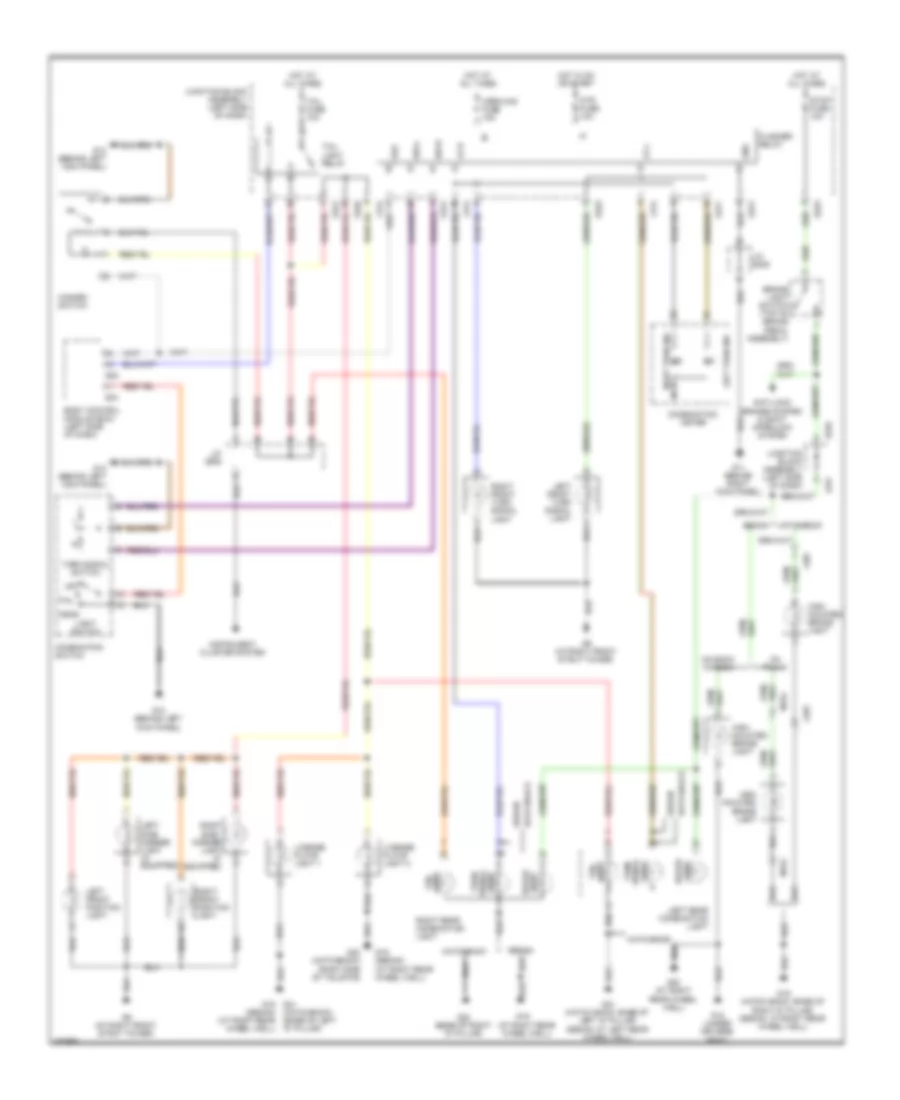
TRANSMISSION
4WD Wiring Diagram for Suzuki SX4 Sport S 2010
List of elements for 4WD Wiring Diagram for Suzuki SX4 Sport S 2010:
- (behind right kick panel)
- (under front passenger's seat)
- 2wd/4wd switch
- 4wd
- 4wd control module (center of dash)
- 4wd fuse 15a
- 4wd lock ind
- Back fuse 10a
- C p u
- Can
- Combination meter
- Computer data lines system
- Coupling air temperature sensor (right rear of vehicle chassis)
- Coupling solenoid (right rear of vehicle chassis)
- G11
- G11 (behind right kick panel)
- G16
- G271
- G272
- G343
- Hot at all times
- Hot in on or start
- Interior lights system
- J/c g306
- J/c g309
- J/c l348
- Junction block assembly (left side of dash)
- L397
- Lock
- Mtr fuse 10a
- Red
A/T Wiring Diagram (1 of 2) for Suzuki SX4 Sport S 2010
List of elements for A/T Wiring Diagram (1 of 2) for Suzuki SX4 Sport S 2010:
- (at side
- (behind right kick panel) g11
- (left rear of engine
- (left rear of engine compt) g7
- (left side
- (right side of engine)
- (right side of engine) g4
- Assembly
- At fuse 15a
- Back fuse 10a
- Block
- C09
- C10
- Can
- Circuit
- Combination meter
- Compt)
- Computer data lines system
- Cpu
- Cvt
- Cvt control module
- E325
- E371
- E381
- Exterior lights system
- Fuse box 1
- G271
- Hot at all times
- Hot in on or start
- Individual
- Input shaft speed sensor
- J/c g309
- Junction
- Junction block assembly (left side of dash)
- L371
- Mtr fuse 10a
- Of battery) shift lock relay
- Of dash)
- Output shaft speed sensor
- Pnk
- Pnk/
- Red
- Relay
- Transaxle range sensor
- Voltage regulator
- W/ cruise control
- W/o cruise control
A/T Wiring Diagram (2 of 2) for Suzuki SX4 Sport S 2010
List of elements for A/T Wiring Diagram (2 of 2) for Suzuki SX4 Sport S 2010:
- (top of
- Assembly
- Coil
- Contact
- Continuously
- Cvt
- Cvt shift lock solenoid
- Duty solenoid
- Fluid
- G13 (behind left kick panel)
- G16 (under front passenger's seat)
- G17 (under driver's seat)
- J/c g309
- J/c l348
- Manual mode switch
- Nca
- On/off solenoid
- Paddles)
- Pnk
- Pressure sensor
- Primary pressure sensor
- Primary solenoid
- Red
- Rom
- Secondary
- Secondary solenoid
- Select lever
- Shift down switch
- Shift down switch
- Shift up switch
- Steering column)
- Steering switch (shift
- Stepper motor 1
- Stepper motor 2
- Stepper motor 3
- Stepper motor 4
- Tempe- rature sensor
- Transmission
- Variable
- W/ cruise control
- W/o cruise control
WARNING SYSTEMS
Chime Wiring Diagram for Suzuki SX4 Sport S 2010
List of elements for Chime Wiring Diagram for Suzuki SX4 Sport S 2010:
- Body control module (bcm) (left side of dash)
- Combination meter
- Combination switch
- Cpu
- Dome fuse 15a
- Door ind
- Driver side door switch
- G04
- G05
- G11 (behind right kick panel)
- G12 (behind left kick panel)
- G13 (behind left kick panel)
- G271
- G343
- Head
- Hot at all times
- Hot in on or start
- J/c g307
- J/c g308
- J/c g309
- Junction block assembly (left side of dash)
- Light switch
- Main switch (key switch)
- Mtr fuse 10a
- Off
- Seat belt ind
- Tail
Tire Pressure Monitoring Wiring Diagram for Suzuki SX4 Sport S 2010
List of elements for Tire Pressure Monitoring Wiring Diagram for Suzuki SX4 Sport S 2010:
- Acc fuse 15a
- Body control module (bcm) (left side of dash)
- Can
- Combination meter
- Computer data lines system
- Driver side door switch
- E01
- E381
- Engine control module (ecm) (at side of battery)
- Esp control module (right rear of engine compt)
- G04
- G05
- G06
- G11 (behind right kick panel)
- G12 (behind left kick panel)
- G271
- G272
- G341
- G343
- High
- Hot in on or acc
- Hot in on or start
- Ig coil fuse 15a
- J/c g309
- J/c g311
- Junction block assembly (left side of dash)
- Left front tire pressure sensor (in left front wheel)
- Left rear tire pressure sensor (in left rear wheel)
- Low
- Micro controller
- Mtr fuse 10a
- Pnk
- Red
- Right front tire pressure sensor (in right front wheel)
- Right rear tire pressure sensor (in right rear wheel)
- Stepper motor & led output driver
- Tire pressure ind
- Tpms receiver (under center console, at hand brake assembly)
WIPER/WASHER
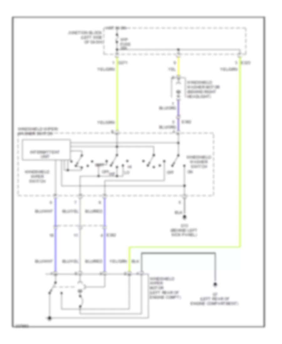
Front Wiper/Washer Wiring Diagram for Suzuki SX4 Sport S 2010
List of elements for Front Wiper/Washer Wiring Diagram for Suzuki SX4 Sport S 2010:
- E323
- E382
- G13 (behind left kick panel)
- G271
- G7 (left rear of engine compartment)
- Hot in on
- Int
- Intermittent unit
- Junction block (left side of dash)
- Mist
- Off
- Windshield washer motor (behind right headlight)
- Windshield washer switch
- Windshield wiper motor (left rear of engine compt)
- Windshield wiper switch
- Windshield wiper/ washer switch
- Wip fuse 30a
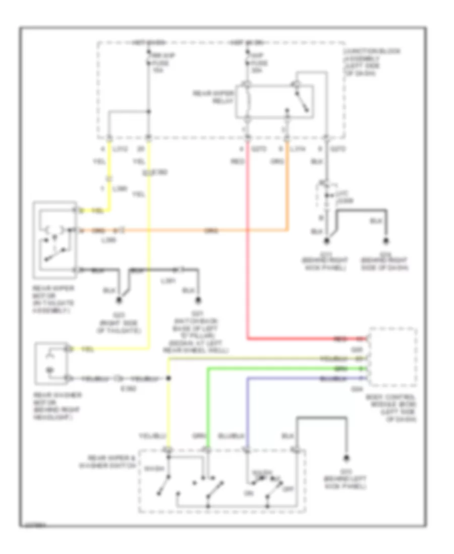
Rear Wiper/Washer Wiring Diagram for Suzuki SX4 Sport S 2010
List of elements for Rear Wiper/Washer Wiring Diagram for Suzuki SX4 Sport S 2010:
- (right side of tailgate)
- Body control module (bcm) (left side of dash)
- E382
- G04
- G05
- G11 (behind right kick panel)
- G13 (behind left kick panel)
- G14 (behind right side of dash)
- G21 (hatch back: base of left "d" pillar) (sedan: at left rear wheel well)
- G23
- G272
- Hot in on
- Int
- J/c g309
- Junction block assembly (left side of dash)
- L312
- L314
- L390
- L391
- Off
- Rear washer motor (behind right headlight)
- Rear wiper & washer switch
- Rear wiper motor (in tailgate assembly)
- Rear wiper relay
- Red
- Rr wip fuse 15a
- Wash
- Wash on+
- Wip fuse 30a