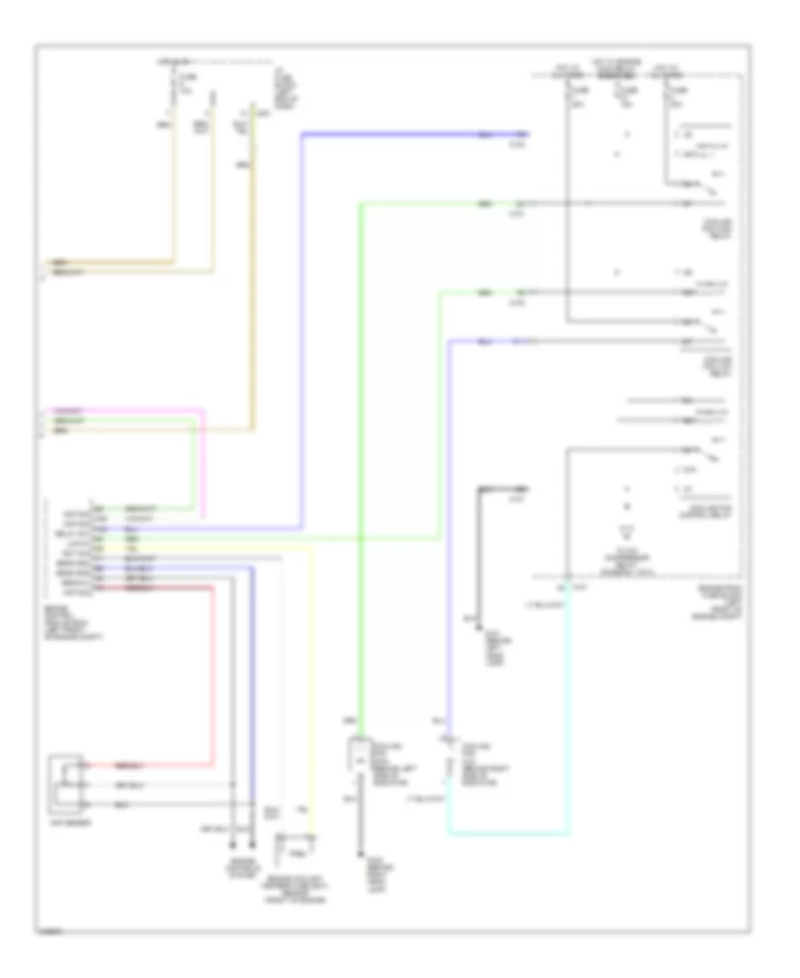
AIR CONDITIONING
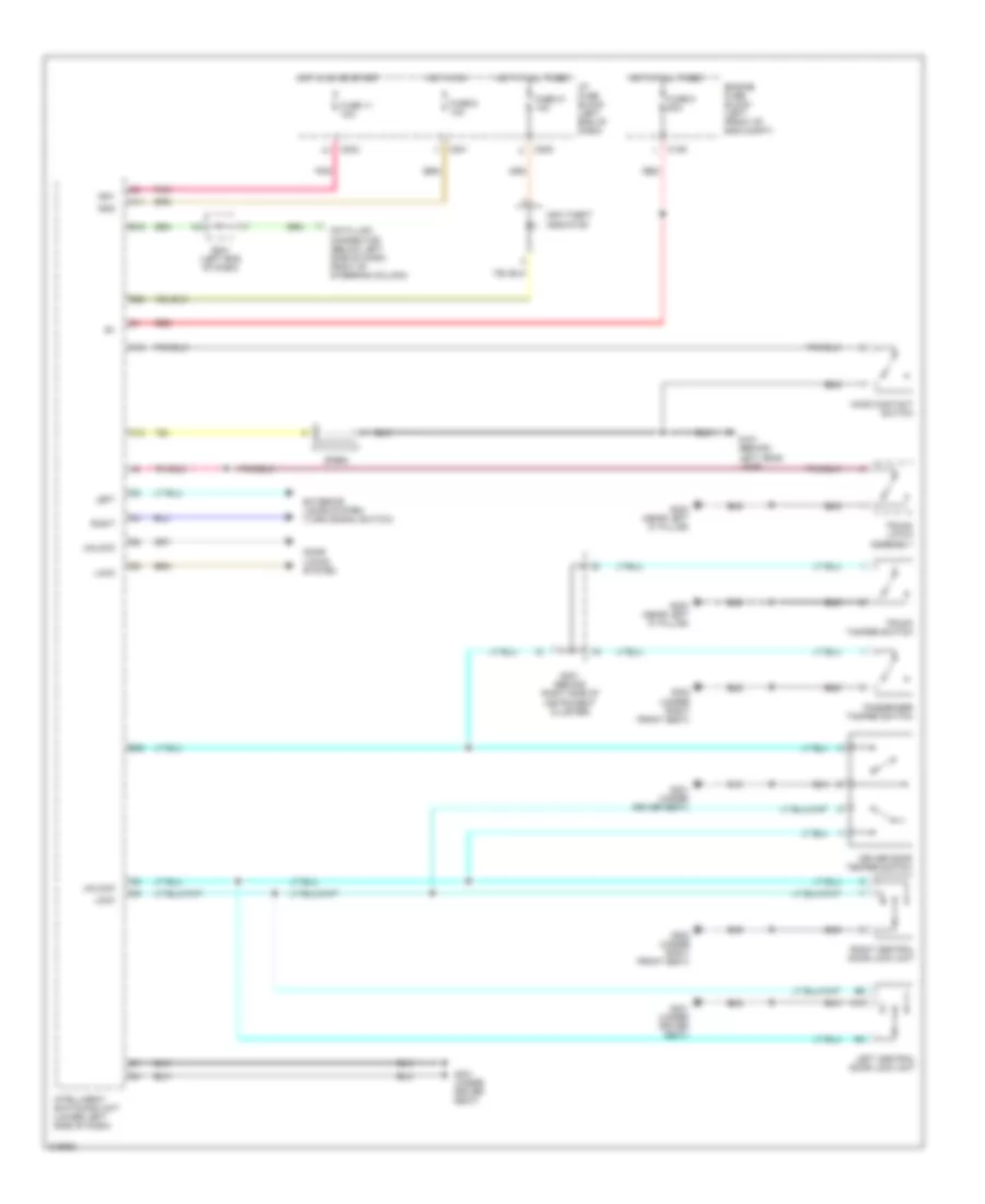
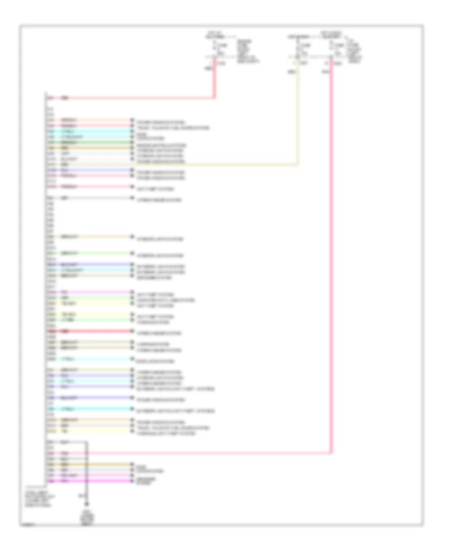
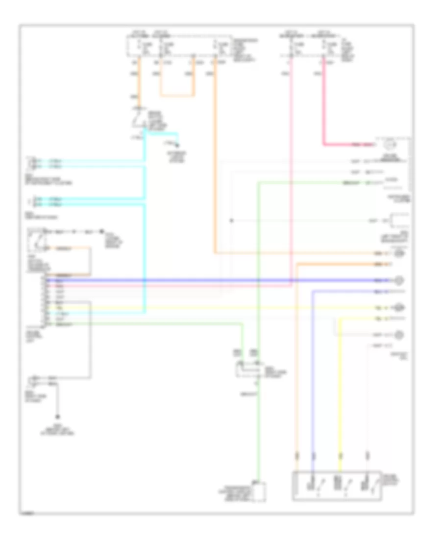
Automatic A/C Wiring Diagram (1 of 2) for Suzuki Verona LX 2005

List of elements for Automatic A/C Wiring Diagram (1 of 2) for Suzuki Verona LX 2005:
- A/c compressor
- A/c compressor relay
- A10
- A11
- A12
- A13
- A14
- A15
- A16
- Air mix door motor
- Ambient sensor (behind center of front bumper)
- Automatic temperature control
- B10
- B11
- B12
- B13
- B14
- B15
- B16
- B17
- B18
- B19
- B20
- Blower motor
- Blower relay
- C101
- C102
- C103
- C105
- C106
- C201
- Engine controls system
- Engine room fuse block (left front of engine compt)
- From cooling fan control relay (diagram 2 of 2)
- Fuse 10a
- Fuse 60a
- G102 (behind right head lamp)
- G202 (behind left of cigar lighter)
- G205 (behind ashtray)
- Hot at all times
- Hot in start & on
- I/p fuse block (left end of dash)
- In-car sensor
- Intake motor
- Interior lights system
- Max high relay
- Mode motor
- Pnk
- Power transistor
- S201 (left end of dash)
- Sun sensor
- Water sensor
- Wiper/washer system
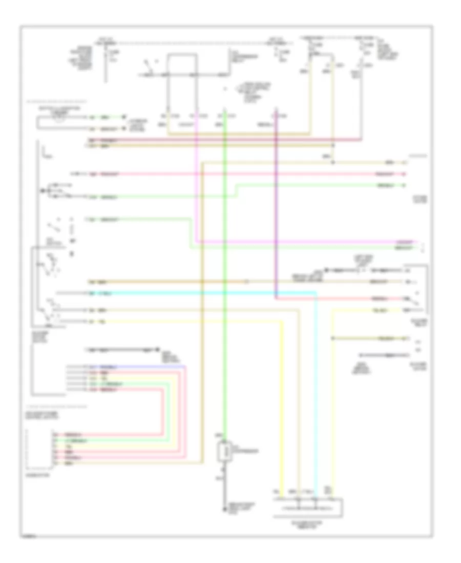
Automatic A/C Wiring Diagram (2 of 2) for Suzuki Verona LX 2005
List of elements for Automatic A/C Wiring Diagram (2 of 2) for Suzuki Verona LX 2005:
- 87a
- Acp sensor
- Acp sig
- C101
- C103
- C201
- Cooling fan aux (behind right side of radiator)
- Cooling fan control relay
- Cooling fan high relay
- Cooling fan low relay
- Cooling fan main (behind left side of radiator)
- Ect sig
- Engine control module (ecm) (left front of engine compt)
- Engine controls system
- Engine coolant temperature (ect) sensor (front of engine)
- Engine room fuse block (left front of engine compt)
- F11
- Fuse 10a
- Fuse 15a
- Fuse 20a
- G101 (behind left head lamp)
- G102 (behind right head lamp)
- Hot at all times
- Hot in on
- Hot w/ engine main relay energized
- I/p fuse block (left end of dash)
- Low/hi
- Relay sw
- Sens 5v
- Sens gnd
- To a/c compressor relay (diagram 1 of 2)
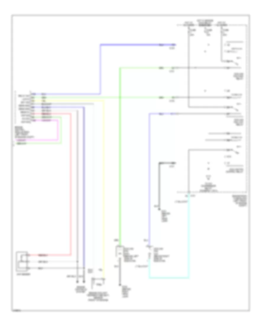
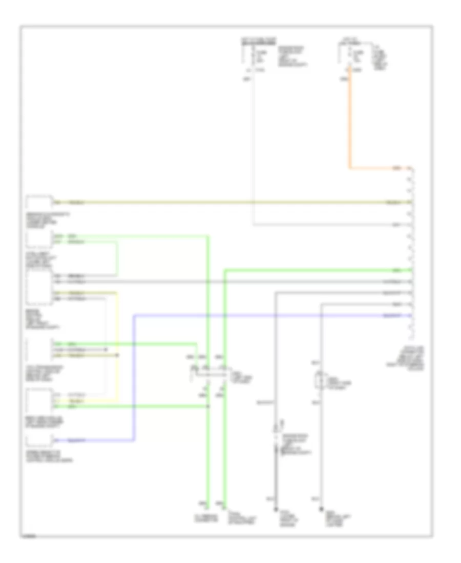
Manual A/C Wiring Diagram (1 of 2) for Suzuki Verona LX 2005
List of elements for Manual A/C Wiring Diagram (1 of 2) for Suzuki Verona LX 2005:
- (behind right head lamp) g102
- (left end of dash) s201
- A/c compressor
- A/c compressor relay
- A/c switch
- A11
- A12
- A13
- A14
- A15
- A17
- A19
- A20
- Air conditioner control switch
- Blower motor
- Blower motor resistor
- Blower motor switch
- Blower relay
- C101
- C102
- C103
- C106
- C201
- C204
- Engine room fuse block (left front of engine compt)
- From cooling fan control relay (diagram 2 of 2)
- Fuse 10a
- Fuse 20a
- Fuse 60a
- G202 (behind left of cigar lighter)
- G205 (behind ashtray)
- Hot at all times
- Hot in on
- I/p fuse block (left end of dash)
- Intake motor
- Interior lights system
- Mode motor
- Off
- Red
- Switch illumination (2 bulbs)
Manual A/C Wiring Diagram (2 of 2) for Suzuki Verona LX 2005
List of elements for Manual A/C Wiring Diagram (2 of 2) for Suzuki Verona LX 2005:
- 87a
- A/c sw
- Acp sensor
- Acp sig
- C101
- C103
- Cooling fan aux (behind right side of radiator)
- Cooling fan control relay
- Cooling fan high relay
- Cooling fan low relay
- Cooling fan main (behind left side of radiator)
- Ect sig
- Engine control module (ecm) (left front of engine compt)
- Engine controls system
- Engine coolant temperature (ect) sensor (front of engine)
- Engine room fuse block (left front of engine compt)
- F11
- Fuse 15a
- Fuse 20a
- G101 (behind left head lamp)
- G102 (behind right head lamp)
- Hot at all times
- Hot w/ engine main relay energized
- Low/hi
- Relay sw
- Sens 5v
- Sens gnd
- To a/c compressor relay (diagram 1 of 2)
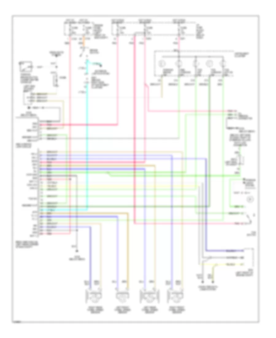
ANTI-LOCK BRAKES
Anti-lock Brakes Wiring Diagram for Suzuki Verona LX 2005
List of elements for Anti-lock Brakes Wiring Diagram for Suzuki Verona LX 2005:
- (below left side of dash, right of steering column) data link connector
- (left end of dash)
- (left end of dash) s201
- A13
- A14
- A16
- Abs warning ind
- Abs warning lamp module
- Abs wlp
- Abs/ebd wlp
- B14
- Bat (+)
- Bat (-)
- Brake switch
- Bws
- C102
- C105
- C15
- C201
- C202
- Can hi
- Can low
- Computer data lines system
- Diode
- Ebcm (abs module) (left rear corner of eng compt)
- Ebd wlp
- Ecm (left front of engine compt)
- Engine fuse block (left front of eng compt)
- Exterior lights system
- Fl (+)
- Fl (-)
- Fr (+)
- Fr (-)
- Fuse 10a
- Fuse 20a
- Fuse 60a
- G105 (below ebcm)
- Gnd
- Headlights system
- Hot at all times
- Hot in run or start
- I/p fuse block (left end of dash)
- Ign1
- Instrument cluster
- Interior lights system
- Kwp 2000
- Left front wheel speed sensor
- Left rear wheel speed sensor
- Oil feeding connector
- Parking brake ind
- Parking brake switch (under center console)
- Pnk
- Red
- Right front wheel speed sensor
- Right rear wheel speed sensor
- Rl+
- Rl-
- Rr+
- Rr-
- S201
- S301 (behind right side of instrument cluster)
- Stp
- Tcs active ind
- Tcs off ind
- Tcs sw
- Tcs switch
- Tcs warning ind
ANTI-THEFT
Anti-theft Wiring Diagram for Suzuki Verona LX 2005
List of elements for Anti-theft Wiring Diagram for Suzuki Verona LX 2005:
- A10
- A11
- A15
- Anti-theft indicator
- B19
- B20
- B30
- C106
- C12
- C201
- C202
- C205
- Data link connector (below left side of dash, right of steering column)
- Door locks system
- Driver door temper switch
- Engine fuse block (left front of eng compt)
- Exterior lamps system (turn signal switch)
- Fuse 11 10a
- Fuse 21 10a
- Fuse 5 60a
- Fuse 6 10a
- G101 (behind left head lamp)
- G301 (under driver seat)
- G302 (under right front seat)
- G303 (near left "c" pillar)
- Hood contact switch
- Hot at all times
- Hot in on
- Hot in on or start
- I/p fuse block (left end of dash)
- Ign1
- Ign2
- Intelligent switching unit (lower left side of dash)
- Left
- Left central door lock unit
- Lock
- Passenger tamper switch
- Pnk
- Red
- Right
- Right central door lock unit
- S201 (left end of dash)
- S301 (behind right side of instrument cluster)
- Siren
- Trunk latch assembly
- Trunk tamper switch
- Unlock
BODY CONTROL MODULES
Body Control Modules Wiring Diagram for Suzuki Verona LX 2005
List of elements for Body Control Modules Wiring Diagram for Suzuki Verona LX 2005:
- A10
- A11
- A12
- A13
- A14
- A15
- Anti-theft system
- B10
- B11
- B12
- B13
- B14
- B15
- B16
- B17
- B18
- B19
- B20
- B21
- B22
- B23
- B24
- B25
- B26
- B27
- B28
- B29
- B30
- C10
- C106
- C11
- C12
- C201
- C202
- Computer data lines system
- Defogger system
- Door locks system
- Engine controls system
- Engine fuse block (left front of eng compt)
- Exterior lights & anti-theft systems
- Exterior lights system
- Fuse 10a
- Fuse 60a
- G301 (under driver seat)
- Hot at all times
- Hot in run
- Hot in run & start
- I/p fuse block (left end of dash)
- Intelligent switching unit (lower left side of dash)
- Interior lights system
- Pnk
- Power windows system
- Red
- Trunk, tailgate, fuel doors system
- Warning & anti-theft system
- Warning system
- Wiper/washer system
COMPUTER DATA LINES
Computer Data Lines Wiring Diagram for Suzuki Verona LX 2005
List of elements for Computer Data Lines Wiring Diagram for Suzuki Verona LX 2005:
- A16
- B19
- C102
- C102 a1
- C205
- Data link connector (below left side of dash, right of steering column)
- Ebcm (abs module) (left rear corner of engine compt)
- Engine compt)
- Engine control module (left front of engine compt)
- Engine room fuse block (left front of c103
- Engine room fuse block (left front of engine compt)
- Fuse 10a
- Fuse 20a
- G103 (lower front of engine)
- G202 (behind left of cigar lighter)
- Hot at all times
- Hot w/ fuel pump relay energized
- I/p fuse block (left end of dash)
- Intelligent switching unit (lower left side of dash)
- Oil feeding connector
- S201 (left end of dash)
- S202 (right side of dash)
- Sensing & diagnostic module (sdm) (under center console)
- Speed sensitive power steering control module (ssps)
- Tcm (transmission control module) (behind left side of dash)
- Tpms control unit (if equipped)
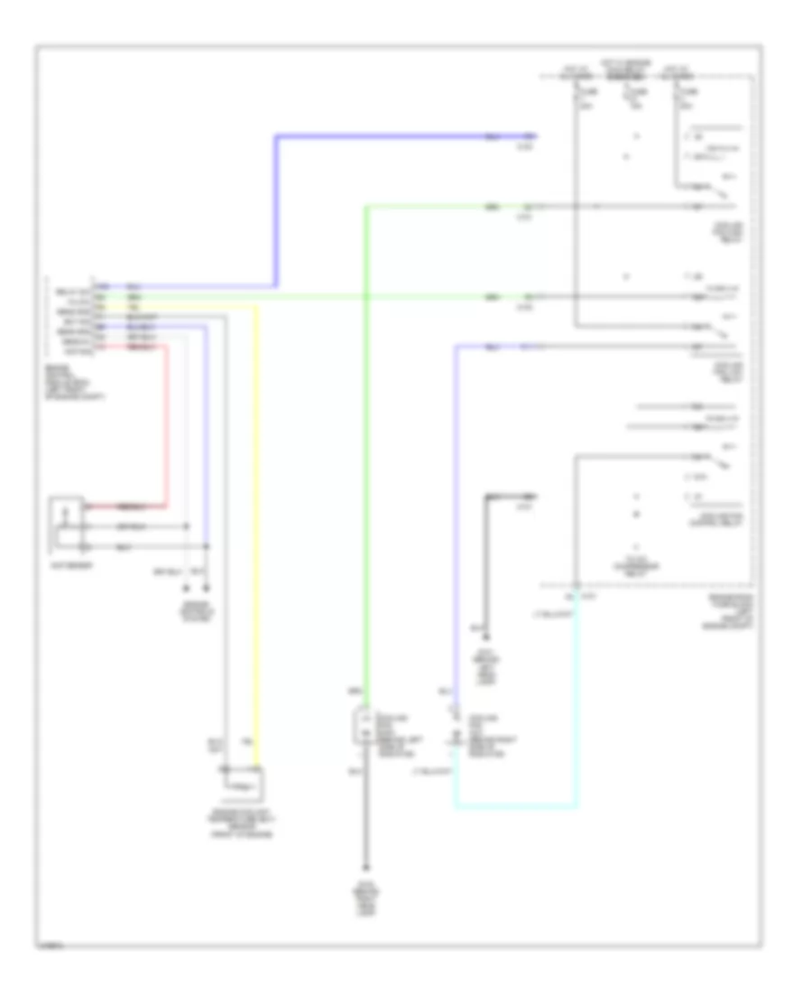
COOLING FAN
Cooling Fan Wiring Diagram for Suzuki Verona LX 2005
List of elements for Cooling Fan Wiring Diagram for Suzuki Verona LX 2005:
- 87a
- Acp sensor
- Acp sig
- C101
- C103
- Cooling fan aux (behind right side of radiator)
- Cooling fan control relay
- Cooling fan high relay
- Cooling fan low relay
- Cooling fan main (behind left side of radiator)
- Ect sig
- Engine control module (ecm) (left front of engine compt)
- Engine controls system
- Engine coolant temperature (ect) sensor (front of engine)
- Engine room fuse block (left front of engine compt)
- F11
- Fuse 15a
- Fuse 20a
- G101 (behind left head lamp)
- G102 (behind right head lamp)
- Hi/low
- Hot at all times
- Hot w/ engine main relay energized
- Relay sw
- Sens 5v
- Sens gnd
- To a/c compressor relay
CRUISE CONTROL
Cruise Control Wiring Diagram for Suzuki Verona LX 2005
List of elements for Cruise Control Wiring Diagram for Suzuki Verona LX 2005:
- Brake switch (lower left side of dash)
- C102
- C11
- C14
- C201
- C204
- C205
- Contact coil
- Cruise control switch
- Cruise control unit
- Cruise indicator
- Ecm (left front of engine compt)
- Engine room fuse block (left front of eng compt)
- Exterior lights system
- Fuse 10a
- Fuse 15a
- Fuse 20a
- Fuse 25a
- G103 (lower front of engine)
- G202 (behind left of cigar lighter)
- Hot at all times
- Hot in on or start
- I/p fuse block (left end of dash)
- Instrument cluster
- Main switch
- Mi-com
- Pnk
- Pnp switch (on side of transaxle)
- Resume switch
- S202 (right side of dash)
- S203 (center of dash)
- S301 (behind right side of instrument cluster)
- Switch set
- Transmission control module (behind left side of dash)
DEFOGGERS
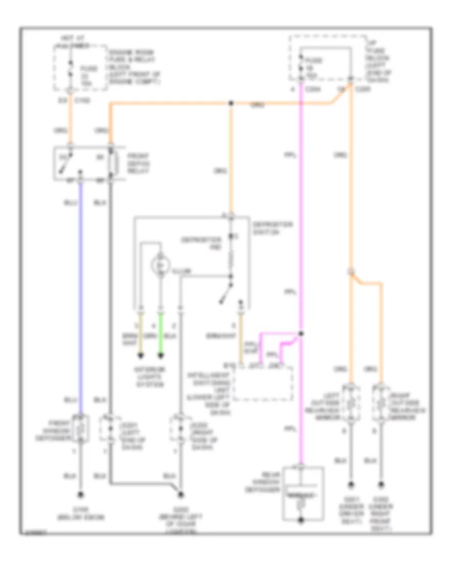
Defoggers Wiring Diagram for Suzuki Verona LX 2005
List of elements for Defoggers Wiring Diagram for Suzuki Verona LX 2005:
- B15
- C102 e9
- C204
- C205
- Defroster ind
- Defroster switch
- Engine room fuse & relay block (left front of engine compt)
- Front defog relay
- Front window defogger
- Fuse 10a
- Fuse 15a
- G105 (below ebcm)
- G202 (behind left of cigar lighter)
- G301 (under driver seat)
- G302 (under right front seat)
- Hot at all times
- I/p fuse block (left end of dash)
- Illum
- Intelligent switching unit (lower left side of dash)
- Interior lights system
- Left outside rearview mirror
- Module
- Rear window defogger
- Right outside rearview mirror
- S201 (left end of dash)
- S202 (right side of dash)
ELECTRONIC POWER STEERING
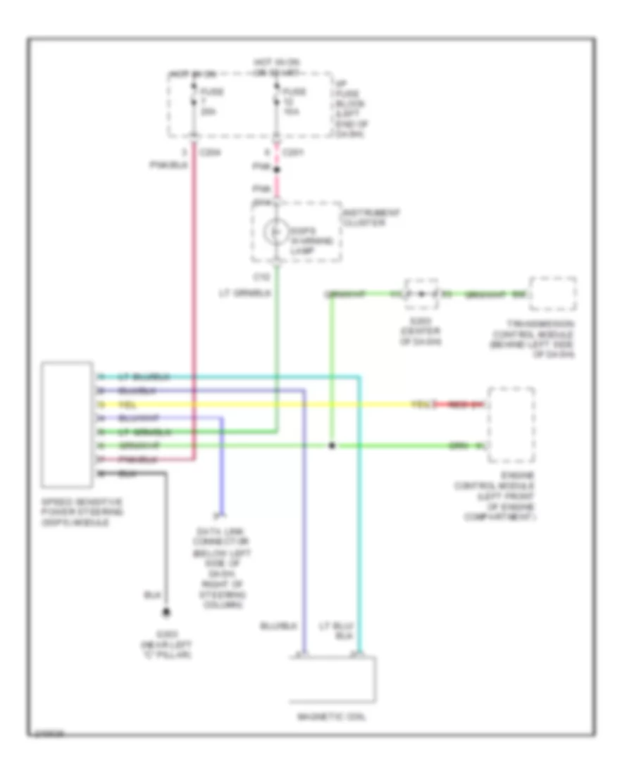
Electronic Power Steering Wiring Diagram for Suzuki Verona LX 2005
List of elements for Electronic Power Steering Wiring Diagram for Suzuki Verona LX 2005:
- (below left side of dash, right of steering column)
- C12
- C14
- C201
- C204
- Data link connector
- Engine control module (left front of engine compartment)
- Fuse 10a
- Fuse 20a
- G303 (near left "c" pillar)
- Hot in on
- Hot in on or start
- I/p fuse block (left end of dash)
- Instrument cluster
- Magnetic coil
- Pnk
- Red
- S203 (center of dash)
- Speed sensitive power steering (ssps) module
- Ssps warning lamp
- Transmission control module (behind left side of dash)
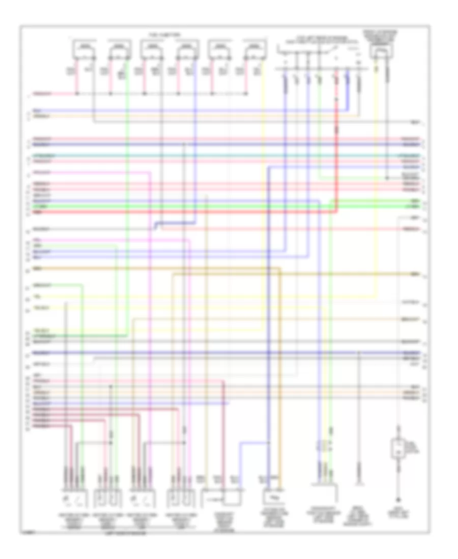
ENGINE PERFORMANCE
2.5L
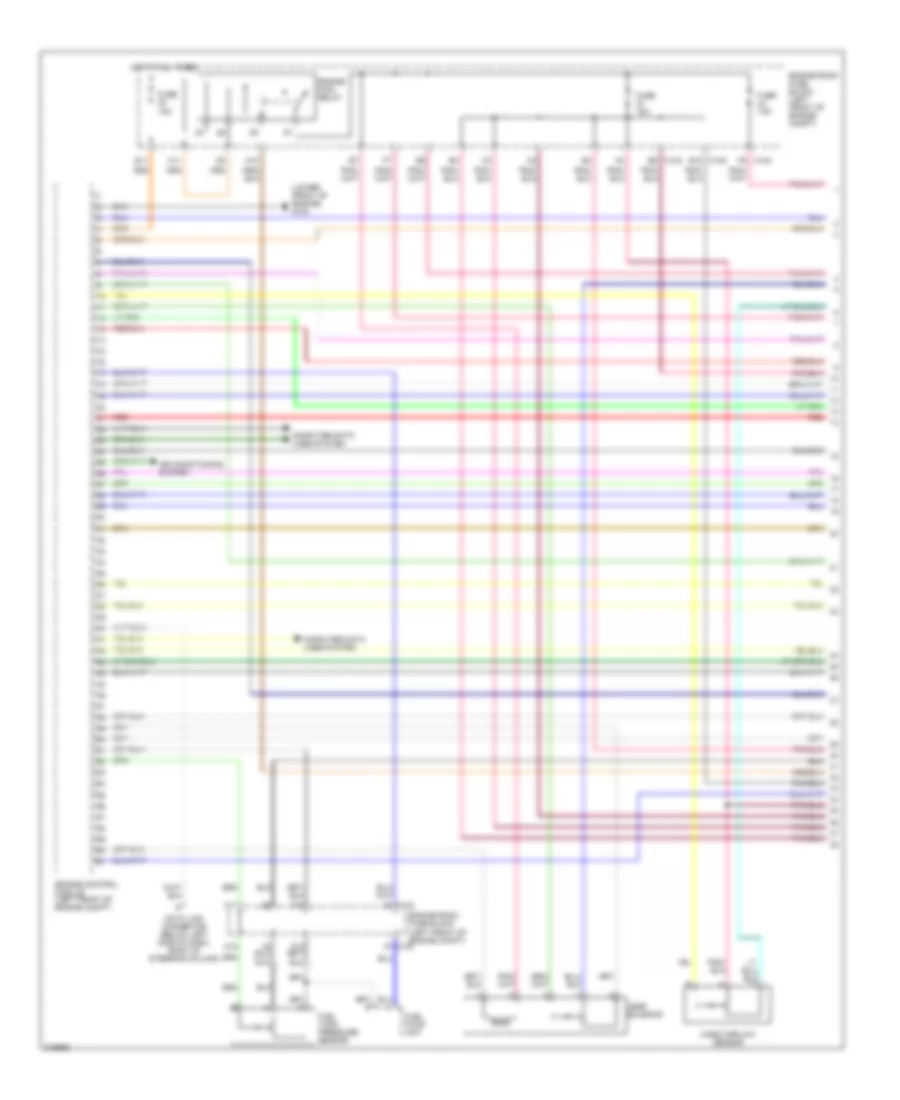
2.5L, Engine Performance Wiring Diagram (1 of 4) for Suzuki Verona LX 2005
List of elements for 2.5L, Engine Performance Wiring Diagram (1 of 4) for Suzuki Verona LX 2005:
- (lower front of engine) g103
- A10
- A11
- Air conditioning system
- B11
- B12 c102
- B5 c103
- C1 c102
- C103 f9
- C12
- Computer data lines system
- Data link connector (below left side of dash, right of steering column)
- Engine control module (left front of engine compt)
- Engine main relay
- Engine room fuse block (left front of engine compt)
- F1 c103
- F10
- F11
- Fuel pump unit
- Fuel tank pressure sensor
- Fuse 15a
- Hot at all times
- Legr solenoid
- Mass airflow sensor
- Red
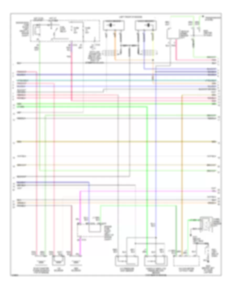
2.5L, Engine Performance Wiring Diagram (2 of 4) for Suzuki Verona LX 2005
List of elements for 2.5L, Engine Performance Wiring Diagram (2 of 4) for Suzuki Verona LX 2005:
- (front of engine) engine coolant temperature sensor
- (left side of engine)
- (top left rear of engine) main throttle idle actuator (mtia)
- Camshaft position sensor (front of engine)
- Crankshaft position sensor (left side of engine)
- Ebcm (w/ abs) (left rear corner of engine compt)
- Fuel injectors
- Fuel pump motor
- G303 (near left "c" pillar)
- Heated oxygen sensor 1 (ho2s 1) (down)
- Heated oxygen sensor 1 (ho2s 1) (up)
- Heated oxygen sensor 2 (ho2s 2) (down)
- Heated oxygen sensor 2 (ho2s 2) (up)
- Intake air temperature sensor (left side of engine)
- Red
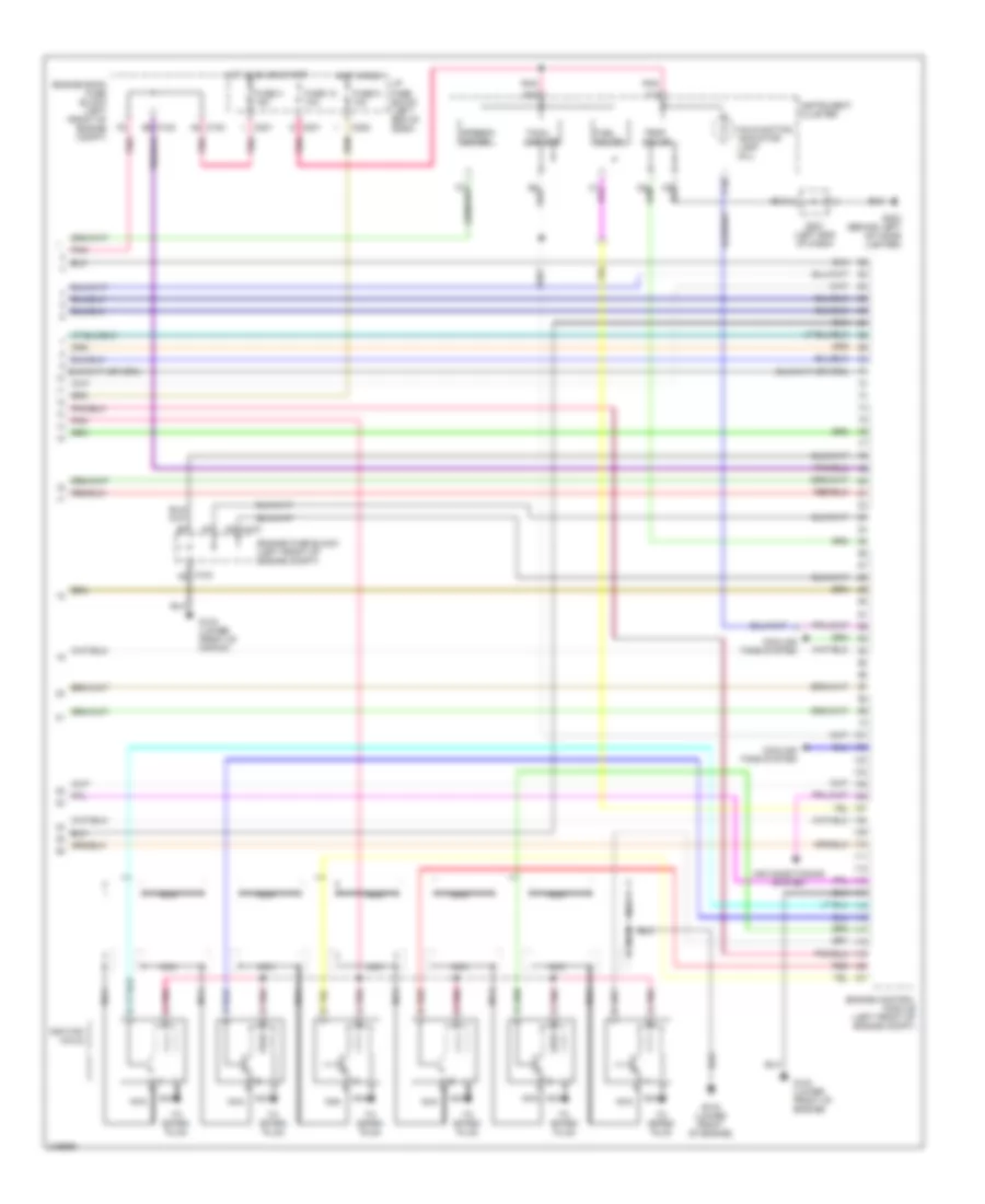
2.5L, Engine Performance Wiring Diagram (3 of 4) for Suzuki Verona LX 2005
List of elements for 2.5L, Engine Performance Wiring Diagram (3 of 4) for Suzuki Verona LX 2005:
- (left front of engine)
- A/c pressure (acp) sensor
- A/d converter (without abs)
- B2 c103
- C102 c9
- C102 d6
- C103 b9
- Data link connector (below left side of dash, right of steering column)
- Engine fuse block (left front of engine compt)
- Engine room fuse block (left front of engine compt)
- Esd solenoid
- Evap canister purge solenoid (top of engine)
- Fuel pump relay
- Fuse 20a
- G101 (behind left head lamp)
- G202 (behind left of cigar lighter)
- Hot at all times
- Hot in on or start
- Knock sensor 1
- Knock sensor 2
- Manifold absolute pressure (map) sensor (top rear of engine)
- Nca
- Pnk
- S201 (left end of dash)
- S203 (center of dash)
- Transmissions system
- Vehicle speed sensor (m/t)
- Vis solenoid
- Wheel speed sensor (m/t)
2.5L, Engine Performance Wiring Diagram (4 of 4) for Suzuki Verona LX 2005
List of elements for 2.5L, Engine Performance Wiring Diagram (4 of 4) for Suzuki Verona LX 2005:
- Air conditioning system
- B14
- C nca
- C10
- C102
- C103
- C103 a8
- C14
- C201
- C202
- C8 c103
- Cooling fans system
- Engine control module (left front of engine compt)
- Engine fuse block (left front of engine compt)
- Engine room fuse block (left front of engine compt)
- Fuel gauge
- Fuse 12 10a
- Fuse 3 15a
- Fuse 9 10a
- G103 (lower front of engine)
- G104 (lower front of engine)
- G202 (behind left of cigar lighter)
- Hot in on or start
- Hot in run
- I/p fuse block (left end of dash)
- Ignition coils
- Instrument cluster
- Malfunction indicator lamp (mil)
- Nca
- Pnk
- Pnk a
- Red
- Red b
- S201 (left end of dash)
- Speedo meter
- Tach- ometer
- Temp gauge
- To spark plug
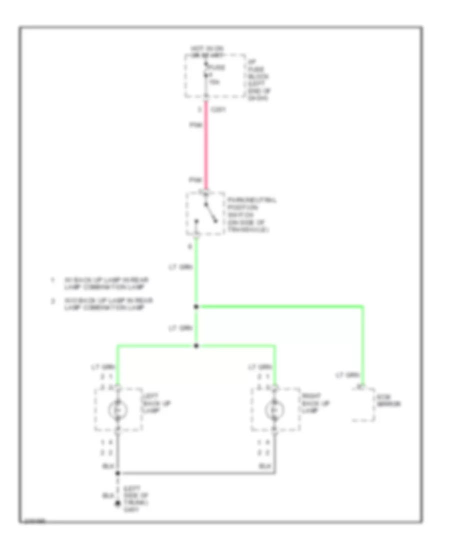
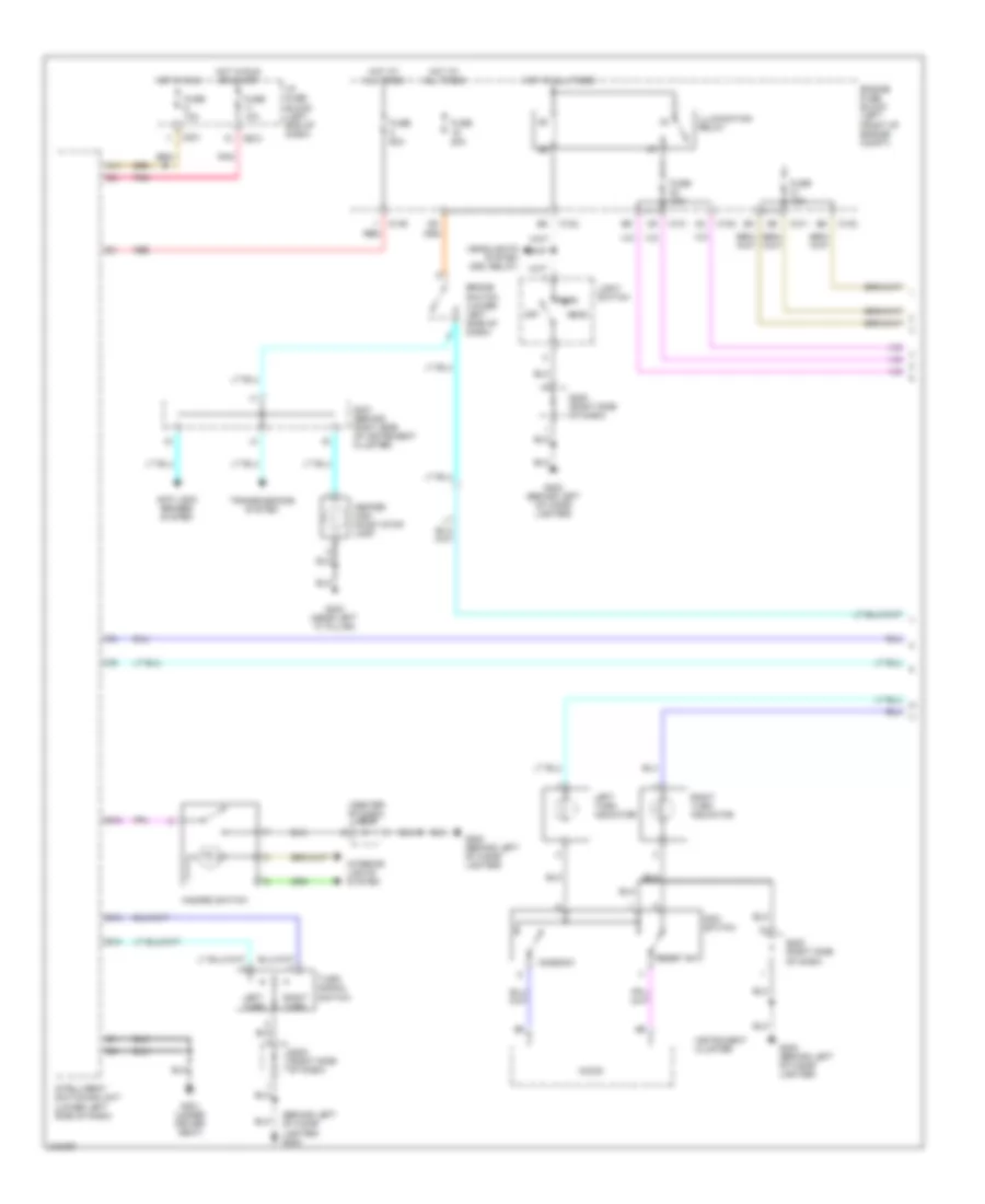
EXTERIOR LIGHTS
Back-up Lamps Wiring Diagram for Suzuki Verona LX 2005
List of elements for Back-up Lamps Wiring Diagram for Suzuki Verona LX 2005:
- (left side of trunk) g401
- C201
- Ecm mirror
- Fuse 15a
- Hot in on or start
- I/p fuse block (left end of dash)
- Left back up lamp
- Park/neutral position switch (on side of transaxle)
- Pnk
- Right back up lamp
- W/ back up lamp in rear lamp combination lamp
- W/o back up lamp in rear lamp combination lamp
Exterior Lamps Wiring Diagram (1 of 2) for Suzuki Verona LX 2005
List of elements for Exterior Lamps Wiring Diagram (1 of 2) for Suzuki Verona LX 2005:
- (behind left of cigar lighter) g202
- (center of dash) s203
- A11
- Anti-lock brakes system
- B13
- B14
- B18
- Brake switch (lower left side of dash)
- C101
- C102
- C106
- C201
- C202
- Center high mount stop lamp
- Engine fuse block (left front of engine compt)
- Fuse 10a
- Fuse 20a
- Fuse 60a
- G202 (behind left of cigar lighter)
- G301 (under driver seat)
- G303 (near left "c" pillar)
- Hazard switch
- Head
- Headlights system (drl relay)
- Hot at all times
- Hot in run
- Hot in run or start
- I/p fuse block (left end of dash)
- Illumination relay
- Instrument cluster
- Intelligent switching unit (lower left side of dash)
- Interior lights system
- Left turn
- Left turn indicator
- Light switch
- Micom
- Mode sw
- Odo switch
- Off
- Park
- Pnk
- Red
- Reset sw
- Right turn
- Right turn indicator
- S202 (right side of dash)
- S301 (behind right side of instrument cluster)
- Transmissions system
- Turn signal switch
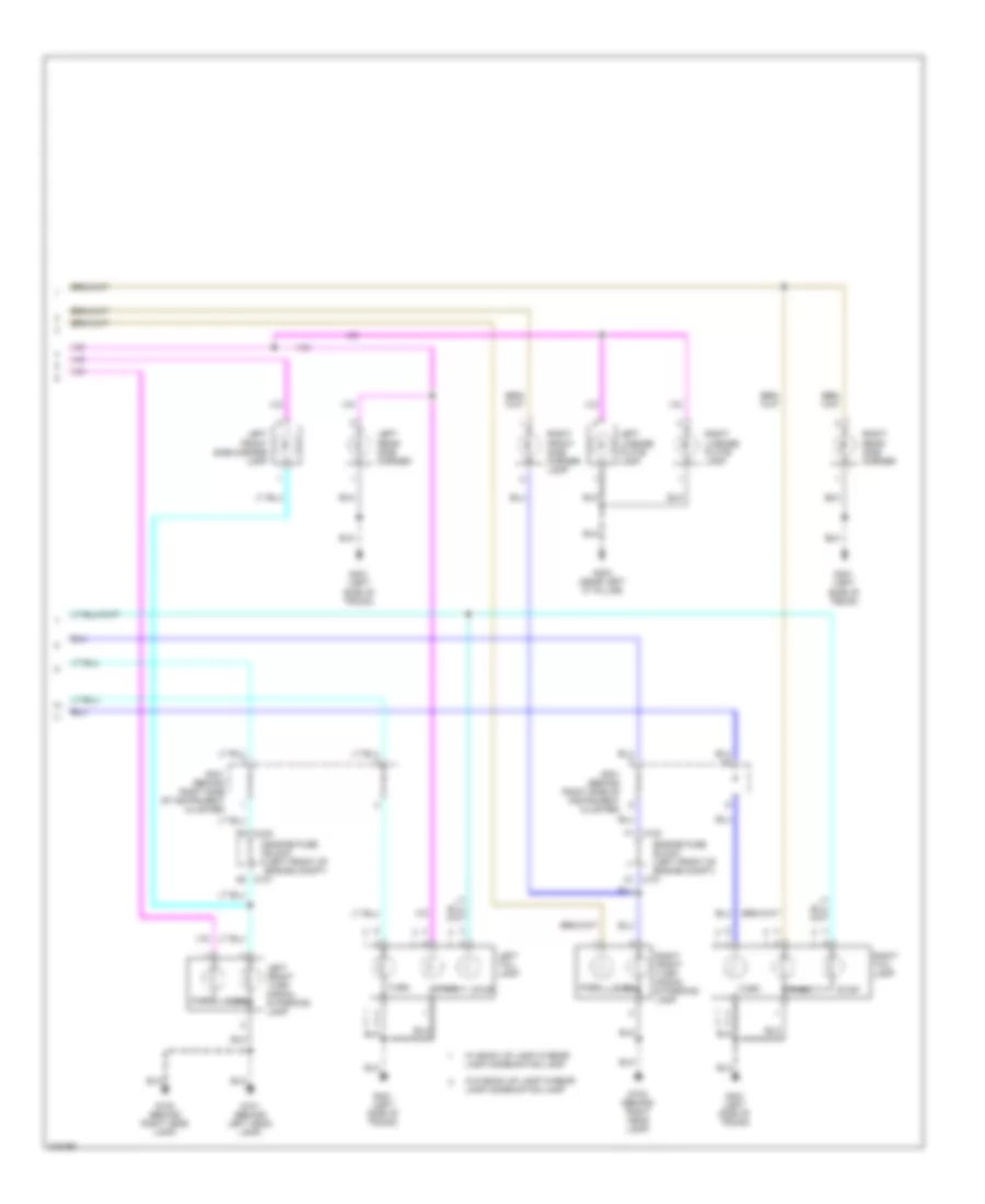
Exterior Lamps Wiring Diagram (2 of 2) for Suzuki Verona LX 2005
List of elements for Exterior Lamps Wiring Diagram (2 of 2) for Suzuki Verona LX 2005:
- A1 c101
- A9 c101
- Engine fuse block (left front of engine compt)
- F1 c102
- F9 c102
- G101 (behind left head lamp)
- G102 (behind right head lamp)
- G303 (near left "c" pillar)
- G401 (left side of trunk)
- Left front side marker lamp
- Left front turn signal & parking lamp
- Left license plate lamp
- Left rear side marker
- Left tail lamp
- Park
- Right front side marker lamp
- Right front turn signal & parking lamp
- Right license plate lamp
- Right rear side marker
- Right tail lamp
- S301 (behind right side of instrument cluster)
- Stop
- Turn
- W/ back up lamp in rear lamp combination lamp
- W/o back up lamp in rear lamp combination lamp
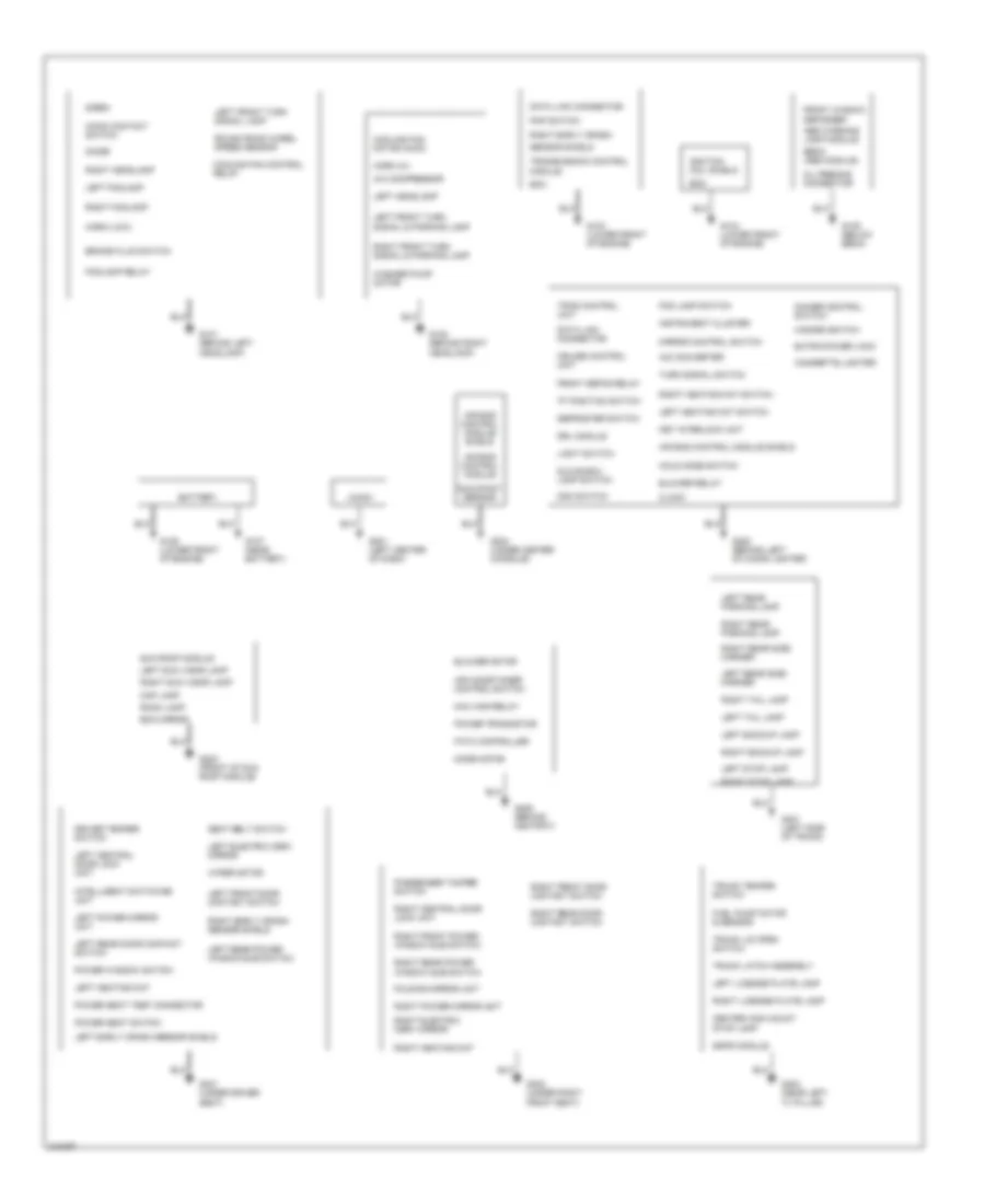
GROUND DISTRIBUTION
Ground Distribution Wiring Diagram for Suzuki Verona LX 2005
List of elements for Ground Distribution Wiring Diagram for Suzuki Verona LX 2005:
- "p" position switch
- A/c compressor
- A/d converter
- Abs warning lamp module
- Air bag control module
- Air bag control module shield
- Air conditioner control switch
- Audio
- Battery
- Blower motor
- Blower relay
- Brake fluid switch
- Center high mount stop lamp
- Cigarette lighter
- Clock
- Cooling fan control relay
- Cooling fan motor (main)
- Cruise control unit
- Data link connector
- Defroster switch
- Dimmer control switch
- Diode
- Driver temper switch
- Drl module
- Ebcm (abs module)
- Ecm
- Ecm mirror
- Extra power jack
- Fatc controller
- Fog lamp switch
- Foglamp relay
- Folding mirror unit
- Front defog relay
- Front window defogger
- Fuel pump motor & sensor
- G101 (behind left headlamp)
- G102 (behind right headlamp)
- G103 (lower front of engine)
- G104 (lower front of engine)
- G105 (below ebcm)
- G106 (lower front of engine)
- G107 (near battery)
- G201 (left center of dash)
- G202 (behind left of cigar lighter)
- G203 (front of sun roof module)
- G204 (under center console)
- G205 (behind ashtray)
- G301 (under driver seat)
- G302 (under right front seat)
- G303 (near left "c" pillar)
- G401 (left side of trunk)
- Glove box lamp switch
- Hazard switch
- Hold mode switch
- Hood contact switch
- Horn (hi)
- Horn (low)
- Ignition coil shield
- Instrument cluster
- Intelligent switching unit
- Key interlock unit
- Left backup lamp
- Left central door lock unit
- Left early crash sensor shield
- Left electric osrv mirror
- Left foglamp
- Left front door contact switch
- Left front turn signal & parking lamp
- Left front turn signal lamp
- Left headlamp
- Left heating mat
- Left heating mat switch
- Left license plate lamp
- Left power mirror unit
- Left rear door contact switch
- Left rear parking lamp
- Left rear power window sub switch
- Left rear side marker
- Left stop lamp
- Left sun visor lamp
- Left tail lamp
- Light switch
- Map lamp
- Max high relay
- Mirror control switch
- Mode motor
- Occupant sensor
- Odo switch
- Oil feeding connector
- Passenger tamper switch
- Pnp switch
- Power seat switch
- Power seat test connector
- Power transistor
- Power window switch
- Right backup lamp
- Right central door lock unit
- Right early crash
- Right early crash sensor shield
- Right electric osrv mirror
- Right foglamp
- Right front door contact switch
- Right front power window sub switch
- Right front turn signal & parking lamp
- Right headlamp
- Right heating mat
- Right heating mat switch
- Right license plate lamp
- Right power mirror unit
- Right rear door contact switch
- Right rear parking lamp
- Right rear power window sub switch
- Right rear side marker
- Right stop lamp
- Right sun visor lamp
- Right tail lamp
- Room lamp
- Rough road wheel speed sensor
- Seat belt switch
- Sensor shield
- Siren
- Ssps module
- Sun roof module
- Tpms control unit
- Transmission control module
- Trunk latch assembly
- Trunk lid open switch
- Trunk temper switch
- Turn signal switch
- Washer pump motor
- Wiper motor
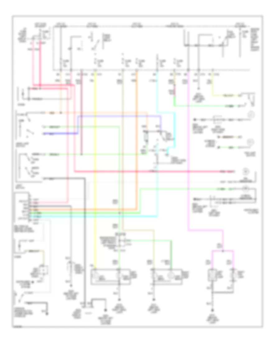
HEADLIGHTS
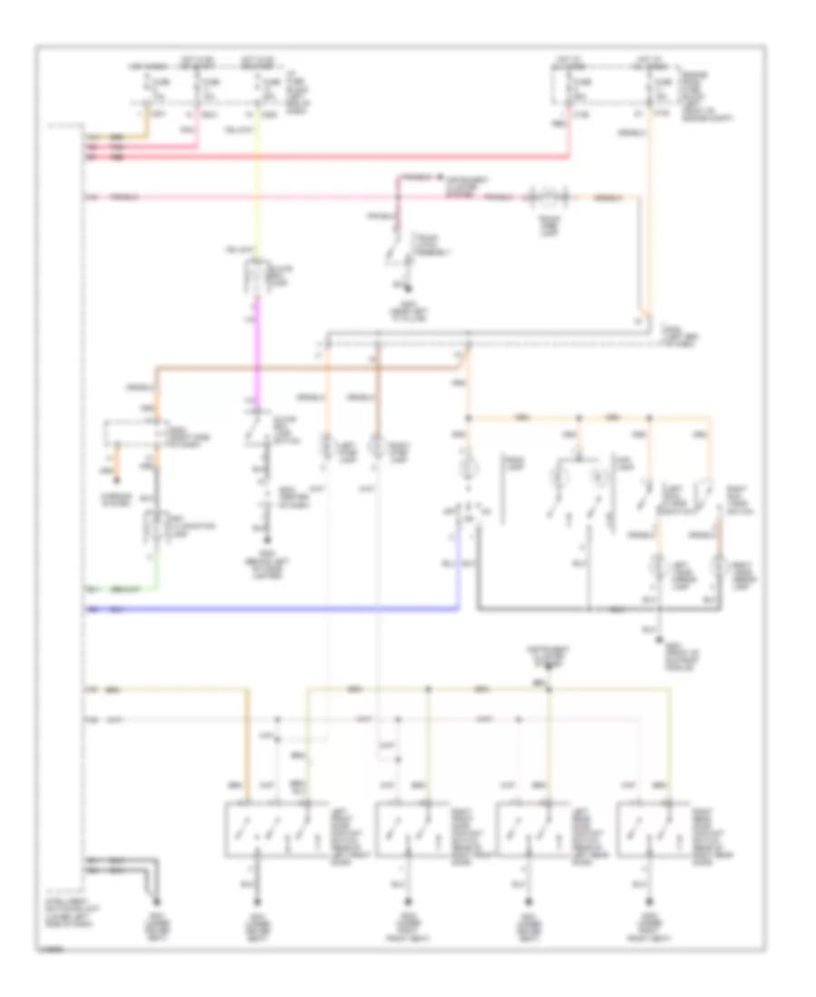
Headlights Wiring Diagram for Suzuki Verona LX 2005
List of elements for Headlights Wiring Diagram for Suzuki Verona LX 2005:
- A10
- A14
- A15
- B10 c101
- Bat+
- C10
- C101
- C102
- C102 e8
- C14
- C201
- D3 c102
- D9 c102
- Diode
- Drl cut relay
- Drl indicator
- Drl module (behind lower center of dash)
- Engine room fuse block (left front of engine comp)
- Engine room fuse block (left front of engine compt)
- Flash
- Fog lamp relay
- Fog lamp switch
- Fuse 10a
- Fuse 15a
- Fuse 20a
- G101 (behind left head lamp)
- G102 (behind right head lamp)
- G202 (behind left of cigar lighter)
- Gnd
- Head
- Head lamp relay
- Head lamp switch
- Hi beam indicator
- Hi in
- High
- High beam
- Hot at all times
- Hot in on or start
- Hot in park or head
- I/p fuse block (left end of dash)
- Ign1
- Ino out
- Instrument cluster
- Instrument cluster system
- Interior lights system
- Left fog lamp
- Left head lamp
- Light switch
- Low beam
- Low out
- Off
- Park
- Parking brake switch (under center console)
- Pnk
- Right fog lamp
- Right head lamp
- S201 (left end of dash)
- S202 (right side of dash)
HORN
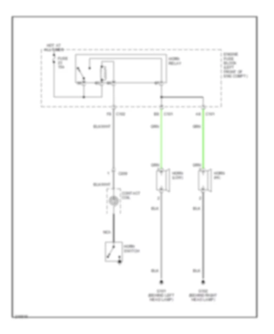
Horn Wiring Diagram for Suzuki Verona LX 2005
List of elements for Horn Wiring Diagram for Suzuki Verona LX 2005:
- C101
- C102
- C209
- Contact coil
- Engine fuse block (left front of eng compt)
- Fuse 15a
- G101 (behind left head lamp)
- G102 (behind right head lamp)
- Horn (hi)
- Horn (low)
- Horn relay
- Horn switch
- Hot at all times
- Nca
INSTRUMENT CLUSTER
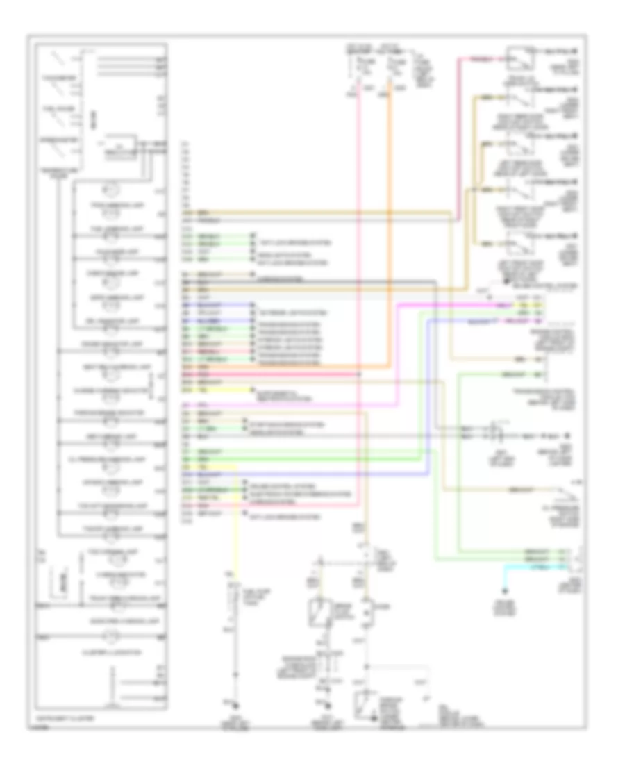
Instrument Cluster Wiring Diagram for Suzuki Verona LX 2005
List of elements for Instrument Cluster Wiring Diagram for Suzuki Verona LX 2005:
- 5v regulator
- A10
- A11
- A12
- A13
- A14
- A15
- A16
- Abs warning lamp
- Air bag warning lamp
- Anti-lock brakes system
- B10
- B11
- B12
- B13
- B14
- B15
- B16
- Brake fluid switch
- C10
- C101 e6
- C102 e12
- C11
- C12
- C13
- C14
- C15
- C16
- C201
- C205
- Charge warning indicator
- Check engine lamp
- Cluster illumination
- Cruise control system
- Cruise indicator lamp
- Diode
- Door open warning lamp
- Drl indicator lamp
- Drl module (behind lower center of dash)
- Electronic power steering system
- Engine control module (ecm) (left front of engine compt)
- Engine room fuse block (left front of engine compt)
- Exterior lights system
- Fuel gauge
- Fuel pump (on fuel tank)
- Fuel warning lamp
- Fuse 10a
- G101 (behind left head lamp)
- G202 (behind left of cigar lighter)
- G301 (under driver seat)
- G302 (under right front seat)
- G303 (near left "c" pillar)
- Headlights system
- Hi beam indicator
- Hold mode lamp
- Hot at all times
- Hot in on or start
- I/p fuse block (left end of dash)
- Instrument cluster
- Interior lights system
- Left front door contact switch (rear of left front door)
- Left rear door contact switch (rear of left door)
- Mi-com
- Oil pressure switch (right side of engine)
- Oil pressure warning lamp
- P r n d
- Parking brake indicator
- Parking brake switch (under center console)
- Pnk
- Right front door contact switch (rear of right front door)
- Right rear door contact switch (rear of right door)
- S201 (left end of dash)
- S203 (center of dash)
- Seat belt warning lamp
- Speedometer
- Ssps warning lamp
- Starting/charging system
- Tachometer
- Tcs active/warning lamp
- Tcs warning lamp
- Tcs/off warning lamp
- Temperature gauge
- Tpms warning lamp
- Transmission control module (tcm) (behind left side of dash)
- Transmissions system
- Trunk lid open switch
- Trunk open warning lamp
- Warning system
INTERIOR LIGHTS
Courtesy Lamps Wiring Diagram for Suzuki Verona LX 2005
List of elements for Courtesy Lamps Wiring Diagram for Suzuki Verona LX 2005:
- A11
- B11
- C102
- C106
- C201
- C202
- C205
- Engine room fuse block (left front of engine compt)
- Fuse 10a
- Fuse 15a
- Fuse 20a
- Fuse 60a
- G202 (behind left of cigar lighter)
- G203 (front of sun roof module)
- G301 (under driver seat)
- G302 (under right front seat)
- G303 (near left "c" pillar)
- Glove box lamp
- Glove box lamp switch
- Hot at all times
- Hot in on or start
- Hot in run
- I/p fuse block (left end of dash)
- Instrument cluster system
- Intelligent switching unit (lower left side of dash)
- Key illumination lamp
- Left front door contact switch (rear of left front door)
- Left rear door contact switch (rear of left rear door)
- Left step lamp
- Left sun visor switch
- Left visor mirror lamp
- Map lamp
- Off
- Pnk
- Red
- Right front door contact switch (rear of right front door)
- Right rear door contact switch (rear of right rear door)
- Right step lamp
- Right sun visor switch
- Right visor mirror lamp
- Room lamp
- S202 (right side of dash)
- S203 (center of dash)
- S302 (left end of dash)
- Trunk latch assembly
- Trunk open lamp
- Warning system
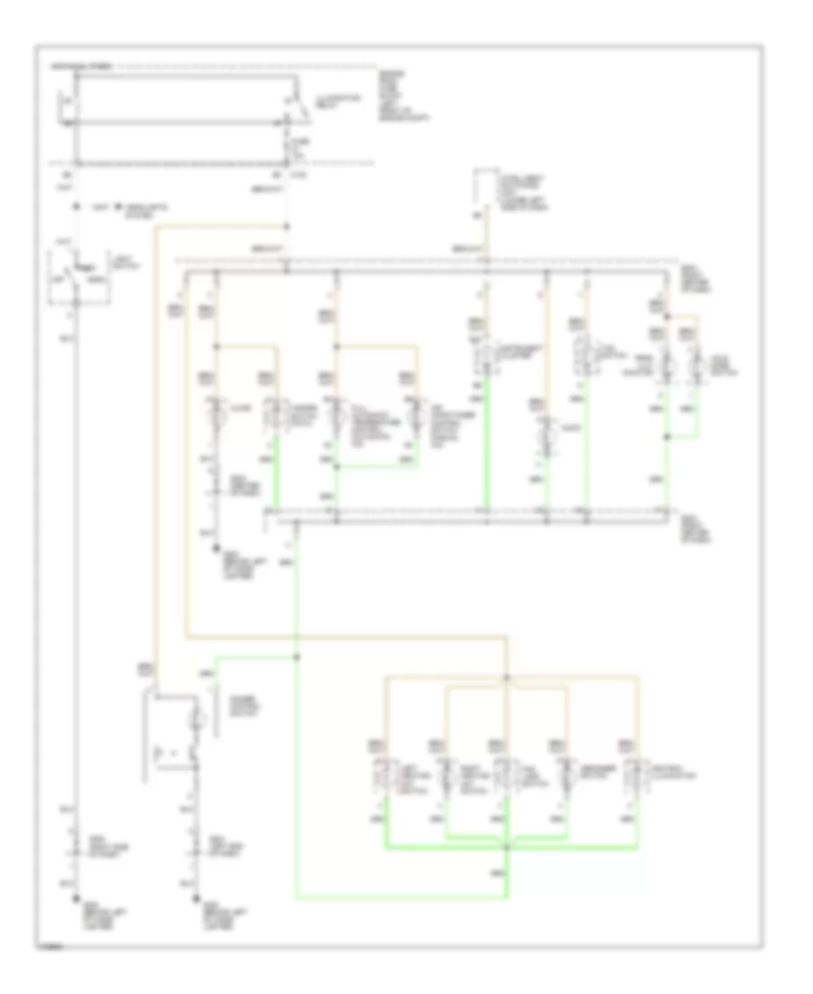
Instrument Illumination Wiring Diagram for Suzuki Verona LX 2005
List of elements for Instrument Illumination Wiring Diagram for Suzuki Verona LX 2005:
- Air conditioner control switch (manual a/c)
- Ashtray illumination
- Audio
- B10
- C102
- Clock
- Defogger switch
- Dimmer control switch
- Engine room fuse block (left front of engine compt)
- Fog lamp switch
- Full automatic temperature control (automatic a/c)
- Fuse 10a
- G202 (behind left of cigar lighter)
- Hazard switch (fatc)
- Head
- Headlights system
- Hold mode switch
- Hot at all times
- Illumination relay
- Instrument cluster
- Intelligent switching unit (lower left side of dash)
- Left heating mat switch
- Light switch
- Off
- Park
- Prnd illu- mination
- Right heating mat switch
- S201 (left end of dash)
- S202 (right side of dash)
- S203 (center of dash)
- S204 (right center of dash)
- Tcs switch
POWER DISTRIBUTION
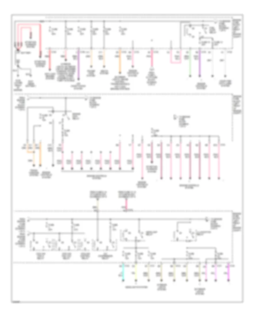
Power Distribution Wiring Diagram (1 of 3) for Suzuki Verona LX 2005
List of elements for Power Distribution Wiring Diagram (1 of 3) for Suzuki Verona LX 2005:
- A/c compressor relay
- A10
- A11
- Air conditioning system
- Anti-lock brakes system
- B11
- B12
- Battery
- C101 b1
- C101 b9
- C102
- C102 a4
- C102 b3
- C102 b6
- C102 c8
- C103
- C105
- C106
- C11
- Computer data lines system
- Cooling control relay
- Cooling fan hi relay
- Cooling fan low relay
- Engine controls system
- Engine fuse block (left front of engine compt)
- Engine main relay
- Exterior lights system
- Exterior lights, cruise control, transmissions & anti-lock brakes systems
- From engine fuse block (diagram 1 of 3)
- From fuse 12, in i/p fuse block, (diagram 3 of 3)
- From fuse 3 in i/p fuse block, (diagram 3 of 3)
- From fuse 6, in i/p fuse block, (diagram 2 of 3)
- Fuel pump relay
- Fuse 10a
- Fuse 12 20a
- Fuse 15 20a
- Fuse 15a
- Fuse 20a
- Fuse 30a
- Fuse 60a
- G106 (lower front of engine)
- G107 (near battery)
- Headlamp relay
- Headlights system
- Illumination relay
- Interior lights system
- Interior lights, exterior lights, defogger, warning, power windows, door locks, wiper/ washer & anti- theft systems
- Nca
- Pnk
- Power tops system
- Red
- Seats system
- Starting/ charging system
- To engine fuse block (diagram 1 of 3)
- To engine fuse block (diagram 2 of 3)
- Trans- missions system
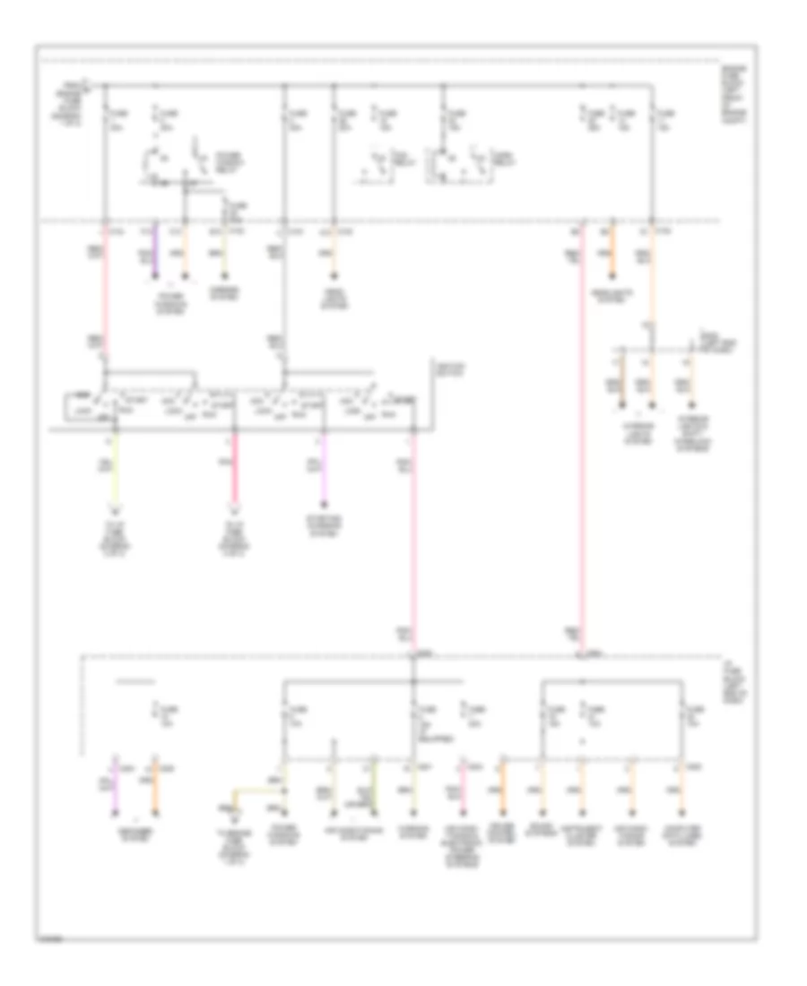
Power Distribution Wiring Diagram (2 of 3) for Suzuki Verona LX 2005
List of elements for Power Distribution Wiring Diagram (2 of 3) for Suzuki Verona LX 2005:
- Acc
- Air condi- tioning & electronic power steering systems
- Air condi- tioning system
- Air conditioning system
- C10
- C102 a10
- C102 b10
- C102 d1
- C104
- C201
- C203
- C204
- C205
- Computer data lines system
- Cruise control system
- Defogger system
- Engine fuse block (left front of engine compt)
- F10
- Fog relay
- From d engine fuse block (diagram 1 of 3)
- Fuse 10a
- Fuse 15a
- Fuse 15a (if equipped)
- Fuse 20a
- Fuse 25a
- Fuse 30a
- Head- lights system
- Headlights system
- Horn relay
- I/p fuse block (left end of dash)
- Ignition switch
- Instrument cluster system
- Interior lights & shift- interlock systems
- Interior lights system
- Lock
- Mirrors system
- Off
- Pnk
- Power window relay
- Power windows system
- Run
- S302 (left end of dash)
- Sound systems
- Start
- Starting/ charging system
- To engine fuse block (diagram 1 of 3)
- To i/p fuse block (diagram 3 of 3)
- Warning system
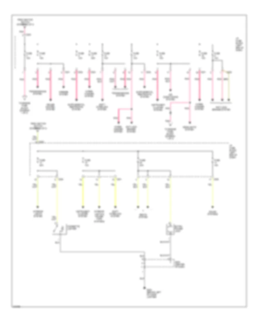
Power Distribution Wiring Diagram (3 of 3) for Suzuki Verona LX 2005
List of elements for Power Distribution Wiring Diagram (3 of 3) for Suzuki Verona LX 2005:
- Air conditioning system
- Anti-lock brakes system
- C201
- C202
- C203
- C204
- C205
- Cigarette lighter
- Cruise control system
- Extra power jack
- From ignition switch (diagram 2 of 3)
- Fuse 10a
- Fuse 15a
- Fuse 20a
- Fuse 25a
- G202 (behind left of cigar lighter)
- Headlights system
- I/p fuse block (left end of dash)
- Instrument cluster system
- Interior lights & power tops systems
- Interior lights system
- Mirrors system
- Pnk
- S203 (center of dash)
- Seats system
- Shift interlock system
- Sound systems
- To engine fuse block (diagram 1 of 3)
- Transmissions system
- Wiper/ washer system
POWER DOOR LOCKS
Power Door Locks Wiring Diagram for Suzuki Verona LX 2005
List of elements for Power Door Locks Wiring Diagram for Suzuki Verona LX 2005:
- A10
- A11
- Anti-theft system
- C106
- C201
- C202
- Engine fuse block (left front of eng compt)
- Fuse 11 10a
- Fuse 5 60a
- Fuse 6 10a
- G301 (under driver seat)
- G302 (under right front seat)
- Hot at all times
- Hot in on
- Hot in on or start
- I/p fuse block (left end of dash)
- Ign+
- Ign2
- Intelligent switching unit (lower left side of dash)
- Left central door lock unit
- Left front door actuator
- Left rear door actuator
- Lock
- Pnk
- Red
- Right central door lock unit
- Right front door actuator
- Right rear door actuator
- S302 (left end of dash)
- Unlock
POWER MIRRORS
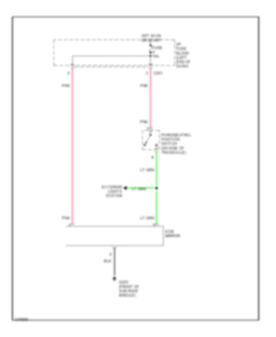
Electrochromic Mirror Wiring Diagram for Suzuki Verona LX 2005
List of elements for Electrochromic Mirror Wiring Diagram for Suzuki Verona LX 2005:
- C201
- Ecm mirror
- Exterior lights system
- Fuse 15a
- G203 (front of sun roof module)
- Hot in on or start
- I/p fuse block (left end of dash)
- Park/neutral position switch (on side of transaxle)
- Pnk
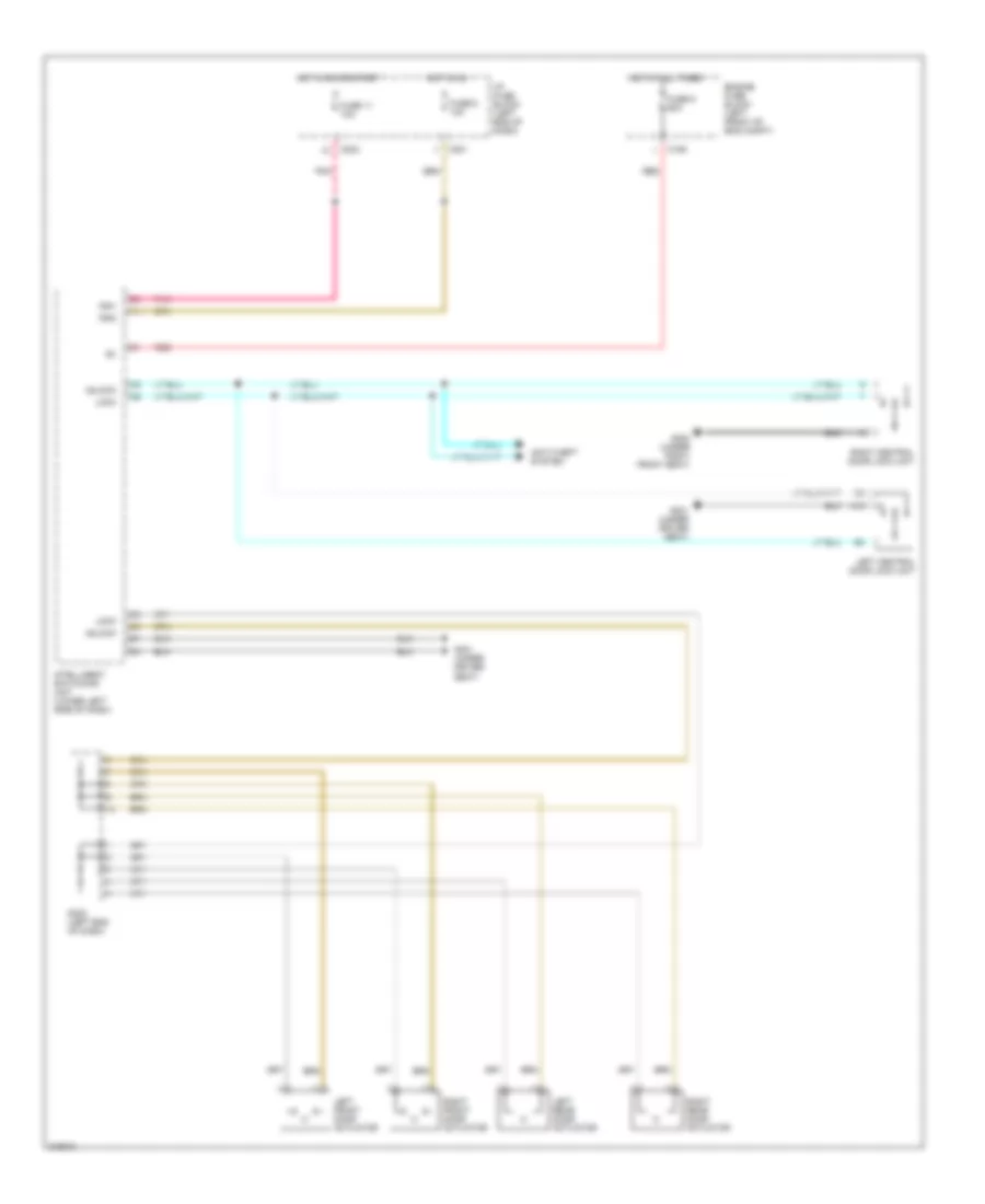
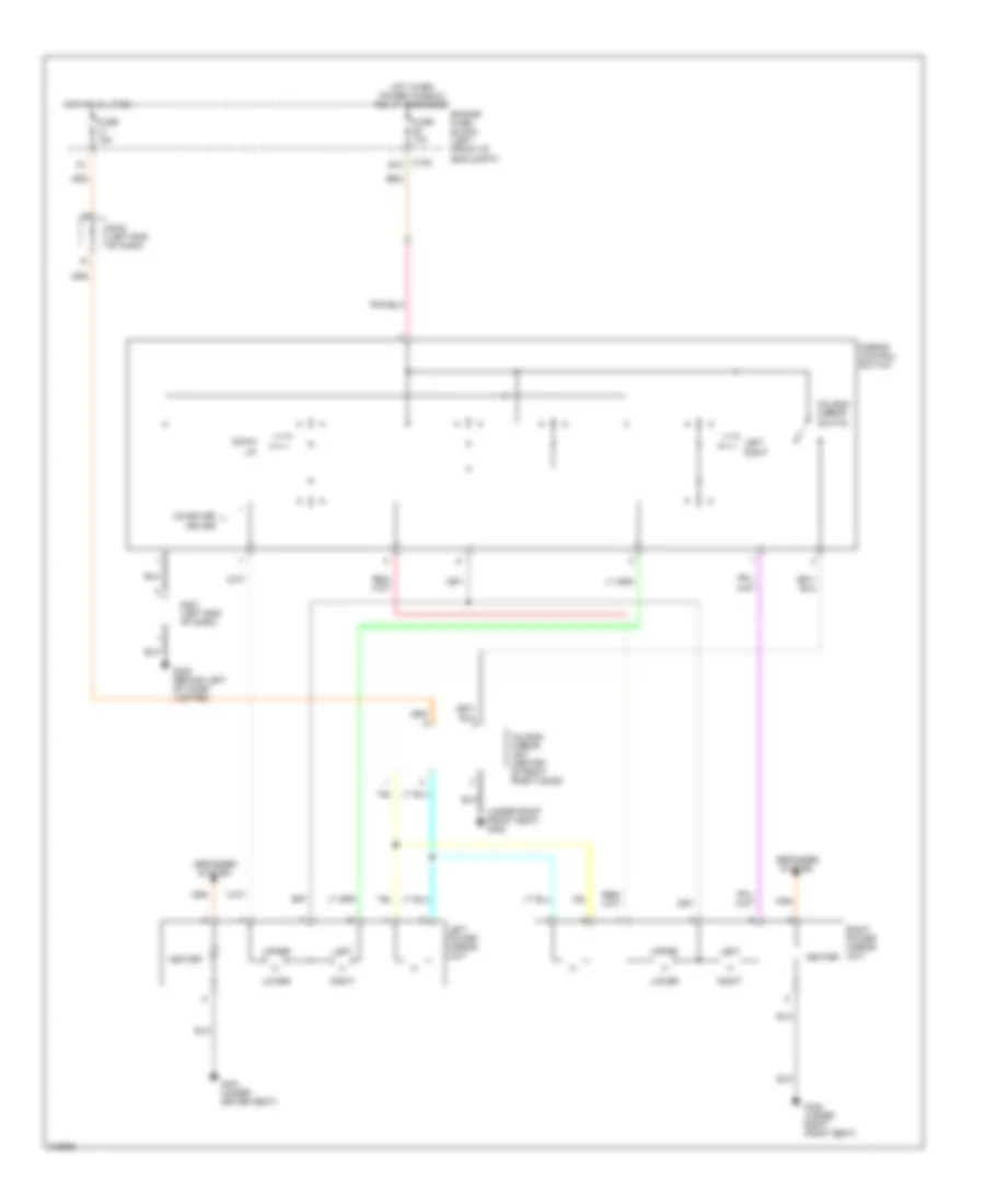
Power Mirrors Wiring Diagram for Suzuki Verona LX 2005
List of elements for Power Mirrors Wiring Diagram for Suzuki Verona LX 2005:
- (under right front seat) g302
- B10
- C102
- Co-driver
- Defogger system
- Down
- Driver
- Engine fuse block (left front of eng compt)
- Folding mirror switch
- Folding mirror unit (center of right front door)
- Fuse 10a
- Fuse 15a
- G202 (behind left of cigar lighter)
- G301 (under driver seat)
- G302 (under right front seat)
- Heater
- Hot at all time
- Hot when power window relay energized
- Left
- Left power mirror unit
- Lower
- Mirror control switch
- Right
- Right power mirror unit
- S201 (left end of dash)
- S302 (left end of dash)
- Upper
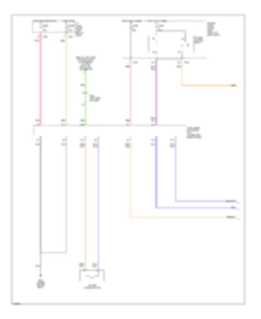
POWER SEATS
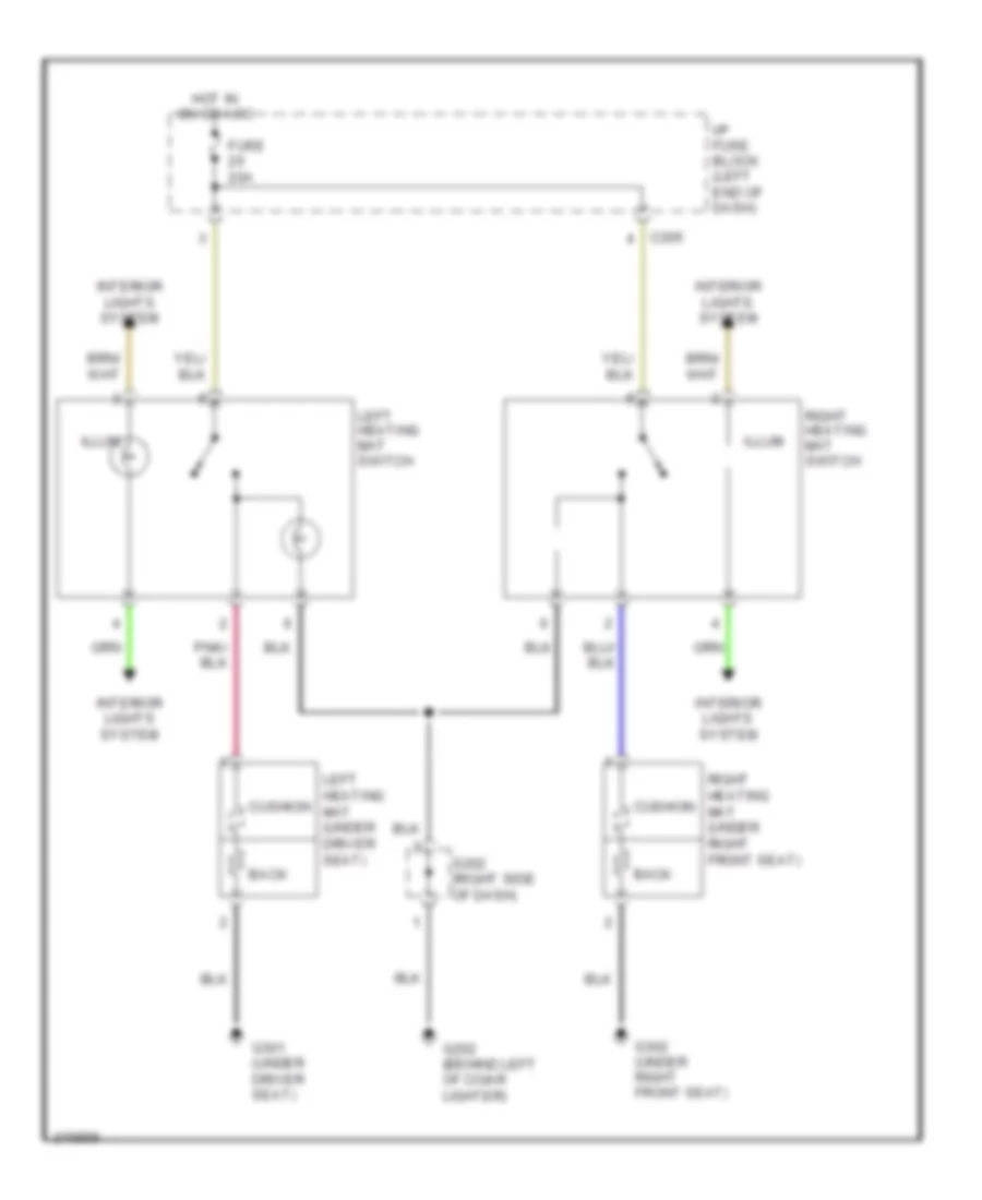
Heated Seats Wiring Diagram for Suzuki Verona LX 2005
List of elements for Heated Seats Wiring Diagram for Suzuki Verona LX 2005:
- Back
- C205
- Cushion
- Fuse 20a
- G202 (behind left of cigar lighter)
- G301 (under driver seat)
- G302 (under right front seat)
- Hot in on or acc
- I/p fuse block (left end of dash)
- Illum
- Interior lights system
- Left heating mat (under driver seat)
- Left heating mat switch
- Right heating mat (under right front seat)
- Right heating mat switch
- S202 (right side of dash)
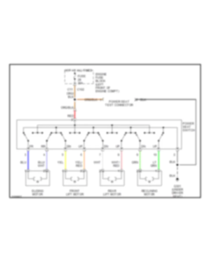
Power Seat Wiring Diagram for Suzuki Verona LX 2005
List of elements for Power Seat Wiring Diagram for Suzuki Verona LX 2005:
- C102
- C11
- Engine fuse block (left front of engine compt)
- Front lift motor
- Fuse 30a
- G301 (under driver seat)
- Hot at all times
- Power seat switch
- Power seat test connector
- Rear lift motor
- Reclining motor
- Red
- Sliding motor
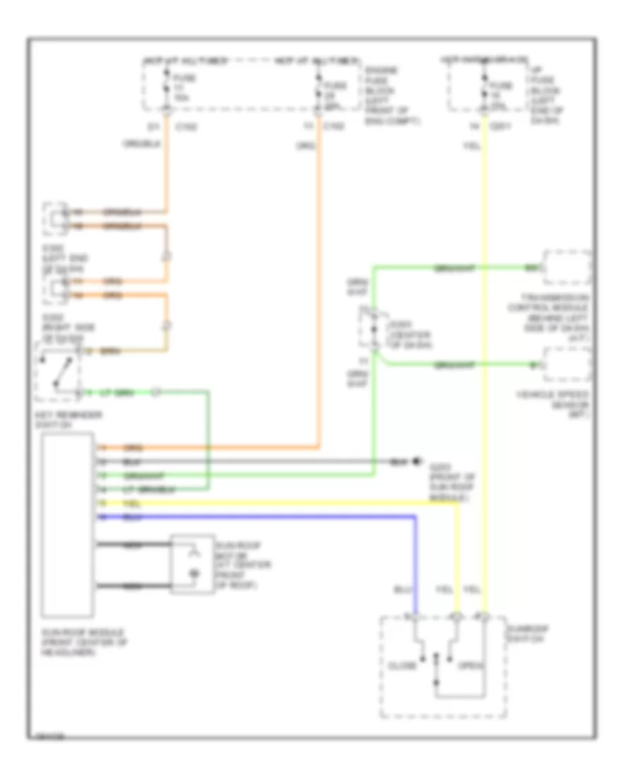
POWER TOP/SUNROOF
Power Top/Sunroof Wiring Diagram for Suzuki Verona LX 2005
List of elements for Power Top/Sunroof Wiring Diagram for Suzuki Verona LX 2005:
- C102
- C201
- Close
- Engine fuse block (left front of eng compt)
- Fuse 15a
- Fuse 20a
- G203 (front of sun roof module)
- Hot at all times
- Hot in run or acc
- I/p fuse block (left end of dash)
- Key reminder switch
- Nca
- Open
- S202 (right side of dash)
- S203 (center of dash)
- S302 (left end of dash)
- Sun roof module (front center of headliner)
- Sun roof motor (at center front of roof)
- Sunroof switch
- Transmission control module (behind left side of dash) (a/t)
- Vehicle speed sensor (m/t)
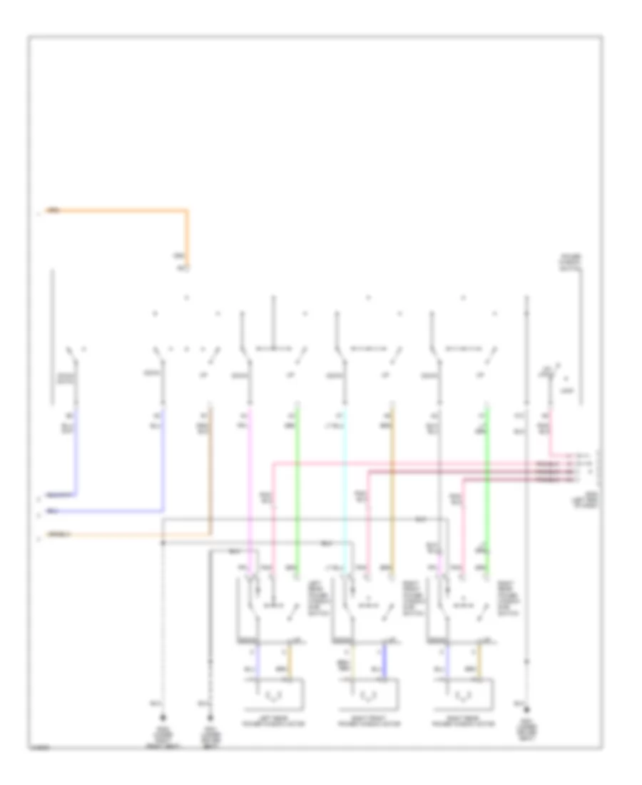
POWER WINDOWS
Power Windows Wiring Diagram (1 of 2) for Suzuki Verona LX 2005
List of elements for Power Windows Wiring Diagram (1 of 2) for Suzuki Verona LX 2005:
- (below left side of dash, right of steering column) data link connector
- A10
- A11
- A12
- A13
- B19
- C10
- C102
- C106
- C201
- C202
- Engine fuse block (left front of eng compt)
- F10
- Fuse 10a
- Fuse 20a
- Fuse 60a
- G301 (under driver seat)
- Hot at all times
- Hot in run
- Hot in run or start
- I/p fuse block (left end of dash)
- Intelligent switching unit (lower left side of dash)
- Pnk
- Power window motor
- Power window relay
- Red
- S201 (left end of dash)
Power Windows Wiring Diagram (2 of 2) for Suzuki Verona LX 2005
List of elements for Power Windows Wiring Diagram (2 of 2) for Suzuki Verona LX 2005:
- A10
- Down
- Down (auto)
- G301 (under driver seat)
- G302 (under right front seat)
- Left rear power window motor
- Left rear power window sub- switch
- Lock
- Pnk
- Power window switch
- Right front power window motor
- Right front power window sub- switch
- Right rear power window motor
- Right rear power window sub- switch
- S302 (left end of dash)
- Un- lock
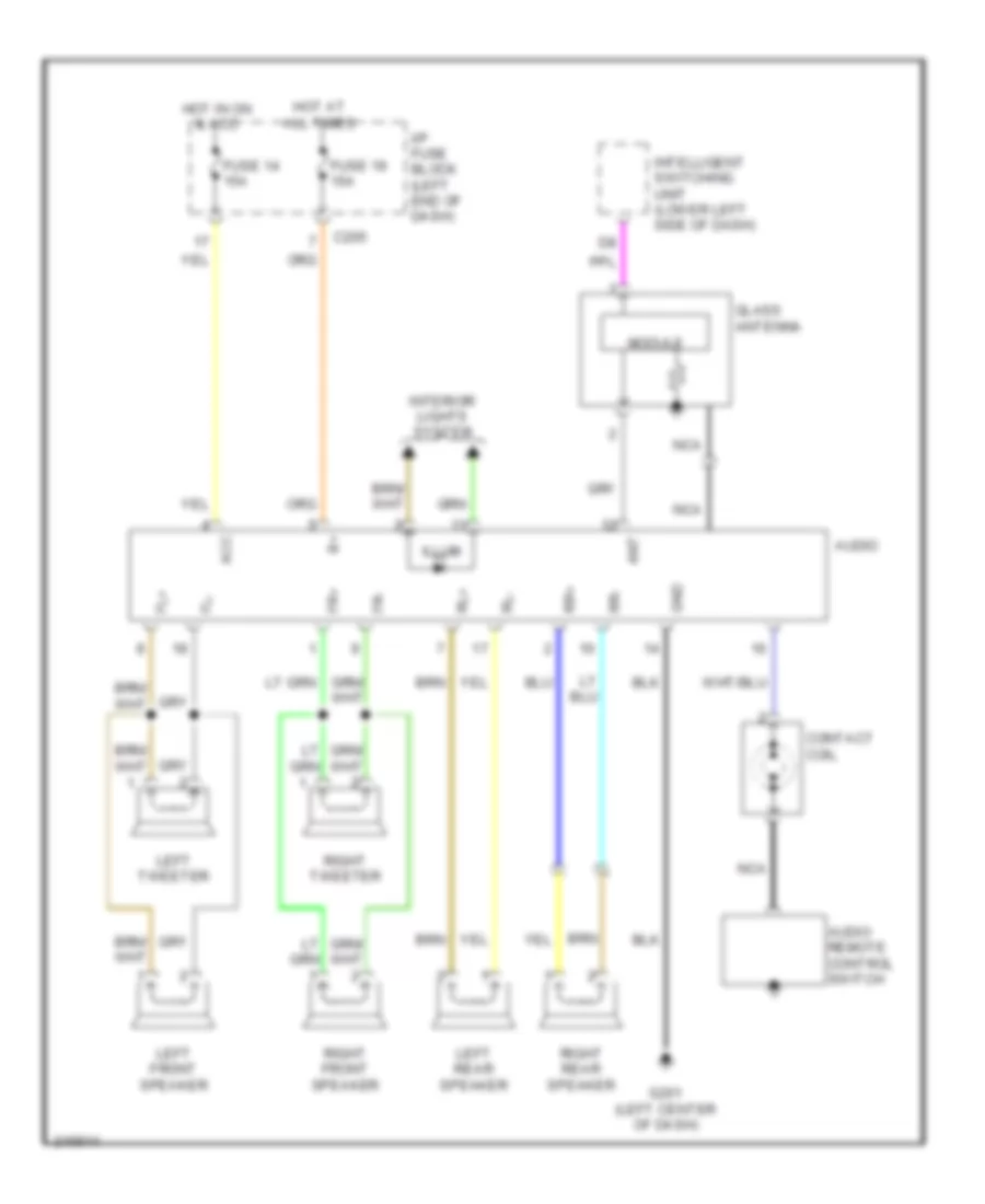
RADIO
Radio Wiring Diagram for Suzuki Verona LX 2005
List of elements for Radio Wiring Diagram for Suzuki Verona LX 2005:
- Acc
- Ant
- Audio
- Audio remote control switch
- C205
- Contact coil
- Fl+
- Fl-
- Fr+
- Fr-
- Fuse 14 15a
- Fuse 19 15a
- G201 (left center of dash)
- Glass antenna
- Gnd
- Hot at all times
- Hot in on & acc
- I/p fuse block (left end of dash)
- Illum
- Intelligent switching unit (lower left side of dash)
- Interior lights system
- Left front speaker
- Left rear speaker
- Left tweeter
- Module
- Nca
- Right front speaker
- Right rear speaker
- Right tweeter
- Rl+
- Rl-
- Rr+
- Rr-
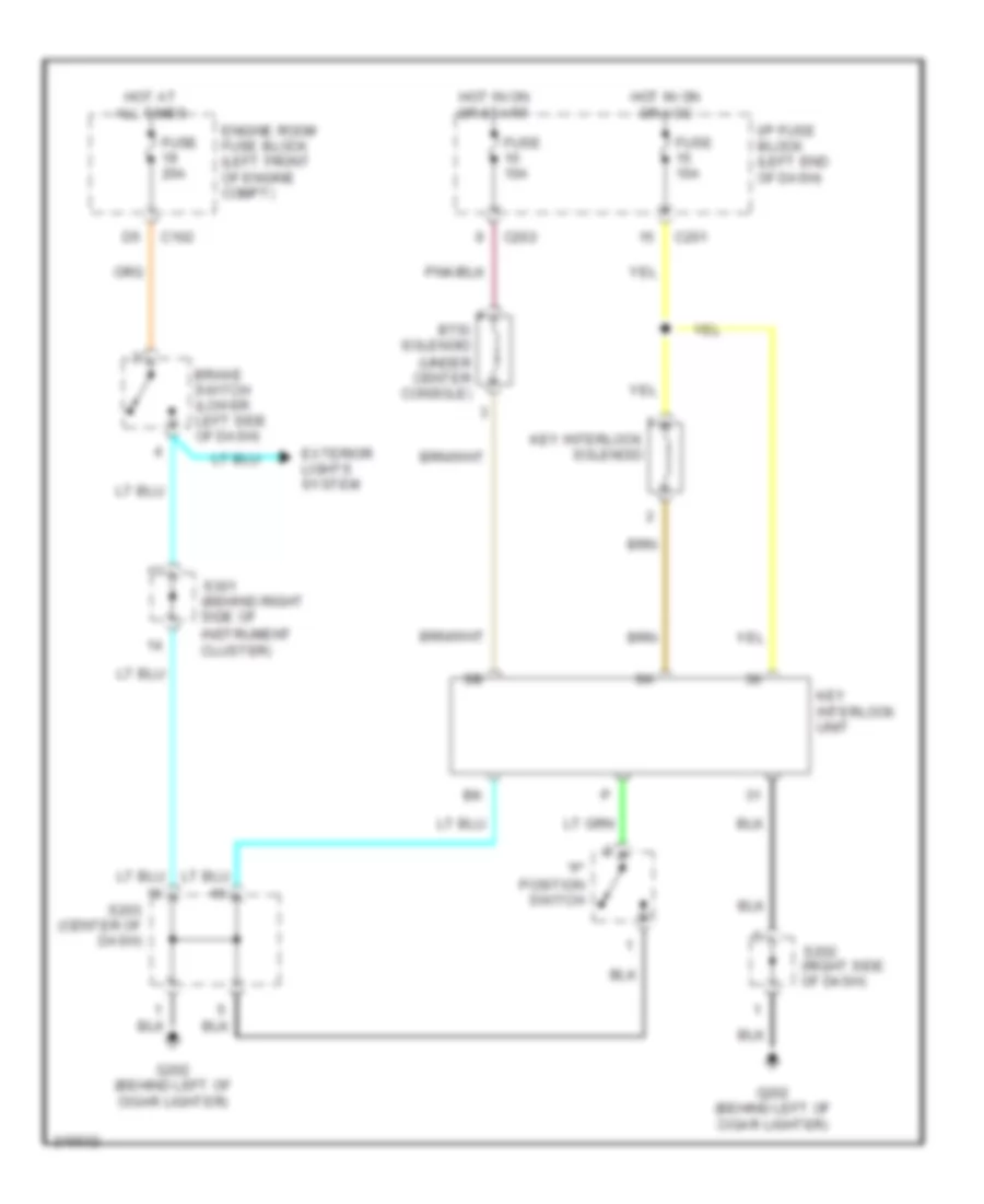
SHIFT INTERLOCK
Shift Interlock Wiring Diagram for Suzuki Verona LX 2005
List of elements for Shift Interlock Wiring Diagram for Suzuki Verona LX 2005:
- "p" position switch
- Brake switch (lower left side of dash)
- Btsi solenoid (under center console)
- C102
- C201
- C202
- Engine room fuse block (left front of engine compt)
- Exterior lights system
- Fuse 10a
- Fuse 20a
- G202 (behind left of cigar lighter)
- Hot at all times
- Hot in on or acc
- Hot in on or start
- I/p fuse block (left end of dash)
- Instrument cluster)
- Key interlock solenoid
- Key interlock unit
- S202 (right side of dash)
- S203 (center of dash)
- S301 (behind right side of
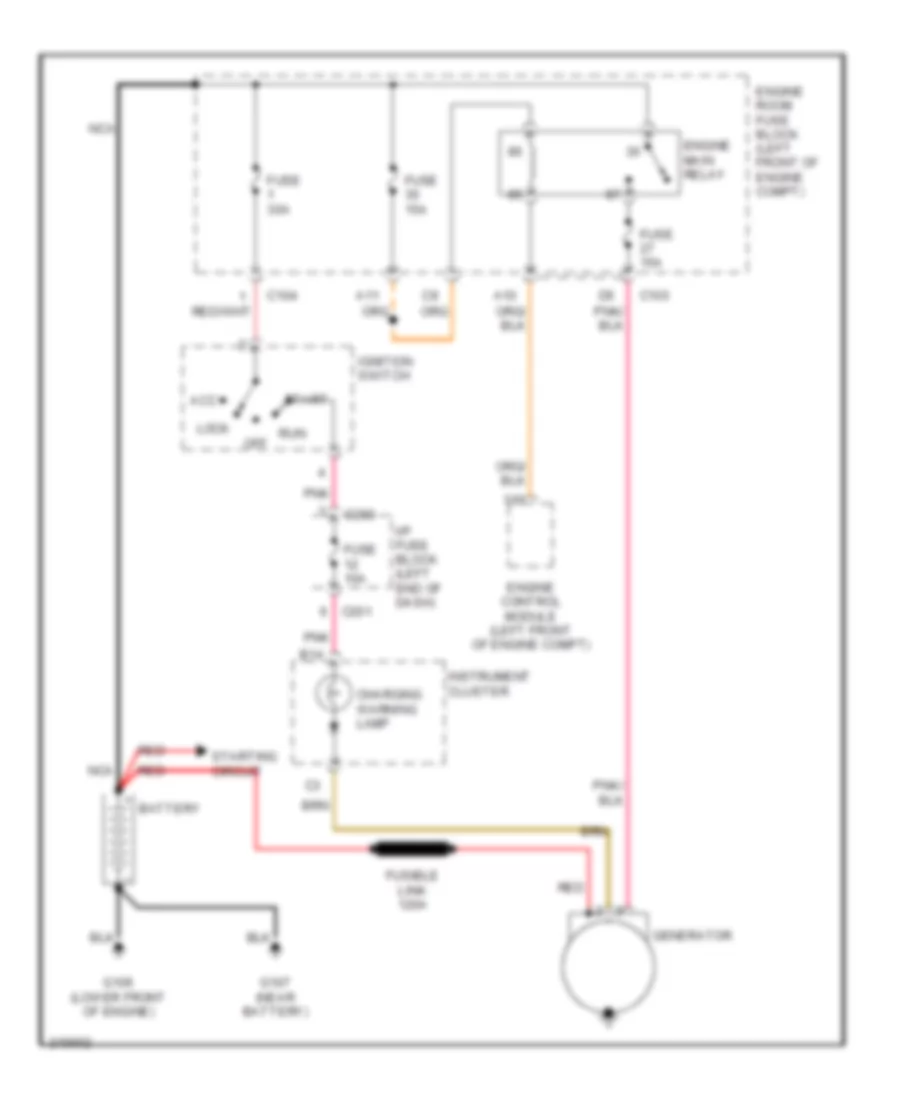
STARTING/CHARGING
Charging Wiring Diagram for Suzuki Verona LX 2005
List of elements for Charging Wiring Diagram for Suzuki Verona LX 2005:
- A10
- A11
- Acc
- B14
- Battery
- C103
- C104
- C201
- C203
- Charging warning lamp
- Engine control module (left front of engine compt)
- Engine main relay
- Engine room fuse block (left front of engine compt)
- Fuse 10a
- Fuse 15a
- Fuse 30a
- Fusible link 120a
- G106 (lower front of engine)
- G107 (near battery)
- Generator
- I/p fuse block (left end of dash)
- Ignition switch
- Instrument cluster
- Lock
- Nca
- Off
- Pnk
- Red
- Run
- Start
- Starting circuit
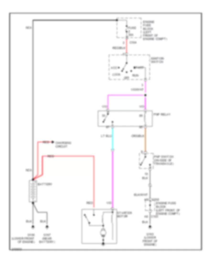
Starting Wiring Diagram for Suzuki Verona LX 2005
List of elements for Starting Wiring Diagram for Suzuki Verona LX 2005:
- A8 c103
- Acc
- Battery
- C102
- C104
- Charging circuit
- Engine fuse block (left front of engine compt)
- Fuse 30a
- G103 (lower front of engine)
- G106 (lower front of engine)
- G107 (near battery)
- Ignition switch
- Lock
- Nca
- Off
- Pnp relay
- Pnp switch (on side of transaxle)
- Red
- Run
- Start
- Starter motor
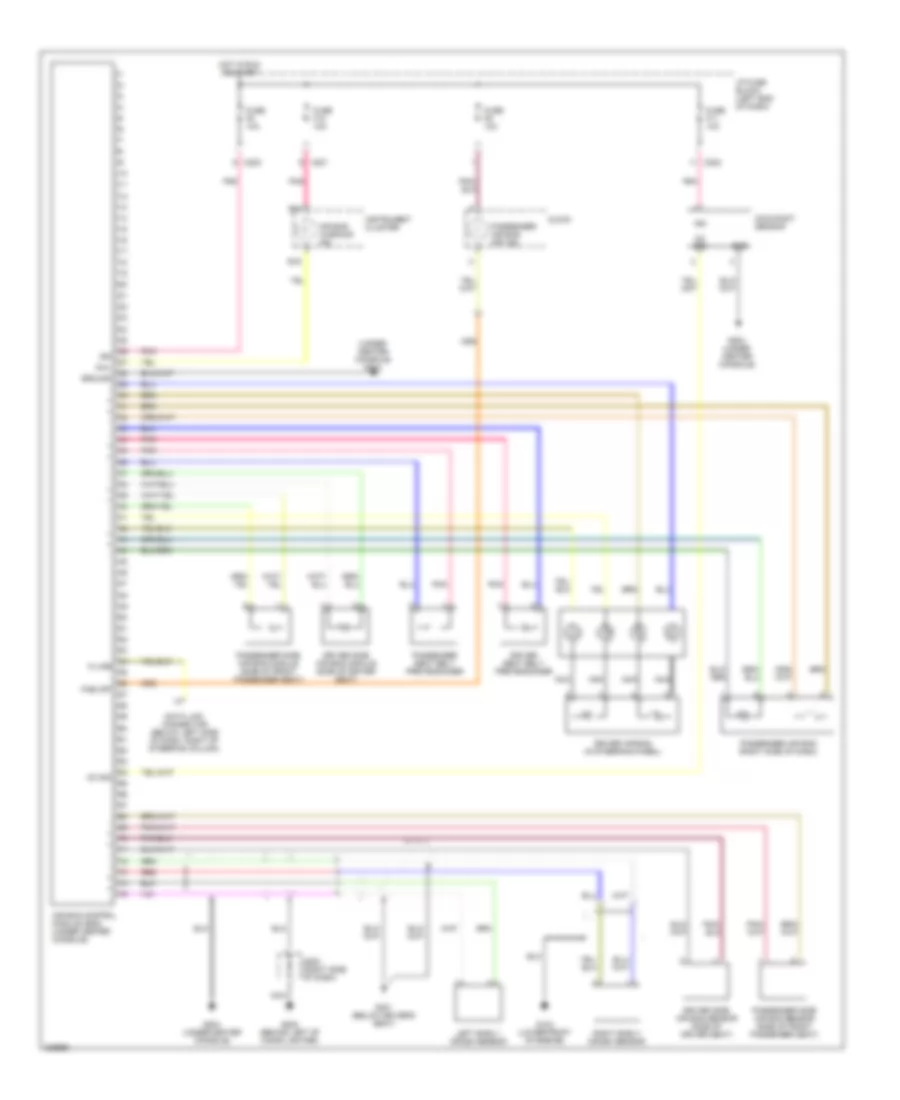
SUPPLEMENTAL RESTRAINTS
Supplemental Restraints Wiring Diagram for Suzuki Verona LX 2005
List of elements for Supplemental Restraints Wiring Diagram for Suzuki Verona LX 2005:
- (under center console) g204
- Air bag control module (sdm) (under center console)
- Air bag warning ind
- Awl
- B14
- B16
- C201
- C202
- Clock
- Data link connector (below left side of dash, right of steering column)
- Driver air bag (in steering wheel)
- Driver seat belt pretensioner
- Driver side air bag module (side of driver seat)
- Driver side air bag sensor (side of driver seat)
- Fuse f11 10a
- Fuse f12 10a
- Fuse f8 10a
- Fuse f9 10a
- G103 (lower front of engine)
- G202 (behind left of cigar lighter)
- G204 (under center console)
- G301 (below driver's seat)
- Gnd
- Ground
- Hot in run or start
- I/p fuse block (left end of dash)
- Ign
- Instrument cluster
- K-line
- Left early crash sensor
- Nca
- Oc sig
- Occupant sensor
- Pab off
- Passenger air bag (right side of dash)
- Passenger air bag off ind
- Passenger seat belt pretensioner
- Passenger side air bag module (side of front passenger seat)
- Passenger side air bag sensor (side of front passenger seat)
- Pnk
- Red
- Right early crash sensor
- S202 (right side of dash)
TRANSMISSION
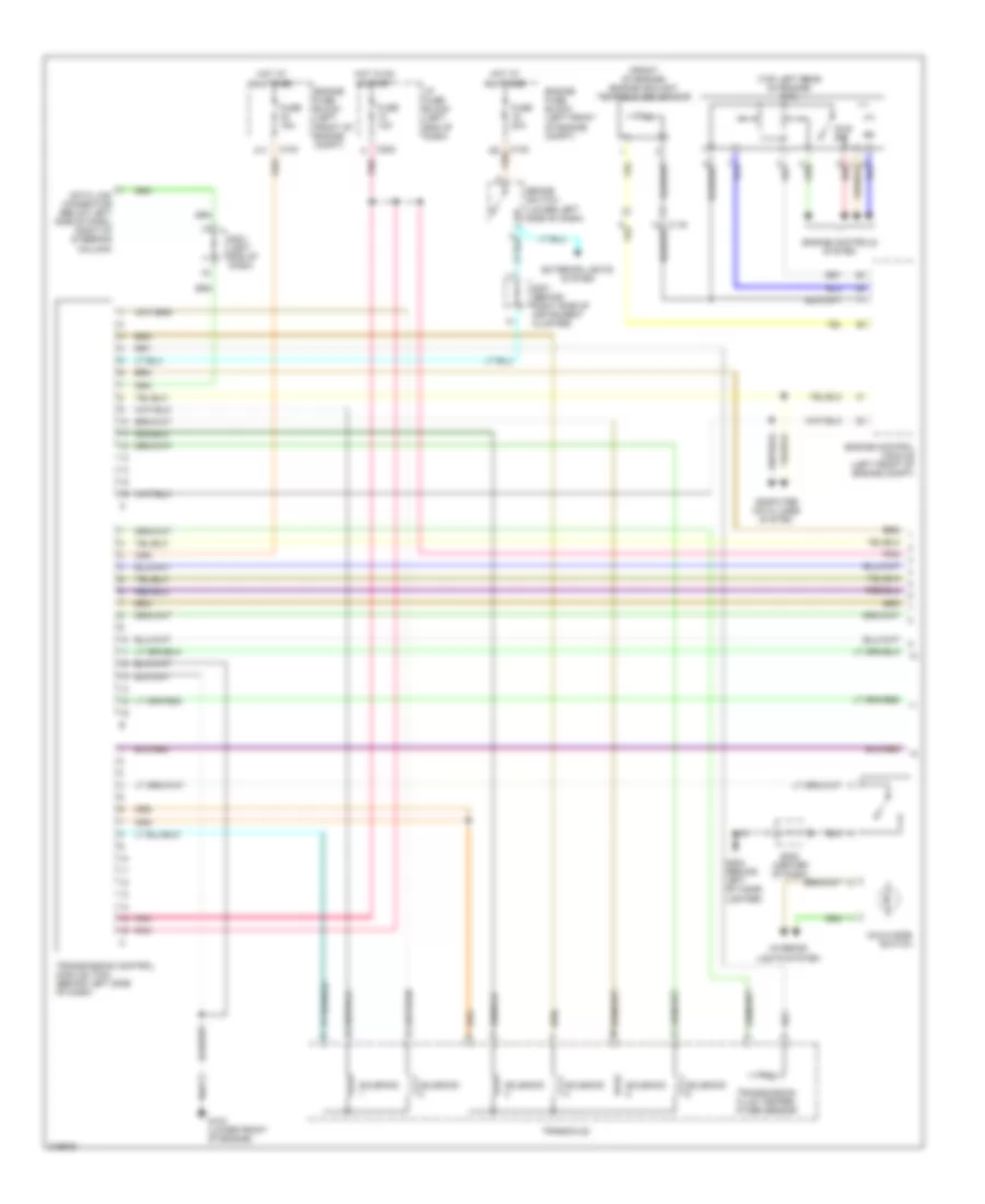
Transmission Wiring Diagram (1 of 2) for Suzuki Verona LX 2005
List of elements for Transmission Wiring Diagram (1 of 2) for Suzuki Verona LX 2005:
- (front of engine) engine coolant temperature sensor
- (top left rear of engine) mtia
- A11
- Brake switch (lower left side of dash)
- C102
- C103
- C119
- C202
- Computer data lines system
- Data link connector (below left side of dash, right of steering column)
- Engine control module (left front of engine compt)
- Engine controls system
- Engine fuse block (left front of engine compt)
- Exterior lights system
- Fuse 10a
- Fuse 15a
- Fuse 20a
- G103 (lower front of engine)
- G202 (behind left of cigar lighter)
- Hold mode switch
- Hot at all times
- Hot in on & start
- I/p fuse block (left end of dash)
- Idle sw
- Interior lights system
- Pnk
- Red
- S201 (left end of dash)
- S203 (center of dash)
- S301 (behind right side of instrument cluster)
- Solenoid
- Transaxle
- Transmission control module (tcm) (behind left side of dash)
- Transmission fluid temper- ature sensor
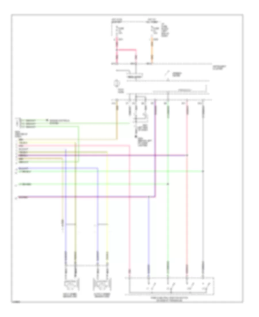
Transmission Wiring Diagram (2 of 2) for Suzuki Verona LX 2005
List of elements for Transmission Wiring Diagram (2 of 2) for Suzuki Verona LX 2005:
- A10
- B11
- B12
- B13
- B14
- C14
- C201
- C205
- Engine controls system
- Fuse 10a
- G202 (behind left of cigar lighter)
- Hold mode
- Hot at all times
- Hot in on & start
- I/p fuse block (left end of dash)
- Input speed sensor (iss)
- Instrument cluster
- Nca
- Output speed sensor (oss)
- P r n d 3 2 1
- Park & neutral position switch (on side of transaxle)
- Pnk
- Regulator
- S201 (left end of dash)
- S203 (center of dash)
- Speedo- meter
TRUNK, TAILGATE, FUEL DOOR
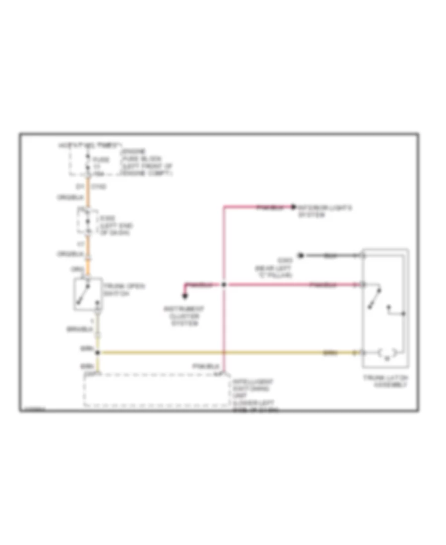
Trunk Release Wiring Diagram for Suzuki Verona LX 2005
List of elements for Trunk Release Wiring Diagram for Suzuki Verona LX 2005:
- (near left "c" pillar)
- D1 c102
- Engine fuse block (left front of engine compt)
- Fuse 15a
- G303
- Hot at all times
- Instrument cluster system
- Intelligent switching unit (lower left side of dash)
- Interior lights system
- S302 (left end of dash)
- Trunk latch assembly
- Trunk open switch
WARNING SYSTEMS
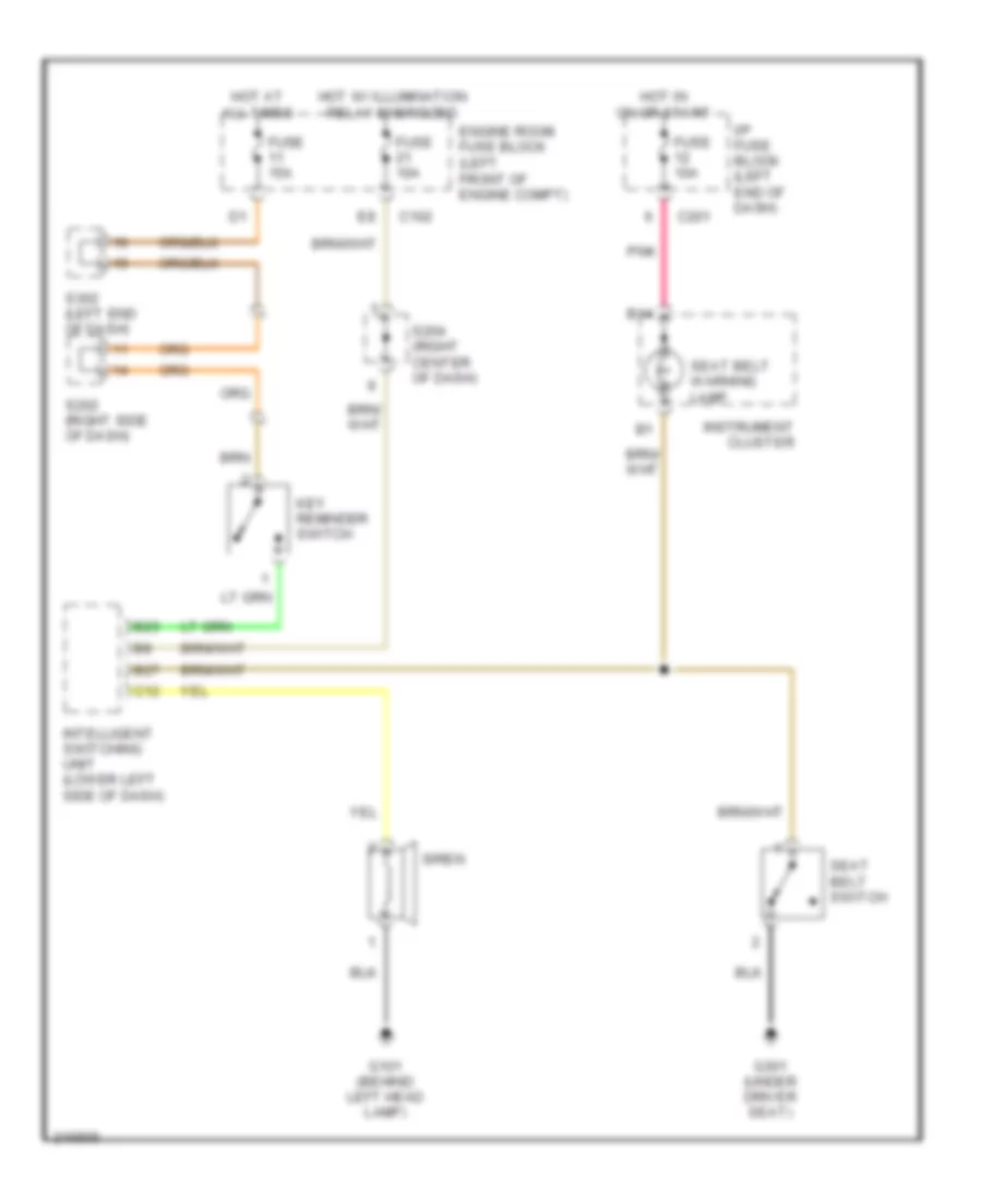
Key Reminder & Seat Belt Warning Wiring Diagram for Suzuki Verona LX 2005
List of elements for Key Reminder & Seat Belt Warning Wiring Diagram for Suzuki Verona LX 2005:
- B14
- B23
- B27
- C102
- C12
- C201
- Engine room fuse block (left front of engine compt)
- Fuse 10a
- Fuse 15a
- G101 (behind left head lamp)
- G301 (under driver seat)
- Hot at all times
- Hot in on or start
- Hot w/ illumination relay energized
- I/p fuse block (left end of dash)
- Instrument cluster
- Intelligent switching unit (lower left side of dash)
- Key reminder switch
- Pnk
- S202 (right side of dash)
- S204 (right center of dash)
- S302 (left end of dash)
- Seat belt switch
- Seat belt warning lamp
- Siren
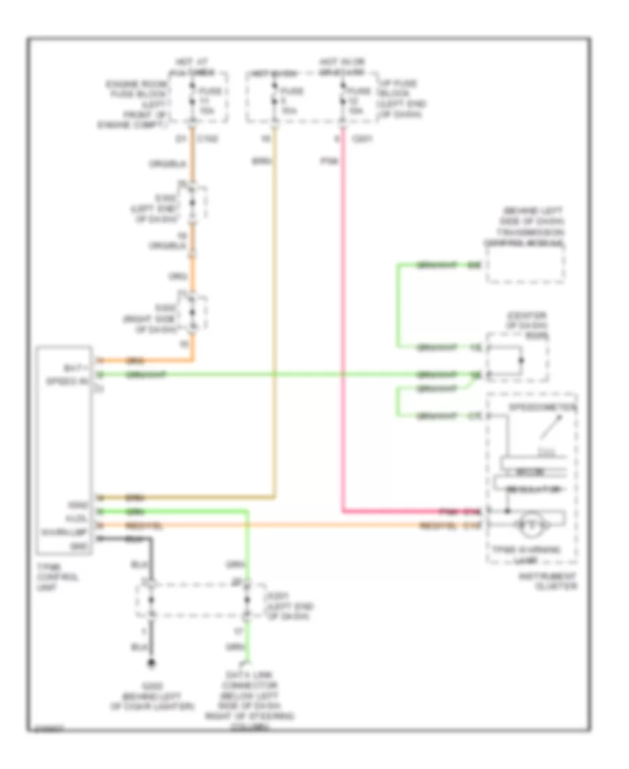
Tire Pressure Monitoring Wiring Diagram for Suzuki Verona LX 2005
List of elements for Tire Pressure Monitoring Wiring Diagram for Suzuki Verona LX 2005:
- (behind left side of dash)
- (center of dash) s203
- Aldl
- Bat+
- C13
- C14
- C201
- D1 c102
- Data link connector (below left side of dash, right of steering column)
- Engine room fuse block (left front of engine compt)
- Fuse 10a
- Fuse 15a
- G202 (behind left of cigar lighter)
- Gnd
- Hot at all times
- Hot in on
- Hot in or or start
- I/p fuse block (left end of dash)
- Ign2
- Instrument cluster
- Micom
- Pnk
- Regulator
- S201 (left end of dash)
- S202 (right side of dash)
- S302 (left end of dash)
- Speed in
- Speedometer
- Tpms control unit
- Tpms warning lamp
- Transmission control module
- Warn lmp
WIPER/WASHER
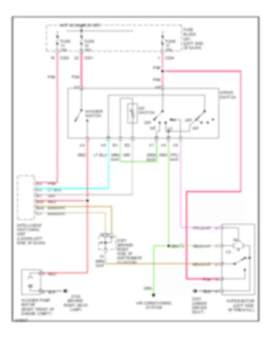
Wiper/Washer Wiring Diagram for Suzuki Verona LX 2005
List of elements for Wiper/Washer Wiring Diagram for Suzuki Verona LX 2005:
- (i/p) (left end of dash)
- Air conditioning system
- B25
- B28
- C201
- C202
- C204
- Fuse 10a
- Fuse 25a
- Fuse block
- G102 (behind right head lamp)
- G301 (under driver seat)
- Hot in on or start
- Int
- Int switch
- Intelligent switching unit (lower left side of dash)
- Off
- Pnk
- Red
- S301 (behind right side of instrument cluster)
- Washer pump motor (right front of engine compt)
- Washer switch
- Wiper motor (left side of firewall)
- Wiper switch