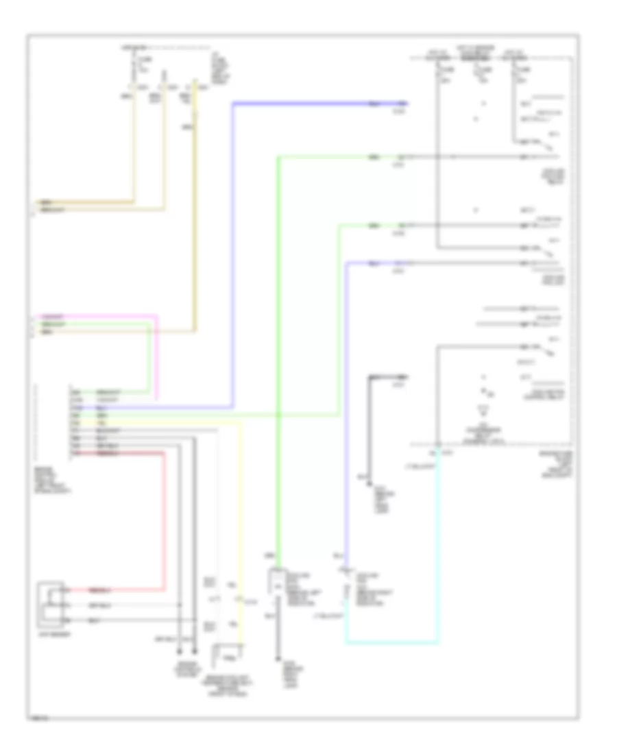
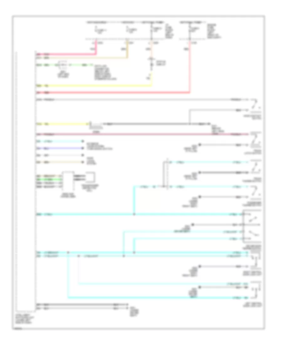
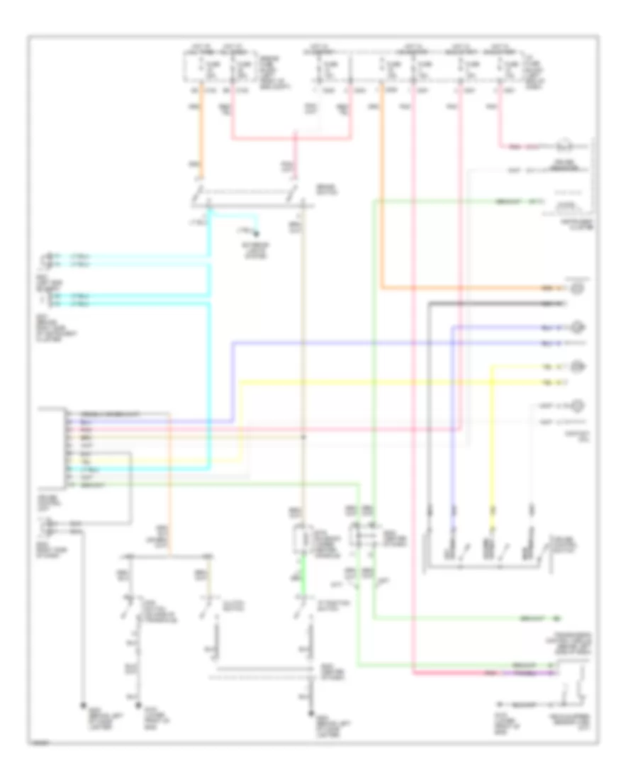
AIR CONDITIONING
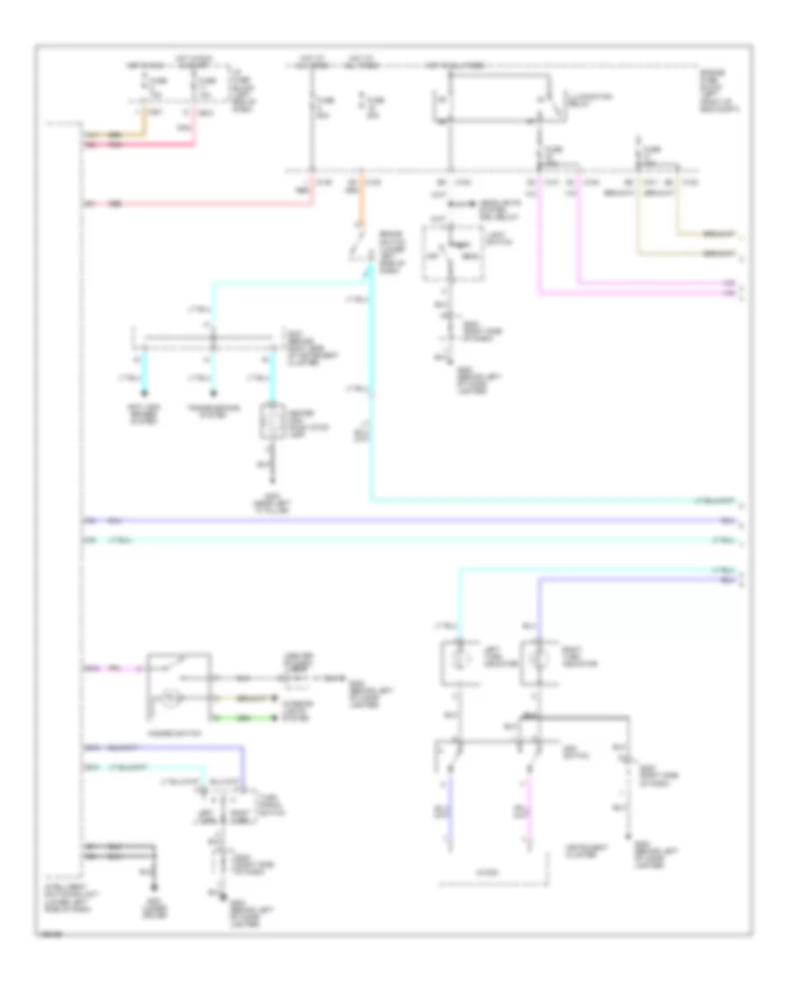
Automatic A/C Wiring Diagram (1 of 2) for Suzuki Verona S 2004

List of elements for Automatic A/C Wiring Diagram (1 of 2) for Suzuki Verona S 2004:
- A/c compressor
- A/c compressor relay
- A10
- A11
- A12
- A13
- A14
- A15
- A16
- Air mix door motor
- Ambient sensor (behind center of front bumper)
- Automatic temperature control
- B10
- B11
- B12
- B13
- B14
- B15
- B16
- B17
- B18
- B19
- B20
- Blower motor
- Blower relay
- C101
- C102
- C103
- C105
- C106
- C201
- Cooling fan control relay (diagram 2 of 2)
- Engine controls system (speed signal)
- Engine fuse block (left front of eng compt)
- Fuse 10a
- Fuse 60a
- G102 (behind right head lamp)
- G202 (behind left of cigar lighter)
- G205 (behind ashtray)
- Hot at all times
- Hot in start & on
- I/p fuse block (left end of dash)
- In-car sensor
- Intake motor
- Interior lights system
- Max high relay
- Mode motor
- Pnk
- Power transistor
- S201 (left end of dash)
- Sun sensor
- Water sensor
- Wiper/washer system
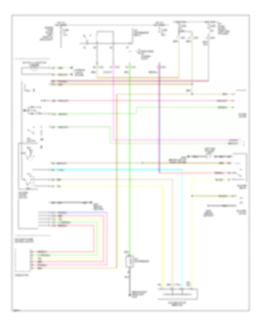
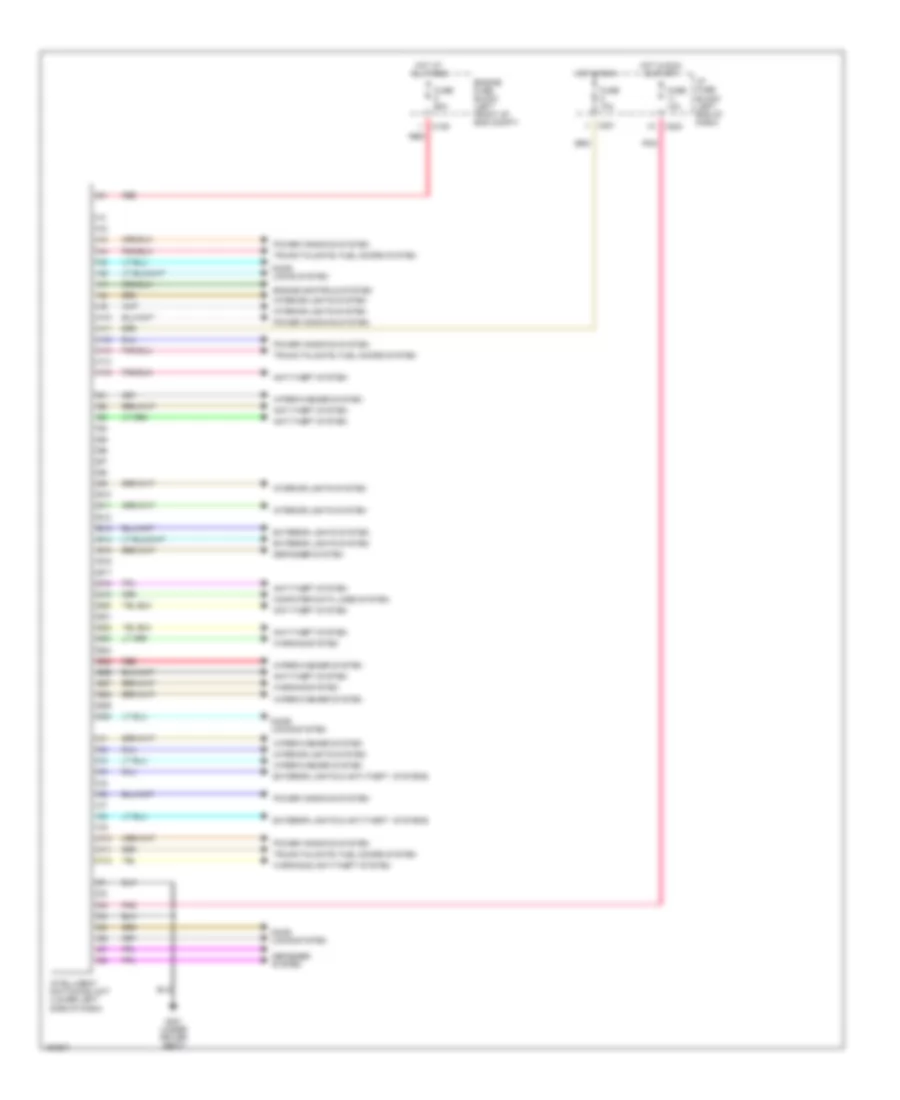
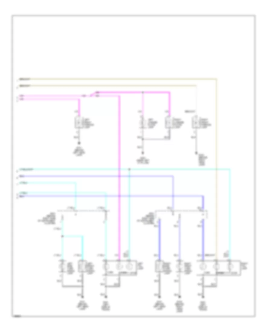
Automatic A/C Wiring Diagram (2 of 2) for Suzuki Verona S 2004
List of elements for Automatic A/C Wiring Diagram (2 of 2) for Suzuki Verona S 2004:
- 87a
- A/c compressor relay (diagram 1 of 2)
- Acp sensor
- C101
- C103
- C119
- C201
- Cooling fan aux. (behind right side of radiator)
- Cooling fan control relay
- Cooling fan high relay
- Cooling fan low
- Cooling fan main (behind left side of radiator)
- Engine control module (left front of eng compt)
- Engine controls system
- Engine coolant temperature (ect) sensor (front of eng)
- Engine fuse block (left front of eng compt)
- F11
- Fuse 10a
- Fuse 15a
- Fuse 20a
- G101 (behind left head lamp)
- G102 (behind right head lamp)
- Hot at all times
- Hot in on
- Hot w/ engine main relay energized
- I/p fuse block (left end of dash)
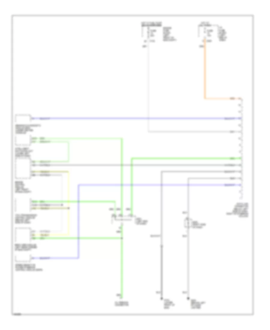
Manual A/C Wiring Diagram (1 of 2) for Suzuki Verona S 2004
List of elements for Manual A/C Wiring Diagram (1 of 2) for Suzuki Verona S 2004:
- (behind right headlamp) g102
- (left end of dash) s201
- A/c compressor
- A/c compressor relay
- A/c switch
- A11
- A12
- A13
- A14
- A15
- A17
- A19
- A20
- Air conditioner control switch
- Blower motor
- Blower motor resistor
- Blower motor switch
- Blower relay
- C101
- C102
- C103
- C106
- C201
- C204
- Engine fuse block (left front of eng compt)
- From diode d9 (diagram 2 of 2)
- Fuse 10a
- Fuse 20a
- Fuse 60a
- G202 (behind left of cigar lighter)
- G203 (behind ashtray)
- G205 (behind ashtray)
- Hot at all times
- Hot in on
- I/p fuse block (left end of dash)
- Intake motor
- Interior lights system
- Mode motor
- Off
- Red
- Switch illumination (2 bulbs)
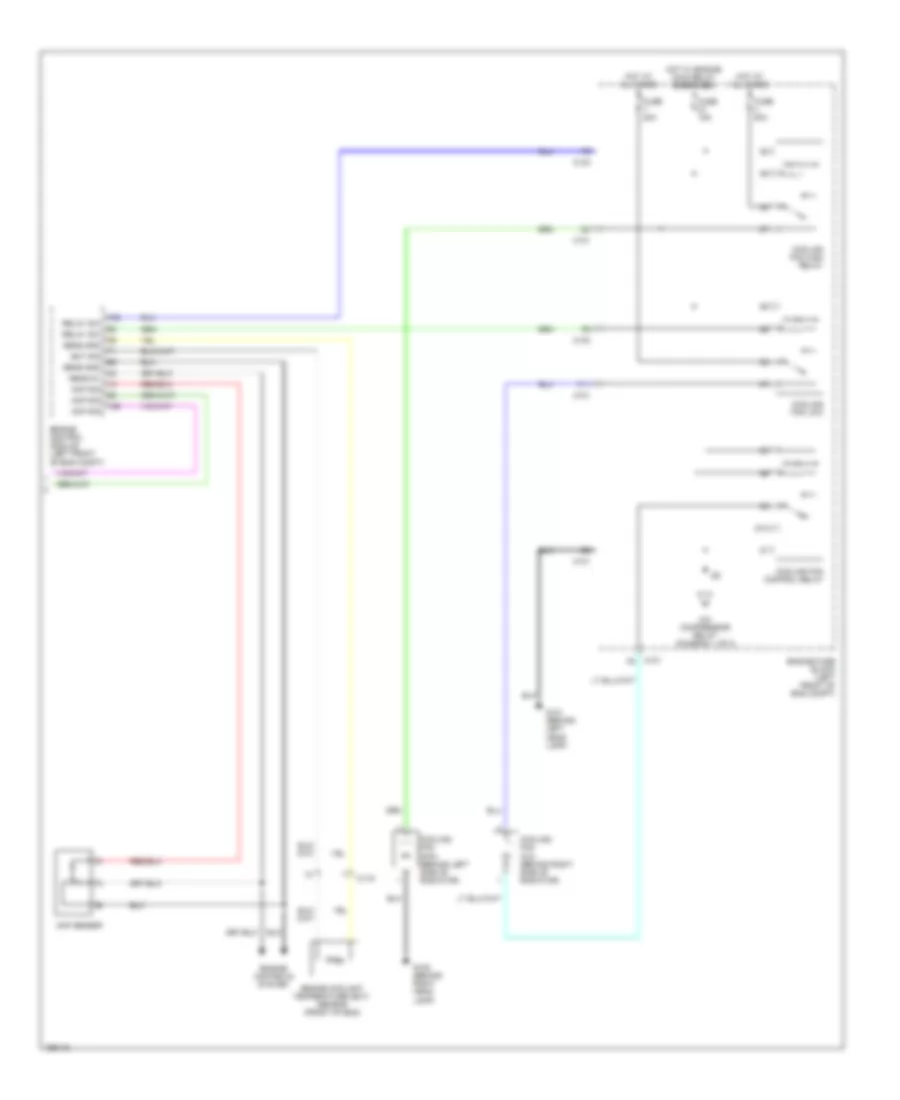
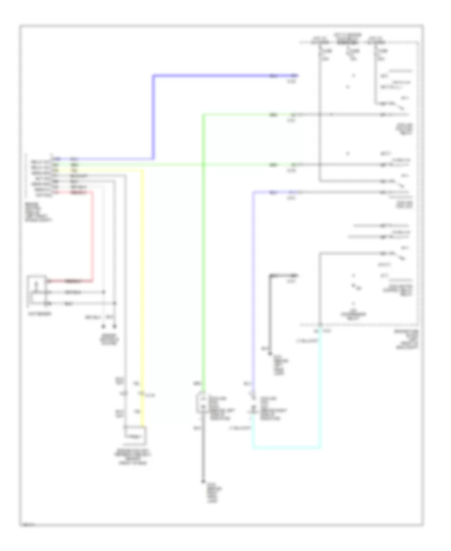
Manual A/C Wiring Diagram (2 of 2) for Suzuki Verona S 2004
List of elements for Manual A/C Wiring Diagram (2 of 2) for Suzuki Verona S 2004:
- 87a
- A/c compressor relay (diagram 1 of 2)
- Acp sensor
- Acp sig
- C101
- C103
- C119
- Cooling fan aux. (behind right side of radiator)
- Cooling fan control relay
- Cooling fan high relay
- Cooling fan low
- Cooling fan main (behind left side of radiator)
- Ect sig
- Engine control module (left front of eng compt)
- Engine controls system
- Engine coolant temperature (ect) sensor (front of eng)
- Engine fuse block (left front of eng compt)
- F11
- Fuse 15a
- Fuse 20a
- G101 (behind left head lamp)
- G102 (behind right head lamp)
- Hot at all times
- Hot w/ engine main relay energized
- Relay sw
- Sens 5v
- Sens gnd
ANTI-LOCK BRAKES
Anti-lock Brakes Wiring Diagram for Suzuki Verona S 2004
List of elements for Anti-lock Brakes Wiring Diagram for Suzuki Verona S 2004:
- (behind left of cigar lighter) g202
- A10
- A11
- A13
- A14
- A16
- Abs warning ind
- Abs warning lamp module
- B10
- B11
- Brake fluid switch
- Brake switch
- C10
- C102
- C11
- C201
- C202
- Computer data lines system
- Data link connector (below left side of dash, right of steering column)
- Ebcm (abs module) (left rear corner of eng compt)
- Engine fuse block (left front of eng compt)
- Exterior lamps system
- Fuse 10a
- Fuse 15a
- Fuse 20a
- Fuse 60a
- G105 (below ebcm)
- G202 (behind left of cigar lighter)
- Hot at all times
- Hot in run & start
- I/p fuse block (left end of dash)
- Instrument cluster
- Interior lights system
- Left front wheel speed sensor (at left front wheel hub assy)
- Left rear wheel speed sensor (at left rear wheel hub assy)
- Oil feeding connector
- Parking brake ind
- Parking brake switch
- Pnk
- Pnk b14
- Red
- Right front wheel speed sensor (at right front wheel hub assy)
- Right rear wheel speed sensor (at right rear wheel hub assy)
- S201 (left end of dash)
- S203 (center of dash)
- S301 (behind right side of instrument cluster)
- Tcs active ind
- Tcs switch
- Tcs warning ind
ANTI-THEFT
Anti-theft Wiring Diagram for Suzuki Verona S 2004
List of elements for Anti-theft Wiring Diagram for Suzuki Verona S 2004:
- A10
- A11
- A15
- B19
- B20
- B22
- B26
- B30
- C106
- C12
- C201
- C202
- C205
- Data link connector (below left side of dash, right side of steering column)
- Door locks system
- Driver door temper switch
- Engine fuse block (left front of eng compt)
- Exterior lamps system (turn signal switch)
- Fuse 11 10a
- Fuse 21 10a
- Fuse 5 60a
- Fuse 6 10a
- G101 (behind left head lamp)
- G301 (under driver seat)
- G302 (under right front seat)
- G303 (near left "c" pillar)
- Head amp (immobilizer)
- Hood contact switch
- Hot at all times
- Hot in on
- Hot in on & run
- I/p fuse block (left end of dash)
- Intelligent switching unit (lower left side of dash)
- Left central door lock unit
- Nca
- Passenger tamper switch
- Pnk
- Red
- Right central door lock unit
- S201 (left end of dash)
- Siren
- Status display
- Transponder (detection coil)
- Trunk latch switch
- Trunk tamper switch
BODY CONTROL MODULES
Body Control Modules Wiring Diagram for Suzuki Verona S 2004
List of elements for Body Control Modules Wiring Diagram for Suzuki Verona S 2004:
- A10
- A11
- A12
- A13
- A14
- A15
- Anti-theft system
- B10
- B11
- B12
- B13
- B14
- B15
- B16
- B17
- B18
- B19
- B20
- B21
- B22
- B23
- B24
- B25
- B26
- B27
- B28
- B29
- B30
- C10
- C106
- C11
- C12
- C201
- C202
- Computer data lines system
- Defogger system
- Door locks system
- Engine controls system
- Engine fuse block (left front of eng compt)
- Exterior lights & anti-theft systems
- Exterior lights system
- Fuse 10a
- Fuse 60a
- G301 (under driver seat)
- Hot at all times
- Hot in run
- Hot in run & start
- I/p fuse block (left end of dash)
- Intelligent switching unit (lower left side of dash)
- Interior lights system
- Pnk
- Power windows system
- Red
- Trunk,tailgate, fuel doors system
- Warning & anti-theft system
- Warning system
- Wiper/washer system
COMPUTER DATA LINES
Computer Data Lines Wiring Diagram for Suzuki Verona S 2004
List of elements for Computer Data Lines Wiring Diagram for Suzuki Verona S 2004:
- A16
- B19
- C102 b1
- C205
- Data link connector (below left side of dash. right of steering column)
- Ebcm (abs module) (left rear corner of eng compt)
- Engine control module (left front of eng compt)
- Engine fuse block (left front of eng compt)
- Fuse 10a
- Fuse 20a
- G103 (lower front of eng)
- G202 (behind left of cigar lighter)
- Hot at all times
- Hot w/ fuel pump relay energized
- I/p fuse block (left end of dash)
- Intelligent switching unit (lower left side of dash)
- Oil feeding connector
- S201 (left end of dash)
- S202 (right side of dash)
- Sensing & diagnostic module (sdm) (under center console)
- Speed sensitive power steering control module (ssps)
- Tcm (transmission control module) (behind left side of dash)
COOLING FAN
Cooling Fan Wiring Diagram for Suzuki Verona S 2004
List of elements for Cooling Fan Wiring Diagram for Suzuki Verona S 2004:
- 87a
- A/c compressor relay
- Acp sensor
- Acp sig
- C101
- C103
- C119
- Cooling fan aux. (behind right side of radiator)
- Cooling fan control relay relay
- Cooling fan high relay
- Cooling fan low
- Cooling fan main (behind left side of radiator)
- Ect sig
- Engine control module (left front of eng compt)
- Engine controls system
- Engine coolant temperature (ect) sensor (front of eng)
- Engine fuse block (left front of eng compt)
- F11
- Fuse 15a
- Fuse 20a
- G101 (behind left head lamp)
- G102 (behind right head lamp)
- Hot at all times
- Hot w/ engine main relay energized
- Relay sw
- Sens 5v
- Sens gnd
CRUISE CONTROL
Cruise Control Wiring Diagram for Suzuki Verona S 2004
List of elements for Cruise Control Wiring Diagram for Suzuki Verona S 2004:
- "p" position switch
- (m/t)
- A/t
- Brake switch
- Btsi solenoid (under center console)
- C102
- C11
- C14
- C201
- C202
- C204
- C205
- Clutch switch
- Contact coil
- Cruise control switch
- Cruise control unit
- Cruise indicator
- Engine fuse block (left front of eng compt)
- Exterior lights system
- Fuse 10a
- Fuse 15a
- Fuse 20a
- Fuse 25a
- G103 (lower front of eng)
- G202 (behind left of cigar lighter)
- Hot at all times
- Hot in on & start
- I/p fuse block (left end of dash)
- Instrument cluster
- M/t
- Main switch
- Mi-com
- Nca
- Pnk
- Pnp switch (on side of transaxle)
- Resume switch
- S201 (left end of dash)
- S202 (center of dash)
- S202 (right side of dash)
- S203 (center of dash)
- S301 (behind right side of instrument cluster)
- Switch set
- Transmission control module (behind left side of dash)
- Vehicle speed sensor (vss) (m/t)
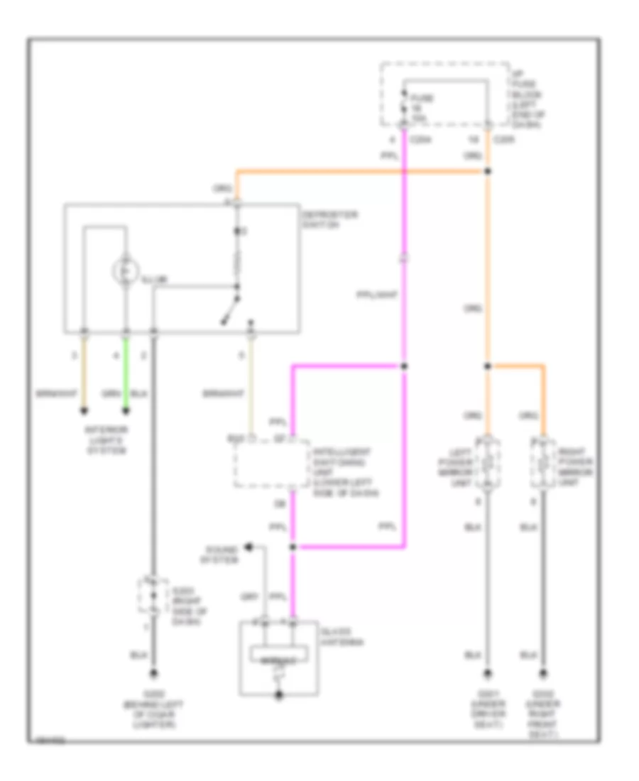
DEFOGGERS
Defoggers Wiring Diagram for Suzuki Verona S 2004
List of elements for Defoggers Wiring Diagram for Suzuki Verona S 2004:
- B15
- C204
- C205
- Defroster switch
- Fuse 10a
- G202 (behind left of cigar lighter)
- G301 (under driver seat)
- G302 (under right front seat)
- Glass antenna
- I/p fuse block (left end of dash)
- Illum
- Intelligent switching unit (lower left side of dash)
- Interior lights system
- Left power mirror unit
- Module
- Right power mirror unit
- S203 (right side of dash)
- Sound system
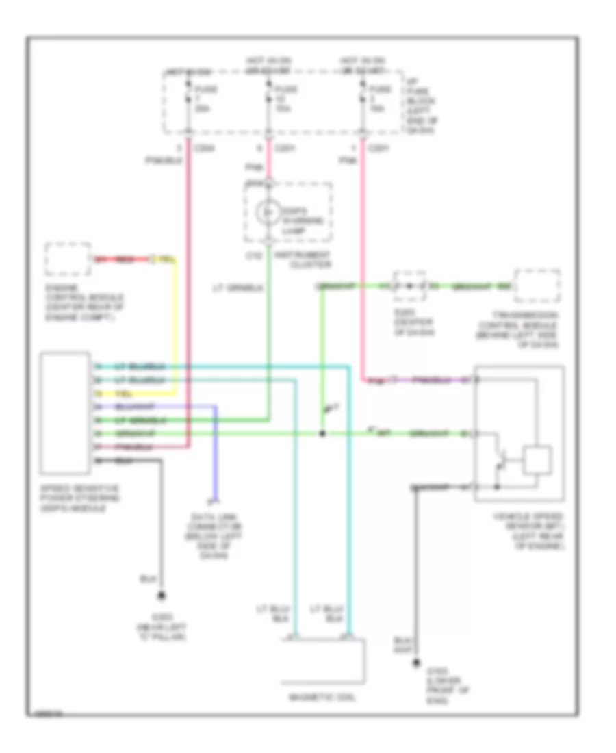
ELECTRONIC POWER STEERING
Electronic Power Steering Wiring Diagram for Suzuki Verona S 2004
List of elements for Electronic Power Steering Wiring Diagram for Suzuki Verona S 2004:
- A/t
- C12
- C14
- C201
- C204
- Data link connector (below left side of dash)
- Engine control module (center rear of engine compt)
- Fuse 10a
- Fuse 20a
- G103 (lower front of eng)
- G303 (near left "c" pillar)
- Hot in on
- Hot in on or start
- I/p fuse block (left end of dash)
- Instrument cluster
- M/t
- Magnetic coil
- Pnk
- Red
- S203 (center of dash)
- Speed sensitive power steering (ssps) module
- Ssps warning lamp
- Transmission control module (behind left side of dash)
- Vehicle speed sensor (m/t) (left rear of engine)
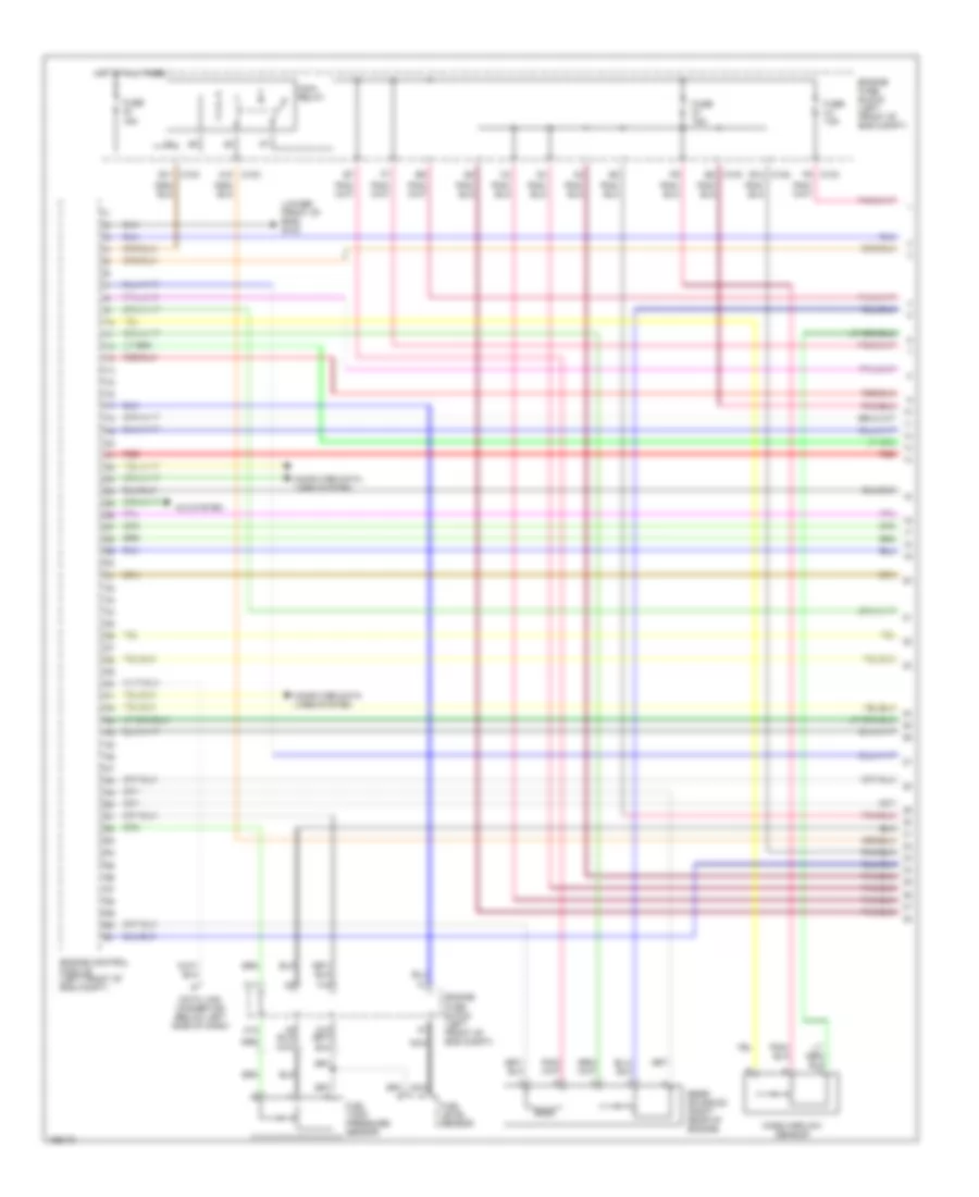
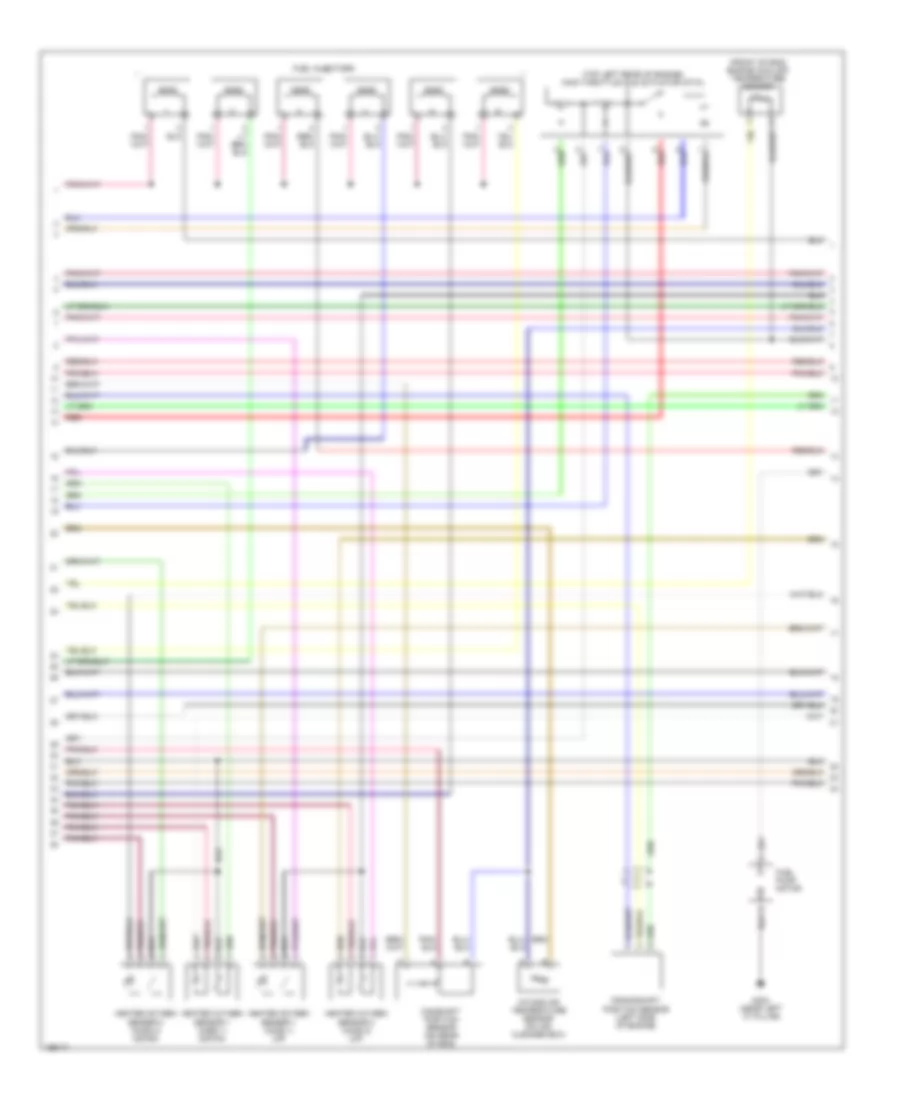
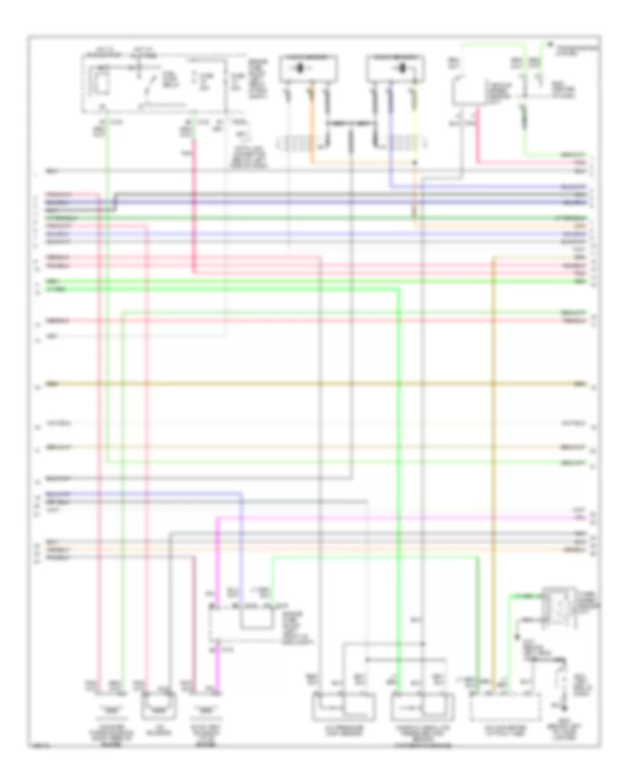
ENGINE PERFORMANCE
2.5L
2.5L, Engine Performance Wiring Diagram (1 of 4) for Suzuki Verona S 2004
List of elements for 2.5L, Engine Performance Wiring Diagram (1 of 4) for Suzuki Verona S 2004:
- (lower front of eng) g103
- A/c system
- A10 c103
- B12 c102
- B2 c103
- C103 b11
- C103 f9
- C12
- Computer data lines system
- Data link connector (below left side of dash)
- Eegr solenoid (right rear of engine)
- Engine control module (left front of eng compt)
- Engine fuse block (left front of eng compt)
- F10
- F11
- Fuel level sensor
- Fuel tank pressure sensor
- Fuse 15a
- Hot at all times
- Main relay
- Mass airflow sensor
- Nca
- Red
2.5L, Engine Performance Wiring Diagram (2 of 4) for Suzuki Verona S 2004
List of elements for 2.5L, Engine Performance Wiring Diagram (2 of 4) for Suzuki Verona S 2004:
- (front of eng) engine coolant temperature sensor
- (top left rear of engine) main throttle idle actuator (mtia)
- Camshaft position sensor (on rear of eng)
- Crankshaft position sensor (left side of engine)
- Fuel injectors
- Fuel pump motor
- G303 (near left "c" pillar)
- Heated oxygen sensor 1 (ho2s 1) (down)
- Heated oxygen sensor 1 (ho2s 1) (up)
- Heated oxygen sensor 2 (ho2s 2) (down)
- Heated oxygen sensor 2 (ho2s 2) (up)
- Intake air temperature sensor (on air cleaner box)
- Red
2.5L, Engine Performance Wiring Diagram (3 of 4) for Suzuki Verona S 2004
List of elements for 2.5L, Engine Performance Wiring Diagram (3 of 4) for Suzuki Verona S 2004:
- A/c pressure (acp) sensor
- A/d converter (without abs)
- A5 c103
- B2 c103
- C102
- C102 c9
- C102 d6
- C103 b9
- Canister purge solenoid (right rear of engine)
- Data link connector (below left side of dash)
- Engine fuse block (left front of eng compt)
- Evap vent solenoid (to of engine)
- Fuel pump relay
- Fuse 20a
- G101 (behind left head lamp)
- G202 (behind left of cigar lighter)
- Hot at all times
- Hot in run & start
- Knock sensor 1
- Knock sensor 2
- Manifold absolute pressure (map) sensor (top rear of engine)
- Nca
- Pnk
- S201 (left end of dash)
- S203 (center of dash)
- Transmissions system
- Vehicle speed sensor (m/t)
- Vis solenoid
- Wheel speed sensor (m/t)
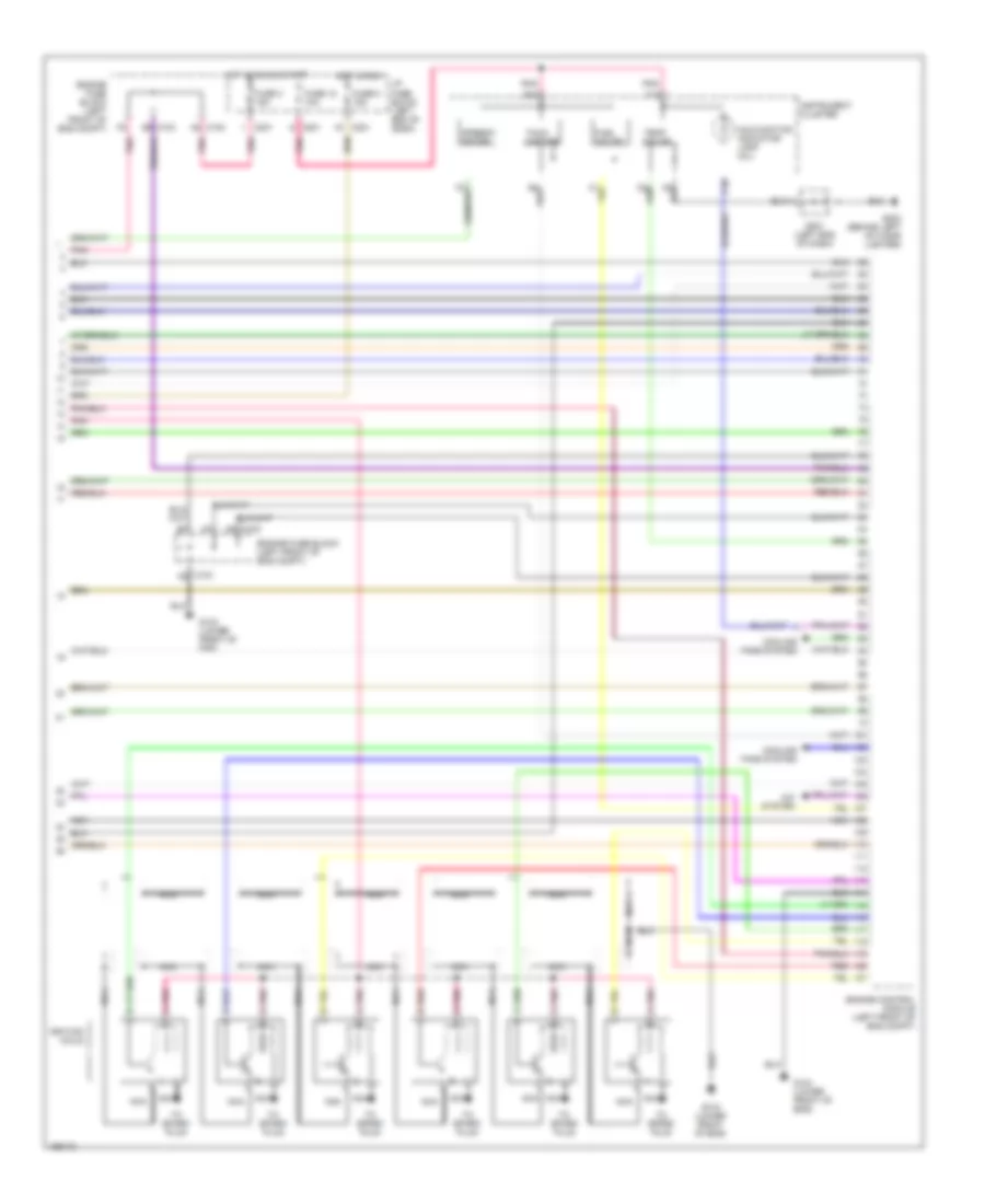
2.5L, Engine Performance Wiring Diagram (4 of 4) for Suzuki Verona S 2004
List of elements for 2.5L, Engine Performance Wiring Diagram (4 of 4) for Suzuki Verona S 2004:
- A/c system
- B14
- C nca
- C10
- C102
- C103
- C103 a8
- C14
- C201
- C6 c103
- Cooling fans system
- Engine control module (left front of eng compt)
- Engine fuse block (left front of eng compt)
- Fuel gauge
- Fuse 12 10a
- Fuse 3 15a
- Fuse 5 15a
- G103 (lower front of eng)
- G104 (lower front of eng)
- G202 (behind left of cigar lighter)
- Hot in run
- Hot in run & start
- I/p fuse block (left end of dash)
- Ignition coils
- Instrument cluster
- Malfunction indicator lamp (mil)
- Nca
- Pnk
- Pnk a
- Red
- Red b
- S201 (left end of dash)
- Speedo meter
- Tach- ometer
- Temp gauge
- To spark plug
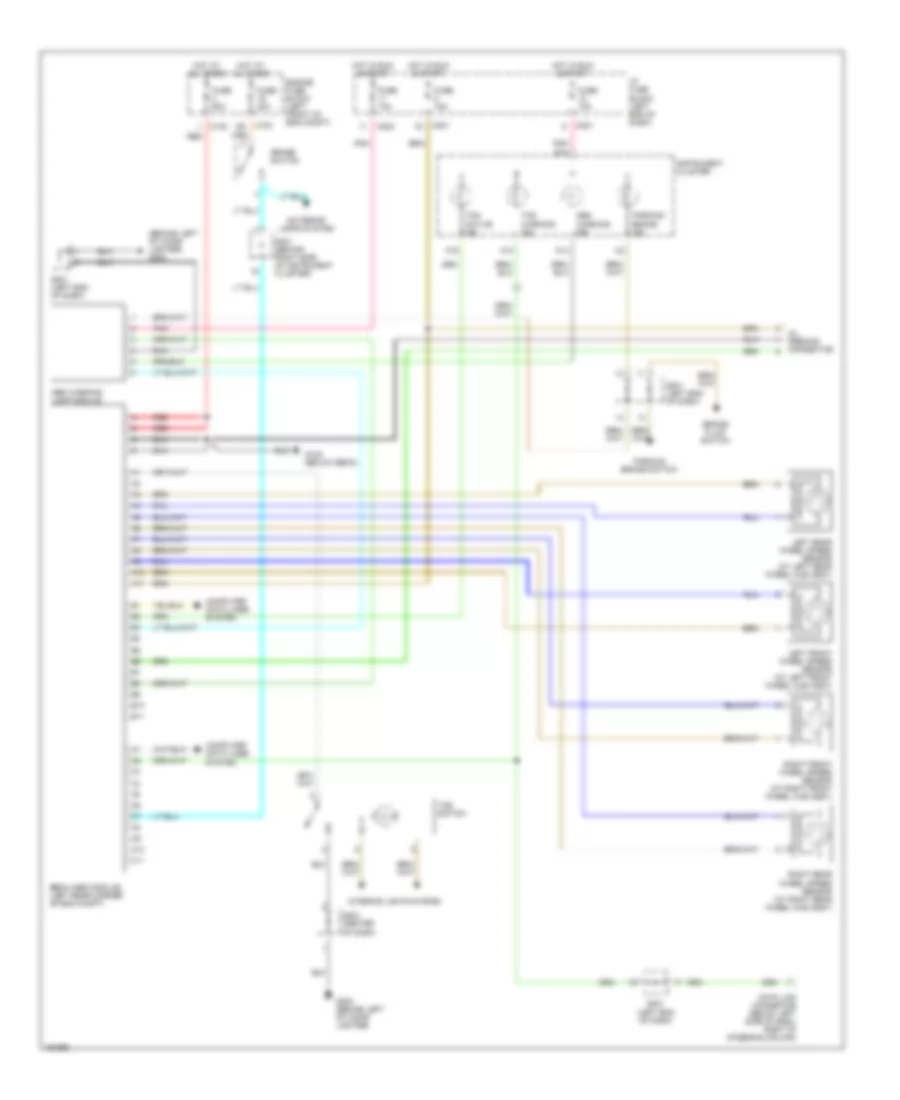
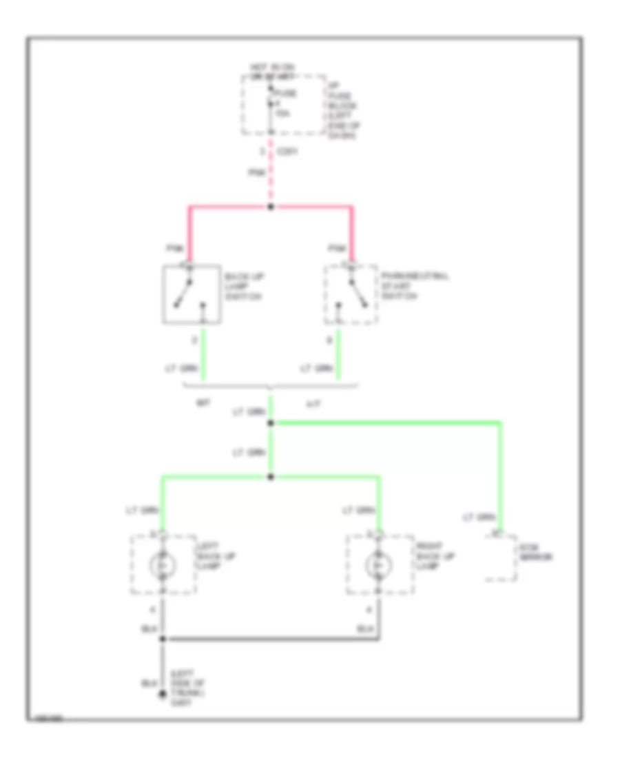
EXTERIOR LIGHTS
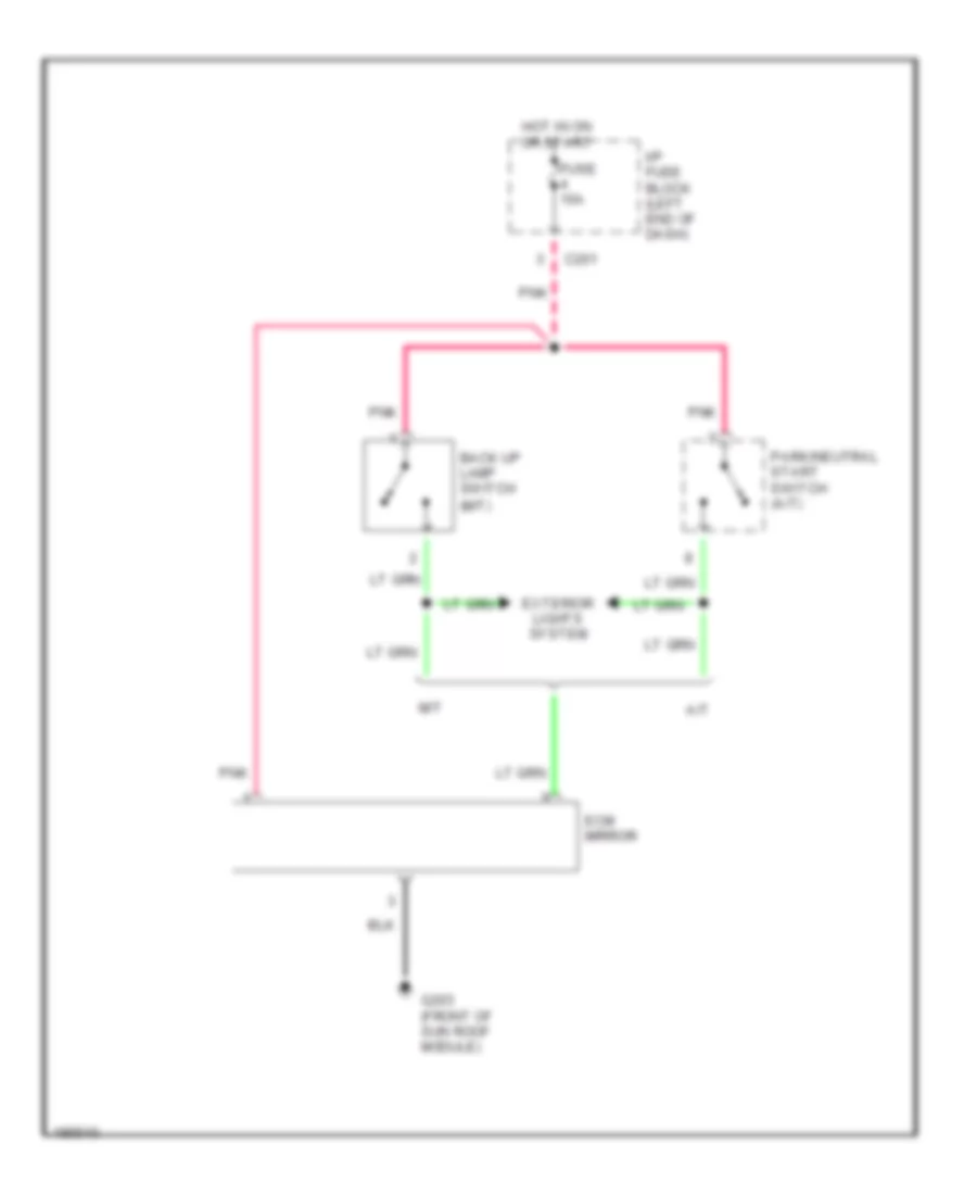
Back-up Lamps Wiring Diagram for Suzuki Verona S 2004
List of elements for Back-up Lamps Wiring Diagram for Suzuki Verona S 2004:
- (left side of trunk) g401
- A/t
- Back up lamp switch
- C201
- Ecm mirror
- Fuse 15a
- Hot in on or start
- I/p fuse block (left end of dash)
- Left back up lamp
- M/t
- Park/neutral start switch
- Pnk
- Right back up lamp
Exterior Lamps Wiring Diagram (1 of 2) for Suzuki Verona S 2004
List of elements for Exterior Lamps Wiring Diagram (1 of 2) for Suzuki Verona S 2004:
- (center of dash) s203
- A11
- Anti-lock brakes system
- B13
- B14
- B18
- Brake switch (lower left side of dash)
- C101
- C102
- C106
- C201
- C202
- Center high mount stop lamp
- Engine fuse block (left front of eng compt)
- Fuse 10a
- Fuse 20a
- Fuse 60a
- G202 (behind left of cigar lighter)
- G301 (under driver
- G303 (near left "c" pillar)
- Hazard switch
- Head
- Headlights system (drl relay)
- Hot at all times
- Hot in run
- Hot in run & start
- I/p fuse block (left end of dash)
- Illumination relay
- Instrument cluster
- Intelligent switching unit (lower left side of dash)
- Interior lights system
- Left turn
- Left turn indicator
- Light switch
- Mi-com
- Odo switch
- Off
- Park
- Pnk
- Red
- Right turn
- Right turn indicator
- S202 (right side of dash)
- S301 (behind right side of instrument cluster)
- Transmissions system
- Turn signal switch
Exterior Lamps Wiring Diagram (2 of 2) for Suzuki Verona S 2004
List of elements for Exterior Lamps Wiring Diagram (2 of 2) for Suzuki Verona S 2004:
- G101 (behind left head lamp)
- G102 (behind right head lamp)
- G303 (near left "c" pillar)
- G401 (left side of trunk)
- Left front parking lamp
- Left front turn signal lamp
- Left license plate lamp
- Left side turn signal lamp
- Left tail lamp
- Park
- Right front parking lamp
- Right front turn signal lamp
- Right license plate lamp
- Right side turn signal lamp
- Right tail lamp
- S301 (behind right side of instrument cluster)
- Stop
- Turn
GROUND DISTRIBUTION
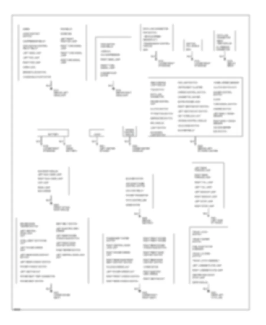
Ground Distribution Wiring Diagram for Suzuki Verona S 2004
List of elements for Ground Distribution Wiring Diagram for Suzuki Verona S 2004:
- "p" position switch
- A/c compressor
- A/d converter
- Abs warning lamp module
- Air bag control module
- Air conditioner control switch
- Audio
- Battery
- Blower motor
- Blower relay
- Brake fluid switch
- Center high mount stop lamp
- Cigarette lighter
- Clock
- Clutch switch
- Clutch switch (m/t)
- Compressor relay cooling fan control relay relay
- Cooling fan high relay
- Cruise control unit
- Data link connector
- Defroster switch
- Dimmer control switch
- Diode (d9)
- Driver door temper switch left central door lock unit
- Drl module
- Ebcm (abs module)
- Ecm
- Ecm mirror
- Extra power jack
- Fatc controller
- Fog lamp switch
- Fog relay
- Folding mirror unit
- Front turn signal lamp
- Fuel pump motor & sensor
- G101 (behind left headlamp)
- G102 (behind right headlamp)
- G103 (lower front of engine)
- G104 (lower front of engine)
- G105 (below ebcm)
- G106 (lower front of engine)
- G107 (near battery)
- G201 (left center of dash)
- G202 (behind left of cigar lighter)
- G203 (front of sun roof module)
- G204 (under center console)
- G205 (behind ashtray)
- G301 (under driver seat)
- G302 (under right front seat)
- G303 (near left "c" pillar)
- G401 (left side of trunk)
- Glove box lamp switch
- Hazard switch
- Hold mode switch
- Horn (hi)
- Horn (low)
- Ignition coil shield
- Instrument cluster
- Intelligent switching unit
- Key interlock unit
- Left backup lamp
- Left central door lock unit
- Left early crash sensor
- Left electric osrv mirror
- Left fog lamp
- Left front door contact switch
- Left front position lamp
- Left head lamp
- Left heating mat
- Left heating mat switch
- Left license plate lamp
- Left power mirror unit
- Left rear door contact switch
- Left rear parking lamp
- Left rear power window sub switch
- Left rear window switch
- Left stop lamp
- Left sun visor lamp
- Left tail lamp
- Light switch
- Lock unit
- Map lamp
- Max high relay
- Mirror control switch
- Mode motor
- Odo switch
- Oil feeding connector
- Pass temper switch
- Passenger tamper switch
- Pnp switch
- Power seat switch
- Power seat test connector
- Power transistor
- Power window switch
- Right backup lamp
- Right central door
- Right early crash sensor
- Right electric osrv mirror
- Right fog lamp
- Right front door contact switch
- Right front power right front power
- Right front window switch
- Right head lamp
- Right heating mat
- Right heating mat switch
- Right license plate lamp
- Right power mirror unit
- Right rear door contact switch
- Right rear door front seat contact switch
- Right rear parking lamp
- Right rear power window sub switch
- Right rear window switch
- Right stop lamp
- Right sun visor lamp
- Right tail lamp
- Right turn signal lamp
- Room lamp
- Seat belt switch
- Sensor (m/t)
- Side turn signal lamp
- Siren hood contact switch
- Ssps module
- Sun roof module
- Tcs switch
- Transmission control module
- Trunk latch assembly
- Trunk latch switch
- Trunk lid open switch
- Trunk tamper switch
- Turn signal switch
- Vehicle speed
- Washer pump motor
- Wheel speed sensor
- Windshield pump motor
- Wiper motor
HEADLIGHTS
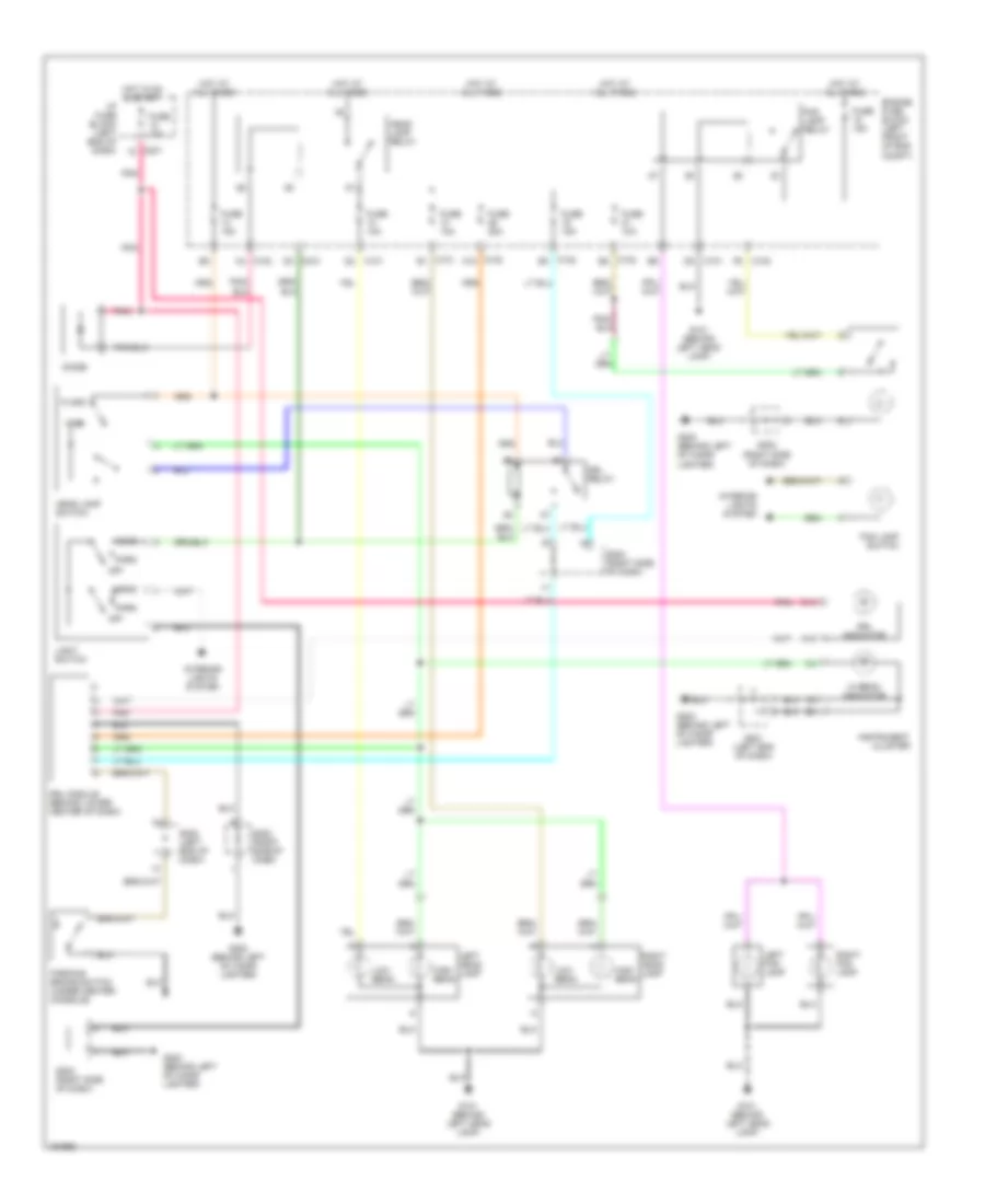
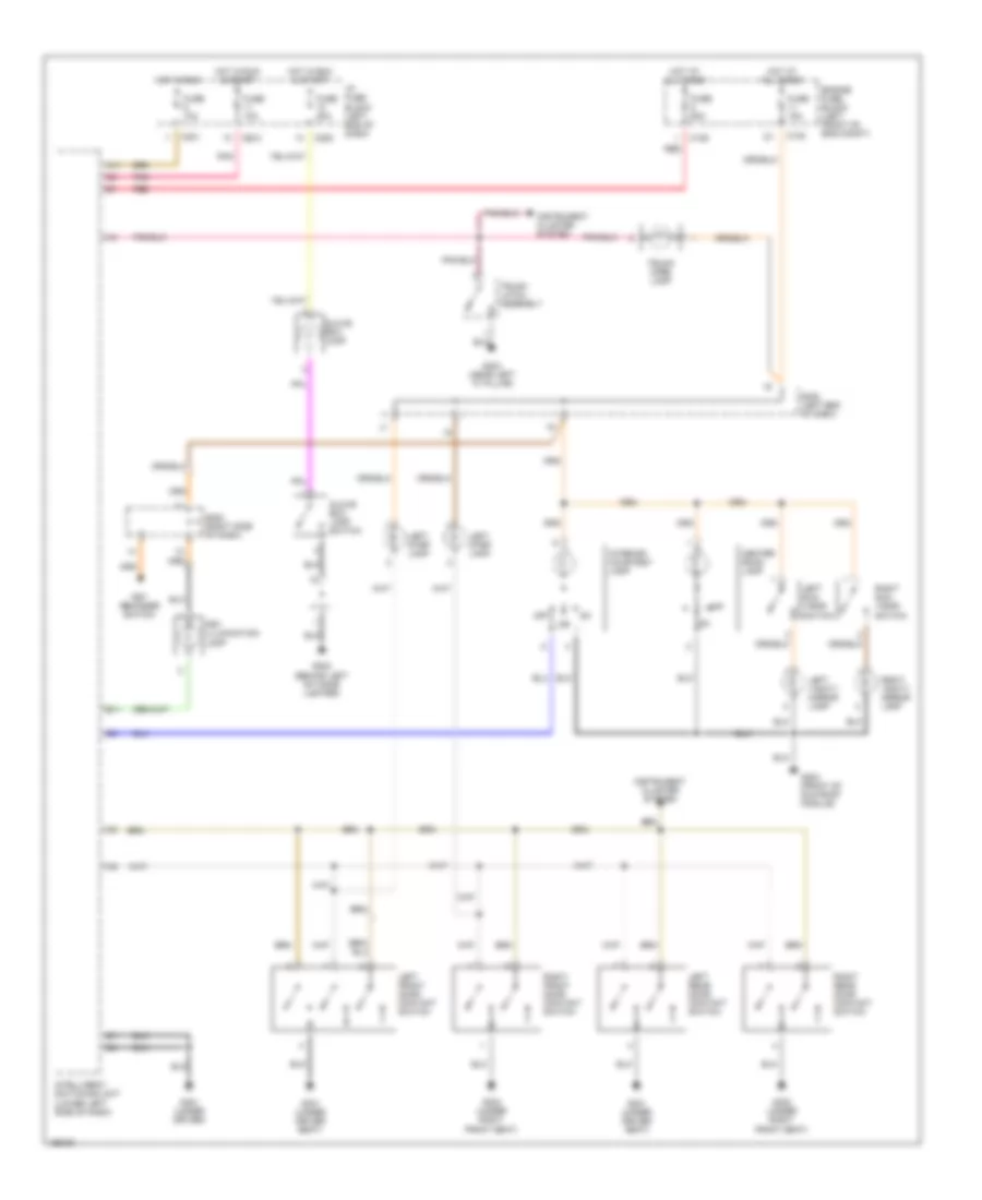
Headlamps & Fog Lamps Wiring Diagram for Suzuki Verona S 2004
List of elements for Headlamps & Fog Lamps Wiring Diagram for Suzuki Verona S 2004:
- A15
- A4 c102
- C101
- C101 b1
- C102
- C102 a10
- C102 b3
- C102 e8
- C14
- C201
- D3 c210
- Diode
- Drl indicator
- Drl module (behind lower center of dash)
- Drl relay
- Engine fuse block (left front of eng compt)
- Flash
- Fog lamp relay
- Fog lamp switch
- Fuse 10a
- Fuse 15a
- Fuse 20a
- G101 (behind left head lamp)
- G202 (behind left of cigar lighter)
- Head
- Head lamp relay
- Head lamp switch
- Hi beam indicator
- High
- High beam
- Hot at all times
- Hot in on & start
- I/p fuse block (left end of dash)
- Instrument cluster
- Interior lights system
- Left fog lamp
- Left head lamp
- Light switch
- Low beam
- Off
- Park
- Parking brake switch (under center console)
- Pnk
- Right fog lamp
- Right head lamp
- S201 (left end of dash)
- S202 (left end of dash)
- S202 (right side of dash)
HORN
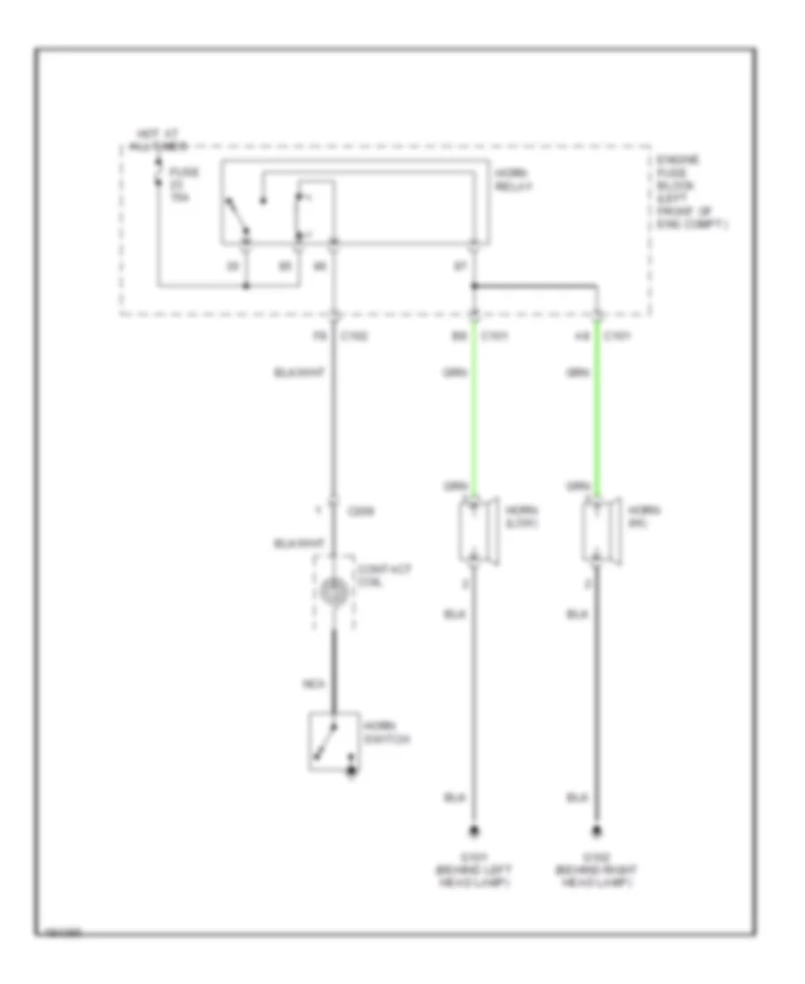
Horn Wiring Diagram for Suzuki Verona S 2004
List of elements for Horn Wiring Diagram for Suzuki Verona S 2004:
- C101
- C102
- C209
- Contact coil
- Engine fuse block (left front of eng compt)
- Fuse 15a
- G101 (behind left head lamp)
- G102 (behind right head lamp)
- Horn (hi)
- Horn (low)
- Horn relay
- Horn switch
- Hot at all times
- Nca
INSTRUMENT CLUSTER
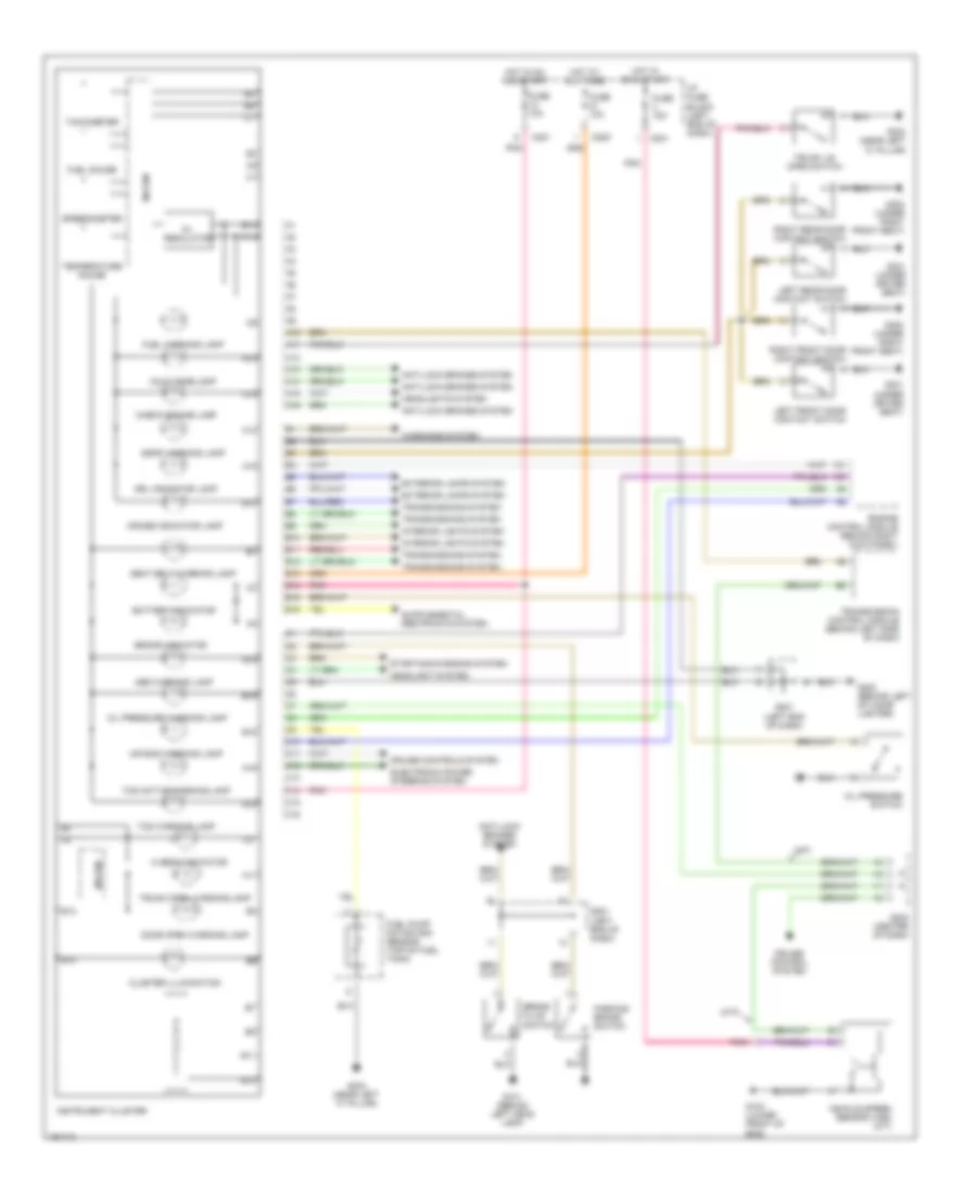
Instrument Cluster Wiring Diagram for Suzuki Verona S 2004
List of elements for Instrument Cluster Wiring Diagram for Suzuki Verona S 2004:
- (a/t)
- (m/t)
- 5v regulator
- A10
- A11
- A12
- A13
- A14
- A15
- A16
- Abs warning lamp
- Air bag warning lamp
- Anti-lock brakes system
- B10
- B11
- B12
- B13
- B14
- B15
- B16
- Battery indicator
- Brake fluid switch
- Brake indicator
- C10
- C11
- C12
- C13
- C14
- C15
- C16
- C201
- C205
- Check engine lamp
- Cluster illumination
- Cruise control system
- Cruise controls system
- Cruise indicator lamp
- Door open warning lamp
- Drl indicator lamp
- Electronic power steering system
- Engine control module (behind right kick panel)
- Exterior lamps system
- Fuel gauge
- Fuel pump motor and sensor (top of fuel tank)
- Fuel warning lamp
- Fuse 10a
- Fuse 15a
- G101 (behind left head lamp)
- G103 (lower front of eng)
- G202 (behind left of cigar lighter)
- G301 (under driver seat)
- G302 (under right front seat)
- G303 (near left "c" pillar)
- Headlight system
- Headlights system
- Hi beam indicator
- Hold mode lamp
- Hot at all times
- Hot in on & start
- Hot in on and start
- I/p fuse block (left end of dash)
- Instrument cluster
- Interior lights system
- Left front door contact switch
- Left rear door contact switch
- Mi-com
- Oil pressure switch
- Oil pressure warning lamp
- P r n d
- Parking brake switch
- Pnk
- Right front door contact switch
- Right rear door contact switch
- S201 (left end of dash)
- S202 (center of dash)
- Seat belt warning lamp
- Speedometer
- Ssps warning lamp
- Starting/charging system
- Tachometer
- Tcs active/warning lamp
- Tcs warning lamp
- Temperature gauge
- Transmission control module (behind left side of dash)
- Transmissions system
- Trunk lid open switch
- Trunk open warning lamp
- Vehicle speed sensor (vss) (m/t)
- Warnings system
INTERIOR LIGHTS
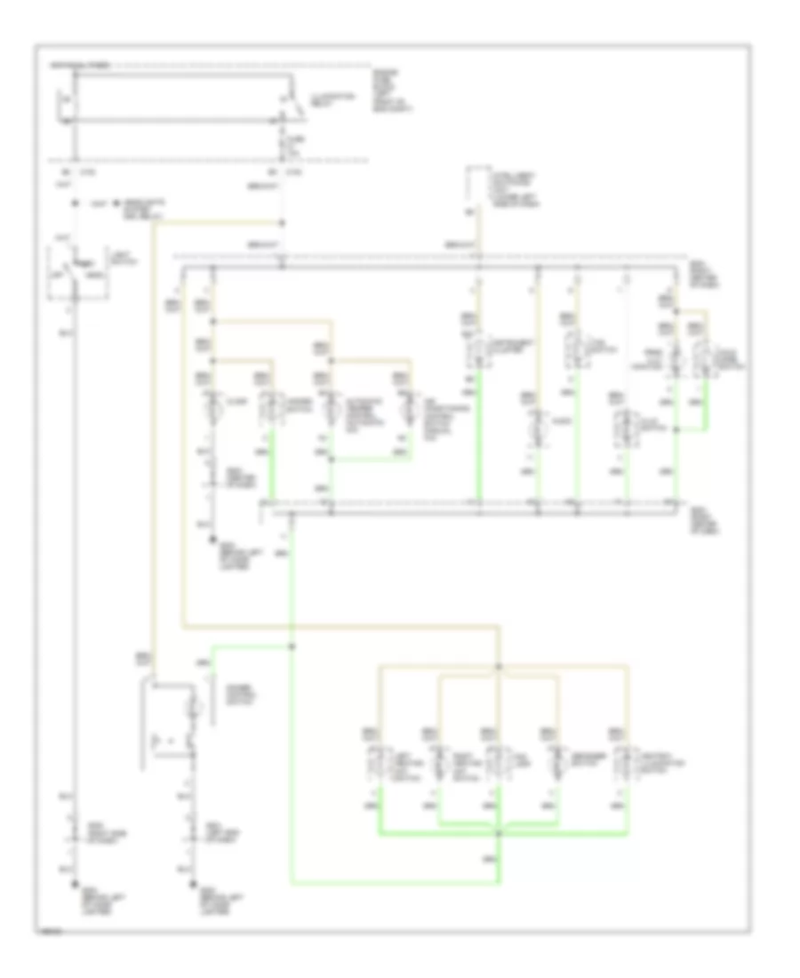
Courtesy Lamps Wiring Diagram for Suzuki Verona S 2004
List of elements for Courtesy Lamps Wiring Diagram for Suzuki Verona S 2004:
- A11
- B11
- C102
- C106
- C201
- C202
- C205
- Center room lamp
- Engine fuse block (left front of eng compt)
- Fuse 10a
- Fuse 15a
- Fuse 20a
- Fuse 60a
- G202 (behind left of cigar lighter)
- G203 (front of sun roof module)
- G301 (under driver seat)
- G301 (under driver)
- G302 (under right front seat)
- G303 (near left "c" pillar)
- Glove box lamp
- Glove box lamp switch
- Hot at all times
- Hot in run
- Hot in run & start
- I/p fuse block (left end of dash)
- Instrument cluster system
- Intelligent switching unit (lower left side of dash)
- Interior courtesy lamp
- Key illumination lamp
- Key reminder switch
- Left front door contact switch
- Left rear door contact switch
- Left step lamp
- Left sun visor switch
- Left vanity mirror lamp
- Off
- Pnk
- Red
- Right front door contact switch
- Right rear door contact switch
- Right sun visor switch
- Right vanity mirror lamp
- S202 (right side of dash)
- S302 (left end of dash)
- Trunk latch assembly
- Trunk open lamp
Instrument Illumination Wiring Diagram for Suzuki Verona S 2004
List of elements for Instrument Illumination Wiring Diagram for Suzuki Verona S 2004:
- Air conditioning control switch (manual a/c)
- Ashtray illumination switch
- Audio
- Automatic temper control (automatic a/c)
- B10
- C102
- Clock
- Defogger switch
- Dimmer control switch
- Engine fuse block (left front of eng compt)
- Fog lamp
- Fuse 10a
- G202 (behind left of cigar lighter)
- Hazard switch
- Head
- Headlights system (drl relay)
- Hlld switch
- Hold mode switch
- Hot at all times
- Illumination relay
- Instrument cluster
- Intelligent switching unit (lower left side of dash)
- Left heating mat switch
- Light switch
- Off
- Park
- Prnd illu- mination
- Right heating mat switch
- S201 (left end of dash)
- S202 (right side of dash)
- S203 (center of dash)
- S204 (right center of dash)
- Tcs switch
POWER DISTRIBUTION
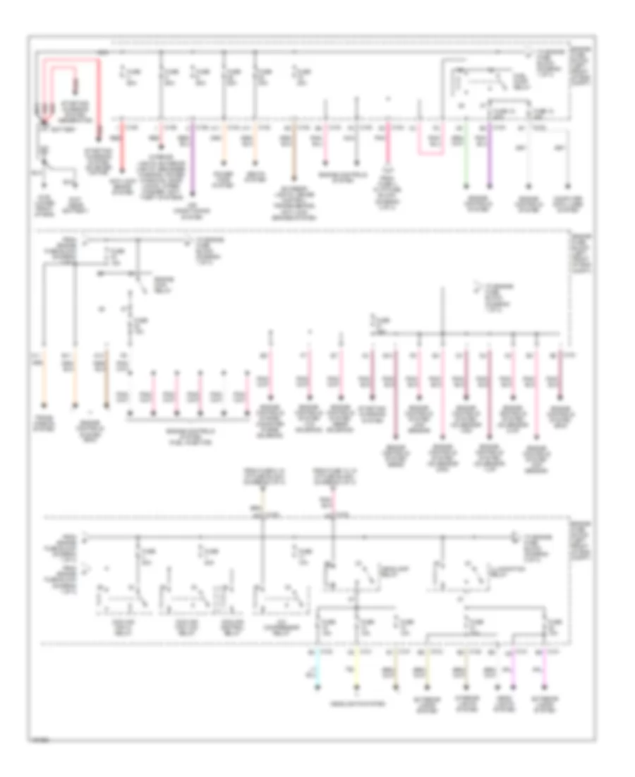
Power Distribution Wiring Diagram (1 of 3) for Suzuki Verona S 2004
List of elements for Power Distribution Wiring Diagram (1 of 3) for Suzuki Verona S 2004:
- A/c compressor relay
- A10
- A11
- Air conditioning system
- Anti-lock brake system
- B11
- B12
- Battery
- C101 b1
- C101 c9
- C101 d2
- C101 e9
- C102
- C102 a4
- C102 b3
- C102 b6
- C102 e2
- C102 e8
- C103
- C105
- C106
- C108 f8
- C11
- Computer data lines system
- Cooling control relay
- Cooling fan hi relay
- Cooling fan low relay
- Engine controls system
- Engine controls system (canister purge solenoid)
- Engine controls system (ecm)
- Engine controls system (eegr solenoid)
- Engine controls system (esds)
- Engine controls system (fuel injector)
- Engine controls system (maf sensor)
- Engine controls system (o2 sensor 1-dn)
- Engine controls system (o2 sensor 1-up)
- Engine controls system (o2 sensor 2-dn)
- Engine controls system (o2 sensor 2-up)
- Engine controls system (vis solenoid)
- Engine controls system cmp sensor)
- Engine fuse block (left front of eng compt)
- Engine main relay
- Exterior lamps system
- Exterior lights, cruise control, transmissions, anti-lock brakes system
- From engine fuse block (diagram 1 of 3)
- From fuse 12, in i/p fuse block, (diagram 3 of 3)
- From fuse 3 in i/p fuse block, (diagram 3 of 3)
- From fuse 6, in i/p fuse block, (diagram 2 of 3)
- Fuel pump relay
- Fuse 10a
- Fuse 12 20a
- Fuse 15 20a
- Fuse 15a
- Fuse 20a
- Fuse 30a
- Fuse 60a
- G106 (lower front of eng)
- G107 (near battery)
- Head- lights system
- Headlamp relay
- Headlights system
- Illumination relay
- Interior lights system
- Interior lights, exterior lights, defogger, warning, power windows, door locks, wiper/ washer, anti- theft systems
- Nca
- Pnk
- Power tops system
- Red
- Seats system
- Starting/ charging system
- Starting/ charging system (generator)
- Starting/ charging system (starter motor)
- To engine fuse block (diagram 1 of 3)
- To engine fuse block (diagram 2 of 3)
- Trans- mission system
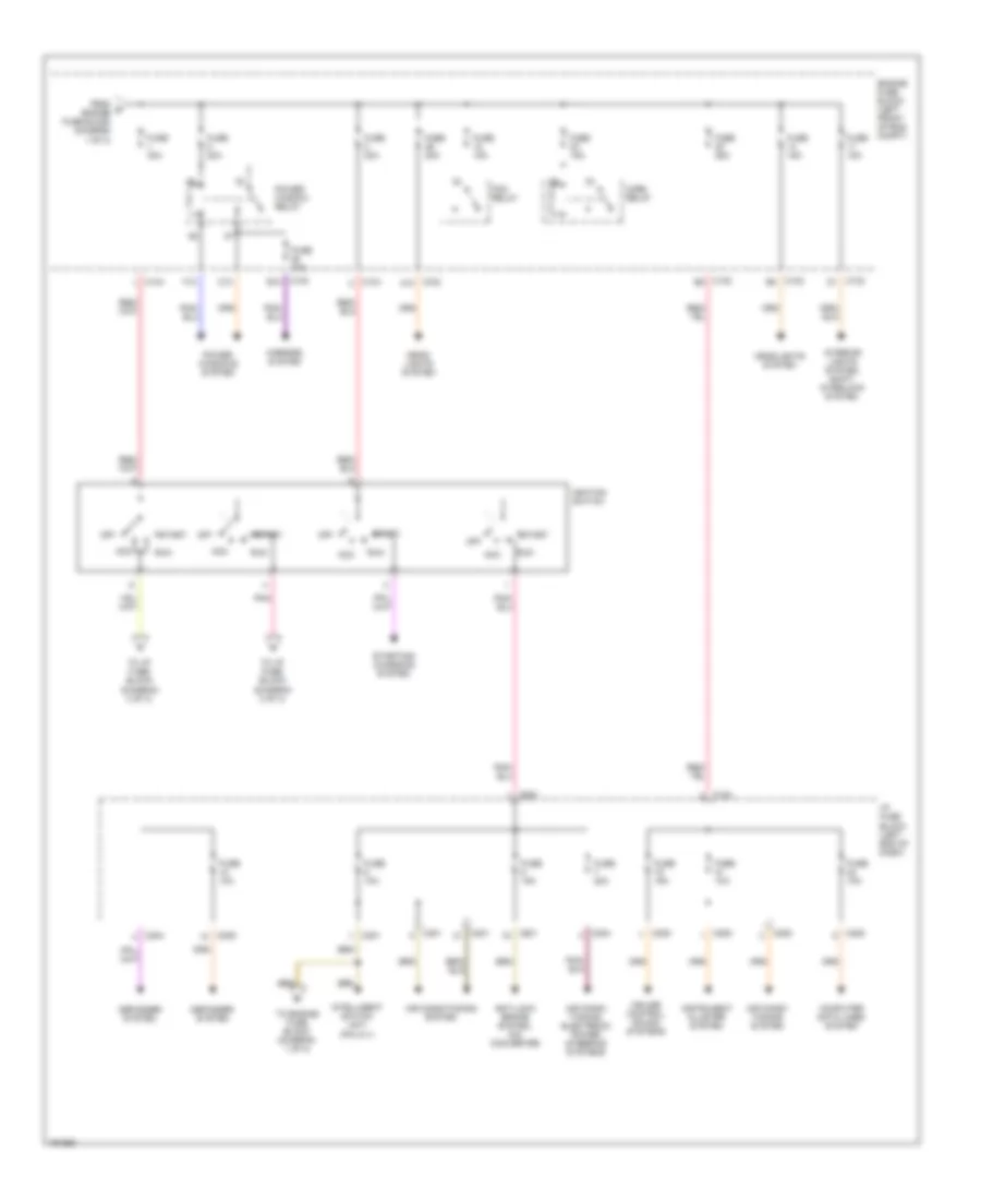
Power Distribution Wiring Diagram (2 of 3) for Suzuki Verona S 2004
List of elements for Power Distribution Wiring Diagram (2 of 3) for Suzuki Verona S 2004:
- Acc
- Air condi- tioning system
- Air condi- tioning, electronic power steering systems
- Air conditioning system
- Anti-lock brake system, a/d converter
- C10
- C102 a10
- C102 b10
- C102 b2
- C102 b5
- C102 d1
- C104
- C201
- C203
- C204
- C205
- Computer data lines system
- Cruise control, sound systems
- Defogger system
- Engine fuse block (left front of eng compt)
- F10
- Fog relay
- From d engine fuse block (diagram 1 of 3)
- Fuse 10a
- Fuse 15a
- Fuse 20a
- Fuse 25a
- Fuse 30a
- Head- lights system
- Headlights system
- Horn relay
- I/p fuse block (left end of dash)
- Ignition switch
- Instrument cluster system
- Intelligent switch unit (pin a11)
- Interior lights system, shift- interlock system
- Mirrors system
- Off
- Pnk
- Power window relay
- Power windows system
- Run
- Start
- Starting/ charging system
- To engine fuse block (diagram 1 of 3)
- To i/p fuse block (diagram 3 of 3)
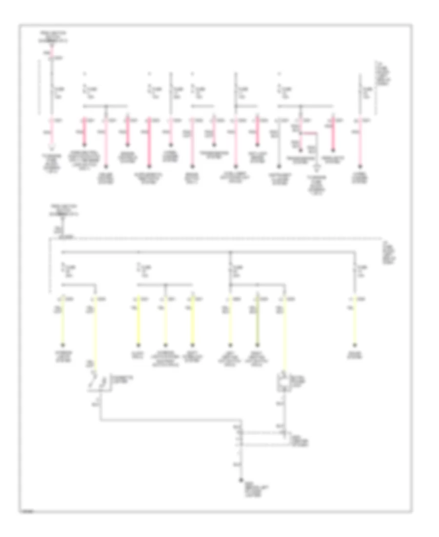
Power Distribution Wiring Diagram (3 of 3) for Suzuki Verona S 2004
List of elements for Power Distribution Wiring Diagram (3 of 3) for Suzuki Verona S 2004:
- Anti-lock brake system
- Brake switch (pin 1)
- C201
- C202
- C203
- C204
- C205
- Cigarette lighter
- Clock (pin 4)
- Cruise control system
- Engine controls system
- Extra power jack
- From ignition switch (diagram 2 of 3)
- Fuse 10a
- Fuse 15a
- Fuse 20a
- Fuse 25a
- G202 (behind left of cigar lighter)
- Headlights system
- I/p fuse block (left end of dash)
- Instrument cluster system
- Intelligent switching unit (pin d3)
- Interior lights system
- Interior lights system, sun roof switch (pin 6)
- Left heating mat switch (pin 5)
- Park/neutral position switch (pin 7), reverse lamp switch (pin 1)
- Pnk
- Right heating mat switch (pin 5)
- S203 (center of dash)
- Shift interlock system
- Sound system
- To engine fuse block (diagram 1 of 3)
- Transmissions system
- Wiper/ washer system
POWER DOOR LOCKS
Power Door Locks Wiring Diagram for Suzuki Verona S 2004
List of elements for Power Door Locks Wiring Diagram for Suzuki Verona S 2004:
- A10
- A11
- Anti-theft system
- C106
- C201
- C202
- Engine fuse block (left front of eng compt)
- Fuse 11 10a
- Fuse 5 60a
- Fuse 6 10a
- G301 (under driver seat)
- G302 (under right front seat)
- Hot at all times
- Hot in on
- Hot in on & run
- I/p fuse block (left end of dash)
- Intelligent switching unit (lower left side of dash)
- Left central door lock unit
- Left front door actuator
- Left rear door actuator
- Pnk
- Red
- Right central door lock unit
- Right front door actuator
- Right rear door actuator
- S302 (left end of dash)
POWER MIRRORS
Electrochromic Mirror Wiring Diagram for Suzuki Verona S 2004
List of elements for Electrochromic Mirror Wiring Diagram for Suzuki Verona S 2004:
- (m/t)
- A/t
- Back up lamp switch
- C201
- Ecm mirror
- Exterior lights system
- Fuse 15a
- G203 (front of sun roof module)
- Hot in on or start
- I/p fuse block (left end of dash)
- M/t
- Park/neutral start switch (a/t)
- Pnk
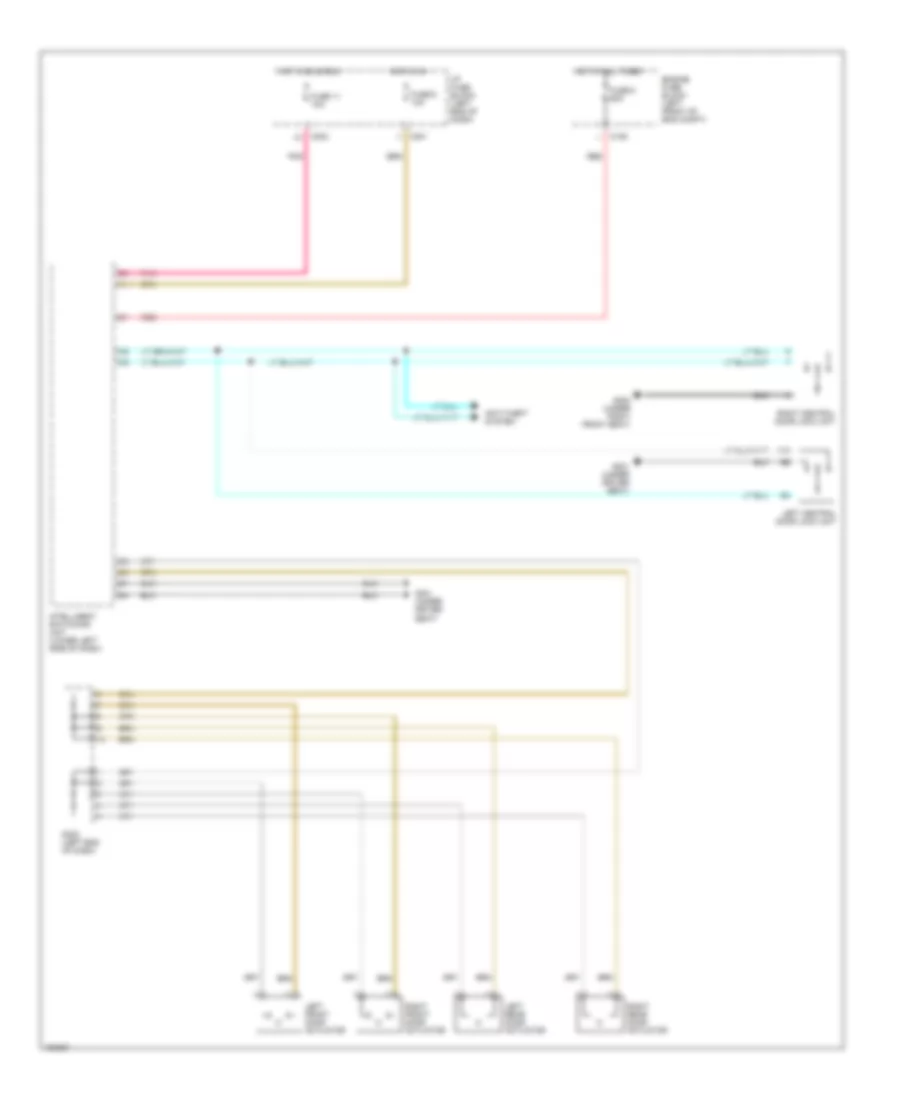
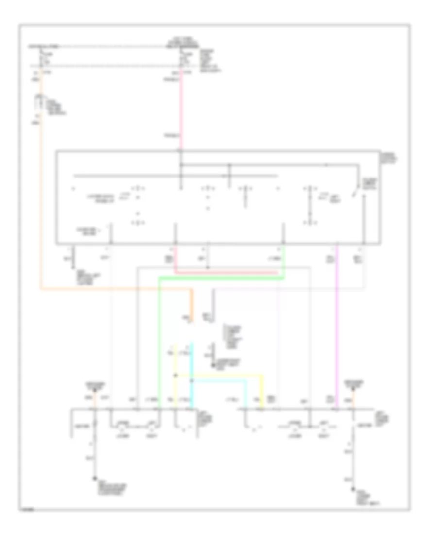
Power Mirrors Wiring Diagram for Suzuki Verona S 2004
List of elements for Power Mirrors Wiring Diagram for Suzuki Verona S 2004:
- (lower) down
- (raise) up
- (under right front seat) g302
- B10
- C102
- Co-driver
- Defogger system
- Driver
- Engine fuse block (left front of eng compt)
- Folding mirror switch
- Folding mirror unit (in right front door)
- Fuse 10a
- Fuse 15a
- G202 (behind left of cigar lighter)
- G301 (behind driver crossmember floor panel)
- G302 (under right front seat)
- Heater
- Hot at all time
- Hot when power window relay energized
- Left
- Left power mirror unit
- Lower
- Mirror control switch
- Right
- S302 (upper driver leg room)
- Upper
POWER SEATS
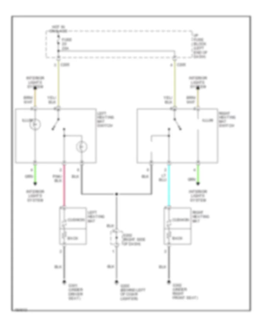
Heated Seats Wiring Diagram for Suzuki Verona S 2004
List of elements for Heated Seats Wiring Diagram for Suzuki Verona S 2004:
- Back
- C205
- Cushion
- Fuse 20a
- G202 (behind left of cigar lighter)
- G301 (under driver seat)
- G302 (under right front seat)
- Hot in on & acc
- I/p fuse block (left end of dash)
- Illum
- Interior lights system
- Left heating mat
- Left heating mat switch
- Right heating mat
- Right heating mat switch
- S202 (right side of dash)
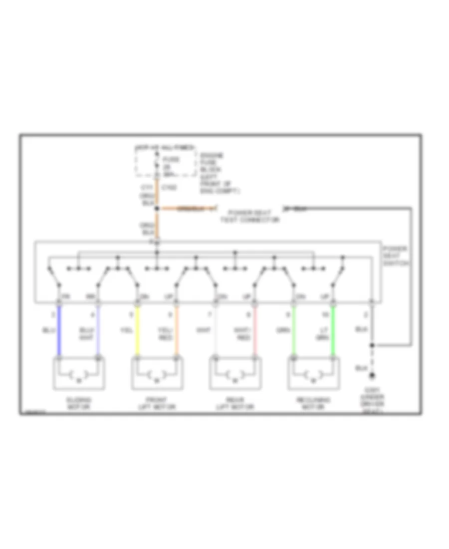
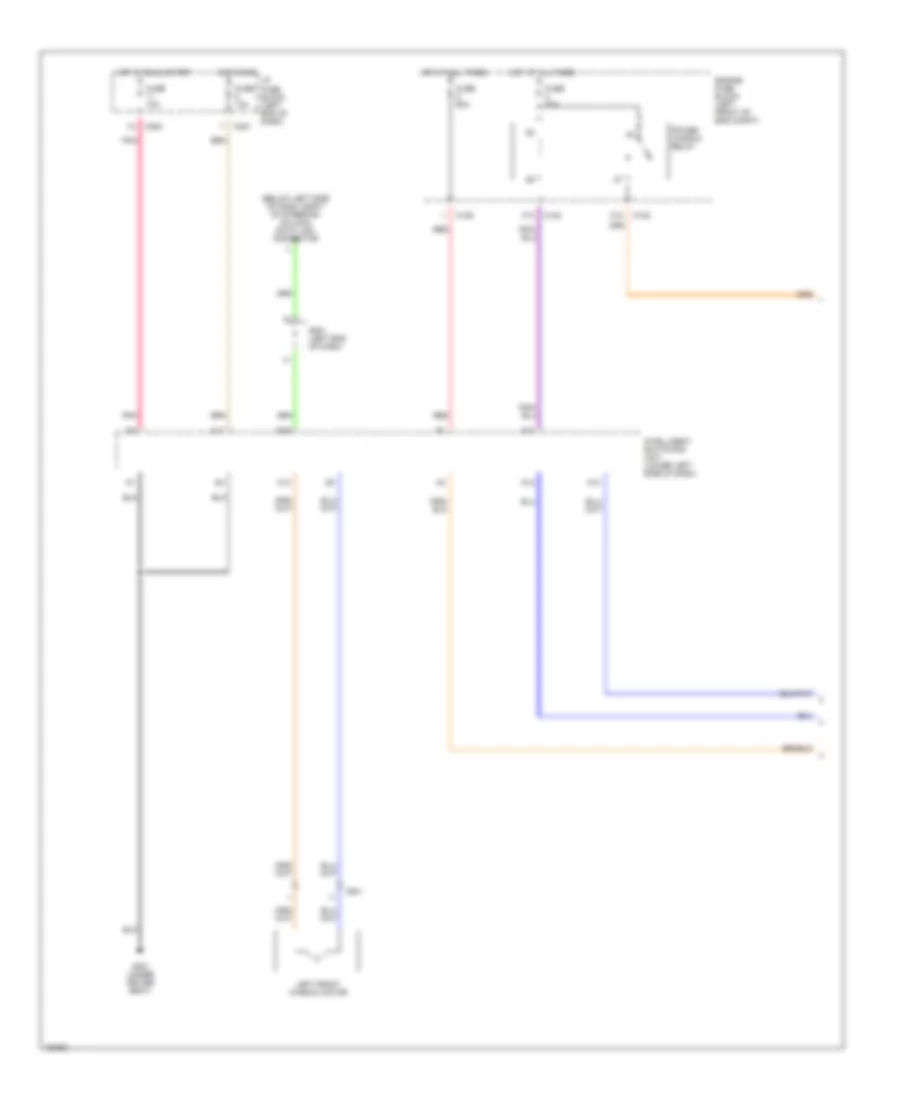
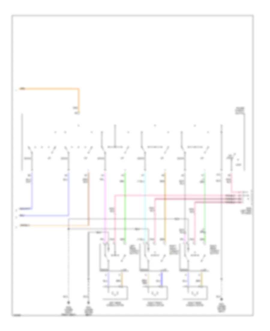
Power Seat Wiring Diagram for Suzuki Verona S 2004
List of elements for Power Seat Wiring Diagram for Suzuki Verona S 2004:
- C102
- C11
- Engine fuse block (left front of eng compt)
- Front lift motor
- Fuse 30a
- G301 (under driver seat)
- Hot at all times
- Power seat switch
- Power seat test connector
- Rear lift motor
- Reclining motor
- Sliding motor
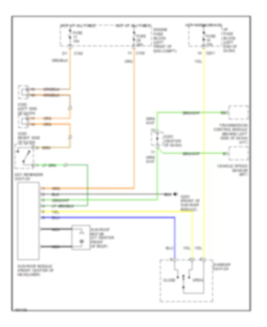
POWER TOP/SUNROOF
Power Top/Sunroof Wiring Diagram for Suzuki Verona S 2004
List of elements for Power Top/Sunroof Wiring Diagram for Suzuki Verona S 2004:
- C102
- C201
- Close
- Engine fuse block (left front of eng compt)
- Fuse 15a
- Fuse 20a
- G203 (front of sun roof module)
- Hot at all times
- Hot in run or acc
- I/p fuse block (left end of dash)
- Key reminder switch
- Nca
- Open
- S202 (right side of dash)
- S203 (center of dash)
- S302 (left end of dash)
- Sun roof module (front center of headliner)
- Sun roof motor (at center front of roof)
- Sunroof switch
- Transmission control module (behind left side of dash) (a/t)
- Vehicle speed sensor (m/t)
POWER WINDOWS
Power Windows Wiring Diagram (1 of 2) for Suzuki Verona S 2004
List of elements for Power Windows Wiring Diagram (1 of 2) for Suzuki Verona S 2004:
- (below left side of dash, right of steering column) data link connector
- A10
- A11
- A12
- A13
- B19
- C10
- C102
- C106
- C201
- C202
- C351
- Engine fuse block (left front of eng compt)
- F10
- Fuse 10a
- Fuse 20a
- Fuse 60a
- G301 (under driver seat)
- Hot at all times
- Hot in run
- Hot in run & start
- I/p fuse block (left end of dash)
- Intelligent switching unit (lower left side of dash)
- Left front window motor
- Pnk
- Power window relay
- Red
- S201 (left end of dash)
Power Windows Wiring Diagram (2 of 2) for Suzuki Verona S 2004
List of elements for Power Windows Wiring Diagram (2 of 2) for Suzuki Verona S 2004:
- A10
- Down
- G301 (under driver seat)
- G302 (under right front seat)
- Left rear window motor
- Left rear window switch
- Lock
- Pnk
- Power window switch
- Right front window motor
- Right front window switch
- Right rear window motor
- Right rear window switch
- S302 (left end of dash)
- Un- lock
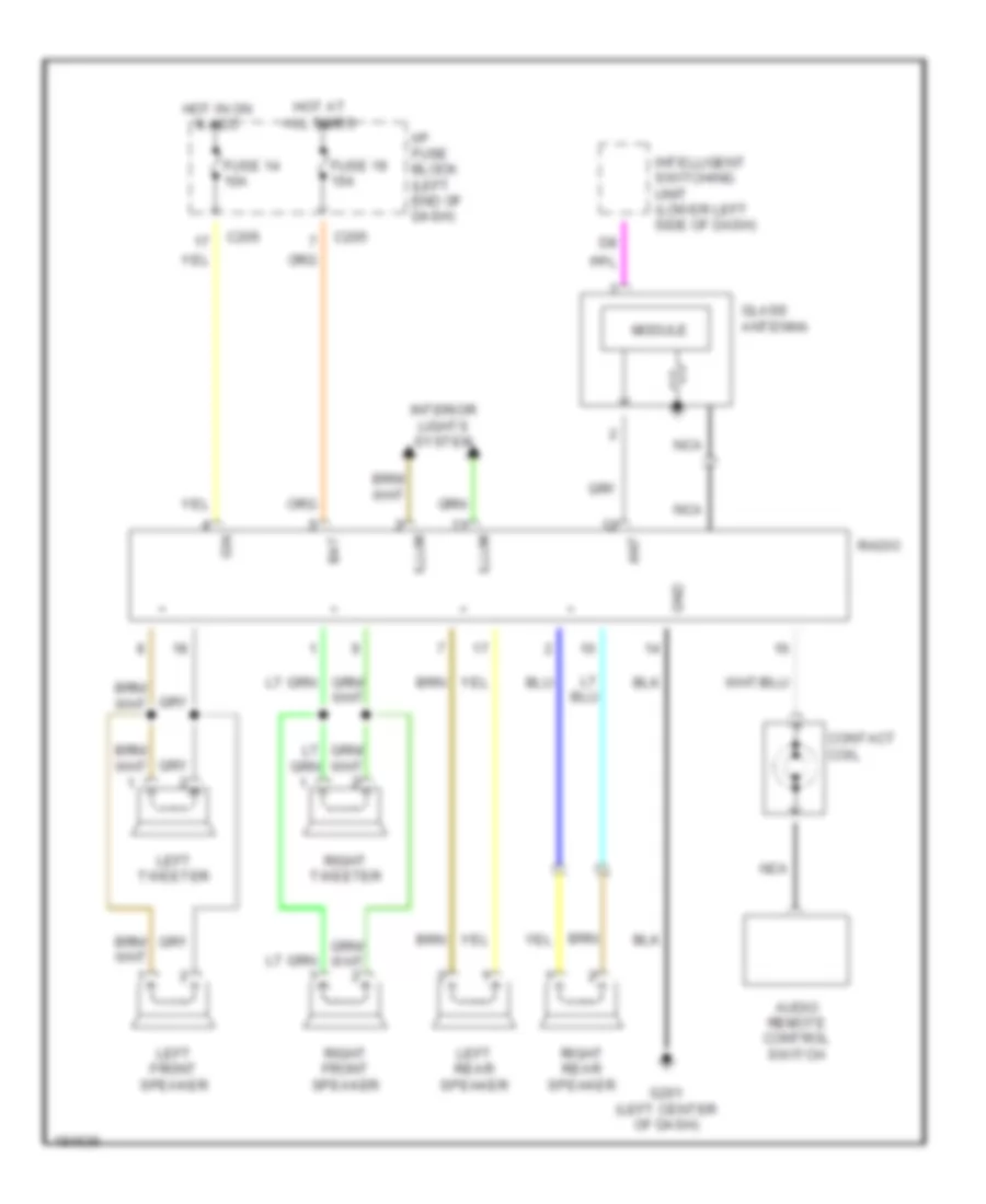
RADIO
Radio Wiring Diagram for Suzuki Verona S 2004
List of elements for Radio Wiring Diagram for Suzuki Verona S 2004:
- Ant
- Audio remote control switch
- Bat
- C205
- Contact coil
- Fuse 14 10a
- Fuse 19 15a
- G201 (left center of dash)
- Glass antenna
- Gnd
- Hot at all times
- Hot in on & acc
- I/p fuse block (left end of dash)
- Ign
- Illum
- Intelligent switching unit (lower left side of dash)
- Interior lights system
- Left front speaker
- Left rear speaker
- Left tweeter
- Module
- Nca
- Radio
- Right front speaker
- Right rear speaker
- Right tweeter
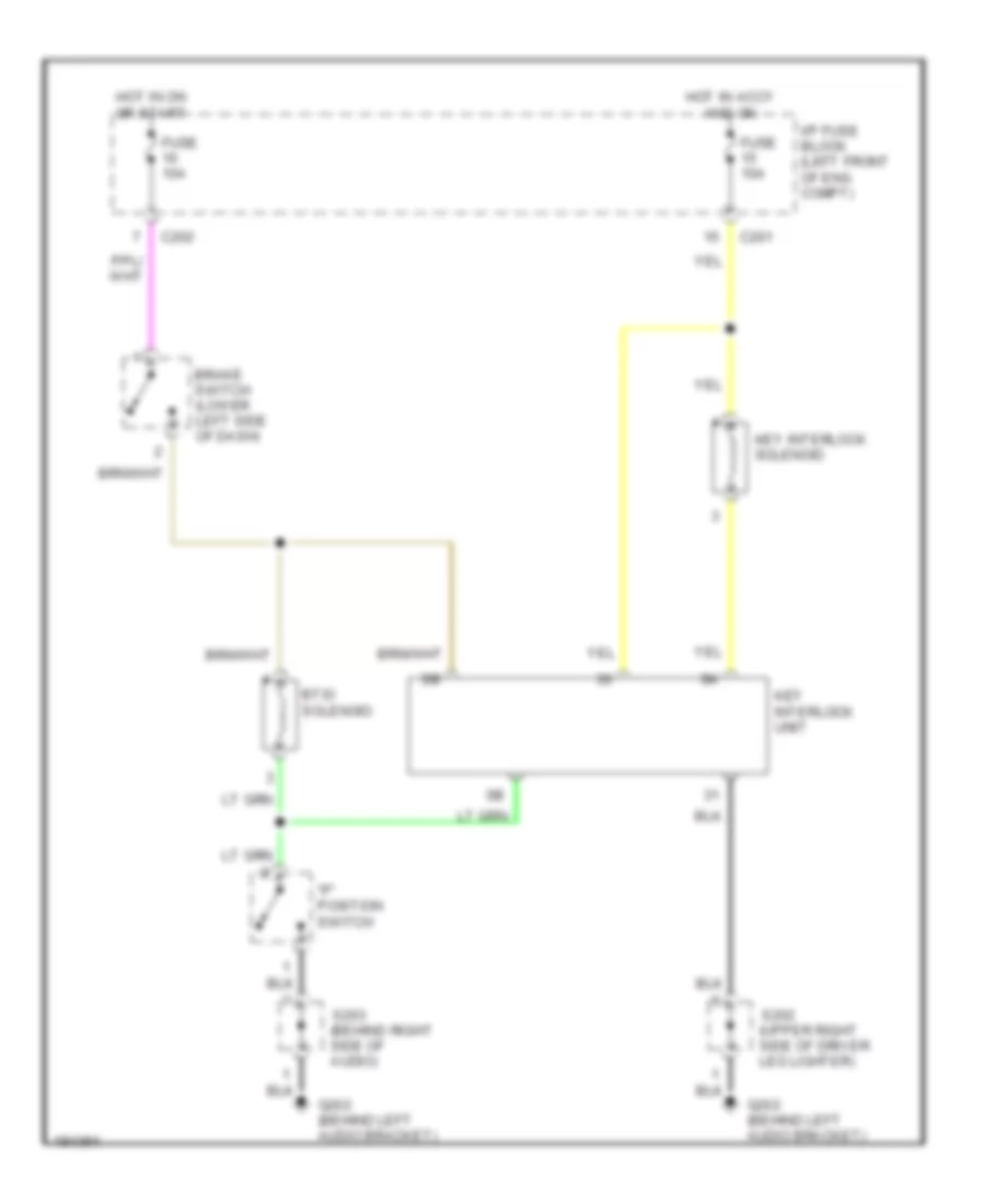
SHIFT INTERLOCK
Shift Interlock Wiring Diagram for Suzuki Verona S 2004
List of elements for Shift Interlock Wiring Diagram for Suzuki Verona S 2004:
- "p" position switch
- Brake switch (lower left side of dash)
- Btsi solenoid
- C201
- C202
- Fuse 10a
- G202 (behind left audio bracket)
- Hot in accy and on
- Hot in on or start
- I/p fuse block (left front of eng compt)
- Key interlock solenoid
- Key interlock unit
- S202 (upper right side of driver leg lighter)
- S203 (behind right side of audio)
STARTING/CHARGING
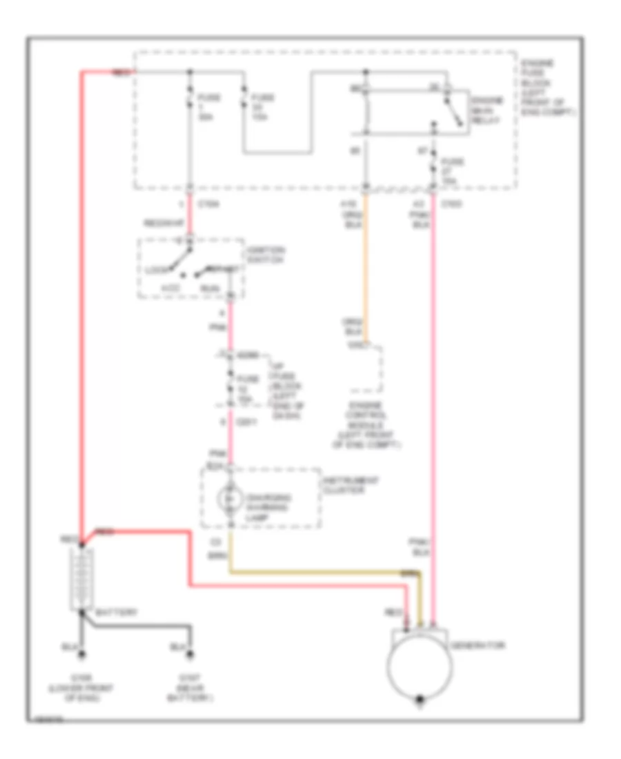
Charging Wiring Diagram for Suzuki Verona S 2004
List of elements for Charging Wiring Diagram for Suzuki Verona S 2004:
- A10
- Acc
- B14
- Battery
- C103
- C104
- C201
- C203
- Charging warning lamp
- Engine control module (left front of eng compt)
- Engine fuse block (left front of eng compt)
- Engine main relay
- Fuse 10a
- Fuse 15a
- Fuse 30a
- G106 (lower front of eng)
- G107 (near battery)
- Generator
- I/p fuse block (left end of dash)
- Ignition switch
- Instrument cluster
- Lock
- Pnk
- Red
- Run
- Start
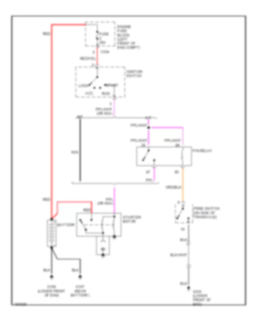
Starting Wiring Diagram for Suzuki Verona S 2004
List of elements for Starting Wiring Diagram for Suzuki Verona S 2004:
- A/t
- Acc
- Battery
- C104
- Engine fuse block (left front of eng compt)
- Fuse 30a
- G103 (lower front of eng)
- G106 (lower front of eng)
- G107 (near battery)
- Ignition switch
- Lock
- M/t
- Nca
- P/n relay
- Prnd switch (on side of transaxle)
- Red
- Run
- Start
- Starter motor
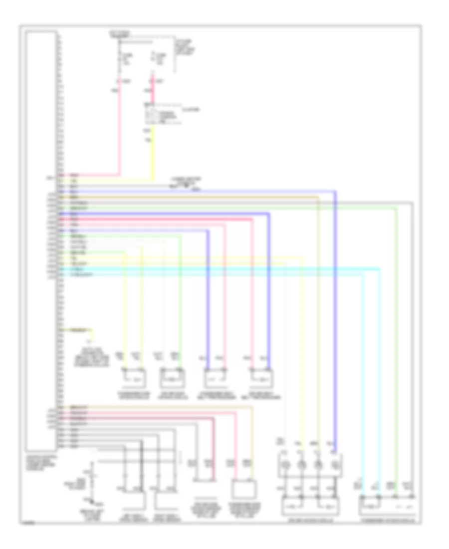
SUPPLEMENTAL RESTRAINTS
Supplemental Restraints Wiring Diagram for Suzuki Verona S 2004
List of elements for Supplemental Restraints Wiring Diagram for Suzuki Verona S 2004:
- (behind left of cigar lighter
- (under center console)
- Air bag control module (sdm) (under center console)
- Air bag warning ind
- B14
- B16
- C201
- C202
- Cluster
- Data link connector (below left side of dash, right of steering column)
- Driver air bag module
- Driver seat belt pretensioner
- Driver side air bag module
- Driver side air bag sensor (base of left "b" pillar)
- Fuse f12 10a
- Fuse f8 10a
- G202
- G204
- High
- Hot in run or start
- I/p fuse block (left end of dash)
- Ign +
- Left early crash sensor
- Low
- Nca
- Passenger air bag module
- Passenger seat belt pretensioner
- Passenger side air bag module
- Passenger side air bag sensor (base of right "b" pillar)
- Pnk
- Right early crash sensor
- S202 (right side of dash)
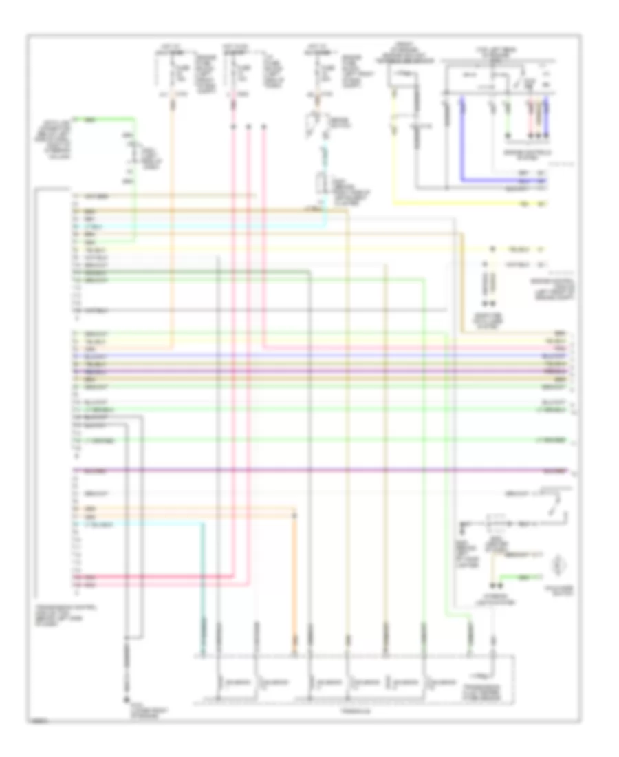
TRANSMISSION
Transmission Wiring Diagram (1 of 2) for Suzuki Verona S 2004
List of elements for Transmission Wiring Diagram (1 of 2) for Suzuki Verona S 2004:
- (front of engine) engine coolant temperature sensor
- (top left rear of engine) mtia
- A11
- Brake switch
- C102
- C103
- C119
- C202
- Computer data lines system
- Data link connector (below left side of dash, right of steering column)
- Engine control module (left front of engine compt)
- Engine controls system
- Engine fuse block (left front of eng compt)
- Fuse 10a
- Fuse 15a
- Fuse 20a
- G103 (lower front of engine)
- G202 (behind left of cigar lighter)
- Hold mode switch
- Hot at all times
- Hot in on & start
- I/p fuse block (left end of dash)
- Idle sw
- Interior lights system
- Pnk
- Red
- S201 (left end of dash)
- S203 (center of dash)
- S301 (behind right side of instrument cluster)
- Solenoid
- Transaxle
- Transmission control module (tcm) (behind left side of dash)
- Transmission fluid temper- ature sensor
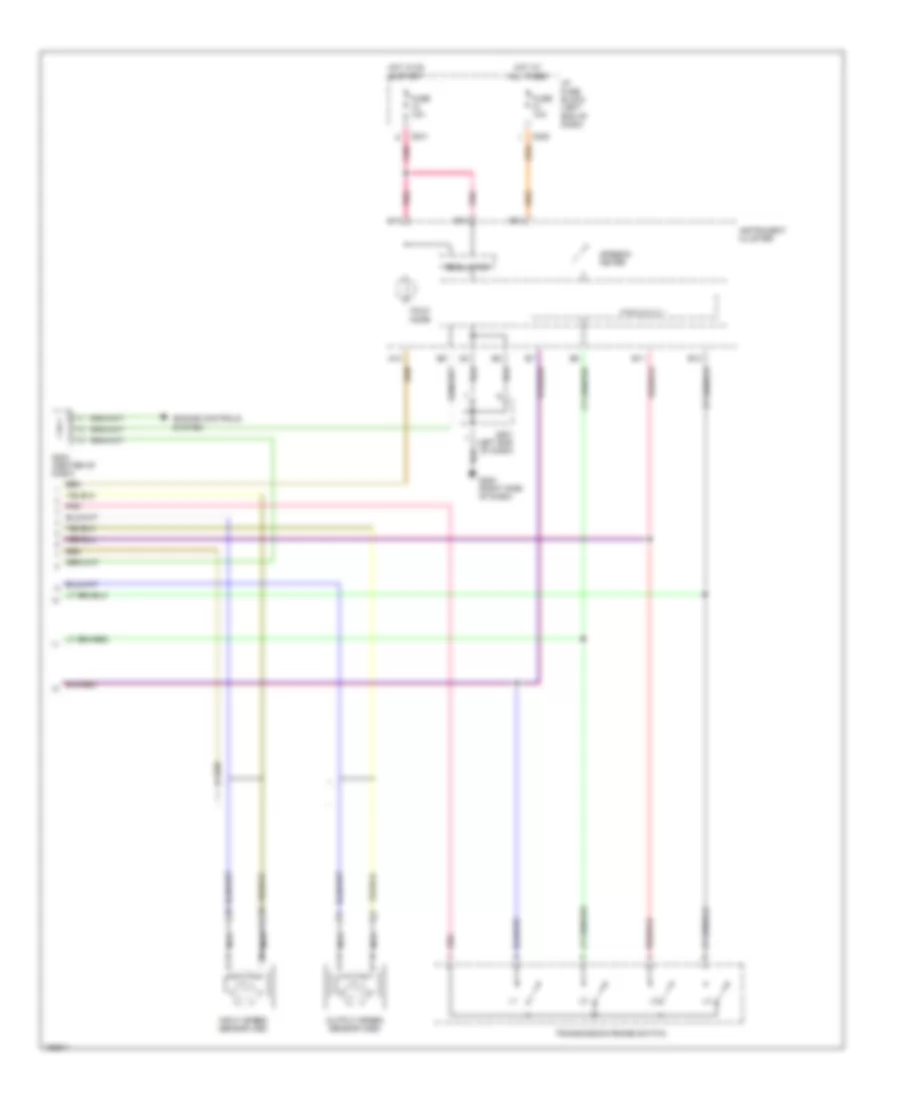
Transmission Wiring Diagram (2 of 2) for Suzuki Verona S 2004
List of elements for Transmission Wiring Diagram (2 of 2) for Suzuki Verona S 2004:
- A10
- B11
- B12
- B13
- B14
- C14
- C201
- C205
- Engine controls system
- Fuse 10a
- G202 (right side of dash)
- Hold mode
- Hot at all times
- Hot in on & start
- I/p fuse block (left end of dash)
- Input speed sensor (iss)
- Instrument cluster
- Nca
- Output speed sensor (oss)
- P r n d 3 2 1
- Pnk
- Regulator
- S201 (left end of dash)
- S203 (center of dash)
- Speedo- meter
- Transmission range switch
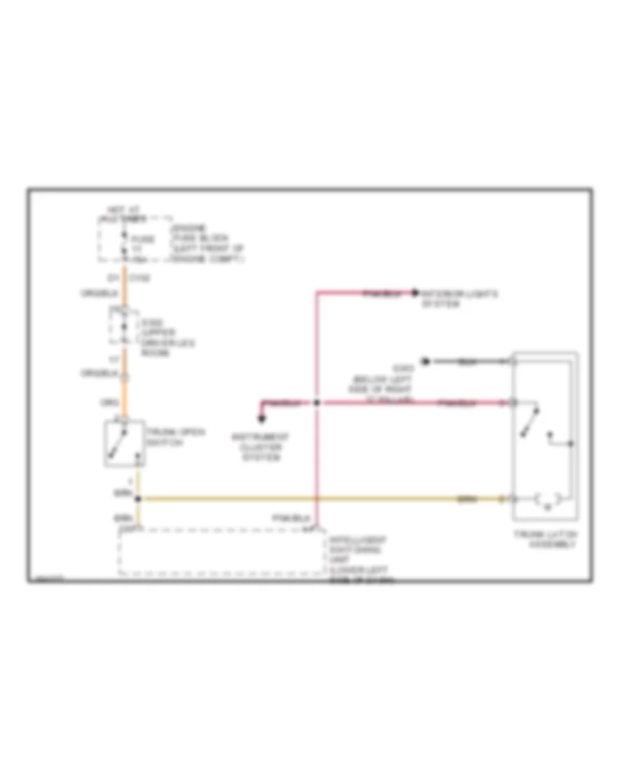
TRUNK, TAILGATE, FUEL DOOR
Trunk Release Wiring Diagram for Suzuki Verona S 2004
List of elements for Trunk Release Wiring Diagram for Suzuki Verona S 2004:
- (below left side of right "c" pillar)
- D1 c102
- Engine fuse block (left front of engine compt)
- Fuse 15a
- G303
- Hot at all times
- Instrument cluster system
- Intelligent switching unit (lower left side of dash)
- Interior lights system
- S302 (upper driver leg room)
- Trunk latch assembly
- Trunk open switch
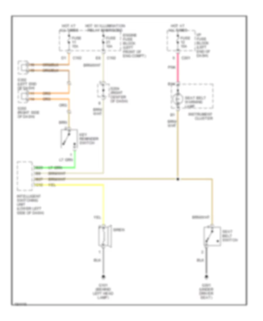
WARNING SYSTEMS
Warning Systems Wiring Diagram for Suzuki Verona S 2004
List of elements for Warning Systems Wiring Diagram for Suzuki Verona S 2004:
- B14
- B23
- B27
- C102
- C12
- C201
- Engine fuse block (left front of eng compt)
- Fuse 10a
- Fuse 15a
- G101 (behind left head lamp)
- G301 (under driver seat)
- Hot at all times
- Hot w/ illumination relay energized
- I/p fuse block (left end of dash)
- Instrument cluster
- Intelligent switching unit (lower left side of dash)
- Key reminder switch
- Pnk
- S202 (right side of dash)
- S204 (right center of dash)
- S302 (left end of dash)
- Seat belt switch
- Seat belt warning lamp
- Siren
WIPER/WASHER
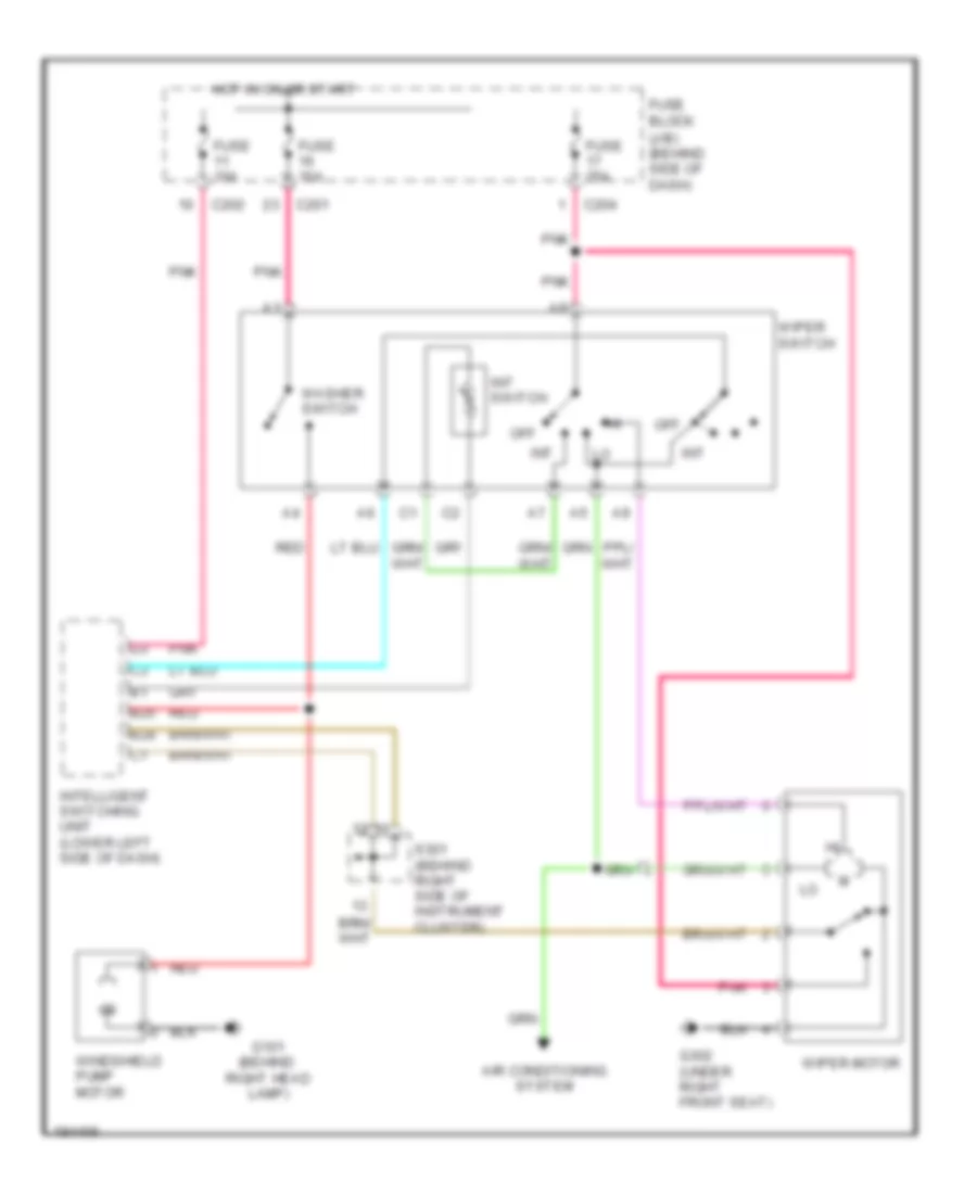
Wiper/Washer Wiring Diagram for Suzuki Verona S 2004
List of elements for Wiper/Washer Wiring Diagram for Suzuki Verona S 2004:
- (j/b) (behind side of dash)
- Air conditioning system
- B25
- B28
- C201
- C202
- C204
- Fuse 10a
- Fuse 25a
- Fuse block
- G101 (behind right head lamp)
- G302 (under right front seat)
- Hot in on or start
- Int
- Int switch
- Intelligent switching unit (lower left side of dash)
- Off
- Pnk
- Red
- S301 (behind right side of instrument cluster)
- Washer switch
- Windshield pump motor
- Wiper motor
- Wiper switch