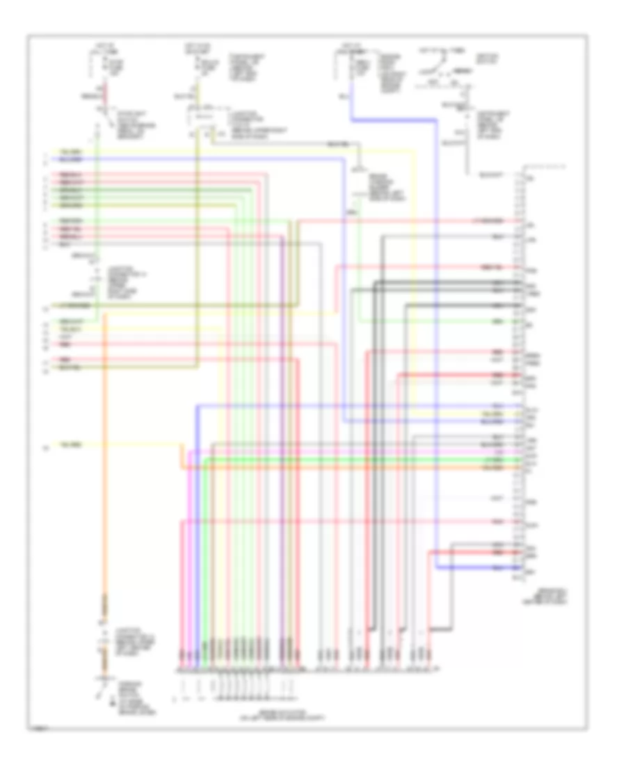
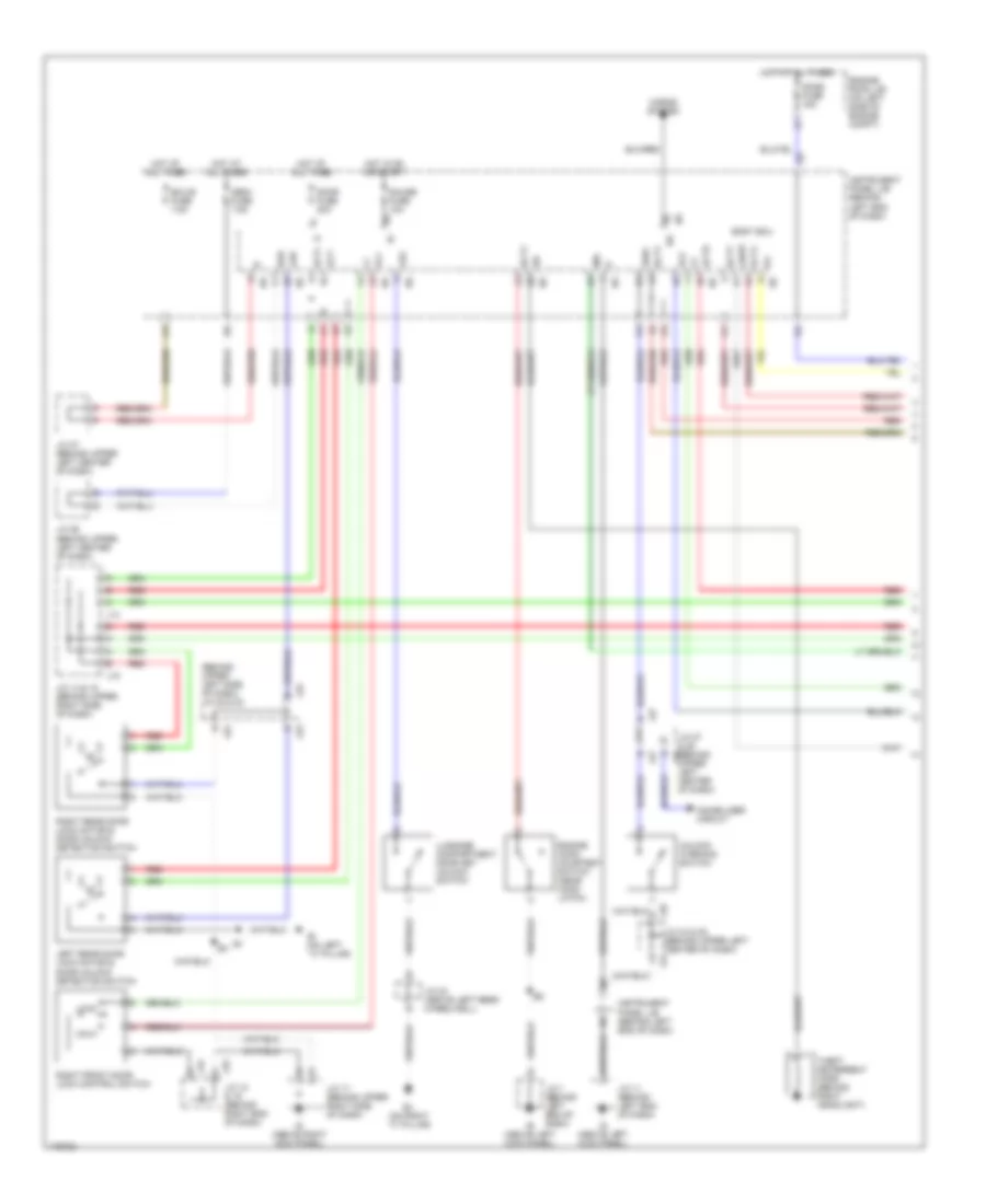
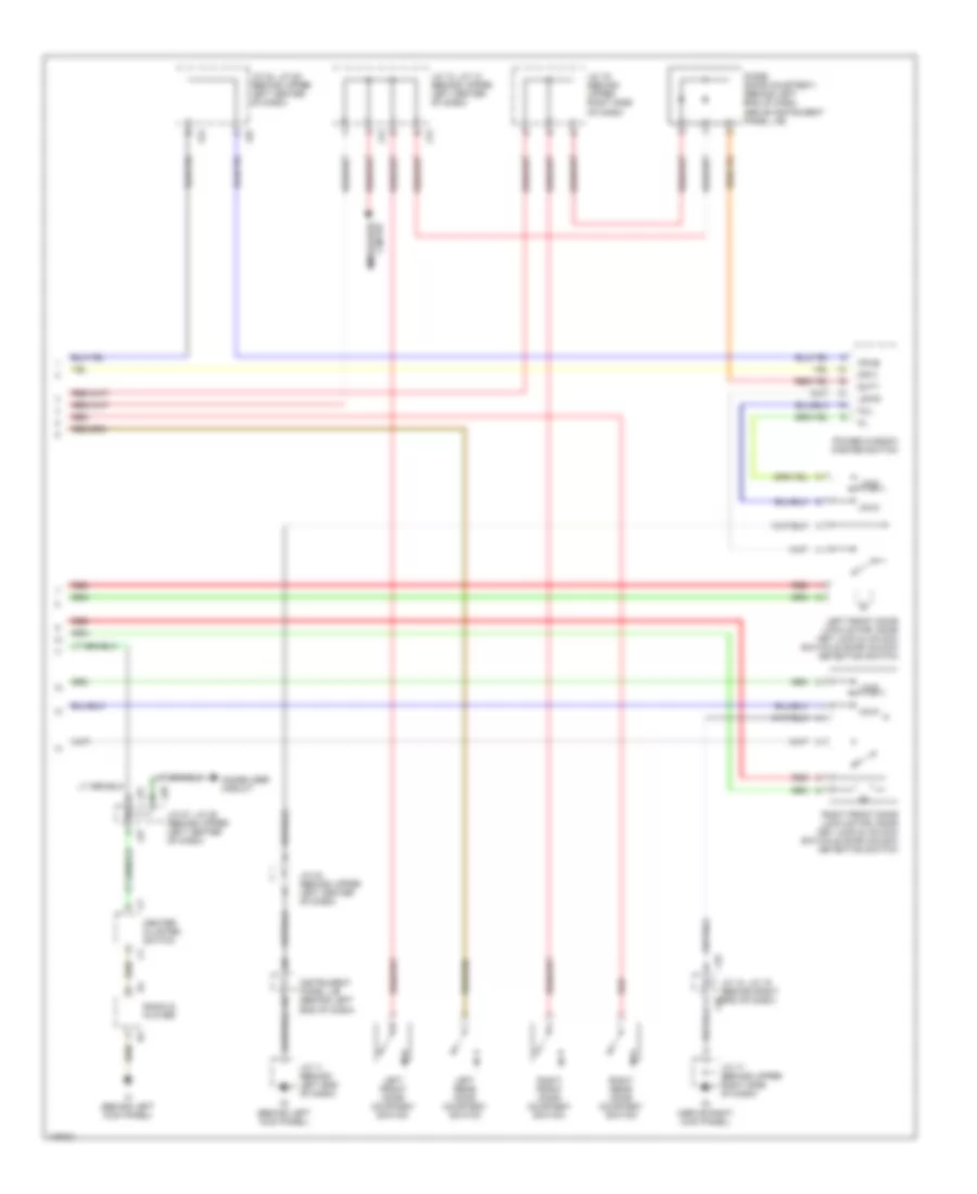
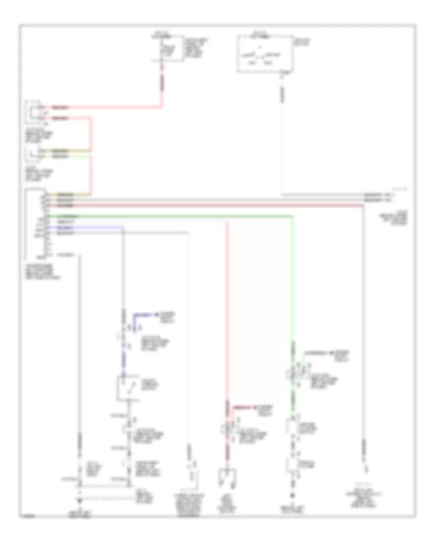
Diagram sections — 27 (44 total)
AIR CONDITIONING ANTI-LOCK BRAKES ANTI-THEFT BODY CONTROL MODULES COMPUTER DATA LINES COOLING FAN CRUISE CONTROL DEFOGGERS ELECTRONIC POWER STEERING ENGINE PERFORMANCE EXTERIOR LIGHTS GROUND DISTRIBUTION HEADLIGHTS HORN INSTRUMENT CLUSTER INTERIOR LIGHTS NAVIGATION PASSIVE RESTRAINTS POWER DISTRIBUTION POWER DOOR LOCKS POWER MIRRORS POWER WINDOWS RADIO SHIFT INTERLOCK SUPPLEMENTAL RESTRAINTS WARNING SYSTEMS WIPER/WASHER
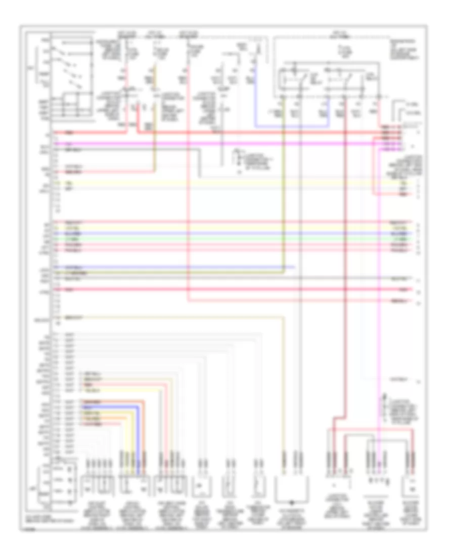
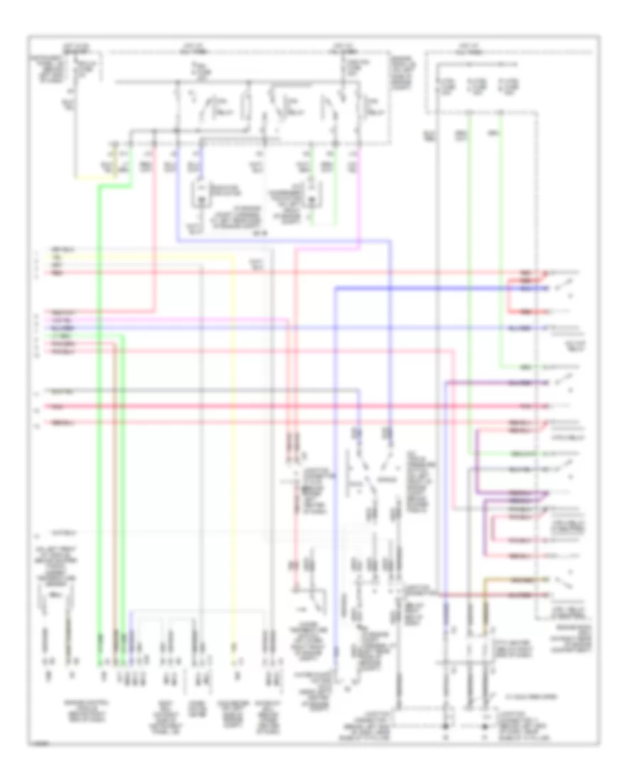
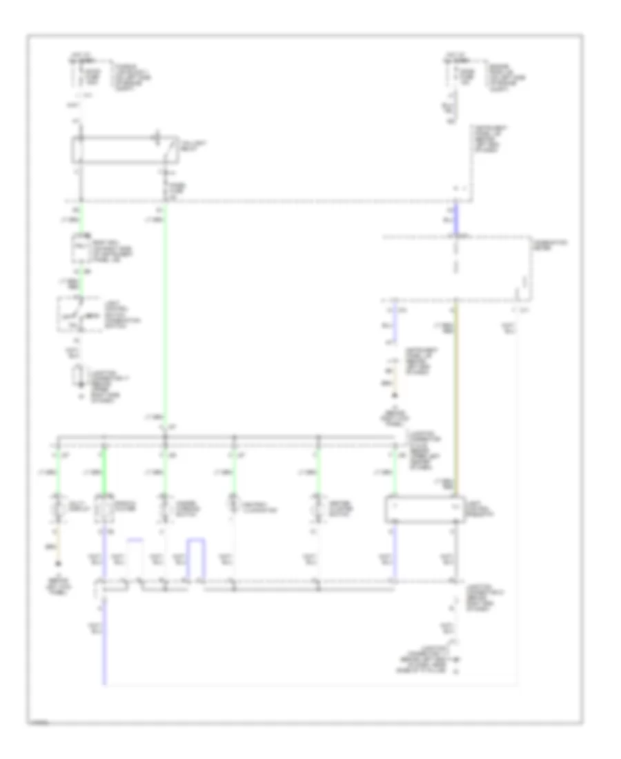
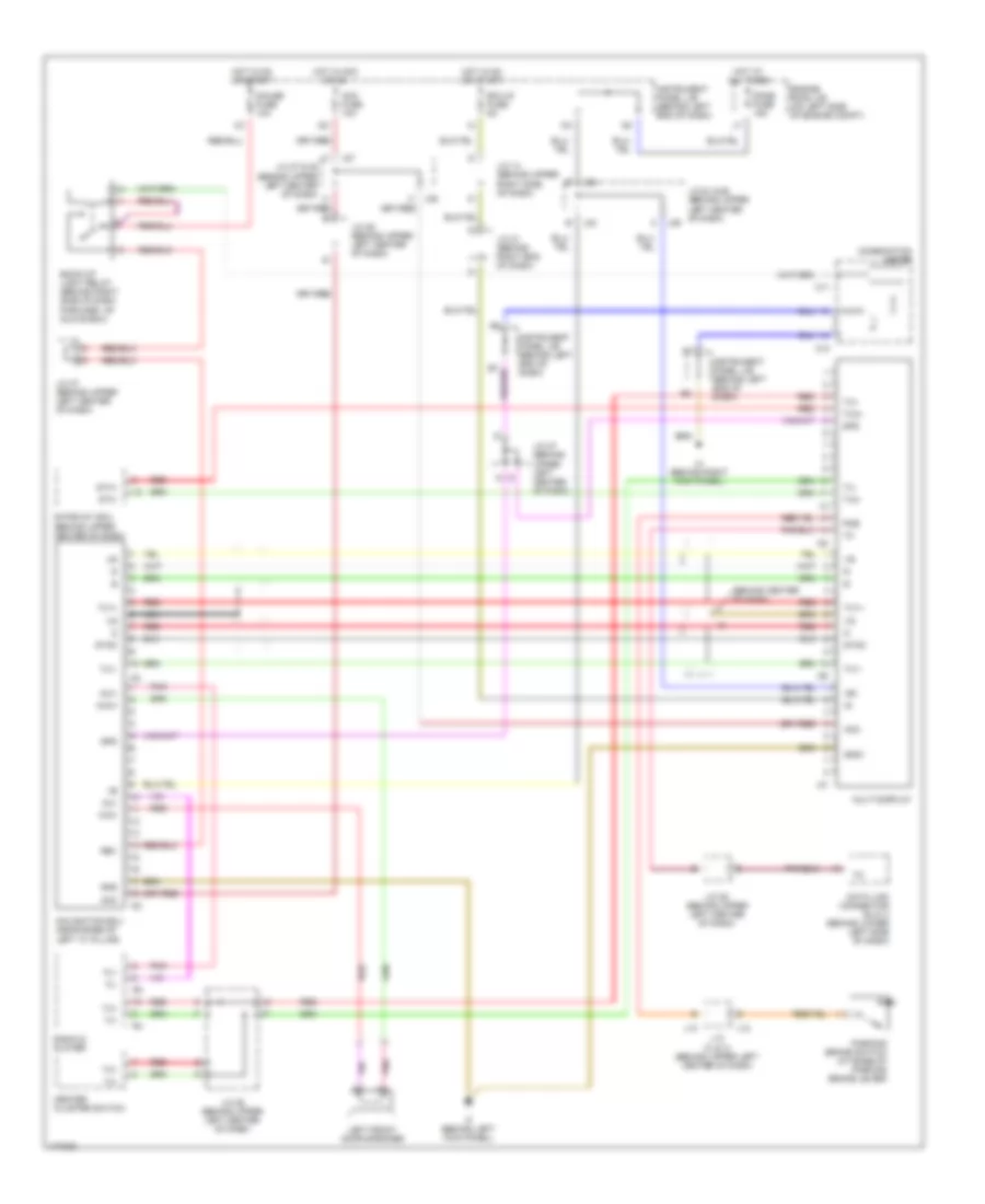
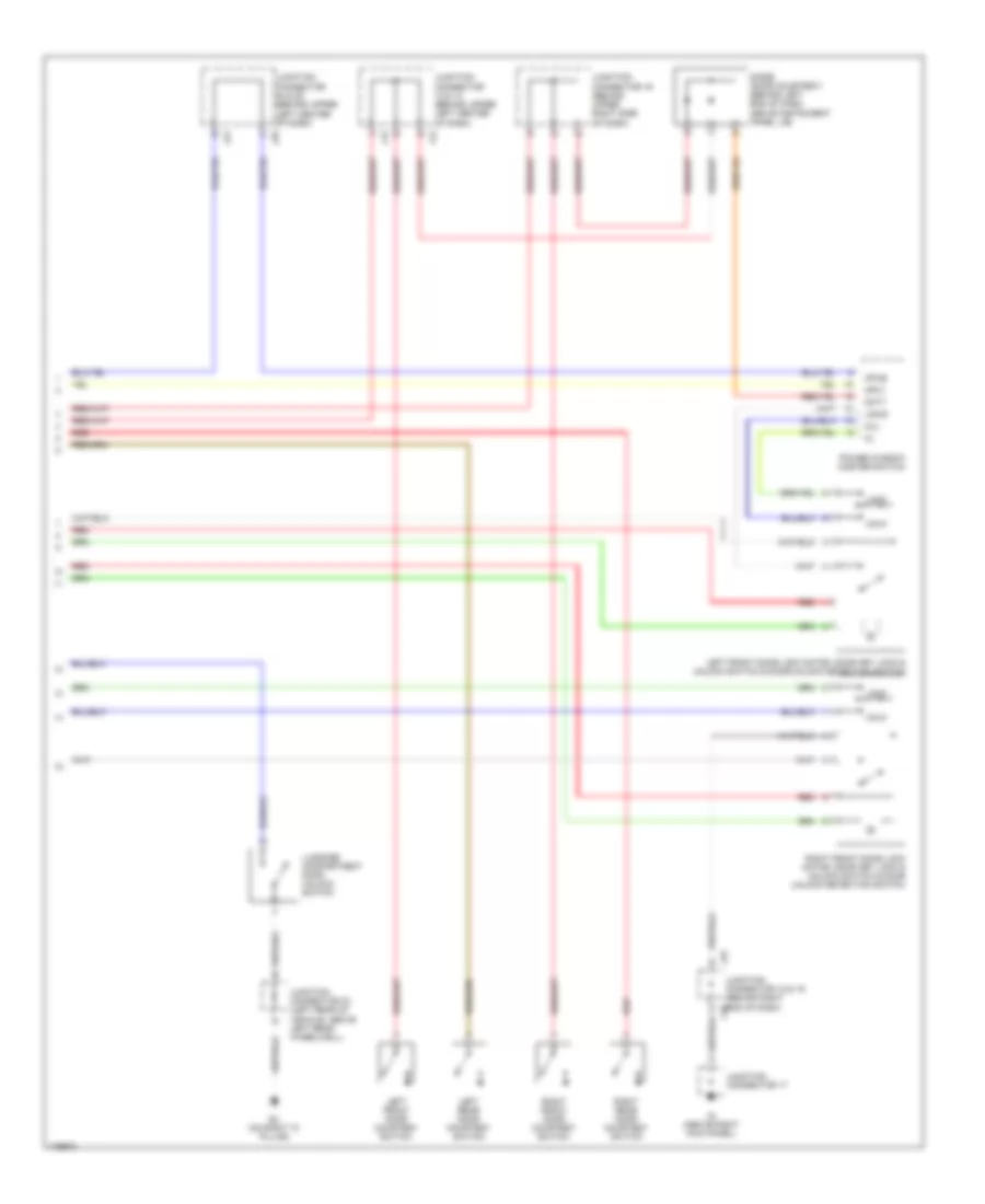
AIR CONDITIONING Automatic A/C Wiring Diagram (1 of 2) for Toyota Prius 2003 List of elements for Automatic A/C Wiring Diagram (1 of 2) for Toyota Prius 2003: 79 A j24 A j25 A/c A/c amplifier (behind center of dash) A/c magnetic clutch & lock sensor (on left front of engine) A/c room temperature sensor (behind left center of dash) A/c solar sensor (behind top right side of dash) A/c thermistor (behind lower center of dash) Act Aif Air Air inlet control servo motor (behind right side of dash, on hvac assembly) Air mix control servo motor (behind left center of dash, on hvac assembly) Air vent mode control servo motor (behind left center of dash, on hvac assembly) Amc Amh Aod Aof Blower motor (behind lower right side of dash) Blower motor linear controller (behind right center of dash) Blw Body ecu Bset C j22 Clr mg relay Ecu-b fuse 7.5a Engine room j/b (on left side of engine compartment) F/r Full a/c Gauge fuse 10a Gnd Hot at all times Hot in on or start Hrly Htr fuse 10a Htr fuse 50a Htr relay Htr2 Htro Idh Instrument panel j/b (behind left end of dash) J13 J22 J23 Junction connector (behind upper left center of dash) Junction connector 1 (behind left end of dash, near base of "a" pillar) Junction connector 11 (near base of "a" pillar) Junction connector 2 & 3 (behind upper left end of dash) Junction connector 22 & 23 (behind upper left side of dash) Junction connector 24 & 25 (behind upper left center of dash) Junction connector 6 (behind left end of dash, near base of "a' pillar) Led Lock Mgc Mp2+ Mpx+ Mset Pig Pig5 Pnk Psg Psw Rdef Red S5tp S5tpi S5tpm S5ts Sglock Sgte Sgtp Sgtpi Sgtpm Sgtr Tpi Tpm Tset W/ drl W/o drl Automatic A/C Wiring Diagram (2 of 2) for Toyota Prius 2003 List of elements for Automatic A/C Wiring Diagram (2 of 2) for Toyota Prius 2003: 56 (behind left end of dash, near base of "a" pillar) (in engine compt harness, at left rear side of engine compt) (on left front of vehicle, behind bumper fascia) ambient temperature sensor A/c condenser fan motor (on left front of engine compt) A/c triple pressure switch (on left front of engine compt, behind bumper fascia) A/c w/p relay A11 Act Body ecu (on right side of instrument panel j/b) C11 Cds fan fuse 30a Combi- nation meter Converter (on left side of engine compt) Dual E10 Ecu-ig fuse 5a Engine control module (behind right end of dash) Engine room j/b (on left side of engine compt) Engine room r/b 3 (on right rear of engine compartment) Fan Fan relay Gateway ecu (behind upper center of dash) Hot at all times Hot in on or start Htr 1 relay (if equipped) Htr 2 relay (if equipped) Htr 3 relay Htr1 fuse 30a Htr2 fuse 30a Htr3 fuse 50a Idh Instrument panel j/b (behind left end of dash) J10 J12 J27 Junction connector (below right end of dash) Junction connector 1 Junction connector 11 (behind left end of dash, near base of "a" pillar) Junction connector 27 & 28 (behind j28 upper left center of dash) Meo2 Mpd1 Mpd2 Mpx+ Mpx- Mpx1 Mpx2 Pnk Ptc heater (below right end of dash) Radiator fan motor Rdi fuse 30a Red Single Tam W/ cold area spec Water pump motor (a/c) (near left center of engine compt) Water temperature switch (on lower right front of engine compt)
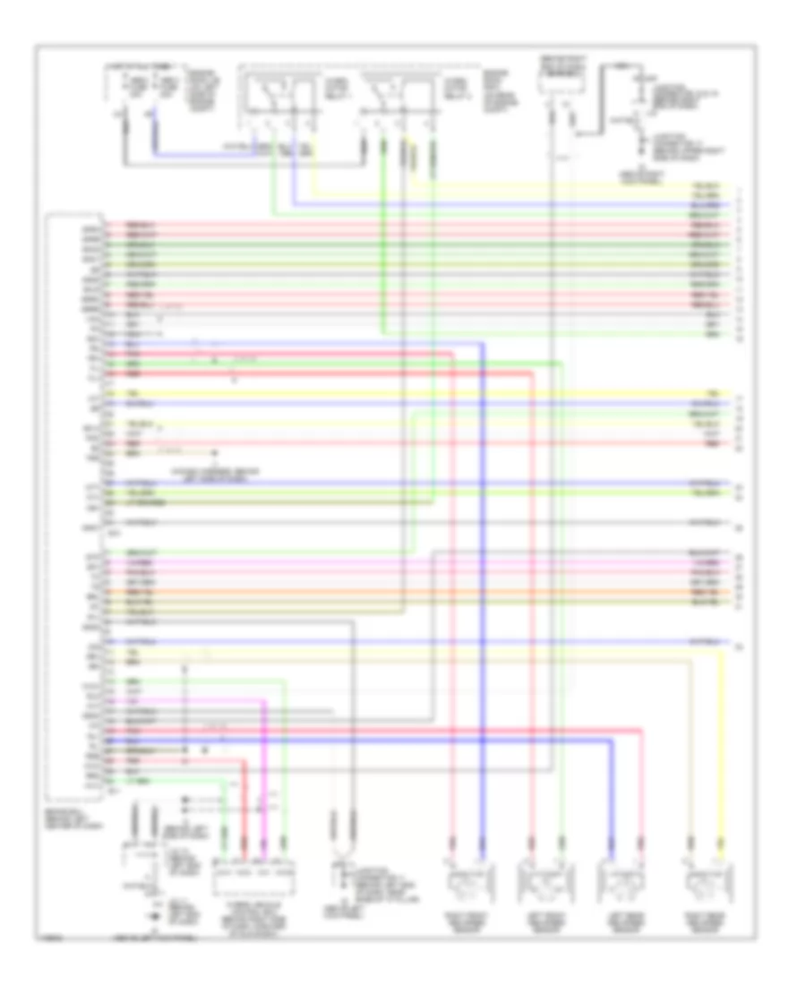
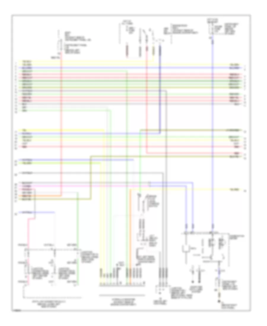
ANTI-LOCK BRAKES Anti-lock Brakes Wiring Diagram (1 of 3) for Toyota Prius 2003 List of elements for Anti-lock Brakes Wiring Diagram (1 of 3) for Toyota Prius 2003: 71 (behind right end of dash) emps ecu Abs 2 fuse 30a Abs 3 fuse 20a B10 B11 Brake ecu (behind left center of dash) Brl D/g Engine room j/b (on left side of engine compt) Engine room r/b 2 (on rear of engine compt) Fl+ Fl- Fr+ Fr- Fss Gnd1 Gnd2 Gnd3 Gnd4 Hot at all times Hvi+ Hvi- Hvo+ Hvo- Hybrid vehicle control ecu (behind right side of dash, forward of glove box) Hydro motor relay 1 Hydro motor relay 2 I1 (in dash harness, behind left side of dash) I3 (behind left side of dash) Id (above left kick panel) Ig (above right kick panel) Ig1 J/c 10 (behind left end of dash) J/c 11 (behind left end of dash) J18 J19 Junction connector 11 (behind left end of dash, near base of "a" pillar) Junction connector 17 (behind upper right side of dash) Junction connector 18 & 19 (behind right end of dash) Left front abs speed sensor Left rear abs speed sensor Mr1 Mt+ Mt- Mtt Nca Pmc Pnk R1+ Red Right front abs speed sensor Right rear abs speed sensor Rl+ Rl- Rlo Rr+ Rr- Rro Rss Sflh Sflr Sfrh Sfrr Sg1 Smc1 Smc2 Sp1 Srrh Srrr Stp Vcm Anti-lock Brakes Wiring Diagram (2 of 3) for Toyota Prius 2003 List of elements for Anti-lock Brakes Wiring Diagram (2 of 3) for Toyota Prius 2003: 29 (on right rear of engine compartment) Abs 1 fuse 40a Abs ind Abs sol relay Body ecu (on right side of instrument panel j/b) Brake fluid level warning switch Brake ind C10 C11 Combination meter Compartment) e5 Computer data lines system Data link connector (dlc) 3 (behind lower left side of dash) Engine room r/b 3 (on right rear of engine compartment) Gauge fuse 10a Hot at all times Hot in on Hydraulic booster Ie (above left kick panel) Ih (behind right kick panel) Instrument panel j/ b (behind left end of dash) Instrument panel j/b (behind left end of dash) J/c 7 (below right end of dash) Junction connector 1 (behind left end of dash, near base of "a" pillar) Junction connector 16 (behind upper right side of dash) Junction connector 22 (behind upper left side of dash) Junction connector 26 (behind upper left center of dash) Or start Red Anti-lock Brakes Wiring Diagram (3 of 3) for Toyota Prius 2003 List of elements for Anti-lock Brakes Wiring Diagram (3 of 3) for Toyota Prius 2003: 53 Abs 4 fuse 10a Acc All times Ast B12 B13 Brake actuator (on left rear of engine compt) Brake ecu (behind left center of dash) Brake warning buzzer (behind left side of dash) Bs+ Ecu-ig fuse 5a Efr Engine room r/b 3 (on right rear of engine compt) Ereg Err G12 Hot at Hot at all times Hot in on Ig2 Ignition switch Instrument panel j/b (behind left end of dash) J14 J15 Junction connector 12 (behind upper left center of dash) Junction connector 14 & 15 (behind upper right side of dash) Junction connector 14 (behind upper right side of dash) Lbl Lock Mr2 Nca Or start Parking brake switch (at base of parking brake lever) Pfr Pkb Pnk Preg Prr R2+ Red Sg2 Sg3 Sg4 Sla+ Sla- Slr+ Slr- Start Stop fuse 15a Stoplight switch (above brake pedal, on bracket) Vfr Vreg Vrr
ANTI-THEFT Forced Entry Wiring Diagram (1 of 2) for Toyota Prius 2003 List of elements for Forced Entry Wiring Diagram (1 of 2) for Toyota Prius 2003: 63 (behind upper left side of dash) j/c 22 & 23 Act+ Act- Actd Bdr Bi (on left ``c" pillar) Bj (on right ``c" pillar) Body ecu Dcty Dome fuse 15a Door fuse 30a Ecu-b fuse 7.5a Engine hood courtesy switch (near hood latch) Engine room j/b (on left side of engine compt) Gauge fuse 10a Hcty Horns system Hot at all times Hot in on or start Id (above left kick panel) Ie (above left kick panel) Ig (above right kick panel) Immobilizer circuit Ind Instrument panel j/b (behind left end of dash) J/c 1 (behind left end of dash) J/c 11 (behind left end of dash) J/c 14 & 15 (behind upper right side of dash) J/c 17 (behind upper right side of dash) J/c 18 & 19 (behind right end of dash) J/c 24 & 25 (behind upper left center of dash) J/c 26 (behind upper left center of dash) J/c 27 & 28 (behind j28 J/c 27 (behind upper left center of dash) J/c 33 (above left rear wheelwell) J14 J15 J18 J19 J22 J23 J24 J25 J27 Ksw Left rear door lock motor & door unlock detection switch Lock Lsr Lswp Lug Luggage compartment door key unlock switch Obdii fuse 7.5a Pcty Rcty Red Right front door lock control switch Right rear door lock motor & door unlock detection switch Theft deterrent horn (behind right headlight) Ul1 Ul2 Unlk Unlock warning switch Upper left center of dash) Forced Entry Wiring Diagram (2 of 2) for Toyota Prius 2003 List of elements for Forced Entry Wiring Diagram (2 of 2) for Toyota Prius 2003: 38 Center cluster switch Cpub Dcty Diode (door courtesy) (behind left end of dash, above instrument panel j/b) Id (behind left kick panel) If (behind left kick panel) Ig (above right kick panel) Immobilizer circuit Instrument panel j/b (behind left end of dash) J/c 11 (behind left end of dash) J/c 12, j/c 13 (behind upper left center of dash) J/c 16 (behind upper right side of dash) J/c 17 (behind upper right side of dash) J/c 18, j/c 19 (behind right end of dash) j18 J/c 24 (behind upper left center of dash) J/c 24, j/c 25 (behind upper left center of dash) J/c 27, j/c 28 (behind upper left center of dash) J12 J13 J19 J24 J25 J27 J28 Kul Left front door courtesy switch Left front door lock motor, door key lock & unlock switch & door unlock detection switch Left rear door courtesy switch Lock Lswd Mpx1 Power window master switch Radio & player Red Right front door courtesy switch Right front door lock motor, door key lock & unlock switch & door unlock detection switch Right rear door courtesy switch Unlk Immobilizer Wiring Diagram for Toyota Prius 2003 List of elements for Immobilizer Wiring Diagram for Toyota Prius 2003: 40 Acc Center cluster switch Cty Data link connector (dlc) 3 (behind lower left side of dash) Ecu-b fuse 7.5a Fcvc Forced entry circuit Gnd H14 Hevc Hot at all times Hybrid vehicle control ecu (behind right side of dash, forward of glove box) Id (above left kick panel) If (behind left kick panel) Ig2 Ignition switch Ind Instrument panel j/b (behind left end of dash) J/c 10 (on left end of dash) J/c 11 (behind left end of dash) J/c 12 & 13 (behind upper left center of dash) J/c 20 (behind upper left center of dash) J/c 24 & 25 (behind upper left center of dash) J/c 24 (behind upper left center of dash) J/c 27 & 28 (behind upper left center of dash) J12 J13 J24 J25 J27 J28 Ksw Left front door courtesy switch Lock Op1 Radio & player Run Start Transponder key computer (behind upper left side of dash) Unlock warning switch
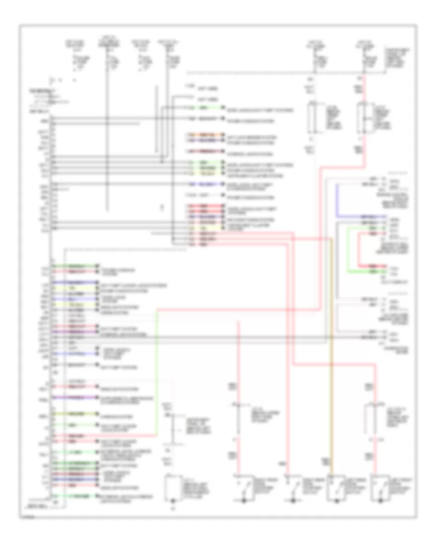
BODY CONTROL MODULES Body Control Modules Wiring Diagram for Toyota Prius 2003 List of elements for Body Control Modules Wiring Diagram for Toyota Prius 2003: 97 (not used) A/c amplifier (behind center of dash) Acc fuse 10a Act+ Act- Actd Air conditioning system Anti-lock brakes system Anti-theft & door locks system Anti-theft & door locks systems Anti-theft system Bdr Body ecu C11 Combination meter Dbkl Dcty Def relay Dfg Door fuse 30a Door locks & anti-theft systems Door locks system Door locks, anti-theft & warning systems E10 Ecu-b fuse 7.5a Engine control module (behind right end of dash) Exterior lights & interior lights systems Exterior lights, interior lights, headlights & warning systems Fld Flu Fu+ Fu- Fua Gateway ecu (behind upper center of dash) Gauge fuse 10a Gtx+ Gtx- Hcty Headlights system Horns system Hot at all times Hot in on or start Hot in on or acc Hot w/ tail relay energised Hrly Ind Instrument cluster system Instrument panel j/b (behind left end of dash) Interior lights system J/c 11 (behind left end of dash, near base of "a" pillar) J/c 12 & 13 (behind upper left center of dash) J/c 16 (behind upper right side of dash) J/c 26 (behind upper left center of dash) J/c 27 (behind upper left center of dash) J10 J12 J13 Ksw Lcty Left front door courtesy switch Left rear door courtesy switch Lsr Lswp Lug Mp2+ Mpd1 Mpd2 Mpx+ Mpx- Mpx1 Mpx2 Multi display Obd ii fuse 7.5a Pcty Pkb Pkbl Power relay Power windows system Prg Rcty Rda Rdy Red Right front door courtesy switch Right rear door courtesy switch Rld Rlu Rrd Rru Tail Tail fuse 7.5a Trly Tx3+ Tx3- Ul1 Ul2 Warning system
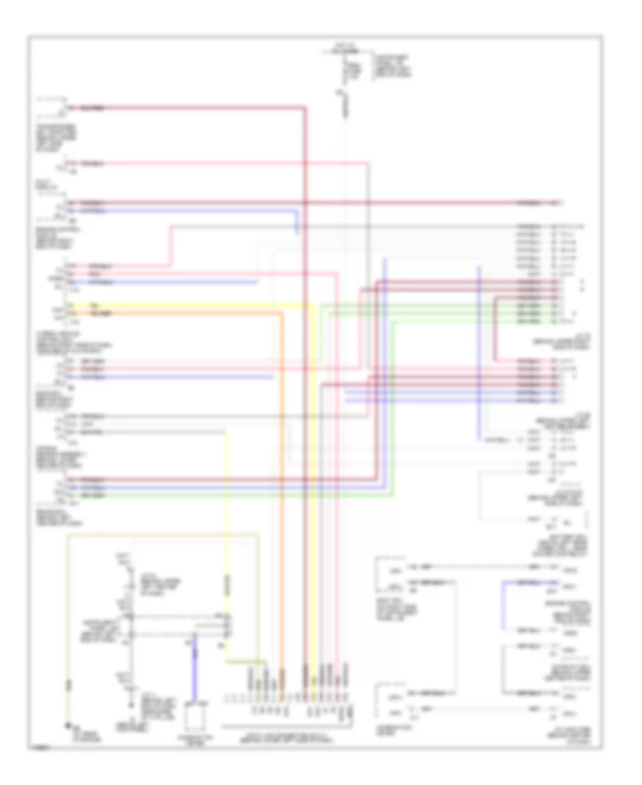
COMPUTER DATA LINES Computer Data Lines Wiring Diagram for Toyota Prius 2003 List of elements for Computer Data Lines Wiring Diagram for Toyota Prius 2003: 50 A/c amplifier (behind center of dash) A18 Air bag sensor assembly (behind lower center of dash) B11 B17 Bat Battery ecu (above left rear wheelwell, near system main relay) Body ecu (on right side of instrument panel j/b) Brake ecu (behind left center of dash) C10 C11 Combination meter D/g Data link connector (dlc) 3 (behind lower left side of dash) E10 Eb (at rear of engine) Emps ecu (behind right end of dash) Engine control module (behind right end of dash) Gateway ecu (behind upper center of dash) H13 H14 Hai Hao Hot at all times Hybrid vehicle control ecu (behind right side of dash, forward of glove box) Id (above left kick panel) Instrument panel j/b (behind left end of dash) J/c 11 (behind left end of dash, near base of 'a' pillar) J/c 16 (behind upper right side of dash) J/c 22 & 23 (behind upper left side of dash) J/c 24 (behind upper left center of dash) J/c 26 (behind upper left center of dash) J22 J23 Mp2+ Mpd1 Mpd2 Mpx+ Mpx- Mpx1 Mpx2 Multi display Obdii fuse 7.5a Op1 Op2 Op3 Pnk Sil Transponder key computer (behind upper left side of dash) Wfse
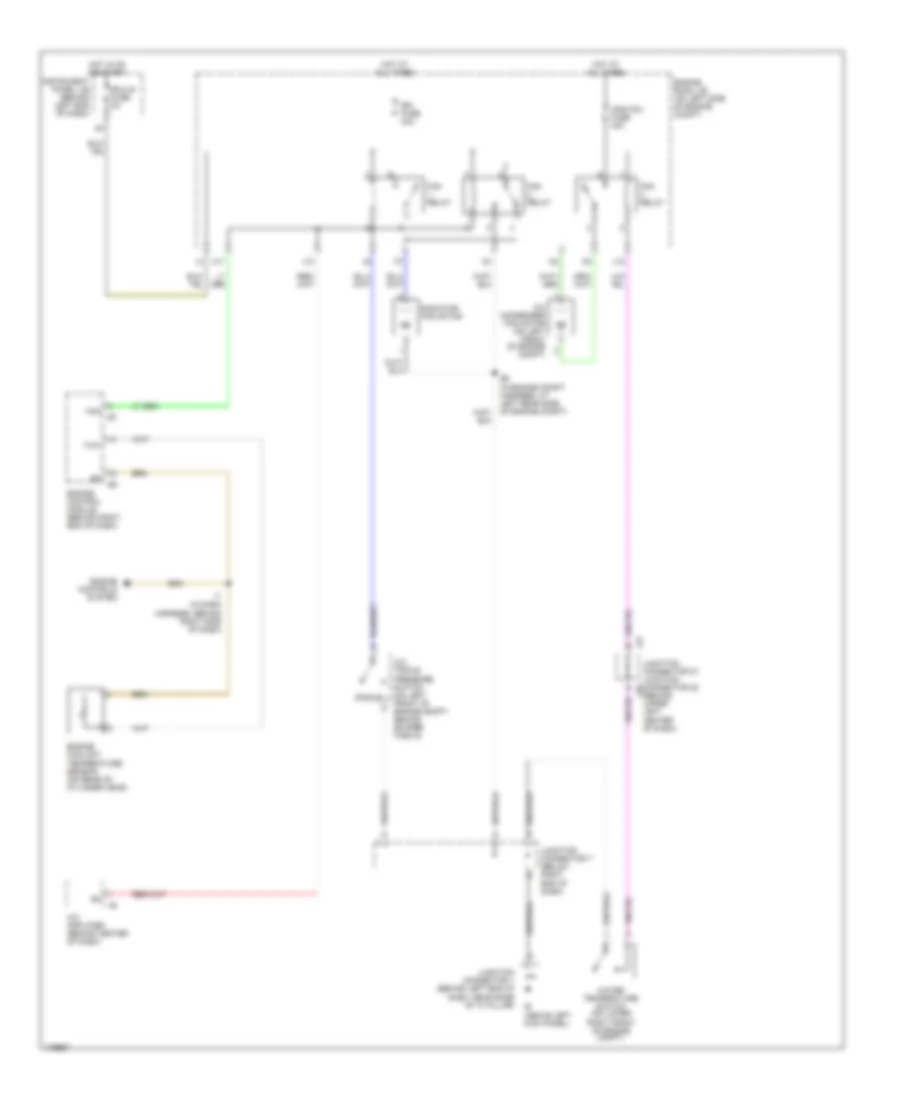
COOLING FAN Cooling Fan Wiring Diagram for Toyota Prius 2003 List of elements for Cooling Fan Wiring Diagram for Toyota Prius 2003: 29 (behind upper left center of dash) A/c amplifier (behind center of dash) A/c condenser fan motor (on left front of engine compt) A/c triple pressure switch (on left front of engine compt, behind bumper fascia) A11 Cds fan fuse 30a Ecu-ig fuse 5a Engine control module (behind right end of dash) Engine controls system Engine coolant temperature sensor (on rear of cylinder head) Engine room j/b (on left side of engine compt) Fan Fan relay Hot at all times Hot in on or start I7 (in dash harness, behind right side of dash) Ie (above left kick panel) Instrument panel j/b (behind left end of dash) J10 J12 J27 Junction connector 1 (behind left end of dash, near base of "a" pillar) Junction connector 27, junction connector 28 j28 Junction connector 7 (below right end of dash) Radiator fan motor Rdi fuse 30a Single Thw Water temperature switch (on lower right front of engine compt)
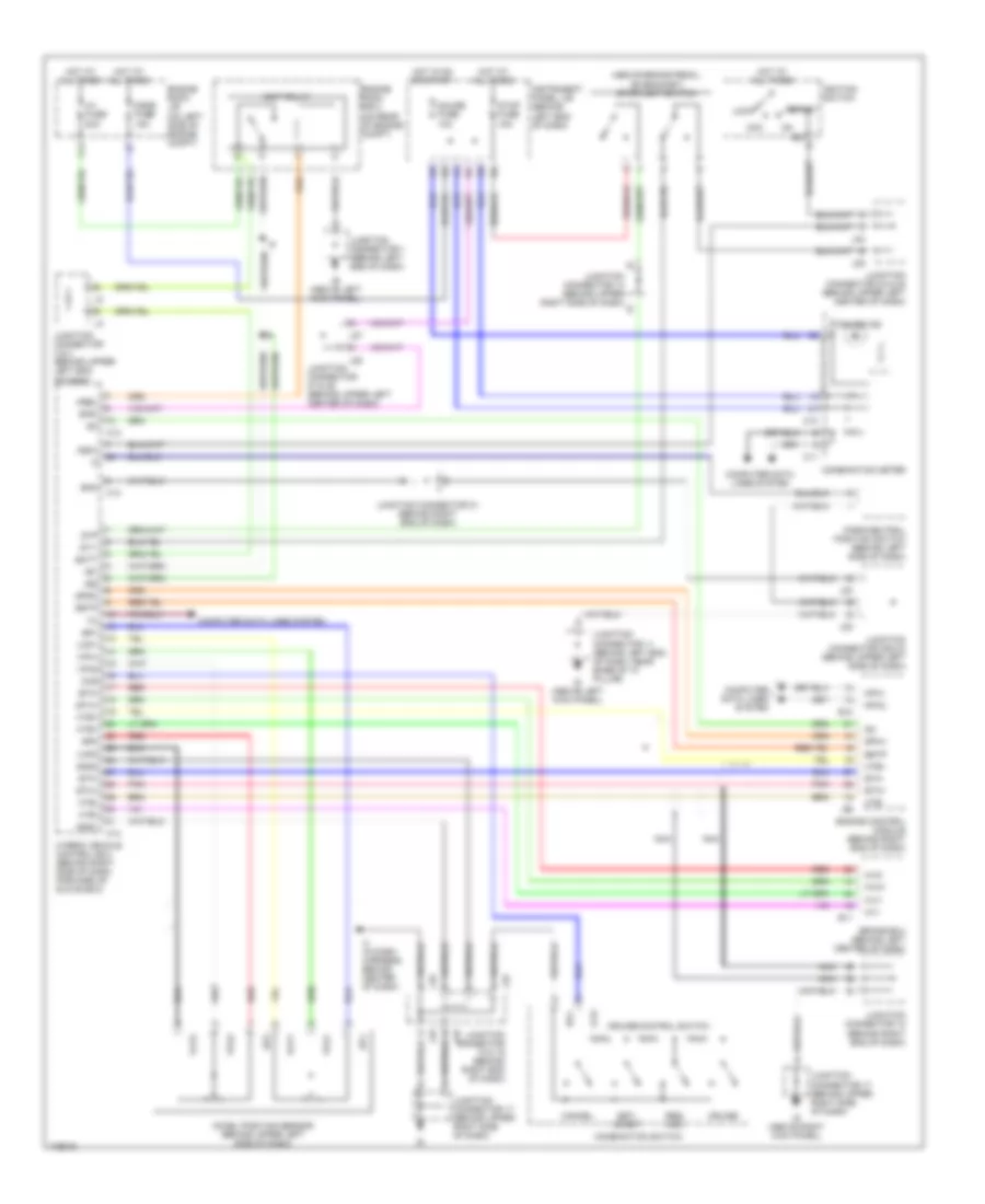
CRUISE CONTROL Cruise Control Wiring Diagram for Toyota Prius 2003 List of elements for Cruise Control Wiring Diagram for Toyota Prius 2003: 100 (above brake pedal, on bracket) stoplight switch +b1 +b2 Acc Accel position sensor (behind upper left side of dash) B11 Batt Brake ecu (behind left center of dash) Bth+ Bth- C10 C11 Cancel Ccs Combination meter Combination switch Computer data lines system Cruise Cruise control switch Cruise ind Dome fuse 15a E10 Ecc Engine control module (behind right end of dash) Engine room j/b (on left side of engine compt) Engine room r/b 2 (on rear of engine compt) Eom Ep1 Ep2 Estp Eth+ Eth- F11 Gauge fuse 10a Gnd1 Gnd2 H12 H13 H14 Hot at all times Hot in on or start Htb+ Htb- Hte+ Hte- Hv fuse 20a Hvi+ Hvi- Hvo+ Hvo- Hybrid vehicle control ecu (behind right side of dash, forward of glove box) I4 (in dash harness, behind center of dash) Id (above left kick panel) Ie (above left kick panel) Ig (above right kick panel) Ig2 Igct relay Ignition switch Igsw Instrument panel j/b (behind left end of dash) J18 J19 J22 J23 J24 J25 J27 J28 Junction connector 1 (behind left end of dash) Junction connector 11 (behind left end of dash, near base of "a" pillar) Junction connector 14 (behind upper right side of dash) Junction connector 17 (behind upper right side of dash) Junction connector 18 & 19 (behind right end of dash) Junction connector 18 (behind right end of dash) Junction connector 2 & 3 (behind upper left end of dash) Junction connector 21 (behind right end of dash) Junction connector 22& 23 (behind upper left side of dash) Junction connector 24 & 25 (behind upper left center of dash) Junction connector 27 & 28 (behind upper left center of dash) Lock Mpx1 Mpx2 Mrel Nca Park/neutral position switch (behind left side of dash) Pnk Red Res/ acc Set/ coast Spdi Spdo Sphv St1- Start Stop fuse 15a Stp Vcp1 Vcp2 Vpa1 Vpa2
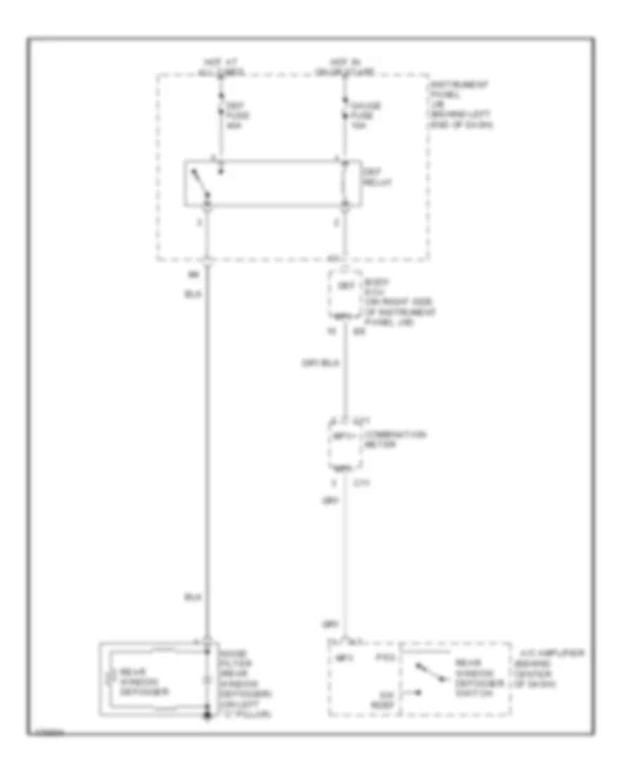
DEFOGGERS Defoggers Wiring Diagram for Toyota Prius 2003 List of elements for Defoggers Wiring Diagram for Toyota Prius 2003: 20 (behind center of dash) A/c amplifier Body ecu (on right side of instrument panel j/b) C11 Combination meter Def Def fuse 40a Def relay Gauge fuse 10a Hot at all times Hot in on or start Instrument panel j/b (behind left end of dash) Mpx Mpx+ Mpx- Noise filter (rear window defogger) (on left ``c" pillar) Psg Rear window defogger Rear window defogger switch Sw rdef
ELECTRONIC POWER STEERING Electronic Power Steering Wiring Diagram for Toyota Prius 2003 List of elements for Electronic Power Steering Wiring Diagram for Toyota Prius 2003: 45 B11 Brake ecu (behind left center of dash) C10 Combination meter Data link connector (dlc) 3 (behind lower left side of dash) Dc motor (on center rear of engine compt) Ecu-b fuse 7.5a Ecu-ig fuse 5a Emps ecu (behind right end of dash) Emps fuse 50a Emps relay Engine room r/b 3 (on right rear of engine compt) Gnd Hot at all times Hot in on or start I7 (in dash harness, behind right side of dash) Instrument panel j/b (behind left end of dash) J/c 14 & 15 (behind upper right side of dash) J/c 16 (behind upper right side of dash) J/c 17 (behind upper right side of dash) J/c 18 & 19 (behind right end of dash) J/c 22 (behind upper left side of dash) J/c 26 (behind upper left center of dash) J14 J15 J18 J19 Nca Pgnd Pig Red Rlo Rly Rro Sil Steering shaft torque sensor (on rear of engine compt) Trq1 Trq2 Trqg Trqv Vcc Vt1 Vt2 Wrl Wrr
ENGINE PERFORMANCE Hybrid System Wiring Diagram (2 of 3) for Toyota Prius 2003 List of elements for Hybrid System Wiring Diagram (2 of 3) for Toyota Prius 2003: 46 (above left rear wheelwell) hybrid vehicle battery (left center of dash) j/c 24, j/c 25 (left side of luggage compt) battery blower motor controller (right side of dash) Acc Am2 fuse 15a B17 B18 Batt fan fuse 10a Battery blower motor (left side of luggage compt) Battery ecu (above left rear wheelwell) Battery fan relay (behind left taillight) Bi (left "c" pillar) Bj (right "c" Busbar module Engine room j/b (left side of engine compt) F11 G11 H16 H17 Hot at all times Hv fuse 20a Hybrid battery Ig2 relay Ignition switch Instrument panel j/b (left end of dash) J/c 11 (left end of dash) J/c 32, j/c 33 (above left rear wheelwell) J24 J25 J32 J33 Lock Pillar) Pnk Red S10 S11 S12 Sensor Service plug Start Stop fuse 15a Stop light switch System main relay (left rear wheelwell) Water pump motor (inverter) (below left headlamp) Hybrid System Wiring Diagram (3 of 3) for Toyota Prius 2003 List of elements for Hybrid System Wiring Diagram (3 of 3) for Toyota Prius 2003: 97 (behind left side of dash) park/neutral position switch (left center of dash) j/c 24, j/c 25 (left end of dash) j/c 2, j/c 3 (left rear of engine compt) converter (left rear wheelwell) (left side of dash) j/c 22, j/c 23 (right side of dash) +b1 +b2 A j19 A/c amplifier Abfs Accelerator position sensor (behind upper Air bag sensor assembly Amd Batt Brake ecu (behind center of dash) Bth+ Bth- Ccs Computer data lines system Con3 Cruise control system Data link connector 3 (behind lower left side of dash) Dc/dc fuse 100a Dc/dc-s fuse 5a Dth+ Dth- E10 Engine control module (right end of dash) Eom Ep1 Ep2 Estp Eth+ Eth- Fcvc Fusible link block 1 (left side of engine compt) Fusible link block 2 (behind left rear wheelwell) Gnd1 Gnd2 Gsft H13 H14 Hai Hao Hot at all times Htb+ Htb- Htd+ Htd- Hte+ Hte- Hybrid vehicle control ecu (behind right side of dash, forward of glove box) Idh Igct Igsw Ilk Interlock switch J/c 16 (right side of dash) J/c 17 (right side of dash) J/c 18, j/c 19 (right end of dash) J/c 21 (right end of dash) J/c 22, j/c 23 (left side of dash) J/c 26 (left center of dash) J18 J19 J22 J23 J24 J25 Left side of dash) Mcs Mcsg Mmt Mrf Mrfg Msn Msng Nca Nmtg Nodd Pnk Red Sft Sil Spdo St- St2 Stp Transponder key computer (upper left side of dash) Vcp1 Vcp2 Vpa1 Vpa2 Vsft Wfse
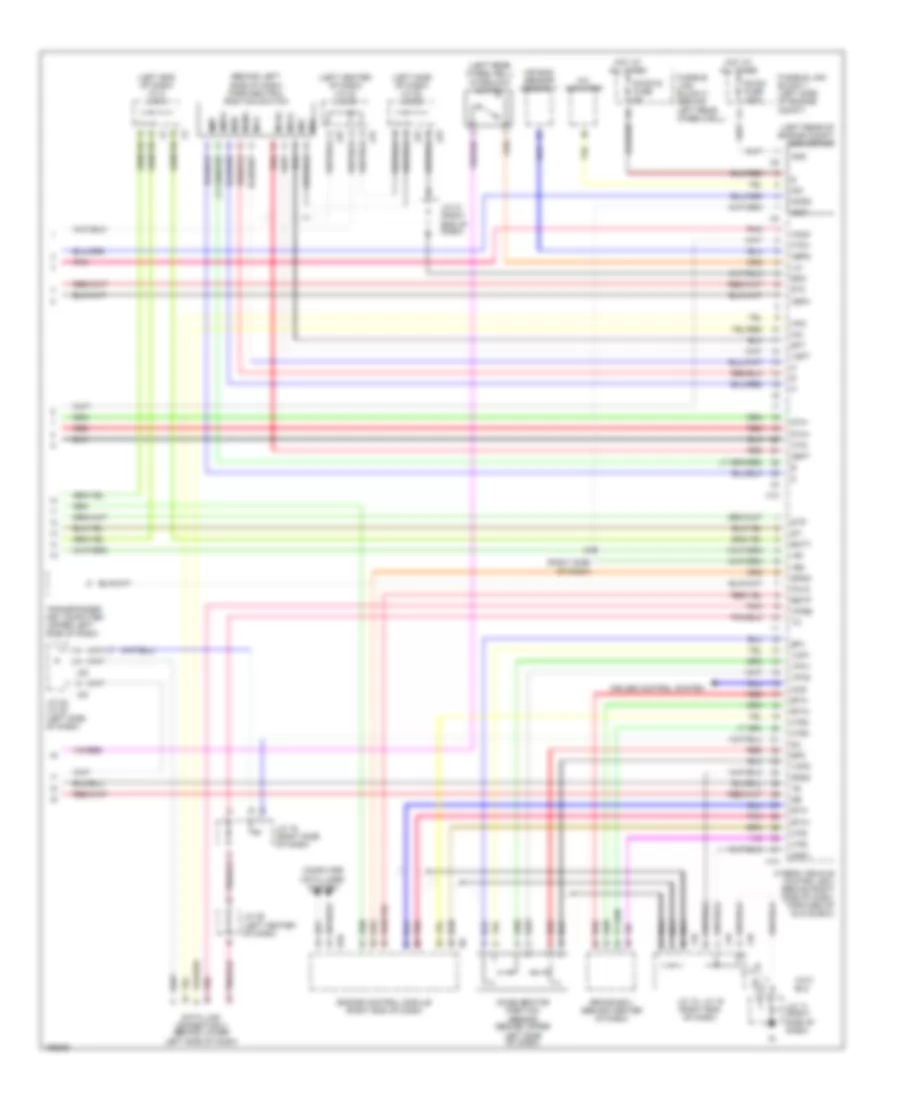
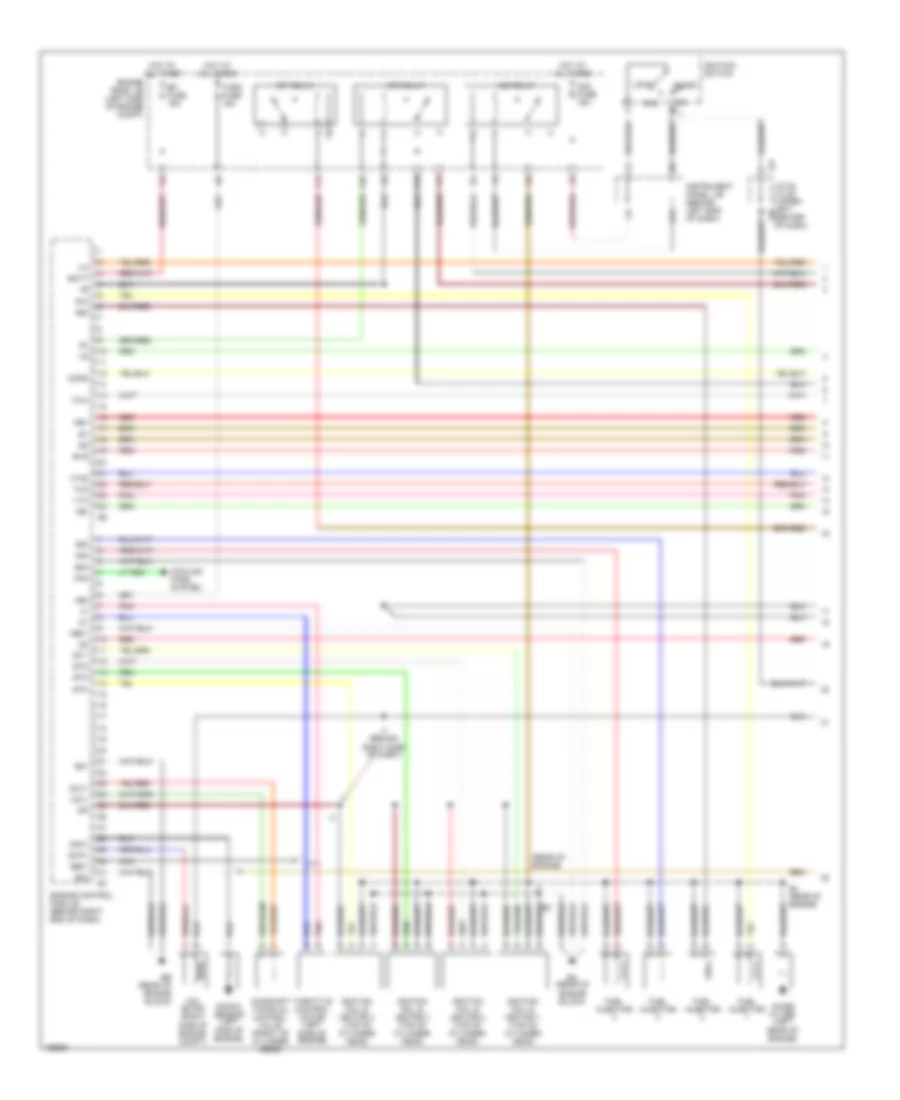
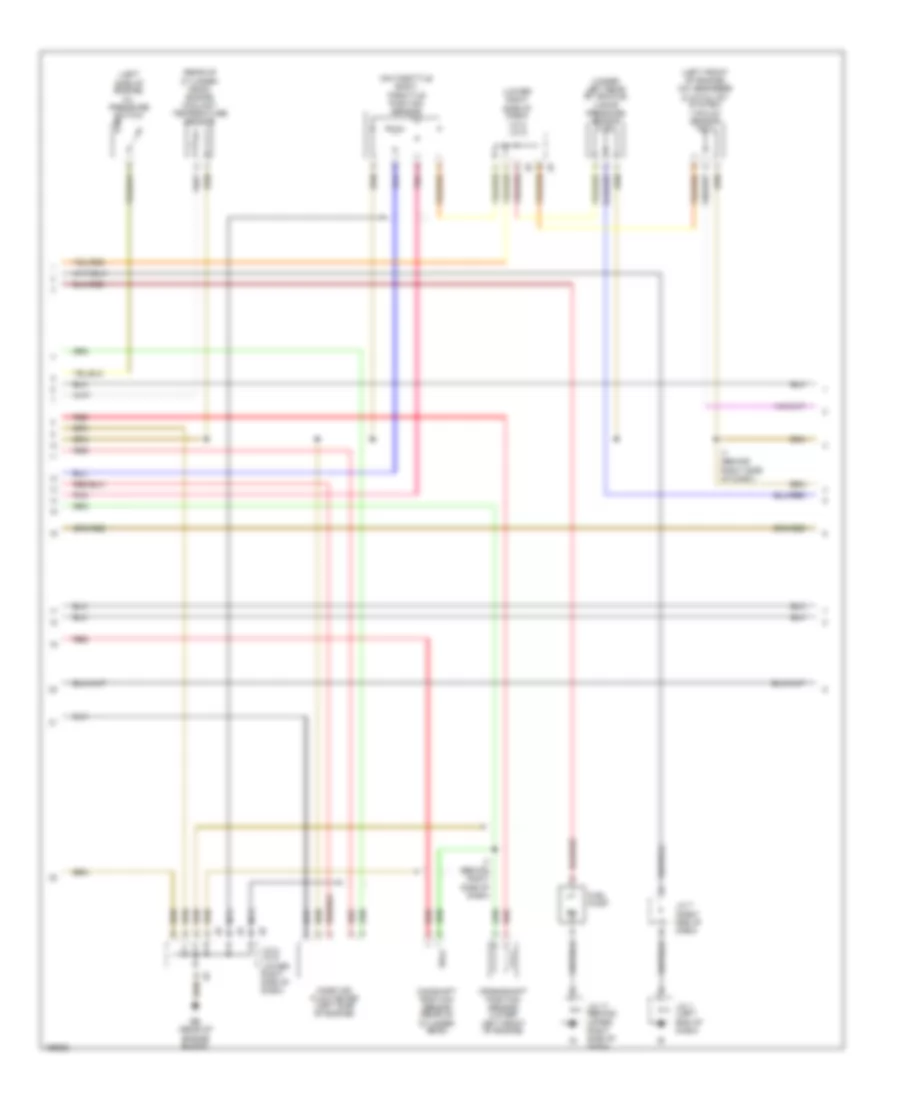
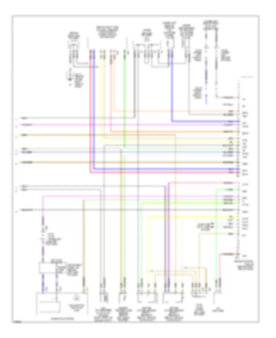
1.5L 1.5L, Engine Controls Wiring Diagram (1 of 3) for Toyota Prius 2003 List of elements for 1.5L, Engine Controls Wiring Diagram (1 of 3) for Toyota Prius 2003: 69 #10 #20 #30 #40 (rear of engine) +bm A10 Acc Am2 fuse 15a Batt Camshaft timing oil control valve (front of cylinder head) Cir relay Cooling fans system E01 E02 E03 E4 (rear of engine) Ea (rear of engine block) Eb (rear of engine block) Efi fuse 15a Efi relay Engine control module (behind right end of dash) Engine room j/b (left side of engine compt) Evg Evp1 F12 F13 Fan Fuel injector G11 Ge01 Hot at all times I7 (behind right side of dash) Ig2 relay Igf Ignition coil & ignitor 1 (top of cylinder head) Ignition coil & ignitor 2 (top of cylinder head) Ignition coil & ignitor 3 (top of cylinder head) Ignition coil & ignitor 4 (top of cylinder head) Ignition switch Igt1 Igt2 Igt3 Igt4 Instrument panel j/b (behind left end of dash) J/c 24, j/c 25 (upper left j25 center of dash) J24 Knk1 Knock sensor (left side of engine) Lock Me01 Mops Nca Ne+ Ne- Noise filter (left rear of engine) Ocv+ Ocv- Pnk Red Side of engine) Start Tha Thro fuse 15a Throttle control motor (left Thw Vsv (evap) (right side of engine compt) Vta Vta2 1.5L, Engine Controls Wiring Diagram (2 of 3) for Toyota Prius 2003 List of elements for 1.5L, Engine Controls Wiring Diagram (2 of 3) for Toyota Prius 2003: 19 (left front of engine) (hc absorber & catalyst system) vacuum sensor (left side of engine) oil pressure switch (lower right side of dash) j/c 8, j/c 9 (on throttle body) throttle position sensor (rear of cylinder head) engine coolant temperature sensor (under left rear of vehicle) vapor pressure sensor Camshaft position sensor (rear of cylinder head) Crankshaft position sensor (lower left front of engine) Eb (rear of engine block) Fuel pump I7 (behind right side of dash) J/c 1 (left end of dash) J/c 17 (behind upper right side of dash) J/c 7 (right end of dash) J/c 8, j/c 9 (lower right side of dash) Mass air flow meter (left side of engine) Nca Pnk Red 1.5L, Engine Controls Wiring Diagram (3 of 3) for Toyota Prius 2003 List of elements for 1.5L, Engine Controls Wiring Diagram (3 of 3) for Toyota Prius 2003: 60 (behind right end of dash) j/c 18 (behind right side of dash, forward of glove box) hybrid vehicle control ecu (lower left side of dash) data link connector 3 (under center rear of vehicle) vsv (purge switching valve) (under left rear of vehicle) vsv (canister closed valve) (upper A/c amplifier Act Ambient temperature sensor (behind C10 C11 Ccv Combination meter Computer data lines system E10 E11 Engine control module (behind right end of dash) Estp Eth+ Eth- Gauge fuse 15a H12 H14 Hcc Hcls Heated oxygen sensor (bank 1, sensor 2) (below vehicle, on exhaust) Hot in on or start Ht1a Ht1b Hte- Igsw Instrument panel j/b (behind left end of dash) J/c 16 (upper right side of dash) J/c 17 (behind upper right side of dash) J/c 22 (upper left side of dash) J/c 22, j/c 23 (upper J/c 26 (upper left center of dash) J/c 27, j/c 28 (upper left center j27 of dash) J22 J23 J28 Left end of dash) j/c 4, j/c 5 Left front bumper) Left side of dash) Malfunction indicator lamp Mpx1 Mpx2 Mrel Nca Neo Ox1a Ox1b Pnk Ptnk Sil Spd Sphv Tam Tbp Vsv (hc absorber & catalyst system (right front of engine compt)
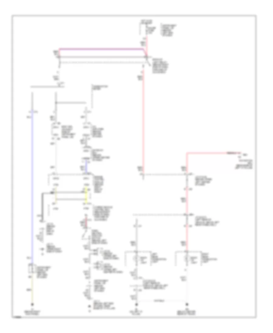
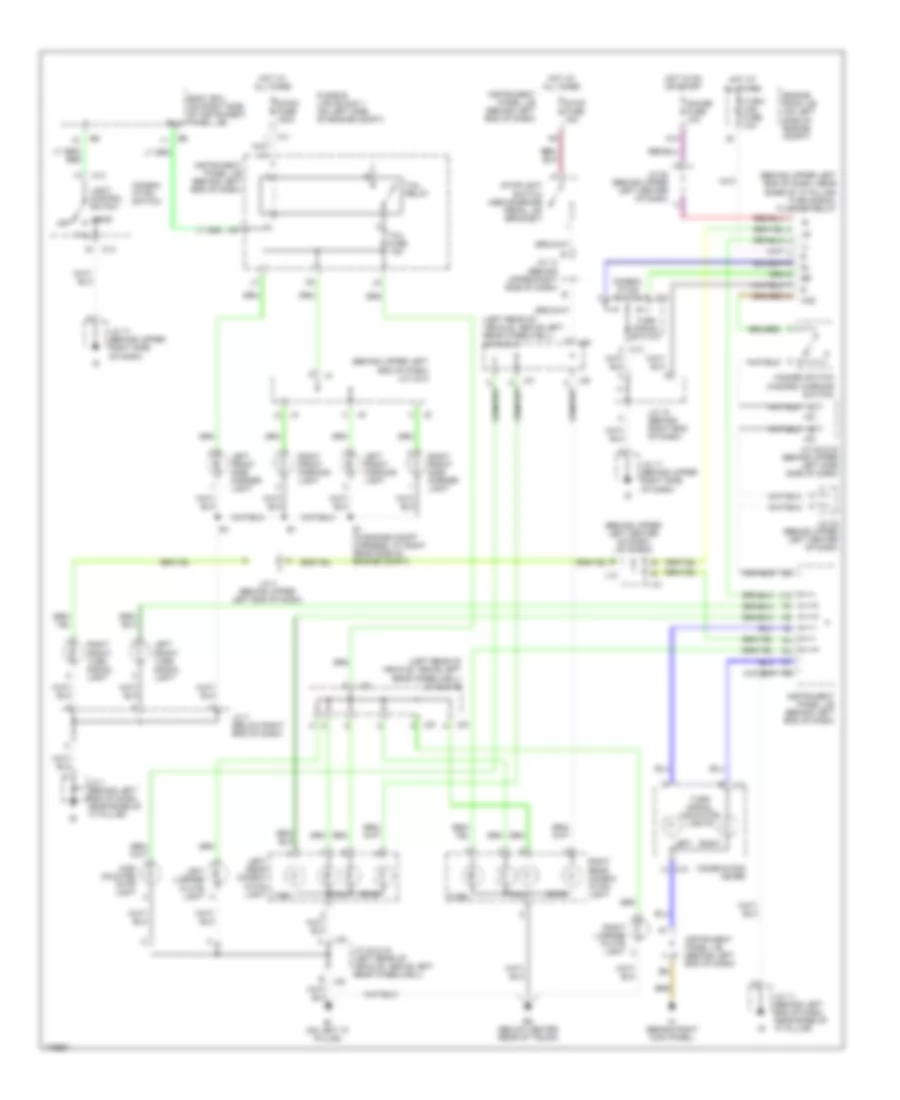
EXTERIOR LIGHTS Back-up Lamps Wiring Diagram for Toyota Prius 2003 List of elements for Back-up Lamps Wiring Diagram for Toyota Prius 2003: 48 A/c amplifier (behind center of dash) B j32 Back- up light Back-up light relay (behind right side of dash, forward of glove box) Bi (on left "c" pillar) Bk (below center rear of trunk) Body ecu (on right side of instrument panel j/b) C10 C11 Combination meter E10 Engine control module (behind right end of dash) Gateway ecu (behind upper center of dash) Gauge fuse 10a H14 Hot in on or start Hte+ Hte- Hybrid vehicle control ecu (behind right side of dash, forward of glove box) Ih (behind right kick panel) Instrument panel j/b (behind left end of dash) J/c 11 (behind left end of dash, near base of "a" pillar) J/c 17 (behind upper right side of dash) J/c 18 (behind right end of dash) J/c 22 (behind upper left side of dash) J/c 24 (behind upper left center of dash) J/c 27 & 28 (behind upper left center of dash) J/c 30 & 31 (left rear of vehicle, above left rear wheelwell) J/c 32 & 33 (left rear of vehicle, above left rear wheelwell) J27 d J28 b J30 J30 b J31 b J33 Left rear combination light Mpd1 Mpd2 Mpx+ Mpx- Mpx1 Mpx2 Mpx2+ Navigation ecu (near base of left "c" pillar) Nca Park/ neutral position switch (behind left side of dash) Rev Right rear combination light Exterior Lamps Wiring Diagram for Toyota Prius 2003 List of elements for Exterior Lamps Wiring Diagram for Toyota Prius 2003: 74 (behind upper left center of dash) j/c 12 & 13 (behind upper left end of dash) j/c 4 & 5 (behind upper left end of dash, near base of "a" pillar) turn signal flasher relay (left rear of vehicle, above left rear wheelwell) j/c 30 & 31 (left rear of vehicle, above left rear wheelwell) j/c 32 & 33 B j32 Bi (on left "c" pillar) Bk (below center rear of trunk) Body ecu (on right side of instrument panel j/b) C10 C13 Combin- ation switch Combination meter Dc/dc fuse 100a E1 (in engine compt harness, at right rear side of engine compt) Engine room j/b (on left side of engine compt) F11 Fusible link block 1 (on left side of engine compt) Gauge fuse 10a Haz Hazard switch (hazard warning switch) Head High mounted stop light Hot at all times Hot in on or start Ih (behind right kick panel) Instrument panel j/b (behind left end of dash) J/c 1 (behind left end of dash, near base of "a" pillar) J/c 11 (behind left end of dash, near base of "a" pillar) J/c 14 (behind upper right side of dash) J/c 17 (behind upper right side of dash) J/c 18 (behind right end of dash) J/c 20 (behind upper left center of dash) J/c 22 & 23 (behind upper left side side of dash) J/c 24 (behind upper left center of dash) J/c 32 & 33 (left rear of vehicle, above left rear wheelwell) J/c 4 (behind upper left end of dash) J/c 7 (below right end of dash) J12 J13 J22 J23 J30 J31 J32 J32 a J33 J33 a K10 Left Left front parking light Left front side marker light Left front turn signal light Left license plate light Left rear combin- ation light Light control switch Off Right Right front parking light Right front side marker light Right front turn signal light Right license plate light Right rear combin- ation light Stop Stop fuse 15a Stoplight switch (above brake pedal, on bracket) Tail Tail fuse 7.5a Tail relay Trly Turn Turn signal indicator lights Turn signal switch Turn- haz fuse 10a
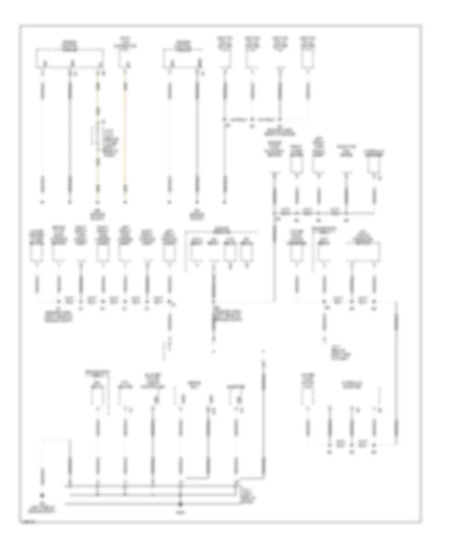
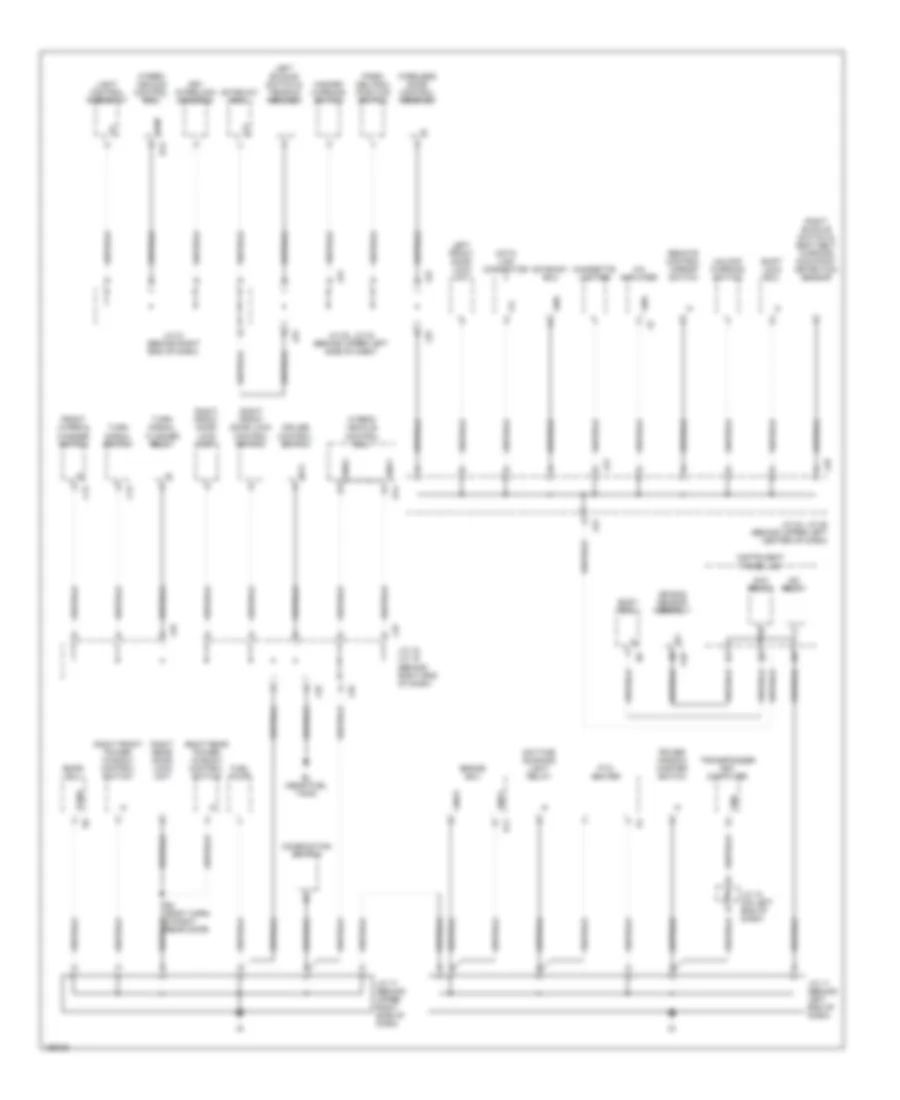
GROUND DISTRIBUTION Ground Distribution Wiring Diagram (1 of 3) for Toyota Prius 2003 List of elements for Ground Distribution Wiring Diagram (1 of 3) for Toyota Prius 2003: 50 A/c triple pressure switch B10 Blower motor linear controller Brake ecu Brake fluid level warning switch Data link connector Drl relay E01 E02 E03 E1 (engine harn, right rear of engine compt) E3 (engine harn, rear of engine) E5 (engine harn, left rear of engine compt) Ea (engine block) Eb (engine block) Ec (left side of engine compt) Efi relay Engine control module Engine hood courtesy switch Engine room j/b Engine room r/b 2 Engine room r/b 3 Fan 2 relay Front wiper motor G202 Gnd Gnd1 Gnd2 Htr relay Hydraulic booster I12 Ig2 relay Igct relay Ignition coil & igniter Inverter J/c 1 (left end of dash) J/c 7 (below right end of dash) J/c 8, j/c 9 (behind lower right j9 side of dash) Left front parking light Left front side marker light Left front turn signal light Me01 Ptc heater Radiator fan motor Right front parking light Right front side marker light Right front turn signal light Water pump motor (a/c) Water pump motor (inverter) Water temper- ature switch Ground Distribution Wiring Diagram (2 of 3) for Toyota Prius 2003 List of elements for Ground Distribution Wiring Diagram (2 of 3) for Toyota Prius 2003: 67 A/c amplifier A18 Acc relay Air bag sensor assembly B11 B3 (body harn, in right rear door) Bl (near fuel tank) Body ecu Brake ecu C12 C13 Cigarette lighter Combination switch Cruise control switch Data link connector Daytime running light relay Ecc Emps ecu Eom Front wiper & washer switch Fuel pump Gateway ecu Gnd Gnd1 Gnd2 Gnd3 Gnd4 H13 H14 Hazard warning switch Hybrid vehicle control ecu Ig2 relay Instrument panel j/b J/c 10 (on left end of dash) J/c 11 (behind left end of dash) J/c 17 (behind upper right side of dash) J/c 18, j/c 19 (behind right end of dash) J/c 21 (behind right end of dash) J/c 22, j/c 23 (behind upper left side of dash) J/c 24, j/c 25 (behind upper left center of dash) J18 J19 J22 J23 J24 J25 Key interlock solenoid Left buckle switch & tension reducer Left front door lock unit Light control rheostat Park/ neutral position switch Pgnd Power window master switch Ptc heater Remote control mirror switch Right buckle switch & seat belt warning occupant detection sensor Right front door lock control switch Right front door lock unit Right front power window control switch Right rear door lock unit Right rear power window control switch Shift lock ecu Transponder key computer Turn signal flasher relay Turn signal switch Unlock warning switch Wireless door control receiver Ground Distribution Wiring Diagram (3 of 3) for Toyota Prius 2003 List of elements for Ground Distribution Wiring Diagram (3 of 3) for Toyota Prius 2003: 32 A18 Air bag sensor assembly B1 (body harn, in left rear door) B17 Battery ecu Battery fan relay Battery input relay Battery motor blower controller Bi (left side of rear pillar) Bj (right side of rear pillar) Bk (center of back panel) C10 Combination meter High mounted stop- light If (left kick panel) Ih (right kick panel) Instrument panel j/b J/c 32, j/c 33 (left rear of vehicle, above left rear wheelwell) J32 J33 Left license plate light Left rear combination light Left rear door lock unit Left rear power window control switch Luggage compartment door unlock switch Multi- display Navigation ecu Personal light Radio & player Right license plate light Right rear combination light System main relay
HEADLIGHTS Headlights Wiring Diagram, with DRL for Toyota Prius 2003 List of elements for Headlights Wiring Diagram, with DRL for Toyota Prius 2003: 62 (above left kick panel) id A10 Body ecu (on right side of instrument panel j/b) C10 Chg- Combination meter Combination switch Daytime running light relay (behind upper left side of dash) Dim Dim relay Dimmer switch Diode (drl) (behind right end of dash) Dome fuse 15a Drl Drl fuse 7.5a Drl relay E2 (in engine compt harness, inside engine room r/b 3) Ecu-b fuse 7.5a Engine room j/b (on left side of engine compt) Engine room r/b 3 (on right rear of engine compt) Flash Gauge fuse 10a H-lp Head Head fuse 30a Head hi (left) 10a Head hi (right) 10a Head indicator Head lo (left) 10a Head lo (right) 10a Head relay High High beam indicator Hot at all times Hot in on or start Hrly Ie (above left kick panel) Ig (above right kick panel) Ih (behind right kick panel) Ind Instrument panel j/b (behind left end of dash) J12 e J13 e J27 f J28 h Junction connector 1 (behind left end of dash, near base of "a" pillar) Junction connector 11 (behind left end of dash, near base of "a" pillar) Junction connector 12 & 13 (behind upper left center of dash) Junction connector 17 (behind upper right side of dash) Junction connector 20 (behind upper left center of dash) Junction connector 27 & 28 (behind upper left center of dash) K10 Left headlight Light control switch Low Off Parking brake switch (at base of parking brake lever) Pkb Rdy Red Right headlight Tail Headlights Wiring Diagram, without DRL for Toyota Prius 2003 List of elements for Headlights Wiring Diagram, without DRL for Toyota Prius 2003: 44 A10 Body ecu (on right side of instrument panel j/b) C10 Combination meter Combination switch D j5 Dimmer switch Dome fuse 15a E j4 E j5 Engine room j/b (on left side of engine compt) F j4 F12 F13 F18 Flash Fusible link block 1 (on left side of engine compt) Fusible link block 2 (behind left rear wheelwell, in luggage compartment) Head Head (left) 10a Head (right) 10a Head indicator Head relay High High beam indicator Hot at all times Hrly Ih (behind right kick panel) Instrument panel j/b (behind left end of dash) J12 f J13 d Junction connector 12 & 13 (behind upper left center of dash) Junction connector 17 (behind upper right side of dash) Junction connector 20 (behind upper left center of dash) Junction connector 4 & 5 (behind upper left end of dash) Left headlight Light control switch Low Main fuse 120a Off Red Right headlight Short pin Tail
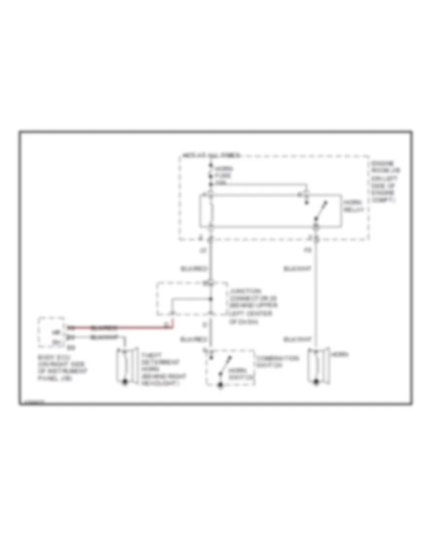
HORN Horn Wiring Diagram for Toyota Prius 2003 List of elements for Horn Wiring Diagram for Toyota Prius 2003: 13 (on left side of engine compt) Body ecu (on right side of instrument panel j/b) Combination switch Engine room j/b Horn Horn fuse 10a Horn relay Horn switch Hot at all times Junction connector 20 (behind upper Left center Of dash) Theft deterrent horn (behind right headlight)
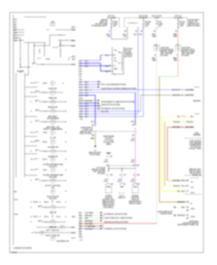
INSTRUMENT CLUSTER Instrument Cluster Wiring Diagram for Toyota Prius 2003 List of elements for Instrument Cluster Wiring Diagram for Toyota Prius 2003: 78 (behind left end of dash) instrument panel j/b (near base of left ``c" pillar) navigation ecu A10 A11 A12 A13 A14 A15 A16 A17 A18 A19 A20 A21 A22 Abs ind Acc fuse 10a Anti-lock brakes system B10 Body ecu (on right side of instrument panel j/b) Brake ind Buzzer C10 C11 Charge ind Combination meter Computer data lines system Cruise ind Dome fuse 15a Door ind E10 Ecu-b fuse 7.5a Electronic power steering system Engine control module (behind right end of dash) Engine controls system Engine room j/b (on left side of engine compt) Exterior lights system Fu+ Fu- Fua Fuel pump & fuel sender (under rear of vehicle, in fuel tank) Fuel sender Gauge fuse 10a H12 Head ind Headlights system High beam ind Hot at all times Hot in acc or on Hot in on or start Hybrid vehicle control ecu (behind right side of dash, forward of glove box) Ih (behind right kick panel) Instrument panel j/b (behind left end of dash) Interior lights system J/c 27 & 28 (behind upper left center of dash) J27 J28 Junction connector 26 (behind upper left center of dash) Junction connector 27 (behind upper left center of dash) Left turn ind Malfunction ind lamp Mpx+ Mpx- Multi display Odo Odo/trip switch (hazard warning switch) Oil ind Output control ind Right turn ind Seat belt ind (driver's) Seat belt ind (front passenger's) Sensor Spd Spdi Srs ind Vfd Water temperature ind (high) Water temperature ind (low)
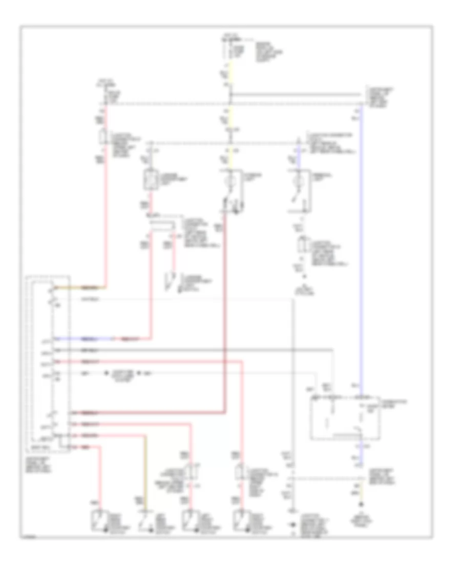
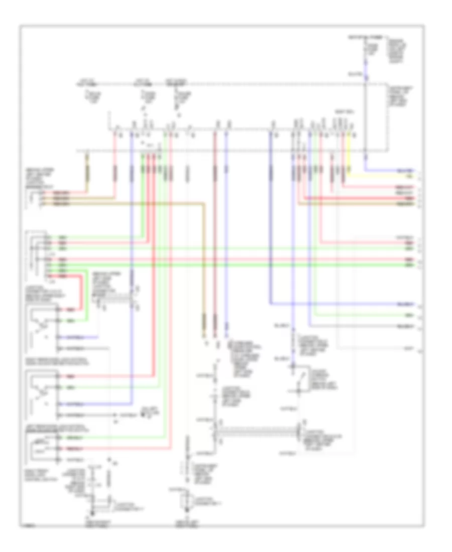
INTERIOR LIGHTS Courtesy Lamps Wiring Diagram for Toyota Prius 2003 List of elements for Courtesy Lamps Wiring Diagram for Toyota Prius 2003: 43 Bi (on left "c" pillar) Body ecu C10 C11 Combination meter Computer data lines system Dcty Dome fuse 15a Door Door ind Ecu-b fuse 7.5a Engine room j/b (on left side of engine compt) Hot at all times Ih (behind right kick panel) Instrument panel j/b (behind left end of dash) Interior light J12 J13 J30 d J30 e J31 d J31 e Junction connector 30 & 31 (left rear of vehicle, above left rear wheelwell) Junction connector 33 (left rear of vehicle, above left rear wheelwell) Junction connector 11 (behind left end of dash, near base of "a" pillar) Junction connector 12 & 13 (behind upper left center of dash) Junction connector 16 (behind upper right side of dash) Junction connector 27 (behind upper left center of dash) Junction connector 30 & 31 (left rear of vehicle, above left rear wheelwell) Lcty Left front door courtesy switch Left rear door courtesy switch Luggage compartment light Luggage compartment light switch Mpx+ Mpx- Off Pcty Personal light Rcty Red Right front door courtesy switch Right rear door courtesy switch Instrument Illumination Wiring Diagram for Toyota Prius 2003 List of elements for Instrument Illumination Wiring Diagram for Toyota Prius 2003: 34 Ashtray illumination Body ecu (on right side of instrument panel j/b) C10 C11 Center cluster switch Combination meter Dc/dc fuse 100a Dome fuse 15a Engine room j/b (on left side of engine compt) F j28 F11 Fusible link block 1 (on left side of engine compt) Hazard warning switch Head Hot at all times If (behind left kick panel) Ih (behind right kick panel) Ill- Instrument panel j/b (behind left end of dash) J27 h J28 f Junction connector 11 (behind left end of dash, near base of "a" pillar) Junction connector 17 (behind upper right side of dash) Junction connector 21 (behind right end of dash) Junction connector 27 & 28 (behind upper left center of dash) Light control rheostat Light control switch (combination switch) Multi- display Off Panel fuse 5a Radio & player Tail Taillight relay Trly
NAVIGATION Navigation Wiring Diagram for Toyota Prius 2003 List of elements for Navigation Wiring Diagram for Toyota Prius 2003: 63 (behind center of dash) +b1 Acc Acc fuse 10a Aui+ Aui- Auo+ Auo- Back-up light relay (behind right side of dash, forward of glove box) C10 C11 Center cluster switch Combination meter Data link connector (dlc) 3 (behind lower left side of dash) Dome fuse 15a Ecu-ig fuse 5a Engine room j/b (on left side of engine compt) Fl+ Fl- Gateway ecu (behind upper center of dash) Gauge fuse 10a Gnd Gnd1 Gtx+ Gtx- Hot at all times Hot in acc or on Hot in on or start If (behind left kick panel) Ih (behind right kick panel) Instrument panel j/b (behind left end of dash) J/c 12 & 13 (behind upper left center of dash) J/c 14 (behind upper right side of dash) J/c 21 (behind right end of dash) J/c 24 & 25 (behind upper left center of dash) J/c 26 (behind upper left center of dash) J/c 27 & 28 (behind upper left center of dash) J/c 27 (behind upper left center of dash) J12 J13 J24 J25 J27 J28 Left "c" pillar) Left front door speaker Multi-display Navigation ecu (near base of Nca Parking brake switch (at base of parking brake lever) Pkb Pnk Radio & player Red Rev Spd Sync Tx+ Tx- Tx1+ Tx1- Tx3+ Tx3-
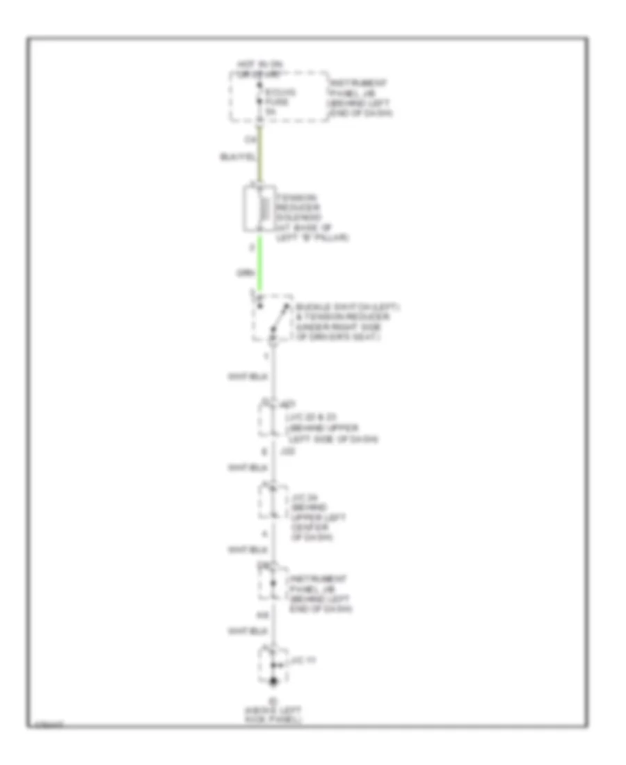
PASSIVE RESTRAINTS Passive Restraints Wiring Diagram for Toyota Prius 2003 List of elements for Passive Restraints Wiring Diagram for Toyota Prius 2003: 12 Buckle switch (left) & tension reducer (under right side of driver's seat) Ecu-ig fuse 5a Hot in on or start Id (above left kick panel) Instrument panel j/b (behind left end of dash) J/c 11 J/c 22 & 23 (behind upper J/c 24 (behind upper left center of dash) J22 J23 Left side of dash) Tension reducer solenoid (at base of left "b" pillar)
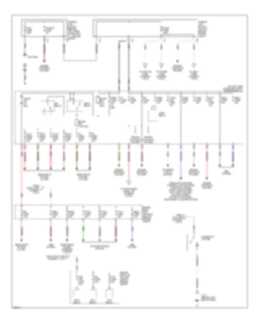
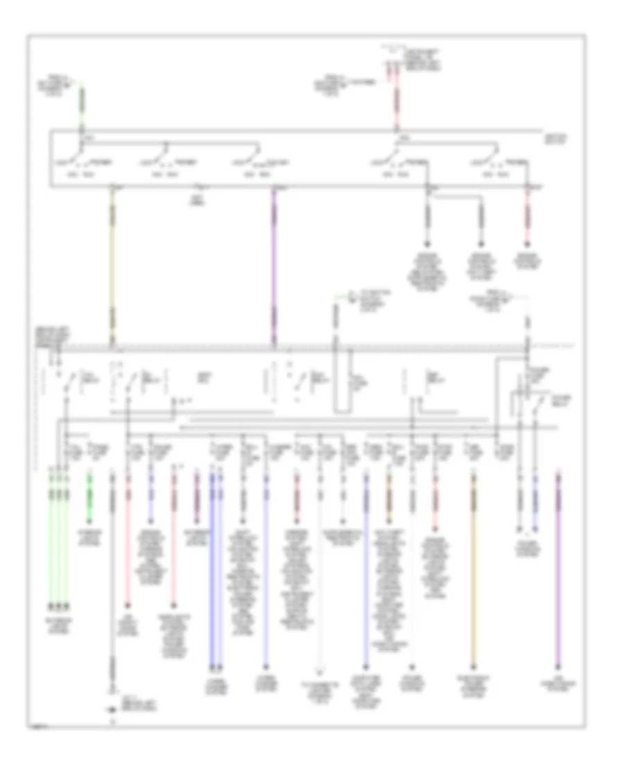
POWER DISTRIBUTION Power Distribution Wiring Diagram (1 of 2) for Toyota Prius 2003 List of elements for Power Distribution Wiring Diagram (1 of 2) for Toyota Prius 2003: 69 (on left side of engine compt) engine room j/b Abs 1 fuse 40a Abs 2 fuse 30a Abs 3 fuse 20a Abs 4 fuse 10a Abs system Air conditioning system Am2 fuse 15a Batt fan fuse 10a Battery Cds fan fuse 30a Cigarette lighter Dc/dc fuse 100a Dc/dc-s fuse 5a Dim relay Dome fuse 15a Drl fuse 7.5a Efi fuse 15a Electronic power steering system Emps fuse 50a Engine controls system Engine room j/b (on left side of engine compt) Engine room r/b 3 (on right rear of engine compt) Exterior lights system F10 F11 F12 F13 F17 Fan 1 relay Fan 3 relay From cig fuse f (diagram 2 of 2) From dc/dc fuse a (diagram 1 of 2) From dc/dc fuse c (diagram 1 of 2) Fusible link block 1 (on left side of engine compt) Fusible link block 2 (behind left rear wheelwell in luggage compt) f18 Head fuse 30a (w/ drl) Head relay Headlights system (w/ drl) Headlights system (w/o drl) Headlights system, interior lights system, warning systems, door locks system, anti-theft system, sound systems, navigation system, instrument cluster system Horn fuse 10a Horn relay Htr 1 fuse 30a Htr 2 fuse 30a Htr 3 fuse 50a Htr fuse 50a Htr relay Hv fuse 20a J/c 11 (behind left end of dash) J11 Lh head fuse 10a Lh hi head fuse 10a Lh lo head fuse 10a Main fuse 120a Nca Rdi fuse 30a Red Rh head fuse 10a Rh hi head fuse 10a Rh lo head fuse 10a Short pin (w/ drl) Short pin (w/o drl) Thro fuse 15a To abs 1 fuse (diagram 1 of 2) To cds fan fuse (diagram 1 of 2) To instrument panel j/b (diagram 2 of 2) To power fuse (diagram 2 of 2) Turn- haz fuse 10a Power Distribution Wiring Diagram (2 of 2) for Toyota Prius 2003 List of elements for Power Distribution Wiring Diagram (2 of 2) for Toyota Prius 2003: 62 (behind left end of dash) instrument panel j/b (not used) Acc Acc fuse 10a Acc relay Air condit- ioning system Air conditioning system Am1 Am1 fuse 5a Am2 Anti-theft system, headlights system, interior lights system, exterior lights system, warning systems, body computer system, door locks system, gateway ecu, air conditioning system Body ecu Cig fuse 15a Computer data lines system, body computer system Def fuse 40a Def relay Door fuse 30a Ecu- b fuse 7.5a Ecu- ig fuse 5a Electronic power steering system Engine controls system Engine controls system, anti-theft system Engine controls system, exterior lights system, shift interlock system, abs system Engine controls system, warning systems, abs system, instrument cluster system Exterior lights system From am1 fuse e (diagram 2 of 2) From am2 fuse d (diagram 1 of 2) From dc/dc fuse b (diagram 1 of 2) Gauge fuse 10a Headlights system, exterior lights system, power windows system Htr fuse 10a Ig1 Ig1 relay Ig2 Ignition switch Instrument panel j/b (behind left end of dash) Interior lights system J/c 11 (behind left end of dash) J11 K10 Lock Obdii fuse 7.5a Panel fuse 5a Power fuse 30a Power relay Power windows system Pwr1 fuse 20a Red Run Shift interlock system, navigation system, gateway ecu, passive restraints system, electronic power steering system, abs system, cooling fans system Srs acc fuse 10a St1 St2 Start Stop fuse 15a Tail fuse 7.5a Tail relay To cigarette lighter (diagram 1 of 2) To ignition switch (diagram 2 of 2) Washer fuse 15a Wiper fuse 30a Wiper/ washer system
POWER DOOR LOCKS Power Door Locks Wiring Diagram (1 of 2) for Toyota Prius 2003 List of elements for Power Door Locks Wiring Diagram (1 of 2) for Toyota Prius 2003: 53 (behind upper left center of dash) junction connector 27 (behind upper left side of dash) junction connector 22 & 23 (on left "c" pillar) bi Act+ Act- Actd Body ecu Control switch Dcty Dome fuse 15a Door fuse 30a Ecu-b fuse 7.5a Engine room j/b (on left side of engine compt) Gauge fuse 10a Hot at all times Hot in run or start Id (above left kick panel) Ig (above right kick panel) Instrument panel j/b (behind left end of dash) J14 J15 J18 J19 J22 J23 J24 J25 Junction connector 11 Junction connector 14 & 15 (behind upper right side of dash) Junction connector 17 Junction connector 18 & 19 (behind a right end of dash) Junction connector 23 (behind upper left side of dash) Junction connector 24 & 25 (behind upper j24 Junction connector 27 (behind upper left center of dash) Ksw Left center of dash) Left rear door lock motor & door unlock detection switch Lock Lsr Lswp Lug Pcty Prg Rcty Rda Red Right front door lock Right rear door lock motor & door unlock detection switch Ul1 Ul2 Unlk Unlock warning switch (behind left side of dash) Wireless door control receiver (w/ wireless door locks) (behind upper left side of dash) Power Door Locks Wiring Diagram (2 of 2) for Toyota Prius 2003 List of elements for Power Door Locks Wiring Diagram (2 of 2) for Toyota Prius 2003: 30 Bj (on right "c" pillar) Cpub Dcty Diode (door courtesy) (behind left end of dash, above instrument panel j/b) Ig (above right kick panel) J12 J13 J19 J24 J25 Junction connector 12 & 13 (behind upper left center of dash) Junction connector 16 (behind upper right side of dash) Junction connector 17 Junction connector 18 & 19 (behind right end of dash) j18 Junction connector 24 & 25 (behind upper left center of dash) Junction connector 33 (left rear of vehicle, above left rear wheelwell) Kul Left front door courtesy switch Left front door lock motor, door key lock & unlock switch & door unlock detection switch Left rear door courtesy switch Lock Lswd Luggage compartment door unlock switch Mpx1 Power window master switch Red Right front door courtesy switch Right front door lock motor, door key lock & unlock switch & door unlock detection switch Right rear door courtesy switch Unlk
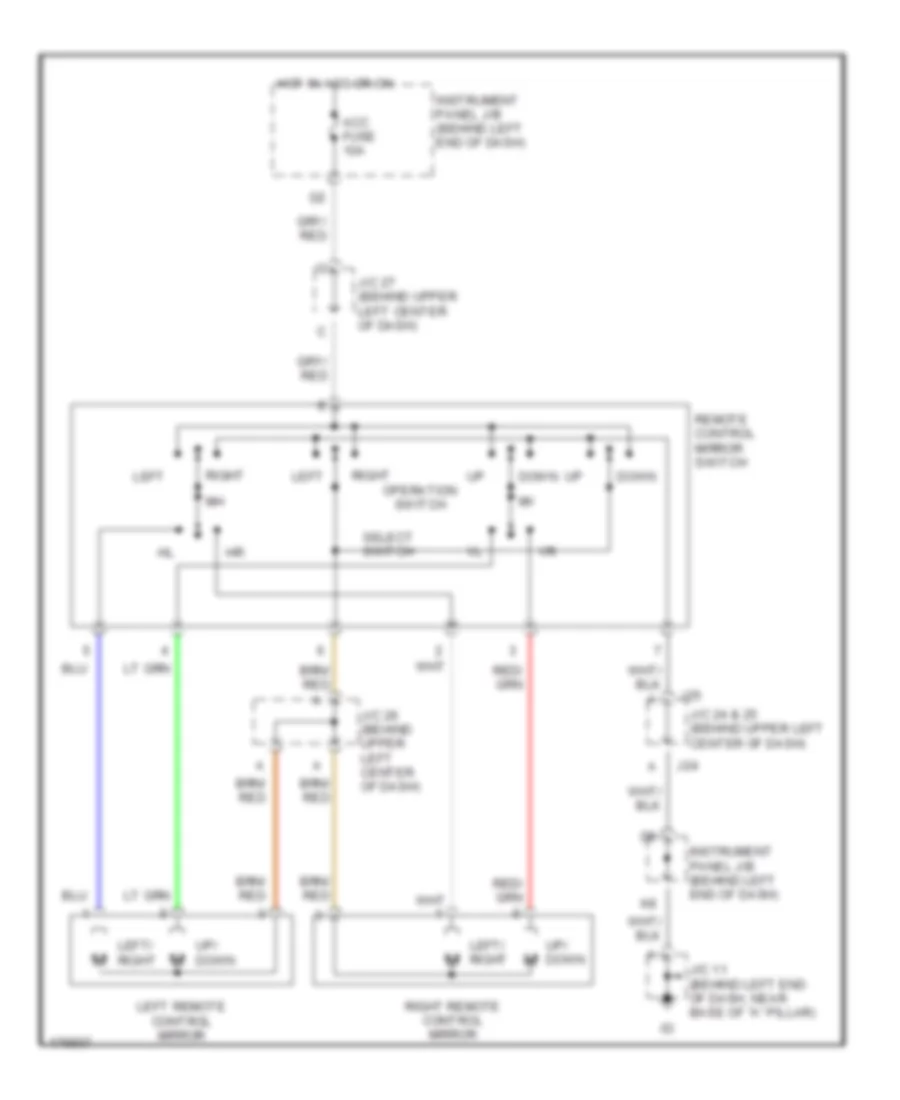
POWER MIRRORS Power Mirrors Wiring Diagram for Toyota Prius 2003 List of elements for Power Mirrors Wiring Diagram for Toyota Prius 2003: 19 Acc fuse 10a Down Hot in acc or on Instrument panel j/b (behind left end of dash) J/c 11 (behind left end of dash, near base of "a" pillar) J/c 24 & 25 (behind upper left center of dash) J/c 26 (behind upper left center of dash) J/c 27 (behind upper left center of dash) J24 J25 Left Left remote control mirror Left/ right Operation switch Remote control mirror switch Right Right remote control mirror Select switch Up/ down
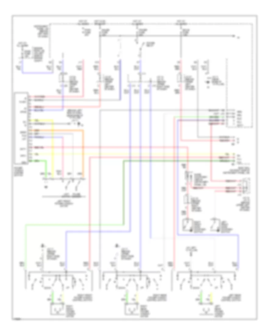
POWER WINDOWS Power Windows Wiring Diagram for Toyota Prius 2003 List of elements for Power Windows Wiring Diagram for Toyota Prius 2003: 59 (at left ``c" pillar) bi (behind left end of dash, near base of ``a" pillar) j/c 11 Body ecu (on right side of instrument panel j/b) Cpub Dcty Ddn Diode (courtesy) (above instrument panel j/b) Dome fuse 15a Down Ecu-b fuse 7.5a Engine room j/b (on left side of engine compt) Fld Flu Gauge fuse 10a Hot at all times Hot in on or start Instrument panel j/b (behind left end of dash) J/c 11 (near base of ``a" pillar) J/c 12, j/c 13 (behind upper left center of dash) J/c 14, j/c 15 (behind upper right side of dash) J/c 16 (behind upper right center of dash) J/c 17 (behind upper right side of dash) J/c 17 (behind uppre right side of dash) J/c 20 (behind upper left center of dash) J/c 24, j/c 25 (behind upper left center of dash) J/c 27 (behind upper left center of dash) J10 J11 J12 J13 J14 a J15 c J24 b J25 c K10 Left front door courtesy switch Left front power window motor Left rear power window control switch Left rear power window motor Limit switch Lmt Mpx1 Pls Power fuse 30a Power relay Power window master switch Pulse sensor Pwr1 fuse 20a Right front door courtesy switch Right front power window control switch Right front power window motor Right rear power window control switch Right rear power window motor Rld Rlu Rrd Rru Sgnd Wlsw
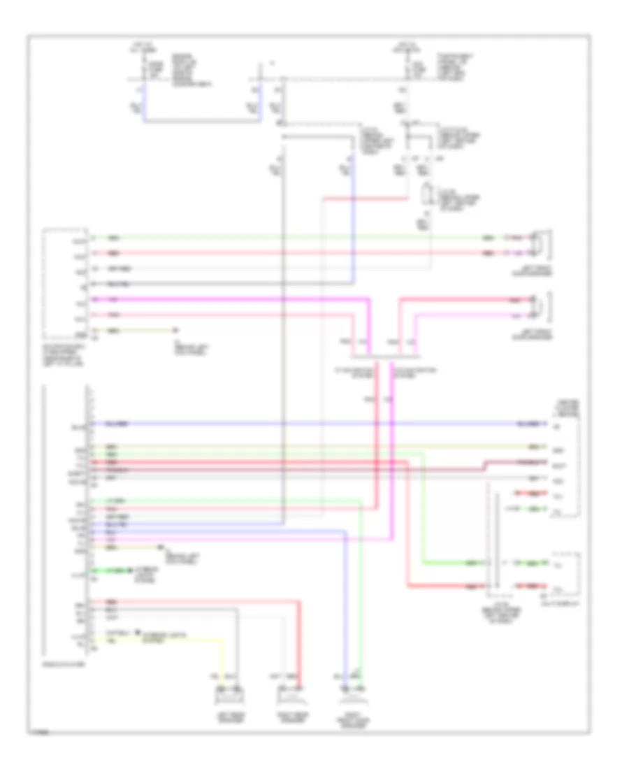
RADIO Radio Wiring Diagram for Toyota Prius 2003 List of elements for Radio Wiring Diagram for Toyota Prius 2003: 47 Acc Acc fuse 10a Acc+b Aui+ Aui- Auo+ Auo- Bu+b C j27 Center cluster switch Dome fuse 15a Ejct Eject Engine room j/b (on left side of engine compartment) Fl+ Fl- Fr+ Fr- Gnd Hot at all times Hot in acc or on If (behind left kick panel) Illum Instrument panel j/b (behind left end of dash) Interior lights system J/c 24 (behind upper left center of dash) J/c 26 (behind upper left center of dash) J/c 27 & 28 (behind upper left center of dash) J27 c J28 c Left front door speaker Left rear speaker Multi-display Navigation ecu (if equipped) (near base of left "c" pillar) Pnk Radio & player Red Right front door speaker Right rear speaker Rl+ Rl- Rr+ Rr- Tx+ Tx- W/ navigation system W/o navigation system
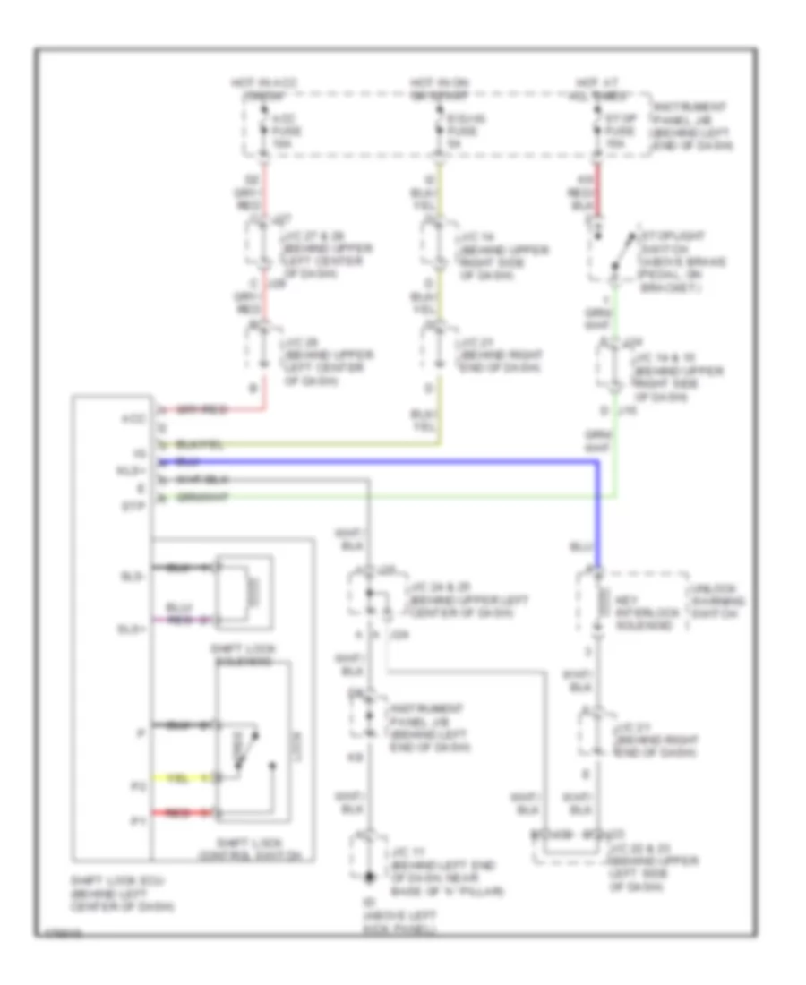
SHIFT INTERLOCK Shift Interlock Wiring Diagram for Toyota Prius 2003 List of elements for Shift Interlock Wiring Diagram for Toyota Prius 2003: 38 A j24 Acc Acc fuse 10a C j28 D j15 D j23 E j22 Ecu-ig fuse 5a Free Hot at all times Hot in acc or on Hot in on or start Id (above left kick panel) Instrument panel j/b (behind left end of dash) J/c 11 (behind left end of dash, near base of "a" pillar) J/c 14 & 15 (behind upper right side of dash) J/c 14 (behind upper right side of dash) J/c 21 (behind right end of dash) J/c 22 & 23 (behind upper left side of dash) J/c 24 & 25 (behind upper left center of dash) J/c 26 (behind upper left center of dash) J/c 27 & 28 (behind upper left center of dash) J14 J25 J27 Key interlock solenoid Kls+ Lock Red Shift lock control switch Shift lock ecu (behind left center of dash) Shift lock solenoid Sls+ Sls- Stop fuse 15a Stoplight switch (above brake pedal, on bracket) Stp Unlock warning switch
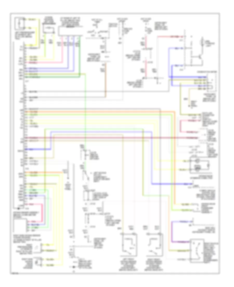
SUPPLEMENTAL RESTRAINTS Supplemental Restraints Wiring Diagram for Toyota Prius 2003 List of elements for Supplemental Restraints Wiring Diagram for Toyota Prius 2003: 76 air bag squib (steering wheel pad) (at base of left "b" pillar, behind trim) (w/side air bags) left side air bag sensor (right kick panel) ih (w/side air bags) left side air bag squib +sl +sr -sl -sr A17 A18 A19 Abfs Acc Acc fuse 10a Air bag sensor assembly (behind lower center of dash) Air bag squib (front passenger air bag assembly) Am2 Body ecu (on right side of instrument panel j/b) C10 C11 Combination meter Data link connector (dlc) 3 (partial) (behind lower left side of dash) Esl Esr Gsw2 H13 Hot at all times Hot in acc or on Hybrid vehicle control ecu (behind right side of dash, forward of glove box) Ig2 Ignition switch Ih (right kick panel) Instrument panel j/b (behind left end of dash) J/c 11 (behind left end of dash, near base of "a" pillar) J/c 22 J/c 22 & j/c 23 (behind upper left side of dash) J/c 23 J/c 24 J/c 24 & j/c 25 (behind upper left center of dash) J/c 25 J/c 26 (behind upper left center of dash) J/c 27 J/c 27 & j/c 28 (behind upper left center of dash) J/c 28 J/c 29 (below center of dash) Lbe+ Left buckle switch (under right side of driver's seat) Left front air bag sensor (on left front of engine compartment, behind headlight) Left pretensioner (at base of left "b" pillar, behind trim) Lock Pl+ Pl- Pnk Pr+ Pr- Rbe+ Right buckle switch & seat belt warning occupant detection sensor (under passenger's seat) Right front air bag sensor (on right front of engine compartment, behind headlight) Right pretensioner (at base of right "b" pillar, behind trim) Right side air bag sensor (w/side air bags) (at base of right "b" pillar, behind trim) Right side air bag squib (w/side air bags) Sfl+ Sfl- Sfr+ Sfr- Sil Spiral cable Srs acc fuse 10a Srs warning light Ssl+ Ssl- Ssr+ Ssr- Start Vupl Vupr
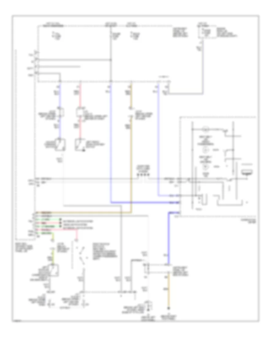
WARNING SYSTEMS Warning Systems Wiring Diagram for Toyota Prius 2003 List of elements for Warning Systems Wiring Diagram for Toyota Prius 2003: 48 Body ecu (on right side of instrument panel j/b) Buzzer C10 C11 Combination meter Computer data lines system Dbkl Dcty Dome fuse 15a Door ind Ecu-b fuse 7.5a Engine room j/b (on left side of engine compt) Exterior lights system F j13 Gauge fuse 10a Headlights system Hot at all times Hot in on or start Hot w/ tail relay energized Id (above left kick panel) Ih (behind right kick panel) Instrument panel j/b (behind left end of dash) J/c 11 (behind left end of dash, near base of "a" pillar) J/c 12 & 13 (behind upper left center of dash) J/c 22 & 23 (behind upper left side of dash) J/c 24 & 25 (behind upper left center of dash) J/c 27 (behind upper left center of dash) J/c 29 (below center of of dash) J12 d J22 e J23 J24 J24 a J25 Ksw Left buckle switch (under right side of driver's seat) Left front door courtesy switch Mpx+ Mpx- Pkbl Red Right buckle switch & seat belt warning occupant detection sensor (under passenger's seat) Seat belt ind (driver's) Seat belt ind (front passenger's) Tail Tail fuse 7.5a Trly Unlock warning switch
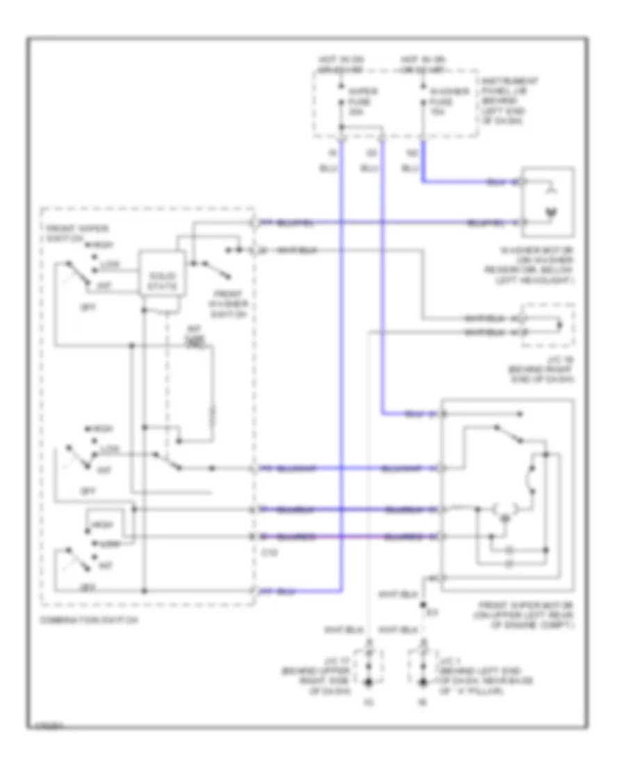
WIPER/WASHER Wiper/Washer Wiring Diagram for Toyota Prius 2003 List of elements for Wiper/Washer Wiring Diagram for Toyota Prius 2003: 19 C12 Combination switch Front washer switch Front wiper motor (on upper left rear of engine compt) Front wiper switch High Hot in on or start Instrument panel j/b (behind left end of dash) Int Int time J/c 1 (behind left end of dash, near base of ``a" pillar) J/c 17 (behind upper right side of dash) J/c 18 (behind right end of dash) Low Off Solid state Washer fuse 15a Washer motor (on washer reservoir, below left headlight) Wiper fuse 30a