ANTI-LOCK BRAKES
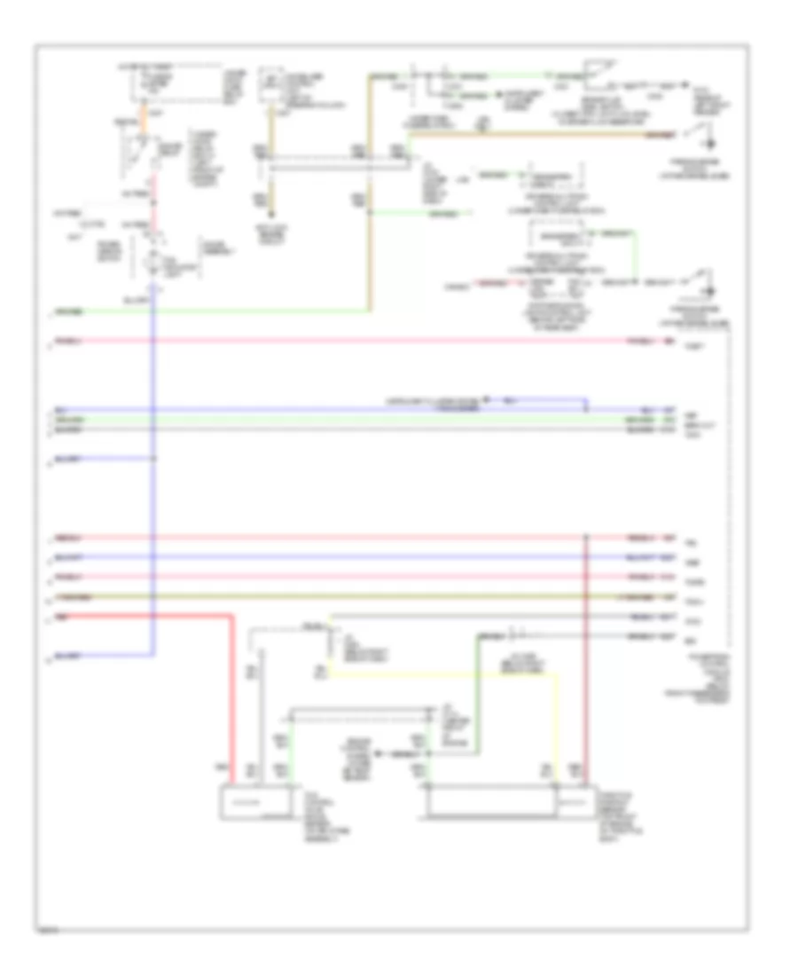
Anti-Lock Brakes Wiring Diagram (1 of 2) for Acura 3.5RL 1996

List of elements for Anti-Lock Brakes Wiring Diagram (1 of 2) for Acura 3.5RL 1996:
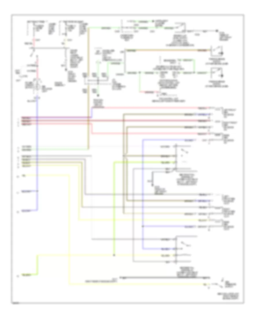
Anti-Lock Brakes Wiring Diagram (2 of 2) for Acura 3.5RL 1996
List of elements for Anti-Lock Brakes Wiring Diagram (2 of 2) for Acura 3.5RL 1996:
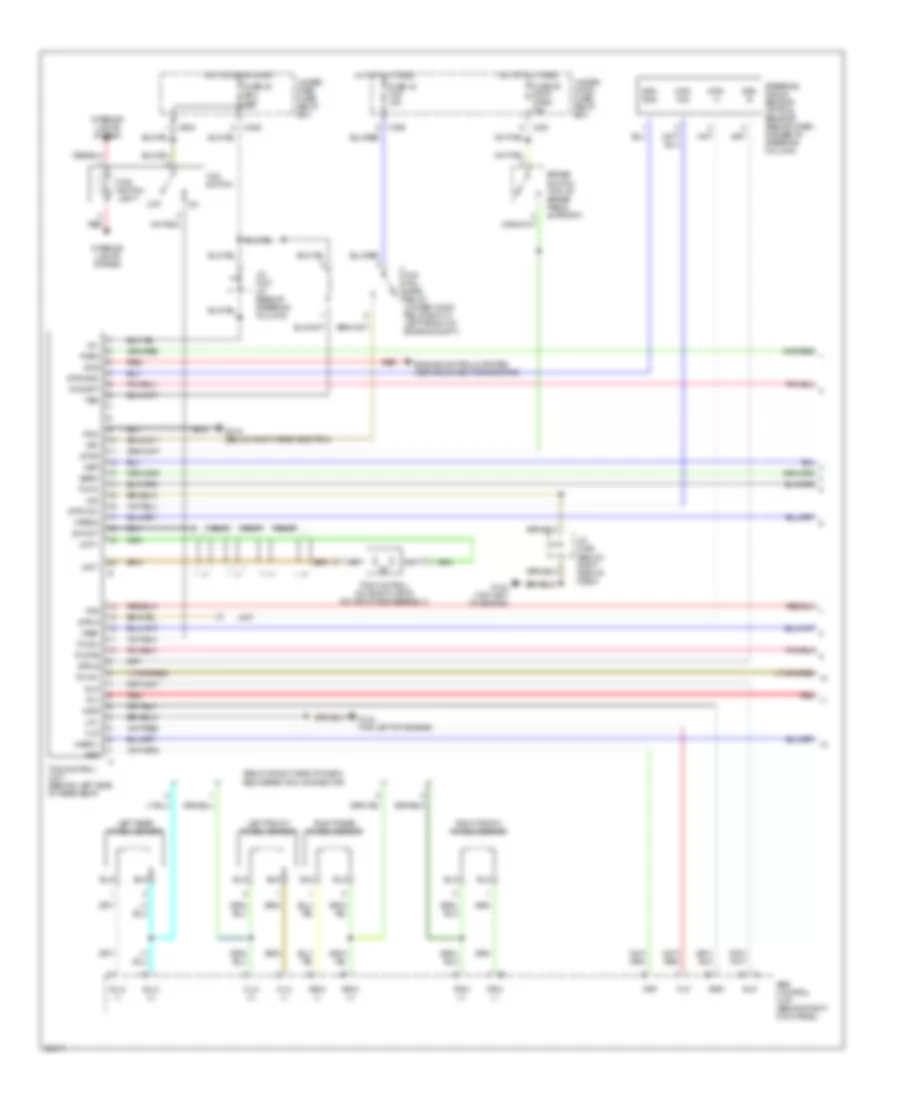
Traction Control Wiring Diagram (1 of 2) for Acura 3.5RL 1996
List of elements for Traction Control Wiring Diagram (1 of 2) for Acura 3.5RL 1996:
Traction Control Wiring Diagram (2 of 2) for Acura 3.5RL 1996
List of elements for Traction Control Wiring Diagram (2 of 2) for Acura 3.5RL 1996: