ANTI-LOCK BRAKES
Advanced Hydraulic Booster Wiring Diagram for Acura ILX 2013

List of elements for Advanced Hydraulic Booster Wiring Diagram for Acura ILX 2013:
- 5v regulator
- A13
- Brake fluid level switch (on brake master cylinder reservoir)
- Brake ind
- Brake pedal position switch (top of brake pedal assembly)
- Brake pedal stroke sensor (hybrid: top of brake pedal assembly)
- Brake system ind (amber)
- C102
- C111
- C16
- Circuit
- Computer data lines system
- D17
- D31
- Driver's junction box 1
- F can transceiver
- F-can h
- F-can l
- Fail safe circuit
- Forced turning on circuit
- Fuse 1-2 40a
- Fuse 10a
- Fuse 15a
- Fuse 7.5a
- G202 (right front of engine compt)
- G401 (hybrid: left end of dash)
- Gauge control module
- Hot at all times
- Hot in on or start
- Indicator drive
- Main circuit
- Micu
- Parking brake switch (base of parking brake lever)
- Pcm (left side of engine compt)
- Power unit (eps) (hybrid: on steering rack)
- Red
- Servo unit (hybrid: left rear of engine compt)
- Under-dash fuse/relay box (under left end of dash)
- Under-hood fuse/relay box (hybrid: left rear of engine compt)
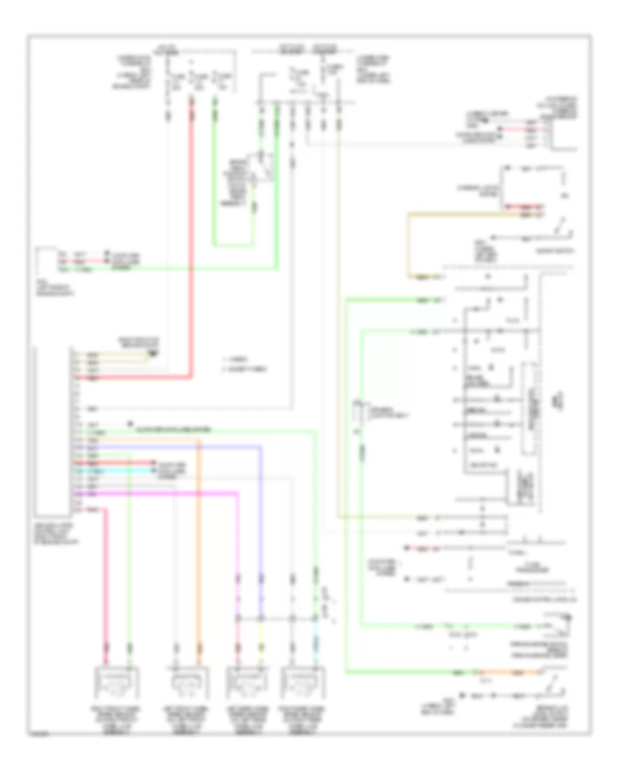
Anti-Lock Brakes Wiring Diagram for Acura ILX 2013
List of elements for Anti-Lock Brakes Wiring Diagram for Acura ILX 2013:
- (hybrid: center of dash) g502
- (in steering column cover) steering angle sensor
- (right front of engine compt) g202
- A13
- Abs ind
- Brake fluid level switch (on brake master cylinder reservoir)
- Brake ind (red)
- Brake pedal position switch (top of
- C102
- C103
- C111
- C120
- C123
- C16
- Circuit indicator drive
- Circuit main
- Computer data lines system
- D31
- Driver's junction box 1
- Except hybrid
- F-can h
- F-can l
- F-can transceiver
- Fuse 1-3 30a
- Fuse 1-4 30a
- Fuse 15a
- Fuse 5 7.5a
- Fuse 7.5a
- G401 (hybrid: left end of dash)
- G501 (hybrid: left end of dash)
- Gauge control module
- Hot at all times
- Hot in on or start
- Hybrid
- Interior lights system
- Left front wheel speed sensor (on left front wheel hub assembly)
- Left rear wheel speed sensor (on left rear wheel hub assembly)
- Micu
- On circuit turning compulsory
- P15
- Parking brake switch (base of parking brake lever)
- Pcm (left side of engine compt)
- Pnk
- Red
- Right front wheel speed sensor (on right front wheel hub assembly)
- Right rear wheel speed sensor (on right rear wheel hub assembly)
- Under-dash fuse/relay box (under left end of dash)
- Under-hood fuse/relay box (hybrid: left rear of engine compt)
- Vsa ind
- Vsa modulator control unit (right front of engine compt)
- Vsa off ind
- Vsa off switch