ANTI-LOCK BRAKES
Anti-lock Brakes Wiring Diagram (1 of 2) for Acura Integra GS-R 1997

List of elements for Anti-lock Brakes Wiring Diagram (1 of 2) for Acura Integra GS-R 1997:
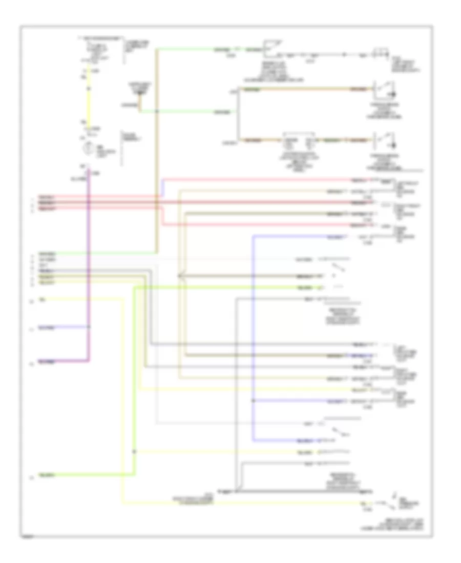
Anti-lock Brakes Wiring Diagram (2 of 2) for Acura Integra GS-R 1997
List of elements for Anti-lock Brakes Wiring Diagram (2 of 2) for Acura Integra GS-R 1997: