ANTI-LOCK BRAKES
Anti-lock Brakes Wiring Diagram (1 of 2) for Acura Integra LS 2001

List of elements for Anti-lock Brakes Wiring Diagram (1 of 2) for Acura Integra LS 2001:
- (on right side of front console)
- 4
- Abs b1 fuse 62 20a
- Abs control unit (hatchback: behind right quarter panel trim, sedan: right side of luggage compartment, behind trim panel)
- Abs fail- safe relay (right front of engine compt)
- Abs motor fuse 61 40a
- Abs pump motor relay
- Abs unit fuse 65 10a
- Brake switch (on brake pedal support)
- C212
- C213
- C216
- C438
- C703
- C704
- Data link connector
- Dlc
- Fl-in
- Fl-out
- Flw (+)
- Flw (-)
- Fr-in
- Fr-out
- Frw (+)
- Frw (-)
- Fsr
- G101 (right front corner of eng compt)
- G401 (right quarter panel)
- Gnd1
- Gnd2
- Gnd3
- Gnd4
- Horn, stop fuse 52 20a
- Hot at all times
- Hot in on
- Ig2
- J/c c418 (above left kick panel)
- Left front wheel sensor
- Left rear wheel sensor
- Mck
- Park
- Pmr
- Rear defroster relay fuse 16 7.5a
- Right front wheel sensor
- Right rear wheel sensor
- Rl-in
- Rl-out
- Rlw (+)
- Rlw (-)
- Rr-in
- Rr-out
- Rrw (+)
- Rrw (-)
- Scs
- Service check connector (above right kick panel)
- Stop
- Under- hood fuse/ relay box
- Underdash fuse/relay box
- Underhood abs fuse/relay box
- Warn 1
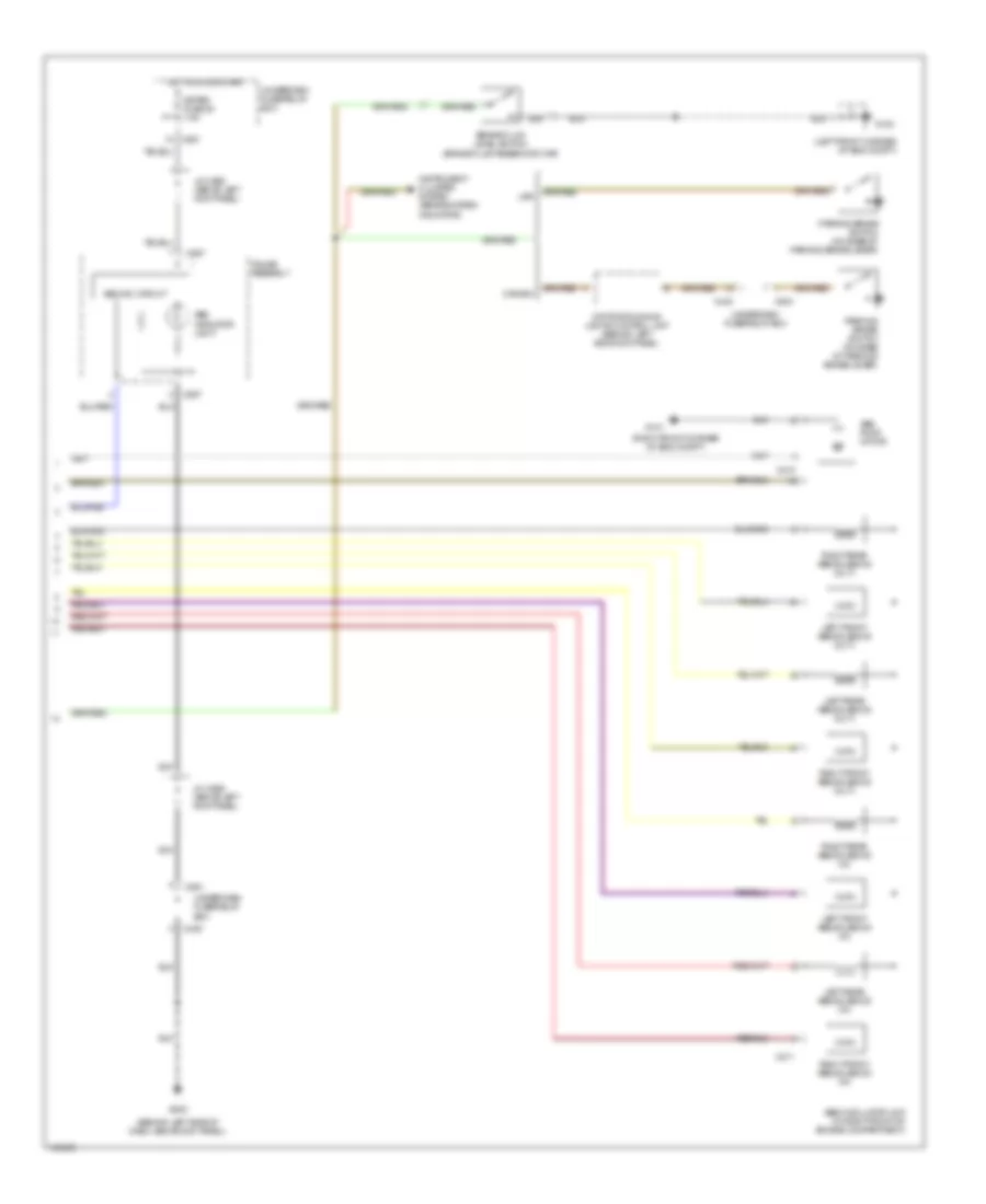
Anti-lock Brakes Wiring Diagram (2 of 2) for Acura Integra LS 2001
List of elements for Anti-lock Brakes Wiring Diagram (2 of 2) for Acura Integra LS 2001:
- (behind left side of dash, above kick panel)
- (left front corner of eng compt)
- (right front corner of eng compt)
- Abs ind. circuit
- Abs indicator light
- Abs modulator unit (in right front of engine compartment)
- Abs pump motor
- Brake fluid level switch (brake fluid reservoir cap)
- C210
- C211
- C439
- C440
- C504
- C551
- C557
- Canada
- Daytime running lights control unit (behind left side kick panel)
- G100
- G101
- G202
- Gauge assembly
- Hot in on or start
- Instrument cluster system (brake system indicator)
- J/c c556 (above left kick panel)
- Left front abs solenoid (in)
- Left front abs solenoid (out)
- Left rear abs solenoid (in)
- Left rear abs solenoid (out)
- Meter fuse 25 7.5a
- Parking brake switch (on base of parking brake lever)
- Right front abs solenoid (in)
- Right front abs solenoid (out)
- Right rear abs solenoid (in)
- Right rear abs solenoid (out)
- Underdash fuse/relay box
- Usa