ANTI-LOCK BRAKES
Anti-lock Brakes Wiring Diagram (1 of 2) for Acura RDX 2013

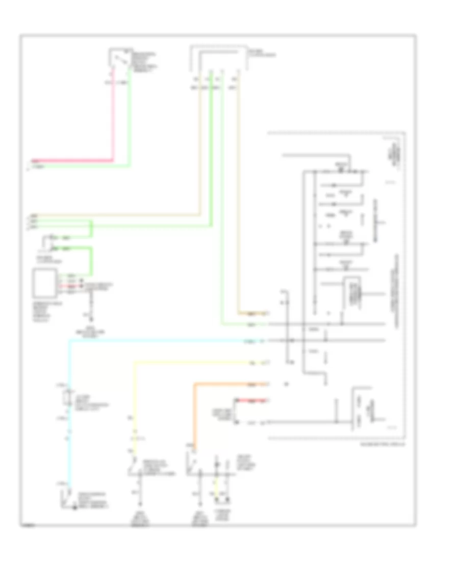
List of elements for Anti-lock Brakes Wiring Diagram (1 of 2) for Acura RDX 2013:
- (right kick panel) g404
- A19
- A20
- Brake booster pressure sensor a (on brake booster)
- Brake booster pressure sensor b (on brake booster)
- C121
- C125
- C16
- Computer data lines system
- D11
- D14
- D17
- Fuse 1-3 40a
- Fuse 1-4 20a
- Fuse 10a
- Fuse 7.5a
- G404 (right kick panel)
- Hot at all times
- Hot in on or start
- J/c c019 (left kick panel)
- Left front wheel speed sensor (at left front wheel)
- Left rear wheel speed sensor (at left rear wheel)
- Micu
- P15
- Pnk
- Q16
- Red
- Right front wheel speed sensor (at right front wheel)
- Right rear wheel speed sensor (at right rear wheel)
- Under-dash fuse/relay box (behind left side of dash)
- Under-hood fuse/relay box (left rear of engine compt)
- Vsa control unit (right side of engine compt)
Anti-lock Brakes Wiring Diagram (2 of 2) for Acura RDX 2013
List of elements for Anti-lock Brakes Wiring Diagram (2 of 2) for Acura RDX 2013:
- Abs ind
- Brake fluid level switch (in brake master cylinder)
- Brake ind
- Brake pedal position switch (brake pedal assembly)
- Brake system ind
- C114
- Center junction box 2
- Circuit turning-on compulsory
- Computer data lines system
- Driver's junction box
- Fcan-h
- Fcan-l
- G302 (below air filter assembly)
- G501 (behind left side of dash)
- G503 (behind center of dash)
- Gauge control module
- Indicator drive circuit
- Interior lights system
- J/c c008 (below multi-information display unit)
- Multi information display
- Parking brake switch (parking brake pedal assembly)
- Pnk
- Red
- Steering angle sensor (top of steering column)
- Transceiver f can
- Vsa ind
- Vsa off ind
- Vsa off switch (left side of dash)