ANTI-LOCK BRAKES
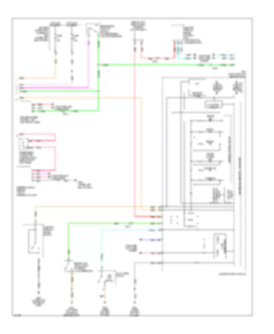
Anti-lock Brakes Wiring Diagram (1 of 2) for Acura RLX 2014

List of elements for Anti-lock Brakes Wiring Diagram (1 of 2) for Acura RLX 2014:
- (behind left side of dash) driver's junction box 1
- (right rear corner of engine compt) g202
- Brake booster pressure sensor (left rear of engine compt)
- Brake light relay
- C206
- C213
- C237
- C238
- C402
- C404
- Computer data lines system
- E24
- E25
- E26
- E53
- E54
- E86
- Exterior lights system
- Fuse 2-3 30a
- Fuse 2-7 40a
- Fuse 7.5a
- G202 (right rear corner of engine compt)
- Hot at all times
- Left front wheel speed sensor (on left front wheel hub assembly)
- Left rear wheel speed sensor (on left rear wheel hub assembly)
- Main under-hood fuse box (left side of engine compt)
- Nca
- Pnk
- Red
- Right front wheel speed sensor (on right front wheel hub assembly)
- Right rear wheel speed sensor (on right rear wheel hub assembly)
- Under-hood fuse/relay box (left rear of engine compt)
- Vsa modulator control unit (right side of engine compt)
Anti-lock Brakes Wiring Diagram (2 of 2) for Acura RLX 2014
List of elements for Anti-lock Brakes Wiring Diagram (2 of 2) for Acura RLX 2014:
- (behind left side of dash) driver's junction box 2
- (tft) display information multi
- 3.3v
- 32bit microcomputer + flash rom
- 5v control circuit
- 8mb/32mb flash
- A11
- A12
- A25
- A27
- A28
- A32
- Abs ind
- Brake fluid level switch (on brake fluid reservoir)
- Brake ind
- Brake pedal position switch (on brake pedal mounting bracket)
- Brake system ind
- C203
- C214
- C406
- Circuit fail-safe
- Circuit turning-on compulsory
- Cmbs ind
- Computer data lines system
- Display (dot lcd)
- Driver's under-dash fuse/relay box (under left end of dash)
- E26
- Electric parking brake control unit (left front of luggage compt)
- Electric parking brake switch
- F-can h
- F-can l
- Fuse 10a
- Fuse 7.5a
- G401 (left rear corner of engine compt)
- G501 (upper left end of dash)
- G502 (upper left end of dash)
- G503 (lower left center of dash)
- Gauge control module
- Hot in on or start
- Keyless access control unit (left end of dash)
- Multi information
- Multi visor switch
- Passenger's under-dash fuse/relay box (behind right kick panel)
- Pcm (right front of engine compt)
- Pnk
- Red
- Steering angle sensor (top of steering column)
- Transceiver f can
- Vsa ind
- Vsa off ind
- Vsa off switch
- Warning driver circuit