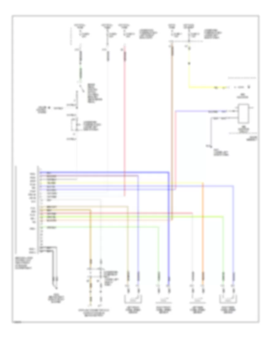
ANTI-LOCK BRAKES
Anti-lock Brakes Wiring Diagram for Acura RSX Type S 2004
List of elements for Anti-lock Brakes Wiring Diagram for Acura RSX Type S 2004:
- A14
- Abs indicator
- Abs indicator circuit
- Abs modulator control unit (right front of engine compartment)
- B18
- Brake pedal position switch (on pedal bracket, above brake pedal)
- C10
- Cruise control system
- Data link connector (dlc) (in front console, behind ashtray)
- Dlc
- Fls -
- Frs +
- Frs +b
- Frs -
- Frs+
- Fuse 10 30a
- Fuse 10 7.5a
- Fuse 11 7.5a
- Fuse 8 20a
- G202 (behind right side of front bumper)
- G401 (under left side of dash)
- Gauge assembly
- Gnd 1
- Gnd 2
- Hot at all times
- Hot in on or start
- Hot in times
- Ig2
- Left front wheel speed sensor
- Left rear wheel speed sensor
- Mr +b
- Right front wheel speed sensor
- Right rear wheel speed sensor
- Rls -
- Rls+
- Rr +
- Rr-
- Scs
- Stop
- Underdash fuse/relay box (under left side of dash)
- Underhood fuse/relay box (left side of eng compt)
- Walp
 English