ANTI-LOCK BRAKES
Anti-lock Brakes Wiring Diagram (1 of 2) for Acura TL 2007

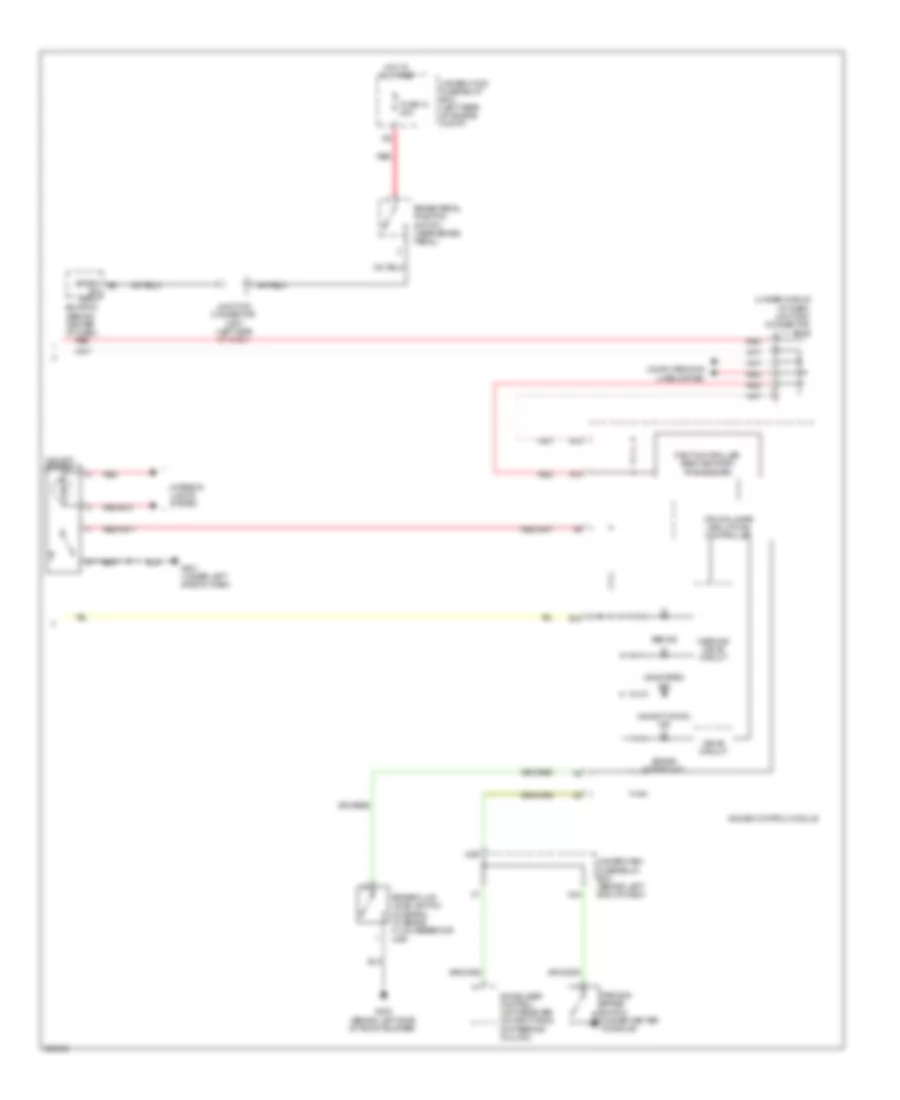
List of elements for Anti-lock Brakes Wiring Diagram (1 of 2) for Acura TL 2007:
- (under center console) yaw rate-lateral acceleration sensor
- C10
- C12
- Can-h
- Can-l
- Computer data lines system
- E12
- Fl +b
- Fl -gnd
- Fr +b
- Fr -gnd
- Fsr +b
- Fuse 17 30a
- Fuse 18 15a
- Fuse 18 40a
- Fuse 21 7.5a
- G203 (right side of engine compt)
- Glat
- Ground
- Hot at all times
- Hot in on or start
- Ignition in
- Junction connector c506 (left side of dash)
- K-line
- Left front wheel speed sensor (left side of engine compt)
- Left rear wheel speed sensor (under left rear of vehicle)
- Mr +b
- Pnk
- Red
- Right front wheel speed sensor (on right side of engine compt)
- Right rear wheel speed sensor (under right rear of vehicle)
- Rl +b
- Rl -gnd
- Rr +b
- Rr -gnd
- Sgnd
- Steering angle sensor (on side of steering column)
- Str-a
- Str-b
- Str-d
- Svcc
- Under-dash fuse/relay box (behind left end of dash)
- Under-hood fuse/relay box (left rear of engine compt)
- Vsa modulator unit (on right side of engine compt)
- X34
- Yaw
Anti-lock Brakes Wiring Diagram (2 of 2) for Acura TL 2007
List of elements for Anti-lock Brakes Wiring Diagram (2 of 2) for Acura TL 2007:
- (bksw) e8
- (under middle of dash) junction connector c512
- A13
- A14
- Abs ind
- B18
- Brake fluid level switch (integral to brake fluid reservoir cap)
- Brake pedal position switch (near brake pedal)
- Brake system ind
- Computer data lines system
- Cpu/fail safe circuit/can controller
- Drive circuit
- Ecm/pcm (behind center of dash)
- Fast controller area network transceiver
- Fuse 13 20a
- G302 (behind left side of front bumper)
- G501 (under left side of dash)
- Gauge control module
- Hot at all times
- Immobilizer control unit-receiver (on right side of steering column)
- Interior lights system
- Junction connector c507 (left side of dash)
- N30
- N34
- Parking brake switch (under center console)
- Red
- Sw input
- Under-dash fuse/relay box (behind left end of dash)
- Under-hood fuse/relay box (left rear of engine compt)
- Vsa activation ind
- Vsa off switch
- Vsa system ind
- Warning drive circuit