ANTI-LOCK BRAKES
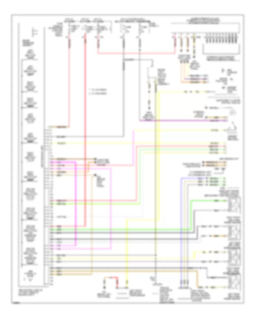
Anti-lock Brakes Wiring Diagram, with Hill-Hold Assist for Audi A3 2.0T 2010

List of elements for Anti-lock Brakes Wiring Diagram, with Hill-Hold Assist for Audi A3 2.0T 2010:
Anti-lock Brakes Wiring Diagram, without Hill-Hold Assist for Audi A3 2.0T 2010
List of elements for Anti-lock Brakes Wiring Diagram, without Hill-Hold Assist for Audi A3 2.0T 2010: