ANTI-LOCK BRAKES
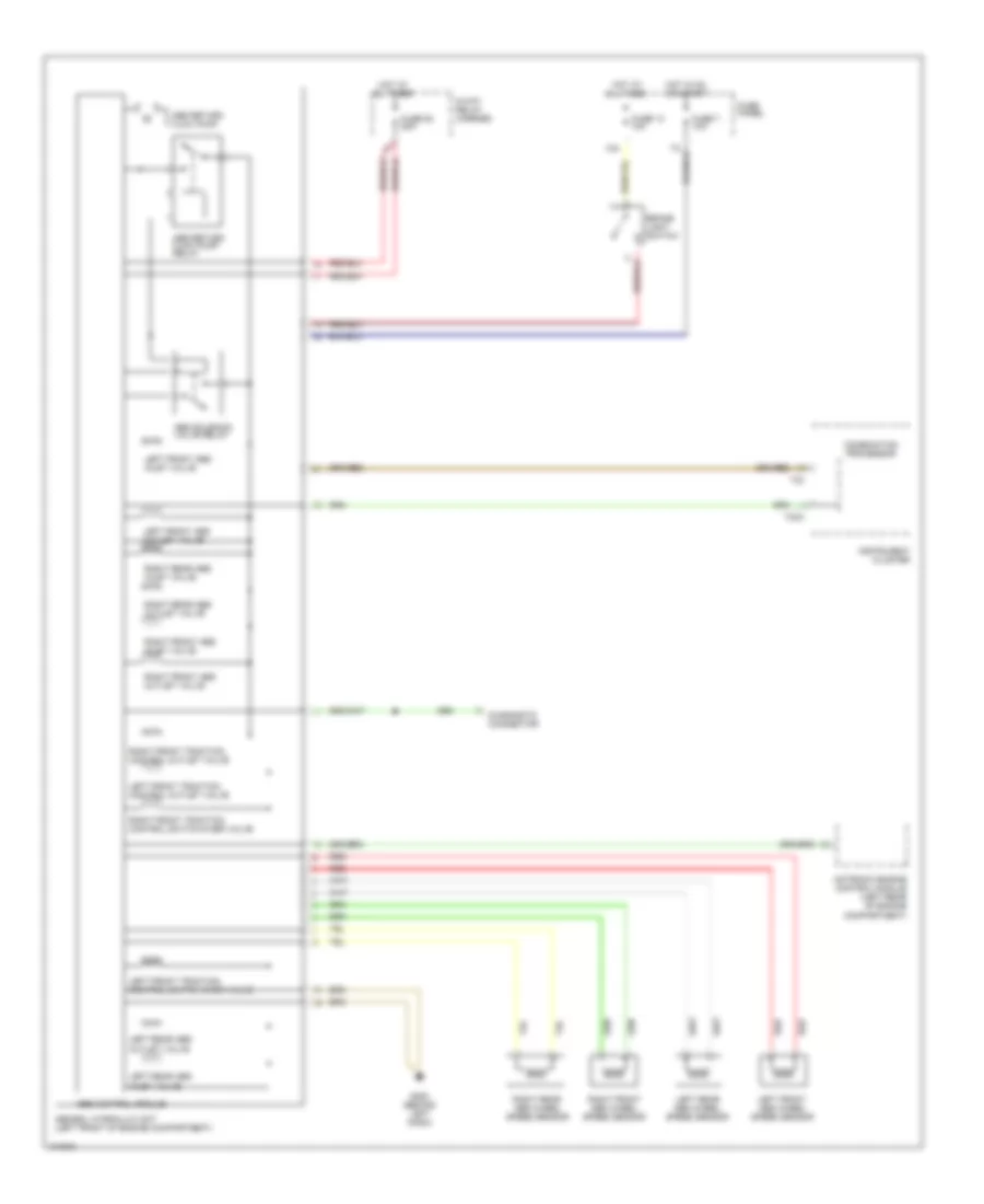
Anti-lock Brakes Wiring Diagram, FWD for Audi A4 1998

List of elements for Anti-lock Brakes Wiring Diagram, FWD for Audi A4 1998:
- 13a
- 8-way relay carrier
- Abs control module
- Abs return flow pump
- Abs return flow pump relay
- Abs solenoid valve relay
- Abs/edl hydraulic unit (left front of engine compartment)
- All times
- Anti-slip control switch
- Brake light switch
- Combination processor
- Diagnostic connector
- Fuse 13 10a
- Fuse 53 60a
- Fuse 7 10a
- Fuse panel
- G202 (behind left dash)
- Hot at
- Hot in on or start
- Instrument cluster
- Left front abs inlet valve
- Left front abs outlet valve
- Left front abs wheel speed sensor
- Left front traction control outlet valve
- Left front traction control switch-over valve
- Left rear abs inlet valve
- Left rear abs outlet valve
- Left rear abs wheel speed sensor
- Motronic engine control module (left rear of engine compartment)
- Red
- Right front abs inlet valve
- Right front abs outlet valve
- Right front abs wheel speed sensor
- Right front traction control outlet valve
- Right front traction control switch-over valve
- Right rear abs inlet valve
- Right rear abs outlet valve
- Right rear abs wheel speed sensor
- T32
- T32a
- Traction control ind
- Transmission control module (under carpet forward of passenger's seat)
- W/ anti-slip control
- W/o anti-slip control
Anti-lock Brakes Wiring Diagram, Quattro for Audi A4 1998
List of elements for Anti-lock Brakes Wiring Diagram, Quattro for Audi A4 1998:
- 13a
- 8-way relay carrier
- Abs control module
- Abs return flow pump
- Abs return flow pump relay
- Abs solenoid valve relay
- Abs/edl hydraulic unit (left front of engine compartment)
- All times
- Brake light switch
- Combination processor
- Diagnostic connector
- Fuse 13 10a
- Fuse 53 50a
- Fuse 7 10a
- Fuse panel
- G202 (behind left dash)
- Hot at
- Hot in on or start
- Instrument cluster
- Left front abs inlet valve
- Left front abs outlet valve
- Left front abs wheel speed sensor
- Left front traction control outlet valve
- Left front traction control switch-over valve
- Left rear abs inlet valve
- Left rear abs outlet valve
- Left rear abs wheel speed sensor
- Motronic engine control module (left rear of engine compartment)
- Red
- Right front abs inlet valve
- Right front abs outlet valve
- Right front abs wheel speed sensor
- Right front traction control outlet valve
- Right front traction control switch-over valve
- Right rear abs inlet valve
- Right rear abs outlet valve
- Right rear abs wheel speed sensor
- T32
- T32a