ANTI-LOCK BRAKES
Anti-lock Brakes Wiring Diagram for Audi A4 Avant Quattro 2004
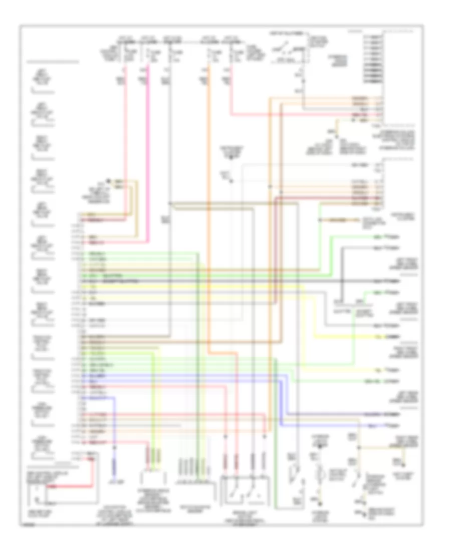
List of elements for Anti-lock Brakes Wiring Diagram for Audi A4 Avant Quattro 2004:
- (behind right side of dash) g33
- (except quattro)
- (on left of firewall, near coolant reservoir)
- (quattro)
- 13a
- 14a
- 42a
- Abs control module (on left side of engine compt)
- Abs control module fuse 1
- Abs return flow pump
- Acc
- Anti-slip control switch
- Anti-theft system
- Brake light switch (above brake pedal, on bracket)
- Data link connector (dlc)
- Except quattro
- Fuse 10a
- Fuse 25a
- Fuse 50a
- Fuse holder (left end of dash)
- G12
- G33 (w/o conv) (behind right side of dash)
- G49 (w/ conv) (behind left side of dash)
- High pressure switch valve 1
- High pressure switch valve 2
- Hot at all times
- Hot in on or start
- Ignition/ starter switch
- Instrument cluster
- Instrument cluster system
- Interior lights system
- Left front abs inlet valve
- Left front abs outlet valve
- Left front abs wheel speed sensor
- Left rear abs inlet valve
- Left rear abs outlet valve
- Left rear abs wheel speed sensor
- Navigation control module (w/o convertible) (at left rear of luggage compt)
- Nca
- Off
- Parking brake warning light switch
- Quattro
- Red
- Right front abs inlet valve
- Right front abs outlet valve
- Right front abs wheel speed sensor
- Right rear abs inlet valve
- Right rear abs outlet valve
- Right rear abs wheel speed sensor
- Rotation rate sender
- Run
- Start
- Steering angle sensor
- Steering angle sensor 1 (convertible) brake booster sender 1 (w/o convertible)
- Steering column electronic systems control module (in top of steering column)
- T16a
- T26
- T32
- T32a
- Traction control pilot valve 1
- Traction control pilot valve 2
 English